class rules construction and … 12’ dinghy class class rules construction and measurement...
TRANSCRIPT
1
12’ Dinghy Class
CLASS RULES CONSTRUCTION AND MEASUREMENT
Official English Translation In case of conflict between the Italian and the English version, the Italian version shall prevail. FOREWORD The purpose of these rules and annexed tables is to guarantee that any new construction of a 12’ Dinghy is compliant with her original design (Cockshott, 1913). Based on the use of the most recent materials and methods, these rules aim to improve upon the sailing qualities and sea-worthiness which resulted in the 12’ Dinghy being selected as the single-handed Olympic Class in the 1920s.
2
TABLE OF CONTENTS
1. GENERAL ................................................................................................................................... 4
1.1 The 12’ Dinghy .................................................................................................................... 4
1.2 One design ........................................................................................................................... 4
1.3 Language and definitions ..................................................................................................... 4 1.4 Measurement and tolerances ................................................................................................ 4 1.5 Rule amendment and interpretation ..................................................................................... 5 1.6 Measurement certificate and procedure ............................................................................... 5 1.7 Helmsman’s and owner’s responsibilities ........................................................................... 5 1.8 Construction license ............................................................................................................. 6 1.9 Construction plaque, sail number and measurer’s stamp .................................................... 6
1.10 Boat design by registered builders ....................................................................................... 7 2. CONSTRUCTION RULES ......................................................................................................... 8
2.0 General ................................................................................................................................. 8
2.1 Hull ...................................................................................................................................... 8
2.1.1 Key measures ............................................................................................................... 8 2.1.2 Waterlines ........................................................................................................................ 8
2.1.3 Weight distribution ........................................................................................................ 10 2.1.4 Benches, rowing thwarts, breast-hook and mast bench, rowlocks and keelson ............ 11
2.1.5 Bailers, buoyancy tanks, double bottom, floorboards. .................................................. 11
2.2 Rudder and Centerboard .................................................................................................... 15 2.2.1 Rudder ............................................................................................................................ 15
2.2.2 Centerboard .................................................................................................................... 16 2.3 Spars .................................................................................................................................. 18
2.3.1 Mast ............................................................................................................................... 19
2.3.2 Boom.............................................................................................................................. 20
2.3.3 Gaff ................................................................................................................................ 21
2.4 Mainsail ............................................................................................................................. 22
2.4.1 Mainsail ......................................................................................................................... 22
2.5 Rigging .............................................................................................................................. 24
2.5.1 Shrouds .......................................................................................................................... 24
2.5.2 Chain plates ................................................................................................................... 24 2.5.3 Traveler .......................................................................................................................... 24
2.5.4 Halyard .......................................................................................................................... 24
2.5.5 Running rigging ............................................................................................................. 24 2.6 Construction rules for Classical Dinghies ......................................................................... 26
2.6.1 Hull ................................................................................................................................ 26
2.6.2 Key measures ................................................................................................................. 26 2.6.3 Waterlines ...................................................................................................................... 26
2.6.4 Hull details ..................................................................................................................... 26
2.7 Construction rules for Modern Dinghies ........................................................................... 32 2.7.0 Foreword ........................................................................................................................ 32
2.7.1 GRP/wooden boats ........................................................................................................ 37 2.7.2 Wholly GRP boats ......................................................................................................... 39 2.7.3 – Glued boats of marine plywood or solid wood .............................................................. 41
3. CONSTRUCTION PLANS ....................................................................................................... 47 4. MEASUREMENT RULES ....................................................................................................... 48
4.0 General ............................................................................................................................... 48
3
4.1 Hull Measuring Procedures ............................................................................................... 48 4.1.1 Hull weight .................................................................................................................... 48 4.1.2 Swing test....................................................................................................................... 49
4.1.4 Measurement of GRP moulds and prototypes ............................................................... 50
4.1.5 Measurement of GRP hulls with conformity statement ................................................ 51
4.1.6 Measurement of the position of the centerboard pivot and sweep back angle .............. 51
4.2 Measurement of centerboard, rudder and spars ................................................................ 51 4.3 Sail sizes ............................................................................................................................ 52
5. PROCEDURES FOR CONSTRUCTION LICENCE, CONFORMITY CERTIFICATION AND MEASUREMENT OF HULL, RUDDER, CENTREBOARD, SPARS AND SAIL .............. 53
5.1 Construction License ......................................................................................................... 54 5.1.1 Notification of hull construction start-up ...................................................................... 54 5.1.2 Application for a construction number .......................................................................... 54 5.1.3 Builder inspections ........................................................................................................ 54 5.1.4 Statement of conformity ................................................................................................ 54 5.1.5 Amateur wooden construction ....................................................................................... 55 5.1.6 Measurement Certificates .............................................................................................. 55 5.1.7 Forms ............................................................................................................................. 56
6. VARIOUS TEMPORARY RULES .......................................................................................... 57 6.1 Coming into force of the New Rules ................................................................................. 57 6.2 Measurer refresher ............................................................................................................. 57 6.3 Temporary Rule Interpretation .......................................................................................... 57
7. RACING RULES ...................................................................................................................... 58
7.1 Documents ......................................................................................................................... 58
7.2 The Crew ........................................................................................................................... 58
7.3 Use of fittings while racing ................................................................................................ 58 7.4 Race equipment for “Classic Dinghies” ............................................................................ 58 7.5 Mandatory safety equipment ............................................................................................. 58 7.6 Permitted and forbidden optional equipment .................................................................... 58 7.7 Racing requirements .......................................................................................................... 59
Annex A - Forms ............................................................................................................................... 60
4
1. GENERAL
1.1 The 12’ Dinghy The 12’ Dinghy was designed by George Cockshott in 1913. It was granted International Status on January 1st 1920 and was subsequently selected as an Olympic Class for the 1920 and 1928 Games.
1.2 One design The 12’ Dinghy is a one-design boat. Any alteration or addition which is not specifically permitted by these rules is illegal. The purpose of these Rules is to ensure that the characteristics of the original design of the 12’ Dinghy are maintained and, although different materials may be used, to avoid any changes from the standard construction that may affect its performance, so that the crews may compete on equal terms.
1.3 Language and definitions The official language of these Rules is Italian. The term “shall” is mandatory and the words “may” and “can” are permissive. The term “fitted” means that an item may be removed manually, the term “fixed” means that a tool is required to remove the item from its position, the term “welded” means that the item can only be removed by damaging it. The term “alteration” means a substantial change from the original condition and excludes any operation of conservative maintenance.
1.4 Measurement and tolerances Measuring units are according to the International System of Units (abbreviated SI - Système International d'Unités); linear sizes are in millimeters and weights are in kilograms, unless otherwise specified. Whenever minimum and maximum limits are specified, they define the permitted tolerances. Whenever tolerances are specified, they cannot be exceeded. Whenever a tolerance is not indicated in a drawing or specified in a text, it shall be taken to be ±1%. Whenever a size specified in a drawing deviates from the corresponding size specified in a text, the former will prevail. In the event of doubts, the matter shall be referred to the Technical Committee through the intermediation of the Class Secretary. The purpose of tolerances is to resolve small measurement discrepancies that can arise due to imprecise construction, deformation or wear. Tolerances shall not be used for optimization of the original design. When a measurement point is to be marked, it shall be marked accurately without tolerances and using an indelible ink..
5
1.5 Rule amendment and interpretation Rule amendments and/or additions shall be proposed to the Class Authority in general meeting and they require approval by FIV (the Italian Sail Federation) pursuant to art. 57 of the FIV regulations. A proposal for amendment and/or addition shall be justified in writing to the Class Secretary and undersigned by at least ten (10) voting members, at least 60 days prior to the ordinary or extraordinary meeting day. If the proposal for amendment and/or addition is submitted by the Class Secretary, the above-mentioned 10 signatures are not needed. The proposals, to be submitted as stated above, and the Technical Committee’s opinion shall be delivered to the Class Authority members together with the notice of meeting and added to the agenda, at least 30 days before the ordinary or extraordinary meeting day. To be approved, any new rule will need the yes-vote of two thirds of the members in a general meeting (including any power of attorney). The new rules shall become applicable starting from the meeting date, subject to any alteration which FIV may request during the meeting.
1.6 Measurement certificate and procedure To be granted a measurement certificate, the boat shall be registered with an official sailing club recognized by an ISAF National Authority or belong to one or more FIV associates. The measurement certificate shall be issued based on a measurement report by an official Measurer holding a license for the 12’ Dinghy class and charged by the boat owner. Prior to that, the owner shall have received a sail number from the Class Authority. If however the boat is already provided with a certificate of conformity, the measurement certificate may be issued in a simplified manner. The certificate of conformity may be issued by a builder holding a construction license. Measuring procedures are defined in Chapter 4; measurement and certification forms are defined in annex 1. Builder construction license procedures are defined in Chapter 5.
1.7 Helmsman’s and owner’s responsibilities While racing, it is the responsibility of the helmsman to ensure that the boat complies with measurement rules. If, however, the boat is entrusted to a different helmsman, it is the owner’s responsibility to see that she is compliant with measurement rules. In this circumstance, in the event of non-conformity, both the owner and helmsman may be subject to disciplinary action. If a boat is judged of non-conformance as a result of being protested under a measurement rule or by a report of a measurer, the Class Secretary shall automatically invalidate the measurement certificate until the non-conformity is settled by a licensed official Measurer.

6
In the event of measurement non-conformity, the owner may submit an appeal to the Class Secretary by justifying the relevant reasons within 15 days of the measurement check; in this case, the invalidation of the measurement certificate will be effective starting from the date of rejection of the appeal. Any discrepancy with these Rules due to construction reasons, or for reasons of wear and tear, will protect the boat owner from any allegation of unsporting behavior, but it will not settle the boat’s non-compliance with measurement requirements.
1.8 Construction license The Dinghy may be built by a professional or amateur builder. Generally speaking, an amateur builder will be the future owner of the boat and will not be a registered shipbuilder. If an amateur builder constructs a GRP boat, he shall comply with the procedures for registered shipbuilders. Builders wishing to construct a 12’ Dinghy of any permitted material shall apply to the Class Authority for a construction license by providing construction drawings and specifications. Once approved, all drawings and specifications will become binding (see Chapter 5). The construction start-up of any new 12’ Dinghy shall be notified to the Class Authority, which shall provide the builder with a construction number (different from the sail number). The builder shall permit the Class Authority to inspect the work at any time during the progress of construction. Failure to permit an inspection or deviation of boat construction from the original construction plans shall invalidate the construction license.
1.9 Construction plaque, sail number and measurer’s stamp Following the notification of construction start-up, the Class Authority shall assign a construction number composed of: - four digits indicating construction year - three letters indicating builder and - four progressive digits. The Class Authority shall also issue a metallic plaque (see facsimile), carved with the above information which the builder shall affix inside the transom.
A sail number shall be issued by the Class Authority when construction is complete and the new owner is known.
7
Once the measurement procedure is finished, the official Measurer charged by the owner shall mark his FIV identification number and sail number on the plaque. The Measurer’s FIV id and sail number shall be marked indelibly on the centerboard case or keelson of the Dinghy. If the sail number cannot be carved on GRP boats, it shall be punched onto the metallic plaque, which shall be permanently fixed to the inner side of the transom.
1.10 Boat design by registered builders Any “new“ design or alteration of approved designs by registered builders shall require the prior approval of the Class Management Committee. Having regard to the opinion of the Technical Committee, the Management Committee will review the new or altered design and decide on its conformity with these Class Rules.
8
2. CONSTRUCTION RULES
2.0 General The following terms shall have these meanings: - Classical Dinghy: a boat constructed according to the rules as stated in rule 2.6 - Modern Dinghy: a boat constructed according to the rules as stated in rule 2.7
2.1 Hull
2.1.1 Key measures Length shall be measured from the vertical tangent plane to the stempost, excluding any protection. If this measurement is doubtful, it can be checked with the measures taken from the stern, in addition to the check of the actual length of the boat by subtracting the measurement made from the stem. The length of the hull, with the exclusion of aft fixings and any fore protection, is 3660 mm ± 10 mm. The maximum width, fender excluded, is 1420 ± 10 mm, measured at approx. 2150 mm from the stem. The height from the keel bottom to the gunwale, measured along section B, is 565 mm ± 10 mm. The tangent plane to the stempost is defined with the exclusion of protections.
2.1.2 Waterlines Waterlines shall comply with drawings (Table 1) at least for the aft sections and for A, B, C and D sections. These are the widths of sections (fender excluded): - Section A, measured at 2796 mm from stem = 1294 ± 10 mm. - Section B, measured at 1932 mm from stem = 1396 ± 10 mm. - Section C, measured at 1068 mm from stem = 1146 ± 10 mm. - Section D, measured at 420 mm from stem = 604 ± 10 mm.
2.1.2.1 Transom and measurement point
The transom shall comply with the drawings (Table 1) and conform to the following criteria. A measurement point of 10 mm in diameter shall be identified, whose center shall lie on the centerline of the transom on the same level of a line linking the higher face of the garboards. This measurement point may be used for any re-measurement, if the measures taken from the stempost are found doubtful. - minimum thickness = 20 mm; - gunwale width (fender excluded) = 844 mm; - height from the measurement point to the gunwale = 360 mm and to the center = 390 mm; - the verticality of the transom is checked with a straight line passing through the vertical centerline; the planarity is checked by putting a 400 mm plate at any point of the transom from which it cannot deviate by more than 10 mm.
9
- a draining plug of max. 30 mm is permitted. - a sculling notch in the transom is mandatory for the boats built after the approval of these rules.
2.1.2.2 External shape of the planking and bilge keels
The shape of the hull shall be in accordance with the drawings for wooden boats (Table 1) and be composed of 12 planks per side. Their convex (inner) and concave (outer) edges cannot be rounded (max. chamfer radius 2 mm). The garboard in section B9 cannot be larger than 110 mm, mitre joint excluded. Next to the joint between the fourth and fifth strakes of the planking starting from the keel there are two bilge keels of 20 x 20 mm, whose length is 1200 to 1850 mm. They are spaced of minimum 900 mm from the outer face of the transom. For this reason, they may be present also in section B9 of Table 1. 2.1.2.3 Stempost and stem nose
See construction specifications in rule 2.6 for classical Dinghies and rule 2.7 for modern Dinghies. 2.1.2.4 Keel In all types of boats, the keel shall observe the same specifications, as shown in the drawings (Table 1). The measurements of the keel height, which are indicated in the drawings for wooden boats, shall include the planking. If made externally to the hull, measurements shall be decreased by 8 mm (namely the thickness of planking in wooden boats). The measurements of the keel height, including a tolerance of ± 10 mm, are:
Externally from the hull (- 8 mm)
- a) 181 mm 173 mm (aft – from external keel edge to keelson) - A) 219 mm 211 mm - B) 117 mm 109 mm - C) 76 mm 68 mm (Section A) - D) 53 mm 45 mm - E) 45 mm 37 mm (Section B) - F) 45 mm 37 mm - G) 48 mm 40 mm (Section C) - H) 42 mm 34 mm - I) // 152 mm - L) // 56 mm - M) // 19 mm - N) // 3 mm - O) // 3 mm - P) // 11 mm - Q) // 19 mm - R) // 29 mm - S) // 36 mm The width of the keel shall be: - 38 mm + 5 mm in section 17 (aft);

10
- 51 mm + 5 mm in sections A, B and C (joint lineally with sections 17 and 1) and - 44 mm + 5 mm in section 1. The length of the keelson (only for non GRP hulls) shall be: - 76 mm. + 5 mm in section 17 (aft); - 102 mm + 5 mm in sections A, B and C (joint lineally with sections 17 and 1) and - 89 mm. + 5 mm in section 1 The height of the keelson, where it can be measured from the upper garboard face, cannot exceed 21 mm. The width of the keelson can be constant from stem to stern, in compliance with the size laid down in sections A, B and C. 2.1.2.5 Steel protective strips The minimum weight may include the steel strips fixed below the keel and on bilge keels. Their uniformly and proportionally distributed weight cannot exceed 2 kg.
2.1.2.6 Permitted materials The hull of the 12’ Dinghy may be made of wood, marine plywood, GRP or a combination of these materials. Painting methods are free, but the use of paints releasing lubricating material is forbidden.
2.1.3 Weight distribution 2.1.3.1 Hull weight The minimum weight of the hull of any type, inclusive of rudder with tiller and stick and any floorboards, is 115 kg. This includes all permanent fittings but not the centerboard. The minimum weight of the hull alone, only including the blocked fittings, with the exclusion of the rudder with tiller and stick, shall not be less than 111 kg. This means that the weight of the hull shall include a rudder which, being complete with a tiller and stick, weighs at least 4.0 kg. The minimum weight may include the steel strips fixed below the keel and the bilge keels of max. 2 kg in weight. A hull weighing less than 108 kg is not permitted. For classical and modern hulls without a double bottom requiring the fitting of buoyancy tanks as prescribed by rule 2.5.2.1, the weight of removable tanks is included in the above-specified weight up to max. 1 kg, although their actual weight may be higher. 2.1.3.2 Weight distribution See Swing Test procedures from rule 4.1.2.1 to rule 4.1.2.3.
11
2.1.4 Benches, rowing thwarts, breast-hook and mast bench, rowlocks and keelson 2.1.4.1 Side and steering benches The shape, size and location of benches shall comply with the design of the classical Dinghy (Table 1). See construction specifications in rule 2.6 for classical Dinghies and rule 2.7 for modern Dinghies. 2.1.4.2 Rowing thwarts The shape, size and position of rowing thwarts shall comply with the design of the classical Dinghy (Table 1). See construction specifications in rule 2.6 for classical Dinghies and rule 2.7 for modern Dinghies. 2.1.4.3 Mast bench, mast bench hole and breast-hook The shape of the breast-hook and mast bench shall be as close as possible to the traditional design for wooden boats (Table 1). For GRP or composite boats, the shape of the breast-hook shall be similar to the traditional design. The breast-hook and mast bench shall can be joined or unjoined. If they are joined, a strip of wood (including plywood) of max. 5 mm in height may be glued to the bottom side to the strictly necessary extent, in order to prevent any crack between the breast-hook and mast bench hole from arising. See construction specifications in rule 2.6 for classical Dinghies and rule 2.7 for modern Dinghies. The distance between the center of the mast bench hole and a plane passing through the stempost is 420 mm with the exclusion of reinforcements, if fitted. Making reference to the center of the mast at the above-mentioned distance, the mast bench hole may allow for a total fore-aft displacement of max. 20 mm (10 mm to the stem and 10 mm to the stern longitudinally) and a side displacement of max. 10 mm (5 mm to the right and 5 mm to the left athwartships). The use of a collar helping to comply with these sizes is permitted. 2.1.4.4 Knees and rowlocks The shape, sizes and position of the knees shall be compliant with the design of the classical Dinghy 12’ (Table 1). The same applies to rowlocks which shall be functional. See construction specifications in rule 2.6 for classical Dinghies and rule 2.7 for modern Dinghies. 2.1.4.5 Keelson, bulkheads and reinforcements See construction specifications in rule 2.6 for classical Dinghies and rule 2.7 for modern Dinghies.
2.1.5 Bailers, buoyancy tanks, double bottom, floorboards. 2.1.5.1 Bailers No more than two automatic or dynamic bailers can be fitted in the hull. The use of a manual or electric pump is allowed for all types of Dinghies as optional equipment. 2.1.5.2 Buoyancy tanks

12
At least four inflatable bags shall be installed on all wooden boats and GRP boats not equipped with a double bottom. They shall be removable and non-structural and be fixed to the hull. Their total capacity shall not be less than 140 liters. It is recommended to fit other inflatable tanks below the extreme stem. In GPR and GPR/wood boats equipped with a double bottom, the volume of the walkable surface of the double bottom can be calculated in order to reach the min. floating capacity, in compliance with the thickness specified in rule 2.7.0.3, provided it is made of expanded closed-cell material (Airex or similar). Removable inflatable tanks may be placed below the floorboards of classical Dinghies. 2.1.5.3 Double bottom See construction specifications in rule 2.7 for modern Dinghies. 2.1.5.4 Floorboards If the hull weight is inclusive of floorboards, these become mandatory while racing and shall be identified with the sail number and measurer’s stamp and their total weight shall be recorded in the measurement certificate. See construction specifications in rule 2.6 for classical Dinghies and rule 2.7 for modern Dinghies. 2.1.6 Centerboard case and pivot Centerboard case:
- Maximum height 360 mm from the keel bottom of the keel. - Minimum height 305 mm from the keel bottom. - Distance of the front of the slot from the plane tangent to the stempost 1350 mm. - Length of the slot 1000 mm. - Width of the slot ≥ 12 mm. - Minimum thickness of the two walls of the centerboard case 19 mm. - Minimum thickness of the head filling 12 mm. - The case shall be covered with a board - The case shall be connected to the central rowing thwart and – only in the boats without a double
bottom – it may also be connected with the fore-thwart using the same material as the centerboard case.
- Strips made of rubber or a similar elastic material may be fixed below the keel, next to the centerboard slot but not inside it, provided the centerboard may be handled easily and is only lowered by gravity.
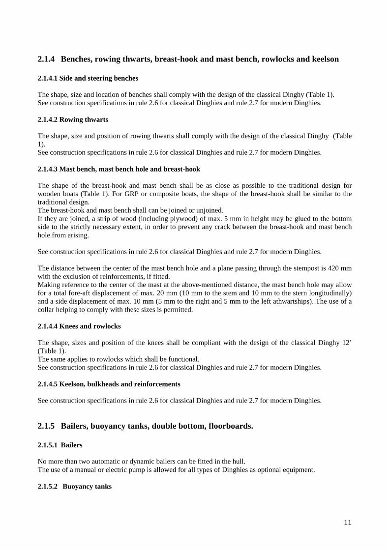
- Metallic strips or stiff materials are forbidden. Centerboard pivot: The pivot of the centerboard shall be made of stainless steel and measure 10 mm. It shall include a bush of 16 mm in outer diameter, with side rimming and washers to be fit between the nut and pivot head. The position of the center of the pivot shall be 1397 mm ± 20 mm from the plumb line of the stempost [equal to 2663 mm ± 20 mm + any length difference of the boat measured from the external vertical tangent to the measurement point of the transom], and 43 mm with ± 2 mm from the center of the pivot to the external connection of the keel to the hull (strakes).
13
namely 81 mm ± 2 mm from the keel bottom
or min. 73 mm from the keel bottom to the lower face of the pivot bush.
The centerboard pivot shall not move from the position recorded in the measurement certificate. Any change to the pivot position shall be recorded exactly in the measurement certificate. A mobile housing or a housing with several holes for the pivot are forbidden.

14
2.1.7 Mast step The mast step shall permit fore and aft movement of the mast. No other movement is permitted. See construction specifications in rule 2.6 for classical Dinghies and rule 2.7 for modern Dinghies. 2.1.8 Construction specifications for classical Dinghies and modern Dinghies. Rule 2.6 reports the construction specifications for classical Dinghies and rule 2.7 for modern Dinghies.

15
2.2 Rudder and Centerboard
2.2.1 Rudder The shape, size and tolerances of the complete rudder in a classical 12’ Dinghy shall comply with the design in construction plans (Table 3). The shape, size and tolerances of a rudder in a modern 12’ Dinghy shall comply with those of a classical Dinghy. The rudder head may have a different size from those in drawings. The use of market or self-made kits is permitted, provided the original design is complied with.
2.2.1.1 Blade
The "blade" is the immersed portion of a rudder. The blade of the rudder may be fixed or mobile (the latter only for modern Dinghies). In the case of a mobile blade, the use of a device (pin) is mandatory while racing, to prevent the immersion depth of the rudder from changing. The blade shall be made of solid wood or marine plywood and measure 22 ± 3 mm in thickness. The blade may be tapered down to max. 60 mm from the edges. The rudder head may depart from the sizes in the drawing, so that commercially available kits may be used. A wooden rudder head is mandatory in classical Dinghies. In any case, the immersed part of the rudder shall be built in accordance with construction plans (Table 3) and within the specified tolerances. The sail number and measurer’s stamp shall be carved in the blade.
2.2.1.2 Tiller and Stick
The tiller may be made of wood or metal and be of any size. An adjustable tiller extension is permitted. The construction material is free. A wooden tiller is mandatory in classical Dinghies. A pin preventing the tiller from escaping is mandatory.
2.2.1.3 Weight
The weight of the rudder, complete with tiller and stick, cannot be less than 4.0 kg.
2.2.1.4 Pintles and Gudgeons
The shape and position of pintles and gudgeons are free. The shape specified in Table 7 is recommended for classical Dinghies. The distance of the rudder to the transom, when the tiller is in the middle, shall be 40 ± 10 mm. If the distance of the traveler to the fixed tiller is not sufficient to prevent the rudder from being lost in the event of a capsize, it is mandatory to fit a retaining clip (or a similar fitting) next to the bottom pintle.
2.2.1.5 Position mark to the hull
A mark of 10 mm in thickness and 100 mm in length shall be traced in a discernible color on both sides of the rudder blade, whose lower edge shall be spaced from the tiller housing throat by 410 mm ± 20 mm. The aft measurement point, as defined in rule 2.1.2.1, shall fall between the two edges of the mark.

16
The position mark may be replaced with two marks in discernible colors, of 10 mm in thickness and 100 mm in length, whose lower edge shall be spaced from the blade housing throat by 410 mm ± 20 mm. The measurement point, as defined in rule 2.1.2.1, shall fall between these two marks. The max. height of the rudder from the tiller throat to the blade bottom, shall be 910 ± 20 mm.
2.2.2 Centerboard The shape and sizes of the centerboard are reported in construction plans (Table 4).
2.2.2.1 Sizes
- Total length 1163 mm - Total width 344 mm - Thickness 6 ± 0,5 mm - Length of exit edge 965 mm - Tapered length of exit edge 540 mm - Tapered width of exit edge 30 mm max. - Tapered width of lower edge 30 mm max. - Tapered width of entry edge 13 mm max. - Slope of upper and lower edges 30° - Height of the slot for the centerboard pivot 17. 4 ± 2 mm - Distance of the center of hole for centerboard pivot from entry edge 67 ± 2 mm - Diameter of the hole for centerboard rigging 8 mm 2.2.2.2 Weight and material
Material: steel or stainless steel.

17
Permitted coatings: zinc coating, painting and surface treatments to increase working life in immersion.
Weight: 15 ± 1.5 kg
2.2.2.3 Maximum extension
The maximum slope of the centerboard shall be 75° measured from the exit edge of the blade and the horizontal tangent to the keel. The lock preventing the centerboard from rotating more than permitted shall not be removed while racing. The lock shall beat against the centerboard case or onto stiff shims and fixed firmly on the centerboard case. Bumpers in rubber or a similar material may be fitted on the lock or shims and their thickness shall be added to the maximum rotation. In any case, the lowest point of the centerboard, while at maximum immersion, cannot be more than 820 mm, measured perpendicularly from the keel. Any use of the centerboard away from its housing is forbidden. It is mandatory to use to safety metallic hooks, whose thickness cannot exceed 2 mm, (See table 4) preventing the centerboard from escaping accidentally on capsizing. If the positioning of both metallic hooks is impossible, the fitting of a single hook having the mentioned thickness and sizes is permitted. It is also mandatory to use a stop (rope or elastic cord) fitted and blocked conveniently. It is permitted to replace the rope with an elastic cord of min. 8 mm in thickness, which shall be tensioned conveniently. The centerboard shall lower only by gravity (see rule 2.1.6).
820 mm
18
To prevent the centerboard from moving inside its case, two non-removable shims of Teflon or a similar material of max. 2 mm in thickness may be applied on each side of the centerboard on the non-immersed part. The thickness of these shims cannot be added to that of safety plates.
2.3 Spars The term spars includes: Mast, Boom and Gaff. These may be made of wood or aluminum alloy. Wooden spars may be hollow or solid and be made of several layers of different wood types. Their arrangement is free. The sizes of spars are specified in Table 5 and are inclusive of tolerances, if permitted. If constructed with aluminum alloy sections, the minimum thickness of the gaff and boom shall be 1.5 mm and that of the mast shall be 1.8 mm.

19
2.3.1 Mast Any movement of the mast shall not exceed ±10 mm longitudinally and ±5 mm transversally to the center of the mast bench hole that is located 420 mm from the stempost. No other movement is permitted. The mast can rotate inside the mast bench hole and move longitudinally only on the horizontal plane. Three protections for the mast of leather, GRP, PVC, nylon or rubber are permitted. Their max. length may be 400 mm each. Protections are not included in the measurement sections.
2.3.1.1 Mast sizes and profile
The mast shall have a measurement band (mark) in a discernible color of 20 mm in thickness, acting as and symbolizing tolerance, whose lower edge shall be 3307 mm from the bottom of the upper throat of the halyard pulley on the masthead, measured ahead of the mast. Only one pulley is permitted for the halyard. Although the use of a pulley is recommended, it may be replaced with any semicircular throated handiwork of steel or Teflon, having the same sizes as the pulley, where the halyard may only slide. In any case, the traction point of the halyard on the masthead shall always fall inside the mast. A slot may be produced on the front side of aluminum masts, from where the halyard can be pulled out. The upper plane of the mast bench hole shall fall inside the 20 mm size mark ahead.
Keeping the distance of 3307 mm from the bottom of the pulley to the front edge of the mast bench hole unchanged, the above measurement may be simplified by replacing the mark or adding a second mark in a discernible color, of 20 mm in height, acting as and symbolizing tolerance, whose lower edge shall be exactly 10 cm from the lower edge of the mark on the same level of the mast bench hole or, if erased, from the upper/front plane of the mast bench hole. As a result, the lower edge of the second mark shall be 3207 mm from the bottom of the halyard pulley. The cross section of the mast may be circular or elliptical. It is recommended that the mast construction is buoyant. If the mast is made of aluminum alloys, its thickness shall be uniform, however reinforcements of the same material as the mast are permitted. Weight shall be uniformly distributed. The diameter of the circular cross-section or the smaller axis of the elliptical cross-section shall range from 50 mm to 71 mm. The larger axis of the elliptical cross-section cannot exceed 71 mm.

20
If the mast is tapered, taper is permitted 1400 mm above the upper face of the mast bench, totaling 600 mm from the mast base. The mast can be tapered down to 50 mm in diameter.
2.3.2 Boom When in resting position, the boom shall be straight. The boom may incorporate a groove for the mainsail footrope, that shall be included in the maximum measurements of the boom. A leather, GRP, polyvinyl or rubber protection of max. 200 mm in length is permitted at the contact point with shrouds.
2.3.2.1 Boom sizes and profile
The cross-section of the boom is free, provided it falls in a circle of 52 mm in diameter. The boom may be tapered down to 119 mm at the gooseneck and 100 mm at the end.
Thickness shall be uniform but reinforcements are permitted, provided they are made of the same material as the boom. The boom shall be fixed to the mast at the tack by means of a jaw, the extremities of which are joined to each other by a strop; the inner distance between the two cheeks of the jaw shall not exceed 110 mm.
21
The boom shall incorporate a fixing system next to the tack on which a band of 10 mm shall be painted, whose aft edge shall correspond to the starting point of the sail body, inclusive of the luff cord, if fitted. A measurement band (mark) of 10 mm shall be painted at the end. It shall be at a distance of 3580 mm from the band at the tack, measured internally to the edges. The sail cannot be set up outside the inner edges of the two bands. The maximum height of sail trimming fittings shall be 50 mm.
2.3.3 Gaff The gaff shall be equipped with a fixing system for the sail luff that may be used to adjust the traction to the sail head. This adjustment may be made inboard. The maximum height of the fitting is 50 mm. The gaff may incorporate a groove for the luff, which may go beyond the outer diameter by no more than 18 mm.
2.3.3.1 Gaff sizes and profile
The cross-section of the gaff is free, provided it falls in a circle of 52 mm in diameter. Tapering, if any, shall be down to min. 119 mm at the ends. Thickness shall be uniform but reinforcements are permitted, provided they are made of the same material as the gaff. Two lines fixed to the bottom of the gaff are permitted, so that the gaff may be moved from one side of the mast to the other when sailing. The gaff may be joined to the mast by a strop, preventing the gaff from passing externally of the shrouds when gybing. The curve of the gaff shall be as even as possible, with a central camber of 51 ± 10 mm, measured in resting conditions between the inner edges of the measurement bands. The connection point for the halyard shall range from 1290 mm to 1510 mm. These sizes shall be measured internally to the fore measurement band and be marked by two measurement bands of 10 mm painted in a discernible color. The connection point for the halyard shall be such that under no circumstances the distance between the gaff and the passage point of the halyard exceeds 80 mm. The gaff shall incorporate two other measurement bands (marks) painted in a discernible color of min. 10 mm in width, whose maximum size is 3580 mm from the inner edges of the bands. The sail cannot be trimmed outside the external edges of the two bands.
22
2.4 Mainsail
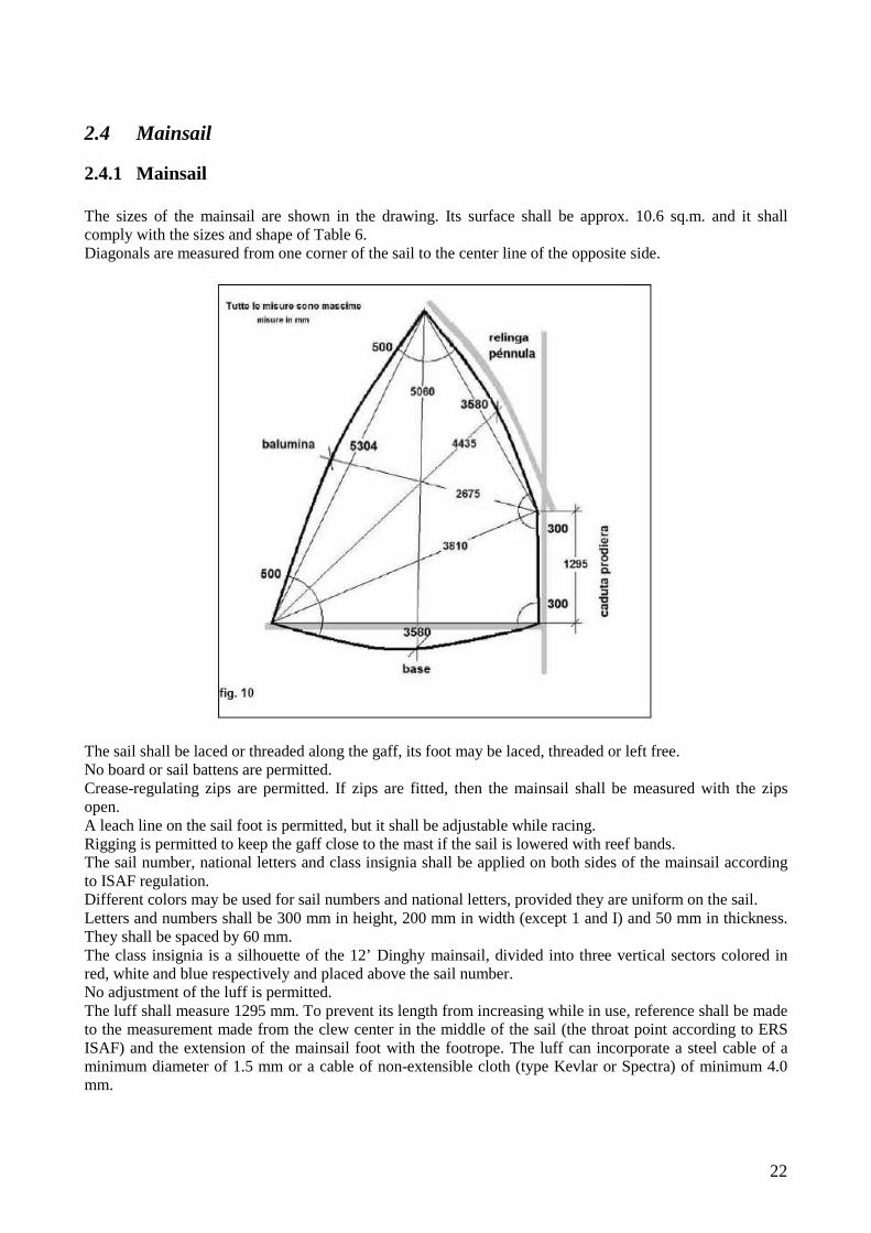
2.4.1 Mainsail The sizes of the mainsail are shown in the drawing. Its surface shall be approx. 10.6 sq.m. and it shall comply with the sizes and shape of Table 6. Diagonals are measured from one corner of the sail to the center line of the opposite side.
The sail shall be laced or threaded along the gaff, its foot may be laced, threaded or left free. No board or sail battens are permitted. Crease-regulating zips are permitted. If zips are fitted, then the mainsail shall be measured with the zips open. A leach line on the sail foot is permitted, but it shall be adjustable while racing. Rigging is permitted to keep the gaff close to the mast if the sail is lowered with reef bands. The sail number, national letters and class insignia shall be applied on both sides of the mainsail according to ISAF regulation. Different colors may be used for sail numbers and national letters, provided they are uniform on the sail. Letters and numbers shall be 300 mm in height, 200 mm in width (except 1 and I) and 50 mm in thickness. They shall be spaced by 60 mm. The class insignia is a silhouette of the 12’ Dinghy mainsail, divided into three vertical sectors colored in red, white and blue respectively and placed above the sail number. No adjustment of the luff is permitted. The luff shall measure 1295 mm. To prevent its length from increasing while in use, reference shall be made to the measurement made from the clew center in the middle of the sail (the throat point according to ERS ISAF) and the extension of the mainsail foot with the footrope. The luff can incorporate a steel cable of a minimum diameter of 1.5 mm or a cable of non-extensible cloth (type Kevlar or Spectra) of minimum 4.0 mm.
23
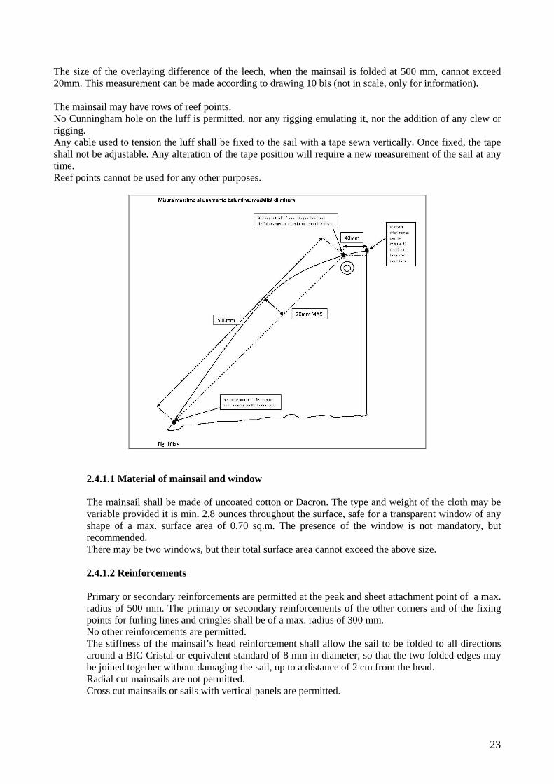
The size of the overlaying difference of the leech, when the mainsail is folded at 500 mm, cannot exceed 20mm. This measurement can be made according to drawing 10 bis (not in scale, only for information). The mainsail may have rows of reef points. No Cunningham hole on the luff is permitted, nor any rigging emulating it, nor the addition of any clew or rigging. Any cable used to tension the luff shall be fixed to the sail with a tape sewn vertically. Once fixed, the tape shall not be adjustable. Any alteration of the tape position will require a new measurement of the sail at any time. Reef points cannot be used for any other purposes.
2.4.1.1 Material of mainsail and window
The mainsail shall be made of uncoated cotton or Dacron. The type and weight of the cloth may be variable provided it is min. 2.8 ounces throughout the surface, safe for a transparent window of any shape of a max. surface area of 0.70 sq.m. The presence of the window is not mandatory, but recommended. There may be two windows, but their total surface area cannot exceed the above size. 2.4.1.2 Reinforcements
Primary or secondary reinforcements are permitted at the peak and sheet attachment point of a max. radius of 500 mm. The primary or secondary reinforcements of the other corners and of the fixing points for furling lines and cringles shall be of a max. radius of 300 mm. No other reinforcements are permitted. The stiffness of the mainsail’s head reinforcement shall allow the sail to be folded to all directions around a BIC Cristal or equivalent standard of 8 mm in diameter, so that the two folded edges may be joined together without damaging the sail, up to a distance of 2 cm from the head. Radial cut mainsails are not permitted. Cross cut mainsails or sails with vertical panels are permitted.
24
2.5 Rigging
2.5.1 Shrouds The mast shall be supported by two steel shrouds, one on each side, to be fixed to the masthead with the classical tang system, or with two steel arms, thimbles or pins. The shrouds shall be fixed at a distance from the masthead not exceeding 100 mm. The shrouds shall be fixed to the chain plates with turnbuckles, holed chain plates or lacing strops. Shroud adjustment while racing is not permitted. The use of steel ropes and Dyform ropes is permitted.
2.5.2 Chain plates The chain plates must be made of a metallic material and be strongly fixed to the hull, at 590 mm ± 20 mm from the tangent plane to the stempost, with the exclusion of any protection plate (see Table 1).
2.5.3 Traveler The traveler, along which the sheet block slides, shall be made of stainless steel, bronze or brass and be not less than 10 mm in thickness. It shall be fixed to the aft knees, if fitted, or to the transom. Running rigging may be used to adjust the block athwartships. The maximum height of the traveler, measured from the line passing through the upper face of the fenders and the lower surface of the traveler, shall be 95 mm ± 20mm in the middle, 79 mm ± 20 mm at the ends. The traveler and tiller may serve to hold the rudder in the case of a capsize.
2.5.4 Halyard The halyard may be made of steel, rope or a combination of both materials without stiffening elements. It shall be joined to the gaff through the upper throat of the masthead pulley, and it shall be led inboard through a block fixed to the stempost. The halyard shall also serve as forestay. Any blockage of the halyard on the masthead is forbidden. The adjustment of the halyard while racing is permitted.
2.5.5 Running rigging Permitted are: downhaul, clew outhaul fitting, vang, mast heel adjustment, centerboard adjustment, toe straps adjustment, mainsail halyard adjustment, transversal adjustment of traveler block, gaff boltrope adjustment inboard, adjustment of halyard fixing point on the gaff inboard, within the limits stated in rule 2.3.3.1. The running rigging can be fitted in any way, subject to the prescriptions of these rules. Complex and sophisticated equipment such as Kandahar tighteners, cams, mast ram close to the mast bench are forbidden. The sheet lead may be fixed to the boom at any point. The sheet shall leave from the boom, where it can be fixed through the first block. It shall go through the sliding block on the traveler and be led through the last block on the boom.
25
The use of a swivel jamming clamp fixed to the centerboard is permitted. It is permitted to add any rigging which is suitable to simplify boat righting operations in the event of capsizing. Riggings shall not be used to shift the ballast while racing.

26
2.6 Construction rules for Classical Dinghies
2.6.1 Hull All parts shall be constructed according to construction plans (Table 1). It is mandatory to use the prescribed wood types. The use of different wood types – provided they have similar characteristics to those specified and in particular Brinell hardness and specific weight (kg/cu.m.), shall require the prior written approval of the Class Authority following the builder’s justified written application. Approval shall be published on the Class website and extended to all builders. All wooden parts shall be made of solid wood.
2.6.2 Key measures See rule 2.1.1
2.6.3 Waterlines See rule 2.1.2
2.6.4 Hull details
2.6.4.1 - Keel
Material : Oak, Teak, Iroko, Douglas. Sizes: See rule 2.1.2.4 The keel can be constructed with two planks of solid wood, laminated and glued together longitudinally, with opposed fibers of the same wood type (Oak, Teak, Iroko, Douglas).
2.6.4.2 - Keelson
Material : Oak, Spruce, Teak, Iroko, Douglas Sizes: See rule 2.1.2.4 Fixing: Fixed to the keel with brass or stainless screws spaced by 100 mm. Screws next to the centerboard case shall be min. 75 mm in length and be built in the keel for max. 25 mm.
2.6.4.3 – Stempost and stem nose
Material : Oak, Iroko Sizes: Min. 45 mm thickness Shape: See Table 1 Fixing: Glued to the keel and then screwed or fixed with copper rivets.
27
Externally to streaks, the stempost and stem nose can be constructed with two planks in solid wood, laminated and glue together, with opposed fibers of the same wood type (Oak, Iroko). 2.6.4.4 - Sternpost
Material : Oak, Iroko Sizes: Min. 30 mm thickness Shape: See Table 1 – The sternpost and elbow can be manufactured out of one 30 mm piece without joints. Fixing: The sternpost may be built in the keelson and the elbow may be fixed with copper or stainless steel screws or copper nails.
2.6.4.5 - Transom
Material : Mahogany or Teak Sizes: See rule 2.1.2.1 Shape: See rule 2.1.2.1 Fixing: Screwed to the strakes and the sternpost
2.6.4.6 – Centerboard case
Material : Walls, Head filling, Cover Board: Mahogany, Oak, Teak, Iroko Sizes: See rule 2.1.6 Shape: The shape in Table 1 is recommended Fixing: Fixed with copper or stainless steel screws 7x75 mm every 125 mm. Two supports connecting the centerboard to the forward rowing thwart are permitted.
2.6.4.7 - Centerboard pivot
Material : See rule 2.1.6 Sizes: See rule 2.1.6 Shape: See rule 2.1.6 Fixing: See rule 2.1.6
2.6.4.8 – Planking
The planking shall be composed of 12 planks on each side, overlapped by 16 mm. The planks shall be planed along the lower beveling, with the exception of the ends, to ensure that the appropriate inclination is obtained and every plank fits the upper strake perfectly (mitre joint).
28
Outer edges cannot be rounded.
Material : Mahogany, Teak, Pine, Cedar, Larch Sizes: Planks of 8 mm in thickness. Shape: In compliance with rule 2.1.2 Fixing: Every plank shall be fixed to the timbers using one copper rivet and one rove. A minimum of two copper rivets and two roves must be fastened between each pair of timbers. This joint may be strengthened with marine, polyurethane or epoxy glue.
2.6.4.9 – Timbers
Timbers shall be parallel to the transom and possibly made of one piece from one gunwale to another. A filling wedge shall be placed between the garboard and the timber as required. The timber ends shall adhere perfectly to the gunwale or be built in it.
Material : Oak, Elm, Ash, Acacia, Locust Sizes: Thickness: 16 mm; distance between the middle points of the timbers 178 mm. However, the first and last timbers shall measure 228 mm to the outer tangent to the stempost and to the transom respectively. Quantity: 19 Shape: In compliance with rule 2.1.2 Fixing: One copper rivet and washer on each strake.
2.6.4.10 - Mast step
A socket may be provided in the mast step to house the mast heel or, in the case of a metal mast, a support may be screwed to the stem. Mast movement is according to rule 2.1.7
Material : Oak, Mahogany, Teak, Iroko Sizes: See Table 1 Shape: See Table 1 Fixing: Fixed and screwed to the stem. Keeping the height of the bow keelson unchanged (table 1), the mast step shall be fitted at a min. height of 430 mm from the upper and lower edges of the mast bench hole.
2.6.4.11 - Gunwale and rowlocks
At least two pairs of rowlocks shall be fixed to the gunwale, one of which shall be functional (See rule 2.1.4.4).

29
Material : Oak, Ash, Cedar, Iroko, Mahogany, Teak Sizes: 32 mm height x 25 mm width, fore and aft tapered at 20 mm Shape: See Table 1 Fixing: The gunwale shall be fixed to the strakes using brass or bronze screws; the rowlocks shall be screwed to the gunwale.
2.6.4.12 - Stringers
Material : Oak, Sitka spruce, same wood as planking Sizes: 30 x 10 mm (+/- 2 mm) Shape: 2 round millings Fixing: Screwed to every timber below the rowing thwarts throughout the hull length and along the external perimeter of the floorboards.
2.6.4.13 Rowing thwarts
Material : Mahogany or Cedar Sizes: 190 mm width, min. 20 mm thickness Shape: See Table 1 Fixing: Screwed to two knees of Oak, Ash or Cedar, minimum 20 mm in thickness at each end, screwed to the strakes with two screws.
2.6.4.14 – Mast bench and mast bench hole
Material : Mahogany or Cedar. Sizes: 200 x 20 mm; minimum 20 mm thickness The mast bench hole shall permit a total fore-aft displacement of the mast of max mm. 20 and a side displacement of max. mm.10. The use of a collar is permitted to comply with tolerances. The mast bench hole center shall be placed at mm 420 from the plane passing through the stem, reinforcement excluded. Shape: See rule 2.1.4.3 and Table 1 Fixing: Screwed to two horizontal knees of min. 20 mm in thickness and to the gunwale. Two vertical knees (pendants) are not mandatory. If fitted, they shall be made of oak or the same wood as the planking.
2.6.4.15 - Steering bench and side benches
Material :

30
Mahogany or Cedar Sizes: Min. 20 mm thickness Shape: See rule 2.1.4.1 and Table1 Fixing: Screwed to the aft rowing thwart by means of a support that is screwed to the transom. A Mahogany, Oak or Ash member athwartships shall be fitted ahead, below the steering bench, measuring 50x20 mm. The steering bench can be movable. Two props (one each side) below the side benches and one drawer are permitted.
2.6.4.16 – Breast hook
Material : Oak, Mahogany, Cedar, Iroko Sizes: Min. 20 mm thickness Shape: See Table 1 and rule 2.1.4.3 (may not be connected to the mast thwart) Fixing: Screwed to the gunwale and possibly to the mast bench.
2.6.4.17 - Horizontal stern knees
Material : Oak, Ash, Cedar, Iroko Sizes: Min. 20 mm thickness. Shape: See Table 1 and rule 2.1.4.4 Fixing: Fixed with copper rivets or screws to the gunwale and the transom 30 mm from the tangent plane to the upper face.
2.6.4.18 - Floorboards1
Material : Mahogany, Spruce, Ash, Teak, Sitka spruce Sizes: Min. 10 mm thickness. The forward flooring can be 19 mm in thickness Shape: See Table 1 and rule 2.1.5.4. The flooring can be altered to allow for the access to bailers and/or the positioning of a bilge pump. Fixing: All floorboards shall be lockable to avoid that they are lost on capsizing
2.6.4.19 - Keelson
Material : Oak, Mahogany, Iroko Sizes:
1 Following the meeting of partners’ resolution of 12 March 2011, the construction pursuant to art. 6.3 was reconfirmed. According to this decision, Classical Dinghies shall be measured and race being equipped with anything is included in construction plans (table 1), including all floorboards (stern, central and stem floorboards).
31
Min. 16 mm thickness Shape: Profiled and toothed to fit the shape of planking (see Table 1) Fixing: Fixed with a headless copper nail to any planking strake and with one rivet on each side.
2.6.4.20 - Fender
Material : Oak, Ash, Cedar, Sitka spruce, Teak Sizes: 22 x 22 ± 3 mm Shape: Rounded outside Fixing: Nailed or screwed to the gunwale externally to the first strake. 2.6.4.21 – Bilge keel Material : Oak, Teak, Iroko Sizes: See rule 2.1.2.2 Shape: See Table 1 and rule 2.1.5.4 Fixing: Screwed to the strake
2.6.4.22 - Connecting materials
Copper rivets. Stainless steel, bronze or brass bolts, nuts and screws. Epoxy or polyurethane marine glue.

32
2.7 Construction rules for Modern Dinghies
2.7.0 Foreword The modern 12’ Dinghy is an evolution of the classical 12’ Dinghy as far as materials, building techniques and sailing safety devices are concerned. A modern 12’ Dinghy shall maintain the qualities of Cockshott’s design in terms of sturdiness, cheapness and useful life. When used for racing, its performance shall be comparable to that of a classical 12’ Dinghy to which the following rules make wide reference. For anything not included in the following rules, please refer to the regulation for classical Dinghies and to the relevant drawings. A modern 12’ Dinghy may be made of: GRP/wood GRP Glued construction in marine plywood or solid wood The boat may have a total, partial or no double bottom. It may be totally or partially made of GRP. Any builder wishing to construct a Modern 12’ Dinghy shall submit an application for construction license to the AICD authority, complete with drawings and a technical report.
2.7.0.1 - Hull of GRP/wood or only GRP. The moulds used for a 12’ Dinghy shall require the prior approval of the AICD authority. A mould may be only constructed using an approved, non-amnestied 12’ Dinghy hull as a model, provided it is conforming to the sizes, tolerances and outlines stated in construction plans and to the prescriptions of these rules. The final approval of the mould and the hulls produced with it may be issued following the approval of a complete prototype, having been inspected and approved by the Class Technical Committee. Waterlines shall be checked using the official Class Templates and Set Irons. Following the Class Authority’s final approval, the builder is entitled to issue a statement of conformity where he declares that all subsequent boats are conform to the approved prototype. Any alteration of the mould will require a new AICD approval and a new statement of conformity. The construction of a mould using a model of 12’ Dinghy is permitted only when the model has been approved and its conformity to construction plans, waterlines and these construction rules has been checked successfully by the Class Technical Committee. 2.7.0.2 - Double bottoms and buoyancy tanks
The double bottom and buoyancy tanks shall be approved by the AICD Technical Committee. The double bottoms shall be such that complete inspection is made possible. Any arrangement of the double bottom shall require the prior approval of the AICD Technical Committee.

33
1 – for boats produced with mould The builder shall submit all preliminary drawings to the Technical Committee for approval. After that, the builder may start the construction of a mould under the supervision of the Technical Committee, who shall be allowed to inspect work progress at any time for compliance with approved drawings. When the first boat has been approved, the builder will receive a measurement certificate from the AICD. 2 – for prototypes The builder shall submit construction drawings to the Technical Committee for approval. After that, the builder may start construction under the supervision of the Technical Committee, who shall be allowed to inspect work progress at any time for compliance with approved drawings. 3 – for approved boats Design and alteration drawings shall be submitted to the Technical Committee for approval. Any alteration will involve a re-measurement by a licensed FIV Measurer who shall issue a new certificate. The new certificate shall report the location where the boat was altered with respect to the approved design and describe the alteration made. 4 – walkable surface No point of the horizontal plane (extrados) of the double bottom shall exceed the level of the horizontal plane passing through the line joining level 340 mm next to section "D" and level 340 mm on the transom (see Tables 2a and 2b). 5 – fixed or structural buoyancy tanks Watertight tanks can be fitted under the steering bench and rowing benches, below the aft bench, astern and on one side of the mast step and in the extension of the side benches ahead. It is forbidden to alter the bending radius of benches next to the rowing seat for the purpose of increasing the volume of tanks. The builder shall guarantee that there are at least three separate watertight rooms between the double bottoms and buoyancy tanks, so that, if the volume of each of them is deducted from the total volume, the remaining volume is at least 140 liters. If this condition is not met, then foamy buoyancy tanks or inflatable tanks shall be fitted below the benches and in fore extensions, totaling 140 liters. 6 – Walkable surface In any case, the minimum floor area surface of the double bottoms shall not be smaller than 215 dm2. 2.7.0.3 - Material Boat construction material: GRP composed of Matt or biaxial and uniaxial glass fiber and polyester, vinyl ester or epoxy resin. Composite Kevlar, carbon or boron are forbidden. Vacuum construction of the boat is forbidden. Baking during construction is forbidden. The hull stratification (inclusive of gel coat) shall be monolithic, 2.5 mm in thickness and uniformly distributed. The coat may be thicker next to Matt overlapping (max. 5 mm with + 1 mm tolerance), near the stempost and the keel, and in the restricted areas of the connection of the centerboard case with the hull, the double bottom, the bulkheads in the double bottom and the permitted reinforcements, as well as in the cockpit. A dynamic bailer may be fitted in the cockpit in the boats provided with double bottoms. The thickness of the hull may be higher than the size stated in the prior paragraph if needed to level off the Matt sheet and the resin layer on the clinker edges.

34
A row wire can be fitted on the outer edge in order to prevent the gel coat from breaking out (and being repaired) on opening the mould. It is forbidden to increase thickness only to the purpose of distributing the weight of the hull differently or to level off the irregularities of the clinker inside the hull. Double bottoms may be made of Cadorite or a similar foamy material, of max. 15 mm in thickness. In this case, the minimum thickness of GRP shall be 1. 5 mm for each one of the two coats. 2.7.0.4 – Reinforcements and bulkheads The use of Omega reinforcements is permitted.
Two fore and aft Omega reinforcements may be used, of a max. size of 100 mm in width and 50 mm in height. Max. 2 athwartships bulkheads (4 semi-bulkheads if placed across the centerboard case) made of GRP or wood of max. 16 mm in thickness are permitted, which will also serve as watertight partition for the double bottoms. They may be made of GRP or wood or marine plywood. In the boats where the double bottom extends astern, it is possible to install an additional bulkhead of 16 mm in thickness – either athwartships or longitudinally – above the keel astern, that will serve support the double bottom. If the aft double bottom is provided with a large, deep, walkable cockpit, this additional bulkhead is not permitted.

35
2.7.0.5 – Reinforcements for fittings In order to guarantee the water tightness of screws and through pins, it is permitted to fit horizontal wooden reinforcements and/or steel plates or bushes either resin bonded or glued in the double bottom, in those areas where the fittings (blocks, sheet clamps, mast step….) are installed, which are subject to special wear or stress. These reinforcements are permitted only around the fittings and they cannot be used to support the double bottom. 2.7.0.6 – Reinforcement below the mast bench Only one reinforcement for the double bottom is permitted below the mast bench. It may be fitted athwartships for mm 300, or cross-shaped for max. 300 x 300 mm, or inside the keel from the centerboard case to the stempost. Its height shall extend up to the connection with the double bottom. It may be made of GRP or wood of maximum 16 mm in thickness. 2.7.0.7 - Timbers, stern, elbow (stern post), keelsons These elements are not necessary in GRP boats so their use is forbidden. The rigging for the floorboards is permitted where there are no double bottoms and it shall be fixed to the keelsons. 2.7.0.8 - Keelsons If fitted, keelsons shall be made of resin-bonded GRP or wood or marine plywood. They shall be max. 16 mm in thickness and max. 70 mm in height according to the drawings for a classical Dinghy 12’ (Table 1). Regarding their arrangement and number:
36
- their installation below a total or partial double bottom is forbidden, because the 2 bulkheads (4 semi-bulkheads ) already fulfill the function
- they are also forbidden in the area without double bottom where there are no side and/or aft watertight tanks
- they are mandatory in the uncovered areas of the boats with partial double bottoms, where the hull is at sight and there are no side and/or aft watertight tanks. They shall be toothed to suit the planking. 2.7.0.9 - Floorboards Floorboards shall be constructed:
- according to rule 2.6.4.18 in the boats without double bottoms; - only in the areas without a double bottom for the boats with partial double bottoms - they are optional in the boats with total double bottoms.
In any case, they shall be fixed conveniently to the hull. 2.7.0.10 - Keel Sizes are according to rule 2.1.2.4. Wall thickness (5 mm max.) shall not be such that the keel exceeds the weight of a wooden keel. The inner space of the keel may be filled with floating material having a max. total weight of 1.5 kg. 2.7.0.11 - Stempost and stem nose Sizes are according to the drawings for a classical 12’ Dinghy (Table1). The upper portion of the stempost can contain a wooden core (prescribed hard wood, such as Iroko or Oak) or even a metallic core that will end in the stem nose. 2.7.0.12 - Centerboard case The centerboard case shall be constructed according to rule 2.1.6 . If made of wood, it shall be conforming to the specifications for classical Dinghies. If made of GRP, its wall sizes shall be equal to those of a classical Dinghy. To obtain this thickness, it may be constructed with Cadorite or a similar expanded foam. It may be coated with wood. Only in the boats without double bottoms, it may be connected to the fore rowing seat with two pendants. 2.7.0.13 - Planking The hull sides shall be constructed according to rule 2.1.2.2 2.7.0.14 - Mast step It shall be made of metal and be fixed to or built in the double bottom or keel (see rule 2.1.7). 2.7.0.15 – Bilge keels See rule 2.1.2.2

37
2.7.1 GRP/wooden boats The reinforcements of the transom, benches, rowing thwarts, mast bench, breasthook, knees, gunwale/ fender/rowlock shall be made of wood. In boats made of a combination of GRP and wood it is forbidden to fit any fender, gunwale, benches, rowing thwarts, mast bench and breasthook that are made of GRP. Anything not specified in this paragraph about the above-mentioned parts can be found in the drawings and the prescriptions of rule 2.6 for classical Dinghies.
2.7.1.1 - Transom Sizes and shape: See rule 2.1.2.1 Tolerance for the transom is -5+10 mm on the size of 844 mm. Thickness of GRP: Max. 5 mm. Material: The inner side of the transom shall be totally or partially lined with wood (Mahogany, Cedar or Teak). It is permitted to install a plywood reinforcement on the lower pintle of the rudder. 2.7.1.2 – Side and steering benches and rowing thwarts Material: Mahogany or Cedar, also multi-layered Sizes: Same as in classical boats Shape: See Table 1 The boats with double bottom are granted a tolerance of minus 30 mm on the distance of the bench and rowing seat plane to the gunwale. Similarly to classical Dinghies, a transom measuring 50 x 20 mm may be fitted below the steering bench. 2.7.1.3 – Mast bench and mast bench hole Material : Mahogany or Cedar, also multi-layered Sizes: 200 x 20 mm; min. 20 mm thickness The mast bench hole shall permit a fore-aft displacement of the mast of max. 20 mm and a side displacement of max. 10 mm. It is permitted to use a collar to fit these tolerances. The middle point of the hole shall be positioned 420 mm from the plane passing through the stempost, reinforcement excluded. Shape: See rule 2.1.4.3 and Table 1 Fixing: Fixed to two horizontal knees of min. 20 mm in thickness and to the gunwale. Two vertical knees (pendants) are permitted only in the boats without a double bottom and, if fitted, they shall be made of Oak, Mahogany or Cedar.

38
2.7.1.4 - Breasthook Material : Oak, Mahogany or Cedar, also multi-layered Sizes: Min. 20 mm thickness Shape: See Table 1 and rule 2.1.4.3 Fixing: Fixed to the gunwale and possibly to the mast bench. 2.7.1.5 – Horizontal knees astern Material : Oak, Ash or Cedar Sizes: Min. 20 mm thickness Shape: See Table 1 and rule 2.1.4.4 Fixing: Fixed to the gunwale and the transom, 30 mm from the tangent plane to its upper face. 2.7.1.6 – Vertical knees of rowing thwarts Material : Oak, Ash or Cedar Sizes: Min. 20 mm thickness Shape: See Table 1 and rule 2.1.4.4 Fixing: Two knees on each side of every rowing seat 2.7.1.7 - Gunwale and rowlocks At least one pair of functional rowlocks shall be fixed to the gunwale next to each rowing seat (See rule 2.1.4.4). Material : Oak, Ash, Cedar, Teak Sizes: 32 mm height x 25 mm width, with a 20 mm fore and aft tapering Shape: See Table 1 2.7.1.8 - Fender Material : Oak, Ash, Cedar, Teak Sizes: 22 x 22 ± 3 mm Shape: Rounded externally

39
2.7.2 Wholly GRP boats Wholly GRP boats cannot include any fender, gunwale, benches, rowing thwarts, mast bench and breasthook that are made of wood. Purely for cosmetic purposes, it is permitted to veneer these parts with wooden strips or to overlap or fix wooden strips to the GRP layer. These strips, of max. 3 mm in thickness and max. 10 mm in width, cannot serve as structural reinforcement and cannot be removable in any way.
2.7.2.1 - Transom Sizes and shape: See rule 2.1.2.1 Tolerance for the transom is -5 +10 mm on a size of 844 mm. Thickness of GRP layer: Max. 5 mm. The double bottoms shall overlap on the transom: their total thickness shall be up to 10 mm. Material : It is permitted to install a resin-bonded plywood and/or foam reinforcement to the transom next to rudder pintles. 2.7.2.2 – Mast bench and mast bench hole Material : GRP or the same material as the rowing thwarts. Sizes: Min. 5 mm thickness if made of GRP or 15 mm if of the same material as the rowing seat. The mast bench hole shall allow a total fore-aft displacement of the mast of max. 20 mm and side displacement of max.10 mm. It is permitted to use a centering bush to fit these tolerances. The middle point of the hole shall be 420 mm from the plane passing through the stempost, reinforcement excluded. Shape: See Table 1 and rule 2.1.4.3 The horizontal knees between the mast bench and gunwale shall be integrated in the bench. Their thickness and material shall be the same as those of the bench. Their sizes shall comply with the drawings as closely as possible. Fixing: Two vertical knees (pendants) are permitted only in the boats without a double bottom and, if fitted, they shall be made of GRP and be of the same thickness as the stull. 2.7.2.3 - Breasthook Fitted in the double bottom in the point were it joins the hull. Material : GRP Sizes and Shape: See Table 1 and rule 2.1.4.3 (it may not be connected to the mast bench), as similar as possible to the breasthook of the classical Dinghy. 2.7.2.4 - Side and steering benches and rowing thwarts Material :

40
Cadorite, or a similar foamy material Sizes: Min. 15 mm thickness If integrated in the double bottoms, the minimum thickness of horizontal parts shall not be less than 2.5 mm. Shape: See Table 1 Boats with double bottoms are permitted a tolerance of minus 30 mm on the distance of the bench and rowing thwart plane to the gunwale. 2.7.2.5 – Vertical knees of the rowing thwarts Material : GRP Sizes and Shape: See Table 1 and rule 2.1.4.4 They shall be as similar as possible to the knees of classical Dinghies. Fixing: Two knees on each side of every rowing seat 2.7.2.6 - Traveler Material : See rule 2.5.3 Sizes and Shape: See Table 8 and rule 2.5.3 Fixing: Rather than on the knees, the mainsheet traveler may be fitted on the farther joint of the hull to the double bottom, however not more than 10 mm beyond the transom; in this case its maximum height shall comply with the sizes in rule 2.5.3. 2.7.2.7 - Gunwale fender and rowlocks At least one pair of functional rowlocks shall be fixed to the gunwale next to every rowing thwart (See rule 2.1.4.4). Material : GRP Sizes: Max. 10 mm thickness, where the hull joins the double bottom Shape: The shape and sizes (width and height) of the gunwale and fender in wholly GRP boats shall be similar to those in GRP/wooden boats. These parts can be integrated in the double bottom where it joins the hull. 2.7.2.8 – Stem nose The stem nose of wholly GRP boats may have a slightly different shape from that in the drawings. However, the block connection to the halyard block shall be placed internally, as according to drawings.

41
2.7.3 – Glued boats of marine plywood or solid wood The hulls made of wood or marine plywood may be constructed according to modern boat specifications. However they may not be classified as “classical”. They may be built with a total or partial double bottom or without a double bottom. Common rule: The hull may be constructed with marine plywood or solid wood. Marine plywood, of the types prescribed in the individual rules, is only permitted for plywood hulls. The use of GRP for the elements of the hull and double bottoms is forbidden in these boats. 2.7.3.1 - Hull details
2.7.3.1.1 - Keel Material : Oak, Teak, Iroko, Douglas. Sizes: See rule 2.1.2.4 Fixing: The same as classical Dinghies and/or epoxy, marine or polyurethane glue. The keel can be constructed with two planks in solid wood, laminated and glued together longitudinally, with opposite fibers of the same wood type (Oak, Teak, Iroko, Douglas) 2.7.3.1.2 - Keelson Material : Oak, Spruce or Teak, Iroko, Douglas Sizes: See rule 2.1.2.4 Fixing: Fixed to the keel with brass or stainless steel screws spaced 100 mm. On the centerboard case, the min. length of screws shall be 75 mm and they shall be embedded in the keel for max. 25 mm and/or fixed with epoxy, marine or polyurethane glue. 2.7.3.1.3 - Stempost and stem nose Material : Oak, Iroko Sizes: 45 mm min. thickness Shape: See Table 1 Fixing: Screwed or fixed to the keel with copper rivets or glued with epoxy, marine or polyurethane glue. The stempost and stem nose can be constructed with two planks in solid wood, laminated and glued together longitudinally, with opposite fibers of the same wood type (Oak, Iroko). 2.7.3.1.4 - Stern Material : Oak, Iroko Sizes:

42
Min. 30 mm thickness Shape: See Table 1 – The stern and elbow may be a monobloc piece of 30 mm without joints. Fixing: Embedded in the keelson. The elbow shall be fixed with copper or stainless screws or with copper nails and/or glued with epoxy, marine or polyurethane glue. 2.7.3.1.5 - Transom Material : Mahogany, Teak. Sizes: See rule 2.1.2.1 Shape: See rule 2.1.2.1 Fixing: Screwed to the strakes and the stern and/or glued with epoxy, marine or polyurethane glue. 2.7.3.1.6 – Centerboard case Material : Sides, head filler, cover board: Mahogany, Oak, Teak, Iroko Sizes: See rule 2.1.6 Shape: Recommended in Table 1 Fixing: Copper or stainless steel screws of 7x75 mm every 125 mm, and/or epoxy, marine or polyurethane glue. 2.7.3.1.7 - Centerboard pivot Material : See rule 2.1.6 Sizes: See rule 2.1.6 Shape: See rule 2.1.6 Fixing: See rule 2.1.6 2.7.3.1.8 – Planking The planking shall be composed of 12 planks on each side, overlapped by 16 mm. The planks shall be planed along the lower beveling, with the exception of both ends, so that the appropriate slope is obtained to make them adhere perfectly to the upper strake (mitre joint). Outer edges cannot be rounded. Material : Mahogany, Teak, Pine, Cedar, Larch Sizes: Planks of 8 mm in thickness. Shape: In compliance with rule 2.1.2
43
Fixing: Every plank shall be fixed with one copper rivet and one rove to the timbers, if fitted. Strakes shall be bonded only with marine, polyurethane or epoxy glues. 2.7.3.1.9 - Timbers The builder may omit the construction of timbers. In this case, no timbers at all shall be constructed. Material : Oak, Elm, Ash, Acacia, Locust Sizes: See rule 2.6.4.9 Shape: See rule 2.6.4.9 Fixing: See rule 2.6.4.9 2.7.3.1.10 - Mast Step A hollow may be provided to house the mast heel or alternatively a support may be screwed in place for a metal mast. Mast displacement is according to rule 2.1.7 Material : Oak, Mahogany, Teak, Iroko Sizes: Recommended those in Table 1 Shape: Recommended those in Table 1 Fixing: Screwed to the stem or embedded in boats having double bottoms. 2.7.3.1.11 - Gunwale and rowlocks At least one pair of functional rowlocks shall be fixed to the gunwale (rule 2.1.4.4). Material : Oak, Ash, Cedar, Iroko, Mahogany, Teak Sizes: See rule 2.6.4.11 Shape: See rule 2.6.4.11 Fixing: See rule 2.6.4.11 2.7.3.1.12 - Stringers If the boat has a double bottom, the builder may omit the construction of stringers to support the floorboards. Floorboards are mandatory in boats without a double bottom and they shall be fixed to the keelsons (if stringers are not fitted). Material : Oak, Sitka spruce, same wood as planking Sizes:

44
See rule 2.6.4.9 Shape: See rule 2.6.4.9 Fixing: See rule 2.6.4.9 2.7.3.1.13 - Rowing thwarts, steering bench and side benches Boats having a double bottom are granted a tolerance of minus 30 mm on the distance of the rowing seat and steering bench plane to the gunwale. Material : Mahogany or Cedar Sizes: See rules 2.6.4.13 and 2.6.4.15 Shape: See rules 2.6.4.13 and 2.6.4.15 Fixing: See rules 2.6.4.13 and 2.6.4.15 2.7.3.1.14 – Additional hull details The size and thickness of all the following details shall be conforming to rule 2.6 – Construction rules for classical Dinghies. They shall be fixed as prescribed for classical boats and/or glued with epoxy, marine or polyurethane glue. Prescribed woods are: Mast bench: Mahogany or Cedar; Pendants of boats without double bottoms: same wood as for strakes. Breasthook: Oak, Mahogany, Cedar or Iroko Horizontal knees and rowing thwarts: Oak, Ash, Cedar, Iroko Floorboards, if fitted: Mahogany, Spruce, Ash, Teak or Sitka spruce Keelsons: Oak, Mahogany or Iroko Fender: Oak, Ash, Cedar or Sitka spruce, Teak Bilge keel: Oak, Teak or Iroko 2.7.3.1.15 - Buoyancy tanks for boats without double bottoms and fixed buoyancy tanks See rule 2.1.5.2 - Buoyancy tanks. 2.7.3.1.16 - Double bottoms and fixed buoyancy tanks The double bottom and fixed buoyancy tanks shall be approved by the AICD Technical Committee. Any arrangement of the double bottom shall require the prior approval of the Technical Committee. Material : The double bottoms and fixed watertight tanks shall be made of wood (marine plywood for plywood hulls), of minimum 6 mm in thickness, and minimum 140 liters in volume and divided into at least three compartments.

45
1 – for prototypes The builder shall submit construction drawings to the Technical Committee for approval. After that, the builder may start construction under the supervision of the Technical Committee who shall be allowed to inspect work progress at any time for compliance with approved drawings. 2 – for approved boats Design and alteration drawings shall be submitted to the Technical Committee for approval. Any alteration will involve a re-measurement by a licensed FIV Measurer who shall issue a new certificate. The new certificate shall report the location where the boat was altered with respect to the approved design and describe the alteration made. 3 – walkable surface No point of the horizontal plane (extrados) of the double bottom shall exceed the level of the horizontal plane passing through the line joining level 340 mm next to section "D" and level 340 mm on the transom (see Table 2c) 4 – buoyancy tanks Fixed and/or structural tanks may be fitted under the rowing thwarts, below the steering bench, astern and on one side of the mast step and in the extension of the side benches ahead. It is forbidden to alter the bending radius of benches next to the rowing seat only to the purpose of increasing the volume of tanks. The builder shall guarantee that there are at least three separate watertight tanks between the double bottoms and buoyancy tanks, so that, if the volume of each of them is deduced from total volume, the remaining volume is at least 140 liters. 5 – walkable surface. In any case, the minimum walkable surface of the double bottoms shall not be smaller than 215 dm2. 2.7.3.1.17 - Bulkheads Max. 2 bulkheads (4 semi-bulkheads if placed across to the centerboard case) of max. 16 mm in thickness made of Oakor Mahogany are permitted in order to support the double bottoms. They shall be screwed or glued with epoxy or marine glue and they shall serve as watertight partition for the double bottoms. They may be made of wood or marine plywood for plywood hulls. In the boats whose double bottom extends astern, it is possible to install an additional bulkhead of 16 mm in thickness above the keelson, either athwartships or to the fore-aft direction, in order to support the double bottom. In the boats where the double bottom extends astern, it is possible to install an additional bulkhead of 16 mm in thickness athwartships or to raise the keel (tapered down to 16 mm) astern in order to support the double bottom. If the aft double bottom is provided with a large, deep, walkable cockpit, these bulkheads are not permitted.

46
2.7.3.1.18 – Reinforcements for fittings In order to guarantee the water tightness of screws and through pins, it is permitted to fit horizontal wooden reinforcements and/or steel plates or bushes either resin bonded or glued in the double bottom, in those areas where the fittings (blocks, sheet clamps, mast step….) are installed, which are subject to special wear or stress. These reinforcements are permitted only around the fittings and they cannot be used to support the double bottom. 2.7.3.1.19 - Reinforcement below the mast step Only one reinforcement below the mast step is permitted in the boats provided with a double bottom. It may be fitted athwartships for 300 mm or cross-shaped for max. 300 mm x 300 mm, or to the fore-aft direction from the centerboard case to the stempost/stem nose. These reinforcements shall be fitted above the keelson/stempost/stem nose and be joined to the double bottom with screws or epoxy, marine or polyurethane glue. Material: Oak, Mahogany, Iroko. 2.7.3.1.20 - Keelsons They shall be max. 16 mm in thickness, made of Oak and Mahogany and screwed according to the prescriptions for classical Dinghies and/or glued with epoxy, marine or polyurethane glue.
- Their installation below total or partial double bottoms is forbidden, because the 2 bulkheads (4 semi-bulkheads ) already fulfill the function
- They are mandatory in the boats with partial double bottoms in the uncovered areas where the hull is at sight and there are no side and/or aft watertight tanks. They shall be toothed to suit the planking and their arrangement and number shall be according to drawings. 2.7.3.1.21 – Connecting materials Copper rivets. Stainless steel, bronze or brass bolts, nuts and screws. Epoxy or polyurethane marine glue.

47
3. CONSTRUCTION PLANS The following construction plans are attached to these Rules: Table 1) - HULL - Waterlines and specifications for classical hulls
Table 1a) Hull and centerboard case Table 1b) Sections A; B; C; D and transom Table 1c) Stempost and stem nose; Sternpost
Table 2) – DOUBLE BOTTOMS AND INNER HULLS
Table 2a) double bottoms and inner hulls of GRP/wooden boats Table 2b) double bottoms and inner hulls of wholly GRP boats Table 2c) double bottoms and inner hulls in modern, double-bottom wooden boats
Table 3) – RUDDER - Shape and sizes Table 4) – CENTREBOARD - Shape and sizes Table 5) – SPARS - Shape and sizes Table 6) – MAINSAIL - Shape and sizes Table 7) – FITTINGS (classical Dinghies)

48
4. MEASUREMENT RULES
4.0 General Measurements shall be taken by an official Measurer, holding a license for the 12’ Dinghy Class, charged by the boat owner. The boat owner shall be registered with FIV, AICD and have applied for a sail number according to the procedure stated in rule 1.6 The Measurer shall complete each part of the Measurement Certificate (see rule 5.1.7), sign it and send it to the Class Secretary who will issue an official Measurement Certificate. If there are doubts about a measuring mistake, the omission of important information or the infringement of these rules, the Class Authority may refuse to issue a Measurement Certificate. On these circumstances, the Class Authority shall soon inform the boat owner, the measurer and the builder and call a meeting of the Technical Committee for a re- examination, the outcome of which shall be entered in the report to be sent to the Class Secretary. Any rule interpretation by the Technical Committee concerning a 12’ Dinghy measured by an official Measurer who is a member of the Technical Committee shall be endorsed by another measurer to be designated by the Class Authority or the Race Committee for protests. At the end of procedures, the Measurer shall set his stamp reporting his FIV identification number in compliance with rule 1.9
4.1 Hull Measuring Procedures The length of the hull shall be measured with the exclusion of aft fittings and the stempost protection, if fitted. The width of the hull shall be measured excluding the fender.
4.1.1 Hull weight The weight of the hull shall be measured only including the fittings fixed to the hull and any floorboards (if fitted, they shall be reported in the measurement certificate) as well as running rigging. The rudder with tiller and stick shall be included; the rows, rowlocks, spars, centerboard, sail sheet, halyard, towing rope and removable buoyancy tanks shall be excluded. The minimum weight may include the metallic strips fixed under the keel and on bilge keels, of a maximum weight of kg. 2. The hull thus equipped shall weigh 115 kg. If weight ranges between 108 kg and 111 kg, it shall be adjusted with the addition of lead ballast, that shall be fixed in a non-removable way to the steering bench at contact with the transom. The Measurer shall be responsible for sealing the ballast and fixing devices with a seal bearing the official FIV stamp. The addition of ballast shall be detailed in the measurement report and certificate.

49
If the weight of the boat is less than 108 kg, the boat cannot be approved.
4.1.2 Swing test
4.1.2.1 – Boat preparation for swing test The 12’ Dinghy shall be prepared for swing test by: - draining all water from the keel or the double bottoms, if fitted; - removing the centerboard and rudder; - removing all removable fittings (tiller, mast, sails, gaff, sail sheet, paddle, bailer); - placing the centerboard rigging in middle position, and - removing the turnbuckles. 4.1.2.2 – Center of gravity The vertical line of the center of gravity shall fall in the upper half of the hull (measured from the keel bottom to the gunwale), in the longitudinal position of the center of gravity. If the vertical position of the center of gravity is incorrect (e.g. in the lower half of the hull), it shall not be corrected with weights and the boat cannot be approved. The longitudinal position of the center of gravity shall range from 1600 to 1750 mm from the reference plane of the transom. The vertical and longitudinal positions of the center of gravity shall be reported in the measurement certificate in the section named "Notes of the Measurer" (see annex A7). 4.1.2.3 - Radius of gyration The longitudinal radius of gyration of the hull shall not be less than 970 mm. The radius may be corrected with weights, as said above, which may be added to hull corrector weights (rule 2.1.3.2) . The corrector weights used to adjust the minimum weight, the position of the center of gravity and the radius of gyration shall not exceed 6 kg. If anyone of the requirement (i.e. weight, center of gravity or radius of gyration) is not met after the application of corrector weights, the boat shall not be approved. After the approval date of these rules, the radius of gyration of all new and/or never measured boats shall be reported in the measurement certificate in the section named "Notes of the Measurer" (see annex A7). 4.1.2.4 – Derogations to the measurement of the center of gravity and radius of gyration Sample measurements of the center of gravity and radius of gyration may be taken for information/statistic purposes on any Dinghies that on the date of approval of these rules are already provided with a measurement certificate. 4.1.2.5 – Description of swing test gear and test procedure The swing test gear is composed of a fixed set including a metallic frame of at least 2 m in width and 1.2 m in height, measured from the swing center. An additional frame may be used to simplify weight measurement. Another needed instrument will be a stopwatch or ultrasound probe which, being connected to a PC with special software, can measure the period of oscillation with an accuracy of at least one tenth of a second. This instrument, named Go Motion, shall be placed astern below the keel.

50
The Dinghy shall be placed in balanced position with the transom orthogonal to the base line, namely the parallel to the floor in level. The swing test shall be carried out in accordance with procedure P001 which prescribes the measurement of the distance of the swing center from the stern (longitudinal position of center of gravity) and the measurement of oscillation periods at two different points from the swing center. Thus, by applying the formulas stated in the above procedure, one can obtain the position of the radius of gyration, i.e. the longitudinal distance from the swing center where the fore and aft mass of the boat is concentrated, as well as the vertical distance of the center of gravity to the keel. The outcome of the swing test shall be reported in the form annexed to procedure P001, named PendPad.01. 4.1.3 – Measurement of the hulls of wooden Dinghies The following steps shall be carried out to check boat waterlines:
a) The hull shall be placed with the keel upwards. The baseline shall be marked using section A
with respect to the planking at the transom and size I with respect to the keel at the stempost. b) The 17 sections reported in the original drawings shall be positioned starting from astern and
numbered in such a way that the transom is no.17. The distance between the sections shall be 216 mm from section 17 to section 1. The distance of section 1 to the stempost shall be 204 mm.
c) The odd sections of point “b” shall be marked on the baseline. Two sets of measurements shall be taken in these sections: one marked S to L, between the baseline and keel bottom; another marked B to H, between the keel bottom and inner planking (if the outer planking is measured, use the sizes stated in Table 1, less 8 mm).
d) If measurements do not comply with tolerances, re-measurements shall be carried out. The baseline shall be set after changing the values of A and I, provided they are inside the tolerances prescribed.
e) Width of the keel: see rule 2.1.2.4 f) Still with the hull upwards, the moulds of the transom, of sections 13(A), 9(B), 5(C) and 2(D)
and of the stempost shall be checked using official AICD templates, to be applied for to the Class Secretary. Using the templates, the outer corners of the planking shall match the envelop curve. The templates shall be placed strictly parallel to the transom.
g) Placed the hull with the keel downwards, sections 17, 13(A), 9(B), 5(C) and 2(D) shall be marked to measure the external width of the hull (fender excluded) by observing the prescribed tolerances (see rule 2.1.2).
h) Width of the keelson: see rule 2.1.2.4 i) Distance of the chain plates from the stempost: see rule 2.5.2
4.1.4 Measurement of GRP moulds and prototypes The approval of a mould using the measurements made on the first prototype and the approval of GRP boats that are not provided with a statement of conformity shall follow rule 4.1.3. Prototypes shall pass a swing test prior to their approval. All the boats that are manufactured using the same mould shall be constructed in strict accordance with the swing test values of the prototype. If existing mainsails are fitted with a luff-tensioning cable, this cable shall be fixed permanently to the sail. Alternative fixing means other than the tape specified in rule 2.4.1 may be used.
51
4.1.5 Measurement of GRP hulls with conformity statement A simplified approval procedure may be applicable to the boats provided with a statement of conformity. It includes the measuring of the height and width of the keel, the width of the stern and sections 13(A), 9(B), 5(C) and 2(D) as well as the height of section B from the keel bottom to the gunwale (see rules 2.1.1 and 2.1.2). It is important however to check the evenness of the construction (which the builder declared as conforming) with respect to the design deposited to the Class Authority by the builder himself. Construction evenness may be checked asking the builder or the Class Authority to review the construction drawings and specifications deposited by the builder and signed by the Technical Committee.
4.1.6 Measurement of the position of the centerboard pivot and sweep back angle See rule 2.1.6 for measurements. The centerboard pivot shall be located at a point from the stern that is equal to the actual length of the boat (3660 ± 10 mm) less 1397 ± 20 mm measured from the aft reference plumb line, when the boat is positioned with the transom perfectly vertical in level. The best method to measure this distance is to mount an aluminum section on the stem nose, by resting it on the transom edge until it is orthogonal straight and report the measurement of the pivot with a square down to the bottom of the section and take the measurement from it (remember to subtract the 8 mm of the bush semi-diameter). The lower side of the bush of the centerboard pivot must have a minimum distance of 71 mm from the bottom of the keel. Using the same criteria and procedure, the fore measurement, taken from the stem, shall be 1397 + 20 mm. Moreover the angle and maximum immersion depth of the centerboard shall be checked according to rule 2.2.2.3. The outcome of this check shall be entered in the measurement report.
4.2 Measurement of centerboard, rudder and spars The following operations shall be necessary: - Centerboard measuring according to rule 2.2.2, material checking, weighing and finally marking sail number and measurer’s stamp indelibly. - Rudder measuring according to rule 2.2.1, weighing and mark sail number and measurer’s stamp on the blade indelibly. Check that the position of the mark is correct and that the mark corresponds to the measurement point on the hull. - Spars measuring measure according to 2.3 and checking it for conformity. Checking the position of marks for correctness. - Rigging

52
checking rigging for compliance with rule 2.5
4.3 Sail sizes
4.3.1. Sizes shall conform to rule 2.4
Sides and diagonals shall be measured when the sail is dry and flat. Check the size of the window and main reinforcements, check that the luff is not adjustable and that there are no additional clews besides the permitted reef bands. The measurer’s stamp and measurement date shall be marked indelibly on the starboard side of the tack according to ISAF prescriptions. 4.3.2. FIV can approve the self-certification sails production as per ISAF INHouse Certifification system
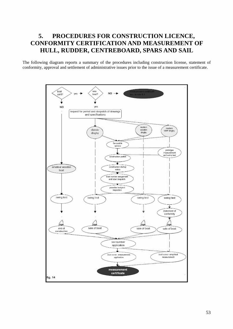
53
5. PROCEDURES FOR CONSTRUCTION LICENCE, CONFORMITY CERTIFICATION AND MEASUREMENT OF
HULL, RUDDER, CENTREBOARD, SPARS AND SAIL The following diagram reports a summary of the procedures including construction license, statement of conformity, approval and settlement of administrative issues prior to the issue of a measurement certificate.

54
5.1 Construction License Before constructing a 12’ Dinghy with any permitted material, the boatyard shall apply to the Class Authority by registered mail for a construction license. On that occasion, the boatyard shall deliver construction drawings and specifications of the boat it wishes to construct (see rule 1.8). This documentation will be reviewed by the Technical Committee who shall provide a grounded written opinion to the Class Authority. This opinion may be:
- favorable - favorable subject to alterations - unfavorable
The Class Authority shall transmit this opinion to the boatyard and, if favorable, attach the construction permit. - For classical or modern wooden boats, the boatyard having obtained a construction permit may start
construction subject to the prescriptions of rule 5.1.2. The approval procedure for modern wooden boats includes the execution of a swing test.
- For GRP boats, the boatyard having obtained a favorable opinion shall apply for the approval of the mould used to construct a prototype. The approval procedure includes the execution of a swing test. Following approval, the Class Authority will grant a construction license. The construction license will allow the boatyard to construct boats that are strictly compliant with the approved design/s and that are constructed using the approved moulds. Failure to comply with these rules may involve the withdrawal of construction license by the Class Authority.
5.1.1 Notification of hull construction start-up See rule 1.8. The boatyard shall notify the start-up of construction to the Class Authority, which shall assign a construction number to the boat different from the sail number.
5.1.2 Application for a construction number Having informed the Class Authority of the startup of construction, the boatyard shall apply for an identification number which the Class Authority shall carve in the construction plaque according to rule 1.9.
5.1.3 Builder inspections The boatyard shall permit the Class Authority to inspect the work at any time during its progress.
5.1.4 Statement of conformity Having completed a GRP boat and passed the swing test, the boatyard shall issue a statement of conformity where he shall declare that the boat is fully conforming with the AICD approved design and attach a copy of the prototype measurement report.
55
5.1.5 Amateur wooden construction Classical or modern wooden boats made by amateur builders do not need a license from the AICD Authority and are not subject to the obligation to notify construction startup.
5.1.6 Measurement Certificates
5.1.6.1 – Complete measurement If the boat is not provided with a statement of conformity, the owner shall ask a FIV licensed Measurer of his/her choice to execute a complete measurement of the boat. At the end of measurement, a detailed measurement report shall be drawn up. 5.1.6.2 – Partial measurement If the boat is provided with a statement of conformity, the owner shall ask a FIV licensed Measurer of his/her choice to execute a simplified measurement of the boat. At the end of measurement, a detailed measurement report shall be drawn up. 5.1.6.3 – Re-measurement for technical reasons If a measurement certificate is invalidated for technical irregularities or boat alterations which are denounced by the owner, a new measurement procedure shall be carried out. However, some prior measurements may be used, if the Measurer considers them as still valid. 5.1.6.4 – Re-measurement after maintenance If an approved boat needs repair for any reason, which involves the replacement of any element of the hull, the owner and builder shall use a material which has similar characteristics and quality and the same specific weight as the replaced material. To understand the type of maintenance that is carried out, 100% means the aggregate of the structural parts composing a classical Dinghy.
“Ordinary maintenance” is an operation to maintain efficiency and the original measurement status, including the replacement of non-structural elements. “Extraordinary maintenance” is an operation to recover efficiency and the original measurement status, including the replacement of no more than 20% of structural elements. “Renovation” is an operation to recover the original characteristics of the boat, including the replacement of no more than 50% of structural elements. “Reconstruction” is the replacement of more than 50% of structural elements.
The boats having undergone “renovation” or “reconstruction” shall be re-measured. In this case, any right stemming from a prior amnesty will decay. The purpose of maintenance is the recovery of the original construction conditions of the boat, including the replacement and/or repair of structural elements (such as timbers, strakes, etc.) in compliance with traditional constructing techniques. As included in this process, the use of epoxy or polyurethane glues is only permitted to eliminate residual waterways or repair rotten parts. Repairing the boat by simply coating and/or soaking its parts with resins is forbidden.
56
5.1.6.5 – Settlement of administrative issues Whenever a measurement certificate is invalidated for administrative reasons (e.g. change of ownership), a new one shall be issued, bearing the same number as the old certificate. No new boat measurement is needed. However, the Class Authority may request a new measurement at its discretion.
5.1.7 Forms All forms shall be handwritten. The available forms are shown in Annex A. The Class Authority can alter the forms whenever required.

57
6. VARIOUS TEMPORARY RULES
6.1 Coming into force of the New Rules
6.1.1 These Rules will come into force on the date of their approval by the Class in a general meeting, subject to any alteration requested by FIV pursuant to art. 57 of the bylaws. 6.1.2 The boats which on the effective date of these Rules are provided with a valid measurement certificate and are conforming to the Class Rules prevailing on the issue date of the measurement certificate, are allowed to race without alteration – subject to the prescriptions of rule 6.1.4. 6.1.3 The boats provided with a valid measurement certificate that were built before the approval of these Rules, whose hull shows original structural differences with respect to these Rules and/or the Rules in force on the issue date of the measurement certificate, are allowed to race without alteration – subject to the prescriptions of rule 6.1.4. 6.1.4 Fixed and running rigging and anything else that is not structural to the boat which is found non-conforming with these Rules shall be altered in 60 days from the coming into force of these Rules. 6.1.5 Failure to comply with these Rules will involve the rejection of the measurement certificate issue by the Class Authority or its invalidation on demand of a FIV measurer or of a Race Committee, subject to the prescriptions of rules 6.1.2. and 6.1.3.
6.2 Measurer refresher In the year following the coming into force of these Rules and prior to the general meeting date, the Technical Committee shall arrange a refresher course on new measuring procedures to be attended by FIV official measurers. Prior to that, the concerned official measurers may address to the Technical Committee for any measurement operating instruction.
6.3 Temporary Rule Interpretation Any doubt about the interpretation of these Rules shall be submitted to the Technical Committee, which will refer to the Management Committee and the Class Secretary. After that, the interpretation diffused by the Class Secretary will be binding to all members, up to the following general meeting whose agenda will include this interpretation.
58
7. RACING RULES
7.1 Documents In order to be admitted to race for the 12’ Dinghy class, the applicants shall be current members of AICD and FIV. This rule does not apply to foreign crews. Members shall have paid their class fees at least 15 days prior to racing application. In order to be admitted to the race, the applicants shall submit a Measurement Certificate issued by AICD and a FIV membership card. Foreign boats, which have no AIDC Measurement Certificate, shall declare to be current members and compliant with the measurement rules established by the respective National Authorities. It is the responsibility of the owner and helmsman to see that their boat conforms to the original measurements approved and, therefore, conforms to these Rules.
7.2 The Crew The crew is usually composed of one helmsman. Two people are admitted to every race, provided they have registered to the regatta. In any case, all regatta races shall be carried out by the registered crew.
7.3 Use of fittings while racing Oars may be replaced by a paddle. When sailing downwind, the paddle may be used to hold the boom in position. Its shape may be altered slightly (rounded centrally) in order to better fit the purpose. Toe straps are permitted.
7.4 Race equipment for “Classic Dinghies” Only Dinghies having a classical construction and equipped with wooden spars and a wooden rudder shall be admitted to Classical 12’ Dinghy regattas.
7.5 Mandatory safety equipment While racing, every boat shall be equipped with a floating rope measuring at least 8 meters in length and 8 mm in diameter, fixed to the mast below the mast bench. It may be kept inside a bag to be discernible from the running rigging. Equipment shall also include: one life jacket per person; one bailer or bucket (a large 5-litre bucket is mandatory for classical Dinghies or GRP Dinghies without a double bottom).
7.6 Permitted and forbidden optional equipment Permitted are: a compass, stopwatch, binocular, wind indicator, inclinometer, dogvane, non-electronic telltales of any type, signal and flag plates and one manual or electrical draining pump.

59
It is permitted to fit a cushion per side of max. 400 mm in length, to make racing more comfortable. It may be fixed with Velcro, both-sides adhesive tape or screws from the bottom of the fender to the bottom of the gunwale. However, it is forbidden to alter the original shape of the fender and gunwale in order to embed the cushion or increase its surface. Permitted are also: spare clothing, food and drinks, racing maps, instruments and spares for jury maintenance. A cellular phone for onboard safety (closed in a watertight bag) is permitted. It is forbidden to use electronic GPS means that may help to set the course, instantaneous speed indicators and any other equipment not specifically permitted.
7.7 Racing requirements The highest wind speed for 12’ Dinghy Class races is 8 m/s, and the highest wind speed at start cannot be lower than 2 m/s. In any case, races shall be finished in the maximum time specified in the advertisement of race. A race may be considered valid even if the course has been reduced. Subject to all the Race Committee’s rights in accordance with ISAF Racing Rules of Sailing. Italian Championships permit the use of no more than two mainsails and two gaffs, which shall be stamped prior to racing and made clearly identifiable. In all the other regattas, it is permitted to replace rigging between one race and another with new conforming elements and to set up approved sails.

60
Annex A - Forms (All forms shall be handwritten) A.1 – Statement of Conformity form

61
A.2 – Complete Measurement Form
Front

62
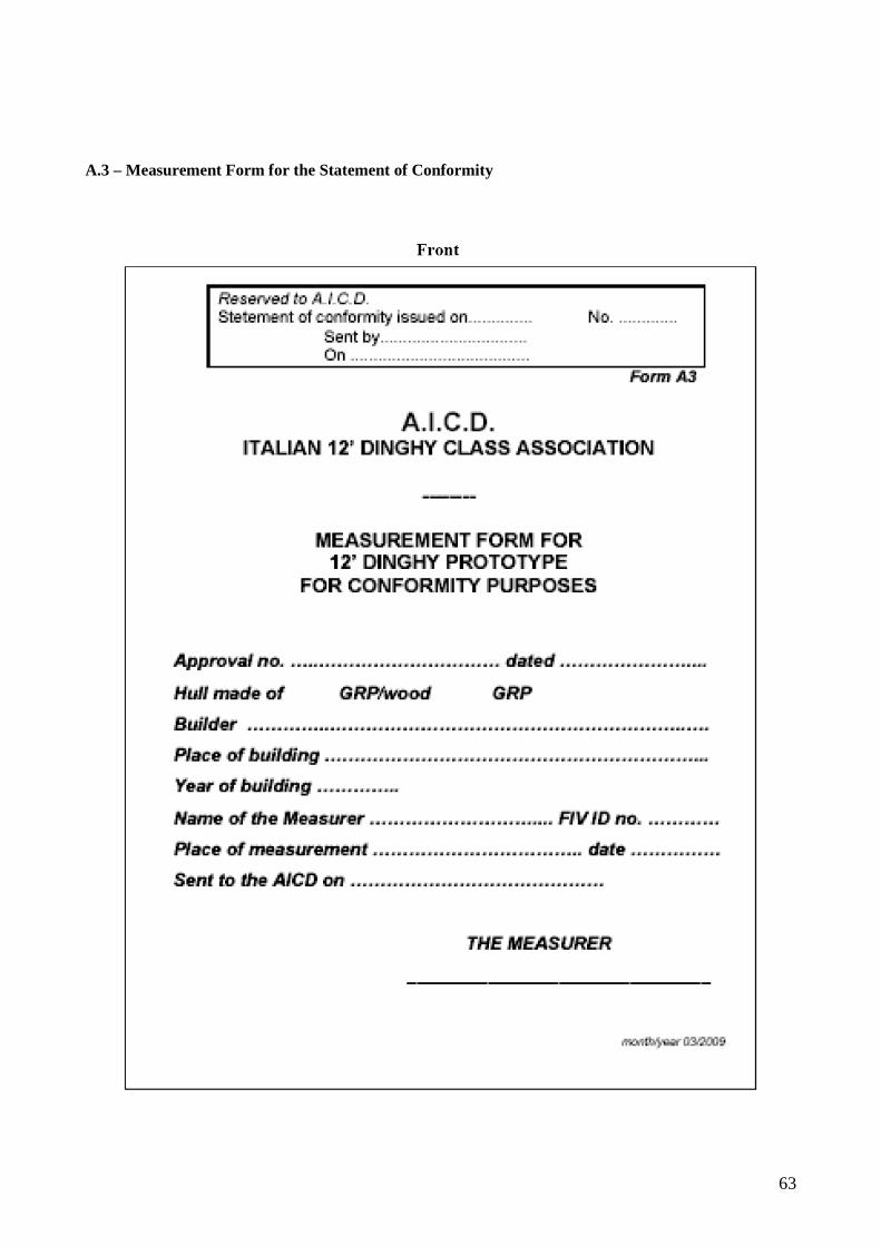
63
A.3 – Measurement Form for the Statement of Conformity
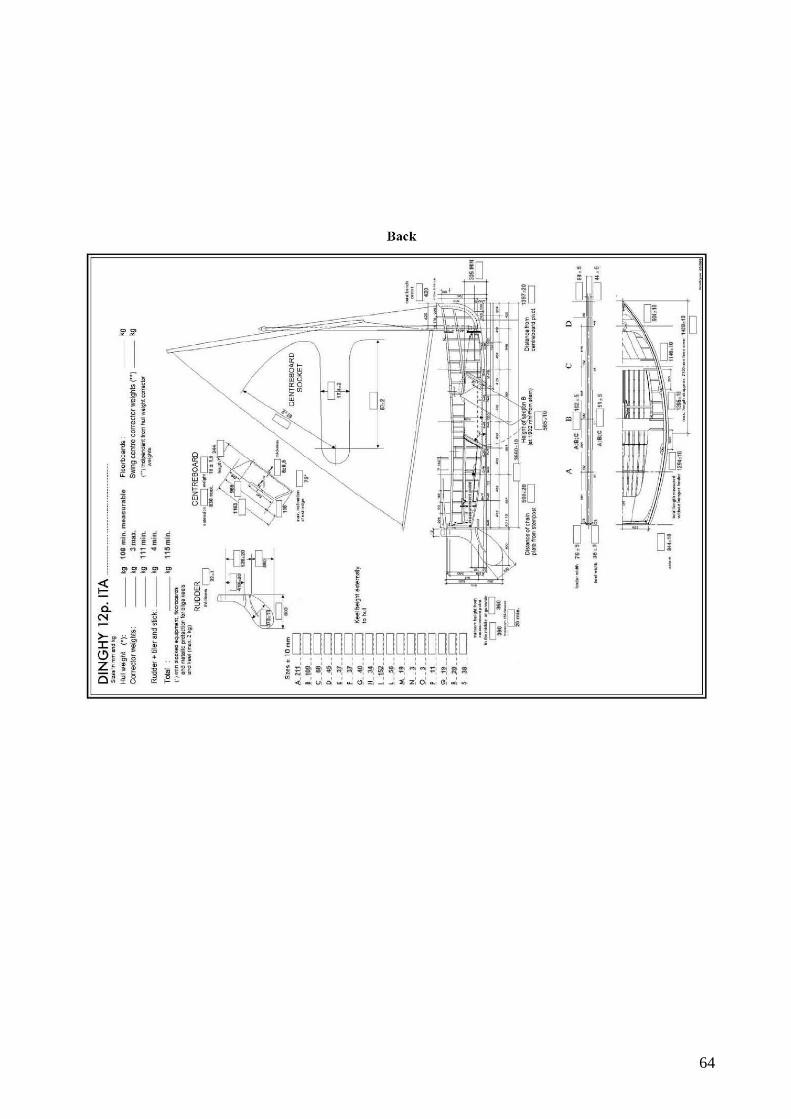
64

65
A.4 – Simplified Measurement Form for boats holding a Statement of Conformity

66

67
A.5 - Measurement Certificate

68

69
A.6 – Simplified Measurement Certificate
Front

70

71
A.7 – Back of Measurement Report/Certificate
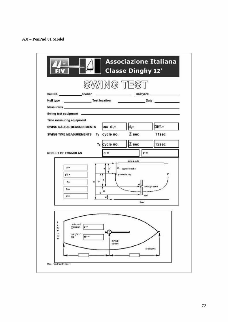
72
A.8 – PenPad 01 Model