clarus 600/650 d ms hardware guide - perkinelmer · significa que a instrução referida tem de ser...
TRANSCRIPT

Clarus 600/560 D MS Hardware Guide

Release History
Part Number Release Publication Date 09936768 C March 2008
Any comments about the documentation for this product should be addressed to: User Assistance PerkinElmer, Inc. 710 Bridgeport Avenue Shelton, Connecticut 06484-4794 U.S.A. Or emailed to: [email protected] Notices The information contained in this document is subject to change without notice. Except as specifically set forth in its terms and conditions of sale, PerkinElmer makes no warranty of any kind with regard to this document, including, but not limited to, the implied warranties of merchantability and fitness for a particular purpose. PerkinElmer shall not be liable for errors contained herein for incidental consequential damages in connection with furnishing, performance or use of this material. Copyright Information This document contains proprietary information that is protected by copyright. All rights are reserved. No part of this publication may be reproduced in any form whatsoever or translated into any language without the prior, written permission of PerkinElmer, Inc. Copyright © 2008 PerkinElmer, Inc. Produced in the US. Trademarks Registered names, trademarks, etc. used in this document, even when not specifically marked as such, are protected by law. PerkinElmer is a registered trademark of PerkinElmer, Inc. Clarus 600 is a trademark of PerkinElmer, Inc. Swagelok is a registered trademark of the Crawford Fitting Company. Teflon and Vespel are registered trademarks of E.I. duPont de Nemours and Company, Inc. Microsoft is a registered trademark of the Microsoft Corporation. Windows XP SP2 is a trademark of the Microsoft Corporation

Contents
3
Contents Warnings and Safety Information .................................................... 7 Conventions Used in this Manual................................................................... 9
Customer Service................................................................................... 12 Electromagnetic Compatibility (EMC)......................................................... 13
Regulatory Information ......................................................................... 13 Electrical Symbols Used on ClarusMS ................................................. 14 Label Location and Content .................................................................. 15
Clarus MS Safety Practices .......................................................................... 18 Generic Warnings.................................................................................. 18 Moving the Clarus MS .......................................................................... 19
Decontamination and Cleaning..................................................................... 21 Decontamination.................................................................................... 21 Cleaning the Instrument ........................................................................ 21 Compressed Gases................................................................................. 22 Ventilation ............................................................................................. 22 Heated Zones ......................................................................................... 23 Using Hydrogen, Methane or Isobutane................................................ 24 Using Ammonia Gas ............................................................................. 24 Hazardous Chemicals ............................................................................ 24 Definitions in Warnings for Hazardous Chemicals ............................... 26
Temperature, Humidity and Environment .................................................... 27 Operating Conditions............................................................................. 27 Storage Conditions ................................................................................ 28
General Laboratory Safety............................................................................ 29 WEEE Instructions for PerkinElmer Products.............................................. 30 Pre-Installation Requirements ...................................................................... 31
Laboratory Space Requirements............................................................ 31 Environmental Requirements ................................................................ 32 Power Requirements.............................................................................. 33 Safety Requirements.............................................................................. 35 Computer and System Software Requirements ..................................... 37 PC Requirements ................................................................................... 37 Operating System .................................................................................. 37 Software................................................................................................. 38 Instrument Firmware Versions .............................................................. 38
Clarus 600/560 D MS Hardware Guide
4
Printers................................................................................................... 38 Pre-Installation Checklist.............................................................................. 39 Introduction ...................................................................................... 41 Preface .......................................................................................................... 43
System Overview................................................................................... 43 Summary of this Guide.......................................................................... 44 Related Documentation ......................................................................... 44 About Part Numbers Listed in this Manual ........................................... 45
About the Clarus 600/560 D System ............................................... 47 About the Clarus 600/560 D System ............................................................ 49 Clarus 600/560 D GC ................................................................................... 51 GC Interface (Transfer Line) ........................................................................ 53 Reference Gas Inlet....................................................................................... 54 Ion Optics Path ............................................................................................. 57 Vacuum System............................................................................................ 59
Rotary Pump.......................................................................................... 59 Vacuum Pump Options.......................................................................... 61 Diffusion Pump Operating States .......................................................... 62 Diffusion Pump Operating States Continued ........................................ 63 Turbomolecular Pump ........................................................................... 64 Diffusion Pump ..................................................................................... 64 Vacuum Gauge ...................................................................................... 67
TurboMass Software..................................................................................... 68 Top Level Screen................................................................................... 68 Tune Page .............................................................................................. 69
Analytical Column........................................................................................ 70 Pre-Operational Checklist............................................................................. 71 Maintenance ...................................................................................... 73 Overview ...................................................................................................... 75 Typical Overall Maintenance Schedule........................................................ 77
Daily ...................................................................................................... 77 Weekly................................................................................................... 77 Monthly ................................................................................................. 78 Every Six Months .................................................................................. 78 Yearly .................................................................................................... 78

Contents
5
Leak Checking.............................................................................................. 79 Tuning Clarus 600/560 D MS....................................................................... 82 Preparing Clarus 600/560 D MS for Hardware Maintenance...................... 85 Changing a Column ...................................................................................... 88
Tools and Items Required...................................................................... 88 Removing a Column.............................................................................. 88 Connecting the New Column to the Split/Splitless Injector.................. 91 Connecting a New Column to Clarus 600 MS ...................................... 94
Refilling the Reference Gas Vial ................................................................ 100 Items Required .................................................................................... 100
Inner Source Maintenance .......................................................................... 104 Removing the Inner Source ................................................................. 105 EI Inner Source Maintenance .............................................................. 106 CI Inner Source Maintenance.............................................................. 113 Reinstalling the Source........................................................................ 119
Replacing a Filament .................................................................................. 121 Items and Tools Required.................................................................... 121
Replacing the Head Amplifier .................................................................... 126 Mass Analyzer Maintenance....................................................................... 128
Items and Tools Required.................................................................... 128 Cleaning Materials............................................................................... 129 Removing the Ion Optics Assembly.................................................... 129 Replacing an Outer Source Thermocouple.......................................... 139 Removing the Outer Source from the Ion Optics ................................ 141 Replacing Outer Source Heaters ......................................................... 142 Replacing the Quadrupole Heater........................................................ 144 Cleaning the Outer Source Lens.......................................................... 146 Reassembling the Ion Optics Assembly .............................................. 149 Reassembling the Clarus 600/560 D MS............................................. 152
Vacuum System Maintenance .................................................................... 154 Maintanenace of the Turbomolecular and Diffusion Pump ................ 154 Checking the Forepump Oil Level ...................................................... 154 Adding Oil to the Forepump Reservoir ............................................... 156 Decontaminating the Oil...................................................................... 156 Replacing the Oil................................................................................. 156
Inline Gas Purifiers ..................................................................................... 159 Changing from EI to CI Mode.................................................................... 160
Connecting the CI Gas......................................................................... 160

Clarus 600/560 D MS Hardware Guide
6
Changing to CI .................................................................................... 162 Leak Checking..................................................................................... 163 Setting-Up CI ...................................................................................... 165
Troubleshooting .............................................................................. 175 Overview .................................................................................................... 177
Spare Components............................................................................... 178 Logical Troubleshooting Steps............................................................ 178
Troubleshooting Chart ................................................................................ 180 Chromatography Related..................................................................... 191 Spectral Related................................................................................... 195 Communications Related..................................................................... 197 Forepump Related ............................................................................... 198
Message Dialogs......................................................................................... 201 Replacement Parts ...................................................................................... 207 Index ................................................................................................ 209

Warnings and Safety Information 1


Warnings and Safety Information
9
Conventions Used in this Manual
Normal text is used to provide information and instructions.
Bold text refers to text that is displayed on the touch screen.
All eight digit numbers are PerkinElmer part numbers unless stated otherwise.
Notes, warnings and cautions
Three terms, in the following standard formats, are also used to highlight special circumstances and warnings.
NOTE: A note indicates additional, significant information that is provided with some procedures.
Terminology
Throughout the manual, the term ‘mass spectrometer’ or MS specifically refers to the Clarus MS; while for ‘GC’ Clarus GC is implied.
CAUTION
Caution We use the term CAUTION to inform you about situations that could result in serious damage to the instrument or other equipment. Details about these circumstances are in a box like this one.

Clarus 600/560 D MS Hardware Guide
10
Caution (Achtung) Bedeutet, daß die genannte Anleitung genau befolgt werden muß, um einen Geräteschaden zu vermeiden.
Caution (Bemærk) Dette betyder, at den nævnte vejledning skal overholdes nøje for at undgå en beskadigelse af apparatet.
Caution (Advertencia) Utilizamos el término CAUTION (ADVERTENCIA) para advertir sobre situaciones que pueden provocar averías graves en este equipo o en otros. En recuadros éste se proporciona información sobre este tipo de circunstancias.
Caution (Attention) Nous utilisons le terme CAUTION (ATTENTION) pour signaler les situations susceptibles de provoquer de graves détériorations de l'instrument ou d'autre matériel. Les détails sur ces circonstances figurent dans un encadré semblable à celui-ci.
Caution (Attenzione) Con il termine CAUTION (ATTENZIONE) vengono segnalate situazioni che potrebbero arrecare gravi danni allo strumento o ad altra apparecchiatura. Troverete informazioni su tali circostanze in un riquadro come questo.
Caution (Opgelet) Betekent dat de genoemde handleiding nauwkeurig moet worden opgevolgd, om beschadiging van het instrument te voorkomen.
Caution (Atenção) Significa que a instrução referida tem de ser respeitada para evitar a danificação do aparelho.
WARNING
Warning We use the term WARNING to inform you about situations that could result in personal injury to yourself or other persons. Details about these circumstances are in a box like this one.
D
DK
E
F
I
NL
P

Warnings and Safety Information
11
Warning (Warnung) Bedeutet, daß es bei Nichtbeachten der genannten Anweisung zu einer Verletzung des Benutzers kommen kann
Warning (Advarsel) Betyder, at brugeren kan blive kvæstet, hvis anvisningen ikke overholdes. Warning (Peligro) Utilizamos el término WARNING (PELIGRO) para informarle sobre situaciones que pueden provocar daños personales a usted o a otras personas. En los recuadros como éste se proporciona información sobre este tipo de circunstancias.
Warning (Danger) Nous utilisons la formule WARNING (DANGER) pour avertir des situations pouvant occasionner des dommages corporels à l'utilisateur ou à d'autres personnes. Les détails sur ces circonstances sont données dans un encadré semblable à celui-ci.
Warning (Pericolo) Con il termine WARNING (PERICOLO) vengono segnalate situazioni che potrebbero provocare incidenti alle persone. Troverete informazioni su tali circostanze in un riquadro come questo.
Warning (Waarschuwing) Betekent dat, wanneer de genoemde aanwijzing niet in acht wordt genomen, dit kan leiden tot verwondingen van de gebruiker.
Warning (Aviso) Significa que a não observância da instrução referida poderá causar um ferimento ao usuário.
D
DK
E
F
I
NL
P

Clarus 600/560 D MS Hardware Guide
12
Customer Service This instrument is manufactured by:
PerkinElmer Inc. 710 Bridgeport Avenue Shelton, Connecticut 06484-4794 U.S.A.
Tel: 1 (800) 762-4000 Internet: http://www.perkinelmer.com
Warnings and Safety Information
13
Electromagnetic Compatibility (EMC)
Regulatory Information
United States (FCC) This equipment has been tested and found to comply with the limits for a Class A digital device, pursuant to part 15 of the FCC Rules. These limits are designed to provide reasonable protection against harmful interference when the equipment is operated in a commercial environment. This equipment generates, uses, and can radiate radio frequency energy and, if not installed and used in accordance with the instruction manual, may cause harmful interference to radio communications. Operation of this equipment in a residential area is likely to cause harmful interference in which user will be required to correct the interference at his own expense.
NOTE: Changes or modifications not expressly approved by PerkinElmer could cause the instrument to violate FCC (U.S. Federal Communications Commission) emission regulations, and because of this violation could void the user’s authority to operate this equipment.
Europe
All information concerning EMC standards is in the Declaration of Conformity, and these standards may change as the European Union adds new requirements.
CAUTION
The Clarus MS contains protective circuitry. Contact PerkinElmer Service before performing any AC line tests.

Clarus 600 GC-MS Hardware Guide
14
Electrical Symbols Used on ClarusMS
Alternating current.
Protective conductor terminal. Ground.
Off position of the main power switch.
On position of the main power switch.
Warning: Risk of electric shock.
Warning: Hot surface.
Caution, risk of danger Documentation must be consulted to determine the nature of the potential hazard and any actions which have to be taken.

Warnings and Safety Information
15
Label Location and Content
Clarus 600Mass Spectrometer
Figure 1 Front View of Clarus 600 MS Front View of Clarus 560 D
Clarus 600Mass Spectrometer

Clarus 600/560 D MS Hardware Guide
16
ROTARY PUMP
POWER IN
Air
PCEthernetConnection
Intakes
Processor ResetSwitch
AirExhaust
AirVents
Mass Spectrometer
Mass Spectrometer
GCInterface
120 VAC ~ 50/60Hz230 VAC ~ 50/60Hz
MAX POWER 1000 VAEN 55011-Class A, Group 1
CautionDo not restrict air intake or exhaust!
!Warning
120 VAC ~ 50/60Hz230 VAC ~ 50/60Hz
MAX POWER 1000 VAEN 55011-Class A, Group 1
This unit contains protective circuitry.Contact PerkinElmer qualified service personnel before performing any AC line tests
!Caution
S1
ETHERNET
Disconnect AC power cord from ouletbefore removing any cover or parts.Do not operate the instrument with anycover or parts removed.
Warning
Warning
This unit contains protective circuitry.Contact PerkinElmer qualified service personnel before performing any AC line tests.
Caution
Do not restrict air intake or exhaust.Caution
FCC ComplianceThis device complies with Part 15 of the FCC Rules.Operation is subject to the following two conditions:1) this device may not cause harmful interference, and2) this device must accept any interference received, including interference that may cause undesired operation.
Disconnect AC power cord from ouletbefore removing any cover or parts.Do not operate the instrument with anycover or parts removed.
Warning
WATERIN
WATEROUT
NVENT
2
NH
C HCI GAS
34
4 10
CH
15 psi(103 kPa)
MAX
5 psi(35 kPa)
MAX
50 psi(345 kPa)
MAX
Figure 2a Rear View of the Clarus 600 MS

Warnings and Safety Information
17
ROTARY PUMP
POWER IN
Air
PCEthernetConnection
Intakes
Processor ResetSwitch
AirExhaust
AirVents
PerkinElmer
Nxxxxxxx
Xxxxxxx
precisely.Shelton, CT 06484 USA
Part No.
Serial No.
Clarus 560 DMass Spectrometer
GCInterface
120 VAC ~ 50/60Hz230 VAC ~ 50/60Hz
MAX POWER 1000 VAEN 55011-Class A, Group 1
Caution!
!
!Caution
S1
FCC ComplianceThis device complies with Part 15 of the FCC Rules.Operation is subject to the following two conditions:1) this device may not cause harmful interference, and2) this device must accept any interference received, including interference that may cause undesired operation.
Disconnect AC power cord from ouletbefore removing any cover or parts.Do not operate the instrument with anycover or parts removed.
Warning
REMOVE VENT LINE BLANKING CAPAT INSTALLATION.
Warning
This unit contains protective circuitry.Contact PerkinElmer qualified service personnel before performing any AC line tests.
Caution
D o not restrict air in take o r exhaust.Caution
FCC Compliance
Warning
2On/Off Switch
Figure 2b Rear View of the Clarus 560 D MS

Clarus 600/560 D MS Hardware Guide
18
Clarus MS Safety Practices
NOTE: This equipment requires no specified inspection or preventive maintenance to ensure the continuous functioning of its safety features.
The Mass Spectrometer should be used in accordance with the instructions provided in the user’s manuals and tutorial supplied with the instrument. If used otherwise, the protection provided by the instrument may be impaired.
WARNING
Do not attempt to make adjustments, replacements or repairs to this instrument except as described in the accompanying user documentation.
WARNING
Explosive Atmosphere. This instrument is not designed for operation in an explosive atmosphere.
Generic Warnings Before installing or operating the MS, read the following topics concerning hazards and potential hazards. Ensure that anyone involved with installation and/or operation of the MS is knowledgeable in both general safety practices for the laboratory and safety practices for this instrument. Get advice from your safety engineer, industrial hygienist, environmental engineer, or safety manager before you install or use this instrument.
This equipment requires no specified inspection or preventive maintenance to ensure the continuous functioning of its safety features.

Warnings and Safety Information
19
Moving the Clarus MS
WARNING
Depending on the Clarus 600 MS GC pump option selected, the instrument weight will range from 46.8 kg (102 lb) to 49.9 kg (110 lb).
The Clarus 560 D MS is 48 kg (105 lb) in weight.
The mass spectrometer requires two people to safely lift it and should be lifted from the bottom. Use the following lifting posture to avoid back injury: With knees bent, simultaneously lift the instrument out of the carton as you end up in a standing position.
WARNING
Connect the mass spectrometer to an AC line power outlet that has a protective ground connection. To ensure satisfactory and safe operation of the mass spectrometer, it is essential that the protective ground conductor (the green/yellow lead) of the line power cord is connected to a true electrical ground. Any interruption of the protective ground conductor, inside or outside the mass spectrometer, or disconnection of the protective ground terminal may impair the protection provided by the mass spectrometer.
WARNING
Never operate the mass spectrometer with any covers or parts removed.
WARNING
Do not make adjustments, replacements or repairs to the mass spectrometer except as described in this manual. Only a PerkinElmer Service Representative or similarly trained and authorized person should be permitted to service the mass spectrometer.
Ensure that the power cord is correctly wired and that the ground leads of all electrical units (for example, recorders, integrators) are connected together via the
Clarus 600/560 D MS Hardware Guide
20
circuit ground to earth. Use only three-prong outlets with common earth ground connections.
• Servicing of electrical components within the mass spectrometer should be performed only by a PerkinElmer Service Representative or similarly trained and authorized person.
• Servicing of the incoming AC power line components in your laboratory should be performed only by a licensed electrician.
WARNING
Electrical shock hazard. To prevent electrical shock, disconnect the power cord from the AC outlet before servicing.
WARNING
Disconnect AC power cord from outlet before removing any cover or parts. Do not operate the instrument with any covers or parts removed.
Under no circumstances should circuit boards be removed or inserted unless the instrument is disconnected from line power.

Warnings and Safety Information
21
Decontamination and Cleaning
Before using any cleaning or decontamination methods except those specified by PerkinElmer, users should check with PerkinElmer that the proposed method will not damage the equipment.
Decontamination Customers wishing to return instrumentation and/or associated materials to PerkinElmer for repair, maintenance, warranty or trade-in purposes are advised that all returned goods must be certified as clean and free from contamination. The customer’s responsible body is required to follow the "Equipment Decontamination Procedure" and complete the “Certificate of Decontamination”. These documents are available on the PerkinElmer public website:
http://las.perkinelmer.com/OneSource/decontamination.htm
If you do not have access to the internet and are located in the U.S., call toll free at 1-800-762-4000 or (+1) 203-925-4602, 8:30 a.m. – 7 p.m. EST and speak to Customer Support.
In Canada, call toll free 800-561-4646 and speak to Customer Support.
If you are located outside of the United States or Canada, please call your local PerkinElmer sales office for more information.
Cleaning the Instrument
Exterior surfaces may be cleaned with a soft cloth, dampened with a mild detergent and water solution. Do not use abrasive cleaners or solvents.

Clarus 600/560 D MS Hardware Guide
22
Compressed Gases
WARNING
Compressed Gases. High pressure gas cylinders can be dangerous if mishandled or misused. Always handle gas cylinders with caution and observe your local regulations for the safe handling of gas cylinders.
Avoid banging the valves, and ensure that the correct valves and gauges are installed. It is recommended that gas cylinders be stored and placed outside the laboratory and connected to the instrument through specially cleaned copper tubing. Take care not to kink or stress the gas tubing. For safety, cylinders must be firmly clamped in an upright position.
WARNING
Explosive hazard. When using hydrogen, methane or isobutane, special care must be taken to avoid buildup of explosive gas mixtures either in the GC oven or the mass spectrometer vacuum manifold.
Ensure that all hydrogen line couplings are leak-free and do not allow hydrogen to vent within the oven.
Ventilation
WARNING
Hazardous vapors. When analyzing hazardous compounds, such as pesticides, or running in the chemical ionization (CI) mode, it is necessary to vent the mass spectrometer effluent from the forepump exhaust into a fume hood or charcoal trap.
Warnings and Safety Information
23
WARNING
Toxic Gases-Fume Ventilation System. Without adequate ventilation potentially toxic vapors can build up in the laboratory. Your laboratory must have reliable fume ventilation system before you use this instrument.
Adequate ventilation must be provided, particularly if a liquid nitrogen or carbon dioxide subambient accessory is in constant use. The area underneath the bench (around the forepump) should be well ventilated. An oil separation filter and charcoal trap should be installed at the outlet of the forepump exhaust to prevent contamination if fume hood venting is unavailable.
To ensure adequate cooling of the instrument electronics, do not obstruct the gap at the base of the Clarus MS/Clarus GC, and if practical, leave a minimum 6 inch clearance between each instrument in the system (for example, the ATD or HS 40XL). This does not include the Clarus MS/Clarus 600 GC as they are connected together.
Heated Zones
WARNING
Risk of burns. Never touch a heated mass spectrometer transfer line or a GC injector cap with unprotected (bare) fingers.
Heated zones should be treated with caution, for example, the transfer line, injector caps, and detectors. In addition, the detector cover may get hot, especially if flame ionization detectors are operated at high temperatures. As a general rule, allow heated zones to cool before attempting to work in the GC oven, on the transfer line, on an injector, around the detector areas or inside the mass spectrometer manifold. Cooling of the transfer line may require a wait of ½ to 1 hour.

Clarus 600/560 D MS Hardware Guide
24
Using Hydrogen, Methane or Isobutane
WARNING
Explosive Hazard. If the hydrogen is turned on without a column attached to the injector and/or detector fittings inside the oven, the gas could diffuse into the oven creating the possibility of an explosion.
If the mass spectrometer is not under vacuum, hydrogen, methane, or isobutane can fill the vacuum chamber thereby creating an explosive hazard.
To avoid possible injury, do not turn on the hydrogen unless a column is attached, all joints have been leak-tested, and the mass spectrometer is under vacuum with the forepump exhaust properly vented to a fume hood.
Using Ammonia Gas
WARNING
Hazardous gas vapors. When using ammonia gas while running in the chemical ionization (CI) mode, it is necessary to vent the mass spectrometer effluent from the forepump exhaust into a fume hood or outside the building.
Hazardous Chemicals
WARNING
Hazardous chemicals. Before using samples, thoroughly familiarize yourself with all hazards and safe handling practices. Observe the manufacturer’s recommendations for use, storage and disposal. These recommendations are normally provided in the Material Safety Data Sheets (MSDS) supplied with the solvents, chemicals, and pump oils.
Be aware that the chemicals that you use in conjunction with the mass spectrometer may be hazardous. Do not store, handle, or work with any chemicals or hazardous
Warnings and Safety Information
25
materials unless you have received appropriate safety training and have read and understood all related Material Safety Data Sheets (MSDS). MSDSs give information on physical characteristics, precautions, first aid, spill clean up and disposal procedures. Familiarize yourself with the information and precautions contained in these documents before attempting to store, use or dispose of the reagents. Comply with all federal, state, and local laws related to chemical storage, handling and disposal.
You must work under a suitable hood when handling and mixing certain chemicals. The room in which you work must have proper ventilation and a waste collection system. Always wear appropriate safety attire (full-length laboratory coat, protective glasses, gloves etc.) as indicated on Material Safety Data Sheets.
WARNING
When using toxic samples, the mechanical pump oil is toxic waste.
WARNING
Some chemicals used with the mass spectrometer may be hazardous or may become hazardous after completion of an analysis. The responsible person (for example, the Lab Manager) must take the necessary precautions to ensure that operators and people in the surrounding workplace are not exposed to hazardous levels of toxic substances (chemical or biological) as defined in the applicable Material Safety Data Sheets (MSDS) or OSHA, ACGIH, or COSHH documents. Venting for fumes and disposal of waste must be in accordance with all national, state and local health and safety regulations and laws.

Clarus 600/560 D MS Hardware Guide
26
Definitions in Warnings for Hazardous Chemicals
Responsible body: Individual or group responsible for the use and maintenance of equipment, and for ensuring that operators are adequately trained. [per EN/IEC 61010-1].
Operator: Person operating equipment for its intended purpose. [per EN/IEC 61010-1].
OSHA: Occupational Safety and Health Administration (United States).
ACGIH: American Conference of Governmental Industrial Hygienists.
COSHH: Control of Substances Hazardous to Health (United Kingdom).
Warnings and Safety Information
27
Temperature, Humidity and Environment
Operating Conditions
CAUTION
The Clarus MS is designed for indoor use only in a laboratory environment that is clean and is free of drafts, direct sunlight and vibration.
CAUTION
Do not operate the mass spectrometer in a Cold Room or a refrigerated area. Clarus MS operates under the following conditions:
Ambient temperature is 10 °C to 35 °C (50 °F and 95 °F) with a variability of less than ± 4 °C (± 7 °F).
The Clarus MS will operate safely between 5°C and 40 °C (41 °F and 104 °F).
If operating at ambient temperatures between 30°C and 35 °C, you will need the water-cooling option for the turbopump.
Ambient relative humidity is 20 % to 80 % non-condensing.
Operating altitude is in the range of 0 to 2000 m.
WARNING
The mass spectrometer is not designed for operation in an explosive environment. The laboratory should be free of flammable, explosive, toxic, caustic, or corrosive vapors or gases and should be relatively free of dust.
Pollution Degree: Clarus MS will operate safely in environments that contain non-conductive foreign matter up to Pollution Degree 2 in EN/IEC 61010-1.

Clarus 600/560 D MS Hardware Guide
28
Storage Conditions
The mass spectrometer may be stored under the following conditions:
• Ambient temperature is -20 °C to +60 °C (-4 to 140 °F).
• Ambient relative humidity is 20 to 80 %, non-condensing.
• Altitude is in the range 0 to 12000 m.
• The instrument is stored in an upright position.

Warnings and Safety Information
29
General Laboratory Safety
Your laboratory should have all equipment ordinarily required for the safety of individuals working with chemicals (fire extinguishers, first-aid equipment, safety shower and eye-wash fountain, spill cleanup equipment, etc.).

Clarus 600/560 D MS Hardware Guide
30
WEEE Instructions for PerkinElmer Products
or
A label with a crossed-out wheeled bin symbol and a rectangular bar indicates that the product is covered by the Waste Electrical and Electronic Equipment (WEEE) Directive and is not to be disposed of as unsorted municipal waste. Any products marked with this symbol must be collected separately, according to the regulatory guidelines in your area.
The objectives of this program are to preserve, protect and improve the quality of the environment, protect human health, and utilize natural resources prudently and rationally. Specific treatment of WEEE is indispensable in order to avoid the dispersion of pollutants into the recycled material or waste stream. Such treatment is the most effective means of protecting the customer’s environment.
Requirements for waste collection, reuse, recycling, and recovery programs vary by regulatory authority at your location. Contact your local responsible body (e.g., your laboratory manager) or authorized representative for information regarding applicable disposal regulations. Contact PerkinElmer at the web site listed below for information specific to PerkinElmer products.
Web address:
http://las.perkinelmer.com/OneSource/Environmental-directives.htm
For Customer Care telephone numbers select “Contact us” on the web page.
Products from other manufacturers may also form a part of your PerkinElmer system. These other producers are directly responsible for the collection and processing of their own waste products under the terms of the WEEE Directive. Please contact these producers directly before discarding any of their products. Consult the PerkinElmer web site (above) for producer names and web addresses.
Warnings and Safety Information
31
Pre-Installation Requirements
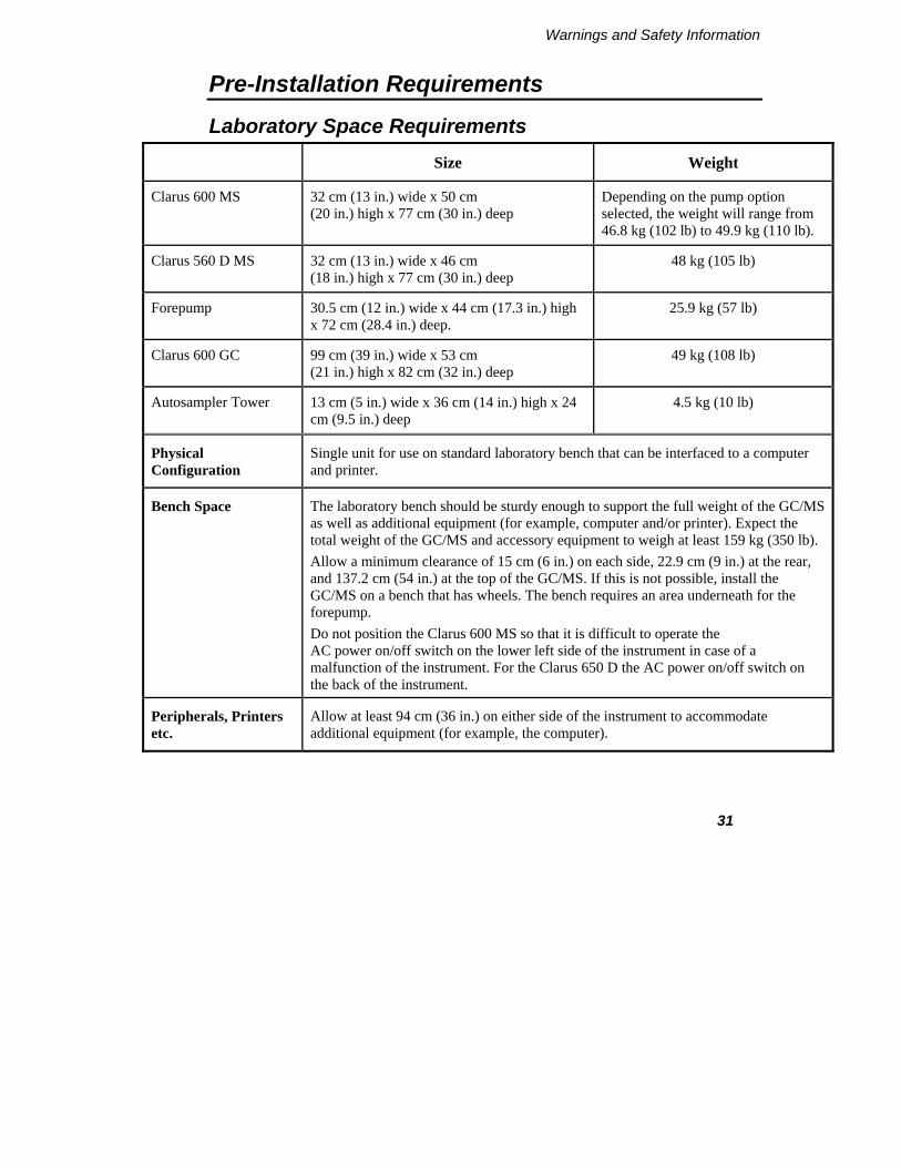
Laboratory Space Requirements Size Weight
Clarus 600 MS 32 cm (13 in.) wide x 50 cm (20 in.) high x 77 cm (30 in.) deep
Depending on the pump option selected, the weight will range from 46.8 kg (102 lb) to 49.9 kg (110 lb).
Clarus 560 D MS 32 cm (13 in.) wide x 46 cm (18 in.) high x 77 cm (30 in.) deep
48 kg (105 lb)
Forepump 30.5 cm (12 in.) wide x 44 cm (17.3 in.) high x 72 cm (28.4 in.) deep.
25.9 kg (57 lb)
Clarus 600 GC 99 cm (39 in.) wide x 53 cm (21 in.) high x 82 cm (32 in.) deep
49 kg (108 lb)
Autosampler Tower 13 cm (5 in.) wide x 36 cm (14 in.) high x 24 cm (9.5 in.) deep
4.5 kg (10 lb)
Physical Configuration
Single unit for use on standard laboratory bench that can be interfaced to a computer and printer.
Bench Space The laboratory bench should be sturdy enough to support the full weight of the GC/MS as well as additional equipment (for example, computer and/or printer). Expect the total weight of the GC/MS and accessory equipment to weigh at least 159 kg (350 lb). Allow a minimum clearance of 15 cm (6 in.) on each side, 22.9 cm (9 in.) at the rear, and 137.2 cm (54 in.) at the top of the GC/MS. If this is not possible, install the GC/MS on a bench that has wheels. The bench requires an area underneath for the forepump. Do not position the Clarus 600 MS so that it is difficult to operate the AC power on/off switch on the lower left side of the instrument in case of a malfunction of the instrument. For the Clarus 650 D the AC power on/off switch on the back of the instrument.
Peripherals, Printers etc.
Allow at least 94 cm (36 in.) on either side of the instrument to accommodate additional equipment (for example, the computer).

Warnings and Safety Information
32
Environmental Requirements
Pollution Degree This instrument will operate safely in environments that contain non-conductive foreign matter up to Pollution Degree 2 as defined in EN/IEC 61010-1.
Laboratory Environment
Install the GC/MS in an indoor laboratory environment that is clean and free of drafts and direct sunlight.
The laboratory should be free of flammable, explosive, toxic, caustic or corrosive vapors or gases, and should be relatively free of dust.
The ambient laboratory temperature should be between 10 °C and 30 °C (50 °F and 86 °F) for Clarus 600 C, 600 T, and 600 S systems unless the turbomolecular pump is water cooled, and between 10 °C and 35 °C (50 °F and 95 °F) for Clarus 600 D, or for Clarus 600 C, 600 T, and 600 S systems with water cooling.

Clarus 600 GC-MS User’s Guide
33
Power Requirements
Clarus MS All electrical supplies must be smooth, clean, and free of line transients greater than 40 V peak to peak, and must meet and remain within the following tolerances:
120 VAC ±10 % @ 50/60 Hz ±1 % 1000 VA maximum 230 VAC ±10 % @ 50/60 Hz ±1 % 1000 VA maximum
Add 100 VA for the computer and 108 VA for a printer.
Clarus GC All electrical supplies must be smooth, clean, and free of line transients greater than 40 V peak to peak, and must meet and remain within the following tolerances: For GC with slow heating rate as standard; 120 VAC ± 10% @ 50/60 Hz ± 1% @ 20 Amps, 2400 VA maximum 230 VAC ± 10% @ 50/60 Hz ± 1% @ 10 Amps, 2400 VA maximum
For GC with optional oven heater for fast heating rate; 220 VAC ± 5% @ 50/60 Hz ± 1% @ 15 Amps, 3120 VA maximum 230 VAC ± 5% @ 50/60 Hz ± 1% @ 16 Amps, 3120 VA maximum 240 VAC ± 5% @ 50/60 Hz ± 1% @ 13 or 16 Amps, 3120 VA max
Instruments and peripherals must not be connected to circuits with large inductive or large and frequent loads (for example, large motors, discharge lamps, photocopy systems, radio transmitters, etc.).
Clarus 600/560 D MS Hardware Guide
34
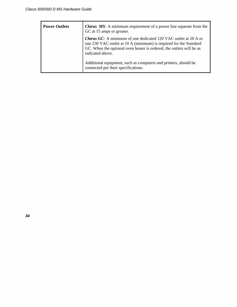
Power Outlets Clarus MS: A minimum requirement of a power line separate from the GC at 15 amps or greater.
Clarus GC: A minimum of one dedicated 120 VAC outlet at 20 A or one 230 VAC outlet at 10 A (minimum) is required for the Standard GC. When the optional oven heater is ordered, the outlets will be as indicated above.
Additional equipment, such as computers and printers, should be connected per their specifications.

Warnings and Safety Information
35
Safety Requirements
Gas Delivery Lines
Copper tubing that is free of grease, oil and organic material must always be used with the Clarus 600 MS on all gas lines, except ammonia reagent gas. Ammonia reagent gas requires stainless steel.
Solvent-washed copper tubing must be used to avoid contamination of the Gas Chromatograph. Suitable solvents are acetone or dichloromethane (do not use if negative chemical ionization is planned) followed by methanol. Clean helium or nitrogen should be used to blow any residual solvent from the tubing. Cap all unused tubing.
Care must be taken not to kink or overstress the gas delivery lines. Strain relief consisting of two one inch coils of tubing should be installed at every gas line connection.
Gas Cylinders All gas cylinders should be firmly clamped to a suitable surface.
Gas cylinders should be located outside of the laboratory whenever possible, and should always be stored and operated in a vertical position.
Hydrogen Ensure that all hydrogen lines and connections are leak-free. When using a hydrogen tank, install an in-line hydrogen snubber (part number 00090038) between the tank regulator and the delivery tubing.
Ventilation Always provide adequate ventilation. When analyzing hazardous compounds such as pesticides, it may be necessary to arrange to vent the mass spectrometer effluent from the forepump into a fume hood. To prevent contamination if a fume hood is unavailable, an oil separation filter should be installed at the outlet of the forepump vented to a fume hood or an oil mist separator (Alcatel 68316) with a charcoal trap (Koby KA1). An acceptable alternative is to attach a ½ inch Tygon tube and vent to a hood. Pump oil vapor is considered toxic and must be vented properly.

Clarus 600/560 D MS Hardware Guide
36
Gas Requirements
Carrier gases used with the mass spectrometer require a minimum purity of 99.999%. Gas cylinders should be located outside of the laboratory whenever possible, and should always be stored and operated in the vertical position.
CAUTION For all gases delivered to the mass spectrometer, always use copper tubing that is free of grease, oil, and organic material. If in doubt about the condition of your tubing, clean it before use.
Gases
GC/MS Carrier Gases:
Helium
Minimum purity of 99.999% for helium or hydrogen. Carrier gas tubing should be ultra-clean.
A number 1A (200 ft3) gas cylinder should be used for all carrier gases with a high-purity, stainless-steel diaphragm, two-stage regulator. Filter through a moisture filter and/or hydrocarbon trap and de-oxo filter designed for MS.
Gas delivery pressure to the GC should be 70 – 100 psi (483 – 689 kPa). Do not exceed 100 psi (689 kPa) on the carrier gas inlet.
Reagent Gases:
Ammonia
Methane and Isobutane
Minimum purity of 99.999% for methane, minimum purity of 99.98% for isobutane, minimum purity of 99.998% for ammonia. Carrier gas tubing should be ultra-clean.
The gas delivery pressure required is 15 psi (103 kPa) to the bulkhead fitting (1/8 in. Swagelok) on the mass spectrometer.
If ammonia is used for chemical ionization, all fittings and tubing must be stainless steel to avoid corrosion. A single-stage regulator is required for ammonia, rated for corrosive service. Also, the forepump must be vented to a fume hood or outside the building.
A high-purity, stainless-steel diaphragm, two-stage regulator is required for methane and isobutane with a final delivery pressure of 15 psi (103 kPa). Clean tubing must be used. It must be solvent-washed and nitrogen-dried. The bulkhead connector at the rear of the instrument is a 1/8 in. Swagelok fitting.
The use of commercial gas purifiers for reagent gas is recommended.

Warnings and Safety Information
37
Computer and System Software Requirements
To ensure that your system performs at the expected high level, your computer must be configured to the minimum capabilities indicated below.
These requirements may be updated as the requirements for TurboMass software and/or Microsoft Windows XP SP2 are changed. Consult the latest Product Description List for current requirements.
NOTE: This guide does not cover the installation and configuration of your computer. If you have purchased a complete system from PerkinElmer, the computer will be configured by your Service Engineer during product installation.
PC Requirements
The TurboMass software is installed at PerkinElmer prior to shipment and tested using the following minimum PC system specifications. If you need to reinstall the software, verify that the PC meets the following minimum requirements:
• Dell OptiPlex 745, GX620, GC270, or GX 280
• Intel® Pentium processor
• 512 MB of Random Access Memory (RAM)
• High Color (16 bit) at 1024 x 768 SVGA
• Hard disk with 2.0 GB free space
• 8x speed CD-ROM drive
• 1 RS-232 port
• 2 RJ-45 10/100Base-T ports
• A keyboard and PS/2®-style mouse
Operating System Windows XP SP2

Clarus 600/560 D MS Hardware Guide
38
Software TurboMass Software.
Instrument Firmware Versions Internal dotLINK
Printers • HP LaserJet 4200 Printer Series (HP 4200, 4210, and 4250)
• HP DeskJet 5650 Color InkJet Printer NOTE: Using any printers other than the ones recommended above may not correctly
display the Communiqué reports.
.

Warnings and Safety Information
39
Pre-Installation Checklist
MODEL: __________________________ DATE: _____________________
CUSTOMER: __________________________________
SPO#: __________________________________
Requirements OK Needs Prior To Installation
Customer Responsibility
Lab Space Requirements
Power Requirements
Gas Requirements
Environmental Requirements
Safety Requirements
Preparation of Samples (Customer Responsibility)
Computer Configuration
Customer Experience

Clarus 600/560 D MS Hardware Guide
40

Introduction 2


Introduction
43
Preface
The Clarus MS is a benchtop mass spectrometer designed with the user in mind. The small profile of combination Gas Chromatograph and Mass Spectrometer (GC/MS) allows it to fit on a standard six foot long laboratory bench. Sophisticated software controls the GC/MS from a Windows XP SP2 computer.
System Overview
The system consists of:
• Clarus GC.
• Clarus MS.
• Computer.
• TurboMass Software.
• Foreline Pump.

Introduction
44
Summary of this Guide
Thoroughly read and understand the Safety and Regulatory Information chapter before using the mass spectrometer.
Chapter 1: Warnings and Safety Information
Contains all of the safety information and topics to comply with EN/IEC 61010.
Chapter 2: Introduction
Provides an instrument overview and the references to related documentation.
Chapter 3: About the Clarus 600/560 D System
Describes each of the components in the system and includes a list of items to check before using the instrument.
Chapter 4: Maintenance
Contains preventive and routine maintenance procedures that typical users can perform.
Chapter 5: Troubleshooting
Provides helpful troubleshooting tips and a table to help you identify and solve typical problems.
Related Documentation The Clarus 600/560 D family of manuals includes the following:
• Clarus 600/560 D MS Tutorial (part number 09936769): The tutorial provides a step-by-step guide to performing a number of tasks using the instruments and software.

Warnings and Safety Information
45
• Software User’s Guide (part number 09936767): A comprehensive manual describing the functionality of each part of the TurboMass software. It describes the keys and fields on each screen.
• Clarus 600/560 D MS Hardware Manual (part number 09936768): Contains the required safety and regulatory information required for EN/IEC 61010. It contains an overview of mass spectrometry and of each component in this system; a pre-operational checklist, typical user maintenance and a troubleshooting guide.
• Service Manual (not included): Contains information for trained service engineers to completely service the Clarus.
About Part Numbers Listed in this Manual
The part numbers listed in this manual are available from PerkinElmer’s catalog service.
Supplies, Accessories and Replacement Parts
Supplies, accessories, and replacement parts can be ordered directly from PerkinElmer's catalog service. PerkinElmer offers a full selection of high-quality chromatography data handling products and gas chromatography supplies and columns through e-essentials.
To place an order for supplies and many replacement parts, request a free e-essentials catalog, or ask for information:
Telephone:
• U.S. only: Call toll free 1-800-762-4000, 8:30 a.m. to 7 p.m. EST. Your order will be shipped promptly, usually within 24 hours.
• Worldwide: Call your local PerkinElmer sales or service office or call PerkinElmer, Shelton, CT USA
Internet: http://www.perkinelmer.com

Clarus 600 MS User’s Guide
46

About the Clarus 600/560 D System 3


About the Clarus 500 System
49
About the Clarus 600/560 D System
The Clarus 600/560 D mass spectrometer is a compact benchtop instrument that produces positive identification and quantitation of compounds separated by the Clarus 600/560 D GC. Even if the compounds coelute, the mass spectrometer can still positively identify and quantitate each compound. Clarus 600 MS is designed to run analyses that best identify your sample by using the electron impact (EI) or chemical ionization (CI) mode. The Clarus 560 D MS runs analyses that identify your sample by using the electron impact (EI) mode.
The Clarus 600/560 D system is controlled by a PC using TurboMass Software. The application runs in a Microsoft Windows XP SP2 operating environment. The software user interface contains color graphics and provides full user interaction with either the keyboard or the mouse. TurboMass completely controls the GC/MS system from tuning and data acquisition (scanning or selected ion recording mode), through quantifying your results. Complete operating instructions of all TurboMass controls are in the TurboMass Software Guide (part number 0993-6767), supplied with the system.
A high-performance, research-grade analytical quadrupole mass analyzer with a quadrupole prefilter assembly transmits only those ions having your selected mass-to-charge ratio. The prefilter rod set improves sensitivity and protects the analytical quadrupole rods from contaminating ion deposits. Ions emerging from the quadrupole mass analyzer are converted to photons and detected by the photomultiplier detector system. The low noise photomultiplier typically operates with a gain of 105.

Clarus 600 MS Hardware Guide
50
Figure 3 Clarus MS with Clarus GC
The system consists of two major components: Clarus MS and the Clarus GC. Brief descriptions of each major component follow.

About the Clarus 600/560 D System
51
Clarus 600/560 D GC
The Clarus 600/560 D Gas Chromatograph is a dual-channel, temperature-programmable gas chromatograph (GC). It is available in many configurations, such as with or without, an autosampler, programmable pneumatic control (PPC), and a variety of injector/detector combinations to provide you with total GC flexibility. The Clarus 600/560 D GC is microprocessor controlled, where you enter the operating parameters and view the prompting text and monitor instrument functions on a large full-color touch screen display.
Figure 4 Clarus 600/560 D GC
The Programmed Pneumatic Control (PPC) Version of the Clarus 600/560 D GC is used where the carrier gas and detector gases are monitored and controlled by the microprocessor, thereby producing a fully automated system that is capable of managing all pneumatic functions within the gas chromatograph.

Clarus 600 MS Hardware Guide
52
The Clarus 600/560 D GC can store up to five GC methods. Methods can be generated, copied, deleted, edited, set up, and printed. These methods are normally developed and stored on the TurboMass data system. The automatic liquid autosampler can run up to 15 injections per vial from as many as 82 vials and one priority vial using one or two autosampler programs (if not under TurboMass control). In the latter case, a different GC method can be used by each program if desired.
PPC provides real-time digital readouts to simplify setting carrier gas pressures and flows.
Figure 5 Clarus 600 Mass Spectrometer

About the Clarus 600/560 D System
53
GC Interface (Transfer Line)
The detector end of a capillary GC column in the Clarus 600/560 D GC oven is inserted through a temperature-controlled transfer line and optimally positioned so that the column end is flush with the inner wall of the EI or CI ion source. The transfer line is temperature controlled by Clarus MS and has a 350 °C upper limit. If the Clarus 600 GC detects improper operation (for example, no carrier gas) and goes into an alarm condition, it will turn off the temperature to the transfer line.
CAUTION Do not use metal capillary columns in the transfer line. They may electrically short-out the source.
Figure 6 The transfer line
Clarus 600 MS Hardware Guide
54
Reference Gas Inlet
The reference gas inlet system consists of a glass bulb filled with heptacosa (FC43) connected to tubing which directs it to the ion source. You can switch the reference gas solenoid valve on and off and also purge the reference gas lines from the Tune screen.
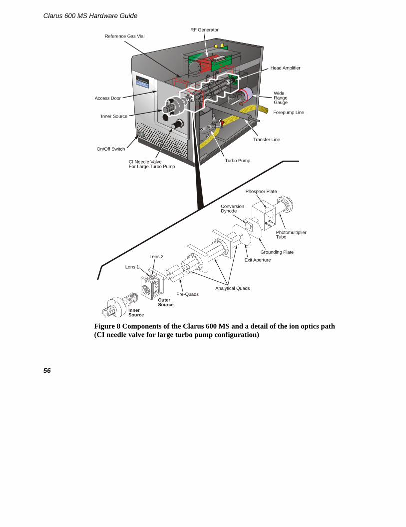
Figure 7 and 8 shows the components or assemblies that comprise the Clarus 600/560 D MS with the manual vent switch (Clarus 600 D and Clarus 560 D) or the CI adjustment valve (Clarus 600 C) configuration (see the following two pages).

About the Clarus 600/560 D System
55
Reference Gas Vial
On/Off Switch
Inner Source
Manual Vent ValveFor Diffusion Pump
RF Generator
Wide RangeGauge
Forepump Line
Transfer Line
Diffusion Pump
Head Amplifier
Photomultiplier Tube
ConversionDynode
Phosphor Plate
Grounding Plate
Exit Aperture
Analytical QuadsPre-Quads
OuterSource
InnerSource
Lens 1
Lens 2
Access Door
Figure 7 Components of the Clarus 600/560 D MS and a detail of the ion optics path (manual vent valve for diffusion pump configuration)
Clarus 600 MS Hardware Guide
56
Reference Gas Vial
On/Off Switch
Inner Source
CI Needle ValveFor Large Turbo Pump
RF Generator
Wide RangeGauge
Forepump Line
Transfer Line
Turbo Pump
Head Amplifier
Photomultiplier Tube
ConversionDynode
Phosphor Plate
Grounding Plate
Exit Aperture
Analytical QuadsPre-Quads
OuterSource
InnerSource
Lens 1
Lens 2
Access Door
Figure 8 Components of the Clarus 600 MS and a detail of the ion optics path (CI needle valve for large turbo pump configuration)
About the Clarus 600/560 D System
57
Ion Optics Path
Ion Source The ion source consists of a removable EI or CI inner source and a fixed outer source for the Clarus 600. The Clarus 560 D uses an EI source only. In the EI source, molecules exit the column where they are bombarded by electrons from the filament and ionized into positive and negative ions as well as neutral species. The positive electron trap attracts the negative ions and electrons to the repeller that directs the positive ions out of the inner source through focusing lens to the mass analyzer. Those remaining molecules and neutral fragments are pumped away by the vacuum. Heaters in the outer source raise the source temperature high enough to prevent sample molecules from condensing in the source and minimize any contamination.
Mass Analyzer The mass analyzer element of this high performance quadrupole mass spectrometer is a finely machined assembly that has been precisely aligned using specialized equipment. Under no circumstances should the main analyzer rod set assembly ever be dismantled. The mass spectrometer is fitted with a quadrupole prefilter assembly that is designed to protect the main analyzer by intercepting the majority of any contamination. As a consequence, the main analyzer should never require cleaning. On occasion, it may be necessary to remove the prefilter rods for cleaning. The need to clean these rods is usually indicated by poor peak shape or loss of resolution, although other more likely causes, such as source contamination, should be eliminated first. It is necessary to remove the inner and outer ion source assembly before the prefilter assembly can be removed.
Detector The detector consists of a conversion dynode, phosphor plate, and photo-multiplier tube. The detector works by accelerating positive or negative sample ions onto a dynode surface that emits electrons. The electrons are then accelerated to strike a phosphor, which produces photons of light that are amplified by the photomultiplier and collected as the signal.

Clarus 600 MS Hardware Guide
58
Photomultiplier The photomultiplier consists of a photosensitive surface and electron multiplier sealed in a glass tube. The light strikes the front window, electrons are emitted and accelerated onto the first dynode of the electron multiplier and avalanche down the chain of dynodes. The multiplier is sealed in its own permanent vacuum chamber (glass tube) and cannot be contaminated. However, contamination on the front window will raise the noise level and lower the sensitivity.
Electronics The Clarus 600/560 D MS electronics consist of a port in the PC, an embedded processor & digital I/O board, analog board (GC/MS), backplane board, PMT electrometer board, and high voltage and low voltage power supply boards. The embedded processor controls all aspects of instrument and data acquisition.
Ions exiting from the quadrupole are accelerated into a cup-shaped dynode where they strike the inner surface. Electrons are emitted into an electric field, which extracts them from the conversion dynode and passes them onto the phosphor. The phosphor is held at a higher positive potential than the dynode. Light is emitted when the electrons strike the phosphor. The resulting optical signal is detected by the photomultiplier (PMT).

About the Clarus 600/560 D System
59
Vacuum System
The source, ion optics, analyzer, and detector are fitted inside a cast aluminum chamber. Vacuum is applied to the chamber using a rotary pump and a turbomolecular pump. The vacuum is monitored through a wide range gauge. The rotary pump sits on the floor and a turbomolecular high vacuum pump or an air-cooled oil diffusion pump (Clarus 600 D) is mounted under the ion optics chamber:
Rotary Pump The Clarus 600 MS has a 3 m3/hr computer controlled mechanical pump. The turbomolecular or diffusion pump is backed by this direct drive rotary pump. The rotary vane pump rests on the lab floor and may be positioned beneath the instrument. Care should be taken to avoid mechanically coupling vibrations from this pump to the mass spectrometer. Operation and maintenance details about these pumps can be found in the manuals provided with the pump. The rotary vane pump (also called the forepump) provides the first level of vacuum to approximately 2 x 10⁻³ Torr. The pump has a switchable dual voltage.

Clarus 600 MS Hardware Guide
60
TurboMass Connection Port
Handle
Exhaust Port
Oil Filler Plug
Drain PlugOil LevelIndicator
Gas BallastSwitch
On/OffSwitch
Mode SelectionSwitch
Max
Min
Voltage SelectionSwitch Under Cover
Figure 9 The rotary (fore) pump
Connect the rotary pump exhaust to a line vented to the atmosphere outside the laboratory or use an appropriate exhaust line filter.
CAUTION
The AC line cord for the rotary vane pump must be plugged into the designated receptacle on the back of the Clarus 600 MS. The pump is controlled by the TurboMass software.
Connecting the vacuum hose to the exhaust connection of the rotary pump will severely contaminate the Clarus 600 MS.

About the Clarus 600/560 D System
61
Vacuum Pump Options The Clarus 600 MS offers three different vacuum pump capacities. The tubomolecular and diffusion pump options are designed to fit your applications, performance and budgetary needs. The Clarus 560 D only utilizes a diffusion pump.
Turbomolecular Pump Clarus 600 MS has two turbomolecular pump options in three configurations. Turbomolecular pumps are high-speed turbines which transport the sample and carrier gas molecules away from the mass spectrometer.
Clarus 600S - The 75 L/sec turbomolecular pump supports Electron Ionization operation (EI) and has optional water cooling.
Clarus 600 T – All of the functions and options of the 600 S with a 255 L/sec turbomolecular pump for higher column flow rates, pump-down time under three minutes, and lower detection limits
Clarus 600 C - All of the functions and options of the 600 T with positive and negative Chemical Ionization (CI) operation.
Diffusion Pump Clarus 600 D and the 560 D MS has an air-cooled oil diffusion pump. This pump is only available for Electrical Ionization (EI) operation.
Pump fluid is heated in the base of the pump to produce a vapor which passes through the interior of the jet assembly and emerges from the jets as high-velocity vapor streams. These streams entrain eluting compounds and carrier gas, condense on the cooled pump body wall, and drain into the base of the pump for recirculation. The entrained compounds are transferred to the forepump.
The diffusion pump system has a manual vent switch. This manual vacuum venting is controlled by a push button toggle switch and a pump temperature sensing switch. When you push the button in, the vent is opened. When the button is up (not pushed in), the vent is closed. See the following illustration.
The mass spectrometer's vacuum system is controlled from the Tune page. Be sure that this is done in accordance with the information provided in your Mass Spectrometry Hardware Guide. The following procedures describe a Turbomolecular Pump system and a Diffusion Pump system.

Clarus 600 MS Hardware Guide
62
Diffusion Pump Operating States System Description System Diagram Vacuum System Off.
Backing pump turned on.
High vacuum pump is on.
Proper operating conditions reached.
Fault with high vacuum pump.
When vacuum system off has been initiated

About the Clarus 600/560 D System
63
Diffusion Pump Operating States Continued System Description System Diagram When system has cooled and diffusion pump is turned off.
When backing pump is turned off.
When vacuum leak is detected.
When vacuum gauge failure is detected.
When vacuum gauge failure is detected on start up.
High vacuum pump is on. Display count down
timer. When system has cooled and diffusion pump is turned off.
Display count down timer.

Clarus 600 MS Hardware Guide
64
Turbomolecular Pump
Pumping Down a Turbomolecular Pump Vacuum System
Select Pump/Vacuum System On from the Options menu on the Tune page.
The menu name will change from Pump/Vacuum System On to Vent/Vacuum System Off, and the system will begin its pump-down sequence. Once OPERATE is enabled, it remains enabled unless the Vent/Vacuum System Off command is given.
Venting the Vacuum System (Turbomolecular Pump)
1. Cool the source and inlet to below 100 °C.
2. Select Vent/Vacuum System Off from the Options menu on the Tune page, and confirm that you want to vent the system.
Diffusion Pump
Pumping Down a Diffusion Pump Vacuum System
Select Pump/Vacuum System On from the Options menu on the Tune page.
The menu name will change from Pump/Vacuum System On to Vent/Vacuum System Off, the roughing pump turns on and waits for the system to achieve a minimum vacuum level of 3.7 x 10⁻¹ Torr. Once that vacuum level has been achieved, a relay turns on the diffusion pump heater and a countdown timer starts. A typical vacuum level will stay constant until the count down timer reaches 10 minutes, the vacuum drops quickly to 1 x 10⁻⁴ Torr, and continue to 4 x 10⁻⁵ Torr before the countdown timer ends.
When the timer reaches 5 minutes, the software will enable OPERATE. If you attempt to use the system prior to achieving a safe operating vacuum (5 x 10⁻⁵ Torr), a warning message will appear.

About the Clarus 600/560 D System
65
CAUTION The software will not prohibit the use of the system prior to reaching the desired vacuum. The software will monitor the vacuum gauge pressure to determine when the system has reached the proper operating vacuum (5 x 10⁻⁵ Torr).
Once OPERATE is enabled, it remains enabled unless the Vent/Vacuum System Off command is given.
Venting the Diffusion Pump Vacuum System
1. Cool the transfer line and source to under 100 °C.
2. Select Vent/Vacuum System Off from the Options menu on the Tune page, and confirm that you want to vent the system.
The system will start its automatic venting sequence. The software monitors the temperature of the source and the inlet. When the temperatures of both of the source and the inlet are less than 100 °C, the software turns off the diffusion pump heater and starts a 20 minute countdown timer.
During the cooling down period, the countdown timer will display the time remaining in minutes and seconds. When the count down timer reaches 0, the backing pump turns off.
Once the backing pump has been turned off, the software will display a message indicating that the system is now cool enough to vent. The message also reminds you to turn off the carrier gas.
3. Vent the mass spectrometer by pressing the push-button behind the front door of the mass spectrometer. It will lock in the pressed-in position and turn red indicating the vent valve is open.
CAUTION If you try to vent a hot diffusion system, oxidation of the pump oil may occur and cause oil to enter the analyzer tub which will damage the mass spectrometer.

Clarus 600 MS Hardware Guide
66
Manual Vent Valvefor the Diffusion Pump
Access Door
Source
The depressed push button vent switch lights when venting is allowed. Before pressing Pump/Vacuum System On, make sure the vent switch is closed (the button is out and the light is off)
Never vent when: • The diffusion pump is hot • During the 20 minute cool-down period
Always check that the front panel vent button is out and the lamp is off when starting to pump the system down.

About the Clarus 600/560 D System
67
NOTE: The vent valve will operate if the vent switch is pushed in (on) before the diffusion pump becomes hot. This includes the first few minutes of Pump/Vacuum System On. Venting during this period may cause a vacuum fault to occur and risk back streaming the diffusion oil into the analyzer. It is a good reminder to leave the instrument front door open whenever the push button switch is pushed in (on).
NOTE: When the diffusion pump is hot, the vent switch is deactivated and will not light when pushed in (on). Since the vent switch may be left in the depressed position at any time, you should be careful to avoid closing the instrument door and forgetting that the push button switch is pushed in. (When the diffusion pump cools, the pushed in push button switch will light and automatically vent the system).
Vacuum Gauge The single wide range vacuum gauge monitors the system pressure from atmosphere down to 10-9 Torr using a combined Pirani/Inverted Magnetron ionization sensor.
Normal operating pressure with 1 mL/min helium for the 255 L/sec turbomolecular pump is between 9x10⁻⁶ Torr and 2x10⁻⁵ Torr after pump-down and ion source bake-out. The 75 L/sec turbomolecular and the diffusion pumps will operate at somewhat higher pressures, typically below 4x10⁻⁵ Torr.

Clarus 600 MS Hardware Guide
68
TurboMass Software
TurboMass software is the user interface of the Clarus system. The following screens show some examples of how you can control Clarus. Interaction is via the mouse and keyboard using menu-driven commands. Printing, file management and other routine procedures are performed using the appropriate Microsoft Windows modules.
Top Level Screen
This screen contains the GC/MS status, sample list, sequence queue, and provides you with access to all other functions.

Clarus 600 GC-MS User’s Guide
69
Tune Page
The Tune Page allows you to tune the mass spectrometer, control the gases, set the GC interface temperature, and monitor the instrument vacuum pressure.

Clarus 600 MS Hardware Guide
70
Analytical Column The analytical column inside the Clarus GC oven provides the sample separation. Make sure you select the proper column for your analysis. PerkinElmer offers a wide range of columns in the Gas Chromatography Column Catalog. The TurboMass Tutorial provides additional column selection tips.
There are several things to consider when choosing an analytical capillary column:
1. Know the types of samples you will be analyzing. Are they volatile, semi-volatile, pesticides, solvents, etc?
2. Select a stationary phase based on polarity of the sample. A very general rule in column selection is that like dissolves like. Column polarity has the greatest effect on how the column separates the compounds of interest as the sample interacts with the stationary phase. There are different degrees of polarity from non-polar to very polar. When compounds are separated primarily on their boiling points the phase is considered to be non-polar. Polar phases typically separate compounds based on the chemical interactions between the sample components and the stationary phase.
3. The inside diameter of the capillary column has an effect on the column’s resolving power and its capacity or concentration range. In general, the larger the inside diameter of the column, the larger the sample capacity. However, the larger the inside diameter, the higher the flow necessary to achieve good performance.
4. The next parameter is the phase or film thickness. Film thickness will primarily affect the retentive character and the capacity of the column. Increasing the film thickness will cause an increase in the retention of the compounds being analyzed. Thick film columns are primarily used for extremely volatile compounds. The thicker phases will retain components longer, allowing them to interact longer with the stationary phase, thereby increasing the separation of closely eluting compounds.
5. The last variable to consider is column length. The effect of column length on a separation becomes less important as column length increases. Resolution is a function of the square root of the column length. An example of this relationship is that, if you want to double the separation between two peaks without changing the stationary phase, inside diameter, film thickness, or GC conditions, it would take a four-fold increase in the column length. A 30 meter column is the most common length and is usually sufficient for analyzing most samples. Typically, users doing environmental EPA type analysis will use a 30 meter column for semi-volatile compounds and 60 to 105 meter columns for volatile compounds.

About the Clarus 600/560 D System
71
Pre-Operational Checklist
This checklist provides you with a list of items to check to make sure everything are in working order before you begin to use Clarus.
Item OK
Are the gases connected to the GC?
Is the proper column connected?
Is the proper liner installed in the injector?
Are your samples prepared?
Is there a GC method?
Is the GC split vent open?
Is the proper mass spectrometer vacuum achieved?
Is the system leak-free?
Is there a mass spectrometer method?
Are the autosampler wash vials filled with solvent?
Are you using the proper column flow or pressure?
Did you check the air/water spectrum on the TurboMass Tune screen?
Is the injector hot and set to the proper temperature?
Is the transfer line hot and set to the proper temperature?
Is the source hot and set to the proper temperature?

Clarus 600 MS Hardware Guide
72

Maintenance 4


Overview
WARNING
High electrical voltage is present inside the mass spectrometer. To prevent the risk of electrical shock or injury from high voltage, unplug the AC line cord from the AC outlet and wait at least one minute before opening or removing an instrument panel.
WARNING
Disconnect AC power cord from outlet before removing any cover or parts. Do not operate the instrument with any covers or parts removed.
WARNING
Do not attempt to make adjustments, replacements or repairs to this instrument except as described in the accompanying user documentation.
NOTE: This equipment requires no specified inspection or preventive maintenance to ensure the continuous functioning of its safety features.
Cleanliness and care are of critical importance whenever internal assemblies are removed from the instrument.
• Always prepare a clear, clean work area.
• Make sure that any required tools or spare parts are close at hand.
• Obtain small containers to store screws, washers, spacers etc.
• Never touch any internal source parts with your bare fingers.

Clarus 600 MS Hardware Guide
76
• Use tweezers and pliers whenever possible.
• If nylon or cotton gloves are used, prevent leaving fibers in sensitive areas. NEVER use rubber gloves.
• Before reassembling and replacing dismantled components, inspect O-rings and other vacuum seals for damage. If you in doubt, replace the O-rings and vacuum seals with new ones.
If a fault occurs soon after repairing or disturbing a particular part of the system, ensure that this part has been correctly refitted and/or adjusted and that any adjacent components have not been inadvertently disturbed.
WARNING
Many of the procedures described in this chapter involve removing potentially toxic contamination deposits using flammable or caustic agents. Anyone performing these operations should be aware of the inherent risks and should take the necessary precautions.

Maintenance
77
Typical Overall Maintenance Schedule
Performing maintenance tasks on a routine basis can reduce the overall costs of operation. If a fault occurs, you can correct it with minimum difficulty.
Advanced maintenance should be performed by a skilled person capable of removing complicated mechanical assemblies. For example, an untrained individual should not attempt to remove the manifold but may be able to perform basic maintenance such as draining and filling the forepump.
Exterior surfaces may be cleaned with a soft cloth dampened with a mild detergent and water solution. Do not use abrasive cleaners or solvents.
Factory trained service personnel can assist in any advanced training needs. All tasks should be logged into a logbook to keep a record of any problems or trends.
Daily
• Make sure all system components are in working order.
• Check and ensure that there are gas supplies to the GC and to the mass spectrometer.
• Check the air/water spectrum. Perform leak checking if necessary.
• Enter information into a logbook.
Weekly
• Check the tune and mass calibration. Tune if necessary.
• Check the forepump oil level and color. Replace if necessary.
• If equipped with a water chiller, check the water level and temperature.
• If using CI, at the end of the day gas ballast the forepump lightly for 20 minutes.
Clarus 600 MS Hardware Guide
78
Monthly
• Clean the fan filters on the rear of Clarus MS.
• Check the reference gas vial. Refill if necessary.
Every Six Months
• Replace the forepump oil.
• Check the inner source. Clean if necessary.
• Check the analyzer prequadrupole. Clean if necessary.
Yearly
• Check lens 1, lens 2, and analyzer prequadrupole. Clean if dirty.
• Check and clean the forepump inlet filter, gas ballast control, and the motor fan cover and enclosure.

Maintenance
79
Leak Checking
Checking for leaks is actually checking the integrity of the vacuum system. You observe masses 4 (helium), 18 (water), 28 (nitrogen), and 32 (oxygen).
To leak-check the system, follow this procedure:
1. Ensure that all connections are made to the mass spectrometer.
2. Set the GC split flow to 50 mL/min by pressing the PSSI injector icon on the Clarus GC touch screen. On the next screen, press the split flow setpoint and use the up and down arrow or keypad buttons to set the split flow to 50mL. For example, if the capillary injector is in position 1 and you selected split flow in the PPC configuration software, the following screen is displayed.
The total flow (split vent + septum purge + column) is displayed in the lower left of the screen. The split vent flow setpoint is displayed in the setpoint box in the lower right.
3. Start the TurboMass software by clicking on the Windows Start button at the bottom left of the screen and selects TurboMass under the Programs/TurboMass/TurboMass path, or double-click on the TurboMass icon if it is on your Windows desktop.

Clarus 600 MS Hardware Guide
80
The initial TurboMass window is displayed.
4. Display the Tune dialog by clicking .
The Tune dialog is displayed.
5. Make sure the Tune parameters are similar to the values displayed.
NOTE: The inlet and source temperatures should be less than 100°C only when venting the system.

Maintenance
81
6. Click Press for Operate next to the red indicator box. The indicator box color changes to green and the name of the button changes to Press for Standby.
7. Select Pump from the Options menu. This starts the forepump and the turbomolecular pump or diffusion pump depending on which pump you have installed. Watch the vacuum gauge readout and allow time for the gauge to achieve 4 x 10⁻⁵ Torr.
8. Observe the displayed masses. Mass 4 (helium) should be much larger than mass 18 (water), which should be larger than mass 28 (nitrogen), which should be about 4 times larger than mass 32 (oxygen).
9. If the nitrogen and oxygen are larger it indicates an air leak, which could damage the filament. Immediately click Press for Standby to turn off the filament.
10. If a leak exists, locate and fix it. Typical areas to check for leaks are around fittings and areas under vacuum.

Clarus 600 MS Hardware Guide
82
Tuning Clarus 600/560 D MS
After determining that no leaks exist and before acquiring data, you may need to check the mass spectrometer tuning conditions and, if necessary, modify one or more of the tuning parameters. Clarus MS can be tuned either manually or automatically from the Tune window.
The left side of the page holds the tuning parameters for a selected region of the mass spectrometer. You can change the region by selecting an item from the Window menu, or by pressing one of the buttons on the bottom-left of the Tune page.
The panel in the top right of the Tune page displays the tune peak information and instrument pressure information.
The tune peak display is located on the right side of the screen and allows you to view up to four masses. The corresponding check boxes located above the peaks allow you to control each peak display. Any one of the tune peaks can be zoomed so that it occupies the entire tune peak area. When a tune peak has been zoomed, the

Maintenance
83
controls for the mass and span for that peak are displayed at the top of the display window. This enables you to display the pressure information while having control over the peak display.
To display the Tune page:
1. While displaying TurboMass sample list screen click . The Tune page is displayed.
2. Turn on the filament and high voltages by clicking Press for Operate at the bottom right of the window. The indicator box turns green to indicate that it is on.
3. Select UltraTune/Custom (AutoTune) from the Options menu, then click Start. You will hear a click when the reference gas solenoid valve opens and AutoTune begins. Upon completion, the message AutoTune completed successfully is displayed.
4. Click OK.

Clarus 600 MS Hardware Guide
84
5. Select Reference Gas On from the Gas menu to remove the check mark ( ), or click to set it in the up position.
6. Save this new Tune of the instrument by selecting Save As from the File menu and entering a name for this tune in the File name field. A way to keep track of the tunes is to use dates for the file names.
7. Click Save. Your mass spectrometer is now Tuned.
To ensure proper operation, check the mass calibration.

Maintenance
85
Preparing Clarus 600/560 D MS for Hardware Maintenance
To prepare Clarus MS for hardware maintenance, there are several steps that are common and precursory to all maintenance procedures. They are as follows:
Turn off the Operate Mode
1. Display the Tune window.
2. If the Press for Standby button is green (indicating an operating instrument), switch it off by clicking on it.

Clarus 600 MS Hardware Guide
86
Cool the Transfer Line, GC Column Oven, and the Source
WARNING
The transfer line, GC oven, and source are HOT. Touching them can cause serious burns. To prevent personal injury, wait until the oven and transfer line reach the lower setpoint temperature before touching them. Only grab and hold the source by its handle.
1. On the left side of the Tune page enter 20 in the Inlet Line Temperature to cool the GC Interface (transfer line).
CAUTION
If the Clarus GC is off, then the PPC control is off and no gas is flowing through the system.
2. Open the GC oven door to cool the column oven.
3. On the Tune page, set the source temperature by entering 20 in the Source Temp field.
4. Allow the transfer line, column oven, and source to cool before touching them.
WARNING
Remember, the transfer line was heated and it may take at least 10 to 20 minutes to cool.
CAUTION
Avoid venting to air whenever possible. This eliminates the introduction of oxygen and water vapor into the mass spectrometer. The Clarus MS should be vented with UHP nitrogen (99.9995%). Helium should not be used. To properly connect a source of dry nitrogen to the instrument order the manifold venting kit (Part No. N647-0045).

Maintenance
87
Vent the System
1. Once both the Inlet Line and Source temperatures have dropped below 100 °C, select Vent/Vacuum System Off from the Options menu.
The Vent Pump dialog appears. All pumps are turned off.
2. Click OK.
3. Observe the Vacuum Pressure Gauges status on the Tune window.
The gauge goes to ZERO after the turbopump reaches 50 % speed and the vent valve is opened.
NOTE: Mass Spectrometer venting may take several minutes depending on the helium flow and/or vent gas flow into the manifold.
4. The system is now vented to atmosphere (or optional dry gas).
Turn off the GC Carrier Gas
CAUTION
Turn off helium carrier gas flow to the MS if you do not have a purge flow of high purity nitrogen. Do not allow the vented mass spectrometer to fill with helium for more than 5 hours. Failure to do so can damage the photomultiplier detector and require a service call not covered by warrantee or contract.
Set all temperatures to ambient. Once the GC column oven, source, and transfer line are cool you may then turn off the GC carrier gas.

Clarus 600 MS Hardware Guide
88
Changing a Column
CAUTION
To ensure that the mass spectrometer remains contamination free, wear powder-free, lint-free gloves while performing this procedure.
Tools and Items Required
• New column.
• Column wafer scribe (Part No. N930-1376).
• Two high-temperature septa.
• Two ¼-inch open-end wrenches
• Lint-free, powder-free PVC gloves (Part No. N621-2495).
• 1/16-inch graphite/Vespel ferrules (0.8 mm i.d., Part No. 0992-0107, 0.25 mm i.d., Part No. 0992-0104 or 0.325 mm i.d., Part No. 0992-0105).
Removing a Column
1. Prepare the mass spectrometer for hardware maintenance (see Preparing Clarus 600/560 D MS for Hardware Maintenance on page 85).
2. Using a ¼-inch open-end wrench, loosen the 1/16-inch column nut attached to the injector fitting and slide the column tubing completely from the injector and column nut.

Maintenance
89
3. Using a ¼-inch open-end wrench, loosen the 1/16-inch column nut on the transfer line. Slide the column tubing completely from the transfer line and column nut. Remove the column from the GC oven.
1/16-inch Column Nut
SeptumTransfer Line
1/16-inch Column Nut
Injector
Remove Column
Rem
ove
Col
umn
Figure 10 Removing a column
4. Open the Clarus 600 MS access door, loosen and remove the two black thumbscrews, hold the source by the handle, and pull it out.
CAUTION
To prevent contamination, only hold the source by its handle. Never touch the part of the source that comes in contact with ions with your bare fingers.

Clarus 600 MS Hardware Guide
90
5. Place the source on a clean surface. Preferably place the handle end on a flat surface so that the source stands in an upright position.
Inner Source
HandleBlack
Thumbscrews
Access Door
Figure 11 Removing the source

Maintenance
91
Connecting the New Column to the Split/Splitless Injector This procedure describes how to connect a column to a capillary injector. For procedures to connect a column to a PSS or POC injector refer to “Installing a Capillary Column” in Chapter 6 of the Clarus GC User’s Manual (Part Number 0993-6780).
CAUTION
This injector has a fragile 1/16-inch fitting. To preserve the integrity of the fitting: • Carefully tighten the nut on the fitting. • Do not cross-thread or overtighten the nut on the fitting. • Allow the injector to cool before connecting a nut.
1. Unwind 20 cm (8 inches) from one end of the column.
Column20 cm
Figure 12 Unwinding 20 cm from the injector end

Clarus 600 MS Hardware Guide
92
2. Insert a septum, 1/16-inch column nut (part number 09903392), and 1/16-inch graphite ferrule (0.8-mm i.d. Part Number 0992-0141, or 0.5-mm i.d. Part Number 0990-3700) over one end of the column as shown in Figure 13 .
Column
1/16-inch Column Nut
Column
Septum
1/16-inch Graphite/Vespel
Ferrule
Figure 13 Inserting the nut and ferrule on the column
NOTE: Verify that the tapered end of the ferrule is facing towards the nut as shown above.
3. Cut about 1 cm (3/8 inch) from the column end using a wafer scribe (part number N930-1376, pkg. of 10 scribes). Break off the tubing at the score mark so that the break is clean and square. Examine the cut with a magnifying glass and compare it to the examples shown in Figure 14.
Bad Cuts
Good Cut
Figure 14 Good cut and bad cuts

Maintenance
93
4. Locate the capillary injector fitting inside the oven.
1/8-inch CapillaryInjector Fitting
Figure 15 Location of the capillary injector in the oven
5. Position the septum on the column as shown in the following table:
Injector Type Column Insertion Dept (measured from the back of the nut to the end of the column)
CAP 4.44 to 5.1 cm (1¾ to 2 inches)
PSS 3.8 to 4.44 cm (1½ to 1¾ inches)
POC Flush with the septum end of the injector
6. Insert the column into the capillary injector fitting.
7. Hand-tighten the column nut ¼ turn past fingertight.
8. Using two ¼-inch wrenches tighten the column nut only until the column cannot be pulled out of the fitting.
CAUTION
Do not overtighten column nuts. Overtightening can cause damage to the ferrule and/or column.

Clarus 600 MS Hardware Guide
94
Connecting a New Column to Clarus 600 MS
1. Uncoil 50 cm (20 inches) from the new column. Place the column on the column hanger in the oven.
50 cm
Column
Figure 16 Uncoiling 50 cm from the transfer line end
2. Slide the septum, 1/16-inch column nut and 1/16-inch graphite/Vespel ferrule over the end of the column.
Column
1/16-inch Column Nut
Column Septum
1/16-inch Graphite/Vespel Ferrule
Figure 17 Inserting a septum, column nut and ferrule on a column
3. Slide the septum, column nut, and ferrule along the column to the position shown below. Score and break 1.0 cm off the end of the column. Wipe the column with a methanol dampened lab tissue (for example, a Kimwipe).
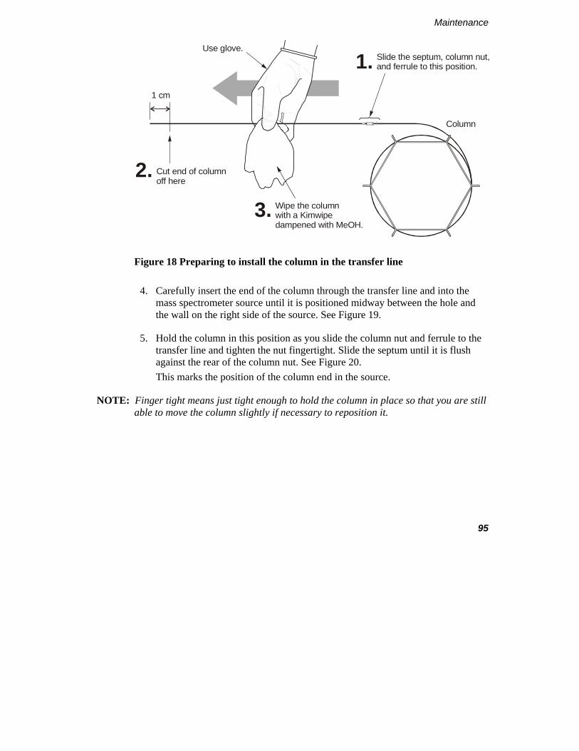
Maintenance
95
1 cm
Use glove.
Cut end of columnoff here
Column
Slide the septum, column nut,and ferrule to this position.
Wipe the column with a Kimwipedampened with MeOH.
1.
3.
2.
Figure 18 Preparing to install the column in the transfer line
4. Carefully insert the end of the column through the transfer line and into the mass spectrometer source until it is positioned midway between the hole and the wall on the right side of the source. See Figure 19.
5. Hold the column in this position as you slide the column nut and ferrule to the transfer line and tighten the nut fingertight. Slide the septum until it is flush against the rear of the column nut. See Figure 20. This marks the position of the column end in the source.
NOTE: Finger tight means just tight enough to hold the column in place so that you are still able to move the column slightly if necessary to reposition it.
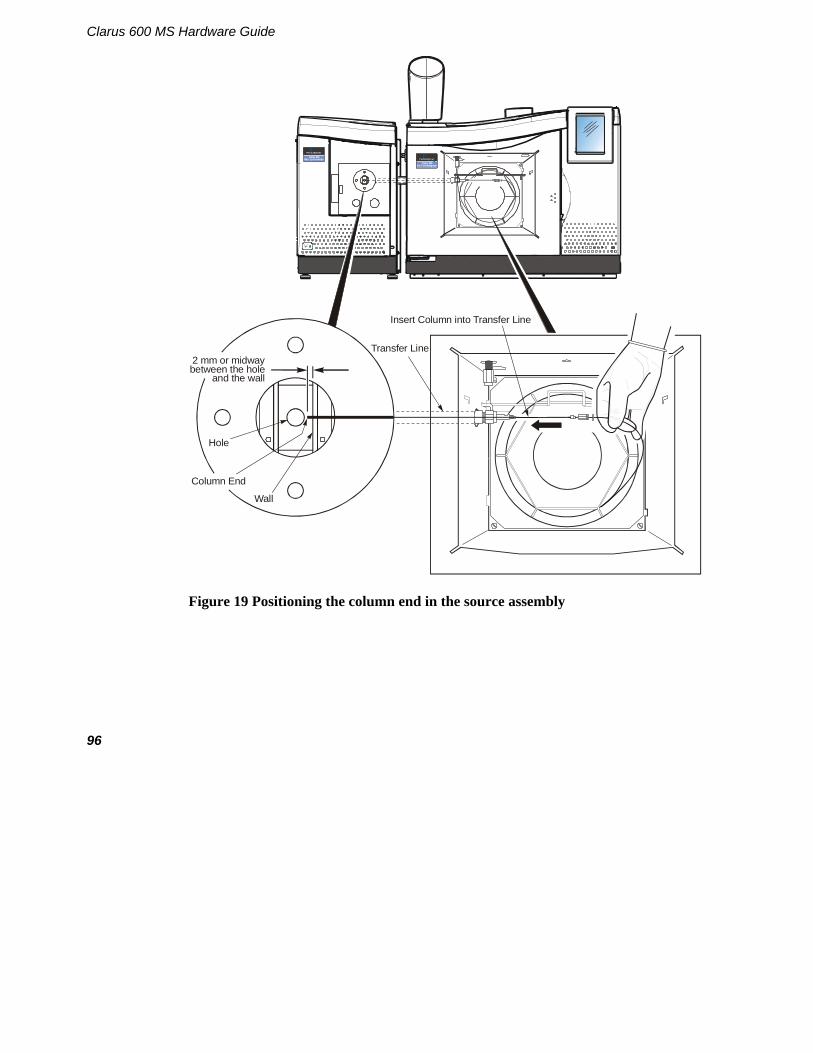
Clarus 600 MS Hardware Guide
96
Transfer Line
Insert Column into Transfer Line
2 mm or midway between the hole
and the wall
Column End
Wall
Hole
Clarus 600Gas Chromatograph
Clarus 600Mass Spectrometer
Figure 19 Positioning the column end in the source assembly

Maintenance
97
1/16-inch Column Nut1/4-inch Column Nut
Septum
Figure 20 Marking the column position in the source
6. Pull the column back until the distance between the back of the nut and septum is about 10 cm.
CAUTION
To prevent breaking the end off the column, you need to pull the column back to reinstall the source in the mass spectrometer.
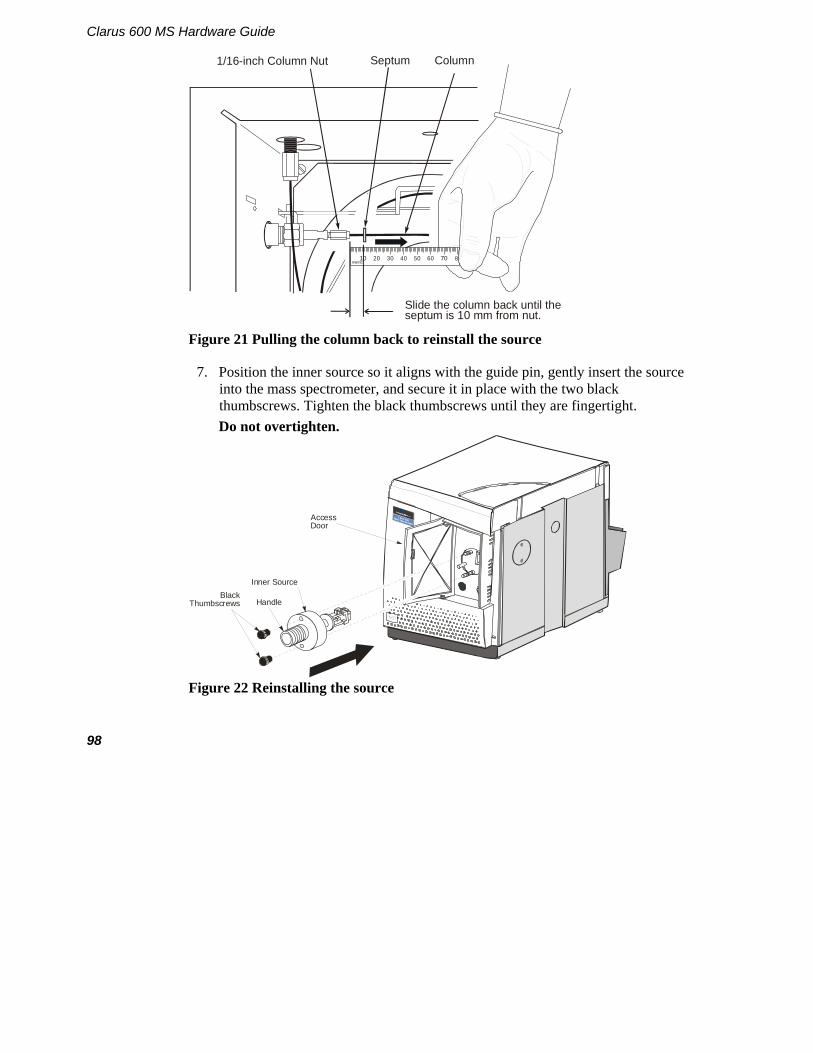
Clarus 600 MS Hardware Guide
98
metric10 20 30 40 50 60 70 8
Slide the column back until the septum is 10 mm from nut.
1/16-inch Column Nut Septum Column
Figure 21 Pulling the column back to reinstall the source
7. Position the inner source so it aligns with the guide pin, gently insert the source into the mass spectrometer, and secure it in place with the two black thumbscrews. Tighten the black thumbscrews until they are fingertight. Do not overtighten.
Inner Source
HandleBlack
Thumbscrews
Access Door
Clarus 600Mass Spectro meter
Figure 22 Reinstalling the source
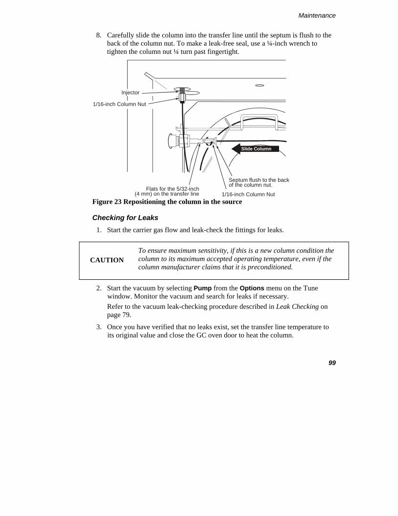
Maintenance
99
8. Carefully slide the column into the transfer line until the septum is flush to the back of the column nut. To make a leak-free seal, use a ¼-inch wrench to tighten the column nut ¼ turn past fingertight.
1/16-inch Column Nut Flats for the 5/32-inch
(4 mm) on the transfer line
Septum flush to the back of the column nut.
Slide Column
1/16-inch Column Nut
Injector
Figure 23 Repositioning the column in the source
Checking for Leaks 1. Start the carrier gas flow and leak-check the fittings for leaks.
CAUTION
To ensure maximum sensitivity, if this is a new column condition the column to its maximum accepted operating temperature, even if the column manufacturer claims that it is preconditioned.
2. Start the vacuum by selecting Pump from the Options menu on the Tune window. Monitor the vacuum and search for leaks if necessary. Refer to the vacuum leak-checking procedure described in Leak Checking on page 79.
3. Once you have verified that no leaks exist, set the transfer line temperature to its original value and close the GC oven door to heat the column.

Clarus 600 MS Hardware Guide
100
Refilling the Reference Gas Vial It is time to refill the reference gas vial when you lose reference gas peaks intensity and you do not see a liquid in the reference gas vial, or any time the mass spectrometer is vented, and the liquid in the vial level appears low.
NOTE: You should check liquid level in the reference gas vial any time you need to remove the mass spectrometer cover and vent the instrument. Using a tool such as a dental mirror will help you observe the liquid level in the Reference Gas Vial.
Items Required • Lint-free, powder-free PVC or polypropylene gloves (Part No. N621-2495).
• Pasteur Pipette or 50 µL syringe.
• Heptacosa (FC43) (Part No. N621-2407).
To refill the reference gas vial, follow this procedure:
WARNING
Make sure to vent the instrument and turn the power off.
1. Ensure that the solenoid have been switched off.

Maintenance
101
2. With the power off, unplug the source connector for more room to work. Use a 5/32 inch Allen wrench to remove the two allen nuts from the handle. See following photo.
3. With the handle off remove the reference gas vial assembly and bracket out. See the following figure.
Source Connector
Allen Nuts

Clarus 600 MS Hardware Guide
102
Figure 24 Removing the reference gas vial from the mass spectrometer
WARNING
The toxicity of the FC-43 calibrant is uncertain. Take appropriate precautions to avoid getting the calibrant on your skin or in your eyes.
4. Loosen the knurled fitting behind the gas vial by ½ turn, and pull out the vial. A black O-ring may remain in the fitting.
5. Using a pipette or syringe, add 25 to 50 µL but no more than 50 µL of Heptacosa (FC43). See the following figure. Fill the bulb. Never add more than 50 µL.

Maintenance
103
ReferenceGas Vial
Gas TightSyringe
Figure 25 Filling the reference gas vial
6. Re-insert the reference gas vial into the mass spectrometer. Make sure the O-ring is still present and the tapered end of the ferrule faces the mass spectrometer.
7. Tighten the knurled nut with your fingers until fingertight.
8. Return the bracket to the proper position and use a 5/32 inch Allen wrench to retighten the two Allen nuts to the bracket.
9. Replace the top cover and pump the system down to the proper vacuum.
10. From the Gas Menu select the Reference Gas Option from the drop down menu. Leave the Reference Gas Valve open for 60 minutes with Operate off to pump to pump out the gas from the bulb before tuning the mass spectrometer.
NOTE: On the Tune Page the Gas drop down the Pump Out Reference Gas choice no longer works. If you try to have both the Reference Gas On and the Pump Out Reference Gas options selected you will get an error message. To avoid an error message make sure to only check Reference Gas On.

Clarus 600 MS Hardware Guide
104
Inner Source Maintenance
Inner source maintenance consists of cleaning those components that contact ions. For example,
• EI source: the ionization chamber, repeller, trap, ion exit plate, and ion entry area.
• CI source: the ionization chamber, ion entry area, and ion exit plate.
CAUTION
Never clean the filament. If the filament is open, replace it by following the procedure in this chapter.
Items and Tools Required • Ultrasonic bath. • Aluminum foil or lint-free disposable cloth squares. • Aluminum oxide powder. • Wooden stick cotton swabs. • 2 mm open-end wrench (for EI source). • Tweezers. • Powder-free, lint-free gloves (Part No. N621-2495). • Small flat-blade screwdriver. • Reagent Grade acetone. • Reagent Grade methanol. • De-ionized Water • Clean 100 mL glass beaker. • 6000 Grade Micro Mesh (Part No. N930-3420). • 8000 Grade Micro Mesh (Part No. N930-3421). • 600 grit aluminum oxide in DI Water with a few drops of methanol to make a
paste

Maintenance
105
Removing the Inner Source To remove the inner source, follow this procedure:
CAUTION
Before performing source maintenance, always prepare the mass spectrometer by following the instructions in Preparing Clarus 600/560 D MS for Hardware Maintenance on page 85.
1. Prepare the mass spectrometer for maintenance as described in Preparing Clarus 600/560 D MS for Hardware Maintenance on page 85.
2. Open the GC oven door and locate the Clarus MS transfer line.
3. Using a 9/16-inch wrench, loosen the ¼-inch nut on the transfer line.
4. Pull the inner transfer line tube back 25 mm (1 inch).
1/4-inch Nut
Column
Transfer Line
Remove
Figure 26 Pulling back the transfer line

Clarus 600 MS Hardware Guide
106
5. Loosen the two thumbscrews on the inner source, grab it by its handle, pull it out of the mass spectrometer and set it on a clean surface.
6. Close the mass spectrometer access door.
7. Put on a pair of powder-free, lint-free gloves (Part No. N621-2495).
Inner Source
HandleBlack
Thumbscrews
Access Door
Figure 27 Removing the inner source
EI Inner Source Maintenance
To gain access to the parts on the EI inner source that need cleaning, follow this procedure.
NOTE: For this procedure use the Inner Source Rebuild Kit Part No. E640-0043.
CAUTION
To ensure that the mass spectrometer remains contamination free, wear lint-free, powder-free gloves (Part No. N621-2495) while performing this procedure.

Maintenance
107
Disassembling
1. Prepare a clean, uncluttered work area and place a square of aluminum foil with the shiny side up. Obtain some clean, small containers (for example, small beakers) to store the screws and small parts as you remove them.
2. Using a small flat-blade screwdriver, loosen the screw that secures the old filament assembly to the source. Use tweezers to remove the screw and washer. Pull out the filament assembly.
DefectiveFilament Assembly
Screw(P/N E531-4043)
Washer(P/N E533-1031)
Figure 28 Removing the filament assembly

Clarus 600 MS Hardware Guide
108
3. Using a small flat-blade screwdriver, loosen and remove the four screws on the ion chamber cover plate and remove the cover plate.
4. Using a 2 mm open-end wrench, loosen and remove the nut and washer that secure the repeller. Then remove the repeller.
5. Using a 2 mm open-end wrench, loosen and remove the nut and washer that secure the ion trap. Then remove the ion trap.
Clean undersideof Ion Exit Plate.(P/N E640-1213)
Clean theseareas.
Clean thisarea.
Clean thisarea.
Trap(P/N E640-1220)
6 mm Ceramic Spacer(P/N E640-1224)
2 mmSpacer(P/N E640-1222)
Screw (4)
Trap Contact(P/N E640-1217)
12 mm Spacer(P/N E640-1221)
Washer
Viton O-Ring(P/N E571-1061)
NutInsulator(P/N E640-1218)
Repeller Contact(P/N E640-1216)
Washer
Nut
6 mm Ceramic Spacer(P/N E640-1224)
Repeller(P/N E640-1219)
2 mm Spacer(P/N E640-1222)
12 mm Spacer(P/N E640-1221)
Figure 29 Removing the ion chamber cover plate and repeller

Maintenance
109
Cleaning
NOTE: You can do the following cleaning method of aluminum oxide paste or use the 6000 or 8000 grade micro mesh to polish the flat surfaces of the parts. For either cleaning method, the final step you must sonicate the parts in an ultrasonic bath of methanol for at least five minutes. Dry off the parts using lint-free tissue and/or clean compressed Nitrogen gas to prevent solvents from drying on these parts and leaving a residue
1. Mix together aluminum oxide and de-ionized water and a few drops of methanol to make a watery paste.
2. Dip a wooden-stick cotton swab in the solution and clean the darkened areas on the source. Work quickly to prevent the mixture from drying on the surface. Place the cleaned components in de-ionized water prior to rinsing to prevent drying.
Rinsing 1. Add 50 mL of acetone to a 100 mL beaker, insert the source assembly, repeller,
ion trap, ion chamber plate, and sonicate in an ultrasonic bath for ten minutes.
CAUTION
Do not allow the acetone and methanol to touch the O-ring on the source.
2. Carefully drain the acetone.
3. Add 50 mL of methanol to another 100 mL beaker, insert the source assembly, repeller, ion trap, ion chamber plate, and sonicate in an ultrasonic bath for at least ten minutes.
4. Carefully drain the methanol.

Clarus 600 MS Hardware Guide
110
Source Assembly
50 mL sonocation solutionin 100 mL Beaker
Figure 30 Rinsing the aluminum oxide from the source
5. Dry off the repeller, ion trap, source assembly and ion chamber plate using lint-free tissue and/or clean compressed Nitrogen gas to prevent solvents from drying on these parts and leaving a residue.
6. Take the parts amd wrap them in a clean, lint-free cloth and bake them in the GC oven at about 80 ºC for about fifteen minutes.
Reassembling
1. Insert the ion trap and repeller through the spacer and insulator. Then insert it into the source.

Maintenance
111
Repeller(P/N E640-1219)
2 mm Spacer(P/N E640-1222)
Ion Trap(P/N E640-1220)
2 mm Spacer(P/N E640-1222)
12 mm Spacer(P/N E640-1221)
12 mm Spacer(P/N E640-1221)
Figure 31 Inserting the ion trap and repeller into the inner source
2. Invert the source and insert a crumpled laboratory wipe into the repeller and ion trap.
3. Using tweezers, install the remaining ceramic pieces, spacers and nut first on the ion trap and then on the repeller.
4. Tighten each nut with a 2 mm open-end wrench.

Clarus 600 MS Hardware Guide
112
5. Replace the filament assembly.
6 mm Ceramic Spacer(P/N E640-1224)
Trap Contact(P/N E640-1217)
Washer(P/N E533-1013)
Nut(P/N E532-1018)
Locator(P/N E640-1218)
Repeller Contact(P/N E640-1216)
Washer(P/N E533-1013)
Nut(P/N E532-1018)
6 mm Ceramic Spacer(P/N E640-1224)
Laboratory Wipe crumpled and inserted into the ion chamber and trap areas.
Post removed to showparts assembly path
and Clarus 560 D
Figure 32 Installing the ceramics, contacts, washers and nuts on the repeller and ion trap

Maintenance
113
Rhenium Filament Assembly(P/N N6470012)
Screw
WasherContacts
Ensure filament coil aligns with hole.
Figure 33 Replacing the filament assembly
CI Inner Source Maintenance
The supplied CI inner source assembly can be used for both negative CI and positive CI. The maintenance procedures for the CI source are very similar to those of the EI; however, the CI does not have a repeller or ion trap. It does have a smaller exit aperture to ensure that the sample ions properly react with the CI gas.
CAUTION To ensure that the mass spectrometer remains contamination free, wear lint-free, powder-free gloves (Part No. N621-2495) while performing this procedure.
To gain access to the parts on the CI inner source that need cleaning, follow this procedure.
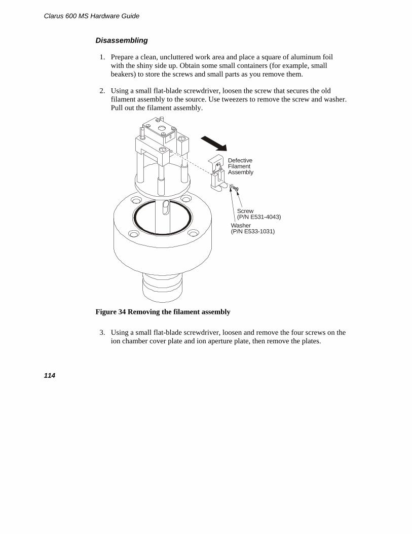
Clarus 600 MS Hardware Guide
114
Disassembling
1. Prepare a clean, uncluttered work area and place a square of aluminum foil with the shiny side up. Obtain some small containers (for example, small beakers) to store the screws and small parts as you remove them.
2. Using a small flat-blade screwdriver, loosen the screw that secures the old filament assembly to the source. Use tweezers to remove the screw and washer. Pull out the filament assembly.
DefectiveFilament Assembly
Screw(P/N E531-4043)
Washer(P/N E533-1031)
Figure 34 Removing the filament assembly
3. Using a small flat-blade screwdriver, loosen and remove the four screws on the ion chamber cover plate and ion aperture plate, then remove the plates.

Maintenance
115
Clean the undersideof the CI Ion Exit Plate(P/N E640-1214).
Underside of the Ion ExitPlate (P/N E640-1213) shown.
Clean theseareas.
Screw (1 of 4)
Figure 35 Removing the ion chamber and aperture plates and cleaning the areas shown
Cleaning NOTE: You can do the following cleaning method of aluminum oxide paste or use the 6000
or 8000 grade micro mesh to polish the flat surfaces of the parts. For either cleaning method, the final step you must sonicate the parts in an ultrasonic bath of methanol for at least five minutes. Dry off the parts using lint-free tissue and/or clean compressed Nitrogen gas to prevent solvents from drying on these parts and leaving a residue

Clarus 600 MS Hardware Guide
116
1. Mix together aluminum oxide and de-ionized water and a few drops of methanol to make a watery paste.
2. Dip a wooden-stick cotton swab in the solution and scrub the darkened areas on the source. Work quickly to prevent the mixture from drying on the surface.
Rinsing and Reassembling
1. Add 50 mL of acetone to a 100 mL beaker, insert the source assembly, ion aperture plate, ion chamber plate, and sonicate in an ultrasonic bath for ten minutes.
CAUTION
Do not allow the acetone and methanol to touch the O-ring on the source.
2. Carefully drain the acetone.
3. Add 50 mL of methanol to another 100 mL beaker, insert the source assembly, ion aperture plate, ion chamber plate, and sonicate in an ultrasonic bath for at least ten minutes.
4. Carefully drain the methanol. Source Assembly
50 mL sonocation solutionin 100 mL Beaker
Figure 36 Rinsing the aluminum oxide from the source
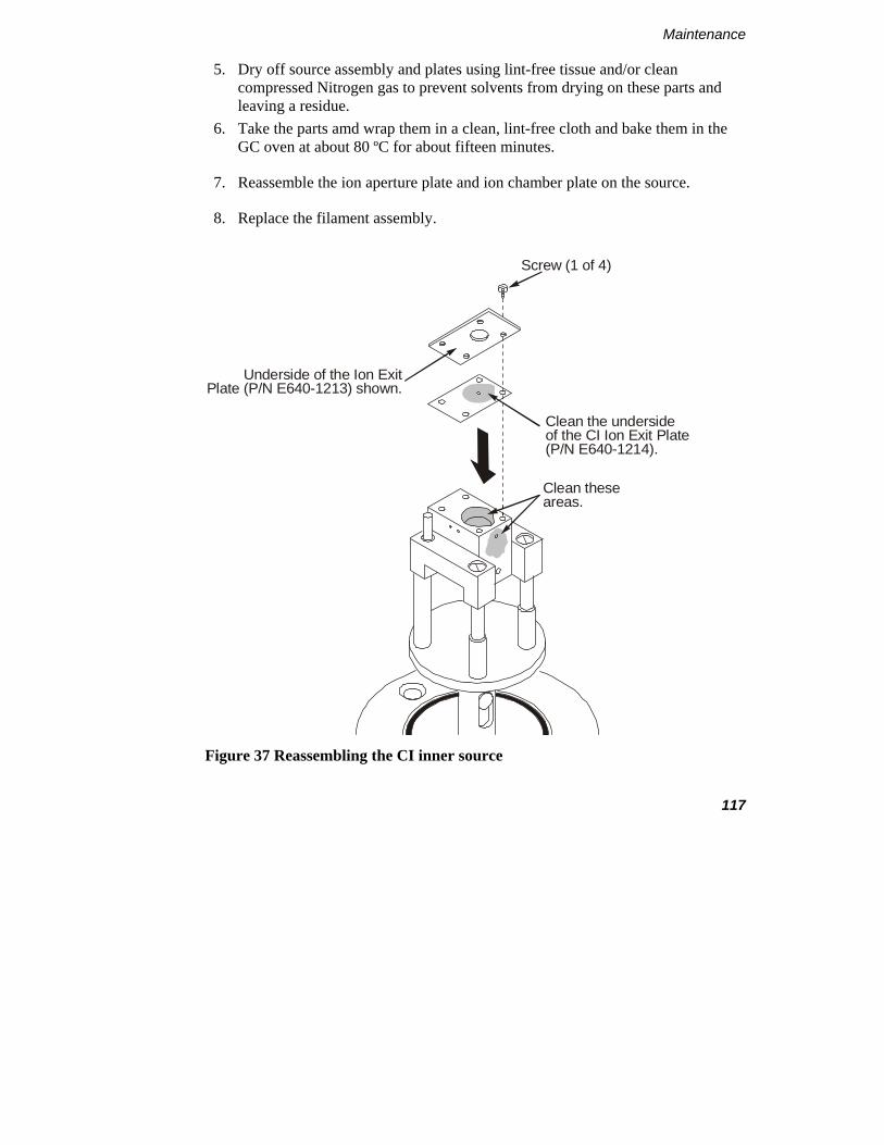
Maintenance
117
5. Dry off source assembly and plates using lint-free tissue and/or clean compressed Nitrogen gas to prevent solvents from drying on these parts and leaving a residue.
6. Take the parts amd wrap them in a clean, lint-free cloth and bake them in the GC oven at about 80 ºC for about fifteen minutes.
7. Reassemble the ion aperture plate and ion chamber plate on the source.
8. Replace the filament assembly.
Clean the undersideof the CI Ion Exit Plate(P/N E640-1214).
Underside of the Ion ExitPlate (P/N E640-1213) shown.
Clean theseareas.
Screw (1 of 4)
Figure 37 Reassembling the CI inner source

Clarus 600 MS Hardware Guide
118
Screw
WasherContacts
Ensure filament coil aligns with hole.
Rhenium Filament Assembly(P/N N6470012)
Figure 38 Replacing the filament assembly

Maintenance
119
Reinstalling the Source
1. Position the source so it aligns with the guide pin, gently insert the source into the mass spectrometer, and secure it in place with the two black thumbscrews. Tighten the black thumbscrews until they are fingertight. Do not overtighten the thumbscrews.
Inner Source
HandleBlack
Thumbscrews
Access Door
Figure 39 Reinstalling the source in the mass spectrometer
2. Insert the inner transfer line tube back in the outer transfer line.
3. Tighten the ¼ inch transfer line nut fingertight. To make a leak-free seal use a 9/16 inch wrench to tighten the ¼ inch nut an additional 1/8 turn. Tighten it enough to make a leak-free seal but do not overtighten the nut.

Clarus 600 MS Hardware Guide
120
1/4-inch Transfer Line Nut
Column
Transfer Line
Replace
Figure 40 Reconnecting the transfer line
Checking for Leaks
1. Start the carrier gas flowing and leak-check the fittings for leaks.
2. Start the vacuum by selecting Pump/Vacuum System On from the Options menu on the Tune window. Monitor the vacuum and search for leaks if necessary. Refer to the leak checking procedure described in Leak Checking on page 79.
3. Once you have verified that no leaks exist, set the transfer line temperature to its original value, and close the GC oven door to heat the column.

Maintenance
121
Replacing a Filament
CAUTION
Make sure you are wearing powder-free PVC gloves (Part No. N621-2495), and that you wipe each part with a methanol dampened Kimwipe.
Items and Tools Required • Filament assembly (Part No. E6400209).
• Tweezers.
• 0.8 mm hex wrench.
• Methanol.
• Powder-free, lint-free gloves (Part No. N621-2495).
• Small flat-blade screwdriver.
• Aluminum foil or lint-free disposable cloth squares.
To replace a filament, follow this procedure.
1. Prepare a clean, uncluttered work area and place a square of aluminum foil with the shiny side up.
2. Remove the EI source by following the procedure Removing the Inner Source as described on page 105.
CAUTION
To ensure that the mass spectrometer remains contamination free, make sure you are wearing powder-free, lint-free gloves (Part No. N621-2495), and that all tools have been cleaned with a methanol-dampened laboratory wipe.
3. Using a small flat-blade screwdriver, loosen the screw that secures the defective filament assembly to the source. Use tweezers to remove the screw and washer.
4. Pull out the defective filament assembly.

Clarus 600 MS Hardware Guide
122
DefectiveFilament Assembly
Screw(P/N E531-4043)
Washer(P/N E533-1031)
Figure 41 Removing the defective filament assembly
5. Using a 0.8 mm hex wrench, loosen the two screws that secure the contacts to the filament assembly leads. Remove the two contacts.

Maintenance
123
ContactsDefective Filiment Assembly
0.8 mmHex Wrench
Figure 42 Removing contacts from the defective filament assembly
6. Position the new filament assembly with the filament side up.
7. Insert the contacts on the new filament assembly leads so that they are flush with the white ceramic and positioned with the hex screw side facing up.
8. Secure the contacts to the filament assembly by tightening the hex screws with a 0.8 mm hex wrench. Tighten firmly but do not overtighten.
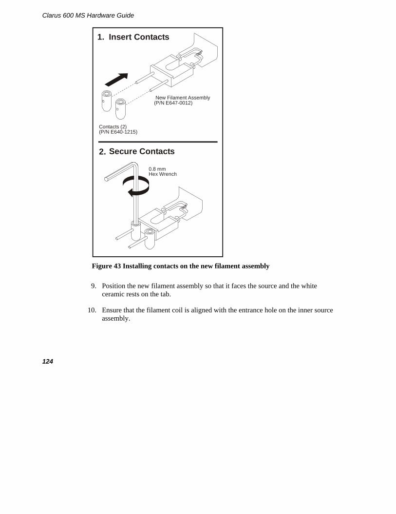
Clarus 600 MS Hardware Guide
124
Contacts (2)(P/N E640-1215)
New Filament Assembly(P/N E647-0012)
0.8 mmHex Wrench
Insert Contacts
Secure Contacts
1.
2.
Figure 43 Installing contacts on the new filament assembly
9. Position the new filament assembly so that it faces the source and the white ceramic rests on the tab.
10. Ensure that the filament coil is aligned with the entrance hole on the inner source assembly.

Maintenance
125
11. Using a small flat-blade screwdriver, secure the filament assembly in place with the screw and washer that you previously removed.
New Filament Assembly
Screw
Filament Coil
Washer
Contacts
Tab positioned between contacts.
Tab
Ensure that the filament coil aligns with the entrance hole.
Figure 44 Installing a new filament assembly on the source
12. Install the source assembly back into the mass spectrometer by following the procedure described in Reinstalling the Source on page 119.

Clarus 600 MS Hardware Guide
126
Replacing the Head Amplifier
To replace the Photomultiplier head amplifier (Part Number E649-9032), follow this procedure and refer to Figure 45:
WARNING
The mass spectrometer contains high voltage. To prevent the risk of shock, unplug the line cord from the AC outlet and wait at least one minute before opening or removing any instrument cover or panel.
1. Vent the vacuum from the mass spectrometer.
2. Turn off the mass spectrometer.
3. Unplug the AC line cords from the AC outlets.
4. Remove the four screws securing the rear panel and remove the rear panel.
5. Remove the two screws on the left side of the top panel and remove the top panel.
6. Remove the head amplifier board cover.
7. Remove the cable connector to the board.
8. Pull off head amplifier board, removing the screw with the ground wire on it.
9. Install a new board, making sure that you do not over-tighten the screw with the ground wire.
NOTE: Pins on the photomultiplier are key for proper alignment.
10. Replace the photomultiplier head amplifier board cover, cable connector, replace the panels, turn on the mass spectrometer, and pump-down the system to the proper vacuum.

Maintenance
127
11. Go to the Head Amplifier electronic adjustment procedure.
Detail of PhotomultiplierTube Pin Connections
Note keying position ofshort pin when pluggingthe Photomultiplier Tubeinto the Head AmplifierBoard
Head Amplifier Board(P/N E640-9032)
Cover
NutLockWasher
Ground Cable
Figure 45 Replacing the head amplifier

Clarus 600 MS Hardware Guide
128
Mass Analyzer Maintenance
The analyzer element of any high performance quadrupole mass spectrometer is, of necessity, a finely machined assembly that has been precisely aligned using specialized equipment. Under no circumstances should you ever disassemble the main mass analyzer assembly.
The mass spectrometer is fitted with prequads that act as a prefilter assembly designed to protect the analytical quads by intercepting the majority of any contamination. As a consequence, the analytical quads should never, under normal working conditions, require cleaning. Occasionally, it may be necessary to remove the prefilter rods for cleaning. The need to clean these rods is usually indicated by poor peak shape or loss of resolution, although other more likely causes, such as source contamination, should be eliminated first.
Items and Tools Required • 4 mm hex wrench. • 5 mm hex wrench. • Lint-free, powder-free PVC gloves (Part No. N621-2495). • Wooden stick cotton swabs. • Deionized Water • 6000 Grade Micro Mesh (Part No. N930-3420). • 8000 Grade Micro Mesh (Part No. N930-3421). • 600 grit aluminum oxide in DI Water with a few drops of methanol to make a
paste • Small flat-blade screwdriver. • Long flat-blade screwdriver. • Aluminum foil. • Acetone. • Methanol. • Tweezers.

Maintenance
129
Cleaning Materials
When cleaning internal components it is important to maintain the quality of the surface finish. Deep scratches or pits can cause loss of performance. Where no specific cleaning procedure is provided, you should use fine abrasives to remove dirt from metal components. Recommended abrasives are: • 6000 Grade Micro Mesh (Part No. N930-3420). • 8000 Grade Micro Mesh (Part No. N930-3421).
• 600 grit aluminum oxide in DI Water with a few drops of methanol to make a paste
After cleaning with abrasives, it is necessary to wash all metal components in suitable solvents to remove all traces of grease, oil and, if micro-mesh is used, rubber. The recommended procedure is to swill or sonicate the components in a clean beaker of methanol for at least ten minutes and subsequently to blot them dry with lint-free tissue. Recommended solvents are:
After the components are reassembled, they should be blown with oil-free nitrogen to remove dust particles.
Removing the Ion Optics Assembly
To remove the EI inner source, follow this procedure:
CAUTION
Before performing source maintenance, always prepare the mass spectrometer by following the instructions in Preparing Clarus 600/560 D MS for Hardware Maintenance on page 85.
1. Prepare the mass spectrometer for maintenance as described in Preparing Clarus 600/560 D MS for Hardware Maintenance on page 85.
2. Open the GC oven door and locate the mass spectrometer transfer line.
3. Using a 9/16-inch wrench, loosen the ¼-inch nut on the transfer line.

Clarus 600 MS Hardware Guide
130
WARNING
Risk of burns. Never touch a heated mass spectrometer transfer line or a GC injector cap with unprotected (bare) fingers.
4. Pull the inner transfer line tube back 25 mm (1 inch).
1/4-inch Nut
Column
Transfer Line
Remove
Figure 46 Pulling back the transfer line
5. Loosen the two thumbscrews on the inner source, grab it by its handle, gently pull it out of the mass spectrometer, and set it on a clean surface.

Maintenance
131
6. Close the mass spectrometer access door.
Inner Source
HandleBlack
Thumbscrews
Access Door
Figure 47 Removing the inner source
Removing the Mass Spectrometer Cover Panels
WARNING
The mass spectrometer contains high voltage. To prevent the risk of shock, unplug the line cord from the AC outlet and wait at least one minute before opening or removing any instrument cover or panel.
1. Turn off the Clarus GC and Clarus MS.
2. Unplug the AC line cords from the AC outlets.
3. Remove the four screws securing the rear panel, remove the rear panel, and lay it on the bench. If necessary, disconnect the fan wires.
4. When reconnecting the fan wires, make sure the fan blows the air into the mass spectrometer.

Clarus 600 MS Hardware Guide
132
5. Remove the two screws on the left side of the top panel and remove the top panel.
Screws (4)
NOTE:The rear panel vent fan should be removed from the instrument. It is removed in this illustration only to clearly show how to access the PMT Access Panel. remove the PMT Access Panel.
NOT
ONLY
Figure 48 Removing the mass spectrometer panels

Maintenance
133
Removing the Photomultiplier Tube
1. Unplug the cable from the head amplifier board.
2. Using a long flat-blade screwdriver, loosen the two captured screws securing the photomultiplier tube (PMT) amplifier cover, and remove the cover.
PMT Amp Cover
Lock Screw
NOTE:The rear panel vent fan should be removed from the instrument. It is removed in this illustration only to clearly show how to access the PMT Access Panel. remove the PMT Access Panel.
NOT
ONLY
Figure 49 Removing the PMT amplifier cover
3. Using a 4 mm hex wrench, remove the screw securing the PMT amplifier board-grounding strap.
4. Carefully remove the amplifier board from the PMT by pulling it straight back.

Clarus 600 MS Hardware Guide
134
5. Using a 4 mm hex wrench, remove the screws securing the PMT flange to the vacuum chamber.
6. Put on a pair of powder-free, lint-free gloves.
7. Carefully remove the PMT. Cover it with a laboratory wipe and place it in a safe, dark place.
8. Insert a crumpled laboratory wipe into the PMT hole in the vacuum chamber to prevent particulates from entering the vacuum chamber.
NOTE:The rear panel vent fan should be removed from the instrument. It is removed in this illustration only to clearly show how to access the PMT Access Panel. remove the PMT Access Panel.
NOT
ONLY
Head Amplifier Board(P/N E640-9032)
Cover
NutLockWasher
Ground Cable
Figure 50 Removing the head amplifier board and the PMT

Maintenance
135
Removing the Ion Optics Assembly
WARNING
Make sure to vent the instrument and turn the power off and unplug the mass spectrometer from the AC power source.
1. Disconnect the cables connected to the ion optics assembly and place them to the side so they will not interfere with the removal of the ion optics assembly. See the following figure.
2. Disconnect the Reference and CI gas lines from the top of the ion optics assembly. See the following figure.
REAR VIEW
Fan Plug
CI Gas
Reference Gas
Source
RF GeneratorCable
DynodePhosphor
Ion Optics Assembly
Location of Reference Gas Vial Assembly
Handle
Figure 51 Disconnecting cables and tubing from the ion optics assembly

Clarus 600 MS Hardware Guide
136
3. With the power off , unplug the source connector for more room to work. Use a 5/32 inch Allen wrench to remove the two allen nuts from the handle. See following photo.
4. With the handle off remove the reference gas vial assembly and bracket out and move it out to the side of the instrument. See the following photo.
Source Connector
Allen Nuts

Maintenance
137
5. Remove the four hex head bolts loosely holding the ion optics assembly to the vacuum chamber. See the following figure.
6. Grabbing the ion optics assembly by the two handles, carefully lift the ion optics assembly straight up and away. See the following figure.
Handle
Fan Plug
Guide Pins
Handle
HexagonHead Bolt (4)
Figure 52 Lifting the ion optics assembly from the vacuum manifold

Clarus 600 MS Hardware Guide
138
7. Place the ion optics assembly on a clean work surface, with the RF box down and the mass analyzer facing up (see Figure 3).
8. Cover the open vacuum chamber with aluminum foil to prevent particulates from contaminating the chamber.
Outer Source Assembly
of Ion Optics Assembly
Prequads
Analytical Quads
Figure 53 Positioning the ion optics for maintenance
Cleaning the Prequads When operating under normal circumstances, you may not have to remove the prequads from the ion optics assembly. To clean the prequads, follow this procedure.
1. Using a very fine abrasive paper (8000 grade) gently clean the ion burns off of the prefilters.

Maintenance
139
2. Wipe the prequads with a methanol dampened laboratory wipe.
3. Blow dry with helium or dry nitrogen.
Replacing an Outer Source Thermocouple
Items and Tools Required
• Thermocouple (Part No. E640-0213).
• Lint-free, powder-free PVC gloves (Part No. N621-2495).
• Small flat-blade screwdriver.
• Small adjustable wrench.
To replace the thermocouple, follow this procedure and refer to the following figure:
CAUTION
To ensure that the mass spectrometer remains contamination free, wear lint-free, powder-free gloves while performing this procedure.
1. Using a small flat-blade screwdriver, remove the screw and the thermocouple.
2. Loosen and remove the nut.
3. Remove all wires from the contact pins.
4. Pull all the wires down through the feed connector
5. Thread the new wires up through the feed connector and connect all the wires on the contact pins. Tighten the nuts.
6. Secure the new thermocouple with the screw.

Clarus 600 MS Hardware Guide
140
Remove the screw securing
thermocouple (1)(P/N E640-0213)
Secure the replacement
thermocouple with the screw.
Loosen andRemove Nut
1.
2.
7.
Feed Connector
Remove all wires from contact pins (10)
3.
Pull all wires downthrough feed connector
4.
Thread all new wires up through feed connector andconnect wires on contact pins
5.
6.TightenNut
Figure 54 Replacing the thermocouple

Maintenance
141
Removing the Outer Source from the Ion Optics To remove the outer source from the ion optics, follow this procedure (use Outer Source Rebuild Kit, Part No.E640-0042):
Position the ion optics assembly as shown.
Detach wires and tubes from outer source assembly as required.
Remove the two screws securing outer source to the ion optics.
Place the outer source assemblyon a clean work surface.
1.
2.
3. 4.
Outer Source Assembly of Ion Optics Assembly
Screw (1 of 2)(one each side)
Remove screw Disconnect wires
Remove tubes
Figure 55 Removing the outer source from the ion optics assembly

Clarus 600 MS Hardware Guide
142
Replacing Outer Source Heaters
Items and Tools Required • Two Cartridge heaters (Part No. E640-0202). • Tweezers. • Lint-free, powder-free PVC gloves (Part No. N621-2495). • Small flat-blade screwdriver.
To replace the outer source heaters, follow this procedure:
1. Position the outer source base plate on a clean work area so that the clamp plate faces up.
2. Using a flat blade screwdriver, loosen the three screws that connect to the three pillars.
CAUTION
The four ceramic rods (Part Number E640-1319) are very fragile. Use extreme care when removing the support plate and lens.
3. Carefully lift the clamp plate (Part Number E640-1322) straight up and put it aside.
4. Carefully lift and remove the contact support plate from the four ceramic rods.
5. Remove the pillar.
6. Unplug the outer source heaters from the quadrupole heater.
7. Using a flat-blade screwdriver, loosen the outer source heater setscrews.
8. Slide the old heaters out of the outer source block and insert the new heaters (Part Number E640-0202).
9. Tighten the setscrews 1/8 turn past fingertight.
Do not overtighten the setscrews.
10. Connect the heater wires together and plug the quadrupole heater wire into the remaining connector.
11. Reassemble the outer source.

Maintenance
143
Screw (1 of 3)(P/N E531-4016)
Clamp Plate(P/N E640-1322)
Contact Support Plate(P/N E640-1229)
Pillar(P/N E640-1320)
Source Heaters(P/N E640-0265)
Heater LockingScrews
Figure 56 Replacing heaters in the outer source
Clarus 600 MS Hardware Guide
144
Replacing the Quadrupole Heater
The quadrupole heater is connected in series with the two outer source heaters.
Items and Tools Required
• Cartridge heater (Part No. E640-0202).
• Small flat-blade screwdriver.
• Lint-free, powder-free PVC gloves (Part No. N621-2495).
To replace the quadrupole heater, follow this procedure:
1. Unplug the quadrupole heater wire from the outer source heater wires.
2. Loosen the setscrew that secures the quadrupole heater to the standoff.
3. Slide the heater out, discard it, and slide the new heater into the standoff.
4. Secure the heater in place by tightening the setscrew 1/8 turn past fingertight. Do not overtighten the setscrew.
5. Plug the quadrupole heater wire into the outer source heater wire connector.

Maintenance
145
Outer Source Assembly of Ion Optics Assembly
Purple wire
To outer source cartridge heater (other side)
Cartridge Heater Setscrew
To outer source cartridge heater (this side)
Quadrupole Cartridge Heater Connections
Quadrupole Cartridge Heater
(P/N E640-0266)
Figure 57 Removing the quadrupole heater

Clarus 600 MS Hardware Guide
146
Cleaning the Outer Source Lens Items and Tools Required
• 600 grit aluminum oxide.
• Tweezers.
• Methanol.
• Laboratory wipes.
• Acetone.
• Lint-free, powder-free PVC gloves (Part No. N621-2495).
• Small flat-blade screwdriver.
• Wooden stick cotton swabs.
To clean the outer source, follow this procedure:
1. Position the outer source on a clean work area so that the side with the support plate is facing up.
2. Using a flat-blade screwdriver, loosen the three screws that connect to the three pillars.
3. Carefully lift the support plate straight up and put it aside.
4. Carefully remove the Lens 2, then Lens 1 focus plates.

Maintenance
147
Cleaning
1. Mix together aluminum oxide and methanol to make a watery paste.
2. Dip a wooden-stick cotton swab in the solution and clean the darkened areas on the source. Work quickly to prevent the mixture from drying on the surface.
3. Remove the residual aluminum oxide by sonication in a beaker of methanol for ten minutes.
4. Blow dry with helium or dry nitrogen.
5. Reassemble the outer source.

Clarus 600 MS Hardware Guide
148
Lens 1 Focus Plate(P/N E640-1307)
Lens 2 Focus Plate(P/N E640-1235)
Support Plate(P/N E640-1321)
3 x 10 Screw (1)(P/N E531-4017)
3 x 6 Screw (1 of 2)(P/N E531-4016)
Pillar (1 of 3)(P/N E640-1320)
Ceramic Rod (1 of 4)
(P/N E640-1319)
5mm Ceramic Spacer (1 of 4)
(P/N E640-1325)
2mm Ceramic Spacer (1 of 4)
(P/N E640-1222)
Clean these areas.
Figure 58 Removing the lenses from the outer source for cleaning
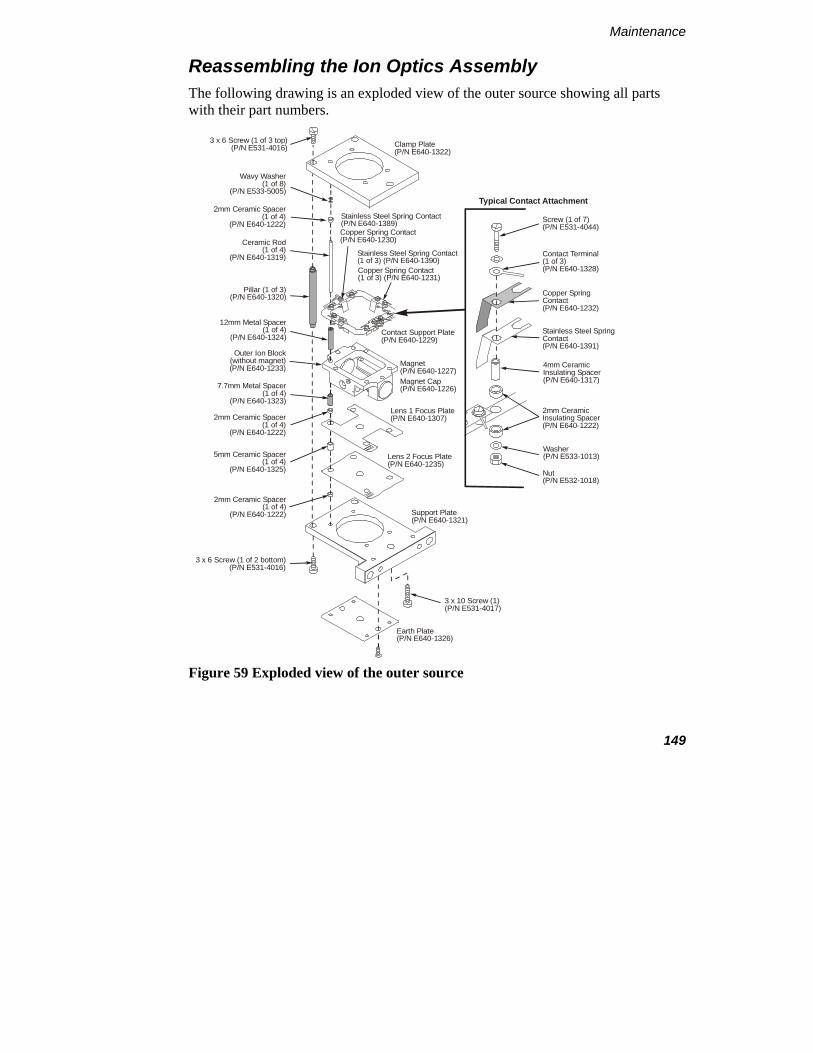
Maintenance
149
Reassembling the Ion Optics Assembly The following drawing is an exploded view of the outer source showing all parts with their part numbers.
Clamp Plate(P/N E640-1322)
3 x 10 Screw (1)(P/N E531-4017)
3 x 6 Screw (1 of 3 top)(P/N E531-4016)
3 x 6 Screw (1 of 2 bottom)(P/N E531-4016)
Contact Support Plate(P/N E640-1229)
Screw (1 of 7)(P/N E531-4044)
Contact Terminal (1 of 3)(P/N E640-1328)
Copper Spring Contact (P/N E640-1232)
Stainless Steel SpringContact(P/N E640-1391)
4mm CeramicInsulating Spacer(P/N E640-1317)
Washer(P/N E533-1013)
Nut(P/N E532-1018)
2mm CeramicInsulating Spacer (P/N E640-1222)
Outer Ion Block(without magnet)(P/N E640-1233) Magnet
(P/N E640-1227)
Copper Spring Contact(P/N E640-1230)
Copper Spring Contact (1 of 3) (P/N E640-1231)
Stainless Steel Spring Contact(P/N E640-1389)
Stainless Steel Spring Contact (1 of 3) (P/N E640-1390)
Magnet Cap(P/N E640-1226)
Lens 1 Focus Plate(P/N E640-1307)
Lens 2 Focus Plate(P/N E640-1235)
Support Plate(P/N E640-1321)
Pillar (1 of 3)(P/N E640-1320)
7.7mm Metal Spacer (1 of 4)
(P/N E640-1323)
Ceramic Rod (1 of 4)
(P/N E640-1319)
Wavy Washer (1 of 8)
(P/N E533-5005)
12mm Metal Spacer (1 of 4)
(P/N E640-1324)
5mm Ceramic Spacer (1 of 4)
(P/N E640-1325)
2mm Ceramic Spacer (1 of 4)
(P/N E640-1222)
2mm Ceramic Spacer (1 of 4)
(P/N E640-1222)
Earth Plate(P/N E640-1326)
Typical Contact Attachment2mm Ceramic Spacer
(1 of 4)(P/N E640-1222)
Figure 59 Exploded view of the outer source

Clarus 600 MS Hardware Guide
150
1. Place the assembled outer source on the ion optics assembly and secure it in place with the two screws.
2. Reattach the tubing to the outer source.
Reattach the tubes to the outer source assembly.
Place the assembled outer source on the ion optics assembly and secure it in place with the two screws.
2.
1.
Screws (2)(one each side)
Reattach tubes
Outer SourceIon Optics
Figure 60 Reinstalling the outer source
3. Using a flat-blade screwdriver, reconnect the thermocouple to the outer source.

Maintenance
151
4. Reconnect the wires to the outer source as shown in the following illustration.
Outer Source Assembly of Ion Optics Assembly
(red wire)(black wire)
Filament
Repeller(white wire)
Trap (yellow wire)Wiring Connections to the Contact Support Plate(View from Front)
Lens 1 Focus Plate (gray wire)
Purple wire
Ground(green/yellow wire)
Orange wire
To outer source cartridge heater (other side)
Contact Support Plate(See Detail)
To outer source cartridge heater (this side)
Quadrapole Cartridge Heater
Thermocouple Wires
Lens 2 Focus Plate(green wire)
Contact Ring Part No. N6470055
Figure 61 Reconnecting the wires to the outer source

Clarus 600 MS Hardware Guide
152
Reassembling the Clarus 600/560 D MS
To reassemble the mass spectrometer, follow this procedure:
1. Remove the aluminum foil covering the vacuum manifold.
2. Hold the ion optics assembly by its handles and align the guide pins with the holes in the vacuum manifold.
3. Gently lower the ion optics assembly until it is seated on the vacuum manifold.
4. Replace the four screws and tighten fingertight.
5. Remove the laboratory wipe from the PMT hole and reinstall the PMT assembly. Observe the orientation of the PMT tube as shown in the detail.
6. Insert the end of the head amplifier ground wire through one of the screws for the PMT assembly. Insert this screw into the hole in the 2 o’clock position and insert the other screw in the other hole. Tighten both screws fingertight. Using a 4 mm hex wrench, tighten both screws ¼ turn past fingertight.
7. Plug the head amplifier board onto the pins on the PMT.

Maintenance
153
Detail of PhotomultiplierTube Pin Connections
Note keying position ofshort pin when pluggingthe Photomultiplier Tubeinto the Head AmplifierBoard
Head Amplifier Board(P/N E640-9032)
Cover
NutLockWasher
Ground Cable
Figure 62 Reinstalling the PMT
8. Reinstall the PMT head amplifier cover and secure it in place with the two captured screws.
9. Replug all the cables and reconnect the tubing.
10. Reinstall the top and rear panels.
11. Reinstall the source.

Clarus 600 MS Hardware Guide
154
Vacuum System Maintenance
Vacuum system maintenance consists of the following:
• Checking the forepump to ensure the oil is at the proper level.
• Adding oil to the forepump reservoir.
• Replacing forepump oil.
• Replacing foreline trap pellets.
Complete pump instructions are in the instruction manual supplied with the pump.
Maintanenace of the Turbomolecular and Diffusion Pump
You should never service the turbomolecular and diffusion pumps. Call your PerkinElmer Service Representative for the maintenance and any problems you may have with these pumps.
Checking the Forepump Oil Level 1. Locate the oil level indicator window on the forepump.

Maintenance
155
TurboMass Connection Port
Handle
Exhaust Port
Oil Filler Plug
Drain PlugOil LevelIndicator
Gas BallastSwitch
On/OffSwitch
Mode SelectionSwitch
Max
Min
Voltage SelectionSwitch Under Cover
Figure 63 Location of the forepump oil viewing window
2. Determine if the oil level is between the Max Oil Level and Min Oil Level marks next to the window.
• If the oil level is closer to the Min Oil Level mark, add oil. Use Edwards 45 oil (Part No. 0992-3492, 1 liter).
• If it is near the scheduled six-month service, drain and refill the pump with clean oil.
• If the oil is contaminated (indicated by a darkened color), try gas ballasting and if that does not help, drain and refill the pump with clean oil.

Clarus 600 MS Hardware Guide
156
Adding Oil to the Forepump Reservoir
CAUTION
Vent the mass spectrometer before opening the plug to add oil.
1. Unscrew and remove one of the filler plugs on the top of the pump.
2. Locate the bottle of pump oil supplied with the pump and add oil until it reaches the MAX mark on the top of the sight glass. Do not overfill.
3. Replace the oil filler plug by tightening it until it is fingertight. Do not overtighten the oil filler plug.
4. After restarting the pump and allowing it to run for a few minutes, recheck the oil level. If the oil level is below the MAX mark, repeat the above procedure by adding more oil until it reaches the MAX mark.
Decontaminating the Oil The pump oil should be clear. If the oil is cloudy or discolored, it is contaminated with residual sample vapors.
1. Observe the oil in the oil sight glass.
2. Turn the mode selector fully counterclockwise to select the High Throughput mode and set the gas ballast control to the low flow (position I).
3. Run the pump until the oil appears clear.
Replacing the Oil 1. Warm the oil by running the pump for at least 10 minutes, and then switch off
the vacuum system.
2. Unplug the pump from the AC outlet and disconnect it from your vacuum system.
3. Remove one of the oil filler plugs.

Maintenance
157
Filler Plug
Drain Plug
2 Liter Drain Container
Max Oil Level
Min Oil Level
Figure 64 Draining forepump oil

Clarus 600 MS Hardware Guide
158
4. Place the pump on a table. Place a drain container under the drain plug. Raise the end of the pump opposite the drain plug by putting a block under it.
WARNING
If you were running toxic samples, the oil is contaminated as toxic waste. Handle and dispose of waste oil appropriately.
5. Remove the drain plug and allow the oil to drain into the container. If the pump oil was contaminated, pour clean oil into the filler hole and allow it to drain until the oil appears clear.
6. Replace the drain plug, remove the block and reconnect the vacuum system.
7. Add oil until it reaches the MAX mark on the top of the sight glass. Do not overfill.
8. Replace the oil filler plug by tightening it until it is fingertight. Do not overtighten the oil filler plug.
9. After restarting the pump and allowing it to run for a few minutes, recheck the oil level. If the oil level is below the MAX mark, repeat the above procedure by adding more oil until it reaches the MAX mark.

Maintenance
159
Inline Gas Purifiers
The inline gas purifier lets you change the trap without introducing contaminants into your system. This eliminates the need to flush the system. The trap contains oxygen, moisture and hydrogen adsorbents and is packed and purged under helium.
Color changes in the glass indicating trap will indicated when filter needs to be replaced.
The click on connector fitting has a spring loaded needle valve, which seals when the trap is removed and only opens when the new trap is connected and locked into position. When the click on connectors are installed into the gas line here is no need to loosen or tighten any fittings, the new trap will just click in.
Replacement Traps
Description Part No.
Indicating Glass Triple Gas specific (He) Oxygen/Moisture/Hydrocarbons
N09306107
Indicating Glass Triple Gas specific (He) Oxygen/Moisture/Hydrocarbons with 1/8” Brass Connector (2)
N09306114
Indicating Glass Triple Gas specific (He) Oxygen/Moisture/Hydrocarbons with 1/8” Steel Connector (2)
N09306116
Click On Connectors
Description Part No.
1/8” Brass Connector (2) N09306119
1/8” Steel Connector (2) N09306120
Stain steel Connector (for connecting two click on traps) N09306121
Refer to the installation instructions that accompany your new in line gas purifier trap for detailed installation and operating instructions.

Clarus 600 MS Hardware Guide
160
Changing from EI to CI Mode
Changing modes consists of the following:
• Connecting the CI gas.
• Changing the source and instrument control mode.
• Leak-checking.
• Setting-up CI.
Connecting the CI Gas
WARNING
Hazardous gas vapors. When using ammonia gas when running in the chemical ionization (CI) mode, it is necessary to vent the mass spectrometer effluent from the forepump exhaust into a fume hood or outside the building.
WARNING
Explosive Hazard. If the hydrogen is turned on without a column attached to the injector and/or detector fittings inside the oven, the gas could diffuse into the oven creating the possibility of an explosion.
If the mass spectrometer is not under vacuum, hydrogen, can fill the vacuum chamber thereby creating an explosive hazard.
To avoid possible injury, do not turn on the hydrogen, unless a column is attached, all joints have been leak-tested, and the mass spectrometer is under vacuum with the forepump exhaust properly vented to a fume hood.

Maintenance
161
Recommended Gases
Reagent gases used in chemical ionization (CI) are methane with a minimum purity of 99.999%, isobutene with a minimum purity of 99.98% and ammonia with a minimum purity of 99.998%. Carrier gas tubing should be ultra-clean.
Methane and isobutene require a gas delivery pressure of 15 psi (104 kPa) to the bulkhead fitting on the back of the mass spectrometer. A two-stage stainless steel diaphragm, high purity regulator is. A single-stage stainless steel diaphragm, high purity, rated for corrosive service is required for ammonia. Clean tubing must be used. It must be solvent-washed and nitrogen-dried. The bulkhead connector at the rear of the instrument is a 1/8 inch Swagelok fitting.
To prepare Clarus 600 MS for CI:
NOTE: Make sure to purge the CI line before you attach it to the rear of the mass spectrometer.
1. Obtain the CI gas cylinder for your analysis.
2. Connect the gas line to the CI Gas connector on the rear of the mass spectrometer.
3. Ensure that the mass spectrometer is at the proper vacuum level.
4. Turn on the CI gas and set the delivery pressure to 15 psi (104 kPa).
5. Leak-check all connections.

Clarus 600 MS Hardware Guide
162
RotaryPumpPower
Power In
Vacuum Line
ROTARY PUMP
POWER IN
Warning Labels
Warning
WATERIN
WATEROUT
NVENT
2
NHC
C HCI GAS
34
4 10H
15 psi(103 kPa)
MAX
5 psi(35 kPa)
MAX
50 psi(345 kPa)
MAX
Figure 65 CI Gas connection on the rear panel of the mass spectrometer
Changing to CI
To change from the EI to the CI mode:
1. Remove the EI inner source by following the procedure described in earlier in this chapter, Removing the Inner Source.
2. Install the CI source by following the procedure described in on page 105. Properly cover and protect the EI source and put it in a safe place.
3. Select CI+ from the Ion Mode menu. The CI+ window appears.

Maintenance
163
4. Select Pump from the Options menu. This starts the forepump and the turbomolecular pump.
5. In the Vacuum Pressure Gauges area of the window, observe the Pirani gauge time line and the Penning gauge time line. Wait about 5 minutes until the vacuum gauge achieves about 2.5 x 10⁻⁵.
Leak Checking
Before running in the CI mode, confirm that the column is properly installed and the system is leak-free. The best way to check this is by running CI without the reagent gas.

Clarus 600 MS Hardware Guide
164
To leak-check the system:
1. Display the Tune page.
2. Select CI+ from the Ion Mode menu.

Maintenance
165
3. Click Press for Operate and observe the air/water masses.
The CI source running in the CI mode without reagent gas to produce an EI emission similar to the EI mode but with reduced sensitivity. You will leak-check your system this way.
If mass 28 is larger than mass 18, you have a leak. Determine the source of the leak and correct it. For example, leak-check all fittings and connections.
Setting-Up CI
After verifying that no leaks exist, you can proceed to set up the CI mode for an analysis.

Clarus 600 MS Hardware Guide
166
Setting the Parameter Values
1. Display the following CI window:
2. Set the values as shown above. The following table describes the CI parameters to check:
Parameter: CI+ Values and Comments: Electron energy 30 eV Emission Should be below 200 µA, although 200 to 300 µA is acceptable.
(Above 200 mA may cause hydrocarbon “cracking” patterns with methane and isobutane.) Emission measures the real emission current, i.e. the source current from the source block, there is no trap "source current" in CI.
Lens 1 and 2 The tuning of these lenses may be different from the optimum values set for EI, since the source pressure is much higher in CI.
Multiplier 200V to 600V Ion Energy Approx. 1. Similar to EI. Source temperature 150 ºC

Maintenance
167
Adjust the Reagent Gas for CI+ When running in the CI+ mode with reagent gas off, the resulting EI spectra have about 10x lower sensitivity than with the EI source.
If using methane reagent gas, the reagent ions at m/z 17 (CH5+) and 29 (C2H5
+) should be of approximately equal intensity. Maximize the m/z 29 intensity. With m/z 29 maximized, the ion at m/z 16 should be about 1% of the m/z 17 peak height. (Higher indicates a leak at the transfer line/inner source connection.) Operate slightly to the low-pressure side of the maximum to minimize gas load on the MS. (The vacuum gauge pressure will be 1.5x10⁻⁴ to 5x10⁻⁴ Torr.)
If using ammonia reagent gas, reagent ions at m/z 18 (NH4+) and 35 [(NH3)2H+]
should be present and the ions at m/z 35 should be optimized.
If using isobutane reagent gas, the reagent ions at m/z 43 (C3H7+) and 57 (C4H9
+) should be tuned in the approximate ratio of 1:2.
The following example uses methane reagent gas.
NOTE: The CI gas adjustment knob controls a delicate needle valve. To avoid damaging the needle valve, do not overtighten it. Always use the CI gas button on the screen to turn off the CI gas.

Clarus 600 MS Hardware Guide
168
Access Door
Black Knurled Knobs
Inner Source
Figure 66 CI reagent gas needle valve adjustment knob
1. Carefully turn the delicate CI Gas adjustment knob fully clockwise until you feel it stop.
2. Select CI Gas On from the Gas menu. A check mark appears next to the option.
NOTE: Always turn on the CI gas before Operate to avoid a pressure surge hitting the filament.

Maintenance
169
3. Click Press for Operate and monitor the Penning gauge as you adjust the CI gas. Observe that mass 16 initially grows larger. As pressure increases in the ion chamber of CI source, the mass 29 peak will begin to grow. Keep the pressure below 5 e-4 Torr.
4. When using methane gas, carefully turn the CI adjustment knob counterclockwise until m/z 16 is low or non-existent, and m/z 29 is maximized. As you turn the knob, reduce the multiplier voltage to keep the peaks on scale. A typical multiplier value is 235. m/z 17 and 29 will typically be 80 – 100%.
5. Continue to turn the knob counterclockwise. Observe that the pressure increases and mass 41 will start to grow. Stop when mass 29 is at 100%.
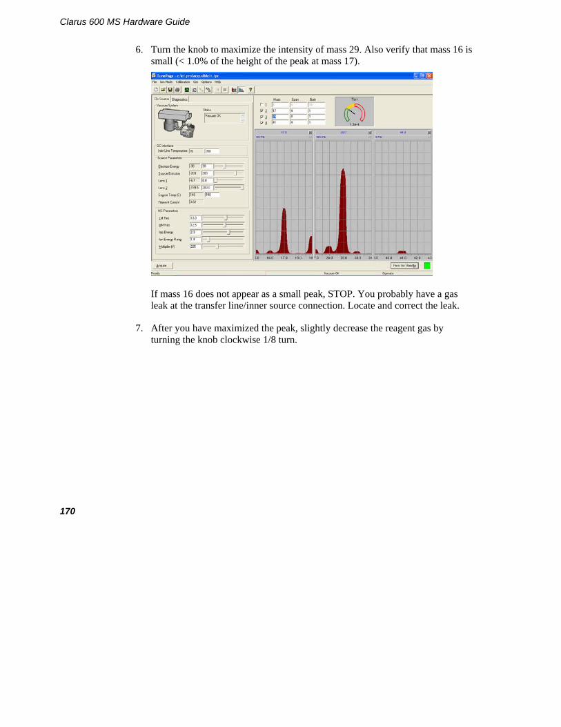
Clarus 600 MS Hardware Guide
170
6. Turn the knob to maximize the intensity of mass 29. Also verify that mass 16 is small (< 1.0% of the height of the peak at mass 17).
If mass 16 does not appear as a small peak, STOP. You probably have a gas leak at the transfer line/inner source connection. Locate and correct the leak.
7. After you have maximized the peak, slightly decrease the reagent gas by turning the knob clockwise 1/8 turn.
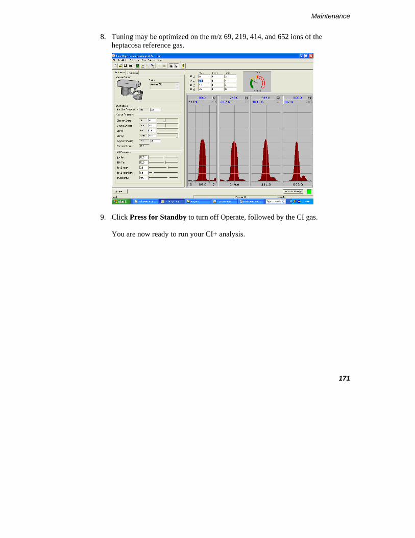
Maintenance
171
8. Tuning may be optimized on the m/z 69, 219, 414, and 652 ions of the heptacosa reference gas.
9. Click Press for Standby to turn off Operate, followed by the CI gas.
You are now ready to run your CI+ analysis.

Clarus 600 MS Hardware Guide
172
Adjust the Reagent Gas for CI-
1. Open the CI gas inlet by selecting CI Gas from the Gas menu. Wait at least 10 seconds before clicking Press for Operate. Parameter: CI− value and comments: Electron Energy 30 to 70 eV
(This parameter should be optimized.) Emission 200 to 300 μA is acceptable
(Emission measures the real emission current, i.e. the source current from the source block, there is no separate measurement of source current in CI.)
Lens 1 and 2 The tuning of these lenses may be different from the optimum values set for EI, since the source pressure is much higher in CI.
Multiplier 200V to 600V Source temperature 150 °C is standard. Higher temperatures keep
the source cleaner, but may increase fragmentation. For example, down a little from EI to minimize fragmentation. 120 °C is the practical lower limit.
Ion Energy Approx. 1 or 2
2. Optimize the amount of reagent gas flowing into the source by using two heptacosa ions, m/z 452 and 633, which usually produce relative intensities of 65 – 85% and 95% respectively. Heptacosa can be used to calibrate the m/z range for negative ion CI analyses.
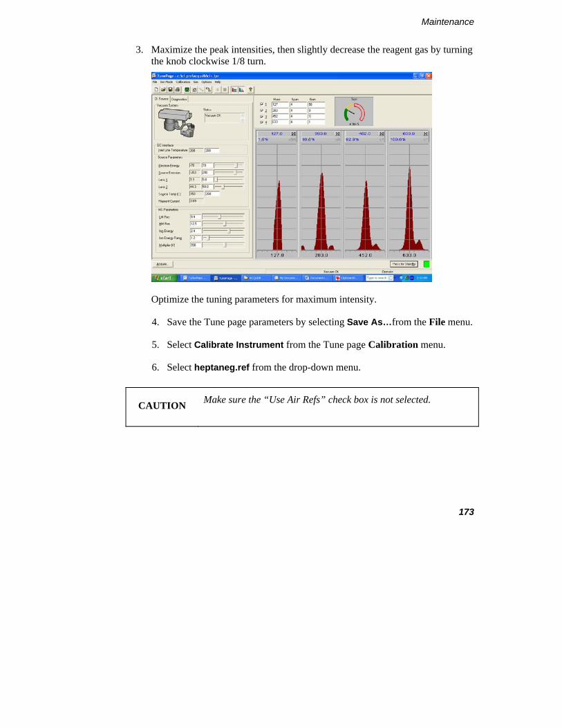
Maintenance
173
3. Maximize the peak intensities, then slightly decrease the reagent gas by turning the knob clockwise 1/8 turn.
Optimize the tuning parameters for maximum intensity.
4. Save the Tune page parameters by selecting Save As…from the File menu.
5. Select Calibrate Instrument from the Tune page Calibration menu.
6. Select heptaneg.ref from the drop-down menu.
CAUTION Make sure the “Use Air Refs” check box is not selected.

Clarus 600 MS Hardware Guide
174
7. Click the Start button to display the following dialog box.
8. Click Acquisition Parameters and enter the following values.
9. Click OK to begin calibration.
You are now ready to run CI analysis.

Troubleshooting 5

Clarus 600 MS Hardware Guide
176

Overview
The following sources of problems can occur in gas chromatography and mass spectrometry:
• The operator: When the operator is new to chromatography/mass spectrometry and/or a new instrument, problems can be introduced during the learning curve. Once the operator becomes familiar with both the technique and the instrument, this problem source diminishes greatly.
• The sample: Unlike clean standards, real world samples such as environmental samples can introduce problems because they are difficult to handle, have complicated matrices, contain unknown constituents, etc.
• The column: The column is most often the major factor contributing to poor analyses. The more a column is used, the greater the possibility of contamination, loss of substrate, etc. Columns do not last forever and should be changed when results become suspect.
• The gas flow system: Gas leaks are a major concern in gas chromatography and can lead to many problems.
• The vacuum system: Vacuum leaks are a major concern in mass spectrometry and can lead to many problems.
• Ion Optics: Over time, the ion optics can become contaminated. This results in reduced sensitivity and difficult or impossible tuning.
• The electronics: The problem must be identified as either chromatographic or hardware. Electronics used in the system can malfunction.
• Data handling: Today, most chromatographers rely on sophisticated data handling systems to integrate their results. Some problems can be related to the incorrect data handling parameter settings or hardware problems with the computer.

Clarus 600 MS Hardware Guide
178
Spare Components The following list contains items you should have on hand to help solve problems.
• New syringes: a syringe can break, become plugged or begin leaking. Always have spare syringes available.
• Duplicate columns: a column does not last forever; always have a duplicate column on hand in the event that your separation begins to degrade. Also, capillary columns can be damaged if oxygen is introduced at high temperatures. A duplicate column will allow you to determine if the column is the cause of the problem.
• Septa: this is the one area of the gas chromatograph that requires routine maintenance. Always have spare septa available.
• Leak detector: the gas flow system can be a problem as fittings wear with age and can begin to leak. You should have a thermal conductivity leak detector to help find and fix leaks.
• Injector liners: are made of glass or fused silica and can be easily broken when removed. You should keep a supply of spare liners on hand. Please remember that you cannot run satisfactory analyses without an injector liner.
Logical Troubleshooting Steps There are some simple steps that you should take when trying to locate a problem. Use the following guide to troubleshoot your system.
1. Note the symptoms - define the problem. Compare your runs with good analysis, that is, with the results normally obtained.
2. Systematically eliminate possible causes. The first rule here is, "What did you change last?" Many times a problem arises when a change is made to the system, such as changing a gas tank, column, septum or glass liner. If the problem occurred after such a change, then the change is the most likely cause of the problem. Change the simplest thing first. For example, if you suspect a gas leak, the easiest change to make is the GC septum instead of replumbing the internal pneumatics.

179
Change only one parameter at a time and check for its effect. If you change three items at once and your problem goes away, you may not know which of the three moves or combination of moves corrected the problem. This way, if the problem happens again, you will know exactly what corrective action to take.

Clarus 600 MS Hardware Guide
180
Troubleshooting Chart
Problem Probable Cause Solution
Mass Spectrometer will not turn on (no indication of power to the instrument).
AC line cord not plugged into an AC outlet.
Plug the Mass Spectrometer AC line cord into an AC outlet.
No AC power to the outlet. Check the outlet.
Fuse blown. Call a PerkinElmer service engineer.
Mass Spectrometer is on but the forepump is not running.
Forepump is not plugged into the AC outlet on the rear of the mass spectrometer.
Plug the forepump line cord into the mass spectrometer.
Forepump is not operating correctly ( mass spectrometer does not pump down).
Make sure the forepump is switched on.
Blown fuse in Mass Spectrometer.
Call a PerkinElmer service engineer.

181
Problem Probable Cause Solution
The ultimate pressure is poor.
Is the cooling inadequate?
Check the cooling-air flow and correct if possible.
Check the cooling-air duct for obstructions and correct as necessary.
If the cooling air flow is fine and there are no obstructions contact your PerkinElmer service representatives.
Is the backing pressure high?
Check for a leak in the backing pipeline and poor backing pump performance. Correct as necessary.
The pump is very noisy or there is excessive vibration or both.
Is the noise irregular and getting progressively worse?
If so, a bearing may be defective. Contact your PerkinElmer service representative.
Is the pump making a constant high pitched noise?
If so, the rotor may be out of balance. Contact your PerkinElmer service representative.

Clarus 600 MS Hardware Guide
182
Problem Probable Cause Solution
Turbo pump will not accelerate
Pump malfunction. Call a PerkinElmer service engineer.
Pump controller malfunction.
Call a PerkinElmer service engineer.
GC is not properly configured.
Set the proper GC configuration for your site.
Vacuum light continues to blink.
Large leak. Locate vacuum leak and correct.
Foreline trap has excessive moisture.
Replace filter.
Rotary pump set to gas ballast.
Switch the gas ballasting off.
Rotary pump requires oil change.
Change oil.
High mass spectra appears as a large blotch, or loss of high mass spectra.
Bad tune. Run AutoTune.
Drastic change in mass peak shape for no apparent reason.
Bad tune. Run AutoTune.
No spectra, or large blotch. Bad tune. Run AutoTune.

183
Problem Probable Cause Solution
No spectra, or very little spectra at the low mass end.
Bad tune. Run AutoTune.
No spectra, not even noise at a high PMT voltage.
Loose electrometer cable. Reset the cable.
Defective electrometer board.
Call a PerkinElmer service engineer.
No filament current. Defective filament. Replace the filament.
Wavering baseline (by several hundred counts).
Defective outer source temperature sensor or a defective electrometer.
Replace the temperature sensor.
Call a PerkinElmer service engineer.

Clarus 600 MS Hardware Guide
184
Problem Probable Cause Solution
Poor or inadequate sensitivity.
Leaking injector septum. Replace the septum.
Leak from injector ferrules.
Tighten/replace ferrules.
Foreign material in the injector.
Clean the injector.
Peak splitting. Prevent double injections.
Dry the outside of the injector needle.
Replace the injector septum.
Injector and column are more active toward acid/base compounds.
Install a silanized injector liner, or silanize the current injector liner.
Check or replace the injector packing material, such as quartz wool.
Cut off the first 30 cm of the column and rerun the test mix. If the results do not improve replace the column.

185
Problem Probable Cause Solution
Solvent tailing. Inadequate splitter flow. Increase the splitter flow.
Column not properly installed in the injector.
Reinstall the column in the injector.
Loss of high end compounds. Temperature setting too low on the injector, column oven or transfer line.
Increase the injector, column oven or transfer line temperature to allow the less volatile compounds of the sample to reach the mass spectrometer.
Peaks at masses 28 (nitrogen) and 32 AMU (oxygen) are in a ratio of < 4 to 1, and the peak at mass 28 is larger than the peak at mass 18.
Leaks in or around vacuum or column fittings.
Tighten the fittings and connection points to the high vacuum system.
Set the injector split flow to 50:1.
Peaks at masses 14 and 16 are larger than the peak at mass 28.
Leaks or improper tuning. Tighten the fittings and connection points to the high vacuum system.
Set the injector split flow to 50:1.
Run AutoTune.

Clarus 600 MS Hardware Guide
186
Problem Probable Cause Solution
Poor sensitivity (correct amount of sample is reaching the mass spectrometer).
Column is improperly positioned in the ion source.
Reinstall the column and check the cut at the end that fits in the source.
Improper tuning, or a dirty or defective ion source.
Check the tuning. Increase the PMT voltage.
Shut down the system, remove the inner source, clean or replace lenses in the outer source, and install a new filament.
Loss of resolution (especially at high mass).
Dirty prequadrupole rods. Clean the prequadrupole rods.
Mass assignment drifts. Large temperature fluctuations in the laboratory.
Stabilize the lab temperature, or isolate the GC/MS system from large temperature fluctuations.
Mass assignment incorrect. Run mass calibration.
Skewed spectra. Improper scan speed (too slow for the narrow peaks produced by capillary columns).
Increase the scan speed.
Unusually high repeller voltage.
Repeller dirty. Clean repeller.
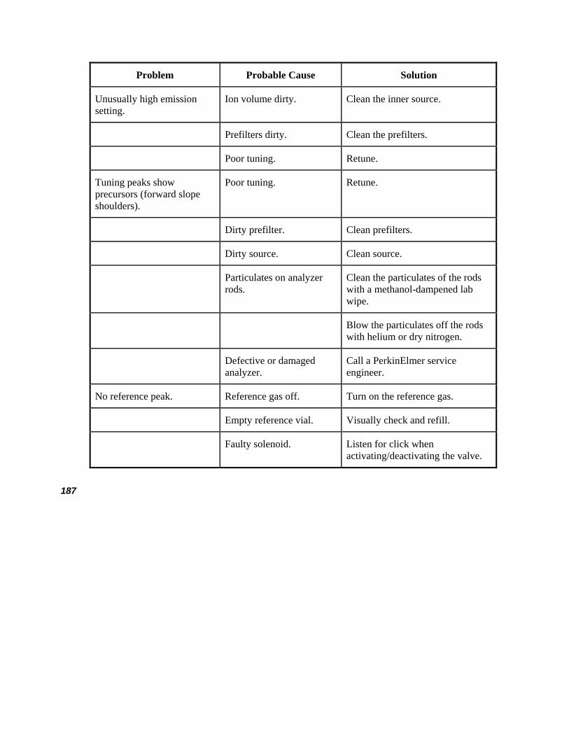
187
Problem Probable Cause Solution
Unusually high emission setting.
Ion volume dirty. Clean the inner source.
Prefilters dirty. Clean the prefilters.
Poor tuning. Retune.
Tuning peaks show precursors (forward slope shoulders).
Poor tuning. Retune.
Dirty prefilter. Clean prefilters.
Dirty source. Clean source.
Particulates on analyzer rods.
Clean the particulates of the rods with a methanol-dampened lab wipe.
Blow the particulates off the rods with helium or dry nitrogen.
Defective or damaged analyzer.
Call a PerkinElmer service engineer.
No reference peak. Reference gas off. Turn on the reference gas.
Empty reference vial. Visually check and refill.
Faulty solenoid. Listen for click when activating/deactivating the valve.

Clarus 600 MS Hardware Guide
188
Problem Probable Cause Solution
Inconsistent peak widths. Poor tubing. Retune.
Ground loop from GC and MS on different power supplies.
Unify supplies.
Peaks shifted from their nominal mass position.
Poor calibration. Perform mass calibration.
Tuned peaks are too narrow. Over-resolved tuning. Retune.
Tuned peaks are too wide. Under-resolved tuning. Retune.
Big peaks observed at m/z 18, 28, 32.
Air leak developed. Check column connections.
Change carrier gas tank. Fit oxygen scrubber.
Moisture from recent source clean/column change.
Bake out source overnight.
No ion beam but the filament status OK.
Large air leak. See procedure for leak-checking.
Detector voltage too low. Increase PMT value.
Electronics failure. Call a PerkinElmer service engineer.
Poor sensitivity. Beam instability/peaks breaking up.
Column improperly installed.
Check and reinstall the column if necessary.

189
Problem Probable Cause Solution
Piece of column broken off in the ion chamber.
Remove the inner source, check for and remove piece of column.
Source filament is bent. Check and replace filament if necessary.
RF generator malfunction. Call a PerkinElmer service engineer.
Analyzer drive electronics malfunction.
Call a PerkinElmer service engineer.
Total Ion Chromatogram too high.
Dirty source. Clean the source.
Contamination from poor handling technique.
Set source and transfer line to 250 ºC and maintain this temperature overnight.
Stationary phase of column de-polymerizing (bleeding).
Change column.
Air leak. Find the leak and fix it.
Poor quality carrier gas. Replace the carrier gas tank.
Carrier gas filter is ineffective and needs replacing.
Replace the carrier gas filter.
No noise on mass chromatogram.
Detector multiplier voltage too low.
Increase the multiplier voltage.
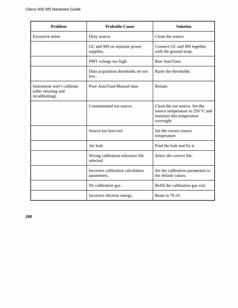
Clarus 600 MS Hardware Guide
190
Problem Probable Cause Solution
Excessive noise. Dirty source. Clean the source.
GC and MS on separate power supplies.
Connect GC and MS together with the ground strap.
PMT voltage too high. Run AutoTune.
Data acquisition thresholds set too low.
Raise the thresholds.
Instrument won’t calibrate (after retuning and recalibrating).
Poor AutoTune/Manual tune. Retune.
Contaminated ion source. Clean the ion source. Set the source temperature to 250 ºC and maintain this temperature overnight.
Source too hot/cool. Set the correct source temperature.
Air leak. Find the leak and fix it.
Wrong calibration reference file selected.
Select the correct file.
Incorrect calibration calculation parameters.
Set the calibration parameters to the default values.
No calibration gas. Refill the calibration gas vial.
Incorrect electron energy. Reset to 70 eV.
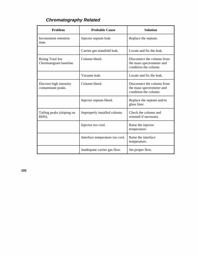
191
Chromatography Related
Problem Probable Cause Solution
Inconsistent retention time.
Injector septum leak. Replace the septum.
Carrier gas manifold leak. Locate and fix the leak.
Rising Total Ion Chromatogram baseline.
Column bleed. Disconnect the column from the mass spectrometer and condition the column.
Vacuum leak. Locate and fix the leak.
Discreet high intensity contaminant peaks.
Column bleed. Disconnect the column from the mass spectrometer and condition the column.
Injector septum bleed. Replace the septum and/or glass liner.
Tailing peaks (sloping on RHS).
Improperly installed column. Check the column and reinstall if necessary.
Injector too cool. Raise the injector temperature.
Interface temperature too cool. Raise the interface temperature.
Inadequate carrier gas flow. Set proper flow.

Clarus 600 MS Hardware Guide
192
Problem Probable Cause Solution
Dirty injector liner. Clean or replace.
Column has active sites. Equilibrate or replace.
Chromatographic peaks too wide.
Injector too cool. Raise injector temperature.
Sample overloading the column.
Use a split injection or a smaller sample.
Incorrect GC oven program. Enter a new oven program.
Discrimination of relative peak intensities.
Poor resolution or improper tuning.
Retune.
Unstable filament. Replace filament.
Poor calibration. Recalibrate.
Air leaks at detector. Check He/Air ratio.
Peaks are flat-topped. Signal strength exceeds dynamic range of detector.
Reduce PMT voltage.
Sample is too strong. Dilute or split.
High baseline. Dirty sample. Prepare and filter a new sample.
Air leak at injector. Locate and fix the air leak.
Contaminated carrier gas. Replace the gas tank.

193
Problem Probable Cause Solution
Slowly falling baseline (from a high initial value).
Split valve left closed during acquisition.
Open the split valve.
Inadequate purge flow rate. Increase flow rate.
Poor off for too long. Reduce purge time.
Low sensitivity. Dirty source. Clean the source.
Poor column performance. Replace column.
Dirty injector. Replace injector liner.
Source temperature not optimized.
Set the proper source temperature.
Detector voltage set too low. Increase PMT voltage.
Tune not set correctly. Run AutoTune.
Poor filament alignment. Realign or replace filament.
Incorrect column position in the source.
Reposition the column.

Clarus 600 MS Hardware Guide
194
Problem Probable Cause Solution
Poor reproducibility. Dirty source. Remove and clean the source.
Defective injector liner. Replace injector liner.
Defective syringe. Replace syringe.
Old or damaged filament. Examine and replace filament.
Poor tuning. Retune.
Poor calibration. Recalibrate.
Air leak. Locate and fix.
Active sites in column/liner. Replace column/liner.
Intermittent source heater failure.
Call a PerkinElmer service engineer.
Poor S/N on test standards. See low sensitivity causes above.
Incorrect GC/MS method Use the correct method.
Accidental split injection. Set the proper split.
Detector voltage set too low. Increase PMT voltage.
Column flow rate too high. Reset the column flow rate.

195
Spectral Related
Problem Probable Cause Solution
Noisy spectra. Dirty source. Remove and clean the source.
Peak detection threshold set too low. Raise the thresholds.
PMT voltage set too high. Lower the PMT voltage.
Spectrum distortion. Scanning too fast or slow. Reset the scan rate.
Incorrect Isotope ratios. Poor calibration. Recalibrate.
Incorrect tune. Retune.
Defective filament. Replace filament.
Air leak. Find and fix.
Missing Isotopes in spectrum.
Bad calibration. Recalibrate.
Poor tuning. Retune.
Dirty source. Clean source.
Sample too weak. Use a higher sample concentration.
Peak detection thresholds set too high.
Lower the thresholds.
PMT voltage set too low. Raise the PMT voltage.
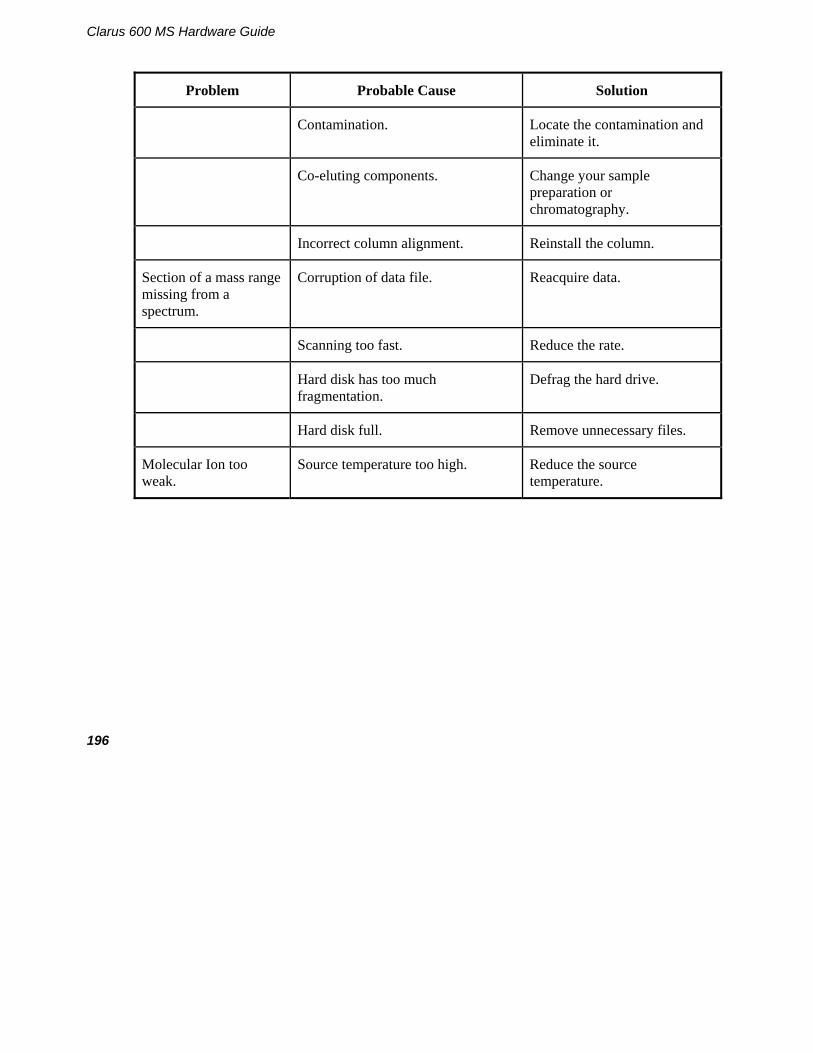
Clarus 600 MS Hardware Guide
196
Problem Probable Cause Solution
Contamination. Locate the contamination and eliminate it.
Co-eluting components. Change your sample preparation or chromatography.
Incorrect column alignment. Reinstall the column.
Section of a mass range missing from a spectrum.
Corruption of data file. Reacquire data.
Scanning too fast. Reduce the rate.
Hard disk has too much fragmentation.
Defrag the hard drive.
Hard disk full. Remove unnecessary files.
Molecular Ion too weak.
Source temperature too high. Reduce the source temperature.

197
Communications Related
Problem Probable Cause Solution
Will not boot MS. PC (computer) to MS cable has a loose connection.
Check and reset the cable.
Transient in power supply has halted communications.
Reboot the PC (computer).
Will not control GC. RS 232 communications cable loose connections.
Check and restart the mass spectrometer.
Power failure/transient surge to GC or autosampler.
GC electronic malfunction. Call a PerkinElmer service engineer.
Communication cable intermittent contact.
GC electronics malfunction.
Call a PerkinElmer service engineer.
Crashes when starting an acquisition.
Software corrupted. Reload software.
Rotary pump malfunction. Call a PerkinElmer service engineer.

Clarus 600 MS Hardware Guide
198
Forepump Related
Problem Probable Cause Solution
Pump does not start. Forepump switched off. Switch on the pump.
Blown fuse. Call a PerkinElmer service engineer.
Electrical supply voltage does not match that of the pump motor.
Determine the correct voltages, and correct. Check the voltage switch at the pump.
The outlet filter is blocked.
Find and unblock.
Pump has failed to reach vacuum.
Pressure measurement or gauge head gives an incorrect indication of pressure.
A contaminated Pirani gauge can indicate a pressure several times higher that the actual. Replace if necessary.
Pump contains the wrong type of oil.
Drain and refill with the correct oil - Edwards Ultragrade 19 Oil. Consult your Edwards Pump instruction manual.
Mode selector and/or gas ballast control are incorrectly set.
Check and set to correct position.
High oil level. Drain to the high oil level mark.
Low oil level. Check and fill to correct level.

199
Problem Probable Cause Solution
Contaminated oil. Drain and refill with new oil.
Vacuum fitting dirty or damaged.
Check and replace if necessary.
Noisy Pump. Motor fan cover damaged. Call a PerkinElmer service engineer.
Worn motor bearings. Call a PerkinElmer service engineer.
Oil contaminated with solid particles.
Determine cause and replace oil.
Oil saturated from CI analysis.
Drain and refill with clean oil.

Clarus 600 MS Hardware Guide
200
Problem Probable Cause Solution
External oil leak. Outer shaft seal worn or damaged.
Call a PerkinElmer service engineer.
Oil box gaskets deteriorated. Call a PerkinElmer service engineer.
Oil leak from gas ballast control.
Call a PerkinElmer service engineer.
Oil leak from drain plug. Tighten the drain plug or replace.
Oil leak from sight glass. Tighten sight glass screws or call a PerkinElmer service engineer.

201
Message Dialogs
When operating the instrument message dialog boxes will sometimes appear. The following table is the Icon Key followed by tables that show the Message Title, icon, dialog message and recommended action.
Icon Key
Icon Meaning
Press this icon to close the message.
Press this informational icon to get more details on the message.

Clarus 600 MS Hardware Guide
202
Message Title Icon Message Action
Diffusion pump failure
There is a problem with the diffusion pump. Either the diffusion pump fan has failed or the pump has over heated. Please look in the Hardware Guide for additional instruction.
Press OK to close the message. Check the cooling-air flow and correct if possible. Check the cooling-air duct for obstructions and correct as necessary. If the cooling air flow is fine and there are no obstructions contact your PerkinElmer service representatives.
System not at pressure
Caution
The system has not reached the proper operating pressure. The filament could be damaged by starting the system now. Do you wish to continue?
Press Yes if you wish to continue.
Press No if you wish to stop.
See the Maintenance chapter in this Hardware Guide for the procedure to replace a filament.
Safe to vent
The vacuum system is off and the system can now be vented. The GC carrier gas should be turned off.
Press OK to close the message.

203
Message Title
Icon Message Action
Diffusion Pump failure
There is a problem with the diffusion pump. Either the diffusion pump fan has failed or the pump has over heated. Please look in the Hardware Guide for additional instruction.
Press OK to close the message.
Check the cooling-air flow and correct if possible. Check the cooling-air duct for obstructions and correct as necessary.
If the cooling air flow is fine and there are no obstructions contact your PerkinElmer service representatives.
Vacuum Leak Detected
The backing pump could not reach the necessary vacuum level to start the diffusion pump. There could be a problem with a vacuum leak, the backing pump or the vacuum gauge. The backing pump will be turned off. Make sure that the vent valve is closed before restarting the backing pump.
Press OK to close the message.
Check the system for any leaks and correct. If the problem continues contact your PerkinElmer service representatives.
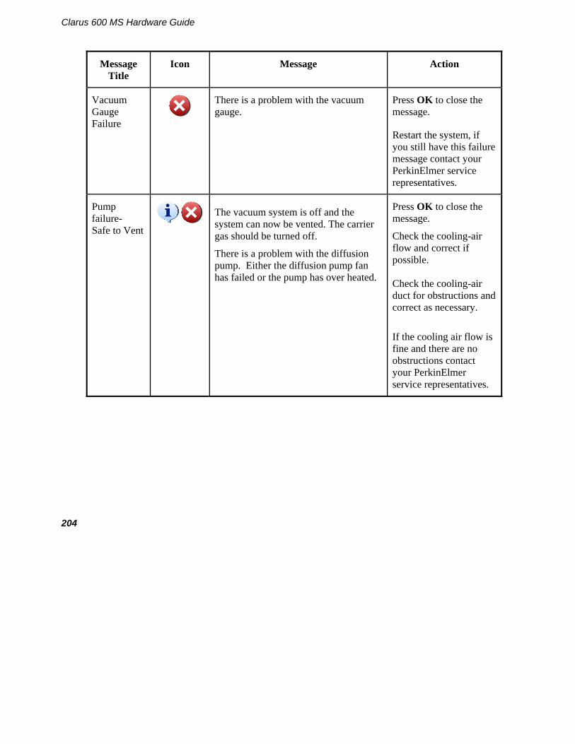
Clarus 600 MS Hardware Guide
204
Message Title
Icon Message Action
Vacuum Gauge Failure
There is a problem with the vacuum gauge.
Press OK to close the message.
Restart the system, if you still have this failure message contact your PerkinElmer service representatives.
Pump failure- Safe to Vent
The vacuum system is off and the system can now be vented. The carrier gas should be turned off.
There is a problem with the diffusion pump. Either the diffusion pump fan has failed or the pump has over heated.
Press OK to close the message.
Check the cooling-air flow and correct if possible. Check the cooling-air duct for obstructions and correct as necessary.
If the cooling air flow is fine and there are no obstructions contact your PerkinElmer service representatives.
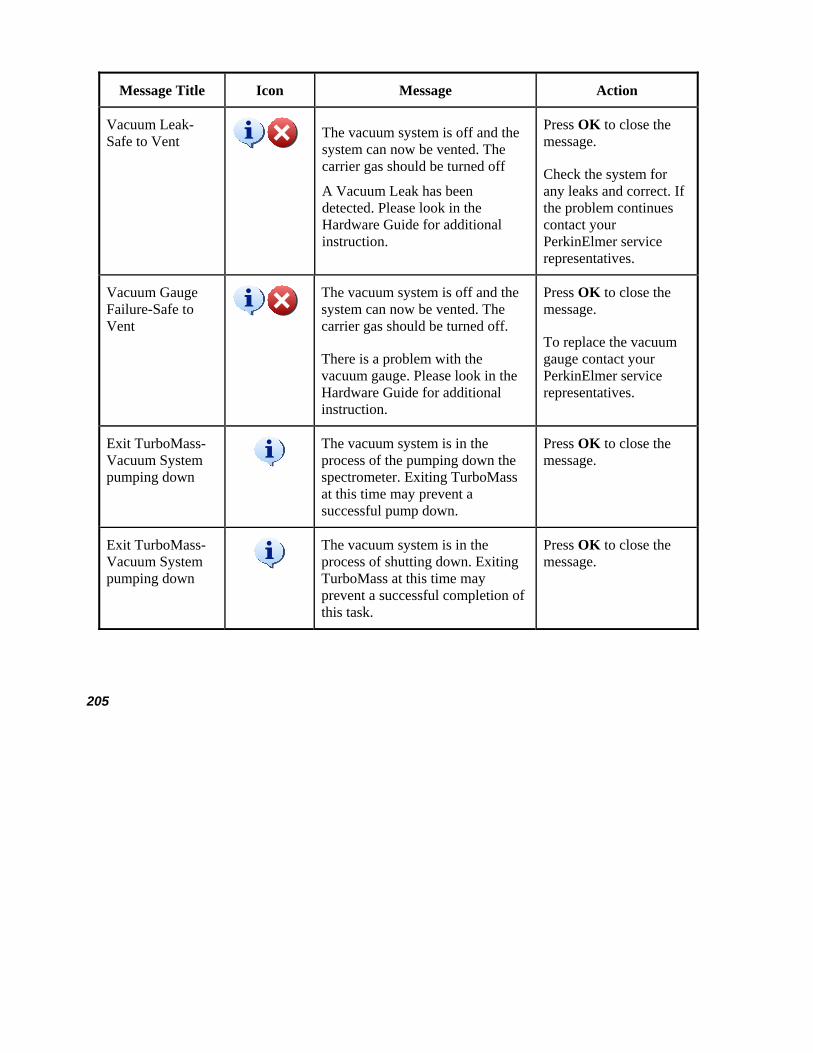
205
Message Title Icon Message Action
Vacuum Leak- Safe to Vent
The vacuum system is off and the system can now be vented. The carrier gas should be turned off
A Vacuum Leak has been detected. Please look in the Hardware Guide for additional instruction.
Press OK to close the message.
Check the system for any leaks and correct. If the problem continues contact your PerkinElmer service representatives.
Vacuum Gauge Failure-Safe to Vent
The vacuum system is off and the system can now be vented. The carrier gas should be turned off.
There is a problem with the vacuum gauge. Please look in the Hardware Guide for additional instruction.
Press OK to close the message.
To replace the vacuum gauge contact your PerkinElmer service representatives.
Exit TurboMass-Vacuum System pumping down
The vacuum system is in the process of the pumping down the spectrometer. Exiting TurboMass at this time may prevent a successful pump down.
Press OK to close the message.
Exit TurboMass-Vacuum System pumping down
The vacuum system is in the process of shutting down. Exiting TurboMass at this time may prevent a successful completion of this task.
Press OK to close the message.

Clarus 600 MS Hardware Guide
206
Message Title Icon Message Action
Backing Pump is on
The system is not in an operating state. A diffusion pump failure, a vacuum leak or a vacuum gauge failure could have occurred.
If the transfer line or the source temperatures are above 100C, please wait until they have cooled before pressing OK.
Pressing the OK button will turn off the backing pump.
If the transfer line or the source temperatures are above 100C, please wait until they have cooled before pressing OK.
Pressing the OK button will turn off the backing pump.
Problem with Vacuum
The backing pump could not reach the necessary vacuum level to start the diffusion pump. There could be a problem with a vacuum leak, the backing pump or the vacuum gauge.
The backing pump will be turned off. Make sure that the vent valve is closed before restarting the backing pump.
Press OK to close the message.

207
Replacement Parts
Contact PerkinElmer for Columns, Supplies, Accessories, and Replacement Parts.
Supplies, accessories and replacement parts can be ordered directly from PerkinElmer's catalog service. PerkinElmer offers a full selection of high-quality chromatography data handling products and gas chromatography supplies and columns through the Gas Chromatography Supplies Catalog and the Gas Chromatography Column Catalog.
To place an order for supplies and many replacement parts, request a free catalog, or ask for information:
Telephone:
• U.S. only: Call toll free 1-888-PE-CHROM, 8 a.m. to 8 p.m. EST. Your order will be shipped promptly, usually within 24 hours.
• Worldwide: Call your local PerkinElmer sales or service office or call PerkinElmer, Shelton, CT USA 1-203-925-4600.
Internet: http://www.perkinelmer.com
e-mail: [email protected]

Clarus 600 MS Hardware Guide
208

Index


Index
211
Index
A Aluminum oxide, 109, 116
C Caution, 9, 86 Changing a column, 88 Checklist
pre-installation, 39 pre-operational, 71
Chemicals definitions of warnings, 26 hazardous, 24
CI leak checking, 163 setting parameter values, 166 setting up, 165
CI Inner Source, 113 disassembling, 114 maintenance, 113 rinsing and reassembling, 116
Cleaning the Instrument, 21 Column, 70
leak checking, 99 selection, 70
Compressed gases, safety practices, 22 Computer requirements, 37
D Diffusion Pump, 61
pumping down, 64
E EI Inner Source, 106
cleaning, 109, 115 disassembling, 107 reassembling, 110 rinsing, 109
EI Inner Source maintenance, 106 EI to CI mode changing, 160 Electricity, safety practices, 20 Environmental requirements, 32
F Filament
replacing, 121
G Gases, 36
H Hardware
maintenance, 85 Heated surfaces, warnings, 23 Heaters
quad, replacing, 144 source, replacing, 142
I Inline Gas Purifiers, 159 Inner Source, 104
maintenance, 104 removing, 105
Introduction to TurboMass, 49 Ion optics assembly
removing, 129, 135 Ion source, 57
L Labels
WEEE Instructions, 30 Leak checking, 79
CI, 163

Clarus 600 MS Hardware Guide
212
M Maintenance, 75
cable removal, 135 cleaning the prequads, 138 EI inner source, 106 inner source, 104 leak-checking, 79 mass analyzer, 128 outer source
wire connections, 151 outer source, cleaning, 146 outer source, detail view, 149 overview, 75 PMT tube removal, 133 preparing for, 85 reassembling TurboMass, 152 removing the cover panels, 131 replacing an outer source themocouple, 139 replacing the quadrupole heater, 144 schedule, 77 source heaters, 142 tuning, 82 vacuum system, 154
oil, 154 venting the system, 87
Mass analyzer maintenance, 128
O Operating conditions, 27 Outer source
cleaning, 146 detail view, 149
Overview Clarus 600/560D GC, 51 ion source, 57 maintenance, 75 reference gas inlet, 54 troubleshooting, 177
P Photomultiplier Tube (PMT)
removing, 133 Pollution degree, 27
Power requirements, 33 Pre-installation checklist, 39 Pre-operational checklist, 71
R Reference Gas Inlet, 54 Refilling the reference gas vial, 100 Removing a column, 88 Removing the photomultiplier tube, 133
S Safety practices
ammonia gas, 24 compressed gases, 22 electricity, 20 environmental requirements, 32 general laboratory safety, 29 generic warnings, 18 heated zones, 23 hydrogen, methane, isobutane, 24 overview, 18 pollution degree, 27 requirements, 35 space, 31 storage, 28 ventilation, 23
Software, 68 top level screen, 68 Tune page, 69
Source, 119 reinstalling, 119
Space requirements, 31 Spare components, 178 Storage, 28 Supplies, accessories, replacement parts, 45 system requirements, 37
T Transfer line
cooling, 86 Traps
click on connectors, 159 replacement, 159
Index
213
Troubleshooting, 177 chart, 180 overview, 177 spare components, 178
Tune page, 69 Tuning, 82 TurboMass
system requirements, 37 TurboMass Software, 68 Turbomolcular Pump
venting, 64 Turbomolecular Pump, 61
V Vacuum Controls, 61
Vacuum Gauge, 67 Vacuum system, 59
options, 61 rotary pump, 59
Vacuum System diffusion pump, 61, 64 turbomolcular pump venting, 64 turbomolecular pump, 61
Ventilation, safety practices, 23 Venting, 87
W Warnings, 10, 18
hazardous chemicals, 26