clarkson college of technology synthesis of … · synthesis of stiffened shells of revolution...
TRANSCRIPT
Clarkson College of TechnologyPotsdam, New York 13676
SYNTHESIS OF STIFFENED SHELLS OF REVOLUTION
FINAL REPORT
(covering the period June 1969-May 1974)
NASA GRANT NGL 33-007-075 '
W.A. Thornton, Principal InvestigatorAssociate Professor of Civil and EnvironmentalEngineering
Submitted: 30 July 1974
C3
W1e D Ti-c
g632
1969 Oj~q10ahn3
https://ntrs.nasa.gov/search.jsp?R=19740021197 2018-07-08T03:24:13+00:00Z
2
±IAEUDING PAGE BLANKI NOT FLMED
SUMMARY
The,work done under this grant can be broken into three phases. A
description of these phases is given in Table 1. Additional comment on these
phases follows.
Phase I (1969-1971) Design of uniform shells (mainly cones) using a
membrane prebuckling analysis, the Langley developed SALORS program for2 3
general buckling, the Fiacco McCormick and Powell Penalty functions, and
Davidon Fletcher Powell4 and Marquardt's5 methods for function minimization.
Seven design variables were considered. All derivatives exact except general
buckling load derivative. This work was an extension of Morrow and Schmit's6
work. Work was published in Journal of Spacecraft and Rockets.7
Phase II (1971-1973) Design of completely nonuniform shells (cones, spheres,
toriodal segments) using a linear bending prebuckling analysis. The design
problem was formulated and solved as a control theory problem. A first order
differential equation formulation was used. General buckling was not included
in the design process but was checked after a design was obtained for local
yield and buckling constraints. A total of 245 design variables were used.
This work is described in the Ph.D. thesis of D.K. Majumder,8 a graduate
student supported by the grant.
Also during this period, difficulties with the SALORS problem were en-
countered and a new program, named SORAN (Shell of Revolution Analysis) and
based on Cohen's computer approach, was developed.
Phase III (1973-1974) The design process of Phase II was revised to reduce
the number of design variables to about 30 by considering piecewise uniform
designs. Also, the SORAN program was incorporated into the design scheme
so that general buckling could once again be considered in the design process.
A perturbation formula based on the SORAN program was derived and this allows
exact derivatives of the general buckling load to be computed with very little10
additional computer time. A paper which presents this formula has been
accepted for publication in the AIAA Journal.
In order to reduce the computer time required, a mixed interior-exterior
penalty function is used which allows a reduction in the number of times the
1<
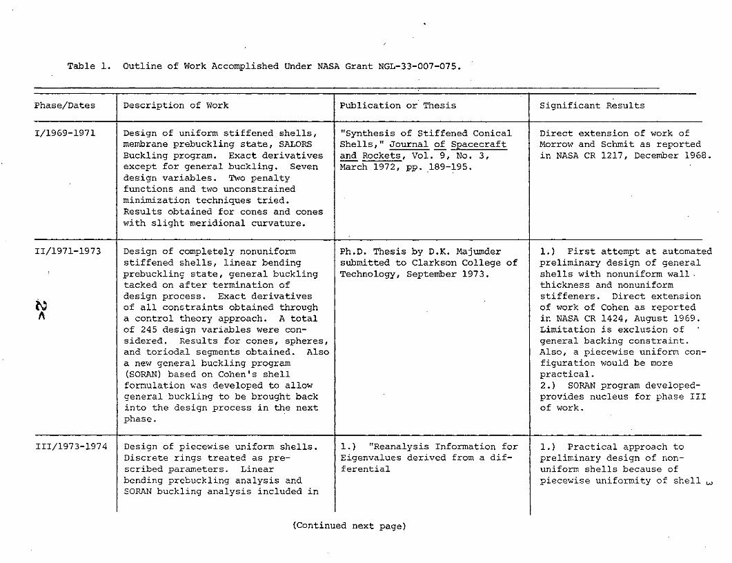
Table 1. Outline of Work Accomplished Under NASA Grant NGL-33-007-075.
Phase/Dates Description of Work Publication or Thesis Significant Results
1/1969-1971 Design of uniform stiffened shells, "Synthesis of Stiffened Conical Direct extension of work ofmembrane prebuckling state, SALORS Shells," Journal of Spacecraft Morrow and Schmit as reportedBuckling program. Exact derivatives and Rockets, Vol. 9, No. 3, in NASA CR 1217, December 1968.except for general buckling. Seven March 1972, pp. 189-195.design variables. Two penaltyfunctions and two unconstrainedminimization techniques tried.Results obtained for cones and coneswith slight meridional curvature.
II/1971-1973 Design of completely nonuniform Ph.D. Thesis by D.K. Majumder 1.) First attempt at automatedstiffened shells, linear bending submitted to Clarkson College of preliminary design of generalprebuckling state, general buckling Technology, September 1973. shells with nonuniform wall.tacked on after termination of thickness and nonuniformdesign process. Exact derivatives stiffeners. Direct extensionof all constraints obtained through of work of Cohen as reported
A a control theory approach. A total in NASA CR 1424, August 1969.of 245 design variables were con- Limitation is exclusion ofsidered. Results for cones, spheres, general backing constraint.and toriodal segments obtained. Also Also, a piecewise uniform con-a new general buckling program figuration would be more(SORAN) based on Cohen's shell practical.formulation was developed to allow 2.) SORAN program developed-general buckling to be brought back provides nucleus for phase IIIinto the design process in the next of work.phase.
III/1973-1974 Design of piecewise uniform shells. 1.) "Reanalysis Information for 1.) Practical approach toDiscrete rings treated as pre- Eigenvalues derived from a dif- preliminary design of non-scribed parameters. Linear ferential uniform shells because ofbending prebuckling analysis and piecewise uniformity of shell ,SORAN buckling analysis included in
(Continued next page)

Table 1 (Continued)
design formulation. Exact derivatives Equation Analysis Formulation," which should allow easyof all constraints included (for the accepted for publication in the fabrication.general buckling load this required AIAA Journal. 2.) Self Adjoint formulationthe derivation of a new formula for 2.) "Optimal Stiffened Shells of SORAN buckling programeigenvalue perturbations.). A of Revolution," to be sub- allows efficient calculationtotal of 30 design variables are mitted for possible publication of derivatives of generalconsidered. A mixed interior-ex- (see Appendix this report). buckling load.terior penalty function is used in con- 3.) Perturbation formula forjunction with the Fletcher-Reeves buckling loads of a generalmethod. shell of revolution derived.
4.) The Phase III designcapability is probably themost general preliminary staticdesign capability presentlyavailable for shells of re-volution.
A
5
general buckling load must be computed. Also, this latest approach allows
discrete-rings to be included in the design process as prescribed parameters.
A paper describing this latest design approach has been written (see Appendix)
and will be submitted for publication shortly. The capability presented in
this paper is felt by the principal investigator to be the most general
preliminary shell of revolution static design capability presently available.
Detailed Description of Work Done
A total of ten Status Reports have been submitted during the course of
the grant. These give the detailed description of the work done. The work
done during the final report period (Dec. 1973 to May 1974) is contained in
the Appendix to this Final Report in the fbrm of a paper to be submitted for
publication.- This paper and the others noted in Table 1 will complete the
dissemination in the open literature of the work described in the various
Status Reports.
General Discussion
Goal of Research - Limitations - Art of Design
The goal of this research was to attempt the automation of the design
process for general stiffened shells of revolution. In the context of pre-
liminary design of parts of a complex shell structure such as a missile (S4-B
etc.), this goal has been accomplished.' Two qualifying words (preliminary and
parts) need further clarification.
By "preliminary" design a preliminary sizing of the elements of the
shell by means of relatively crude design formulas is meant. For a
stiffened shell, this usually means computing the general buckling load
with"smeared" stiffeners (the equivalent shell is an orthotropic monocoque
shell) and treating the failure modes of the stiffeners themselves and the
shell wall between stiffeners as independent (or uncoupled).
By "parts" of a shell a distinction is made between the shell structure
which generally will be fabricated of several shells joined together by
discrete stiffeneing rings and the "part" of the shell structure between-
4<
6
these discrete rings.
In the ,design of any shell structure composed of several parts which
are connected by stiffening rings, these rings must of course also be
designed. At the present state of the art, it is felt that the design of
these rings is best left to the experienced designer. With the preliminary
designs for the parts of the shell obtained from the capability developed under
this Grant, and an advanced computer capability (such as NASTRAN or the
program developed by Bushnell1 1 for handling branched shells), the experienced
designer can reliably size the stiffening ring (or rings) and make whatever
modifications are necessary in the preliminary designs of the shell parts to
arrive at a final design.
There are two reasons why it is felt that the final design including
connections is best done manually at present.
I.) There is quite a bit of art involved in the design process. It is
one thing to automate the design of parts of a structure and quite another to
automate the design of a structure as a whole. As an example of the kind of
thing involved here, consider the approach to design of the stiffening ring12
used in Cohen's NASA CR 1424. (Aug. 1969). Here, the stiffening ring at the
base of the shell is sized to suppress the n =2 shell buckling mode. This
allows the design of the shell to be uncoupled from the design of the
stiffening ring. While the entire shell (shell plus end rings) could be designed
by an automated process, it seems clear that Cohen's approach is the superior
one.
2.) If all the art involved in design were able to be quantified into
a computer automated design approach, the only way a final design could be
obtained directly would be by incorporating such programs as Bushnell's
branched shell analysis into the design process. Considering the core and
run time necessary for such programs, this seems prohibitively expensive at
the present time.
5<

7
Analysis Methods for Design
13It has been noted by Storaasli and Sobieszczanski that a need exists
for analysis techniques which are developed with an eye on their use in
design. The basic idea here is to develop analysis techniques which do not
require complete re-solution when small changes are made in parameters
which govern the results obtained from the analysis. Then, using, for in-
stance, a Taylor series expansion in the design variables about the initial
design point, analyses for neighboring points can be determined without re-
solving the problem if the derivatives are available from the first solution.
In buckling problems, symmetry and self-adjointness are properties of the
formulation which are central to efficient re-analysis, since in this case
the required derivatives can be calculated-without re-analyzing the problem.
Since -the SALORS program is not a symmetric-formulation, it is difficult to
use in a redesign environment. This prompted the development at Clarkson of
the SORAN program which has the self-adjoint property. Basically, the difficulty
with nonsymmetric or nonself adjoint formulations is that either the adjoint
eigenvalue problem must be solved or the derivatives of the eigenvectors must
be found in order to get the derivatives of the eigenvalues. If the adjoint
problem is solved, generally its solution is just as costly as the solution
to the original eigenvalue problem, thereby greatly degrading the efficiency
of the design program.
The design programs developed during Phase III of this Grant (Table 1)
are based on self-adjoint prebuckling and buckling analyses and this property is
exploited to create an efficient redesign process. The prebuckling and buckling
formulations are both formulated as sets of first order ordinary differential
equations. These equations are integrated by the fourth order Runga Kutta1
method and the integration method of Anderson, et al. For the design of piece-
wise uniform shells, this first order formulation has the following ad-
vantages over the second order approach of SALORS:
1.) The shell must be segmented to provide for an accurate solution. This
segmentation allows for an obvious piecewise uniform shell. The SALORS
approach requires no segmentation and thus an artificial segmentation must
be introduced to provide for piecewise uniformity of the shell.
2.) The first order formulation requires no derivatives of design variables

8
with respect to meridional position whereas SALORS does. At points of
segmentation these derivatives do not exist. Hence, in SALORS, some
special steps must be taken to compute these derivatives on either side of
the segmentation point.
Optimality Criterion for Design
The design method developed under this grant uses the versatile
math programming techniques and thus is guaranteed to converge to at least
a local minimum. During the last few months of the grant, an optimality
criterion approach based on a variable energy method,1 4 which was developed
at Clarkson for use in frame and curved beam design, has been applied to
shell design. Excellent results were obtained for a monocoque cone. Considering
6 segments and stress and general buckling constraints, a minimum weight design
was obtained with only 8 reanalyses and no derivative calculations. This can
be contrasted with about 90 reanalyses (about 30 of which also require
derivative calculations) which would be required for the math programming method.
At present the energy ratio method is limited to one design variable per
segment. That is why a monocoque shell was studied. For the stiffened shell,
there are 5 design variables per segment. For the energy approach to be applied
to these shells either 4 relationships must be introduced to reduce the 5
design variables to 1 or some more general energy approach must be taken.
Some preliminary studies considering the energy in the wall as a whole as
opposed to the separate energies of the parts of the wall (skin, rings,
stringers) have been made but no general results have been obtained and no
conclusions can be made at present about this approach. The great potential
reduction in reanalyses (90 to 8) required for an optimal design should
provide the impetus to explore further an energy based optimality criterion
method for stiffened shell design.
7<
9
Directions for Further Research
1.) The probuckling and buckling analyses have been formulated and utilized
within the design process in a very efficient manner. The math programming
method used could be improved. The method of Schmit and Farshi 5 using "hyper-
circles" appears promising in this respect. Alternately, an energy based
optimality criterion method for multiple design variables per segment
should be developed. Preliminary results (as noted in the preceding section
of this report) indicate that a method of this kind would greatly reduce
the number of reanalyses required for an optimal design.
2.) If an optimality criterion method proves feasible for this problem, the
number of reanalyses required for an optimal design can be expected to be
reduced by a factor of about 10. With this kind of reduction, it begins to
become feasible to consider incorporating a shell analysis using discrete
rather than smeared rings into the design process. This would give a more
accurate accessment of local ring buckling (stringers would still be "smeared"),
skin yielding and skin buckling. The resulting designs would still be
preliminary designs because the connections of the shell (or shell part) to
its environment would very likely still be considered manually by the
designer.
10
References
1. Anderson, M.S., Fultion, R.E., Heard, W.L. Jr., and Walz, J.E., "Stress
Buckling, and Vibration Analysis of Shells of Revolution," Computers and
Structures, Vol. 1i, 1971, pp. 157-192.
2. Fiacco, A.V., and McCormick, G.P., Nonlinear Programming: Sequential
Unconstrained Minimization Techniques, Wiley, New York, 1968, pp. 39-71.
3. Fletcher, R., ed., Optimization, Academic Press, New York, 1969, pp.
283-298.
4. Fletcher, R. and Powell, J.J.D., "A Rapidly Convergent Descent Method for
Minimization,". The Computer Journal, Vol. 6, No. 2, 1962, pp. 163-168.
5. Marquardt, D.W., "An Algorithm for Least Squares Estimation of Nonlinear
Parameters," Journal of the Society for Industrial and Applied Mathematics,
Vol. 11, No. 2, 1963, pp. 431-441.
6. Morrow, W., and Schmit, L.A., "Structural Synthesis of a Stiffened
Cylinder," NASA CR 1217, 1968.
7. Thornton, W.A., "Synthesis of Stiffened Conical Shells," Journal of
Spacecraft and Rockets, Vol. 9, No. 3, March 1972, pp. 182-195.
8. Majumder, D.K., "Minimum Weight Design of Stiffened Shells of Revolution,"
Ph.D. Thesis, Clarkson College of Technology, Sept. 1973.
9. Cohen, G.A., "Computer Analysis of Asymmetric Buckling of Ring Stiffened
Orthotropic Shells of Revolution," AIAA Journal, Vol. 6, No. 1, Jan. 1968,
pp. 141-149.
10. Thornton, W.A., and Majumder, D.K., "Reanalysis Information for Eigen-
values Derived from a Differential Equation Analysis Formulation," AIAA
Journal (accepted for publication).
11. Bushnell, D., "Stress, Stability, and Vibration of Complex Branched
Shells'of Revolution," presented as paper 73-360 at the 14th AIAA/ASME/SAE
Structures, Structural Dynamics, and Materials Conference, Williamsburg,
Va., March 1973.
12. Cohen, G.A., "Structural Optimization of Sandwich and Ring-Stiffened
120 Degree Conical Shells Subjected to External Pressure," NASA CR 1424,
August 1969.
13. Storaasli, 0.0., and Sobieszczanski, J., "On the Accuracy of the Taylor
Approximation for Structure Resizing," AIAA Journal, Vol. 12, No. 2,
Feb. 1974, pp. 231-232.
14. Gorzynski, J.W., and Thornton, W.A., "A Variable Energy Ratio Method
for Structural Design," Journal of the Structural Division, ASCE, accepted
for publication.
15. Schmit, L.A., and Farshi, B., "Some Approximation Concepts for Structural
Synthesis," AIAA Journal, Vol. 12, No. 5, May 1974, pp. 692-699.
10<
Appendix
Contains a paper which will be submitted for possible publication.
This paper contains the work done during the last report period,
Dec. 1973 - May 1974.
11L<

Optimal Stiffened Shells of Revolution1
D.K. Majumder 2 and W.A. Thornton3
Department of Civil and Environmental EngineeringClarkson College of TechnologyPotsdam, New York 13676
Summary
A method to produce piecewise uniform optimal stiffened shells of
revolution is presented. The method uses a first order differential
equation formulation for the shell prebuckling and buckling analyses and
the necessary conditions for optimality are derived by a variational ap-
proach. A variety of local yielding and buckling constraints and the general
buckling constraint are included in the design process. The local constraints
are treated by means of an interior penalty function and the general buckling
load is treated by means of an exterior penalty function. This allows the
general buckling constraint to be included in the design process only when it
is violated. The self adjoint nature of the prebuckling and buckling
formulations is used to reduce the computational effort. Results for four conical
shells and one spherical shell are given.
1. This work was supported by the National Aeronautics and Space Administrationunder Grant NGL 33-007-075
2. Research Associate; presently Structural Engineer, Reutter Assoc., Camden,New Jersey.
3. Associate Professor of Civil Engineering; on leave 1974-1975 as Directorof Engineering, Cives Corp., Syracuse, New York.
i12<

2
Introduction
Several papers have dealt with the problem of optimal shell design.(1) (2) (3)
Among these are papers by Salama and Ross , Cohen and Thornton
Salama and Ross (1 ) consider nonuniform unstiffened shells for stress and
natural frequency constraints. They use a finite element computer program
for the analysis and couple this with two alternative mathematical programming
techniques. Only one load condition is considered, but the generality of the
approach is such that multiple load conditions could easily be considered.
Cohen (2 ) considered stiffened conical shells for local and general buckling
constraints. One load condition, uniform-external pressure is considered.
A membrane prebuckling state is used for all local constraints. An empirical
correlation formula is used to include the general buckling load in the design
process. A simultaneous failure mode design technique is used. The wall
thickness is uniform and nonuniform ring size and spacing are included.
Stringers are not designed. Thornton (3 ) has treated conical ring and stringer
stiffened shells. Local stress and buckling constraints and general buckling
are included, the latter by means of a general shell of revolution buckling
analysis, the SALORS (4 ) program. The local constraints are based on a membrane
prebuckling state. The wall thickness is uniform, as is the ring and stringer
size and spacing. The design process uses a mathematical programming technique.
Results for one load condition, uniform external pressure, .are presented, but
the generality of the approach permits the inclusion of multiple load conditions.
This paper sketches an approach to shell design which is felt to be an
extension of the approaches used in the above papers, because: 1. linear
bending shell theory is used for the prebuckling analysis and all local constraints,
2. the shell wall thickness, the stiffener size parameters, and the stiffener
spacings, are treated as piecewise uniform functions of meridional position,
3. the general buckling load is used as a constraint only when it plays an
active role in the design, and 4. results for conical and spherical shells
have been obtained.
.13<

3
Structural Analysis
'The piebuckling behavior of the shell is assumed axisymmetric. In
this case, the prebuckling equations can be written as six first-order
ordinary differential equations as
ry' + ay - bz = p(1)
rz' - cy + dz = 0
where the prime denotes differentiation with respect to meridional position,T
s, y is a vector of meridional forces, y = LP, Q, M,_ , z is a vector of
meridional displacements, zT=1 ,,Xj , r defines meridional position, p is a
vector of loads per unit area, p = X1,X,LJ , and a, b, c, and d are
matrices which satisfy the self adjointness-conditions
T T Ta+d =r'I, b = b , c = c (2)
The notations for y, z, and p are from Ref. 5, and the coefficient matrices
a, b, c, and d can be obtained indirectly from Ref. 5.
The general buckling analysis can be formulated as eight first order
ordinary differential equations as
rY' + AY - BZ - X F = -paY - pZ + pFe
(3)
rZ' - CY + DZ = -j'Z
where the notation of Eqs. 6 of Ref. 6 is followed except that upper case
Y and Z are used here to distinguish the eigenvector of meridional forces
and displacements from the prebuckling forces and displacements. The
coefficient matrices a and 8 can be found in Ref. 6 and the matrices A, B,
and C can be found in Ref. 7 (denoted a, b, c there). Also, F is a vector
of perturbation forces, he is a reference buckling load and p is the buckling
load. The matrices A, B, C, D, a, 3, and 6 satisfy the self adjointness
conditions as
14<

4
T T T - -T - -TA + D = r'I, B B, C = C , + = 0, =T (4)
Eqs. 1 and Eqs. 3 are solved by the integration method of Appendix A of
Ref. 4. In order to provide for an accurate solution to these equations,
the shell must usually be segmented meridionally. Also, if concentrated
loadings or discrete rings are present, the shell must be segmented to
accommodate these loads or rings. The conditions that must be satisfied
by the prebuckling equations at points of segmentation are
ray - kz = L, s = s. (5)
where s. denotes the points of meridional segmentation, L is a matrix of
applied loads and k is the discrete ring stiffness matrix which can be found
in Ref. 7. The notation Ay is as defined by Eq. 11 of Ref. 7. The matrix
k is symmetric and this symmetry is necessary for a self adjoint formulation.
Conditions at the top and bottom of the shell are a special case of Eq. 5
and classical supports can also be considered by replacing Eq. 5 by the
appropriate classical condition, i.e., hinge, roller, fixed, etc. The
only requirement on the end conditions is that they result in a self
adjoint formulation.
At points of segmentation, the buckling analysis must satisfy the con-
ditions
rAY -KZ=KZ = -KZ = s. (6)
where K is given by Ref. 7 and K can be found in Ref. 6. Both K and K
are symmetric (which property is necessary for self adjointness). As in
the case of the prebuckling analysis, classical conditions at the ends
can also be considered but here again it is important that these classical
conditions provide a self adjoint formulation. The reason for this will be
seen later.
When the prebuckling and buckling equations have been solved, the
response of a particular shell design is available and the adequacy of this
design can be determined. The adequacy of a design is judged with respect
15<
5
to constraints on the response of the design. If the response does not
violate the constraints, the design is acceptable, otherwise not. Defining
the "response ratio" 0~ = (stress in wall)/(yield stress), if 0 1 i, the
design is acceptable with respect to wall stress. Other constraints can be
put in the same form and if 0i. 1 for all i the design is acceptable. The1
constraints considered in this paper are 1) skin yield, 2) stringer yield,
3) ring yield, 4) skin buckling, 5) circumferential panel buckling, 6) meri-
dional panel buckling, 7) normal displacement, 8) meridional rotation (X),
and 9) -general buckling. Minimum gage and fabricational constraints are
also included. Discussions on constraints 1, 2, 3, 4, 5, and 9 are contained
in Ref. 3. Normal displacement(6) and meridional rotation (7) are self ex-
planatory. Meridional panel buckling (8) considers the situation that would
exist if the shell were to be stiffened with stringers but no rings. The
meridional panel is a panel imagined to exist at each meridional position which
is of infinite length in the meridional direction and has a width equal to the
stringer spacing at the point under consideration. This constraint complements
the circumferential panel buckling constraint (called panel buckling in Ref. 3)
because circumferential panel buckling handles the case where only rings
stiffen the shell.
Local buckling of the stiffeners is not considered as a constraint.
Rather, each stiffener is proportioned to force stiffener yielding and buckling
to occur simultaneously, thus reducing the number of design variables.
Structural Design
Once a particular design has been judged acceptable (it is assumed that
at least one such design can be found) the problem becomes one of determining
whether or not this particular design is the best obtainable. The best (or
optimal) design will here be considered to be the one which weighs the least.m
The weight of the shell is given by W = E I Wk ds where m is thek=l k
number of segments into which the shell is partitioned and
16<4:
6
AAR ASK K
Wk= 2n W tW r + 2rrR S r + 2nS rK S (7)
K RK Sk
In Eq. 7, y = weight density, t = wall thickness, A = stiffener area, S
stiffener spacing, subscript W refers to the wall, subscript R refers to the
rings and subscript S refers to the stringers. Also, Ik is the length of the
kth segment and rk is the radius of the shell at the beginning of the kth
segment. The stringer spacing S is defined at the beginning of the kthk
segment. The areas AR and AS are functions of the shape of the rings and
stringers. For circular rings of thickness tR and diameter DR , AR = T tRDRFor Zee rings of flange width/web height ratio of 2/5, thickness t and
web height DR , AR = 1.8 tRDR . Thus in general
A = A(t,D) (8)
The quantities t , ts , tR , Ds , DR , Ss, and SR , which in general are
different in each segment k of the shell, are called the design variables.
In order to reduce the number of design variables, the stiffeners are
assumed to yield and buckle locally simultaneously. Thus, for circular8
stiffeners, the buckling stress aB is equated to the yield stress a ,y
B = .4E t/D = 0 (9)B Y
which yields
t = (a y/.4E) D (10)
For Zee stiffeners2
B = 3.35E ( 2 = y (11)B D y
which yields
t = (a y/3.35E)1/2D (12)

7
and other formulas can be derived for other stiffener shapes. In Eqs.
9-12, E.isYoung's modulus.
With the stiffener thicknesses eliminated through Eqs. 10 and 12, the
design variables reduce to t , D, DR , S and S . These five are collectedw s s Rinto a vector u in the above order.
A concise statement of the design problem can now be given as; find
u = u such that W(u ) * min while i(u ).5 1, all i. This design problem
can be formulated in the following way. Introduce a new notation for the
constraints as fi = l- i so that an acceptable design is one for which
f. z 0. Let all constraints except the general buckling constraint have1
indices which are members of a set I while the general buckling constraint
has an index which is the (sole) member of a set 0. Now define a function
Pk where
P = W + P + - i H.(f ) f 2 (13)k k f P i 1 k. k. i
1
In Eq. 13, p is a parameter which approaches zero sequentially and H is the
Heaviside function, H. = 0 when fk. 0 and-H. = i when fk. < 0. Combining
the function Pk with the prebuckling equations using Lagrange multipliers y
and z gives
J = S [Pk + z (ry' + ay - bz - p) -y (rz' - cy + dz)] ds (14)k k
The design problem can be stated in terms of J as; find u = u such that
J(u , y, z, y, z, , p) - min for a monotone decreasing sequence of values of
p. This is effectively a continuous form of the well known Fiacco-McCormick
penalty function method. The necessary conditions for a stationary value of J
in Eq. 14 are obtained by taking the variations of J with respect to
u, y, z, y, and z and setting 6J =0. The variations in y and z result in
the reappearance of the prebuckling equations, the variations and y and z give
the adjoint equations, and the variation in u gives the gradient of J which
18<

must vanish for 6J = 0. Thus, the necessary conditions are, for 6z and
6y
ry' + ay - bz = p
(15)
rz' - cy + dz = 0
and for 6Y and 6z
T
ry' + ay - bz = - (- )az
(16)T
rz' - cy + dz = - (a).
while for 6u
ap ap=k S Pk -T 6a -T ab
k k auk yp auk z k z auk
(17)
-T 6c -T ad-y Y + y zds 0
uk auk
Eq. 17 is a shorthand notation. Writing Eq. 17 out for the jth element of ukgives
G. p - k P + 6au Uj yq + ....] ds (18)j k k a k pq p ujk
Regarding Eqs. 15 and 16 it will be noted that they are formally self
adjoint (they are not completely self adjoint because the right hand sides
differ). Since the boundary and intermediate conditions for Eqs. 15 (the
prebuckling equations) produce a self adjoint formulation and are uneffected
by the :terms on the right hand side of Eqs. 16, the boundary and intermediate
conditions are the same for Eqs. 15 and Eqs. 16. This is important because
it allows the 3 complementary solutions to Eqs. 15 obtained by the method of
Appendix A of Ref. 4 to be used as the 3 complementary solutions for Eqs. 16.
Thus, only one new particular solution must be obtained to solve Eqs. 16
once Eqs. 15 have been solved. <
9
It will be noted that no explicit use of the buckling solution given
by Eqs. 3 and 5 has appeared in this section of the paper except for the
appearance of p in the constraint f , ieO and the derivatives a~/au k in
Eq. 17 (and Eq. 18). Eqs. 3 and 5 must be solved to provide p for f.,
icO to allow evaluation of Pk in Eq. 13. The terms p/6uk are obtained from
Ref. 10. For the jth design variable and for the assumed critical pth
buckling mode,
eT SA T aB T aC T2 2 Y -Z Z + Y -Y ]ds +p j [2Z Y
ujk ak P ujk ujk j Ak p aujk
'-Z T Z ds T K T K Z/S jk s. jk s. p Ujk
i 1
T- T T T(-2Z aY - Z pZ +F Z pds + Z ZpJ (19)P P P P P s.P
The derivation of this formula depends on the self adjointness of the buckling
formulation.
All of the derivatives in Eq. 17 (Eq. 18) can now be computed in closed
form. Eq. 17 is used as the gradient for the Fletcher-Reeves method(1 1 )
that is used to solve the sequence of unconstrained minimization problems
which result from the introduction of the penalty function. The Fletcher-
Reeves method was used in preference to the Davidon Fletcher Powell method
because it uses less core and core was at a premium in the computer used
(IBM 360/44). Of course, peripheral storage could be used and would most
likely result in improved run times.
One final point to be noted about the derivatives given by Eq. 19
is that the matrices a and are functions of u directly and also implicitly
through dependence on the prebuckling solution y and z. This latter dependence
is neglected in computing ap/bu with no noticeable effect on the results.
20<

10
Results
'The shell design method outlined in the foregoing sections has been
used to obtain designs for a number of stiffened shells. All shells studied
were broken into six segments and 11 finite difference stations were used
per segment. The size of the computer used (IBM 360/44) dictated these
numbers. Also, because this computer carries only about six significant
figures and truncates rather than rounds, double precision was required
to obtain reliable results for the general buckling calculation.
The manner in which the penalty function given by Eq. 13 was used varied
depending on the problem. In some cases, the general buckling constraint was
completely ignored until convergence was obtained for the constraints depending
on the prebuckling analysis. Then if general buckling was violated, the pro-
gram was run further until this violation was eliminated. In other cases,
general buckling was checked in the beginning and at each change in the p
parameter. It is not possible to give one way which is best for all cases.
The designer is free to choose his own variation in approach.
Each shell studied was broken into six segments as mentioned before.
Since there are five design variables per segment each shell design involves
a total of 30 design variables (25 when stringers are prescribed to be con-
tinuous from top to bottom of the shell). Considering the complexity of
the analysis for this problem, 30 is a sizeable number of design variables.
It will be recalled that the Fletcher Reeves (as with the Fletcher Powell)
method requires a one dimensional search to be performed for each search
direction computed and that for a convex function of n variables, in general n
one dimensional searches will be required for convergence. In the present
problem n = 30 and the function to be minimized is not necessarily convex
which means that generally more than 30 one dimensional searches will be
required for convergence. Assuming for the sake of argument that 30 one
dimensional searches lead to convergence, that each one dimensional search
requires approximately 3 function evaluations, and that convergence is required
for a sequence of at least 5 values of p, it can be seen that something on the
order of 450 function evaluations will be required to complete a design. It
should now be clear why 30 is considered to be a sizeable number of design
21<
variables for a problem of this complexity.
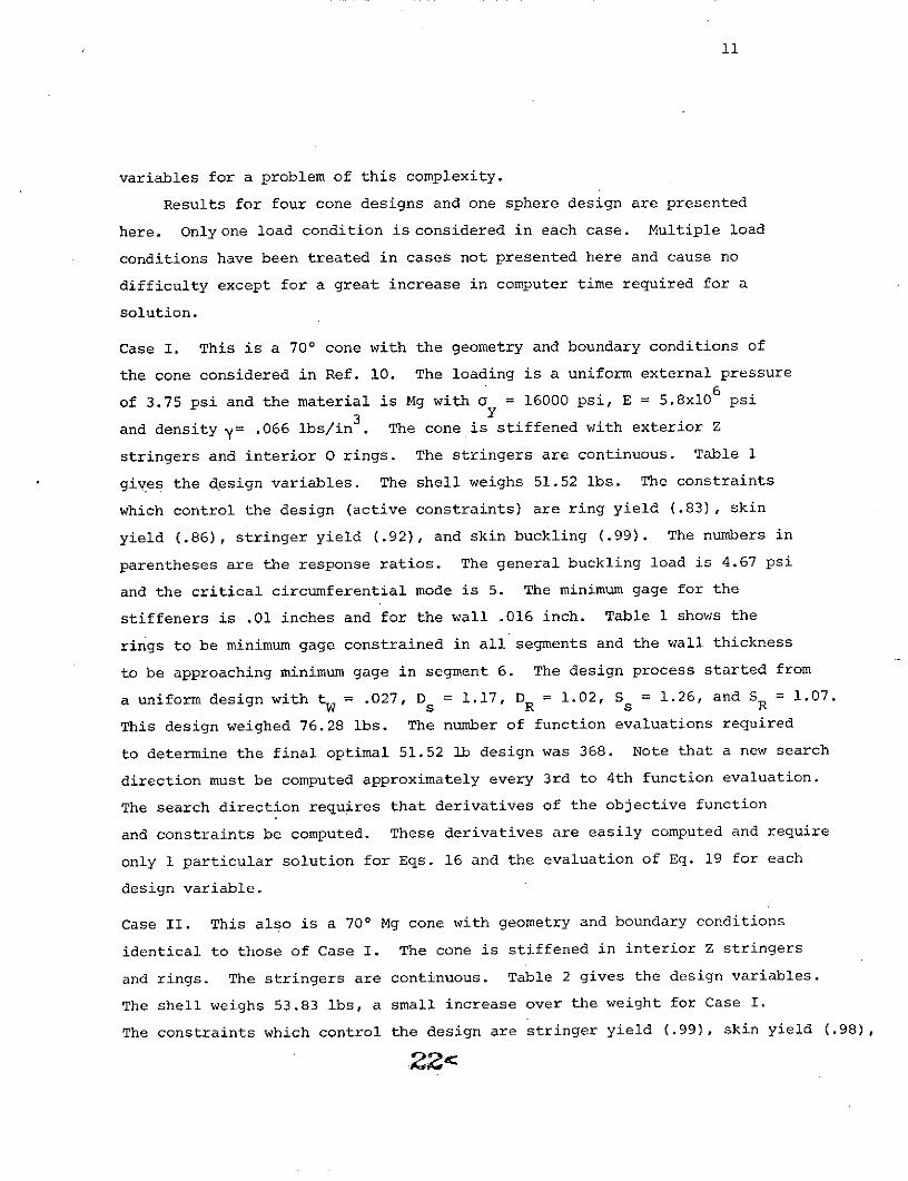
Results for four cone designs and one sphere design are presented
here. Onlyone load condition is considered in each case. Multiple load
conditions have been treated in cases not presented here and cause no
difficulty except for a great increase in computer time required for a
solution.
Case I. This is a 700 cone with the geometry and boundary conditions of
the cone considered in Ref. 10. The loading is a uniform external pressure6
of 3.75 psi and the material is Mg with a = 16000 psi, E = 5.8xl06 psi3y
and density y= .066 lbs/in . The cone is stiffened with exterior Z
stringers and interior 0 rings. The stringers are continuous. Table 1
gives the design variables. The shell weighs 51.52 lbs. The constraints
which control the design (active constraints) are ring yield (.83), skin
yield (.86), stringer yield (.92), and skin buckling (.99). The numbers in
parentheses are the response ratios. The general buckling load is 4.67 psi
and the critical circumferential mode is 5. The minimum gage for the
stiffeners is .01 inches and for the wall .016 inch. Table 1 shows the
rings to be minimum gage constrained in all segments and the wall thickness
to be approaching minimum gage in segment 6. The design process started from
a uniform design with tW = .027, Ds = 1.17, DR = 1.02, Ss = 1.26, and SR = 1.07.
This design weighed 76.28 lbs. The number of function evaluations required
to determine the final optimal 51.52 lb design was 368. Note that a new search
direction must be computed approximately every 3rd to 4th function evaluation.
The search direction requires that derivatives of the objective function
and constraints be computed. These derivatives are easily computed and require
only 1 particular solution for Eqs. 16 and the evaluation of Eq. 19 for each
design variable.
Case II. This also is a 700 Mg cone with geometry and boundary conditions
identical to those of Case I. The cone is stiffened in interior Z stringers
and rings. The stringers are continuous. Table 2 gives the design variables.
The shell weighs 53.83 lbs, a small increase over the weight for Case I.
The constraints which control the design are stringer yield (.99), skin yield (.98),
22"~dC

12
and skin buckling (.99). The general buckling load is 5.21 psi in mode number
6. No minimum gage constraints are active. The design process started with
the same uniform design as that used for Case I (which in this case weighs
93.0 lbs because of the use of Z rings). Convergence to the optimal 53.83
lb design required 250 function evaluations.
Case III. This again is a 700 cone with geometry and boundary conditions as
in Case I and II. The.stiffeners are internal Z stringers and rings, and
the stringers are here taken to be discontinuous (stringer spacing at the
beginning of any segment is independent of the stringer spacing at the
beginning of each other segment - this gives a total of 30 design variables).
The design process started with the same design variable values as in Cases
I and II but because of the stiffener change, this design now weighs 107.14 lbs.
Table 3 gives the design variables of the final optimal design which weighs
57.58 lbs. This weight represents a 7% increase over the weight of Case II.
The constraints which control the design are stringer yield (.97), wall
buckling (.99), and general buckling (.97). The general buckling load is
3.85 psi with mode 6. No minimum gage constraints are active. Convergence
to the optimal design required 454 function evaluations.
It was noted above that this design weighs 7% more than
the design of Case II. Since the stringers are free to take the best
spacing value in each segment, it was expected that the weight for this
case would be less than the weight for Case II rather than more. It is
expected that the use of more stringent convergence criteria would force
the weight of this case to less than that of Case II.
Case IV. As in Cases I, II, and III, this shell is a 700 Mg cone again
with the geometry and boundary conditions of Ref. 11. The stiffeners are the
same as those of Case I. The loading is a line load of 147.66 lb/in applied
at the center of the meridian (this is the segmentation point between
segments 3 and 4). The load of 147.66 lb/in was chosen so that the total
load applied to the shell is the same as the total for the 3.75 psi uniform
load. The design process started with a uniform design with tW = 0.8, Ds = 1.75,
D = 1.75, S = 2.0, which weighed 134.66 lbs. Table 4 gives the designs s
variables of the final optimal design which weighs 71.77 lbs. The constraints

13
that control the design are ring yield (.99), stringer yield (.99), skin yield
(.99), and wall buckling (.98). The general buckling load is 263.88 lbs/in
with mode number 7. Table 4 shows that the rings are minimum gage constrained
in all segments and the wall thickness is approaching minimum gage (.016) in
segment 6. The significant weight difference between this case and Case I
clearly shows the effect of differing load application. Convergence to the
optimal 71.77 lb design required 350 function evaluations.
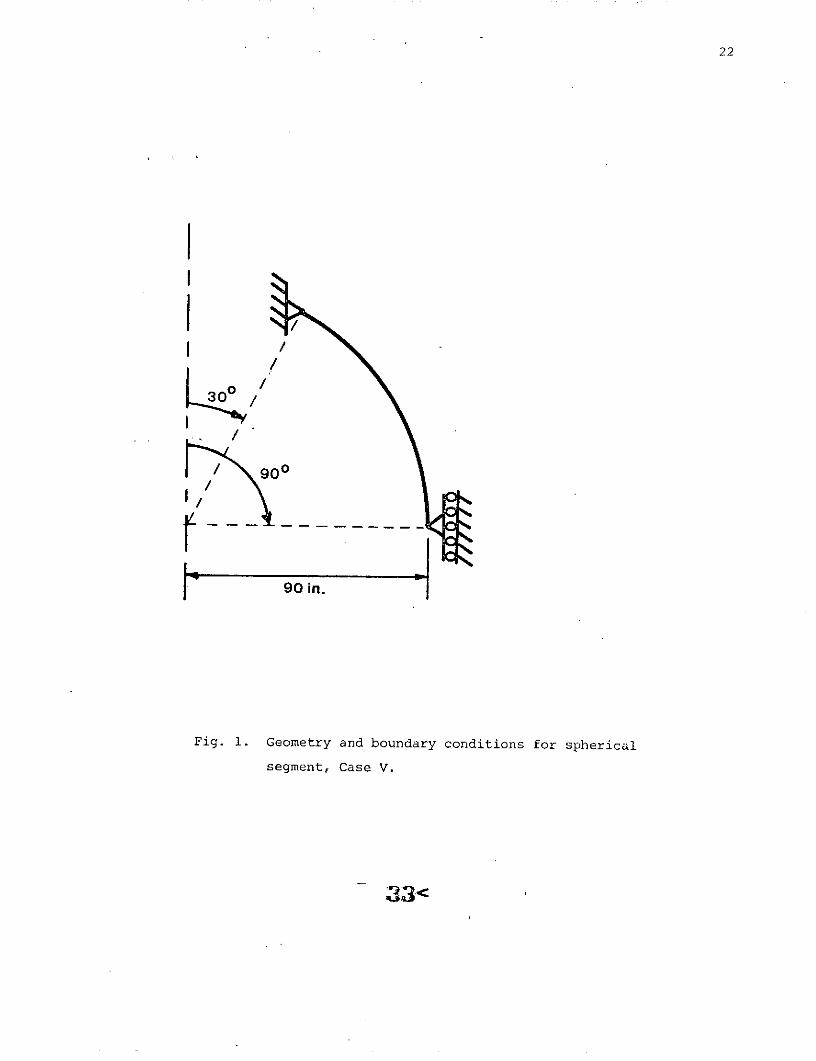
Case V. This is a segment of a spherical shell as shown in Fig. 1. The shell is
stiffened with exterior Z stringers and interior Z rings. The material is
6 3aluminum with a y = 40,000 psi, E = 10x10 psi, and density y = .1 lbs/in 3
The shell is loaded with a uniform external pressure of 10 psi. The stringers
are continuous. The design process started with a uniform design with
t = .6, D = .75; D = .75, S = 2.0, S = 2.0, which weighed 380.4 lbs.W - s- R s RTable 5 gives the design variables of the final optimal design which weighs
289.91 lbs. The constraints that control the design are ring yield (.89),
skin yield (.99), and wall buckling (1.0). The general buckling load is
22.75 psi and the critical mode is 19. No minimum gage constraints were
active. Convergence to the final design required 285 function evaluations.
Discussion
The 5 cases presented above demonstrate some of the versatility of the
shell design scheme presented in this paper. Actually the scheme is much
more versatile than the results presented here indicate. Discrete rings
can be included in the process. Their properties are prescribed parameters
which enter into the matrices K, k, and K. Also, a different shell wall
geometry can be considered in each segment, i.e., stringers could be included
in segments 1 and 6 but not in the other segments if this is appropriate.
Also, multiple load conditions can be included. The computer program which
was used to obtain the results in the preceding section of this paper has
this versatility built into it.
The results presented also both indicate and mask some of the under-
lying difficulties which are encountered in numerical optimum design. An
24<
14
indication of difficulty is the fact that the weight of Case III was 7%
above the weight of Case II when it was expected that Case III would weigh
less. The difficulty here probably lies in convergence criteria, starting
point, just when the general buckling constraint is included in the process,
how fast p is reduced, and the starting value of p. All of these factors
are at the disposal of the designer and the quality of the results obtained
are directly proportional to his skill in manipulating these parameters.
This aspect of numerical optimum design is well known to its practitioners
but is usually not apparent to the uninitiated. The design method presented
here and all others known to the authors' require about as much art in
their use as there is science in their development.
Conclusions
The shell design problem is formulated and solved using first order
differential equations and forward integration techniques. All derivatives
are obtained exactly. Because of the self adjoint nature of the prebuckling
and buckling problems, these derivatives can be obtained with a minimum of
calculation (one additional particular solution to the prebuckling problem
and the evaluation of an integral over the shell meridian (Eq. 19) for each
design variable. Either 25 or 30 design variables are considered and con-
vergence to the final designs are obtained in 300-450 function evaluations.
This many function evaluations for a problem involving 25 to 30 design variables
is well within the humber of function evaluations which can be expected to
be required and thus demonstrates the efficiency of the design process. The
results indicate that, as with all other numerical optimum design techniques,
care must be taken in the choice of convergence criteria and other parameters
(e.g., p) which control the design process.
25i<

15
References
1. Salama; A.M., and Ross, R.G. Jr., "Optimum Shell Design," AIAA Journal,
Vol. 11, No. 3, March 1973, pp. 366-367.
2. Cohen, G.A., "Structural Optimization of Sandwich and Ring-Stiffened
120 Degree Conical Shells Subjected to External Pressure," NASA CR 1424,
August 1969.
3. Thornton, W.A., "Synthesis of Stiffened Conical Shells," Journal of
Spacecraft and Rockets, Vol. 9, No. 3, March 1972, pp. 182-195.
4. Anderson, M.S., Fulton, R.E., Heard, W.L..Jr., and Walz, J.E., "Stress,
Buckling, and Vibration Analysis of Shells of Revolution," Computers and
Structures, Vol. 1, 1971, pp. 157-192.
5. Cohen, G.A., "Computer Analysis of Asymmetrical Deformation of Ortho-
tropic Shells of Revolution," AIAA Journal, Vol. 2, No. 5, May 1964,
pp. 932-934.
6. Cohen, G.A., "Computer Analysis of Asymmetric Buckling of Ring Stiffened
Orthotropic Shells of Revolution," AIAA Journal, Vol. 6. No. 1, Jan. 1968,
pp. 141-149.
7. 'Cohen, G.A., "Computer Analysis of Asymmetric Free Vibrations of Ring-
Stiffened Orthotropic Shells of Revolution," AIAA Journal, Vol. 3. No. 12,
Dec. 1965, pp. 2305-2312.
8. Shanley, F.D., Weight Strength Analysis of Aircraft Structures, Dover,
New York, 1960, p. 18.
9. Fiacco, A.V., and McCormick, G.P., Nonlinear Programming: Sequential
Unconstrained Minimization Techniques, Wiley, New York, 1968, pp. 39-71.
10. Thornton, W.A., and Majumder, D.K., "Reanalysis Information for Eigen-
values Derived from a Differential Equation Analysis Formulation," AIAA
Journal (accepted for publication).

16
11. Fletcher, R., and Reeves, C.M., "Function Minimization by Conjugate
Gradients," Computer Journal, Vol. 7, 1964, pp. 149-154.
27 <

Table 1. Case I 700 Mg Cone with Exterior Z Stringers, Interior 0 Rings, Weighing 51.52 lbs.
Shell Wall Stringer Ring Stringer Ring Stringer RingSegment Thickness Thickness Thickness Depth Diameter Spacing Spacing
t t t Dd DSw S tR DS DR SSinches inches inches inches inches inches inches
1 .041 .023 .0 1c .79 .74 3.00 1.93
2 .042 .023 .0 1c .81 .96 3.00 1.80
3 .037 .027 .0 1c .95 1.15 3.00 1.68
4 .062 .031 .0 1c 1.09 .93 3.00 1.65
5 .028 .033 .01c 1.16 .74 3.00 1.68
6 .018 .033 .0 1c 1.15 .57 3.00 2.03
at = max (Eq. 12, .01)
bt R = max(Eq. 10, .01)
c Minimum gage.
Stringer spacing at small end of cone (continuous stringers).
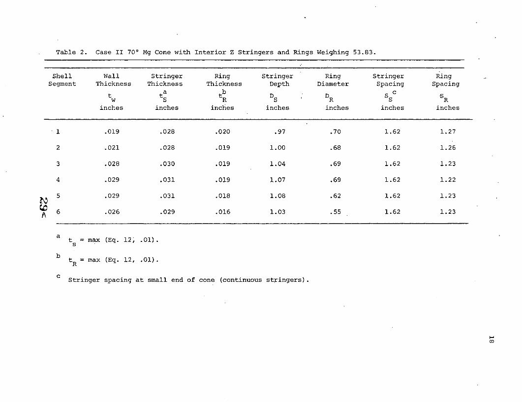
Table 2. Case II 700 Mg Cone with Interior Z Stringers and Rings Weighing 53.83.
Shell Wall Stringer Ring Stringer Ring Stringer RingSegment Thickness Thickness Thickness Depth Diameter Spacing Spacing
a b ct t t D D S Sw S R S R S R
inches inches inches inches inches inches inches
1 .019 .028 .020 .97 .70 1.62 1.27
2 .021 .028 .019 1.00 .68 1.62 1.26
3 .028 .030 .019 1.04 .69 1.62 1.23
4 .029 .031 .019 1.07 .69 1.62 1.22
5 .029 .031 .018 1.08 .62 1.62 1.23
6 .026 .029 .016 1.03 .55 1.62 1.23
t = max (Eq. 12, .01).s
bt = max (Eq. 12, .01).
Stringer spacing at small end of cone (continuous stringers).
CO
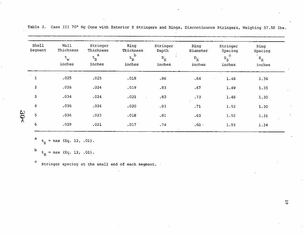
Table 3. Case III 700 Mg Cone with Interior Z Stringers and Rings, Discontinuous Stringers, Weighing 57.58 lbs.
Shell Wall Stringer Ring Stringer Ring Stringer RingSegment Thickness Thickness Thickness Depth Diameter Spacing Spacing
a b cw SR S R S R
inches inches inches inches inches inches inches
1 .025 .025 .018 .86 .64 1.48 1.36
2 .026 .024 .019 .83 .67 1.49 1.35
3 .034 .024 .021 .82 .73 1.48 1.30
4 .036 .024 .020 .83 .71 1.52 1.30
5 .036 .023 .018 .81 .63 1.52 1.31
6 .029 .021 .017 .74 .60 1.53 1.34
a t s = max (Eq. 12, .01).
bt R = max (Eq. 12, .01).
Stringer spacing at the small end of each segment.

Table 4. Case IV 700 Mg Cone with Exterior Z Stringers, Interior O Rings,. Weighing 71.77 ibs.
Shell Wall Stringer Ring Stringer Ring Stringer RingSegment Thickness Thickness Thickness Depth Diameter Spacing Spacing
a b dt t t D D S Sw S R S R S R
inches inches inches inches inches inches inches
1 .035 .038 .01c 1.32 1.21 2.64 2.22
2 .055 .042 .0 1c 1.46 1.10 2.64 2.19
3 .060 .059 .01c 2.05 1.03 2.64 2.19
4 .041 .059 .01c 2.07 .87 2.64 2.21
5 .032 .047 .01c 1.63 .85 2.64 2.20
6 .019 .039 .01c 1.37 .77 2.64 2.23
tS = max (Eq. 12, .01).
btR = max (Eq. 10, .01).
Minimum gage.
d Stringer spacing at small end of cone.
o

Table 5. Case VI Al Sphere Segment with Exterior Z Stringers and Interior Z Rings, Weighing 289.91 lbs.
Shell Wall Stringer Ring Stringer Ring Stringer RingSegment Thickness Thickness Thickness Depth Diameter Spacing Spacing
a b ct t t D D S Sw S R S R S R
inches inches inches inches inches inches inches
1 .048 .024 .024 .71 .70 2.07 2.01
2 .046 .024 .023 .71 .68 2.07 2.01
3 .043 .025 .023 .71 .66 2.07 2.01
4 .043 .024 ,023 .72 .66 2.07 2.01
A 5 .044 .023 .023 .66 .66 2.07 2.01
6 .044 .026 .022 .75 .64 2.07 2.00
ts = max (Eq. 12, .01).
btR = max (Eq. 17, .01).
Stringer spacing at small end of spherical segment.
22
30
I
/
90 in.
Fig. 1. Geometry and boundary conditions for spherical
segment, Case V.
q33<

23
Figure Caption
Fig. 1. Geometry and boundary condition for spherical segment,
Case V.
'34<