clarification question response delete. probes shall be volu-probe fi by air monitor corporation or...
TRANSCRIPT
DOCUMENT 00 0494 ADDENDUM NO. 4
Clinton County Justice Center – Bid Package #4 Construction Documents
Addendum # 4 / March 22, 2017 416315-0
00 0492-1
DATE: March 22, 2017 PROJECT NAME: Clinton County Justice Center – Bid Package #4 Construction Documents This Addendum forms a part of the bidding and contract documents. This Addendum supersedes and supplements all portions of the original bidding and contract documents dated, February 17, 2017 and Addendum No. 1 dated March 9, 2017, Addendum 2, dated March 10, 2017, and Addendum 3 dated March 16, 2017, with which it conflicts. ACKNOWLEDGE RECEIPT OF THIS ADDENDUM IN THE SPACE PROVIDED ON THE BID FORM. FAILURE TO DO SO MAY SUBJECT THE BIDDER TO DISQUALIFICATION.
A. GENERAL CLARIFICATIONS / QUESTIONS
1. CLARIFICATION: There is no burnished block on this project.
2. QUESTION: At what locations are fire-shutters to be provided? At what locations are storm-shutters to be provided?
RESPONSE: One (1) fire-shutter is to be provided in the 1-hour fire partition on the
second floor, at the pass-thru at storefront Type SF–INT–5, as keynoted on 6A/132B, and
as indicated on 6A/A501 and 2E/A604, detailed on Sheet A603.
One (1) fire-shutter is to be provided in the 1-hour fire partition on the second floor, at the
pass-thru at detention window Type 9 (Bid Package #2, Security & Detention), as
keynoted on 6A/132B, and as indicated on 2E/A213, detailed on Sheet A603.
Four (4) storm-shutters are to be provided at the three (3) instances of window Type 24 in Dispatch/Control [2037] and at the one (1) instance of window Type 24 in Supervisor Office [2041], as indicated on 6A/132B, and on Sheet A604, detailed on Sheet A603.
B. BIDDING REQUIREMENTS
1. SECTION 00 4100 – BID FORM
a. DELETE the Bid Form dated February 17, 2017 in its entirety and ADD the revised Bid Form in its entirety as attached to this addendum.
C. SPECIFICATIONS
1. SECTION 01 1100 – SUMMARY
a. Bid Category No. 5 – Metals, and Bid Category - Metal Erection. Delete requirements for 05 4000, Cold-Formed Metal Framing in its entirety from these bid categories.
b. Bid Category 5 & 5A Clarifications: Add the following clarification,
If a Bidder has a preference to provide Cold Form Metal Framing (L & M) associated with this work then, the bidder should indicated their interest providing this work on the Bid Form. Note a breakout price for this Work on the bid form as work associated with category 5 and 5A, ‘Cold Form Metal Framing Breakout Pricing.’ This work is in addition to the Work being provided in this Bid Category.
c. Bid Category No. 7D – Fire Stopping and Joint Sealants. Add the requirements for 07 8100, Applied Fireproofing for Labor (L) and Material (M) in its entirety to this bid category.
d. Bid Category No. 9 – Drywall. Add the requirements for 05 4000, Cold-Formed Metal Framing for Labor (L) and Material (M) in its entirety to this bid category.

DOCUMENT 00 0494 ADDENDUM NO. 4
Clinton County Justice Center – Bid Package #4 Construction Documents
Addendum # 4 / March 22, 2017 416315-0
00 0492-2
e. Bid Category 9 Clarifications: Add the following clarification,
With the inclusion to provide Cold Form Metal Framing (L & M) associated with this work then, the bidder shall provide a breakout price for this Work on the bid form labeled, ‘Cold Form Metal Framing Breakout Pricing.’ This work is included in the Work being provided in this Bid Category. Final evaluation determination for Work associated with Cold-Formed Metal Framing by Owner’s Representatives may be given depending on Bid Category 5 & 5A bid responses received.
2. SECTION 01 2300 – ALTERNATES
a. Part 1.7, Schedule of Alternate. Add the following.
G. Alternate No. 7 – Dayroom Demising Walls as Concrete Masonry Unit Walls:
1. Base Bid Item: Through Bid Package No. 2 (bid separately) Dayroom Demising Walls from Modular Cell Fronts to Central Control Modules (1009, 2009). Walls between Dayrooms A, B, C, D, E, F, Exercise Yard (1010), G, H, J, Corridor (1012), remain as Steel Modular Components.
2. Alternate Item: Provide Alternate Bid to include Dayroom Demising Walls from Modular Cell Fronts to Central Control Modules (1009, 2009). Walls between Dayrooms A, B, C, D, E, F, Exercise Yard (1010), G, H, J, Corridor (1012), shall be constructed as a Minimum Security Concrete Masonry Wall, 12-inch thick, to a height of 20’-8”. Top of Wall Bracing to be provided by others. Security Wall Type Requirements on Drawing Sheet DS700. Stair (1013), and Control Corridor (1009) as Pod / Floor Control (1009, 2009) to remain as Steel Control Room Modules.
3. SECTION 07 8100 - APPLIED FIREPROOFING
a. ADD Section 07 8100 in its entirety as attached to this addendum.
4. SECTION 07 8123 - INTUMESCENT MASTIC FIREPROOFING
a. CLARIFICATION. Part 1.1.A. Add the following,
1. This Product is intended to be applied on a limited basis where Section 07 8100 – Applied Fireproofing, will not achieve the code coverage required results due to limited space constraints or, the ‘steel condition’ in question is exposed to an occupied space where mastic fireproofing would then be preferred.
5. SECTION 09 2216
a. ADD Article 2.2K, to read as follows: Tracks and Runners with Intumescent Coating:
1. Same material, width and thickness as studs, with manufacturer-applied intumescent coating (2mm thick, minimum), as indicated on drawings.
2. Products:
a. ClarkDietrich; BlazeFrame Firestop Deflection Track: www.clarkdietrich.com
b. Substitutions: See Section 01 6000 – Product Requirements

DOCUMENT 00 0494 ADDENDUM NO. 4
Clinton County Justice Center – Bid Package #4 Construction Documents
Addendum # 4 / March 22, 2017 416315-0
00 0492-3
6. SECTION 11 4000
a. Article 2.3 Itemized Specifications
1. REVISE subparagraph 2.3.BF.1 to read as follows: “1. See Division 23 Section "Commercial Kitchen Hoods" for ventilation hood specifications.”
7. SECTION 23 0900
a. ADD subparagraph 2.15 which reads:
2.15 AIR FLOW MONITORING DEVICES (AT FAN INLETS)
A. Furnish fan inlet airflow probes to traverse the inlet of a fan. The
probe shall be capable of continuously measuring the air handling
unit air volume for the respective fan. Coordinate the number of
inlets required with fan type indicated on the drawings.
B. The probes shall not adversely affect the performance of the fan and
shall have an accuracy of 3% of the actual flow based on a 6:1
turndown ratio.
C. Probes shall be VOLU-probe FI by Air Monitor Corporation or
engineer approved equivalent.
b. REVISE remaining paragraph numbers to remain consistent.
8. SECTION 23 5938
a. ADD specification to project manual as attached to this addendum.
9. SECTION 23 7313
a. REVISE subparagraph 2.11.A.2. to read as follows: “Each fan shall have a VFD in lieu of all fans wired to a single VFD and a backup VFD. The unit shall maintain single point power connection.”
10. SECTION 23 7314
a. REVISE subparagraph 2.9.O.2. to read as follows: “Each fan shall have a VFD in lieu of all fans wired to a single VFD and a backup VFD. The unit shall maintain single point power connection.”
D. DRAWINGS
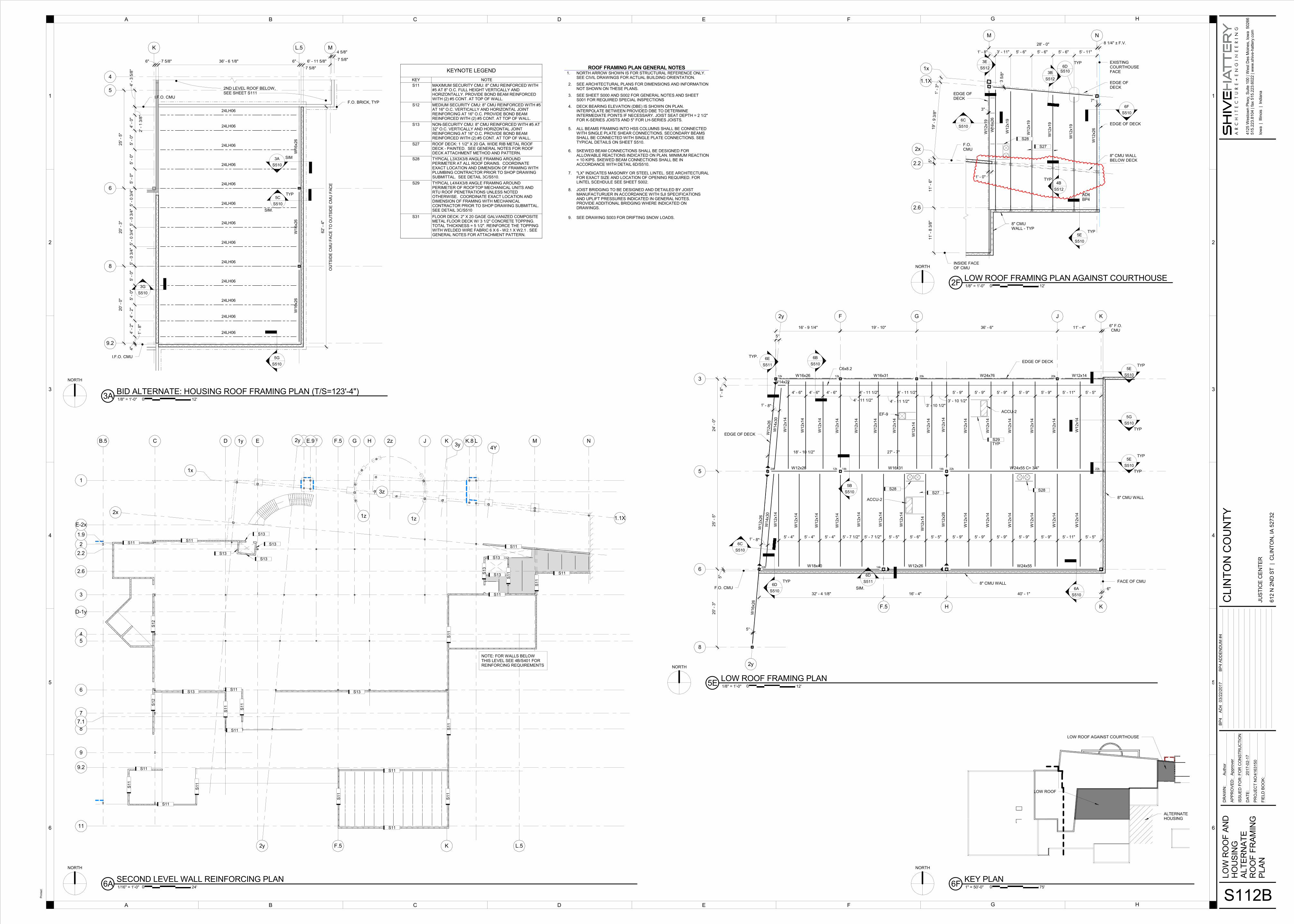
1. SHEET S112B
a. REPLACE Sheet S112B with NEW Sheet S112B as attached to this addendum.
2. SHEET A113A
a. REPLACE Sheet S113A with NEW Sheet S113A as attached to this addendum.
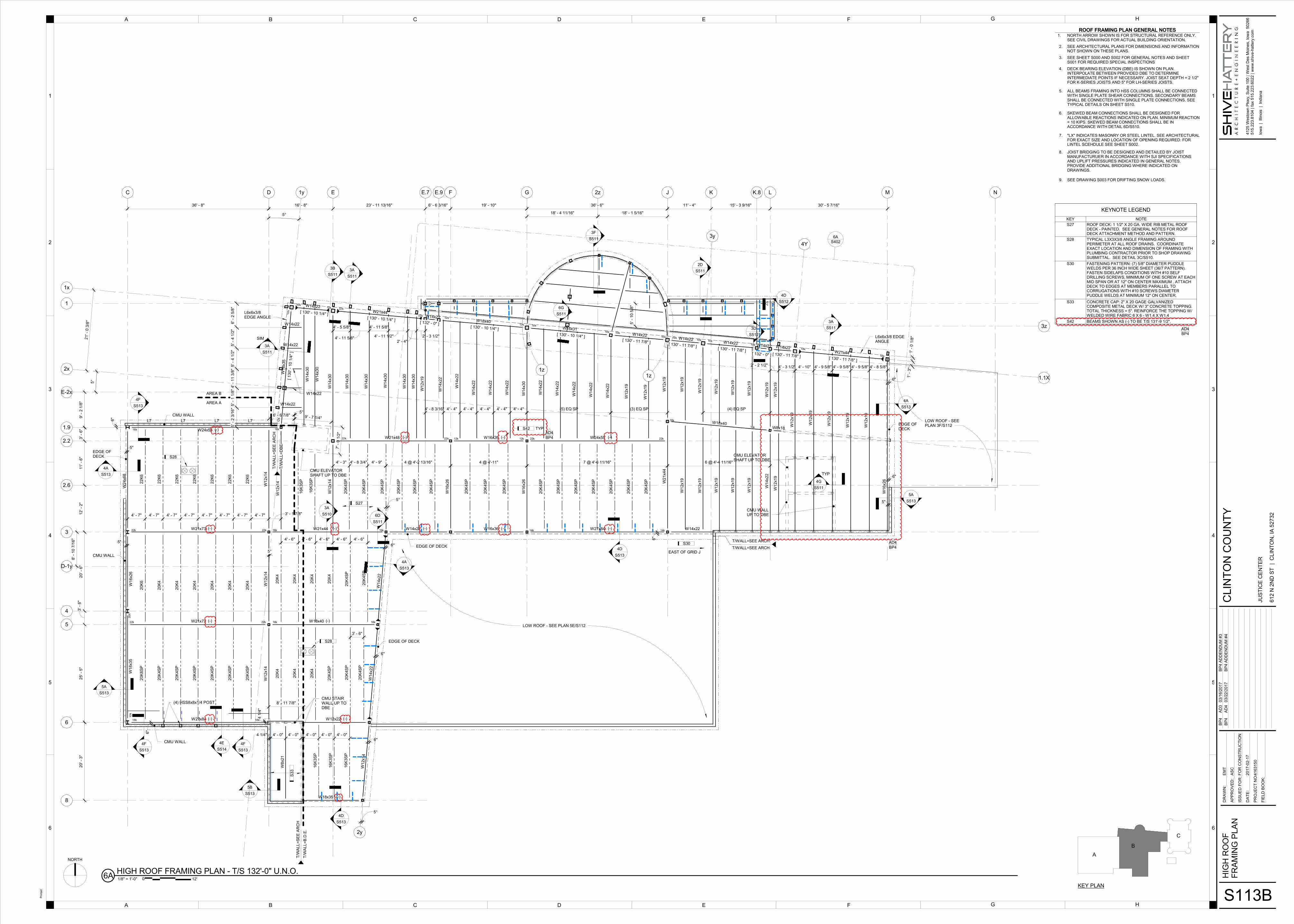
3. SHEET A113B
a. REPLACE Sheet S113B with NEW Sheet S113B as attached to this addendum.
4. SHEET S510
a. REPLACE Sheet S510 with NEW Sheet S510 as attached to this addendum.
5. SHEET S511
a. REPLACE Sheet S511 with NEW Sheet S511 as attached to this addendum.

DOCUMENT 00 0494 ADDENDUM NO. 4
Clinton County Justice Center – Bid Package #4 Construction Documents
Addendum # 4 / March 22, 2017 416315-0
00 0492-4
6. SHEET S512
a. REPLACE Sheet S512 with NEW Sheet S512 as attached to this addendum.
7. SHEET S513
a. REPLACE Sheet S513 with NEW Sheet S513 as attached to this addendum.
8. SHEET A325
a. Detail 6C: DELETE “Burnished” from “solid burnished CMU cap w/bullnose edge” and “burnished concrete masonry bond beam”.
9. SHEET FP111B
a. ADD room 1068 SECURITY ELECTRONICS to preaction sprinkler system. Provide with dedicated preaction valve to be located in same location as other preaction valve and dry valve. Both preaction valves and detectors to share common multi-zone controller.
10. SHEET M110C
a. REVISE note M13. Delete reference to existing building automation system. New thermostat shall be a part of new BAS system.
11. SHEET M111C
a. REVISE note M13. Delete reference to existing building automation system. New thermostat shall be a part of new BAS system.
12. SHEET M112C
a. REVISE note M13. Delete reference to existing building automation system. New thermostat shall be a part of new BAS system.
13. SHEET M113C
a. REVISE note M13. Delete reference to existing building automation system. New thermostat shall be a part of new BAS system.
14. SHEET M114C
a. REVISE note M13. Delete reference to existing building automation system. New thermostat shall be a part of new BAS system.
15. SHEET M213AB
a. REPLACE sheet M213AB with NEW Sheet M213AB as attached to this addendum.
16. SHEET M502
a. REVISE RTU-1 & RTU-2 details. Airflow Measuring Stations (AMS) shall be by controls contractor to match revision issued in addendum #1. AMSs are located in minimum outdoor air opening for RTU-1, minimum outdoor air and exhaust air inlet openings in RTU-2.
b. ADD note to RTU-1 & RTU-2 details which reads: “FANS ARE SHOWN TO DEPICT MULTIPLE FAN ARRAY. SEE SCHEDULES FOR ACTUAL QUANTITY OF FANS.”
17. SHEET M503
a. DELETE BI – Refrigerant Leak shutdown from both chillers. There is no refrigerant monitoring required for this project.

DOCUMENT 00 0494 ADDENDUM NO. 4
Clinton County Justice Center – Bid Package #4 Construction Documents
Addendum # 4 / March 22, 2017 416315-0
00 0492-5
18. SHEET M505
a. REVISE location of minimum outdoor air flow station in RTU-1 & RTU-2 schematics. Outdoor air flow station shall be upstream of motorized dampers. Outdoor air flow station shall be installed per manufacturer’s instructions for accurate readings.
19. SHEET M507
a. DELETE direct digital controls interface with Div 26. No monitoring of incoming power is required for this project.
20. SHEET E201C
a. ADD the following to keynote E19 – Existing fire alarm system has 15 zones, 33 horn/strobes, 46 strobes, 20 contact type initiating devices, 113 two-wire smoke detectors, 1 NAC extender, and 6 door holder connections.
E. APPROVED MANUFACTUERS
The following manufacturers are approved for this project, provided the materials and systems meet the requirements of these Contract Documents. This approval does not waive any requirements or conditions of the Contract Documents for any material, system, or manufacturer.
SECTION ITEM SUBSTITUTION
07 5323 EPDM Roofing Versico Roofing Systems
22 3400 Water Heaters Rheem SPIDERfire Condensing Water Heater
22 3400 Domestic Water Heater Watts Series DE23 2113TA
22 3400 Fuel-Fired Domestic Water Heaters
Bock OT400N-A Sealed Combustion High Efficiency Water
Heater
22 1423 Storm Drainage Special 2.2& 2.3
Watts Drainage
22 4000 Plumbing Fixtures Guardian G1760 Eye/Face Wash
22 4000 Plumbing Fixtures Powers HydroGuard XP Series Emergency Tempering Valve
22 4000 Plumbing Fixtures Powers Biltmore Series 900 Pressure Balancing Mixing Valve /
Model 3
22 4000 Plumbing Fixtures 2.1-7 Watts Drainage
23 2113 Hydronic Piping Watts Series ET-RA
23 2500 Propylene Glycol 2.2 Rhomar Water EnviroGard Ultra
23 3113 Metal Ducts Lapine Metal Products
23 7313 & 23 7314 Custom AHU & Modular Central-Station AHU
ATMI Climate Solutions Custom AHUs
F. ATTACHMENTS
1. Section 00 4100
2. Section 07 8100
3. Section 23 5938
4. Sheet S112B

DOCUMENT 00 0494 ADDENDUM NO. 4
Clinton County Justice Center – Bid Package #4 Construction Documents
Addendum # 4 / March 22, 2017 416315-0
00 0492-6
5. Sheet S113A
6. Sheet S113B
7. Sheet S510
8. Sheet S511
9. Sheet S512
10. Sheet S513
11. Sheet M213AB
Prepared By: Shive-Hattery, Inc.
END OF DOCUMENT 00 0494
I hereby certify that this engineering document was prepared by me or under my direct personal supervision and that I am a duly licensed Professional Engineer under the laws of the State of Iowa.
Signature Date
Printed or typed name
Michael S. Lewis. AIA
License Number 03968
My License Renewal Date is:
06-30-2017
Pages, Sheets, or Divisions covered by this Seal: This Addendum
Clinton County - Justice Center Project # 416315-0
00 41 00 - 1 BID FORM
BID PACKAGE #4 Construction Documents
BID FORM
Revised 3-22-2017 by Addendum No 4.
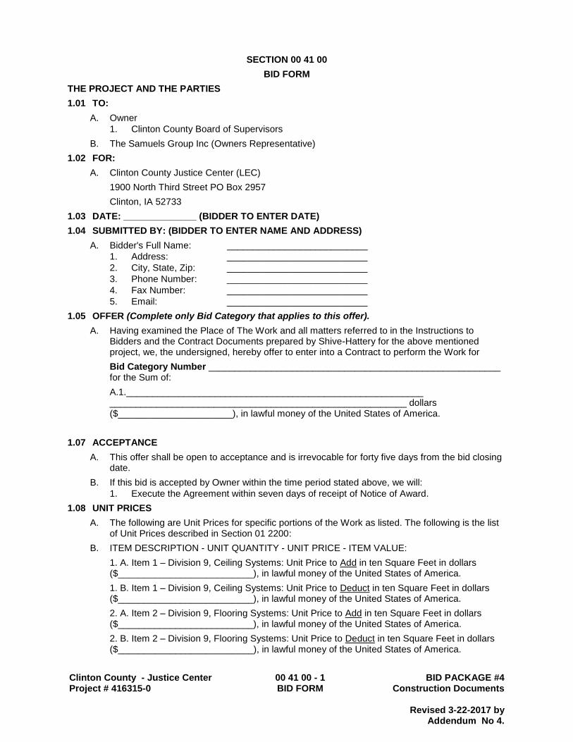
SECTION 00 41 00
BID FORM
THE PROJECT AND THE PARTIES
1.01 TO:
A. Owner
1. Clinton County Board of Supervisors
B. The Samuels Group Inc (Owners Representative)
1.02 FOR:
A. Clinton County Justice Center (LEC)
1900 North Third Street PO Box 2957
Clinton, IA 52733
1.03 DATE: ______________ (BIDDER TO ENTER DATE)
1.04 SUBMITTED BY: (BIDDER TO ENTER NAME AND ADDRESS)
A. Bidder's Full Name: ___________________________
1. Address: ___________________________
2. City, State, Zip: ___________________________
3. Phone Number: ___________________________
4. Fax Number: ___________________________
5. Email: ___________________________
1.05 OFFER (Complete only Bid Category that applies to this offer).
A. Having examined the Place of The Work and all matters referred to in the Instructions to Bidders and the Contract Documents prepared by Shive-Hattery for the above mentioned project, we, the undersigned, hereby offer to enter into a Contract to perform the Work for
Bid Category Number ________________________________________________________ for the Sum of:
A.1._________________________________________________________ _________________________________________________________ dollars ($______________________), in lawful money of the United States of America.
1.07 ACCEPTANCE
A. This offer shall be open to acceptance and is irrevocable for forty five days from the bid closing date.
B. If this bid is accepted by Owner within the time period stated above, we will:
1. Execute the Agreement within seven days of receipt of Notice of Award.
1.08 UNIT PRICES
A. The following are Unit Prices for specific portions of the Work as listed. The following is the list of Unit Prices described in Section 01 2200:
B. ITEM DESCRIPTION - UNIT QUANTITY - UNIT PRICE - ITEM VALUE:
1. A. Item 1 – Division 9, Ceiling Systems: Unit Price to Add in ten Square Feet in dollars ($__________________________), in lawful money of the United States of America.
1. B. Item 1 – Division 9, Ceiling Systems: Unit Price to Deduct in ten Square Feet in dollars ($__________________________), in lawful money of the United States of America.
2. A. Item 2 – Division 9, Flooring Systems: Unit Price to Add in ten Square Feet in dollars ($__________________________), in lawful money of the United States of America.
2. B. Item 2 – Division 9, Flooring Systems: Unit Price to Deduct in ten Square Feet in dollars ($__________________________), in lawful money of the United States of America.

Clinton County - Justice Center Project # 416315-0
00 41 00 - 2 BID FORM
BID PACKAGE #4 Construction Documents
BID FORM
Revised 3-22-2017 by Addendum No 4.
3. A. Item 3 – Division 31, Earthwork: Unit Price to Add per cubic yard in dollars ($_________________________), in lawful money of the United States of America.
3. B. Item 3 – Division 31, Earthwork: Unit Price to Deduct in cubic yard in dollars ($_________________________), in lawful money of the United States of America.
4. A. Item 4 – Division 9, Wall Systems: Unit Price to Add in ten Square Feet in dollars ($__________________________), in lawful money of the United States of America.
4. B. Item 4 – Division 9, Wall Systems: Unit Price to Deduct in ten Square Feet in dollars ($__________________________), in lawful money of the United States of America.
1.09 ALTERNATE BIDS
Alternative Bids are more fully described in Section 01 23 00 of the Specifications. All Prime Bidders must indicate the stipulated sum to be added to or deducted from their Base Bid or indicate "no change". A "no bid" entry, or failure to enter a sum will be considered a "no change" to the Base Bid.
ALTERNATIVE BID NO. 1 – Public Lobby Floor Finishes.
Provide Ground and Polished Concrete Flooring as indicated on the drawings and as specified in Section 03 3000 and Section 03 3520, including floor and ramp finishes as noted on alternate finish plans, as shown on Drawing Sheet A150, for rooms (Lobby – 1033 and Second Floor Lobby – 2012) and as detailed on the drawings. Stair finishes to remain resinous matrix terrazzo, as indicated the base bid, under this alternate. If the Owner elects to accept this alternative, add or deduct from my (our) Base Bid the stipulated sum of ____________________________________________ Dollars ( $ _______________________________)
(Indicate (Add), (Deduct) or (No Bid) for Base Bid Scope of Work). ALTERNATIVE BID NO. 2 - Public Lobby Ceiling Finishes.
Provide Suspended Acoustical Ceiling systems as indicated on the drawings, sheet A150 and associated details, and as specified in Section 09 5100 including associated trim and finish elements Division 6, “Interior Finish Carpentry,” and other related sections associated with finish plans for rooms (Lobby – 1033 and Second Floor Lobby – 2012) and as detailed on the drawings. If the Owner elects to accept this alternative, add or deduct from my (our) Base Bid the stipulated sum of ____________________________________________ Dollars ( $ _______________________________)
(Indicate (Add), (Deduct) or (No Bid) for Base Bid Scope of Work).
ALTERNATIVE BID NO. 3 - Additional Housing Shell Space Construction.
Provide Alternate Bid for construction as shown on Drawings Sheets A100 and A112A, plan details 3A and 6A, for additional shell space construction as detailed throughout the drawing set and as specified. If the Owner elects to accept this alternative, add from my (our) Base Bid the stipulated sum of ____________________________________________ Dollars ( $ _______________________________)
(Indicate (Add) or (No Bid) for Base Bid Scope of Work).
ALTERNATIVE BID NO. 4 - Exterior Window Construction, Material and Installation Change.
Provide Alternate Bid Construction for exterior window opening as indicated in the drawings and as specified in Section 08 4313, Aluminum Framed Storefronts. This alternate includes required supplemental delegated design engineering needed, to deviate from the base bid condition. If the Owner elects to accept this alternative, add or deduct from my (our) Base Bid the stipulated sum of ____________________________________________ Dollars ( $ _______________________________) (Indicate (Add), (Deduct) or (No Bid) for Base Bid Scope of Work).

Clinton County - Justice Center Project # 416315-0
00 41 00 - 3 BID FORM
BID PACKAGE #4 Construction Documents
BID FORM
Revised 3-22-2017 by Addendum No 4.
ALTERNATIVE BID NO. 5 - Canopy at Loading Dock / Vehicle Evidence.
Provide Alternate Bid to exclude the Canopy of the Southside of Building in its entirety over the loading dock and vehicle evidence. If the Owner elects to accept this alternative, deduct from my (our) Base Bid the stipulated sum of ____________________________________________ Dollars ( $ _______________________________) (Indicate (Deduct) or (No Bid) for Base Bid Scope of Work). ALTERNATIVE BID NO. 6 - Mechanical ‘Fan Coil’ Retrofit Work in Existing Courthouse. Provide Alternate Bid to exclude HVAC retrofit conversion work, associated piping, and electrical on drawing sheets
M110C, M111C, M112C, M113C, M114C, MD10C, MD11C, MD12C, MD13C, MD14C, E200C, E201C, E202C, E203C, and E204C. This alternate removes the associated cutting and patching in the existing building to complete the installation of the HVAC Retrofit Work in the courthouse. If the Owner elects to accept this alternative, deduct from my (our) Base Bid the stipulated sum of ____________________________________________ Dollars ( $ _______________________________) (Indicate (Deduct) for Base Bid Scope of Work). ALTERNATIVE BID NO. 7 – Concrete Masonry Dayroom Demising Walls.
Provide Alternate Bid to include Dayroom Demising Walls from Modular Cell Fronts to Central Control Modules (1009, 2009). Walls between Dayrooms A, B, C, D, E, F, Exercise Yard (1010), G, H, J, Corridor (1012), shall be constructed as a Minimum Security Concrete Masonry Wall, 12-inch thick, to a height of 20’-8”. Top of Wall Bracing to be provided by others. Security Wall Type Requirements on Drawing Sheet DS700. Stair (1013), and Control Corridor (1009) as Pod / Floor Control (1009, 2009) to remain as Steel Control Room Modules. If the Owner elects to accept this alternative, Add from my (our) Base Bid the stipulated sum of ____________________________________________ Dollars ( $ _______________________________) (Indicate (Deduct) for Base Bid Scope of Work).
1.10 CHANGES TO THE WORK
A. When Architect establishes that the method of valuation for Changes in the Work will be net cost plus a percentage fee in accordance with General Conditions, our percentage fee will be:
1. __10____ percent overhead and profit on the net cost of our own Work;
2. ___5___ percent on the cost of work done by any Subcontractor.
1.11 ADDENDA
A. The following Addenda have been received. The modifications to the Bid Documents noted below have been considered and all costs are included in the Bid Sum.
1. Addendum # _______ Dated ________________.
2. Addendum # _______ Dated ________________.
1.12 BID FORM SUPPLEMENTS
A. The following Supplements are attached to this Bid Form and are considered an integral part of this Bid Form:
1. Document 00 21 13 Exhibit D – Subcontractors List: Include a list of all Subcontractors and their type of work as specifically requested by the Contract Documents.
2. Document 00 21 13 – Bid Security: Include the required Bid Security.
3. Document 00 21 13 – Performance and labor Bond: Include the required Performance and Payment Bond.
Clinton County - Justice Center Project # 416315-0
00 41 00 - 4 BID FORM
BID PACKAGE #4 Construction Documents
BID FORM
Revised 3-22-2017 by Addendum No 4.
1.13 BID FORM SIGNATURE(S)
A. The Corporate Seal of
B. ____________________________________________
C. (Bidder - print the full name of your firm)
D. was hereunto affixed in the presence of:
E. ____________________________________________
F. (Authorized signing officer, Title)
G. (Seal)
H. ____________________________________________
I. (Authorized signing officer, Title)
1.14 IF THE BID IS A JOINT VENTURE OR PARTNERSHIP, ADD ADDITIONAL FORMS OF EXECUTION FOR EACH MEMBER OF THE JOINT VENTURE IN THE APPROPRIATE FORM OR FORMS AS ABOVE.
END OF BID FORM
Clinton County Law Enforcement Center
Bid Package #4 Construction Documents
APPLIED FIREPROOFING
Project # 4163150 02-17-2017 (addenda issue date 03-22-2017)
07 8100-1
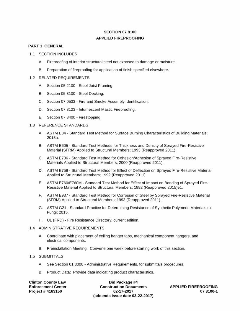
SECTION 07 8100
APPLIED FIREPROOFING
PART 1 GENERAL
1.1 SECTION INCLUDES
A. Fireproofing of interior structural steel not exposed to damage or moisture.
B. Preparation of fireproofing for application of finish specified elsewhere.
1.2 RELATED REQUIREMENTS
A. Section 05 2100 - Steel Joist Framing.
B. Section 05 3100 - Steel Decking.
C. Section 07 0533 - Fire and Smoke Assembly Identification.
D. Section 07 8123 - Intumescent Mastic Fireproofing.
E. Section 07 8400 - Firestopping.
1.3 REFERENCE STANDARDS
A. ASTM E84 - Standard Test Method for Surface Burning Characteristics of Building Materials; 2015a.
B. ASTM E605 - Standard Test Methods for Thickness and Density of Sprayed Fire-Resistive Material (SFRM) Applied to Structural Members; 1993 (Reapproved 2011).
C. ASTM E736 - Standard Test Method for Cohesion/Adhesion of Sprayed Fire-Resistive Materials Applied to Structural Members; 2000 (Reapproved 2011).
D. ASTM E759 - Standard Test Method for Effect of Deflection on Sprayed Fire-Resistive Material Applied to Structural Members; 1992 (Reapproved 2011).
E. ASTM E760/E760M - Standard Test Method for Effect of Impact on Bonding of Sprayed Fire-Resistive Material Applied to Structural Members; 1992 (Reapproved 2015)e1.
F. ASTM E937 - Standard Test Method for Corrosion of Steel by Sprayed Fire-Resistive Material (SFRM) Applied to Structural Members; 1993 (Reapproved 2011).
G. ASTM G21 - Standard Practice for Determining Resistance of Synthetic Polymeric Materials to Fungi; 2015.
H. UL (FRD) - Fire Resistance Directory; current edition.
1.4 ADMINISTRATIVE REQUIREMENTS
A. Coordinate with placement of ceiling hanger tabs, mechanical component hangers, and electrical components.
B. Preinstallation Meeting: Convene one week before starting work of this section.
1.5 SUBMITTALS
A. See Section 01 3000 - Administrative Requirements, for submittals procedures.
B. Product Data: Provide data indicating product characteristics.

Clinton County Law Enforcement Center Project # 4163150
APPLIED FIREPROOFING Bid package #4 Construction Documents
07 8100-2 02-17-2017 (Addenda issue date 03-22-2017)
1.6 QUALITY ASSURANCE
A. Manufacturer Qualifications: Company specializing in manufacturing products specified in this section, with not less than three years of documented experience.
B. Installer Qualifications: Company specializing in performing work of the type specified in this section, and:
1. Approved by manufacturer.
1.7 FIELD CONDITIONS
A. Do not apply spray fireproofing when temperature of substrate material and surrounding air is below 40 degrees F (4 degrees C) or when temperature is predicted to be below said temperature for 24 hours after application.
B. Provide ventilation in areas to receive fireproofing during application and 24 hours afterward, to dry applied material.
C. Provide temporary enclosure to prevent spray from contaminating air.
1.8 WARRANTY
A. See Section 01 7800 - Closeout Submittals, for additional warranty requirements.
B. Correct defective Work within a five year period after Date of Substantial Completion.
1. Include coverage for fireproofing to remain free from cracking, checking, dusting, flaking, spalling, separation, and blistering.
2. Reinstall or repair failures that occur within warranty period.
PART 2 PRODUCTS
2.1 MANUFACTURERS
A. Sprayed-On Fireproofing:
1. Carboline Company: www.carboline.com.
2. GCP Applied Technologies: www.gcpat.com/fireproofing/sle.
3. Southwest Fireproofing Products Company: www.sfrm.com.
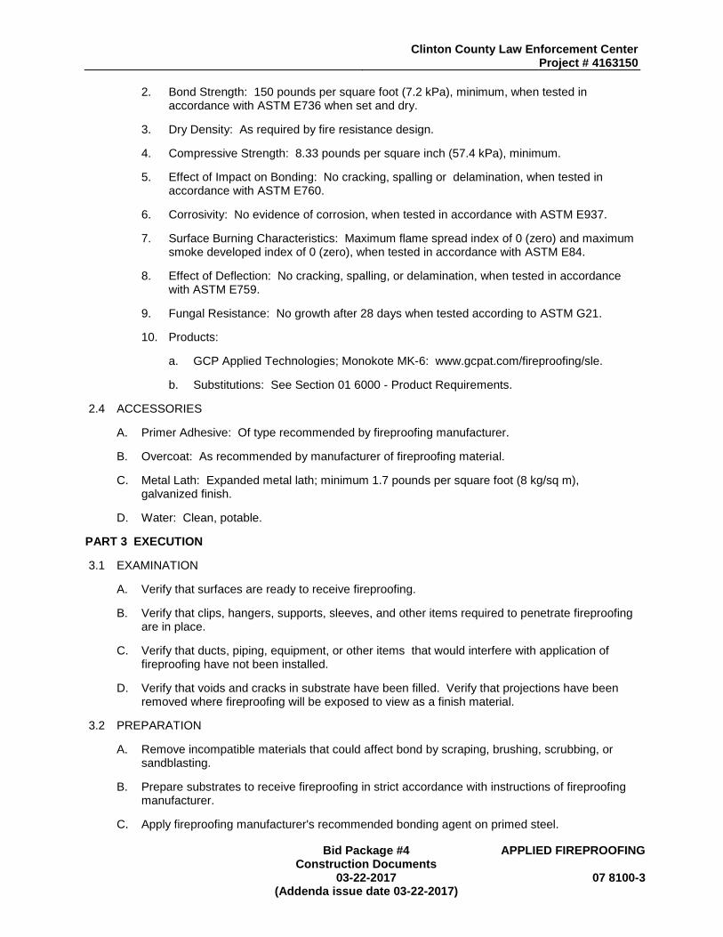
2.2 FIREPROOFING ASSEMBLIES
A. Provide fire resistance ratings for the following building elements as required by the building code and as indicated on the Life Safety Code Drawings:
1. Primary structural frame, including columns, beams and structural elements to achieve UL rated condition: at I-3 to B Occupancy Floor Construction: 1 hour.
2.3 MATERIALS
A. Sprayed Fire-Resistive Material for Interior Applications, Concealed: Manufacturer's standard factory mixed material, which when combined with water is capable of providing the indicated fire resistance, and conforming to the following requirements:
1. Composition: Gypsum-based; not mineral-fiber-based.
Clinton County Law Enforcement Center Project # 4163150
Bid Package #4 Construction Documents
APPLIED FIREPROOFING
03-22-2017 (Addenda issue date 03-22-2017)
07 8100-3
2. Bond Strength: 150 pounds per square foot (7.2 kPa), minimum, when tested in accordance with ASTM E736 when set and dry.
3. Dry Density: As required by fire resistance design.
4. Compressive Strength: 8.33 pounds per square inch (57.4 kPa), minimum.
5. Effect of Impact on Bonding: No cracking, spalling or delamination, when tested in accordance with ASTM E760.
6. Corrosivity: No evidence of corrosion, when tested in accordance with ASTM E937.
7. Surface Burning Characteristics: Maximum flame spread index of 0 (zero) and maximum smoke developed index of 0 (zero), when tested in accordance with ASTM E84.
8. Effect of Deflection: No cracking, spalling, or delamination, when tested in accordance with ASTM E759.
9. Fungal Resistance: No growth after 28 days when tested according to ASTM G21.
10. Products:
a. GCP Applied Technologies; Monokote MK-6: www.gcpat.com/fireproofing/sle.
b. Substitutions: See Section 01 6000 - Product Requirements.
2.4 ACCESSORIES
A. Primer Adhesive: Of type recommended by fireproofing manufacturer.
B. Overcoat: As recommended by manufacturer of fireproofing material.
C. Metal Lath: Expanded metal lath; minimum 1.7 pounds per square foot (8 kg/sq m), galvanized finish.
D. Water: Clean, potable.
PART 3 EXECUTION
3.1 EXAMINATION
A. Verify that surfaces are ready to receive fireproofing.
B. Verify that clips, hangers, supports, sleeves, and other items required to penetrate fireproofing are in place.
C. Verify that ducts, piping, equipment, or other items that would interfere with application of fireproofing have not been installed.
D. Verify that voids and cracks in substrate have been filled. Verify that projections have been removed where fireproofing will be exposed to view as a finish material.
3.2 PREPARATION
A. Remove incompatible materials that could affect bond by scraping, brushing, scrubbing, or sandblasting.
B. Prepare substrates to receive fireproofing in strict accordance with instructions of fireproofing manufacturer.
C. Apply fireproofing manufacturer's recommended bonding agent on primed steel.

Clinton County Law Enforcement Center Project # 4163150
APPLIED FIREPROOFING Bid package #4 Construction Documents
07 8100-4 02-17-2017 (Addenda issue date 03-22-2017)
D. Protect surfaces not scheduled for fireproofing and equipment from damage by overspray, fall-out, and dusting.
E. Close off and seal duct work in areas where fireproofing is being applied.
3.3 APPLICATION
A. Apply primer adhesive in accordance with manufacturer's instructions.
B. Apply fireproofing in thickness and density necessary to achieve required ratings, with uniform density and texture.
3.4 FIELD QUALITY CONTROL
A. See Section 01 4000 - Quality Requirements and 01 4325 - Code Required Special Inspection, for additional requirements.
B. Inspect the installed fireproofing after application and curing for integrity, prior to its concealment. Ensure that actual thicknesses, densities, and bond strengths meet requirements for specified ratings and requirements of the Authority Having Jurisdiction.
C. Re-inspect the installed fireproofing for integrity of fire protection, after installation of subsequent Work.
3.5 CLEANING
A. Remove excess material, overspray, droppings, and debris.
B. Remove fireproofing from materials and surfaces not required to be fireproofed.
END OF SECTION

Clinton County Law Enforcement Center
Bid Package #4 Construction Documents
EXHAUST FUME DETECTION
SYSTEM Project # 4163150 02-17-2017
(Addenda issue date 03-22-2017) 23 5938-1
SECTION 23 5938
EXHAUST FUME DETECTION SYSTEM
PART 1 GENERAL
1.1 SECTION INCLUDES
A. Provide equipment, material, devices, labor, wiring, and supervision necessary to fabricate and erect an Exhaust Fume Detection System as required by the Drawings and this section. The system will be installed in the ambulance garage. The system shall be suitable for monitoring emissions of both gasoline and diesel engines. All control wiring shall be coordinated with the Temperature Controls Contractor. The exhaust fume detection system shall be furnished, installed and certified operational by the Mechanical Contractor.
B. The system shall include a control panel with the CO and NO2 remote sensors.
1.2 CODES AND REGULATIONS
A. System design, equipment, materials, devices, and installation shall conform to NFPA Codes and Requirements of Governmental Bodies and Bureaus including FM & FIA, Local Fire Department, State Fire Marshall, City Building Department, Fire Insurance Rating Bureau, International Building Code
1.3 TESTS AND CERTIFICATION
A. Contractor shall test system in accordance with requirements of FM and FIA. Tests shall be conducted in the presence of the authority having jurisdiction and the Engineer/Architect. The Contractor shall have available at the site, a copy of the prescribed test. Contractor shall give ample notice as to time for conducting tests.
B. Should any component of the system fail the prescribed test, Contractor shall replace such component as required to pass the test.
C. Upon completion of installation and test, Contractor shall prepare Contractor's Material and Test Certificate. Certificate shall furnish copies of the signed Certificate to Authorities Having Jurisdiction, Owner, Insurance Rating Bureau, and Engineer/Architect.
1.4 WIRING
A. Coordinate with the Electrical Contractor to furnish power wiring for fans and central control furnished by this Contractor. All other wiring, including control and sensing shall be furnished by this Contractor. Submit control shop drawings of equipment and control sequences prior to installation. Interface system outputs with the Temperature Control Contractor.
1.5 INSTRUCTIONS
A. The Owner shall be thoroughly instructed in the operation and maintenance of this system for whatever period of time (maximum eight (4) hours) necessary for the Owner's complete understanding of the operation and routine maintenance.
1. The Owner shall sign a certification indicating that he received the instructions that they were complete and satisfactory, and that the Owner understands the operation and maintenance of the system.

Clinton County Law Enforcement Center Project # 4163150
EXHAUST FUME DETECTION SYSTEM
Bid Package #4 Construction Documents
23 5938-2 02-17-2017 (Addenda issue date 03-22-2017)
PART 2 PRODUCTS
2.1 EQUIPMENT
A. Supply, install and connect an Exhaust Fume Control System as manufactured by ACME Engineering Products, Vulcain, Toxalert, or approved equal.
B. The control panel shall allow for user interface include LED light for power on and at least two levels of detection. The panel shall include a relay to start/stop the 1/2 Hp ventilation fan serving the garage area. The control panel shall include self diagnostic test that will alarm when sensors have failed. The control panel shall have battery-back up and an audible alarm. The system shall be expandable to 8 additional sensors.
C. The control panel housing shall be a NEMA 4 enclosure.
D. Equipment shall include the following basic features:
1. Remote sampling heads with built-in filters for space mounting, located as recommended by the manufacturer. Install a minimum of one head in the space.
2. CO and NO2 sensors shall maintain a minimum accuracy of 5%. The CO and NO2 sensor shall be the solid-state type. Unit shall be rated for operation in temperatures between 19 degrees to 105 degrees F.
3. Response time of sensor to be in the order of a few minutes in order to avoid frequent or unnecessary adjustments of ventilation equipment due to short temporary conditions. There shall be practically no maintenance required except for simple calibration checks performed by introducing a known CO and/or NO2 gas mixture into the sensor chamber.
4. Output relay boards with one operating and one alarm output for each sampling point. Provide a 4-20mA or 0-10V signal for monitoring by the Temperature Control Contractor.
5. CO modules one for each sampled point shall be fully electronic incorporating solid state circuitry, with plug-in electronic board, factory calibrated to operate at 35 PPM and 100 PPM CO. Electronic board shall incorporate LED lights. Sensor and electronics shall include necessary temperature compensating circuits.
6. The NO2 sensor shall be factory calibrated to detect in the range of 0-10 ppm.
7. Enclosure shall have no adjustments accessible from the outside. Indicating light display condition at each point.
2.2 OPERATION
A. The control panel shall be accessed and provide the programmer the capabilities to change setpoints for the activation relays.
2.3 SYSTEMS OPERATIONAL CONTROL
A. See Temperature Controls for interface with control system.
2.4 FACTORY TESTING
A. Equipment shall be run for one week at the factory fully operational on simulator prior to shipment to the field. Records of testing shall be submitted to engineers.

Clinton County Law Enforcement Center Project # 4163150
Bid Package #4 Construction Documents
EXHAUST FUME DETECTION SYSTEM
02-17-2017 (Addenda issue date 03-22-2017)
23 5938-3
2.5 FIELD VERIFICATION
A. After the equipment has been put into operation with settings based on the estimated AQI (Air Quality Index), the owner-operator shall select the worst condition time for verification. The Manufacturer's Representative shall come to the site at the specified time and measure the level of contaminants as maintained by the initial settings and readjust these up or down according to conditions specific to the area served by the system. A report shall be submitted to the Owner's Representative.
PART 3 EXECUTION
3.1 INSTALLATION
A. General: Comply with applicable codes and these Specifications. Install the Detection System in accordance with manufacturer's written instructions and in accordance with recognized industry standards and practices to assure Owner that the system serves the intended purpose.
B. The sensors shall be placed in the ambulance garage in as recommended by the manufacturer for coverage of the space.
C. This Contractor shall certify to Owner that the system is operating properly and will serve the purpose intended.
3.2 FIELD QUALITY CONTROL
A. This Contractor shall include in his base bid the cost of providing the necessary inspection and maintenance services to guarantee that the systems shall be maintained at top level of readiness for a period of five (5) years from the date of final acceptance of the system.
1. These services shall be considered as top priority. Calls from the Owner or inspections by this Contractor that determine that the system is not functioning correctly shall be mandatory Emergency calls and shall be promptly handled on an Emergency basis.
END OF SECTION
Clinton County Law Enforcement Center Project # 4163150
EXHAUST FUME DETECTION SYSTEM
Bid Package #4 Construction Documents
23 5938-4 02-17-2017 (Addenda issue date 03-22-2017)

A.5A B B.5
1
1x
2x
D 1y E E.7 F F.5 G H J K L
M N
2.2
2
2.6
3
4
5
6
7
8
9
9.2
11
2y
12
13
14
EF-9
EF-8
GIH-5
GIH-2
GIH-1
10
C
1.9
5.3
EF-3
ACCU-2
ACCU-1
EF-4
EF-5
EF-6
GIH-4
EF-7
GIH-6
EF-1
EF-2
55ø
26ø
36ø30ø
36ø
55ø
32ø
24ø36ø
30ø 24ø
60x24
GIH-3
L.5
AR
EA
B
AR
EA
C
AR
EA
B
AR
EA
C
M400
3D
CONTINUES ABOVE CEILING ON SHEET 212B
CONTINUES ABOVE CEILING ON SHEET 212B10x10 SA DN
36ø EA DN
30ø EA DN36ø EA DN
26ø EA DN
36ø EA DN
30ø EA DN
24x24 EA DN
32ø EA DN
24ø EA DN
2" CHWS DN
2" CHWR DN
2" HWS DN
2" HWR DN
3" HWR DN 3" HWS DN 3" CHWR DN 3" CHWS DN
SEE M501 FOR DETAILED PLANVIEW OF ROOFTOP UNITS
SEE M501 FOR DETAILED PLANVIEW OF ROOFTOP UNITS
54
x2
4
RTU-2
RTU-1
24x22 OA DN
20x20 EA DN
M10
M10
M12
M12
ACCU-3 3/8" RL DN
5/8" RS DN
4125 W
esto
wn P
kw
y, S
uite 1
00 | W
est D
es M
oin
es, Io
wa 50266
515.2
23.8
104 | fax 5
15.2
23.6
022 | w
ww
.shiv
e-h
attery
.com
6
5
4
3
BA D E
1
FC G
2
Iow
a | Illi
nois
| India
na
DR
AW
N:
AP
PR
OV
ED
:
ISS
UE
D F
OR
:
DA
TE
:
FIE
LD
BO
OK
:
PR
OJE
CT
NO
:
H
BA D E FC G H
6
5
4
3
1
2
Printe
d:
KEY PLAN
CLIN
TO
N C
OU
NT
Y
JU
ST
ICE
CE
NT
ER
612
N 2
ND
ST
| C
LIN
TO
N, IA
527
32
M213AB
ME
CH
AN
ICA
LH
VA
C P
LA
N -
RO
OF
JA
IL A
ND
HO
US
ING
FO
R C
ON
ST
RU
CT
ION
41
63
15
0
TLS
AW
P
20
17
-02
-17
NORTH
3/32" = 1'-0"6AMECHANICAL HVAC PLAN - ROOF JAIL AND HOUSING
12 PROVIDE BALANCING DAMPERS FOR EACH DUCT BRANCH GOING TO CELLS. PROVIDE REMOTEOPERATORS IF DAMPERS ARE NOT ACCESSIBLE.
11 CONTRACTOR SHALL PATCH/REPAIR ALL UNUSED OPENINGS AND MODIFIED FINISH SURFACES.PATCHING SHALL MATCH MATERIALS, FINISH, AND TEXTURE OF ADJACENT SURFACES.
10 CONTRACTOR TO VERIFY AND COORDINATE SIZE/PERFORMANCE REQUIREMENTS OF ALLCONDENSATE PUMPS TO ENSURE PUMPS WILL PERFORM WITH PROPOSED CONDENSATEROUTINGS PRIOR TO ORDERING EQUIPMENT.
9 ALL NEW EQUIPMENT AND ACCESSORIES (CIRCUIT SETTERS, CIRCULATION PUMPS, EXPANSIONTANK, ETC.) SHALL BE INSTALLED SO AS TO BE EASILY ACCESSIBLE.
8 ALL NEW PIPING EXPOSED IN OCCUPIED SPACES SHALL HAVE PVC JACKETS INSTALLED OVER THEPIPING INSULATION. ANY PIPING REQUIRED TO BE EXPOSED SHALL BE INSTALLED VERTICALLY ORHORIZONTALLY IN LEAST VISIBLE LOCATIONS.
7 NEW FLOOR/WALL/CEILING PENETRATIONS REQUIRED FOR MECHANICAL PIPING INSTALLATIONSHALL BE CLEANLY BORED AT RIGHT ANGLES. AS NEW PIPING IS INSTALLED, NEW PIPINGPENETRATIONS SHALL BE NEATLY CAULKED TO FILL VOID. EXPOSED WALL PENETRATIONS SHALLBE FINISHED WITH ESCUTCHEONS.
6 THERMOSTATS SHALL BE MOUNTED 4'-0" ABOVE FINISHED FLOOR.
5 FIRE SAFE ALL PIPE PENETRATIONS PER UL AT RATED WALLS.
4 BREAK CONNECTIONS ARE REQUIRED AT ALL MAJOR EQUIPMENT AND PIPING ITEMS THATREQUIRE REMOVAL FOR MAINTENANCE.
3 PROVIDE TEMPORARY FILTRATION ON RETURNS DURING CONSTRUCTION TO PREVENT DUSTFROM SPREADING TO DUCTWORK, HVAC EQUIPMENT AND NON CONSTRUCTION AREAS.
2 INSTALL MANUAL VOLUME DAMPERS IN ALL SUPPLY, RETURN AND EXHAUST DUCT SYSTEMS ASREQUIRED FOR CONTROLLING AIR VOLUMES TO TRUNK DUCTS, BRANCH DUCTS, OUTLETS ANDINLETS. CONTRACTOR SHALL INSTALL A COMPLETE SYSTEM OF DAMPERS AS REQUIRED FORBALANCING AIR SYSTEMS. VERTICAL BRANCHES ON DUCTWORK CONNECTED TO A GRILLE ORDIFFUSER SHALL HAVE A BALANCING DAMPER INSTALLED IN THE VERTICAL DUCT.
1 COORDINATE ROUGH-IN AND FINAL LOCATION OF DUCTWORK AND PIPING WITH LIGHTING,STRUCTURE, SPRINKLER, ETC. PROVIDE OFFSETS AND/OR EASEMENTS, OR RELOCATE ASREQUIRED TO AVOID CONFLICTS WITH WORK OF OTHER TRADES.
GENERAL MECHANICAL NOTES KEYNOTE LEGEND
M10 TERMINATE DRYER SUPPORT DUCTWORK WITH GOOSENECK PER MANUFACTURER'S INSTALLATION INSTRUCTIONS.
M12 ROUTE PIPING TO SERVE RTU INSIDE OF CURB. CONNECT TO COILS IN RTU'S INTEGRAL PIPE CHASE.
KEYNOTE LEGEND
M10 TERMINATE DRYER SUPPORT DUCTWORK WITH GOOSENECK PER MANUFACTURER'S INSTALLATION INSTRUCTIONS.
M12 ROUTE PIPING TO SERVE RTU INSIDE OF CURB. CONNECT TO COILS IN RTU'S INTEGRAL PIPE CHASE.
4ADD
AD
D3
03
/16
/20
17
AD
DE
ND
UM
3
AD
D4
03
/XX
/20
17
AD
DE
ND
UM
4
F G J
3
6
5
HF.5
2y
2y
8
K
K
W16x26
W12x14
W12x14
W12x26
W12x26
W18x40 W12x26
W16x31W12x26 W24x55 C= 3/4"
W24x55
W24x76W16x31 W12x14
W12x14
W12x14
W12x14
W12x14
W12x14
W12x14
W12x14
W12x14
W12x14
W12x14
W12x14
W12x14
W12x14
W12x14
W12x14
W12x14
W12x14
W12x14
W12x14
W12x14
W12x14
W12x14
W12x14
4' - 6" 4' - 6" 4' - 6"
4' - 11 1/2"
4' - 11 1/2"
4' - 11 1/2"
4' - 11 1/2"
3' - 10 1/2"3' - 10 1/2"
5' - 9" 5' - 9" 5' - 9" 5' - 9" 5' - 9" 5' - 11" 5' - 5"
5' - 4" 5' - 4" 5' - 4" 5' - 7 1/2" 5' - 7 1/2" 5' - 5" 5' - 6" 5' - 5" 5' - 9" 5' - 9" 5' - 9" 5' - 9" 5' - 9" 5' - 11" 5' - 5"
W12x14
W12x14
W12x14
W12x14
W12x14
W12x26
W14x30
W14x30
20' - 3"
25' - 5"
24' - 0"
19' - 10" 36' - 6" 11' - 4"CMU6" F.O.
5"
16' - 9 1/4"
32' - 4 1/8" 16' - 4" 40' - 1"
1' - 8"
1' - 8"
6E
S511
18' - 10 1/2" 27' - 7"
6"
W16x26
TYP.
6D
S511
SIM.
5E
S510
TYP
5E
S510
TYP
5G
S510
6A
S510
FACE OF CMU
W14x22
S27S28 S28
F.O. CMU
C6x8.2
5°
8" CMU WALL
EDGE OF DECK
EDGE OF DECK
8" CMU WALL
TYP
TYP
5°
6C
S510
6B
S510
6D
S510
TYP
14k 14k 22k 22k12k24k
20k 20k12k 12k
22k 14k
EF-9
ACCU-2
1' - 8"
ACCU-2
5B
S510
S29TYP
LOW ROOF
LOW ROOF AGAINST COURTHOUSE
ALTERNATE HOUSING
M
2.2
N
2.6
2x
1x
1.1X 3 5/8"
28' - 0"
7"
8 1/4" ± F.V.
EXISTING COURTHOUSE FACE
W16x26
W12x19
W12x19
W12x19
W12x19
W12x26
W12x19
19' - 9 3/8"
1' - 3"
11' - 8 3/8"
11' - 6"
5°
F.O. CMU
EDGE OF DECK
5E
S510
TYP
INSIDE FACE OF CMU
8" CMU WALL - TYP
EDGE OF DECK
EDGE OF DECK
S27
6C
S510
1' - 8" 3' - 11" 5' - 6" 5' - 6" 5' - 6" 5' - 11"
3"
8" CMU WALL BELOW DECK
6F
S510
4B
S512
TYP
3E
S512S510
6DTYP
3B
S512
S28
1' - 0"
AD4
BP4
4
M
6
5
8
K
9.2
OUTSIDE CMU FACE TO OUTSIDE CMU FACE
62' - 4"
L.5
24LH06
24LH06
24LH06
24LH06
24LH06
24LH06
24LH06
24LH06
24LH06
24LH06
24LH06
24LH06
24LH06
20' - 0"
20' - 3"
25' - 5"
4' - 3 5/8"
5' - 0"
5' - 0"
5' - 0"
4' - 0"
2' - 1 3/8"
5' - 0 3/4"5' - 0 3/4"5' - 0 3/4"5' - 0 3/4"
5' - 0"
5' - 0"
4' - 2"
4' - 2"
1' - 8"
4"
I.F.O. CMU
I.F.O. CMU
6" 7 5/8" 36' - 6 1/8" 6"
7 5/8"
6' - 11 5/8"
4 5/8"
7 5/8"
F.O. BRICK, TYP
2ND LEVEL ROOF BELOW,SEE SHEET S111
5C
S510
TYP
W16x26
W16x26
W16x26
3A
S510
SIM
5G
S510
SIM.
3G
S510
D F G J
2
3
4
7
9
E M
6
5
2.2
N
2.6
2x
1x
H L1y
1
E.7
F.5
F.52y
2y
8
K
KB.5
9.2
11
1.9
7.1
1z1z
2z
3z
C E.93y
4Y
1.1X
K.8
L.5
D-1y
E-2x
S11
S11
S11
S11
S13
S12
S12
S11
S11
S11
S11
S11S11
S13
S13
S13
S13
S13
S11
S11
S11
S11
S11
S11
S11
S11
S13
S13S13
S11 S11
S11
NOTE: FOR WALLS BELOW THIS LEVEL SEE 4B/S401 FOR REINFORCING REQUIREMENTS
4125 W
estown Pkwy, Suite 100 | W
est Des Moines, Iowa 50266
515.223.8104 | fax 515.223.6022 | www.shive-hattery.com
6
5
4
3
BA D E
1
FC G
2
Iowa | Illinois | Indiana
DRAWN:
APPROVED:
ISSUED FOR:
DATE:
FIELD BOOK:
PROJECT NO:
H
BA D E FC G H
6
5
4
3
1
2
Printed:
CLINTON COUNTY
JUSTICE CENTER
612 N 2ND ST | CLINTON, IA 52732
S112B
LOW ROOF AND
HOUSING
ALTERNATE
ROOF FRAMING
PLAN
FOR CONSTRUCTION
4163150
Approver
Author
2017-02-17
0
NORTH
1/8" = 1'-0"5ELOW ROOF FRAMING PLAN
12'
0
NORTH
1" = 50'-0"6FKEY PLAN
75'
0
NORTH
1/8" = 1'-0"2FLOW ROOF FRAMING PLAN AGAINST COURTHOUSE
12'
0
NORTH
1/8" = 1'-0"3ABID ALTERNATE: HOUSING ROOF FRAMING PLAN (T/S=123'-4")
12'
KEYNOTE LEGEND
KEY NOTE
S11 MAXIMUM SECURITY CMU: 8" CMU REINFORCED WITH#5 AT 8" O.C. FULL HEIGHT VERTICALLY ANDHORIZONTALLY. PROVIDE BOND BEAM REINFORCEDWITH (2) #5 CONT. AT TOP OF WALL.
S12 MEDIUM SECURITY CMU: 8" CMU REINFORCED WITH #5AT 16" O.C. VERTICALLY AND HORIZONTAL JOINTREINFORCING AT 16" O.C. PROVIDE BOND BEAMREINFORCED WITH (2) #5 CONT. AT TOP OF WALL.
S13 NON-SECURITY CMU: 8" CMU REINFORCED WITH #5 AT32" O.C. VERTICALLY AND HORIZONTAL JOINTREINFORCING AT 16" O.C. PROVIDE BOND BEAMREINFORCED WITH (2) #5 CONT. AT TOP OF WALL.
S27 ROOF DECK: 1 1/2" X 20 GA. WIDE RIB METAL ROOFDECK - PAINTED. SEE GENERAL NOTES FOR ROOFDECK ATTACHMENT METHOD AND PATTERN.
S28 TYPICAL L3X3X3/8 ANGLE FRAMING AROUNDPERIMETER AT ALL ROOF DRAINS. COORDINATEEXACT LOCATION AND DIMENSION OF FRAMING WITHPLUMBING CONTRACTOR PRIOR TO SHOP DRAWINGSUBMITTAL. SEE DETAIL 3C/S510.
S29 TYPICAL L4X4X3/8 ANGLE FRAMING AROUNDPERIMETER OF ROOFTOP MECHANICAL UNITS ANDRTU ROOF PENETRATIONS UNLESS NOTEDOTHERWISE. COORDINATE EXACT LOCATION ANDDIMENSION OF FRAMING WITH MECHANICALCONTRACTOR PRIOR TO SHOP DRAWING SUBMITTAL.SEE DETAIL 3C/S510
S31 FLOOR DECK: 2" X 20 GAGE GALVANIZED COMPOSITEMETAL FLOOR DECK W/ 3 1/2" CONCRETE TOPPING.TOTAL THICKNESS = 5 1/2". REINFORCE THE TOPPINGWITH WELDED WIRE FABRIC 6 X 6 - W2.1 X W2.1 . SEEGENERAL NOTES FOR ATTACHMENT PATTERN.
BP4
AD4
03/22/2017
BP4 ADDENDUM #4
0
NORTH
1/16" = 1'-0"6ASECOND LEVEL WALL REINFORCING PLAN
24'
9. SEE DRAWING S003 FOR DRIFTING SNOW LOADS.
8. JOIST BRIDGING TO BE DESIGNED AND DETAILED BY JOISTMANUFACTURUER IN ACCORDANCE WITH SJI SPECIFICATIONSAND UPLIFT PRESSURES INDICATED IN GENERAL NOTES.PROVIDE ADDITIONAL BRIDGING WHERE INDICATED ONDRAWINGS.
7. "LX" INDICATES MASONRY OR STEEL LINTEL. SEE ARCHITECTURALFOR EXACT SIZE AND LOCATION OF OPENING REQUIRED. FORLINTEL SCEHDULE SEE SHEET S002.
6. SKEWED BEAM CONNECTIONS SHALL BE DESIGNED FORALLOWABLE REACTIONS INDICATED ON PLAN. MINIMUM REACTION= 10 KIPS. SKEWED BEAM CONNECTIONS SHALL BE INACCORDANCE WITH DETAIL 6D/S510.
5. ALL BEAMS FRAMING INTO HSS COLUMNS SHALL BE CONNECTEDWITH SINGLE PLATE SHEAR CONNECTIONS. SECONDARY BEAMSSHALL BE CONNECTED WITH SINGLE PLATE CONNECTIONS. SEETYPICAL DETAILS ON SHEET S510.
4. DECK BEARING ELEVATION (DBE) IS SHOWN ON PLAN.INTERPOLATE BETWEEN PROVIDED DBE TO DETERMINEINTERMEDIATE POINTS IF NECESSARY. JOIST SEAT DEPTH = 2 1/2"FOR K-SERIES JOISTS AND 5" FOR LH-SERIES JOISTS.
3. SEE SHEET S000 AND S002 FOR GENERAL NOTES AND SHEETS001 FOR REQUIRED SPECIAL INSPECTIONS
2. SEE ARCHITECTURAL PLANS FOR DIMENSIONS AND INFORMATIONNOT SHOWN ON THESE PLANS.
1. NORTH ARROW SHOWN IS FOR STRUCTURAL REFERENCE ONLY.SEE CIVIL DRAWINGS FOR ACTUAL BUILDING ORIENTATION.
ROOF FRAMING PLAN GENERAL NOTES

A B D
2
3
4
7
9
6
2x
A.5 B.5
W16x36 W16x36 W16x36 W16x36
W21x44
W21x44
W14x48
W21x55
W21x55
W16x36 W16x36 W16x36W18x35
W21x44
W18x35
W24x76
W21x48(SLOPES)
W21x48(SLOPES)
W21x48(SLOPES)
W21x48(SLOPES)
W27x94
32LH08(SLOPES)
32LH08(SLOPES)
32LH08(SLOPES)
32LH08(SLOPES)
32LH08(SLOPES)
32LH08(SLOPES)
32LH08(SLOPES)
32LH08(SLOPES)
32LH08(SLOPES)
32LH08(SLOPES)
32LH08(SLOPES)
32LH08(SLOPES)
32LH08(SLOPES)
32LH08(SLOPES)
32LH08(SLOPES)
32LH08(SLOPES)
32LH10(SLOPES)
32LH08(SLOPES)
32LH08(SLOPES)
32LH08(SLOPES)
32LH08(SLOPES)
32LH08(SLOPES)
32LH08(SLOPES)
32LH08(SLOPES)
32LH10(SLOPES)
32LH12(SLOPES)
32LH12(SLOPES)
32LH12(SLOPES)
32LH12(SLOPES)
32LH10(SLOPES)
32LH10(SLOPES)
32LH10(SLOPES)
32LH10(SLOPES)
32LH10(SLOPES)
32LH15(SLOPES)
32LH12(SLOPES)
32LH12(SLOPES)
32LH12(SLOPES)
32LH15(SLOPES)
32LH08(SLOPES)
32LH08(SLOPES)
32LH10(SLOPES)
32LH12(SLOPES)
32LH12(SLOPES)
32LH12(SLOPES)
32LH12(SLOPES)
32LH12(SLOPES)
32LH12(SLOPES)
32LH12(SLOPES)
32LH12(SLOPES)
S201
3A
S201
3C
S201
2A
1.9
26' - 2"
20' - 6"
12' - 1"
28' - 11"
20' - 6"
26' - 2"
1' - 0"
C
10
26' - 11" 26' - 11" 26' - 11" 26' - 11"
5' - 3"
5' - 3"
5' - 2"
5' - 3"
5' - 3"
5' - 1 1/2"5' - 1 1/2"5' - 1 1/2"5' - 1 1/2"
5' - 1 1/2"5' - 1 1/2"5' - 1 1/2"5' - 1 1/2"5' - 1 1/2"5' - 1 1/2"5' - 1 1/2"5' - 1 1/2"
5' - 1 1/2"5' - 1 1/2"5' - 1 1/2"5' - 1 1/2"
5' - 3"
5' - 3"
5' - 2"
5' - 3"
5' - 3"
T/S = 124'-4 1/2"
T/S = 123'-11 1/2"
T/S = 124'-4 1/2"
T/S = 123'-11 1/2"
(124'-7")
(124'-7")
4' - 9 5/16"
1' - 0 5/16"
3 5/16"
3 5/16"
1 11/16"
VERIFY W/ ARCH2 5/16"
EDGE ANGLE
EDGE ANGLE
EDGE ANGLE
EDGE ANGLE
14' - 0 1/2" 4' - 9 5/16"
6"
CMU WALL
CMU WALL
CMU WALL
T/WALL=SEE ARCH
T/WALL=124'-9"
5F
S511
5D
S511
TYP
5.2
6.2
T/S 124'-7"
T/S 124'-7"
T/S 125'-0"
T/S 125'-0"
E-2x
GI-2
EF-2
EF-1
RTU-145,000 LBS MAX
5D
S511
23'-10"22'-0"
2E
S201
AREA B
AREA A
AREA A
AREA B
28k
28k
28k
28k
50k
50k
22k
22k
30k
30k
20k
20k
14k
14k
14k
14k
20k
20k
18k
18k
24k
24k
W24x76
W14x22
28k
28k
20k
20k
34k
34k
W16x36
S27
7"
k
2A
S513
2A
S513
SIM.
2B
S513
2D
S513
2F
S513
4B
S513
5C
S510
TYP
2F
S510
TYP
VERIFY W
/ ARCH
21' - 10 3/4" CMU BELOW
1' - 1 7/8"
2B
S512
TYP
2B
S512
TYP
S38
TYP
S38TYP
S28
S28
S28
4G
S512
TYP
6A
S510
6A
S510
OPEN
OPEN
FACE OF BRICK
EDGE ANGLE
FACE OF BRICK
FACE OF BRICK
FACE OF BRICK
VERIFY w/ ARCH
8' - 9 3/16" CMU
FACE OF BRICK
FACE OF BRICK
FACE OF BRICK
HSS6x6x1/4
HSS6x6x1/4
[ 123' - 9" ]
6A
S513
6A
S513
L4x4x1/4, TYP
L4x4x1/4, TYP
L4x4x1/4, TYP L4x4x1/4, TYP
5E
S513
5E
S513
6F
S512
5C
S513
1' - 10"
6A
S511
S201
2A
S37TYP
S37TYP
RTU-2 18,000 LBS MAX
S29
S29
S29
S29
S29
HSS6x6x1/4 w/ LEDGER ANGLE PER DETAIL
HSS6x6x1/4 w/ LEDGER ANGLE PER DETAIL
HSS6x6x1/4 w/ LEDGER ANGLE PER DETAIL
GI-1
S29
GI-3
S29
2D
S510
35' - 8 1/8"
32LH12(SLOPES)4' - 5 1/2"
1' - 4"
4' - 5 1/2"
S29TYP
TYP
S29
S29
S41
S41
AD4
BP4
AD4
BP4
AD4
BP4
AD4
BP4
AD4
BP4
AD4
BP4
S43
S43
AD4
BP4
AD4
BP4
4125 W
estown Pkwy, Suite 100 | W
est Des Moines, Iowa 50266
515.223.8104 | fax 515.223.6022 | www.shive-hattery.com
6
5
4
3
BA D E
1
FC G
2
Iowa | Illinois | Indiana
DRAWN:
APPROVED:
ISSUED FOR:
DATE:
FIELD BOOK:
PROJECT NO:
H
BA D E FC G H
6
5
4
3
1
2
Printed:
KEY PLAN
A
B
C
CLINTON COUNTY
JUSTICE CENTER
612 N 2ND ST | CLINTON, IA 52732
S113A
HOUSING ROOF
FRAMING PLAN
FOR CONSTRUCTION
4163150
ASC
JRM
2017-02-17
0
NORTH
1/8" = 1'-0"6BHOUSING ROOF FRAMING PLAN
12'
KEYNOTE LEGEND
KEY NOTE
S27 ROOF DECK: 1 1/2" X 20 GA. WIDE RIB METAL ROOFDECK - PAINTED. SEE GENERAL NOTES FOR ROOFDECK ATTACHMENT METHOD AND PATTERN.
S28 TYPICAL L3X3X3/8 ANGLE FRAMING AROUNDPERIMETER AT ALL ROOF DRAINS. COORDINATEEXACT LOCATION AND DIMENSION OF FRAMING WITHPLUMBING CONTRACTOR PRIOR TO SHOP DRAWINGSUBMITTAL. SEE DETAIL 3C/S510.
S29 TYPICAL L4X4X3/8 ANGLE FRAMING AROUNDPERIMETER OF ROOFTOP MECHANICAL UNITS ANDRTU ROOF PENETRATIONS UNLESS NOTEDOTHERWISE. COORDINATE EXACT LOCATION ANDDIMENSION OF FRAMING WITH MECHANICALCONTRACTOR PRIOR TO SHOP DRAWING SUBMITTAL.SEE DETAIL 3C/S510
S37 JOIST BRIDGING IS SHOWN SCHEMATICALLY.PROVIDE TOP AND BOTTOM CHORD HORIZONTALBRIDGING AND DIAGONAL BRIDGING IN COMPLIANCEWITH SJI REQUIREMENTS.
S38 PROVIDE SPACE IN NON LOAD BEARING CMU WALLFOR STEEL FRAMING. PROVIDE 3" BELOW STEEL FORDEFLECTION ALLOWANCE.
S41 T/CMU WALL TO MATCH BOTTOM OF SLOPING ROOFDECK.
S43 AT LIGHT MONITOR: HSS8X3X3/8 WELDED BOX FRAME(C/C DIMS: 5'-1 1/2"X8'-0"). WELD TO ROOF JOISTSBELOW. PROVIDE SAME SLOPED HSS8X3X/8 WELDEDBOX FRAME AT ROOF W/ (4) VERTICAL HSS5X3X3/8POSTS FULLY WELDED AT CORNERS. INFILL WALLSWITH 3 5/8" METAL STUDS. PROVIDE 1 1/2" X 20 GA.WIDE RIB METAL ROOF DECK (PAINTED) W/ STD ROOFDECK ATTACHMENT PATTERN.
BP4
AD4
03/22/2017
BP4 ADDENDUM #4
9. SEE DRAWING S003 FOR DRIFTING SNOW LOADS.
8. JOIST BRIDGING TO BE DESIGNED AND DETAILED BY JOISTMANUFACTURUER IN ACCORDANCE WITH SJI SPECIFICATIONSAND UPLIFT PRESSURES INDICATED IN GENERAL NOTES.PROVIDE ADDITIONAL BRIDGING WHERE INDICATED ONDRAWINGS.
7. "LX" INDICATES MASONRY OR STEEL LINTEL. SEE ARCHITECTURALFOR EXACT SIZE AND LOCATION OF OPENING REQUIRED. FORLINTEL SCEHDULE SEE SHEET S002.
6. SKEWED BEAM CONNECTIONS SHALL BE DESIGNED FORALLOWABLE REACTIONS INDICATED ON PLAN. MINIMUM REACTION= 10 KIPS. SKEWED BEAM CONNECTIONS SHALL BE INACCORDANCE WITH DETAIL 6D/S510.
5. ALL BEAMS FRAMING INTO HSS COLUMNS SHALL BE CONNECTEDWITH SINGLE PLATE SHEAR CONNECTIONS. SECONDARY BEAMSSHALL BE CONNECTED WITH SINGLE PLATE CONNECTIONS. SEETYPICAL DETAILS ON SHEET S510.
4. DECK BEARING ELEVATION (DBE) IS SHOWN ON PLAN.INTERPOLATE BETWEEN PROVIDED DBE TO DETERMINEINTERMEDIATE POINTS IF NECESSARY. JOIST SEAT DEPTH = 2 1/2"FOR K-SERIES JOISTS AND 5" FOR LH-SERIES JOISTS.
3. SEE SHEET S000 AND S002 FOR GENERAL NOTES AND SHEETS001 FOR REQUIRED SPECIAL INSPECTIONS
2. SEE ARCHITECTURAL PLANS FOR DIMENSIONS AND INFORMATIONNOT SHOWN ON THESE PLANS.
1. NORTH ARROW SHOWN IS FOR STRUCTURAL REFERENCE ONLY.SEE CIVIL DRAWINGS FOR ACTUAL BUILDING ORIENTATION.
ROOF FRAMING PLAN GENERAL NOTES
AD4
BP4
D F G J
3
4
E M
6
5
2.2
N
2.6
2x
1x
L1y
1
E.7
2y
8
K
W16x26
W14x22
W12x19
W12x19
W21x44
W14x22
W24x55
W14x30
W16x26
W27x84W16x36
W16x26
W16x26
W12x19
W14x30
W21x44 W14x22
W14x22
W14x22
W12x14
W18x35
W12x22
W12x14
W18x40
W12x14
W24x68
W16x26
W21x73
W21x73
W12x14
20K
4SP
20K
4SP
20K
4SP
20K
4SP
20K
4SP
20K
4SP
20K
4SP
20K
4SP
20K
4SP
20K
4SP
20K
4SP
20K
4SP
20K
4SP
20K
4SP
20K
4SP
W14x22
W14x22
W14x22
W12x19
W12x19
W12x19
W12x19
20K
4SP
W14x22
W14x30
W14x30
W14x30
W14x30
W14x30
W14x30
20K6
20K4
20K4
20K4
20K4
20K4
20K4
20K
4SP
20K4
20K4
20K4
20K4
20K
4SP
20K4
20K4
20K4
1.9
22K6
22K6
22K6
22K6
22K6
22K6
22K6
16K
3SP
16K
3SP
W12x14
W12x14
4' - 6" 4' - 6" 4' - 6" 4' - 6" 4' - 6"
20K
4SP
20K
4SP
16K
3SP
16K
3SP
16K
3SP
20K
4SP
4' - 7" 4' - 7" 4' - 7" 4' - 7" 4' - 7" 4' - 7" 4' - 7" 4' - 7" 3' - 1 7/8"
W14x22
W14x22
W14x22
W14x22
W14x22
W12x19
W12x19
21' -
0 3
/8"
4' - 3" 4' - 8 3/4" 4' - 9"
4' - 5 5/8"
4' - 11 5/8"
4' - 11 5/8"
4' - 11 1/2"
2' - 4"
2' - 3 1/2"
4' - 8 3/16" 4' - 4" 4' - 4" 4' - 4" 4' - 4" 4' - 4" (5) EQ SP (3) EQ SP (4) EQ SP
2' - 2 1/2" 4' - 3 1/2" 4' - 10" 4' - 9 5/8" 4' - 9 5/8" 4' - 9 5/8" 4' - 8 5/8"
7 @ 4'-6 11/16"4 @ 4'-11" 6 @ 4'-4 11/16"4 @ 4'-2 13/16"
W14x22
W12x19
1z1z
18' - 4 11/16"
5' -
10 5
/8"
2z
3zW14x22
W14x22
W14x22
W12x19
W12x19
W12x19
W12x19
W12x19
16' - 8" 23' - 11 13/16" 6' - 6 3/16" 19' - 10" 11' - 4" 15' - 3 9/16" 30' - 5 7/16"
3A
S511
3A
S511
SIM
3A
S511
C
W14x22
36' - 6"
18' - 1 5/16"
E.9
3y
4Y
1.1X
S402
6A
K.8
2D
S511
20' -
3"
20K
6SP
20K
4SP
20K
4SP
20K
4SP
20K
4SP
20K
4SP
20K
4SP
5°
5°
3F
S511
25' -
5"
3' -
6"
20' -
6"
12' -
2"
11' -
6"
3' - 6"
36' - 8"
5"
6"
6"
6"
4' - 0" 4' - 0"
LOW ROOF - SEE PLAN 5E/S112
3' - 6"
4' - 0" 4' - 0" 4' - 0"
8' - 11 7/8"
6' - 6 7/8"
7' -
0 1
/2"
9' - 7 1/4"
5°
5"
6"
6"
EDGE OF DECK
EDGE OF DECK
6"
LOW ROOF - SEE PLAN 3F/S112
5"
6"
6"
CMU STAIR WALL UP TO DBE
CMU ELEVATOR SHAFT UP TO DBE
CMU ELEVATOR SHAFT UP TO DBE.
CMU WALL UP TO DBE
CMU WALL
CMU WALL
CMU WALL
4 1/4"
4 1
/4"
T/W
ALL=SE
E A
RC
H
T/W
ALL=B.D
.E.
T/W
ALL=SE
E A
RC
H
T/W
ALL=D
BE
T/WALL=SEE ARCH
T/WALL=SEE ARCH
3B
S511
4G
S511W12x19
TYP
6D
S511
D-1y
6G
S511
EDGE OF DECK
EDGE OF DECK
8' -
10 7
/16"
5°
9' -
2 1
/8"
E-2x
5°
W18x40
W14x30
S30
EAST OF GRID J
4D
S512
3D
S512
S33
W8x21
5A
S513
S27
k10 W14x22
[ 130' - 10 1/4" ]
k10
k12W18x40
[ 130' - 10 1/4" ]
k12 k10W16x31
[ 130' - 10 1/4" ]
k10
k10 W14x22
[ 130' - 11 7/8" ]
k10
k14
W21x44
[ 130' - 11 7/8" ]k14
k22
W21x44
[ 130' - 10 1/4" ]k22
W14x22
[ 132' - 0" ]
k10W14x22[ 130' - 11 7/8" ]
k10k10W14x22
[ 130' - 11 7/8" ]
k10
W14x22
[ 132' - 0" ]
k12
W18x35
[ 130' -
10 1
/4" ]
k12
W14x22
[ 130' - 11 7/8" ]
22k 22k 16k 16k
22k 22k 16k 16k 14k 14k
12k 12k 22k 22k
16k
16k
AREA B
AREA A
L6x6x3/8 EDGE ANGLE
5' -
2 3
/16"
5' -
1 1
/8"4' -
11 3
/8"
5' -
4 1
/2"
5' -
4 1
/2"
6' -
2 5
/8"
5°
1' - 0 1
/8"
1' -
3"
L6x6x3/8 EDGE ANGLE
4A
S513
4A
S513
4D
S513
4A
S513
4F
S513
4F
S513
5B
S513
5A
S513
3A
S510
4D
S513
k20
W18x35
k10
k18 W27x84 k18
k16W24x55k16
k22W21x48k22
L7 L7 L7 L7
S28
S28
(4) HSS8x8x1/4 POST
4E
S514
4F
S513
(-)
(-)
(-)
(-)
(-) (-) (-)
(-)(-)(-)(-)
(-)
(-)
(-)
S42 TYP W8x18
W12x19
W12x19
W12x19
W12x19
W12x19
W12x19
AD4
BP4
AD4
BP4
4125 W
esto
wn P
kw
y, Suite 1
00 | W
est D
es M
oin
es, Io
wa 50266
515.2
23.8
104 | fax 5
15.2
23.6
022 | w
ww
.shiv
e-h
attery
.com
6
5
4
3
BA D E
1
FC G
2
Iow
a | Illinois
| India
na
DR
AW
N:
APPR
OVED
:
ISSU
ED
FO
R:
DATE
:
FIE
LD
BO
OK
:
PR
OJEC
T N
O:
H
BA D E FC G H
6
5
4
3
1
2
Printe
d:
KEY PLAN
A
B
C
CLIN
TO
N C
OU
NTY
JU
STIC
E C
EN
TER
612 N
2N
D S
T | C
LIN
TO
N, IA
52732
S113B
HIG
H R
OO
FFR
AM
ING
PLAN
FO
R C
ON
STR
UC
TIO
N
4163150
ASC
EM
T
2017-0
2-1
7
0
NORTH
1/8" = 1'-0"6A
HIGH ROOF FRAMING PLAN - T/S 132'-0" U.N.O.12'
KEYNOTE LEGEND
KEY NOTE
S27 ROOF DECK: 1 1/2" X 20 GA. WIDE RIB METAL ROOFDECK - PAINTED. SEE GENERAL NOTES FOR ROOFDECK ATTACHMENT METHOD AND PATTERN.
S28 TYPICAL L3X3X3/8 ANGLE FRAMING AROUNDPERIMETER AT ALL ROOF DRAINS. COORDINATEEXACT LOCATION AND DIMENSION OF FRAMING WITHPLUMBING CONTRACTOR PRIOR TO SHOP DRAWINGSUBMITTAL. SEE DETAIL 3C/S510.
S30 FASTENING PATTERN: (7) 5/8" DIAMETER PUDDLEWELDS PER 36 INCH WIDE SHEET (36/7 PATTERN).FASTEN SIDELAPS CONDITIONS WITH #10 SELFDRILLING SCREWS, MINIMUM OF ONE SCREW AT EACHMID SPAN OR AT 12" ON CENTER MAXIMUM . ATTACHDECK TO EDGES AT MEMBERS PARALLEL TOCORRUGATIONS WITH #10 SCREWS DIAMETERPUDDLE WELDS AT MINIMUM 12" ON CENTER.
S33 CONCRETE CAP: 2" X 20 GAGE GALVANIZEDCOMPOSITE METAL DECK W/ 3" CONCRETE TOPPING.TOTAL THICKNESS = 5". REINFORCE THE TOPPING W/WELDED WIRE FABRIC 6 X 6 - W1.4 X W1.4
S42 BEAMS SHOWN AS (-) TO BE T/S 131'-9 1/2".
BP4
AD
303/1
6/2
017
BP4 A
DD
EN
DU
M #
3
BP4
AD
403/2
2/2
017
BP4 A
DD
EN
DU
M #
4
9. SEE DRAWING S003 FOR DRIFTING SNOW LOADS.
8. JOIST BRIDGING TO BE DESIGNED AND DETAILED BY JOISTMANUFACTURUER IN ACCORDANCE WITH SJI SPECIFICATIONSAND UPLIFT PRESSURES INDICATED IN GENERAL NOTES.PROVIDE ADDITIONAL BRIDGING WHERE INDICATED ONDRAWINGS.
7. "LX" INDICATES MASONRY OR STEEL LINTEL. SEE ARCHITECTURALFOR EXACT SIZE AND LOCATION OF OPENING REQUIRED. FORLINTEL SCEHDULE SEE SHEET S002.
6. SKEWED BEAM CONNECTIONS SHALL BE DESIGNED FORALLOWABLE REACTIONS INDICATED ON PLAN. MINIMUM REACTION= 10 KIPS. SKEWED BEAM CONNECTIONS SHALL BE INACCORDANCE WITH DETAIL 6D/S510.
5. ALL BEAMS FRAMING INTO HSS COLUMNS SHALL BE CONNECTEDWITH SINGLE PLATE SHEAR CONNECTIONS. SECONDARY BEAMSSHALL BE CONNECTED WITH SINGLE PLATE CONNECTIONS. SEETYPICAL DETAILS ON SHEET S510.
4. DECK BEARING ELEVATION (DBE) IS SHOWN ON PLAN.INTERPOLATE BETWEEN PROVIDED DBE TO DETERMINEINTERMEDIATE POINTS IF NECESSARY. JOIST SEAT DEPTH = 2 1/2"FOR K-SERIES JOISTS AND 5" FOR LH-SERIES JOISTS.
3. SEE SHEET S000 AND S002 FOR GENERAL NOTES AND SHEETS001 FOR REQUIRED SPECIAL INSPECTIONS
2. SEE ARCHITECTURAL PLANS FOR DIMENSIONS AND INFORMATIONNOT SHOWN ON THESE PLANS.
1. NORTH ARROW SHOWN IS FOR STRUCTURAL REFERENCE ONLY.SEE CIVIL DRAWINGS FOR ACTUAL BUILDING ORIENTATION.
ROOF FRAMING PLAN GENERAL NOTES
AD4
BP4

3/4"Ø A325 BOLTS (13/16Ø HOLES)
CLIP ANGLE EACH SIDE
BEAM PER PLAN
W8, W10, W12 - 2 ROWSW14, W16, W18 - 3 ROWSW21, W24 - 4 ROWSW27, W30 - 5 ROWSW33, W36 - 6 ROWS
NOTES:
1. SUBMIT ALTERNATE CONNECTION DETAILS FOR REVIEW PRIOR TO ISSUING SHOP DRAWINGS.2. DESIGN CONNECTIONS PER AISC 13TH EDITION FOR SERVICE LOAD REACTIONS ON DRAWINGS, EXCEPT DO NOT USE FEWER BOLTS THAN THE MINIMUM GIVEN BELOW. WHERE NO REACTION IS SHOWN ON THE DRAWINGS DESIGN FOR A 10 KIP REACTION, EXCEPT DO NOT USE FEWER BOLTS THAN THE MINIMUM GIVEN BELOW:
3. COPE BEAM AS REQUIRED FOR CLEARANCE.4. WHEN TWO BEAMS ON OPPOSITE SIDES OF SUPPORT ARE CONNECTED SHARING COMMON CONNECTION HOLES, AT LEAST ONE BOLT WITH ITS WRENCH-TIGHT NUT SHALL REMAIN CONNECTED TO THE FIRST MEMBER UNLESS A SHOP-ATTACHED OR FIELD- ATTACHED SEAT IS SUPPLIED WITH THE MEMBER TO SECURE THE FIRST MEMBER AND PREVENT THE COLUMN FROM BEING DISPLACED.5. IF A SEAT OR EQUIVALENT DEVICE IS USED, THE SEAT (OR DEVICE SHALL BE DESIGNED TO SUPPORT THE LOAD DURING THE DOUBLE CONNECTION PROCESS. IT SHALL BE ADEQUATELY BOLTED OR WELDED TO BOTH A SUPPORTING MEMBER AND THE FIRST MEMBER BEFORE THE NUTS ON THE SHARED BOLTS ARE REMOVED TO MAKE THE DOUBLE CONNECTION.
-SHOP WELDTO DEVELOPBEAM RXNSEE PLAN
COLUMN PER PLAN
TYP
3" O.C.
3"
MIN. NUMBER OF BOLTS
BEAM # BOLTS
W8
W10,W12
W14,W16
W18
W21
W24
W27
2
3
4
5
6
7
83/4"Ø A325 BOLTS
SINGLE PLATE w/ STD OR SSLT HOLE
BEAM PER PLAN
NOTES:
1. SUBMIT ALTERNATE CONNECTION DETAILS FOR REVIEW PRIOR TO ISSUING SHOP DRAWINGS.2. DESIGN CONNECTIONS PER AISC 13TH EDITION FOR SERVICE LOAD REACTIONS ON DRAWINGS, EXCEPT DO NOT USE FEWER BOLTS THAN THE MINIMUM GIVEN IN THE TABLE ABOVE. WHERE NO REACTION IS SHOWN ON THE DRAWINGS DESIGN FOR A 10 KIP REACTION, EXCEPT DO NOT USE FEWER BOLTS THAN THE MINIMUM GIVEN IN THE TABLE ABOVE.3. COPE BEAMS AS REQUIRED FOR CLEARANCE.
GIRDER PER PLAN
3" O.C.
CLR1/2"
SHOP WELDTO DEVELOPBEAM RXNSEE PLAN
3"
BEAM PER PLAN
DECK PER PLAN
-
JOIST PER PLAN
3/16 3TYP
JOIST PER PLAN
1/8" GAP
BEAM PER PLAN w/SINGLE PLATE CONNECTION
EDGE
MATCHBM FLANGE
-
3/16 2
JOIST PER PLANw/ EXTENDED END
DECK PER PLAN
BEAM PER PLAN
DBE
VARIES
TYP.
NOTES:
PANEL POINT"P"
"P"
L1 1/4x1 1/4x3/16 EACH SIDE AT JOISTS
1/8" WELDS AT JOISTS
TOP CHORD REINFORCING
BOTTOM CHORD REINFORCING
CONTRACTOR SHALL REINFORCE ALL JOISTS AT EACH END OF MECHANICAL ROOF TOP UNIT SUPPORT FRAMING AND AT ALL OTHER LOADS SUPPORTED FROM JOIST TOP AND/OR BOTTOM CHORDS.
REINFORCEMENT SHOWN IS NOT REQUIRED WHEN "P" DOES NOT EXCEED 300 POUNDS AND/OR "D" DOES NOT EXCEED 3 INCHES
1.
2.
"D"
1/8TYP.
1/4
SUPPORT FRAMINGVERTICALLEGS (TYP)
SUPPORT FRAMINGHORIZONTALLEGS (TYP)
NOTES:
EQUIPMENT CURB INSIDEFLUSH WITH VERTICAL LEG OFSUPPORT FRAMING (TYP)
ROOF JOISTS
COPE VERTICAL LEGS OF SUPPORT FRAMING AS REQD
1. CONTRACTOR SHALL COORDINATE NUMBER, DIMENSIONS AND LOCATIONS OF EQUIPMENT SUPPORT FRAMES WITH GENERAL, MECHANICAL AND ELECTRICAL CONTRACTORS.2. REINFORCE JOIST AND JOIST GIRDER CHORDS AT EACH END OF SUPPORT FRAMING PER TYPICAL REINFORCING DETAIL 3B/S510.
L4x4x3/8" UNDER ROOF CURB, L3X3X3/8" AT ROOF DRAINS.
3" MIN. BRG - TYP.
-
DBE
PER PLAN
ROOF DECK PER PLAN
BEAM PER PLAN w/SINGLE SHEAR PLATE CONNECTION
COLUMN PER PLAN w/ 1/4" CAP PLATE
BEAMS PER PLAN WITH SINGLE SHEAR PLATE CONNECTION
PER SPEC
-
DBE
PER PLAN
ROOF DECK PER PLAN
JOIST PER PLAN WITH EXTENDED END
COLUMN PER PLAN w/ CAP PL3/4x7x1'-0" AT HSS6 OR CAP PL3/4x6x0'-11" AT HSS5
STABILIZER PLATE & GUYING HOLE PER OSHA 1926
1/4"1/4"2 1/2JOIST AT COLUMN
FASTEN w/(2) 3/4"ø BOLTS
1 1/2"1 1/2"
3/16TYP
3/16
1/4 3"
L4x4x3/8xCONT. w/ 1/2" Ø HILTI KWIK BOLT-3 AT 32" O.C. IN GROUTED CORES (3 1/2" MIN. EMBED)
METAL DECK PER PLAN (ORIENTATION VARIES)
WIDE FLANGE BEAM PER PLAN
GROUT BEAM POCKET SOLID AFTER BEAM INSTALLATION
BEARING PLATE PER PLAN AND SCHEDULE
CONTINUOUS 8" BOND BEAM w/(2) #5 CONTINUOUS
8" CMU WALL PER PLAN
T/STEEL
PER PLAN
5"
3/8" BENT PLATE AT SIMILAR
RIGID INSULATION PER ARCH
MASONRY VENEER PER ARCH
L4x4x3/8xCONT. w/ 1/2"Ø HILTI KWIK BOLT-3 AT 32" O.C. IN GROUTED CORES (3 1/2" MIN. EMBED)
CONTINUOUS 24" BOND BEAM w/ (2)-#5 CONTINUOUS (OMIT AT MAX. SECURITY WALL)
8" CMU WALL PER PLAN
SLAB OR DECK PER PLAN (ORIENTATION MAY VARY)
DECK BEARING
VARIES
B/BOND BEAM
PER PLAN
2"2"
PER SPEC
PLAN
PER
DECK PER PLAN,ORIENTATION VARIES
BEAM PER PLAN
CMU WALL PER PLAN
3/16 2-24
L6x6x3/8xCONT. w/ 3/8" HILTI KWIK BOLT-3 IN VERTICAL SLOTTED HOLES AT 32" O.C. IN GROUTED CORES (3 1/2" MIN. EMBED)
8" BOND BEAM w/(2) #5xCONT. (OMIT AT MAX SECURITY WALL)
DBE
PER PLAN
1' - 8"
1' - 10"
-
BEAM PER PLAN
METAL DECK PER PLAN
WOOD BLOCKING UNDER DECK FLUTE
6" METAL STUD BY OTHERS
F.O. BRICK
3/16
L4x4x3/8 EDGE ANGLE
PLANPER
20GA METAL PL 6"xCONT.(GALVANIZE)
U.N.O. ON PLAN
1' - 10"
BEAM PER PLAN
METAL DECK PER PLAN
6" METAL STUD BY OTHERS
F.O. BRICK
L4x4x3/8 EDGE ANGLE
C7x9.8xCONT. (GALVANIZE)TACK WELD TO METAL DECK
20GA METAL PL 9"XCONT (GALVANIZE)
NOTES:
1.SHOP WELD CONNECTION TO DEVELOP BEAM REACTION. SEE PLANS.
3.REFER TO SPECIFICATIONS FOR CONNECTION DESIGN CRITERIA.
2.COPE BEAM AS REQUIRED.
85°< ANGLE<90°
DOUBLE BENT ANGLES
SNUG-TIGHTENED BOLTED CONNECTION USING A325 BOLTS IN HORIZONTAL SHORT SLOTTED HOLES IN END PLATE. RESISTANCE BY BOLTS TO SHEAR LOAD SHALL BE BY SHEAR/BEARING.
NOTE 1
NOTE 1
30°<ANG
LE<85°
N
PER SPEC
ROOF DECK PER PLAN
BEAM PER PLAN
T/S
PER PLAN
3/16 3-24
L7x4x3/8xCONT.F.V.1 1/4" ±
7"
EXISTING COURTHOUSE
3/16 2-12
-
SLAB & DECK PER PLAN (ORIENTATION VARIES)
PLAN
PER
BEAM PER PLAN w/ HEADED STUDS PER PLAN
3/8" BENT PLATE (HOLD 1" FROM BEAM CENTERLINE)
T/SLAB
PER PLAN
5 1/2"
1/2"øx6" HEADED STUD AT 12" O.C.
DBE
PER PLAN
GROUT SOLID AFTER JOIST INSTALLATION
BEARING PLATE PER SCHEDULE
8" BOND BEAM w/ (2) #5 CONT
8" CMU WALL PER PLAN
METAL DECK PER PLAN
L4x4x3/8xCONT. w/ 1/2" Ø HILTI KWIK BOLT-3 AT 32" O.C. IN GROUTED CORES (3 1/2" MIN. EMBED)
JOIST PER PLAN
T/S
125'-0"
T/S
124'-7"
FULL DEPTH BEAM STIFFENER PL 3/8",CENTERED OVER COLUMN
BEAM PER PLAN
T/COLUMN
123'-8" +/-
3/16 6
BOTHSIDES OF
BEAM
3/16
BEAM PER PLAN w/ STD DBL ANGLE CONNECTION,COPE AS REQ'D
COLUMN PER PLAN w/ 3/4x9x10 1/2" CAP PL
AD4
BP4
#3X48" AT 18" O.C. CENTER OVER INTERIOR BEAMS ATTACHED TO COLUMNS
PROVIDE GIRDER FILLERS AS NECESSARY FORSTUD PLACEMENT
-
3/4"
BEAM w/SHEAR STUD PER PLAN w/ SINGLE PLATE SHEAR CONN.
NOTES:
1. CONSTRUCTION JOINTS SHALL BE LOCATED 5'-0"± FROM NEAREST MAJOR GRIDLINE.2. AT CONTRACTOR'S OPTION, PREFORMED PERMANENT LIGHT GAGE STEEL SHEAR KEYS FOLLOWING CONTOUR OF STEEL DECK FLUTES MAY BE USED 3. SUBMIT JOINT LAYOUT SHOP DRAWINGS FOR APPROVAL PRIOR TO CONSTRUCTION.
BULKHEAD TOFOLLOW STEEL DECKFLUTE PROFILE.
REMOVABLE VERTICAL FORMED BULKHEAD SET IN LOWER FLUTE. BULKHEAD MUST EXTEND FULL DEPTH OF SLAB WITH REINF. EXTENDED THROUGH IT.
JOINT PARALLEL TO DECK FLUTES JOINT PERPENDICULAR TO DECK FLUTES
SUBSEQUENTPOUR
POUR OVER BEAM AT G.L.
5'-0" ±
SUBSEQUENTPOUR
POUR OVER BEAM AT G.L.
5'-0" ±
- -
#3 DOWELS x 2'-0" AT 18" O.C.
#3 DOWELS x 2'-0" AT 18" O.C.
4125 W
estown Pkwy, Suite 100 | W
est Des M
oines, Iowa 50266
515.223.8104 | fax 515.223.6022 | www.shive-hattery.com
6
5
4
3
BA D E
1
FC G
2
Iowa | Illinois | Indiana
DRAWN:
APPROVED:
ISSUED FOR:
DATE:
FIELD BOOK:
PROJECT NO:
H
BA D E FC G H
6
5
4
3
1
2
Printed:
CLINTON COUNTY
JUSTICE CENTER
612 N 2ND ST | CLINTON, IA 52732
S510
FRAMING
DETAILS
FOR CONSTRUCTION
4163150
ASC
EMT
2017-02-17
0 1" = 1'-0"2ASHEAR CONNECTION AT COLUMN
1'-6" 0 1" = 1'-0"2CSHEAR CONNECTION AT GIRDER
1'-6" 0 1" = 1'-0"2FJOIST BEAM CONNECTION
1'-6"
0 1" = 1'-0"3AJOIST BEARING AT BEAM
1'-6" 0 1" = 1'-0"3BJOIST REINFORCING
1'-6" 0 1" = 1'-0"3CRTU SUPPORT DETAIL
1'-6"
0 1" = 1'-0"5BBEAM TO GIRDER AT COLUMN
1'-6" 0 1" = 1'-0"5CJOIST AT COLUMN
1'-6" 0 1" = 1'-0"5ETYPICAL BEAM BEARING ON CMU
1'-6" 0 1" = 1'-0"5GEDGE OF DECK AT CMU WALL
1'-6"
0 1" = 1'-0"6ASECTION AT CMU
1'-6" 0 1" = 1'-0"6CEXTERIOR BRICK SUPPORT
1'-6"0 1" = 1'-0"6BEXTERIOR BRICK SUPPORT
1'-6" 0 1" = 1'-0"6DSKEWED BEAM TO BEAM CONNECTION
1'-6" 0 1" = 1'-0"6FLOW ROOF AT COURTHOUSE
1'-6"
BP4
AD4
03/22/2017
BP4 ADDENDUM #4
0 1" = 1'-0"6GTYPICAL SLAB EDGE
1'-6"
0 1" = 1'-0"3GJOIST BEARING ON CMU
1'-6"
0 1" = 1'-0"2DBM TO BM OVER COLUMN
1'-6"
0 1" = 1'-0"5AREINFORCING AT GIRDERS
1'-6"
0 1" = 1'-0"3E
CONSTRUCTION JOINT ATSUSPENDED SLAB
1'-6"
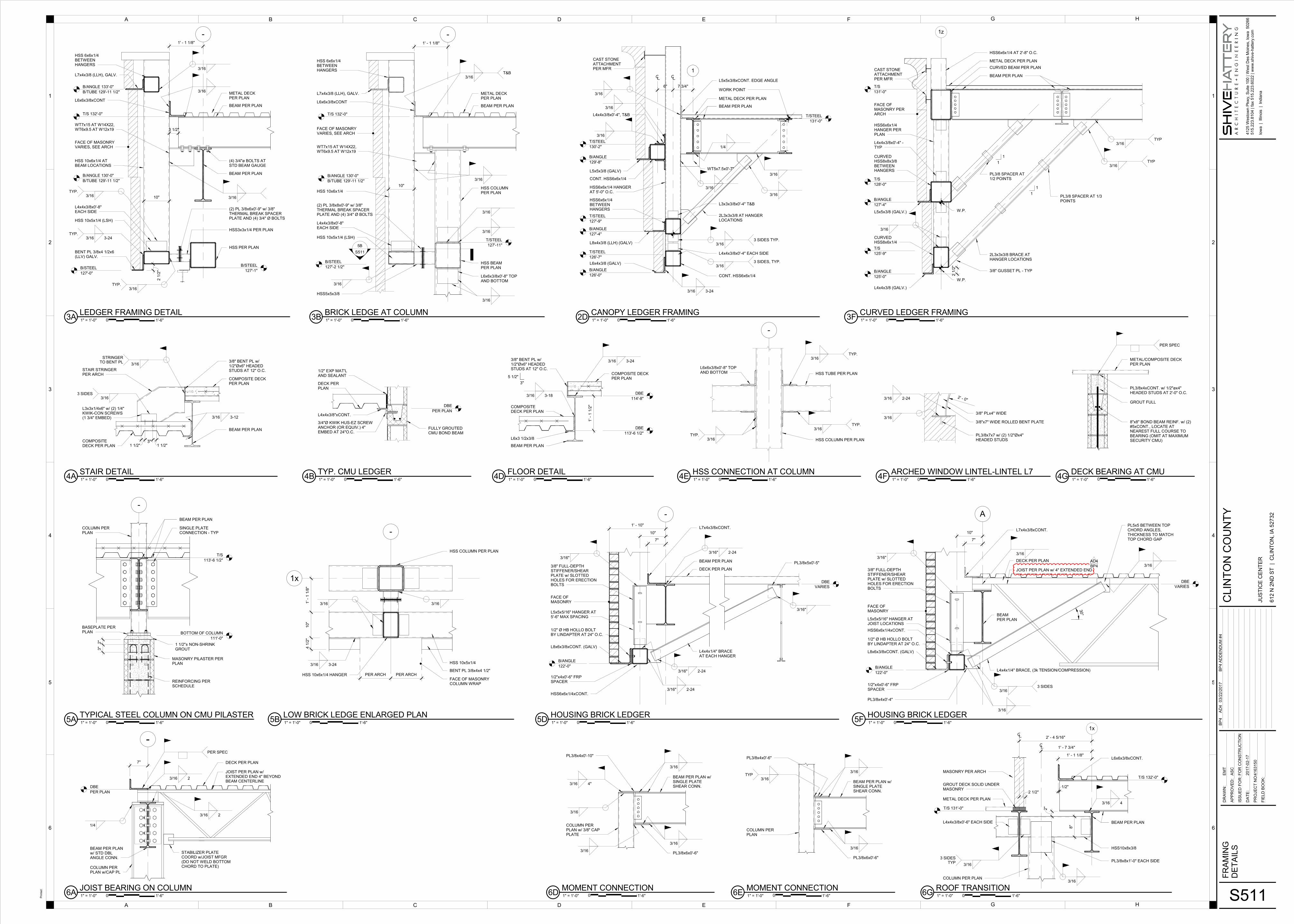
BENT PL 3/8x4 1/2x6 (LLV) GALV.
HSS 10x5x1/4 (LSH)
HSS3x3x1/4 PER PLAN
FACE OF MASONRY VARIES, SEE ARCH
HSS PER PLAN
B/STEEL
127'-0"
T/S 132'-0"
BEAM PER PLAN
BEAM PER PLAN
1' - 1 1/8"
METAL DECK PER PLAN
(4) 3/4"ø BOLTS AT STD BEAM GAUGE
-
3 1/2"
HSS 6x6x1/4 BETWEEN HANGERS
L7x4x3/8 (LLH), GALV.
B/ANGLE 130'-0"
B/TUBE 129'-11 1/2"
B/STEEL
127'-1"
L6x6x3/8xCONT
HSS 10x6x1/4 AT BEAM LOCATIONS
(2) PL 3/8x6x0'-9" w/ 3/8" THERMAL BREAK SPACER PLATE AND (4) 3/4" Ø BOLTS
WT7x15 AT W14X22,WT6x9.5 AT W12x19
3/16
3/16TYP.
3/16 3-24TYP.
3/16
B/ANGLE 133'-0"
B/TUBE 129'-11 1/2"
L4x4x3/8x0'-8" EACH SIDE
3/16TYP.
3/16
2 1
/2"
10"
2"
3"
1 1/2"± NON-SHRINK GROUT
MASONRY PILASTER PER PLAN
REINFORCING PER SCHEDULE
SINGLE PLATE CONNECTION - TYP
BEAM PER PLAN
COLUMN PER PLAN
BASEPLATE PER PLAN
-
BOTTOM OF COLUMN
111'-0"
T/S
113'-6 1/2"
FULLY GROUTED CMU BOND BEAM
L4x4x3/8"xCONT.
DECK PER PLAN
1/2" EXP MAT'L AND SEALANT
DBE
PER PLAN
3/4"Ø KWIK HUS-EZ SCREW ANCHOR (OR EQUIV.) 4" EMBED AT 24"O.C.
1' -
1 1
/2"
BEAM PER PLAN
COMPOSITE DECK PER PLAN
DBE
114'-8"
DBE
113'-6 1/2"
L6x3 1/2x3/8
3/16 3-18
3/8" BENT PL w/ 1/2"Øx6" HEADED STUDS AT 12" O.C.
5 1/2"
3"
3/16 3-24
COMPOSITE DECKPER PLAN
BEAM PER PLAN
COMPOSITE DECK PER PLAN
3/8" BENT PL w/ 1/2"Øx6" HEADED STUDS AT 12" O.C.
COMPOSITE DECKPER PLAN
1 1/2"3"
1 1/2"
L3x3x1/4x6" w/ (2) 1/4" KWIK-CON SCREWS (1 3/4" EMBED)
3/163 SIDES
STAIR STRINGER PER ARCH
3/16
STRINGERTO BENT PL
3/16 3-12
1
B/ANGLE
129'-8"
T/STEEL
130'-2"
B/ANGLE
127'-4"
T/STEEL
127'-9"
B/ANGLE
126'-0"
T/STEEL
126'-7"
6" 7 3/4"
L5x5x3/8 (GALV)
CONT. HSS6x6x1/4
HSS6x6x1/4 HANGER AT 5'-0" O.C.
HSS6x6x1/4 BETWEEN HANGERS
L8x4x3/8 (LLH) (GALV)
L6x4x3/8 (GALV)
CONT. HSS6x6x1/4
2L3x3x3/8 AT HANGER LOCATIONS
BEAM PER PLAN
METAL DECK PER PLAN
WORK POINT
3/16
3/16
L4x4x3/8x0'-4", T&B
3/16
3/16
3/16 3-24
L4x4x3/8x0'-4" EACH SIDE
3/163 SIDES TYP.
3/163 SIDES, TYP.
L3x3x3/8x0'-4" T&B
T/STEEL
131'-0"
WT5x7.5x0'-7"
3/16
1/4
L5x5x3/8xCONT. EDGE ANGLE
3/16
CAST STONE ATTACHMENT PER MFR
1
1
1
1
B/ANGLE
127'-4"
B/ANGLE
125'-0"
T/S
125'-9"
T/S
128'-0"
T/S
131'-0"
L4x4x3/8 (GALV.)
CURVED HSS8x6x1/4
L5x5x3/8 (GALV.)
CURVED HSS8x8x3/8 BETWEEN HANGERS
HSS6x6x1/4 HANGER PER PLAN
W.P.
W.P.
FACE OF MASONRY PER ARCH
BEAM PER PLAN
METAL DECK PER PLAN
2L3x3x3/8 BRACE AT HANGER LOCATIONS
3/8" GUSSET PL - TYP
3/16
3/16TYP
3/16TYP
PL3/8 SPACER AT 1/3 POINTS
PL3/8 SPACER AT 1/2 POINTS
L4x4x3/8x0'-4" -TYP
1z
CURVED BEAM PER PLAN
2 1
/2"
HSS6x6x1/4 AT 2'-8" O.C.
CAST STONE ATTACHMENT PER MFR
HSS 10x5x1/4 (LSH)
FACE OF MASONRY VARIES, SEE ARCH
HSS BEAM PER PLAN
B/STEEL
127'-2 1/2"
T/S 132'-0"
BEAM PER PLAN
1' - 1 1/8"
METAL DECK PER PLAN
-
B/ANGLE 130'-0"
B/TUBE 129'-11 1/2"
T/STEEL
127'-11"
L6x6x3/8xCONT
HSS5x5x3/8
HSS COLUMN PER PLAN
5B
S511
3/16T&B
3/16
3/16
WT7x15 AT W14X22,WT6x9.5 AT W12x19
HSS 6x6x1/4 BETWEEN HANGERS
L7x4x3/8 (LLH), GALV.
HSS 10x6x1/4
3/16
3/16
L6x6x3/8x0'-8" TOP AND BOTTOM
(2) PL 3/8x8x0'-9" w/ 3/8" THERMAL BREAK SPACER PLATE AND (4) 3/4" Ø BOLTS
10"
L4x4x3/8x0'-8" EACH SIDE
3/16
1' -
1 1
/8"
10"
4 1
/2"
PER ARCH PER ARCH
3/16 3-24
3/163/16
1x
-
HSS 10x5x1/4
HSS 10x6x1/4 HANGER
HSS COLUMN PER PLAN
BENT PL 3/8x4x4 1/2"
FACE OF MASONRYCOLUMN WRAP
PL3/8x4xCONT. w/ 1/2"øx4" HEADED STUDS AT 2'-0" O.C.
8"x8" BOND BEAM REINF. w/ (2) #5xCONT., LOCATE AT NEAREST FULL COURSE TO BEARING (OMIT AT MAXIMUM SECURITY CMU)
METAL/COMPOSITE DECK PER PLAN
GROUT FULL
PER SPEC
-
DECK PER PLAN
7"
L7x4x3/8xCONT.
FACE OF MASONRY
1/2"x4x0'-6" FRP SPACER
L8x6x3/8xCONT. (GALV)
B/ANGLE
122'-0"
L5x5x5/16" HANGER AT 5'-6" MAX SPACING
1/2" Ø HB HOLLO BOLTBY LINDAPTER AT 24" O.C.
HSS6x6x1/4xCONT.
1' - 10"
10"
BEAM PER PLAN
L4x4x1/4" BRACEAT EACH HANGER
3/16"
3/8" FULL-DEPTHSTIFFENER/SHEARPLATE w/ SLOTTEDHOLES FOR ERECTIONBOLTS
3/16"
DBE
VARIES
PL3/8x5x0'-5"
3/16" 2-24
3/16" 2-24
3/16" 2-24
A
DECK PER PLAN
7"
L7x4x3/8xCONT.
FACE OF MASONRY
1/2"x4x0'-6" FRP SPACER
L8x6x3/8xCONT. (GALV)
B/ANGLE
122'-0"
L5x5x5/16" HANGER AT JOIST LOCATIONS
1/2" Ø HB HOLLO BOLTBY LINDAPTER AT 24" O.C.
HSS6x6x1/4xCONT.
10"
BEAM PER PLAN
L4x4x1/4" BRACE, (3k TENSION/COMPRESSION)
3/8" FULL-DEPTHSTIFFENER/SHEARPLATE w/ SLOTTEDHOLES FOR ERECTIONBOLTS
3/16"
DBE
VARIES
3/16
PL5x5 BETWEEN TOP CHORD ANGLES, THICKNESS TO MATCH TOP CHORD GAP
3/163 SIDES
3/16
JOIST PER PLAN w/ 4" EXTENDED END
3/16
PL3/8x4x0'-4"
30°
AD4
BP4
3/16
BEAM PER PLAN w/ SINGLE PLATE SHEAR CONN.
PL3/8x4x0'-10"
3/16
PL3/8x6x0'-6"3/16
3/16 4"
COLUMN PER PLAN w/ 3/8" CAP PLATE
3/16
3/16
BEAM PER PLAN w/ SINGLE PLATE SHEAR CONN.
PL3/8x4x0'-6"
3/16
PL3/8x6x0'-6"
3/16TYP
COLUMN PER PLAN
1' - 1 1/8"
1/2"
2 1/2"
1' - 7 3/4"
2' - 4 5/16"
1x
2"T/S 131'-0"
T/S 132'-0"
L4x4x3/8x0'-6" EACH SIDE
3/16
3 SIDESTYP
COLUMN PER PLAN
METAL DECK PER PLAN
GROUT DECK SOLID UNDER MASONRY
MASONRY PER ARCH
L6x6x3/8xCONT.
BEAM PER PLAN
HSS10x8x3/8
PL3/8x8x1'-0" EACH SIDE
3/16
3/16 4
8"
-
HSS TUBE PER PLAN
HSS COLUMN PER PLAN
L6x6x3/8x0'-8" TOP AND BOTTOM
3/16TYP.
3/16TYP.
3/16TYP.
-
7"
DBE
PER PLAN
BEAM PER PLAN w/ STD DBL ANGLE CONN.
1/4
COLUMN PER PLAN w/CAP PL
PER SPEC
3/16 2
3/16 2
DECK PER PLAN
JOIST PER PLAN w/ EXTENDED END 4" BEYOND BEAM CENTERLINE
STABILIZER PLATE COORD w/JOIST MFGR (DO NOT WELD BOTTOM CHORD TO PLATE)
3/8"x7" WIDE ROLLED BENT PLATE
2' - 0"
3/8" PLx4" WIDE
PL3/8x7x7 w/ (2) 1/2"Øx4" HEADED STUDS
3/16 2-24
3/16
4125 W
esto
wn P
kw
y, S
uite 1
00 | W
est D
es M
oin
es, Io
wa 50266
515.2
23.8
104 | fax 5
15.2
23.6
022 | w
ww
.shiv
e-h
attery
.com
6
5
4
3
BA D E
1
FC G
2
Iow
a | Illi
nois
| India
na
DR
AW
N:
AP
PR
OV
ED
:
ISS
UE
D F
OR
:
DA
TE
:
FIE
LD
BO
OK
:
PR
OJE
CT
NO
:
H
BA D E FC G H
6
5
4
3
1
2
Printe
d:
CLIN
TO
N C
OU
NT
Y
JU
ST
ICE
CE
NT
ER
612
N 2
ND
ST
| C
LIN
TO
N, IA
527
32
S511
FR
AM
ING
DE
TA
ILS
FO
R C
ON
ST
RU
CT
ION
41
63
15
0
AS
C
EM
T
20
17
-02
-17
0 1" = 1'-0"3ALEDGER FRAMING DETAIL
1'-6"
0 1" = 1'-0"5ATYPICAL STEEL COLUMN ON CMU PILASTER
1'-6"
0 1" = 1'-0"4BTYP. CMU LEDGER
1'-6" 0 1" = 1'-0"4DFLOOR DETAIL
1'-6"0 1" = 1'-0"4ASTAIR DETAIL
1'-6"
0 1" = 1'-0"2DCANOPY LEDGER FRAMING
1'-6" 0 1" = 1'-0"3FCURVED LEDGER FRAMING
1'-6"0 1" = 1'-0"3BBRICK LEDGE AT COLUMN
1'-6"
0 1" = 1'-0"5BLOW BRICK LEDGE ENLARGED PLAN
1'-6"
0 1" = 1'-0"4GDECK BEARING AT CMU
1'-6"
0 1" = 1'-0"5DHOUSING BRICK LEDGER
1'-6" 0 1" = 1'-0"5FHOUSING BRICK LEDGER
1'-6"
0 1" = 1'-0"6DMOMENT CONNECTION
1'-6" 0 1" = 1'-0"6EMOMENT CONNECTION
1'-6" 0 1" = 1'-0"6GROOF TRANSITION
1'-6"
BP
4A
D4
03
/22
/20
17
BP
4 A
DD
EN
DU
M #
4
0 1" = 1'-0"4EHSS CONNECTION AT COLUMN
1'-6"
0 1" = 1'-0"6AJOIST BEARING ON COLUMN
1'-6"
0 1" = 1'-0"4FARCHED WINDOW LINTEL-LINTEL L7
1'-6"

L3x3x1/4
3/16 2"
3/162 SIDES
VARIES
GUSSET PL 3/8", TYP
BEAM PER PLAN
DBE
PER PLAN
(TYP.)1 1/2"
5 1/2"
1 1/2" (TYP.)
COLUMN PER PLAN
PL 3/4x8 1/2x1'-0"
(4) 3/4"Ø A325 BOLT
1/4
BEAM PER PLAN, BELOW
6"
6"
8
2y
1' - 0"
COLUMN PER PLAN
BASE PL PER PLAN(SHIM LEVEL)
BDE
PER PLAN
3/8" STIFFENER PL FULL DEPTH CENTERED UNDER COLUMN
BEAM PER PLAN
COMPOSITE DECKPER PLAN
POUR STOP
1/2" EXPLANATIONMATERIAL
CONCRETE INFILL
NOTE: INSTALL COLUMN AFTER FLOOR DEAD LOADS ARE IN PLACE (INCLUDING ADJACENT EXTERIOR 2ND FLOOR WALL w/ METAL STUDS & BRICK)
3A
S512
CMU WALL
STEEL BEAMPER PLAN
SEE TYPICAL BEAM BEARING ON CMU DETAIL FOR MORE INFO
SEE DECK BEARING AT CMU DETAIL FOR MORE INFO
CMU WALL BEYOND FILL AND GROUT SOLID AROUND BEAM
2.2
ANGLE BRACE
ANGLE BRACE
1' - 0" 1' - 0"
COLUMN PER 2ND FL PLAN
W33x118
L3x3x1/4 BRACE
2A
S512
2A
S512
SIM
A
A
BASE PL PER 2ND FL PLAN
E
VARIES
SECTION A-A
BEAM PER PLAN
STIFFENER PL
SEE SHEAR CONNECTION AT GIRDER FOR MORE INFO.
INFILL WITH 5 1/2" CONCRETEAFTER COLUMN INSTALLATION
CMU ELEVATOR SHAFT WALL
FILLER PL
POUR STOP
FLOOR SLAB PER PLAN
CAP PL 1"x11"x1'-2"w/ (4) 3/4" BOLTS
3/163 SIDES, TYP
SEE SHEAR CONNECTION AT GIRDER FOR MORE INFO.
COPE STIFFENER PL
1/4
STIFFENER PL
1 1/2"
11" 1 1/2"
3" 5 1/2" 3"
3/162 SIDES
NOTE: INSTALL 2ND LEVEL COLUMN AFTER FLOOR DEAD LOADS ARE IN PLACE (INCLUDING LOBBY STAIR CASE)
3 3/4"
4 3/4"
10 1/4"
-
METAL DECK PER PLAN
BEAM PER PLAN
L5x5x3/8xCONT. EDGE ANGLE
PL3/8x8 1/2x1'-2" w/(4) 3/4"ø BOLTS AT STD BEAM GAUGE
3/16
HSS COLUMN PER PLAN
L4x4x1/4x0'-5" T&B, TYP.
T/STEEL
131'-0"
3/16TYP
3/16TYP
3/16TYP
3 SIDES
L4x4x3/8x0'-8" EACH SIDE
GRINDSMOOTHEXPOSEDWELDS, TYP
BUILT UP CENTERSTRINGER (3) HSS14x4x3/8
PL3/8x4x0'-8"BOTH SIDES
1/4" CAP PL
RAILING BALUSTER PER ARCH
HSS 8x2x3/16xOUT RIGGER
TREAD SURFACE PER ARCH
1/4" TRIANGULAR FILLER PL
BALUSTER TOCAP PL
A
A
NOTE: STEEL IS ARCH EXPOSED.SEE ARCH DWGS & SPEC FOR MORE INFO
CONCRETE w/ TERRAZZO PER ARCH
HSS8x2x3/16xLENGTH PER ARCH
BUILT UP STRINGER
6 1/2" +/-
3/163 SIDES
3/16
PL TOSTRINGER
3/16TYP.
ELEVATION A-A
SEE ARCH FOR EXACT TREAD HEIGHT
7"
3/16
GRINDSMOOTH, TYP
1"
6' - 0"
5"
PL 1/4 TREAD, SEE ARCH
-
4 3/4"
3/16
PL 3/8x8 1/2x1'-2" w/ (4) 3/4"Ø BOLTS AT STD BEAM GAUGE
T/STEEL
131'-0"
3/16
3/1610 1/4"
PL 3/8x5x1'-2"
EDGE ANGLE BEYOND
1' - 3"
1x 1.1x
T/STEEL
127'-4"
3/16
BEAM PER PLAN
METAL DECK PER PLAN
HSS4x4x1/4
L4x4x3/8 EDGE ANGLE
LEDGER FRAMING PER DETAILS
T/TUBE
113'-6 1/2"
5"
HSS4x4x1/4
3/16TYP.
HSS COLUMN PER PLAN
3 5/8"
T/STEEL
127'-4"
BEAM PER PLAN
3/16
HSS3x3x1/4 AT PERP. BEAM LOCATIONS
1.1x
6"
3 5/8"
FACE OF STUD 3/16
L4x4x3/8xCONT
L4x4x3/8 FOR CURTAIN WALL ATTACHMENT
CURTAIN WALL PER ARCH
3 1/2"
1' - 1 1/8"
1x
X H
1' - 0"
3/16TYP.
3/8" PLATES PER SCHEDULE w/ 3/8" THERMAL BREAK PLATE w/ (4) 3/4"Ø BOLTS
BEAM
W18x35
W21x44
HEIGHT (H) WIDTH (W) BOLT SPACING (X)
PLATE
24"
27"
6 1/2"
7"
21"
24"
L8x6x7/16xCONT
WT6x9.5
3/16
3/16
1" MIN, 3" MAX
SLAB OR DECK PER PLAN (ORIENTATION VARIES)
BENT PLATE 12GAx6"x6"xCONT (BOTH SIDES), INSTALL TIGHT TO FACE OF CMU
INTERIOR NON LOAD BRG CMU WALL, COORDINATE LOCATION w/ ARCH
D.B.E.
PER PLAN
#12 SCREW x1" LONG AT 6" O.C. IN BOTTOM OF DECK FLUTE
8" BOND BEAM w/ (2) #5 CONT.
3" DEFLECTION ALLOWANCE
FLOOR SLAB PER PLAN
BEAM PER PLAN
BENT PL 12GAx6x6xCONT (BOTH SIDES) INSTALL TIGHT TO FACE OF CMU
INTERIOR NON LOAD BRG CMU WALL, COORDINATE LOCATION w/ ARCH
3/16 4TYP.
D.B.E.
PER PLAN
T/WALL
VARIES
8" BOND BEAM w/ (2) #5 CONT.
FLOOR SLAB PER PLAN
BEAM PER PLAN
(2) CONT. BENT PLATES ATTACH TO TOP AND/OR BOTTOM OF BOTTOM FLANGE AS REQ'D
INTERIOR NON LOAD BRG CMU WALL COORDINATE LOCATION w/ ARCH
D.B.E
PER PLAN
T/WALL
VARIES
3" DEFLECTION ALLOWANCE
1/8 3-24TYP.
1/8 3-24TYP.
8" BOND BEAM w/ (2) #5 CONT.
A
DECK PER PLAN
7"L7x4x3/8xCONT.
FACE OF MASONRY
1/2"x4x0'-6" FRP SPACER
L8x6x3/8xCONT. (GALV)
B/ANGLE
122'-0"
1/2" Ø HB HOLLO BOLTBY LINDAPTER AT 24" O.C.
HSS PER PLAN
BEAM PER PLAN
L4x4x1/4" BRACE
(2) 3/4"ø BOLTS
3/163 SIDES
DBE
VARIES
JOIST PER PLAN w/ 4" EXTENDED END
3/16
45°
6"
PL3/8x10x1'-0"
3/8" FULL DEPTH STIFFENER SHEAR PLATE w/ VERTICAL LONG SLOTTED HOLES
1' - 10"
T/WALL
118'-0"
3/16
PL3/8x7x0'-7" w/(2) 1/2"ø HEADED STUDS AT 4" SPACING
(2) #5 BARS xCONT.
AD4
BP4
4125 Westown Pkwy, Suite 100 | West Des Moines, Iowa 50266
515.223.8104 | fax 515.223.6022 | www.shive-hattery.com
6
5
4
3
BA D E
1
FC G
2
Iowa | Illinois | Indiana
DRAWN:
APPROVED:
ISSUED FOR:
DATE:
FIELD BOOK:
PROJECT NO:
H
BA D E FC G H
6
5
4
3
1
2
Printed:
CLINTON COUNTY
JUSTICE CENTER
612 N 2ND ST | CLINTON, IA 52732
S512
FRAMING
DETAILS
FOR CONSTRUCTION
4163150
Approver
Author
2017-02-17
0 1" = 1'-0"2ABOTTOM FLANGE BRACE
1'-6"
0 1" = 1'-0"3ABP5
1'-6"
0 1" = 1'-0"4ACOLUMN OVER BEAM
1'-6" 0 1" = 1'-0"4BTYPICAL CANTILEVER BEAM OVER CMU WALL
1'-6"
0 1" = 1'-0"6AW33x118 TRHOUGH COLUMN E-2.2
1'-6"
0 1" = 1'-0"3GCANOPY LEDGER AT COLUMN
1'-6"
0 1" = 1'-0"6CLOBBY STAIR CASE DETAILS
1'-6"
0 1" = 1'-0"4DCANOPY MOMENT CONNECTION
1'-6"
0 1" = 1'-0"3ECOLUMN DETAIL
1'-6"0 1" = 1'-0"3BEDGE OF LOW ROOF
1'-6" 0 1" = 1'-0"3DBEAM THERMAL BREAK
1'-6"
0 1" = 1'-0"2B
NON LOAD BRG CMU WALL AT BOTTOM OF DECK,TYPICAL
1'-6"
0 1" = 1'-0"4G
NON LOAD BRD CMU WALL AT BOTTOM OF STEELBEAM (PERPENDICULAR), TYPICAL
1'-6"0 1" = 1'-0"4E
NON LOAD BRG CMU WALL AT BOTTOM OF STEELBEAM (PARALLEL), TYPICAL
1'-6"
BP4
AD403/22/2017
BP4 ADDENDUM #4
0 1" = 1'-0"6FPOST AT COILING DOOR
1'-6"
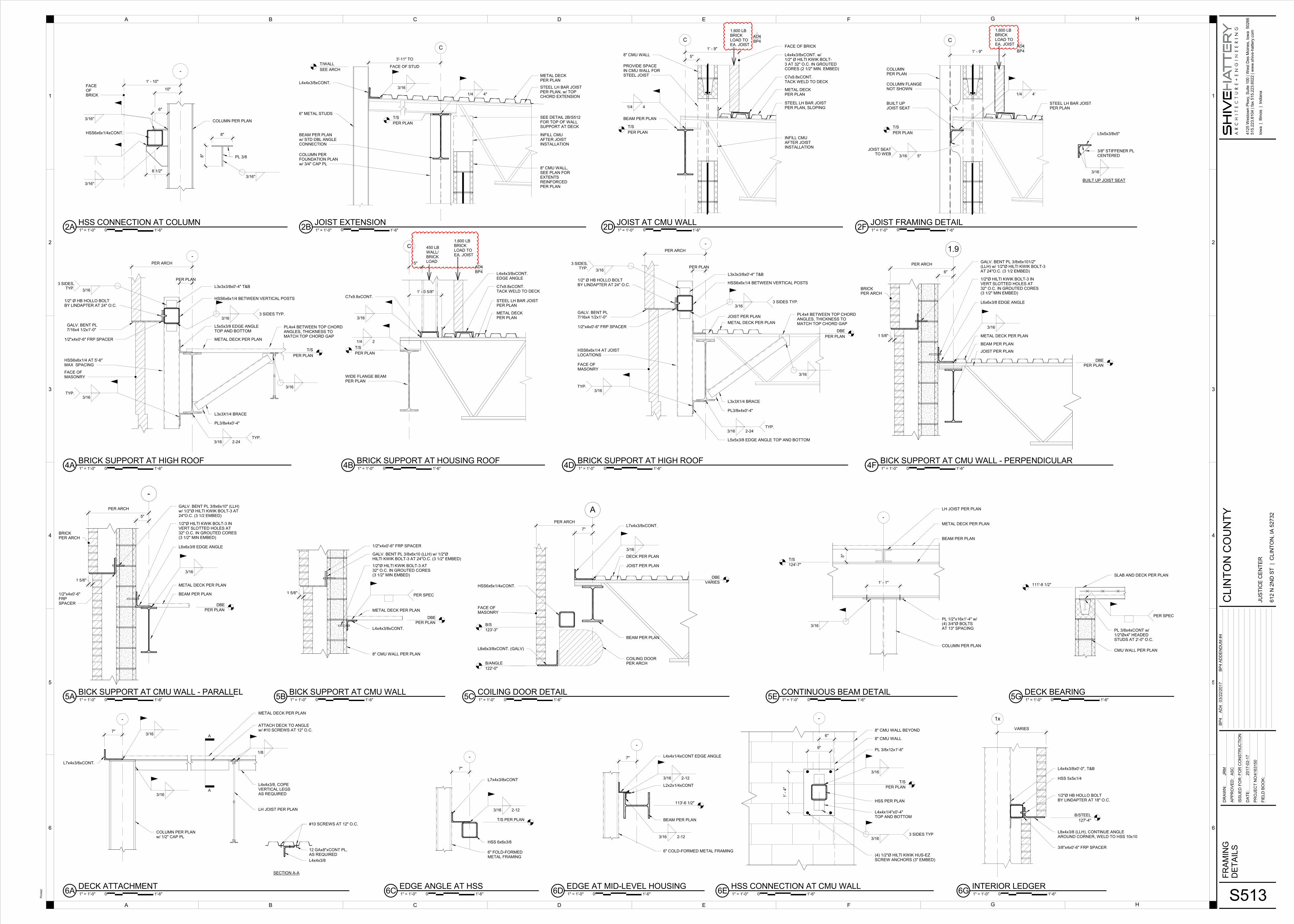
1' - 10"
-
FACE OFBRICK
COLUMN PER PLAN
8"
8"
PL 3/8
3/16"
3/16"
3/16"
HSS6x6x1/4xCONT.
10"
8 1/2"
6"
C
T/WALL
SEE ARCH
T/S
PER PLAN
FACE OF STUD
3'-11" TO
6" METAL STUDS
L4x4x3/8xCONT.3/16
BEAM PER PLANw/ STD DBL ANGLE CONNECTION
COLUMN PER FOUNDATION PLAN w/ 3/4" CAP PL
1/4 4"
STEEL LH BAR JOISTPER PLAN, w/ TOP CHORD EXTENSION
METAL DECK PER PLAN
INFILL CMU AFTER JOIST INSTALLATION
8" CMU WALL, SEE PLAN FOR EXTENTSREINFORCED PER PLAN
SEE DETAIL 2B/S512FOR TOP OF WALL SUPPORT AT DECK
C
L4x4x3/8xCONT. w/ 1/2" Ø HILTI KWIK BOLT-3 AT 32" O.C. IN GROUTED CORES (2 1/2" MIN. EMBED)
STEEL LH BAR JOISTPER PLAN, SLOPING
METAL DECK PER PLAN
C7x9.8xCONT.TACK WELD TO DECK
FACE OF BRICK
8" CMU WALL 5"
BEAM PER PLAN
PROVIDE SPACE IN CMU WALL FOR STEEL JOIST
1/4 4
T/S
PER PLAN
1,600 LB BRICK LOAD TO EA. JOIST
1' - 9"
INFILL CMUAFTER JOISTINSTALLATION
AD4
BP4 C
STEEL LH BAR JOISTPER PLAN
T/S
PER PLAN
BUILT UPJOIST SEAT
BUILT UP JOIST SEAT
L5x5x3/8x5"
3/8" STIFFENER PLCENTERED
3/16
COLUMN FLANGE NOT SHOWN
COLUMNPER PLAN
3/16 5"
JOIST SEATTO WEB
1,600 LB BRICK LOAD TO EA. JOIST
1' - 9"
1/4 4'
AD4
BP4
FACE OF MASONRY
1/2"x4x0'-6" FRP SPACER
-
PER PLAN
PER ARCH
GALV. BENT PL 7/16x4 1/2x1'-0"
1/2" Ø HB HOLLO BOLTBY LINDAPTER AT 24" O.C.
T/S
PER PLAN
METAL DECK PER PLAN
L5x5x3/8 EDGE ANGLE TOP AND BOTTOM
3/16TYP.
3/16 2-24TYP.
HSS6x6x1/4 AT 5'-6" MAX SPACING
HSS6x6x1/4 BETWEEN VERTICAL POSTS
3/163 SIDES TYP.
3/16
3 SIDES,TYP. L3x3x3/8x0'-4" T&B
PL4x4 BETWEEN TOP CHORD ANGLES, THICKNESS TO MATCH TOP CHORD GAP
L3x3X1/4 BRACE
PL3/8x4x0'-4"
3/16
T/S
PER PLAN
C
5"
L4x4x3/8xCONT. EDGE ANGLE
STEEL LH BAR JOISTPER PLAN
METAL DECK PER PLAN
C7x9.8xCONT.TACK WELD TO DECK
C7x9.8xCONT.
WIDE FLANGE BEAM PER PLAN
1' - 0 5/8"
3/16
1/4 2
1,600 LB BRICK LOAD TO EA. JOIST
450 LB WALL/BRICKLOAD
FACE OF MASONRY
1/2"x4x0'-6" FRP SPACER
-
PER PLAN
PER ARCH
GALV. BENT PL 7/16x4 1/2x1'-0"
1/2" Ø HB HOLLO BOLTBY LINDAPTER AT 24" O.C.
DBE
PER PLAN
METAL DECK PER PLAN
L5x5x3/8 EDGE ANGLE TOP AND BOTTOM
3/16TYP.
3/16 2-24TYP.
JOIST PER PLAN
HSS6x6x1/4 AT JOIST LOCATIONS
HSS6x6x1/4 BETWEEN VERTICAL POSTS
3/163 SIDES TYP.
3/16
3 SIDES,TYP.
L3x3x3/8x0'-4" T&B
PL4x4 BETWEEN TOP CHORD ANGLES, THICKNESS TO MATCH TOP CHORD GAP
L3x3X1/4 BRACE
PL3/8x4x0'-4"
3/16
DBE
PER PLAN
1 5/8"
GALV. BENT PL 3/8x6x10 (LLH) w/ 1/2"ØHILTI KWIK BOLT-3 AT 24"O.C. (3 1/2" EMBED)
L4x4x3/8xCONT.
8" CMU WALL PER PLAN
METAL DECK PER PLAN
PER SPEC
1/2"Ø HILTI KWIK BOLT-3 AT 32" O.C. IN GROUTED CORES (3 1/2" MIN EMBED)
1/2"x4x0'-6" FRP SPACER
-
5"
DBE
PER PLAN
PER ARCH
1 5/8"
BRICKPER ARCH
1/2"Ø HILTI KWIK BOLT-3 IN VERT SLOTTED HOLES AT 32" O.C. IN GROUTED CORES (3 1/2" MIN EMBED)
L6x6x3/8 EDGE ANGLE
GALV. BENT PL 3/8x6x10" (LLH) w/ 1/2"Ø HILTI KWIK BOLT-3 AT 24"O.C. (3 1/2 EMBED)
3/16
METAL DECK PER PLAN
BEAM PER PLAN1/2"x4x0'-6" FRP SPACER
1.9
6"
DBE
PER PLAN
PER ARCH
1 5/8"
BRICKPER ARCH
1/2"Ø HILTI KWIK BOLT-3 IN VERT SLOTTED HOLES AT 32" O.C. IN GROUTED CORES (3 1/2" MIN EMBED)
L6x6x3/8 EDGE ANGLE
GALV. BENT PL 3/8x6x101/2" (LLH) w/ 1/2"Ø HILTI KWIK BOLT-3 AT 24"O.C. (3 1/2 EMBED)
3/16
METAL DECK PER PLAN
JOIST PER PLAN
BEAM PER PLAN
A
DECK PER PLAN
7"L7x4x3/8xCONT.
FACE OF MASONRY
L8x6x3/8xCONT. (GALV)
B/ANGLE
122'-0"
DBE
VARIES
JOIST PER PLAN
3/16
PER ARCH
B/S
123'-3"
HSS6x6x1/4xCONT.
BEAM PER PLAN
COILING DOOR PER ARCH
5"
1' - 1"
-
T/S
124'-7"
3/16
LH JOIST PER PLAN
METAL DECK PER PLAN
BEAM PER PLAN
PL 1/2"x16x1'-4" w/(4) 3/4"Ø BOLTS AT 13" SPACING
COLUMN PER PLAN
7"
-
3/16
3/16
SECTION A-A
A
A
L7x4x3/8xCONT.
METAL DECK PER PLAN
ATTACH DECK TO ANGLE w/ #10 SCREWS AT 12" O.C.
1/8
L4x4x3/8, COPE VERTICAL LEGS AS REQUIRED
LH JOIST PER PLAN
COLUMN PER PLAN w/ 1/2" CAP PL
#10 SCREWS AT 12" O.C.
12 GAx8"xCONT PL, AS REQUIRED
L4x4x3/8
111'-8 1/2"
PER SPEC
SLAB AND DECK PER PLAN
PL 3/8x4xCONT w/ 1/2"Øx4" HEADED STUDS AT 2'-0" O.C.
CMU WALL PER PLAN
7"
-
T/S PER PLAN
3/16 2-12
6" FOLD-FORMED METAL FRAMING
HSS 6x6x3/8
L7x4x3/8xCONT
113'-6 1/2"
7"
-
6" COLD-FORMED METAL FRAMING
L4x4x1/4xCONT EDGE ANGLE
L2x2x1/4xCONT
3/16 2-12
BEAM PER PLAN
3/16 2-12
1' - 4"
6"
9"
-
3/163 SIDES TYP
T/S
PER PLAN
PL 3/8x12x1'-6"
8" CMU WALL
HSS PER PLAN
L4x4x1/4"x0'-4" TOP AND BOTTOM
(4) 1/2"Ø HILTI KWIK HUS-EZ SCREW ANCHORS (3" EMBED)
8" CMU WALL BEYOND
3/16
VARIES
1x
B/STEEL
127'-4"
HSS 5x5x1/4
L4x4x3/8x0'-0", T&B
1/2"Ø HB HOLLO BOLTBY LINDAPTER AT 18" O.C.
L8x4x3/8 (LLH), CONTINUE ANGLE AROUND CORNER, WELD TO HSS 10x10
3/8"x4x0'-6" FRP SPACER
4125 Westown Pkwy, Suite 100 | West Des Moines, Iowa 50266
515.223.8104 | fax 515.223.6022 | www.shive-hattery.com
6
5
4
3
BA D E
1
FC G
2
Iowa | Illinois | Indiana
DRAWN:
APPROVED:
ISSUED FOR:
DATE:
FIELD BOOK:
PROJECT NO:
H
BA D E FC G H
6
5
4
3
1
2
Printed:
CLINTON COUNTY
JUSTICE CENTER
612 N 2ND ST | CLINTON, IA 52732
S513
FRAMING
DETAILS
FOR CONSTRUCTION
4163150
ASC
JRM
2017-02-17
BP4AD403/22/2017
BP4 ADDENDUM #4
0 1" = 1'-0"2AHSS CONNECTION AT COLUMN
1'-6" 0 1" = 1'-0"2BJOIST EXTENSION
1'-6" 0 1" = 1'-0"2DJOIST AT CMU WALL
1'-6" 0 1" = 1'-0"2FJOIST FRAMING DETAIL
1'-6"
0 1" = 1'-0"4ABRICK SUPPORT AT HIGH ROOF
1'-6" 0 1" = 1'-0"4BBRICK SUPPORT AT HOUSING ROOF
1'-6" 0 1" = 1'-0"4DBRICK SUPPORT AT HIGH ROOF
1'-6"
0 1" = 1'-0"5BBICK SUPPORT AT CMU WALL
1'-6"0 1" = 1'-0"5ABICK SUPPORT AT CMU WALL - PARALLEL
1'-6"
0 1" = 1'-0"4FBICK SUPPORT AT CMU WALL - PERPENDICULAR
1'-6"
0 1" = 1'-0"5CCOILING DOOR DETAIL
1'-6" 0 1" = 1'-0"5ECONTINUOUS BEAM DETAIL
1'-6"
0 1" = 1'-0"6ADECK ATTACHMENT
1'-6"
0 1" = 1'-0"5GDECK BEARING
1'-6"
0 1" = 1'-0"6CEDGE ANGLE AT HSS
1'-6" 0 1" = 1'-0"6DEDGE AT MID-LEVEL HOUSING
1'-6" 0 1" = 1'-0"6EHSS CONNECTION AT CMU WALL
1'-6" 0 1" = 1'-0"6GINTERIOR LEDGER
1'-6"
AD4
BP4