cladding alloys for fluoride salt compatibility final report
TRANSCRIPT

ORNL/TM-2010/319
Cladding Alloys for Fluoride Salt Compatibility Final Report
April 1, 2011
Prepared by Govindarajan Muralidharan Dane F. Wilson Larry R. Walker Michael L. Santella David E. Holcomb
DOCUMENT AVAILABILITY
Reports produced after January 1, 1996, are generally available free via the U.S. Department of Energy (DOE) Information Bridge. Web site http://www.osti.gov/bridge Reports produced before January 1, 1996, may be purchased by members of the public from the following source. National Technical Information Service 5285 Port Royal Road Springfield, VA 22161 Telephone 703-605-6000 (1-800-553-6847) TDD 703-487-4639 Fax 703-605-6900 E-mail [email protected] Web site http://www.ntis.gov/support/ordernowabout.htm Reports are available to DOE employees, DOE contractors, Energy Technology Data Exchange (ETDE) representatives, and International Nuclear Information System (INIS) representatives from the following source. Office of Scientific and Technical Information P.O. Box 62 Oak Ridge, TN 37831 Telephone 865-576-8401 Fax 865-576-5728 E-mail [email protected] Web site http://www.osti.gov/contact.html
This report was prepared as an account of work sponsored by an agency of the United States Government. Neither the United States Government nor any agency thereof, nor any of their employees, makes any warranty, express or implied, or assumes any legal liability or responsibility for the accuracy, completeness, or usefulness of any information, apparatus, product, or process disclosed, or represents that its use would not infringe privately owned rights. Reference herein to any specific commercial product, process, or service by trade name, trademark, manufacturer, or otherwise, does not necessarily constitute or imply its endorsement, recommendation, or favoring by the United States Government or any agency thereof. The views and opinions of authors expressed herein do not necessarily state or reflect those of the United States Government or any agency thereof.

ORNL/TM-2010/319
Materials Science and Technology Division
CLADDING ALLOYS FOR FLUORIDE SALT COMPATIBILITY
Govindarajan Muralidharan
Dane F. Wilson
Larry R. Walker
Michael L. Santella
David E. Holcomb
Date Published: April 1, 2011
Prepared by
OAK RIDGE NATIONAL LABORATORY
Oak Ridge, Tennessee 37831-6283
managed by
UT-BATTELLE, LLC
for the
U.S. DEPARTMENT OF ENERGY
under contract DE-AC05-00OR22725


iii
CONTENTS
Page
LIST OF FIGURES ................................................................................................................................ v LIST OF TABLES ............................................................................................................................... vii ABSTRACT .......................................................................................................................................... ix 1. INTRODUCTION .......................................................................................................................... 1 2. MOTIVATION ............................................................................................................................... 5 3. REQUIREMENTS OF CLADDING TECHNOLOGIES AND CLADDING
PROPERTIES ................................................................................................................................. 7 4. A BRIEF SURVEY OF RELEVANT CLADDING TECHNIQUES ............................................ 9
4.1 ELECTROPLATING ........................................................................................................... 9 4.2 ELECTROLESS PLATING ................................................................................................. 9 4.3 PHYSICAL VAPOR DEPOSITION—VACUUM EVAPORATION,
SPUTTERING, AND OTHER TECHNIQUES ................................................................ 10 4.4 CHEMICAL VAPOR DEPOSITION ................................................................................ 11 4.5 THERMAL SPRAY TECHNIQUES ................................................................................. 11 4.6 WELD OVERLAY, LASER CLADDING, AND RELATED TECHNIQUES ................ 12 4.7 COEXTRUSION ................................................................................................................ 13
5. PROCESSING AND EVALUATION OF NICKEL CLADDINGS ........................................... 15 5.1 SELECTION AND PROCESSING OF NICKEL CLADDINGS...................................... 15
Sample Coating .................................................................................................................. 18 5.2 OBJECTIVES OF CLADDING EVALUATIONS ........................................................... 18
6. WELDING OF NICKEL-CLAD NICKEL-BASED ALLOYS ................................................... 25 6.1 CHEMICAL COMPOSITION EFFECTS ......................................................................... 25 6.2 CLADDING INTEGRITY EFFECTS ............................................................................... 26 6.3 REMARKS ......................................................................................................................... 26
7. REFERENCES ............................................................................................................................. 27


v
LIST OF FIGURES
Fig 1. Intermediate liquid salt heat transfer loop conceptual diagram showing the salt-salt heat
exchanger and the salt-gas heat exchanger. The heated gas can then be transported for electricity
production using the Brayton cycle. ....................................................................................................... 2 Fig 2. Image of the setup used for laser processing of coatings. .......................................................... 16 Fig 3. Nickel tetracarbonyl deposition process .................................................................................... 17 Fig 4. (a) Optical image of a nickel-based alloy substrate with a nickel cladding applied using a laser-
based surface cladding technique. (b) Optical image of three nickel-based substrates coated using the
CVD nickel-carbonyl process. .............................................................................................................. 18 Fig 5. (a) Optical image of the Nickel coating processed on an Alloy 617 substrate using a laser
power of 2500W. (b) Cross-sectional optical microscopy of sample shown in (a). ............................. 19 Fig 6. . (a) Optical image of the Nickel coating processed on an Alloy 617 substrate using a laser
power of 3000W. (b) Cross-sectional opetical microscopy of sample shown in (a). ........................... 19 Fig 7. (a) Optical image of the Nickel coating processed on an Alloy 617 substrate using a laser
power of 3500W. (b) Cross-sectional optical microscopy of sample shown in (a). ............................. 20 Fig 8. (a) Optical image of the Nickel coating processed on an Alloy 617 substrate using a laser
power of 4000W. (b) Cross-sectional optical microscopy of sample shown in (a). ............................. 20 Fig 9. (a) Optical image of the Nickel coating processed on an Alloy 800H substrate using a laser
power of 2500W. (b) Cross-sectional optical microscopy of sample shown in (a). ............................. 21 Fig 10. (a) Optical image of the Nickel coating processed on an Alloy 800H substrate using a laser
power of 3000W. (b) Cross-sectional optical microscopy of sample shown in (a). ............................. 21 Fig 11. (a) Optical image of the Nickel coating processed on an Alloy 800H substrate using a laser
power of 3500W. (b) Cross-sectional optical microscopy of sample shown in (a). ............................. 22 Fig 12. (a) Optical image of the Nickel coating processed on an Alloy 800H substrate using a laser
power of 4000W. (b) Cross-sectional optical microscopy of sample shown in (a). ............................. 22 Fig 13. (a) Cross-sectional optical microscopy of Nickel coating processed on an Alloy 617 substrate
using a laser power of 2500W. (b) Measured composition profile along the line shown in (a). The
composition of the top surface is shown on the right. .......................................................................... 23 Fig 14. (a) Cross-sectional optical microscopy of Nickel coating processed on an Alloy 617 substrate
using a laser power of 4000W. (b) Measured composition profile along the line shown in (a). The
composition of the top surface is shown on the right. .......................................................................... 23 Fig 15. (a) Cross-sectional optical microscopy of Nickel coating processed on an Alloy 800H
substrate using a laser power of 2500W. (b) Measured composition profile along the line shown in
(a). The composition of the top surface is shown on the right. ............................................................ 24 Fig 16. (a) Cross-sectional optical microscopy of Nickel coating processed on an Alloy 800H
substrate using a laser power of 4000W. (b) Measured composition profile along the line shown in
(a). The composition of the top surface is shown on the right. ............................................................ 24


vii
LIST OF TABLES
Table Page
Table 1. Primary advantages and disadvantages of electroplating ........................................................ 9 Table 2. Primary advantages and disadvantages of electroless plating ................................................. 9 Table 3. Primary advantages and disadvantages of vacuum evaporation ........................................... 10 Table 4. Primary advantages and disadvantages of sputtering ............................................................ 10 Table 5. Primary advantages and disadvantages of chemical vapor deposition .................................. 11 Table 6. Primary advantages and disadvantages of thermal spray technique ...................................... 12 Table 7. Primary advantages and disadvantages of weld overlay/laser cladding techniques .............. 12 Table 8. Primary advantages and disadvantages of the coextrusion process....................................... 13 Table 9. Effects of some commonly present elements. ........................................................................ 16 Table 10. Nominal Compositions of alloy substrates used in the study. .............................................. 16 Table 11. Effects of some commonly present elements on the weldability of nickel alloys. ............... 25


ix
ABSTRACT
This report provides an overview of several candidate technologies for cladding nickel-based
corrosion protection layers onto high-temperature structural alloys. The report also provides a brief
overview of the welding and weld performance issues associated with joining nickel-clad nickel-
based alloys. From the available techniques, two cladding technologies were selected for initial
evaluation.
The first technique is a line-of-sight method that would be useful for cladding large structures such as
vessel interiors or large piping. The line-of-sight method is a laser-based surface cladding technique
in which a high-purity nickel powder mixed into a polymer binder is first sprayed onto the surface,
baked, and then rapidly melted using a high-power laser. The second technique is a vapor phase
technique based on the nickel-carbonyl process that is suitable for cladding inaccessible surfaces such
as the interior surfaces of heat exchangers.
An initial evaluation for performed on the quality of nickel claddings processed using the two
selected cladding techniques. Results show that
1.

1
1. INTRODUCTION
Heat transport systems are essential components in fluoride-salt-cooled reactors. Conceptually, the
heat transport system of a fluoride-salt-cooled high-temperature reactor (FHR) consists of two
interconnected loops. The primary loop contains the reactor core and is heated by the nuclear fission
process. The intermediate loop transfers heat from the primary loop to a secondary, electricity
generation loop. The primary loop’s fluoride salt must be both compatible with intense neutron
irradiation and an effective heat transfer medium. A review of the selection criteria for primary loop
salts was performed in 2006,1 and an analysis of the component testing requirements has recently
been published.2 The recent report includes an overview of the major plant components.
In addition to its heat transport function, the intermediate heat transport loop serves as a buffer to
prevent fuel leakage and/or induced radioactivity in the primary loop from exiting containment and
isolates the low-pressure primary system from the high-pressure electricity generation cycle. FHRs
also have a direct reactor auxiliary cooling system (DRACS), a core decay heat removal loop that
transfers heat via natural convection from the primary coolant to ambient air. The DRACS concept
was originally developed for the Experimental Breeder Reactor II and has been used in a number of
reactor designs.3 Thermal energy is transferred first from the primary coolant into the DRACS via an
in-vessel natural circulation loop and then to an external cooling loop via a natural draft heat
exchanger.
The physical configuration of the primary loop varies depending on whether the heat exchanger to the
intermediate loop is located within the primary reactor vessel. When the heat exchanger is integral to
the reactor vessel, no external piping is used and a centrifugal pump drives the fluid flow through the
primary loop. The primary-to-intermediate heat exchanger is most likely a shell-and-tube type due to
the technological maturity of that type of heat exchanger and the excellent heat transfer properties of
liquid fluoride salts.
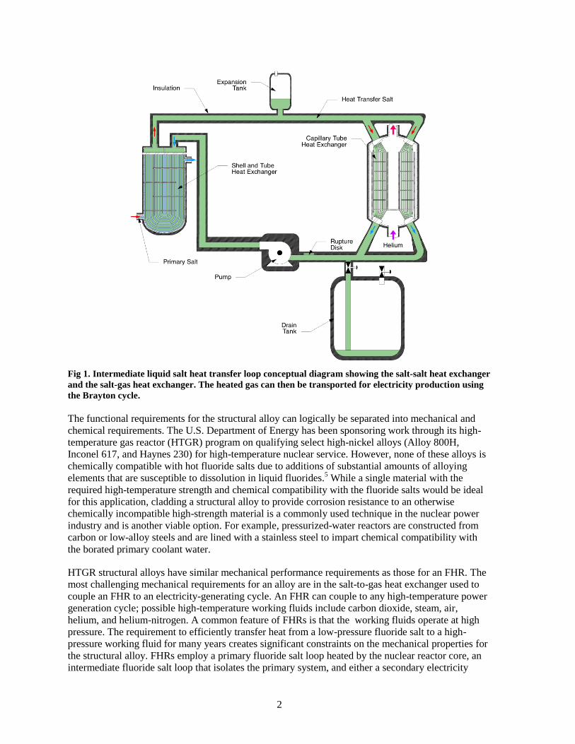
The intermediate heat transfer loop (shown conceptually in Fig 1Error! Reference source not
found.) also uses a fluoride salt as the heat transfer medium. A description and evaluation of liquid
salt heat transport technology has also recently been published.4 The intermediate heat transfer loop,
containing a single-phase, incompressible liquid, requires a void space to accommodate the expansion
of the salt and a drain tank to allow for servicing. Because the fluoride salts have melting points well
above ambient temperature, loop preheating is also required during filling of the system. Control of
the chemistry and purification of the salt is necessary in order to maintain the structural integrity of
the material surfaces that are wetted by the salt. In addition, because a liquid salt heat transfer loop
separates the liquid salt from a gas (with the gas at high pressures), sufficient physical loop length and
pressure relief mechanisms are required to prevent a severe accident (i.e., to prevent a blast wave
from propagating upstream to the reactor from the downstream conversion process for power
generation or chemical processes).
Choice of materials is critical to achieving the functionality, reliability, and targeted lifetime of FHR
structures. Even at high temperatures, nickel-based alloys embrittle under neutron radiation. Hence
nickel-based alloys are being considered only for FHR structures (including heat exchangers and
pumps) that are located outside the core. In those applications, the structural alloy requires both
mechanical strength (yield strength and creep strength) and corrosion resistance to fluoride salts, air,
and the power cycle working fluid. Also, the structural alloy needs to be reasonably formable and
joinable and not prohibitively expensive. In addition, the alloy needs to have the extensive pedigree
required for incorporation into the high-temperature nuclear section of the AMSE Boiler and Pressure
Vessel Code.
2
Fig 1. Intermediate liquid salt heat transfer loop conceptual diagram showing the salt-salt heat exchanger
and the salt-gas heat exchanger. The heated gas can then be transported for electricity production using
the Brayton cycle.
The functional requirements for the structural alloy can logically be separated into mechanical and
chemical requirements. The U.S. Department of Energy has been sponsoring work through its high-
temperature gas reactor (HTGR) program on qualifying select high-nickel alloys (Alloy 800H,
Inconel 617, and Haynes 230) for high-temperature nuclear service. However, none of these alloys is
chemically compatible with hot fluoride salts due to additions of substantial amounts of alloying
elements that are susceptible to dissolution in liquid fluorides.5 While a single material with the
required high-temperature strength and chemical compatibility with the fluoride salts would be ideal
for this application, cladding a structural alloy to provide corrosion resistance to an otherwise
chemically incompatible high-strength material is a commonly used technique in the nuclear power
industry and is another viable option. For example, pressurized-water reactors are constructed from
carbon or low-alloy steels and are lined with a stainless steel to impart chemical compatibility with
the borated primary coolant water.
HTGR structural alloys have similar mechanical performance requirements as those for an FHR. The
most challenging mechanical requirements for an alloy are in the salt-to-gas heat exchanger used to
couple an FHR to an electricity-generating cycle. An FHR can couple to any high-temperature power
generation cycle; possible high-temperature working fluids include carbon dioxide, steam, air,
helium, and helium-nitrogen. A common feature of FHRs is that the working fluids operate at high
pressure. The requirement to efficiently transfer heat from a low-pressure fluoride salt to a high-
pressure working fluid for many years creates significant constraints on the mechanical properties for
the structural alloy. FHRs employ a primary fluoride salt loop heated by the nuclear reactor core, an
intermediate fluoride salt loop that isolates the primary system, and either a secondary electricity

3
generation loop or a chemical process cycle. Hence, the separation provided by the intermediate loop
avoids having the secondary heat exchanger serve a primary coolant containment function, thereby
reducing somewhat its material qualification requirements. The secondary heat exchanger structural
alloy options are therefore more numerous than those for the primary vessel, heat exchanger, and
piping.
Fluoride salts are effective fluxes for metal oxides and hence chromia or alumina scales, which
provide high-temperature oxidation resistance, are ineffective against fluoride salt corrosion.
Therefore, the cladding layer must rely upon intrinsic thermochemical stability and very slow
interdiffusion rates to provide corrosion resistance. Among the elemental additions to common
structural alloys, nickel fluoride is less stable than the fluorides of other alloying elements and, more
importantly, is less stable than the components of the proposed coolant fluoride coolant salt. Thus,
nickel is less vulnerable to dissolution into a fluoride salt. In practice, because nickel is known to be
chemically compatible with fluoride salts at high temperatures, nickel-based materials are leading
candidates to serve as the cladding layer.
The objective of the current project is to evaluate the efficacy of using a nickel-based cladding as a
corrosion-resistant layer on a substrate structural alloy that is suitable for use as a fluoride salt
containment material outside the reactor core of an FHR. Using Inconel® 617 and Alloy 800 H as
example substrates, the effectiveness of a range of cladding techniques to process nickel claddings is
being evaluated. In addition, joining techniques for the clad material systems that would be
appropriate for forming complex structures (e.g., heat exchangers) are being examined.
Currently, fabrication of test material coupons, physical evaluation of the quality of the claddings, and
initial examination of potential joining techniques for the clad materials are ongoing. This
intermediate phase report describes and evaluates candidate cladding approaches and reports on the
current status of the test coupon fabrication. A subsequent report will provide the results of the
cladding performance evaluation.


5
2. MOTIVATION
Nuclear power plants are large, complex, expensive, and highly regulated structures intended to
operate with high availability for up to a century. Failure of a plant’s primary coolant boundary will
likely have large safety consequences or at a minimum, will grossly impact the plant functionality and
economic performance. High confidence is therefore required in any structural material or fabrication
technique before it can be put into practice in a nuclear power plant.
A primary motivation for this cladding evaluation project is thus to begin to develop the evidence
necessary to establish confidence in nickel-based cladding as an appropriate means of providing
corrosion protection to an FHR’s salt-contacting structural alloys. The high-temperature interaction
between the cladding layer and the structural alloy may prevent either from performing its function.
This project also seeks to acquire the information necessary to enable a more fundamental
understanding of the functioning of nickel-based cladding as a corrosion prevention layer on FHR
structural alloys as well as the high-temperature interaction of the cladding layer with the structural
alloy. Understanding the cladding and structural alloy performance and evolution with time and
temperature will enable establishing observable metrics of adequate cladding application and
optimizing the cladding structure, composition, and application technique.
Another project motivation is to learn whether any technological barriers prevent the practical
application of functional nickel-based cladding layers to high-nickel structural alloys. The chemical,
mechanical, and microstructural characteristics of the cladding layers can be different for each of the
different techniques, and techniques that are ideally suited for cladding the interior surfaces of small-
diameter piping may not provide composite characteristics that are functionally important.

7
3. REQUIREMENTS OF CLADDING TECHNOLOGIES
AND CLADDING PROPERTIES
A number of cladding properties are critical for successful utilization of claddings in various
components of FHRs:
Claddings should be free of pinholes, voids, surface cracks, and significant internal cracks.
Claddings must have excellent adhesion to the substrate.
The composition of claddings must be controlled and should be close to targeted values. Mixing
between substrate and claddings, if present, should still allow control of composition near the
surface to desired ranges.
Claddings must have uniform thickness to enable conformation to engineering design
specifications.
The microstructure of claddings should be appropriate for high-temperature operation.
Mechanical properties of claddings are critical for the application—Claddings should have
appropriate hardness and wear resistance while showing sufficient ductility and resistance to
cracking.
The thermal expansion coefficients of claddings must be reasonably close to that of the substrate
to minimize thermal stresses and to maximize thermal fatigue resistance.
Many of the characteristics of claddings are determined by the technique used for their processing. A
number of techniques can be utilized for cladding nickel-based alloys with metallic nickel, resulting
in composite materials with different characteristics. Important characteristics of the processes
include the following:
Substrate temperature and temperature of cladding material: The substrate temperature has a
significant effect on the microstructure and the properties of the composite material. In some
processes, the cladding precursor may be directly melted onto the substrate surface; in other
processes, the cladding may be deposited on a cold or warm substrate surface from the vapor
phase.
Area of deposition and rate of deposition: The technique should have a reasonable rate of
deposition and the ability to cover large surface areas within a reasonable time and should be able
to be scaled up for manufacturing.
Surface accessibility and deposition: Certain techniques are applicable primarily to line-of-sight
surfaces while other techniques may be applicable for cladding complex shapes and surfaces with
no line-of-sight access.
Characteristics of the cladding techniques impact their applicability. For example, a directionally
applied technique such as welding would be impractical on the interior surfaces of heat exchanger
tubing. Similarly, coextrusion techniques cannot be applied following component fabrication.
Additionally, the quality of the cladding layer may depend strongly on both the application technique
and the application parameters. Some cladding application techniques are prone to producing pinholes
or to depositing layers that do not adhere strongly to the substrate. Some application techniques may
be impractical even though they deposit a high-quality cladding layer—some chemical vapor
deposition (CVD) techniques only deposit material at submicron-per-hour rates.
The most appropriate cladding technique will likely be chosen to suit the physical configuration of the
FHR structures. Some salt-wetted surfaces in FHRs will be complex and inaccessible. It is
particularly challenging to gain access to the interior of long capillary tubing, both to apply a cladding
and to verify that the cladding has been properly applied. Similarly, the sharp edges of a pump
impeller will alter the local material deposition rate of electrochemically driven deposition
techniques. Overall, a wide range of nickel-based cladding deposition techniques is available. This
project seeks to evaluate the merits and difficulties of the most relevant cladding technologies.

9
4. A BRIEF SURVEY OF RELEVANT CLADDING TECHNIQUES
The following is a brief survey of cladding techniques and their relative advantages and
disadvantages that were considered to be relevant to the cladding of nickel alloys on nickel-based
alloy substrates. This survey is not meant to be exhaustive but illustrates the issues that were
considered in the evaluation of a myriad of cladding techniques that could be employed to apply
nickel claddings. The advantages and disadvantages of each of these techniques were considered in
selecting two processes that would be used for preparing representative materials for evaluation.
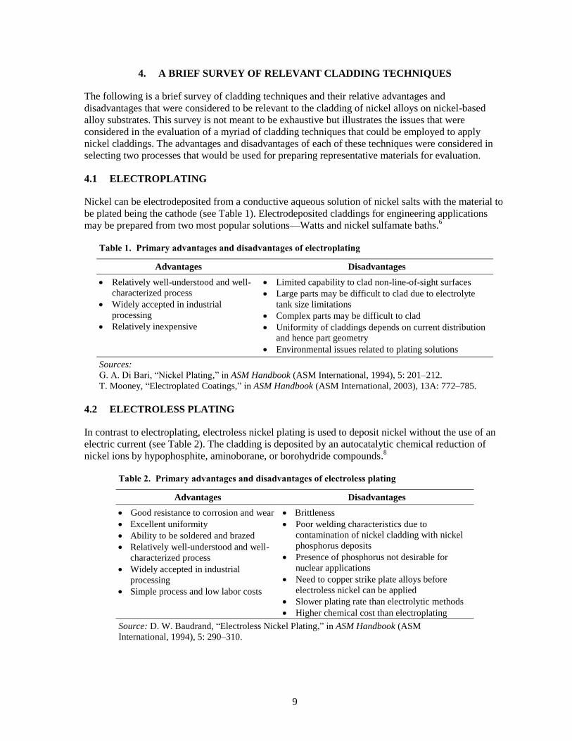
4.1 ELECTROPLATING
Nickel can be electrodeposited from a conductive aqueous solution of nickel salts with the material to
be plated being the cathode (see Table 1). Electrodeposited claddings for engineering applications
may be prepared from two most popular solutions—Watts and nickel sulfamate baths.6
Table 1. Primary advantages and disadvantages of electroplating
Advantages Disadvantages
Relatively well-understood and well-
characterized process
Widely accepted in industrial
processing
Relatively inexpensive
Limited capability to clad non-line-of-sight surfaces
Large parts may be difficult to clad due to electrolyte
tank size limitations
Complex parts may be difficult to clad
Uniformity of claddings depends on current distribution
and hence part geometry
Environmental issues related to plating solutions
Sources:
G. A. Di Bari, ―Nickel Plating,‖ in ASM Handbook (ASM International, 1994), 5: 201–212.
T. Mooney, ―Electroplated Coatings,‖ in ASM Handbook (ASM International, 2003), 13A: 772–785.
4.2 ELECTROLESS PLATING
In contrast to electroplating, electroless nickel plating is used to deposit nickel without the use of an
electric current (see Table 2). The cladding is deposited by an autocatalytic chemical reduction of
nickel ions by hypophosphite, aminoborane, or borohydride compounds.8
Table 2. Primary advantages and disadvantages of electroless plating
Advantages Disadvantages
Good resistance to corrosion and wear
Excellent uniformity
Ability to be soldered and brazed
Relatively well-understood and well-
characterized process
Widely accepted in industrial
processing
Simple process and low labor costs
Brittleness
Poor welding characteristics due to
contamination of nickel cladding with nickel
phosphorus deposits
Presence of phosphorus not desirable for
nuclear applications
Need to copper strike plate alloys before
electroless nickel can be applied
Slower plating rate than electrolytic methods
Higher chemical cost than electroplating
Source: D. W. Baudrand, ―Electroless Nickel Plating,‖ in ASM Handbook (ASM
International, 1994), 5: 290–310.

10
4.3 PHYSICAL VAPOR DEPOSITION—VACUUM EVAPORATION, SPUTTERING,
AND OTHER TECHNIQUES
Vapor-based processes that can be used for cladding include the physical vapor deposition (PVD)
techniques, such as vacuum evaporation, sputtering, ion plating, ion-beam assisted deposition, arc
deposition, and ion implantation. In the vacuum evaporation process, deposition is achieved from the
vapor phase containing the required atoms, typically provided by a vaporization source (see Table 3).
Deposition of high-purity films requires appropriate control of vacuum levels.9
Table 3. Primary advantages and disadvantages of vacuum evaporation
Advantages Disadvantages
High-purity films can be deposited over
large areas at a reasonable rate
Deposition can be carried out at low
substrate temperature and hence minimizes
issues with substrate microstructure and
property modification due to the cladding
process
Process can be scaled using large sources
Relatively inexpensive compared with
other PVD techniques
Film properties are poor and have the potential for
flaws (e.g., pinholes, porosity, residual stresses)
Lack of process control to improve film properties
High vacuum levels are required to obtain films of
good quality
A line-of-sight process and may not be suitable for
narrow diameter tubes
Substrate surface preparation may be critical in
determining adhesion and properties
Difficult to achieve uniformity of film thickness over
large areas
Higher capital costs when compared with other
techniques such as electroplating
Source: D. M. Mattox, ―Vacuum Deposition, Reactive Evaporation, and Gas Evaporation,‖ in ASM
Handbook (ASM International, 1994), 5: 556–572.
Sputtering is a nonthermal vaporization process in which surface atoms from a source are physically
ejected by transfer of momentum from an energetic bombarding species of atomic/molecular size.
Typically, sputtering uses a glow discharge or an ion beam to generate a flux of ions incident on the
target surface. The ions cause atoms and, in some cases, clusters of atoms to be knocked free from the
target surface by impact transfer, or sputtering. Redeposition of the sputtered atoms onto another
surface or substrate results in sputter deposition of cladding. Compared with other thin-film
deposition methods, sputter deposition techniques have several distinct advantages (see Table 4).9-11
Table 4. Primary advantages and disadvantages of sputtering
Advantages Disadvantages
Deposition can be carried out at low substrate
temperature and hence minimizes issues with
substrate microstructure and property
modification due to the cladding process
Uniformity of film thickness over large
areas
Good film adhesion
Well accepted industrially scalable,
environmentally friendly process
Slow deposition rates (typically less than 300 nm/min)
A line-of-sight process and may not be suitable for
narrow-diameter tubes or excessively large
components
Substrate surface preparation may be critical in
determining adhesion and properties
Setup costs are high because of vacuum and energy
efficiency is low (70% or more of the input energy is
expended in target heating).
Sources:
D. M. Mattox, ―Vacuum Deposition, Reactive Evaporation, and Gas Evaporation,‖ in ASM Handbook (ASM
International, 1994), 5: 556–572.
―CVD and PVD Coatings,‖ in ASM Handbook (ASM International, 2003), 13A: 759–762.
S. L. Rohde, ―Sputter Deposition,‖ in ASM Handbook (ASM International, 1994), 5: 573–581.
11
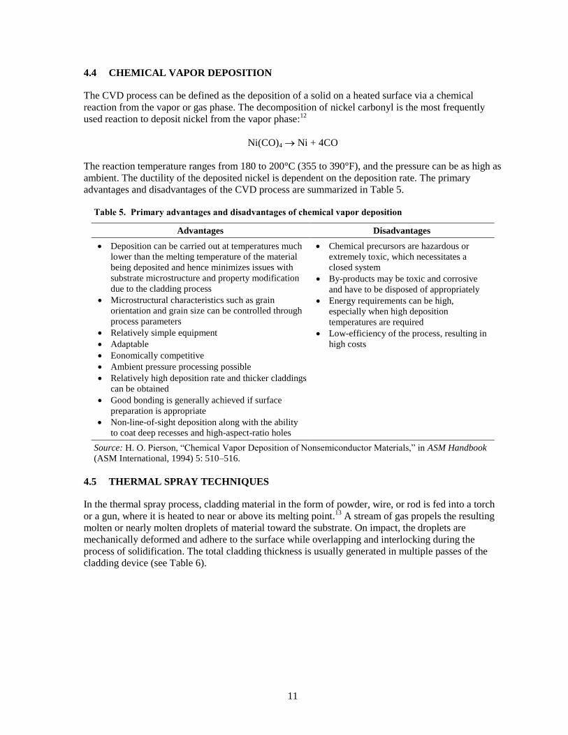
4.4 CHEMICAL VAPOR DEPOSITION
The CVD process can be defined as the deposition of a solid on a heated surface via a chemical
reaction from the vapor or gas phase. The decomposition of nickel carbonyl is the most frequently
used reaction to deposit nickel from the vapor phase:12
Ni(CO)4 Ni + 4CO
The reaction temperature ranges from 180 to 200°C (355 to 390°F), and the pressure can be as high as
ambient. The ductility of the deposited nickel is dependent on the deposition rate. The primary
advantages and disadvantages of the CVD process are summarized in Table 5.
Table 5. Primary advantages and disadvantages of chemical vapor deposition
Advantages Disadvantages
Deposition can be carried out at temperatures much
lower than the melting temperature of the material
being deposited and hence minimizes issues with
substrate microstructure and property modification
due to the cladding process
Microstructural characteristics such as grain
orientation and grain size can be controlled through
process parameters
Relatively simple equipment
Adaptable
Eonomically competitive
Ambient pressure processing possible
Relatively high deposition rate and thicker claddings
can be obtained
Good bonding is generally achieved if surface
preparation is appropriate
Non-line-of-sight deposition along with the ability
to coat deep recesses and high-aspect-ratio holes
Chemical precursors are hazardous or
extremely toxic, which necessitates a
closed system
By-products may be toxic and corrosive
and have to be disposed of appropriately
Energy requirements can be high,
especially when high deposition
temperatures are required
Low-efficiency of the process, resulting in
high costs
Source: H. O. Pierson, ―Chemical Vapor Deposition of Nonsemiconductor Materials,‖ in ASM Handbook
(ASM International, 1994) 5: 510–516.
4.5 THERMAL SPRAY TECHNIQUES
In the thermal spray process, cladding material in the form of powder, wire, or rod is fed into a torch
or a gun, where it is heated to near or above its melting point.13
A stream of gas propels the resulting
molten or nearly molten droplets of material toward the substrate. On impact, the droplets are
mechanically deformed and adhere to the surface while overlapping and interlocking during the
process of solidification. The total cladding thickness is usually generated in multiple passes of the
cladding device (see Table 6).

12
Table 6. Primary advantages and disadvantages of thermal spray technique
Advantages Disadvantages
Deposition can be carried out without
significant heating of the substrate hence
minimizes issues with substrate microstructure
and property modification due to the cladding
process
Ability to coat large areas at reasonable rates
Complex parts can be coated
A line-of-sight process and may not be suitable for
narrow-diameter tubes and deep cavities
Surface finish and composition of cladding have to
be monitored and controlled
Substrate surface preparation may be critical in
determining adhesion and properties.
Multiple passes may be required for relatively
thick claddings
Depending on the technique used, claddings may
have some porosity and may have low density
Source: R. C. Tucker, Jr, ―Thermal Spray Coatings,‖ in ASM Handbook (ASM International, 1994), 5: 497–
509.
4.6 WELD OVERLAY, LASER CLADDING, AND RELATED TECHNIQUES
In the weld-overlay/laser-cladding class of techniques, a source of heat is used to accomplish heating
and melting of the cladding material on top of the substrate to be cladded.14
The heat source can be a
welding torch, such as the torch used in the gas tungsten arc-welding process, or from a laser (see
Table 7). A certain amount of the substrate is also melted during the process, resulting in dilution of
the cladding layer (the amount of dilution depends on the amount of heat supplied).
Table 7. Primary advantages and disadvantages of weld overlay/laser cladding techniques
Advantages Disadvantages
Good adhesion with substrate due to intimate
mixing at the substrate-cladding interface
Limited capability to coat non-line-of-sight
surfaces
Ability to coat large areas at reasonable rates by
rastering
Thick claddings may be achievable in a single
pass
Surface preparation may be less critical since
high temperatures are involved
Typically a line-of-sight process and not suitable
for cladding narrow-diameter tubes or deep
cavities
Surface region is melted and resolidified,
resulting in microstructural and property
modifications of substrate region close to the
surface
Mixing between substrate surface and cladding
can result in modification of cladding
composition
Since high surface temperatures are involved, a
heat-affected zone exists underneath the surface
layer, resulting in microstructure and property
modifications of the substrate
Process parameters are critical in determining
properties because they determine heating and
cooling and hence cladding and near-surface
substrate properties
Source: K. P. Cooper, ―Laser Surface Processing,‖ in ASM Handbook (ASM International, 1992),
18: 861–872.

13
4.7 COEXTRUSION
Coextrusion is the process of simultaneous extrusion of materials to form a bimetallic composite (see
Table 8). In the coextrusion process, a core material is extruded along with the clad material through a
convergent die. The concurrent deformation of the core and the clad material results in the formation
of an interfacial bonding layer between the core and the cladding. The coextrusion or codrawing
process can be carried out at appropriate temperatures for the system of materials under consideration
and can be accomplished using conventional extrusion or drawing equipment. Other variations, such
as friction extrusion or hydrostatic extrusion, are also possible. The coextrusion process is typically
carried out using materials with widely different mechanical properties—either hard core/soft clad or
soft core/hard clad. Hence, successful coextrusion depends on a number of factors, such as
metallurgical and mechanical compatibility of the two materials and a number of process parameters
that influence the flow behavior of the two materials.15
Table 8. Primary advantages and disadvantages of the coextrusion process
Advantages Disadvantages
Equipment is relatively simple; conventional
metal-working equipment may be adequate
Long lengths of materials can be processed
fairly efficiently; high throughput can be
achieved
Cladding of internal surfaces possible using
nickel as the internal clad layer followed by
piercing to form hollow tube
Generalized process recipe not available; significant
investment in process development is needed
Customized process requires new process
development if material combinations/properties are
changed
Surface cleanliness may be critical for good
adhesion
May be more suitable for fabrication of tubes than
for other bulk components
Can be primarily used for initial fabrication of
components but not for field fabrication or for repair
Source: R. Srinivasan and C. S. Hartley, ―Coextrusion,‖ in ASM Handbook (ASM International, 2005), 14A:
505–515.


15
5. PROCESSING AND EVALUATION OF NICKEL CLADDINGS
5.1 SELECTION AND PROCESSING OF NICKEL CLADDINGS
After a careful examination of the capabilities, advantages, and disadvantages of the various
technologies along with the needs for FHR components, two cladding technologies were selected for
initial cladding trials. These are (1) a laser-based surface cladding technique that is primarily
applicable to coat surfaces with line-of-sight access and (2) CVD using the nickel-carbonyl process
that is applicable to the cladding of surfaces with no line-of-sight access, such as long, narrow tubes
used in heat exchangers. Very few techniques have the capability to coat surfaces with no line-of-
sight access, and hence the nickel-carbonyl process was a preferred technique for cladding such
surfaces. A number of techniques could satisfy the required criteria for cladding surfaces with line-of-
sight access; in this case, preference was given to techniques for which the technology is readily
available at Oak Ridge National Laboratory. The following is a brief description of the two
processing techniques used in this work.
Laser-based surface cladding: In the laser-based cladding technique, the surface to be clad is
initially spray-coated with a high-purity nickel powder mixed with a polymer-based binder. In
this case, spherical nickel powder -325 mesh 99.9% (AEE part# NI-120) was used for the coatings.
Following an initial bake of the precursor, a high powered Nd-YAG laser is used to rapidly heat
the surface layer to a temperature sufficient to melt it. The laser used for this project was a
Trumpf HL4006D with a 4kW 1064nm continuous Nd:YAG beam connected to a fabricated
brass water-cooled lens assembly. The laser beam diverges from the 600μm fiber into the
focusing optics at an angle of 25mRad. The beam is then passed through a series of 3 lenses
housed in a custom water cooled brass fixture. The divergent beam is translated into a parallel
round beam by a plano-convex lens at a predetermined distance from the tip of the fiber. The
beam is now focused in the direction perpendicular to its travel direction by a plano-concave lens,
and is focused again in the direction parallel to its travel direction by another plano-concave lens
placed in relation to the previous lens. The beam then travels through a clear protective slide, and
makes contact with the sample. When focused, the approximate dimensions of the beam are
1mm x 10mm. The laser beam scans continuous offset tracks across the sample’s surface
horizontally, until the full surface is processed. Depending on the amount of heat supplied, a
small portion of the substrate is also melted at the same time, which allows intimate mixing
between the precursor layer and the substrate layer. Due to the relatively small size of the laser
beam, the beam is rastered on the surface of the specimen in order to cover areas larger than the
beam diameter. Figure 2 shows a picture of the laser processing setup.
Table 2 shows a summary of the parameters used for processing the coatings. Primary processing
that was changed during the trials was the laser power used for processing of the coatings. The
linear travel speed of the laser was held constant and both alloy 617 substrates and alloy 800H
substrates were used for processing.

16
Fig 2. Image of the setup used for laser processing of coatings.
Table 9. Effects of some commonly present elements.
Power (watts)
Coating Thickness
(μm)
Substrate Alloy
Substrate Thickness (in) Cover Gas
2500 100 617 0.2” Argon
3000 100 617 0.2” Argon
3500 100 617 0.2” Argon
4000 100 617 0.2” Argon
2500 100 800H 0.5” Argon
3000 100 800H 0.5” Argon
3500 100 800H 0.5” Argon
4000 100 800H 0.5” Argon
Table 10. Nominal Compositions of alloy substrates used in the study.
Alloy Ni Fe Cr Mn Co Cu Mo Si Ti Al
617 54.9 1 21.4 0 12.8 0 8.5 0.1 0.1 1.2
800H 31.1 45.3 21.6 0.7 0.3 0.5 0 0.3 0 0.2
Figure 4(a) shows a small block coated on the top surface using a laser-based technique.
Chemical Vapor Deposition of Nickel: In order to assess the deposition quality and adhesion
properties of nickel chemical vapor deposition (CVD) onto high-strength nickel alloys, samples of

17
Nickel Powder
Nickel Carbonyl Reactor
Ca
rbo
n
Mo
no
xid
e
Deposition Chamber
Heater
Samples
Ni(CO)4
CO
Incin
era
tor
Arg
on
Hyd
rog
en
ArH2
CO+Ni(CO)4
each Alloy 800H and Inconel™ 617 were CVD coated using a commercial vendor. Chemical Vapor
Metal Refining Inc. was the vendor selected to perform the nickel CVD coatings.
The nickel deposition process selected is a metal organic chemical vapor deposition (MOCVD)
process that is based on the nickel carbonyl process developed in 1889 by Ludwig Mond and his
coworker Carl Langer and Friedrich Quincke16
. In this process four molecules of carbon monoxide at
temperatures between 40 and 100°C are reacted with active nickel to form a colorless gas, nickel
tetracarbonyl, as shown in equation 1. Nickel that has the oxide surface that forms due to air
exposure does not react with carbon monoxide at these temperatures.
Nickel tetracarbonyl decomposes back into nickel and carbon monoxide at temperatures between 150
and 300 °C. Depending on temperature of decomposition, nickel tetracarbonyl decomposes onto a
surface or into the gas phase. Generally, at temperatures below 200 °C nickel deposits onto surfaces
and at temperatures above 220 °C nickel powder is produced.
The nickel carbonyl formation and decomposition reactions are exploited to form conformal nickel
layers on substrates by first forming the nickel tetracarbonyl gas and then decomposing the gas on a
heated substrate in a reaction chamber. The process is illustrated in Error! Reference source not
found.. The nickel deposition rate depends primarily on the delivery rate of the precursor nickel
tetracarbonyl gas to the surface, as the decomposition reaction is rapid relative to the gas motion.
Deposition is done at elevated pressure, and deposition rates typically vary from 250 µm to 750 µm
per hour. Typical carbon contamination within the deposited nickel is about 60 ppm.
Fig 3. Nickel tetracarbonyl deposition process
As a vapor phase conformal coating process the MOCVD can be applied to complex shapes. The
only shape restriction for the process is due to the combination of gas flow dynamics and the reaction
rate of the nickel tetracarbonyl gas with the substrate. Essentially the gas composition, flow rate, and
reaction temperature must be optimized to ensure that uniform composition gas reaches all portions of
deep shapes such as capillary tubing or only the inlet portions of the tube will be coated.

18
Sample Coating
Five samples (~25 x 6 x 6 mm) of each Inconel™ 617 and Alloy 800H were coated with nickel. In
order to remove any surface contamination, the alloys were first placed into a deposition chamber
with inlet and outlet fixturing for the necessary gasses. The chamber was then purged with argon and
then hydrogen. While filled with hydrogen, the chamber was heated to 375 °C and held for 40 - 60
minutes to remove any surface organic contamination. Note: this process will not remove the thin,
native chromium oxide protective, tarnish layer on the surface of the alloys. As a diffusion barrier
may be useful for thin section base metal parts and in-situ flash pickling requires the use of strong
acids, it was elected to leave the thin tarnish layer in place. The deposition chamber was made from a
copper tube with a ceramic heater element.
The Inconel™ 617 specimens were processed for 8 hours at 200 °C at a pressure of 300 kPa and
the Alloy 800H specimens were processed for 2 hours at 200 °C at a pressure of 500 kPa. After
the depositions were complete the system was purged with argon and allowed to cool down.
(a)
(b)
Fig 4. (a) Optical image of a nickel-based alloy substrate with a nickel cladding applied using a laser-
based surface cladding technique. (b) Optical image of three nickel-based substrates coated using the
CVD nickel-carbonyl process.
5.2 OBJECTIVES OF CLADDING EVALUATIONS
Claddings applied by means of the selected processes were subject to a preliminary evaluation
focused on the following criteria:
presence of pinholes, voids, surface cracks, and significant internal cracks;
uniformity in thickness;
microstructure of cladding and the near-surface substrate region;
presence or absence of debonding at the interface between the cladding and the substrate; and
hardness of the cladding and comparison with that of the substrate.

19
composition of cladding and mixing between substrate and cladding;
The results of the evaluation are provided in sections 5.3
5.3. RESULTS OF EVALUATION
5.3.1 Laser Claddings
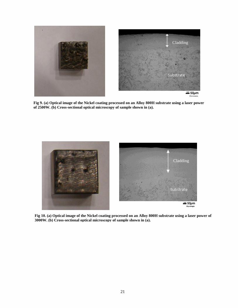
Figures 4 (a), 5 (a), 6 (a), and 7(a) show optical images of the alloy 617 substrates coated with Nickel
cladding at laser powers of 2500W, 3000W, 3500W, and 4000W respectively while figures 4 (b), 5
(b), 6 (b), and 7(b) show optical images of cross-sections following the cladding process. Figures 8
(a), 9 (a), 10 (a), and 11(a) show optical images of the alloy 800H substrates coated with Nickel
cladding at laser powers of 2500W, 3000W, 3500W, and 4000W respectively while figures 8 (b), 9
(b), 10 (b), and 11(b) show optical images of cross-sections following the cladding process. In all
cases, the clad surface in figure (b) is on top.
Cladding
Substrate
Fig 5. (a) Optical image of the Nickel coating processed on an Alloy 617 substrate using
a laser power of 2500W. (b) Cross-sectional optical microscopy of sample shown in (a).
Cladding
Fig 6. . (a) Optical image of the Nickel coating processed on an Alloy 617 substrate using a
laser power of 3000W. (b) Cross-sectional opetical microscopy of sample shown in (a).

20
Cladding
Cladding
Fig 7. (a) Optical image of the Nickel coating processed on an Alloy 617 substrate using a laser power
of 3500W. (b) Cross-sectional optical microscopy of sample shown in (a).
Fig 8. (a) Optical image of the Nickel coating processed on an Alloy 617 substrate using a laser power of
4000W. (b) Cross-sectional optical microscopy of sample shown in (a).
21
Cladding
Cladding
Fig 10. (a) Optical image of the Nickel coating processed on an Alloy 800H substrate using a laser power of
3000W. (b) Cross-sectional optical microscopy of sample shown in (a).
Fig 9. (a) Optical image of the Nickel coating processed on an Alloy 800H substrate using a laser power
of 2500W. (b) Cross-sectional optical microscopy of sample shown in (a).

22
The following issues are noted from these micrographs:
In general, the quality of coatings was acceptable with identified presence of few voids, pinholes,
and cracks. There were regions in which the coatings had spalled; it is anticipated that
optimization of the process would minimize these spalled regions.
Good adhesion along with good mixing was present at the interface between the cladding and the
substrate;
Cladding
Cladding
Fig 11. (a) Optical image of the Nickel coating processed on an Alloy 800H substrate using a laser power of
3500W. (b) Cross-sectional optical microscopy of sample shown in (a).
Fig 12. (a) Optical image of the Nickel coating processed on an Alloy 800H substrate using a laser power
of 4000W. (b) Cross-sectional optical microscopy of sample shown in (a).

23
A portion of the substrate from the near-surface region was observed to have melted and
intermixed with the cladding material. As expected, the size of this region increased with
increasing laser power indicated by the larger
An important question that needs to be answered is the extent of mixing between the Nickel cladding
and the substrate and hence the composition of the clad layer in the near-surface region.
Compositions of the near surface region and at the substrate near the interface were measured using
Wavelength Dispersive Spectroscopy (WDS). Figure
0
10
20
30
40
50
60
70
0 200 400 600 800
Microns
Wt.
%
Co
Mo
Cr
Ni
0
10
20
30
40
50
60
70
80
0 200 400 600 800 1000 1200
Microns
WT
.%
Co
Mo
Cr
Ni
Cladding
Cladding
Fig 13. (a) Cross-sectional optical microscopy of Nickel coating processed on an Alloy 617 substrate
using a laser power of 2500W. (b) Measured composition profile along the line shown in (a). The
composition of the top surface is shown on the right.
Fig 14. (a) Cross-sectional optical microscopy of Nickel coating processed on an Alloy 617 substrate
using a laser power of 4000W. (b) Measured composition profile along the line shown in (a). The
composition of the top surface is shown on the right.
Surface
Surface

24
0
10
20
30
40
50
60
70
80
90
100
0 200 400 600 800 1000
Micron
Wt.
%
Fe
Ni
Cr
0
10
20
30
40
50
60
70
80
0 200 400 600 800 1000 1200
Micron
Wt.
%
Fe
Ni
Cr
Cladding
Cladding
Fig 16. (a) Cross-sectional optical microscopy of Nickel coating processed on an Alloy 800H substrate using
a laser power of 4000W. (b) Measured composition profile along the line shown in (a). The composition of
the top surface is shown on the right.
Fig 15. (a) Cross-sectional optical microscopy of Nickel coating processed on an Alloy 800H substrate using
a laser power of 2500W. (b) Measured composition profile along the line shown in (a). The composition of
the top surface is shown on the right.
Surface
Surface
25
6. WELDING OF NICKEL-CLAD NICKEL-BASED ALLOYS
A cursory literature review indicates there is very little published information about welding or weld
performance issues related to welding of nickel-coated nickel-based alloys. Based on a general
understanding of welding, one can imagine there are two types of concerns for this situation. The first
is the effect of incorporating any nickel cladding into a weld deposit made in a nickel-based alloy or
into base metal heat-affected zones. The second type of concern is whether nickel cladding integrity
can be maintained after welding operations.
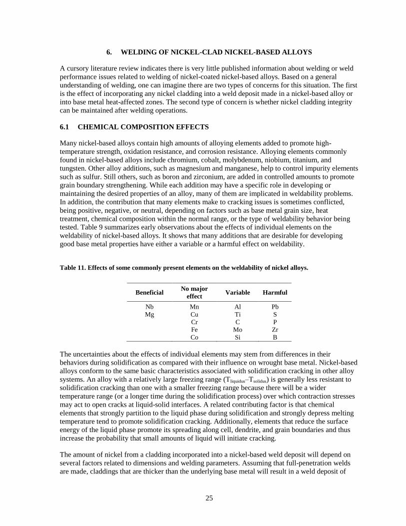
6.1 CHEMICAL COMPOSITION EFFECTS
Many nickel-based alloys contain high amounts of alloying elements added to promote high-
temperature strength, oxidation resistance, and corrosion resistance. Alloying elements commonly
found in nickel-based alloys include chromium, cobalt, molybdenum, niobium, titanium, and
tungsten. Other alloy additions, such as magnesium and manganese, help to control impurity elements
such as sulfur. Still others, such as boron and zirconium, are added in controlled amounts to promote
grain boundary strengthening. While each addition may have a specific role in developing or
maintaining the desired properties of an alloy, many of them are implicated in weldability problems.
In addition, the contribution that many elements make to cracking issues is sometimes conflicted,
being positive, negative, or neutral, depending on factors such as base metal grain size, heat
treatment, chemical composition within the normal range, or the type of weldability behavior being
tested. Table 9 summarizes early observations about the effects of individual elements on the
weldability of nickel-based alloys. It shows that many additions that are desirable for developing
good base metal properties have either a variable or a harmful effect on weldability.
Table 11. Effects of some commonly present elements on the weldability of nickel alloys.
Beneficial No major
effect Variable Harmful
Nb
Mg
Mn
Cu
Cr
Fe
Co
Al
Ti
C
Mo
Si
Pb
S
P
Zr
B
The uncertainties about the effects of individual elements may stem from differences in their
behaviors during solidification as compared with their influence on wrought base metal. Nickel-based
alloys conform to the same basic characteristics associated with solidification cracking in other alloy
systems. An alloy with a relatively large freezing range (Tliquidus–Tsolidus) is generally less resistant to
solidification cracking than one with a smaller freezing range because there will be a wider
temperature range (or a longer time during the solidification process) over which contraction stresses
may act to open cracks at liquid-solid interfaces. A related contributing factor is that chemical
elements that strongly partition to the liquid phase during solidification and strongly depress melting
temperature tend to promote solidification cracking. Additionally, elements that reduce the surface
energy of the liquid phase promote its spreading along cell, dendrite, and grain boundaries and thus
increase the probability that small amounts of liquid will initiate cracking.
The amount of nickel from a cladding incorporated into a nickel-based weld deposit will depend on
several factors related to dimensions and welding parameters. Assuming that full-penetration welds
are made, claddings that are thicker than the underlying base metal will result in a weld deposit of

26
high nickel concentration relative to that of the base metal. Adding nickel to a nickel-based alloy will
tend to increase its melting temperature and decrease its freezing range. Because of this, the added
nickel would not be expected to increase the tendency of the base metal to crack during solidification.
Concerns about the added nickel will diminish proportionately as the thickness of the cladding
becomes a smaller fraction of the combined thickness of the cladding and the base metal.
Solid-state diffusion could also modify the compositions of both claddings and base metals in base-
metal heat-affected zones. Generally, heat-affected zones will experience temperatures high enough
to permit significant solid-state diffusion for only very short times. From this, it seems reasonable to
expect that local properties in heat-affected zones will not be significantly modified by welding
operations.
6.2 CLADDING INTEGRITY EFFECTS
Maintaining cladding integrity after any welding operations is an important concern. Clearly,
anywhere the base metal is melted, the nickel cladding will be incorporated into the resulting weld
deposit. A high-nickel external surface would require either recladding or making the exposed weld
beads of high-nickel alloy. Welding electrodes that approach chemical composition of 99% Ni are
commercially available.
The integrity of claddings in heat-affected zones will depend on such factors as cladding composition,
thickness, and original adherence as well as welding parameters and the welding process. The thermal
expansion behavior of nickel claddings should be similar to that of nickel-based alloys and should
minimize or eliminate buckling failures due to local heating. Because nickel-based alloys typically
have lower melting temperatures than pure nickel, concerns about local loss of integrity due to
preferential melting should be minimized.
6.3 REMARKS
Clearly, this assessment is not exhaustive. Issues related to both chemistry modifications and cladding
integrity will depend on numerous factors, including but not limited to the following:
actual chemical compositions of claddings and base metals,
the relative thicknesses of claddings and base metals,
intrinsic adhesion of the cladding to the base metal,
intrinsic strength and ductility of the nickel cladding,
the welding process,
whether or not filler metal is used for welding,
welding parameters, and
sensitivity of the exposed nickel to low concentrations of alloying elements.

27
7. REFERENCES
1. D. F. Williams, L. M. Toth, and K. T. Clarno, Assessment of Candidate Molten Salt Coolants for
the Advanced High Temperature Reactor (AHTR), ORNL/TM-2006/12, Oak Ridge National
Laboratory, Oak Ridge, Tenn., March 2006.
2. D. E. Holcomb, S. M. Cetiner, G. F. Flanagan, F. J. Peretz, and G. L. Yoder, Jr., An Analysis of
Testing Requirements for Fluoride Salt-Cooled High Temperature Reactor Components,
ORNL/TM-2009/297, Oak Ridge National Laboratory, Oak Ridge, Tenn., November 2009.
3. D. E. Holcomb and S. M. Cetiner, An Overview of Liquid-Fluoride-Salt Heat Transport Systems,
ORNL/TM-2010/156, Oak Ridge National Laboratory, Oak Ridge, Tenn., September 2010.
4. L. J. Koch, H. O. Monson, W. R. Simmons, M. Levenson, F. Verber, E. Hutter, R. A. Jaross,
T. R. Spalding, J. R. Simanton, and A. Lovoff, ―Construction Design of EBR-II: An Integrated
Unmoderated Nuclear Power Plant,‖ Proc. Second United Nations International Conference on
the Peaceful Uses of Atomic Energy,‖ Geneva, Switzerland, June 1958.
5. D. F. Wilson, Effects of Materials Testing Requirements and Planning for Implementation of
Initial Test Program for Liquid Salt Intermediate Loops, ORNL/GEN4/LTR-6-029, Oak Ridge
National Laboratory, Oak Ridge, Tenn., September 2006.
6. G. A. Di Bari, ―Nickel Plating,‖ in ASM Handbook (ASM International, 1994), 5: 201–212.
7. T. Mooney, ―Electroplated Coatings,‖ in ASM Handbook (ASM International, 2003),
13A: 772–785.
8. D. W. Baudrand, ―Electroless Nickel Plating,‖ in ASM Handbook (ASM International, 1994),
5: 290–310.
9. D. M. Mattox, ―Vacuum Deposition, Reactive Evaporation, and Gas Evaporation,‖ in ASM
Handbook (ASM International, 1994), 5: 556–572.
10. ―CVD and PVD Coatings,‖ in ASM Handbook (ASM International, 2003), 13A: 759–762.
11. S. L. Rohde, ―Sputter Deposition,‖ in ASM Handbook (ASM International, 1994), 5: 573–581.
12. H. O. Pierson, ―Chemical Vapor Deposition of Nonsemiconductor Materials,‖ in ASM
Handbook (ASM International, 1994) 5: 510–516.
13. R. C. Tucker, Jr, ―Thermal Spray Coatings,‖ in ASM Handbook (ASM International, 1994),
5: 497–509.
14. K. P. Cooper, ―Laser Surface Processing,‖ in ASM Handbook (ASM International, 1992),
18: 861–872.
15. R. Srinivasan and C. S. Hartley, ―Coextrusion,‖ in ASM Handbook (ASM International, 2005),
14A: 505–515.
