civil engineering department - ingeciber · your engineering partner ingeciber, s ... technical...
TRANSCRIPT

1
Your Engineering Partner
Ingeciber, S.A. Av. Monforte de Lemos, 189. 28035 – Madrid. Spain Phone: +34 91 386 2222 C.I.F.:A-78348950 www.ingeciber.com [email protected]
Your engineering partner
Finite Elements Models for Reactor Buildings and Reactor Primary Loop and Computational Analyses.
Civil Engineering Department
Consultancy jobs descriptions and case studies
April 2017 Ed.

2
Your Engineering Partner
INDEX
1. INTRODUCTION TO INGECIBER ...................................................................................... 4
2. INTRODUCTION TO THE ENGINEERING DEPARTMENTS .......................................... 5
2.1 CONSULTANCY ........................................................................................................................................ 5
2.2 EDUCATION ............................................................................................................................................. 5
3. ADDITIONAL INFORMATION ........................................................................................... 6
4. CONSULTANCY JOBS DESCRIPTION & PROJECT´S REFERENCE ............................. 7
4.1 SEISMIC RECALCULATION OF NPP MOCHOVCE ...................................................................................... 8
4.2 DAM OF CORROSPARRI (ÁLAVA) ............................................................................................................. 9
4.3 DAM DO BAIXO SABOR (PORTUGAL) .................................................................................................... 10
4.4 REACTOR RENEWAL INSIDE AN OLD PRESTRESSED ONE ...................................................................... 11
4.5 FOUNDATION REPAIR CHECKING OF WIND TURBINES ......................................................................... 12
4.6 ANALYSIS AND DESIGN OF A TURBINE FOUNDATION .......................................................................... 13
4.7 BIOMA SOUTH OF BOTANICAL GARDEN OF OMAN .............................................................................. 14
4.8 VIBRATIONAL ANALYSIS CRYOPLANT BUILDING ITER. FUSION FOR ENERGY ....................................... 15
4.9 SCREEN WALL AND GALLERY ANALYSIS IN SÃO PAULO UNDERGROUND............................................. 16
4.10 FEM ANALYSIS OF A TUNNE BELOW BARAJAS AIRPORT (MADRID) ...................................................... 17
4.11 REINFORCED CONCRETE SILO 100M HIGH (BILBAO) ............................................................................ 18
4.12 ILL HEADQUARTERS SEISMIC RESTORATION PROJECT ......................................................................... 19
4.13 FE MODEL OF A TRANSITION BALLASTLESS - BALLASTED TRACK ......................................................... 20
4.14 POWER PLANT MODEL. CHECK AND DESIGN ACCORDING TO CODES .................................................. 21
4.15 SEISMIC ANALYSIS OF A CABLE TRAY SUPPORT .................................................................................... 22
4.16 INNOVATIVE NUMERICAL METHODOLOGIES FOR STRUCTURAL OPTIMIZATION ................................. 23

3
Your Engineering Partner
4.17 FIRE SIMULATION IN M-30 TUNNELS (MADRID) ................................................................................... 25
4.18 CFD VIBRATION ANALYSIS OF A HOWELL-BUNGER VALVE INSTALLED AT A DAM ............................... 26
4.19 FLOW AND AERATION STUDY IN A WWTP REACTOR ........................................................................... 28
4.20 WIND ACTION IN A WIND TURBINE FIELD ............................................................................................ 29
4.21 WIND ACTION ON A SOLAR PLANT ....................................................................................................... 30
4.22 ANALYSIS OF WIND EFFECT ON AN HELIOSTAT .................................................................................... 31
4.23 CFD STUDY OF CHANNELING INFRASTRUCTURE .................................................................................. 32
4.24 ADVANCE OF SEDIMENT PARTICLES DURING WASHING PROCESS IN A STORM TANK ........................ 33
4.25 CFD STUDY OF A STORAGE AND PUMPING POOL ................................................................................ 34
4.26 ANALYSIS OF THE EVOLUTION OF AN EXPLOSION'S EXPANSIVE WAVE ............................................... 35
4.27 SIMULATION OF TWO FIXED EFFLUENT AND ANALYSIS OF THE DILUTION OF ITS SALT CONTENT ...... 36
4.28 WAVE INFILTRATION STUDY THROUGH A SEA DIKE ............................................................................. 37
4.29 FLOOD FLOW IN EL HIERRO RAVINE ..................................................................................................... 38
4.30 DESIGN OF A DEFLECTOR WALL IN A PUMPS HOUSE TO OPTIMIZE THE FLUX ..................................... 39

4
Your Engineering Partner
1. INTRODUCTION TO INGECIBER
INGECIBER S.A. is a pioneering company in the field of calculations using mathematical
models, also known as Computer Aided Engineering (CAE). Established in 1986, Ingeciber’s
main business was the use, distribution, technical support and training of users of the FEM
software ANSYS for 25 years. For the last five years, Ingeciber has performed the same
activities with the FEM software PATRAN/ MSC NASTRAN and now Ingeciber distributes a
Structural FEM software called CivilFEM.
CivilFEM, FEM software developed by Ingeciber, emerged by using ANSYS’s own
programming for the civil calculations performed in the company a globally unique
customization of ANSYS for Civil Engineering analyses. Since 2010, Ingeciber has also been
developing a new version of the software called CivilFEM Powered by Marc, the first version
of which came out on 2015.
Ingeciber business lines
INGECIBER S.A, after 30 years of offering CAE services, has a team of more than 30 highly-
qualified professionals, of whom 85% of them are engineers, and more than 1,000
CONSULTANCY
MECHANICALEngineering
CFD
CIVILEngineering
CAE Software DISTRIBUTION
MECHANICAL CAE software
CFD software
CIVIL CAE software
EDUCATION
Int'l UNED-Ingeciber
FEA MASTER'S
ICAEEC
FEA e-learning platform
CAE onsitetraining
Software DEVELOPMENT
CivilFEMpowered by MARC
CivilFEMfor ANSYS
R&D PROJECTS

5
Your Engineering Partner
companies have hired our services so far. A charter member of Technet-Alliance – an
association made up of more than 50 CAE companies located in 22 countries, with more
than 2,500 CAE engineers-, Ingeciber offers continuous development of new CAE
technologies and their practical application in the calculations and projects we perform.
2. INTRODUCTION TO THE ENGINEERING DEPARTMENTS
2.1 CONSULTANCY
Ingeciber has two engineering departments, the Mechanical and CFD Engineering
department and the Civil Engineering department. The engineering departments have dealt
with different projects using FEM and CFD software, such as structural analyses, heat
transfer, fluid analysis using CFD software, electromagnetism, rigid/flexible solid mechanics
– mechanical systems, etc. Some examples of the work performed by the Civil Engineering
department are shown in following sections of this paper.
The FEM and CFD software available for the engineering departments to use to perform
these analyses are: ANSYS, CivilFEM for ANSYS, CivilFEM powered by Marc, CFD++, XFlow
and modeFRONTIER.
2.2 EDUCATION
International online FEA Master's program of UNED
For over twenty-two years, Ingeciber has collaborated with UNED University on the
International Master’s in Theoretical and Practical Application of the Finite Element Method
and CAE Simulation, and more than 3,600 students have graduated.
The Mechanical and Civil Engineering Departments of Ingeciber are in charge of the
Specialized Module’s application and practical subjects of Dynamic Analysis, Nonlinear
Analysis, Heat Transfer Analysis, Advanced Steel Structures Analysis, Composites, Fluid
Mechanics, Advanced Concrete Structures Analysis and Geotechnics.

6
Your Engineering Partner
The global interest received for this Master´s Program motivated us to expand it into
English. By partnering with local companies who help support and promote this program
within their specific regions, we have made participating and studying this program possible
from anywhere in the world. This demonstrates that UNED´s Master’s FEA program has
obtained worldwide acceptance and prestige.
Complete information about the Master’s is available at www.uned.es/mastermef
International online CAE Education CENTER – ICAEEC
The goal of this online Education CENTER created by Ingeciber is to develop a new series
of online CAE Power courses based on industry standard tools using real world examples
that provide students with real experience that they can use in the workplace.
Unlike OEM based training courses, which are built around theoretical exercises, ICAEEC
Power CAE courses are designed to give students the practical knowledge and skills needed
to perform complex engineering analysis at their job.
Complete information about ICAEEC is available at www.icaeec.com
3. ADDITIONAL INFORMATION
More information about the different business lines of Ingeciber is available at the websites
shown below:
Ingeciber website: www.ingeciber.com
CivilFEM website: www.civilfem.com
Int’l UNED-Ingeciber FEA Master’s: www.uned.es/mastermef
Int’l online CAE Education CENTER: www.icaeec.com
Ingeciber Linkedin: https://www.linkedin.com/company/ingeciber
Ingeciber Twitter: @Ingeciber. https://twitter.com/Ingeciber

7
Your Engineering Partner
4. CONSULTANCY JOBS DESCRIPTION & PROJECT´S REFERENCE
•Statics and Dinamics.
•Linear and Non Linear.
•Construction processes and evolutive processes in general.
•Seismic analysis.
•Rheological phenomena.
•Testing and design following codes & standards of concrete and steel structures.
•Pre- and post-tensioned concrete.
Structural Calculations
•Structural calculation.
•Construction process.
•Seismic analysis.
•Active reinforcements.
Bridges,OffShore and Oil&Gas
•Structural calculations, linear and non-linear.
•Thermal studies for construction and operation.
•Seismic analysis.
•Construction processes (structural and thermal).
•Seismotectonic studies and induced seismicity.
•3D hydraulic analysis 3D of spillways, drains...
Concrete and loose
material Dam
•Deep foundations, piles and micropiles.
•Retaining walls (11/2D, 2D y 3D).
•Slope stability.
•Seepage analysis.
•Reinforced earth.
Terrain
•External aerodynamic CFD analyses: aircrafts, wind turbines, buildings, etc
•Internal aerodynamic CFD analyses: equipment refrigeration, HVAC, gas distribution in installations, etc
•Hydrodynamic CFD analyses: ducts, water canals, pipelines, pumps installations, valves, mixing installations, waste-water treatment plants, etc
•Other CFD analyses: multiphase simulations, moving geometries, FSI simulations, combustion, reactions, supersonic, transonic, etc
CFD analysis
• 2D and 3D tunnels, mines and hells.
• Construction process.
• Seismic analysis.
• Lining, anchorages...
• Initial terrain stress.
Tunnels

8
Your Engineering Partner
4.1 SEISMIC RECALCULATION OF NPP MOCHOVCE
Goal
Seismic recalculation of NPP Mochovce
Calculations Steps
Generation of the geometric model of the whole nuclear auxiliary building
Generation of the overall structural FE model;
Thermal analysis on the FE model of the building
Static analysis on the FE model of the building, to assess the stress field on the structures
and the generalized forces (moments, forces) on all the members, shells and beams, as well
as the displacement field on the structures
Response spectrum analysis on the FE model of the building, to assess the stress field on
the structures and the generalized forces ( moments, forces) on all the members, shells and
beams, as well as the displacement field on the structures
Time history analyses on the FE model of the buildings, using 7 terns of accelerograms as
input, to compute the resultant accelerograms in numerous selected locations on the
structure floors as well as the displacement field of the structure as envelope of the
maximum values
Assessment of the structural resistance against the complete load combination and
computation of the HCLPF for each and every structural member and for the whole
building. Calculation of the HCLPF value with CivilFEM
9
Your Engineering Partner
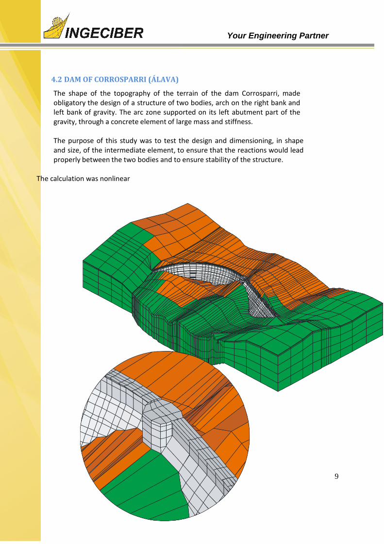
4.2 DAM OF CORROSPARRI (ÁLAVA)
The shape of the topography of the terrain of the dam Corrosparri, made obligatory the design of a structure of two bodies, arch on the right bank and left bank of gravity. The arc zone supported on its left abutment part of the gravity, through a concrete element of large mass and stiffness.
The purpose of this study was to test the design and dimensioning, in shape and size, of the intermediate element, to ensure that the reactions would lead properly between the two bodies and to ensure stability of the structure.
The calculation was nonlinear

10
Your Engineering Partner
4.3 DAM DO BAIXO SABOR (PORTUGAL)
The dam do Baixo Sabor is an arch dam, placed on the north of Portugal. Is a tall structure in which is necessary analyze the concrete temperature evolution during the construction in different cooling and environmental hypothesis (cool water, river water or both).
The cooling system consists of the
arrangement of coils. The purpose of this
study was to dimension the cooling system.
A thermal transitory and evolution calculation was performed taking as reference the values of the permissible thermal indicators proposed in the Technic Guide nº 2 of the Spanish Committee of large dams..
Thermal gradient in one of the phases of construction

11
Your Engineering Partner
4.4 REACTOR RENEWAL INSIDE AN OLD PRESTRESSED ONE
Object
• Reactor renewal inside a old prestressed one
RC Containment Building
Nonlinear Calculations Steps
• Step 1
• The whole model subjected to self weight and an
internal 35 t/m2 pressure
• Step 2
• A hole is drilled through the cylinder • All cables attached to this hole disappear • The internal pressure disappears as well
• Step 3
• The hole is refilled using concrete
• All the cables previously switched off
are switched on again
• Internal pressure is applied again

12
Your Engineering Partner
4.5 FOUNDATION REPAIR CHECKING OF WIND TURBINES
Foundation repair checking of wind turbines in Pedregoso wind park.
The study is focused in the foundation critic zones checking. These areas are more
susceptible to damage. This study put the focus on the part of the original foundation
where the active bars are anchored guarantying the union between the design repair
and the existing foundation.
There results are compared with the repair-less foundations, with the goal of
determining their ultimate load and the necessity of being repaired or improved.
An static and nonlinear FE model of the existent foundation has been modeled
corresponding to a standard wind turbine. This model takes into account the repair
proposed by the customer with the different load cases acting on the structure.

13
Your Engineering Partner
4.6 ANALYSIS AND DESIGN OF A TURBINE FOUNDATION
Object • Analysis and Design of Turbine Foundation
Calculations Steps
Model used for dynamic analysis is taken for static analysis Material properties (concrete , steel) , real constants, codes to be used (EUROCODES, ACI,
etc.) are specified in CivilFEM
Various load steps are specified in ANSYS and the load combinations done in CivilFEM
Reinforcement design using CEB Code method
Envelope of reinforcement design results over various load steps obtained (contour plots and listing is possible)
Design optimization and shear check

14
Your Engineering Partner
4.7 BIOMA SOUTH OF BOTANICAL GARDEN OF OMAN
The project consists of 10 individual buildings belonging to the botanical garden of Oman. A parametric study of the thickness of walls and floors, heights, coatings, amounts, etc. was made. This parameterization allows the design the structures efficiently; avoiding oversized unnecessarily increases the final budget for the work.
Different types of Shell elements were used to simulate the real behavior of the structure: membrane effects, bending effects, etc, with particular attention to the elements subjected to shear. Surf elements were use too for apply shear loads, seismic and those caused by coatings

15
Your Engineering Partner
4.8 VIBRATIONAL ANALYSIS CRYOPLANT BUILDING ITER. FUSION FOR ENERGY
The project consists in the vibration analysis in an
ITER´s plant building produced by a set of
rotative machines (compressors) for the final
customer Fusion For Energy. The objective was
to verify that the maximum amplitude of vibration
in a range of frequencies was not over an
allowable value for all the structural parts of the
building.
As shown in the image at the left the stratum
composed by rock (pink), soil (blue) and
compacted fill (red) was modeled.
The amplitude of displacements, accelerations
and velocities in critical measure points of the
building where checked along the working
frequency range of the rotative machines.

16
Your Engineering Partner
4.9 SCREEN WALL AND GALLERY ANALYSIS IN SÃO PAULO UNDERGROUND
The goal of this study is to analyze the construction process of a gallery of the São Paulo
underground. This process consists in three consecutive phases, starting with an
excavation until placing the gallery. Then a refill is done converting the gallery into a
false tunnel. The water level changes between stages and its variation is taken into
account to define the hydrostatic pressure.
This study includes the strict reinforcement steel design of the diaphragm and concrete
gallery to support Ultimate Limit States (ULS). A checking of the ULS is performed
including strains and cracking in the concrete following Brazilian code NBR6118.
In addition to concrete, metal profiles that join diaphragms during the excavation phase
are checked too.

17
Your Engineering Partner
4.10 FEM ANALYSIS OF A TUNNE BELOW BARAJAS AIRPORT (MADRID)
• M-111 road between Barajas and Paracuellos (Madrid).
• Opened in 2003
• Phase 1:
Tunnel of 3530 meters
2624 m. of tunnel under the satellite building of the airport, 3rd take-off runway and park
platform.
• Phase 2:
Paracuellos roundabout
• Control of deformations: Convergence Control in real time, obtaining results and graphs
during the different phases.

18
Your Engineering Partner
4.11 REINFORCED CONCRETE SILO 100M HIGH (BILBAO)
A linear elastic analysis was performed; the results were checked according to the EHE instruction. The model was compound by SHELL181 y BEAM188 elements, i.e. shell and beam elements respectively. Loads considered are:
Gravity
Internal Liquid and corresponding hydrostatic pressure generated
Wind Mixers
Thermal effect
19
Your Engineering Partner
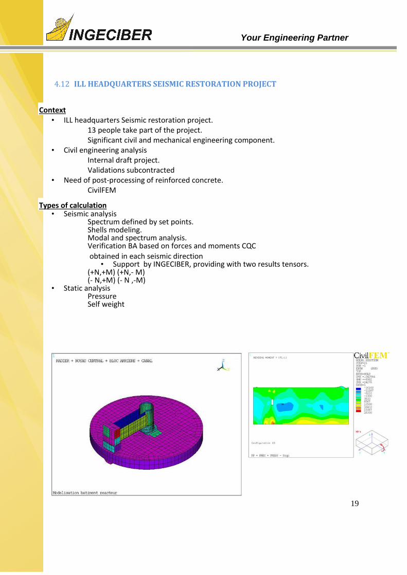
4.12 ILL HEADQUARTERS SEISMIC RESTORATION PROJECT
Context • ILL headquarters Seismic restoration project.
13 people take part of the project. Significant civil and mechanical engineering component.
• Civil engineering analysis
Internal draft project. Validations subcontracted
• Need of post-processing of reinforced concrete. CivilFEM
Types of calculation • Seismic analysis
Spectrum defined by set points. Shells modeling. Modal and spectrum analysis. Verification BA based on forces and moments CQC
obtained in each seismic direction • Support by INGECIBER, providing with two results tensors.
(+N,+M) (+N,- M) (- N,+M) (- N ,-M)
• Static analysis Pressure Self weight

20
Your Engineering Partner
4.13 FE MODEL OF A TRANSITION BALLASTLESS - BALLASTED TRACK
The goal of this study is to obtain the real value of the ballast stiffness as function of the
displacements measured as well as the behavior of the sleeper (i.e. stress distribution),
the influence of the check-rails as well as the different structural elements.
Two analysis types have been performed:
General model: The model consists in a section of the transition ballastless – ballasted
track. A dynamic transient analysis has been performed taking into account the
considerable dynamic effects.
Sleeper models: Static analysis of different detailed individual sleeper models have
been performed.

21
Your Engineering Partner
4.14 POWER PLANT MODEL. CHECK AND DESIGN ACCORDING TO CODES
Object
Power Plant Model. Check and design according to codes (in this case the
British codes were used)
Calculations Steps
Static and dynamic analysis of reactor buildings for nuclear power plants.
Static and dynamic analysis of turbine-generator foundations.
Loads combination with CivilFEM combination module.
Reinforcement of plates, walls and shells.
Local reinforcement around singularities.

22
Your Engineering Partner
4.15 SEISMIC ANALYSIS OF A CABLE TRAY SUPPORT
This analysis consists in a dynamic analysis of a structure system acting as cable tray
support.
Response Spectrum Analysis (RSA) has been performed to determine the transient
excitation due to an earthquake. The seismic analysis is characterize by the spectrum,
which is the response as function of the frequency.
The dynamic forces have been considered as well as static loads such as self-weight and
service loads.
Taking into account the results of the structural analyses, maximum displacement and
resultant stresses analysis have been performed in the trays and the supports as well as
in the bolts and the structure’s anchorage bolts with the goal of obtaining the
mechanical capacity and the measuring of the different structural elements of the
system.

23
Your Engineering Partner
4.16 STRUCTURAL ANALYSIS OF A FLOATING CAISSON ( BREAK WATER)
A 3D concrete floating voided caisson is modeled in order to optimise the thickness of
the concret elements and reinforcement amount. Different calculation models are
studied for each stage: transport, positioning, immersion and service.
The loads taken into account and the combined for ultimate and serviciability limit state
are the ones considering all stages including pressures due to immersed caisson
(ballasted with water or with sand) .
24
Your Engineering Partner
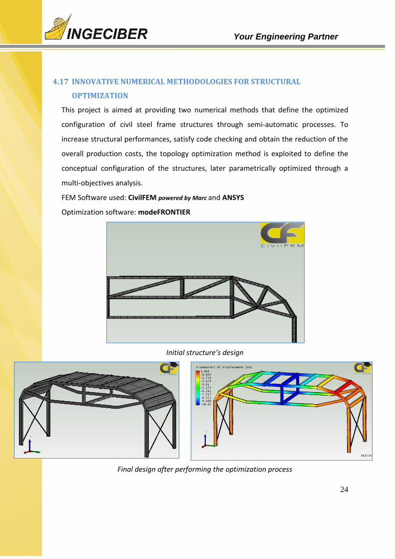
4.17 INNOVATIVE NUMERICAL METHODOLOGIES FOR STRUCTURAL
OPTIMIZATION
This project is aimed at providing two numerical methods that define the optimized
configuration of civil steel frame structures through semi-automatic processes. To
increase structural performances, satisfy code checking and obtain the reduction of the
overall production costs, the topology optimization method is exploited to define the
conceptual configuration of the structures, later parametrically optimized through a
multi-objectives analysis.
FEM Software used: CivilFEM powered by Marc and ANSYS
Optimization software: modeFRONTIER
Initial structure’s design
Final design after performing the optimization process

25
Your Engineering Partner
4.18 FIRE SIMULATION IN M-30 TUNNELS (MADRID)
M-30 is composed of two parallel underground tunnels over 50 meters that withstand a huge
transit of vehicles.
Ventilation inside the structure and proper evacuation of the smoke from a possible fire proved
vital.
The following calculations were made:
Simulation phases: 3D modelling of the ventilation system.
Transient simulation with variation of pulse energies and extraction based on the evolution of the fire.
Smoke spread simulation.
Analysis of results and corrective actions.

26
Your Engineering Partner
4.19 CFD VIBRATION ANALYSIS OF A HOWELL-BUNGER VALVE INSTALLED AT A
DAM
The goal of this study is to analyze using CFD techniques the hydraulic working of the Howell-
Bunger valve placed at the Aguilar de Campoo (Palencia) Dam, which is subjected to unusual
vibrations.
Three phases:
Phase 1: Study of the actual configuration of the pipe and the valve
Phase 2: Study of the pipe with some correcting measures (guides)
Phase 3: Optimization of the installation place of the guides
Guides installed in the pipe
Turbulences on the pipe
Pipe schema. The valve is placed at the outflow

27
Your Engineering Partner
FLOW-RATE MEASUREMENT IN THE CANAL OF MELONARES DAM (SEVILLA)
The purpose of this study was to obtain the depth-flow curves in the intake canal of the
Melonares dam. It is the first study of its kind conducted by a CFD model, without making a
reduced model.
Simulation phases:
3D model of the canal, from the pumping station.
Transient and multiphase simulation of pumping process to stabilize the flow in the system.
Results analysis and obtaining of the flow-rate measure curve.

28
Your Engineering Partner
4.20 FLOW AND AERATION STUDY IN A WWTP REACTOR
The design of a reactor of a Waste Water Treatment Plant (WWTP) has to focus towards
a uniform movement of sludge to prevent formation of prone to sedimentation and
proper aeration dead zones to encourage aerobic digestion of organic wastes. A design
raised in carousel reactor with an aeration system consisting of surface aerators, is
expected that the surface agitation of the sludge allow enter enough air into the device.
Phases:
Generation of three-dimensional geometric model of the WWTP reactor with flowing accelerators and surface shakers.
Fluid domain extraction, establish boundary conditions and fluids provided for installation devices.
As a result the flow characteristics established and dragging the oxygen introduced by surface
shakers shown. Aeration is very localized and insufficient, because below the surface there are
shakers much of the flow is not aerated.
Following this study finding alternative was approved for a more effective aeration.

29
Your Engineering Partner
4.21 WIND ACTION IN A WIND TURBINE FIELD
The aerodynamic behavior of a wind turbine field is
conditioned by the adjacent terrain. The register of the
wind in the zone is limited and the wind tunnel studies do
not capture the orography characteristics with the
presence of moving wind turbines.
To obtain more accurate and realistic results, tackling the
study with computational fluid dynamics (CFD) techniques
was proposed. The conventional software with their
traditional approach, based on the finite volumes method,
are not sufficient to accurately study such a big domain
with the presence of wind turbines in movement.
The software used was XFlow, with the assistance and
knowledge of the Mechanical Engineering and CFD
Department.
The topographic surface of the area was introduced in the
software and the 28 wind turbines which form the wind
turbine field were placed accurately. The extension of the
terrain studied was 432 km2. The rotation degree of
freedom of the blades was allowed and the wind was defined with a real wind profile of
the area. The adaptive refinement of the lattice allowed the capture of the movement
of the blades and their influence on the wind distribution.

30
Your Engineering Partner
4.22 WIND ACTION ON A SOLAR PLANT
Solar panels that make up a
solar plant are exposed to
weather actions, among which
are the strong winds that occur
occasionally. This was the case
of the solar garden in Vejer de la
Frontera, which in April 2011
suffered damage due to the
wind.
The case of study is the wind
around the solar array so that
checkpoints where
anemometers are placed get the
same values than those
observed in both speed and
wind direction. In this situation,
the wind speed on the exact
location of the solar plant and
solar panels affected is analyzed.
The results show that the surrounding orography alters the behavior of the wind and when the
conditions observed in April 2011 are reproduce , the solar farm area is swept by winds of over 115
km / h, which exceeds the design strength panels.
Phases:
Generation of three-dimensional geometric model of the terrain in the area of solar plant.
Imposition of boundary conditions that define the observed wind and verification by sensors
placed on the position of the reference anemometers.

31
Your Engineering Partner
4.23 ANALYSIS OF WIND EFFECT ON AN HELIOSTAT
The design and dimensioning of
equipment exposed to wind actions
requires a thorough aerodynamic
analysis. In the case of a heliostat, the
large size of the mirror determines its
wind resistance.
To address this analysis in time and
reasonable price, the best option is the
three-dimensional simulation using CFD
programs. Two situations were simulated:
the mirror in a vertical position subjected
to a wind of 100 km/h, and the mirror in
the safety position under a wind of 150
km/h.
Data of the drag, the tilting in the column
base, and lift force and torque turning of
the upper joint is obtained. These latest
actions come from the deflection of the
air flow when the mirror is folded.
Phases:
Adequacy of generating three-dimensional geometry and fluid surrounding the heliostat
domain.
Meshing of the fluid domain with special caution in the details of geometry and elements of
the boundary layer. The final calculation mesh consists of 22 million elements.
Definition of wind action conditions.
Resolution of the simulation and monitoring of the resultant forces.
Analysis of results and conclusions

32
Your Engineering Partner
4.24 CFD STUDY OF CHANNELING INFRASTRUCTURE
The predicted works for the
channeling of the water in
Argamasilla ravine included
different secondary streams. The
aim of the
channeling is to alleviate the
constant floods that regularly
affect the city of Écija (Sevilla).
The 2D simulation didn’t allow us
to tackle the complete channeling
analysis. Furthermore, it was
necessary to analyze the transient
evolution of the incoming flood
and not assume a steady state
flow. For this reason, a
tridimensional study of the
incoming flood was modeled with ANSYS-CFX, taking into account the elevated water
level in the Genil River, which is where the simulated channeling flows into.
The simulation shows the behavior of the flood in a transient regime, with a return
period of 50 years in the last section of the Argamasilla ravine channeling. The results
showed that the initially projected solution did not take into account the behavior of the
flood at the initial moment. When the flood finds its outlet blocked by the Genil River,
the water impacts against the upper wall and emerges through the upper ventilation
grids, creating a water jump which returns back through the internal part of the duct.
This study and its results were used for the correct installation redesign.

33
Your Engineering Partner
4.25 ADVANCE OF SEDIMENT PARTICLES DURING WASHING PROCESS IN A
STORM TANK
The construction of an underground storage tank for stormwater is projected. A high
level of fouling due to sedimentation while water is stored is envisaged. To lower
maintenance costs, a washing process is designed without the direct action of
operators, consisting of a sudden emptying of a depot situated at the top of the tank,
hoping the current to pull out and drag the sediments deposited.
In the first phase is studied the flood process caused by the discharge of header tank
Transient flow simulation allows determining the hydrograph of the flood, which is
shown superimposed on the image. Known the induced trawling by the flood, is
discretized spatially and temporally the phenomenon of entrainment of particles and
quantified progress in each state of the flow of the flood. The results showed that the
sediments are dragged from the first half of the tank, but these are accumulating at the
back and a few leave the tank.
Phases:
Generation of geometric model.
Transient study of flood flux.
Discretized study of particles advance
Quantifying the degree of final advance of the particles along the storm tank.

34
Your Engineering Partner
4.26 CFD STUDY OF A STORAGE AND PUMPING POOL
A deflector wall was placed at the entrance of a sea
water storage and pumping pool. To homogenize the
flux, two apertures were created in the sides of the
inflow catchment area. The operation of the pool
revealed a problem in the bottom covering just in
front of the lateral apertures. The objective of the
simulation was to determine the causes of the failure
and to determine the optimum operation level to
avoid the lateral flux damaging the covering.
A sequence of
CFD
simulations with
different operation modes was proposed,
varying only the water level on the pool. The
water level determines the mass of water in the
inflow catchment area. Its interaction with the
incoming flux disturbs the proportion of water which is alleviated through the lateral
apertures and the velocity of
this flux.
This study, which was
performed with ANSYS-CFX
allowed us to understand the
origin of the problem detected
and to define the optimum water level to guarantee the correct hydraulic behavior of
the pool.

35
Your Engineering Partner
4.27 ANALYSIS OF THE EVOLUTION OF AN EXPLOSION'S EXPANSIVE WAVE
The structural design of a building in an oil & gas plant has to take into account the
dynamic behavior of the building due to an expansive wave produced by a near
explosion.
The analysts have to measure the building to satisfy the codes. The critic point is to
know the time evolution of the over pressure pulses and the places of the building more
exposed.

36
Your Engineering Partner
4.28 SIMULATION OF TWO FIXED EFFLUENT AND ANALYSIS OF THE DILUTION
OF ITS SALT CONTENT
Plants for desalination of sea water
pouring require the extracted salt treated
water. In this process, it is necessary to
control the final discharge salinity
lowering it by mixing it with seawater.
The mixture of effluent with seawater in
the same pipe is not enough to
guarantee the complete homogenization
of salinity.
The objective is to simulate the mixing
of the effluent with sea water, taking into
account the geometry of the union and
the discharge pipe.
The analysis focuses on quantifying the evolution of salinity at each point of the pipeline. An added
difficulty is that the injection of the discharge
on the side of the pipe do not mix the two effluent because no turbulence is formed, and the
homogenization has to be produced by diffusion and stirring derived by the presence of bends in
the path of the pipe .
Simulation Phases:
3D model of a 250 m discharge pipe considering the blend placed at 50 m from injection
point.
Exhaustive meshing of the fluid domain with hexahedral elements that allow the collection
of all the details of the salt diffusion.
Application of models of particle concentration and diffusivity models.
Multiple simulations applying different salt concentrations and flow rates to represent
the different operating modes.
Analysis and quantification of mixed homogenization of salinity in the final discharge
37
Your Engineering Partner
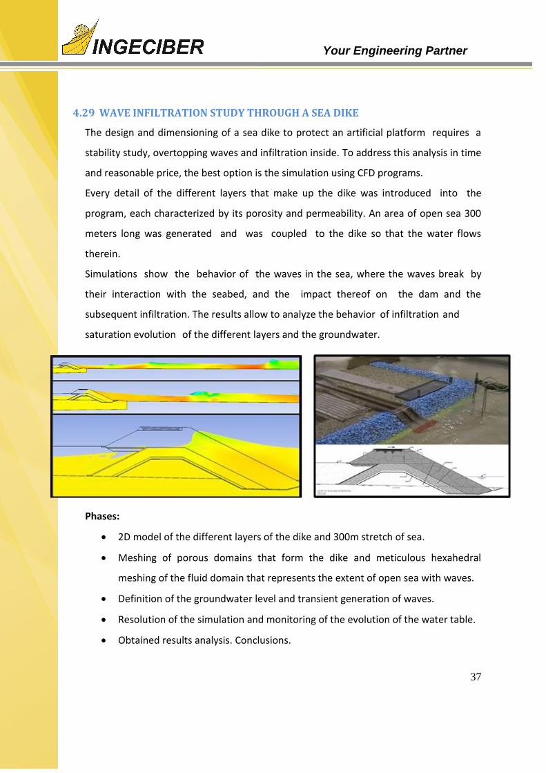
4.29 WAVE INFILTRATION STUDY THROUGH A SEA DIKE
The design and dimensioning of a sea dike to protect an artificial platform requires a
stability study, overtopping waves and infiltration inside. To address this analysis in time
and reasonable price, the best option is the simulation using CFD programs.
Every detail of the different layers that make up the dike was introduced into the
program, each characterized by its porosity and permeability. An area of open sea 300
meters long was generated and was coupled to the dike so that the water flows
therein.
Simulations show the behavior of the waves in the sea, where the waves break by
their interaction with the seabed, and the impact thereof on the dam and the
subsequent infiltration. The results allow to analyze the behavior of infiltration and
saturation evolution of the different layers and the groundwater.
Phases:
2D model of the different layers of the dike and 300m stretch of sea.
Meshing of porous domains that form the dike and meticulous hexahedral
meshing of the fluid domain that represents the extent of open sea with waves.
Definition of the groundwater level and transient generation of waves.
Resolution of the simulation and monitoring of the evolution of the water table.
Obtained results analysis. Conclusions.

38
Your Engineering Partner
4.30 FLOOD FLOW IN EL HIERRO RAVINE
The project consist in the channelling the final stretch in the ravine of El Hierro. A previous study with a linear program predicts a proper operation of the infrastructure. But its design with sharp changes of levels and curves, imposed by the natural layout of the ravine, make think that the results of a linear program cannot be apply.
A CFD simulation is planned with a transient 3D model. Hydrograph of the design flood is introduced. The multiphase simulation reveals the real behavior of flood in the infrastructure. The channeling gets pressure in several sections and water overflow in ventilation apertures. After the obtained results the construction of a channeling that does not meet the design criteria.
Phases:
Generation of three-dimensional geometric model of the entire channeling
and the aeration system.
Removing the fluid domain and meshing thereof with special caution in the
boundary layer meshing.
Imposition of boundary conditions that define the input flow of design flood.

39
Your Engineering Partner
Phases:
Generation of three-dimensional geometric model of the large pitcher and boxes of bombs.
Domain fluid extraction study.
Domain meshing with refinement of boundary layer.
Preparation of multiple technical solutions with different deflector walls
Definition of the boundary conditions which simulate the different operation modes.
Results comparison.
Design optimization of the deflector wall.
Validation of the solution adopted verifying its behavior in all modes of operation.
4.31 DESIGN OF A DEFLECTOR WALL IN A PUMPS HOUSE TO OPTIMIZE THE
FLUX
The modification of the mode of operation in a house of pumps is projected. The adding of a pump modify the flow established in the large pitcher and turbulence arising are sucked by the pumps compromising its operation.
.
Is planned a CFD simulation with a three-dimensional model showing the flow behavior of water in the pump housing and the different options for a deflector wall to optimize the overall performance, considering the various modes of operation raises the large pitcher and boxes of bombs. The results show how a small change in the length of the wall or on exit angle, alters the flow behavior across the large pitcher. After several iterations in the design process and analysis, the design of the baffle wall is optimized.