city of new westminster c/o durante kreuk ltd · june 22, 2010 our file: 110-2570 city of new...
TRANSCRIPT
June 22, 2010
Our File: 110-2570
CITY OF NEW WESTMINSTERc/o Durante Kreuk Ltd100 - 1152 Mainland Street,Vancouver, BC, V6B 4X2
Attention: Mr. Brian Beresford
Dear Sirs,
Re: Proposed Queensborough GreenwaysBoundary Canal, South Dyke Road and Stanley Street, New Westminster, BCGeotechnical Investigation Report
Attached, please find three copies of the geotechnical report for the proposed development to belocated at the above-stated address. This report summarizes the results of the subsurfaceinvestigation carried out at the above site on April 14, 15 and 19, 2010, and subsequentengineering analysis. In addition, this report provides geotechnical recommendations for the designand construction of the proposed development.
We trust this is sufficient for your current requirements. Please call if you have any questions, orif we can provide additional service.
Yours truly,
HORIZON ENGINEERING INC
Karen Savage, P.Eng.President

GEOTECHNICAL INVESTIGATION REPORT
for
Proposed Queensborough Greenway
at
Queensborough, New Westminster, BC
Our File: 110 - 2570
June 22, 2010
City of New Westminster c/o Durante Kreuk Our File: 110-2570Proposed Queensborough Greenway June 22, 2010Geotechnical Investigation Report
TABLE OF CONTENTS
PART A - BACKGROUND INFORMATION AND TECHNICAL DATA
1.0 INTRODUCTION . . . . . . . . . . . . . . . . . . . . . . . . . . . . . . . . . . . . . . . . . . . . . . . . . . . . . . 1
2.0 SITE DESCRIPTION and PROPOSED DEVELOPMENT . . . . . . . . . . . . . . . . . . . . . . . 12.1 Boundary Canal Greenway . . . . . . . . . . . . . . . . . . . . . . . . . . . . . . . . . . . . . . . . . 12.2 South Dyke Riverfront Greenway . . . . . . . . . . . . . . . . . . . . . . . . . . . . . . . . . . . . 12.3 Stanley Street Greenway . . . . . . . . . . . . . . . . . . . . . . . . . . . . . . . . . . . . . . . . . . 2
3.0 FIELD INVESTIGATION . . . . . . . . . . . . . . . . . . . . . . . . . . . . . . . . . . . . . . . . . . . . . . . . . 2
4.0 SUBSURFACE CONDITIONS . . . . . . . . . . . . . . . . . . . . . . . . . . . . . . . . . . . . . . . . . . . . 44.1 Boundary Canal Service Road . . . . . . . . . . . . . . . . . . . . . . . . . . . . . . . . . . . . . . 4
4.1.1 Topsoil . . . . . . . . . . . . . . . . . . . . . . . . . . . . . . . . . . . . . . . . . . . . . . . . . . . 44.1.2 Silty Sand (Fill) . . . . . . . . . . . . . . . . . . . . . . . . . . . . . . . . . . . . . . . . . . . . 44.1.3 Peat . . . . . . . . . . . . . . . . . . . . . . . . . . . . . . . . . . . . . . . . . . . . . . . . . . . . . 44.1.4 Organic Silt . . . . . . . . . . . . . . . . . . . . . . . . . . . . . . . . . . . . . . . . . . . . . . . 54.1.5 Silt . . . . . . . . . . . . . . . . . . . . . . . . . . . . . . . . . . . . . . . . . . . . . . . . . . . . . . 5
4.2 South Dyke Road Greenway . . . . . . . . . . . . . . . . . . . . . . . . . . . . . . . . . . . . . . . 54.2.1 Topsoil . . . . . . . . . . . . . . . . . . . . . . . . . . . . . . . . . . . . . . . . . . . . . . . . . . . 54.2.2 Sand to Silty Sand (Fill) . . . . . . . . . . . . . . . . . . . . . . . . . . . . . . . . . . . . . . 54.2.3 Sand with Trace Gravel . . . . . . . . . . . . . . . . . . . . . . . . . . . . . . . . . . . . . . 54.2.4 Silt . . . . . . . . . . . . . . . . . . . . . . . . . . . . . . . . . . . . . . . . . . . . . . . . . . . . . . 54.2.5 Peat . . . . . . . . . . . . . . . . . . . . . . . . . . . . . . . . . . . . . . . . . . . . . . . . . . . . . 54.2.6 Silt . . . . . . . . . . . . . . . . . . . . . . . . . . . . . . . . . . . . . . . . . . . . . . . . . . . . . . 64.2.7 Sandy Silt / Silty Sand . . . . . . . . . . . . . . . . . . . . . . . . . . . . . . . . . . . . . . . 64.2.8 Sand . . . . . . . . . . . . . . . . . . . . . . . . . . . . . . . . . . . . . . . . . . . . . . . . . . . . 6
4.3 Stanley Street Trail . . . . . . . . . . . . . . . . . . . . . . . . . . . . . . . . . . . . . . . . . . . . . . . 64.3.1 Topsoil . . . . . . . . . . . . . . . . . . . . . . . . . . . . . . . . . . . . . . . . . . . . . . . . . . . 64.3.2 Sand (Fill) . . . . . . . . . . . . . . . . . . . . . . . . . . . . . . . . . . . . . . . . . . . . . . . . 64.3.3 Silt . . . . . . . . . . . . . . . . . . . . . . . . . . . . . . . . . . . . . . . . . . . . . . . . . . . . . . 64.3.4 Peat . . . . . . . . . . . . . . . . . . . . . . . . . . . . . . . . . . . . . . . . . . . . . . . . . . . . . 64.3.5 Organic Silt . . . . . . . . . . . . . . . . . . . . . . . . . . . . . . . . . . . . . . . . . . . . . . . 74.3.6 Silt . . . . . . . . . . . . . . . . . . . . . . . . . . . . . . . . . . . . . . . . . . . . . . . . . . . . . . 7
4.4 Moisture Content . . . . . . . . . . . . . . . . . . . . . . . . . . . . . . . . . . . . . . . . . . . . . . . . . 74.5 Schematic Soil Profiles . . . . . . . . . . . . . . . . . . . . . . . . . . . . . . . . . . . . . . . . . . . . 74.6 Groundwater Conditions . . . . . . . . . . . . . . . . . . . . . . . . . . . . . . . . . . . . . . . . . . . 7
PART B - ENGINEERING ANALYSES
5.0 CONE PENETRATION TEST (CPT) ANALYSIS . . . . . . . . . . . . . . . . . . . . . . . . . . . . . . 85.1 Water Levels . . . . . . . . . . . . . . . . . . . . . . . . . . . . . . . . . . . . . . . . . . . . . . . . . . . . 85.2 Soil Behaviour Type . . . . . . . . . . . . . . . . . . . . . . . . . . . . . . . . . . . . . . . . . . . . . . 85.3 Standard Penetration Test (SPT) Correlation . . . . . . . . . . . . . . . . . . . . . . . . . . . 95.4 Undrained Shear Strength . . . . . . . . . . . . . . . . . . . . . . . . . . . . . . . . . . . . . . . . . 95.5 Overconsolidation Ratio . . . . . . . . . . . . . . . . . . . . . . . . . . . . . . . . . . . . . . . . . . . 9
6.0 SEISMIC ANALYSIS . . . . . . . . . . . . . . . . . . . . . . . . . . . . . . . . . . . . . . . . . . . . . . . . . . . 9

City of New Westminster c/o Durante Kreuk Our File: 110-2570Proposed Queensborough Greenway June 22, 2010Geotechnical Investigation Report
7.0 SOIL LIQUEFACTION POTENTIAL ANALYSIS . . . . . . . . . . . . . . . . . . . . . . . . . . . . . . 107.1 Post-Liquefaction Lateral Movements . . . . . . . . . . . . . . . . . . . . . . . . . . . . . . . . 107.2 Post-Liquefaction Settlements . . . . . . . . . . . . . . . . . . . . . . . . . . . . . . . . . . . . . 11
8.0 PILE ANALYSIS . . . . . . . . . . . . . . . . . . . . . . . . . . . . . . . . . . . . . . . . . . . . . . . . . . . . . . 118.1 Axial Bearing Capacity . . . . . . . . . . . . . . . . . . . . . . . . . . . . . . . . . . . . . . . . . . . 118.2 Pile Lateral Load Analysis . . . . . . . . . . . . . . . . . . . . . . . . . . . . . . . . . . . . . . . . . 11
8.2.1 Assumptions . . . . . . . . . . . . . . . . . . . . . . . . . . . . . . . . . . . . . . . . . . . . . 128.2.2 Analysis Results . . . . . . . . . . . . . . . . . . . . . . . . . . . . . . . . . . . . . . . . . . 12
9.0 STABILITY ANALYSIS . . . . . . . . . . . . . . . . . . . . . . . . . . . . . . . . . . . . . . . . . . . . . . . . . 13
PART C - CONCLUSIONS AND RECOMMENDATIONS
10.0 DISCUSSION . . . . . . . . . . . . . . . . . . . . . . . . . . . . . . . . . . . . . . . . . . . . . . . . . . . . . . . . 1410.1 Boundary Canal . . . . . . . . . . . . . . . . . . . . . . . . . . . . . . . . . . . . . . . . . . . . . . . . 14
10.1.1 Proposed Improvements . . . . . . . . . . . . . . . . . . . . . . . . . . . . . . . . . . . . 1410.2 South Dyke Road Greenway . . . . . . . . . . . . . . . . . . . . . . . . . . . . . . . . . . . . . . 1510.3 Stanley Street Trail . . . . . . . . . . . . . . . . . . . . . . . . . . . . . . . . . . . . . . . . . . . . . . 16
11.0 RECOMMENDATIONS . . . . . . . . . . . . . . . . . . . . . . . . . . . . . . . . . . . . . . . . . . . . . . . . . 1611.1 Excavations . . . . . . . . . . . . . . . . . . . . . . . . . . . . . . . . . . . . . . . . . . . . . . . . . . . . 1611.2 Foundations and Associated Subgrade Preparation . . . . . . . . . . . . . . . . . . . . 17
11.2.1 Pile Foundations for Piers and Type I Look-Outs . . . . . . . . . . . . . . . . . 1711.2.2 Abutments for Piers and Type I Look-Outs . . . . . . . . . . . . . . . . . . . . . . 1711.2.3 Spread Footings for Light Posts, Signs and Bollards . . . . . . . . . . . . . . 17
11.3 Pavement Structures and Associated Subgrade Preparation . . . . . . . . . . . . . . 1811.3.1 South Dyke Road Widening . . . . . . . . . . . . . . . . . . . . . . . . . . . . . . . . . 1811.3.2 South Dyke Concrete Sidewalk and Plazas . . . . . . . . . . . . . . . . . . . . . 1811.3.3 Stanley Street Pedestrian Trail . . . . . . . . . . . . . . . . . . . . . . . . . . . . . . . 1811.3.4 Boundary Canal Service Road . . . . . . . . . . . . . . . . . . . . . . . . . . . . . . . 1911.3.5 Boundary Canal Pedestrian Path . . . . . . . . . . . . . . . . . . . . . . . . . . . . . 20
11.4 Retention Structures . . . . . . . . . . . . . . . . . . . . . . . . . . . . . . . . . . . . . . . . . . . . . 20
12.0 REVIEW . . . . . . . . . . . . . . . . . . . . . . . . . . . . . . . . . . . . . . . . . . . . . . . . . . . . . . . . . . . . 20
13.0 CLOSURE . . . . . . . . . . . . . . . . . . . . . . . . . . . . . . . . . . . . . . . . . . . . . . . . . . . . . . . . . . 21
APPENDICES
APPENDIX A . . . . . . . . . . . . . . . . . . . . . . . . . . . . . . . . . . . . . . . . . . . . . . . . . . . . . . . . . FiguresAPPENDIX B . . . . . . . . . . . . . . . . . . . . . . . . . . . . . . . . . . . . . . . . . . . . . . . . . . Auger Hole LogsAPPENDIX C . . . . . . . . . . . . . . . . . . . . . . . . . . . . . CPT Interpretation and Analyses ResultsAPPENDIX D . . . . . . . . . . . . . . . . . . . . . . . . . . . . . . . . . . . . . . . . . . . . . . Pile Analysis Results

City of New Westminster Our File: 110-2570Proposed Queensborough Greenways June 22, 2010Geotechnical Investigation Report Page 1
PART A - BACKGROUND INFORMATION AND TECHNICAL DATA
1.0 INTRODUCTION
This document reports on the results of the field investigation carried out on April 14, 15 and 19,2010 and subsequent analyses, and provides geotechnical design and constructionrecommendations for the proposed development.
This report is prepared in accordance with our proposal dated January 20, 2010. A set ofarchitectural drawings including layout, plans and sections was provided to us by Durante KreukLtd (dated March 25, 2010) which describes the extent of the sites and conceptual designs.
2.0 SITE DESCRIPTION and PROPOSED DEVELOPMENT
The subject site is on Queensborough Island within the South Arm of the Fraser River in NewWestminster, BC. The City of New Westminster plans to design and implement new features forthe several sites in the subject neighborhood. Figure 1 in appendix A shows the locations of allthree sites on Queensborough neighborhood map. The sites associated with the subject projectand proposed features, as defined by Durante Kreuk and the City of New Westminster and asrefined by the project team, are described following:
2.1 Boundary Canal Greenway
Boundary Canal extends along the east side ofBoundary Road from Ewen Avenue southwardto South Dyke Road. Thompson’s Landing Parkis located northeast of the intersection of SouthDyke Road and Boundary Road Canal, and atthe west terminus of Salter Street.
The proposed greenway extends 400 metressouth of Ewen Avenue, along the east side ofBoundary Canal. The proposed greenway willcomprise a 4 meter wide walking path whichmay also act as a service road for earthworksactivities associated with regular dredging of theBoundary Canal. The proposed path / road willbe setback 2 metres from the east crest of theCanal embankment. Currently this area isvegetated with grass. The canal is about 3 metres deep and 15 metres wide, from crest to crest,with side slopes of 1 Vertical : 2 Horizontal above the current, water level and 1 Vertical : 1Horizontal below the water level, approximately. Currently, the depth of water is about 1 meter.
2.2 South Dyke Riverfront Greenway
Queensborough Island is surrounded by a 3.8m wide dyke reserve which protects the area fromflooding. South Dyke Road is located at the crest of the southern Queensborough Dyke. Thetopography along the South Dyke Road slopes slightly down toward the west and locally down tothe Fraser River. The dyke is approximately 2.2 to 2.4 metres high.
Boundary Canal (looking south)
City of New Westminster Our File: 110-2570Proposed Queensborough Greenways June 22, 2010Geotechnical Investigation Report Page 2
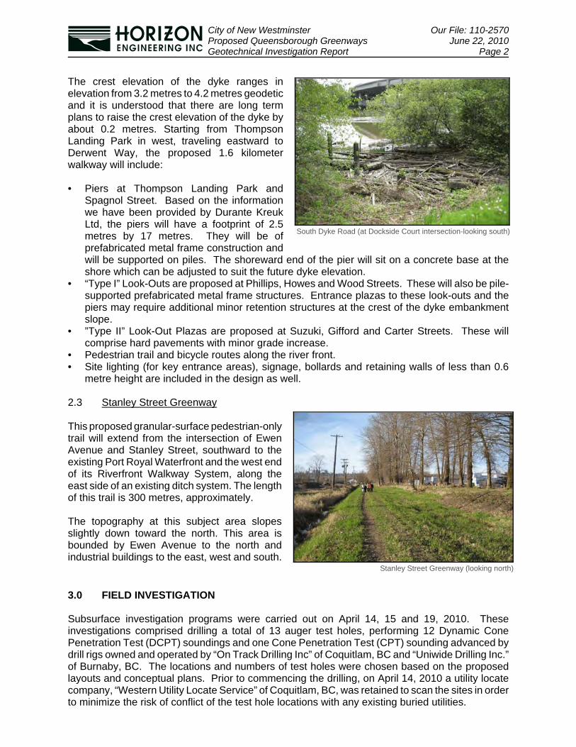
The crest elevation of the dyke ranges inelevation from 3.2 metres to 4.2 metres geodeticand it is understood that there are long termplans to raise the crest elevation of the dyke byabout 0.2 metres. Starting from ThompsonLanding Park in west, traveling eastward toDerwent Way, the proposed 1.6 kilometerwalkway will include:
• Piers at Thompson Landing Park andSpagnol Street. Based on the informationwe have been provided by Durante KreukLtd, the piers will have a footprint of 2.5metres by 17 metres. They will be ofprefabricated metal frame construction andwill be supported on piles. The shoreward end of the pier will sit on a concrete base at theshore which can be adjusted to suit the future dyke elevation.
• “Type I” Look-Outs are proposed at Phillips, Howes and Wood Streets. These will also be pile-supported prefabricated metal frame structures. Entrance plazas to these look-outs and thepiers may require additional minor retention structures at the crest of the dyke embankmentslope.
• ”Type II” Look-Out Plazas are proposed at Suzuki, Gifford and Carter Streets. These willcomprise hard pavements with minor grade increase.
• Pedestrian trail and bicycle routes along the river front.• Site lighting (for key entrance areas), signage, bollards and retaining walls of less than 0.6
metre height are included in the design as well.
2.3 Stanley Street Greenway
This proposed granular-surface pedestrian-onlytrail will extend from the intersection of EwenAvenue and Stanley Street, southward to theexisting Port Royal Waterfront and the west endof its Riverfront Walkway System, along theeast side of an existing ditch system. The lengthof this trail is 300 metres, approximately.
The topography at this subject area slopesslightly down toward the north. This area isbounded by Ewen Avenue to the north andindustrial buildings to the east, west and south.
3.0 FIELD INVESTIGATION
Subsurface investigation programs were carried out on April 14, 15 and 19, 2010. Theseinvestigations comprised drilling a total of 13 auger test holes, performing 12 Dynamic ConePenetration Test (DCPT) soundings and one Cone Penetration Test (CPT) sounding advanced bydrill rigs owned and operated by “On Track Drilling Inc” of Coquitlam, BC and “Uniwide Drilling Inc.”of Burnaby, BC. The locations and numbers of test holes were chosen based on the proposedlayouts and conceptual plans. Prior to commencing the drilling, on April 14, 2010 a utility locatecompany, “Western Utility Locate Service” of Coquitlam, BC, was retained to scan the sites in orderto minimize the risk of conflict of the test hole locations with any existing buried utilities.
South Dyke Road (at Dockside Court intersection-looking south)
Stanley Street Greenway (looking north)

City of New Westminster Our File: 110-2570Proposed Queensborough Greenways June 22, 2010Geotechnical Investigation Report Page 3
The approximate locations of the test holes arepresented in Figures 2 to 4 in Appendix A,attached following the text of this report. Table 1below describes the depths and locations of testholes on each site.
In accordance with the British ColumbiaGroundwater Protection Regulations (effectiveNovember 1, 2005), the auger test holes werebackfilled with drill cuttings complete with a "plug"that consisted of bentonite chips.
The drilling and testing operation was directedand supervised by an engineer from our office.The soil stratigraphy encountered at the test holeswas logged at the time of drilling and select soilsamples were retrieved from the auger flights and returned to our office for further examination andlaboratory tests.
A general description of the soil layers encountered follows in Section 4.0 and detailed descriptionsare presented in the Test Hole Logs (Appendix B).
Table 1: Depth and Locations of Auger Holes
Site Auger holeDepth (ft)
LocationDrilling DCPT Sounding
Boun
dary
Can
alG
reen
way
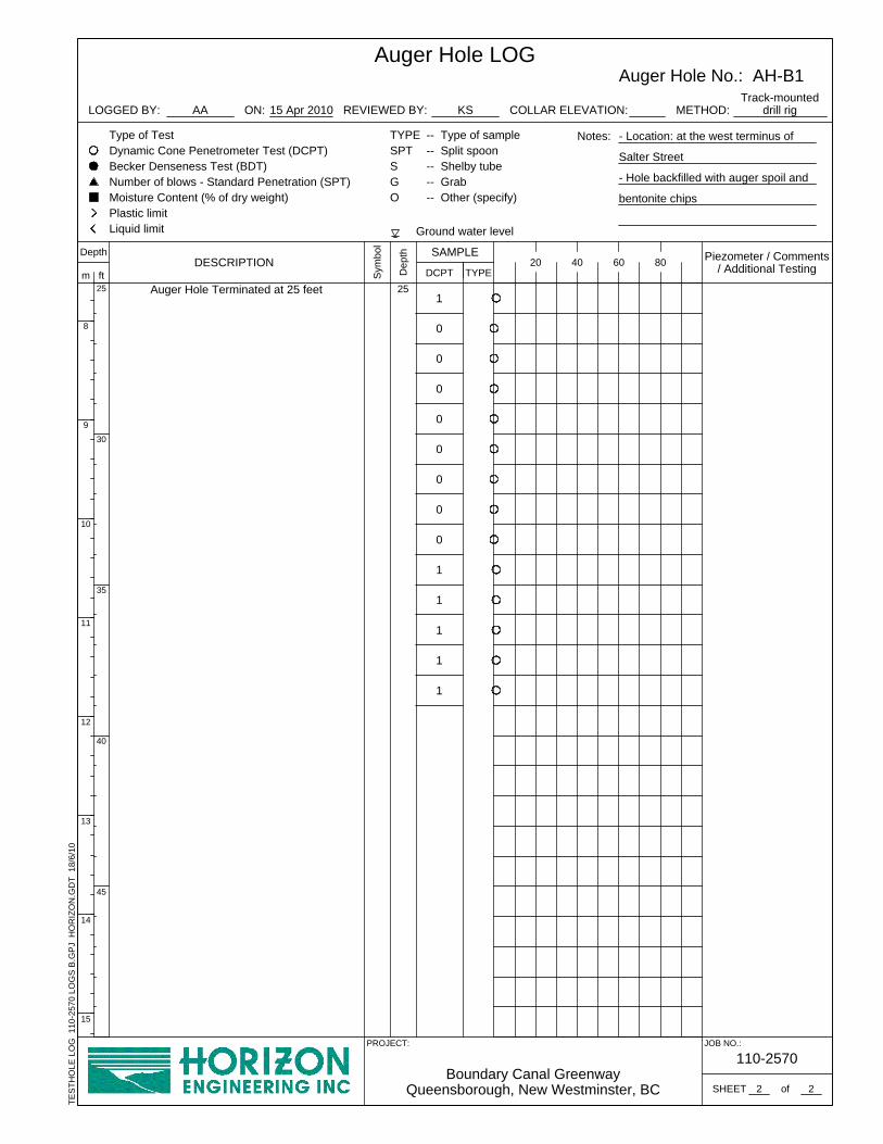
AH-B1 25 38 West terminus of Salter Street
AH-B2 25 43 East of 4456 Boundary Road
AH-B3a 20 -East of 4431 Boundary Road
AH-B3b 20 22
AH-B4 20 38 At southeast corner of Phillips Street and EwenAvenue
Sout
h D
yke
Roa
dG
reen
way
AH-SD1 35 42 South of Thompson Landing Park
AH-SD2 35 45 South Terminus of Phillips Street
AH-SD3 35 38 South Terminus of Spagnol Street
AH-SD4 15 17 South Terminus of Gifford Street
AH-SD5 10 17 South Terminus of Wood Street
Sta
nley
S
treet
Gre
enw
ay
AH-S1 15 22 North terminus of trail
AH-S2 15 12 At the middle of trail
AH-S3 15 17 South terminus of trail
Drilling at AH-SD1 location (looking west)

City of New Westminster Our File: 110-2570Proposed Queensborough Greenways June 22, 2010Geotechnical Investigation Report Page 4
The DCPT penetration resistance blow count values, or N60 blow count values, collected as part ofthe penetration testing are reported to be equivalent to Standard Penetration Test (SPT) blow countvalues (N) when collected using apparatus that is 60% energy efficient. The DCPT soundings wereadvanced to the maximum depth of the test holes or beyond.
The CPT sounding was carried out at the location of AH-SD2, to a maximum depth of 14.6 metreswhere continued penetration of electronic probe was not practical due to the density of the soilbeing penetrated at this depth.
4.0 SUBSURFACE CONDITIONS
Based on the published information from “GeologicalSurvey of Canada (published in 1971)”, the surficialgeology in the areas of the Stanley Street Trail andBoundary Canal Greenways mostly consists of bog,swamp and shallow lake deposits consisting of up to 14metres of lowland peat, overlying Fraser Riversediments. The southern portions of these sites areexpected to have 1 to 2 metres of peat.
According to the above-mentioned information, nativesoil at South Dyke Road and the southern portions ofthe above-stated greenways comprises deltaic anddistributary channel fill sediments overlying and cuttingestuarine sediments and overlain in part of the area byoverbank sediments which specifically consist of silty tosilt clay loam normally up to 2 metres thick overlying 15metres or more of channel fills (includes tidal flatdeposits).
Following is a summary of the soil layers encountered at the test hole locations. Subsurface soilconditions generally consisted of surficial fill underlain by peat and organic silt, in turn underlain bycompact to dense fine to medium grained sand.
4.1 Boundary Canal Service Road
4.1.1 Topsoil
A dry to moist, dark brown silt layer was encountered in all auger holes to a depth of about 0.2 to0.45 metres. This stratum contained trace to some organics (roots and rootlets) and is inferred tobe soft to firm.
4.1.2 Silty Sand (Fill)
A 250 mm thick, dry to moist, silty sand with trace gravel and occasional cobbles was encounteredin AH-B4 below the topsoil. This was inferred to be fill as is also contained occasional pieces ofplastic and garbage. This stratum was inferred to be compact.
4.1.3 Peat
A brown, amorphous / fibrous peat layer containing occasional decomposed wood fragments androotlets was encountered below the topsoil / fill in all auger holes. This stratum extended to 1.8 to4 metres below the existing ground surface.
Geology of the site

City of New Westminster Our File: 110-2570Proposed Queensborough Greenways June 22, 2010Geotechnical Investigation Report Page 5
Based on Dynamic Cone Penetration Test (DCPT) results, this layer is inferred to be very soft tosoft.
4.1.4 Organic Silt
A 1.5 to 2.4 meter thick, moist to wet, organic silt containing occasional wood fragments is overlainby above-mentioned peat layer in AH-B2 to AH-B4. Based on DCPT results, this material is inferredto be very soft.
4.1.5 Silt
The above-mentioned layers were underlain by a grey, plastic silt with some clay. This layercontains occasional peat inclusions and extends to the bottom of all the auger holes.
Based on DCPT results, this material is inferred to be very soft to soft.
4.2 South Dyke Road Greenway
4.2.1 Topsoil
This 0.15 to 0.2 meter thick, moist, sandy silt to silty sand layer was observed in almost all test holelocations (except AH-SD5). This layer contained trace to some organic material.
4.2.2 Sand to Silty Sand (Fill)
This layer was encountered at all test hole locations and extended to a depth of 2.1 to 2.4 metres.The upper portion of this layer consists of medium grained sand with some silt and trace to somegravel, while the lower portion mainly comprised silty sand with trace gravel and occasionalcobbles. This material is inferred to be compact to loose (becoming looser with depth).
4.2.3 Sand with Trace Gravel
A grey, medium to coarse grained sand with trace gravel was encountered in AH-SD2, AH-SD4 andAH-SD5 underlying the above-mentioned fill. The thickness of this layer varied from 0.6 to 0.75metres and is inferred to be loose to compact, according to DCPT blow counts.
4.2.4 Silt
This silt contained occasional peat inclusions and is encountered in all auger holes, underlying thefill and sand layers, as described above. The colour of this material varies from grey to browndepending on the amount of organic contained. In AH-SD4, interbedded sand layers wasencountered below a depth of 14.1 metres. Based on DCPT results in AH-SD4, this silt can beclassified as very soft to firm while in other auger holes, this material in inferred to be soft to firm.
Auger holes AH-SD4 and AH-SD5 were terminated within this silt material.
4.2.5 Peat
A brown, amorphous trace fibrous peat containing decomposed wood fragments was encounteredat the following depths along South Dyke Road:
‚ AH-SD1 between 5.0 to 7.2 metres ‚ AH-SD2 between 4.7 to 5.0 metres ‚ AH-SD3 between 5.2 to 6.2 metres

City of New Westminster Our File: 110-2570Proposed Queensborough Greenways June 22, 2010Geotechnical Investigation Report Page 6
Based on Dynamic Cone Penetration Test (DCPT) results, this layer is inferred to be soft to stiff.
4.2.6 Silt
A grey, plastic silt with some clay and occasional peat inclusions was encountered beneath the peatlayer in AH-SD1 and AH-SD2 extending down to 8.5 and 6.7 metres, respectively. In AH-SD3, thismaterial extended to the bottom of the auger hole (10.7 metres). This layer is inferred to be softto firm in AH-SD1 and AH-SD2 and stiff to very stiff in AH-SD3.
4.2.7 Sandy Silt / Silty Sand
In AH-SD1 and AH-SD2, a grey silty sand to sandy silt material is overlain by above-mentionedclayey silt layer and underlain by the sand layer as described in Section 4.2.3 above. According tothe particle size distribution of soil samples, this layer acts as a transition between the silt and sandlayers and based on DCPT blow counts it is inferred to be stiff to very stiff / loose to compact.
4.2.8 Sand
At AH-SD1 and AH-SD2, a grey, moist sand with trace to no silt was observed below a depth of10.2 and 9.6 metres, respectively. Based on DCPT blow counts, this material is compact. Blowcounts indicating a compact to very dense deposit extended beyond the 10.6 metre terminus depthof the auger holes. Based on deep drill holes done at nearby sites, this sand stratum may continueto a depth of at least 30 metres.
4.3 Stanley Street Trail
4.3.1 Topsoil
The entire area on the east side of the ditch is covered with an approximately 0.3 metres of darkbrown, moist, silty sand to sandy silt, containing trace to some organic (roots and rootlets).
4.3.2 Sand (Fill)
A very loose to loose, brown, fine to medium grained sand with trace to some gravel and trace tosome silt was encountered below the topsoil in AH-S1 and AH-S2 ; this is inferred to be fill.
4.3.3 Silt (Fill)
This grey mottled brown silt with trace fine-grained sand was observed in AH-S3, underlyingsurficial topsoil layer. Based on DCPT results, this material is inferred to be firm to very soft andaccording to our field observations, it does not seem to be naturally deposited in the subject site.
4.3.4 Peat
A brown peat layer is overlain by above-mentioned fill material in all test holes. The thickness of thislayer is 2.1 and 3.2 metres in AH-S1 and AH-S2, respectively. In AH-S3, this material extended tothe bottom of the test hole at 4.6 metres. According to Dynamic Cone Penetration Test results, thislayer is inferred to be very soft to soft.

City of New Westminster Our File: 110-2570Proposed Queensborough Greenways June 22, 2010Geotechnical Investigation Report Page 7
4.3.5 Organic Silt
Above-mentioned peat layer is underlain by organic silt containing occasional wood fragmentswhich extends to the bottom of borehole in AH-S3 location. Thickness of this stratum in AH-S1 andAH-S2 is 0.9 and 2.3 metres, respectively. According to in-situ DCP test results, this material isinferred to be very soft.
4.3.6 Silt
In AH-S1 and AH-S2, the above-mentioned peat layer was underlain by a very soft to soft, grey,plastic silt with some clay and occasional peat inclusions. This layer extended to the bottom ofauger holes.
4.4 Moisture Contents
A series of moisture content test (ASTM D2216-98) was carried out on select soil samples takenfrom auger holes. Test results are presented in Table 2 below:
Table 2: Summary of Moisture Content Test Results
Soil Layer MoistureContent (%)
Organic Silt 90 to 345
Silt 35 to 160
Sand / Silty Sand 10 to 60
Peat 215 to 470
4.5 Schematic Soil Profiles
Figure 5 attached to the text of this report (Appendix A) provides schematic geotechnical sectionsthrough auger holes at the subject sites. More details regarding the lithology of the soil layers andin-situ test results are presented in the borehole logs (Appendix B).
4.6 Groundwater Conditions
Groundwater was encountered in almost all auger holes. It is inferred that the depth of groundwateris affected by the level of water in adjacent ditches, canals and the Fraser River. Therefore,seasonal and possibly tidal ground water level fluctuation should be expected.
City of New Westminster Our File: 110-2570Proposed Queensborough Greenways June 22, 2010Geotechnical Investigation Report Page 8
PART B - ENGINEERING ANALYSES
5.0 CONE PENETRATION TEST (CPT) ANALYSIS
Cone Penetration sounding is a useful tool to allow interpretation of soil behaviour includingliquefaction potential, settlement characteristics and bearing capacity for relatively fine-grained, low-strength soil. One piezo-electric cone penetration test (CPT) was carried out adjacent to AH-SD2location (at the Phillips Street intersection) and advanced to a depth of approximately 14.6 metreswhere effective refusal was encountered. The electronic cone system used employs a 35.7 mmdiameter cone which records tip resistance (qC), sleeve friction (fS) and dynamic pore pressure (U2)at 20 to 60 mm intervals. Each reading is automatically recorded by a computer acquisition systemwired to the cone. The results of this CPT test in addition to the Dynamic Cone Penetration Tests(DCPT) results have been used to assess soil behaviour, liquefaction potential, and pile bearingcapacity and to estimate settlements. The results are discussed below and also plotted on the CPTseries of figures attached to this document (Appendix C).
5.1 Water Levels
CPT sounding provides a hydrostatic pressure reading when the piezo-electric cone probe ispassing through layers of coarser grained materials such as sand or sandy silt This allows anestimation of the local water table elevation (or depth). As the CPT equipment passes throughgranular soils, its temperature increases and the readings used to estimate groundwater level canbecome distorted. The deviation in pore pressure baseline between when the probe is inserted andwhen it is withdrawn gives an indication of the potential error in estimated water table depth.
The depth to the water table encountered at CPT-SD2 was 2.7 metres (9 feet) approximately, whichis reasonably consistent with the inferred groundwater level at the adjacent auger hole (AH-SD2)location.
5.2 Soil Behaviour Type
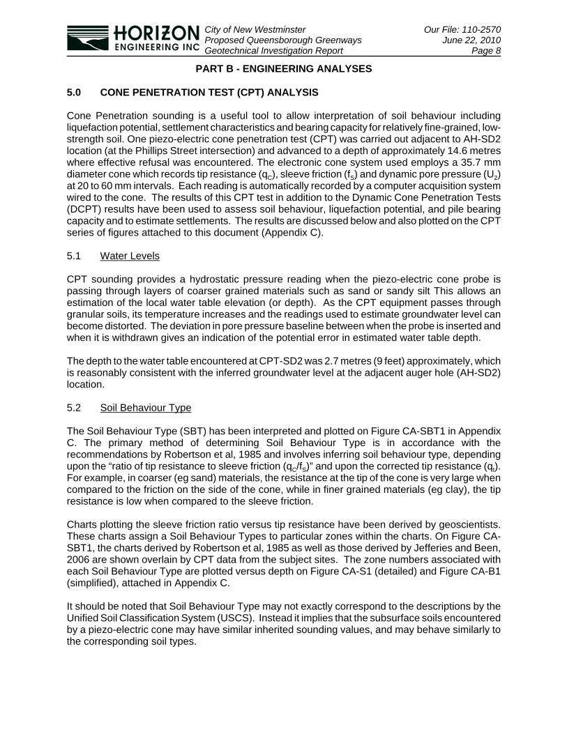
The Soil Behaviour Type (SBT) has been interpreted and plotted on Figure CA-SBT1 in AppendixC. The primary method of determining Soil Behaviour Type is in accordance with therecommendations by Robertson et al, 1985 and involves inferring soil behaviour type, dependingupon the “ratio of tip resistance to sleeve friction (qC/fS)” and upon the corrected tip resistance (qt).For example, in coarser (eg sand) materials, the resistance at the tip of the cone is very large whencompared to the friction on the side of the cone, while in finer grained materials (eg clay), the tipresistance is low when compared to the sleeve friction.
Charts plotting the sleeve friction ratio versus tip resistance have been derived by geoscientists.These charts assign a Soil Behaviour Types to particular zones within the charts. On Figure CA-SBT1, the charts derived by Robertson et al, 1985 as well as those derived by Jefferies and Been,2006 are shown overlain by CPT data from the subject sites. The zone numbers associated witheach Soil Behaviour Type are plotted versus depth on Figure CA-S1 (detailed) and Figure CA-B1(simplified), attached in Appendix C.
It should be noted that Soil Behaviour Type may not exactly correspond to the descriptions by theUnified Soil Classification System (USCS). Instead it implies that the subsurface soils encounteredby a piezo-electric cone may have similar inherited sounding values, and may behave similarly tothe corresponding soil types.
City of New Westminster Our File: 110-2570Proposed Queensborough Greenways June 22, 2010Geotechnical Investigation Report Page 9
5.3 Standard Penetration Test (SPT) Correlation
There is a generally accepted correlation between the Standard Penetration Test N60 and CPT tipresistance called the qc / N ratio for different soil types; this is well defined by Robertson, 1985. Theequivalent Standard Penetration Test blow counts at the CPT borehole are plotted on Figure CA-S1, in Appendix C.
5.4 Undrained Shear Strength
The undrained shear strengths of the fine grained, cohesive materials encountered in the CPTsounding have also be estimated using CPT data. These are plotted versus depth on Figure CA-S1 attached, following the text of this report. The undrained shear strength of the fine-grainedmaterial was found to be range from approximately 20 to 60 kPa.
5.5 Over-Consolidation Ratio
The over-consolidation ratio (OCR) is used to quantify the relationship between the maximum pastpressure applied to a compressible stratum and the pressure currently being applied. The OCR hasbeen estimated for fine-grained and coarse-grained material based on the correlations proposedby Powell et al, 1998 and Mayne 2005, respectively.
In fine grained soils, the ratio between undrained shear strength (Su) and effective vertical stress(σ’
v) at a given depth for normally consolidated material is assumed to be 0.22.
The CPT data analyses indicate that above an approximate depth of 4 metres, the OCR values areabove one, indicating over-consolidation likely due to the additional overburden pressure appliedto the subsurface layers during and after building the dyke.
In general, the material underlying the subject site are inferred to be normally consolidated toslightly over-consolidated.
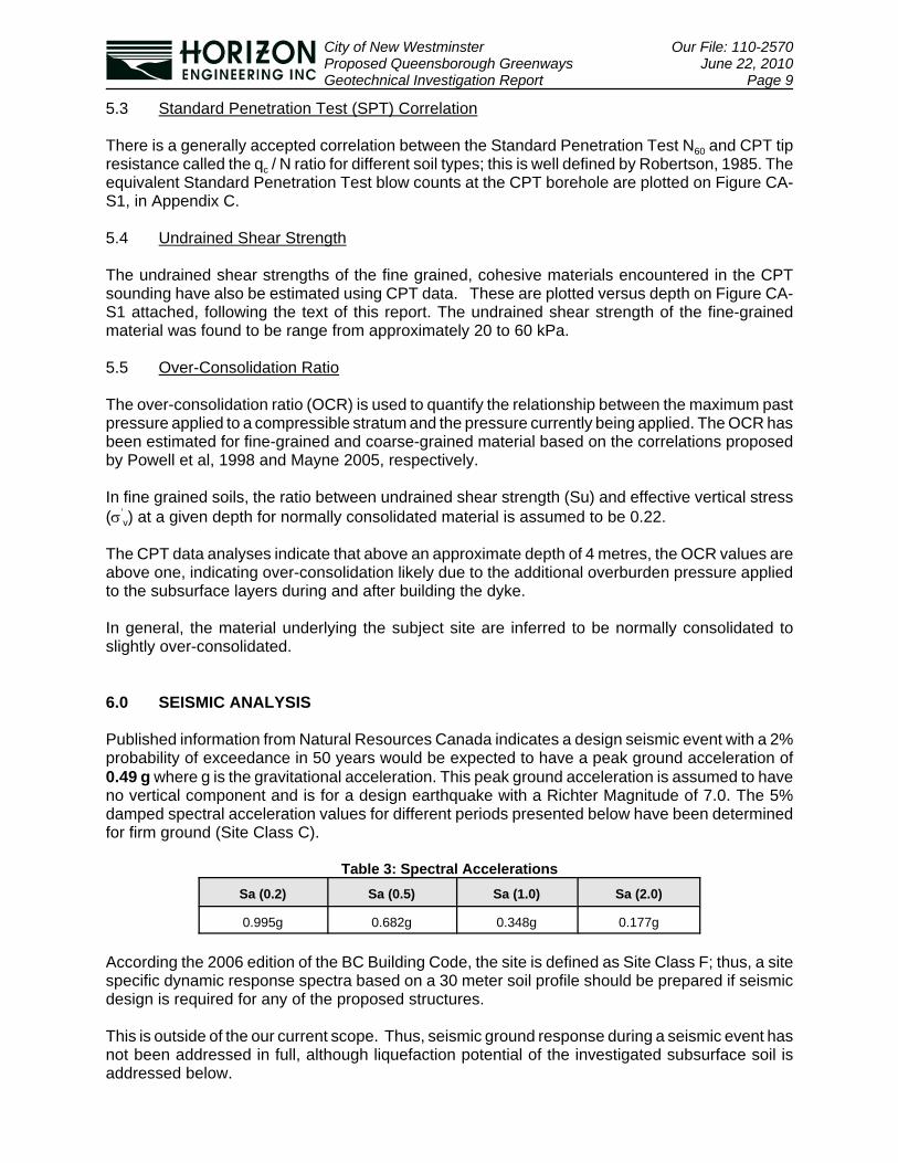
6.0 SEISMIC ANALYSIS
Published information from Natural Resources Canada indicates a design seismic event with a 2%probability of exceedance in 50 years would be expected to have a peak ground acceleration of0.49 g where g is the gravitational acceleration. This peak ground acceleration is assumed to haveno vertical component and is for a design earthquake with a Richter Magnitude of 7.0. The 5%damped spectral acceleration values for different periods presented below have been determinedfor firm ground (Site Class C).
Table 3: Spectral AccelerationsSa (0.2) Sa (0.5) Sa (1.0) Sa (2.0)
0.995g 0.682g 0.348g 0.177g
According the 2006 edition of the BC Building Code, the site is defined as Site Class F; thus, a sitespecific dynamic response spectra based on a 30 meter soil profile should be prepared if seismicdesign is required for any of the proposed structures.
This is outside of the our current scope. Thus, seismic ground response during a seismic event hasnot been addressed in full, although liquefaction potential of the investigated subsurface soil isaddressed below.
City of New Westminster Our File: 110-2570Proposed Queensborough Greenways June 22, 2010Geotechnical Investigation Report Page 10
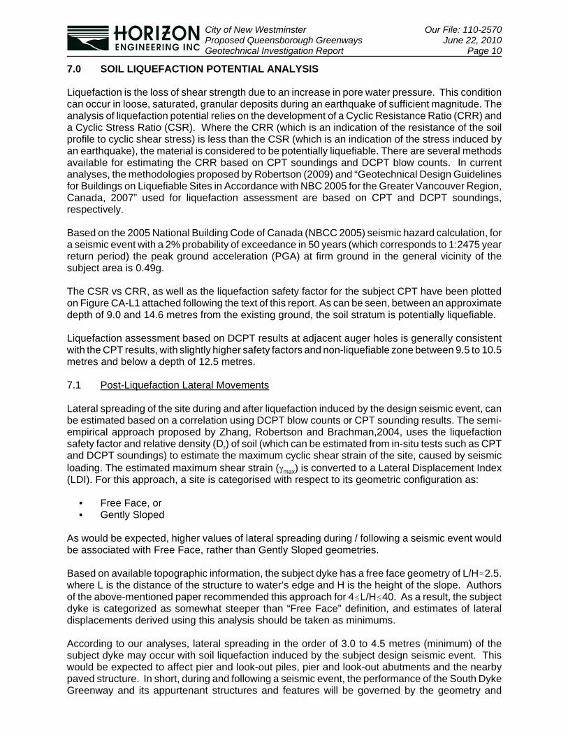
7.0 SOIL LIQUEFACTION POTENTIAL ANALYSIS
Liquefaction is the loss of shear strength due to an increase in pore water pressure. This conditioncan occur in loose, saturated, granular deposits during an earthquake of sufficient magnitude. Theanalysis of liquefaction potential relies on the development of a Cyclic Resistance Ratio (CRR) anda Cyclic Stress Ratio (CSR). Where the CRR (which is an indication of the resistance of the soilprofile to cyclic shear stress) is less than the CSR (which is an indication of the stress induced byan earthquake), the material is considered to be potentially liquefiable. There are several methodsavailable for estimating the CRR based on CPT soundings and DCPT blow counts. In currentanalyses, the methodologies proposed by Robertson (2009) and “Geotechnical Design Guidelinesfor Buildings on Liquefiable Sites in Accordance with NBC 2005 for the Greater Vancouver Region,Canada, 2007” used for liquefaction assessment are based on CPT and DCPT soundings,respectively.
Based on the 2005 National Building Code of Canada (NBCC 2005) seismic hazard calculation, fora seismic event with a 2% probability of exceedance in 50 years (which corresponds to 1:2475 yearreturn period) the peak ground acceleration (PGA) at firm ground in the general vicinity of thesubject area is 0.49g.
The CSR vs CRR, as well as the liquefaction safety factor for the subject CPT have been plottedon Figure CA-L1 attached following the text of this report. As can be seen, between an approximatedepth of 9.0 and 14.6 metres from the existing ground, the soil stratum is potentially liquefiable.
Liquefaction assessment based on DCPT results at adjacent auger holes is generally consistentwith the CPT results, with slightly higher safety factors and non-liquefiable zone between 9.5 to 10.5metres and below a depth of 12.5 metres.
7.1 Post-Liquefaction Lateral Movements
Lateral spreading of the site during and after liquefaction induced by the design seismic event, canbe estimated based on a correlation using DCPT blow counts or CPT sounding results. The semi-empirical approach proposed by Zhang, Robertson and Brachman,2004, uses the liquefactionsafety factor and relative density (Dr) of soil (which can be estimated from in-situ tests such as CPTand DCPT soundings) to estimate the maximum cyclic shear strain of the site, caused by seismicloading. The estimated maximum shear strain (γmax) is converted to a Lateral Displacement Index(LDI). For this approach, a site is categorised with respect to its geometric configuration as:
• Free Face, or • Gently Sloped
As would be expected, higher values of lateral spreading during / following a seismic event wouldbe associated with Free Face, rather than Gently Sloped geometries.
Based on available topographic information, the subject dyke has a free face geometry of L/H.2.5.where L is the distance of the structure to water’s edge and H is the height of the slope. Authorsof the above-mentioned paper recommended this approach for 4#L/H#40. As a result, the subjectdyke is categorized as somewhat steeper than “Free Face” definition, and estimates of lateraldisplacements derived using this analysis should be taken as minimums.
According to our analyses, lateral spreading in the order of 3.0 to 4.5 metres (minimum) of thesubject dyke may occur with soil liquefaction induced by the subject design seismic event. Thiswould be expected to affect pier and look-out piles, pier and look-out abutments and the nearbypaved structure. In short, during and following a seismic event, the performance of the South DykeGreenway and its appurtenant structures and features will be governed by the geometry and

City of New Westminster Our File: 110-2570Proposed Queensborough Greenways June 22, 2010Geotechnical Investigation Report Page 11
performance of the dyke.
It should be noted that, statistically, about 90% of the lateral displacements calculated using thisapproach, varied from 50% to 200% of measured values for the case histories studied. Therefore,the subject approach could underestimate or overestimate liquefaction-induced lateraldisplacements by up to a factor of 2.
7.2 Post-Liquefaction Settlements
Post-liquefaction settlements occur during and after earthquake shaking. For level groundconditions, the amount of post-liquefaction settlement can be computed from the volumetricreconsolidation strains induced as the excess pore water pressures dissipate. The amount ofvolumetric strain depends on density which in turn correlates to penetration resistance, and theCSR applied by the design earthquake. Curves proposed by Ishihara and Yoshimi, 1992 indicatethat volumetric reconsolidation strains can range from about 4.5% for very loose sand to 1.0% forvery dense sands.
Based on this methodology, post-liquefaction settlements are estimated to be in order of 200 mmfor level ground conditions.
It should be noted that this estimation corresponds to areas which are far enough from South DykeRoad so as to be considered level. Obviously in the case of slope failure at the dyke due to soilliquefaction, associated induced lateral spreading or global slope failure and vertical settlementswould be significant.
8.0 PILE ANALYSIS
8.1 Axial Bearing Capacity
The friction and end bearing capacity of timber and steel pipe piles have been estimated using CPTdata based on the methodology developed by Bustamante and Giasenelli,1982 also known as theLCPC method. Allowable axial bearing capacity is then calculated by applying appropriate factorsof safety to the ultimate friction and end bearing values. Figures CA-P1 and CA-P2 in AppendixD, present the ultimate and allowable axial capacities of select timber and steel pipe piles.
Due to the presence of thick, soft and compressible material with considerable organic content toa depth of approximately 8.5 to 9.1 metres (28 to 30 feet) below the existing ground (South DykeRoad elevation), the actual bearing layer which dictates the minimum pile length will be the FraserRiver sand present at a depth of approximately 10.7 metres (35.0 feet).
It should be noted that during the design earthquake, the above-mentioned sand layer is prone toliquefaction. Consequently, any pile foundation may lose lateral confinement and end bearing whichmay lead to excessive settlements and possibly failure.
8.2 Pile Lateral Load Analysis
For pile deformation analysis (for design of Look-Outs and Piers only), a commercially availablesoftware (LPILE version 5.0.41, by Ensoft Inc, USA) is used. Strength parameters of subsurfacesoil layers based on the subject subsurface investigation have been incorporated into the LPILEmodel.
In this analysis, timber piles and steel pipe piles of different sizes have been considered.

City of New Westminster Our File: 110-2570Proposed Queensborough Greenways June 22, 2010Geotechnical Investigation Report Page 12
8.2.1 Assumptions
The maximum axial pile load due to the weight of structure is considered to be 115 kN as providedby the structural engineer. We also understand that the maximum tolerable lateral deflection forpiles is about 100mm. The connection between the pile and the structure it supports is assumedto be pinned.
Debris loads have been provided by Northwest Hydraulic Consultants (Queensborough South DykePier/ Lookout Design Conditions Hydrotechnical Design Addendum 1-R2, dated May 31, 2010), fordifferent flood return periods. The 50-year return period (Q50) has been selected by the projectteam for design purposes. Based on the above mentioned report, the maximum horizontal loadapplied on a single pile corresponds to “Large individual log elements” and is estimated to be 310kN applied at elevation of 2.85m (GSC).
It should be noted that according to our discussion with the project team (including the structuralengineer - Glotman Simpson Consulting Engineers), since at least 2 piles are aligned with the riverflow direction, the above-mentioned load can be divided by 2, therefore the maximum lateral loadapplied to each individual pile is construed as 155 kN.
The modulus of elasticity of timber and steel piles are assumed to be 8.5 and 200 GPa,respectively.
8.2.2 Analysis Results
Based on above mentioned assumptions, timber piles seem to have excessive deflection and arelikely to fail under the design load. Therefore, for the purpose of piers and look-outs, steel pipe pilesare recommended. Table 3 below summarizes the appropriate options for steel pipe piles:
Table 4: Recommended Options for Steel Pipe PilesSteel Pipe Diameter (mm) Thickness
(mm) Schedule Approx.Deflection (mm)
Weight Per UnitLength (kg/m)*Outer Inner
457 410 23.8 #80 110 255
508 467 20.6 #60 90 248
559 533 12.7 XH 100 171
610 584 12.7 XH 80 187
* All pipe sizes and weights to be confirmed with pipe supplier and contractor
Deflection (Y), bending moment (M) and shear forces (V) along the depth of the piles for the abovecases have been plotted and are attached to the text of this report in Appendix D. It should be notedthat the generated forces along the piles should be compared with their corresponding allowablevalues, to assure that piles will not structurally fail under generated loads; these calculations shouldbe done by the structural engineer.
It should be noted that corrosion protection of piles should be considered and designed by others.We envisage losses of approximately 1.0 mm of thickness of the steel pipe piles for each 30 years.For example, the first 1.0 mm loss of thickness for a 22 inch-diameter pipe pile (559mm outerdiameter), is estimated to increase the lateral deflection of pile by 10%. Therefore, although the559mm OD pile would be an optimal pile choice if adequate corrosion protection could be appliedand maintained, the 610mm OD pile would be a choice that could accommodate the expectedamount of corrosion should no protection be applied.
City of New Westminster Our File: 110-2570Proposed Queensborough Greenways June 22, 2010Geotechnical Investigation Report Page 13
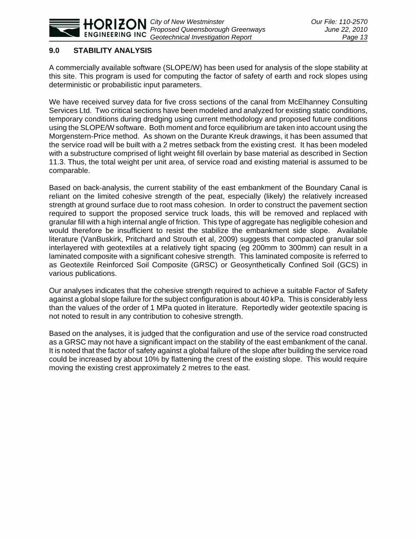
9.0 STABILITY ANALYSIS
A commercially available software (SLOPE/W) has been used for analysis of the slope stability atthis site. This program is used for computing the factor of safety of earth and rock slopes usingdeterministic or probabilistic input parameters.
We have received survey data for five cross sections of the canal from McElhanney ConsultingServices Ltd. Two critical sections have been modeled and analyzed for existing static conditions,temporary conditions during dredging using current methodology and proposed future conditionsusing the SLOPE/W software. Both moment and force equilibrium are taken into account using theMorgenstern-Price method. As shown on the Durante Kreuk drawings, it has been assumed thatthe service road will be built with a 2 metres setback from the existing crest. It has been modeledwith a substructure comprised of light weight fill overlain by base material as described in Section11.3. Thus, the total weight per unit area, of service road and existing material is assumed to becomparable.
Based on back-analysis, the current stability of the east embankment of the Boundary Canal isreliant on the limited cohesive strength of the peat, especially (likely) the relatively increasedstrength at ground surface due to root mass cohesion. In order to construct the pavement sectionrequired to support the proposed service truck loads, this will be removed and replaced withgranular fill with a high internal angle of friction. This type of aggregate has negligible cohesion andwould therefore be insufficient to resist the stabilize the embankment side slope. Availableliterature (VanBuskirk, Pritchard and Strouth et al, 2009) suggests that compacted granular soilinterlayered with geotextiles at a relatively tight spacing (eg 200mm to 300mm) can result in alaminated composite with a significant cohesive strength. This laminated composite is referred toas Geotextile Reinforced Soil Composite (GRSC) or Geosynthetically Confined Soil (GCS) invarious publications.
Our analyses indicates that the cohesive strength required to achieve a suitable Factor of Safetyagainst a global slope failure for the subject configuration is about 40 kPa. This is considerably lessthan the values of the order of 1 MPa quoted in literature. Reportedly wider geotextile spacing isnot noted to result in any contribution to cohesive strength.
Based on the analyses, it is judged that the configuration and use of the service road constructedas a GRSC may not have a significant impact on the stability of the east embankment of the canal.It is noted that the factor of safety against a global failure of the slope after building the service roadcould be increased by about 10% by flattening the crest of the existing slope. This would requiremoving the existing crest approximately 2 metres to the east.

City of New Westminster Our File: 110-2570Proposed Queensborough Greenways June 22, 2010Geotechnical Investigation Report Page 14
PART C - CONCLUSIONS AND RECOMMENDATIONS
10.0 DISCUSSION
In general, based on the results of the field investigation, although the challenging geotechnicalconditions will mandate expensive solutions in some areas and provided the followingrecommendations are incorporated into the design and construction of this project, the subject sitesare considered suitable for the proposed developments. Recommendations are provided for designand construction of the access roads, foundations and appurtenant features.
Any surcharge load due to new structures or increases in grade at Boundary Canal or StanleyStreet should be expected to cause excessive settlements, some of which would be differential.In addition, surcharge loads, including those due to construction loading conditions, may also causelocal instability and could lead to ground surface rupture and/or failure of the embankment atBoundary Canal. The amount of post-construction settlement can be reduced with a properlyphased and sequenced preloading program and/or strategic use of light weight fill. It is understoodthat the project schedule precludes the use of prelaoding. Differential settlement and the risk ofbearing failure can also be reduced by incorporating biaxial geogrid into structure subbases. Thereduction in differential settlement thus achieved will not preclude the requirement for ongoingmaintenance of pavement surfaces. Further, the strain required to transfer loads to some of thegeotextiles could be exhibited as surface movmeent which may also mandate maintenance.
Surcharge loads at South Dyke Road, including grade increases of more than 300 mm, should beassessed to ensure they do not affect dyke stability.
10.1 Boundary Canal
The soil stratigraphy at this site generally includes a shallow topsoil layer underlain by peat in turnunderlain by organic silt. The depth of the canal is 3 metres, thus the canal embankments are cutinto the peat and organic silt. Embankments are sloped at 1V: 2 H above the current water leveland 1V : 1H below the water level, approximately. It is understood that dredging of the canal isroutinely carried out using a Komatsu PC200 sitting at the crest of the east canal embankment, withsaturated spoil sidecast to the east. It is understood that track pressures for this machine mightrange up to 50 kPa (1000 psf). The history of embankments failures during this process isunknown. It is envisaged that the stability of the embankment slope during this process is afunction of operator skill and judgement. Further, based on a back analysis of this temporaryloading condition, it is envisaged that this stability is also highly dependent on root mass cohesionof the surficial grassy vegetation.
10.1.1 Proposed Improvements
It is understood that two scenarios are being considered to improve neighbourhood enjoyment ofthe Boundary Canal greenway. The first would see the area developed with a narrow path whichwould be subject to pedestrian loads only. With this, dredging operations would continue as-is withthe corresponding, operator-sensitive and questionable stability during the dredging process.
The second development option for Boundary Canal access would comprise development with aservice road capable of supporting vehicle loading. With this, the dredging operation would see thespoil removed from the area by dump truck. Significant live loads to the road surface would beexpected with this option.
City of New Westminster Our File: 110-2570Proposed Queensborough Greenways June 22, 2010Geotechnical Investigation Report Page 15
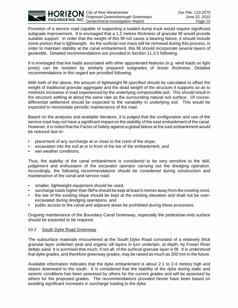
Provision of a service road capable of supporting a loaded dump truck would require significantsubgrade improvement. It is envisaged that a 1.2 metres thickness of granular fill would providesuitable support. In order that the weight of this fill not cause a bearing failure, it should includesome portion that is lightweight. As the surficial root mass will be removed during this process, inorder to maintain stability at the canal embankment, this fill should incorporate several layers ofgeotextile. Detailed recommendations are provided in Section 11.3.5 following.
It is envisaged that live loads associated with other appurtenant features (e.g. wind loads on lightposts) can be resisted by similarly prepared subgrades of lesser thickness. Detailedrecommendations in this regard are provided following.
With both of the above, the amount of lightweight fill specified should be calculated to offset theweight of traditional granular aggregate and the dead weight of the structure it supports so as tominimize increases in load experienced by the underlying compressible soil. This should result inthe structure settling at about the same rate as the surrounding natural soil surface. Of course,differential settlement should be expected to the variability in underlying soil. This would beexpected to necessitate periodic maintenance of the road.
Based on the analyses and available literature, it is judged that the configuration and use of theservice road may not have a significant impact on the stability of the east embankment of the canal.However, it is noted that the Factor of Safety against a global failure at the east embankment wouldbe reduced due to:
• placement of any surcharge at or close to the crest of the slope,• excavation into the soil at or in front of the toe of the embankment, and• wet weather conditions.
Thus, the stability of the canal embankment is considered to be very sensitive to the skill,judgement and enthusiasm of the excavator operator carrying out the dredging operation.Accordingly, the following recommendations should be considered during construction andmaintenance of the canal and service road:
• smaller, lightweight equipment should be used,• surcharge loads higher than 5kPa should be kept at least 5 metres away from the existing crest,• the toe of the existing slope should be kept at the existing elevation and shall not be over-
excavated during dredging operations, and• public access to the canal and adjacent areas be prohibited during these processes.
Ongoing maintenance of the Boundary Canal Greenway, especially the pedestrian-only surfaceshould be expected to be required.
10.2 South Dyke Road Greenway
The subsurface materials encountered at the South Dyke Road consisted of a relatively thickgranular layer underlain peat and organic silt layers in turn underlain, at depth, by Fraser Riverdeltaic sand. It is surmised that much, if not all, of the surficial granular layer is fill. It is understoodthat dyke grades, and therefore greenway grades, may be raised as much as 200 mm in the future.
Available information indicates that the dyke embankment is about 2.1 to 2.4 metres high andslopes downward to the south. It is considered that the stability of the dyke during static andseismic conditions has been assessed by others for the current grades and will be assessed byothers for the proposed grades. The recommendations provided herein have been based onavoiding significant increases in surcharge loading to the dyke.

City of New Westminster Our File: 110-2570Proposed Queensborough Greenways June 22, 2010Geotechnical Investigation Report Page 16
It has been assumed that the dyke has been designed by engineers with suitable field reviewscarried out during construction to assure a stable geometry under static and dynamic conditions(i.e. Q200 or M7) and suitable factor of safety for stability. Assessment of the impact of applying anysurcharge load induced by grade raise or structure loads on stability of the dyke, is beyond thescope of services of this report and should be carried out separately.
It should also be noted that the Fraser River deltaic sand deposit encountered at depth isconsidered to be prone to liquefaction in the event of a seismic event with a 2% chance ofexceedance in 50 years (i.e. the 2006 BC Building Code design event). As was discussed inSection 7.1, the geometry of the dyke supported on these liquefaction-prone deposits will governthe performance of the dyke, and nearby structures. Piles associated with structures at South DykeGreenway have not been designed to resist earthquake loads or displacements.
The two proposed piers and three proposed projected look-outs will be constructed of prefabricatedmetal sections supported on piles. The piles will be supported in end-bearing on the Fraser RiverDeltaic sand encountered at depth in AH-SD1 (near ‘Dockside Court’) and AH-SD2 (near ‘PhillipsStreet’).
In general, the thickness of granular soil comprising the dyke means that conventional roadsections and bollard, light post and signage foundations would be suitable. We have reviewed thetypical details for these items on the Durante Kreuk drawings for this project and judge them to beappropriate.
The recommendations regarding piled foundations, pavement and other appurtenant featuresassociated with the South Dyke Greenway are presented in the following sections.
10.3 Stanley Street Trail
For the purpose of this report, the subsurface conditions at the south portion of the Stanley Streettrail alignment can be considered geotechnically similar to those at South Dyke Road while theconditions at the north portion can be considered geotechnically similar to those at Boundary Canal.
11.0 RECOMMENDATIONS
11.1 Excavations
In general, it is recommended that unshored excavation slopes be no steeper than 1V:1H abovethe groundwater level and no steeper than 1V:4H below the water table. Based on the availableinformation, we do not envisage a requirement for excavations deeper than 1.2 metres (4 feet).
In addition, it is recommended that excavated spoil and construction materials be stockpiled nocloser than 1.5 and 8 metres (5 and 25 feet) to the crest of the excavation slopes in South DykeRoad and Boundary Canal material, respectively. Similar recommendation would apply to the southand north ends of the Stanley Street Greenway, respectively.
Grade adjacent to the excavation should be sloped to direct surface runoff away from theexcavation slopes. Horizon Engineering should review any excavation deeper than 1.2 metres (4feet) to ensure they are in conformance with Workers’ Compensation Board requirements and aresafe for worker access.
City of New Westminster Our File: 110-2570Proposed Queensborough Greenways June 22, 2010Geotechnical Investigation Report Page 17
11.2 Foundations and Associated Subgrade Preparation
Based on the information we have been provided by Durante Kreuk Ltd, we expect the followingtypes of foundation structures will be required for the proposed development:
• piles for piers and Type 1 look-outs• abutments for piers and Type 1 look-outs• spread footings for maximum 4 meter high light posts• spread footings for signs, and• spread or pedestal footings for bollards
11.2.1 Pile Foundations for Piers and Type 1 Look-Outs
Pile foundations are recommended for supporting Type 1 Look-Outs and piers along South DykeRoad. A wide range of pile types could be installed within these ground conditions. If piles areexposed to vertical loads only, timber piles may be used to transfer the loads to the subsurfacebearing layer. If axial and lateral loads (eg debris flood, etc) are expected to be applied to the piles,in order to attenuate the lateral deflection of the pile, use of steel pipe piles is recommended.
It should be noted that performance of the piles during a seismic event would essentially begoverned by the behavior of the dyke during the earthquake.
It is recommended to keep the minimum center to center spacing between piles as three times theirdiameter to prevent excessive pile settlements. Driving criteria for installation of any piles can bedetermined once the driving equipment has been determined. The bearing capacity of the above-mentioned pile types is described in Section 8.0. Full-time field review by the GeotechnicalEngineer is required during pile installation in order to confirm axial capacity.
It is envisaged that a 610mm OD steel pipe pile with a 12.7mm wall thickness would be suitably stiffto resist the specified lateral hydrodynamic forces during the design flood condition and have alateral displacement less than that recommended by the structural engineer, even allowing for theamount of corrosion estimated to occur during its design life.
11.2.2 Abutments for Piers and Type 1 Look-Outs
The shoreward end of piers and Type 1 Look-Outs may be supported by Lock Block abutments ifthe existing embankment slope is 1 Vertical : 2 Horizontal or less. Otherwise, it may be appropriateto support this shoreward end on piles.
11.2.3 Spread Footings for Light Posts, Signs and Bollards
Typical footing details would be appropriate for light posts, signs and bollards located on the SouthDyke Greenway and the south portion of the Stanley Street Greenway. These footings should beconstructed at a minimum depth of 450mm on the existing fills. Slight subexcavation may berequired to remove surficial topsoil.
At the Boundary Canal Greenway and where less than 600mm of existing granular fill is locatedbeneath proposed feature footings at the north portion of the Stanley Street Greenway, spreadfootings will be required. These footings should be designed using a bearing pressure of 15 kPaand constructed on a 600mm thickness of lightweight fill underlain by a layer of filter fabric andincorporating a layer of BX1400 MSE biaxial geogrid.

City of New Westminster Our File: 110-2570Proposed Queensborough Greenways June 22, 2010Geotechnical Investigation Report Page 18
Based on loading information provided by the structural engineer, it is understood that the width ofthe spread foundation will be 2 metres. The footprint of prepared subgrade should extend 1 metrebeyond the foundation footprint.
11.3 Pavement Structures and Associated Subgrade Preparation
Based on the information we have been provided by Durante Kreuk Ltd, we expect the followingtypes of pavement structures will be required for the proposed development:
• plazas for Type 2 Look-Outs at South Dyke Greenway• asphalt paved road widening for South Dyke Greenway• concrete sidewalk for South Dyke Greenway• pedestrian trail for Stanley Street Greenway, and• service road for Boundary Canal Greenway or• pedestrian path for Boundary Canal Greenway.
11.3.1 South Dyke Road Widening
The minimum pavement section required by the City of New Westminster:
Table 5: Recommended Minimum Asphalt Pavement Structure
Material Thickness(mm)
Asphaltic Concrete 100
¾ inch minus crushed sand and gravel base course 100
4 inch minus, well-graded, clean river sand, or sand andgravel subbase course 300
is judged suitable for widening of South Dyke Road. Existing topsoil should be removed prior toplacement of this pavement section. Stripped subgrades should be approved by the GeotechnicalEngineer prior to placing new fills.
Base and sub-base courses should be compacted to greater than 100% of their Maximum DryDensity when determined in accordance with ASTM D698. Field density test results should beforwarded in a timely fashion to the Geotechnical Engineer for review.
11.3.2 South Dyke Concrete Sidewalk and Plazas
We have reviewed the Durante Kreuk drawings and their typical section for concrete sidewalks andplazas comprised of 100mm of cast-in-place concrete underlain by 135mm of compacted granularbase, is judged suitable. Stripped subgrades should be approved by the Geotechnical Engineerprior to placing the base course and this material should be compacted to greater than 100% of itsMaximum Dry Density when determined in accordance with ASTM D698. Field density test resultsshould be forwarded in a timely fashion to the Geotechnical Engineer for review.
11.3.3 Stanley Street Pedestrian Trail
It is understood that proposed grades at the Stanley Street Greenway pedestrian trail will be up to400 mm above the existing grade. The recommended section for this trail, including subgradeimprovement is:
City of New Westminster Our File: 110-2570Proposed Queensborough Greenways June 22, 2010Geotechnical Investigation Report Page 19
Table 6: Recommended Stanley Street Pedestrian Trail Structure
Material Thickness(mm)
crushed limestone or grasscrete surface course 150
¾ inch minus crushed rock base course 150
filter fabric
lightweight fill sub-base courseincorporating one layer of BX1400 MSE biaxial geogrid 600
filter fabric
Compaction of the base and sub-base courses should be with a 500 pound plate tamper.Compaction procedures and results should be reviewed and approved by the GeotechnicalEngineer.
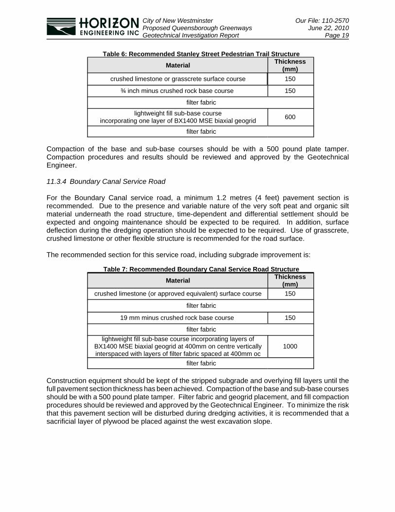
11.3.4 Boundary Canal Service Road
For the Boundary Canal service road, a minimum 1.2 metres (4 feet) pavement section isrecommended. Due to the presence and variable nature of the very soft peat and organic siltmaterial underneath the road structure, time-dependent and differential settlement should beexpected and ongoing maintenance should be expected to be required. In addition, surfacedeflection during the dredging operation should be expected to be required. Use of grasscrete,crushed limestone or other flexible structure is recommended for the road surface.
The recommended section for this service road, including subgrade improvement is:
Table 7: Recommended Boundary Canal Service Road Structure
Material Thickness(mm)
crushed limestone (or approved equivalent) surface course 150
filter fabric
19 mm minus crushed rock base course 150
filter fabriclightweight fill sub-base course incorporating layers of
BX1400 MSE biaxial geogrid at 400mm on centre verticallyinterspaced with layers of filter fabric spaced at 400mm oc
1000
filter fabric
Construction equipment should be kept of the stripped subgrade and overlying fill layers until thefull pavement section thickness has been achieved. Compaction of the base and sub-base coursesshould be with a 500 pound plate tamper. Filter fabric and geogrid placement, and fill compactionprocedures should be reviewed and approved by the Geotechnical Engineer. To minimize the riskthat this pavement section will be disturbed during dredging activities, it is recommended that asacrificial layer of plywood be placed against the west excavation slope.

City of New Westminster Our File: 110-2570Proposed Queensborough Greenways June 22, 2010Geotechnical Investigation Report Page 20
11.3.5 Boundary Canal Pedestrian Path
If the City of New Westminster elects to service the Boundary Canal from its west side (ie fromBoundary Road), and the proposed Boundary Canal Greenway will support pedestrian loads only,then a surface course of 150 mm crushed limestone is recommended. This surface course maybe placed on a layer of biaxial geogrid placed over the existing grass once it has been close-cropped. This work should be done by hand or using light weight construction equipment only.
11.4 Retention Structures
It is understood that retention structures are only proposed for South Dyke Greenway and that theywill comprise Deltalok assemblies of height 0.6 metres or less at the existing crest-of-dyke. Asthese walls are less than 1 meter in height, they will not require engineering design. However, oncedetailed topographic information is available for the dyke embankment, it should be confirmed thatthey have negligible impact on the global stability of this slope.
Should higher walls be deemed to be required, they will require detailed engineering designincluding global stability analysis, confirmation that the required bearing capacity is available, andan assessment of the impact of the surcharge load on the soft foundation subgrade soil beneaththe dyke.
12.0 REVIEW
For this project, geotechnical field reviews are recommended for the following items or during thefollowing stages of construction:
• to evaluate the safety of any excavations,• to confirm the suitability of stripped subgrades for South Dyke pavements and foundations,• to review the installation of piles (full time),• to review the placement and compaction of South Dyke pavement base and sub-base courses,• to review the placement procedures for Boundary Canal geosynthetics and fills, and• to review the compaction procedures for Boundary Canal fills.
In addition, any field density test results should be forwarded in a timely manner to HorizonEngineering for review.
It should be noted that the recommendations provided in this report are based on the informationprovided to us prior to and during preparation of the report. If any of these assumptions are revisedor new information becomes available, these recommendations should be reviewed by HorizonEngineering.
It is expected that such new information would include, but not be limited to, detailed topographicinformation at the dyke, structural loads and foundation sizes for the Boundary Canal light posts,signs and bollards.
As noted previously, for the purpose of this report, the subsurface conditions at the south portionof the Stanley Street trail alignment can be considered geotechnically similar to those at SouthDyke Road while the conditions at the north portion can be considered geotechnically similar tothose at Boundary Canal. This should be considered in terms of the above-noted geotechnicalreview and field review items.
City of New Westminster Our File: 110-2570Proposed Queensborough Greenways June 22, 2010Geotechnical Investigation Report Page 21
13.0 CLOSURE
This report has been prepared for the sole use of our client and other consultants for this project,as described. Any use or reproduction of this report for other than the stated intended purpose isprohibited without the written permission of Horizon Engineering Inc.
We are pleased to be of assistance to you on this project and we trust that our comments andrecommendations are both helpful and sufficient for your current purposes. If you would like furtherdetails or require clarification of the above, please do not hesitate to call.
For: For:HORIZON ENGINEERING INC. HORIZON ENGINEERING INC.
Karen Savage, P.Eng. Alireza Afkhami-Aghda, M.A.Sc.President Project Engineer
Attachments: Appendix A: Figures (5 pages)Appendix B: Test Hole Logs (19 pages)Appendix C: CPT Interpretation and Analyses (4 pages)Appendix D: Pile Analysis Results (3 pages)
N:\2010 Projects\110-2570 Queensborough Dyke\Report\110-2570 NWS Queensborough Greenway Report 22June10 kes.wpd
City of New Westminster c/o Durante Kreuk Our File: 110-2570Proposed Queensborough Greenway June 18, 2010Geotechnical Investigation Report Appendices
APPENDIX A
Figures

Scale:
Des: Dwn:
Job No: Date:
Chk: Rev:
FIGURE:
511 Royal Avenue, New Westminster, BC SITELOCATION NTS 110-2570 April/2010
AA MY KS 0 1

Scale:
Des: Dwn:
Job No: Date:
Chk: Rev:
FIGURE:
511 Royal Avenue, New Westminster, BC
TEST HOLELOCATION
PLAN(STANLEY St.)
NTS 110-2570 April/2010
AA MY KS 0 2

Scale:
Des: Dwn:
Job No: Date:
Chk: Rev:
FIGURE:
511 Royal Avenue, New Westminster, BC
TEST HOLELOCATION
PLAN NTS 110-2570 April/2010
AA MY KS 0 3


City of New Westminster c/o Durante Kreuk Our File: 110-2570Proposed Queensborough Greenway June 18, 2010Geotechnical Investigation Report Appendices
APPENDIX B
Auger Hole Logs

1
TES
THO
LE L
OG
110
-257
0 LO
GS
B.G
PJ
HO
RIZ
ON
.GD
T 2
1/6/
10
0
0
0
0
1
0
1
0
0
0
0
0
1
1
1
1
0
0
0
0
G 1
1
3
Moisture content:214%
0
Groundwater levelmeasured on Apr 19,2010
ORGANIC SILT (grey)plastic, trace clay, trace fine grained sand,
occasional peat inclusions, wet
- inferred to be very soft
PEAT (brown)amorphous some fibrous (including
occasional wood fragments), moist towet
- inferred to be very soft
TOPSOIL - SILT (dark brown)trace organics (rootlets), dry to moist
- inferred to be soft
G 2
Moisture content:471%
13
11
Dep
th SAMPLE
TYPESPTSGO
Type of TestDynamic Cone Penetrometer Test (DCPT)Becker Denseness Test (BDT)Number of blows - Standard Penetration (SPT)Moisture Content (% of dry weight)Plastic limitLiquid limit
REVIEWED BY: KS
20
Sym
bol
Boundary Canal GreenwayQueensborough, New Westminster, BC
110-2570
40
Auger Hole No.: AH-B1Auger Hole LOG
Track-mounteddrill rig
PROJECT:
LOGGED BY:
DCPT60
Ground water level
1
JOB NO.:
Depth
0
5
10
15
20
SHEET
80DESCRIPTIONft
15 Apr 2010
TYPE
Notes:
0
1
2
3
4
5
6
7
2
METHOD:
- Location: at the west terminus of
Salter Street
- Hole backfilled with auger spoil and
bentonite chips
Piezometer / Comments/ Additional Testing
ON: COLLAR ELEVATION:AA
m
-- Type of sample-- Split spoon-- Shelby tube-- Grab-- Other (specify)
of
DESCRIPTIONft
15 Apr 2010
SHEET
Auger Hole Terminated at 25 feetTYPE
of
80Depth
25
0
1
1
1
1
1
0
0
0
0
0
0
0
1
SAMPLE
Ground water level
-- Type of sample-- Split spoon-- Shelby tube-- Grab-- Other (specify)
DCPT
TYPESPTSGO
Type of TestDynamic Cone Penetrometer Test (DCPT)Becker Denseness Test (BDT)Number of blows - Standard Penetration (SPT)Moisture Content (% of dry weight)Plastic limitLiquid limit
REVIEWED BY:
Auger Hole No.: AH-B1Auger Hole LOG
Track-mounteddrill rig
PROJECT:
LOGGED BY:
60
2
20
KS
- Location: at the west terminus of
Salter Street
- Hole backfilled with auger spoil and
bentonite chips
METHOD:
Piezometer / Comments/ Additional Testing
2
ON: COLLAR ELEVATION:AA
TES
THO
LE L
OG
110
-257
0 LO
GS
B.G
PJ
HO
RIZ
ON
.GD
T 1
8/6/
10
Notes:
m Dep
th
Sym
bol
Boundary Canal GreenwayQueensborough, New Westminster, BC
40
110-2570JOB NO.:
25
30
35
40
45
8
9
10
11
12
13
14
15

0
0
0
0
1
0
0
1
1
0
0
0
4
2
4
2
4
6
6
0
TES
THO
LE L
OG
110
-257
0 LO
GS
B.G
PJ
HO
RIZ
ON
.GD
T 2
1/6/
10
G 1
2
1
5
3
4
12
Groundwater levelmeasured on Apr 15,2010
SILT (grey)plastic, some clay, trace fine grained sand,
trace organics, occasional peatinclusions, wet
- inferred to be very soft above 20 ft and softto firm below
ORGANIC SILT (brown)occasional wood fragments, moist to wet
- inferred to be very soft
PEAT (greyish brown)amorphous some fibrous (including
occasional wood fragments), moist towet
- inferred to be very soft
SILT (brown)trace fine-grained sand, trace gravel, trace
organics, occasional cobbles, moist towet
- inferred to be soft to firm- inferred to be fill
TOPSOIL - SILT (dark brown)trace organics (rootlets), dry to moist
- inferred to be firm
G 3
G 2
7
4
0.67
Boundary Canal GreenwayQueensborough, New Westminster, BC
SAMPLE
TYPESPTSGO
Type of TestDynamic Cone Penetrometer Test (DCPT)Becker Denseness Test (BDT)Number of blows - Standard Penetration (SPT)Moisture Content (% of dry weight)Plastic limitLiquid limit
REVIEWED BY: KS
4020
0
1
2
3
4
5
6
7
Sym
bol
110-2570JOB NO.:
Dep
th
Auger Hole No.: AH-B2Auger Hole LOG
Track-mounteddrill rig
PROJECT:
LOGGED BY:
DCPT60
Ground water level
0
5
10
15
20
1
DESCRIPTIONDepth
SHEET
ft
15 Apr 2010
TYPE80
- Location: across 4456 Boundary
Road
- Hole backfilled with auger spoil and
bentonite chips
Notes:
Piezometer / Comments/ Additional Testing
ON: COLLAR ELEVATION: METHOD:AA
2
m
-- Type of sample-- Split spoon-- Shelby tube-- Grab-- Other (specify)
of

9
TYPE80
Auger Hole Terminated at 25 feet
Depth
SHEET
DESCRIPTIONft
15 Apr 2010
10
25
6
8
7
7
8
6
6
6
6
6
5
5
4
6
4
4
6
Type of TestDynamic Cone Penetrometer Test (DCPT)Becker Denseness Test (BDT)Number of blows - Standard Penetration (SPT)Moisture Content (% of dry weight)Plastic limitLiquid limit Ground water level
SAMPLE
Sym
bol
TYPESPTSGO
REVIEWED BY: KS
4020
Auger Hole No.: AH-B2Auger Hole LOG
Track-mounteddrill rig
PROJECT:
LOGGED BY:
2
DCPT60
Boundary Canal GreenwayQueensborough, New Westminster, BC
Notes:
Piezometer / Comments/ Additional Testing
ON:
Dep
th
AA
m
-- Type of sample-- Split spoon-- Shelby tube-- Grab-- Other (specify)
of
COLLAR ELEVATION:
25
30
35
40
45
110-2570JOB NO.:
- Location: across 4456 Boundary
Road
- Hole backfilled with auger spoil and
bentonite chips
8
9
10
11
12
13
14
15
2
METHOD:
TES
THO
LE L
OG
110
-257
0 LO
GS
B.G
PJ
HO
RIZ
ON
.GD
T 1
8/6/
10

ftDESCRIPTION 80
SHEET
Depth
TES
THO
LE L
OG
110
-257
0 LO
GS
B.G
PJ
HO
RIZ
ON
.GD
T 2
1/6/
10
of
-- Type of sample-- Split spoon-- Shelby tube-- Grab-- Other (specify)
m
AA COLLAR ELEVATION:ON:
G 1
Groundwater levelmeasured on Apr 15,2010
G 2
TOPSOIL - SILT (dark brown)trace organics (rootlets), dry to moist
- inferred to be softPEAT (brown)amorphous some fibrous including
occasional wood fragments, wet
- inferred to be very soft- colour changes to greyish brown below 4.5
ft
ORGANIC SILT (brown)occasional wood fragments, wet
- inferred to be very soft
SILT (grey)plastic, some clay, trace fine grained sand,
occasional peat inclusions, wet
- inferred to be soft
Auger Hole Terminated at 20 feet 20
TYPE
17
11
1.5
Moisture content:100 %
15 Apr 2010
TYPESPTSGO
SAMPLE
Ground water level
Auger Hole No.: AH-B3aAuger Hole LOG
Track-mounteddrill rig
PROJECT:
60
1
Type of TestDynamic Cone Penetrometer Test (DCPT)Becker Denseness Test (BDT)Number of blows - Standard Penetration (SPT)Moisture Content (% of dry weight)Plastic limitLiquid limit
LOGGED BY:
JOB NO.:
METHOD:
1
- Location: across 4431 Boundary
Road, east of the bank
- Hole backfilled with auger spoil and
bentonite chips
0
1
2
3
4
5
6
7
Notes:
0
5
10
15
20
Piezometer / Comments/ Additional Testing
REVIEWED BY: KS
4020
Dep
th
Boundary Canal GreenwayQueensborough, New Westminster, BC
110-2570
Sym
bol

1
2
3
2
2
1
3
3
2
0
0
1
0
0
0
0
2
3
2
0
TES
THO
LE L
OG
110
-257
0 LO
GS
B.G
PJ
HO
RIZ
ON
.GD
T 2
1/6/
10
TOPSOIL - SILT (dark brown)trace organics (rootlets), dry to moist
- inferred to be very soft to soft
2
3
Groundwater levelmeasured on Apr 15,2010
Auger Hole Terminated at 20 feet
SILT (light grey)plastic, some clay, trace fine grained sand,
occasional peat inclusions, wet
- inferred to be soft
ORGANIC SILT (brown)occasional wood fragments, wet
- inferred to be very soft above 15 ft and softbelow this depth
PEAT (brown)amorphous some fibrous including
occasional wood fragments, wet
- inferred to be very soft- colour changes to greyish brown below 4.5
ft
TYPE
20
18
11.5
16
20SAMPLE
TYPESPTSGO
Type of TestDynamic Cone Penetrometer Test (DCPT)Becker Denseness Test (BDT)Number of blows - Standard Penetration (SPT)Moisture Content (% of dry weight)Plastic limitLiquid limit
REVIEWED BY:
40
Ground water level
Dep
th
Sym
bol
Boundary Canal GreenwayQueensborough, New Westminster, BC
110-2570
KS
Auger Hole No.: AH-B3bAuger Hole LOG
Track-mounteddrill rig
PROJECT:
LOGGED BY:
1
DCPT60
JOB NO.:
Depth
-- Type of sample-- Split spoon-- Shelby tube-- Grab-- Other (specify)
ofSHEET
80DESCRIPTIONft
15 Apr 2010
1
METHOD:
0
1
2
3
4
5
6
7
0
5
10
15
20
- Location: across 4431 Boundary
Road, west of the bank
- Hole backfilled with auger spoil
Notes:
Piezometer / Comments/ Additional Testing
ON: COLLAR ELEVATION:AA
m
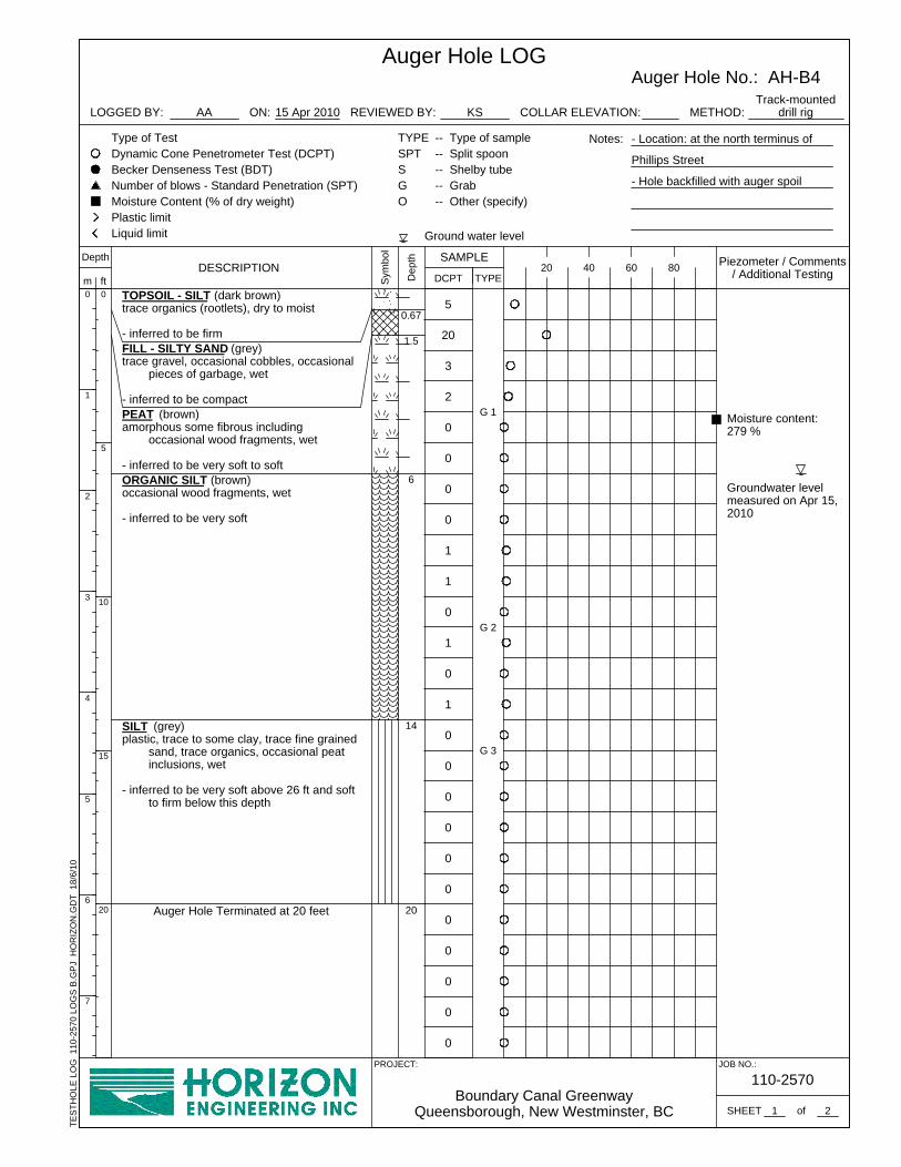
0
0
0
0
0
1
0
1
0
1
1
0
0
0
2
3
20
5
0
TES
THO
LE L
OG
110
-257
0 LO
GS
B.G
PJ
HO
RIZ
ON
.GD
T 1
8/6/
10
G 1
0
0
0
0
0
0
6
20
Groundwater levelmeasured on Apr 15,2010
Moisture content:279 %
Auger Hole Terminated at 20 feet
SILT (grey)plastic, trace to some clay, trace fine grained
sand, trace organics, occasional peatinclusions, wet
- inferred to be very soft above 26 ft and softto firm below this depth
ORGANIC SILT (brown)occasional wood fragments, wet
- inferred to be very soft
PEAT (brown)amorphous some fibrous including
occasional wood fragments, wet
- inferred to be very soft to soft
FILL - SILTY SAND (grey)trace gravel, occasional cobbles, occasional
pieces of garbage, wet
- inferred to be compact
TOPSOIL - SILT (dark brown)trace organics (rootlets), dry to moist
- inferred to be firm
G 3
G 2
1.5
0.67
14
Boundary Canal GreenwayQueensborough, New Westminster, BC
SAMPLE
TYPESPTSGO
Type of TestDynamic Cone Penetrometer Test (DCPT)Becker Denseness Test (BDT)Number of blows - Standard Penetration (SPT)Moisture Content (% of dry weight)Plastic limitLiquid limit
REVIEWED BY: KS
4020
0
1
2
3
4
5
6
7
Sym
bol
110-2570JOB NO.:
Dep
th
Auger Hole No.: AH-B4Auger Hole LOG
Track-mounteddrill rig
PROJECT:
LOGGED BY:
DCPT60
Ground water level
0
5
10
15
20
1
DESCRIPTIONDepth
SHEET
ft
15 Apr 2010
TYPE80
ON:
2
METHOD:
- Location: at the north terminus of
Phillips Street
- Hole backfilled with auger spoil
Notes:
Piezometer / Comments/ Additional Testing
of
-- Type of sample-- Split spoon-- Shelby tube-- Grab-- Other (specify)
m
AA COLLAR ELEVATION:

TYPEDESCRIPTION
ft
15 Apr 2010
SHEET
-- Type of sample-- Split spoon-- Shelby tube-- Grab-- Other (specify)
of
80Depth
3
0
3
6
AA
4
5
4
4
5
5
4
5
3
5
SAMPLE
Ground water level
KS
DCPT
TYPESPTSGO
Type of TestDynamic Cone Penetrometer Test (DCPT)Becker Denseness Test (BDT)Number of blows - Standard Penetration (SPT)Moisture Content (% of dry weight)Plastic limitLiquid limit
m
Auger Hole No.: AH-B4Auger Hole LOG
Track-mounteddrill rig
PROJECT:
LOGGED BY:
60
2
40
- Location: at the north terminus of
Phillips Street
- Hole backfilled with auger spoil
REVIEWED BY:
Piezometer / Comments/ Additional Testing
ON: COLLAR ELEVATION:
TES
THO
LE L
OG
110
-257
0 LO
GS
B.G
PJ
HO
RIZ
ON
.GD
T 1
8/6/
10
Notes:
20
Dep
th
Sym
bol
Boundary Canal GreenwayQueensborough, New Westminster, BC
METHOD:
2
110-2570JOB NO.:
25
30
35
40
45
8
9
10
11
12
13
14
15

4
6
5
9
8
8
7
11
23
22
7
5
23.5
16.5
14
11
8
2
8
TES
THO
LE L
OG
110
-257
0 LO
GS
SD
.GP
J H
OR
IZO
N.G
DT
18/
6/10
G 1
4
7
6
6
5
5
4
3
3
2
3
3
0.67
Groundwater levelmeasured on Apr 19,2010
Moisture content:214%
PEAT (brown)amorphous trace fibrous including wood
fragments, wet
- inferred to be soft to firm
SILT (grey)plastic, some clay, trace fine grained sand,
occasional peat inclusions, wet
- inferred to be soft
SAND (grey)fine to medium grained sand, trace gravel,
wet
- inferred to be loose
ORGANIC SILT (grey mottled brown)trace organics (wood fragments), wet
- inferred to be firm
FILL - SILTY SAND (grey)trace gravel, occasional cobbles, occasional
debris including pieces of plastic andasphalt, moist
- inferred to be loose- more cobbles below 7 ft
FILL - SAND (brownish grey)fine grained sand with some silt, trace to
some gravel, moist
- inferred to be compact
TOPSOIL - SILTY SAND to SANDY SILT (dark brown)
trace organics (rootlets), dry to moist
- inferred to be compact / very stiff
G 3
G 2
METHOD:
TYPESPTSGO
Type of TestDynamic Cone Penetrometer Test (DCPT)Becker Denseness Test (BDT)Number of blows - Standard Penetration (SPT)Moisture Content (% of dry weight)Plastic limitLiquid limit
REVIEWED BY: KS
4020
Dep
th
Sym
bol
SAMPLE
110-2570JOB NO.:
0
1
2
3
4
5
6
7
2Queensborough South Dyke Riverfront Walkway
South Dyke Road, New Westminster, BC
Auger Hole No.: AH-SD1Auger Hole LOG
Truck-mounteddrill rig
PROJECT:
LOGGED BY:
1
DCPT60
Ground water level
Depth
0
5
10
15
20
SHEET
80DESCRIPTIONft TYPE
19 Apr 2010
Piezometer / Comments/ Additional Testing
AA COLLAR ELEVATION:ON:
m
-- Type of sample-- Split spoon-- Shelby tube-- Grab-- Other (specify)
Notes: - Location: south of Thompson
Landing Park
- Hole backfilled with auger spoil and
bentonite chips
of

47
13
51
41
24
23
17
16
17
15
TES
THO
LE L
OG
110
-257
0 LO
GS
SD
.GP
J H
OR
IZO
N.G
DT
18/
6/10
59
TYPE
G 4
80DESCRIPTIONft
19 Apr 2010
15
13
Auger Hole Terminated at 35 feet
SAND (dark grey)fine grained sand, trace to no silt, wet
- inferred to be compact
SILT (grey)some clay, trace fine grained sand, wet
- inferred to be stiff to very stiff
SILT (grey)plastic, some clay, trace fine grained sand,
occasional peat inclusions, wet
- inferred to be stiff (Continued)
28
14
12
11
10
9
33.5
35
SAMPLE
TYPESPTSGO
REVIEWED BY: KS
4020
Dep
th
Sym
bol
SHEET
Type of TestDynamic Cone Penetrometer Test (DCPT)Becker Denseness Test (BDT)Number of blows - Standard Penetration (SPT)Moisture Content (% of dry weight)Plastic limitLiquid limit
2
Auger Hole No.: AH-SD1Auger Hole LOG
Truck-mounteddrill rig
PROJECT:
LOGGED BY:
Ground water level
DCPT60
Queensborough South Dyke Riverfront WalkwaySouth Dyke Road, New Westminster, BC
COLLAR ELEVATION:AA
m
-- Type of sample-- Split spoon-- Shelby tube-- Grab-- Other (specify)
of
Depth
METHOD:
JOB NO.:
25
30
35
40
45
8
9
10
11
12
13
14
15
ON:
110-2570
2
- Location: south of Thompson
Landing Park
- Hole backfilled with auger spoil and
bentonite chips
Notes:
Piezometer / Comments/ Additional Testing

6
9
9
13
31
24
12
11
16
8
4
3
22
16.5
15.5
10
8
3
0.5
8
TES
THO
LE L
OG
110
-257
0 LO
GS
SD
.GP
J H
OR
IZO
N.G
DT
18/
6/10
G 1
5
8
8
7
6
6
5
5
5
5
3
4
Groundwater levelmeasured on Apr 19,2010
SILTY SAND (grey)fine grained sand, some silt to silty, wet
- inferred to be stiff / compact to loose
SILT (grey)plastic, some clay, trace fine grained sand,
occasional fibrous organics or peatinclusions, wet
- inferred to be firm
PEAT (brown)amorphous trace fibrous including wood
fragments, wet
- inferred to be firm
SILT (grey mottled brown)plastic, some clay, trace fine grained sand,
occasional peat inclusions, wet
- inferred to be soft to firm- colour changes to grey below 13.5 ft
SAND (grey)fine to medium grained sand, trace gravel,
moist to wet
- inferred to be loose
SILTY SAND (grey)trace gravel, occasional cobbles, moist
- inferred to be compact to loose- inferred to be fill
SAND (brown)fine grained, some silt, trace to some gravel,
moist
- inferred to be compact- inferred to be fill
TOPSOIL - SILTY SAND to SANDY SILT (dark brown)
trace organics (rootlets), dry to moist
- inferred to be loose / firm
G 4
G 3
G 2
METHOD:
TYPESPTSGO
Type of TestDynamic Cone Penetrometer Test (DCPT)Becker Denseness Test (BDT)Number of blows - Standard Penetration (SPT)Moisture Content (% of dry weight)Plastic limitLiquid limit
REVIEWED BY: KS
4020
Dep
th
Sym
bol
SAMPLE
110-2570JOB NO.:
0
1
2
3
4
5
6
7
2Queensborough South Dyke Riverfront Walkway
South Dyke Road, New Westminster, BC
Auger Hole No.: AH-SD2Auger Hole LOG
Truck-mounteddrill rig
PROJECT:
LOGGED BY:
1
DCPT60
Ground water level
0
5
10
15
20
SHEET
80DESCRIPTIONft
Depth
TYPE
19 Apr 2010
Piezometer / Comments/ Additional Testing
AA COLLAR ELEVATION:ON:
m
-- Type of sample-- Split spoon-- Shelby tube-- Grab-- Other (specify)
Notes: - Location: at Phillips intersection
- Hole backfilled with auger spoil and
bentonite chips
of

57
34
68
43
50
41
32
33
43
29
SHEET
64
G 5
DESCRIPTIONft
19 Apr 2010
46
TYPE
22Auger Hole Terminated at 35 feet
SAND (dark grey)fine grained sand, trace to no silt, wet
- inferred to be dense
SILTY SAND (grey)fine grained sand, some silt to silty, wet
- inferred to be stiff / compact to loose(Continued)
35
43
42
14
14
15
10
11
10
31.5
REVIEWED BY:
SAMPLE
TYPESPTSGO
Type of TestDynamic Cone Penetrometer Test (DCPT)Becker Denseness Test (BDT)Number of blows - Standard Penetration (SPT)Moisture Content (% of dry weight)Plastic limitLiquid limit
KS
4020
Dep
th
Sym
bol
Queensborough South Dyke Riverfront WalkwaySouth Dyke Road, New Westminster, BC
80
2
Auger Hole No.: AH-SD2Auger Hole LOG
Truck-mounteddrill rig
PROJECT:
LOGGED BY:
Ground water level
DCPT60
ON:AA
m
-- Type of sample-- Split spoon-- Shelby tube-- Grab-- Other (specify)
of
TES
THO
LE L
OG
110
-257
0 LO
GS
SD
.GP
J H
OR
IZO
N.G
DT
18/
6/10
Depth
METHOD:
110-2570JOB NO.:
25
30
35
40
45
8
9
10
11
12
13
14
15
COLLAR ELEVATION:
2
- Location: at Phillips intersection
- Hole backfilled with auger spoil and
bentonite chips
Notes:
Piezometer / Comments/ Additional Testing
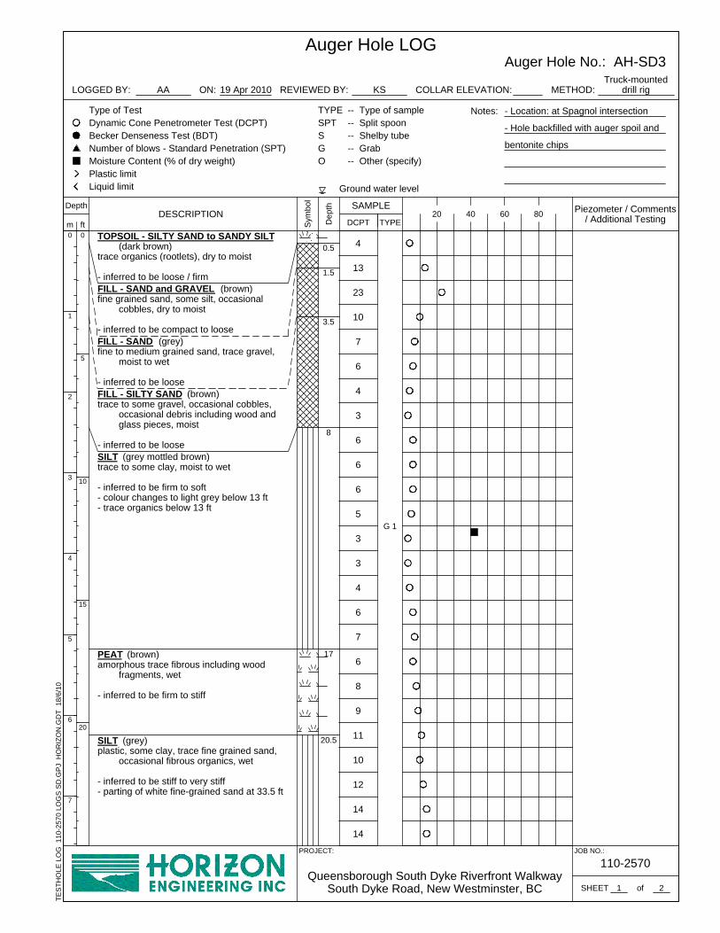
7
7
6
4
3
3
5
6
6
6
3
6
9
10
23
13
4
4
TES
THO
LE L
OG
110
-257
0 LO
GS
SD
.GP
J H
OR
IZO
N.G
DT
18/
6/10
G 1
6
8
14
14
12
10
11
8
20.5SILT (grey)plastic, some clay, trace fine grained sand,
occasional fibrous organics, wet
- inferred to be stiff to very stiff- parting of white fine-grained sand at 33.5 ft
PEAT (brown)amorphous trace fibrous including wood
fragments, wet
- inferred to be firm to stiff
SILT (grey mottled brown)trace to some clay, moist to wet
- inferred to be firm to soft- colour changes to light grey below 13 ft- trace organics below 13 ft
FILL - SILTY SAND (brown)trace to some gravel, occasional cobbles,
occasional debris including wood andglass pieces, moist
- inferred to be loose
FILL - SAND (grey)fine to medium grained sand, trace gravel,
moist to wet
- inferred to be loose
FILL - SAND and GRAVEL (brown)fine grained sand, some silt, occasional
cobbles, dry to moist
- inferred to be compact to loose
TOPSOIL - SILTY SAND to SANDY SILT (dark brown)
trace organics (rootlets), dry to moist
- inferred to be loose / firm
3.5
1.5
0.5
17
Queensborough South Dyke Riverfront WalkwaySouth Dyke Road, New Westminster, BC
TYPESPTSGO
Type of TestDynamic Cone Penetrometer Test (DCPT)Becker Denseness Test (BDT)Number of blows - Standard Penetration (SPT)Moisture Content (% of dry weight)Plastic limitLiquid limit
REVIEWED BY: KS
4020
Sym
bol
110-2570JOB NO.:
0
1
2
3
4
5
6
7
Dep
th
Auger Hole No.: AH-SD3Auger Hole LOG
Truck-mounteddrill rig
PROJECT:
LOGGED BY:
SAMPLE
0
5
10
15
20
DCPT60
Ground water level
1
ft
2
Depth
SHEET
80DESCRIPTION
19 Apr 2010
TYPE
- Location: at Spagnol intersection
- Hole backfilled with auger spoil and
bentonite chips
ON:
Notes:
COLLAR ELEVATION: METHOD:
Piezometer / Comments/ Additional Testing
-- Type of sample-- Split spoon-- Shelby tube-- Grab-- Other (specify)
AA
m
of

TYPEftG 2
19 Apr 2010
Depth
SHEET
80DESCRIPTION
32
Auger Hole Terminated at 35 feet
SILT (grey)plastic, some clay, trace fine grained sand,
occasional fibrous organics, wet
- inferred to be stiff to very stiff- parting of white fine-grained sand at 33.5 ft
(Continued)
G 3
19
27
22
25
21
25
24
26
17
18
18
16
35
20
Ground water level
20SAMPLE
60
TYPESPTSGO
Type of TestDynamic Cone Penetrometer Test (DCPT)Becker Denseness Test (BDT)Number of blows - Standard Penetration (SPT)Moisture Content (% of dry weight)Plastic limitLiquid limit
REVIEWED BY: KS
Auger Hole No.: AH-SD3Auger Hole LOG
Truck-mounteddrill rig
PROJECT:
LOGGED BY:
2
DCPTDep
th
40
- Location: at Spagnol intersection
- Hole backfilled with auger spoil and
bentonite chips
Notes:
Piezometer / Comments/ Additional Testing
ON: COLLAR ELEVATION:AA
m
-- Type of sample-- Split spoon-- Shelby tube-- Grab-- Other (specify)
of
JOB NO.:
Sym
bol
Queensborough South Dyke Riverfront WalkwaySouth Dyke Road, New Westminster, BC
110-2570
TES
THO
LE L
OG
110
-257
0 LO
GS
SD
.GP
J H
OR
IZO
N.G
DT
18/
6/10
25
30
35
40
45
8
9
10
11
12
13
14
15
2
METHOD:

21
38
74
11
7
14
15
10
8
5
4
3
21.67
TES
THO
LE L
OG
110
-257
0 LO
GS
SD
.GP
J H
OR
IZO
N.G
DT
18/
6/10
G 1
13
14
5
8
7
3
1
0
0
4
10
10
SILT (grey mottled brown)plastic, some clay, trace fine grained sand,
occasional peat inclusions, wet
- inferred to be firm to very soft- colour changes to grey below 13.5 ft
(interbedded sand layers)
0.67
Auger Hole Terminated at 15 feet
SAND (grey)fine to medium grained, trace gravel, moist to
wet
- inferred to be loose
SILTY SAND / SANDY SILT (brown)trace to some gravel, occasional cobbles, dry
to moist
- inferred to be compact / stiff
SAND (dark grey)fine to medium grained, trace to some silt,
trace organics, dry to moist
- inferred to be compact- inferred to be fill
SAND (grey)fine to medium grained, trace gravel, trace
debris (wood), dry to moist
- inferred to be compact- inferred to be fill
FILL - GRAVELLY SAND (grey)well graded sand with some gravel to
gravelly, dry to moist
- inferred to be dense
ASPHALT (black)
FILL - SAND (grey)fine to medium grained, trace gravel, dry to
moist
- inferred to be compact
TOPSOIL - SILTY SAND to SANDY SILT (dark brown)
trace organics (rootlets), dry to moist
- inferred to be loose / firm
G 3
G 2Groundwater levelmeasured on Apr 15,2010
Queensborough South Dyke Riverfront WalkwaySouth Dyke Road, New Westminster, BC
SAMPLE
TYPESPTSGO
Type of TestDynamic Cone Penetrometer Test (DCPT)Becker Denseness Test (BDT)Number of blows - Standard Penetration (SPT)Moisture Content (% of dry weight)Plastic limitLiquid limit
REVIEWED BY: KS
4020
0
1
2
3
4
5
6
7
Sym
bol
JOB NO.:
0
5
10
15
20
Dep
th
Auger Hole No.: AH-SD4Auger Hole LOG
Track-mounteddrill rig
PROJECT:
LOGGED BY:
DCPT60
Ground water level
1
80
110-2570
Depth
SHEET
DESCRIPTIONft
15 Apr 2010
TYPE
COLLAR ELEVATION:
1
METHOD:
- Location: at Gifford intersection
- Hole backfilled with auger spoil
Notes:
Piezometer / Comments/ Additional Testing
ON:
of
AA
m
-- Type of sample-- Split spoon-- Shelby tube-- Grab-- Other (specify)

5
10
8
6
TES
THO
LE L
OG
110
-257
0 LO
GS
SD
.GP
J H
OR
IZO
N.G
DT
18/
6/10
3
5
5
4
4
4
4
4
5
4
G 1
ft
15 Apr 2010
TYPE
18
5
Groundwater levelmeasured on Apr 15,2010
Auger Hole Terminated at 15 feet
SILT (brown)trace fine grained sand, trace clay, wet
- inferred to be firm to stiff
SAND (dark grey)fine to medium grained, trace gravel, dry to
moist
- inferred to be loose- inferred to be fill
FILL - SILTY SAND (brown)fine to medium grained sand, trace to some
gravel, dry to moist
- inferred to be compact to loose- inferred to be fill
G 3
G 2
80
11
15
7
4.5
6
REVIEWED BY:
SHEET
SAMPLE
TYPESPTSGO
Type of TestDynamic Cone Penetrometer Test (DCPT)Becker Denseness Test (BDT)Number of blows - Standard Penetration (SPT)Moisture Content (% of dry weight)Plastic limitLiquid limit Ground water level
KS
4020
Dep
th
Sym
bol
Queensborough South Dyke Riverfront WalkwaySouth Dyke Road, New Westminster, BC
DESCRIPTION
1
Auger Hole No.: AH-SD5Auger Hole LOG
Track-mounteddrill rig
PROJECT:
LOGGED BY:
DCPT60
COLLAR ELEVATION:
m
-- Type of sample-- Split spoon-- Shelby tube-- Grab-- Other (specify)
of
ON:
Depth
0
5
10
15
20
0
1
2
3
4
5
6
7
1
METHOD:AA
110-2570
- Location: at Wood intersection
- Hole backfilled with auger spoil
Notes:
Piezometer / Comments/ Additional Testing
JOB NO.:

0
6
2
1
1
1
1
1
1
1
0
4
0
0
0
1
1
3
5
1
TES
THO
LE L
OG
110
-257
0 LO
GS
S.G
PJ
HO
RIZ
ON
.GD
T 2
1/6/
10
G 1
5
3
6
15
Moisture content:346%
Groundwater levelmeasured on Apr 15,2010
Auger Hole Terminated at 15 feet
SILT (grey)plastic, trace to some clay, trace fine grained
sand, occasional peat inclusions, wet
- inferred to be very soft
ORGANIC SILT (greyish brown)occasional wood fragments, moist to wet
- inferred to be very soft
PEAT (brown)amorphous and fibrous (including occasional
wood fragments), wet
- inferred to be very soft
SAND (brown)fine to medium grained, trace to some silt,
moist to wet
- inferred to be very loose to loose- inferred to be fill
TOPSOIL - SILT (dark brown)trace organics (rootlets), dry to moist
- inferred to be firm
9
6
2
1
Dep
th SAMPLE
TYPESPTSGO
Type of TestDynamic Cone Penetrometer Test (DCPT)Becker Denseness Test (BDT)Number of blows - Standard Penetration (SPT)Moisture Content (% of dry weight)Plastic limitLiquid limit
REVIEWED BY: KS
20
Sym
bol
Stanley Street TrailQueensborough, New Westminster, BC
JOB NO.:
40
Auger Hole No.: AH-S1Auger Hole LOG
Track-mounteddrill rig
PROJECT:
LOGGED BY:
DCPT60
Ground water level
1SHEET
0
5
10
15
20
110-2570
Depth80DESCRIPTION
ft
15 Apr 2010
TYPE
- Location: at the north terminus of
trail
- Hole backfilled with auger spoil
Notes:
Piezometer / Comments/ Additional Testing
METHOD:
1
0
1
2
3
4
5
6
7
ON: COLLAR ELEVATION:AA
m
-- Type of sample-- Split spoon-- Shelby tube-- Grab-- Other (specify)
of

1
4
2
3
2
1
2
1
1
1
1
7
0
0
0
0
2
3
5
5
0
TES
THO
LE L
OG
110
-257
0 LO
GS
S.G
PJ
HO
RIZ
ON
.GD
T 1
8/6/
10
G 1
6
5
Moisture content:161%
Auger Hole Terminated at 15 feet
SILT (grey)plastic, trace to some clay, trace fine grained
sand, trace organics, occasional peatinclusions, wet
- inferred to be very soft
ORGANIC SILT (greyish brown)occasional wood fragments, moist to wet
- inferred to be very soft
PEAT (brown)trace organics (wood fragments), moist to
wet
- inferred to be very soft
FILL - SAND (brown)fine to medium grained, trace to some silt,
moist to wet
- inferred to be very loose to loose- inferred to be fill
TOPSOIL - SILT (dark brown)trace organics (rootlets), dry to moist
- inferred to be firm
15
13.5
6
3
1
Dep
th SAMPLE
TYPESPTSGO
Type of TestDynamic Cone Penetrometer Test (DCPT)Becker Denseness Test (BDT)Number of blows - Standard Penetration (SPT)Moisture Content (% of dry weight)Plastic limitLiquid limit
REVIEWED BY: KS
20
Sym
bol
Stanley Street TrailQueensborough, New Westminster, BC
JOB NO.:
40
Auger Hole No.: AH-S2Auger Hole LOG
Track-mounteddrill rig
PROJECT:
LOGGED BY:
DCPT60
Ground water level
1
0
5
10
15
20
110-2570
Depth
SHEET
80DESCRIPTIONft
15 Apr 2010
TYPE
- Location: at the middle of trail
- Hole backfilled with auger spoil
Notes:
Piezometer / Comments/ Additional Testing
METHOD:
1
0
1
2
3
4
5
6
7
ON: COLLAR ELEVATION:AA
m
-- Type of sample-- Split spoon-- Shelby tube-- Grab-- Other (specify)
of

3
TES
THO
LE L
OG
110
-257
0 LO
GS
S.G
PJ
HO
RIZ
ON
.GD
T 1
8/6/
10
4
4
4
4
4
2
2
1
0
0
0
1
4
6
8
3
ft
G 1
15 Apr 2010
TYPE
Moisture content:213%
Groundwater levelmeasured on Apr 15,2010
4
Auger Hole Terminated at 15 feet
ORGANIC SILT (greyish brown)occasional wood fragments, moist to wet
- inferred to be soft
PEAT (brown)amorphous and fibrous (including occasional
wood fragments), moist to wet
- inferred to be very soft to soft
FILL - SILT (grey mottled brown)trace fine grained sand, moist
- inferred to be firm above 3.5 ft and very softbelow this depth
- colour changes to grey below 4.5 ft- inferred to be fill
TOPSOIL - SILT (dark brown)trace organics (rootlets), dry to moist
- inferred to be soft to firm
G 2
DESCRIPTION
15
11
7
1
KS
SAMPLE
TYPESPTSGO
Type of TestDynamic Cone Penetrometer Test (DCPT)Becker Denseness Test (BDT)Number of blows - Standard Penetration (SPT)Moisture Content (% of dry weight)Plastic limitLiquid limit
REVIEWED BY:
4020
Dep
th
Sym
bol
Stanley Street TrailQueensborough, New Westminster, BC
Auger Hole No.: AH-S3Auger Hole LOG
Track-mounteddrill rig
PROJECT:
LOGGED BY:
1
Ground water level
DCPT60
-- Type of sample-- Split spoon-- Shelby tube-- Grab-- Other (specify)
of
110-2570
AA
Depth
SHEET
80
0
1
2
3
4
5
6
7
1
METHOD:
m0
5
10
15
20
- Location: at the south terminus of
trail
- Hole backfilled with auger spoil
JOB NO.:
Notes:
Piezometer / Comments/ Additional Testing
ON: COLLAR ELEVATION:

City of New Westminster c/o Durante Kreuk Our File: 110-2570Proposed Queensborough Greenway June 18, 2010Geotechnical Investigation Report Appendices
APPENDIX C
CPT Interpretation and Analyses Results

0
1
2
3
4
5
6
7
8
9
0 4 8 12 16 20D
epth
(m
)Norm. Tip Res. qt (MPa)
0
1
2
3
4
5
6
7
8
9
0 50 100 150Fs (KPa)
0
1
2
3
4
5
6
7
8
9
0 5 10 15 20Rf (Fs/Qt) % Organic
CohesiveNon-cohesive
0
1
2
3
4
5
6
7
8
9
-100 0 100 200 300 400Pore Pressure (KPa)
mpl
e vi
sual
izat
ion
of s
oil t
ype
Location : South Dyke RoadCone Type: 10305 10 Ton
Borehole: CPT-SD2 Calc. By: AA Date : CA-B1Drill Date : April 19 2010 Chk. By: KS Jun-10 110-2570
Queensborough Greenways (South Dyke Road)
Data
pro
cess
ed b
y N
ovo
CPT v
1.5
.0.2
7
CPT Interpretation and Simplified Soil BehaviourFigure No.:
File :
0
1
2
3
4
5
6
7
8
9
10
11
12
13
14
15
0 4 8 12 16 20D
epth
(m
)Norm. Tip Res. qt (MPa)
0
1
2
3
4
5
6
7
8
9
10
11
12
13
14
15
0 50 100 150Fs (KPa)
0
1
2
3
4
5
6
7
8
9
10
11
12
13
14
15
0 5 10 15 20Rf (Fs/Qt) % Organic
CohesiveNon-cohesive
0
1
2
3
4
5
6
7
8
9
10
11
12
13
14
15
-100 0 100 200 300 400Pore Pressure (KPa)
Sim
ple
visu
aliz
atio
n of
soi
l typ
e

Location : 110-2570Cone Type: 10305 10 Ton
Borehole: CPT-SD2 Calc. By: AA Date : CA-SBT1Drill Date : April 19 2010 Chk. By: KS May-10 110-2570 D
ata
pro
cess
ed b
y N
ovo
CPT v
1.4
.0.2
7
Queensborough Greenways (South Dyke Road)Soil Behaviour Type Charts
Figure No.:File :
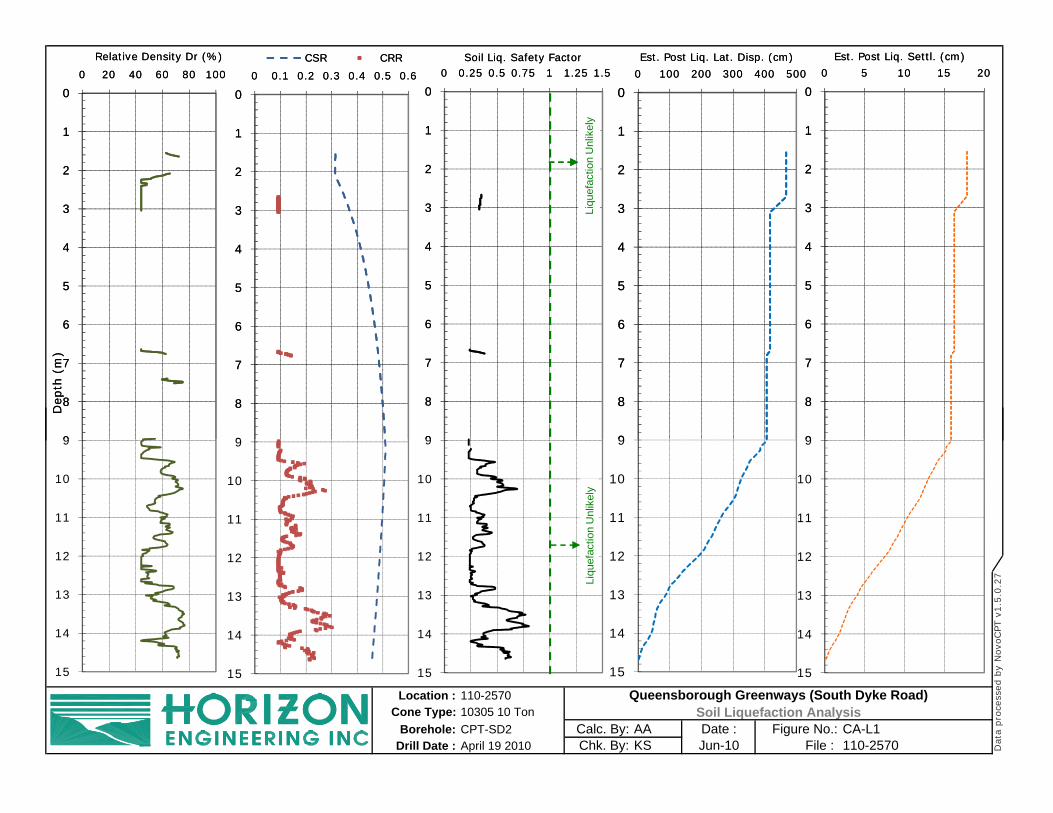
0
1
2
3
4
5
6
7
8
9
0 0.25 0.5 0.75 1 1.25 1.5Soil Liq. Safety Factor
0
1
2
3
4
5
6
7
8
9
0 100 200 300 400 500
Est. Post Liq. Lat. Disp. (cm)
Liqu
efac
tion
Unl
ikel
y
0
1
2
3
4
5
6
7
8
9
0 5 10 15 20
Est. Post Liq. Settl. (cm)
0
1
2
3
4
5
6
7
8
9
0 20 40 60 80 100
Dep
th (
m)
Relative Density Dr (%)
0
1
2
3
4
5
6
7
8
9
0 0.1 0.2 0.3 0.4 0.5 0.6
CSR CRR
Location : 110-2570Cone Type: 10305 10 Ton
Borehole: CPT-SD2 Calc. By: AA Date : CA-L1Drill Date : April 19 2010 Chk. By: KS Jun-10 110-2570
Queensborough Greenways (South Dyke Road)
Data
pro
cess
ed b
y N
ovo
CPT v
1.5
.0.2
7
Soil Liquefaction AnalysisFigure No.:
File :
0
1
2
3
4
5
6
7
8
9
10
11
12
13
14
15
0 0.25 0.5 0.75 1 1.25 1.5Soil Liq. Safety Factor
0
1
2
3
4
5
6
7
8
9
10
11
12
13
14
15
0 100 200 300 400 500
Est. Post Liq. Lat. Disp. (cm)
Liqu
efac
tion
Unl
ikel
y
0
1
2
3
4
5
6
7
8
9
10
11
12
13
14
15
0 5 10 15 20
Est. Post Liq. Settl. (cm)
Liqu
efac
tion
Unl
ikel
y
0
1
2
3
4
5
6
7
8
9
10
11
12
13
14
15
0 20 40 60 80 100
Dep
th (
m)
Relative Density Dr (%)
0
1
2
3
4
5
6
7
8
9
10
11
12
13
14
15
0 0.1 0.2 0.3 0.4 0.5 0.6
CSR CRR
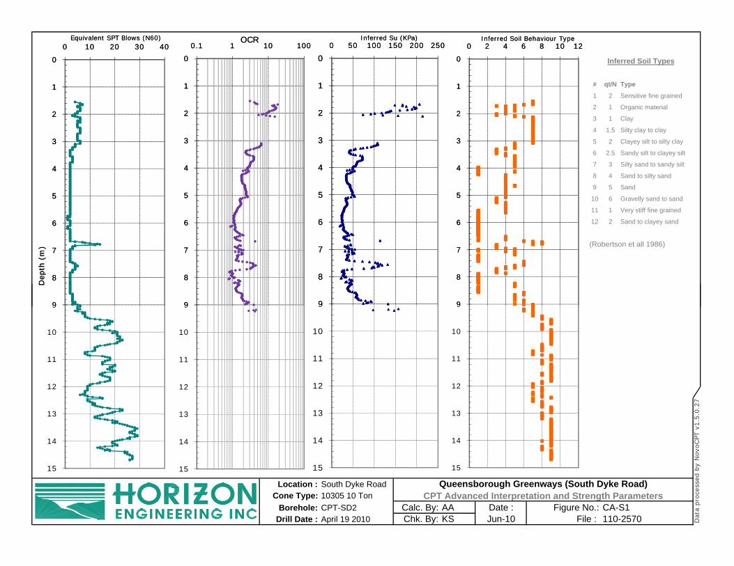
# qt/N Type
1 2 Sensitive fine grained
2 1 Organic material
3 1 Clay
4 1.5 Silty clay to clay
5 2 Clayey silt to silty clay
6 2.5 Sandy silt to clayey silt
7 3 Silty sand to sandy silt
8 4 Sand to silty sand
9 5 Sand
10 6 Gravelly sand to sand
11 1 Very stiff fine grained
12 2 Sand to clayey sand
(Robertson et all 1986)
Inferred Soil Types0
1
2
3
4
5
6
7
8
9
0 10 20 30 40D
epth
(m
)Equivalent SPT Blows (N60)
0
1
2
3
4
5
6
7
8
9
0 50 100 150 200 250Inferred Su (KPa)
0
1
2
3
4
5
6
7
8
9
0 2 4 6 8 10 12Inferred Soil Behaviour Type
0
1
2
3
4
5
6
7
8
9
0.1 1 10 100OCR
Location : South Dyke RoadCone Type: 10305 10 Ton
Borehole: CPT-SD2 Calc. By: AA Date : CA-S1Drill Date : April 19 2010 Chk. By: KS Jun-10 110-2570
Queensborough Greenways (South Dyke Road)
Data
pro
cess
ed b
y N
ovo
CPT v
1.5
.0.2
7
CPT Advanced Interpretation and Strength ParametersFigure No.:
File :
0
1
2
3
4
5
6
7
8
9
10
11
12
13
14
15
0 10 20 30 40D
epth
(m
)Equivalent SPT Blows (N60)
0
1
2
3
4
5
6
7
8
9
10
11
12
13
14
15
0 50 100 150 200 250Inferred Su (KPa)
0
1
2
3
4
5
6
7
8
9
10
11
12
13
14
15
0 2 4 6 8 10 12Inferred Soil Behaviour Type
0
1
2
3
4
5
6
7
8
9
10
11
12
13
14
15
0.1 1 10 100OCR

City of New Westminster c/o Durante Kreuk Our File: 110-2570Proposed Queensborough Greenway June 18, 2010Geotechnical Investigation Report Appendices
APPENDIX D
Pile Analysis Results

0
1
2
3
4
5
6
7
0 100 200 300
Pile Allowable Axial Capacity (kN)
Diameter=8"
Diameter=10"
0
1
2
3
4
5
6
7
0 100 200 300 400
Dep
th (
m)
Ultimate Capacity (kN) for 8" diameter timber pile
Friction Capacity
End Capacity
0
1
2
3
4
5
6
7
0 100 200 300 400
Ultimate Capacity (kN) for 10" diameter timber pile
Friction Capacity
End Capacity
Note: Zero depth in these plots corresponds to river bed at toe of dyke.Location : 110-2570
Cone Type: 10305 10 TonBorehole: CPT-SD2 Calc. By: AA Date : CA-P1
Drill Date : April 19 2010 Chk. By: KS Jun-10 110-2570 Data
pro
cess
ed b
y N
ovo
CPT
v1.5
.0.2
7
Queensborough Greenways (South Dyke Road)Allowable Bearing Capacity of Timber Piles
Figure No.:File :
0
1
2
3
4
5
6
7
8
9
10
11
12
13
0 100 200 300
Pile Allowable Axial Capacity (kN)
Diameter=8"
Diameter=10"
0
1
2
3
4
5
6
7
8
9
10
11
12
13
0 100 200 300 400
Dep
th (
m)
Ultimate Capacity (kN) for 8" diameter timber pile
Friction Capacity
End Capacity
0
1
2
3
4
5
6
7
8
9
10
11
12
13
0 100 200 300 400
Ultimate Capacity (kN) for 10" diameter timber pile
Friction Capacity
End Capacity

0
1
2
3
4
5
6
7
0 100 200 300 400 500
Pile Allowable Axial Capacity (kN)
Diameter=16"
Diameter=18"
0
1
2
3
4
5
6
7
0 200 400 600 800
Dep
th (
m)
Ultimate Capacity (kN) for 16" diameter steel pipe pile
Friction Capacity
End Capacity
0
1
2
3
4
5
6
7
0 200 400 600 800 1000
Ultimate Capacity (kN) for 18" diameter steel pipe pile
Friction Capacity
End Capacity
Note: Zero depth in these plots corresponds to river bed at toe of dyke.Location : 110-2570
Cone Type: 10305 10 TonBorehole: CPT-SD2 Calc. By: AA Date : CA-P2
Drill Date : April 19 2010 Chk. By: KS Jun-10 110-2570 Data
pro
cess
ed b
y N
ovo
CPT v
1.5
.0.2
7
Queensborough Greenways (South Dyke Road)Allowable Bearing Capacity of Steel Pipe Piles
Figure No.:File :
0
1
2
3
4
5
6
7
8
9
10
11
12
13
0 100 200 300 400 500
Pile Allowable Axial Capacity (kN)
Diameter=16"
Diameter=18"
0
1
2
3
4
5
6
7
8
9
10
11
12
13
0 200 400 600 800
Dep
th (
m)
Ultimate Capacity (kN) for 16" diameter steel pipe pile
Friction Capacity
End Capacity
0
1
2
3
4
5
6
7
8
9
10
11
12
13
0 200 400 600 800 1000
Ultimate Capacity (kN) for 18" diameter steel pipe pile
Friction Capacity
End Capacity

P=115 kN
00.5
11.5
22.5
33.5
44.5
55.5
66.5
77.5
8
0 50 100 150
Dep
th (m
)
Lateral Deflection Y (mm)‐200 ‐100 0 100 200
Shear Force V (kN)0 150 300 450 600
Bending Moment (kN.m)
H=155 kN
~ 1.55 m
Notes:* This calculation is performed for driven steel pipe piles, with pinned head connection to the structure, for pile sizes provided in Section 7.2.2 of this report
* Allowable structural capacities to be verified by structural engineer
* If any of the above assumptions change, results should be reviewed by Horizon Engineering.
Calc: AAChk: TISouth Dyke Riverfront Greenway,
Queensborough, New Westminster, BC Pile Lateral Deflection Analysis
110‐2570June 2010
Figure PA‐C1
00.5
11.5
22.5
33.5
44.5
55.5
66.5
77.5
88.5
99.510
10.511
11.512
12.513
0 50 100 150
Dep
th (m
)
Lateral Deflection Y (mm)‐200 ‐100 0 100 200
Shear Force V (kN)0 150 300 450 600
Bending Moment (kN.m)
H=155 kN
~ 1.55 m