city and borough of juneau conceptual design report … and borough of juneau conceptual design...
TRANSCRIPT
City and Borough of Juneau Conceptual Design Report Juneau International Airport Snow Removal Equipment Facility
- i -
Table of Contents Volume 1 – Conceptual Design Report
Executive Summary
1. Scope of Work
2 History and Need
Origin and Need Condition of Existing Facilities
Operations Existing Situation Future Projections
Safety and Efficiency Staff Equipment Materials Access and Circulation Size of Site
Funding the Need Constructing a Replacement SREF
Site Facilities
Substructure: Shell Interiors Services Equipment and Furnishings Other Building Construction Special Construction Site Preparation Site Improvements Site Plumbing Utilities
3. Conclusion
APPENDICES I. FAA Terminal Area Forecast (TAF) II. Conceptual Site Plan and Floor Plan III. Programming Matrix IV. Determination of Approved Equipment and Updated Paved Areas V. DRAFT CIP Project Sheet 3/5/2004 VI. Mechanical Narrative and Spreadsheet VII. Electrical Narrative, Sketch, and Spreadsheet VIII. Project Documentation
City and Borough of Juneau Conceptual Design Report Juneau International Airport Snow Removal Equipment Facility
- 1 -
EXECUTIVE SUMMARY
Juneau International Airport (JNU) is planning to expand fixed wing and helicopter development areas. As a consequence, the airport is undergoing an environmental process that includes an Environmental Impact Statement (EIS). The airport is also planning to replace its current aging Snow Removal Equipment Facility (SREF) to assure viable, year-round air passenger transit and cargo operations serving regional and international customers reliably. The purpose of this report is to demonstrate a reasonable development scenario for a new SREF, including area of land impacted by a consolidated facility including equipment and materials storage, support areas (shops and administrative areas), vehicle circulation, outside storage, and vehicle fueling areas for a complete and functioning facility located somewhere on the airfield. The location will be determined through the EIS process.
The existing warm storage and maintenance facilities date from the 1950s and no longer serve the needs of staff or equipment currently in use. Documentation of the need spans the last decade and is objectively seen as critical in several regards. First, the sand shed located on the opposite side of the terminal and is in such a state of disrepair it should be condemned. Secondly, as each year passes fewer and fewer pieces of equipment actually fit into the current maintenance and storage bays. This is due to an industry-wide shift toward larger and more powerful equipment. The current shops were not designed to accommodate this larger equipment and renovating existing buildings from that era does not make economic sense as has been illustrated in earlier reports. Thirdly, the existing SREF cannot house or protect the equipment from the elements in this maritime community.
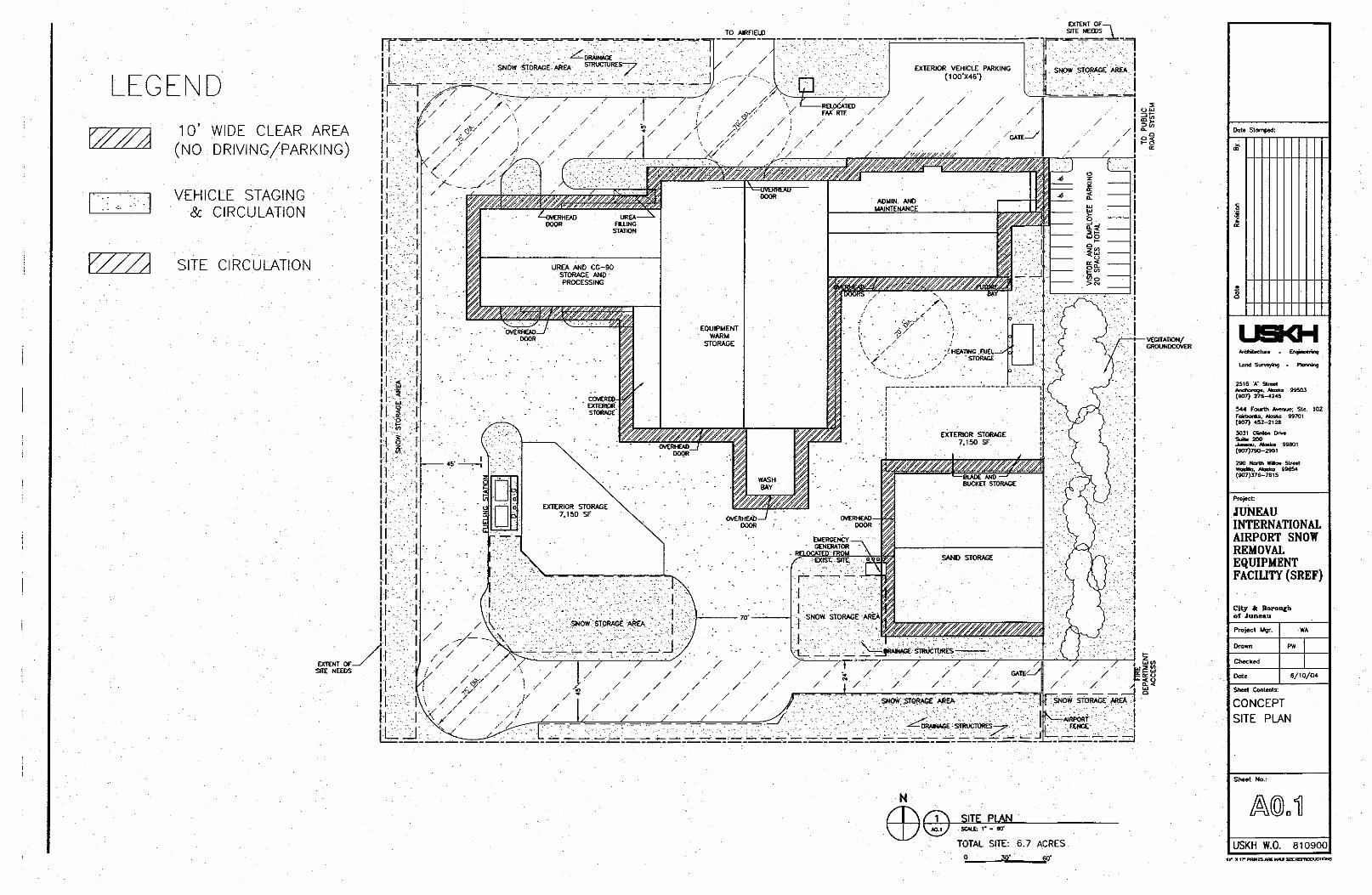
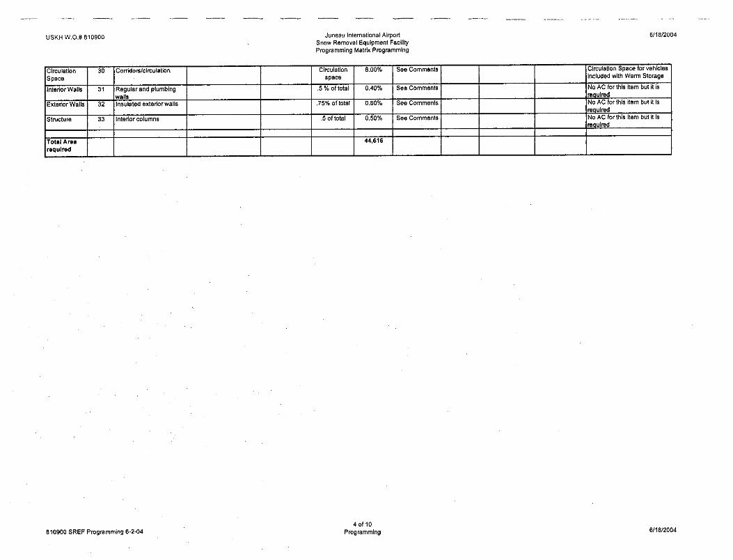
The current EIS is being prepared to address other development at the airport. Part of the EIS addresses the likely size of a replacement SREF, as justified through FAA Advisory Circulars (ACs) and actual conditions on the ground in Juneau. Although several locations for a new facility are being evaluated within the EIS, the footprint or impacted area considered here involves a theoretical site of approximately 6.7 acres, including shop and equipment storage areas totaling approximately 44,616 square feet (sf). The building sizes were derived from a review and analysis of the airports’ equipment inventory, discussions with staff about current and anticipated operations, review of FAA-funded equipment, an use of FAA AC’s related to facility design. The proposed footprint is realistic and supportable judged by AC criteria, as the field maintenance group attempts to consolidate their multi-site assets, bringing them together to create a more efficient and effective operational unit.
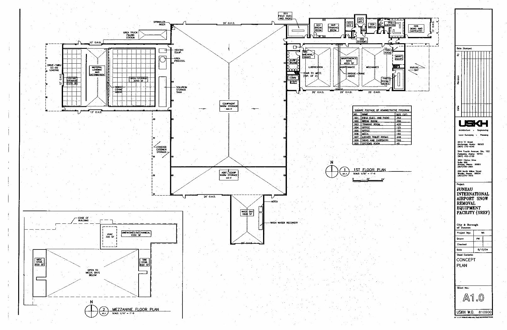
In order to arrive at an area of impact, the consultants conducted extensive interviews and site visits to understand the staffs’ operations and environment, physical assets, and airport layout. A full-day work session was held with airport staff to carefully evaluate conclusions from interviews and site visits prior to working through all the issues affecting a new SREF. The results are a concept site layout suitable for a number of locations at JNU, an area of impact (in acres and sf), floor plans, and a massing study of a facility meeting the needs of JNU.
City and Borough of Juneau Conceptual Design Report Juneau International Airport Snow Removal Equipment Facility
- 2 -
1. SCOPE OF WORK
The components of the project include Space Programming and Research, Conceptual Building Design, Generic Site Design, and a Project Funding Plan.
Space Programming and Research deliverables and tasks include:
• Site visit and programming workshop
• Contact with FAA
• Interviews with JNU personnel
• Develop Spatial Program of inter-relationships
• Present equipment inventory (with 5-year expected acquisitions)
• Equipment Maneuvering Criteria
• Final Space Program with total square footage for building
Conceptual Design deliverables include:
• Theoretical site plan with building(s), adjacent operational requirements, parking, vegetation, potential access points, equipment circulation patterns, and will address FAA and City and Borough of Juneau (CBJ) development standards.
• Floor plan(s) showing equipment and internal circulation patterns, conceptual urea storage and processing layout, and building occupancy areas.
• One or two simple drawings (elevation, section or axonometric) to describe the building's volume and form.
• Narratives discussing building materials and structural, mechanical and electrical systems.
Funding Plan deliverables include (Volume II not included with this submittal)
• Airport SREF Matrix (based on other airport historical research)
• Record of correspondence, meeting, and conversations with the FAA
City and Borough of Juneau Conceptual Design Report Juneau International Airport Snow Removal Equipment Facility
- 3 -
2 HISTORY AND NEED
ORIGIN AND NEED
The origins of this project (to replace and consolidate existing SREF facilities) began more than ten years ago with the realization that current facilities were inadequate to serve JNU’s needs, and have been well documented in a series of previous investigations and reports. Despite the periodic maintenance at JNU, all buildings have a finite life span. Generally, this is 50 years. Some are able to adapt to new requirements but if they cannot, become obsolete. The current facilities at JNU have not kept pace with airfield development or equipment changes in terms of size or features, and the following evidence reinforces managements’ desire to construct new facilities.
Condition of Existing Facilities
The condition of the existing SREF is reasonable given its age of over 40 years. Maintenance has been regular and thorough, and limited life/safety code upgrades have been performed. However, ventilation standards, fire protection of stored petroleum (lubrication) products, and safe access in and around equipment parked inside are unable to be addressed sufficiently in the existing facility because it is structurally impractical. The building is also too small and cannot accommodate some of the newer vehicles, as it was simply not designed to maintain today’s larger, more powerful equipment. For example, equipment doors are not wide enough to allow current 24’ wide snow removal blades inside a building.
Earlier evaluations of the need for a new SREF documented problems with responsiveness when vehicles are iced-over, would not start, or had corrosion problems due to prolonged contact with high-salinity precipitation. However, documentation of warm storage limitations, maintenance shop adequacy, sand storage building occupancy concerns, and deicer inefficiencies were not fully appreciated at the time they were written, and have since become more pressing.
FAA ACs provide planning guidance for airports. In utilizing the numerous ACs relevant to this project, Juneau’s special geographic and climatic location issues must also be considered. The AC’s contain no special language for unique environments such a Juneau’s. That said, establishing the airports’ rating criteria consistent with Order 5100.39B is necessary if FAA funds are to be used for construction of new facilities. The governing document lists the formula on which the FAA, in part, makes funding decisions. Apart from quantitative point values the rating system derives from airport operations, snow clearance times, pavement areas, and equipment makeup, qualitative factors (such as facility conditions) are also to be considered. These are documented below.
• Determination of amount and type of snow removal equipment JNU is approved for; from which the size of the SREF is, in part, derived from. JNU submits annual reports to verify its equipment numbers and obtained reviews from FAA. The methodology included using FAA AC 150/5200-30A and AC 150/5220-20 documents to determine approved equipment.
• The results included findings of snow quantities and clearance times, based on the number of JNU’s annual operations on pavement areas.
o Annual Operations: 40,000 + (this number is difficult to verify based purely on Air Carrier Operations. However, given Juneau’s isolated nature, air taxi operations are
City and Borough of Juneau Conceptual Design Report Juneau International Airport Snow Removal Equipment Facility
- 4 -
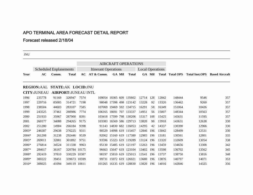
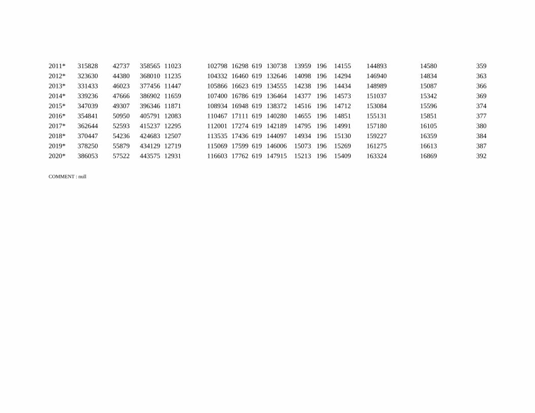
combined due to their critical transportation and high economic importance to the area). Reviewing an on-line version of FAA’s Terminal Area Forecast (TAF), the recorded 2002 annual operations equal a combined 101,223 air carrier, air taxi/commuter, and military operations. The trend over the previous two years for the air carriers indicates a 12% increase in operations while the air taxi/commuter operations actually declined. Reference Appendix I.
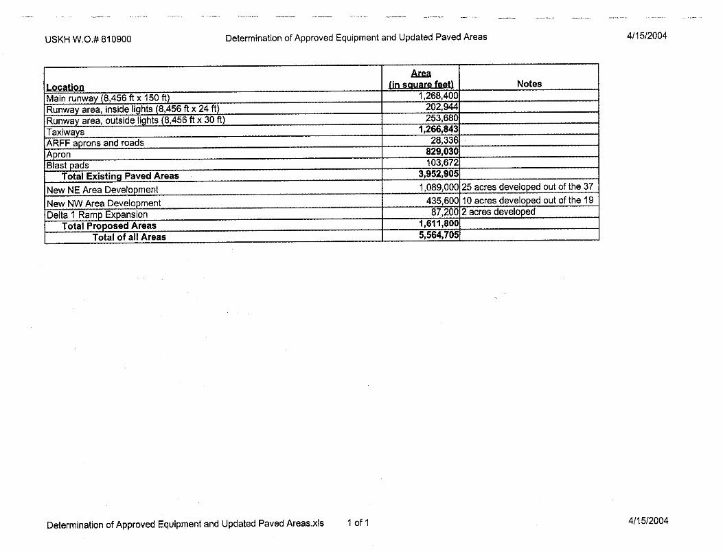
o Area (in sf) of Priority One Surfaces: 4,040,105 sf, as reported in Appendix IV. This includes approximately 87,200 sf of new paving in place for Delta 1 Ramp Expansion listed as “proposed”. Two other areas (the NE and NW Development Areas) are scheduled to be paved as they are developed in the near future. Priority One surfaces receive the highest level of maintenance and snow removal attention because they are required in order for the airfield to remain open.
o Supplementary information includes AC 150/5220-18, which defines facility components and their sizes, and establishes guidelines for determining overall facility size. The AC defines types of spaces including equipment storage, materials storage, and support areas. The key to arriving at an FAA-supportable facility size is determining the equipment type and quantity. From that number all other spaces can be roughly determined.
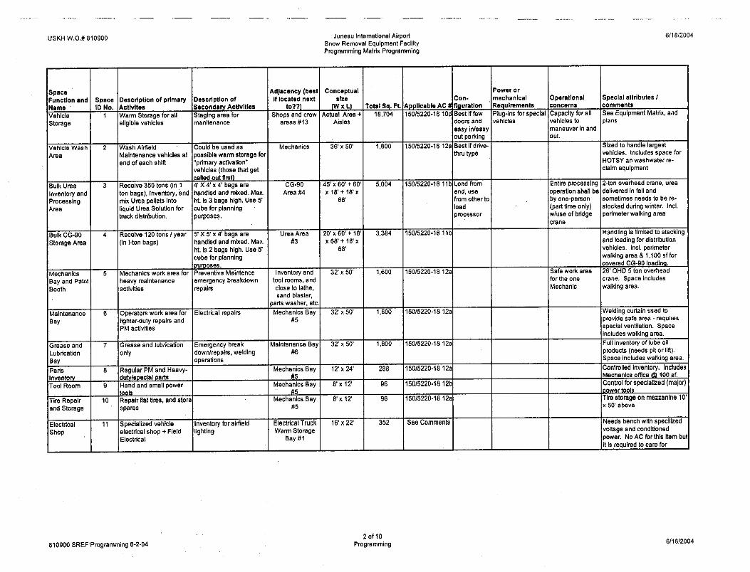
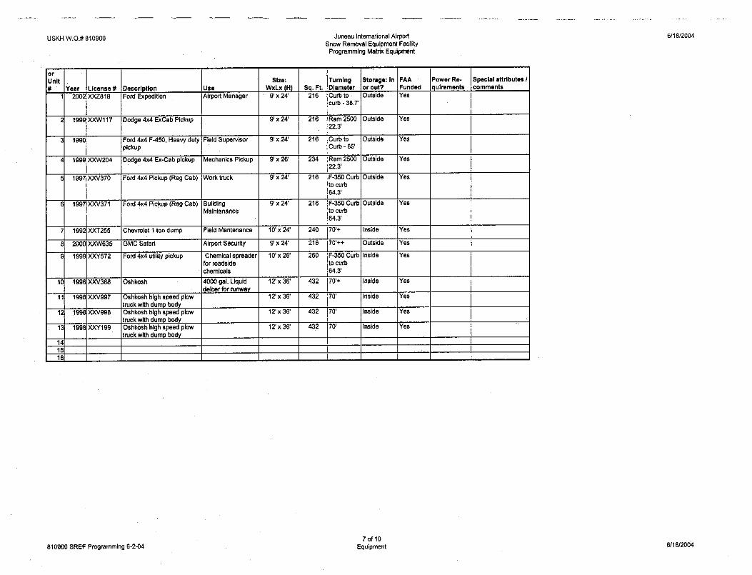
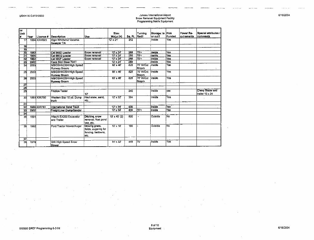
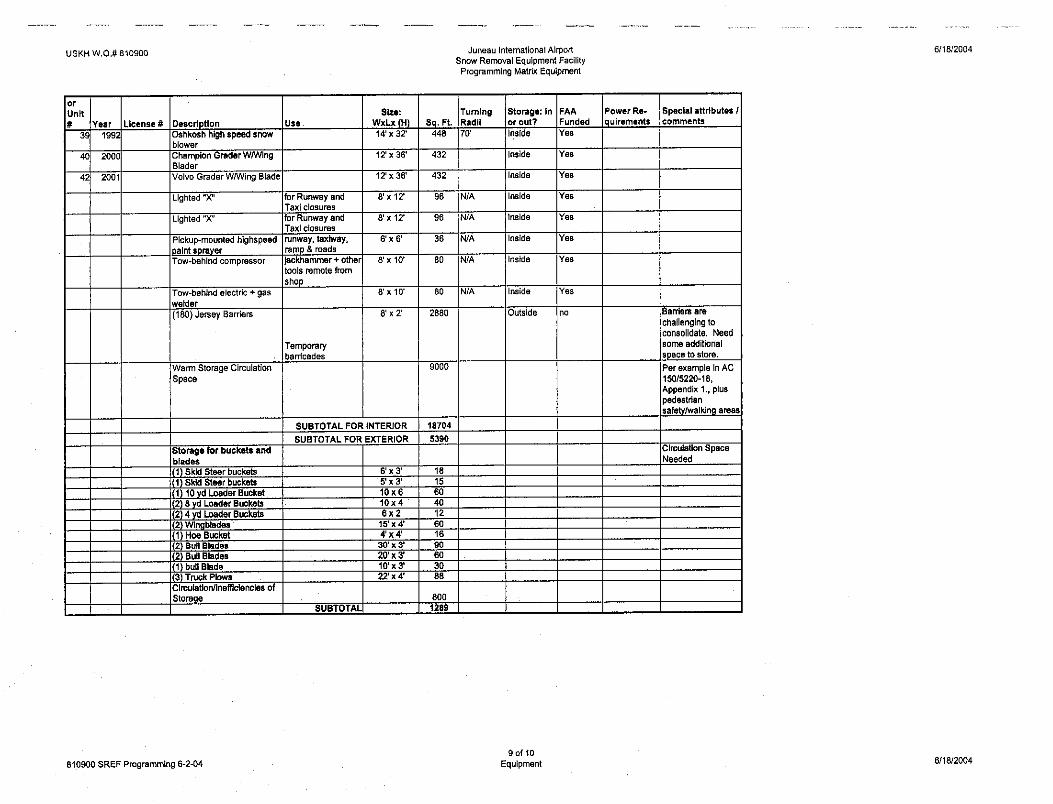
Equipment Storage: This space is for the storage of snow removal equipment. The equipment currently authorized, in use, and projected for replacement within 5 years includes snowblowers, snowplows, sweepers, spreaders, loaders and scrapers. These are all eligible for covered and heated storage. JNU also has equipment that is not eligible for FAA-funded indoor storage, such as the directors and other staff vehicles. A comprehensive list of all equipment is included in Appendix III.
Materials Storage: Currently, all materials needed to properly maintain primary surfaces are located somewhat opportunistically in decentralized locations around the airport, and even off immediate airport grounds: these were never planned comprehensively, as a result they are inefficient to reach and service, and are not always useable. Reference Exhibit (per SCWA). Listed “materials” include abrasives and solid deicers, liquid deicing fluids, and salt used to maintain aircraft operating surfaces. The AC gives recommended minimal space needs, but does not recognize northern-climate requirements, nor JNU’s unique seasonal shipping and storage requirements. Examples of these peculiarities at JNU include:
D-1, bulk gravel, and fabrication materials storage are located off airport property, accessible by public road;
Sand storage is inside an old hangar building on far side of Terminal;
Bulk urea and CG-90 (deicer) storage far from solution mixing areas and equipment storage areas. This old hangar leaks which causes problems processing the urea.
Support Areas: These include administrative and maintenance (shop) spaces, as well as special equipment areas. The typical support spaces listed in the
City and Borough of Juneau Conceptual Design Report Juneau International Airport Snow Removal Equipment Facility
- 5 -
ACs include several that are needed now, but do not currently exist, including: a designated mechanics office, emergency first aid room, welding area, tire change and tire chain installation area, steam cleaning bay, hydraulic lift, vacuum pump, and major tools areas. The main concern is that maneuverability around parked equipment makes servicing difficult. As a result, the existing shop is a challenge to work in, is not particularly efficient, or safe.
o Location: The existing facilities are within the heart of JNU’s developed aprons and prime lease-able areas (Exhibit per SCWA). Figure 1 of AC 150/5220-18 supports JNU’s desire to relocate its SREF operations base away from revenue-producing areas. As shown in the EIS Figure 2-23, the majority of JNU’s developable land occurs parallel to runway 08/26, east of the Terminal. A location large enough to accommodate consolidated SREF operations will improve equipment response times, and perhaps reduce new equipment expenditures due to increased efficiencies attributable to a new, more advantageous, location.
OPERATIONS
Existing Situation
The existing situation includes much of the snow removal equipment (SRE) and all of the longest pieces, being parked outside. The total quantity of airport snow removal equipment includes 36 pieces, 19 of which are FAA authorized for this airport’s current operational surfaces and infrastructure. “FAA authorization” indicates the equipment is deemed necessary by the Agency to keep airport operational. FAA may fund equipment purchases and subsequently may also fund critical maintenance support structures, such as the shops, equipment warm storage areas, and even sand storage.
• Specific equipment:
o (4) Rotary Snowblowers o (4) Displacement Snowplows o (3) Air blast Power Sweepers o (2) Hopper Spreaders (sand trucks) o (2) Liquid (Urea) Spreaders o (2) Front end Loaders o (2) Graders
19
New equipment is scheduled for replacement in JNU’s Capital Improvement Plan (CIP) and is expected to increase these quantities commensurate with additional surfaces in future years.
Facilities necessary for effective SRE operations include equipment storage, materials storage, and support areas, such as:
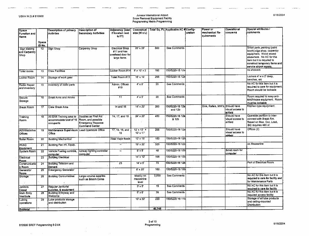
• Administrative offices for supervisors and mechanics, locker room, emergency first aid room, lunch/training room, field electrical, signs and carpentry areas, lavatories, and kitchen/galley space, and services spaces such as mechanical, electrical and telecom are included. The sign-making function has been combined with carpentry to reduce the size
City and Borough of Juneau Conceptual Design Report Juneau International Airport Snow Removal Equipment Facility
- 6 -
as much as possible. Additional support areas related to more industrial “shop” activities include the follow spaces:
o Maintenance areas including repair and maintenance bays, a wash bay, and lubrication bay. It is important to note that at the time AC-150/5220-18 was written, lubrication could occur in the equipment storage areas of the building. In fact, a number of repair and maintenance–related tasks such as lubrication, parts exchange, and welding could be performed where vehicles were being stored. That is no longer the case; the governing building codes (2000 International Code series, National Fire Protection Association, and National Electrical Code) do not allow any work of this sort to occur in vehicle storage areas without adopting very expensive Occupancy adjustments to account for higher fire and hazards exposure potential. Therefore, the utility FAA ascribed to equipment storage areas in the past no longer exists. Unless the equipment storage areas are constructed under the more restrictive Occupancy (and Area Separations) as a shop, a significant construction cost premium will be incurred due to the fire protection and ventilation (and make-up air) requirements. For that reason, a light-duty maintenance bay to be used for these purposes has been added to compensate for the loss of the work area in the equipment storage area, as shown in even the most-current ACs. Additionally, the ACs indicates wash bays as being located within the larger equipment storage areas. Experience has proven this to be a problematic philosophy, particularly with the electronic technology onboard today’s equipment: moisture should be eliminated from equipment storage areas as much as possible to make the equipment storage facility truly effective in protecting the stored vehicles from moisture. For that reason, a separate wash bay has been included.
o Support spaces include parts storage, welding area, major power tools, tire repair, and tire chain installation areas. Other spaces needed include space for painting the large snowplow blades annually, small parts painting, and space for the airports’ small sandblast booth. Other critical areas include secure storage area, and an emergency operations room. The latter is combined with the training room. It is important to note that per the ACs, all existing SREF facilities are to be made Americans with Disabilities Act (ADA) compliant to the maximum extent possible. The existing JNU facility is incapable of achieving this goal due to the locations and of locker and crew areas and the structural limitations of the building.
o Equipment (Warm) Storage for vehicles is needed to keep them in a ready-to-go state. Additionally, because of the sensitive electronics the newer vehicles are now equipped with, covered and heated space is needed to protect the investment. The wash bay has been conceptually configured as part of the warm storage due to the frequency of use and need to wash each vehicle before it is parked at the end of each shift. The size of the facility is easily adjustable given the suggested pre-engineered building construction type. All FAA-authorized vehicles will be positioned within the building.
o Materials Storage (Cold) for deicer products includes CG-90 and urea. Juneau faces several factors that other airports do not: shipments arrive in the summer and must be stockpiled for the winter and re-supplies during the winter are extremely expensive (and slow) due to water-only access. Further complicating matters are the typically moist maritime conditions that cause deicers to “cake” if not controlled. For these reasons, both urea and CG-90 are delivered in shipping containers during
City and Borough of Juneau Conceptual Design Report Juneau International Airport Snow Removal Equipment Facility
- 7 -
the late summer configured in 1-ton bags. CG-90 is used directly from these large 5’ x 5’ x 4’ industrial bags and must be kept warm once opened to the air – the trucks either immediately distribute the product or are kept inside waiting for the next application opportunity. The urea must be mixed into a liquid solution in order to be effective locally and efficiently applied to operational surfaces. The system proposed here to accomplish this goal utilizes a minimum of interior space and can be operated by a single person versus a crew the three the operation currently requires. All unloading of incoming raw product (freight) would occur inside to avoid wetting the products. Loading for distribution would occur outside in a contained area with collection and filtration. The current loading operation has no containment. Due to the excessive dust associated with loading CG-90, the loading provisions include controlled interior and exterior operations. The handling, storage, and loading operations for these materials is designed to utilize efficient, labor saving devices that will also increase the safety of working with these compounds. A detailed description of these operations is included.
Future Projections
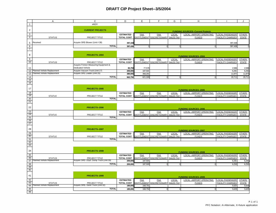
Future projections for the equipment fleet to adequately maintain the runways, taxiways, and aprons include additional vehicles as well as replacement of aging fleet vehicles. The 5-year CIP for equipment replacement includes friction-measuring equipment and support vehicle, vacuum truck, loader, 20-yard dump truck, and sand truck, reference Appendix V.
Based on the existing and proposed storage needs for new and replacement equipment, associated materials storage and support areas consistent with the ACs, the required facilities include:
• Lubrication bay for daily lubrication, fluids exchange, and light painting (blades and buckets) with access to tire storage mezzanine.
• Maintenance bay for regular preventive maintenance, tire changes and chains, parts exchange and simple repairs, including electrical, welding (with curtain and ventilation), and emergency repairs.
• Mechanics bay for all scheduled heavy work and emergency repairs with adjacent hand and power tools, parts room/office, major stationary tools, and access to storage mezzanine. A 5-ton overhead crane serves this and other bays with a hook height appropriate for maintenance to all JNU equipment.
• Supervisors and foreman’s offices with direct views to airfields and secure storage for bird-hazing operations.
• Break room with an authorized kitchen/galley and adjacent training room. This area will accommodate the authorized Emergency First Aid room and serve as an Emergency Operations Center should a crisis require mobilization of major regional resources. An operable wall can subdivide the space normally.
• Field electrical and radio room provides storage and repair space for airfield lighting, vehicle-mounted and base-unit radios, and sensitive electronics parts exchange. At the current time, JNU does not repair high-tech electrical gear on-site, but simply exchanges critical parts, as needed.
City and Borough of Juneau Conceptual Design Report Juneau International Airport Snow Removal Equipment Facility
- 8 -
• Signs and carpentry room allows for the fabrication and maintenance of airport signage, temporary barricades, small and medium wood products, and emergency repairs. The space has an overhead door for loading and unloading heavy or awkward items under cover.
• Base building functions such as the mechanical and electrical rooms, special systems rooms to hold the “GasBoy” fuel inventory control computer, the facility server, and telecom equipment, and well as toilets and locker areas are well positioned for efficiency and access.
• Wash bay is used before vehicles are put away at the end of each shift and is connected to the equipment storage space for the convenience of operators. The space will be equipped with a pressure washer and wash-water reclaim system as part of the airports commitment to minimizing the long-term impact of this project. Normally, equipment is washed after use and before storage. If the equipment breaks during wintertime use, it will typically be washed prior to repair. Washing operations use a lot of water and many times powerful cleaning agents. These are used to aid in dirt, grease, and urea removal. Capturing and recycling the wash water will reduce the projects’ contribution to the sanitary waster flow. The bay will utilize its own ventilation system and be equipped with a heated slab to eliminate moisture and reduce its migration to the equipment storage area.
• Equipment (warm) storage area is a pre-engineered metal building with a heated concrete slab (to evaporate water and utilize waste heat from the urea processing heating plant) and minimal ventilation. The goal of this space is simply to protect the equipment and provide for its rapid deployment to the airfield.
• Materials storage area (covered) is comprised of three separate parts: Sand, urea, and CG-90.
o Sand will be stored in a stand-alone building. This is the most cost-effective building type to contain sand because they are engineered with specific capabilities, code exceptions, and materials. Operationally, these facilities are distinct from other buildings on the airfield and maneuvering room for the large distribution vehicles requires separation. The configuration will be an efficient round or rectangular building configuration. A light-duty sand conveyor will efficiently stock the facility and equipment will load the spreader vehicles.
o Urea is received and stored in 1-ton bags which must be opened and mixed in a vat of warm, circulating water before being stored in a large 12,000 gallon tank for loading into distribution vehicles when needed. The facility also houses CG-90 with an efficient drive-thru configuration and overhead crane to stack and retrieve the bags. The crane will transport urea bags to a semi-recessed mixing tank where they will be opened and dissolved into the needed solution. Afterward, the urea solution is stored inside a heated tank until needed on the airfield, at which time it is pumped into specialized trucks waiting outside. This process will require a single staff person, working in a controlled, well-lit environment. It replaces an intensive, three-person, round the clock, outdoor, and dangerous urea mixing operation that also requires substantially more holding capacity due to the very slow preparation times: the proposed system will prepare urea solution in less than 1/3 the time and with 1/3 the
City and Borough of Juneau Conceptual Design Report Juneau International Airport Snow Removal Equipment Facility
- 9 -
staff. As a bonus, waste heat from the heating plant required for urea solution mixing can also be used to provide in-floor heat to the equipment storage building.
o CG-90 is a powder that must be kept dry and heated (minimally, to avoid caking) once opened. A covered vehicle loading area is proposed. This area will be served by a monorail crane. It will lift bags and suspend them over the spreader trucks for loading – this process will also take only a single person (operator) with no heavy equipment. The efficiency and safety of this design will reduce operational costs and should decrease runway turn times.
SAFETY AND EFFICIENCY
Safety and efficiency are sometimes competing interests. Facilities that do not serve basic operational needs are at odds with both. One of the goals of this project is to enhance the efficiency of the airfield operations while also increasing staff safety by providing facilities designed specifically to support equipment, operations, and JNU’s unique environmental conditions. No known Occupational Safety and Health (OSHA) violations have been documented, but this may only be due to lack of inspections.
Staff
Staff at JNU do a lot with a little and have been doing so for years. For instance, the operators routinely perform the preventive maintenance (check oil, replace wipers, etc) on the vehicles they drive. This allows the mechanic to focus on the more important issues. The dedication JNU team as a cohesive unit is exceptional, particularly in light of the challenges caused by the current facilities’ size, design, and location at JNU. The group routinely pulls together to overcome operational and logistical challenges. The urea mixing operation is a good example of performance under pressure: it takes 3.5 trained and knowledgeable staff members 24 hours to make a batch of the urea solution that is ultimately spread on operating surfaces. Frequently they are working in stormy conditions, always outside, and must transport the urea bags from across the airport to the rear of the Equipment Shop. The new facility will allow these specific improvements in working conditions and efficiency:
• A well-lit and ice-free safer environment. • Fewer people making urea. • Better quality control of urea solution. • More efficient urea mixing equipment. • Less urea tank storage required due to faster mixing times. • Lower tank heating costs. • Better environmental controls for urea and CG-90. • Waste heat used to heat equipment storage building. • Consolidated operations.
Equipment
Equipment at JNU is maintained as best can be done under the circumstances. Some equipment will not fit inside and must therefore be maintained outdoors, sometimes under tarps. The new facilities will allow all maintenance to occur inside. The overhead doors will be large enough to accommodate the largest equipment and the spaces will be organized to support efficient workflows.
City and Borough of Juneau Conceptual Design Report Juneau International Airport Snow Removal Equipment Facility
- 10 -
Materials
Materials storage is a major concern at this airport. As noted above, the urea mixing operation is a significant wintertime activity that takes considerable time. The safety issues associated with materials that are housed in one area, transported to another, prepared in an exterior, often slippery environment, cannot be overstated. The proposed design will improve safety dramatically. For instance, the urea mixing operation now done outside, using a loader, a knife on a stick, and canoe paddles on and around a 16-foot-tall steel tank, will be accomplished mechanically from the floor of a temperate covered building. The difference will be felt immediately and is expected to have very positive returns to the airport. Staff will also be spared this dangerous task.
Access and Circulation
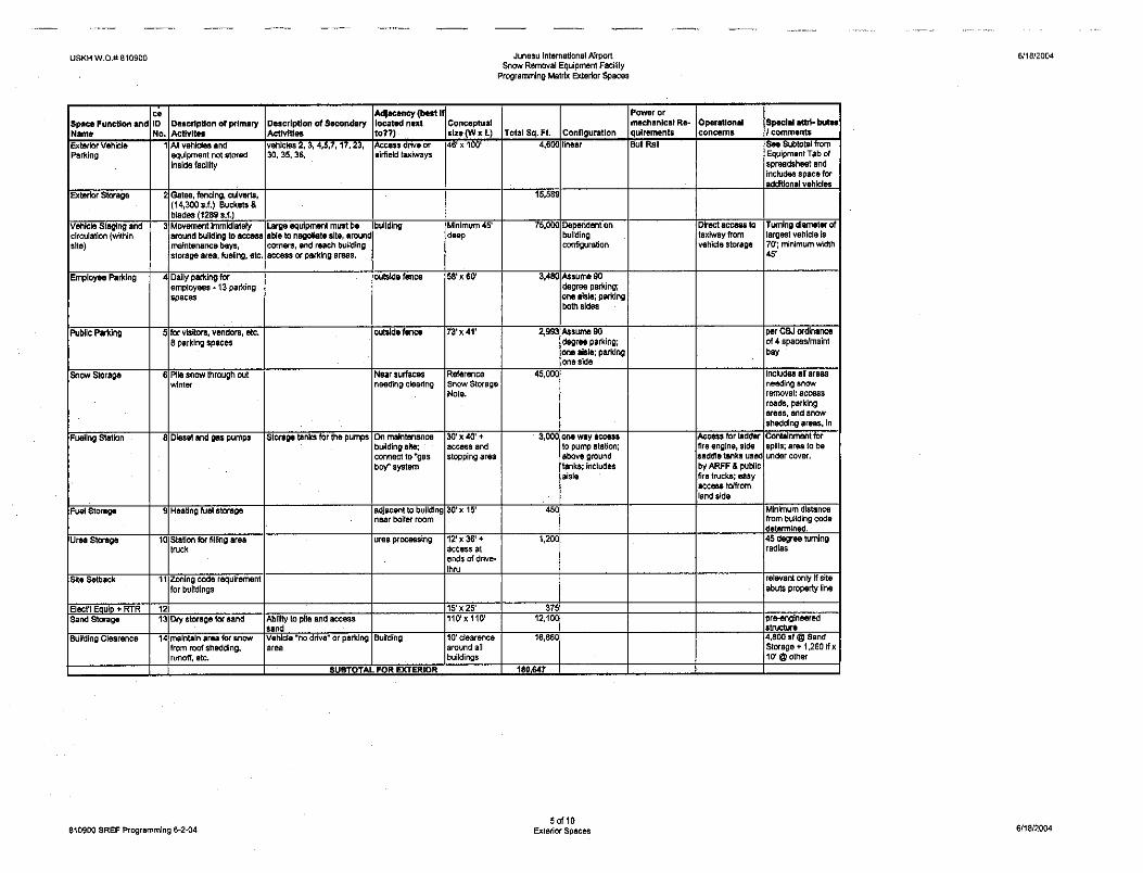
Access and circulation is key to having an efficient airfield maintenance operation. The proposed site and facilities provide enough room for consolidation of all SREF components in a footprint of approximately 6.7 acres, including a sand storage building and the following exterior storage areas: gravel and D-1, bone yard and fabrication supplies, outdoor vehicle storage, access to all doors and drives, and safe maneuvering areas. Inside the buildings, safety is carefully considered by designing into the facilities adequate storage and circulation space. The building interiors are similarly well positioned to allow enough space for safe storage of tools, inventory, and equipment, and to support operations.
Currently, JNU staff must replace broom cores outside due to lack of ceiling height, overhead crane height, and bay width, to support this task. The staff built a special jib (boom) for the #980 loader extending its reach to approximately 12 feet. This allows the core to be lifted high enough to shake the core up and down to force individual broom parts (wafers) off the core. Sometimes this does not work and then a torch is needed to remove the wafers. After the wafers are removed, staff sets the core upright next to the edge of the second floor of the sand shed. The wafers are slid onto the core one at a time (this process is very dangerous). This whole process takes two men about 7 hours to complete. Every year this process is completed two to three times per broom, per winter. JNU currently has three brooms, resulting in approximately 100 hours of labor for this task. A new facility with an appropriately positioned overhead crane could cut expended manhours for this task to less than half of the current time with a substantial decrease in risky indoor loader operations.
Size of Site
The size of the site is determined by the following rationale and is supported with the matrices in Appendix III:
• All snow removal equipment needs to be able to access the runway efficiently from a variety of locations where these vehicle and staff are to be consolidated. These include, the Equipment Warm Storage area, the shops (maintenance bays), and the fueling area. The width of the access drives is based upon the sizes and turning radii of the equipment. The basis of design is 45 feet for drives and 75 feet at intersections. A turning radius of 70 feet is needed for the runway brooms, plows, snow blowers, and other large equipment.
• As previously noted, maintenance materials and equipment are currently stored at a variety of locations distributed around the airport. Many of these items are quite large,
City and Borough of Juneau Conceptual Design Report Juneau International Airport Snow Removal Equipment Facility
- 11 -
and include blades, buckets, fencing material and emergency oil spill response equipment. To reach the materials, personnel use existing roads, aprons and taxiways. Concentrating all materials storage together on one site will reduce the time staff spends traveling around the airport to collect items needed each day, and increase the staff’s efficiency. A consolidated facility must have a number of internal drives to safely navigate equipment. Additionally, roads and ways generally used by other vehicles are not desirable for safety reasons.
• The fueling station will be sized to accommodate the equipment the airport currently has. When needed in future years, it could be expanded. The request is for both diesel and gasoline storage to accommodate the various vehicle types routinely operated. Local conditions suggest that only aboveground tanks will be effective long-term, as these can be monitored more closely for leaks. All tanks will be diked. The pump and fuel tank system will be self-sufficient, and within the consolidated facility. It is also important for the fueling station to be located so as to accommodate the range of vehicle sizes and configurations, and their ready access to the airfield.
• The existing hangar/sand storage facility must be replaced. A new facility to accommodate a season’s worth of sand is included on the site. The size has been verified based on annual usage. It is also desirable to co-locate this function with the other SREF components to increase staff and equipment efficiencies, and improve re-fill and distribution times.
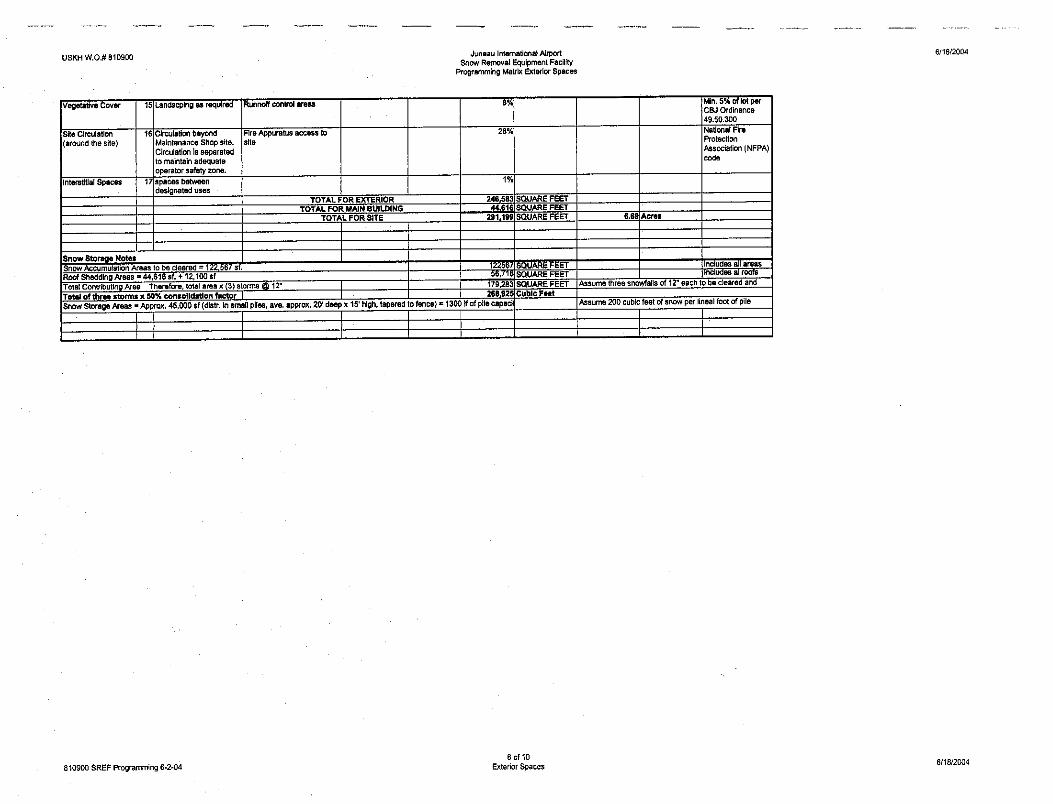
• The design includes areas allocated to the storage of snow accumulated from clearing operations on the immediate site and access roads/taxiways. In addition, small accumulation buffers around the building perimeter ensure that snow suddenly falling from roofs does not impede traffic and will not, in and of itself, require additional snow moving after every snowfall. However, after storms, these areas should be cleared to make room for additional snow. This designated buffer area is for roof snow accumulation and is a pedestrian and vehicle safety area. One of the program requirements was for a nearby off-season driver training area. It is anticipated that the snow storage areas could be used for this purpose in the summer months. In order to determine the square foot area necessary to accommodate historical snow volumes, JNU’s current plowed areas and snow storage capacity was assessed. The proposed development areas were also determined. The footprints of Part 135 and Part 121 ramp snow storage spaces were measured and are indicated below:
Part 135-47,000 sq ft of snow storage pilled 40 feet high Part 121 -47,700 sq ft of snow storage pilled 40 feet high
The total acres plowed for these two spaces is18 acres, split equally between the two. Parts 135 and 121 are relatively unrestrained areas where loaders and excavators can easily pile the snow up to 40’ high. The proposed snow storage areas are in close proximity to the site, can be cleared by less sophisticated equipment, and are smaller than other snow storage areas. Therefore configured such that 40’ high storage piles will not be possible. Based on the proposed layout, snow piled 15’ high is reasonable. Based on this information, the snow storage space included in the attached matrix (45,000 square feet) is needed to accommodate the new SREF development, including access ramp, storage areas, and circulation roads.
City and Borough of Juneau Conceptual Design Report Juneau International Airport Snow Removal Equipment Facility
- 12 -
• In keeping with best-management practices (BMPs), all stormwater and snow melt accumulated on the site will be drained within the boundaries of the facility. At this stage it is not known whether underground structures, bio-swales or some combination of the two will be used to control runoff and facilitate primary treatment. However, designated areas for these functions are planned. A more definitive design for these features will emerge as additional information is gained about the topography and soil conditions of the preferred site.
• An adequate site for a SREF must have access from both the airfield and the public side of the airport, as well as adequate circulation space. For this reason at least two means of entrance are needed. This is also a requirement for effective fire fighting. The exact size and shape of these drives is dependent on the configuration of the actual site. As stated above, internal circulation for this large equipment is preferred to limit conflicts with other types of traffic, as well as maintaining a safe and effective operational areas.
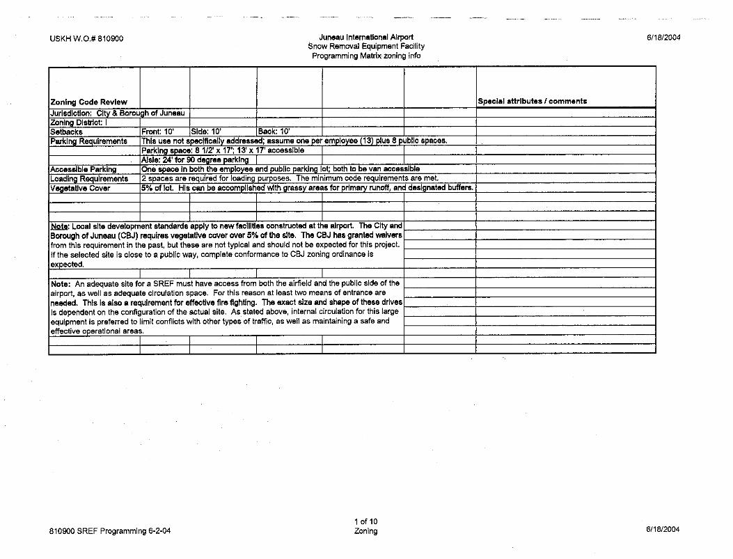
• Local site development standards apply to new facilities constructed at the airport. The City and Borough of Juneau (CBJ) requires vegetative cover over 5% of the site. The CBJ has granted waivers from this requirement in the past but these are not typical.
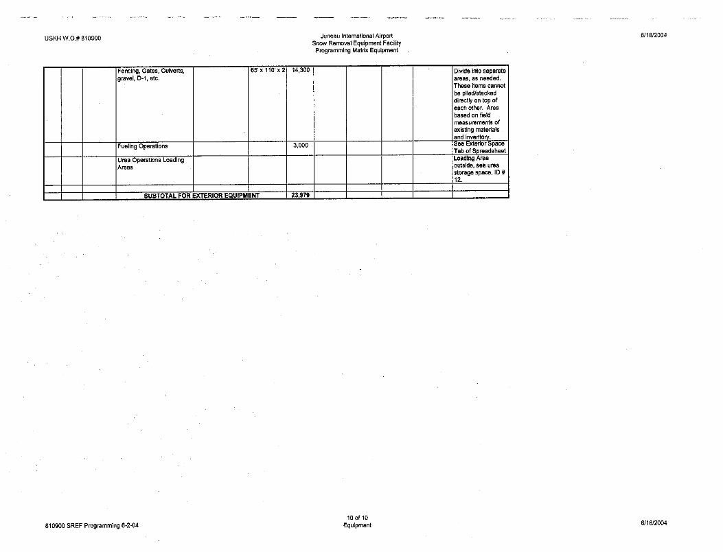
• In contrast to the airports’ current operations, a designated loading area for staging shipments of chemicals, sand, equipment, supplies, is included. Chemicals and sand arrive in containers and are stored on site for up to five weeks while the cargo is unloaded and stored inside. Current operations make use of a variety of inefficient locations to accommodate the incoming containers. The receiving, unloading, and storage of the Urea and CG-90 has been a real problem in the past because up to 24 trailer loads of these supplies are delivered in the late summer and fall. Handling this volume of containers requires that lay-down space be available. To accomplish the unloading, containers may be temporarily staged in open areas or staged within the overhead doors of this building so small forklifts can quickly remove the contents while the overhead crane stacks them for later use.
• To promote a safe and secure working environment, visitor parking is provided outside of the airport fence. Maintenance employees and visitors to the facility alike will use this lot.
• A number of vehicles in the Field Maintenance fleet do not require warm storage. These will be accommodated outside. These include a tractor and mowing attachments, spill response equipment, small seasonal power tools (lawn mowers, etc.), an excavator and its trailer, small passenger vans, etc.
• There are a variety of smaller items and functions that are included on the site plan. These include facility heating fuel tanks and access, transformer, emergency generator, and the FAA’s remote transmitter and receiver (RTR) equipment.
FUNDING THE NEED
Funding the need for new SREF, deicer, and sand storage facilities at JNU relies principally on funding entities to understand how undersized and dilapidated the existing facilities are. General understanding of the need exists and commitments by all possible funding sources must be secured.
City and Borough of Juneau Conceptual Design Report Juneau International Airport Snow Removal Equipment Facility
- 13 -
CONSTRUCTING A REPLACEMENT SREF
Building a facility that will serve JNU into the future should allow for the addition of both equipment and staff as maintenance needs change over time, if more aviation surfaces are needed. While the prospect of major airfield growth is not predicted, moderate increases are, and when combined with expected future adjustments in equipment size and its immediate mobilization, constructing a facility with the potential to expand is recommended. The concept design includes site and facility organized to expand without disrupting ongoing operations. For instance, if another maintenance bay is needed, one is simply added to the end of the building and the proposed entry relocated accordingly – no functions are disrupted. Similarly, if more equipment storage or materials storage area is needed, the end of the pre-engineered metal building is merely extended as needed.
Site
Planning for the construction of the SREF site and facilities is a complicated process in part due to the ongoing environmental review and permitting process. At this time, an actual site has not been selected. As such, the site plan includes provisions to accommodate all current or planned field maintenance assets foreseen at this time. The attributes include utilities to support new maintenance, equipment warm storage, deicing materials storage and processing, sand storage buildings, fueling facilities, deicer loading pads, and secure outside ware-yards and equipment parking. Additionally, the FAA’s RTR equipment facility will be located on this site, measuring approximately 10’ by 10’ with integral antenna and fence. New paved roads, directly off active apron surfaces, and connecting only where appropriate to the public road system, afford access and circulation. Drainage and environmental protections will be better understood once the proposed site’s topography is known. Generally, all drainage will be kept on site and treated by utilizing a BMP approach to stormwater runoff, consistent with other JNU operations. Where chemical loading and fueling are concerned local containment will be employed.
Facilities
The attached drawings illustrate conceptual site and floor plans based on information gathered from JNU staff and experience with similar airports. The following list is a conceptual–level outline of the components involved and will be refined as the site and building design are further developed. The definitions are based on “CSI Uniformat” descriptors (industry systems definition standard), which present a logical approach to describing a project from this early stage:
Substructure:
• Includes Foundations and Slabs on Grade.
o Foundations – determined by geotechnical investigation. Likely to be spread footings and frost walls of poured in place concrete.
o Special Foundations will include the below-grade urea mixing tank. This will be constructed to resist intrusion of water table.
o Slabs on grade – Typically 4” to 6” thick, reinforced concrete slabs sloped to drain. Slabs in warm storage and work bays will be heated with in-slab radiant tubing and a low-temperature water and glycol solution.
City and Borough of Juneau Conceptual Design Report Juneau International Airport Snow Removal Equipment Facility
- 14 -
Shell
• Includes Superstructure, Exterior Closure, and Roof coverings. The section titled “Other Building Construction” contains detailed descriptions of the equipment storage and materials storage areas.
o Floor construction above slabs on grade include mezzanine-level storage areas of metal decking and poured concrete.
o Roof construction will utilize two different systems:
Shop building roof will be supported by structural steel fabricated to meet design requirements of structural capacity, space flexibility, and expandability. Main structural frames will be approximately 30 feet on center with metal purlins, and metal decking. Roofs are sloped to avoid standing water. The equipment and sand storage buildings will also utilize sloping roofs, but these will be un-insulated metal. The equipment building will use proven batt insulation below the metal roof panel.
Roof coverings and openings for the shop building are composed of adhered insulation, adhered membrane, drainage fabric, and heavyweight pavers. Parapets and flashings shall have flashings and metal copings. Between buildings seismic and expansion joints will be provided.
o The equipment storage and materials storage areas are more fully described under Other building construction, but will generally be sloped metal panel roofing on a pre-engineered metal building system.
o Exterior closure for the shop building includes walls, windows, and doors.
Walls consist of metal panel siding on a weatherproof substrate, minimum 6-inch metal studs, fiberglass batt insulation, vapor barrier, and gypsum board, or pre-finished sanitary panels (locker, restrooms, training, break, etc).
Windows consist of anodized, thermally broken aluminum triple pane windows with offset center space (to reduce noise), and highly efficient low-E energy coating.
Doors include personnel and vehicle doors. Personnel doors will be insulated steel with factory-applied baked enamel coatings to resist atmospheric decay. Overhead vehicle doors will be upward-acting sectional doors and roll-up doors (at Equipment Storage).
Interiors
• Interiors are composed of interior construction, stairways and interior finishes.
o Interior Construction
Partitions will be metal studs with gypsum wallboard, sanitary panels, and industrial-quality wainscoting where appropriate. An operable partition with
City and Borough of Juneau Conceptual Design Report Juneau International Airport Snow Removal Equipment Facility
- 15 -
sound attenuation will be provided at the break/training area. Interior windows will be provided at shop areas for safety and monitoring. Safety railing will be provided at mezzanines.
Doors will be painted, commercial quality steel, and where appropriate, be equipped with vision lites for safety.
Specialties will include visual display boards, limited bathroom partitions and screens, louvers and vents as required for mechanical systems, wall and corner guards, signage, lockers, storage shelving, toilet accessories, and limited closet accessories.
o Stairways
Construction of the two mezzanine access stairs will be metal, industrial ladder-type, with handrails on both sides and finished with paint. Treads will be non-slip.
o Interior Finishes
Wall finishes will be paint and pre-finished where ready-made products are specified.
Floor finishes include sealed concrete, regular and anti-static vinyl composite tile (VCT) where appropriate.
Ceiling finishes include paint for industrial spaces and limited acoustical, lay-in tile for offices and break/training rooms. Toilet, electrical, mechanical, and special systems areas will have painted gypsum board.
Services
• Services are composed of conveying systems, plumbing, heating, ventilating, and air conditioning (HVAC), fire protection, and electrical systems:
o Conveying systems include bridge cranes for both the shop building and the Materials Storage Building, 5-ton and 1.5-ton respectively. The CG-90 loading operation will employ a 1.5-ton monorail lift. No elevator access to the mezzanines is required.
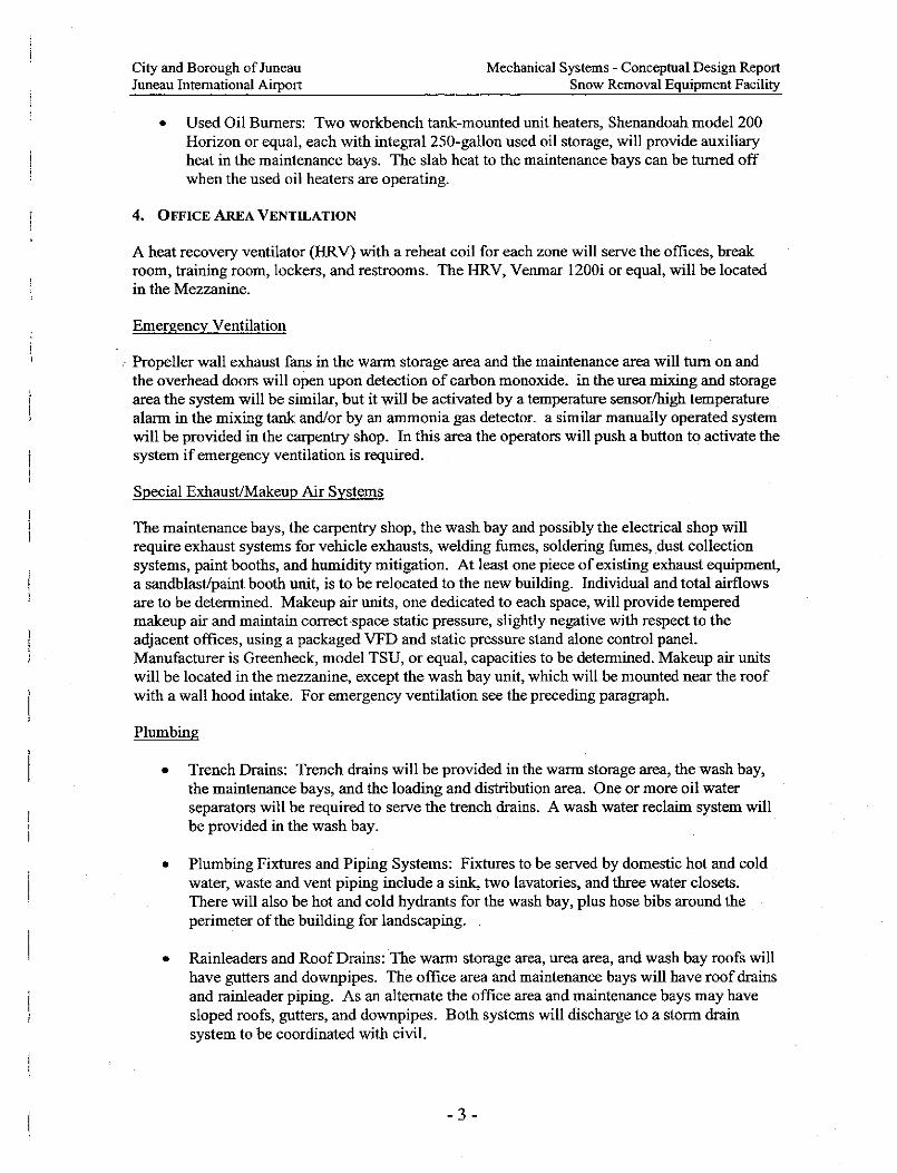
o Plumbing Systems (see Appendix)
o HVAC Systems (see Appendix)
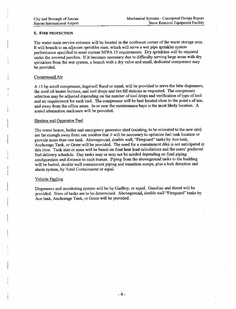
o Fire Protection Systems (see Appendix)
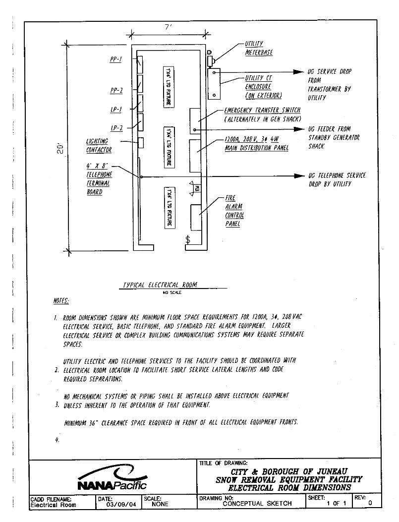
o Electrical Systems (see Appendix)
Equipment and Furnishings
• Equipment
City and Borough of Juneau Conceptual Design Report Juneau International Airport Snow Removal Equipment Facility
- 16 -
o Commercial equipment is not anticipated on this project, with the possible exception of a washer and dryer.
o Institutional equipment includes provisions to connect audio-visual equipment, but none will be provided.
• Vehicular Equipment
o Vehicle lifts include a 50-ton floor-mounted hydraulic lift similar to a Stertl-Koni scissor type lift. A tire change machine will be relocated to the new facility.
o Shop equipment includes a variety of tools including a metal lathe, a combination sandblast and paint booth, drill and hydraulic presses, bench grinders, parts washers, etc., to be relocated from the existing shop.
• Other equipment includes residential-grade kitchen equipment and cabinets.
• Furnishings
o Fixed Furnishings include limited window shades, and several grilles and mats for entry doors.
o Moveable Furnishings are not anticipated. Needed desks and accessories will be furnished by JNU.
Other Building Construction
• Includes equipment storage and materials storage buildings, as well as the sand storage building. These are to be pre-engineered buildings.
Special Construction
• Pre-engineered metal buildings are an efficient way to provide basic structures. These typically are specified with certain characteristics and are available with many options. For the equipment and urea/CG-90 buildings, simple clear-spans, with metal panel roof and walls are appropriate. Doors are specified elsewhere. The sand storage building could be this type, or it could be a dome configuration. Dome buildings are more efficient but, depending on location, may not be consistent with local development standards if adjacent to public ways or other land-use districts.
• Special facilities include the urea processing area. Although described in detail elsewhere, this system will generally be composed of tanks, pumps, a water-heating boiler, measuring and monitoring devices. Reference Appendix VI.
• Special controls and instrumentation include the GasBoy fuel management system, all fuel system monitoring and measuring devices, building automation and control systems, fire alarm and annunciation, Fire suppression and monitoring, and lube products distribution and monitoring devices. Reference Appendix VII.
City and Borough of Juneau Conceptual Design Report Juneau International Airport Snow Removal Equipment Facility
- 17 -
Site Preparation
• Building sitework includes site preparation, site improvements, site plumbing utilities, site HVAC, site electrical utilities, and other site construction.
• Subsurface investigation will be accomplished once a site is selected. As part of the investigation, the seismic qualities of the existing soils constitution will also be assessed.
• Site clearing involves stripping, clearing, and grubbing, as well as shrub and tree removal. However, depending on the site selected, site remediation may need to be carefully executed to assure environmental compliance.
• Site demolition and relocations may also be involved depending on the specific site selected.
• Site earthwork involves grading, excavation, backfill, and compaction, soil stabilization (for steeper sites), and erosion control.
• Hazardous waste remediation will likely not be a problem, but the site investigation will include an assessment of potential materials present on site.
Site Improvements
• Roadways and parking area work includes appropriate base courses, flexible paving, potentially curb and gutter, and signage.
• Pedestrian paving will be concrete and limited to areas leading from parking lots to the building.
• Site development work includes fences and gates (including gate controllers), other exterior signs, and flagpoles.
• Landscaping work will be consistent with CBJ development standards and include soils preparation, tree and shrub planting (or transplantation), lawns and grasses, trees, plants and ground covers.
Site Plumbing Utilities
• Site water supply and distribution will be accomplished by extending airport utilities to the selected site. The mains must be sized for the required fire flow for the Occupancy and building construction type, per the IBC and National Fire Protection Association (NFPA).
• Site sanitary sewer systems will also include the extension of airport services. However, depending on topographical alignment, either gravity or force-main systems will be provided.
• Site storm sewer systems provisions must be made once a site is selected. It is JNU’s intention to provide a best practices solution in this regard. The solution to a given site may not be storm sewerage piping at all, but a series of bio-filtration and settling ponds. This issue requires detailed assessment as site(s) are considered in more detail.
City and Borough of Juneau Conceptual Design Report Juneau International Airport Snow Removal Equipment Facility
- 18 -
• Site Fuel distribution systems will be utilized to a limited degree. First, all tanks are expected to be above ground. This will allow visual monitoring and is expected to save substantial costs over buried systems. Fuel oil for the buildings heating and urea processing systems will pumped to small day tanks at two locations. The equipment fueling tanks will be connected to the pumps. Reference Appendix VI. Gasoline and diesel fuel will be provided.
• Site special plumbing systems are not anticipated.
• Site heating, heating, ventilation, and air conditioning (HVAC) systems (such as buried vaults) are not anticipated.
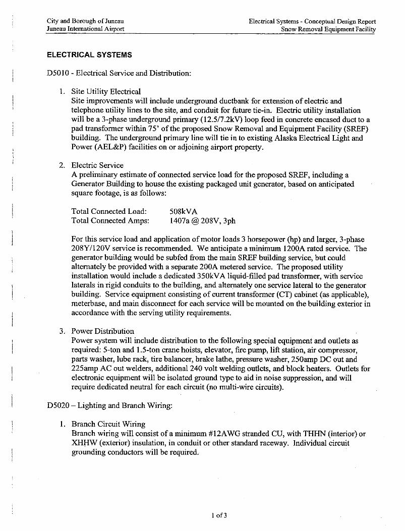
• Site electrical utilities reference Appendix VII.
o Site electrical distribution
o Site lighting systems
o Site communications and security systems
o Other site electrical systems
Bull rail and headbolt heaters
• Other site construction
o Service tunnels are not anticipated.
o Other site systems and equipment are not anticipated.
City and Borough of Juneau Conceptual Design Report Juneau International Airport Snow Removal Equipment Facility
- 19 -
3. CONCLUSION
Past assessments have shown that JNU is long overdue for a new maintenance facility. This report finds that aside from simply a new building to fix and store vehicles, consolidating all the maintenance group’s assets in one location will have a substantial and positive operational impact.
This conceptual design report was developed as a result of site visits, interviews, and assessments of current operations, equipment, facilities, as well as challenges to JNU assumptions. In short, the consultant worked closely with JNU to arrive at conclusions that make sense to correct the existing problems and position the airport for long-term success.
APO TERMINAL AREA FORECAST DETAIL REPORT Forecast released 2/18/04
JNU
AIRCRAFT OPERATIONS
Scheduled Enplanements Itinerant Operations Local Operations Year AC Comm. Total AC AT & Comm. GA Mil Total GA Mil Total Total OPS Total Inst.OPS Based Aircraft
REGION:AAL STATE:AK LOCID:JNU CITY:JUNEAU AIRPORT:JUNEAU INTL 1996 235778 91169 326947 7574 109054 18365 609 135602 12714 128 12842 148444 9546 3571997 229716 85005 314721 7198 98048 17398 498 123142 13228 92 13320 136462 9260 3571998 238504 44603 283107 7585 107069 19469 592 134715 16291 58 16349 151064 10426 3571999 243525 37461 280986 7774 106165 18691 707 133337 14951 56 15007 148344 10563 3572000 251933 35967 287900 8391 103418 17599 798 130206 15317 108 15425 145631 11595 3572001 260177 34088 294265 9175 103383 16569 586 129713 13820 98 13918 143631 12638 3302002 251280 14904 266184 9398 91143 14830 682 116053 14295 42 14337 130390 12966 3302003* 246587 29638 276225 9311 90529 14998 619 115457 12846 196 13042 128499 12531 3302004* 261208 31238 292446 9539 92062 15160 619 117380 12985 196 13181 130561 12801 3352005* 269011 32881 301892 9751 93596 15323 619 119289 13124 196 13320 132609 13054 3382006* 276814 34524 311338 9963 95130 15485 619 121197 13263 196 13459 134656 13308 3422007* 284617 36167 320784 10175 96663 15647 619 123104 13402 196 13598 136702 13562 3452008* 292419 37810 330229 10387 98197 15810 619 125013 13541 196 13737 138750 13816 3482009* 300222 39451 339673 10599 99731 15972 619 126921 13680 196 13876 140797 14071 3532010* 308025 41094 349119 10811 101265 16135 619 128830 13820 196 14016 142846 14325 356
2011* 315828 42737 358565 11023 102798 16298 619 130738 13959 196 14155 144893 14580 3592012* 323630 44380 368010 11235 104332 16460 619 132646 14098 196 14294 146940 14834 3632013* 331433 46023 377456 11447 105866 16623 619 134555 14238 196 14434 148989 15087 3662014* 339236 47666 386902 11659 107400 16786 619 136464 14377 196 14573 151037 15342 3692015* 347039 49307 396346 11871 108934 16948 619 138372 14516 196 14712 153084 15596 3742016* 354841 50950 405791 12083 110467 17111 619 140280 14655 196 14851 155131 15851 3772017* 362644 52593 415237 12295 112001 17274 619 142189 14795 196 14991 157180 16105 3802018* 370447 54236 424683 12507 113535 17436 619 144097 14934 196 15130 159227 16359 3842019* 378250 55879 434129 12719 115069 17599 619 146006 15073 196 15269 161275 16613 3872020* 386053 57522 443575 12931 116603 17762 619 147915 15213 196 15409 163324 16869 392 COMMENT : null
JUNEAU INTERNATIONAL AIRPORTDETERMINATION OF APPROVED EQUIPMENT
UTILIZING PERTINENT FAA ADVISORY CIRCULARS
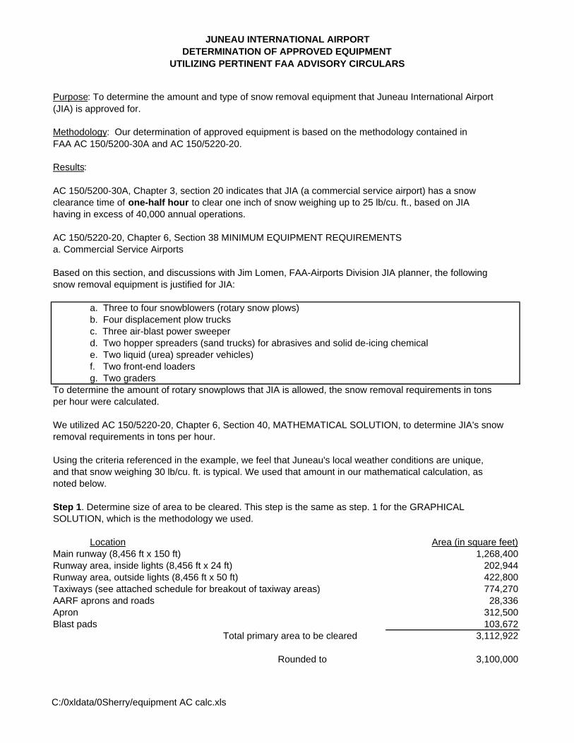
Purpose: To determine the amount and type of snow removal equipment that Juneau International Airport(JIA) is approved for.
Methodology: Our determination of approved equipment is based on the methodology contained in FAA AC 150/5200-30A and AC 150/5220-20.
Results:
AC 150/5200-30A, Chapter 3, section 20 indicates that JIA (a commercial service airport) has a snow clearance time of one-half hour to clear one inch of snow weighing up to 25 lb/cu. ft., based on JIA having in excess of 40,000 annual operations.
AC 150/5220-20, Chapter 6, Section 38 MINIMUM EQUIPMENT REQUIREMENTSa. Commercial Service Airports
Based on this section, and discussions with Jim Lomen, FAA-Airports Division JIA planner, the followingsnow removal equipment is justified for JIA:
a. Three to four snowblowers (rotary snow plows)b. Four displacement plow trucksc. Three air-blast power sweeperd. Two hopper spreaders (sand trucks) for abrasives and solid de-icing chemical e. Two liquid (urea) spreader vehicles)f. Two front-end loadersg. Two graders
To determine the amount of rotary snowplows that JIA is allowed, the snow removal requirements in tonsper hour were calculated.
We utilized AC 150/5220-20, Chapter 6, Section 40, MATHEMATICAL SOLUTION, to determine JIA's snowremoval requirements in tons per hour.
Using the criteria referenced in the example, we feel that Juneau's local weather conditions are unique,and that snow weighing 30 lb/cu. ft. is typical. We used that amount in our mathematical calculation, asnoted below.
Step 1. Determine size of area to be cleared. This step is the same as step. 1 for the GRAPHICALSOLUTION, which is the methodology we used.
Location Area (in square feet)Main runway (8,456 ft x 150 ft) 1,268,400Runway area, inside lights (8,456 ft x 24 ft) 202,944Runway area, outside lights (8,456 ft x 50 ft) 422,800Taxiways (see attached schedule for breakout of taxiway areas) 774,270AARF aprons and roads 28,336Apron 312,500Blast pads 103,672
Total primary area to be cleared 3,112,922
Rounded to 3,100,000
C:/0xldata/0Sherry/equipment AC calc.xls
JUNEAU INTERNATIONAL AIRPORTDETERMINATION OF APPROVED EQUIPMENT
UTILIZING PERTINENT FAA ADVISORY CIRCULARS
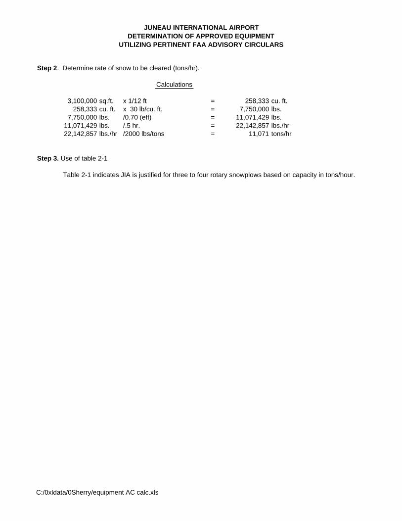
Step 2. Determine rate of snow to be cleared (tons/hr).
Calculations
3,100,000 sq.ft. x 1/12 ft = 258,333 cu. ft.258,333 cu. ft. x 30 lb/cu. ft. = 7,750,000 lbs.
7,750,000 lbs. /0.70 (eff) = 11,071,429 lbs.11,071,429 lbs. /.5 hr. = 22,142,857 lbs./hr22,142,857 lbs./hr /2000 lbs/tons = 11,071 tons/hr
Step 3. Use of table 2-1
Table 2-1 indicates JIA is justified for three to four rotary snowplows based on capacity in tons/hour.
C:/0xldata/0Sherry/equipment AC calc.xls
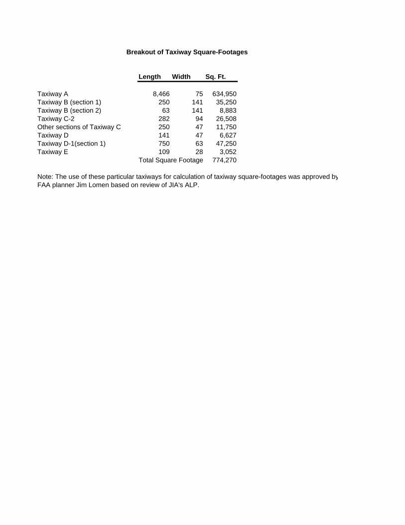
Length Width Sq. Ft.
Taxiway A 8,466 75 634,950Taxiway B (section 1) 250 141 35,250Taxiway B (section 2) 63 141 8,883Taxiway C-2 282 94 26,508Other sections of Taxiway C 250 47 11,750Taxiway D 141 47 6,627Taxiway D-1(section 1) 750 63 47,250Taxiway E 109 28 3,052
Total Square Footage 774,270
Note: The use of these particular taxiways for calculation of taxiway square-footages was approved byFAA planner Jim Lomen based on review of JIA's ALP.
Breakout of Taxiway Square-Footages
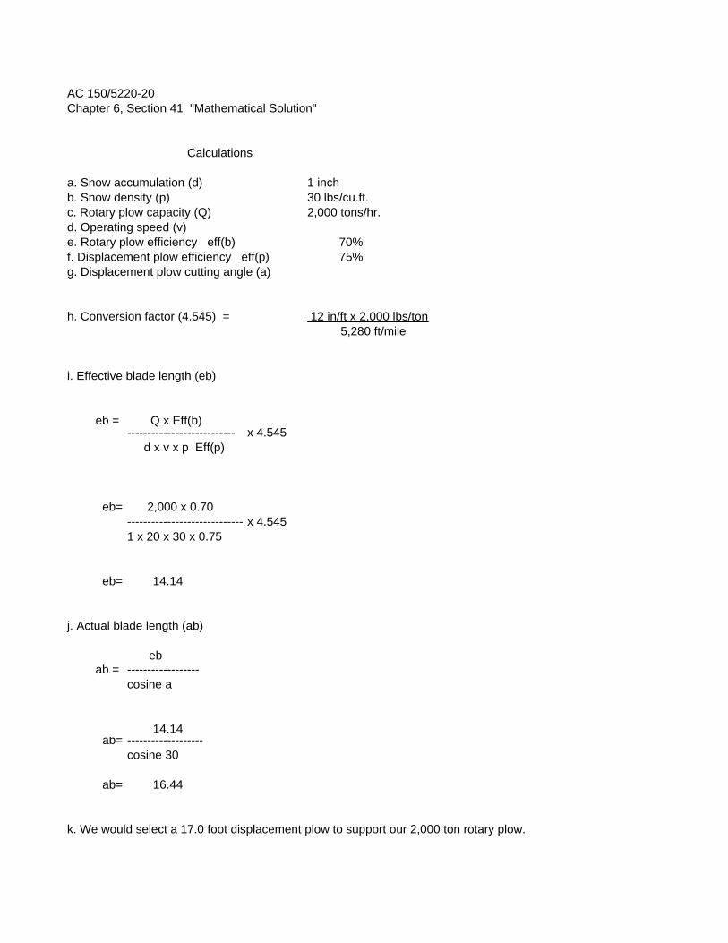
AC 150/5220-20Chapter 6, Section 41 "Mathematical Solution"
Calculations
a. Snow accumulation (d) 1 inchb. Snow density (p) 30 lbs/cu.ft.c. Rotary plow capacity (Q) 2,000 tons/hr.d. Operating speed (v)e. Rotary plow efficiency eff(b) 70%f. Displacement plow efficiency eff(p) 75%g. Displacement plow cutting angle (a)
h. Conversion factor (4.545) = 12 in/ft x 2,000 lbs/ton 5,280 ft/mile
i. Effective blade length (eb)
eb = Q x Eff(b)--------------------------- x 4.545 d x v x p Eff(p)
eb= 2,000 x 0.70------------------------------x 4.5451 x 20 x 30 x 0.75
eb= 14.14
j. Actual blade length (ab)
ebab = ------------------
cosine a
14.14ab= -------------------
cosine 30
ab= 16.44
k. We would select a 17.0 foot displacement plow to support our 2,000 ton rotary plow.
DRAFT CIP Project Sheet--3/5/2004
1
2
34
567
8
910
111213141516
17
18192021
22
2324252627
28
2930313233
34
353637383940
41
4243444546
A C D E F G H I J#REF!
CURRENT PROJECTS
Received Acquire SRE-Blower (Unit # 38) 397,438 397,438TOTAL 397,438 0 0 0 0 397,438 0
PROJECTS--2004
Acquire Friction Measuring Equipment & Dedicated Vehicle 82,750 77,578 2,586 2,586
Planned Vehicle Replacement Acquire Vacuum Truck (Unit 17) 200,000 187,500 6,250 6,250Planned Vehicle Replacement Acquire SRE Loader (Unit 20) 380,000 356,250 11,875 11,875
TOTAL 662,750 621,328 0 0 0 20,711 20,711
PROJECTS--2005
TOTAL
PROJECTS--2006
TOTAL
PROJECTS--2007
TOTAL
PROJECTS--2008
Planned Vehicle Replacement Acquire SRE--20yd. Dump Truck (Unit 30) 200,000 187,500 6,250 6,250TOTAL 200,000 187,500 0 0 0 6,250 6,250
PROJECTS--2009
Planned Vehicle Replacement Acquire SRE--Sand Truck (Unit 32) 180,000 168,750 5,625 5,625TOTAL 180,000 168,750 0 0 0 5,625 5,625
OTHER/ STATE
FAA ENTITLEMENT
FAA DISCRETIONARY
LOCAL SALES TAX
LOCAL--AIRPORT OPERATING FUNDS
LOCAL-PASSENGER FACILITY CHARGES
OTHER/ STATE
FAA ENTITLEMENT
FAA DISCRETIONARY
LOCAL SALES TAX
FAA DISCRETIONARY
LOCAL SALES TAX
LOCAL--AIRPORT OPERATING FUNDS
LOCAL--AIRPORT OPERATING FUNDS
LOCAL-PASSENGER FACILITY CHARGES
STATUS
LOCAL-PASSENGER FACILITY CHARGES
OTHER/ STATE
LOCAL-PASSENGER FACILITY CHARGES
OTHER/ STATE
FAA ENTITLEMENT
FAA DISCRETIONARY
LOCAL SALES TAX
LOCAL--AIRPORT OPERATING FUNDS
LOCAL-PASSENGER FACILITY CHARGES
OTHER/ STATE
LOCAL-PASSENGER FACILITY CHARGES
OTHER/ STATE
LOCAL--AIRPORT OPERATING FUNDS
LOCAL-PASSENGER FACILITY CHARGES
OTHER/ STATE
LOCAL--AIRPORT OPERATING FUNDS
FUNDING SOURCES--2009
PROJECT TITLEESTIMATED
TOTAL COST
STATUS PROJECT TITLEESTIMATED
TOTAL COST
STATUS PROJECT TITLEESTIMATED
TOTAL COST
FUNDING SOURCES--Current Projects
FUNDING SOURCES--2005
FUNDING SOURCES--2007
FAA ENTITLEMENT
FAA DISCRETIONARY
LOCAL SALES TAX
FUNDING SOURCES--2004
STATUS PROJECT TITLEESTIMATED
TOTAL COST
LOCAL--AIRPORT OPERATING FUNDS
FUNDING SOURCES--2006
STATUS PROJECT TITLEESTIMATED
TOTAL COST
STATUS
STATUS PROJECT TITLEESTIMATED
TOTAL COST
FUNDING SOURCES--2008
FAA ENTITLEMENT
FAA DISCRETIONARY
FAA DISCRETIONARY
LOCAL SALES TAX
LOCAL SALES TAX
PROJECT TITLE
FAA ENTITLEMENT
ESTIMATED TOTAL COST
FAA ENTITLEMENT
P.1 of 1PFC Notation: A=Alternate, X=future application
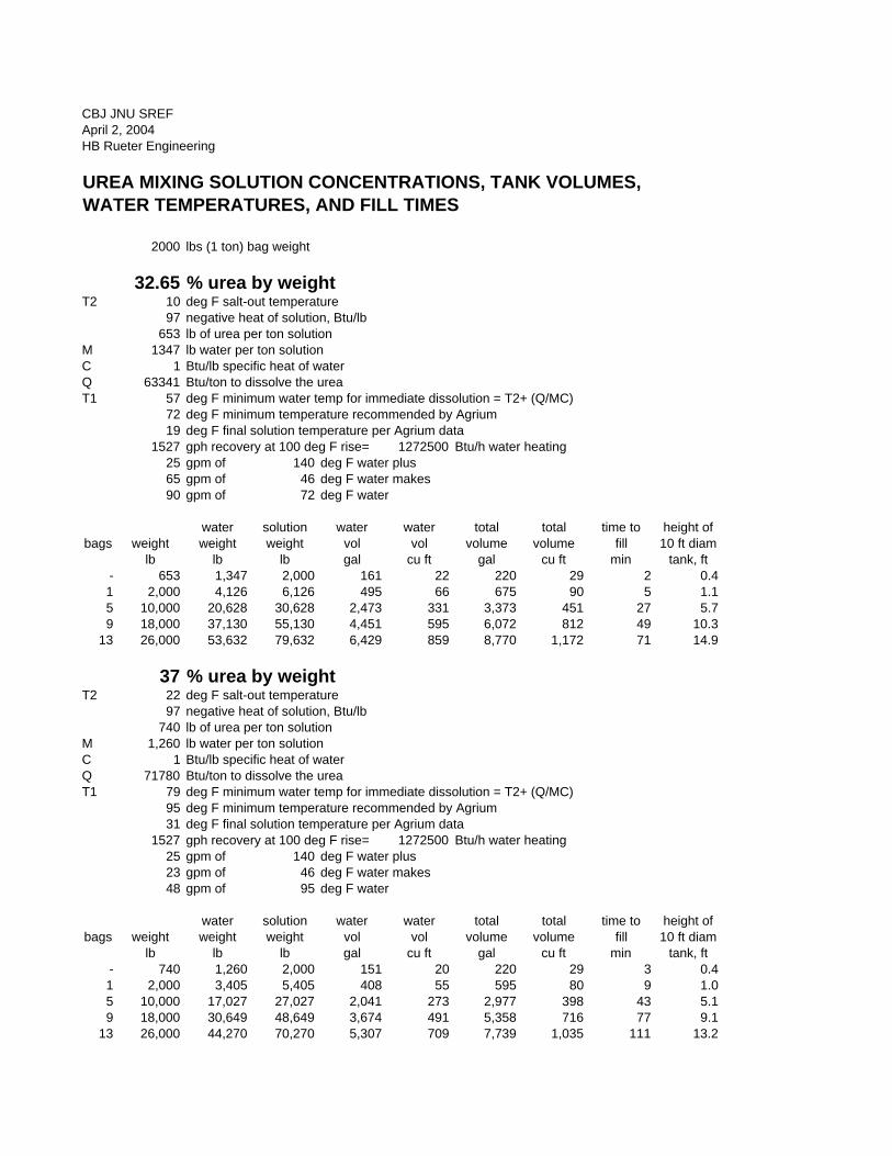
CBJ JNU SREFApril 2, 2004HB Rueter Engineering
UREA MIXING SOLUTION CONCENTRATIONS, TANK VOLUMES,WATER TEMPERATURES, AND FILL TIMES
2000 lbs (1 ton) bag weight
32.65 % urea by weightT2 10 deg F salt-out temperature
97 negative heat of solution, Btu/lb653 lb of urea per ton solution
M 1347 lb water per ton solutionC 1 Btu/lb specific heat of waterQ 63341 Btu/ton to dissolve the ureaT1 57 deg F minimum water temp for immediate dissolution = T2+ (Q/MC)
72 deg F minimum temperature recommended by Agrium19 deg F final solution temperature per Agrium data
1527 gph recovery at 100 deg F rise= 1272500 Btu/h water heating25 gpm of 140 deg F water plus65 gpm of 46 deg F water makes90 gpm of 72 deg F water
water solution water water total total time to height ofbags weight weight weight vol vol volume volume fill 10 ft diam
lb lb lb gal cu ft gal cu ft min tank, ft- 653 1,347 2,000 161 22 220 29 2 0.41 2,000 4,126 6,126 495 66 675 90 5 1.15 10,000 20,628 30,628 2,473 331 3,373 451 27 5.79 18,000 37,130 55,130 4,451 595 6,072 812 49 10.3
13 26,000 53,632 79,632 6,429 859 8,770 1,172 71 14.9
37 % urea by weightT2 22 deg F salt-out temperature
97 negative heat of solution, Btu/lb740 lb of urea per ton solution
M 1,260 lb water per ton solutionC 1 Btu/lb specific heat of waterQ 71780 Btu/ton to dissolve the ureaT1 79 deg F minimum water temp for immediate dissolution = T2+ (Q/MC)
95 deg F minimum temperature recommended by Agrium31 deg F final solution temperature per Agrium data
1527 gph recovery at 100 deg F rise= 1272500 Btu/h water heating25 gpm of 140 deg F water plus23 gpm of 46 deg F water makes48 gpm of 95 deg F water
water solution water water total total time to height ofbags weight weight weight vol vol volume volume fill 10 ft diam
lb lb lb gal cu ft gal cu ft min tank, ft- 740 1,260 2,000 151 20 220 29 3 0.41 2,000 3,405 5,405 408 55 595 80 9 1.05 10,000 17,027 27,027 2,041 273 2,977 398 43 5.19 18,000 30,649 48,649 3,674 491 5,358 716 77 9.1
13 26,000 44,270 70,270 5,307 709 7,739 1,035 111 13.2
Juneau International Airport Snow Removal Equipment Facility
810900 Client Meeting 2:30 PM, January 26, 2004
Page 1 of 3 USKH, Inc.
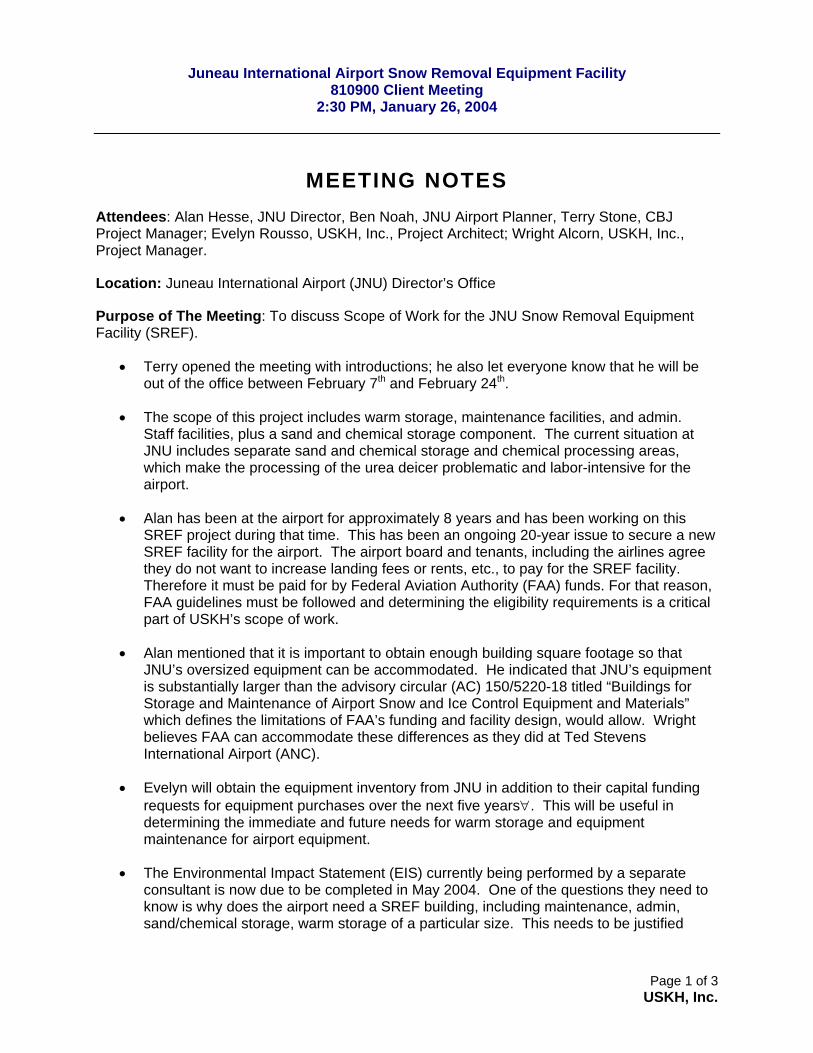
MEETING NOTES Attendees: Alan Hesse, JNU Director, Ben Noah, JNU Airport Planner, Terry Stone, CBJ Project Manager; Evelyn Rousso, USKH, Inc., Project Architect; Wright Alcorn, USKH, Inc., Project Manager.
Location: Juneau International Airport (JNU) Director’s Office
Purpose of The Meeting: To discuss Scope of Work for the JNU Snow Removal Equipment Facility (SREF).
• Terry opened the meeting with introductions; he also let everyone know that he will be out of the office between February 7th and February 24th.
• The scope of this project includes warm storage, maintenance facilities, and admin. Staff facilities, plus a sand and chemical storage component. The current situation at JNU includes separate sand and chemical storage and chemical processing areas, which make the processing of the urea deicer problematic and labor-intensive for the airport.
• Alan has been at the airport for approximately 8 years and has been working on this SREF project during that time. This has been an ongoing 20-year issue to secure a new SREF facility for the airport. The airport board and tenants, including the airlines agree they do not want to increase landing fees or rents, etc., to pay for the SREF facility. Therefore it must be paid for by Federal Aviation Authority (FAA) funds. For that reason, FAA guidelines must be followed and determining the eligibility requirements is a critical part of USKH’s scope of work.
• Alan mentioned that it is important to obtain enough building square footage so that JNU’s oversized equipment can be accommodated. He indicated that JNU’s equipment is substantially larger than the advisory circular (AC) 150/5220-18 titled “Buildings for Storage and Maintenance of Airport Snow and Ice Control Equipment and Materials” which defines the limitations of FAA’s funding and facility design, would allow. Wright believes FAA can accommodate these differences as they did at Ted Stevens International Airport (ANC).
• Evelyn will obtain the equipment inventory from JNU in addition to their capital funding requests for equipment purchases over the next five years∀. This will be useful in determining the immediate and future needs for warm storage and equipment maintenance for airport equipment.
• The Environmental Impact Statement (EIS) currently being performed by a separate consultant is now due to be completed in May 2004. One of the questions they need to know is why does the airport need a SREF building, including maintenance, admin, sand/chemical storage, warm storage of a particular size. This needs to be justified
Juneau International Airport Snow Removal Equipment Facility
810900 Client Meeting 2:30 PM, January 26, 2004
Page 2 of 3 USKH, Inc.
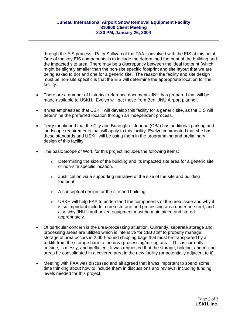
through the EIS process. Patty Sullivan of the FAA is involved with the EIS at this point. One of the key EIS components is to include the determined footprint of the building and the impacted site area. There may be a discrepancy between the ideal footprint (which might be slightly smaller than the non-site specific footprint and site layout that we are being asked to do) and one for a generic site. The reason the facility and site design must be non-site specific is that the EIS will determine the appropriate location for the facility.
• There are a number of historical reference documents JNU has prepared that will be made available to USKH. Evelyn will get those from Ben, JNU Airport planner.
• It was emphasized that USKH will develop this facility for a generic site, as the EIS will determine the preferred location through an independent process.
• Terry mentioned that the City and Borough of Juneau (CBJ) has additional parking and landscape requirements that will apply to this facility. Evelyn commented that she has these standards and USKH will be using them in the programming and preliminary design of this facility.
• The basic Scope of Work for this project includes the following items;
o Determining the size of the building and its impacted site area for a generic site or non-site specific location.
o Justification via a supporting narrative of the size of the site and building footprint.
o A conceptual design for the site and building.
o USKH will help FAA to understand the components of the urea issue and why it is so important include a urea storage and processing area under one roof, and also why JNU’s authorized equipment must be maintained and stored appropriately.
• Of particular concern is the urea-processing situation. Currently, separate storage and processing areas are utilized which is intensive for CBJ staff to properly manage: storage of urea occurs in 2,000-pound shipping bags that must be transported by a forklift from the storage barn to the urea processing/mixing area. This is currently outside, is messy, and inefficient. It was requested that the storage, holding, and mixing areas be consolidated in a covered area in the new facility (or potentially adjacent to it).
• Meeting with FAA was discussed and all agreed that it was important to spend some time thinking about how to include them in discussions and reviews, including funding levels needed for this project.
Juneau International Airport Snow Removal Equipment Facility
810900 Client Meeting 2:30 PM, January 26, 2004
Page 3 of 3 USKH, Inc.
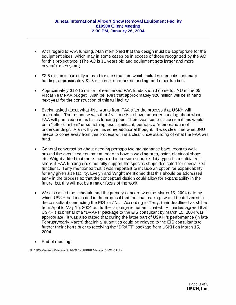
• With regard to FAA funding, Alan mentioned that the design must be appropriate for the equipment sizes, which may in some cases be in excess of those recognized by the AC for this project type. (The AC is 11 years old and equipment gets larger and more powerful each year.)
• $3.5 million is currently in hand for construction, which includes some discretionary funding, approximately $1.5 million of earmarked funding, and other funding.
• Approximately $12-15 million of earmarked FAA funds should come to JNU in the 05 Fiscal Year FAA budget. Alan believes that approximately $20 million will be in hand next year for the construction of this full facility.
• Evelyn asked about what JNU wants from FAA after the process that USKH will undertake. The response was that JNU needs to have an understanding about what FAA will participate in as far as funding goes. There was some discussion if this would be a “letter of intent” or something less significant, perhaps a “memorandum of understanding”. Alan will give this some additional thought. It was clear that what JNU needs to come away from this process with is a clear understanding of what the FAA will fund.
• General conversation about needing perhaps two maintenance bays, room to walk around the oversized equipment, need to have a welding area, paint, electrical shops, etc. Wright added that there may need to be some double-duty type of consolidated shops if FAA funding does not fully support the specific shops dedicated for specialized functions. Terry mentioned that it was important to include an option for expandability for any given size facility. Evelyn and Wright mentioned that this should be addressed early in the process so that the conceptual design could allow for expandability in the future, but this will not be a major focus of the work.
• We discussed the schedule and the primary concern was the March 15, 2004 date by which USKH had indicated in the proposal that the final package would be delivered to the consultant conducting the EIS for JNU. According to Terry, their deadline has shifted from April to May 15, 2004 but further slippage is not anticipated. All parties agreed that USKH’s submittal of a “DRAFT” package to the EIS consultant by March 15, 2004 was appropriate. It was also stated that during the latter part of USKH ‘s performance (in late February/early March) that initial quantities could be relayed to the EIS consultants to further their efforts prior to receiving the “DRAFT” package from USKH on March 15, 2004.
• End of meeting.
I:\810900\Meetings\Minutes\810900 JNUSREB Minutes 01-26-04.doc
Juneau International Airport (JNU) Snow Removal Equipment Facility
810900 Site Visit and Interview Notes February 10, 2004
Page 1 of 5 USKH, Inc.
SITE VISIT AND INTERVIEW NOTES Met With: Alan Heese, JNU Manager, Jerry Mahle, JNU Airfield Ops./Maintenance Supervisor, Ben Mello, JNU Airport Planner, Evelyn Rousso, USKH, Inc (USKH)., Design Leader; Wright Alcorn, USKH, Inc., Project Manager.
Purpose of The Meeting: To get oriented with the attributes of the airport specifically related to the activities and operations inventory and facilities for the Airport Maintenance Group, as well as understand the airport administrations concerns relative to the JNU Snow Removal Equipment Facility (SREF).
• USKH was selected for this project after a request for proposal (RFP) process. Others, selected prior to USKH, that are assisting the airport with environmental permitting and surveying activities are; Carson Dorn with assistance from HDR Alaska, Anne Leggett, P.E. from HDR is their lead.
• The firm of SWCA has been contracted separately through the City and Borough of Juneau (CBJ) to complete the Environmental Impact Statement (EIS). Carson Dorn is completing the permitting phase.
• The project includes the SREF building, which has maintenance and administration components, as well as a sand shed, and space for exterior storage and infrastructure (fueling, urea processing, etc.).
• During the meeting and subsequent site inspection and facility walk through, USKH and airport members of the team largely completed the 10-page questionnaire USKH provided at the outset of this meeting. Jerry Mahle will complete the remaining portions and send to USKH.
• USKH’s goal for this project is twofold:
o To support the ongoing EIS and permitting effort by determining the appropriate size of the facility in terms of the square footage (sf); and to determine the appropriate acreage for a theoretical facility to be located somewhere on the airport grounds.
o To assist the airport with funding for this project in terms of Federal Aviation Administration (FAA) allowable support.
• We discussed ground rules and operations during this project and may include the following:
o In Terry Stone’s absence (Terry is the CBJ’s Project Manager), all correspondence will go through Airport Planner, Ben Mello so that the airport is kept in the loop on any communications or correspondence.
• Schedule
Juneau International Airport (JNU) Snow Removal Equipment Facility
810900 Site Visit and Interview Notes February 10, 2004
Page 2 of 5 USKH, Inc.
o The assembled team confirmed that the March 15, 2004 date for USKH draft deliverables is still valid. Wright Alcorn asked that if the EIS project schedule slips, then USKH be given fair warning so that our aggressive schedule can be adjusted similarly. It was also mentioned that between now and March 15, USKH will engage the other members of the airport’s team working on the permitting and the EIS so that at the March 15 date there would be no surprises.
• Maintenance Supervisor, Jerry Mahle has been at the airport since approximately 1978, and Manager Heese for approximately 8 years. Manager Heese started as the airport planner.
• This project seeks complete FAA funding for the entire project scope. While it is understood that FAA must support Warm Storage and Maintenance facilities for all FAA funded equipment, i.e., trucks, graders, sanders, etc., there are additional AIP funded equipment at the airport. It is critical to justify to the FAA the need for appropriate storage and maintenance square footage for this facility. It is of significant concern that Juneau’s Airport Board not be the first stop for additional funding should complete FAA funding not be available.
o The FAA may fund more than one maintenance bay for example, however, the need in Juneau for a separate maintenance bay is critical. Due to the special conditions there, the drivers of the equipment perform routine preventive maintenance (PM) themselves. USKH will explain how critical an additional bay is in maintaining readiness. The extensive equipment the SREF staff maintains, includes fire-fighting equipment for the Juneau Airport Rescue and Fire Fighting (ARFF) station nearby.
o The funding mechanisms available to the airport include the PFC (Passenger Facility Charge) program, the AIP (Airport Improvement Program), or charges to airport tenants.
• The types of activities the maintenance group and airport maintenance staff performs include all large equipment maintenance and a number of associated and miscellaneous tasks.
o Float construction for the floatplane pond; this includes construction of some wooden floats.
o Miscellaneous carpentry associated with temporary wooden scaffolding, stairs, etc., and from time to time support of terminal maintenance and operations. In fact, the terminal maintenance shops’ carpentry facility is in the airfield maintenance groups’ area.
o The group also maintains radios and communications equipment for their staff; this is limited however, to simple exchange of parts. Any complex repairs are outsourced.
Juneau International Airport (JNU) Snow Removal Equipment Facility
810900 Site Visit and Interview Notes February 10, 2004
Page 3 of 5 USKH, Inc.
o Some of the equipment the group has, includes a lathe, sandblaster for parts (these currently are in separate areas) associated compressors, Hotsy’s, and a number of small and portable types of equipment.
o The staff performs wildlife maintenance as required to flush out birds and other animals that pose a hazard to aviation in the vicinity of the runway.
o The maintenance staff respond to hazardous materials spills either on the airfield or the float pond.
o Exterior stored items include the following:
500-CY D-1 gravel (approximately 40 by 40-foot exterior stockpile) The sand storage, which is approximately 5,000 CY. Large number of snow plow blades and buckets; this includes 30-foot-
long “bull” blades.
o Covered cold storage includes
Used oil (not normally)
4-Connex configuration where Spill response equipment, small power tools (trimmers, lawn mowers, etc.), and tractor and tractor attachments are kept.
Space for brush boxes for the runway brooms (approximately 4’ by 4’ by 2’) Total 54.
o Interior warm storage includes: Approximately 100 bags of cold asphalt patch which must be kept warm. Used oil for burning in Used Oil Furnace.
o Miscellaneous exterior equipment:
Urea tanks include a 10, 000-, 12,000-, and an 8,000-gallon horizontally installed cylindrical tanks.
Fueling Operation
o Emergency generators include:
Emergency generator for runway lights. This is an older unit (perhaps 30 years old and the airport would like a new one)
A emergency generator to power the new facility. The existing facility has a new emergency generator but it is not known if this is adequate to power the new and potentially larger maintenance facility.
o Airport chemicals include:
Juneau International Airport (JNU) Snow Removal Equipment Facility
810900 Site Visit and Interview Notes February 10, 2004
Page 4 of 5 USKH, Inc.
CG90 – 2000 pound bags. Stored unheated, but staged in warm truck ready to go.
Urea in pellet form. This arrives at the airport in 2,000-pound bags that is mixed in a vat over a 3-day period for storage in three urea tanks for later distribution by a truck.
There was some discussion relative to the urea as to different shipping and storage mechanisms. USKH agreed to get in touch with two of the potential vendors for this product to understand if shipping options exist. However, after additional discussion it was determined that the bag form may represent the airport’s best opportunity to control the quality and minimize the extra handling of the urea. This is in consideration of the joint purchase and shipping agreement has with CBJ.
o Equipment that must be stored inside:
The CG90 truck must be kept warm and dry. The urea truck, which requires 3-phase 208/240V. The electrical truck must be kept adjacent to the electrical supply room.
o Other equipment that this group has includes.
A “gas boy” to control and monitor both gas and diesel operations. Computer inter-connected with airport lighting systems.
• The existing weather station on the top of the maintenance facility will be decommissioned and a new one will be installed on the terminal. A weather station is not anticipated for the new facility.
• The maintenance staff performs all low-voltage and airport lighting duties. All high-voltage work is subcontracted out. Essentially they do all electrical work outside of the terminal unless it is high-voltage.
• The existing facility has an electrical vault associated with it, which serves the airport lighting. Of airport concern is the intertie between a computer located in this area and one in the existing maintenance facility. When the new building is constructed elsewhere on the airport, this vault will not be relocated but one of the computers must be (see above).
• Much discussion and comment was obtained on the interview questionnaire, which will be included as an attachment to this document.
• Upon completing the airfield and maintenance facility tour, Evelyn and Wright returned and met with Ben Mello and Director Heese to discuss our findings and the next steps.
o Wright raised the issue of the break/training room in the proposed building as perhaps also serving as an emergency-response type facility for the airport. A potential exists for this to be attractive to the FAA, as it would provide a function
Juneau International Airport (JNU) Snow Removal Equipment Facility
810900 Site Visit and Interview Notes February 10, 2004
Page 5 of 5 USKH, Inc.
to the airport that does not currently exist. Further discussion on this will need to occur.
o Discussed the other federal representatives at the airport:
Wildlife Management – currently Bill Weymouth of USDA has an office located in the maintenance facility; the maintenance staff is responsible for controlling wildlife and storing the firearms associated with the program
NOAA rents space in the hangar used for chemical and sand storage.
o The maintenance of the ARFF vehicles is conducted by the maintenance group at the airport. Wright will research the Advisory Circulars (ACs) to find out if ARFFs are required to have their own maintenance capability. Director Heese will contact the former ARFF Chief and ask about the funding for the Juneau ARFF facility as to if funding for a maintenance bay was originally obtained. The thought was there might be additional funding available for this facility due to the maintenance staff’s ongoing responsibility to maintain the ARFF equipment.
o The work session in Juneau will be March 8. This will include a discussion of all the programming that USKH will have done and will be an all-day session.
o Relative to the status of the ongoing EIS, a meeting will be held next week with Patty Sullivan of FAA and Ken Wallace representing SWCA. USKH will participate in that conversation.
o Other players in this project include Steve Powell, FAA’s new SRE manager. It is thought that this is mostly a compliance position. Also, Jim Loman, FAA’s planner and funding point person, and Pat Oine, FAA’s engineer. Patty Sullivan is the FAA permitting lead.
• End of meeting.
I:\810900\Meetings\Minutes\810900 JNUSREB Minutes 01-26-04.doc
Juneau International Airport Snow Removal Equipment Facility 810900 Work Session
March 10, 2004
Page 1 of 6 USKH, Inc.
Meeting with Jim, Jerry, Allan, Terry, Evelyn & Wright at Juneau International Airport
1. Introduction by Wright, overview of day and agenda. 2. Recent history and near future:
Χ No contact with Ken Wallace since conference call in February. Χ Contacted Jim Lowman at FAA re: space justification, requested
opportunity to review USKH documents. Χ USKH will send SWCA (Ken Wallace) draft info when available.
USKH will have JNU admin review/approach concepts first. Χ FAA would also like to review draft USKH documents: USKH to
obtain review/approval from JNU first. Anticipate week of March 20 for JNU review, first week of April for FAA.
Allan H. later clarified that perhaps formal FAA review not needed. Wright suggested that an over the shoulder review w/ FAA was perhaps appropriate. Allan agreed. Terry thought that Draft Environmental Impact Statement (DEIS) is to be submitted in early June, 2004.
3. Confirmed that USKH’s mission is to support EIS objectives: Χ Develop realistic footprint for building and site. Χ Consider future equipment. Χ The full building (ultimate size) may not be constructed now, but the
final size (potential) should be used for determining size of site impact.
4. Allan changed scope slightly in that he said we should design a facility that is what is need ultimately (which might be larger than what FAA could support) rather than scaling it back to what we believe FAA will support.
5. FAA did an earlier review of similar JNU project (Ben Mello’s predecessor) that was marked-up heavily. The rationale for the requested size was not well supported.
6. Discussion of USKH documents and activities planned for today’s workshop:
A. Programming space matrix Χ Several area adjustments must be made (and others
that are brought to our attention today) – Wright marked up spreadsheet for corrections. Example: bags of urea and CG-90 are actually 5’x5’; not 4’x4’; increasing storage area requirements.
Χ Several functional/space list changes also made. B. Programming of exterior spaces C. Equipment matrix
Juneau International Airport Snow Removal Equipment Facility 810900 Work Session
March 10, 2004
Page 2 of 6 USKH, Inc.
Χ Reviewed inside/outside, FAA-funded equipment and AIP vs. PFC funded equipment. Basically, if equipment was approved by FAA (PFC or AIP $) then Allan feels that FAA will support warm storage for it. Wright to verify with Pat Oine and/or Jim Lowman @ FAA.
D. Meeting minutes from Feb. 10, 2004 need answers to a few lingering questions.
7. Programming Space Matrix Urea, Warm Storage, and Maintenance Facility (shops) discussion.
A. Urea and CG-90 • Adjust size of storage areas. • Size of bags 5’x 5’ • Need circulation space. • Processing methodology for urea:
1. High mixing tank is a safety concern (bags must be opened and emptied into tank.)
2. Consider mounting at floor level (with top open and covered with grate. Put stainless steel tank in concrete vessel; make large enough to allow access to pumps, etc. This allows building to be shorter.
3. Storage tank location: • Concern about having to heat water for
mixing but than losing that heat if tanks (currently 8k, 10k, and 12k gallon capacities) are located outside.
• After much discussion, it was decided that a single 12k gallon would be located inside the Urea/CG-90 building, and heated. Only one tank should be needed due to faster urea solution cycle times with new arrangement.
• Urea Storage tank would be heated to x 70°F
• Boiler to heat Urea Storage solution mixing tank will be of significant size. This equipment could be used to supply low-grade heat to warm storage (radiant slab)
• Truck fill (for urea) should be in a contained area, if possible. This would
Juneau International Airport Snow Removal Equipment Facility 810900 Work Session
March 10, 2004
Page 3 of 6 USKH, Inc.
prevent urea from being spread over the site if spilled during filling operations.
• CG-90 Processing • CG-90 truck will be filled outside, under a “carport”
per new design. The distribution vehicle must be kept inside and heated when not in use.
• Revised the floor plan to reflect user concerns and efficiency of loading, handling, and distribution.
• Allan is interested in an energy analysis on interior (heated) tank location for urea versus an exterior location, additional tank, and truck heating costs. Terry said to hold off for now.
• If urea tank is buried, is water table a concern? 1. Yes, must be ballasted. 2. Will provide concrete “cupholder” with mudslab
and membrane to resist saltwater intrusion. • Benefits of floor level urea processing tank location
include: fewer accidents reaching top, fewer problems with urea auger, and faster, more efficient staff operations. Also, building can be shorter (not as tall, due to height of bag required.) Access to pumps (in “cupholder”) must be maintained.
B. Painting and sand blasting • Sand blasting occurs on large items (like blades). Jerry
had wanted a separate paint bay. Wright suggested that for layout items an area could be draped with containment. Could be used as a maintenance bay in summer.
• Use silica sand media. C. Parts Inventory
• OK on mezzanine. • Put broom cores in Urea/ CG-90 building.
D. Tools • Need to include space for lathe, drill press, and
sandblast. E. Lube Products
• Increased the size of room due to (9) active drums (55gallon) in use at one time. Also one spare drum for each product needed on hand. • Storage in open area (Work bay) could be a code problem. Containment (in floor) is a must. (Reminder: verify fire-rated room requirements.)
Juneau International Airport Snow Removal Equipment Facility 810900 Work Session
March 10, 2004
Page 4 of 6 USKH, Inc.
F. Sign Shop/ Carpentry • Adjust size larger for carpentry. • Painting can be elsewhere (like in a Work bay for larger
items) G. Maintenance Bays (All Three)
• Overhead doors (OHD) should be 26’ wide • Showing 32’wide bays (to allow for safe work area
around large equipment. • Bridge crane should cover all bays. • Mezzanine access.
H. Toilet Rooms • The Women’s Toilet Room to be combined (currently no female employees) with locker room. Reminder: check to see if, for the given occupant load, this building requires separate toilet facilities. • Men’s combined with lockers too. (13 lockers total)
I. “Fueling Equipment” recommended to be located in “system’s room”. This room will contain the “Gas Boy” computer, runway lighting computer, and records.
J. Mezzanines will not be in square footage calculations. K. Tire Storage: ARFF vehicle tires, loaders, etc. This is OK
on Mezzanine. 7. Programming Matrix Exterior Spaces
A. Parking: Employee and visitor parking will be located outside of the airport fence. Parking for airport owned trucks and vehicles will be provided inside the fence.
B. Exterior Storage: Currently the maintenance department stores materials and vehicles in a variety of locations on the airfield. This site will provide an opportunity to consolidate their equipment.
C. Snow Storage: Snow storage should be designated as a linear strip on one side of the site. Experience has shown that this should be the equivalent of 5-10% of the total paved area.
D. Vegetative Cover: There are concerns about the CBJ zoning requirement for vegetative cover, as it will attract birds and wildlife. The airport can request a, however this should be included on the site plan.
E. Fueling Station: The fueling station needs to accommodate vehicles with sidesaddle tanks. The fire station and ARFF use the fueling station at the current Maintenance shop. Access must be provided for the large ladder truck.
Juneau International Airport Snow Removal Equipment Facility 810900 Work Session
March 10, 2004
Page 5 of 6 USKH, Inc.
F. Loading Zone: Each fall urea and cg-90 is delivered in four containers, which are unloaded over the course of several weeks. There is a ramp that they use for this task. The site should contain a location for the containers in the vicinity of the chemical storage building. A separate unloading dock is not required.
G. Urea Storage: All processing tanks will be inside, however the a station for filling the urea truck can be outside. It should be adjacent to the urea processing area.
H. Sand Storage: There are concerns about how to best convey sand to the sand pile, and more importantly how to load sand trucks without exposing the sand to contamination and the weather. We should avoid hoppers or other mechanical devices if they are to be are exposed to the weather. A square building is preferred to a cone shaped building so there is some maneuvering capability within the volume of the building.
I. Traffic flow should be organized so that snow removal vehicles have direct access to the runway.
J. Although a loop road around the site is desirable, the number of electronic gates for access through the fence should be limited.
9. Programming Equipment Matrix A. Turning “radius” on sheets is actually “Diameter” B. Added “Friction Tester” Vehicle as #29. This is a Chevy
Blazer with a trailer. Estimate length at 24’ x 12’ wide. Must be stored inside.
10. Allan wants site and building to be environmentally friendly A. Include spaces for exterior dumpster (near fence) B. Hazardous waste accumulation point (this is a 8’ x 6’
heated metal shed.) C. Control Runoff. Discussion about “stuff” that falls off
vehicles. If vehicles are washed in an environment where stuff falls off, subsequent deposits should be incidental. Suggest use of bio swales around parking area (could be combined with CBJ Zoning requirements.)
11. Warm Storage A. Wash Bay to be adjusted to this, with hose bibs inside and
oil/water separator. Discussion about excessive humidity from washing and needed separation.
B. Configuration • Drive through good use of space. • Will use angled configuration.
Juneau International Airport Snow Removal Equipment Facility 810900 Work Session
March 10, 2004
Page 6 of 6 USKH, Inc.
• Put exterior overhang on one wall (shed roof) for storage of equipment (connex’s, etc.) outside.
12. Allan is less concerned about FAA Funding, may have to go to Airport Board for some funding. USKH will still try to get FAA to be supportive where possible. Other: Allan is concerned about Operations and Maintenance (O&M) costs in following areas:
• Urea operations • Heating. Etc. • Use of used oil in furnace; they generate 1,000 gallons
annually. Other: The narrative USKH produces should include discussion of why certain decisions are made:
• Delivery limitations for urea/CG-90 • Stockpiling of broom cores • Relationship between horizontal surfaces and
equipment (though Allan said this is not so important anymore)
• Etc. End of meeting