cisco trustsec how-to guide: monitor mode trustsec version number (for example, trustsec version...
TRANSCRIPT

Cisco TrustSec How-To Guide: Monitor Mode
For Comments, please email: [email protected]
Current Document Version: 3.0
August 27, 2012

HowTo-21-Monitor_Mode_Deployment_Guide 2
Table of Contents
Table of Contents ........................................................................................................................... 2
Introduction ................................................................................................................................... 3
What Is the TrustSec System? .......................................................................................................................................................................................................................................... 3 About the TrustSec How-To Guides ............................................................................................................................................................................................................................... 3
What does it mean to be ‘TrustSec Certified’? .................................................................................................................................................................... 4
Monitor Mode ............................................................................................................................... 5
Overview of Monitor Mode ................................................................................................................................................................................................................................................ 5 Understanding the Flow Before Deployment ...................................................................................................................................................................... 5
ISE Deployment ...................................................................................................................................................................................................................................................................... 6 Deployment Strategy ........................................................................................................................................................................................................... 6
Configure Authentication .................................................................................................................................................................................................... 7
Authorization Configuration .......................................................................................................................................................................................................................................... 11 Begin Authorization Configuration ................................................................................................................................................................................... 11
Monitoring in Monitor Mode ............................................................................................................................................................................................ 17
Appendix A: References .............................................................................................................. 18
Cisco TrustSec System: ..................................................................................................................................................................................................................................................... 18 Device Configuration Guides: ........................................................................................................................................................................................................................................ 18

HowTo-21-Monitor_Mode_Deployment_Guide 3
Introduction
What Is the TrustSec System?
Cisco TrustSec®, a core component of the Cisco SecureX Architecture™, is an intelligent access control solution. TrustSec
mitigates security risks by providing comprehensive visibility into who and what is connecting across the entire network
infrastructure, and exceptional control over what and where they can go.
TrustSec builds on your existing identity-aware access layer infrastructure (switches, wireless controllers, and so on). The
solution and all the components within the solution are thoroughly vetted and rigorously tested as an integrated system.
In addition to combining standards-based identity and enforcement models, such as IEEE 802.1X and VLAN control, the
TrustSec system it also includes advanced identity and enforcement capabilities such as flexible authentication,
Downloadable Access Control Lists (dACLs), Security Group Tagging (SGT), device profiling, posture assessments, and
more.
Figure 1: TrustSec Architecture Overview
About the TrustSec How-To Guides
The TrustSec team is producing this series of How-To documents to describe best practices for TrustSec deployments. The
documents in the series build on one another and guide the reader through a successful implementation of the TrustSec
system. You can use these documents to follow the prescribed path to deploy the entire system, or simply pick the single
use-case that meets your specific need.
Each guide is this series comes with a subway-style “You Are Here” map to help you identify the stage the document
addresses and pinpoint where you are in the TrustSec deployment process (Figure 2).
Figure 2: How-To Guide Navigation Map
SXP
Data Center
Wireless user
Campus Network Wired
user
Egress Enforcement
MACsec
Profiler
Posture
Guest Services
Security
Gro
up Tag
RADIUS
Ingress Enforcement
Ingress Enforcement
Security
Group Tag

HowTo-21-Monitor_Mode_Deployment_Guide 4
What does it mean to be ‘TrustSec Certified’?
Each TrustSec version number (for example, TrustSec Version 2.0, Version 2.1, and so on) is a certified design or
architecture. All the technology making up the architecture has undergone thorough architectural design development and
lab testing. For a How-To Guide to be marked “TrustSec certified,” all the elements discussed in the document must meet
the following criteria:
Products incorporated in the design must be generally available.
Deployment, operation, and management of components within the system must exhibit repeatable processes.
All configurations and products used in the design must have been fully tested as an integrated solution.
Many features may exist that could benefit your deployment, but if they were not part of the tested solution, they will not be
marked as “TrustSec “certified”. The TrustSec team strives to provide regular updates to these documents that will include
new features as they become available, and are integrated into the TrustSec test plans, pilot deployments, and system
revisions. (i.e., TrustSec 2.2 certification).
Additionally, many features and scenarios have been tested, but are not considered a best practice, and therefore are not
included in these documents. As an example, certain IEEE 802.1X timers and local web authentication features are not
included.
Note: Within this document, we describe the recommended method of deployment, and a few different options depending on the level of security needed in your environment. These methods are examples and step-by-step instructions for TrustSec deployment as prescribed by Cisco best practices to help ensure a successful project deployment.

HowTo-21-Monitor_Mode_Deployment_Guide 5
Monitor Mode
Overview of Monitor Mode
Monitor Mode allows organizations to enable authentication across the wired infrastructure, without affecting wired users or
devices. It can be thought of as an “audit mode.” With the help of logging data for validation, administrators use Monitor
Mode to help ensure that all devices are authenticating correctly, either with 802.1X or MAC Authentication Bypass. If a
device is misconfigured or is missing an 802.1X supplicant, access will not be denied and simply logged. When deploying
Monitor Mode, most organizations are surprised at what devices they find connected to the network that they were unaware
of previously.
Wireless environments with 802.1X are binary (just like 802.1X was designed to be), so when users are unable to
authenticate, they simply do not get access to the wireless network. Most users can accept this behavior and are willing to
find a location with a physical network connection (a wired connection) instead. Although end users are mostly willing to
accept an inability to join a wireless environment, they are much less understanding when faced with a lack of access to a
wired network port.
Note: It is not possible to implement Monitor Mode with wireless networks. Therefore, we will introduce wireless in the Low-Impact Mode phase.
Monitor Mode is a process, not just a command on a switch. The process uses a combination of RADIUS accounting packets
and Open Authentication, and Multi-Auth features on your Cisco infrastructure, as well as device profiling, to give the
administrator visibility into who and what is connecting to the network, and from where. If a device should be
authenticating, but cannot because of a misconfiguration of sorts, the administrator will know and can correct it without
denying network access to the user.
This How-To Guide covers wired access in a campus and in a remote office (Figure 3). As discussed previously, there is no
concept of Monitor Mode with wireless access; wireless access will not be mentioned in this guide.
Figure 3 - Wired Scenarios in the Campus and Remote Office
Understanding the Flow Before Deployment
Before examining the Cisco® Identity Services Engine (ISE) default configuration or configuring anything new in the Cisco
ISE, it is critical that you have a solid understanding of the functions of network access and the network access processing
flow.
RADIUS-controlled network access follows a traditional authentication, authorization, and accounting (AAA) model.
An authentication is, simply put, verifying valid credentials. That’s all. An authentication could be verifying a client’s
certificate validity, or checking for a valid username/password combination. However, authentication does not provide any
access by itself.
Authorization is determining the level of access to provide an authenticated user or device. It is where the bulk of the work
occurs for controlling network access.
The Cisco ISE Graphical User Interface logic separates out the authentication and authorization policies. The authentication
policy will dictate what identity store to check based on the incoming authentication request. For example, an authentication
request coming from a VPN may be configured to check a one-time password (OTP) server to validate credentials.
Meanwhile, using the same Cisco ISE installation, an authentication request from a Cisco Wireless LAN Controller may
Ingress Enforcement
Cisco®
Catalyst® Switch
Wireless user
Wired user
Ingress Enforcement
Cisco®
Wireless Controller
Campus
Campus Network
Ingress Enforcement
Cisco® ISR w/ Ether-Switch
Wired user
Remote Office
Wired user
Remote Office
Cisco®
Catalyst® Switch
Ingress Enforcement

HowTo-21-Monitor_Mode_Deployment_Guide 6
result in validating the credentials with Active Directory. Cisco ISE provides a very powerful and flexible authentication
policy.
As Figure 4 illustrates, the authentication policy compares the incoming protocol to the configured rules, selects the assigned
identity store, and then the authorization policy takes over from there.
Figure 4 Authentication Policy
ISE Deployment
Deployment Strategy
Monitor Mode is a deployment strategy that provides full access regardless of authentication state (Figure 5). When
authentication is configured on each applicable device, Cisco ISE will provide visibility into which devices are authenticating
successfully and which ones are not. This How-to Guide only covers the configuration for ISE. For switchport configuration,
please refer to TrustSec How-To Guide: Global Switch Configuration.
Figure 5 Monitor Mode Port Behavior
Authentication Policy
Protocols Selection
… Identity Selection
Authorization Policy
Identity Selection
Identity Selection
Pre-AuthC
SWITCHPORT
KRB5 HTTP
TFTP DHCP
EAPoL Permit All
Post-AuthC
SWITCHPORT
KRB5 HTTP
TFTP DHCP
EAPoL
Permit All
Traffic always allowed

HowTo-21-Monitor_Mode_Deployment_Guide 7
Configure Authentication
Procedure 1 Examine the Default Cisco ISE Authentication Policy
Navigate to Policy Authentication (Figure 6).
Figure 6 Add an Authentication Policy
There are two preconfigured rules in the authentication policy, as well as a default rule. The Policy Rule table behaves like
an access list: it is processed from the top down, and the first match is the rule that is used.
The way an authentication request is matched to a rule-line is based on the conditions. To explain this further, we will
examine the first preconfigured rule, named MAB. This is a rule for MAC authentication bypass from switches.
Cisco ISE policy constructs are built in a logical IF-THEN format. Notice the IF just before the “picker” that says
Wired_MAB. This particular line is stating: “If RADIUS request is Wired_MAB, then allow the Default Network Protocols
to be used.” For instance:
IF Wired_MAB
THEN Allow the default protocols
ELSE Move to next Line in Authentication Policy Table
In Figure 7, notice the black drop-down triangle (outlined in Figure 7).
Click the triangle.
Figure 7: Add an Authentication Policy
Each rule in the Authentication Policy table has a second part to it. This is the line where the credential store is chosen. By
default, this preconfigured rule for MAC authentication bypass is configured to use the Internal Endpoints data store. The
Internal Endpoints data store is the database of known devices internal to ISE. This database can be populated manually or
dynamically.
Note: An example of manual population: The admin exports a list of known Cisco Unified IP Phone MAC addresses from the Cisco Unified Communications Manager interface, and imports that list into ISE.
An example of dynamic population: ISE profiling discovered this device via one or more of the profiling probes, and created the device entry in the Internal Endpoints data store.
So, the IF-THEN statement looks like this:
IF Wired_MAB
THEN Allow the default protocols
AND Check Credentials with the Internal Endpoints Data Store
ELSE Move to next Line in Authentication Policy Table

HowTo-21-Monitor_Mode_Deployment_Guide 8
Note: Wired_MAB is a prebuilt condition to match RADIUS attributes: service-type = call-check, and nas-port-type = ethernet.
Procedure 2 Enable Wireless Authentication
Navigate to Policy Authentication.
Expand the IF conditions for the Dot1X rule and choose Add Condition from Library (Figure 8).
Figure 8 Add an Authentication Policy
From the Select Condition drop-down menu, go to Compound Condition Wireless_802.1X (Figure 9).
Figure 9 Selecting the Conditions
Step 4 Ensure that the operator is specified as OR, not AND (Figure 10).
Figure 10 Choosing an Operator
Save the settings.
HowTo-21-Monitor_Mode_Deployment_Guide 9
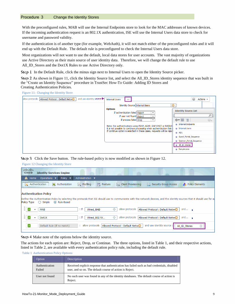
Procedure 3 Change the Identity Stores
With the preconfigured rules, MAB will use the Internal Endpoints store to look for the MAC addresses of known devices.
If the incoming authentication request is an 802.1X authentication, ISE will use the Internal Users data store to check for
username and password validity.
If the authentication is of another type (for example, WebAuth), it will not match either of the preconfigured rules and it will
end up with the Default Rule. The default rule is preconfigured to check the Internal Users data store.
Most organizations will not want to use the default, local data stores for user accounts. The vast majority of organizations
use Active Directory as their main source of user identity data. Therefore, we will change the default rule to use
All_ID_Stores and the Dot1X Rules to use Active Directory only.
In the Default Rule, click the minus sign next to Internal Users to open the Identity Source picker.
As shown in Figure 11, click the Identity Source list, and select the All_ID_Stores identity sequence that was built in
the “Create an Identity Sequence” procedure in TrustSec How-To Guide: Adding ID Stores and
Creating Authentication Policies.
Figure 11: Changing the Identity Store
Click the Save button. The rule-based policy is now modified as shown in Figure 12.
Figure 12 Changing the Identity Store
Make note of the options below the identity source.
The actions for each option are: Reject, Drop, or Continue. The three options, listed in Table 1, and their respective actions,
listed in Table 2, are available with every authentication policy rule, including the default rule.
Table 1 Authentication Policy Options
Option Description
Authentication
Failed
Received explicit response that authentication has failed such as bad credentials, disabled
user, and so on. The default course of action is Reject.
User not found No such user was found in any of the identity databases. The default course of action is
Reject.

HowTo-21-Monitor_Mode_Deployment_Guide 10
Process failed Unable to access the identity database or databases. The default course of action is Drop.
Table 2 Authentication Policy Actions
Action Description
Reject Sends a RADIUS ACCESS-REJECT response to the NAD.
Drop Drops the ACCESS-REQUEST, without sending a response.
Continue Proceed to the authorization policy.
Expand the Dot1X line, and repeat Steps 1 and 2 to change the identity source to be All_ID_Stores, as shown in
Figure 13.
Figure 13 Modify the Identity Source
Click Save.
Note: You can customize authentication rule extensively. In these examples, we have used the default network access as our allowed protocols. This allows the vast majority of authentication types, but using the defaults does not restrict access to a certain type of EAP method.
To configure a customized set of authentication protocols (such as EAP-TLS only), go to Policy Policy Elements Results Authentication Allowed Protocols.

HowTo-21-Monitor_Mode_Deployment_Guide 11
Authorization Configuration
Begin Authorization Configuration
Procedure 1 Examine the Default Cisco ISE Authorization Policy
As discussed previously, authentication is simply the validation of user credentials. All the enforcement and access control
occurs within the authorization phase of network access.
Navigate to Policy Authorization, and click Edit to update the rule (Figure 14).
Figure 14 Edit an Authorization Policy
There is one preconfigured rule in the authorization policy, plus the default rule. Just as in the authentication policy, the
Authorization Rule table behaves like an access list by default: it is processed from the top down, and the first match is the
rule that is used.
Note: The Authorization Table can match multiple rules, allowing for very complex authorization results. This topic is considered out of scope for this document.
Cisco Best Practice: Use the default: First Matched Rule Applies.
Just as in the authentication policy, the manner in which an authorization request is matched to a rule line is based on the
conditions. To explain this concept further, we will examine the preconfigured rule named Profiled Cisco IP Phones. As the
name implies, this rule is used to authorize Cisco Unified IP Phones that were identified in the profiling process.
Table 3: Authentication Policy
Option Description
Identity Groups Special groups that are manually or dynamically created, such as guest and Whitelist.
Other Conditions All other conditions, such as Group Membership.
Permissions Authorization profile result.
Cisco ISE policy constructs are built in a logical IF-THEN format. Examining this rule, we see that:
IF Device is member of ISE ID Group = Cisco-IP-Phone
AND (no other conditions in this line)
THEN Assign the Cisco_IP_Phone Authorization Profile
ELSE Move to next Line in Authentication Policy Table
View the details of the Cisco_IP_Phone authorization profile.
To see the details of the Cisco_IP_Phone authorization profile, hover the mouse cursor over the Permissions picker. The
Permission Details pop-up appears. Click the link for Cisco_IP_Phones (Figure 15).

HowTo-21-Monitor_Mode_Deployment_Guide 12
Figure 15: Edit an Authorization Policy
As shown in the Authorization Profile Details in Figure 16, Cisco_IP_Phones sends a RADIUS Access-Accept message,
sends a downloadable ACL (dACL) named PERMIT_ALL_TRAFFIC, and allows the device to join the Voice Domain
(voice VLAN).
Figure 16: Authorization Profile Details
As shown in Figure 17, an IP phone requires a special RADIUS attribute to be sent in the authorization result, which grants
the device permission to join the voice VLAN.
Figure 17 Multi-Domain Authentication (MDA)
SWITCHPORT
Data Domain
Voice Domain Authenticated
Authenticated
EAPoL EAPoL, MAC

HowTo-21-Monitor_Mode_Deployment_Guide 13
Procedure 2 Create a Whitelist for Endpoints
We will manually create a Whitelist identity group. This is a group that an administrator can add a device to in order to
permit it full access to the network. This permission is recommended only for special cases.
Navigate to Administration Identities Groups Endpoint Identity Groups.
Click Add (Figure 18).
Figure 18 Add an Identity Group
Name the new group Whitelist. Leave the Parent Group drop-down field blank (Figure 19).
Figure 19 New Endpoint Group
Click Submit.
Note: When troubleshooting or for special circumstances, a device can be added to this list, and it will be permitted access to the network.
To add a device to the Whitelist group, navigate to Administration Identities Endpoints, and click Add (Figure
20).
Figure 20 Add an Endpoint

HowTo-21-Monitor_Mode_Deployment_Guide 14
Add the device MAC address in format nn:nn:nn:nn:nn:nn, and select Whitelist from the Identity Group Assignment
drop-down menu (Figure 21).
Figure 21 New Endpoint
Note: If the device type is known (for example, Android), it may be selected from the Policy Assignment drop-down menu.
Procedure 3 Create an Authorization Profile for Whitelisted Devices
Navigate to Policy Policy Elements Results Authorization Authorization Profiles (Figure 22).
Figure 22 Add an Authorization Profile for Whitelisted Devices
Click Add.
Configure the new Authorization profile as described.
Name = Whitelist
Description = Authorization Profile for Whitelist
Access-Type = ACCESS_ACCEPT
-- Common Tasks
DACL Name = PERMIT_ALL_TRAFFIC

HowTo-21-Monitor_Mode_Deployment_Guide 15
Figure 23: New Authorization Profile
The attributes details are shown as in Figure 24.
Figure 24 Attribute Details
Click Submit.
Procedure 4 Create an Authorization Rule for Whitelisted Devices
Navigate to Policy Authorization.
Click Actions at the end of the IP-Phone Authorization rule (Figure 25).
Figure 25 Create an Authorization Policy for Whitelisted Devices
Select Insert New Rule Below.
Name the new rule Whitelist.
Click the plus sign next to Any in the Identity Group column (Figure 26).

HowTo-21-Monitor_Mode_Deployment_Guide 16
Figure 26 Choose the Identity Group
Select the Endpoint Identify Groups (Figure 27).
Figure 27 Endpoint Identity Groups
Select Whitelist Identity Group from the picker (Figure 28).
Figure 28 Whitelist identity Group
HowTo-21-Monitor_Mode_Deployment_Guide 17
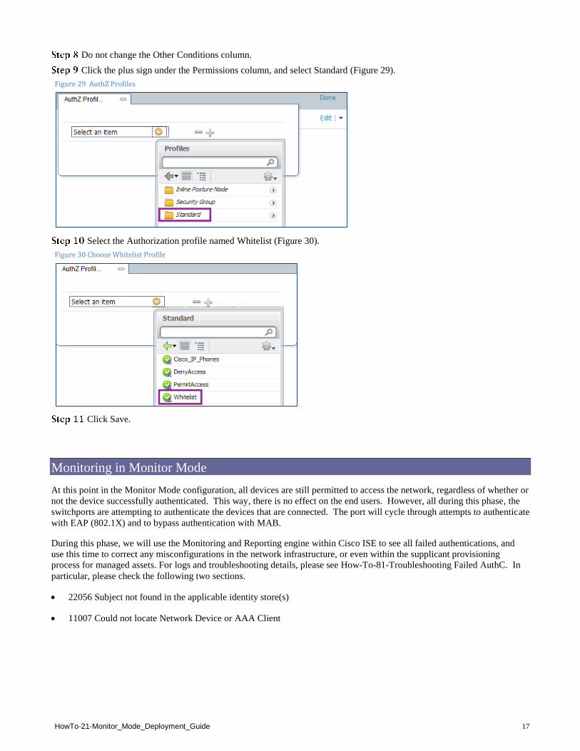
Do not change the Other Conditions column.
Click the plus sign under the Permissions column, and select Standard (Figure 29).
Figure 29 AuthZ Profiles
Select the Authorization profile named Whitelist (Figure 30).
Figure 30 Choose Whitelist Profile
Click Save.
Monitoring in Monitor Mode
At this point in the Monitor Mode configuration, all devices are still permitted to access the network, regardless of whether or
not the device successfully authenticated. This way, there is no effect on the end users. However, all during this phase, the
switchports are attempting to authenticate the devices that are connected. The port will cycle through attempts to authenticate
with EAP (802.1X) and to bypass authentication with MAB.
During this phase, we will use the Monitoring and Reporting engine within Cisco ISE to see all failed authentications, and
use this time to correct any misconfigurations in the network infrastructure, or even within the supplicant provisioning
process for managed assets. For logs and troubleshooting details, please see How-To-81-Troubleshooting Failed AuthC. In
particular, please check the following two sections.
22056 Subject not found in the applicable identity store(s)
11007 Could not locate Network Device or AAA Client
HowTo-21-Monitor_Mode_Deployment_Guide 18
Appendix A: References
Cisco TrustSec System:
http://www.cisco.com/go/trustsec
http://www.cisco.com/en/US/solutions/ns340/ns414/ns742/ns744/landing_DesignZone_TrustSec.html
Device Configuration Guides:
Cisco Identity Services Engine User Guides:
http://www.cisco.com/en/US/products/ps11640/products_user_guide_list.html
For more information about Cisco IOS Software, Cisco IOS XE Software, and Cisco NX-OS Software releases, please refer
to following URLs:
For Cisco Catalyst 2900 series switches:
http://www.cisco.com/en/US/products/ps6406/products_installation_and_configuration_guides_list.html
For Cisco Catalyst 3000 series switches:
http://www.cisco.com/en/US/products/ps7077/products_installation_and_configuration_guides_list.html
For Cisco Catalyst 3000-X series switches:
http://www.cisco.com/en/US/products/ps10745/products_installation_and_configuration_guides_list.html
For Cisco Catalyst 4500 series switches:
http://www.cisco.com/en/US/products/hw/switches/ps4324/products_installation_and_configuration_guides_list.ht
ml
For Cisco Catalyst 6500 series switches:
http://www.cisco.com/en/US/products/hw/switches/ps708/products_installation_and_configuration_guides_list.html
For Cisco ASR 1000 series routers:
http://www.cisco.com/en/US/products/ps9343/products_installation_and_configuration_guides_list.html
For Cisco Wireless LAN Controllers: http://www.cisco.com/en/US/docs/wireless/controller/7.2/configuration/guide/cg.html