cisco support community expert series...
TRANSCRIPT

© 2013 Cisco and/or its affiliates. All rights reserved. 1
Cisco Support Community Expert Series Webcast: Mobile Wireless: How Your Cellular Phone Surfs the Internet Deepak Michael Network Consulting Engineer
March 5, 2013

2 © 2013 Cisco and/or its affiliates. All rights reserved.
• Today’s featured expert is Cisco Support Network Consulting Engineer Deepak Michael
• Ask him questions now about Wireless Mobility
Deepak Michael
Expert’s photo

3 © 2013 Cisco and/or its affiliates. All rights reserved.
Mobile Wireless: How Your Cellular Phone Surfs the Internet
Panel of Experts
Event Date: March 5, 2013
Archit Sinha NCE
Kirit Soheliya NCE

4 © 2013 Cisco and/or its affiliates. All rights reserved.
Today’s presentation will include audience polling questions
We encourage you to participate!

5 © 2013 Cisco and/or its affiliates. All rights reserved.
If you would like a copy of the presentation slides, click the PDF link in the chat box on the right or go to
https://supportforums.cisco.com/community/netpro/wireless-mobility/begin-wireless
Or, https://supportforums.cisco.com/docs/DOC-30239

6 © 2013 Cisco and/or its affiliates. All rights reserved.
Everyone who joins today’s webcast will receive:
125 Cisco Preferred Access Points!

7 © 2013 Cisco and/or its affiliates. All rights reserved.
a) I know basic WiFi concepts, but no idea about Mobile internet.
b) I theoretically know Mobile Wireless, but no practical experience.
c) I’m playing with it in the lab.
d) I’m running it in production.
What is your level of experience with Mobile wireless technology?

8 © 2013 Cisco and/or its affiliates. All rights reserved.
Use the Q&A panel to submit your questions. Experts will start responding those

9 © 2013 Cisco and/or its affiliates. All rights reserved.
Deepak Michael
2/28/2013 Network Consulting Engineer

10 © 2013 Cisco and/or its affiliates. All rights reserved.
How Your Cellular Phone Surfs the Internet • LTE overview & real world examples • Control and User plane protocol • LTE Architecture • Aggregation Service Router (ASR) 5500 • LTE Call Flow • Q&A

11 © 2013 Cisco and/or its affiliates. All rights reserved.
LTE overview & real world examples

12 © 2013 Cisco and/or its affiliates. All rights reserved.
• Look at your smart phone today capable of an array of applications ranging from shopping on-line, making dinner reservations and downloading music. Who would have thought its predecessor would come from the two mobile devices below.
• In 1973 Martin Cooper invented the first cellular phone. Weighing 2 pounds, costing ~4K and with 30 minutes talk time.
• Cellular phone were used predominantly by the government and some businesses due to high cost.
à Enter the era of LTE ushering a mobile wireless landscape that has no boundaries offering speeds over 100 MBps.
13 © 2013 Cisco and/or its affiliates. All rights reserved.
• Long Term Evolution also known as LTE is made possible through the 3rd Generation Partnership Project (3GPP).
• 3GPP is a collaboration between groups of telecommunications associations, known as the Organizational Partners. The initial scope of 3GPP was to make a globally applicable third-generation (3G) mobile phone system specification based on evolved Global System for Mobile Communications (GSM) specifications within the scope of the International Mobile Telecommunications-2000 project of the International Telecommunication Union (ITU).
• 3GPP defines the standards to allow different vendors the ability to work in tandem leading to transparent global mobility for the end user.
• Find more 3GPP @ http://www.3gpp.org/specifications

14 © 2013 Cisco and/or its affiliates. All rights reserved.
• Today mobile devices maybe found everywhere performing functions never explored with wire line technology.
• Operators such a AT&T & Verizon have over 300 Machine 2 Machine (M2M) devices certified for enterprise customers.
• What are these devices doing? - Monitoring prescriptions usage - Asset monitoring - Location services - Inventory control - Usage reporting - Security - Streaming music in your car - And much more!

15 © 2013 Cisco and/or its affiliates. All rights reserved.
- Where are we going with connected devices?

16 © 2013 Cisco and/or its affiliates. All rights reserved.
a) Theoretical knowledge only
b) I have minimal working experience with release 8
c) I have expert knowledge with 1 or more release 8
How familiar are you with 3GPP Release 8?

17 © 2013 Cisco and/or its affiliates. All rights reserved.
Use the Q&A panel to submit your questions. Experts will start responding those

18 © 2013 Cisco and/or its affiliates. All rights reserved.
Control and User plane protocols

19 © 2013 Cisco and/or its affiliates. All rights reserved.
• Unlike IP networks that rely on source & destination routing, mobile networks require constant updates in the from of control plane messaging.
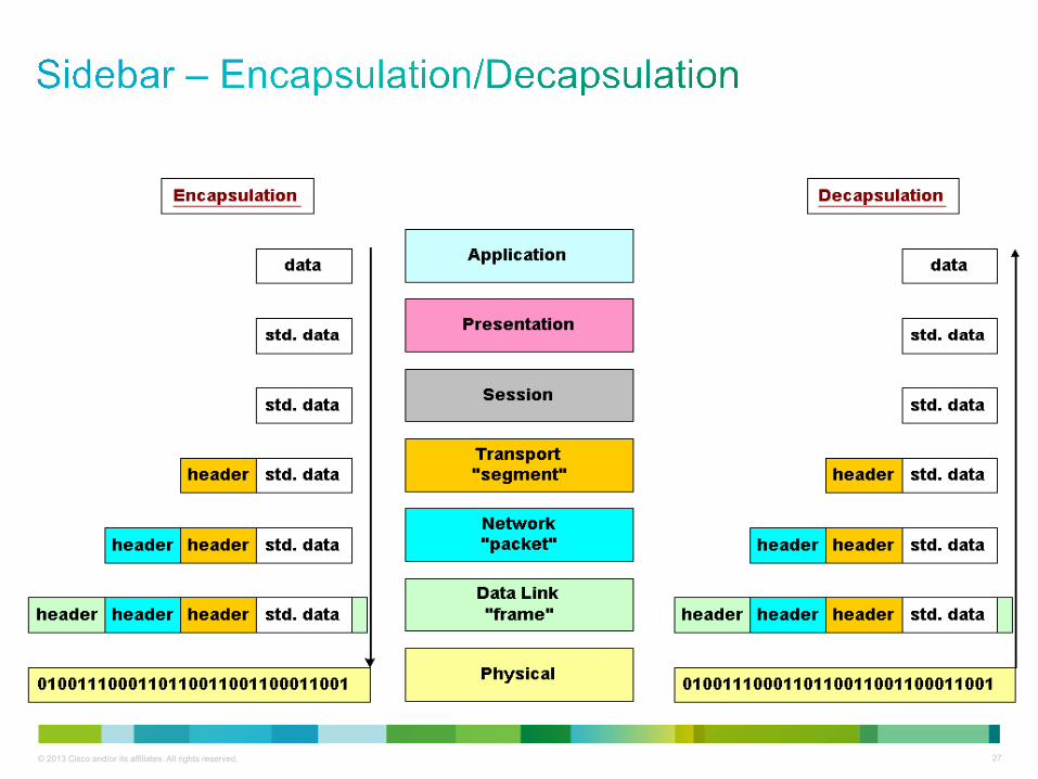
• IP is the means of reaching the devices within the network, however mobile networks utilizes a process of encapsulation and decapsulation via control & user plane messaging.
• Remember the slide about 3GPP? 3GPP creates standards to achieve both control & user plane protocols.
• Think of Control plane as set-up messages and keep lives while user plane is actual data i.e. HTTP wrapped in GTP.
• Common control plane protocols include GTP-C, S1AP while GTP-U is the predominate user plane protocol.
20 © 2013 Cisco and/or its affiliates. All rights reserved.
- Per 23.401 section 5.1.1
• The control plane consists of protocols for control and support of the user plane functions.
• Controlling the E-UTRA network access connections, such as attaching to and detaching from E-UTRAN;
• Controlling the attributes of an established network access connection, such as activation of an IP address;
• Controlling the routeing path of an established network connection in order to support user mobility; and
• Controlling the assignment of network resources to meet changing user demands.

21 © 2013 Cisco and/or its affiliates. All rights reserved.
SCTP
L2
L1
IP
L2
L1
IP
SCTP
S1-MME eNodeB MME
S1-AP S1-AP
NAS
MAC
L1
RLC
PDCP
UE
RRC
MAC
L1
RLC
PDCP RRC
LTE-Uu
NAS Relay

22 © 2013 Cisco and/or its affiliates. All rights reserved.
UDP
L2
L1
IP
L2
L1
IP
UDP
S11 MME S-GW
GTP-C GTP-C
UDP
L2
L1
IP
L2
L1
IP
UDP
S5 or S8 S - GW P - GW
GTP - C GTP - C
23 © 2013 Cisco and/or its affiliates. All rights reserved.
- Per 29.060
• The user plane messages are used to carry user data packets, and signalling messages for path management and error indication.
• The GTP-U protocol entity provides packet transmission and reception services to user plane entities in the GGSN, in the SGSN and, in UMTS systems, in the RNC. In LTE GTP-U is carried amongst EnB,SGSN,SGW & PGW.
• The GTP-U protocol entity receives traffic from a number of GTP-U tunnel endpoints and transmits traffic to a number of GTP-U tunnel endpoints. There is a GTP-U protocol entity per IP address.

24 © 2013 Cisco and/or its affiliates. All rights reserved.
Serving G W PDN GW
S5/S8
MAC
GSM RF
N etwor k S ervice L1bis
RLC BSSGP
Relay
LLC BSSGP
IP
L2
SNDCP GTP - U
Relay
Network Service L1bis L1
UDP GTP - U GTP - U
UDP
IP IP
L2
Relay
L2
L1 L1
LLC
RLC
MAC
GSM RF
SNDCP
IP
Application
IP
L2
L1
UDP
IP
SGi S4 Gb Um SGSN BS UE
UDP
GTP - U
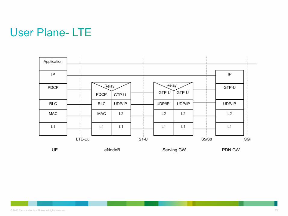
25 © 2013 Cisco and/or its affiliates. All rights reserved.
Serving GW PDN GW
S5/S8a
GTP-U GTP-U
UDP/IP UDP/IP
L2
Relay
L2
L1 L1
PDCP
RLC
MAC
L1
IP
Application
UDP/IP
L2
L1
GTP-U
IP
SGi S1-U LTE-Uu
eNodeB
RLC UDP/IP
L2
PDCP GTP-U
Relay
MAC
L1 L1
UE
26 © 2013 Cisco and/or its affiliates. All rights reserved.
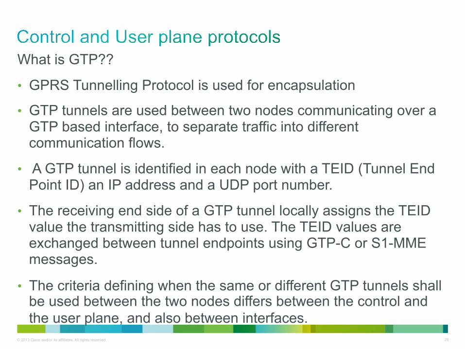
What is GTP??
• GPRS Tunnelling Protocol is used for encapsulation
• GTP tunnels are used between two nodes communicating over a GTP based interface, to separate traffic into different communication flows.
• A GTP tunnel is identified in each node with a TEID (Tunnel End Point ID) an IP address and a UDP port number.
• The receiving end side of a GTP tunnel locally assigns the TEID value the transmitting side has to use. The TEID values are exchanged between tunnel endpoints using GTP-C or S1-MME messages.
• The criteria defining when the same or different GTP tunnels shall be used between the two nodes differs between the control and the user plane, and also between interfaces.
27 © 2013 Cisco and/or its affiliates. All rights reserved.

28 © 2013 Cisco and/or its affiliates. All rights reserved.
Layer 3 Tunneling Protocol with mobility support
UDP IP GTP Payload (IP or PPP)
Identify the flow between the ENB and SGW
Identify the GTP’s well known port (2152)
Identify the GTP session
Identify the flow between the MS and remote host

29
• Identifies a tunnel endpoint in receiving GTP-C/GTP-U protocol entity
MME GGSN
Assign local TEID A5A5A5A5 Assign local TEID ECECECEC
GTP-C Request message
GTP-C Response message
Message flow to exchange Assigned TEIDs
Tunnel established GSN specify peer’s TEID in Subsequent messages
GTP v2 Tunnel

30
Message Type value (Decimal)
Message GTP-C GTP-U
0 Reserved
1 Echo Request X X
2 Echo Response X X
3 Version Not Supported Indication X
4 to 24 Reserved for S101 interface
25 to 31 Reserved for Sv interface
SGSN/MME to PGW (S4/S11, S5/S8)
32 Create Session Request X
33 Create Session Response X
34 Modify Bearer Request X
35 Modify Bearer Response X
36 Delete Session Request X
37 Delete Session Response X
Example of Commons GTP-C and GTP-U messages taken from 29.274

31
Create Session Request Expanded with Information Elements. The direction of this message shall be from MME/S4-SGSN to SGW and from SGW to PGW • The Create Session Request message shall be sent on the S11 interface by
the MME to the SGW, and on the S5/S8 interface by the SGW to the PGW as part of the procedures:
- E-UTRAN Initial Attach - UE requested PDN connectivity Information
elements P Condition / Comment IE Type
IMSI M IMSI MSISDN C For an E-UTRAN Initial Attach the IE shall be
included when used on the S11 interface, if provided in the subscription data from the HSS. For a PDP Context Activation procedure the IE shall be included when used on the S4 interface, if provided in the subscription data from the HSS. The IE shall be included for the case of a UE Requested PDN Connectivity, it shall be included if the MME has it stored for that UE. It shall be included when used on the S5/S8 interfaces if provided by the MME/SGSN.
MSISDN
ME Identity (MEI) C The MME shall include the ME Identity (MEI) IE, if it is available.
MEI
RAT Type M RAT Type

32 © 2013 Cisco and/or its affiliates. All rights reserved.
LTE Architecture
33 © 2013 Cisco and/or its affiliates. All rights reserved.
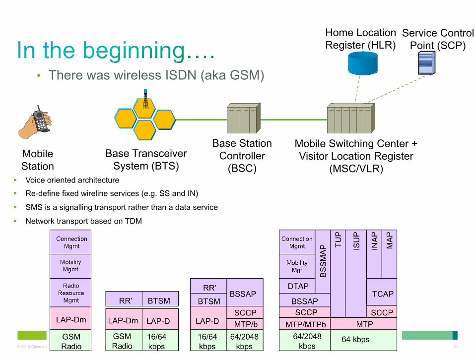
§ Voice oriented architecture
§ Re-define fixed wireline services (e.g. SS and IN)
§ SMS is a signalling transport rather than a data service
§ Network transport based on TDM
• There was wireless ISDN (aka GSM)
Base Station Controller
(BSC)
Mobile Switching Center + Visitor Location Register
(MSC/VLR) Base Transceiver
System (BTS) Mobile Station
Home Location Register (HLR)
Service Control Point (SCP)
34 © 2013 Cisco and/or its affiliates. All rights reserved.
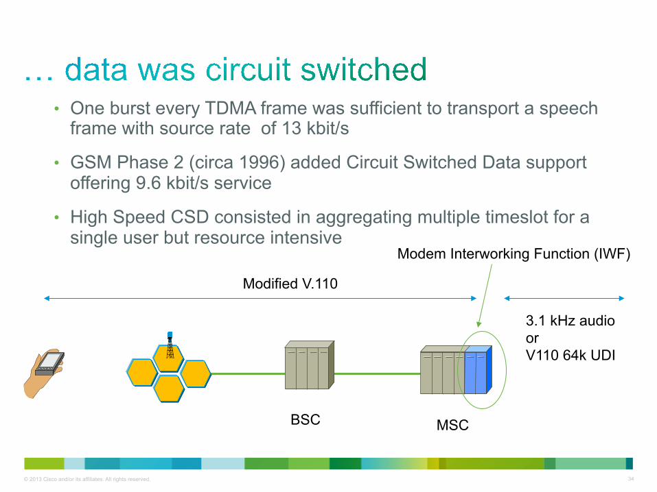
• One burst every TDMA frame was sufficient to transport a speech frame with source rate of 13 kbit/s
• GSM Phase 2 (circa 1996) added Circuit Switched Data support offering 9.6 kbit/s service
• High Speed CSD consisted in aggregating multiple timeslot for a single user but resource intensive
BSC MSC
Modem Interworking Function (IWF)
Modified V.110
3.1 kHz audio or V110 64k UDI

35 © 2013 Cisco and/or its affiliates. All rights reserved.
BSC MSC/VLR Gateway MSC BTS
Packet Control Unit (PCU) Serving GPRS
Support Node (SGSN)
Gateway GPRS Support Node
(GGSN)
IP

36 © 2013 Cisco and/or its affiliates. All rights reserved.
• First step towards an all IP network
• Designed to accommodate greater packet throughput
• Core network remains largely unchanged from 2.5G
• Migration to ATM for Radio Access Transport
• More control into the RNC
3G RNC
3G MSC
3G SGSN GGSN
IP
ATM/AAL2 ATM/AAL5
Node B
PSTN

37 © 2013 Cisco and/or its affiliates. All rights reserved.
• So hopefully WCDMA got it right on packet services…
Radio Network Controller (RNC)
3G SGSN GGSN
Iu-ps Gn/Gp
NodeB

38 © 2013 Cisco and/or its affiliates. All rights reserved.
Serving RNC 3G SGSN GGSN
Gn Iu-ps
Drift RNC Node B
HSDPA Removes Drift RNC and adds intelligence to the Node B
HSPA+: Distribute RNC Data plane to Node B

39 © 2013 Cisco and/or its affiliates. All rights reserved.
• Highlighting the growing importance of IP transport
3G MSC-S
3G SGSN GGSN
Core IP
IP RAN w/ ATM PW or Native IP
Node B
PSTN
3G RNC 3G MGW
HLR/HSS
SGW

40
2G and 2.5G Network Architecture
SGSN GGSNGiGn
BSCBTS
A-bis
GMSC
TDMVLR
Gb
MSC
A
Internet
GiPDP Context
IPSNDCP
LLCRLCMAC
TDMA/GMSK
RLCMAC
TDMA/GMSK
BSSGPNetwork Service
L1bis
SNDCPLLC
BSSGPNetwork Service
L1bis
GTPUDP
IPLayer 2Layer 1
IPGTPUDP
IPLayer 2Layer 1
Um Gb Gn
PDP Context
HLR
SMSC
PCU
Structured, Centralised Approach
Less Rigid, Distributed Approach i.e. moving intelligence into the network
S-GW
S-GW
MME
MME
P-GW
IP IP

41
Native IP
GGSN
SGSN
Serving RNC
Drift RNC
Node B
IP Tunnel
MA
C, Security
Layer 3
UMTS LTE
IP Tunnel
IP Tunnel
Enhanced Node B
Serving GW
PDN GW
MA
C
Secu
rity
Laye
r 3
Native IP
MME
Collapse into one or two nodes for non-roaming users and fully meshed access network
Enhanced Packet Core (EPC)
42 © 2013 Cisco and/or its affiliates. All rights reserved.
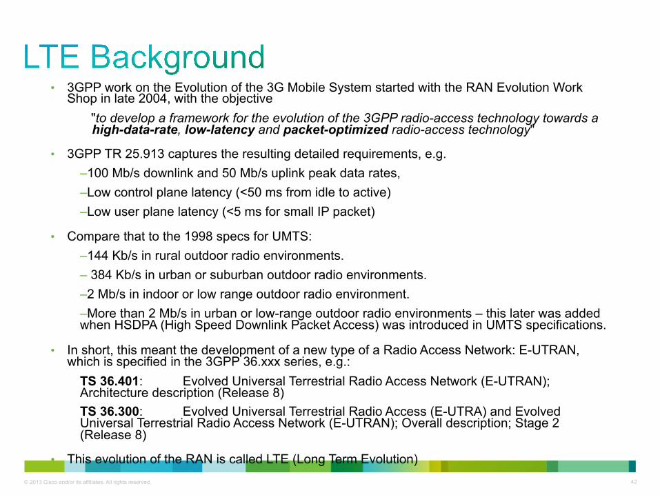
• 3GPP work on the Evolution of the 3G Mobile System started with the RAN Evolution Work Shop in late 2004, with the objective
"to develop a framework for the evolution of the 3GPP radio-access technology towards a high-data-rate, low-latency and packet-optimized radio-access technology"
• 3GPP TR 25.913 captures the resulting detailed requirements, e.g. – 100 Mb/s downlink and 50 Mb/s uplink peak data rates, – Low control plane latency (<50 ms from idle to active) – Low user plane latency (<5 ms for small IP packet)
• Compare that to the 1998 specs for UMTS: – 144 Kb/s in rural outdoor radio environments. – 384 Kb/s in urban or suburban outdoor radio environments. – 2 Mb/s in indoor or low range outdoor radio environment. – More than 2 Mb/s in urban or low-range outdoor radio environments – this later was added when HSDPA (High Speed Downlink Packet Access) was introduced in UMTS specifications.
• In short, this meant the development of a new type of a Radio Access Network: E-UTRAN, which is specified in the 3GPP 36.xxx series, e.g.:
TS 36.401: Evolved Universal Terrestrial Radio Access Network (E-UTRAN); Architecture description (Release 8) TS 36.300: Evolved Universal Terrestrial Radio Access (E-UTRA) and Evolved Universal Terrestrial Radio Access Network (E-UTRAN); Overall description; Stage 2 (Release 8)
• This evolution of the RAN is called LTE (Long Term Evolution)
43
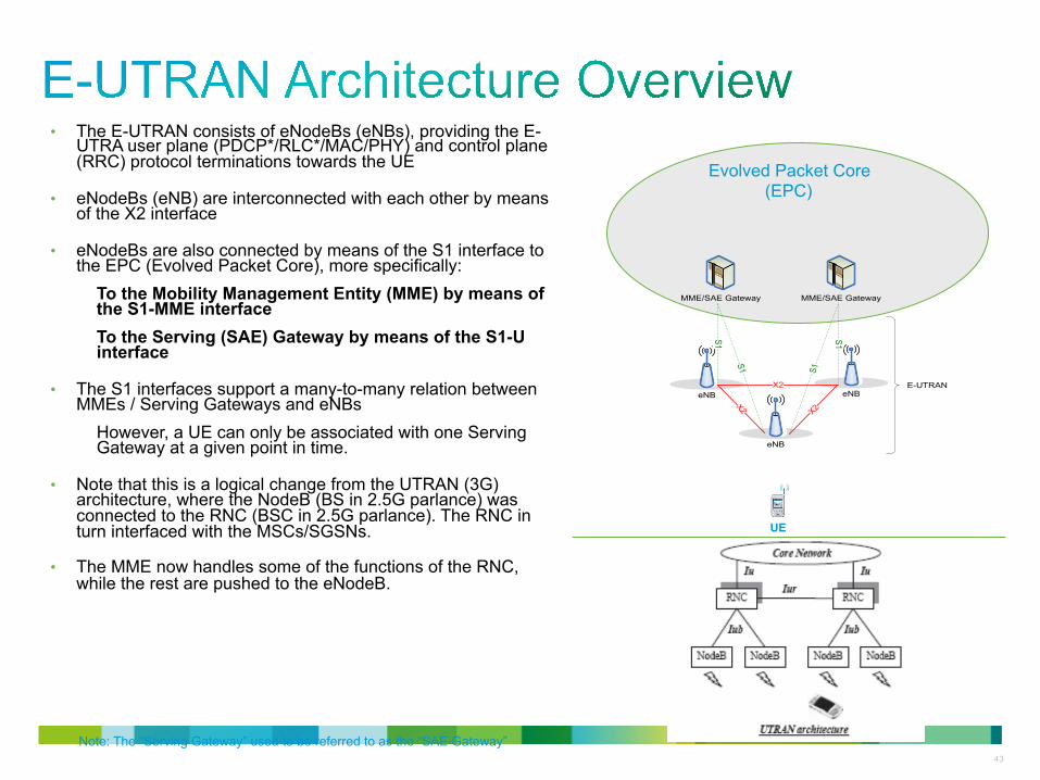
• The E-UTRAN consists of eNodeBs (eNBs), providing the E-UTRA user plane (PDCP*/RLC*/MAC/PHY) and control plane (RRC) protocol terminations towards the UE
• eNodeBs (eNB) are interconnected with each other by means of the X2 interface
• eNodeBs are also connected by means of the S1 interface to the EPC (Evolved Packet Core), more specifically:
To the Mobility Management Entity (MME) by means of the S1-MME interface To the Serving (SAE) Gateway by means of the S1-U interface
• The S1 interfaces support a many-to-many relation between MMEs / Serving Gateways and eNBs
However, a UE can only be associated with one Serving Gateway at a given point in time.
• Note that this is a logical change from the UTRAN (3G) architecture, where the NodeB (BS in 2.5G parlance) was connected to the RNC (BSC in 2.5G parlance). The RNC in turn interfaced with the MSCs/SGSNs.
• The MME now handles some of the functions of the RNC, while the rest are pushed to the eNodeB.
Note: The “Serving Gateway” used to be referred to as the “SAE Gateway”
eNB
MME/SAE Gateway MME/SAE Gateway
eNB
eNB
S1 S1
S1 S1
X2
X2X2
E-UTRAN
Evolved Packet Core (EPC)
UE
44 © 2013 Cisco and/or its affiliates. All rights reserved.
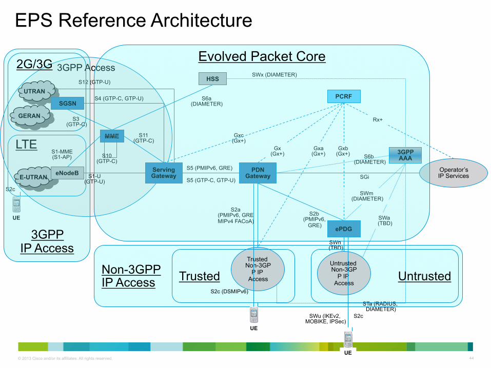
Non-3GPP IP Access
3GPP Access
EPS Reference Architecture
E-UTRAN PDN
Gateway Serving Gateway eNodeB
PCRF
Operator’s IP Services
HSS
Gxc (Gx+)
S11 (GTP-C)
S1-U (GTP-U)
S2b (PMIPv6,
GRE)
MME
S5 (PMIPv6, GRE)
S6a (DIAMETER)
S1-MME (S1-AP)
GERAN
S4 (GTP-C, GTP-U) UTRAN
SGSN
Trusted Non-3GP
P IP Access
Untrusted Non-3GP
P IP Access
S3 (GTP-C)
S12 (GTP-U)
S10 (GTP-C)
S5 (GTP-C, GTP-U)
Gx (Gx+)
Gxb (Gx+)
SWx (DIAMETER)
STa (RADIUS, DIAMETER)
ePDG
3GPP AAA
SWn (TBD)
S2c (DSMIPv6)
S2c
S6b (DIAMETER)
SWm (DIAMETER)
SGi
SWa (TBD)
Gxa (Gx+)
Rx+
S2c
UE
UE
UE
SWu (IKEv2, MOBIKE, IPSec)
S2a (PMIPv6, GRE MIPv4 FACoA)
Trusted Untrusted
LTE
3GPP IP Access
Evolved Packet Core
2G/3G

45 © 2013 Cisco and/or its affiliates. All rights reserved.
3GPP Access
E-UTRAN PDN
Gateway Serving Gateway eNodeB
PCRF
Operator’s IP Services
HSS
Gxc (Gx+)
S11 (GTP-C)
S1-U (GTP-U)
S2b (PMIPv6,
GRE)
MME
S5 (PMIPv6, GRE)
S6a (DIAMETER)
S1-MME (S1-AP)
GERAN
S4 (GTP-C, GTP-U) UTRAN
SGSN
Trusted Non-3GP
P IP Access
Untrusted Non-3GP
P IP Access
S3 (GTP-C)
S12 (GTP-U)
S10 (GTP-C)
S5 (GTP-C, GTP-U)
Gx (Gx+)
Gxb (Gx+)
SWx (DIAMETER)
STa (RADIUS, DIAMETER)
ePDG
3GPP AAA
SWn (TBD)
S2c (DSMIPv6)
S2c
S6b (DIAMETER)
SWm (DIAMETER)
SGi
SWa (TBD)
Gxa (Gx+)
Rx+
S2c
UE
UE
UE
SWu (IKEv2, MOBIKE, IPSec)
S2a (PMIPv6, GRE MIPv4 FACoA)
Simplified and flattened RAN with IP to the edge
• Radio resource management, incl. handovers • Interacts with MME for all signaling plane processing • Exchanges user plane traffic with Serving GW
Integrated Non-3GPP Access Network (wireless or fixed)
• Wireless or fixed access network • Close integration with the EPC • Supports mobility, policy and AAA interfaces to the EPC
Support for non-integrated non-3GPP Access Networks
• EPC point of attachment for untrusted IP access networks (“Internet”) • IPSec to UE for EPC connectivity • Network-based mobility towards PDNGW (PMIPv6)
Data Plane anchoring for 3GPP Access Networks with 2G/3G interworking
• Anchor point for 3GPP IP Access Networks only (2G/3G/LTE) • Processes all IP packets to/from UE • Controlled by MME • Uses network-based mobility towards PDNGW (GTP or PMIPv6) • Always in same network as eNodeB
Subscriber-aware Policy Server • Supports dynamic policy and charging rules for all IP access networks (3GPP and non-3GPP) • Has subscriber-specific policy profile for the IP session (QoS, charging, DPI, etc.) • May provide flow-specific policies as well • Can be in home and/or visited network
Subscriber-aware Data Plane anchoring for all Access Networks
• Common anchor point for all IP Access Networks (3GPP and non-3GPP) • Assigns/owns IP-address for UE (v4/v6) • Processes all IP packets to/from UE • Can be in home and/or visited network
E-UTRAN Control Plane with 2G/3G interworking
• Handles all signaling traffic (no user plane traffic) • Interacts with HSS for user authentication, profile download, etc. • Interacts with eNodeB and Serving GW to control tunnels, paging, etc. • Interacts with SGSN for 2G/3G

46 © 2013 Cisco and/or its affiliates. All rights reserved.
a) Theoretical knowledge only
b) I have minimal hands on working with EPC
c) I have expert knowledge pertaining to EPC
d) I work with boxes that communicate with EPC
How familiar are you with EPC ?

47 © 2013 Cisco and/or its affiliates. All rights reserved.
Use the Q&A panel to submit your questions. Experts will start responding those

48 © 2013 Cisco and/or its affiliates. All rights reserved.
Aggregation Service Router (ASR) 5500
49 © 2013 Cisco and/or its affiliates. All rights reserved.
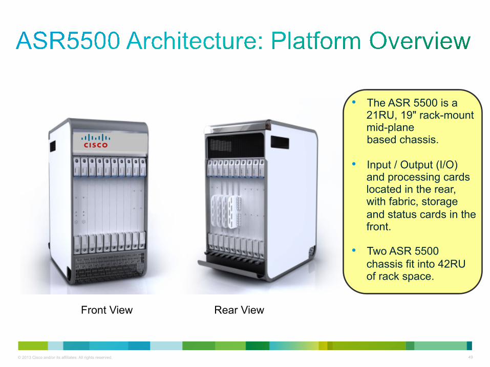
• The ASR 5500 is a 21RU, 19" rack-mount mid-plane based chassis.
• Input / Output (I/O) and processing cards located in the rear, with fabric, storage and status cards in the front.
• Two ASR 5500 chassis fit into 42RU of rack space.
Front View Rear View

50 © 2013 Cisco and/or its affiliates. All rights reserved.

51 © 2013 Cisco and/or its affiliates. All rights reserved.
Front Rear Air intake
Front-to-back airflow
Front fan tray
System Status Card slots (11-12)
Fabric Storage Card slots (13-18)
Front fan tray
Management and I/O slots (5-6)
Data Processing Card slots (1-4, 7-10)
Power supplies Rear fan tray
Rear fan tray

52 © 2013 Cisco and/or its affiliates. All rights reserved.
ASR 5500 Hardware - Card Types
Rear Cards (21.75”H x 1.75”W x 19.5”D )
• Management I/O (MIO)
• Data Processing Card (DPC)
Front Cards (19.75”H x1.75”W x 6.75”D)
• Fabric and Storage Card (FSC)
• System Status Card (SSC)
Front Cards Rear Cards
SSC MIO DPC FSC

53 © 2013 Cisco and/or its affiliates. All rights reserved.
MIO
• Management Input/output Card
1 CPU Subsystem 96 GB of RAM
Management, VPN, Signaling
USB port for an external flash drive
Two 1 GbE ports (used only for local context (OAM))
RS-232 serial console for CLI management
4 x NPU I/O Subsystems
Mid-plane connections for chassis control operations
Total of ~200Gb/s FDX Line-Card I/O
I/O options hosted on 2 factory populated daughter cards
MIO Summary

54 © 2013 Cisco and/or its affiliates. All rights reserved.
• A Data Processing Card has:
2 identical CPU subsystems each with: 96 GB RAM (total 192 GB RAM per DPC) Hardware encryption engine on a daughter card NPU Subsystem for session data offload
75 Gbps data path to fabric 60 Gbps TM (for subscriber traffic)
Common subset of mid-plane connectors on the MIO allowing it to plug into the same slots as the MIO cards Manages subscriber sessions and control traffic
DPC
DPC Summary
55 © 2013 Cisco and/or its affiliates. All rights reserved.
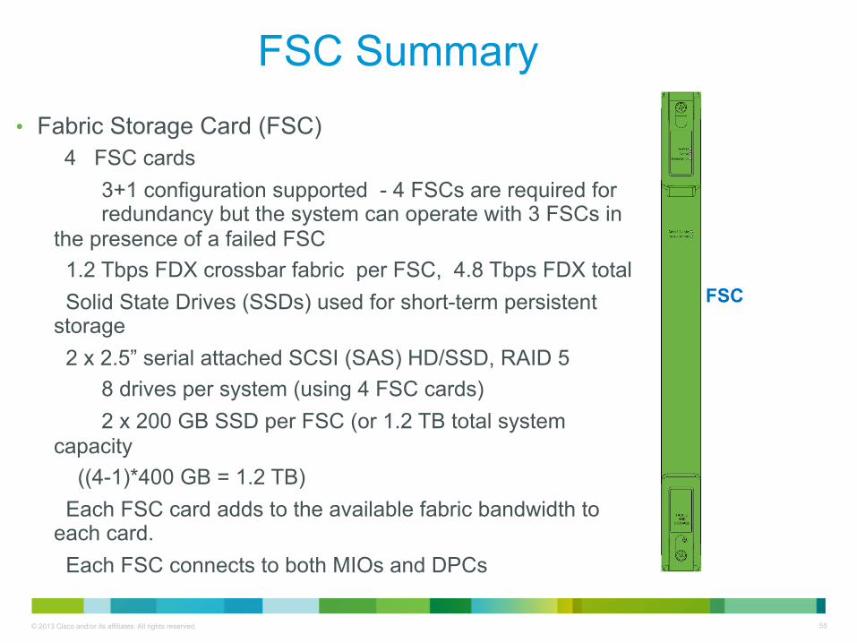
FSC Summary • Fabric Storage Card (FSC)
4 FSC cards 3+1 configuration supported - 4 FSCs are required for redundancy but the system can operate with 3 FSCs in
the presence of a failed FSC 1.2 Tbps FDX crossbar fabric per FSC, 4.8 Tbps FDX total Solid State Drives (SSDs) used for short-term persistent storage 2 x 2.5” serial attached SCSI (SAS) HD/SSD, RAID 5
8 drives per system (using 4 FSC cards) 2 x 200 GB SSD per FSC (or 1.2 TB total system
capacity ((4-1)*400 GB = 1.2 TB) Each FSC card adds to the available fabric bandwidth to each card. Each FSC connects to both MIOs and DPCs
FSC

56 © 2013 Cisco and/or its affiliates. All rights reserved.
SSC Summary
SSC
System Status Card (SSC)
2 per system (Active – Active) (minimum 1 SSC to be functional) Monitoring Temperature, airflow, current (all cards have this ability) System Power Monitors Power Filter Unit A1-4 and B1-4 feeds Also monitors the (-48 V) voltage level Audible Alarms – Cutoff (Panel or Remote) System Status LEDs – Major, Minor, Critical, Alarm Relays
57 © 2013 Cisco and/or its affiliates. All rights reserved.
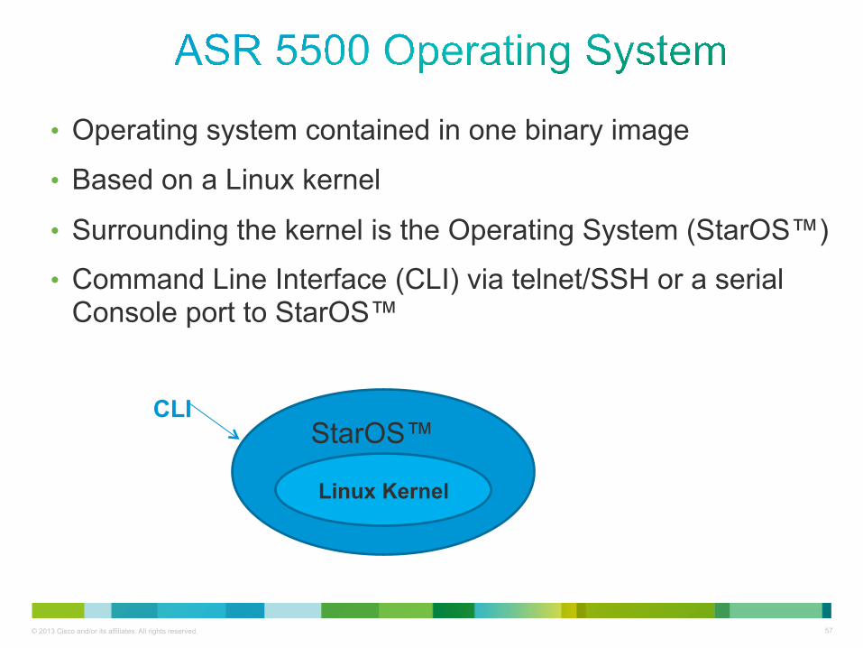
• Operating system contained in one binary image
• Based on a Linux kernel
• Surrounding the kernel is the Operating System (StarOS™)
• Command Line Interface (CLI) via telnet/SSH or a serial Console port to StarOS™
Linux Kernel
CLI StarOS™
58 © 2013 Cisco and/or its affiliates. All rights reserved.
• The ASR 5500 is a model of distributed processing
• All of the control processors (CPs) run the same binary image
• Sharing the same image across multiple CPs is complex, involving the distribution and synchronization of multiple software functions
• Software architecture is designed for redundancy
• Introduced well over a decade ago, field proven architecture
ASR 5500 Operating System

59 © 2013 Cisco and/or its affiliates. All rights reserved.
60 © 2013 Cisco and/or its affiliates. All rights reserved.
Software Architecture Overview • Redundancy, scalability and robust call processing
• Tasks communicate with each other as needed to share control and data signals
• Distributed processing across multiple tasks
• Distribution of the tasks is invisible to the user
• Distributed design provides fault containment via check-pointing of processes
• The self-healing attributes of the software architecture protects the user's data sessions while ensuring complete accounting data integrity
61 © 2013 Cisco and/or its affiliates. All rights reserved.
• Supports dynamic hardware removal/additions By migrating tasks from one card to another via software controls, application cards can be “hot swapped” to dynamically add capacity and perform maintenance operations without service interruption.
• Multiple context support The system can be fully virtualized to support multiple logical instances of each service. This eliminates the possibility of any one domain disrupting operations for all users in the event of a failure. Further, multiple context support allows operators to assign duplicate/overlapping IP address ranges in different contexts.
• Leverages third party software components: The use of the Linux operating system kernel enables reuse of many well-tested, stable, core software elements such as protocol stacks, management services, and application programs.
Software Architecture Overview (contd.)

62 © 2013 Cisco and/or its affiliates. All rights reserved.
Local (OAM) Corporate Network
• Sample Contexts
• A context is a logical grouping or mapping of configuration parameters that pertain to various physical ports, logical IP interfaces, and services. A context can be thought of as a virtual private network (VPN).
SGI internet
PCRF_BILLING Media?on/PCRF
SRP
SAEGW UE/eNB/MME
LAWFUL_INTERFACE Content Delivery

63 © 2013 Cisco and/or its affiliates. All rights reserved.
eNB
pgw-‐service PGW_SVC
ggsn-‐service GGSN_SVC
interface SAEGW-‐VLAN412 192.168.10.1/27
2104:ae00:1013:800::3/64
interface SAEGW-‐VLAN402 192.168.20.1/27
2104:ae00:1013:804::3/64
ECMP
gtpu-‐service PGW_S5_DATA_SVC
egtp-‐service PGW_S5_CTRL_SVC
egtp-‐service SGW_S5_CTRL_SVC
egtp-‐service SGW_S11_CTRL_SVC
sgw-‐service SGW_SVC
interface SGW_GTPC_IN_LB 140.156.12.97/32
interface SGW_GTPU_IN_LB_IPV4 140.156.12.98/32
interface SGW_GTPU_IN_LB_IPv6 2104:ae00:1013:b00::8/128
interface PGW_GTPC/U_IN_LB 140.156.12.100/32
interface SGW_GPTU/C_OUT_LB 140.156.12.99/32
gtpu-‐service SGW_S5_DATA_SVC
gtpu-‐service SGW_S1u_DATA_SVC
MME
SGSN SAEGW(Context)

64 © 2013 Cisco and/or its affiliates. All rights reserved.
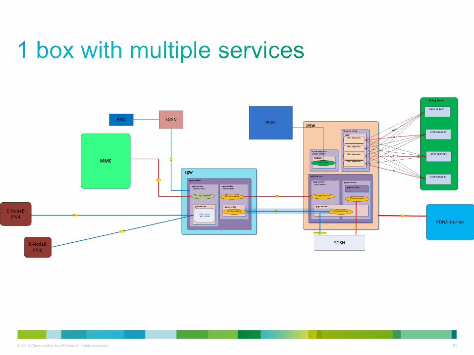
• Services are configured to enable certain functionality. Following are the services configured under SAEGW context. - Gateway GPRS Support Node (GGSN) services - Serving Gateway (S-GW) Services - PDN Gateway (P-GW) Services Ø CLI example from the configuration:
ggsn-service GGSN_SVC retransmission-timeout 3 max-retransmission 3 no echo-interval no gtpc ran-procedure-ready-delay plmn unlisted-sgsn home associate gtpu-service PGW_S5_DATA_SVC associate pgw-service PGW_SVC bind address 140.156.12.100 exit pgw-service PGW_SVC associate qci-qos-mapping QCI_DSCP_MAP associate ggsn-service GGSN_SVC associate egtp-service PGW_S5_CTRL_SVC

65 © 2013 Cisco and/or its affiliates. All rights reserved.
sgw-service SGW_SVC accounting context PCRF_BILLING gtpp group CGF1 associate ingress egtp-service SGW_S11_CTRL_SVC associate egress-proto gtp egress-context SAEGW egtp-service SGW_S5_CTRL_SVC associate accounting-policy SGW_CDR_profile associate qci-qos-mapping QCI_DSCP_MAP no reporting-action event-record gtpu-service PGW_S5_DATA_SVC bind ipv4-address 140.156.12.100 exit gtpu-service SGW_S1u_DATA_SVC bind ipv4-address 140.156.12.98 ipv6-address 2104:ae00:1013:b00:8/128 exit gtpu-service SGW_S5_DATA_SVC bind ipv4-address 140.156.12.99 exit
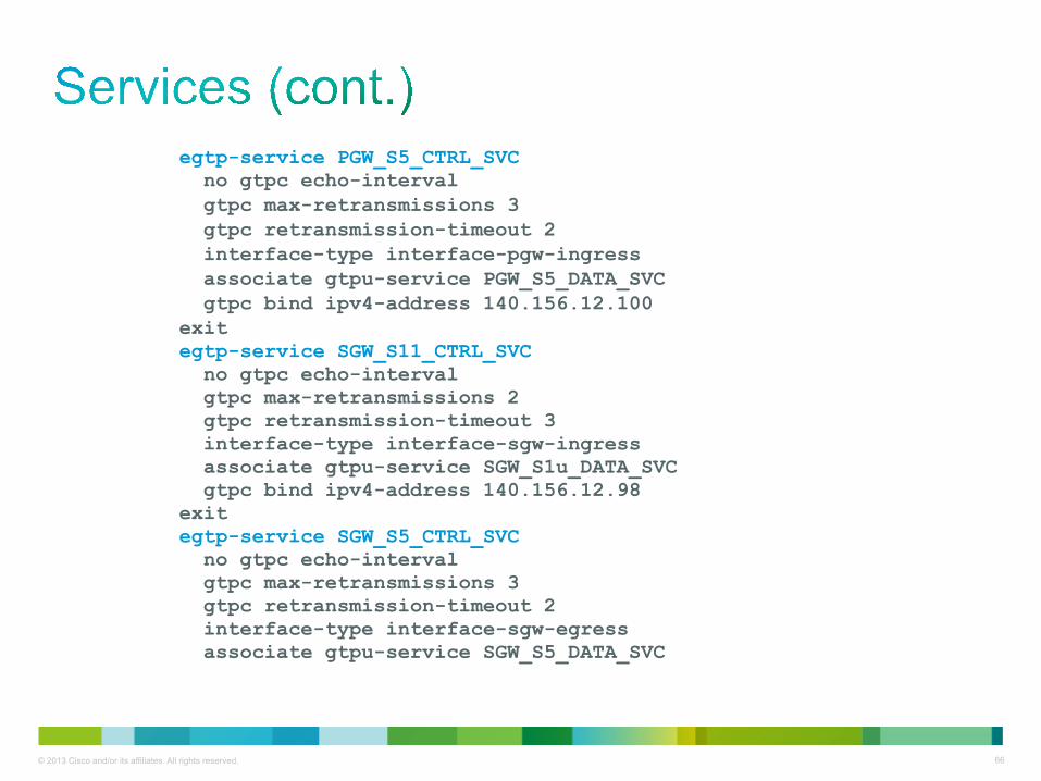
66 © 2013 Cisco and/or its affiliates. All rights reserved.
egtp-service PGW_S5_CTRL_SVC no gtpc echo-interval gtpc max-retransmissions 3 gtpc retransmission-timeout 2 interface-type interface-pgw-ingress associate gtpu-service PGW_S5_DATA_SVC gtpc bind ipv4-address 140.156.12.100 exit egtp-service SGW_S11_CTRL_SVC no gtpc echo-interval gtpc max-retransmissions 2 gtpc retransmission-timeout 3 interface-type interface-sgw-ingress associate gtpu-service SGW_S1u_DATA_SVC gtpc bind ipv4-address 140.156.12.98 exit egtp-service SGW_S5_CTRL_SVC no gtpc echo-interval gtpc max-retransmissions 3 gtpc retransmission-timeout 2 interface-type interface-sgw-egress associate gtpu-service SGW_S5_DATA_SVC

67 © 2013 Cisco and/or its affiliates. All rights reserved.
• A subscriber gets assigned an IP address out of "available" IP address(es) in the pool. IP addresses can be dynamically or statically assigned from a single pool or a group of IP pools. Ø CLI example from the configuration: context SGI-VLAN103_VLAN213
ip pool cisco-static 10.0.0.0 255.255.255.0 static srp-activate group-name cisco-1
ip pool cisco-private 10.10.10.1 255.255.255.248 private 0 srp-activate group-name cisco-2 vrf cisco

68 © 2013 Cisco and/or its affiliates. All rights reserved.
APNs • Access point Names (APN) dictates how subscriber authentication
and IP address assignment is to be handled for that APN. - APNs from the configuration: Ø CLI example from the configuration:
context SGI-VLAN103_VLAN213 apn cisco-static
bearer-control-mode mixed selection-mode subscribed sent-by-ms chosen-by-sgsn accounting-mode none gtpp group CGF1 accounting-context PCRF_BILLING idle-timeout-activity ignore-downlink
dns primary 192.168.10.1 dns secondary 192.168.10.2 timeout idle 14400 ip access-group ECS_ACL in ip access-group ECS_ACL out
ip context-name SGI-VLAN103_VLAN213
ip address pool name cisco-1 active-charging rulebase RB_01
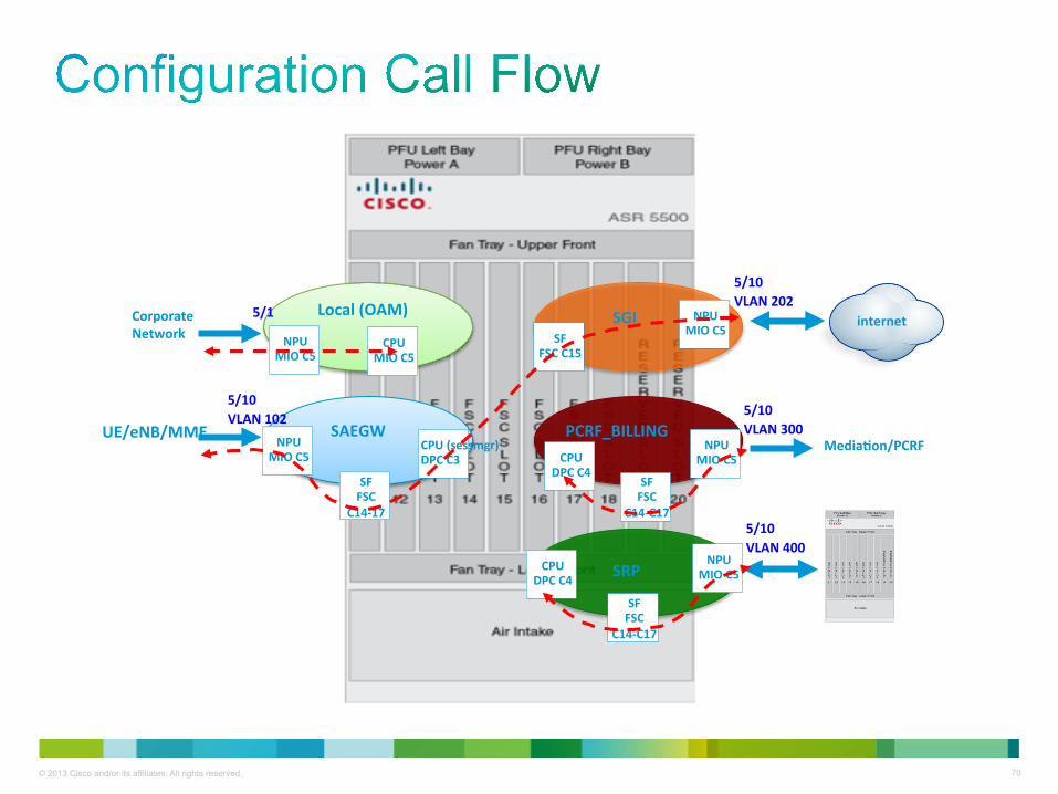
69 © 2013 Cisco and/or its affiliates. All rights reserved.
70 © 2013 Cisco and/or its affiliates. All rights reserved.
Local (OAM)
SAEGW
SGI
SRP
PCRF_BILLING
internet Corporate Network
Media?on/PCRF UE/eNB/MME
5/1
NPU MIO C5
SF FSC
C14-‐17
CPU (sessmgr) DPC C3
SF FSC C15
NPU MIO C5
5/10 VLAN 202
5/10 VLAN 102
NPU MIO C5
CPU MIO C5
CPU DPC C4
SF FSC
C14-‐C17
NPU MIO C5
5/10 VLAN 400
NPU MIO C5
5/10 VLAN 300
CPU DPC C4
SF FSC
C14-‐C17
71 © 2013 Cisco and/or its affiliates. All rights reserved.
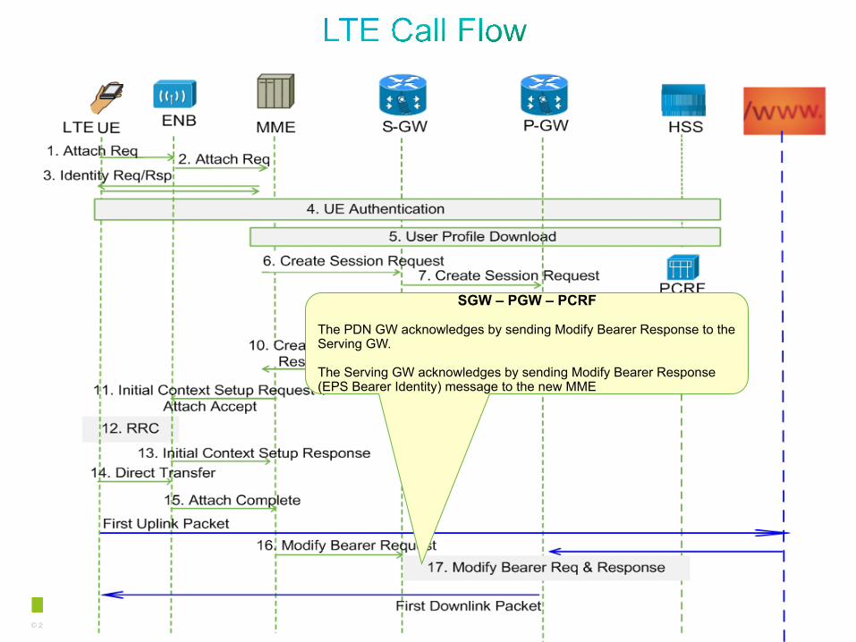
LTE Call Flow

72 © 2013 Cisco and/or its affiliates. All rights reserved.
Attach Request Ue à ENB (Uu)
Mobile initiated procedure to gain access into the network. Ue may include the following IEs: - APN - IMSI - Attach Type - PCO
Attach Request EnB à MME (S1-MME)
EnB will perform DNS lookup based on topology (Tracking Area ID) to find closet MME

73 © 2013 Cisco and/or its affiliates. All rights reserved.
Identity Request / Response
If the UE is unknown in both the old MME/SGSN and new MME, the new MME sends an Identity Request to the UE to request the IMSI. The UE responds with Identity Response (IMSI).

74 © 2013 Cisco and/or its affiliates. All rights reserved.
Ue Authentication
If no UE context for the UE exists anywhere in the network, if the Attach Request (sent in step 1) was not integrity protected, or if the check of the integrity failed, then authentication and NAS security setup to activate integrity protection and NAS ciphering are mandatory. Otherwise it is optional. If NAS security algorithm is to be changed, the NAS security setup is performed in this step.

75 © 2013 Cisco and/or its affiliates. All rights reserved.
MME à HSS (S6a)
• HSS will update the MME with the following: - APN profiles - VPLMN allowed - Subscriber Status
76 © 2013 Cisco and/or its affiliates. All rights reserved.
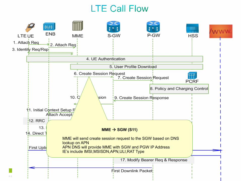
MME à SGW (S11)
MME will send create session request to the SGW based on DNS lookup on APN APN DNS will provide MME with SGW and PGW IP Address IE’s include IMSI,MSISDN,APN,ULI,RAT Type

77 © 2013 Cisco and/or its affiliates. All rights reserved.
SGW à PGW (S5)
The Serving GW creates a new entry in its EPS Bearer table and sends a Create Session Request to the PGW. Create Session req. obtain from MME will tell SGW applicable PGW IE’s include IMSI,MSISDN,APN,SGW TEID for control and user plane,QoS
78 © 2013 Cisco and/or its affiliates. All rights reserved.
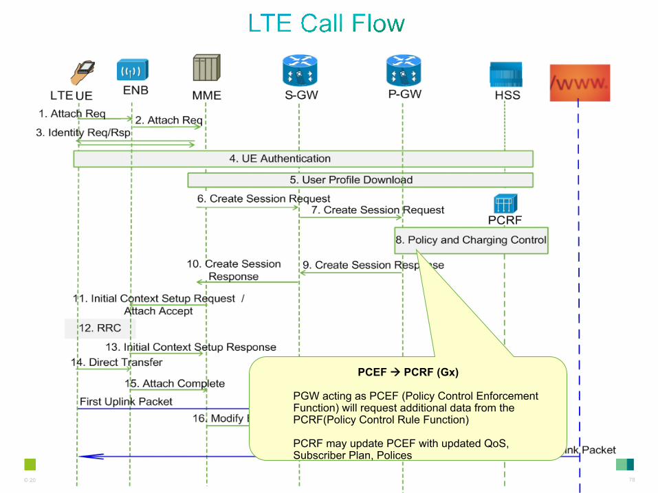
PCEF à PCRF (Gx)
PGW acting as PCEF (Policy Control Enforcement Function) will request additional data from the PCRF(Policy Control Rule Function) PCRF may update PCEF with updated QoS, Subscriber Plan, Polices
79 © 2013 Cisco and/or its affiliates. All rights reserved.
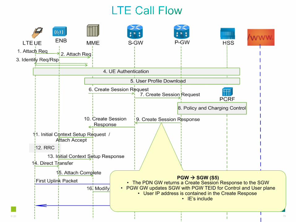
PGW à SGW (S5) • The PDN GW returns a Create Session Response to the SGW
• PGW GW updates SGW with PGW TEID for Control and User plane • User IP address is contained in the Create Respose
• IE’s include
80 © 2013 Cisco and/or its affiliates. All rights reserved.
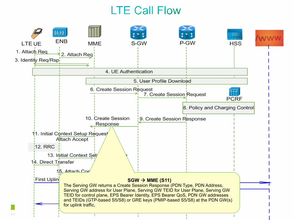
SGW à MME (S11)
The Serving GW returns a Create Session Response (PDN Type, PDN Address, Serving GW address for User Plane, Serving GW TEID for User Plane, Serving GW TEID for control plane, EPS Bearer Identity, EPS Bearer QoS, PDN GW addresses and TEIDs (GTP-based S5/S8) or GRE keys (PMIP-based S5/S8) at the PDN GW(s) for uplink traffic,
81 © 2013 Cisco and/or its affiliates. All rights reserved.
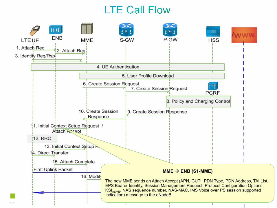
MME à ENB (S1-MME)
The new MME sends an Attach Accept (APN, GUTI, PDN Type, PDN Address, TAI List, EPS Bearer Identity, Session Management Request, Protocol Configuration Options, KSIASME, NAS sequence number, NAS-MAC, IMS Voice over PS session supported Indication) message to the eNodeB

82 © 2013 Cisco and/or its affiliates. All rights reserved.
Ue ßà ENB • The eNodeB sends the RRC Connection Reconfiguration
message including the EPS Radio Bearer Identity to the UE, and the Attach Accept message will be sent along to the UE.
• The UE shall store the QoS Negotiated, Radio Priority, Packet
Flow Id and TI, which it received in the Session Management The APN is provided to the UE to notify it of the APN for which
the activated default bearer is associated.

83 © 2013 Cisco and/or its affiliates. All rights reserved.
ENB à MME (S1-MME)
The eNodeB sends the Initial Context Response message to the new MME. This Initial Context Response message includes the TEID of the eNodeB and the address of the eNodeB used for downlink traffic on the S1_U reference point.
84 © 2013 Cisco and/or its affiliates. All rights reserved.
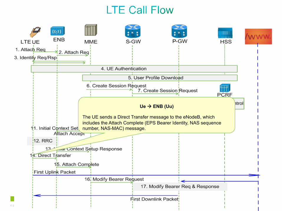
Ue à ENB (Uu)
The UE sends a Direct Transfer message to the eNodeB, which includes the Attach Complete (EPS Bearer Identity, NAS sequence number, NAS-MAC) message.

85 © 2013 Cisco and/or its affiliates. All rights reserved.
ENB à MME
The eNodeB forwards the Attach Complete message to the new MME

86 © 2013 Cisco and/or its affiliates. All rights reserved.
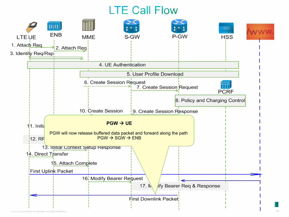
Ue à Internet
Mobile device now can send uplink data to the internet since it has obtain the necessary data from the network i.e Mobile IP address.
Internet à Ue Content from the Internet is buffered on the PGW
until Modify bearer has completed
87 © 2013 Cisco and/or its affiliates. All rights reserved.
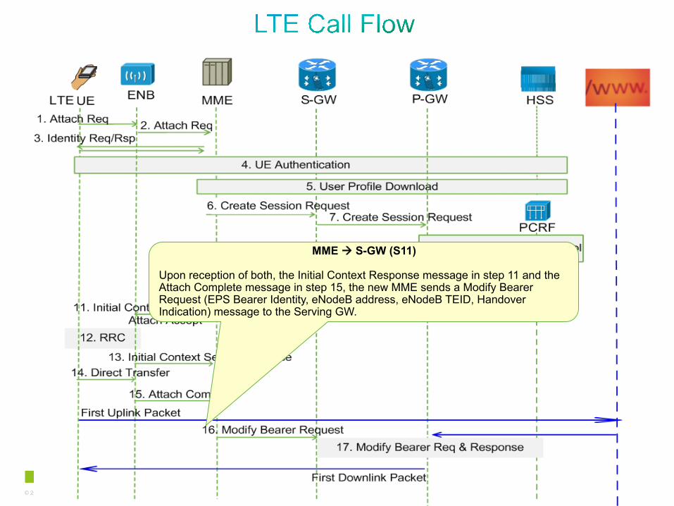
MME à S-GW (S11)
Upon reception of both, the Initial Context Response message in step 11 and the Attach Complete message in step 15, the new MME sends a Modify Bearer Request (EPS Bearer Identity, eNodeB address, eNodeB TEID, Handover Indication) message to the Serving GW.
88 © 2013 Cisco and/or its affiliates. All rights reserved.
SGW – PGW – PCRF The PDN GW acknowledges by sending Modify Bearer Response to the Serving GW. The Serving GW acknowledges by sending Modify Bearer Response (EPS Bearer Identity) message to the new MME
89 © 2013 Cisco and/or its affiliates. All rights reserved.
PGW à UE
PGW will now release buffered data packet and forward along the path PGW à SGW à ENB

90 © 2013 Cisco and/or its affiliates. All rights reserved.
• Reference 1 https://supportforums.cisco.com/community/netpro/wireless-mobility
• Reference 2 http://www.cisco.com/en/US/products/ps12543/index.html
• Reference 3
http://www.3gpp.org/
• Support pages:
• http://www.cisco.com/en/US/products/hw/wireless/products.html
• http://www.cisco.com/en/US/products/ps11072/products_installation_and_configuration_guides_list.html
91 © 2013 Cisco and/or its affiliates. All rights reserved.
What is predicted this year to exceed the world’s population?
92 © 2013 Cisco and/or its affiliates. All rights reserved.
Expert responding some of your questions verbally. Use the Q&A panel to continue asking your questions

93 © 2013 Cisco and/or its affiliates. All rights reserved.
Those who fill out the Evaluation Survey will enter a raffle to win:
$50 Amazon Gift Card
To complete the evaluation, please click on link provided in the chat or in the pop-up once the event is closed.
94 © 2013 Cisco and/or its affiliates. All rights reserved.
You can watch the video or read the Q&A 5 business days after the event at https://supportforums.cisco.com/community/netpro/ask-the-expert/webcasts

95 © 2013 Cisco and/or its affiliates. All rights reserved.
If you have additional questions, you can ask them to Deepak. He will be answering from March 5th to March 15th. https://supportforums.cisco.com/thread/2202208

96 © 2013 Cisco and/or its affiliates. All rights reserved.
Tuesday, April 2, 2013 8:00 a.m. Pacific Time 11:00 a.m. New York 5:00 p.m. Paris
Join Cisco Expert:
Tejas Shah During the live event you will get an overview of Cisco Prime
Infrastructure with Cisco expert Tejas Shah. He will explain common concepts and terminology, how to use configuration templates, and how to use the Cisco Prime Infrastructure to troubleshoot and manage your converged wireless and wired network. He will also do a live demo.
Register Now
http://tinyurl.com/cscwebevents
Configure and Troubleshoot Wired and Wireless Networks Using Cisco Prime Infrastructure

97 © 2013 Cisco and/or its affiliates. All rights reserved.
Upcoming Live Webcast in Spanish: March 12, 2013 ASA 8.x: VPN Access and AnyConnect VPN Client Using Self-Signed Certify, Configuration, and Troubleshooting
Register Now for these Local language webcast at: http://tinyurl.com/cscwebevents
Upcoming Live Webcast in Portuguese: April 16, 2013
Multicast VPN Fundamentals, Configuration, and Troubleshooting
Upcoming Live Webcast in Russian: March 19, 2013
Virtual Switching System and Its Implementation on Cisco Catalyst 4500 and 6500 Platforms

98 © 2013 Cisco and/or its affiliates. All rights reserved.
Topic: Securing Today's Collaboration Environments
Cisco Experts: Akhil Behl and Jason Burns Learn and ask questions about how to apply security to collaboration platforms and environments.
Ends March 8th
Join the discussion for these Ask The Expert Events at: http://tinyurl.com/cscate-events
Topic: Deploying, Configuring and Troubleshooting Cisco WebEx Meetings Server
Cisco Experts: Srdjan Ciric
Learn and ask questions regarding deployment, configuration and troubleshooting the Cisco WebEx Meetings Server.
Ends March 8th

© 2013 Cisco and/or its affiliates. All rights reserved. 99
If you speak Spanish, Portuguese, Japanese, Polish or Russian, we invite you to ask your questions and collaborate in your language: • Spanish à https://supportforums.cisco.com/community/spanish
• Portuguese à https://supportforums.cisco.com/community/portuguese
• Japanese à https://supportforums.cisco.com/community/csc-japan
• Polish à https://supportforums.cisco.com/community/etc/netpro-polska
• Russian à https://supportforums.cisco.com/community/russian

© 2013 Cisco and/or its affiliates. All rights reserved. 100
https://supportforms.cisco.com http://www.facebook.com/CiscoSupportCommunity
http://twitter.com/#!/cisco_support
http://www.youtube.com/user/ciscosupportchannel
https://plus.google.com/110418616513822966153?prsrc=3#110418616513822966153/posts
http://www.linkedin.com/groups/CSC-Cisco-Support-Community-3210019
Newsletter Subscription: https://tools.cisco.com/gdrp/coiga/showsurvey.do?surveyCode=589&keyCode=146298_2&PHYSICAL%20FULFILLMENT%20Y/N=NO&SUBSCRIPTION%20CENTER=YES
http://itunes.apple.com/us/app/cisco-technical-support/id398104252?mt=8
https://play.google.com/store/apps/details?id=com.cisco.swtg_android

101 © 2013 Cisco and/or its affiliates. All rights reserved.
A. Smartphones will ‘outnumber humans this year’
B. Mobile internet devices will ‘outnumber humans this year’
C. Tablets will ‘outnumber humans this year’
What is predicted this year to exceed the world’s population?
Correct Answer B. A report from Cisco said the number of smartphones, tablets, laptops and internet-capable phones will outnumber humans in 2013. That report said the amount of internet-connected devices will exceed 7 billion — the world’s current population. Mobile video already makes up more than half of the data transmitted worldwide. By 2017, it will make up two-thirds of it. Smartphones make up 92 percent of global mobile data traffic, despite only 18 percent of the handsets in use globally.

Thank You for Your Time
Please Take a Moment to Complete the Evaluation

Thank you.