cisco security mars hardware installation and maintenance
TRANSCRIPT

Americas HeadquartersCisco Systems, Inc.170 West Tasman DriveSan Jose, CA 95134-1706 USAhttp://www.cisco.comTel: 408 526-4000
800 553-NETS (6387)Fax: 408 527-0883
Cisco Security MARS Hardware Installation and Maintenance GuideRelease 6.x September 2008
Customer Order Number: Text Part Number: OL-16535-01

THE SPECIFICATIONS AND INFORMATION REGARDING THE PRODUCTS IN THIS MANUAL ARE SUBJECT TO CHANGE WITHOUT NOTICE. ALL STATEMENTS, INFORMATION, AND RECOMMENDATIONS IN THIS MANUAL ARE BELIEVED TO BE ACCURATE BUT ARE PRESENTED WITHOUT WARRANTY OF ANY KIND, EXPRESS OR IMPLIED. USERS MUST TAKE FULL RESPONSIBILITY FOR THEIR APPLICATION OF ANY PRODUCTS.
THE SOFTWARE LICENSE AND LIMITED WARRANTY FOR THE ACCOMPANYING PRODUCT ARE SET FORTH IN THE INFORMATION PACKET THAT SHIPPED WITH THE PRODUCT AND ARE INCORPORATED HEREIN BY THIS REFERENCE. IF YOU ARE UNABLE TO LOCATE THE SOFTWARE LICENSE OR LIMITED WARRANTY, CONTACT YOUR CISCO REPRESENTATIVE FOR A COPY.
The Cisco implementation of TCP header compression is an adaptation of a program developed by the University of California, Berkeley (UCB) as part of UCB’s public domain version of the UNIX operating system. All rights reserved. Copyright © 1981, Regents of the University of California.
NOTWITHSTANDING ANY OTHER WARRANTY HEREIN, ALL DOCUMENT FILES AND SOFTWARE OF THESE SUPPLIERS ARE PROVIDED “AS IS” WITH ALL FAULTS. CISCO AND THE ABOVE-NAMED SUPPLIERS DISCLAIM ALL WARRANTIES, EXPRESSED OR IMPLIED, INCLUDING, WITHOUT LIMITATION, THOSE OF MERCHANTABILITY, FITNESS FOR A PARTICULAR PURPOSE AND NONINFRINGEMENT OR ARISING FROM A COURSE OF DEALING, USAGE, OR TRADE PRACTICE.
IN NO EVENT SHALL CISCO OR ITS SUPPLIERS BE LIABLE FOR ANY INDIRECT, SPECIAL, CONSEQUENTIAL, OR INCIDENTAL DAMAGES, INCLUDING, WITHOUT LIMITATION, LOST PROFITS OR LOSS OR DAMAGE TO DATA ARISING OUT OF THE USE OR INABILITY TO USE THIS MANUAL, EVEN IF CISCO OR ITS SUPPLIERS HAVE BEEN ADVISED OF THE POSSIBILITY OF SUCH DAMAGES.
Any Internet Protocol (IP) addresses used in this document are not intended to be actual addresses. Any examples, command display output, and figures included in the document are shown for illustrative purposes only. Any use of actual IP addresses in illustrative content is unintentional and coincidental.
Cisco Security MARS Hardware Installation and Maintenance Guide Copyright © 2008 Cisco Systems, Inc. All rights reserved.
CCVP, the Cisco logo, and Welcome to the Human Network are trademarks of Cisco Systems, Inc.; Changing the Way We Work, Live, Play, and Learn is a service mark of Cisco Systems, Inc.; and Access Registrar, Aironet, Catalyst, CCDA, CCDP, CCIE, CCIP, CCNA, CCNP, CCSP, Cisco, the Cisco Certified Internetwork Expert logo, Cisco IOS, Cisco Press, Cisco Systems, Cisco Systems Capital, the Cisco Systems logo, Cisco Unity, Enterprise/Solver, EtherChannel, EtherFast, EtherSwitch, Fast Step, Follow Me Browsing, FormShare, GigaDrive, HomeLink, Internet Quotient, IOS, iPhone, IP/TV, iQ Expertise, the iQ logo, iQ Net Readiness Scorecard, iQuick Study, LightStream, Linksys, MeetingPlace, MGX, Networkers, Networking Academy, Network Registrar, PIX, ProConnect, ScriptShare, SMARTnet, StackWise, The Fastest Way to Increase Your Internet Quotient, and TransPath are registered trademarks of Cisco Systems, Inc. and/or its affiliates in the United States and certain other countries.
All other trademarks mentioned in this document or Website are the property of their respective owners. The use of the word partner does not imply a partnership relationship between Cisco and any other company. (0711R)
OL-16535-01
C O N T E N T S
Preface vii
Audience i-vii
Organization i-vii
Conventions i-viii
Warning Definition i-ix
Related Documentation i-xiii
Obtaining Documentation, Obtaining Support, and Security Guidelines i-xiv
C H A P T E R 1 Physical Descriptions—MARS 25R, 25, 55, 110R, 110, 210, GC2R, and GC2 1-1
Part Numbers, License Key, Serial Numbers, and Warranty 1-1
Part Numbers 1-1
License Key 1-2
Evaluation (Demo) License Key 1-2
Serial Numbers 1-3
Limited Warranty 1-3
Technical Specifications for MARS 25R, 25, and 55 1-3
Technical Specifications for MARS 110R, 110, 210, GC2, and GC2R 1-4
Removing and Replacing the Front Bezel 1-6
MARS 25R and 25 Front and Back Panels 1-8
Front Panel Features—MARS 25 and 25R 1-8
Control Panel Description—MARS 25R and 25 1-8
Control Panel LED Descriptions—MARS 25R and 25 1-9
Back Panel Features—MARS 25R and 25 1-9
MARS 55 Front and Back Panels 1-9
Front Panel Features—MARS 55 1-10
Control Panel Description—MARS 55 1-11
Control Panel LED Descriptions—MARS 55 1-11
Back Panel Features—MARS 55 1-12
MARS 110R, 110, 210, GC2R, and GC2 Front and Back Panels 1-12
Front Panel Features—MARS 110R, 110, 210, GC2R, and GC2 1-12
Control Panel Description—MARS 110R, 110, 210, GC2R, and GC2 1-13
Control Panel LED Descriptions—MARS 110R, 110, 210, GC2R, and GC2 1-15
Back Panel Features—MARS 110R, 110, 210, GC2R, and GC2 1-17
Hard Drive Slot Number Maps 1-18
iiiCisco Security MARS Hardware Installation and Maintenance Guide
Contents
Power Supplies 1-19
MARS 110R, 110, 210, GC2R, and GC2 Power Supply 1-20
AC Power Source Requirements 1-21
Power Supply LED Description 1-21
Checking Power Supply Operational Status 1-22
MARS 25R, 25, and 55 Power Supply 1-22
AC Power Source Requirements 1-23
Connector Descriptions 1-23
C H A P T E R 2 Physical Descriptions—MARS 20R, 20, 50, 100E, 100, 200, GCm, and GC 2-1
Part Numbers, License Key, Serial Numbers, and Warranty 2-1
Part Numbers 2-1
Serial Numbers 2-2
License Key 2-2
Limited Warranty 2-3
Technical Specifications 2-3
MARS 20R and 20 Front and Back Panels 2-4
Front Panel Features—MARS 20R and 20 2-4
Back Panel Features—MARS 20R and MARS 20 2-5
MARS 50 Front and Back Panels 2-5
Front Panel Features—MARS 50 2-6
Back Panel Features—MARS 50 2-6
MARS 100E and 100 Front and Back Panels 2-7
Front Panel Features—MARS 100E and 100 2-7
Back Panel Features—MARS 100E and 100 2-7
MARS 200, GCm, and GC Front and Back Panels 2-8
Front Panel Features—MARS 200, GCm, and GC 2-8
Back Panel Features—MARS 200, GCm, and GC 2-9
Connector Descriptions 2-10
DB-9 Serial Port 2-11
Hard Drive Slot Number Maps 2-12
Hard Drive Layout—MARS 100E and 100 2-12
Hard Drive Layout—MARS 200, GCm, and GC 2-13
C H A P T E R 3 Preparing for Installation 3-1
Safety 3-1
Warnings and Cautions 3-1
General Precautions 3-3
ivCisco Security MARS Hardware Installation and Maintenance Guide
OL-16535-01
Contents
Maintaining Safety with Electricity 3-4
Protecting Against Electrostatic Discharge 3-5
Preventing EMI 3-5
Preparing Your Site for Installation 3-5
Environmental 3-5
Choosing a Site for Installation 3-7
Grounding the System 3-7
Creating a Safe Environment 3-7
AC Power 3-8
Cabling 3-8
Inline Filter for the Modem 3-8
Precautions for Rack-Mounting 3-8
Precautions for Products with Modems, Telecommunications, or Local Area Network Options 3-9
Required Tools and Equipment 3-9
Packaging Contents Checklist 3-9
C H A P T E R 4 Installing the Appliance 4-1
Installation Quick Reference 4-1
Installing the MARS Appliance in a Rack 4-2
Rack-Mounting MARS Appliances 25R, 25, 55, 110R, 110, 210, GC2R, and GC2 4-4
Installing the Chassis Handles 4-4
Basic Rail Rack-Mount Installation 4-5
Basic Rail Rack-Mount Removal 4-5
Rack-Mounting MARS Appliances 20, 50, 100, 100e, 200, GC, and GCM 4-6
Connecting to the AC Power Source 4-9
Connecting Cables 4-10
Powering on the Appliance and Verifying Hardware Operation 4-10
What To Do Next 4-11
C H A P T E R 5 Hardware Maintenance Tasks—MARS 55, 110R, 110, 210, GC2R, and GC2 5-1
Field Replaceable Units 5-1
Removing and Replacing the Front Bezel 5-2
Removing the Chassis Cover 5-3
Replacing the RAID Battery Backup Unit 5-4
Procedure to Replace the Raid Battery Backup Unit 5-5
Replacing the System Battery 5-7
Hard Drive Troubleshooting and Replacement 5-8
Hard Drive Status LEDs 5-8
vCisco Security MARS Hardware Installation and Maintenance Guide
OL-16535-01
Contents
Partition Checking 5-9
Overview of RAID Subsystem 5-9
Hotswapping Hard Drives 5-10
Failed Hard Drive Alert 5-11
Viewing RAID Array Status with the raidstatus CLI Command 5-11
Hard Drive Slot Number Diagrams 5-15
Procedure to Hotswap a Hard Drive 5-16
Hotswap CLI Example 5-18
Replacing a Hard Drive in the Hard Drive Carrier 5-20
Hot-swapping a Power Supply Unit 5-21
Installing the Inline Modem Filter 5-22
Diagnostic Beep Codes 5-22
Safety Information 5-22
Intended Application Uses 5-23
Equipment Handling Practices 5-23
Power and Electrical Warnings 5-23
Power Cord Warnings 5-24
System Access Warnings 5-24
Rack Mount Warnings 5-25
Electrostatic Discharge (ESD) 5-25
Battery Replacement 5-25
Cooling and Airflow 5-26
Laser Peripherals or Devices 5-26
C H A P T E R 6 Hardware Maintenance Tasks—MARS 100E, 100, 200, GCM, and GC 6-1
Replacing the Lithium Cell CMOS Battery 6-1
Hard Drive Troubleshooting and Replacement 6-1
Hard Drive Status Lights 6-2
Partition Checking 6-2
Hotswapping Hard Drives 6-2
Overview of MARS RAID 10 Subsystem 6-2
RAID Procedures for MARS Appliances 100E, 100, 200, GCM, and GC 6-3
Correlating Hard Drive Slots to RAIDSTATUS Command Physical Port Numbers 6-6
Hotswap Procedure To Remove and Add a Hard Drive 6-8
Hotswap CLI Example 6-9
Procedures for the MARS RAID Utility 6-10
IN D E X
viCisco Security MARS Hardware Installation and Maintenance Guide
OL-16535-01

Preface
Revised: September 8, 2008, OL-16535-01This manual describes how to physically install and prepare or configuration the Cisco Security Monitoring, Analysis, and Response System Appliance, Release 6.x (MARS Appliance, or MARS).
AudienceThis manual is for system administrators who install and configure internetworking equipment.
Warning Only trained and qualified personnel should install, replace, or service this equipment.
OrganizationThis manual consists of the following chapters and appendixes:
• Chapter 1, “Physical Descriptions—MARS 25R, 25, 55, 110R, 110, 210, GC2R, and GC2,” provides technical specifications and part numbers for MARS second generation hardware with front and back panel diagrams for each appliance.
• Chapter 2, “Physical Descriptions—MARS 20R, 20, 50, 100E, 100, 200, GCm, and GC,” provides technical specifications and part numbers for MARS first generation hardware with front and back panel diagrams for each appliance.
• Chapter 3, “Preparing for Installation,” presents safety information and site preparation requirements.
• Chapter 4, “Installing the Appliance,” describes how to rack mount the MARS Appliance.
• Chapter 5, “Hardware Maintenance Tasks—MARS 55, 110R, 110, 210, GC2R, and GC2,” provides procedures for replacing and troubleshooting MARS Field Replaceable Units (FRUs) such as hard disk drives (HDDs) and the RAID backup battery.
• Chapter 6, “Hardware Maintenance Tasks—MARS 100E, 100, 200, GCM, and GC,” provides procedures for replacing and troubleshooting MARS Field Replaceable Units (FRUs) such as hard disk drives (HDDs).
viiCisco Security MARS Hardware Installation and Maintenance Guide
OL-16535-01
PrefaceConventions
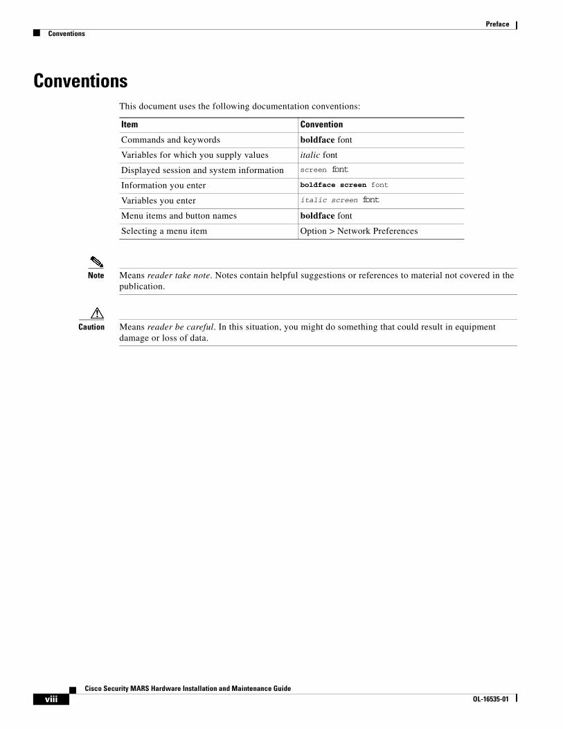
ConventionsThis document uses the following documentation conventions:
Note Means reader take note. Notes contain helpful suggestions or references to material not covered in the publication.
Caution Means reader be careful. In this situation, you might do something that could result in equipment damage or loss of data.
Item Convention
Commands and keywords boldface font
Variables for which you supply values italic font
Displayed session and system information screen font
Information you enter boldface screen font
Variables you enter italic screen font
Menu items and button names boldface font
Selecting a menu item Option > Network Preferences
viiiCisco Security MARS Hardware Installation and Maintenance Guide
OL-16535-01

PrefaceConventions
Warning Definition
Warning IMPORTANT SAFETY INSTRUCTIONS
This warning symbol means danger. You are in a situation that could cause bodily injury. Before you work on any equipment, be aware of the hazards involved with electrical circuitry and be familiar with standard practices for preventing accidents. To see translations of the warnings that appear in this publication, refer to the translated safety warnings that accompanied this device.
Note: SAVE THESE INSTRUCTIONS
Note: This documentation is to be used in conjunction with the specific product installation guide that shipped with the product. Please refer to the Installation Guide, Configuration Guide, or other enclosed additional documentation for further details.
Waarschuwing BELANGRIJKE VEILIGHEIDSINSTRUCTIES
Dit waarschuwingssymbool betekent gevaar. U verkeert in een situatie die lichamelijk letsel kan veroorzaken. Voordat u aan enige apparatuur gaat werken, dient u zich bewust te zijn van de bij elektrische schakelingen betrokken risico's en dient u op de hoogte te zijn van de standaard praktijken om ongelukken te voorkomen. Voor een vertaling van de waarschuwingen die in deze publicatie verschijnen, dient u de vertaalde veiligheidswaarschuwingen te raadplegen die bij dit apparaat worden geleverd.
Opmerking BEWAAR DEZE INSTRUCTIES.
Opmerking Deze documentatie dient gebruikt te worden in combinatie met de installatiehandleiding voor het specifieke product die bij het product wordt geleverd. Raadpleeg de installatiehandleiding, configuratiehandleiding of andere verdere ingesloten documentatie voor meer informatie.
Varoitus TÄRKEITÄ TURVALLISUUTEEN LIITTYVIÄ OHJEITA
Tämä varoitusmerkki merkitsee vaaraa. Olet tilanteessa, joka voi johtaa ruumiinvammaan. Ennen kuin työskentelet minkään laitteiston parissa, ota selvää sähkökytkentöihin liittyvistä vaaroista ja tavanomaisista onnettomuuksien ehkäisykeinoista. Tässä asiakirjassa esitettyjen varoitusten käännökset löydät laitteen mukana toimitetuista ohjeista.
Huomautus SÄILYTÄ NÄMÄ OHJEET
Huomautus Tämä asiakirja on tarkoitettu käytettäväksi yhdessä tuotteen mukana tulleen asennusoppaan kanssa. Katso lisätietoja asennusoppaasta, kokoonpano-oppaasta ja muista mukana toimitetuista asiakirjoista.
ixCisco Security MARS Hardware Installation and Maintenance Guide
OL-16535-01
PrefaceConventions
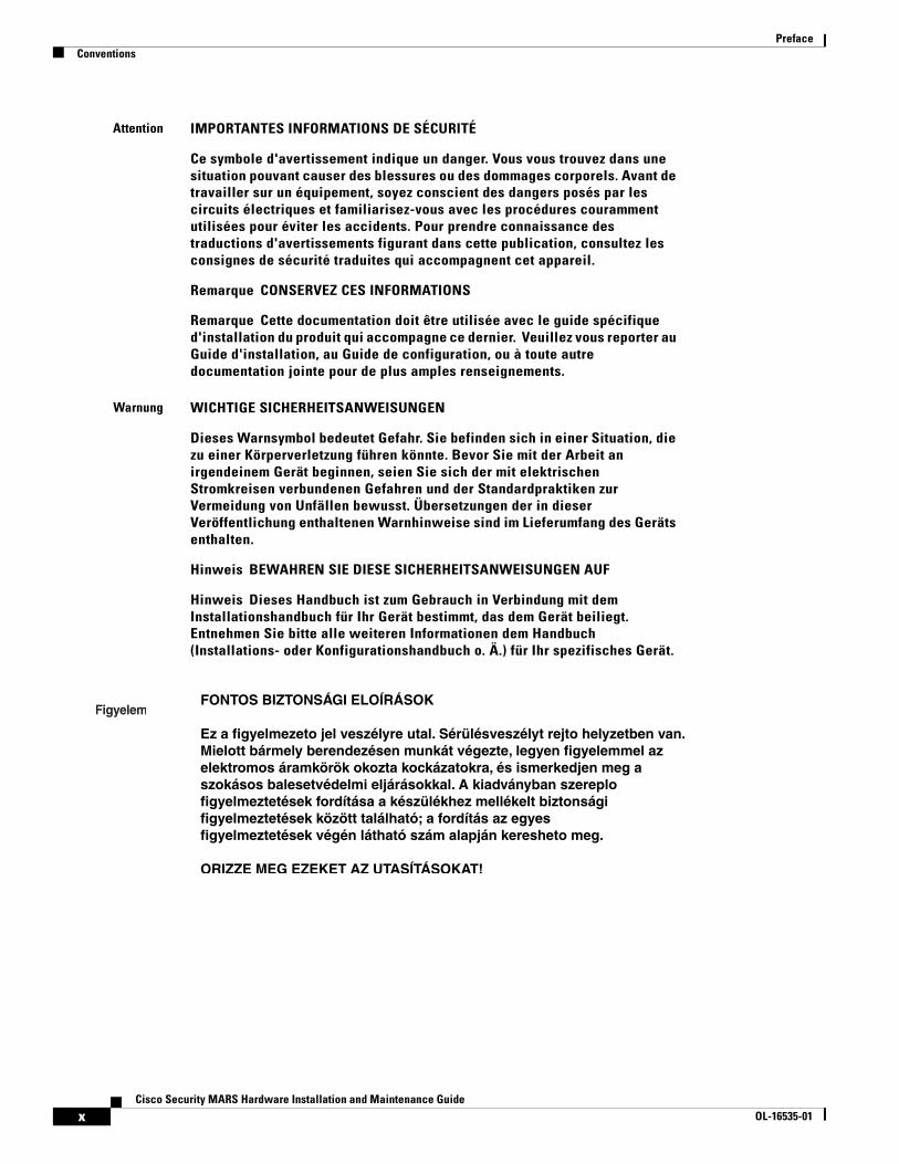
Attention IMPORTANTES INFORMATIONS DE SÉCURITÉ
Ce symbole d'avertissement indique un danger. Vous vous trouvez dans une situation pouvant causer des blessures ou des dommages corporels. Avant de travailler sur un équipement, soyez conscient des dangers posés par les circuits électriques et familiarisez-vous avec les procédures couramment utilisées pour éviter les accidents. Pour prendre connaissance des traductions d'avertissements figurant dans cette publication, consultez les consignes de sécurité traduites qui accompagnent cet appareil.
Remarque CONSERVEZ CES INFORMATIONS
Remarque Cette documentation doit être utilisée avec le guide spécifique d'installation du produit qui accompagne ce dernier. Veuillez vous reporter au Guide d'installation, au Guide de configuration, ou à toute autre documentation jointe pour de plus amples renseignements.
Warnung WICHTIGE SICHERHEITSANWEISUNGEN
Dieses Warnsymbol bedeutet Gefahr. Sie befinden sich in einer Situation, die zu einer Körperverletzung führen könnte. Bevor Sie mit der Arbeit an irgendeinem Gerät beginnen, seien Sie sich der mit elektrischen Stromkreisen verbundenen Gefahren und der Standardpraktiken zur Vermeidung von Unfällen bewusst. Übersetzungen der in dieser Veröffentlichung enthaltenen Warnhinweise sind im Lieferumfang des Geräts enthalten.
Hinweis BEWAHREN SIE DIESE SICHERHEITSANWEISUNGEN AUF
Hinweis Dieses Handbuch ist zum Gebrauch in Verbindung mit dem Installationshandbuch für Ihr Gerät bestimmt, das dem Gerät beiliegt. Entnehmen Sie bitte alle weiteren Informationen dem Handbuch (Installations- oder Konfigurationshandbuch o. Ä.) für Ihr spezifisches Gerät.
xCisco Security MARS Hardware Installation and Maintenance Guide
OL-16535-01

PrefaceConventions
Avvertenza IMPORTANTI ISTRUZIONI SULLA SICUREZZA
Questo simbolo di avvertenza indica un pericolo. La situazione potrebbe causare infortuni alle persone. Prima di intervenire su qualsiasi apparecchiatura, occorre essere al corrente dei pericoli relativi ai circuiti elettrici e conoscere le procedure standard per la prevenzione di incidenti. Per le traduzioni delle avvertenze riportate in questo documento, vedere le avvertenze di sicurezza che accompagnano questo dispositivo.
Nota CONSERVARE QUESTE ISTRUZIONI
Nota La presente documentazione va usata congiuntamente alla guida di installazione specifica spedita con il prodotto. Per maggiori informazioni, consultare la Guida all'installazione, la Guida alla configurazione o altra documentazione acclusa.
Advarsel VIKTIGE SIKKERHETSINSTRUKSJONER
Dette varselssymbolet betyr fare. Du befinner deg i en situasjon som kan forårsake personskade. Før du utfører arbeid med utstyret, bør du være oppmerksom på farene som er forbundet med elektriske kretssystemer, og du bør være kjent med vanlig praksis for å unngå ulykker. For å se oversettelser av advarslene i denne publikasjonen, se de oversatte sikkerhetsvarslene som følger med denne enheten.
Merk TA VARE PÅ DISSE INSTRUKSJONENE
Merk Denne dokumentasjonen skal brukes i forbindelse med den spesifikke installasjonsveiledningen som fulgte med produktet. Vennligst se installasjonsveiledningen, konfigureringsveiledningen eller annen vedlagt tilleggsdokumentasjon for detaljer.
Aviso INSTRUÇÕES IMPORTANTES DE SEGURANÇA
Este símbolo de aviso significa perigo. O utilizador encontra-se numa situação que poderá ser causadora de lesões corporais. Antes de iniciar a utilização de qualquer equipamento, tenha em atenção os perigos envolvidos no manuseamento de circuitos eléctricos e familiarize-se com as práticas habituais de prevenção de acidentes. Para ver traduções dos avisos incluídos nesta publicação, consulte os avisos de segurança traduzidos que acompanham este dispositivo.
Nota GUARDE ESTAS INSTRUÇÕES
Nota Esta documentação destina-se a ser utilizada em conjunto com o manual de instalação incluído com o produto específico. Consulte o manual de instalação, o manual de configuração ou outra documentação adicional inclusa, para obter mais informações.
xiCisco Security MARS Hardware Installation and Maintenance Guide
OL-16535-01
PrefaceConventions
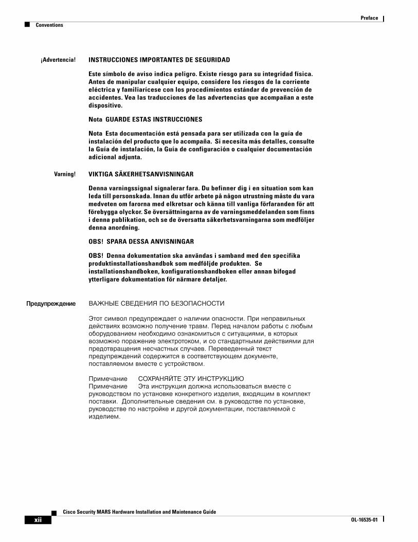
¡Advertencia! INSTRUCCIONES IMPORTANTES DE SEGURIDAD
Este símbolo de aviso indica peligro. Existe riesgo para su integridad física. Antes de manipular cualquier equipo, considere los riesgos de la corriente eléctrica y familiarícese con los procedimientos estándar de prevención de accidentes. Vea las traducciones de las advertencias que acompañan a este dispositivo.
Nota GUARDE ESTAS INSTRUCCIONES
Nota Esta documentación está pensada para ser utilizada con la guía de instalación del producto que lo acompaña. Si necesita más detalles, consulte la Guía de instalación, la Guía de configuración o cualquier documentación adicional adjunta.
Varning! VIKTIGA SÄKERHETSANVISNINGAR
Denna varningssignal signalerar fara. Du befinner dig i en situation som kan leda till personskada. Innan du utför arbete på någon utrustning måste du vara medveten om farorna med elkretsar och känna till vanliga förfaranden för att förebygga olyckor. Se översättningarna av de varningsmeddelanden som finns i denna publikation, och se de översatta säkerhetsvarningarna som medföljer denna anordning.
OBS! SPARA DESSA ANVISNINGAR
OBS! Denna dokumentation ska användas i samband med den specifika produktinstallationshandbok som medföljde produkten. Se installationshandboken, konfigurationshandboken eller annan bifogad ytterligare dokumentation för närmare detaljer.
xiiCisco Security MARS Hardware Installation and Maintenance Guide
OL-16535-01
PrefaceRelated Documentation
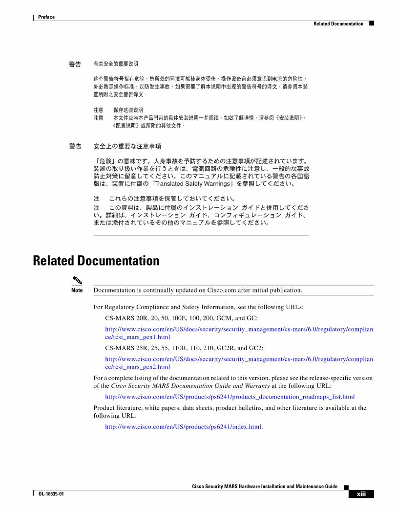
Related Documentation
Note Documentation is continually updated on Cisco.com after initial publication.
For Regulatory Compliance and Safety Information, see the following URLs:
CS-MARS 20R, 20, 50, 100E, 100, 200, GCM, and GC:
http://www.cisco.com/en/US/docs/security/security_management/cs-mars/6.0/regulatory/compliance/rcsi_mars_gen1.html
CS-MARS 25R, 25, 55, 110R, 110, 210, GC2R, and GC2:
http://www.cisco.com/en/US/docs/security/security_management/cs-mars/6.0/regulatory/compliance/rcsi_mars_gen2.html
For a complete listing of the documentation related to this version, please see the release-specific version of the Cisco Security MARS Documentation Guide and Warranty at the following URL:
http://www.cisco.com/en/US/products/ps6241/products_documentation_roadmaps_list.html
Product literature, white papers, data sheets, product bulletins, and other literature is available at the following URL:
http://www.cisco.com/en/US/products/ps6241/index.html.
xiiiCisco Security MARS Hardware Installation and Maintenance Guide
OL-16535-01
PrefaceObtaining Documentation, Obtaining Support, and Security Guidelines
Obtaining Documentation, Obtaining Support, and Security Guidelines
For information on obtaining documentation, obtaining support, providing documentation feedback, security guidelines, and also recommended aliases and general Cisco documents, see the monthly What’s New in Cisco Product Documentation, which also lists all new and revised Cisco technical documentation, at:
http://www.cisco.com/en/US/docs/general/whatsnew/whatsnew.html
xivCisco Security MARS Hardware Installation and Maintenance Guide
OL-16535-01

Cisco Security MOL-16535-01
C H A P T E R 1
Physical Descriptions—MARS 25R, 25, 55, 110R, 110, 210, GC2R, and GC2The Cisco Security MARS 25R, 25, 55, 110R, 110, 210, GC2R, and GC2 appliances are built with the second generation of MARS hardware, and operate with only MARS software versions 5.x and 6.x.
This section consists of the following subsections:
• Part Numbers, License Key, Serial Numbers, and Warranty, page 1-1
• Technical Specifications for MARS 25R, 25, and 55, page 1-3
• Technical Specifications for MARS 110R, 110, 210, GC2, and GC2R, page 1-4
• Removing and Replacing the Front Bezel, page 1-6
• MARS 25R and 25 Front and Back Panels, page 1-8
• MARS 55 Front and Back Panels, page 1-9
• MARS 110R, 110, 210, GC2R, and GC2 Front and Back Panels, page 1-12
• Hard Drive Slot Number Maps, page 1-18
• Power Supplies, page 1-19
• Connector Descriptions, page 1-23
Part Numbers, License Key, Serial Numbers, and WarrantyThis section contains the following subsections:
• Part Numbers, page 1-1
• License Key, page 1-2
• Evaluation (Demo) License Key, page 1-2
• Serial Numbers, page 1-3
• Limited Warranty, page 1-3
Part NumbersThe part numbers of Cisco Security MARS Appliances and the Field Replaceable Units (FRUs) that operate with software releases 5.x and 6.x are as follows:
1-1ARS Hardware Installation and Maintenance Guide

Chapter 1 Physical Descriptions—MARS 25R, 25, 55, 110R, 110, 210, GC2R, and GC2Part Numbers, License Key, Serial Numbers, and Warranty
Local Controller Appliances
• CS-MARS-25R-K9
• CS-MARS-25-K9
• CS-MARS-55-K9
• CS-MARS-110R-K9
• CS-MARS-110-K9
• CS-MARS-210-K9
Global Controller Appliances
• CS-MARS-GC2R-K9
• CS-MARS-GC2-K9
License Key See the section, Licensing the Appliance, in the Cisco Security MARS Initial Configuration and Upgrade Guide, 6.X.
Evaluation (Demo) License KeyIn circumstances where you are evaluating equipment on loan from Cisco, you can generate your own temporary license key.
To obtain a 60-day demo license key, complete the registrant information form at the following URL (you must log in with your Cisco CCO credentials):
https://tools.cisco.com/SWIFT/Licensing/PrivateRegistrationServlet?FormId=240
Your Cisco Demo License key will be sent within 1 hour to the email address specified in the form.
FRU Description FRU Part Number
SR2500 (Driskill 2) 750 Watt Power Supply Module (MARS 110R, 110, 210, GC2R, GC)
CS-MARS-D750-PS =
500 GB SATA-IO Hard Disk Drive (MARS 55)
CS-MARS-H500-HD =
500 GB SATA-IO Hard Disk Drive (MARS 110R, 110)
CS-MARS-S500-HD =
750 GB SATA-IO Hard Disk Drive (MARS 210, GC2R, GC)
CS-MARS-S750-HD =
RAID Controller Back-Up Battery Unit (MARS 110R, 110, 210, GC2R, GC)
CS-MARS-X10-BB =
Rack-mount Kit (MARS 25R, 25, 55, 110R, 110, 210, GC2R, GC)
CS-MARS-X10-RAIL=
1-2Cisco Security MARS Hardware Installation and Maintenance Guide
OL-16535-01
Chapter 1 Physical Descriptions—MARS 25R, 25, 55, 110R, 110, 210, GC2R, and GC2Technical Specifications for MARS 25R, 25, and 55
Serial Numbers If you have difficulty identifying or physically locating the serial number sticker on your appliance chassis, use the Cisco Product Identification Tool at the following URL:
http://tools.cisco.com/Support/CPI/index.do
You must be registered with Cisco Systems Customer Connection Online to access this tool. If you are not registered, you can register at the following URL:
http://tools.cisco.com/RPF/register/register.do
The chassis, hard drive, and power supply serial numbers are also reported in the show inventory CLI command.
Limited WarrantyFor the warranty, disclaimer of warranty, and end user license agreement that applies to your product, refer to the version of the Cisco Security MARS Documentation Guide and Warranty that shipped with your product. You can view the latest versions of this document at:
http://www.cisco.com/en/US/products/ps6241/products_documentation_roadmaps_list.html
Technical Specifications for MARS 25R, 25, and 55 Table 1-1 summarizes accessible chassis and component descriptions. Table 1-2 summarizes environmental and electrical descriptions.
Table 1-1 Technical Specifications—MARS 25R, 25, and 55
Chassis Feature MARS 25R and MARS 25 MARS 55
Maximum Weight
15 kg (33 lbs) 18.14 kg (40lbs)
Dimensions Rack (1U)
Height: 4.24 cm (1.67 in)
Width w/o rails: 43.00 cm (16.93 in)
Depth 50.80 cm (20 in)
Rack (1U)
Height: 4.24 cm (1.67 in)
Width w/o rails: 43.00 cm (16.93 in)
Depth 64.80 cm (25.51 in)
Power Supplies 350W ATX 350W ATX
Integrated Network Controller
NIC 1–Embedded Intel 82573 E/V (Tekoa) 10/100/1000 Gigabit Ethernet Controller
NIC 2–Embedded Intel 82541 PI (Tabor) 10/100/1000 Gigabit Ethernet Controller
NIC 1–Embedded Intel 82573 E/V (Tekoa) 10/100/1000 Gigabit Ethernet Controller
NIC 2–Embedded Intel 82541 PI (Tabor) 10/100/1000 Gigabit Ethernet Controller
Modem US Robotics 56k V.92 Performance Pro Modem (USR802972B-OEM
US Robotics 56k V.92 Performance Pro Modem (USR802972B-OEM
1-3Cisco Security MARS Hardware Installation and Maintenance Guide
OL-16535-01

Chapter 1 Physical Descriptions—MARS 25R, 25, 55, 110R, 110, 210, GC2R, and GC2Technical Specifications for MARS 110R, 110, 210, GC2, and GC2R
Technical Specifications for MARS 110R, 110, 210, GC2, and GC2R
Table 1-3 summarizes accessible chassis and component descriptions; Table 1-4 summarizes environmental and electrical descriptions.
Hard Drive Storage
1x 250GB SATA-IO 3.0 Gps HDD 7200RPM, 16 MB Buffer
500 GB RAID 1 2x 500 SATA-IO 3.0 Gps HDD 7200RPM, 32 MB Buffer
Hot-Swappable Front Accessible
DVD-ROM Slimline optical drive Slimline optical drive
System battery Lithium button cell Lithium button cell
Table 1-2 Environmental Parameters—MARS 25, 25R, and 55
Environmental Parameter MARS 25R, MARS 25, and MARS 55
Temperature range Operating: +10°C to +35°C derated 0.5 °C for every 1,000 ft. (305 m) to a maximum of 10,000 ft. The maximum rate of change not to exceed 10°C per hour
Non-operating: –40° C to +70° C
Humidity (non-operating)
90% relative humidity, Non-condensing at +35°C
System Cooling Requirement
1,194 BTU/hour max. (350W)
Vibration Unpackaged: 5 Hz to 500 Hz, 2.20 g RMS random
Shock Operating: Half sine, 2 g peak, 11 mSec
Unpackaged: Trapezoidal, 25 g, velocity change 136 inches/sec.
Packaged: 18 inches in non-palletized free fall (>= 40 lbs to < 80 lbs)
Acoustic Noise Sound Pressure: 55 dBA (Rack mount) in an idle state at typical office ambient temperatures Sound Power: 7.0 bels in an idle state at typical office ambient temperatures.
Electrostatic discharge (ESD)
Tested to +/-15 kilovolts (kV) with no component damage.
Table 1-1 Technical Specifications—MARS 25R, 25, and 55
Chassis Feature MARS 25R and MARS 25 MARS 55
1-4Cisco Security MARS Hardware Installation and Maintenance Guide
OL-16535-01
Chapter 1 Physical Descriptions—MARS 25R, 25, 55, 110R, 110, 210, GC2R, and GC2Technical Specifications for MARS 110R, 110, 210, GC2, and GC2R
Table 1-3 Technical Specifications—MARS 110R, 110, 210, GC2, and GC2R
Chassis Feature MARS 110R and 110 MARS 210, GC2R, and MARS GC2
Maximum Weight
29.5 kg (65 lbs) Same as 110
Dimensions 2 Rack Units (2U) Height: 87.3 mm (3.44 in)
Width w/o rails: 430 mm (16.93 in) Width with rails: 451.3 mm (17.77 in)
Depth: 704.8 mm (27.75 in)
)
Same as 110
Power Supplies 2 X 750W Redundant (1 + 1) ATX Hot-swappable 100-240 VAC 50-60Hz
Same as 110
Power Consumption
11A maximum @110 VAC 5.5A maximum @ 220 VAC
Same as 110
Integrated Network Controller
Dual Intel 82563 EB 10/100/1000 PHYs supporting Intel I/O Acceleration Technology
Same as 110
PCI NIC Dual Port Intel Pro/1000 PT Network Controller
Same as 110
Modem US Robotics 56k V.92 Performance Pro Modem (USR5610B)
or
US Robotics 56k V.92 Performance Pro Modem (USR802972A-OEM)
Same as 110
Hard Drive Storage
1.5TB RAID 10 6 X 500GB SATA-IO 3.0 Gps HDD 7200 RPM, 16MB Buffer
Hot-swappable Front accessible
2.0 TB1 RAID 10 6 X 750GB SATA-IO 3.0 Gps HDD 7200 RPM, 16 MB Buffer
Hot-swappable Front accessible
1. Although there is a total of 4.5 TB storage, RAID 10 has a maximum size configuration of 2 TB Redundant, or 4 TB total
DVD-ROM Slimline IDE DVD-ROM Same as 110
System battery Lithium button cell Same as 110
1-5Cisco Security MARS Hardware Installation and Maintenance Guide
OL-16535-01

Chapter 1 Physical Descriptions—MARS 25R, 25, 55, 110R, 110, 210, GC2R, and GC2Removing and Replacing the Front Bezel
Removing and Replacing the Front BezelFor the MARS 55, 110R, 110, 210, GC2R, and GC2, you must remove the front bezel to access the DVD ROM, hard drives, and control panel buttons. The bezels do not lock. The MARS 25R and 25 front panel features are accessible without removing the bezel.
MARS 55
To remove the MARS 55 bezel, support the left-side hinge with your hand, as shown in Figure 1-1. Pull the bezel from the right-hand side, swing open, then gently detach left-hand side from hinge.
Table 1-4 Environmental Parameters—MARS 110R, 110, 210, GC2R, and GC2
Environmental Parameter MARS 110R, MARS 110, MARS 210, GC2R, and GC2
Temperature range Operating: +10°C to +35°C derated 0.5 °C for every 1,000 ft. (305 m) to a maximum of 10,000 ft. The maximum rate of change not to exceed 10°C per hour
Non-operating: –40° C to +70° C
Humidity (non-operating)
90% relative humidity, Non-condensing at +30°C
System Cooling Requirement
1,826 BTU/hour (535W)
Vibration Unpackaged: 5 Hz to 500 Hz, 2.20 g RMS random
Shock Operating: Half sine, 2 g peak, 11 mSec
Unpackaged: Trapezoidal, 25 g, velocity change 136 inches/sec.
Packaged: 18 inches in non-palletized free fall (>= 40 lbs to < 80 lbs)
Acoustic Noise Sound Pressure: 55 dBA (Rack mount) in an idle state at typical office ambient temperatures Sound Power: 7.0 bels in an idle state at typical office ambient temperatures.
Electrostatic discharge (ESD)
Tested to 15 kilovolts (kV) with no component damage.
1-6Cisco Security MARS Hardware Installation and Maintenance Guide
OL-16535-01
Chapter 1 Physical Descriptions—MARS 25R, 25, 55, 110R, 110, 210, GC2R, and GC2Removing and Replacing the Front Bezel
Figure 1-1 Removing the Front Bezel from a MARS 55
MARS 110, 110R, 210, GC2R, and GC2
To remove the bezel form the, pull the bezel from the appliance, as shown in Figure 1-2.
To replace the bezel, line up the center notch on the bezel with the center guide on the rack handles, then push the bezel onto the front of the MARS Appliance until it clicks into place.
Figure 1-2 Removing the Front Bezel from a MARS 110R, 110, 210, GC2, and GC2R
!1
2
Cisco Security MARS 55 Series
27
05
30
19
16
71
1-7Cisco Security MARS Hardware Installation and Maintenance Guide
OL-16535-01

Chapter 1 Physical Descriptions—MARS 25R, 25, 55, 110R, 110, 210, GC2R, and GC2MARS 25R and 25 Front and Back Panels
MARS 25R and 25 Front and Back Panels This section consists of the following subsections:
• Front Panel Features—MARS 25 and 25R, page 1-8
• Back Panel Features—MARS 25R and 25, page 1-9
Front Panel Features—MARS 25 and 25RThe front panel elements are shown in Figure 1-3 and described in the following subsections:
• Control Panel Description—MARS 25R and 25, page 1-8
• Control Panel LED Descriptions—MARS 25R and 25, page 1-9
Figure 1-3 Front Panel—MARS 25R and 25
Control Panel Description—MARS 25R and 25
The control panel power button and status LEDs are supported. Figure 1-4 shows the layout and functions of the control panel.
Figure 1-4 Control Panel Elements—MARS 25R and 25
1 Slimline Optical DVD drive 2 Control Panel
27
04
23
!1 2
Cisco Security MARS 25 Series
1
2
1 USB Port 2 (not supported) 5 Hard Drive Activity LED
2 Power On/Off Button 6 NIC 1 LED
3 Not used 7 NIC 2 LED
4 System Power LED
27
05
27
!1 2
1 2 34
56
7
1-8Cisco Security MARS Hardware Installation and Maintenance Guide
OL-16535-01

Chapter 1 Physical Descriptions—MARS 25R, 25, 55, 110R, 110, 210, GC2R, and GC2MARS 55 Front and Back Panels
Control Panel LED Descriptions—MARS 25R and 25
Table 1-5 describes the function of control panel LEDs.
Back Panel Features—MARS 25R and 25Figure 1-5 depicts the back panel of the MARS 25R, 25, and 55 appliances.
Figure 1-5 Back Panel—MARS 25R, 25, and 55
MARS 55 Front and Back Panels This section consists of the following subsections:
• Front Panel Features—MARS 55, page 1-10
• Back Panel Features—MARS 55, page 1-12
Table 1-5 Control Panel LEDs—MARS 25R and 25
Figure 1-4 Reference Number
Control Panel LED State Description
3 Not used
4 Power On/Off LED Steady Green—Legacy power on
Blinking Green—Sleep state (not supported)
Off—Power is off.
5 Hard Drive LED Random blinking—Indicates disk activity
Off—No disk activity
6 NIC 1 LED Steady Green—NIC has link
Blinking Green—NIC Activity7 NIC 2 LED
1 AC Power Connector 6 USB Ports 0 and 1 (not supported)
2 PS2 Mouse Port 7 NIC 2 or eth1 (10/100/1000 Mps)
3 DB9 Serial Port 8 Diagnostic LEDs (4)1
1. Used by Technical Assistance Center for troubleshooting.
4 NIC 1 or eth0 (10/100/1000 Mps) 9 VGA Video Connector
5 Modem 10 PS2 Keyboard Port
27
04
22
79 810 6
1-9Cisco Security MARS Hardware Installation and Maintenance Guide
OL-16535-01
Chapter 1 Physical Descriptions—MARS 25R, 25, 55, 110R, 110, 210, GC2R, and GC2MARS 55 Front and Back Panels
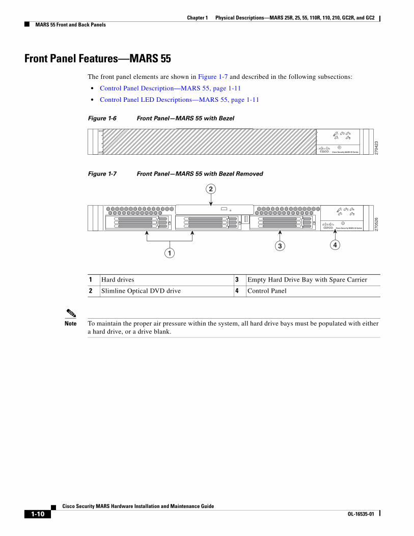
Front Panel Features—MARS 55The front panel elements are shown in Figure 1-7 and described in the following subsections:
• Control Panel Description—MARS 55, page 1-11
• Control Panel LED Descriptions—MARS 55, page 1-11
Figure 1-6 Front Panel—MARS 55 with Bezel
Figure 1-7 Front Panel—MARS 55 with Bezel Removed
Note To maintain the proper air pressure within the system, all hard drive bays must be populated with either a hard drive, or a drive blank.
27
04
23
!1
2
Cisco Security MARS 55 Series
1 Hard drives 3 Empty Hard Drive Bay with Spare Carrier
2 Slimline Optical DVD drive 4 Control Panel
27
05
26
!1
2
Cisco Security MARS 55 Series
2
3 4
1
1-10Cisco Security MARS Hardware Installation and Maintenance Guide
OL-16535-01

Chapter 1 Physical Descriptions—MARS 25R, 25, 55, 110R, 110, 210, GC2R, and GC2MARS 55 Front and Back Panels
Control Panel Description—MARS 55
The MARS 55 control panel has a power button and status LEDs. Figure 1-8 shows the layout and functions of the control panel.
Figure 1-8 Control Panel Elements—MARS 55
Control Panel LED Descriptions—MARS 55
Table 1-6 describes the function of control panel LEDs.
1 NIC 1 LED 4 Not used
2 NIC 2 LED 5 Hard Drive Activity LED
3 System Power LED 6 Power On/Off Button
27
05
28
!1
2
Cisco Security MARS 55 Series
31 4
6
2 5
Table 1-6 Control Panel LEDs—MARS 55
Figure 1-8 Reference Number
Control Panel LED State Description
1 NIC 1 LED Steady Green—NIC has link
Blinking Green—NIC Activity2 NIC 2 LED
3 Power On/Off LED Steady Green—Legacy power on
Blinking Green—Sleep state (not supported)
Off—Power is off.
4 Not used
5 Hard Drive LED Random blinking—indicates disk activity
Off—No disk activity
1-11Cisco Security MARS Hardware Installation and Maintenance Guide
OL-16535-01
Chapter 1 Physical Descriptions—MARS 25R, 25, 55, 110R, 110, 210, GC2R, and GC2MARS 110R, 110, 210, GC2R, and GC2 Front and Back Panels
Back Panel Features—MARS 55Figure 1-9 depicts the back panel of the MARS 55 appliance.
Figure 1-9 Back Panel—MARS 25R, 25, and 55
MARS 110R, 110, 210, GC2R, and GC2 Front and Back Panels This section consists of the following subsections:
• Front Panel Features—MARS 110R, 110, 210, GC2R, and GC2, page 1-12
• Back Panel Features—MARS 110R, 110, 210, GC2R, and GC2, page 1-17
Front Panel Features—MARS 110R, 110, 210, GC2R, and GC2The front panel elements are shown in Figure 1-10 and described in the following subsections:
• Control Panel Description—MARS 110R, 110, 210, GC2R, and GC2, page 1-13
• Control Panel LED Descriptions—MARS 110R, 110, 210, GC2R, and GC2, page 1-15
1 AC Power Connector 6 USB Ports 0 and 1 (not supported)
2 PS2 Mouse Port 7 NIC 2 or eth1(10/100/1000 Mps)
3 DB9 Serial Port 8 Diagnostic LEDs (4)1
1. Used by Technical Assistance Center for troubleshooting.
4 NIC 1 or eth0 (10/100/1000 Mps) 9 VGA Video Connector
5 Modem 10 PS2 Keyboard Port
27
04
22
1 2 3 4 5
79 810 6
1-12Cisco Security MARS Hardware Installation and Maintenance Guide
OL-16535-01
Chapter 1 Physical Descriptions—MARS 25R, 25, 55, 110R, 110, 210, GC2R, and GC2MARS 110R, 110, 210, GC2R, and GC2 Front and Back Panels
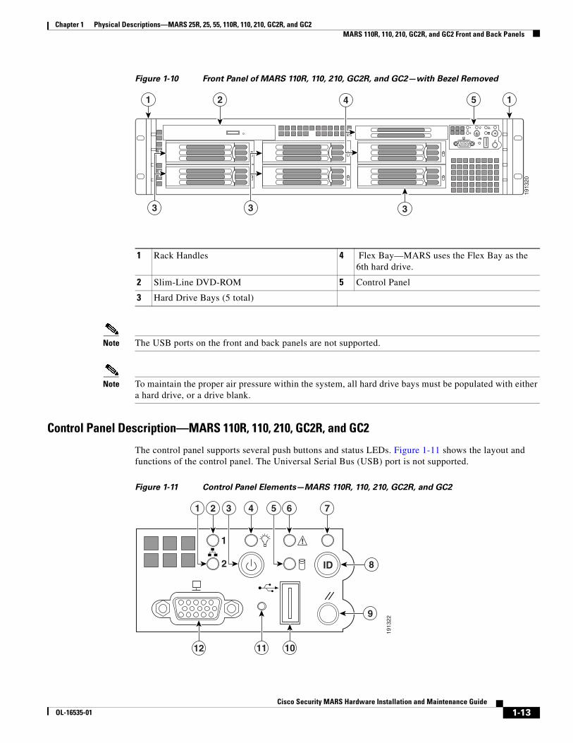
Figure 1-10 Front Panel of MARS 110R, 110, 210, GC2R, and GC2—with Bezel Removed
Note The USB ports on the front and back panels are not supported.
Note To maintain the proper air pressure within the system, all hard drive bays must be populated with either a hard drive, or a drive blank.
Control Panel Description—MARS 110R, 110, 210, GC2R, and GC2
The control panel supports several push buttons and status LEDs. Figure 1-11 shows the layout and functions of the control panel. The Universal Serial Bus (USB) port is not supported.
Figure 1-11 Control Panel Elements—MARS 110R, 110, 210, GC2R, and GC2
1 Rack Handles 4 Flex Bay—MARS uses the Flex Bay as the 6th hard drive.
2 Slim-Line DVD-ROM 5 Control Panel
3 Hard Drive Bays (5 total)
!1
2 ID
1913
20
2 4 5
33
1 1
3
1913
22
!1
2 ID 8
21 43 65 7
9
11 1012
1-13Cisco Security MARS Hardware Installation and Maintenance Guide
OL-16535-01

Chapter 1 Physical Descriptions—MARS 25R, 25, 55, 110R, 110, 210, GC2R, and GC2MARS 110R, 110, 210, GC2R, and GC2 Front and Back Panels
1 NIC 2 activity LED 7 System Identification LED—Toggles the front and rear panel System ID LEDs on/off enabling you to more easily locate the appliance from behind a rack.
2 NIC 1 activity LED 8 System identification button
3 Power on/off button—Toggles the system power on and off. Use for hard power-downs when a software shut down cannot be performed.
9 System Reset button—Reboots and initializes the system. Use for system restarts and initialization when a software reboot cannot be performed. Data in memory is lost, but RAID cache data is preserved.
4 Power LED 10 USB 2.0 Connector (Not supported)
5 Hard drive activity LED 11 Recessed Non-maskable Interrupt (NMI) Button (Tool Required)—Diagnostic function used by Cisco TAC
6 System status LED 12 VGA video-out connector—Standard VGA video-out connector. Attach an external monitor and a keyboard to the appliance to access the command line interface. It cannot be used at the same time as the back panel VGA connector.
1-14Cisco Security MARS Hardware Installation and Maintenance Guide
OL-16535-01

Chapter 1 Physical Descriptions—MARS 25R, 25, 55, 110R, 110, 210, GC2R, and GC2MARS 110R, 110, 210, GC2R, and GC2 Front and Back Panels
Control Panel LED Descriptions—MARS 110R, 110, 210, GC2R, and GC2
Table 1-7 describes the function of control panel LEDs.
Table 1-7 Control Panel LEDs—MARS 110R, 110, 210, GC2R, and GC2
Control Panel LED Figure 1-11 Reference Number
State Description
NIC 1 or NIC 2 LED 2, 1 Steady Green—NIC has link
Blinking Green—NIC Activity
Power On/Off LED 4 Steady Green—Legacy power on
Blinking Green—Sleep state (not supported)
Off—Power is off.
System Identification LED 7
Note This LED is also on the back panel
Solid Blue—Blue identification LEDs are on
Off—Blue identification LEDs are off
1-15Cisco Security MARS Hardware Installation and Maintenance Guide
OL-16535-01
Chapter 1 Physical Descriptions—MARS 25R, 25, 55, 110R, 110, 210, GC2R, and GC2MARS 110R, 110, 210, GC2R, and GC2 Front and Back Panels
System Status LED 6
Note This LED is also on the back panel
Alternating Green and Amber Blink—Pre-DC 5V standby power is on. There are 15–20 seconds of system initialization when AC is applied to the appliance. The control panel buttons are disabled until initialization is complete.
Solid Green—System booted and ready
Blinking Green—Degraded system, may be due to the following:
• Cannot use some of the installed memory
• Redundancy loss such as a power-supply or a fan
• CPU failed or disabled
• Fan alarm or fan failure. The number of operational fans should be more than the minimum number required to cool the system
• Non-critical threshold crossed such as temperature or voltage.
Solid Amber—Fatal alarm, the system has failed or shutdown possibly due to one of the following conditions:
• DIMM failure
• Run-time memory uncorrectable error in non-redundant mode
• IERR signal asserted
• Processor 1 missing
• Temperature threshold crossed
• Power fault
• Processor configuration error
Blinking Amber—Non-fatal alarm but system is likely to fail possibly due to one of the following conditions:
• Critical voltage threshold crossed
• Minimum number of fans to cool the system failed or not present
Off—POST is running or system is off
Table 1-7 Control Panel LEDs—MARS 110R, 110, 210, GC2R, and GC2
Control Panel LED Figure 1-11 Reference Number
State Description
1-16Cisco Security MARS Hardware Installation and Maintenance Guide
OL-16535-01

Chapter 1 Physical Descriptions—MARS 25R, 25, 55, 110R, 110, 210, GC2R, and GC2MARS 110R, 110, 210, GC2R, and GC2 Front and Back Panels
Back Panel Features—MARS 110R, 110, 210, GC2R, and GC2Figure 1-12 depicts the back panel of the MARS 110R, 110, 210, GC2R, and GC2 appliances.
Figure 1-12 Back Panel—MARS 110R, 110, 210, GC2R, and GC2
Hard Drive LED 5 Random blinking—indicates disk activity
Off—No disk activity
Table 1-7 Control Panel LEDs—MARS 110R, 110, 210, GC2R, and GC2
Control Panel LED Figure 1-11 Reference Number
State Description
1 (Not supported). Low Profile Add-in Slots for PCIe Cards
11 POST Progress LEDs (4)
2 (Not supported). Add-in 10/100/1000 Network Interface Card
12 (Not supported). USB port 5 and USB port 6
3 Fans—Upper Power Supply Module 13 VGA Video-out connector
4 LED and power receptacle for the upper power supply module
14 DB-9 Serial A connector
5 Power supply locking levers 15 Blue System Identification LED
6 LED and power receptacle for the lower power supply module
16 System Status LED
7 Fans—Lower Power Supply Module 17 Integrated NIC 2 (eth1-10/100/1000 Mbps)
8 (Not supported). Intel® I/O Expansion Module bay
18 Integrated NIC 1 (eth0-10/100/1000 Mbps)
9 (Not supported). Intel® Remote Management Module NIC bay
19 RJ45 Serial B connector
10 56K modem (Line In and Telephone connectors)
20 PS/2 keyboard and mouse connectors
1913
21
1
19
2 4 53
13 10 8 7 69121418 17 16
15
20 11
1-17Cisco Security MARS Hardware Installation and Maintenance Guide
OL-16535-01
Chapter 1 Physical Descriptions—MARS 25R, 25, 55, 110R, 110, 210, GC2R, and GC2Hard Drive Slot Number Maps
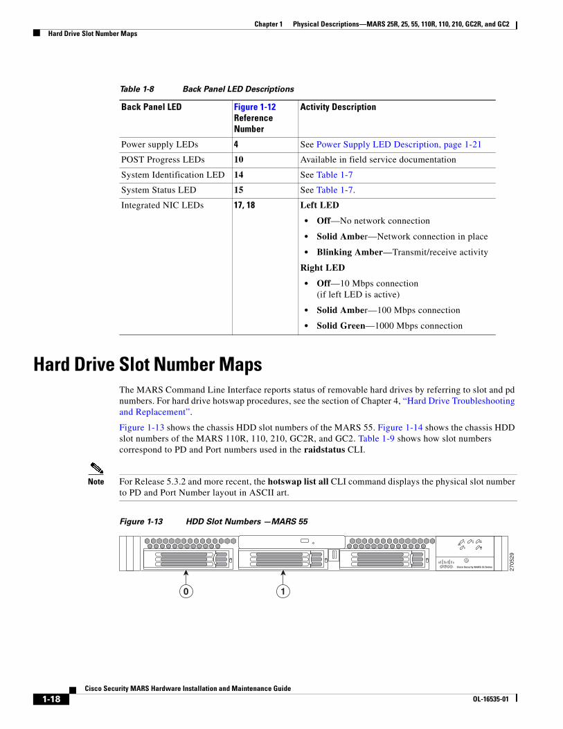
Hard Drive Slot Number MapsThe MARS Command Line Interface reports status of removable hard drives by referring to slot and pd numbers. For hard drive hotswap procedures, see the section of Chapter 4, “Hard Drive Troubleshooting and Replacement”.
Figure 1-13 shows the chassis HDD slot numbers of the MARS 55. Figure 1-14 shows the chassis HDD slot numbers of the MARS 110R, 110, 210, GC2R, and GC2. Table 1-9 shows how slot numbers correspond to PD and Port numbers used in the raidstatus CLI.
Note For Release 5.3.2 and more recent, the hotswap list all CLI command displays the physical slot number to PD and Port Number layout in ASCII art.
Figure 1-13 HDD Slot Numbers —MARS 55
Table 1-8 Back Panel LED Descriptions
Back Panel LED Figure 1-12 Reference Number
Activity Description
Power supply LEDs 4 See Power Supply LED Description, page 1-21
POST Progress LEDs 10 Available in field service documentation
System Identification LED 14 See Table 1-7
System Status LED 15 See Table 1-7.
Integrated NIC LEDs 17, 18 Left LED
• Off—No network connection
• Solid Amber—Network connection in place
• Blinking Amber—Transmit/receive activity
Right LED
• Off—10 Mbps connection (if left LED is active)
• Solid Amber—100 Mbps connection
• Solid Green—1000 Mbps connection
27
05
29
!1
2
Cisco Security MARS 55 Series
10
1-18Cisco Security MARS Hardware Installation and Maintenance Guide
OL-16535-01

Chapter 1 Physical Descriptions—MARS 25R, 25, 55, 110R, 110, 210, GC2R, and GC2Power Supplies
Figure 1-14 HDD Slot Numbers—MARS 110R, 110, 210, GC2R, and GC2
Power SuppliesThis section consists of the following subsections:
MARS 110R, 110, 210, GC2R, and GC2 Power Supply, page 1-20
MARS 25R, 25, and 55 Power Supply, page 1-22
For procedures on hotswapping a power supply, see Chapter 5, “Hot-swapping a Power Supply Unit”
!1
2 ID
19
16
50
0
1
2
3
4
5
Table 1-9 Mapping HDD Slot Number to raidstatus CLI Command PD number— MARS 55, 110R, 110, 210, GC2R, and GC2
MARS Appliance Storage Capacity1
Chassis HDD Slot to Port or PD Numbers2 RAID 1 Pairs
MARS 55 500GB RAID 1
2 X 500GB SATA-IO 3.0 Gbps HDD 7200 RPM, 16MB Buffer
Hot-Swappable Front Accessible
Slot 0 is Port 0 Slot 1 is Port 1
Slot 0 and Slot 1
MARS 110R, 110 1.5TB RAID 10 6 X 500GB SATA-IO 3.0 Gbps HDD 7200 RPM, 16MB Buffer
Hot-swappable Front accessible
Slot 0 is p0 Slot 1 is p1 Slot 2 is p2 Slot 3 is p3 Slot 4 is p4 Slot 5 is p5
Slot 0 and Slot 1
Slot 2 and Slot 3
Slot 4 and Slot 5
MARS 210, GC2R, GC2 2.0TB3 RAID 10 6 X 750GB SATA-IO 3.0 Gbps HDD 7200 RPM, 16MB Buffer
Hot-swappable Front accessible
1. The stated storage capacity is the sum of the rated capacity of all the hard drives and does reflect bytes reserved for the RAID overhead on each drive.
2. As of Release 5.3.2, the hotswap list all command displays a map of physical slot locations with their Port and PD Numbers
3. Although there is a total of 4.5 TB storage, RAID 10 has a maximum size configuration of 2 TB Redundant, or 4 TB
1-19Cisco Security MARS Hardware Installation and Maintenance Guide
OL-16535-01

Chapter 1 Physical Descriptions—MARS 25R, 25, 55, 110R, 110, 210, GC2R, and GC2Power Supplies
MARS 110R, 110, 210, GC2R, and GC2 Power SupplyThe MARS 110R, 110, 210, GC2R, and GC2 ship with two hot-swappable 750 watt redundant (1 + 1) ATX power supplies (PS) which have the following integrated management features:
• Status LED on each power module
• Over-temperature protection (OTP)
• Over-voltage protection (OVP)
Caution On a 20 amperes AC outlet, no more than a total of four (4) systems should be connected to a single outlet at any time.
Figure 1-15 Power Supply Module—MARS 110R, 110, 210, GC2R, and GC2
Over-Temperature Protection (OTP)
The power supply is protected against over-temperature conditions caused by loss of fan cooling or excessive ambient temperature. In an OTP condition the power supply will shutdown. When the power supply temperature drops to the rated safety limit, the power supply restores power automatically, while the 5 V standby remains constantly on. The power supply alerts the system of the OTP condition with the power supply FAIL signal and the Power LED on the control panel.
Over-Current Protection (OCP)
The power supply and power distribution board shutdown and latch off after an over-current condition occurs. This latch is cleared by an AC power interruption.
Over-Voltage Protection (OVP)
The power supply and power distribution board shutdown and latch off after an over-voltage condition occurs. This latch is cleared by an AC power interruption.
1 Integrated fan 2 Status LED
3 Retaining clip 4 AC power socket
5 Pull handle
3
1
4
2
15
1917
26
1-20Cisco Security MARS Hardware Installation and Maintenance Guide
OL-16535-01
Chapter 1 Physical Descriptions—MARS 25R, 25, 55, 110R, 110, 210, GC2R, and GC2Power Supplies
AC Power Source Requirements
Each power supply has a socket to accommodate an AC power cord. Each power supply operates within the parameters listed in Table 1-10.
Power Supply LED Description
Each power supply module has a two-color Amber/Green LED to indicate power supply status.
• Solid amber—Indicates no AC power for this power supply unit only, or there is a power supply critical event causing a shutdown. For instance, a general failure, a blown fuse, an over-current protection event, an over-voltage protection event, or a fan failure.
• 1Hz blinking amber— Power supply warning event is occurring and the power supply is operating. Warning events are high temperature, high power, high current, or slow fan.
• Solid green—Power supplies are operating normally
• 1Hz blinking green—AC power is present but only 5V standby is on (Power Button is off)
Table 1-10 Power Supply Maximums and Minimums—MARS 110R, 110, 210, GC2R, and GC2
Parameter 110 Line Voltage 220 Line Voltage
Minimum 90 Vrms 180 Vrms
Rated 100–127 Vrms 200–240 Vrms
Maximum 140 Vrms 264 Vrms
Start-up VAC 85 VAC +/– 4 VAC
Power Off VAC 75 VAC
Maximum Input AC Current1
1. Maximum input current at low input voltage range is measured at maximum load—minimums are 90VAC for a 110 Line, and 180VAC for a 220 Line.
12.0 Arms 6.0 Arms
Maximum Rated Input AC Current2
2. Maximum rated input current is measured at 100VAC and 200VAC.
11.0 Arms 5.5 Arms
Frequency Minimum: 47 Hz; Rated: 50/60 Hz; Maximum: 63 Hz
1-21Cisco Security MARS Hardware Installation and Maintenance Guide
OL-16535-01

Chapter 1 Physical Descriptions—MARS 25R, 25, 55, 110R, 110, 210, GC2R, and GC2Power Supplies
Checking Power Supply Operational Status
Example 1-1 displays the power supply status information in an excerpt of a show healthinfo CLI command output. The power supply unit should evaluated for hotswapping if the status is down. An email alert is sent to the administrator when a power supply changes status from “ok.” PS1 is the lower power supply, PS2 is the upper power supply. In normal operation, PS1 supplies most of the power requirements, and PS2 is the redundant power supply.
Example 1-1 Power Supply Status in the show healthinfo CLI Command.
[pnadmin]$ show healthinfo <SNIP>Power Supply Value Status----------------------------------------PS1 AC Current 2.36 Amps okPS2 AC Current 0.12 Amps okPS1 +12V Current 21 Amps okPS2 +12V Current 0 Amps okPS1 +12V Power 248 Watts okPS2 +12V Power 0 Watts okPS1 Status 0x01 okPS2 Status 0x09 ok
<SNIP>
MARS 25R, 25, and 55 Power SupplyThe MARS 25R, 25, and 55 have a single 350 watt ATX power supply (PS) with the following features:
• Over-temperature protection (OTP)
• Over-current protection (OCP)
• Over-voltage protection (OVP)
Over-Temperature Protection (OTP)
The power supply is protected against over-temperature conditions caused by loss of fan cooling or excessive ambient temperature. In an OTP condition the power supply will shutdown. When the power supply temperature drops to the rated safety limit, the power supply restores power automatically, while a 5 V standby remains constantly on. The power supply alerts the system of the OTP condition with the power supply FAIL signal and the Power LED on the control panel.
Over-Current Protection (OCP)
The power supply and power distribution board shutdown and latch off after an over-current condition occurs. This latch is cleared by an AC power interruption.
Over-Voltage Protection (OVP)
The power supply and power distribution board shutdown and latch off after an over-voltage condition occurs. This latch is cleared by an AC power interruption.
1-22Cisco Security MARS Hardware Installation and Maintenance Guide
OL-16535-01

Chapter 1 Physical Descriptions—MARS 25R, 25, 55, 110R, 110, 210, GC2R, and GC2Connector Descriptions
AC Power Source Requirements
The power supply operates within the parameters listed in Table 1-11.
Connector DescriptionsTable 1-12 describes the type and function of the back panel communication ports of the MARS 25R, 25, 55, 110R, 110, 210, GC2R, and GC2.
Table 1-11 MARS 25R, 25, and 55 Power Maximums and Minimums
Parameter 110 Line Voltage 220 Line Voltage
Minimum 90 Vrms 180 Vrms
Rated 100–127 Vrms 200–240 Vrms
Maximum 140 Vrms 264 Vrms
Start-up VAC 85 VAC +/– 4 VAC
Power Off VAC 75 VAC +/– 5 VAC
Maximum Input AC Current1
1. Maximum input current value is measured at maximum load and minimum voltage (90VAC for 110 line voltage, 180VAC for 220 line voltage.
6.0 Arms 3.0 Arms
Frequency Minimum: 47 Hz; Rated: 50/60 Hz; Maximum: 63 Hz
Table 1-12 Communication Port Descriptions—MARS 25R, 25, 55, 110R, 110, 210, GC2R, and GC2
Connector Description
DB-9 Serial Table 1-13 lists the pin number assignments for the 9-pin D-subminiature serial port connector.
RJ-45 Serial Table 1-14 lists the pin numbers assignments for the RJ-45 serial port connector.
Modem Line-in The MARS Appliance has a V.90 modem for sending SMS and pager alerts. Connect the line-in port to the wall jack using the provided standard telephone cable (RJ-11 connectors).
Modem External Telephone You can connect a POTS telephone to the telephone port with a standard telephone cable (RJ-11 connectors).
VGA Port Connect a monitor to this standard VGA port, and a keyboard to the keyboard port to view the console logs and to access the command line interface. It cannot be used at the same time as the Front Panel VGA connector.
Keyboard PS/2 keyboard connector. To access the console logs, or the command line interface connect a keyboard to the keyboard connector and a monitor to the VGA port.
1-23Cisco Security MARS Hardware Installation and Maintenance Guide
OL-16535-01

Chapter 1 Physical Descriptions—MARS 25R, 25, 55, 110R, 110, 210, GC2R, and GC2Connector Descriptions
Figure 1-16 Pin Numbers for the Serial Port Connector—MARS 110R, 110, 210, GC2R, and GC2
Mouse PS/2 mouse port. Not supported.
USB Ports (0 and 1) Not supported.
Ethernet Add-in NIC connectors Not supported.
Integrated Ethernet NIC connectors (eth0 and eth1)
10/100/1000–megabit-per-second (Mbps) autosensing Ethernet ports (autosensing detects line speed and duplex mode). MARS supports the operation of both Ethernet connectors. Table 1-7 lists LED descriptions. NIC 1 is eth0 and NIC 2 is eth1.
Each Ethernet connector provides all the functions of a network expansion card and supports the 10BASE-T, 100BASE-TX, and 1000BASE-TX Ethernet standards.
The MARS Appliance monitors network traffic destined to the IP address assigned to eth0. The eth0 connector is the port to which the gateway command applies. Therefore, eth0 must be attached to the network from which the reporting devices are accessible. The eth1 connector is typically used as an out-of-band management network, which provides faster graphical user interface (GUI) response to the administrator. To use eth1, you must define static routes to the destination networks for that interface.
Table 1-12 Communication Port Descriptions—MARS 25R, 25, 55, 110R, 110, 210, GC2R, and GC2
Connector Description
Table 1-13 DB-9 Serial Port Pin-outs—MARS 110R, 110, 210, GC2R, and GC2
Pin Signal Name Description
1 SPA_DCD DCD (Carrier Detect)
2 SPA_DSR DSR (Data Set Ready)
3 SPA_SIN_L RXD (Receive Data)
4 SPA_RTS RTS (Request to Send)
5 SPA_OUT_N TXD (Transmit Data)
6 SPA_CTS CTS (Clear to Send)
Serialport
15
69
7822
9
1-24Cisco Security MARS Hardware Installation and Maintenance Guide
OL-16535-01
Chapter 1 Physical Descriptions—MARS 25R, 25, 55, 110R, 110, 210, GC2R, and GC2Connector Descriptions
7 SPA_DTR DTR (Data Terminal Ready)
8 SPA_RI RI (Ring Indicate)
9 GND Ground
Table 1-14 RJ-45 Serial Port Pin-outs—MARS 110R, 110, 210, GC2R, and GC2
Pin Signal Name Description
1 SPB_RTS RTS (Request to Send)
2 SPB_DTR DTR (Data Terminal Ready)
3 SPB_OUT_N TXD (Transmit Data)
4 GND Ground
5 SPA_RI RI (Ring Indicate)
6 SPA_SIN_N RXD (Receive Data)
7 SPB_DSR DSR (Data Set Ready)
8 SPB_CTS CTS (Clear to Send)
Table 1-13 DB-9 Serial Port Pin-outs—MARS 110R, 110, 210, GC2R, and GC2
Pin Signal Name Description
1-25Cisco Security MARS Hardware Installation and Maintenance Guide
OL-16535-01

Chapter 1 Physical Descriptions—MARS 25R, 25, 55, 110R, 110, 210, GC2R, and GC2Connector Descriptions
1-26Cisco Security MARS Hardware Installation and Maintenance Guide
OL-16535-01
Cisco Security MOL-16535-01
C H A P T E R 2
Physical Descriptions—MARS 20R, 20, 50, 100E, 100, 200, GCm, and GCRevised: June 19 2008, OL-16535-01The Cisco Security MARS 20R, 20, 50, 100E, 100, 200, GCm, and GC appliances are built with the first generation of MARS hardware, and operate with only MARS software versions 4.x and 6.x.
This section consists of the following subsections:
• Part Numbers, License Key, Serial Numbers, and Warranty, page 2-1
• Technical Specifications, page 2-3
• MARS 20R and 20 Front and Back Panels, page 2-4
• MARS 50 Front and Back Panels, page 2-5
• MARS 100E and 100 Front and Back Panels, page 2-7
• MARS 200, GCm, and GC Front and Back Panels, page 2-8
• Connector Descriptions, page 2-10
• Hard Drive Layout—MARS 100E and 100, page 2-12
• Hard Drive Layout—MARS 200, GCm, and GC, page 2-13
Part Numbers, License Key, Serial Numbers, and WarrantyThis section contains the following subsections:
• Part Numbers, page 2-1
• Serial Numbers, page 2-2
• License Key, page 2-2
• Limited Warranty, page 2-3
Part NumbersThe part numbers of Cisco Security MARS Appliances and the Field Replaceable Units (FRUs) that operate with software releases 4.x and 6.x are as follows:
2-1ARS Hardware Installation and Maintenance Guide
Chapter 2 Physical Descriptions—MARS 20R, 20, 50, 100E, 100, 200, GCm, and GCPart Numbers, License Key, Serial Numbers, and Warranty
Local Controller Appliances
• CS-MARS-20R-K9
• CS-MARS-20-K9
• CS-MARS-50-K9
• CS-MARS-100E-K9
• CS-MARS-100-K9
• CS-MARS-200-K9
Global Controller Appliances
• CS-MARS-GCM-K9
• CS-MARS-GC-K9
Serial Numbers If you have difficulty identifying or physically locating the serial number sticker on your appliance chassis, use the Cisco Product Identification Tool at the following URL:
http://tools.cisco.com/Support/CPI/index.do
You must be registered with Cisco Systems Customer Connection Online to access this tool. If you are not registered, you can register at the following URL:
http://tools.cisco.com/RPF/register/register.do
The chassis, hard drive, and power supply serial numbers are also reported in the show inventory CLI command.
License Key The license key sticker is on the chassis, and on the Recovery DVD case shipped with your product. Figure 2-1 identifies the license key sticker location.
FRU Description FRU Part Number
Power Supply for Cisco Security MARS 100 and 100E
CS-MARS-100-PS=
Power Supply for Cisco Security MARS 200, GCM, and GC
CS-MARS-200-PS=
Replacement hard drive for Cisco Security MARS 100, 100E, 200, or GC
CS-MARS-X00-HD=
2-2Cisco Security MARS Hardware Installation and Maintenance Guide
OL-16535-01

Chapter 2 Physical Descriptions—MARS 20R, 20, 50, 100E, 100, 200, GCm, and GCTechnical Specifications
Figure 2-1 License Key Location
Limited WarrantyFor the warranty, disclaimer of warranty, and end user license agreement that applies to your product, refer to the version of the Cisco Security MARS Documentation Guide and Warranty that shipped with your product. You can view the latest versions of this document at:
http://www.cisco.com/en/US/products/ps6241/products_documentation_roadmaps_list.html
Technical SpecificationsTable 2-1 lists physical measurements and components of the Cisco Security MARS appliances. Table 2-2 describes the electrical characteristics and environmental operating parameters.
1434
21
1
Table 2-1 Chassis and Component Specifications
MARS 20, 20R MARS 50 MARS 100,100E MARS 200, GCM, GC
Weight 9.07 kg 20.0 lbs
12.7 kg 28.0 lbs
28.6 kg 63.0 lbs
43.1 kg 95.0 lbs
Rack Unit1
1. A rack unit (RU) is a standardized measure for the height of rack-mountable equipment. One RU is 44.45 mm (1.75 in) high, 482.6 mm (19 in.) wide.
1 RU x 16 in. (41 cm) 1 RU x 25.6 in. (65.0 cm)
3 RU x 25.6 in. (65.0 cm)
4 RU x 25.6 in. (65.0 cm)
Network Controller 2 X 10/100/1000 Integrated Ethernet
2 X 10/100/1000 Integrated Ethernet
2 X 10/100/1000 Integrated Ethernet
2 X 10/100/1000 Integrated Ethernet
Storage 120GB (non-RAID) 240GB RAID 0 750GB RAID 10 Hot-swappable
1 TB RAID 10 Hot-swappable
System battery Maxell or Varta CR2032 210mAh lithium 3V
Maxell or Varta CR2032 210mAh lithium 3V
Maxell or Varta CR2032 210mAh lithium 3V
Maxell or Varta CR2032 210mAh lithium 3V
DVD-ROM 24x SlimDVD-ROM 24x SlimDVD-ROM 24x SlimDVD-ROM 24x SlimDVD-ROM
2-3Cisco Security MARS Hardware Installation and Maintenance Guide
OL-16535-01
Chapter 2 Physical Descriptions—MARS 20R, 20, 50, 100E, 100, 200, GCm, and GCMARS 20R and 20 Front and Back Panels
MARS 20R and 20 Front and Back PanelsThis section consists of the following subsections:
• Front Panel Features—MARS 20R and 20, page 2-4
• Back Panel Features—MARS 20R and MARS 20, page 2-5
Front Panel Features—MARS 20R and 20 Figure 2-2 depicts the front panel of the MARS 20R and 20 appliances.
Table 2-2 Electrical and Environmental Specifications
MARS 20, 20R MARS 50 MARS 100,100E MARS 200, GCM, GC
Power Supply (Rated output, input voltage range, frequency range, minimum and maximum input current)
300W autoswitch 100-240 VAC, 50-60Hz 6A min. 10A max.
Same as MARS 20 500W dual-redundant 100-240 VAC, 50-60Hz 10A min. 10A max.
Same as MARS 100
Dissipated Heat — — 1, 000–1,700 BTU Same as MARS 100
Operating Temperatures and Humidity Range
5º C to 40ºC; 20% to 80% max. 27ºC wet bulb, noncondensing
Same as MARS 20 Same as MARS 20 Same as MARS 20
Non-operating Temperatures and Humidity Range
-20 to 60 ºC; 5% to 90% maximum 38 ºC wet bulb, noncondensing
Same as MARS 20 Same as MARS 20 Same as MARS 20
Vibration Operating: 0.2G, 5–500 Hz, swept sine
Nonoperating: 1.0 G, 5–500 Hz, swept sine
Same as MARS 20 Same as MARS 20 Same as MARS 20
Shock Operating: 3G peak, 11 ms half-sine
Nonoperating: 10G peak, 11 ms half-sine
Same as MARS 20 Same as MARS 20 Same as MARS 20
Altitude Operating: 3000 m (10,000 ft.)
Nonoperating: 12,000 m (40,000 ft.)
Same as MARS 20 Same as MARS 20 Same as MARS 20
Acoustic Noise Operating: 7.5 bel Same as MARS 20 Same as MARS 20 Same as MARS 20
2-4Cisco Security MARS Hardware Installation and Maintenance Guide
OL-16535-01

Chapter 2 Physical Descriptions—MARS 20R, 20, 50, 100E, 100, 200, GCm, and GCMARS 50 Front and Back Panels
Figure 2-2 Front Panel—MARS 20R and 20 l
Back Panel Features—MARS 20R and MARS 20 Figure 2-3 depicts the back panel of the MARS 20R and 20 appliances.
Figure 2-3 Back Panel—MARS 20R and 20
MARS 50 Front and Back PanelsThis section consists of the following subsections:
• Front Panel Features—MARS 50, page 2-6
• Back Panel Features—MARS 50, page 2-6
1 DVD drive 4 Power indicator light
2 DVD eject button 5 Face plate release screws
3 Power switch 6 Restart button
1322
29
RST
PWR
HDD
LAN
+
1 2 3
55 6
4
1 PS/2 Keyboard port 8 Power socket
2 PS/2 Mouse Port 9 Power switch
3 Parallel port (not supported) 10 VGA Port
4 eth1, Ethernet 1 port 11 Serial port
5 eth0, Ethernet 0 port 12 USB 0 port (not supported)
6 RJ-11 Line-in port 13 USB 1 port (not supported)
7 Telephone port (line out) 14 Serial number (begins with SN:)
1322
30
8 94 5 6 732
1
10111214 13
SN
2-5Cisco Security MARS Hardware Installation and Maintenance Guide
OL-16535-01
Chapter 2 Physical Descriptions—MARS 20R, 20, 50, 100E, 100, 200, GCm, and GCMARS 50 Front and Back Panels
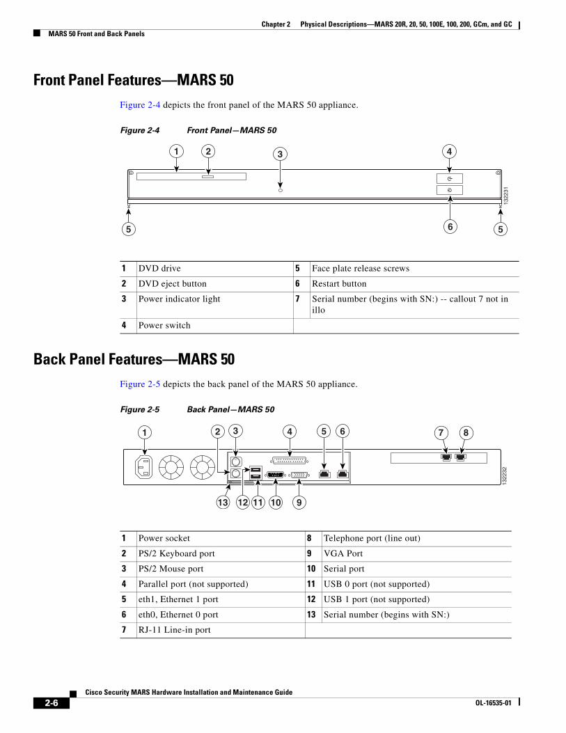
Front Panel Features—MARS 50Figure 2-4 depicts the front panel of the MARS 50 appliance.
Figure 2-4 Front Panel—MARS 50
Back Panel Features—MARS 50Figure 2-5 depicts the back panel of the MARS 50 appliance.
Figure 2-5 Back Panel—MARS 50
1 DVD drive 5 Face plate release screws
2 DVD eject button 6 Restart button
3 Power indicator light 7 Serial number (begins with SN:) -- callout 7 not in illo
4 Power switch
1322
31
1 2 4
55 6
3
1 Power socket 8 Telephone port (line out)
2 PS/2 Keyboard port 9 VGA Port
3 PS/2 Mouse port 10 Serial port
4 Parallel port (not supported) 11 USB 0 port (not supported)
5 eth1, Ethernet 1 port 12 USB 1 port (not supported)
6 eth0, Ethernet 0 port 13 Serial number (begins with SN:)
7 RJ-11 Line-in port
1322
32
1 7 8
SN
13 9101112
5 632 4
2-6Cisco Security MARS Hardware Installation and Maintenance Guide
OL-16535-01
Chapter 2 Physical Descriptions—MARS 20R, 20, 50, 100E, 100, 200, GCm, and GCMARS 100E and 100 Front and Back Panels
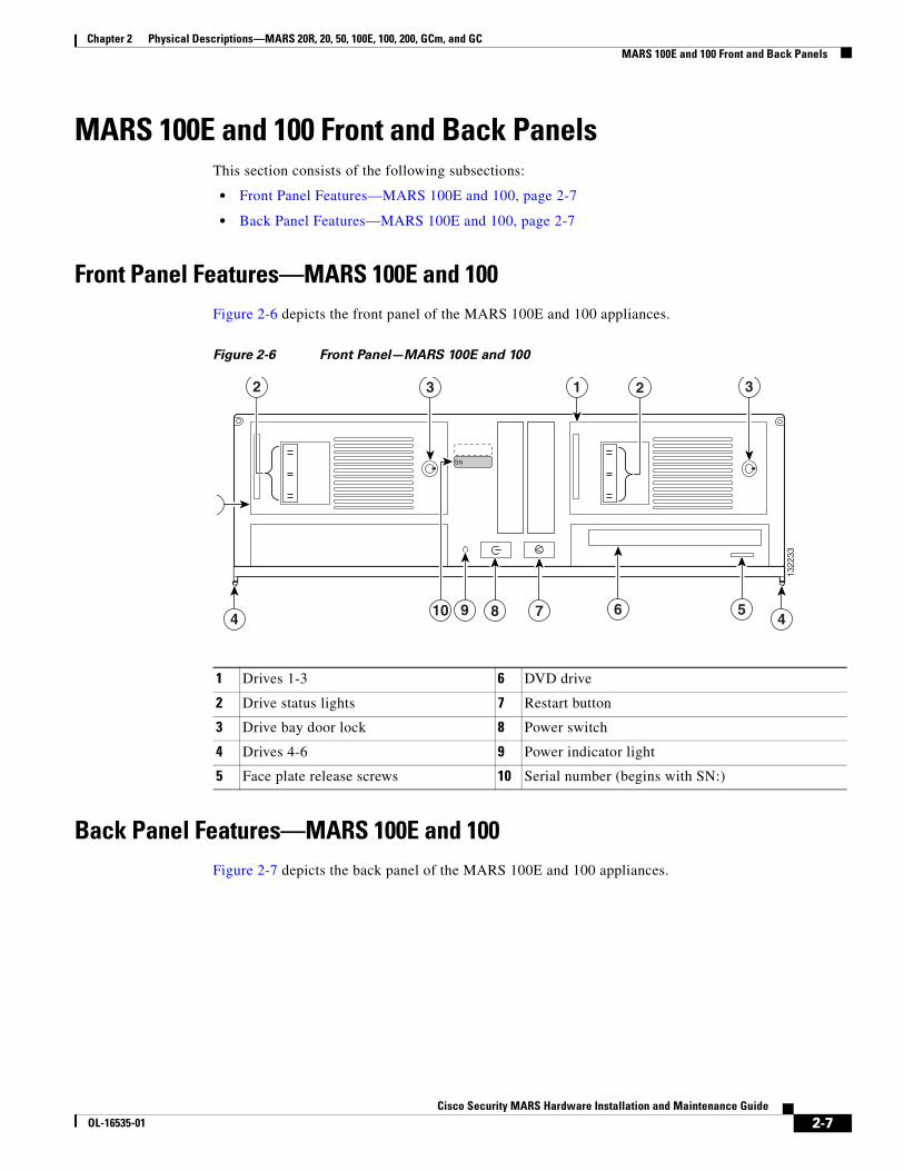
MARS 100E and 100 Front and Back PanelsThis section consists of the following subsections:
• Front Panel Features—MARS 100E and 100, page 2-7
• Back Panel Features—MARS 100E and 100, page 2-7
Front Panel Features—MARS 100E and 100Figure 2-6 depicts the front panel of the MARS 100E and 100 appliances.
Figure 2-6 Front Panel—MARS 100E and 100
Back Panel Features—MARS 100E and 100Figure 2-7 depicts the back panel of the MARS 100E and 100 appliances.
1 Drives 1-3 6 DVD drive
2 Drive status lights 7 Restart button
3 Drive bay door lock 8 Power switch
4 Drives 4-6 9 Power indicator light
5 Face plate release screws 10 Serial number (begins with SN:)13
2233
3 1
6 5789
2 2 3
4 4
SN
10
2-7Cisco Security MARS Hardware Installation and Maintenance Guide
OL-16535-01
Chapter 2 Physical Descriptions—MARS 20R, 20, 50, 100E, 100, 200, GCm, and GCMARS 200, GCm, and GC Front and Back Panels
Figure 2-7 Back Panel—MARS 100E and 100
MARS 200, GCm, and GC Front and Back PanelsThis section consists of the following subsections:
• Front Panel Features—MARS 200, GCm, and GC, page 2-8
• Back Panel Features—MARS 200, GCm, and GC, page 2-9
Front Panel Features—MARS 200, GCm, and GCFigure 2-8 depicts the front panel of the MARS 200, GCm, and GC appliances.
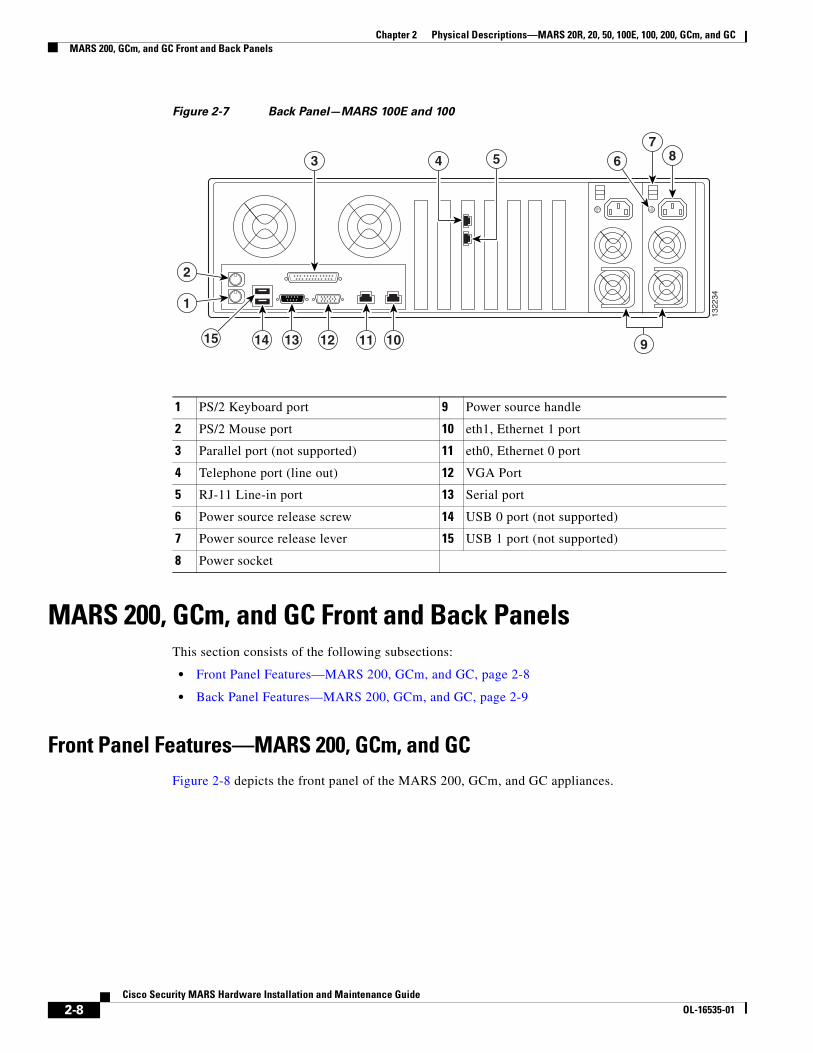
1 PS/2 Keyboard port 9 Power source handle
2 PS/2 Mouse port 10 eth1, Ethernet 1 port
3 Parallel port (not supported) 11 eth0, Ethernet 0 port
4 Telephone port (line out) 12 VGA Port
5 RJ-11 Line-in port 13 Serial port
6 Power source release screw 14 USB 0 port (not supported)
7 Power source release lever 15 USB 1 port (not supported)
8 Power socket
1322
34
101112
4 5 67
83
1
2
131415 9
2-8Cisco Security MARS Hardware Installation and Maintenance Guide
OL-16535-01
Chapter 2 Physical Descriptions—MARS 20R, 20, 50, 100E, 100, 200, GCm, and GCMARS 200, GCm, and GC Front and Back Panels
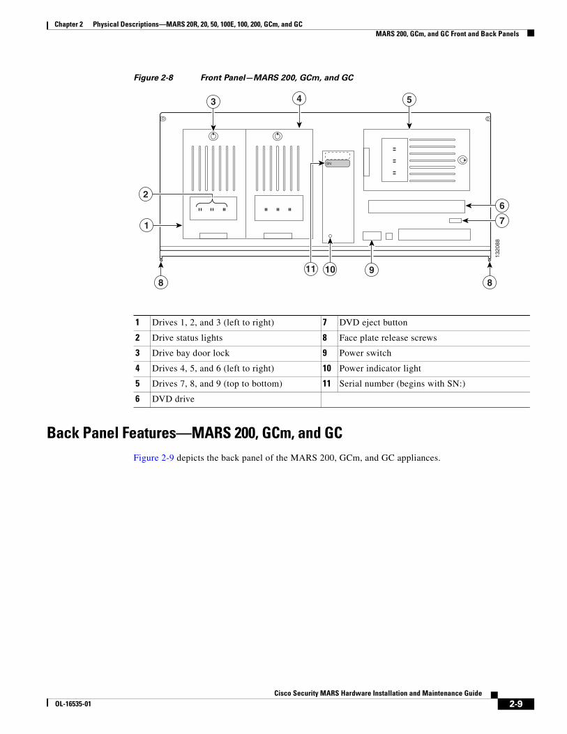
Figure 2-8 Front Panel—MARS 200, GCm, and GC
Back Panel Features—MARS 200, GCm, and GCFigure 2-9 depicts the back panel of the MARS 200, GCm, and GC appliances.
1 Drives 1, 2, and 3 (left to right) 7 DVD eject button
2 Drive status lights 8 Face plate release screws
3 Drive bay door lock 9 Power switch
4 Drives 4, 5, and 6 (left to right) 10 Power indicator light
5 Drives 7, 8, and 9 (top to bottom) 11 Serial number (begins with SN:)
6 DVD drive
1320
88
3 5
1
6
7
910
4
2
8 8
SN
11
2-9Cisco Security MARS Hardware Installation and Maintenance Guide
OL-16535-01
Chapter 2 Physical Descriptions—MARS 20R, 20, 50, 100E, 100, 200, GCm, and GCConnector Descriptions
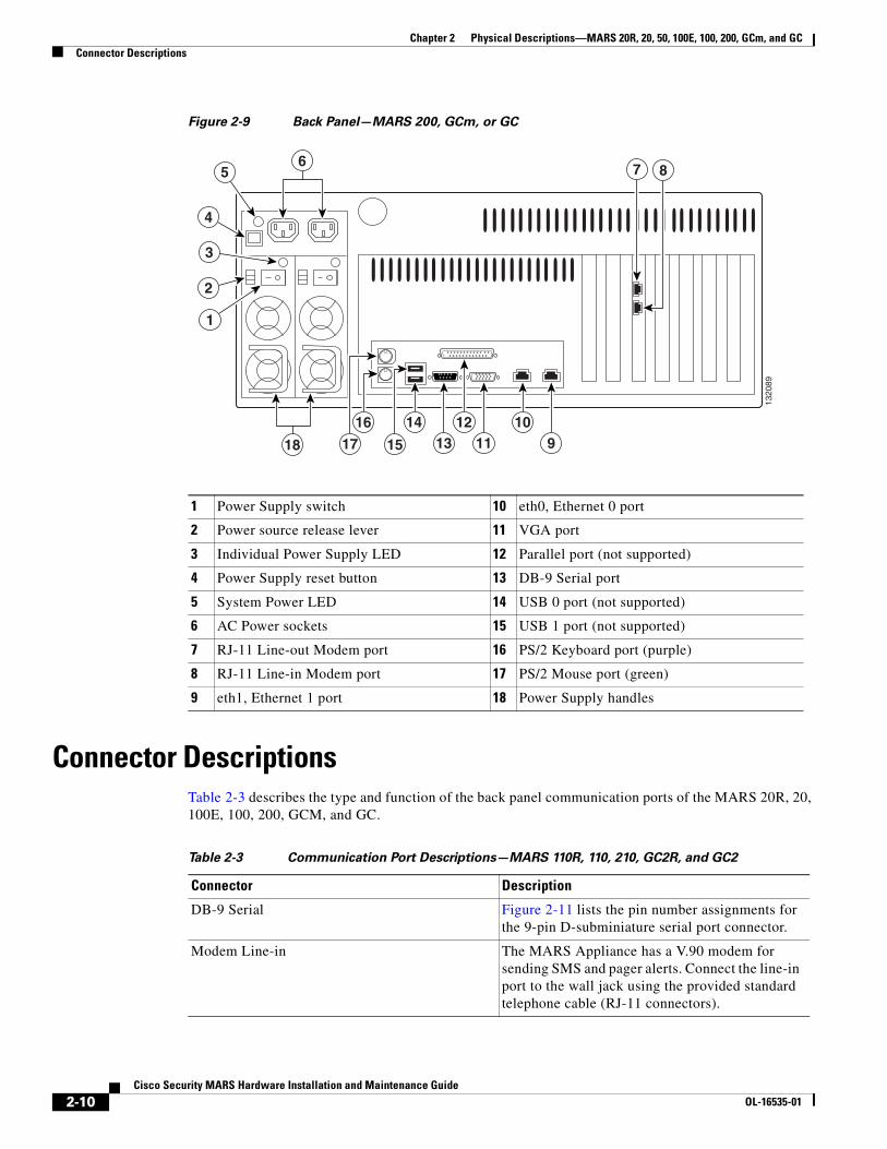
Figure 2-9 Back Panel—MARS 200, GCm, or GC
Connector DescriptionsTable 2-3 describes the type and function of the back panel communication ports of the MARS 20R, 20, 100E, 100, 200, GCM, and GC.
1 Power Supply switch 10 eth0, Ethernet 0 port
2 Power source release lever 11 VGA port
3 Individual Power Supply LED 12 Parallel port (not supported)
4 Power Supply reset button 13 DB-9 Serial port
5 System Power LED 14 USB 0 port (not supported)
6 AC Power sockets 15 USB 1 port (not supported)
7 RJ-11 Line-out Modem port 16 PS/2 Keyboard port (purple)
8 RJ-11 Line-in Modem port 17 PS/2 Mouse port (green)
9 eth1, Ethernet 1 port 18 Power Supply handles
1320
89
2
3
1
4
56
8
910
18 1112
1317
16
15
14
7
Table 2-3 Communication Port Descriptions—MARS 110R, 110, 210, GC2R, and GC2
Connector Description
DB-9 Serial Figure 2-11 lists the pin number assignments for the 9-pin D-subminiature serial port connector.
Modem Line-in The MARS Appliance has a V.90 modem for sending SMS and pager alerts. Connect the line-in port to the wall jack using the provided standard telephone cable (RJ-11 connectors).
2-10Cisco Security MARS Hardware Installation and Maintenance Guide
OL-16535-01

Chapter 2 Physical Descriptions—MARS 20R, 20, 50, 100E, 100, 200, GCm, and GCConnector Descriptions
DB-9 Serial PortThe integrated serial port on the back panel of the appliance uses a 9-pin D-subminiature connector.
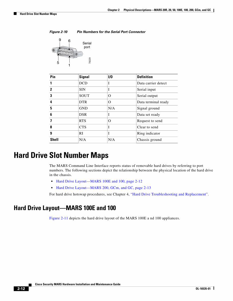
If you reconfigure your hardware, you may need information regarding the pin number and signal for the serial port connector. Figure 2-10 illustrates the pin numbers for the serial port connector and defines the pin assignments and interface signals for the serial port connector. (Pin numbering proceeds bottom to top and right to left, as illustrated.)
Modem Line-out You can connect a POTS telephone to the telephone port with a standard telephone cable (RJ-11 connectors).
VGA Port Connect a monitor to this standard VGA port, and a keyboard to the keyboard port to view the console logs and to access the command line interface.
Keyboard PS/2 keyboard connector. To access the console logs, or the command line interface connect a keyboard to the keyboard connector and a monitor to the VGA port.
Centronics Parallel Port Not supported
PS/2 Mouse port Not supported
USB Ports (0 and 1) Not supported
Integrated Ethernet NIC connectors (eth0 and eth1)
10/100/1000–megabit-per-second (Mbps) autosensing Ethernet ports (autosensing detects line speed and duplex mode). MARS supports the operation of both Ethernet connectors.
Each Ethernet connector provides all the functions of a network expansion card and supports the 10BASE-T, 100BASE-TX, and 1000BASE-TX Ethernet standards.
The MARS Appliance monitors network traffic destined to the IP address assigned to eth0. The eth0 connector is the port to which the gateway command applies. Therefore, eth0 must be attached to the network from which the reporting devices are accessible. The eth1 connector is typically used as an out-of-band management network, which provides faster graphical user interface (GUI) response to the administrator. To use eth1, you must define static routes to the destination networks for that interface.
Table 2-3 Communication Port Descriptions—MARS 110R, 110, 210, GC2R, and GC2
Connector Description
2-11Cisco Security MARS Hardware Installation and Maintenance Guide
OL-16535-01
Chapter 2 Physical Descriptions—MARS 20R, 20, 50, 100E, 100, 200, GCm, and GCHard Drive Slot Number Maps
Figure 2-10 Pin Numbers for the Serial Port Connector
Hard Drive Slot Number MapsThe MARS Command Line Interface reports status of removable hard drives by referring to port numbers. The following sections depict the relationship between the physical location of the hard drive in the chassis.
• Hard Drive Layout—MARS 100E and 100, page 2-12
• Hard Drive Layout—MARS 200, GCm, and GC, page 2-13
For hard drive hotswap procedures, see Chapter 4, “Hard Drive Troubleshooting and Replacement”.
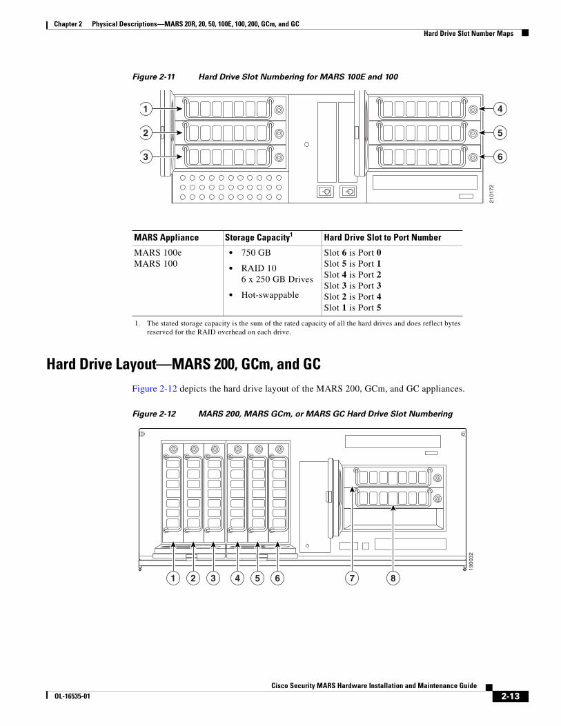
Hard Drive Layout—MARS 100E and 100 Figure 2-11 depicts the hard drive layout of the MARS 100E a nd 100 appliances.
Pin Signal I/O Definition
1 DCD I Data carrier detect
2 SIN I Serial input
3 SOUT O Serial output
4 DTR O Data terminal ready
5 GND N/A Signal ground
6 DSR I Data set ready
7 RTS O Request to send
8 CTS I Clear to send
9 RI I Ring indicator
Shell N/A N/A Chassis ground
Serialport
15
69
7822
9
2-12Cisco Security MARS Hardware Installation and Maintenance Guide
OL-16535-01
Chapter 2 Physical Descriptions—MARS 20R, 20, 50, 100E, 100, 200, GCm, and GCHard Drive Slot Number Maps
Figure 2-11 Hard Drive Slot Numbering for MARS 100E and 100
Hard Drive Layout—MARS 200, GCm, and GCFigure 2-12 depicts the hard drive layout of the MARS 200, GCm, and GC appliances.
Figure 2-12 MARS 200, MARS GCm, or MARS GC Hard Drive Slot Numbering
MARS Appliance Storage Capacity1
1. The stated storage capacity is the sum of the rated capacity of all the hard drives and does reflect bytes reserved for the RAID overhead on each drive.
Hard Drive Slot to Port Number
MARS 100e MARS 100
• 750 GB
• RAID 10 6 x 250 GB Drives
• Hot-swappable
Slot 6 is Port 0 Slot 5 is Port 1 Slot 4 is Port 2 Slot 3 is Port 3 Slot 2 is Port 4 Slot 1 is Port 5
2101
72
1
2
3
4
5
6
1900
32
871 2 3 4 5 6
2-13Cisco Security MARS Hardware Installation and Maintenance Guide
OL-16535-01

Chapter 2 Physical Descriptions—MARS 20R, 20, 50, 100E, 100, 200, GCm, and GCHard Drive Slot Number Maps
MARS Appliance Storage Capacity1
1. The stated storage capacity is the sum of the rated capacity of all the hard drives and does reflect bytes reserved for the RAID overhead on each drive.
Hard Drive Slot to Port Number
MARS 200, GC, GCM • 1 TB
• RAID 10 8 x 250 GB Drives
• Hot-swappable
Slot 8 is Port 0 Slot 7 is Port 1 Slot 6 is Port 2 Slot 5 is Port 3 Slot 4 is Port 4 Slot 3 is Port 5 Slot 2 is Port 6 Slot 1 is Port 7
2-14Cisco Security MARS Hardware Installation and Maintenance Guide
OL-16535-01
Cisco Security MOL-16535-01
C H A P T E R 3
Preparing for InstallationRevised: November 18, 2008, OL-16535-01
Note At the time of Cisco Security MARS Release 6.0.1, the Cisco Security MARS Appliances 20R, 20, 50, 100E, 100, 200, GCM, and GC were no longer orderable, but the hardware installation information is retained in this manual for your reference.
This chapter describes safety instructions and site requirements for installing the MARS Appliance and guides you through installation preparation. It contains the following sections:
• Safety, page 3-1
• Preparing Your Site for Installation, page 3-5
• Precautions for Rack-Mounting, page 3-8
• Precautions for Products with Modems, Telecommunications, or Local Area Network Options, page 3-9
• Required Tools and Equipment, page 3-9
• Packaging Contents Checklist, page 3-9
SafetyThis section provides safety information for installing this product.
Warnings and CautionsRead the installation instructions in this document before you connect the system to its power source. Failure to read and follow these guidelines could lead to an unsuccessful installation and possibly damage the system and components.
You should observe the following safety guidelines when working with any equipment that connects to electrical power or telephone wiring. They can help you avoid injuring yourself or damaging the MARS Appliance.
3-1ARS Hardware Installation and Maintenance Guide
Chapter 3 Preparing for InstallationSafety
Note The English warnings in this document are followed by a statement number. To see the translations of a warning into other languages, look up the statement number in one of the following documents:
• Regulatory Compliance and Safety Information for the Cisco Security MARS Appliances 20R, 20, 50, 100E, 100, 200, GCM, and GC
• Regulatory Compliance and Safety Information for the Cisco Security MARS Appliances, 25R, 25, 55, 110R, 110, 210, GC2R, and GC2
The following warnings and cautions are provided to help you prevent injury to yourself or damage to the devices:
Warning Before working on a system that has an On/Off switch, turn OFF the power and unplug the power cord. Statement 1
Warning Before working on a chassis or working near power supplies, unplug the power cord on AC units; disconnect the power at the circuit breaker on DC units. Statement 12
Warning This unit is intended for installation in restricted access areas. A restricted access area is where access can only be gained by service personnel through the use of a special tool, lock and key, or other means of security, and is controlled by the authority responsible for the location. Statement 37
Warning This unit might have more than one power cord. To reduce the risk of electrical shock, disconnect all power supply cords before servicing the unit. Statement 106
Warning The safety cover is an integral part of the product. Do not operate the unit without the safety cover installed. Operating the unit without the cover in place will invalidate the safety approvals and pose a risk of fire and electrical hazards. Statement 117
Warning Do not work on the system or connect or disconnect cables during periods of lightning activity. Statement 1001.
Warning Read the installation instructions before you connect the system to its power source. Statement 1004
Warning To prevent bodily injury when mounting or servicing this unit in a rack, you must take special precautions to ensure that the system remains stable. The following guidelines are provided to ensure your safety: Statement 1006
3-2Cisco Security MARS Hardware Installation and Maintenance Guide
OL-16535-01
Chapter 3 Preparing for InstallationSafety
Warning There is the danger of explosion if the battery is replaced incorrectly. Replace the battery only with the same or equivalent type recommended by the manufacturer. Dispose of used batteries according to the manufacturer’s instructions. Statement 1015
Warning This equipment must be grounded. Never defeat the ground conductor or operate the equipment in the absence of a suitably installed ground conductor. Contact the appropriate electrical inspection authority or an electrician if you are uncertain that suitable grounding is available. Statement 1024
Warning Blank faceplates and cover panels serve three important functions: they prevent exposure to hazardous voltages and currents inside the chassis; they contain electromagnetic interference (EMI) that might disrupt other equipment; and they direct the flow of cooling air through the chassis. Do not operate the system unless all cards, faceplates, front covers, and rear covers are in place. Statement 1029
Warning Ultimate disposal of this product should be handled according to all national laws and regulations. Statement 1040
Warning Before opening the chassis, disconnect the telephone-network cables to avoid contact with telephone-network voltages. Statement 1041
Warning This product requires short-circuit (overcurrent) protection, to be provided as part of the building installation. Install only in accordance with national and local wiring regulations. Statement 1045
Warning IMPORTANT SAFETY INSTRUCTIONS This warning symbol means danger. You are in a situation that could cause bodily injury. Before you work on any equipment, be aware of the hazards involved with electrical circuitry and be familiar with standard practices for preventing accidents. Use the statement number provided at the end of each warning to locate its translation in the translated safety warnings that accompanied this device. Statement 1071 SAVE THESE INSTRUCTIONS
General PrecautionsObserve the following general precautions when using and working with your system:
• Keep your system components away from radiators and heat sources, and do not block cooling vents.
3-3Cisco Security MARS Hardware Installation and Maintenance Guide
OL-16535-01

Chapter 3 Preparing for InstallationSafety
• Do not spill food or liquids on your system components, and never operate the product in a wet environment. If the computer gets wet, see the appropriate chapter in your troubleshooting guide or contact the Cisco Technical Assistance Center. For instructions on contacting the Technical Assistance Center, see Obtaining Documentation, Obtaining Support, and Security Guidelines, page xiv, in the Preface.
• Do not push any objects into the openings of your system components. Doing so can cause fire or electric shock by shorting out interior components.
• Position system cables and power cables carefully; route system cables and the power cable and plug so that they cannot be stepped on or tripped over. Be sure that nothing rests on your system components’ cables or power cable.
• Do not modify power cables or plugs. Consult a licensed electrician or your power company for site modifications. Always follow your local/national wiring rules.
• To avoid possible damage to the system board, wait 5 seconds after turning off the system before removing a component from the system board or disconnecting a peripheral device from the computer.
Maintaining Safety with ElectricityFollow these guidelines when working on equipment powered by electricity:
• If any of the following conditions occur contact the Cisco Technical Assistance Center:
– The power cable or plug is damaged.
– An object has fallen into the product.
– The product has been exposed to water.
– The product has been dropped or damaged.
– The product does not operate correctly when you follow the operating instructions.
• Use the correct external power source. Operate the product only from the type of power source indicated on the electrical ratings label. If you are not sure of the type of power source required, consult the Cisco Technical Assistance Center or a local power company.
• Use only approved power cable(s). You have been provided with a power cable for your MARS Appliance that is intended for your system (approved for use in your country, based on the shipping location). Should you have to purchase a power cable, ensure that it is rated for the product and for the voltage and current marked on the product’s electrical ratings label. The voltage and current rating of the cable should be greater than the ratings marked on the product.
• To help prevent electric shock, plug the MARS Appliance, components, and peripheral power cables into properly grounded electrical outlets. These cables are equipped with three-prong plugs to help ensure proper grounding. Do not use adapter plugs or remove the grounding prong from a cable.
• Observe power strip ratings. Make sure that the total ampere rating of all products plugged into the power strip does not exceed 80% of the rating.
• To help protect your system and components from sudden, transient increases and decreases in electrical power, Cisco recommends the use an uninterruptable power supply (UPS) for your MARS Appliances.
• Do not modify power cables or plugs. Consult a licensed electrician or your power company for site modifications. Always follow your local and national wiring rules.
3-4Cisco Security MARS Hardware Installation and Maintenance Guide
OL-16535-01
Chapter 3 Preparing for InstallationPreparing Your Site for Installation
Protecting Against Electrostatic DischargeStatic electricity can harm delicate components inside your computer. To prevent static damage, discharge static electricity from your body before you touch any of your computer’s electronic components, such as the microprocessor. You can do so by touching an unpainted metal surface on the computer chassis.
As you continue to work inside the computer, periodically touch an unpainted metal surface to remove any static charge your body may have accumulated.
You can also take the following steps to prevent damage from electrostatic discharge (ESD):
• When unpacking a static-sensitive component from its shipping carton, do not remove the component from the antistatic packing material until you are ready to install the component in your computer. Just before unwrapping the antistatic packaging, be sure to discharge static electricity from your body.
• When transporting a sensitive component, first place it in an antistatic container or packaging.
• Handle all sensitive components in a static-safe area. If possible, use antistatic floor pads and workbench pads.
Preventing EMIWhen you run wires for any significant distance in an electromagnetic field, electromagnetic interference (EMI) can occur between the field and the signals on the wires.
Note Bad plant wiring can result in radio frequency interference (RFI).
Note Strong EMI, especially when it is caused by lightning or radio transmitters, can destroy the signal drivers and receivers in the system, and can even create an electrical hazard by conducting power surges through lines and into the system.
To predict and remedy strong EMI, consult RFI experts.
Preparing Your Site for InstallationThis section describes the requirements your site must meet for safe installation and operation of your MARS Appliance. Ensure that your site is properly prepared before beginning installation.
EnvironmentalWhen planning your site layout and equipment locations, remember the precautions described in this section to help avoid equipment failures and reduce the possibility of environmentally caused shutdowns. If you are experiencing shutdowns or unusually high errors with your existing equipment, these precautions will help you isolate the cause of failures and prevent future problems.
Use the following precautions when planning the operating environment for your MARS Appliance:
3-5Cisco Security MARS Hardware Installation and Maintenance Guide
OL-16535-01

Chapter 3 Preparing for InstallationPreparing Your Site for Installation
• Always follow the ESD-prevention procedures described in Preventing EMI, page 3-5, to avoid damage to equipment. Damage from static discharge can cause immediate or intermittent equipment failure.
• Make sure that the chassis cover is secure. The chassis allows cooling air to flow effectively within it. An open chassis allows air leaks, which could interrupt and redirect the flow of cooling air from internal components.
• Electrical equipment generates heat. Ambient air temperature might not be adequate to cool equipment to acceptable operating temperatures without adequate circulation. Make sure that the room in which you operate has adequate air circulation.
Also, verify that make sure your environment is suitable for the MARS Appliance:
Table 3-1 Environmental Specifications—MARS 20R, 20, 50, 100E, 100, 200, GCM and GC
Environmental Parameter Operating Range
Temperature Operating: 5º C to 40ºC; 20% to 80% maximum 27ºC wet bulb, noncondensing
Humidity Nonoperating: -20ºC to 60ºC; 5% to 90% maximum 38ºC wet bulb, noncondensing
Altitude Operating: 3000 m (10,000 ft.)
Nonoperating: 12,000 m (40,000 ft.)
Acoustic Noise Operating: 7.5 Bel
Vibration Operating: 0.2G, 5-500 Hz, swept sine
Nonoperating: 1.0 G, 5-500 Hz, swept sine
Shock Operating: 3G peak, 11 ms half-sine
Nonoperating: 10G peak, 11 ms half-sine
Power 100-240 VAC 50-60Hz 10A MAX
Table 3-2 Environmental Specifications—MARS 25R, 25, 55, 110E, 110, 210, GC2, and GC2R
Environmental Parameter MARS 25R, 25, and 55 MARS 110, 110R, 210, GC2, GC2R
Temperature range Operating: +10°C to +35°C with the maximum rate of change not to exceed 10°C per hour
Non-operating: –40° C to +70° C
Relative humidity Non-operating: 90%
Non-condensing at +35°C
Non-operating: 90%
Non-condensing at +28°C
System Cooling Requirement
1,194 BTU/hour max. (350W)
1,826 BTU/hour
Vibration Unpackaged: 5 Hz to 500 Hz, 2.20 g RMS random
3-6Cisco Security MARS Hardware Installation and Maintenance Guide
OL-16535-01
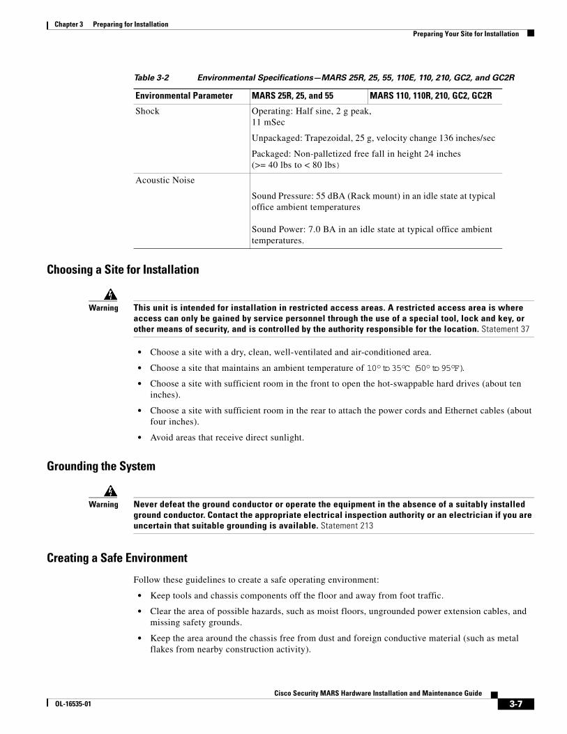
Chapter 3 Preparing for InstallationPreparing Your Site for Installation
Choosing a Site for Installation
Warning This unit is intended for installation in restricted access areas. A restricted access area is where access can only be gained by service personnel through the use of a special tool, lock and key, or other means of security, and is controlled by the authority responsible for the location. Statement 37
• Choose a site with a dry, clean, well-ventilated and air-conditioned area.
• Choose a site that maintains an ambient temperature of 10° to 35°C (50° to 95°F).
• Choose a site with sufficient room in the front to open the hot-swappable hard drives (about ten inches).
• Choose a site with sufficient room in the rear to attach the power cords and Ethernet cables (about four inches).
• Avoid areas that receive direct sunlight.
Grounding the System
Warning Never defeat the ground conductor or operate the equipment in the absence of a suitably installed ground conductor. Contact the appropriate electrical inspection authority or an electrician if you are uncertain that suitable grounding is available. Statement 213
Creating a Safe Environment
Follow these guidelines to create a safe operating environment:
• Keep tools and chassis components off the floor and away from foot traffic.
• Clear the area of possible hazards, such as moist floors, ungrounded power extension cables, and missing safety grounds.
• Keep the area around the chassis free from dust and foreign conductive material (such as metal flakes from nearby construction activity).
Shock Operating: Half sine, 2 g peak, 11 mSec
Unpackaged: Trapezoidal, 25 g, velocity change 136 inches/sec
Packaged: Non-palletized free fall in height 24 inches (>= 40 lbs to < 80 lbs)
Acoustic Noise
Sound Pressure: 55 dBA (Rack mount) in an idle state at typical office ambient temperatures Sound Power: 7.0 BA in an idle state at typical office ambient temperatures.
Table 3-2 Environmental Specifications—MARS 25R, 25, 55, 110E, 110, 210, GC2, and GC2R
Environmental Parameter MARS 25R, 25, and 55 MARS 110, 110R, 210, GC2, GC2R
3-7Cisco Security MARS Hardware Installation and Maintenance Guide
OL-16535-01

Chapter 3 Preparing for InstallationPrecautions for Rack-Mounting
AC PowerEnsure that the plug-socket combination is accessible at all times, because it serves as the main disconnecting device.
Warning This product requires short-circuit (overcurrent) protection, to be provided as part of the building installation. Install only in accordance with national and local wiring regulations. Statement 1045
CablingUse the cables in the accessory kit to connect the MARS Appliance console port to a console or computer that is running a console program. In addition to using the console cable, use the provided standard Ethernet cable to connect the MARS Appliance to your network. For information on network cable requirements, see Cabling, page 3-8.
Inline Filter for the ModemAn inline filter for line impedance matching is shipped in the Accessory Kit. Insert the male RJ-11 connector of the filter into the Line-in socket of the MARS modem. Insert the local telephone cable into the RJ-11 socket of the filter.
The following countries require the filter to be used with the MARS modem:
Australia, Austria, Belgium, China, Czech Republic, Denmark, Finland, France, Germany, Greece, Hungary, Ireland, Italy, Korea, Luxembourg, Netherlands, Poland, Portugal, Spain, Sweden, and the UK.
Precautions for Rack-Mounting
Warning To prevent bodily injury when mounting or servicing this unit in a rack, you must take special precautions to ensure that the system remains stable. The following guidelines are provided to ensure your safety: Statement 1006
Observe the following precautions for rack stability and safety. Also refer to the rack installation documentation accompanying the rack for specific warning and caution statements and procedures.
Note “Component” refers to any server, storage system, or appliance, and to various peripherals or supporting hardware.
• Do not move large racks by yourself. Due to the height and weight of the rack, a minimum of two people are needed to accomplish this task.
• Ensure that the rack is level and stable before extending a component from the rack.
• Do not overload the AC supply branch circuit that provides power to the rack. The total rack load should not exceed 80% of the branch circuit rating.
• Ensure that proper airflow is provided to components in the rack.
3-8Cisco Security MARS Hardware Installation and Maintenance Guide
OL-16535-01

Chapter 3 Preparing for InstallationPrecautions for Products with Modems, Telecommunications, or Local Area Network Options
• Do not step or stand on any system or component when servicing other systems and components in a rack.
• This unit should be mounted at the bottom of the rack if it is the only unit in the rack.
• When mounting this unit in a partially filled rack, load the rack from the bottom to the top with the heaviest component at the bottom of the rack.
• If the rack is provided with stabilizing devices, install the stabilizers before mounting or servicing the unit in the rack.
Precautions for Products with Modems, Telecommunications, or Local Area Network Options
Observe the following guidelines when working with options:
• Do not connect or use a modem or telephone during a lighting storm. There may be a risk of electrical shock from lightning.
• Never connect or use a modem or telephone in a wet environment.
• Do not plug a modem or telephone cable into the Ethernet connector.
• Disconnect the modem cable before opening a product enclosure, touching or installing internal components, or touching an uninsulated modem cable or jack.
• Do not use a telephone line to report a gas leak while you are in the vicinity of the leak.
Required Tools and EquipmentYou need the following tools and equipment to install the MARS Appliance:
• Number 2 Phillips screwdriver
• Needle-nosed pliers
• Tape measure and level
• Antistatic mat or antistatic foam
• ESD grounding strap
Packaging Contents ChecklistBefore unpacking the MARS Appliance, check the outside of the box for signs of damage from the shipment. If you suspect that the box was damaged during shipment, tell the carrier, and fill out the appropriate damage claims.
While unpacking the MARS Appliance, place the box so that the direction arrows on the box are facing up. Open the top of the box, and lift the appliance clear. Place the MARS Appliance on a clean flat surface. Re-inspect the appliance for damage.
Each appliance ships with the following items:
• One copy of Software License Claim Certificate
• One copy of Cisco Secure MARS Documentation Guide and Warranty
3-9Cisco Security MARS Hardware Installation and Maintenance Guide
OL-16535-01

Chapter 3 Preparing for InstallationPackaging Contents Checklist
• One copy of Regulatory Compliance and Safety Information for the Cisco Security MARS Appliances.
• One MARS Appliance
• One Appliance Recovery DVD
• Rail kit
• Two to four sets of keys (depending on the appliance model)
• One or two standard computer power cords (depending on the appliance model)
• One telephone cable
• One Category 5 (Cat 5) crossover cable
• One serial cable
• One xDSL In-line filter
Review this checklist to ensure that each item is present. Write down the appliance’s serial number and license key and store them in a safe place. The serial number and license keys both appear as labels on the actual appliance.
3-10Cisco Security MARS Hardware Installation and Maintenance Guide
OL-16535-01

Cisco Security MOL-16535-01
C H A P T E R 4
Installing the ApplianceRevised: July 24, 2008, OL-16535-01
Note At the time of Cisco Security MARS Release 6.0.1, the Cisco Security MARS Appliances 20R, 20, 50, 100E, 100, 200, GCM, and GC were no longer orderable, but the hardware installation information is retained in this manual for your reference.
This chapter describes how to unpack and install any Cisco Security Monitoring, Analysis, and Response System Appliance (MARS Appliance). It describes requisite safety information, environmental requirements, how to install in a rack, and how to cable the appliance. It contains the following sections:
• Installation Quick Reference, page 4-1
• Installing the MARS Appliance in a Rack, page 4-2
• Connecting to the AC Power Source, page 4-9
• Connecting Cables, page 4-10
• Powering on the Appliance and Verifying Hardware Operation, page 4-10
Installation Quick ReferenceTable 4-1 provides an overview of the installation and initial configuration process. Following installation and initial configuration, see the following publications for information on how to use a browser and the HTML interface to fully configure your MARS Appliance to provide the security threat mitigation (STM) services you want from this installation:
• Cisco Security MARS Initial Configuration and Upgrade Guide, 6.X
• User Guide for Cisco Security MARS Local and Global Controllers, Release 6.x
• Device Configuration Guide for Cisco Security MARS, Release 6.x
4-1ARS Hardware Installation and Maintenance Guide

Chapter 4 Installing the ApplianceInstalling the MARS Appliance in a Rack
Installing the MARS Appliance in a RackThis section provides instructions for installing the MARS Appliance on a rack in the following subsection:
• Rack-Mounting MARS Appliances 25R, 25, 55, 110R, 110, 210, GC2R, and GC2, page 4-4
• Rack-Mounting MARS Appliances 20, 50, 100, 100e, 200, GC, and GCM, page 4-6
The MARS rail SKU, CS-MARS-X10-RAIL=, contains two Intel Corporation rail kits as follows:
• AXXBASICRAIL13—for all MARS Gen2 models. This basic rail kit supports both threaded hole racks and square hole, enclosed racks, but it does not support non-threaded circular hole racks. Most racks use this kit.
• AXXHERAIL2—for MARS 110R, 110, 210, GC2R, GC2. This fully-extending, sliding, tool-less rail kit uses a hanging adapter that allows you to support non-threaded circular hole racks.
For a two-post installation, you can purchase a center-mount kit from a commercial vendor as follows:
Intel part number AXXBRACKETS—a set of fixed-mount brackets to hard mount the chassis to a rack; supports 4-post mounting and 2-post center mounting.
The rack must be properly secured to the floor, ceiling, or upper wall, and where applicable, to adjacent racks. The rack should be secured using floor and wall fasteners and bracing specified by industry standards.
Before installing the MARS Appliance in a rack, read Preparing Your Site for Installation, page 3-5, to familiarize yourself with the proper site and environmental conditions. Failure to read and follow these guidelines could lead to an unsuccessful installation and possibly damage the system and components. Perform the steps below when installing and servicing the MARS Appliance.
The following rack installation procedures are for the rack rails included with the appliance on a typical rack unit. Because a variety of rack units exist, this is a general guide to connecting the appliance to the rack
When installing and servicing the MARS Appliance:
Table 4-1 Quick Reference
Task References
Use the rack mount kit to install the MARS Appliance in a rack.
Installing the MARS Appliance in a Rack, page 4-2
Connect the MARS Appliance to an AC power source.
Connecting to the AC Power Source, page 4-9
Connect network and console cables. Connecting Cables, page 4-10
Power on the appliance and Verify Operation Powering on the Appliance and Verifying Hardware Operation, page 4-10
Perform initial configuration of the MARS Appliance.
http://www.cisco.com/en/US/docs/security/security_management/cs-mars/6.0/initial/configuration/setup.html
Configure the MARS Appliance to monitor reporting devices.
http://www.cisco.com/en/US/docs/security/security_management/cs-mars/6.0/initial/configuration/setup.html#wp1157238
4-2Cisco Security MARS Hardware Installation and Maintenance Guide
OL-16535-01

Chapter 4 Installing the ApplianceInstalling the MARS Appliance in a Rack
• Disconnect all power and external cables before installing the system.
• Install the system in compliance with your local and national electrical codes:
– United States: National Fire Protection Association (NFPA) 70; United States National Electrical Code.
– Canada: Canadian Electrical Code, Part, I, CSA C22.1.
– Other countries: If local and national electrical codes are not available, see IEC 364, Part 1 through Part 7.
• Do not work alone under potentially hazardous conditions.
• Do not perform any action that creates a potential hazard to people or makes the equipment unsafe.
• Do not install the MARS Appliance in a rack that has not been securely anchored in place. Damage to the system and personal injury may result.
• Due to the size and weight of the computer system, never install the computer system by yourself.
See Precautions for Rack-Mounting, page 3-8, for additional safety information on rack installation.
A rack is measured in rack units (RUs). An RU is equal to 44 mm or 1.75 inches. MARS Appliances require the following rack space:
Warning To prevent bodily injury when mounting or servicing this unit in a rack, you must take special precautions to ensure that the system remains stable. The following guidelines are provided to ensure your safety:
• This unit should be mounted at the bottom of the rack if it is the only unit in the rack.
• When mounting this unit in a partially filled rack, load the rack from the bottom to the top with the heaviest component at the bottom of the rack.
• If the rack is provided with stabilizing devices, install the stabilizers before mounting or servicing the unit in the rack. Statement 1006
Table 4-2 Appliance Dimensions in Rack Units
Model Dimensions1
1. A rack unit (RU) is a standardized measure for the height of rack-mountable equipment. One RU is 44.45 mm (1.75 in) high, 482.6 mm (19 in.) wide.
MARS 20R, 20 1RU x 16" (41 cm)
MARS 50 1RU x 25.6" (65.0 cm)
MARS 25R, 25 1 RU x 20 in. (D) x 19 in. (W)
MARS 55 1 RU x 25.5 in. (D) x 19 in. (W)
MARS 100 and 100e 3RU x 25.6" (65.0 cm)
MARS 200, GC, and GCm 4RU x 25.6" (65.0 cm)
MARS 110R, 110, 210, GC2R, and GC2 2RU x 27.75 in (704.8 mm)
4-3Cisco Security MARS Hardware Installation and Maintenance Guide
OL-16535-01

Chapter 4 Installing the ApplianceInstalling the MARS Appliance in a Rack
Rack-Mounting MARS Appliances 25R, 25, 55, 110R, 110, 210, GC2R, and GC2Instructions for installing your chassis on a four-post, 19-inch rack are included in the rail kits that shipped with your MARS Appliance.
The following procedures are provided for your reference:
• Installing the Chassis Handles, page 4-4
• Basic Rail Rack-Mount Installation, page 4-5
• Basic Rail Rack-Mount Removal, page 4-5
Caution When mounting this unit in a partially filled rack, load the rack from the bottom to the top with the heaviest component at the bottom of the rack.
Installing the Chassis Handles
The chassis handles enable you to easily push and pull the chassis on the rack rails. To install the chassis handles do the following:
Step 1 Remove the front bezel.
Step 2 Align the chassis handle with the two holes on the side of the MARS Appliance, as shown in Figure 4-1.
Figure 4-1 Installing a Chassis Handle on a MARS 25R, 25, 55, 110R, 110, 210, GC2R or GC2
Step 3 Attach the chassis handle to the MARS Appliance with two screws as shown in Figure 4-1.
Step 4 Install the chassis handle on the other side of the MARS Appliance.
Step 5 Replace the front bezel.
End of Procedure
19
16
62
4-4Cisco Security MARS Hardware Installation and Maintenance Guide
OL-16535-01

Chapter 4 Installing the ApplianceInstalling the MARS Appliance in a Rack
Basic Rail Rack-Mount Installation
Step 1 Extend the inner rail until it locks.
Step 2 Depress the spring safety lock to release the inner rail.
Step 3 Remove the inner rail from the rail assembly.
Step 4 Attach the outer rail slides to the rack posts using two #10-32 x 1/2 screws at the front posts, and two #10-32 x 1/2 screws at the rear posts.
Note The rail flanges mount to the inside of each post.
Step 5 Insert the inner rails over the server chassis sidewall studs.
Step 6 Slide the inner rails toward the front of the server chassis.
Step 7 Secure the inner rails with one #6-32 x 1/4 screw for each rail.
Step 8 Align the inner rails (attached to the server chassis) with the outer rail assemblies (attached to the rack).
Step 9 Engage the matching rails and slide the server chassis into the rack until the two safety stops lock into position.
Step 10 Depress the two safety locks (one on each side).
Step 11 Slide the server chassis all the way into the rack.
Step 12 Use the rack screws (#10-32 x 3/4) to secure the chassis and rack handles into the rack.
End of Procedure
Basic Rail Rack-Mount Removal
Step 1 Disconnect all cables from the back of the system.
Tip You can use the system LED to properly identify the system you are servicing.
Step 2 Pull the appliance from rack until brackets are fully extended.
Step 3 Push in both clips on the brackets and slide the system forward until the inner rail separates from the outer rail.
End of Procedure
4-5Cisco Security MARS Hardware Installation and Maintenance Guide
OL-16535-01

Chapter 4 Installing the ApplianceInstalling the MARS Appliance in a Rack
Rack-Mounting MARS Appliances 20, 50, 100, 100e, 200, GC, and GCMThe rack rail components are shown in Figure 4-2:
Figure 4-2 Rack Rail Components
To install the MARS Appliance in a rack, follow these steps:
Step 1 Prepare inner and outer rails for installation:
a. Remove both inner rails (1) from the outer rails (2) by pressing the latch and pulling them out of the outer channels (Figure 4-3). Set inner rails aside for use in Step 3.
Part number Part Description Quantity
1 Inner rail 2
2 Outer rail 2
3 L-shaped mount brackets (front) 2
4 L-shaped mount brackets (rear) 2
5 Screws bag
6 L-shaped fastening plate 4
1908
70
1
2 4
3
5
6
4-6Cisco Security MARS Hardware Installation and Maintenance Guide
OL-16535-01
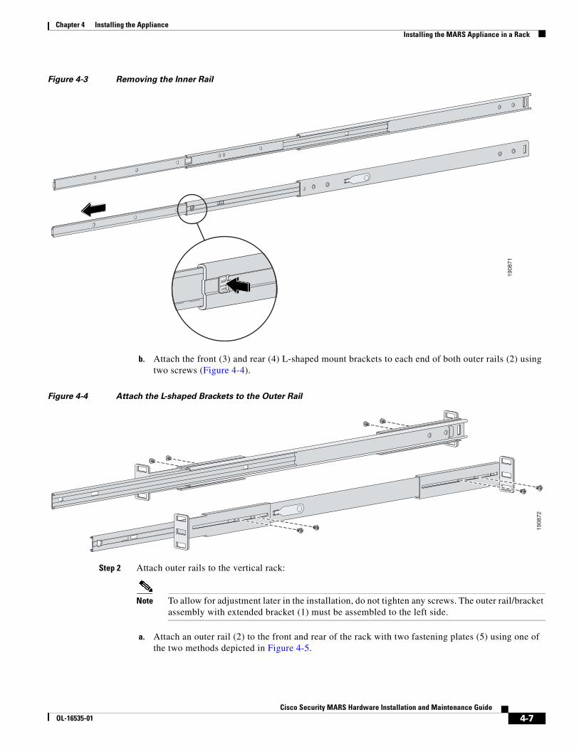
Chapter 4 Installing the ApplianceInstalling the MARS Appliance in a Rack
Figure 4-3 Removing the Inner Rail
b. Attach the front (3) and rear (4) L-shaped mount brackets to each end of both outer rails (2) using two screws (Figure 4-4).
Figure 4-4 Attach the L-shaped Brackets to the Outer Rail
Step 2 Attach outer rails to the vertical rack:
Note To allow for adjustment later in the installation, do not tighten any screws. The outer rail/bracket assembly with extended bracket (1) must be assembled to the left side.
a. Attach an outer rail (2) to the front and rear of the rack with two fastening plates (5) using one of the two methods depicted in Figure 4-5.
1908
71
1908
72
4-7Cisco Security MARS Hardware Installation and Maintenance Guide
OL-16535-01
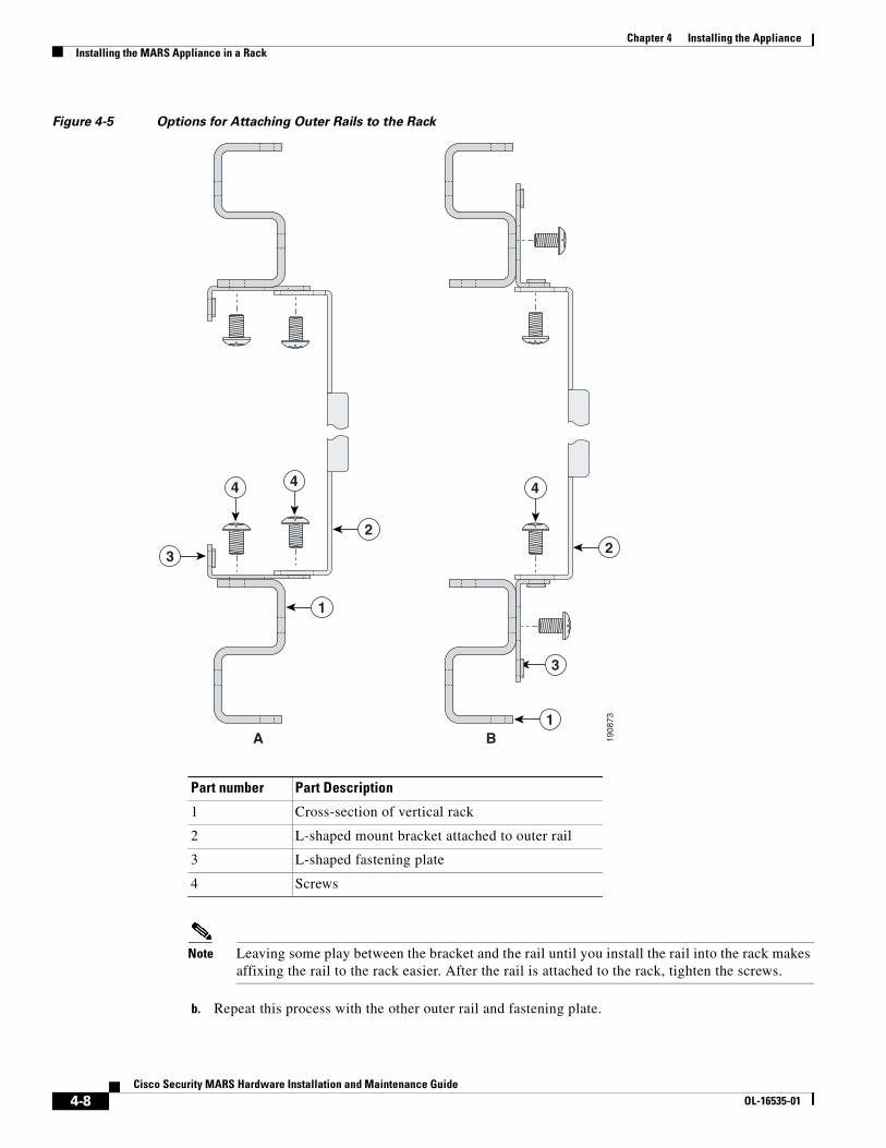
Chapter 4 Installing the ApplianceInstalling the MARS Appliance in a Rack
Figure 4-5 Options for Attaching Outer Rails to the Rack
Note Leaving some play between the bracket and the rail until you install the rail into the rack makes affixing the rail to the rack easier. After the rail is attached to the rack, tighten the screws.
b. Repeat this process with the other outer rail and fastening plate.
Part number Part Description
1 Cross-section of vertical rack
2 L-shaped mount bracket attached to outer rail
3 L-shaped fastening plate
4 Screws
1908
73
2
3
4 4
3
1
2
1
4
A B
4-8Cisco Security MARS Hardware Installation and Maintenance Guide
OL-16535-01
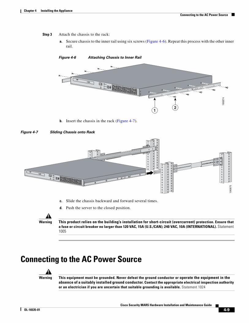
Chapter 4 Installing the ApplianceConnecting to the AC Power Source
Step 3 Attach the chassis to the rack:
a. Secure chassis to the inner rail using six screws (Figure 4-6). Repeat this process with the other inner rail.
Figure 4-6 Attaching Chassis to Inner Rail
b. Insert the chassis in the rack (Figure 4-7).
Figure 4-7 Sliding Chassis onto Rack
c. Slide the chassis backward and forward several times.
d. Push the server to the closed position.
Warning This product relies on the building’s installation for short-circuit (overcurrent) protection. Ensure that a fuse or circuit breaker no larger than 120 VAC, 15A (U.S./CAN); 240 VAC, 10A (INTERNATIONAL). Statement 1005
Connecting to the AC Power Source
Warning This equipment must be grounded. Never defeat the ground conductor or operate the equipment in the absence of a suitably installed ground conductor. Contact the appropriate electrical inspection authority or an electrician if you are uncertain that suitable grounding is available. Statement 1024
RST
PWR
HDD
LAN
+
1908
74
12
1908
75
RST
PWR
HDD
LAN
+
4-9Cisco Security MARS Hardware Installation and Maintenance Guide
OL-16535-01

Chapter 4 Installing the ApplianceConnecting Cables
Connect the AC power receptacle to the AC power source with the provided power cable. Some units have two power cables, one for each AC power receptacle in the appliance.
Connecting CablesUse unshielded twisted pair (UTP) copper wire Ethernet cable, with standard RJ-45 compatible plugs, to connect the MARS Appliance to the network.
Observe the following cabling restrictions for 10BASE-T, 100BASE-TX, and 1000BASE-TX networks:
• For 10BASE-T networks, use Category 3 or greater wiring and connectors.
• For 100BASE-TX and 1000BASE-TX networks, use Category 5 or greater wiring and connectors.
• The maximum cable run length is 328 feet or 100 meters.
Your MARS Appliance comes with one or two standard computer power cords, a Cat 5 crossover cable, Inline Filter for the Modem, page 3-8, and a telephone cable. The telephone jack is required to enable pager- and SMS-based alerts from MARS Appliance.
Warning Do not work on the system or connect or disconnect cables during periods of lightning activity. Statement 1001
To connect the cables:
Step 1 Plug the network connection into the Ethernet port 0 (eth0). To identify the eth0 port, see the back panel diagram of your MARS Appliance in one of the following chapters:
• Physical Descriptions—MARS 25R, 25, 55, 110R, 110, 210, GC2R, and GC2
• Physical Descriptions—MARS 20R, 20, 50, 100E, 100, 200, GCm, and GC
Connect the other end of the cable to an RJ-45 port on a hub or other device, depending on your network configuration.
Step 2 To use the built-in modem, connect the appliance’s line-in jack to a telephone jack using the provided telephone cable. Insert the male RJ-11 connector of the inline impedance matching filter into the line-in socket of the MARS modem. Insert the local telephone cable into the RJ-11 socket of the filter.
The line-in socket is labeled with a socket icon, the external telephone socket is labeled with a telephone icon. See the “Inline Filter for the Modem” section on page 3-8 for a list of countries that require the filter.
Step 3 Connect a console to the console/serial port using the one of the options described in Establishing a Console Connection. You can also establish more than one console connection.
Powering on the Appliance and Verifying Hardware OperationBefore powering on the appliance, verify that all the cables and cords are firmly seated in their jacks and sockets. Make sure that the vents for the appliance’s fans have sufficient clearance and that the appliance’s air intakes are not blocked.
4-10Cisco Security MARS Hardware Installation and Maintenance Guide
OL-16535-01

Chapter 4 Installing the ApplianceWhat To Do Next
Caution If you hear a loud beeping sound after turning on the appliance, check the rear panel and make sure that all appliance power supply switches are fully clicked into the ON position. If all switches are locked into the ON position, and you continue to hear the beeping, a power supply might not be functioning. Turn off the appliance’s power and contact Cisco Support.
MARS Appliances 20R, 20, 50, 100E, 100, 200, GCM, and GC
Step 1 Press the appliance’s power supply switches on the back panel of the appliance to the ON position (some models have a single switch).
Step 2 Open the front panel by unscrewing the screw latches at the upper corners.
Step 3 Press the main power switch on the front panel of the appliance to the ON position.
The MARS Appliance takes a couple of minutes to start. The blue power indicator light tells you if it is running. Each hot swappable hard drive should have a green indicator light lit. The unit should be reasonably quiet, with no abnormal sounds.
MARS Appliances 25R, 25, 55, 110R, 110, 210, GC2R, and GC2
Step 1 Verify that the power cables are connected to the power supplies and to a live AC power source.
Step 2 Press the Power button on the control panel.
The System Status LED flashes alternately amber and green for approximately 15 to 20 seconds, then glows steady green when the system is operational. To interpret LEDs, see the following:
• Control Panel LED Descriptions—MARS 25R and 25, page 1-9
• Control Panel LED Descriptions—MARS 55, page 1-11
• Control Panel LED Descriptions—MARS 110R, 110, 210, GC2R, and GC2, page 1-15
What To Do NextWhen the MARS Appliance has powered up, start the software configuration process as described in the Cisco Security MARS Initial Configuration and Upgrade Guide, 6.X, at the following URL:
http://www.cisco.com/en/US/docs/security/security_management/cs-mars/6.0/initial/configuration/initconfig6x.html
4-11Cisco Security MARS Hardware Installation and Maintenance Guide
OL-16535-01

Chapter 4 Installing the ApplianceWhat To Do Next
4-12Cisco Security MARS Hardware Installation and Maintenance Guide
OL-16535-01

Cisco Security MOL-16535-01
C H A P T E R 5i
Hardware Maintenance Tasks—MARS 55, 110R, 110, 210, GC2R, and GC2
Revised: September 8, 2008, OL-16535-01
This chapter contains the following sections”
• Field Replaceable Units, page 5-1
• Removing and Replacing the Front Bezel, page 5-2
• Removing the Chassis Cover, page 5-3
• Replacing the RAID Battery Backup Unit, page 5-4
• Replacing the System Battery, page 5-7
• Hard Drive Troubleshooting and Replacement, page 5-8
• Hot-swapping a Power Supply Unit, page 5-21
• Installing the Inline Modem Filter, page 5-22
• Diagnostic Beep Codes, page 5-22
Field Replaceable UnitsTable 5-1 lists the field replaceable units (FRUs) supported for the MARS 55, 110R, 110, 210, GC2R, and GC2 appliances.
Table 5-1 List of Field Replaceable Units for the Cisco Security MARS Appliances 6.X
FRU Description FRU Part Number
SR2500 (Driskill 2) 750 Watt Power Supply Module CS-MARS-D750-PS =
500 GB SATA-IO Hard Drive (MARS 55) CS-MARS-H500-HD =
500 GB SATA-IO Hard Drive (MARS 110R, 110) CS-MARS-S500-HD =
750 GB SATA-IO Hard Drive CS-MARS-S750-HD =
RAID Controller Back-Up Battery Unit CS-MARS-X10-BB =
Rack-mount Kit CS-MARS-X10-RAIL=
5-1ARS Hardware Installation and Maintenance Guide

Chapter 5 Hardware Maintenance Tasks—MARS 55, 110R, 110, 210, GC2R, and GC2
Removing and Replacing the Front BezelFor the MARS 55, 110R, 110, 210, GC2, and GC, you must remove the front bezel to access the DVD ROM, hard drives, and control panel buttons. The bezel does not lock. The MARS 25R and 25 front panel features are accessible without removing the bezel.
MARS 55
To remove the MARS 55 bezel, support the left-side hinge with your hand, pull the bezel from the right-hand side, swing open, then gently detach left-hand side from hinge, as shown in Figure 5-1.
Figure 5-1 Removing the Front Bezel from a MARS 55
MARS 110R, 110, 210, GC2R, and GC2
To remove the bezel, pull the bezel from the appliance, as shown in Figure 5-2.
To replace the bezel, line up the center notch on the bezel with the center guide on the rack handles, then push the bezel onto the front of the MARS Appliance until it clicks into place.
!1
2
Cisco Security MARS 55 Series
27
05
30
5-2Cisco Security MARS Hardware Installation and Maintenance Guide
OL-16535-01

Chapter 5 Hardware Maintenance Tasks—MARS 55, 110R, 110, 210, GC2R, and GC2
Figure 5-2 Removing the Front Bezel
Removing the Chassis CoverThis section pertains only to the MARS 110R, 110, 210, GC2R, and GC2 appliances.
The MARS Appliance must be operated with the chassis cover in place to ensure proper cooling. Remove the top cover to add or replace components inside of the appliance. Before removing the chassis cover, power down the appliance and unplug all peripheral devices and the AC power cables.
Note A nonskid surface or a stop behind the MARS Appliance may be needed to prevent the MARS Appliance from sliding on your work surface.
Removing the Chassis Cover
Step 1 Observe all safety and ESD precautions. See “Safety Information” section on page 5-22.”
Step 2 Turn off the appliance.
Step 3 Disconnect the AC power cords.
Step 4 Remove the safety screw if it is installed, as shown in callout A of Figure 3.
Step 5 While holding in the blue button at the top of the MARS Appliance (callout B), slide the top cover back until it stops, as shown in callout C of Figure 3.
Step 6 Insert your finger in the notch shown in callout D of Figure 3, then lift the cover upward to remove it.
19
16
71
5-3Cisco Security MARS Hardware Installation and Maintenance Guide
OL-16535-01

Chapter 5 Hardware Maintenance Tasks—MARS 55, 110R, 110, 210, GC2R, and GC2
Figure 3 Removing the MARS Appliance Cover
End of Procedure
Replacing the Chassis Cover
Step 1 Place the cover over the MARS Appliance so that the side edges of the cover sit just inside the MARS Appliance sidewalls.
Step 2 Slide the cover forward until it clicks into place.
Step 3 (Optional) Insert the safety screw at the center of the top cover if required.
Step 4 Reconnect the AC power cords.
End of Procedure
Replacing the RAID Battery Backup Unit This section pertains only to the MARS 110R, 110, 210, GC2R, and GC2 appliances.
RAID Controller Back-Up Battery Part number: CS-MARS-X10-BB=
The RAID Backup Battery Unit (RAID BBU) prevents RAID data loss by preserving data held in the RAID cache module during a power outage. The RAID BBU can provide up to 72 hours of battery power until the system power is restored.
The RAID BBU requires 24 hours to fully charge from when the appliance is first powered on, and is continually charged thereafter from the system power. The total charge capacity of the battery degrades over time. The show healthinfo CLI command reports the relative charge state of the RAID BBU.
AD
C
B
19
16
69
5-4Cisco Security MARS Hardware Installation and Maintenance Guide
OL-16535-01

Chapter 5 Hardware Maintenance Tasks—MARS 55, 110R, 110, 210, GC2R, and GC2
There is a direct relationship between the relative charge and the battery backup time (100%charge = 72hours). A 100 percent charge provides 72 hours RAID cache protection. Similarly, a 75 percent charge provides 54 hours of protection (100%charge * .75 = 72hours * .75).
Make sure there is sufficient charge to provide RAID cache protection for the total probable hours the MARS Appliance could be without system power. For example, a 90.3% charge (65 hours) would allow 2 hours to manually restore system power if a total power outage occurred in an unattended facility between 17h00 Friday to 8h00 Monday (63 hours).
Example 5-1 displays BBU status information in an excerpt of the show healthinfo CLI command.
Example 5-1 RAID Battery Backup Unit show healthinfo Command Output
[pnadmin]$ show healthinfo <snip>BBU information : Relative state of charge : 93 %Full charge capacity : 920 mAhRemain capacity : 858 mAh
<snip>
Summary of steps required to replace the RAID BBU:
1. Remove the chassis cover.
2. Remove the large air baffle.
3. Remove the RAID BBU.
4. Install the replacement RAID BBU.
5. Replace the large air baffle.
6. Replace the chassis cover.
Procedure to Replace the Raid Battery Backup Unit
Remove the Cover
Step 1 Observe all safety and ESD precautions. See “Safety Information” section on page 5-22.
Step 2 Power down the appliance and unplug all the AC power cables.
Step 3 Remove the chassis cover. For instructions, see the “Removing the Chassis Cover” section on page 5-3.
Remove the Large Air Baffle
Step 4 Write down how the cables are routed over and under the air baffle (if any). You will need to re-route these cables.
Step 5 Pull up on the air baffle to remove it, as shown in Figure 4. You may need to remove or hold cables out of the way.
5-5Cisco Security MARS Hardware Installation and Maintenance Guide
OL-16535-01
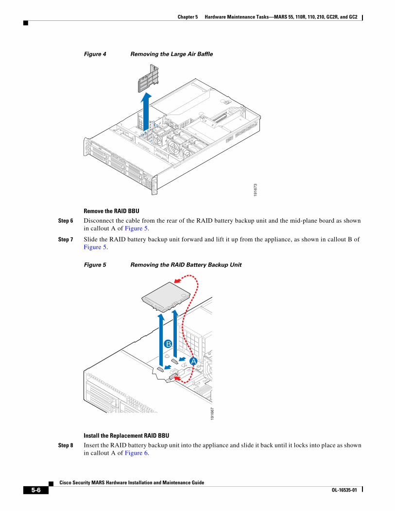
Chapter 5 Hardware Maintenance Tasks—MARS 55, 110R, 110, 210, GC2R, and GC2
Figure 4 Removing the Large Air Baffle
Remove the RAID BBU
Step 6 Disconnect the cable from the rear of the RAID battery backup unit and the mid-plane board as shown in callout A of Figure 5.
Step 7 Slide the RAID battery backup unit forward and lift it up from the appliance, as shown in callout B of Figure 5.
Figure 5 Removing the RAID Battery Backup Unit
Install the Replacement RAID BBU
Step 8 Insert the RAID battery backup unit into the appliance and slide it back until it locks into place as shown in callout A of Figure 6.
19
16
73
A
B
19
16
67
5-6Cisco Security MARS Hardware Installation and Maintenance Guide
OL-16535-01
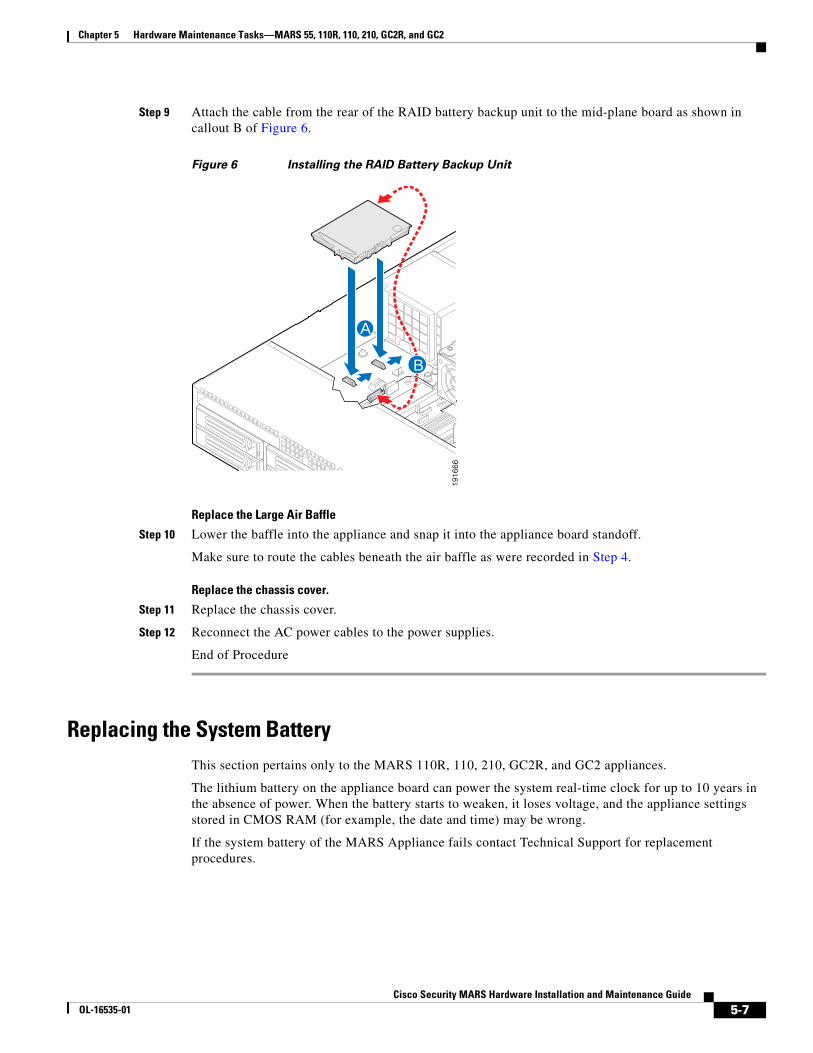
Chapter 5 Hardware Maintenance Tasks—MARS 55, 110R, 110, 210, GC2R, and GC2
Step 9 Attach the cable from the rear of the RAID battery backup unit to the mid-plane board as shown in callout B of Figure 6.
Figure 6 Installing the RAID Battery Backup Unit
Replace the Large Air Baffle
Step 10 Lower the baffle into the appliance and snap it into the appliance board standoff.
Make sure to route the cables beneath the air baffle as were recorded in Step 4.
Replace the chassis cover.
Step 11 Replace the chassis cover.
Step 12 Reconnect the AC power cables to the power supplies.
End of Procedure
Replacing the System Battery This section pertains only to the MARS 110R, 110, 210, GC2R, and GC2 appliances.
The lithium battery on the appliance board can power the system real-time clock for up to 10 years in the absence of power. When the battery starts to weaken, it loses voltage, and the appliance settings stored in CMOS RAM (for example, the date and time) may be wrong.
If the system battery of the MARS Appliance fails contact Technical Support for replacement procedures.
A
B
19
16
66
5-7Cisco Security MARS Hardware Installation and Maintenance Guide
OL-16535-01
Chapter 5 Hardware Maintenance Tasks—MARS 55, 110R, 110, 210, GC2R, and GC2
Hard Drive Troubleshooting and ReplacementThis section pertains only to the MARS 55, 110R, 110, 210, GC2R, and GC2 appliances and contains the following subsections:
• Hard Drive Status LEDs, page 5-8
• Partition Checking, page 5-9
• Overview of RAID Subsystem, page 5-9
• Hotswapping Hard Drives, page 5-10
• Viewing RAID Array Status with the raidstatus CLI Command, page 5-11
• Procedure to Hotswap a Hard Drive, page 5-16
• Hotswap CLI Example, page 5-18
• Replacing a Hard Drive in the Hard Drive Carrier, page 5-20
Note Hard drives are also termed HDDs throughout this section.
Cisco Security MARS HDDs are Cisco field replaceable units (FRUs). The following table provides the correct FRU part numbers for your MARS appliance.
Note Hard drives can consume up to 17 watts of power each. Drives are specified to run at a maximum ambient temperature of 45 °C.
Hard Drive Status LEDs
Each HDD has a status LED. A flickering green light indicates activity. The control panel has a status LED that flickers with any HDD activity.
Warning There is the danger of explosion if the battery is replaced incorrectly. Replace the battery only with the same or equivalent type recommended by the manufacturer. Dispose of used batteries according to the manufacturer’s instructions. Statement 1015
MARS Model Hard Drive Descriptions and Part Numbers
CS-MARS-55-K9 500 GB SATA-IO Hard Drive Part number: CS-MARS-H500-HD=
CS-MARS-110R-K9 CS-MARS-110-K9
500 GB SATA-IO Hard Drive Part number: CS-MARS-S500-HD=
CS-MARS-210-K9 CS-MARS-GC2R-K9 CS-MARS-GC2-K9
750 GB SATA-IO Hard Drive Part number: CS-MARS-S750-HD=
5-8Cisco Security MARS Hardware Installation and Maintenance Guide
OL-16535-01

Chapter 5 Hardware Maintenance Tasks—MARS 55, 110R, 110, 210, GC2R, and GC2
Partition Checking
The appliance automatically runs checks on HDD partitions after the system has been re-booted 25–30 times, or if the appliance has not been re-booted in 180 days.
Overview of RAID Subsystem
This section pertains to the following MARS Appliances equipped with a Serial ATA RAID controller card:
• CS-MARS-55-K9
• CS-MARS-110R-K9
• CS-MARS-110-K9
• CS-MARS-210-K9
• CS-MARS-GC2R-K9
• CS-MARS-GC2-K9
Except for the MARS 55, the MARS RAID controller cards operate the hard drives in a RAID 10 configuration, also called RAID 1+0 because it combines the data handling techniques of RAID 1 and RAID 0. The MARS 55 operates as RAID 1 only. For additional information on RAID concepts and terminology, access the following URL: http://en.wikipedia.org/wiki/RAID
RAID 0 Data Striping
In a MARS RAID 10 configuration, half the total number of drives are arrayed as a single logical drive, wherein a data block is distributed across all of the physical drives in the logical drive using RAID 0 striping techniques. Data striping results in better performance for a data intensive application such as MARS, because hard drive random access times are minimized when data is read and written simultaneously from more than one physical hard drive.
Note The MARS 55 does not do RAID 0 striping. It is RAID 1 only.
RAID 1 Mirroring and Subunits
Half the number of drives in the MARS RAID 10 array mirror the RAID 0 virtual drive. Each physical drive in the RAID 0 array is mirrored by an identical physical drive using RAID 1 techniques. Data written to one of the drives within the RAID 0 array is simultaneously written to its dedicated RAID 1 partner, thereby providing fault tolerance through data redundancy. The RAID 1 hard drive pairs are listed in Table 5-4. For the MARS 55, one drive mirrors the other in a simple RAID 1 configuration.
Rebuilding a Degraded Array
Either drive in a RAID 1 pair can serve in place of its partner should either drive become degraded (unavailable, physically inoperative, or data corrupted). A physical drive degraded but still physically operative can be rebuilt from the data of its undegraded partner and rejoin the array. An inoperative physical drive can be replaced with an operative one which is then rebuilt to join the array.
When any physical drive of the RAID 10 array is degraded, the entire array is considered degraded. While the array still functions, it is not working to its optimal throughput or redundancy capacity.
5-9Cisco Security MARS Hardware Installation and Maintenance Guide
OL-16535-01
Chapter 5 Hardware Maintenance Tasks—MARS 55, 110R, 110, 210, GC2R, and GC2
In a degraded RAID 10 array, data destined for a degraded physical drive is written to available space on the RAID 1 partner until the degraded drive can be rebuilt or replaced. Degraded drives are rebuilt in sequence, one rebuilding process must complete before the next process can begin. Between 200 and 300 minutes are required to rebuild a RAID 1 subunit.
Hotswapping Hard Drives
This section pertains only to the MARS 55, 110R, 110, 210, GC2R, and GC2 appliances.
An HDD can be hotswapped, that is, replaced without rebooting the MARS appliance. The hotswap actions can be summarized in the following five steps. The detailed procedure is in the section, Procedure to Hotswap a Hard Drive.
1. Establish a console connection to the MARS appliance.
2. Enter the raidstatus command to determine the status and the chassis HDD slot number of the HDD to hotswap.
3. Execute a hotswap remove disk command, then remove the HDD.
4. Execute a hotswap add disk command then insert the replacement HDD.
5. Enter the raidstatus command to monitor the progress of the replacement HDD as it is rebuilt.
Use the raidstatus CLI command to view the status of the RAID array (virtual disk) and of the individual HDDs. Table 5-2 lists the status conditions that require an HDD to be hotswapped. These status conditions cause MARS to send an email alert to the administrator.
Caution Always use the hotswap remove disk CLI command before you remove a hard drive and hotswap add disk before you insert a hard drive. The disk argument is the hard drive slot number. Use the hotswap list all command to view the slot number to Port and PD number map.
The rebuilding process duration is between 200 and 300 minutes, depending on CPU load.
Note To match original performance, hotswapped HDDs should be the same make, model and size as the original HDDs.
Caution The RAID 10 array will not function if both HDDs of any RAID 1 pair are removed or corrupted.
Table 5-2 HDD Actions for MARS 55, 110R, 110, 210, GC2R, and GC2
Hard Drive Status1 Possible Cause Recommended Action
Failed Unrecoverable error on previously operative HDD.
Hotswap with a new HDD.
Offline The hotswap remove command was executed for this HDD.
Execute a hotswap add on the HDD if the HDD is known to be good.
Unconfigured Good An online HDD was removed and inserted without executing a hotswap command sequence.
Execute a hotswap remove and hotswap add on the HDD.
5-10Cisco Security MARS Hardware Installation and Maintenance Guide
OL-16535-01

Chapter 5 Hardware Maintenance Tasks—MARS 55, 110R, 110, 210, GC2R, and GC2
Failed Hard Drive Alert
MARS sends and email alert when the hard drive status changes from Online to Failed, Offline, Unconfigured Good, Unconfigured Bad, or N/A. Example 5-2 displays the contents of an e-mail alert sent to the administrator for a failed HDD. In the alert, the DISK number is the same as the chassis HDD slot or raidstatus PD number.
Example 5-2 MARS Hard Drive Replacement Alert
From: [email protected] [mailto:[email protected]]Sent: Tuesday, March 20, 2007 12:22 PMTo: Liu Bang (liubang)Subject: Hard disk failure (host: SJ-LC-86, disk No.: 4)Importance: High
Hard disk failure: RAID error------------------------- HOST : SJ-LC-86 DISK : 4 STATUS : FAILED MODEL : ST3750640NS SIZE : 750GBs
Hard disk 4 on adapter a0 has failed. As a result, the disk array on adapter a0 is running in degrade mode and is no longer fault tolerant. Please replace hard disk 4 as soon as possible. Instructions for doing so can be found in the user's manual.
Viewing RAID Array Status with the raidstatus CLI Command
This section pertains only to the MARS 55, 110R, 110, 210, GC2R, and GC2 appliances.
Example 5-3 displays the output of the raidstatus command executed on a Local Controller 55. Example 5-4 displays the output of the raidstatus command executed on a Local Controller 210. Table 5-3 describes the raidstatus command output fields.
Example 5-3 MARS raidstatus CLI Command Output for MARS 55
[pnadmin]$ raidstatusRAID Controller Information: -------------------------------------------------------Product Name : Intel Embedded Server RAID TechnologyDriver Version : 05.08yController Type : SATA
Adapter Raid Type Status Stripe Size
Unconfigured Bad An online HDD was removed or inserted without executing a hotswap sequence and the HDD has a media error.
Hotswap with a new HDD.
N/A The HDD slot is empty. Insert a new HDD with the hotswap add command.
1. For the MARS 55, only the Failed status and Recommend Action is applicable, the other error messages will not appear.
Table 5-2 HDD Actions for MARS 55, 110R, 110, 210, GC2R, and GC2 (continued)
Hard Drive Status1 Possible Cause Recommended Action
5-11Cisco Security MARS Hardware Installation and Maintenance Guide
OL-16535-01
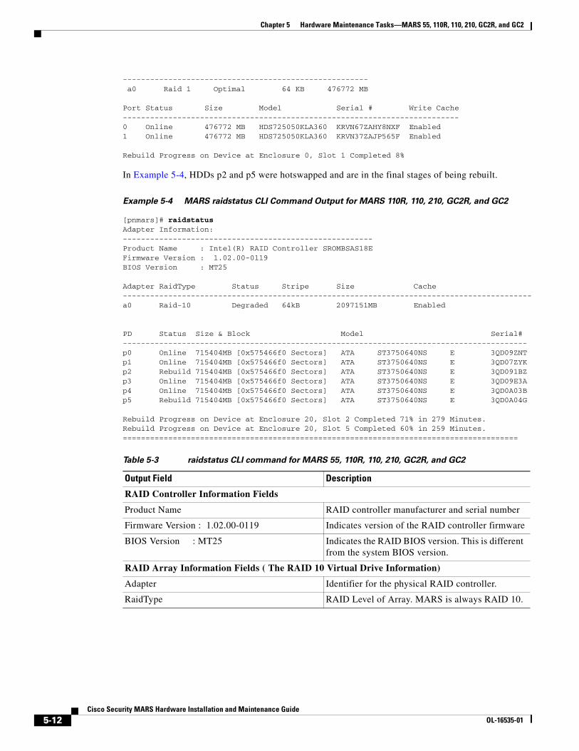
Chapter 5 Hardware Maintenance Tasks—MARS 55, 110R, 110, 210, GC2R, and GC2
------------------------------------------------------ a0 Raid 1 Optimal 64 KB 476772 MB
Port Status Size Model Serial # Write Cache --------------------------------------------------------------------------0 Online 476772 MB HDS725050KLA360 KRVN67ZAHY8NXF Enabled 1 Online 476772 MB HDS725050KLA360 KRVN37ZAJP565F Enabled
Rebuild Progress on Device at Enclosure 0, Slot 1 Completed 8%
In Example 5-4, HDDs p2 and p5 were hotswapped and are in the final stages of being rebuilt.
Example 5-4 MARS raidstatus CLI Command Output for MARS 110R, 110, 210, GC2R, and GC2
[pnmars]# raidstatusAdapter Information:-------------------------------------------------------Product Name : Intel(R) RAID Controller SROMBSAS18EFirmware Version : 1.02.00-0119BIOS Version : MT25 Adapter RaidType Status Stripe Size Cache------------------------------------------------------------------------------------------a0 Raid-10 Degraded 64kB 2097151MB Enabled
PD Status Size & Block Model Serial#-----------------------------------------------------------------------------------------p0 Online 715404MB [0x575466f0 Sectors] ATA ST3750640NS E 3QD09ZNTp1 Online 715404MB [0x575466f0 Sectors] ATA ST3750640NS E 3QD07ZYKp2 Rebuild 715404MB [0x575466f0 Sectors] ATA ST3750640NS E 3QD091BZp3 Online 715404MB [0x575466f0 Sectors] ATA ST3750640NS E 3QD09E3Ap4 Online 715404MB [0x575466f0 Sectors] ATA ST3750640NS E 3QD0A03Bp5 Rebuild 715404MB [0x575466f0 Sectors] ATA ST3750640NS E 3QD0A04G
Rebuild Progress on Device at Enclosure 20, Slot 2 Completed 71% in 279 Minutes.Rebuild Progress on Device at Enclosure 20, Slot 5 Completed 60% in 259 Minutes.=======================================================================================
Table 5-3 raidstatus CLI command for MARS 55, 110R, 110, 210, GC2R, and GC2
Output Field Description
RAID Controller Information Fields
Product Name RAID controller manufacturer and serial number
Firmware Version : 1.02.00-0119 Indicates version of the RAID controller firmware
BIOS Version : MT25 Indicates the RAID BIOS version. This is different from the system BIOS version.
RAID Array Information Fields ( The RAID 10 Virtual Drive Information)
Adapter Identifier for the physical RAID controller.
RaidType RAID Level of Array. MARS is always RAID 10.
5-12Cisco Security MARS Hardware Installation and Maintenance Guide
OL-16535-01

Chapter 5 Hardware Maintenance Tasks—MARS 55, 110R, 110, 210, GC2R, and GC2
Status The current state of the RAID 10 virtual drive.
• Optimal—All component HDDs are operating as configured.
• Degraded—At least one of the component HDDs has failed or is offline. Troubleshooting is advised to prevent possible data loss.
• Offline—The array is not available or is unusable.
Stripe The MARS RAID 10 data stripe is always 64 KB.
Size The available storage in megabytes of the RAID array.
Cache (not displayed for the MARS 55) The MARS RAID 10 array cache is always enabled.
Individual Hard Drive Information Fields
PD or Port (MARS 55) p0–p5. The physical hard drive numbers. 0 or 1 for the MARS 55
Table 5-3 raidstatus CLI command for MARS 55, 110R, 110, 210, GC2R, and GC2 (continued)
Output Field Description
5-13Cisco Security MARS Hardware Installation and Maintenance Guide
OL-16535-01
Chapter 5 Hardware Maintenance Tasks—MARS 55, 110R, 110, 210, GC2R, and GC2
Status
Note Only Online, Failed, Rebuild, and Undefined are supported on the MARS 55.
The current state of the physical HDD.
• Online—The HDD is functioning normally within the RAID 10 array.
• Rebuild—The HDD is being reimaged from its RAID 1 partner to restore full redundancy to a the virtual disk. The RAID 10 array efficiency is not yet optimal.
• Failed—The HDD originally was Online, but now has an unrecoverable error. An email alert is sent to the administrator.
• Offline—The HDD was removed by executing a hotswap remove command, but the HDD was not physically removed from the slot. An email alert is sent to the administrator.
• Unconfigured Good—The HDD is usable, but the RAID information is out of sync with the RAID 1 partner. An email alert is sent to the administrator.
• Unconfigured Bad— The firmware detected a media error on the hard drive. An online HDD was probably removed or inserted without executing a hotswap sequence and the HDD now has a media error. An alert is sent to the administrator.
• Undefined—(MARS 55 only) A new HDD has been added but is not RAID 1 formatted, may appear briefly before “Rebuild.”
• N/A—There is no HDD in the slot. An email alert is sent to the administrator.
Size & Block (not displayed for MARS 55) Size of the usable storage on the HDD
Model The model number of the physical HDD
Serial# The serial number of the physical HDD.
The string, “This drive is foreign” is appended to the serial number when an HDD formatted with metadata from a different RAID controller is introduced. The message is removed when the HDD is assimilated into the array.
Write Cache (MARS 55 only) RAID 1 Write Cache is always enabled.
Progress Messages
Table 5-3 raidstatus CLI command for MARS 55, 110R, 110, 210, GC2R, and GC2 (continued)
Output Field Description
5-14Cisco Security MARS Hardware Installation and Maintenance Guide
OL-16535-01

Chapter 5 Hardware Maintenance Tasks—MARS 55, 110R, 110, 210, GC2R, and GC2
Hard Drive Slot Number Diagrams
Figure 5-7 shows the chassis HDD slot numbers of the MARS 55. Figure 5-8 shows the chassis HDD slot numbers of the MARS 110R, 110, 210, GC2R, and GC2. Table 5-4 shows how slot numbers correspond to PD and Port numbers used in the raidstatus CLI.
Note For Release 5.3.2 and more recent, the hotswap list all CLI command displays the physical slot number to PD and Port Number layout in ASCII art.
Figure 5-7 HDD Slot Numbers —MARS 55
Figure 5-8 HDD Slot Numbers—MARS 110R, 110, 210, GC2R, and GC2
Rebuild Progress on Device at Enclosure 0, Slot 1 Completed 8%
(MARS 55) Indicates the slot number and percentage complete of the physical drive being rebuilt.
Rebuild Progress on Device at Enclosure 20, Slot 2 Completed 71% in 279 Minutes.
Indicates the status, elapsed rebuilding time, and slot number of each physical drive being rebuilt.
Table 5-3 raidstatus CLI command for MARS 55, 110R, 110, 210, GC2R, and GC2 (continued)
Output Field Description
27
05
29
!1
2
Cisco Security MARS 55 Series
10
!1
2 ID
19
16
50
0
1
2
3
4
5
5-15Cisco Security MARS Hardware Installation and Maintenance Guide
OL-16535-01

Chapter 5 Hardware Maintenance Tasks—MARS 55, 110R, 110, 210, GC2R, and GC2
Procedure to Hotswap a Hard Drive
This section pertains only to the MARS 55, 110R, 110, 210, GC2R, and GC2 appliances.
In the hotswap command, the disk parameter is the chassis slot number of the HDD, but the raidstatus command reports physical drive (PD) numbers or Port numbers (MARS 55). To determine the physical location of the slot in the chassis (chassis slot number), see Figure 5-7 or Figure 5-8 or use the hotswap list all command.
To hotswap an HDD, complete the following steps:
Step 1 Remove the front bezel. See the “Removing and Replacing the Front Bezel” section on page 5-2.
Step 2 Establish a console connection with MARS.
Step 3 Identify the slot number of the HDD to replace with the raidstatus command.
Step 4 Enter hotswap remove disk. (where disk is the slot number of the HDD)
A message informs you that it is safe to remove the HDD.
Note Make sure that you remove the correct physical HDD. If you remove the wrong one accidently then reinsert it, that HDD will register as Unconfigured Good (or Failed for MARS 55).
Table 5-4 Mapping HDD Slot Number to raidstatus CLI Command PD number— MARS 55, 110R, 110, 210, GC2R, and GC2
MARS Appliance Storage Capacity1
Chassis HDD Slot to Port or PD Numbers2 RAID 1 Pairs
MARS 55 500GB RAID 1
2 X 500GB SATA-IO 3.0 Gbps HDD 7200 RPM, 16MB Buffer
Hot-Swappable Front Accessible
Slot 0 is Port 0 Slot 1 is Port 1
Slot 0 and Slot 1
MARS 110R, 110 1.5TB RAID 10 6 X 500GB SATA-IO 3.0 Gbps HDD 7200 RPM, 16MB Buffer
Hot-swappable Front accessible
Slot 0 is p0 Slot 1 is p1 Slot 2 is p2 Slot 3 is p3 Slot 4 is p4 Slot 5 is p5
Slot 0 and Slot 1
Slot 2 and Slot 3
Slot 4 and Slot 5
MARS 210, GC2R, GC2 2.0TB3 RAID 10 6 X 750GB SATA-IO 3.0 Gbps HDD 7200 RPM, 16MB Buffer
Hot-swappable Front accessible
1. The stated storage capacity is the sum of the rated capacity of all the hard drives and does reflect bytes reserved for the RAID overhead on each drive.
2. As of Release 5.3.2, the hotswap list all command displays a map of physical slot locations with their Port and PD Numbers
3. Although there is a total of 4.5 TB storage, RAID 10 has a maximum size configuration of 2 TB Redundant, or 4 TB
5-16Cisco Security MARS Hardware Installation and Maintenance Guide
OL-16535-01
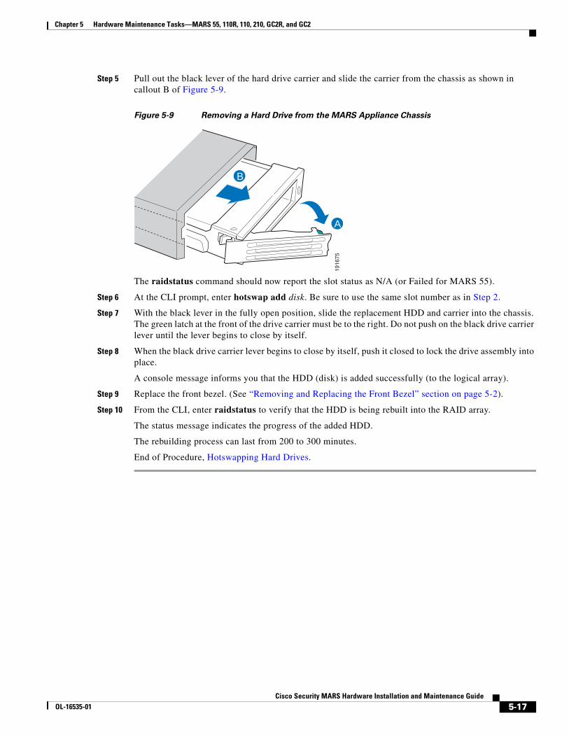
Chapter 5 Hardware Maintenance Tasks—MARS 55, 110R, 110, 210, GC2R, and GC2
Step 5 Pull out the black lever of the hard drive carrier and slide the carrier from the chassis as shown in callout B of Figure 5-9.
Figure 5-9 Removing a Hard Drive from the MARS Appliance Chassis
The raidstatus command should now report the slot status as N/A (or Failed for MARS 55).
Step 6 At the CLI prompt, enter hotswap add disk. Be sure to use the same slot number as in Step 2.
Step 7 With the black lever in the fully open position, slide the replacement HDD and carrier into the chassis. The green latch at the front of the drive carrier must be to the right. Do not push on the black drive carrier lever until the lever begins to close by itself.
Step 8 When the black drive carrier lever begins to close by itself, push it closed to lock the drive assembly into place.
A console message informs you that the HDD (disk) is added successfully (to the logical array).
Step 9 Replace the front bezel. (See “Removing and Replacing the Front Bezel” section on page 5-2).
Step 10 From the CLI, enter raidstatus to verify that the HDD is being rebuilt into the RAID array.
The status message indicates the progress of the added HDD.
The rebuilding process can last from 200 to 300 minutes.
End of Procedure, Hotswapping Hard Drives.
A
B
19
16
75
5-17Cisco Security MARS Hardware Installation and Maintenance Guide
OL-16535-01
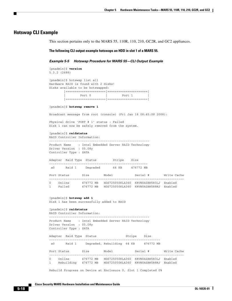
Chapter 5 Hardware Maintenance Tasks—MARS 55, 110R, 110, 210, GC2R, and GC2
Hotswap CLI Example
This section pertains only to the MARS 55, 110R, 110, 210, GC2R, and GC2 appliances.
The following CLI output example hotswaps an HDD in slot 1 of a MARS 55.
Example 5-5 Hotswap Procedure for MARS 55—CLI Output Example
[pnadmin]$ version5.3.2 (2688)
[pnadmin]$ hotswap list all Hardware RAID is found with 2 disks!Disks available to be hotswapped: |======================|======================| | Port 0 | Port 1 | |======================|======================|
[pnadmin]$ hotswap remove 1
Broadcast message from root (console) (Fri Jan 18 08:45:08 2008):
Physical drive 'PORT # 1' status : FailedDisk 1 can now be safely removed from the system.
[pnadmin]$ raidstatusRAID Controller Information: -------------------------------------------------------Product Name : Intel Embedded Server RAID TechnologyDriver Version : 05.08yController Type : SATA
Adapter Raid Type Status Stripe Size ------------------------------------------------------ a0 Raid 1 Degraded 64 KB 476772 MB
Port Status Size Model Serial # Write Cache --------------------------------------------------------------------------0 Online 476772 MB HDS725050KLA360 KRVN0AZBH5R3LJ Enabled 1 Failed 476772 MB HDS725050KLA360 KRVN0AZBH5R8RJ Enabled
[pnadmin]$ hotswap add 1Disk 1 has been successfully added to RAID
[pnadmin]$ raidstatusRAID Controller Information: -------------------------------------------------------Product Name : Intel Embedded Server RAID TechnologyDriver Version : 05.08yController Type : SATA
Adapter Raid Type Status Stripe Size ------------------------------------------------------------- a0 Raid 1 Degraded, Rebuilding 64 KB 476772 MB
Port Status Size Model Serial # Write Cache --------------------------------------------------------------------------0 Online 476772 MB HDS725050KLA360 KRVN0AZBH5R3LJ Enabled 1 Rebuilding 476772 MB HDS725050KLA360 KRVN0AZBH5R8RJ Enabled
Rebuild Progress on Device at Enclosure 0, Slot 1 Completed 0%
5-18Cisco Security MARS Hardware Installation and Maintenance Guide
OL-16535-01
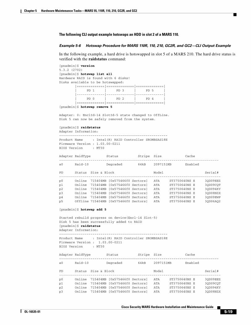
Chapter 5 Hardware Maintenance Tasks—MARS 55, 110R, 110, 210, GC2R, and GC2
The following CLI output example hotswaps an HDD in slot 2 of a MARS 110.
Example 5-6 Hotswap Procedure for MARS 110R, 110, 210, GC2R, and GC2—CLI Output Example
In the following example, a hard drive is hotswapped in slot 5 of a MARS 210. The hard drive status is verified with the raidstatus command:
[pnadmin]$ version5.3.2 (2702)[pnadmin]$ hotswap list allHardware RAID is found with 6 disks!Disks available to be hotswapped: |==============|==============|==============| | PD 1 | PD 3 | PD 5 | |--------------|--------------|--------------| | PD 0 | PD 2 | PD 4 | |==============|==============|==============|[pnadmin]$ hotswap remove 5 Adapter: 0: EnclId-14 SlotId-5 state changed to OffLine.Disk 5 can now be safely removed from the system.
[pnadmin]$ raidstatus Adapter Information: -------------------------------------------------------Product Name : Intel(R) RAID Controller SROMBSAS18EFirmware Version : 1.03.00-0211BIOS Version : MT30
Adapter RaidType Status Stripe Size Cache---------------------------------------------------------------------------------a0 Raid-10 Degraded 64kB 2097151MB Enabled
PD Status Size & Block Model Serial#----------------------------------------------------------------------------------p0 Online 715404MB [0x575466f0 Sectors] ATA ST3750640NS E 3QD09EEZp1 Online 715404MB [0x575466f0 Sectors] ATA ST3750640NS E 3QD09CQTp2 Online 715404MB [0x575466f0 Sectors] ATA ST3750640NS E 3QD094KYp3 Online 715404MB [0x575466f0 Sectors] ATA ST3750640NS E 3QD08NZXp4 Online 715404MB [0x575466f0 Sectors] ATA ST3750640NS E 3QD09EWPp5 Offline 715404MB [0x575466f0 Sectors] ATA ST3750640NS E 3QD06AQ2
[pnadmin]$ hotswap add 5 Started rebuild progress on device(Encl-14 Slot-5)Disk 5 has been successfully added to RAID[pnadmin]$ raidstatusAdapter Information: -------------------------------------------------------Product Name : Intel(R) RAID Controller SROMBSAS18EFirmware Version : 1.03.00-0211BIOS Version : MT30
Adapter RaidType Status Stripe Size Cache---------------------------------------------------------------------------------a0 Raid-10 Degraded 64kB 2097151MB Enabled
PD Status Size & Block Model Serial#----------------------------------------------------------------------------------p0 Online 715404MB [0x575466f0 Sectors] ATA ST3750640NS E 3QD09EEZp1 Online 715404MB [0x575466f0 Sectors] ATA ST3750640NS E 3QD09CQTp2 Online 715404MB [0x575466f0 Sectors] ATA ST3750640NS E 3QD094KYp3 Online 715404MB [0x575466f0 Sectors] ATA ST3750640NS E 3QD08NZX
5-19Cisco Security MARS Hardware Installation and Maintenance Guide
OL-16535-01

Chapter 5 Hardware Maintenance Tasks—MARS 55, 110R, 110, 210, GC2R, and GC2
p4 Online 715404MB [0x575466f0 Sectors] ATA ST3750640NS E 3QD09EWPp5 Rebuild 715404MB [0x575466f0 Sectors] ATA ST3750640NS E 3QD06AQ2
Rebuild Progress on Device at Enclosure 14, Slot 5 Completed 17% in 32 Minutes.
Replacing a Hard Drive in the Hard Drive Carrier
This section pertains only to the MARS 55, 110R, 110, 210, GC2R, and GC2 appliances.
To match original performance, HDDs should be the same make, model and size as the original hard drives.
Step 1 Remove the four screws that attach the hard drive or empty retention device to the drive carrier, as shown in callout A of Figure 5-10.
Two screws are at each side of the retention device or the hard drive. Store the plastic retention device for future use.
Figure 5-10 Removing Hard Drive or Retention Device from Drive Carrier (Retention Device Shown
Here)
Step 2 Remove the hard drive from its wrapper and place it on an antistatic surface.
Step 3 With the hard drive circuit-side down, position the connector end of the drive so that it is facing the rear of the drive carrier, as shown in callout A of Figure 5-11.
Step 4 Align the holes in the drive to the holes in the drive carrier and attach it to the carrier with the screws that were attached to the plastic retention device, as shown in callout B of Figure 5-11.
Figure 5-11 Installing a Hard Drive into a Carrier
A
B
19
16
76
A
B
B
19
16
77
5-20Cisco Security MARS Hardware Installation and Maintenance Guide
OL-16535-01
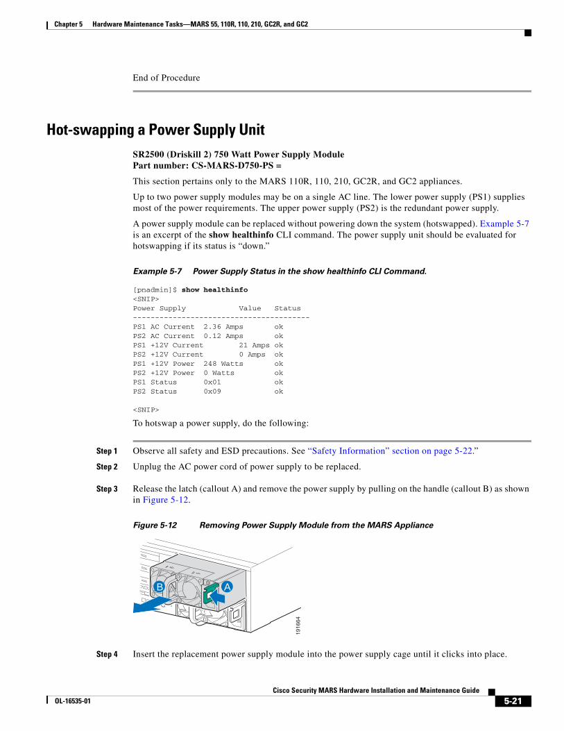
Chapter 5 Hardware Maintenance Tasks—MARS 55, 110R, 110, 210, GC2R, and GC2
End of Procedure
Hot-swapping a Power Supply Unit SR2500 (Driskill 2) 750 Watt Power Supply Module Part number: CS-MARS-D750-PS =
This section pertains only to the MARS 110R, 110, 210, GC2R, and GC2 appliances.
Up to two power supply modules may be on a single AC line. The lower power supply (PS1) supplies most of the power requirements. The upper power supply (PS2) is the redundant power supply.
A power supply module can be replaced without powering down the system (hotswapped). Example 5-7 is an excerpt of the show healthinfo CLI command. The power supply unit should be evaluated for hotswapping if its status is “down.”
Example 5-7 Power Supply Status in the show healthinfo CLI Command.
[pnadmin]$ show healthinfo <SNIP>Power Supply Value Status----------------------------------------PS1 AC Current 2.36 Amps okPS2 AC Current 0.12 Amps okPS1 +12V Current 21 Amps okPS2 +12V Current 0 Amps okPS1 +12V Power 248 Watts okPS2 +12V Power 0 Watts okPS1 Status 0x01 okPS2 Status 0x09 ok
<SNIP>
To hotswap a power supply, do the following:
Step 1 Observe all safety and ESD precautions. See “Safety Information” section on page 5-22.”
Step 2 Unplug the AC power cord of power supply to be replaced.
Step 3 Release the latch (callout A) and remove the power supply by pulling on the handle (callout B) as shown in Figure 5-12.
Figure 5-12 Removing Power Supply Module from the MARS Appliance
Step 4 Insert the replacement power supply module into the power supply cage until it clicks into place.
AB
19
16
64
5-21Cisco Security MARS Hardware Installation and Maintenance Guide
OL-16535-01
Chapter 5 Hardware Maintenance Tasks—MARS 55, 110R, 110, 210, GC2R, and GC2Safety Information
Step 5 Connect the AC power cord to the replacement power supply.
End of Procedure
Installing the Inline Modem FilterAn inline filter for line impedance matching is shipped in the Accessory Kit. The following countries require the filter to be used with the MARS modem:
Australia, Austria, Belgium, China, Czech Republic, Denmark, Finland, France, Germany, Greece, Hungary, Ireland, Italy, Korea, Luxembourg, Netherlands, Poland, Portugal, Spain, Sweden, and the UK.
Insert the male RJ-11 connector of the filter into the line-in socket of the MARS modem. Insert the local telephone cable into the RJ-11 socket of the filter.
The modem line-in socket is labeled with a socket icon, the external telephone socket is labeled with a telephone icon.
Diagnostic Beep CodesTable 5-5 lists Power-on Self Test (POST) error beep codes. Prior to system Video initialization, BIOS uses these beep codes to signal error conditions. The beep code is followed by a user visible code on the POST Progress LEDs (not shown). Beep codes are sounded each time the problem is discovered, such as on each power-up attempt, but they are not sounded continuously. The beep code sequence is read left to right. For example, 4–7 represents four beeps followed by seven beeps.
Safety InformationThese safety instructions apply to all Cisco Security Monitoring, Analysis, and Response System models
Table 5-5 POST Error Beep Codes
Number of Beeps Error Message Description
1, 2, or 3
(3 for MARS 55)
Memory Error Fatal memory error. Reseat the memory or replace the DIMMs with known good modules.
6
(Not applicable to MARS 25R, 25, and 55)
BIOS Error The system has detected a corrupted BIOS in the flash part, and is rolling back to the last good BIOS.
4–7 or 9–11 (Not applicable to MARS 25R, 25, and 55)
System Error Fatal error indicating a possible serious system problem. Contact Technical Support.
8 (Not applicable for MARS 55)
Video Card Error Contact Technical Support.
5-22Cisco Security MARS Hardware Installation and Maintenance Guide
OL-16535-01

Chapter 5 Hardware Maintenance Tasks—MARS 55, 110R, 110, 210, GC2R, and GC2Safety Information
To reduce the risk of bodily injury, electrical shock, fire, and equipment damage, read this section and observe all warnings and precautions before maintaining your Cisco Security MARS appliance.
Intended Application UsesThis product was evaluated as Information Technology Equipment (ITE), which may be installed in offices, schools, computer rooms, and similar commercial type locations. The suitability of this product for other product categories and environments (such as medical, industrial, residential, alarm systems, and test equipment), other than an ITE application, may require further evaluation.
Equipment Handling PracticesReduce the risk of personal injury or equipment damage:
• Conform to local occupational health and safety requirements when moving and lifting equipment.
• Use mechanical assistance or other suitable assistance when moving and lifting equipment.
• To reduce the weight for easier handling, remove any easily detachable components.
Power and Electrical Warnings
Caution The power button, indicated by the stand-by power marking, DOES NOT completely turn off the system AC power, 5V standby power is active whenever the system is plugged in.
Caution Do not attempt to modify or use an AC power cord if it is not the exact type required. A separate AC cord is required for each system power supply.
Caution Some power supplies inCisco Security MARS appliances use Neutral Pole Fusing. To avoid risk of shock use caution when working with power supplies that use Neutral Pole Fusing.
Caution The power supply in this product contains no user-serviceable parts. Do not open the power supply. Hazardous voltage, current and energy levels are present inside the power supply. Return to manufacturer for servicing.
Warning This unit might have more than one power supply connection. All connections must be removed to de-energize the unit. Statement 1028
5-23Cisco Security MARS Hardware Installation and Maintenance Guide
OL-16535-01
Chapter 5 Hardware Maintenance Tasks—MARS 55, 110R, 110, 210, GC2R, and GC2Safety Information
Caution When replacing a hot-plug power supply, unplug the power cord to the power supply being replaced before removing it from the server.
Caution To avoid risk of electric shock, turn off the server and disconnect the power cord, telecommunications systems, networks, and modems attached to the appliance before opening.
Power Cord WarningsIf an AC power cord was not provided with your product, purchase one that is approved for use in your country.
To avoid electrical shock or fire, check the power cords that will be used with the product as follows:
• Do not attempt to modify or use the AC power cord(s) if they are not the exact type required to fit into the grounded electrical outlets
• The power cord(s) must meet the following criteria:
• The power cord must have an electrical rating that is greater than that of the electrical current rating marked on the product.
• The power cord must have safety ground pin or contact that is suitable for the electrical outlet.
• The power supply cord(s) is/are the main disconnect device to AC power. The socket outlet(s) must be near the equipment and readily accessible for disconnection.
• The power supply cord(s) must be plugged into socket-outlet(s) that is /are provided with a suitable earth ground.
System Access WarningsTo avoid personal injury or property damage, the following safety instructions apply whenever accessing the inside of the product:
• Turn off all peripheral devices connected to this product.
• Turn off the system by pressing the power button to off.
• Disconnect the AC power by unplugging all AC power cords from the system or wall outlet.
• Disconnect all cables and telecommunication lines that are connected to the system.
• Retain all screws or other fasteners when removing access cover(s). Upon completion of accessing inside the product, refasten access cover with original screws or fasteners.
• Do not access the inside of the power supply. There are no serviceable parts in the power supply. Return to manufacturer for servicing.
• Power down the appliance and disconnect all power cords before adding or replacing any non hot-plug component.
• When replacing a hot-plug power supply, unplug the power cord to the power supply being replaced before removing the power supply from the appliance.
5-24Cisco Security MARS Hardware Installation and Maintenance Guide
OL-16535-01
Chapter 5 Hardware Maintenance Tasks—MARS 55, 110R, 110, 210, GC2R, and GC2Safety Information
Caution If the appliance has been running, any installed processor(s) and heat sink(s) may be hot. Unless you are adding or removing a hot-plug component, allow the appliance to cool before opening the covers. To avoid the possibility of coming into contact with hot component(s) during a hot-plug installation, be careful when removing or installing the hot-plug component(s).
Caution To avoid injury do not contact moving fan blades. If your system is supplied with a guard over the fan, do not operate the appliance without the fan guard in place.
Rack Mount WarningsThe equipment rack must be anchored to an unmovable support to prevent it from tipping when a server or piece of equipment is extended from it. The equipment rack must be installed according to the rack manufacturer's instructions.
Install equipment in the rack from the bottom up, with the heaviest equipment at the bottom of the rack.
Extend only one piece of equipment from the rack at a time.
You are responsible for installing a main power disconnect for the entire rack unit. This main disconnect must be readily accessible, and it must be labeled as controlling power to the entire unit, not just to the appliance.
To avoid risk of potential electric shock, a proper safety ground must be implemented for the rack and each piece of equipment installed in it.
Electrostatic Discharge (ESD)
Caution ESD can damage disk drives, boards, and other parts. We recommend that you perform all procedures at an ESD workstation. If one is not available, provide some ESD protection by wearing an antistatic wrist strap attached to chassis ground -- any unpainted metal surface -- on your server when handling parts. Always handle boards carefully. They can be extremely sensitive to ESD. Hold boards only by their edges. After removing a board from its protective wrapper or from the server, place the board component side up on a grounded, static free surface. Use a conductive foam pad if available but not the board wrapper. Do not slide board over any surface.
Battery Replacement
Caution Do not attempt to recharge a battery. Do not attempt to disassemble, puncture, or otherwise damage a battery.
5-25Cisco Security MARS Hardware Installation and Maintenance Guide
OL-16535-01
Chapter 5 Hardware Maintenance Tasks—MARS 55, 110R, 110, 210, GC2R, and GC2Safety Information
Cooling and AirflowCarefully route cables as directed to minimize airflow blockage and cooling problems. For proper cooling and airflow, operate the system only with the chassis covers installed. Operating the system without the covers in place can damage system parts.
To install the covers:
• Check first to make sure you have not left loose tools or parts inside the system.
• Check that cables, add-in boards, and other components are properly installed.
• Attach the covers to the chassis according to the product instructions.
Laser Peripherals or Devices To avoid risk of radiation exposure and/or personal injury:
• Do not open the enclosure of any laser peripheral or device
• Laser peripherals or devices have are not user serviceable
• Return to manufacturer for servicing
Warning There is the danger of explosion if the battery is replaced incorrectly. Replace the battery only with the same or equivalent type recommended by the manufacturer. Dispose of used batteries according to the manufacturer’s instructions. Statement 33
5-26Cisco Security MARS Hardware Installation and Maintenance Guide
OL-16535-01
Cisco Security MOL-16535-01
C H A P T E R 6
Hardware Maintenance Tasks—MARS 100E, 100, 200, GCM, and GCRevised: September 8, 2008, OL-16535-01
The MARS Appliance requires little maintenance. To perform maintenance tasks, you can use the CLI or the web interface as needed. Some hardware maintenance tasks require physical access to the MARS Appliance.
• Replacing the Lithium Cell CMOS Battery, page 6-1
• Hard Drive Troubleshooting and Replacement, page 6-1
Replacing the Lithium Cell CMOS BatteryThis section pertains only to the MARS 100, 100E, 200, GCM, and GC appliances.
The lithium battery on the appliance board can power the system real-time clock for up to 10 years in the absence of power. When the battery starts to weaken, it loses voltage, and the appliance settings stored in CMOS RAM (for example, the date and time) may be wrong.
If the system battery of the MARS Appliance fails contact Technical Support for replacement procedures.
Hard Drive Troubleshooting and ReplacementThis section comprises the following subsections:
• Hard Drive Status Lights, page 6-2
Warning There is the danger of explosion if the battery is replaced incorrectly. Replace the battery only with the same or equivalent type recommended by the manufacturer. Dispose of used batteries according to the manufacturer’s instructions. Statement 1015
6-1ARS Hardware Installation and Maintenance Guide

Chapter 6 Hardware Maintenance Tasks—MARS 100E, 100, 200, GCM, and GCHard Drive Troubleshooting and Replacement
• Partition Checking, page 6-2
• Hotswapping Hard Drives, page 6-2
• RAID Procedures for MARS Appliances 100E, 100, 200, GCM, and GC, page 6-3
• Procedures for the MARS RAID Utility, page 6-10
• Hotswap CLI Example, page 6-9
Note The term HDD is sometimes used throughout this section in place of hard disk drive, disk, or hard drive.
Hard Drive Status Lights
Depending on the model of the appliance, each hard drive has two status lights under or next to the drive. The following states can be determined based on the status lights:
• A steady green light indicates that the drive is functioning normally.
• A blinking orange light indicates that the drive is performing I/O operations.
• No light indicates that the disk has no power.
Partition Checking
The appliance automatically runs checks on different partitions of the hard drive after the system has been re-booted 25 to 30 times, or if the appliance has not been re-booted in 180 days.
Hotswapping Hard Drives
If a hard drive fails in the MARS 50, 100, 100e, 200, GC, or GCm appliance models, the MARS administrator receives an e-mail notification. The notification identifies the slot number of the failed hard drive.
Overview of MARS RAID 10 Subsystem
This section pertains only to the MARS 100, 100E, 200, GCM, and GC appliances.
The following MARS Appliances are equipped with a Parallel IDE/ATA Redundant Array of Inexpensive Disks (RAID) controller card:
• CS-MARS-100E-K9
• CS-MARS-100-K9
• CS-MARS-200-K9
• CS-MARS-GCM-K9
• CS-MARS-GC-K9
All other MARS appliances running software version 4.X or prior have software RAID controllers.
The MARS RAID controller cards operate the hard drives in a RAID 10 configuration, also called RAID 1+0 because it combines the data handling techniques of RAID 1 and RAID 0. For additional information on RAID concepts and terminology, access the following URL: http://en.wikipedia.org/wiki/RAID
6-2Cisco Security MARS Hardware Installation and Maintenance Guide
OL-16535-01

Chapter 6 Hardware Maintenance Tasks—MARS 100E, 100, 200, GCM, and GCHard Drive Troubleshooting and Replacement
RAID 0 Data Striping
In a MARS RAID 10 configuration, half the total number of drives are arrayed as a single logical drive, wherein a data block is distributed across all of the physical drives in the logical drive using RAID 0 striping techniques. Data striping results in better performance for a data intensive application such as MARS, because hard drive random access times are minimized when data is read and written simultaneously from more than one physical hard drive.
RAID 1 Mirroring and Subunits
The remaining drives in the MARS RAID 10 array mirror the RAID 0 virtual drive. Each physical drive in the RAID 0 array is mirrored by an identical physical drive using RAID 1 techniques. Data written to one of the drives within the RAID 0 array is simultaneously written to its dedicated RAID 1 partner, thereby providing fault tolerance through data redundancy.
A RAID 1 pair is termed a subunit. For example, an 8-drive Local Controller 200 has 4 RAID 1 subunits (8 drives in total), a 6-drive Local Controller 100 has 3 subunits (6 drives in total).
A subunit always comprises the same two hard drive slots. For instance, a MARS 110 or GC2 will always have the same pairings in a subunit, Slots 0 and 1, physical hard drive pairings
Rebuilding a Degraded Array
Either drive in a subunit can serve in place of its partner should either drive become degraded (unavailable, physically inoperative, or data corrupted). A physical drive degraded but still physically operative can be rebuilt from the data of its undegraded partner and rejoin the array. An inoperative physical drive can be replaced with an operative one which is then rebuilt to join the array.
When any physical drive of the RAID 10 array is degraded, the entire array is considered degraded. While the array still functions, it is not working to its optimal throughput or redundancy capacity.
In a degraded RAID 10 array, data destined for degraded physical drives are written to available space on other subunits until the degraded drives are rebuilt or replaced. Degraded drives are rebuilt in sequence, one rebuilding process must complete before the next process can begin. Between 90 minutes and 2 hours are required to rebuild a MARS subunit. The more data to rebuild, the more time is consumed.
Hotswapping and Field-Replaceable Hard Drives
A physical hard drive can be hotswapped, that is, replaced without rebooting the MARS appliance. Use the hotswap CLI command before removing or inserting a new hard drive.
Note To match original performance, hotswapped hard drives should be the same make, model and size as the original hard drives.
RAID Procedures for MARS Appliances 100E, 100, 200, GCM, and GC
This section pertains only to the MARS 100E, 100, 200, GCM, and GC appliances.
The raidstatus CLI command
The raidstatus CLI command reports the current status of the RAID 10 array. Example 6-1 displays the output of the raidstatus command executed on a Local Controller 200. Table 6-1 describes the relevant output fields.
6-3Cisco Security MARS Hardware Installation and Maintenance Guide
OL-16535-01

Chapter 6 Hardware Maintenance Tasks—MARS 100E, 100, 200, GCM, and GCHard Drive Troubleshooting and Replacement
Example 6-1 Example of raidstatus CLI Command Output
[PNADMIN]$ raidstatus
CONTROLLER: C0-------------DRIVER: 1.02.00.037MODEL: 7506-8FW: FE7X 1.05.00.068BIOS: BE7X 1.08.00.048MONITOR: ME7X 1.01.00.040SERIAL #: L14104A5090383PCB: REV4PCHIP: 1.30-66ACHIP: 3.20
# OF UNITS: 1UNIT 0: RAID 10 931.54 GB ( 1953580032 BLOCKS): REBUILDING (75%)
# OF PORTS: 8PORT 0: WDC WD2500JB-19GVA0 WD-WCAL73129135 232.88 GB (488397168 BLOCKS): OK(UNIT 0)PORT 1: WDC WD2500JB-19GVA0 WD-WCAL73291174 232.88 GB (488397168 BLOCKS): OK(UNIT 0)PORT 2: WDC WD2500JB-19GVA0 WD-WCAL73157538 232.88 GB (488397168 BLOCKS): OK(NO UNIT)PORT 3: WDC WD2500JB-98GVA0 WD-WMAL72243570 232.88 GB (488397168 BLOCKS): OK(UNIT 0)PORT 4: WDC WD2500JB-00GVA0 WD-WCAL73883655 232.88 GB (488397168 BLOCKS): OK(UNIT 0)PORT 5: WDC WD2500JB-19GVA0 WD-WCAL73290905 232.88 GB (488397168 BLOCKS): OK(UNIT 0)PORT 6: WDC WD2500JB-98GVA0 WD-WCAL73693347 232.88 GB (488397168 BLOCKS): OK(UNIT 0)PORT 7: WDC WD2500JB-98GVA0 WD-WMAL72244432 232.88 GB (488397168 BLOCKS): OK(UNIT 0)UNIT /C0/U0---------------------STATUS: REBUILDINGUNIT TYPE: RAID 10STRIPE SIZE: 64KSIZE: 931.54 GB (1953580032 BLOCKS)# OF SUBUNITS: 4
SUBUNIT 0: RAID 1: OK
SUBUNIT 0: CBOD: OKPHYSICAL PORT: 7LOGICAL PORT: 0
SUBUNIT 1: CBOD: OKPHYSICAL PORT: 4LOGICAL PORT: 1
SUBUNIT 1: RAID 1: REBUILDING (1%)
SUBUNIT 0: CBOD: DEGRADEDPHYSICAL PORT: 6LOGICAL PORT: 0
SUBUNIT 1: CBOD: OKPHYSICAL PORT: 3LOGICAL PORT: 1
6-4Cisco Security MARS Hardware Installation and Maintenance Guide
OL-16535-01

Chapter 6 Hardware Maintenance Tasks—MARS 100E, 100, 200, GCM, and GCHard Drive Troubleshooting and Replacement
SUBUNIT 2: RAID 1: DEGRADED
SUBUNIT 0: CBOD: OKPHYSICAL PORT: 5LOGICAL PORT: 0
SUBUNIT 1: CBOD: OKPHYSICAL PORT: 0 LOGICAL PORT: 1SUBUNIT 3: RAID 1: OK
SUBUNIT 0: CBOD: OKPHYSICAL PORT: 1LOGICAL PORT: 0
SUBUNIT 1: CBOD: OKPHYSICAL PORT: 0LOGICAL PORT: 1
Table 6-1 Explanation of Output Fields for raidstatus CLI Command
Output Field DescriptionFW: FE7X 1.05.00.068 Indicates version of controller card firmware.
STATUS: REBUILDING Current status of entire array.
• OK—The array and subunits are in good order and operating at optimal efficiency.
• Rebuilding—A subunit is being rebuilt. Array efficiency is not yet optimal.
• Degraded—At least one physical disk in the array cannot be accessed.
# OF UNITS: 1 UNIT 0: RAID 10 931.54 GB ( 1953580032 BLOCKS): REBUILDING (75%)
Units—Indicates the number of virtual drives the entire RAID configuration represents. In this case, the array acts as one virtual hard drive or unit.
Unit—Identifies the RAID level, array size, and array status statistics of the specified unit. The total array size does not include the RAID overhead bytes. The status may be as follows:
• OK—The array and subunits are in good order and operating at optimal efficiency.
• Rebuilding—A subunit is being rebuilt. Array efficiency is not yet optimal.
• Degraded—At least one physical disk in the array cannot be accessed. Troubleshooting is advised to prevent possible data loss.
# OF PORTS: 8 Indicates the number of hard drives in the array.
6-5Cisco Security MARS Hardware Installation and Maintenance Guide
OL-16535-01
Chapter 6 Hardware Maintenance Tasks—MARS 100E, 100, 200, GCM, and GCHard Drive Troubleshooting and Replacement
Correlating Hard Drive Slots to RAIDSTATUS Command Physical Port Numbers
This section pertains only to the MARS 100E, 100, 200, GCM, and GC appliances.
Figure 6-1 shows how the hard drive slot numbers are ordered in MARS LC-200, GC, or GCM. Hard drive slot numbers increase from left to right, and from top to bottom. Figure 6-2 shows slot numbering for the Local Controller 100 and 100E.
The MARS CLI identifies hard drives by port numbers or physical port numbers, which are logical designations assigned by the operating system. Table 6-2 shows how the hard drive slots in the chassis correspond to the port and physical port numbers as reported in the CLI.
Note A port number is the same as a physical port number.
PORT 0: WDC WD2500JB-19GVA0 WD-WCAL73129135 232.88 GB (488397168 BLOCKS) : OK(UNIT 0)
Indicates the model, serial number, size, and operational status of a hard drive related to the port. If a hard drive is not present or cannot be accessed, this output does not appear for that port.
Table 6-2 lists how hard drive bays map to the port numbers.
SUBUNIT 1: RAID 1: REBUILDING (1%)
SUBUNIT 0: CBOD: DEGRADEDPHYSICAL PORT: 6LOGICAL PORT: 0
SUBUNIT 1: CBOD: OKPHYSICAL PORT: 3LOGICAL PORT: 1
A MARS RAID 10 configuration comprises multiple RAID 1 subunits, each RAID 1 subunit configured with two drives. The MARS 100 and 100e appliances have subunits numbered 0,1, and 2. MARS 200 appliances and Global Controllers have subunits 0,1,2, and 3.
The two drives in each RAID 1 subunits have unique physical port numbers.
The RAID 1 subunit status values are as follows:
• OK—The subunit is in good order and operating at optimal efficiency.
• Rebuilding—The subunit is being rebuilt, efficiency is not yet optimal.
• Degraded—At least one physical disk in the array cannot be accessed.
The rebuild processes can take between 90 minutes and two hours to complete, depending on the amount of data on the disk. Subunits are rebuilt one subunit at a time. The percentage complete indicator tells you which subunit is currently being rebuilt.
The Physical Port number appears as N/A when the associated drive bay is empty.
Individual drive status is shown in the CBOD: field. CDBOD status can be OK or DEGRADED.
Table 6-1 Explanation of Output Fields for raidstatus CLI Command (continued)
Output Field Description
6-6Cisco Security MARS Hardware Installation and Maintenance Guide
OL-16535-01

Chapter 6 Hardware Maintenance Tasks—MARS 100E, 100, 200, GCM, and GCHard Drive Troubleshooting and Replacement
Figure 6-1 Hard Drive Slot Numbering for MARS Local Controller 200 and Global Controllers
Figure 6-2 Hard Drive Slot Numbering for the Local Controller 100 and 100E
Table 6-2 Mapping Hard Drive Slot Number to CLI Physical Port Number
MARS Appliance Storage Capacity1
1. The stated storage capacity is the sum of the rated capacity of all the hard drives and does reflect bytes reserved for the RAID overhead on each drive.
Hard Drive Slot to Port Number
MARS 100E, 100 • 750 GB
• RAID 10 6 x 250 GB Drives
• Hot-swappable
Slot 6 is Port 0 Slot 5 is Port 1 Slot 4 is Port 2 Slot 3 is Port 3 Slot 2 is Port 4 Slot 1 is Port 5
MARS 200, GCM, GC
• 1 TB
• RAID 10 8 x 250 GB Drives
• Hot-swappable
Slot 8 is Port 0 Slot 7 is Port 1 Slot 6 is Port 2 Slot 5 is Port 3 Slot 4 is Port 4 Slot 3 is Port 5 Slot 2 is Port 6 Slot 1 is Port 7
1900
32
871 2 3 4 5 621
0172
1
2
3
4
5
6
6-7Cisco Security MARS Hardware Installation and Maintenance Guide
OL-16535-01
Chapter 6 Hardware Maintenance Tasks—MARS 100E, 100, 200, GCM, and GCHard Drive Troubleshooting and Replacement
Hotswap Procedure To Remove and Add a Hard Drive
This section pertains only to the MARS 100E, 100, 200, GCM, and GC appliances.
Use the hotswap {add | remove} disk CLI command before you remove and before you insert a hard drive.
Note The hotswap command specifies the hard drive slot number in the chassis. The raidstatus CLI command refers to port numbers and physical port numbers. See Table 6-2 to map hard drive slot numbers to port numbers (a port number is the same as a physical port number).
Step 1 Establish a console connection with MARS.
Step 2 At the CLI prompt, enter hotswap remove disk, where disk is the hard drive slot number of the hard drive to remove.
A message informs you that it is safe to remove the hard drive.
Note Make sure that you remove the correct physical hard drive. If you remove the wrong one accidently then reinsert it, that drive will register as a degraded drive.
Step 3 Unlock the MARS drive bay door with the supplied key.
Note A ring with two keys is supplied in the MARS 100, 100e, 200, and Global Controller accessory kits, one key is for the hard drives and one is for the drive bay doors.
Step 4 Unlock the drive you want to replace with the supplied key.
Step 5 Pull out the hard drive.
Step 6 At the CLI prompt, enter hotswap add disk. Be sure to use the same slot number (disk) as in Step 2.
A message informs you that the hard drive (disk) is added successfully (to the logical array).
Step 7 Insert the new Cisco field-replaceable hard drive unit.
Step 8 Lock the hard drive into place.
Step 9 Close and lock the drive bay door.
Step 10 From the CLI, enter raidstatus.
The subunit with the slot number of the replaced hard drive should indicate that the RAID subunit is rebuilding, though the physical port number indicates the drive is degraded. This process can last from 90 minutes and 2 hours depending on the amount of data.
Note Verify the system has completed rebuilding the new hard drive before you hotswap another hard drive. The RAID subsystem rebuilds only one disk at a time. If the hotswapped drive does not rebuild after a couple of hours, rebuild the array with the RAID Controller utility, as explained in the section, “Rebuilding an Array with the RAID Utility.”
This ends the Hotswap Procedure To Remove and Add a Hard Drive.
6-8Cisco Security MARS Hardware Installation and Maintenance Guide
OL-16535-01

Chapter 6 Hardware Maintenance Tasks—MARS 100E, 100, 200, GCM, and GCHard Drive Troubleshooting and Replacement
Hotswap CLI Example
This section pertains only to the MARS 100E, 100, 200, GCM, and GC appliances.
The following CLI output example hotswaps a hard drive in drive slot 6 (port 2) of a MARS 200. Physical port 2 remains degraded until RAID subunit 2 is rebuilt.
Example 6-2 Hotswap Procedure, CLI Output Example
[pnadmin]$ hotswap remove 6 removing port /c0/p2 ... Done.Disk 6 can now be safely removed from the system.
pnadmin]$ hotswap add 6 rescanning controller /c0 for units and drives ...Done. Rebuild started on unit /c0/u0Disk 6 has been added to the system successfully.
[pnadmin]$ raidstatusController: c0-------------Driver: 1.02.00.037Model: 7506-8FW: FE7X 1.05.00.068BIOS: BE7X 1.08.00.048Monitor: ME7X 1.01.00.040Serial #: L14104A5090383PCB: Rev4PCHIP: 1.30-66ACHIP: 3.20
# of units: 1Unit 0: RAID 10 931.54 GB ( 1953580032 blocks): REBUILDING (64%)
# of ports: 8Port 0: WDC WD2500JB-19GVA0 WD-WCAL73129135 232.88 GB (488397168 blocks): OK(unit 0)Port 1: WDC WD2500JB-19GVA0 WD-WCAL73291174 232.88 GB (488397168 blocks): OK(unit 0)Port 2: WDC WD2500JB-19GVA0 WD-WCAL73157538 232.88 GB (488397168 blocks): OK(unit 0)Port 3: WDC WD2500JB-98GVA0 WD-WMAL72243570 232.88 GB (488397168 blocks): OK(unit 0)Port 4: WDC WD2500JB-00GVA0 WD-WCAL73883655 232.88 GB (488397168 blocks): OK(unit 0)Port 5: WDC WD2500JB-19GVA0 WD-WCAL73290905 232.88 GB (488397168 blocks): OK(unit 0)Port 6: WDC WD2500JB-98GVA0 WD-WCAL73693347 232.88 GB (488397168 blocks): OK(unit 0)Port 7: WDC WD2500JB-98GVA0 WD-WMAL72244432 232.88 GB (488397168 blocks): OK(unit 0)Unit /c0/u0---------------------Status: REBUILDINGUnit Type: RAID 10Stripe Size: 64kSize: 931.54 GB (1953580032 blocks)# of subunits: 4
Subunit 0: RAID 1: OK
6-9Cisco Security MARS Hardware Installation and Maintenance Guide
OL-16535-01

Chapter 6 Hardware Maintenance Tasks—MARS 100E, 100, 200, GCM, and GCHard Drive Troubleshooting and Replacement
Subunit 0: CBOD: OKPhysical Port: 7Logical Port: 0
Subunit 1: CBOD: OKPhysical Port: 4Logical Port: 1
Subunit 1: RAID 1: OK
Subunit 0: CBOD: OK Physical Port: 6Logical Port: 0
Subunit 1: CBOD: OKPhysical Port: 3Logical Port: 1
Subunit 2: RAID 1: REBUILDING (6%)
Subunit 0: CBOD: OK Physical Port: 5Logical Port: 0
Subunit 1: CBOD: DEGRADED Physical Port: 2Logical Port: 1
Subunit 3: RAID 1: OK
Subunit 0: CBOD: OKPhysical Port: 1Logical Port: 0
Subunit 1: CBOD: OKPhysical Port: 0Logical Port: 1
Procedures for the MARS RAID Utility
This section pertains only to the MARS 100E, 100, 200, GCM, and GC appliances.
MARS Appliances equipped with a hardware RAID controller can configure the RAID 10 array with the 3ware Disk Array Configuration Utility, referred to as the RAID Utility in this document.
To access the RAID Utility you must have a direct console connection to MARS with an attached keyboard and external monitor.
Press Alt-3 when the *** <Press Alt-3 to access 3ware Configuration Screen ***> message appears at the beginning of the bootup process. Table 6-3 briefly describes only those tasks that are relevant to the MARS RAID 10 hard drive arrays.
6-10Cisco Security MARS Hardware Installation and Maintenance Guide
OL-16535-01

Chapter 6 Hardware Maintenance Tasks—MARS 100E, 100, 200, GCM, and GCHard Drive Troubleshooting and Replacement
Caution Creating a disk array overwrites all data on those disks.
Rebuilding an Array with the RAID Utility
Perform this procedure when the raidstatus command indicates that MARS has not completed rebuilding a subunit of the RAID array after two hours. This procedure assumes the replacement hard drive is free of physical defects that prevent its operation.
Step 1 Establish a direct console connection to MARS with a keyboard and an external monitor.
Note You can access the RAID utility only with a direct console connection.
Step 2 Reboot the MARS Appliance. Press Alt-3 to access the RAID utility when the following message appears:
*** <Press Alt-3 to access 3ware Configuration Screen ***>
The 3ware Disk Array Configuration utility (RAID Utility) home screen appears.
Step 3 Read the help bar at the bottom of the screen for instructions on how to use the interface.
Step 4 Select Array Unit 0. The status of the array is Degraded if one of the drives in an array is degraded.
A selected item is marked with an asterisk in the leftmost column.
Step 5 Select Rebuild Array then press F8 to complete.
Tip Within the RAID utility, you can use the following keystrokes to highlight the corresponding GUI button: Alt-C—Create Array Alt-D—Delete Array Alt-M—Maintain Array Alt-R—Rebuild Array
Step 6 Press Y to confirm. MARS exits the RAID utility and resumes the bootup process.
Step 7 At the CLI prompt, verify with the raidstatus command that the RAID array subunit is rebuilding.
If the subunit does not rebuild within two hours, delete the array and add the replacement drive with the RAID utility as described in the section “Add a Replacement Drive to the Array with the RAID Utility.”
Table 6-3 RAID Utility Tasks and Procedures
Task Scenario Procedure
If the hotswap command fails when replacing a drive, rebuild the array with the RAID utility.
Rebuilding an Array with the RAID Utility
If the hotswap command fails and the RAID utility rebuild fails, add the replacement drive with the RAID Utility.
Add a Replacement Drive to the Array with the RAID Utility
If during a reboot, MARS cannot find available drives, rebuild the array with the RAID Utility.
Delete and Create the RAID 10 Array
6-11Cisco Security MARS Hardware Installation and Maintenance Guide
OL-16535-01

Chapter 6 Hardware Maintenance Tasks—MARS 100E, 100, 200, GCM, and GCHard Drive Troubleshooting and Replacement
This ends the Rebuilding an Array with the RAID Utility procedure.
Add a Replacement Drive to the Array with the RAID Utility
This section pertains only to the MARS 100E, 100, 200, GCM, and GC appliances.
Perform this procedure when a hotswap attempt and the RAID Utility Rebuild procedure have failed.
Step 1 Insert the replacement drive into the hard drive slot.
Step 2 Establish a direct console connection to MARS with a keyboard and an external monitor.
Note You can access the RAID Utility only with a direct console connection.
Step 3 Reboot the MARS Appliance. Press Alt-3 to access the RAID utility when the following message appears:
*** <Press Alt-3 to access 3ware Configuration Screen ***>
The 3ware Disk Array Configuration utility (RAID Utility) home screen appears.
Step 4 Read the help bar at the bottom of the screen for instructions on how to use the RAID Utility interface.
Step 5 Select Array Unit 0—position the cursor over the text and press Enter.
A selected item is marked with an asterisk in the leftmost column.
Step 6 Select Delete Array, and press Enter.
A screen appears listing the ports and the hard drives of the array that will be deleted.
Tip Within the RAID utility, you can use the following keystrokes to highlight the corresponding GUI button: Alt-C—Create Array Alt-D—Delete Array Alt-M—Maintain Array Alt-R—Rebuild Array
Note When an array is deleted, the data is lost.
Step 7 Select OK and press Enter.
The “Available Drives:” screen appears listing all hard drives available to include in an array. The replacement drive should appear in this list.
Step 8 Select all the drives—position the cursor over the text and press Enter.
Step 9 Select Create Array and press Enter.
The RAID configuration options appear.
Step 10 Select the following RAID options:
• RAID Configuration—10
• Write Cache Status—disable
6-12Cisco Security MARS Hardware Installation and Maintenance Guide
OL-16535-01
Chapter 6 Hardware Maintenance Tasks—MARS 100E, 100, 200, GCM, and GCHard Drive Troubleshooting and Replacement
• Stripe Size—64 KB
Step 11 Select OK then press Enter.
The “Disk Arrays:” screen appears listing all the ports and drives in Array Unit 0.
Step 12 Press F8 to complete.
Step 13 Press Y to confirm.
MARS exits the RAID utility and resumes the bootup process.
Step 14 At the MARS CLI prompt, use the raidstatus command to verify the following conditions:
• The full complement of ports are reported
• All RAID 0 subunits are shown as OK or REBUILDING
• All RAID 1 subunits are OK
A degraded physical port at this stage can indicate a defective hard drive, and improperly inserted hard drive, a loose hard drive cable connection, or a defective RAID controller card.
An array that has not completed rebuilding in two hours could indicate a defective RAID controller card.
This ends the Add a Replacement Drive to the Array with the RAID Utility procedure.
Delete and Create the RAID 10 Array
This section pertains only to the MARS 100E, 100, 200, GCM, and GC appliances.
Perform this procedure if MARS indicates that it cannot find the hard drives, you are reimaging MARS with a DVD, or the RAID Utility failed to add a replacement drive.
Step 1 Establish a direct console connection to MARS with a keyboard and an external monitor.
Note You cannot access the RAID utility with any other type of console connection.
Step 2 Shutdown the MARS Appliance with the shutdown CLI command.
Step 3 Powerup the MARS Appliance. Press Alt-3 to access the RAID utility when the following message appears:
*** <Press Alt-3 to access 3ware Configuration Screen ***>
The 3ware Disk Array Configuration utility home screen appears.
Step 4 Read the help bar at the bottom of the screen for instructions on how to use the RAID Utility interface.
Step 5 Select Array Unit 0.
A selected item is marked with an asterisk in the leftmost column.
Step 6 Select Delete Array.
A message appears listing the ports of the array that will be deleted.
6-13Cisco Security MARS Hardware Installation and Maintenance Guide
OL-16535-01
Chapter 6 Hardware Maintenance Tasks—MARS 100E, 100, 200, GCM, and GCHard Drive Troubleshooting and Replacement
Tip Within the RAID utility, you can use the following keystrokes to highlight the corresponding GUI button: Alt-C—Create Array Alt-D—Delete Array Alt-M—Maintain Array Alt-R—Rebuild Array
Note When an array is deleted, the data is lost.
Step 7 Select OK and press Enter.
The “Available Drives” screen appears listing all drives available for inclusion in an array.
Step 8 Select all of the drives. To select a drive, move the cursor over a drive and press Enter.
An asterisk in the leftmost column indicates the drive is selected.
Step 9 Select Create Array and press Enter.
The RAID configuration options appear.
Step 10 Select the following RAID options:
• RAID Configuration—10
• Write Cache Status—disable
• Stripe Size—64 KB
Step 11 Select OK then press Enter.
The “Disk Arrays:” screen appears listing all the drives in Array Unit 0.
Step 12 If you are reimaging with a DVD, insert the DVD now.
Step 13 Press F8 to complete.
Step 14 Press Y to confirm.
MARS exits the RAID utility and resumes the bootup or reconfiguration process.
Step 15 At the MARS CLI prompt, use the raidstatus command to verify the following conditions:
• The full complement of ports are reported
• All RAID 0 subunits are shown as OK or REBUILDING
• All RAID 1 subunits are OK
A degraded physical port at this stage can indicate a defective hard drive, and improperly inserted hard drive, a loose hard drive cable connection, or a defective RAID controller card.
An array that has not completed rebuilding in two hours could indicate a defective RAID controller card.
This ends the Delete and Create the RAID 10 Array procedure.
6-14Cisco Security MARS Hardware Installation and Maintenance Guide
OL-16535-01

Cisco Security MOL-16535-01
I N D E X
A
AC power 3-8
connecting to 4-9
alert
hard drive 5-11
appliance
turning on power 4-10
Appliance Recovery DVD 3-10
B
beep code 5-22
C
cables
Cat 5 crossover 3-10
connect order 4-10
serial 3-10
telephone 3-10
cabling 3-8
connecting a console 4-10
connecting during installation 4-10
cautions
significance of i-viii
cords
connect order 4-10
power 3-10
creating a safe environment 3-7
D
diagnostics
beep codes 5-22
documentation
related to this product i-xiii
typographical conventions in i-viii
DVD 3-10
E
electrostatic discharge
protecting against 3-5
Ethernet connectors 1-24, 2-11
F
filter
modem 3-8, 4-10, 5-22
H
hard drive
failure alert 5-11
hotswap procedure for MARS 55, 110R, 110, 210, GC2R, and GC2 5-16
raidstatus command 5-10
replacing in carrier 5-20
slot number diagram, MARS 55, 110R, 110, 210, GC2R, and GC2 5-15
hardware
Cat 5 crossover cable 3-10
status 4-11
hardware maintenance
IN-1ARS Hardware Installation and Maintenance Guide
Index
MARS 100, 100E, 200, GCM, GC 5-1, 6-1
MARS 55, 110, 110R, 210, GC2R, GC2 5-8
hotswap
hard drives 5-10
power supply 5-21
procedure for MARS 55, 110R, 110, 210, GC2R, and GC2 5-16
humidity, operating 1-4, 1-6, 3-6
I
installation
cables, connecting 4-10
creating a safe environment 3-7
installing in a rack 4-2
network, setting up 3-9
power source, connecting to 4-10
precautions for rack-mounting 3-8
preparation 3-1
preparing for
LAN options, precautions for 3-9
modems, precautions for 3-9
telecommunications, precautions for 3-9
safety 3-1
site preparation 3-5
tools and equipment required 3-9
L
LAN options
precautions for 3-9
license key
locating on chassis 2-2
M
Modems
line impedance matching filter 3-8, 4-10, 5-22
modems
IN-2Cisco Security MARS Hardware Installation and Maintenance Gui
precautions for 3-9
O
operating ranges
environmentals 3-6
P
packaging
contents 3-9
personnel qualifications warning i-vii
personnel training warning i-vii
power cords 3-10
powering up 4-10
R
rack-mounting
precautions for 3-8
rack rails 3-10
rail kit
AXXBASICRAIL13 4-2
AXXHERAIL2 4-2
rail-kit
two-post installation 4-2
S
safety
electrostatic discharge 3-5
general precautions 3-3
installation 3-1
preventing EMI 3-5
warnings and cautions 3-1
with electricity 3-4
serial cable 3-10
site preparation 3-5
deOL-16535-01

Index
T
telecommunications, precautions for 3-9
telephone cable 3-10
temperature, operating 1-4, 1-6, 2-4, 3-6
turning on
appliance 4-10
typographical conventions in this document i-viii
W
warnings
regarding
batteries and explosion danger 3-3
chassis, opening 3-3
chassis, working on 3-2
disposal of unit 3-3
explosion 3-3
faceplates and cover panels, removing 3-3
ground conductor, defeating 3-3, 3-7
installation area 3-7
instructions, reading 3-2
lightning activity 3-2, 4-10
On/Off switch 3-2
power cords, more than one 3-2
rack-mounting equipment 3-2, 3-8
safety cover 3-2
short circuits 3-3, 3-8
training and qualifications of personnel working on unit i-vii
translations of 3-2
Cisco SeOL-16535-01
IN-3curity MARS Hardware Installation and Maintenance Guide

Index
IN-4Cisco Security MARS Hardware Installation and Maintenance Gui
deOL-16535-01