cisco preferred architecture for enterprise collaboration ... · pdf filepreface cisco...
TRANSCRIPT
Cisco Preferred Architecture for Enterprise Collaboration 11.0 Design Overview
Revised: July 22, 2015
© 2014-2015 Cisco Systems, Inc. All rights reserved.
Cisco Preferred Architecture for Enterprise Collaboration 11.0 PAGE 2
Preface
Contents Preface .......................................................................................................................................................... 4
Documentation for Cisco Preferred Architectures ..................................................................................................... 4 About This Guide ...................................................................................................................................................... 5
Introduction .................................................................................................................................................... 6 Technology Use Cases ............................................................................................................................................. 6 Architectural Overview .............................................................................................................................................. 7 Virtualization and Core Applications .......................................................................................................................... 9
Cisco Business Edition 7000 ........................................................................................................................... 9 Core Applications............................................................................................................................................. 9 High Availability ............................................................................................................................................... 9 Sizing Considerations ...................................................................................................................................... 9 Licensing ....................................................................................................................................................... 10
Cisco Integrated Services and Aggregation Services Routers ................................................................................ 10
Endpoints ..................................................................................................................................................... 11 Recommended Deployment .................................................................................................................................... 12
Call Control .................................................................................................................................................. 13 Recommended Deployment .................................................................................................................................... 14 Benefits ................................................................................................................................................................... 14 Deployment Best Practices ..................................................................................................................................... 14
Cisco Unified Communications Manager and IM and Presence Service ....................................................... 14 Cisco Unified Survivable Remote Site Telephony.......................................................................................... 15 Dial Plan ........................................................................................................................................................ 16 Multi-Cluster Deployment Considerations ...................................................................................................... 18
Conferencing ............................................................................................................................................... 19 Recommended Deployment .................................................................................................................................... 20
Audio and Video Conferencing ...................................................................................................................... 20 Benefits ................................................................................................................................................................... 20 Deployment Best Practices ..................................................................................................................................... 21
Audio and Video Instant Conferences ........................................................................................................... 21 Permanent Conferences with Cisco Collaboration Meeting Rooms (CMR) Premises ................................... 21 Scheduled Audio Conferences ...................................................................................................................... 22 Scheduled Video Conferences ...................................................................................................................... 22 Cisco Collaboration Meeting Rooms (CMR) Hybrid ....................................................................................... 24 Cisco Collaboration Meeting Rooms (CMR) Cloud ........................................................................................ 24
Support for Multiple Call Processing Sites .............................................................................................................. 25
Collaboration Edge ...................................................................................................................................... 26 Recommended Deployment .................................................................................................................................... 27
Headquarters ................................................................................................................................................. 27 Remote Sites ................................................................................................................................................. 27 Teleworker Sites ............................................................................................................................................ 27
Benefits ................................................................................................................................................................... 27 Deployment Best Practices ..................................................................................................................................... 27
Cisco Expressway ......................................................................................................................................... 27 Connectivity for Audio and Video over the Internet ........................................................................................ 29 PSTN Gateway .............................................................................................................................................. 31
Cisco Preferred Architecture for Enterprise Collaboration 11.0 PAGE 3
Preface
Applications ................................................................................................................................................. 33 Cisco Unity Connection ........................................................................................................................................... 34
Recommended Deployment .......................................................................................................................... 34 Benefits .......................................................................................................................................................... 34 Deployment Best Practices ............................................................................................................................ 34
Tools for Application Deployment ............................................................................................................................ 35
Bandwidth Management .............................................................................................................................. 36 QoS Architecture for Collaboration .......................................................................................................................... 36 Recommended Deployment .................................................................................................................................... 37 Benefits ................................................................................................................................................................... 37 Deployment Best Practices ..................................................................................................................................... 38
Appendix ...................................................................................................................................................... 39 Product List ............................................................................................................................................................. 39
Cisco Preferred Architecture for Enterprise Collaboration 11.0 PAGE 4
Preface
Preface Cisco Preferred Architectures provide recommended deployment models for specific market segments based on common use cases. They incorporate a subset of products from the Cisco Collaboration portfolio that is best suited for the targeted market segment and defined use cases. These deployment models are prescriptive, out-of-the-box, and built to scale with an organization as its business needs change. This prescriptive approach simplifies the integration of multiple system-level components and enables an organization to select the deployment model that best addresses its business needs.
Documentation for Cisco Preferred Architectures • Cisco Preferred Architecture (PA) Design Overview guides help customers and sales teams select the appropriate
architecture based on an organization’s business requirements; understand the products that are used within the architecture; and obtain general design best practices. These guides support pre-sales processes.
• Preferred Architecture Cisco Validated Design (CVD) guides provide details for deploying components within the Cisco Preferred Architectures. These guides support planning, deployment, and implementation (PDI).
• Preferred Architecture Application Cisco Validated Design (CVD) guides provide an application solution to the foundational Enterprise Preferred Architecture. These guides support planning, deployment, and implementation (PDI).
• Cisco Solution Reference Network Design (SRND) guide provides detailed design options for Cisco Collaboration. This guide should be referenced when design requirements are outside the scope of Cisco Preferred Architectures.
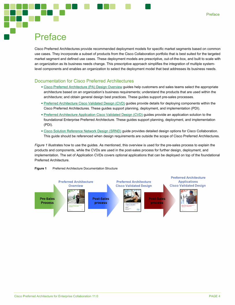
Figure 1 illustrates how to use the guides. As mentioned, this overview is used for the pre-sales process to explain the products and components, while the CVDs are used in the post-sales process for further design, deployment, and implementation. The set of Application CVDs covers optional applications that can be deployed on top of the foundational Preferred Architecture.
Figure 1 Preferred Architecture Documentation Structure
Cisco Preferred Architecture for Enterprise Collaboration 11.0 PAGE 5
Preface
About This Guide The Cisco Preferred Architecture for Enterprise Collaboration is for:
• Sales teams that design and sell collaboration solutions
• Customers and sales teams who want to understand the overall collaboration architecture, its components, and general design best practices
Readers of this guide should have a general knowledge of Cisco Voice, Video, and Collaboration products and a basic understanding of how to deploy these products.
This guide simplifies the design and sales process by:
• Recommending products in the Cisco Collaboration portfolio that are built for the enterprise and that provide appropriate feature sets for this market
• Detailing a collaboration architecture and identifying general best practices for deploying in enterprise organizations
For detailed information about configuring, deploying, and implementing this architecture, consult the related CVD documents on the Design Zone for Collaboration.
Cisco Preferred Architecture for Enterprise Collaboration 11.0 PAGE 6
Introduction
Introduction In recent years, many new collaborative tools have been introduced to the market, enabling organizations to extend collaboration outside the walls of their businesses. Providing access to collaborative tools for employees outside the office is no longer a luxury; it is mandatory for businesses to stay relevant in today’s market. Today’s users expect immediate access to these tools from a wide variety of portable and mobile devices. Many of these same tools can be extended to customers and partners, helping strengthen these relationships.
Organizations realize the added value that collaboration applications bring to their businesses through increased employee productivity and enhanced customer relationships. Not long ago, interoperability among collaboration applications was sparse, and applications were difficult to deploy and use. Since then, significant advances have been made in the collaboration space, simplifying deployment, improving interoperability, and enhancing the overall user experience. Additionally, individuals have adopted a wide variety of smart phones, social media, and collaboration applications in their personal lives.
Organizations can now feel comfortable providing collaboration applications that employees will quickly adopt and that provide maximum value. These new collaboration tools enhance an organization’s overall business processes, make its employees more productive, and open the door to new and innovative ways for communicating with business partners and customers. Today’s collaboration solutions offer organizations the ability to integrate video, audio, and web participants into a single, unified meeting experience.
Technology Use Cases Organizations want to streamline their business processes, optimize employee productivity, and enhance relationships with partners and customers. The Cisco Preferred Architecture (PA) for Enterprise Collaboration delivers capabilities that enable organizations to realize immediate gains in productivity and enhanced relationships. Additionally, the following technology use cases offer organizations opportunities to develop new, advanced business processes that deliver even more value in these areas:
• Consolidate Communications Infrastructure — Bring together voice, video, and data into a single IP network to simplify management and support effective communications.
• Incorporate Video into Meetings — Improve communications, relationships, and productivity by making it easier to meet face-to-face over distance.
• Extend Telephony with Video — Facilitate face-to-face video communications directly from end-user phones or softphone applications.
• Support Teleworkers and Branch Offices — Let employees work from multiple locations, whether satellite offices, home offices, or when traveling.
• Collaborate with External Organizations — Easily share information, interact in real time, and communicate using technologies beyond email and telephone.
• Create Flexible Work Areas and Office Spaces — Scale office space and create work areas that foster employee inclusiveness, collaboration, innovation, and teamwork.
• Deploy a Unified Communications Architecture — Provide the entire global organization with a single communications tool set for all users.
Information about Cisco Collaboration Technologies and use cases is available on Cisco.com.
Cisco Preferred Architecture for Enterprise Collaboration 11.0 PAGE 7
Introduction
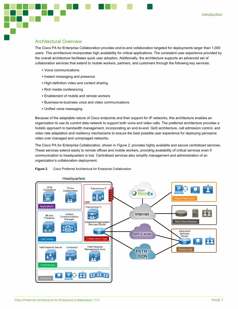
Architectural Overview The Cisco PA for Enterprise Collaboration provides end-to-end collaboration targeted for deployments larger than 1,000 users. This architecture incorporates high availability for critical applications. The consistent user experience provided by the overall architecture facilitates quick user adoption. Additionally, the architecture supports an advanced set of collaboration services that extend to mobile workers, partners, and customers through the following key services:
• Voice communications
• Instant messaging and presence
• High-definition video and content sharing
• Rich media conferencing
• Enablement of mobile and remote workers
• Business-to-business voice and video communications
• Unified voice messaging
Because of the adaptable nature of Cisco endpoints and their support for IP networks, this architecture enables an organization to use its current data network to support both voice and video calls. The preferred architecture provides a holistic approach to bandwidth management, incorporating an end-to-end QoS architecture, call admission control, and video rate adaptation and resiliency mechanisms to ensure the best possible user experience for deploying pervasive video over managed and unmanaged networks.
The Cisco PA for Enterprise Collaboration, shown in Figure 2, provides highly available and secure centralized services. These services extend easily to remote offices and mobile workers, providing availability of critical services even if communication to headquarters is lost. Centralized services also simplify management and administration of an organization’s collaboration deployment.
Figure 2 Cisco Preferred Architecture for Enterprise Collaboration
Cisco Preferred Architecture for Enterprise Collaboration 11.0 PAGE 8
Introduction
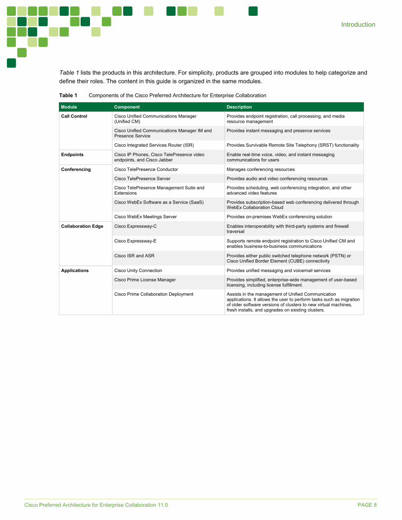
Table 1 lists the products in this architecture. For simplicity, products are grouped into modules to help categorize and define their roles. The content in this guide is organized in the same modules.
Table 1 Components of the Cisco Preferred Architecture for Enterprise Collaboration
Module Component Description Call Control Cisco Unified Communications Manager
(Unified CM) Provides endpoint registration, call processing, and media resource management
Cisco Unified Communications Manager IM and Presence Service
Provides instant messaging and presence services
Cisco Integrated Services Router (ISR) Provides Survivable Remote Site Telephony (SRST) functionality Endpoints Cisco IP Phones, Cisco TelePresence video
endpoints, and Cisco Jabber Enable real-time voice, video, and instant messaging communications for users
Conferencing Cisco TelePresence Conductor Manages conferencing resources Cisco TelePresence Server Provides audio and video conferencing resources Cisco TelePresence Management Suite and Extensions
Provides scheduling, web conferencing integration, and other advanced video features
Cisco WebEx Software as a Service (SaaS) Provides subscription-based web conferencing delivered through WebEx Collaboration Cloud
Cisco WebEx Meetings Server Provides on-premises WebEx conferencing solution Collaboration Edge Cisco Expressway-C Enables interoperability with third-party systems and firewall
traversal Cisco Expressway-E Supports remote endpoint registration to Cisco Unified CM and
enables business-to-business communications Cisco ISR and ASR Provides either public switched telephone network (PSTN) or
Cisco Unified Border Element (CUBE) connectivity Applications Cisco Unity Connection Provides unified messaging and voicemail services
Cisco Prime License Manager Provides simplified, enterprise-wide management of user-based licensing, including license fulfillment.
Cisco Prime Collaboration Deployment Assists in the management of Unified Communication applications. It allows the user to perform tasks such as migration of older software versions of clusters to new virtual machines, fresh installs, and upgrades on existing clusters.
Cisco Preferred Architecture for Enterprise Collaboration 11.0 PAGE 9
Introduction
Virtualization and Core Applications Virtualizing multiple applications and consolidating them on physical servers lowers costs, minimizes rack space, lowers power requirements, and simplifies deployment and management. Virtualization also accommodates redeploying hardware and scaling software applications as organizational needs change.
Cisco Business Edition 7000 The Cisco Business Edition (BE) 7000 serves organizations with 1,000 or more users, and it is the foundation of the Cisco PA for Enterprise Collaboration. The Cisco BE7000 is built on a Cisco Unified Computing System (UCS) that ships ready-for-use with a preinstalled virtualization hypervisor and application installation files. The Cisco BE7000 solution offers premium voice, video, messaging, instant messaging and presence, and contact center features on a single, integrated platform. For more information about the Cisco BE7000, see the data sheet.
Core Applications In the Cisco PA for Enterprise Collaboration, the following applications are deployed on multiple UCS servers to provide hardware and software redundancy:
• Cisco Unified Communications Manager
• Cisco Unified Communications Manager IM and Presence Service
• Cisco Unity Connection
• Cisco Expressway, consisting of Expressway-C and Expressway-E
• Cisco TelePresence Conductor
• Cisco TelePresence Server
• Cisco TelePresence Management Suite and Extensions
• Cisco Prime Collaboration Deployment
• Cisco Prime License Manager
We recommend always deploying redundant components and configurations to provide the highest availability for critical business applications.
High Availability The Cisco PA for Enterprise Collaboration provides high availability for all deployed applications by means of the underlying clustering mechanism present in all Cisco Unified Communications applications.
Clustering replicates the administration and configuration of deployed applications to backup instances of those applications. If an instance of an application fails, Cisco Unified Communications services – such as endpoint registration, call processing, messaging, business-to-business communication, and many others – continue to operate on the remaining instance(s) of the application. This failover process is transparent to the users. In addition to clustering, the Cisco PA for Enterprise Collaboration provides high availability through the use of redundant power supplies, network connectivity, and disk arrays.
Sizing Considerations Sizing a deployment can become complex for large enterprises with sophisticated requirements. The Preferred Architecture for Enterprise Collaboration Cisco Validated Design (CVD) Guide presents some examples that simplify the sizing process. In addition, Cisco provides several tools to assist with sizing a deployment. The sizing tools are available to Cisco certified partners at http://tools.cisco.com/cucst. If you do not have access to the sizing tools, contact your Cisco account representative or Cisco certified partner to obtain system sizing information.
Cisco Preferred Architecture for Enterprise Collaboration 11.0 PAGE 10
Introduction
Licensing Details about the individual licenses for the endpoints and infrastructure components in the Cisco Preferred Architecture for Enterprise Collaboration are beyond the scope of this document. Information about Cisco Unified Communications licensing is available on the License Administration Portal at https://tools.cisco.com/SWIFT/LicensingUI/Home. The License Administration Portal also provides instructions and tools to assist with license administration.
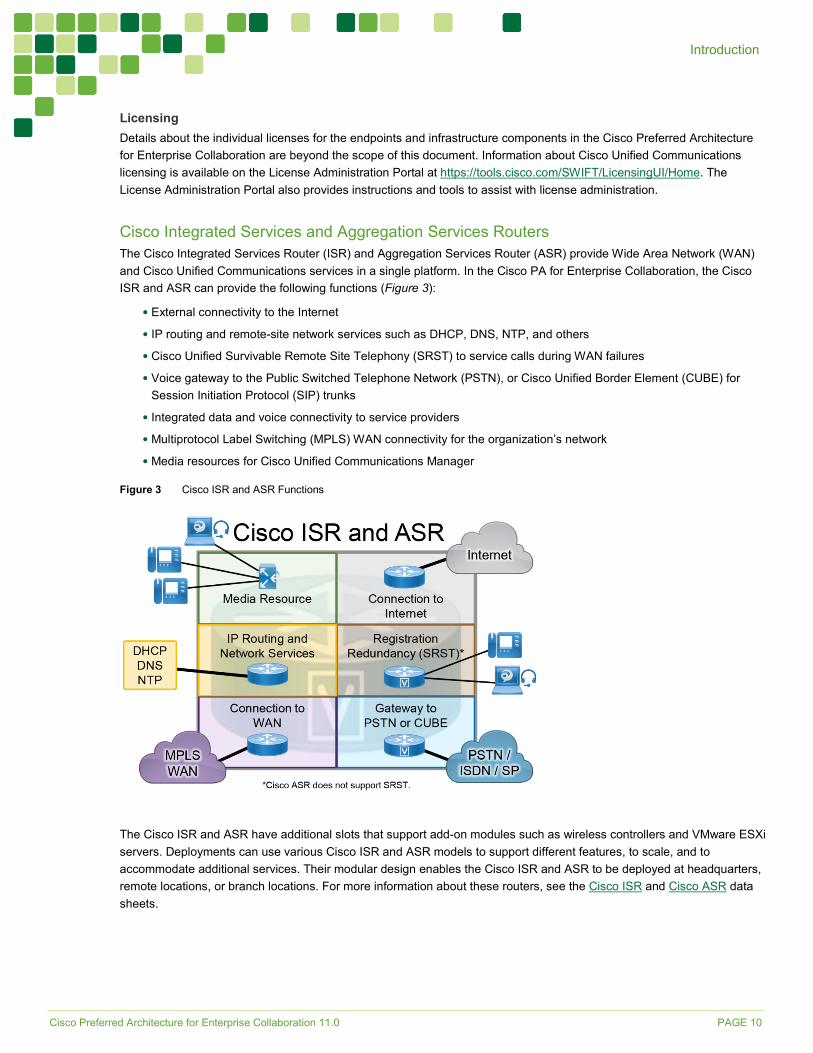
Cisco Integrated Services and Aggregation Services Routers The Cisco Integrated Services Router (ISR) and Aggregation Services Router (ASR) provide Wide Area Network (WAN) and Cisco Unified Communications services in a single platform. In the Cisco PA for Enterprise Collaboration, the Cisco ISR and ASR can provide the following functions (Figure 3):
• External connectivity to the Internet
• IP routing and remote-site network services such as DHCP, DNS, NTP, and others
• Cisco Unified Survivable Remote Site Telephony (SRST) to service calls during WAN failures
• Voice gateway to the Public Switched Telephone Network (PSTN), or Cisco Unified Border Element (CUBE) for Session Initiation Protocol (SIP) trunks
• Integrated data and voice connectivity to service providers
• Multiprotocol Label Switching (MPLS) WAN connectivity for the organization’s network
• Media resources for Cisco Unified Communications Manager
Figure 3 Cisco ISR and ASR Functions
The Cisco ISR and ASR have additional slots that support add-on modules such as wireless controllers and VMware ESXi servers. Deployments can use various Cisco ISR and ASR models to support different features, to scale, and to accommodate additional services. Their modular design enables the Cisco ISR and ASR to be deployed at headquarters, remote locations, or branch locations. For more information about these routers, see the Cisco ISR and Cisco ASR data sheets.
Cisco Preferred Architecture for Enterprise Collaboration 11.0 PAGE 11
Endpoints
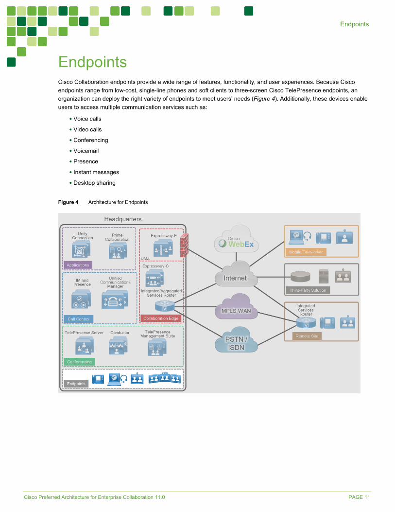
Endpoints Cisco Collaboration endpoints provide a wide range of features, functionality, and user experiences. Because Cisco endpoints range from low-cost, single-line phones and soft clients to three-screen Cisco TelePresence endpoints, an organization can deploy the right variety of endpoints to meet users’ needs (Figure 4). Additionally, these devices enable users to access multiple communication services such as:
• Voice calls
• Video calls
• Conferencing
• Voicemail
• Presence
• Instant messages
• Desktop sharing
Figure 4 Architecture for Endpoints
Cisco Preferred Architecture for Enterprise Collaboration 11.0 PAGE 12
Endpoints
Recommended Deployment Cisco Unified Communications Manager (Unified CM) is the call control server for the Cisco PA for Enterprise Collaboration. Cisco IP Phones, Jabber clients, and TelePresence video endpoints use SIP to register directly to Cisco Unified CM. The Unified CM cluster’s failover mechanism provides endpoint registration redundancy. If a WAN failure occurs and endpoints at remote locations cannot register to Unified CM, they use SRST functionality for local and PSTN calls, but some services such as voicemail and presence might not be available.
We recommend the endpoints listed in the following tables because they provide optimal features for this design. Cisco has a range of endpoints with various features and functionality that an organization can also use to address its business needs.
Table 2 Cisco IP Phones
Product Description Cisco IP Phone 7811 Public space, single-line phone Cisco IP Phone 8800 Series General office use, multiple-line phone Cisco IP Phone 8831 IP conference phone
Table 3 Cisco TelePresence and Video Endpoints
Product Description Cisco DX Series Personal TelePresence endpoint for the desktop Cisco MX Series TelePresence multipurpose room endpoint Cisco SX Series Integrator series TelePresence endpoint Cisco IX Series Immersive TelePresence room system
Table 4 Cisco Jabber
Product Description Mobile: Jabber for Android Jabber for iPhone and iPad Desktop: Jabber for Mac Jabber for Windows
Soft client with integrated voice, video, voicemail, instant messaging, and presence functionality for mobile devices and personal computers
Table 5 Comparison of Endpoint Features and Capabilities
Product(s) Audio Video Content Sharing
Unified CM High Availability
Mobile and Remote Access
Audio SRST
IP Phone 7811 Y N N Y Y Y IP Phone 8800 Series Y Y1 N Y Y Y IP Phone 8831 Y N N Y N Y DX Series Y Y Y2 Y Y Y MX Series Y Y Y Y Y N SX Series Y Y Y Y Y N IX Series Y Y Y Y N N
Jabber Mobile Y Y N Y Y Y Jabber Desktop Y Y Y Y Y Y 1. Only the IP Phones 8845 and 8865 support video. 2. The Cisco DX650 supports only receiving the content share.
Cisco Preferred Architecture for Enterprise Collaboration 11.0 PAGE 13
Call Control
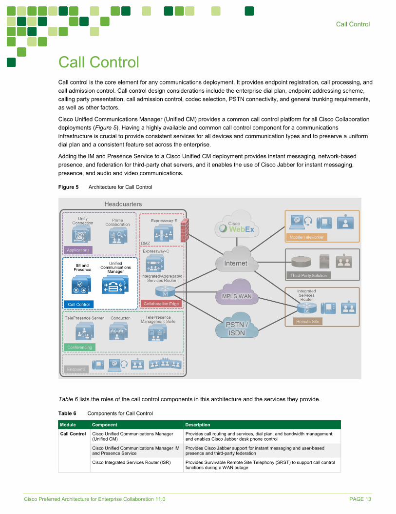
Call Control Call control is the core element for any communications deployment. It provides endpoint registration, call processing, and call admission control. Call control design considerations include the enterprise dial plan, endpoint addressing scheme, calling party presentation, call admission control, codec selection, PSTN connectivity, and general trunking requirements, as well as other factors.
Cisco Unified Communications Manager (Unified CM) provides a common call control platform for all Cisco Collaboration deployments (Figure 5). Having a highly available and common call control component for a communications infrastructure is crucial to provide consistent services for all devices and communication types and to preserve a uniform dial plan and a consistent feature set across the enterprise.
Adding the IM and Presence Service to a Cisco Unified CM deployment provides instant messaging, network-based presence, and federation for third-party chat servers, and it enables the use of Cisco Jabber for instant messaging, presence, and audio and video communications.
Figure 5 Architecture for Call Control
Table 6 lists the roles of the call control components in this architecture and the services they provide.
Table 6 Components for Call Control
Module Component Description Call Control Cisco Unified Communications Manager
(Unified CM) Provides call routing and services, dial plan, and bandwidth management; and enables Cisco Jabber desk phone control
Cisco Unified Communications Manager IM and Presence Service
Provides Cisco Jabber support for instant messaging and user-based presence and third-party federation
Cisco Integrated Services Router (ISR) Provides Survivable Remote Site Telephony (SRST) to support call control functions during a WAN outage
Cisco Preferred Architecture for Enterprise Collaboration 11.0 PAGE 14
Call Control
Recommended Deployment • Deploy a single Cisco Unified CM cluster for an enterprise with a central site and remote offices. Deploy call
processing subscribers in pairs for scalability and redundancy.
• Add additional Cisco Unified CM clusters for very large sites or for geographic and/or organizational separation. Configure SIP trunks to interconnect individual Cisco Unified CM clusters.
• Deploy a pair of IM and Presence Service servers in a cluster configuration. Add more pairs for scalability.
• Enable Cisco SRST on the Cisco ISR as a backup service at remote sites to provide high availability.
Benefits This deployment provides the following benefits:
• Call control is centralized at a single location that serves multiple remote sites.
• Common telephony features are available across voice and video endpoints.
• Single call control and a unified dial plan are provided for voice and video endpoints.
• Critical business applications are highly available and redundant.
Deployment Best Practices
Cisco Unified Communications Manager and IM and Presence Service
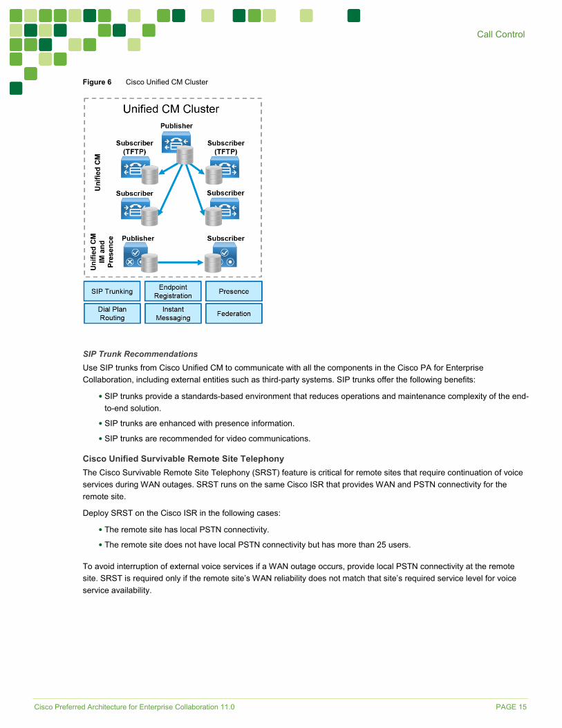
Cluster Recommendations Cisco Unified CM and IM and Presence support clustering, which is the grouping of nodes that work together as a single logical entity. The publisher node contains the cluster’s configuration database, which is replicated to the call processing subscriber nodes and TFTP nodes in the cluster.
Clustering provides an automatic redundancy mechanism for endpoints and for Cisco Unified CM services, such as the ability to receive and process incoming calls. To provide 1:1 redundancy, always deploy call processing subscribers and TFTP nodes in pairs. Each Unified CM cluster must have at least one pair of call processing subscribers and a pair of TFTP nodes in addition to the publisher node, for a minimum of five Cisco Unified CM nodes in a cluster (Figure 6). While the call processing subscribers provide endpoint registration and call processing capabilities, the pair of TFTP nodes provides configuration and firmware updates to endpoints.
All the TFTP nodes and subscriber nodes periodically receive updates of the configuration database from the dedicated publisher node. These database updates enable all the subscriber nodes to operate in a consistent configuration state.
To provide load balancing of call processing services across the subscribers and to reduce failover response times, deploy each call processing subscriber pair in an active/active redundancy scheme.
For IM and Presence, we recommend deploying a minimum of one IM and Presence publisher and one subscriber. The IM and Presence publisher is not a dedicated node, and the publisher and subscriber provide redundancy for each other. (Figure 6)
Add more pairs of IM and Presence subscribers or Unified CM call processing nodes to accommodate more users.
Cisco Preferred Architecture for Enterprise Collaboration 11.0 PAGE 15
Call Control
Figure 6 Cisco Unified CM Cluster
SIP Trunk Recommendations Use SIP trunks from Cisco Unified CM to communicate with all the components in the Cisco PA for Enterprise Collaboration, including external entities such as third-party systems. SIP trunks offer the following benefits:
• SIP trunks provide a standards-based environment that reduces operations and maintenance complexity of the end-to-end solution.
• SIP trunks are enhanced with presence information.
• SIP trunks are recommended for video communications.
Cisco Unified Survivable Remote Site Telephony The Cisco Survivable Remote Site Telephony (SRST) feature is critical for remote sites that require continuation of voice services during WAN outages. SRST runs on the same Cisco ISR that provides WAN and PSTN connectivity for the remote site.
Deploy SRST on the Cisco ISR in the following cases:
• The remote site has local PSTN connectivity.
• The remote site does not have local PSTN connectivity but has more than 25 users.
To avoid interruption of external voice services if a WAN outage occurs, provide local PSTN connectivity at the remote site. SRST is required only if the remote site’s WAN reliability does not match that site’s required service level for voice service availability.
Cisco Preferred Architecture for Enterprise Collaboration 11.0 PAGE 16
Call Control
If a WAN failure occurs at a site with SRST and local PSTN access, the following services will be available:
• Internal point-to-point voice calls
• External voice calls through the PSTN
• Call hold, transfer, and conference
• Music on hold
Note: SRST is not available for Cisco MX or SX Series endpoints. See Table 5 for information about endpoints that support SRST.
Dial Plan A structured, well-designed dial plan is essential to successful deployment of any call control system. When designing a dial plan, consider the following main factors:
• Dialing habits
• Endpoint addressing
• Routing
• Directory integration
• Classes of service
Dialing Habits Dialing habits describe what end users can dial to reach various types of destinations. Dialing habits can first be classified as numeric dialing (for example, 914085550123) or alphanumeric dialing (for example, [email protected]).
Typically, different types of destinations require support for different dialing habits. For example:
• PSTN toll call: for example, in North America, 91-<10 digits>
• PSTN international call: for example, in North America, 9011-<country code + national significant number>
• Abbreviated intra-site dialing: for example, 4XXX
• Abbreviated inter-site dialing: for example, 8-<site code>-<intra-site number>
• +-dialing from directories: “+” followed by a fully qualified global PSTN number as described in ITU recommendation E.164
• URI dialing: for example, [email protected] for intra-company and inter-company dialing. Endpoints typically allow omission of the right-hand side (host portion) of the URI and they automatically append the local host portion, so that [email protected] can also be abbreviated as bob.
Further dialing habits might have to be defined for services such as call pick-up, voicemail, and others. Also, future growth should be considered so that more users and more sites can be added as needed without redesigning the dial plan.
Some dialing habits, typically PSTN dialing habits in particular, need to follow country-specific requirements or established dialing procedures. For example, in contrast to the trunk access code 9 in the above US-based examples, 0 is used for trunk access in many other countries. The dialing habit for national calls in these cases, in addition to the potential for using 0 as the trunk access code, also needs to reflect the characteristics of the national numbering plan of the respective country.
Identifying dialing habits is most important when defining an enterprise dial plan in order to avoid overlaps between any two dialing habits. For example, a trunk access code of 9 prohibits abbreviated intra-site dialing starting with 9. Avoiding overlaps between dialing habits is crucial to avoid inter-digit timeouts, which lead to bad user experiences.
In migration scenarios, the dialing habits supported by the existing system can be used as a first estimate of the dialing habits required in the new system. On the other hand, migration to a new communications system can also serve as a reason to get rid of outdated customs and practices.
Cisco Preferred Architecture for Enterprise Collaboration 11.0 PAGE 17
Call Control
Endpoint Addressing Each endpoint registered with the enterprise call control must have a unique numeric address. Endpoint addresses in Cisco Unified CM are equivalent to the directory numbers provisioned on the lines of the endpoints. Use fully qualified PSTN numbers (E.164 numbers) with a leading “+” as endpoint addresses. This format is typically referred to as +E.164 format. The benefits of using +E.164 endpoint addresses include:
• Wide use in voice networks
• No need to develop and maintain an enterprise numbering scheme
• Easy creation of correct caller ID presentation for all on-cluster and off-cluster call flows
• Easy implementation of directory lookups
• Simplified alternate routing to the PSTN in cases of WAN failure or bandwidth constraints
For endpoints without assigned PSTN-based direct inward dial (DID) numbers (no E.164 number representation exists), create enterprise-wide unique endpoint addresses outside of the default +E.164 domain. These endpoint addresses should be in line with the internal dialing habit defined to reach these endpoints. If, for example, the abbreviated inter-site dialing habit to reach a set of non-DID endpoints in a given site is 84915XXX, then these non-DID endpoints should use this numbering scheme for their endpoint addresses.
In addition to the primary numeric endpoint addresses, administrators can provision alphanumeric URIs (for example, [email protected]) in Cisco Unified CM to serve as aliases for the primary addresses, and users can enter the URI as an alternate way to dial the destination endpoint.
Routing The routing portion of the dial plan enables users to reach the correct destinations when they use the defined dialing habits.
The primary numeric routing is based on +E.164 numbers. External routes to other transport networks such as the PSTN also use the +E.164 scheme. Endpoint addresses in +E.164 provide +E.164 on-net dialing without any further configuration. All other numeric dialing habits, such as abbreviated inter-site and intra-site dialing, are implemented as overlays by adding the appropriate translation patterns to the dial plan to map from the implemented dialing habit to the +E.164 global routing address format. This allows users to reach the same endpoint by means of different dialing habits, depending on user preference.
Alpha-numeric URIs, as aliases for numeric addresses, provide an alternative means of reaching endpoints. The benefits of URI dialing and routing include:
• Conformity with the native dialing habit on most video systems
• Easier business-to-business connectivity
• Direct mapping from instant messaging identifiers to addresses (easier escalation of business-to-business IM sessions to voice and/or video), although technically IM identifiers and SIP URIs are not necessarily identical
If an endpoint is enabled for business-to-business calls over the Internet, we recommend associating a SIP URI to the device so that the business-to-business routing logic can be based on SIP URIs.
As with numeric routing, if an alias or SIP URI is recognized as an internal destination and is associated with a specific device, then Cisco Unified CM sends the call to that device. However, if the dialed SIP URI does not match any registered endpoint alias, Cisco Unified CM uses SIP route patterns to determine where to send the call. For example, if the dialed alias [email protected] does not exist internally, Cisco Unified CM uses a SIP route pattern (such as *.com) to send the call to Expressway-C as a business-to-business call.
Cisco Preferred Architecture for Enterprise Collaboration 11.0 PAGE 18
Call Control
Directory Integration To enable users to search contacts and dial from the directory, integrate Cisco Unified CM with the organization’s LDAP directory. Although Cisco Unified CM allows the creation of local user contacts, LDAP directory integration is required when using Cisco Jabber because it provides a single location for directory management and enables users to authenticate to Cisco Unified CM and Cisco Jabber by using their LDAP directory credentials.
Cisco Unified CM pulls user and contact information from LDAP directories and synchronizes user parameters – name, surname, username, telephone number, and SIP URI – when changes occur. For example, use the telephoneNumber attribute to populate the Telephone Number field in the Cisco Unified CM directory. The format of phone numbers in the corporate directory must be globally significant and must match one of the defined dialing habits. Corporate directories typically should have all phone numbers in +E.164 format (leading “+” followed by the fully qualified global number) as long as a DID exists. Only this format allows the phone number in the corporate directory to be used universally inside and outside the enterprise. Non-DID numbers that are not in +E.164 format could be used to dial uses internally from the directory, but they would have no significance outside the enterprise. Use the mail attribute to populate the Directory URI field in the Cisco Unified CM directory if URI dialing is used.
The IM and Presence Service pulls user and contact information from Cisco Unified CM.
Class of Service Classes of service define which users can access which services, such as allowing only emergency and local calls from lobby phones while allowing unrestricted calls from executive phones. The complexity of the dial plan is directly related to the number of differentiated classes of service it supports.
To define classes of service, configure partitions and calling search spaces in Cisco Unified CM. The number of classes of services supported by a dial plan depends on the granularity and complexity of the classes. For more information about classes of service and details on enterprise dial plan design, see the Cisco Collaboration SRND.
Multi-Cluster Deployment Considerations Consider deploying more than one Cisco Unified CM cluster if you have any of the following requirements:
• Administrational separation
This includes the need to keep users from different parts of the organization on separate infrastructures, or the requirement to have different departments operate different parts of the communications infrastructure.
• Geographic footprint
Technical limitations such as excessive propagation delay might prohibit endpoint registrations (for example, endpoints in Asia registering to an enterprise call control hosted in the US).
In a multi-cluster deployment, interconnect all the individual Unified CM clusters through SIP trunks. To avoid session traversal through individual clusters, deploy a full mesh of SIP trunks. With four or more clusters, deploy Cisco Unified CM Session Management Edition to centralize the dial plan and trunking and to avoid the complexity of a full-mesh SIP trunk topology.
In multi-cluster deployments, use Global Dial Plan Replication (GDPR) to replicate dial plan information between clusters. GDPR can advertise a +E.164 number, one enterprise significant number (ESN), and up to five alpha-numeric URIs per directory number. An ESN is the abbreviated inter-site dialing equivalent of a directory number. The information advertised and learned through GDPR enables deterministic intercluster routing for these dialing habits:
• +E.164 dialing based on the advertised +E.164 numbers
• Enterprise abbreviated inter-site dialing based on the advertised ESNs
• Alpha-numeric URI dialing based on the advertised URIs
Cisco Preferred Architecture for Enterprise Collaboration 11.0 PAGE 19
Conferencing
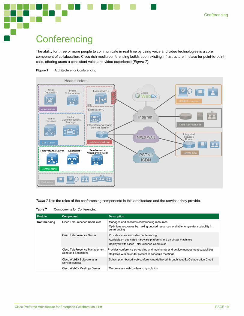
Conferencing The ability for three or more people to communicate in real time by using voice and video technologies is a core component of collaboration. Cisco rich media conferencing builds upon existing infrastructure in place for point-to-point calls, offering users a consistent voice and video experience (Figure 7).
Figure 7 Architecture for Conferencing
Table 7 lists the roles of the conferencing components in this architecture and the services they provide.
Table 7 Components for Conferencing
Module Component Description Conferencing Cisco TelePresence Conductor Manages and allocates conferencing resources
Optimizes resources by making unused resources available for greater scalability in conferencing
Cisco TelePresence Server Provides voice and video conferencing Available on dedicated hardware platforms and on virtual machines Deployed with Cisco TelePresence Conductor
Cisco TelePresence Management Suite and Extensions
Provides conference scheduling and monitoring, and device management capabilities Integrates with calendar system to schedule meetings
Cisco WebEx Software as a Service (SaaS)
Subscription-based web conferencing delivered through WebEx Collaboration Cloud
Cisco WebEx Meetings Server On-premises web conferencing solution
Cisco Preferred Architecture for Enterprise Collaboration 11.0 PAGE 20
Conferencing
There are three types of conferences:
• Instant or ad hoc — A conference that is not scheduled or organized in advance. For example, a call between two parties who add other parties to the call is an instant conference.
• Permanent or rendezvous — A conference that requires callers to dial a predetermined number or URI to reach a shared conferencing resource. Meet-me, static, and rendezvous are other names for this type of conference.
• Scheduled — A conference planned in advance with a predetermined start time. Typically, conference resources are guaranteed to be available upon the start of the scheduled conference.
Recommended Deployment
Audio and Video Conferencing • Deploy Cisco TelePresence Servers in remotely managed mode for all conference types.
◦ Deploy Cisco TelePresence Conductors in a cluster with TelePresence Servers as managed conference bridges.
◦ Integrate the TelePresence Conductor cluster with Cisco Unified CM through SIP trunks and registered media resource conference bridges for instant conferences.
◦ Integrate the TelePresence Conductor cluster with Unified CM through SIP trunks and route patterns for permanent and scheduled conferences.
◦ Deploy Cisco TelePresence Management Suite (TMS) to schedule conferences with TelePresence Conductors. Deploy Cisco TelePresence Management Suite Provisioning Extension (TMSPE) for provisioning of personal collaboration meeting rooms (CMRs). Deploy Cisco TelePresence Management Suite Extension for Microsoft Exchange (TMSXE) to allow end users to schedule meetings using Microsoft Outlook clients.
• Deploy Cisco WebEx Software as a Service (SaaS) for scheduled web conferences. If customers have special requirements that forbid storage of any data outside the company, Cisco WebEx Meetings Server can be deployed on-premises for scheduled web conferences.
• Integrate Cisco WebEx conferencing with on-premises voice and video conferencing through the CMR Hybrid solution.
Benefits This deployment provides the following benefits:
• Users have a consistent experience for launching and joining various types of conferences.
• A single conferencing platform provides on-premises audio and video conferencing.
• CMR Hybrid allows users to connect to meetings either from their video and audio devices or through the WebEx cloud with a meeting client running on their desktop or mobile devices.
• It provides users with real-time, high-definition video conferencing, including the ability to share content easily over a dedicated presentation channel.
• Cisco TMS provides users with enhanced features such as directories and One Button To Push (OBTP) on controlled endpoints. It enables administrators to import user profiles from Microsoft Active Directory that allow access control to various components and configured systems.
Cisco Preferred Architecture for Enterprise Collaboration 11.0 PAGE 21
Conferencing
Deployment Best Practices
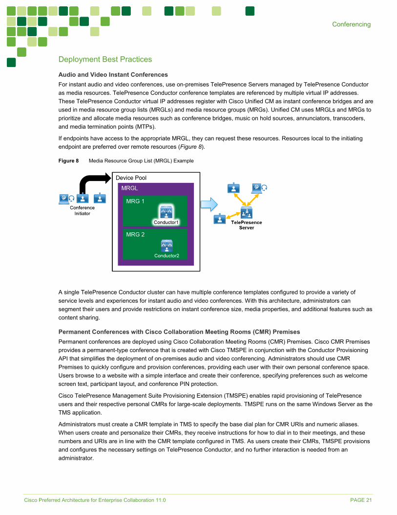
Audio and Video Instant Conferences For instant audio and video conferences, use on-premises TelePresence Servers managed by TelePresence Conductor as media resources. TelePresence Conductor conference templates are referenced by multiple virtual IP addresses. These TelePresence Conductor virtual IP addresses register with Cisco Unified CM as instant conference bridges and are used in media resource group lists (MRGLs) and media resource groups (MRGs). Unified CM uses MRGLs and MRGs to prioritize and allocate media resources such as conference bridges, music on hold sources, annunciators, transcoders, and media termination points (MTPs).
If endpoints have access to the appropriate MRGL, they can request these resources. Resources local to the initiating endpoint are preferred over remote resources (Figure 8).
Figure 8 Media Resource Group List (MRGL) Example
A single TelePresence Conductor cluster can have multiple conference templates configured to provide a variety of service levels and experiences for instant audio and video conferences. With this architecture, administrators can segment their users and provide restrictions on instant conference size, media properties, and additional features such as content sharing.
Permanent Conferences with Cisco Collaboration Meeting Rooms (CMR) Premises Permanent conferences are deployed using Cisco Collaboration Meeting Rooms (CMR) Premises. Cisco CMR Premises provides a permanent-type conference that is created with Cisco TMSPE in conjunction with the Conductor Provisioning API that simplifies the deployment of on-premises audio and video conferencing. Administrators should use CMR Premises to quickly configure and provision conferences, providing each user with their own personal conference space. Users browse to a website with a simple interface and create their conference, specifying preferences such as welcome screen text, participant layout, and conference PIN protection.
Cisco TelePresence Management Suite Provisioning Extension (TMSPE) enables rapid provisioning of TelePresence users and their respective personal CMRs for large-scale deployments. TMSPE runs on the same Windows Server as the TMS application.
Administrators must create a CMR template in TMS to specify the base dial plan for CMR URIs and numeric aliases. When users create and personalize their CMRs, they receive instructions for how to dial in to their meetings, and these numbers and URIs are in line with the CMR template configured in TMS. As users create their CMRs, TMSPE provisions and configures the necessary settings on TelePresence Conductor, and no further interaction is needed from an administrator.
Cisco Preferred Architecture for Enterprise Collaboration 11.0 PAGE 22
Conferencing
Scheduled Audio Conferences Customers with audio-only phones can use Cisco WebEx Software as a Service (SaaS) or Cisco WebEx Meetings Server to host conferences. These solutions provide voice and video conferencing with content sharing capability on a single platform. Participants join the conferences using the meeting client running on their desktop or mobile device.
Cisco WebEx Software as a Service Cisco WebEx SaaS is a subscription-based service delivered through the WebEx Collaboration Cloud, where all the meetings are hosted. Few components are deployed on-premises, so this option is well suited for customers who manage their communications budget as an operational expenditure.
WebEx Collaboration Cloud is highly available and has redundancy built into the infrastructure to handle component failure. Deploy Cisco WebEx SaaS using WebEx audio for web conferencing. We highly recommend enabling HD video for the optimal video experience and enabling SSO to allow integration with the organization’s LDAP directory for access using common credentials.
For additional information on Cisco WebEx Software as a Service, see the product documentation.
Cisco WebEx Meetings Server Cisco WebEx Meetings Server is a secure, fully virtualized WebEx conferencing solution with all of its equipment deployed on-premises behind the firewall. This option works well for customers that have strict requirements forbidding storage of any data outside the company.
Cisco WebEx Meetings Server builds on top of the Cisco Collaboration infrastructure and extends the implementation of Cisco Unified CM to include conferencing. Connect Cisco WebEx Meetings Server and Cisco Unified CM by means of SIP trunks to provide services for attendees dialing into the system and for system callback to attendees to join the meetings.
Deploy Cisco WebEx Meetings Server with redundancy to provide system availability in the event of component failures. With high availability, the system uses the N+1 redundancy scheme and runs in active/active mode. In addition, we recommend enabling high-quality (HQ) video for the optimal video experience and integrating WebEx Meeting Server with the organization’s LDAP directory so that users can use the same credentials to access the meeting scheduler.
For additional information on Cisco WebEx Meetings Server, see the product documentation.
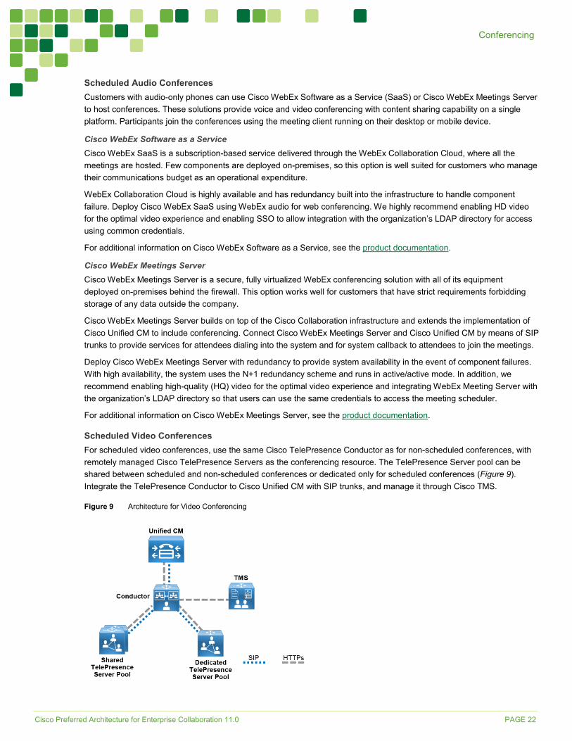
Scheduled Video Conferences For scheduled video conferences, use the same Cisco TelePresence Conductor as for non-scheduled conferences, with remotely managed Cisco TelePresence Servers as the conferencing resource. The TelePresence Server pool can be shared between scheduled and non-scheduled conferences or dedicated only for scheduled conferences (Figure 9). Integrate the TelePresence Conductor to Cisco Unified CM with SIP trunks, and manage it through Cisco TMS.
Figure 9 Architecture for Video Conferencing
Cisco Preferred Architecture for Enterprise Collaboration 11.0 PAGE 23
Conferencing
Cisco TelePresence Management Suite (TMS) runs on a Microsoft Windows server and utilizes the Microsoft SQL database to store information about users, controlled devices, and scheduled conferences. User profiles are imported from Microsoft Active Directory, and the permissions model allows for access control to various components and configured systems. Deploy Cisco TMS with Cisco TMSPE and Cisco TMSXE to provide personal collaboration meeting rooms and Microsoft Exchange integration.
A single deployment of TMS is required for each organization. Leverage the integrated system navigator folder structure to organize all endpoints and infrastructure devices. Even multinational and global organizations can benefit from a single deployment of TMS to facilitate video connections.
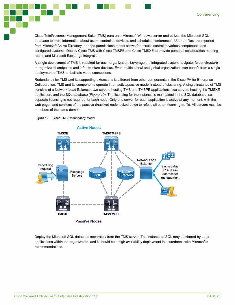
Redundancy for TMS and its supporting extensions is different from other components in the Cisco PA for Enterprise Collaboration. TMS and its components operate in an active/passive model instead of clustering. A single instance of TMS consists of a Network Load Balancer, two servers hosting TMS and TMSPE applications, two servers hosting the TMSXE application, and the SQL database (Figure 10). The licensing for the instance is maintained in the SQL database, so separate licensing is not required for each node. Only one server for each application is active at any moment, with the web pages and services of the passive (inactive) node locked down to refuse all other incoming traffic. All servers must be members of the same domain.
Figure 10 Cisco TMS Redundancy Model
Deploy the Microsoft SQL database separately from the TMS server. The instance of SQL may be shared by other applications within the organization, and it should be a high-availability deployment in accordance with Microsoft’s recommendations.
Cisco Preferred Architecture for Enterprise Collaboration 11.0 PAGE 24
Conferencing
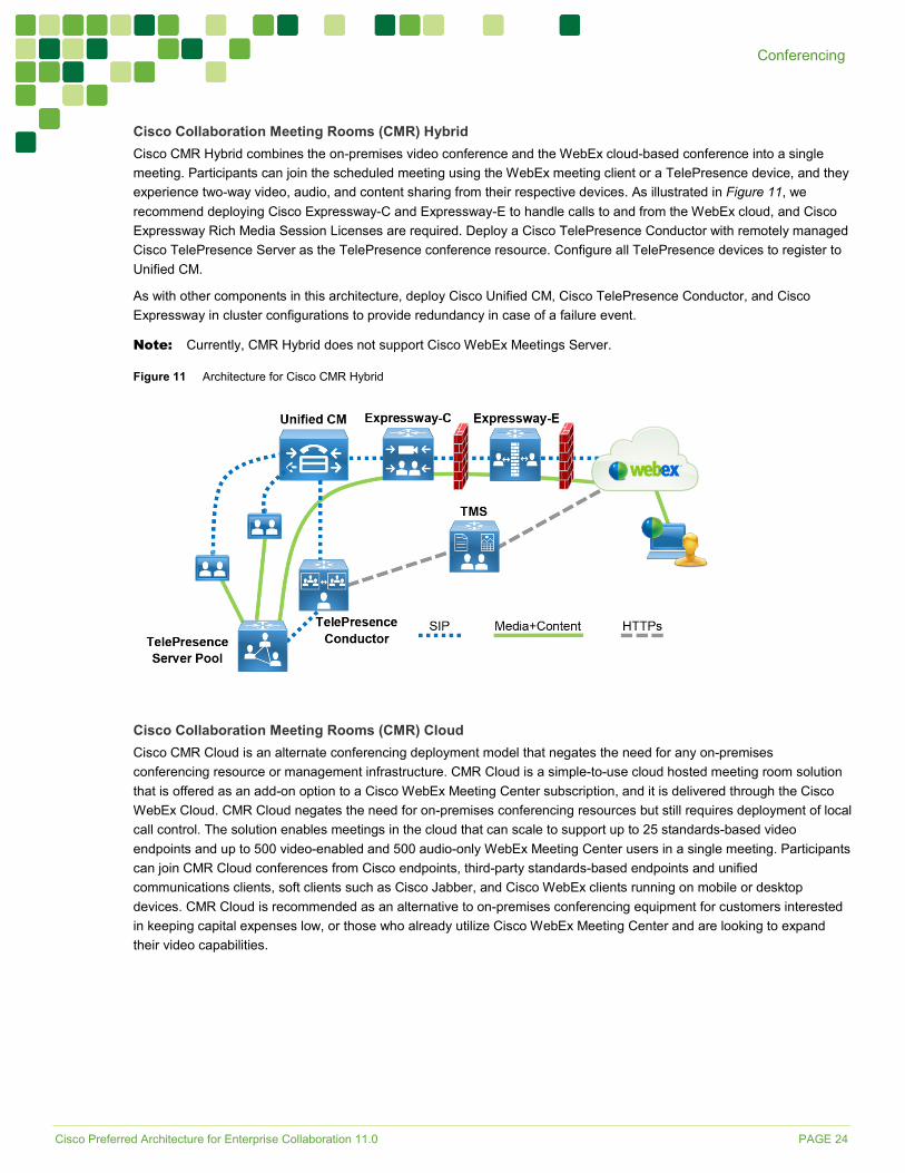
Cisco Collaboration Meeting Rooms (CMR) Hybrid Cisco CMR Hybrid combines the on-premises video conference and the WebEx cloud-based conference into a single meeting. Participants can join the scheduled meeting using the WebEx meeting client or a TelePresence device, and they experience two-way video, audio, and content sharing from their respective devices. As illustrated in Figure 11, we recommend deploying Cisco Expressway-C and Expressway-E to handle calls to and from the WebEx cloud, and Cisco Expressway Rich Media Session Licenses are required. Deploy a Cisco TelePresence Conductor with remotely managed Cisco TelePresence Server as the TelePresence conference resource. Configure all TelePresence devices to register to Unified CM.
As with other components in this architecture, deploy Cisco Unified CM, Cisco TelePresence Conductor, and Cisco Expressway in cluster configurations to provide redundancy in case of a failure event.
Note: Currently, CMR Hybrid does not support Cisco WebEx Meetings Server.
Figure 11 Architecture for Cisco CMR Hybrid
Cisco Collaboration Meeting Rooms (CMR) Cloud Cisco CMR Cloud is an alternate conferencing deployment model that negates the need for any on-premises conferencing resource or management infrastructure. CMR Cloud is a simple-to-use cloud hosted meeting room solution that is offered as an add-on option to a Cisco WebEx Meeting Center subscription, and it is delivered through the Cisco WebEx Cloud. CMR Cloud negates the need for on-premises conferencing resources but still requires deployment of local call control. The solution enables meetings in the cloud that can scale to support up to 25 standards-based video endpoints and up to 500 video-enabled and 500 audio-only WebEx Meeting Center users in a single meeting. Participants can join CMR Cloud conferences from Cisco endpoints, third-party standards-based endpoints and unified communications clients, soft clients such as Cisco Jabber, and Cisco WebEx clients running on mobile or desktop devices. CMR Cloud is recommended as an alternative to on-premises conferencing equipment for customers interested in keeping capital expenses low, or those who already utilize Cisco WebEx Meeting Center and are looking to expand their video capabilities.
Cisco Preferred Architecture for Enterprise Collaboration 11.0 PAGE 25
Conferencing
Support for Multiple Call Processing Sites Organizations may choose to implement more than one Cisco TelePresence Conductor cluster for any of the following reasons:
• Administrational separation — This includes the need to keep users from different parts of the organization on separate infrastructures or to have different departments operate different parts of the communications infrastructure.
• Geographic footprint — Physical limitations such as excessive latency between endpoints and conferencing resources could degrade the user experience (for example, US users might not have a productive collaborative meeting if they use conferencing resources located in Europe).
• Multiple Unified CM clusters — If more than one Unified CM cluster is already deployed due to the previous reasons, we recommend also deploying multiple TelePresence Conductor clusters.
Deploy multiple TelePresence Conductor clusters along with local TelePresence Server resources (Figure 12). Implement a global dial plan, as discussed in the Call Control section, to enable users to access conferences regardless of where the TelePresence Conductor or TelePresence Server is located.
Figure 12 Multiple Call Processing Sites with Conferencing
Cisco Preferred Architecture for Enterprise Collaboration 11.0 PAGE 26
Collaboration Edge
Collaboration Edge Business demand for connectivity between organizations by leveraging the Internet has increased significantly over the past few years. For many organizations, this connectivity is a fundamental requirement for conducting day-to-day activities. Moreover, securely connecting mobile workers and remote sites to each other and to headquarters is critical functionality that enables organizations to accomplish their business goals. The Cisco PA for Enterprise Collaboration addresses these needs with the Collaboration Edge architecture shown in Figure 13.
Figure 13 Architecture for Collaboration Edge
Table 8 lists the roles of the Collaboration Edge components in this architecture and the services they provide.
Table 8 Components for Collaboration Edge
Module Component Description Collaboration Edge Cisco Expressway-E The traversal server that enables secure VPN-less mobile and remote access for
TelePresence endpoints and Jabber clients. The traversal server resides in the DMZ. The solution also provides business-to-business calling, protocol interworking, and cloud connectivity.
Cisco Expressway-C The traversal client that creates a secure, trusted connection through the firewall to Expressway-E. The traversal client resides inside the enterprise network. The solution provides mobile and remote access, business-to-business calling, protocol interworking, and cloud connectivity.
Cisco Integrated Services Router (ISR) or Aggregation Services Router (ASR) with PSTN interfaces
Enables local PSTN connectivity
Cisco ISR or ASR with Cisco Unified Border Element (CUBE) software
Enables connectivity from an organization’s network to the service provider network for SIP trunks via CUBE
Cisco TelePresence ISDN Gateway
Enables local PSTN connectivity up to 720p@30fps
Cisco Preferred Architecture for Enterprise Collaboration 11.0 PAGE 27
Collaboration Edge
Recommended Deployment
Headquarters • Deploy a Cisco Expressway-C and Expressway-E server pair to enable remote Jabber and TelePresence video
endpoint registrations, and IM and Presence. Deploy a separate Expressway-C and Expressway-E server pair for secure business-to-business connectivity through the firewall. Cluster both Expressway-C and Expressway-E servers in both pairs.
• Deploy Cisco ISR or ASR as the PSTN gateway, or enable CUBE functionality on the Cisco ISR or ASR for voice connectivity from the organization’s network to the service provider network through a SIP trunk.
• Deploy video gateways if ISDN interoperability is needed.
• If full redundancy is not required, a single server pair (Expressway-C and Expressway-E) may be deployed.
Remote Sites • Deploy Cisco ISR as the PSTN gateway.
• Deploy Expressway-C and Expressway-E if the remote site has local Internet connectivity and an Internet business-to-business architecture for video calls is required.
Teleworker Sites • For video-enabled sites, deploy Cisco TelePresence endpoints utilizing the Expressway-C and Expressway-E
infrastructure at headquarters or another site.
• In addition, the Cisco Jabber client can be used without the VPN, regardless of the location of the endpoint (internal or external to the organization).
• Legacy audio and video-enabled phones can be deployed with VPN technologies. Depending on the phone type, some of them have an embedded VPN client and may be deployed without a VPN hardware client. For more information on each phone model, refer to the product documentation.
Benefits This deployment provides the following benefits:
• The Cisco ISR supports standards-based interfaces and various PSTN types, so it can be deployed globally.
• Instead of traditional PSTN interfaces, CUBE functionality can be enabled on the Cisco ISR and ASR if a SIP trunk is used.
• The Cisco ISR and ASR can be used for WAN connectivity.
• Cisco Expressway provides calling, presence, instant messaging, voicemail, and corporate directory services for Cisco Jabber and TelePresence video endpoints.
• Cisco Expressway enables video communications between organizations, partners, and vendors over the Internet.
Deployment Best Practices
Cisco Expressway Cisco Expressway provides secure firewall and NAT traversal for mobile Cisco Jabber and TelePresence video endpoints (Figure 14) and secure business-to-business communications (Figure 15). Cisco Expressway consists of two applications: Expressway-C and Expressway-E.
Deploy Cisco Expressway-C inside the network, and deploy Expressway-E in the demilitarized zone (DMZ) by connecting separate network ports on Expressway-E to the organization’s network and to the DMZ.
Cisco fully supports a virtualized Expressway-E in the DMZ; however, a dedicated server can be deployed based on the company’s security requirements.
Cisco Preferred Architecture for Enterprise Collaboration 11.0 PAGE 28
Collaboration Edge
Figure 14 Traversal for Registrations Through Firewall with Expressway-C and Expressway-E
Figure 15 Traversal for Business-to-Business Calls Through Firewall with Expressway-C and Expressway-E
Cisco Expressway-C Place Expressway-C in the trusted network inside the organization.
Deploy Expressway-C to:
• Function as a traversal client and establish a secure connection to Expressway-E through the firewall
• Establish secure or non-secure connection to Cisco Unified CM
• Integrate with an existing internal video network that uses H.323
• Enable business-to-business calls to external entities that communicate using SIP or H.323
• Provide interworking between H.323 and SIP protocols for H.323 business-to-business communications
• Enable mobile and remote access capabilities and call signaling for Cisco supported endpoints, directing them to Cisco Unified CM for SIP registration and/or the IM and Presence Service (See the Endpoints section for information on which endpoints support mobile and remote access.)
Cisco Preferred Architecture for Enterprise Collaboration 11.0 PAGE 29
Collaboration Edge
Cisco Expressway-E Because Expressway-E is reachable directly from the untrusted external network, it should be placed in a DMZ for security. The organization’s firewall policies control communications to and from this server.
Deploy Expressway-E to:
• Function as a traversal server and allow secure communications to and from Expressway-C
• Enable audio, video, and IM and Presence connections to other organizations using SIP or H.323 on the Internet
• Provide secure communications to cloud-based services, such as CMR Hybrid services, to the WebEx cloud
• Provide DNS SRV lookup service to resolve outbound calls and to receive inbound calls over the Internet
• Process registration and IM and presence information from Cisco endpoints on the external network and use secure traversal communications to pass the information to Expressway-C
• Provide interworking between protocols (between SIP and H.323, and between IPv4 and IPv6) for business-to-business communications
Connectivity for Audio and Video over the Internet URI dialing is the best practice for audio and video dialing over the Internet. We recommend assigning alphanumeric URIs to all devices that will send or receive calls over the Internet. Any device on Cisco Unified CM can be reached over the Internet by dialing the assigned alphanumeric SIP URI or the required directory number (DN) by dialing <+E.164 number>@domain. For example, a Jabber user might have a SIP URI set to [email protected] and a phone number set to +14085551234. If someone dials [email protected] or [email protected] from an external location on the Internet, Alice would receive the call on the Jabber client and all devices that share the same number.
Users on Cisco Unified CM have to dial the full SIP URI to reach a user or device from a different organization over the Internet.
The architecture for business-to-business Internet connectivity includes a client/server solution: Expressway-C and Expressway-E. Both servers can be deployed in standalone mode or in a cluster. Deploy the same number of cluster peers for Expressway-C clusters as for Expressway-E clusters.
Cisco recommends deploying dedicated Expressway-C and Expressway-E clusters per customer-chosen Internet breakout to minimize having outbound business-to-business calls traverse the WAN by routing them, instead, to an Internet breakout close to the client that initiated the call. This minimizes the business-to-business call-related utilization of the enterprise WAN.
Considerations for Outbound Business-to-Business Calls • When multiple Expressway-C and Expressway-E pairs are deployed, Unified CM can redirect an outbound call to
the edge server that is nearest to the calling endpoint, thus minimizing WAN traffic.
• For call routing over the Internet, use public DNS service records. DNS SRV records map a domain to an edge system servicing that domain for that protocol. For example, if a remote user dials [email protected], then the remote system uses DNS to query for the host offering the SIP service for the domain ent-pa.com.
• If the remote endpoint supports IP dialing only, Cisco Unified CM users can dial the IP address of the endpoint followed by a string, which will be used to route the call. As an example, the user can dial 10.10.10.10@ip instead of dialing 10.10.10.10. The string “@ip” will be used by Cisco Unified CM to route the call to the Expressway-C. Expressway will send it to the Expressway-E, which will place the call to the IP address specified.
Cisco Preferred Architecture for Enterprise Collaboration 11.0 PAGE 30
Collaboration Edge
Considerations for Inbound Calls Once a call reaches an Expressway-E, it is routed to the relevant Unified CM cluster through its corresponding Expressway-C. In deployments with multiple edges (multiple pairs of Expressway-C and Expressway-E), there are two methods to route inbound calls:
• Call routing based on the calling location
In this scenario, a business-to-business call enters the corporate network through the edge that is nearest to the calling endpoint or user. Because the call enters the corporate network after traversing a minimal distance over the Internet, this approach focuses on using the shortest path to the point of entry as the means of providing the best quality experience. In this scenario, use Geo-DNS. Geo-DNS provides unique DNS responses by geographic regions based on the source IP address of the DNS query, and it is thus able to direct an SRV query to the specific edge servicing a particular region. In this way, the calling endpoint is typically directed to the edge nearest to its calling location.
• Call routing based on the called location
It is possible to direct the inbound call to the edge that is nearest to the called endpoint. This approach has the benefit of reducing the video bandwidth consumed over the WAN, but it requires a more complex architecture that has some scaling constraints. For this reason, we do not recommend implementing this architecture when more than two edges are deployed.
Note: Call routing based on the called location applies to room and personal systems or clients that are not moving across sites.
In addition, the Cisco Collaboration Architecture enables IP-based dialing for those endpoints on the Internet that are capable to dial IP addresses only. The Expressway-E external interface IP address can be dialed from the Internet, and the call can be sent to a multipoint device or to a Cisco Unity Connection system, which will prompt the calling user to specify the destination. Once the destination is entered, the call will be sent to the specified destination.
Mobile and Remote Access The mobile and remote access feature enables Jabber clients and hardware endpoints (as indicated in Table 5, Mobile and Remote Access column) to register securely to Cisco Unified CM through Expressway-E and Expressway-C without any VPN. A Jabber client can send and receive several types of collaboration flows (audio, video, instant messaging, and presence), while a hardware endpoint can send audio and video streams. When multiple edges are deployed, we recommend using Geo-DNS services to provide the best network option based on assigning the closest edge in the DNS response.
The mobile and remote access functionality also leverages Expressway-C and Expressway-E. Both business-to-business and mobile and remote access services are supported on the same server, but we recommend deploying these services on different Expressway-C and Expressway-E pairs in order to scale.
Instant Messaging and Presence Federation Instant messaging and presence federation involves allowing users to send XMPP traffic through an organization’s external firewall for chat and presence status information to and from users in another organization.
Prior Cisco architectures involved using the Cisco ASA firewall as a TLS proxy and allowing inbound ports to be opened through the external firewall to directly access the IM and Presence servers internally.
Expressway-C and Expressway-E are now the preferred architecture for external IM and Presence federation.
This architecture is still valid for SIP federation for IM and Presence only, while Expressway-C and Expressway-E provide XMPP federation with voice and video escalation.
Cisco Preferred Architecture for Enterprise Collaboration 11.0 PAGE 31
Collaboration Edge
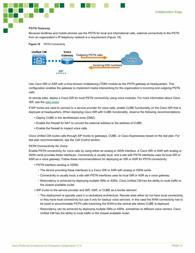
PSTN Gateway Because landlines and mobile phones use the PSTN for local and international calls, external connectivity to the PSTN from an organization’s IP telephony network is a requirement (Figure 16).
Figure 16 PSTN Connectivity
Use Cisco ISR or ASR with a time-division multiplexing (TDM) module as the PSTN gateway at headquarters. This configuration enables the gateway to implement media interworking for the organization’s incoming and outgoing PSTN calls.
At remote sites, deploy a Cisco ISR for local PSTN connectivity using voice modules. For more information about Cisco ISR, see the data sheet.
If SIP trunks are used to connect to a service provider for voice calls, enable CUBE functionality on the Cisco ISR that is deployed at headquarters. When deploying Cisco ISR with CUBE functionality, observe the following recommendations:
• Deploy CUBE in the demilitarized zone (DMZ).
• Enable the firewall for NAT to convert the external address to the address of CUBE.
• Enable the firewall to inspect voice calls.
Cisco Unified CM routes calls through SIP trunks to gateways, CUBE, or Cisco Expressway based on the dial plan. For dial plan recommendations, see the Call Control section.
PSTN Connectivity for Voice Enable PSTN connectivity for voice calls by using either an analog or ISDN interface. A Cisco ISR or ASR with analog or ISDN cards provides these interfaces. Connectivity is usually local, and a site with PSTN interfaces uses its local ISR or ASR as a voice gateway. Follow these recommendations for deploying an ISR or ASR for PSTN connectivity:
• PSTN interface (analog or ISDN)
◦ The device providing these interfaces is a Cisco ISR or ASR with analog or ISDN cards.
◦ Connectivity is usually local; a site with PSTN interfaces uses its local ISR or ASR as a voice gateway.
◦ Redundancy is achieved by deploying multiple ISRs or ASRs. Cisco Unified CM has the ability to route traffic to the closest available router.
• SIP trunks to the service provider and ISR, ASR, or CUBE as a border element
◦ This deployment is typically used in a centralized architecture. Remote sites either do not have local connectivity, or they have local connectivity but use it only for backup voice services. In this case the WAN connectivity has to be sized to accommodate PSTN calls traversing the WAN to the central site where CUBE is deployed.
◦ Redundancy can be achieved by deploying multiple ISRs or ASRs, sometimes to different voice carriers. Cisco Unified CM has the ability to route traffic to the closest available router.

Cisco Preferred Architecture for Enterprise Collaboration 11.0 PAGE 32
Collaboration Edge
ISDN Connectivity for Video Although many organizations now use the Internet for business-to-business video connectivity, legacy interoperability with ISDN networks might still be required if the called party is not reachable through the Internet. To provide ISDN connectivity for video, use the following Cisco TelePresence ISDN gateways:
• Standalone unit – Cisco TelePresence ISDN GW 3241
• Chassis mounted unit – Cisco TelePresence ISDN GW MSE 8321
Cisco Preferred Architecture for Enterprise Collaboration 11.0 PAGE 33
Applications
Applications While many additional applications from Cisco and our Ecosystem partners are available, this chapter focuses on a subset of core applications that are essential for most collaboration environments. In addition to the call processing and media resource components, the Cisco PA for Enterprise Collaboration includes the following Cisco core applications that are considered to be a basic requirement and foundational to an Enterprise Collaboration solution (Figure 17):
• Cisco Unity Connection — Provides unified messaging
• Cisco Prime Collaboration Deployment — Assists with installation
• Cisco Prime License Manager — Assists with license management
Figure 17 Architecture for Applications
Table 9 lists the roles of the application components in this architecture and the services they provide.
Table 9 Components for Applications
Module Component Description Applications Cisco Unity Connection Provides unified messaging and voicemail services
Cisco Prime Collaboration Deployment
Assists the administrator by automating many of the steps necessary to install a Unified CM cluster with IM and Presence Service and a Unity Connection cluster
Cisco Prime License Manager Provides the administrator with a single management point for the Unified CM with IM and Presence licenses and the Unity Connection licenses used in a deployment
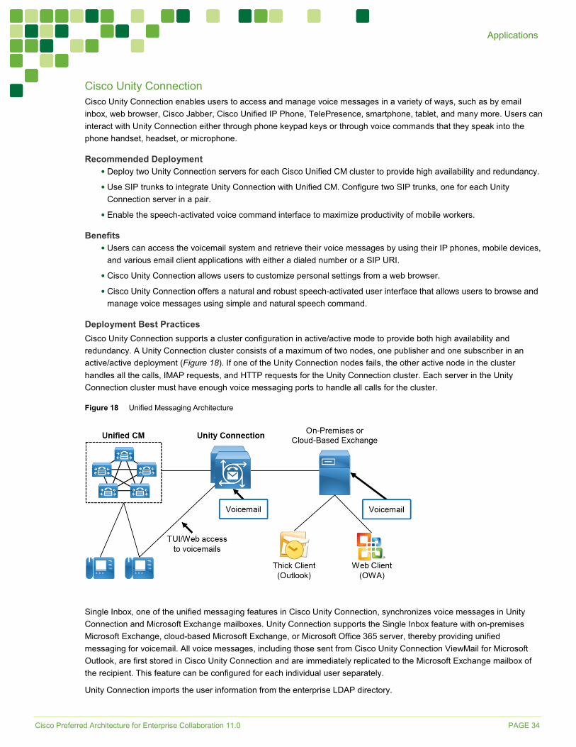
Cisco Preferred Architecture for Enterprise Collaboration 11.0 PAGE 34
Applications
Cisco Unity Connection Cisco Unity Connection enables users to access and manage voice messages in a variety of ways, such as by email inbox, web browser, Cisco Jabber, Cisco Unified IP Phone, TelePresence, smartphone, tablet, and many more. Users can interact with Unity Connection either through phone keypad keys or through voice commands that they speak into the phone handset, headset, or microphone.
Recommended Deployment • Deploy two Unity Connection servers for each Cisco Unified CM cluster to provide high availability and redundancy.
• Use SIP trunks to integrate Unity Connection with Unified CM. Configure two SIP trunks, one for each Unity Connection server in a pair.
• Enable the speech-activated voice command interface to maximize productivity of mobile workers.
Benefits • Users can access the voicemail system and retrieve their voice messages by using their IP phones, mobile devices,
and various email client applications with either a dialed number or a SIP URI.
• Cisco Unity Connection allows users to customize personal settings from a web browser.
• Cisco Unity Connection offers a natural and robust speech-activated user interface that allows users to browse and manage voice messages using simple and natural speech command.
Deployment Best Practices Cisco Unity Connection supports a cluster configuration in active/active mode to provide both high availability and redundancy. A Unity Connection cluster consists of a maximum of two nodes, one publisher and one subscriber in an active/active deployment (Figure 18). If one of the Unity Connection nodes fails, the other active node in the cluster handles all the calls, IMAP requests, and HTTP requests for the Unity Connection cluster. Each server in the Unity Connection cluster must have enough voice messaging ports to handle all calls for the cluster.
Figure 18 Unified Messaging Architecture
Single Inbox, one of the unified messaging features in Cisco Unity Connection, synchronizes voice messages in Unity Connection and Microsoft Exchange mailboxes. Unity Connection supports the Single Inbox feature with on-premises Microsoft Exchange, cloud-based Microsoft Exchange, or Microsoft Office 365 server, thereby providing unified messaging for voicemail. All voice messages, including those sent from Cisco Unity Connection ViewMail for Microsoft Outlook, are first stored in Cisco Unity Connection and are immediately replicated to the Microsoft Exchange mailbox of the recipient. This feature can be configured for each individual user separately.
Unity Connection imports the user information from the enterprise LDAP directory.

Cisco Preferred Architecture for Enterprise Collaboration 11.0 PAGE 35
Applications
Each mailbox must have a unique voicemail number. Unity Connection supports both E.164 and + E.164 formats for the extension of an end-user account (user with a voice mailbox). Unity Connection also supports alternate extensions per user.
The voicemail pilot number designates the directory number that users dial to access their voice messages. Unified CM automatically dials the voice messaging number when users press the Messages button on their phone. The voicemail pilot number can be an internal extension or a dedicated PSTN number.
Visual Voicemail allows users to access voicemail from the graphical interface on the IP phone. Users can view a list of messages and play messages from the list. Users can also compose, reply to, forward, and delete messages. Each voicemail message displays data including the date and time when the message was left, urgency level, and message length.
For more information on Cisco Unity Connection, refer to the product documentation.
Tools for Application Deployment Cisco Prime Collaboration Deployment (PCD) assists the administrator by automating many of the steps necessary to install a Unified CM cluster with IM and Presence Service and a Unity Connection cluster. It is deployed as a separate virtual machine (VM).
Cisco Prime License Manager (PLM) provides the administrator with a single license management point for Unified CM with IM and Presence and Unity Connection cluster(s). For enterprise deployments, we recommend deploying Cisco Prime License Manager as a standalone virtual machine (VM).
Cisco Preferred Architecture for Enterprise Collaboration 11.0 PAGE 36
Bandwidth Management
Bandwidth Management Bandwidth management is about ensuring the best possible user experience end-to-end for all voice and video capable endpoints, clients, and applications in the Collaboration solution. The Cisco Preferred Architecture for Enterprise Collaboration provides a holistic approach to bandwidth management that incorporates an end-to-end Quality of Service (QoS) architecture, call admission control, and video rate adaptation and resiliency mechanisms to ensure the best possible user experience for deploying pervasive video over managed and unmanaged networks.
QoS Architecture for Collaboration QoS ensures reliable, high-quality voice and video by reducing delay, packet loss, and jitter for media endpoints and applications. QoS provides a foundational network infrastructure technology that is required to support the transparent convergence of voice, video, and data networks. With the increasing amount of interactive applications – particularly voice, video, and immersive applications – real-time services are often required from the network. Because these resources are finite, they must be managed efficiently and effectively. If the number of flows contending for such priority resources were not limited, then as those resources become oversubscribed, the quality of all real-time traffic flows would degrade, eventually to the point of becoming useless. “Smart” media techniques, QoS, and admission control ensure that real-time applications and their related media do not over-subscribe the network and the bandwidth provisioned for those applications, thus ensuring efficient use of bandwidth resources. These smart media techniques coupled with QoS and, where needed, admission control can be a powerful set of tools to protect real-time media from non-real-time network traffic and to protect the network from oversubscription and the potential loss of user experience quality for all voice and video applications.
Figure 19 illustrates the approach to QoS used in the Cisco PA for Enterprise Collaboration. This approach consists of the following phases:
• Identification and classification — Refers to concepts of trust and techniques for identifying media and signaling for trusted and untrusted endpoints. It also includes the process of mapping the identified traffic to the correct DSCP to provide the media and signaling with the correct per-hop behavior end-to-end across the network for both trusted and untrusted endpoints.
• Queuing and scheduling — Consists of general WAN queuing and scheduling, the various types of queues, and recommendations for ensuring that collaboration media and signaling are correctly queued on egress to the WAN.
• Provisioning and admission control — Refers to provisioning the bandwidth in the network and determining the maximum bit rate that groups of endpoints will utilize. This is also where call admission control can be implemented in areas of the network where it is required.
• Monitoring, troubleshooting, and optimization — Ensures the proper operation and management of voice and video across the network. Cisco Prime Collaboration offers a suite of tools to perform these functions.
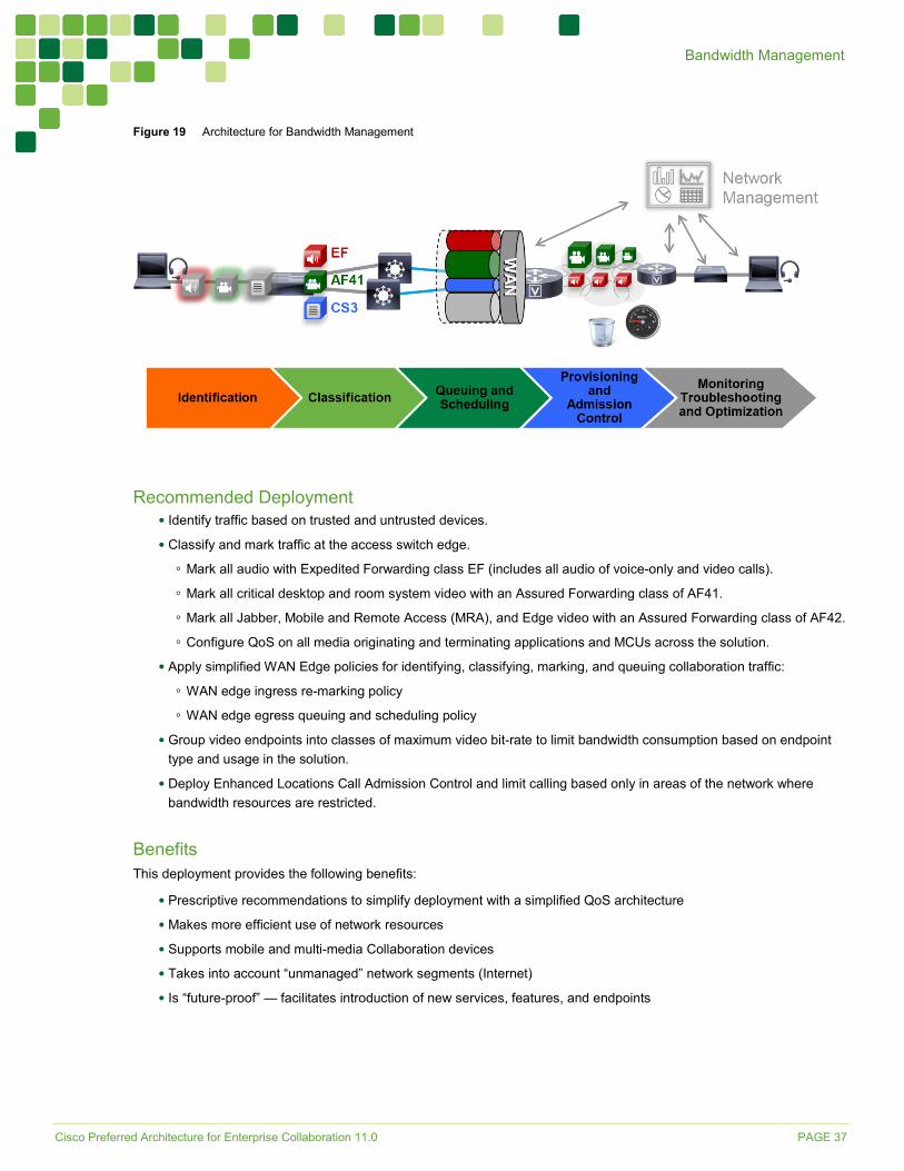
Cisco Preferred Architecture for Enterprise Collaboration 11.0 PAGE 37
Bandwidth Management
Figure 19 Architecture for Bandwidth Management
Recommended Deployment • Identify traffic based on trusted and untrusted devices.
• Classify and mark traffic at the access switch edge.
◦ Mark all audio with Expedited Forwarding class EF (includes all audio of voice-only and video calls).
◦ Mark all critical desktop and room system video with an Assured Forwarding class of AF41.
◦ Mark all Jabber, Mobile and Remote Access (MRA), and Edge video with an Assured Forwarding class of AF42.
◦ Configure QoS on all media originating and terminating applications and MCUs across the solution.
• Apply simplified WAN Edge policies for identifying, classifying, marking, and queuing collaboration traffic:
◦ WAN edge ingress re-marking policy
◦ WAN edge egress queuing and scheduling policy
• Group video endpoints into classes of maximum video bit-rate to limit bandwidth consumption based on endpoint type and usage in the solution.
• Deploy Enhanced Locations Call Admission Control and limit calling based only in areas of the network where bandwidth resources are restricted.
Benefits This deployment provides the following benefits:
• Prescriptive recommendations to simplify deployment with a simplified QoS architecture
• Makes more efficient use of network resources
• Supports mobile and multi-media Collaboration devices
• Takes into account “unmanaged” network segments (Internet)
• Is “future-proof” — facilitates introduction of new services, features, and endpoints

Cisco Preferred Architecture for Enterprise Collaboration 11.0 PAGE 38
Bandwidth Management
Deployment Best Practices When video is deployed pervasively across the organization, bandwidth constraints typically limit the video resolution that can be achieved during the busiest hour of the day, based on the bandwidth available and the number of video calls during that busy hour. While it is possible to buy more bandwidth in some places of the network, it is not always possible in all places of the network, nor is it cost effective to buy bandwidth that is used only during the busy hour but remains idle during the rest of the operational day.
To address this challenge, we have targeted a group of endpoints and call flows in the Preferred Architecture and have created a strategy of QoS marking and queuing to allow the video endpoints and flows to be more opportunistic in their utilization of video in the network. This concept of opportunistic video is about achieving the best video quality based on the WAN bandwidth resources available at any given time for a determined group of devices and call flows. In the Preferred Architecture all Cisco Jabber clients as well as any Collaboration Edge call flows such as mobile and remote access, business-to-business, and CMR Hybrid call flows are “classified” as opportunistic video flows. During the busy hour with higher call volumes, more video flows are expected over the constrained areas of the network. Rather than using call admission control to deny the video calls, we have created a QoS marking and queuing policy that forces opportunistic video flows to rate adapt down when packet loss occurs in that class. Using a single class video queue approach with DSCP-based Weighted Random Early Detection (WRED), we are able to protect prioritized video from packet loss during periods of congestion over opportunistic video. With this single video queue approach, when prioritized video is not using bandwidth in the queue, opportunistic video gains full access to the entire queue bandwidth if and when needed, or it rate adapts down to squeeze more opportunistic video flows into the queue without affecting the prioritized video flows. This is a significant point when deploying pervasive video with Jabber and Collaboration Edge technologies. This frees up more bandwidth for more video flows while still protecting prioritized video flows.
Another consideration taken in the Preferred Architecture is around the QoS of an audio stream of a video call, and how it has traditionally been marked with the same QoS as the video stream of the video call. This approach, however, has two deficiencies:
• The audio stream of a video call can be impacted by packet loss in the video queue.
• Audio stream classification for untrusted devices cannot be distinguished between voice-only calls and video calls.
In the Preferred Architecture we have designed a solution to address these deficiencies by ensuring that all audio is marked with a single value of Expedited Forwarding (EF) across the solution. In this way, whether the audio stream is associated with a voice-only call or a video call, it is always marked to the same value. Thus, the audio stream of a video call will be prioritized above the video and not subject to any packet loss in the video queue. This also solves the identification issue with untrusted devices such as Jabber clients. Because the marking of the client is not trusted by the network access layer, there is no effective way to distinguish the audio stream of a voice-only call from the audio of a video call in the network. Thus, moving to this new model where all audio is marked with a single value simplifies the network prioritization and treatment of the traffic.
Another consideration when the audio and video of a video call are not using the same QoS marking, is the fact that the audio could arrive at the terminating endpoint with less delay than video. This is because audio is prioritized higher and sent into the queues earlier than video traffic. To ensure that there are no lip-sync issues between the audio and video, enabling Real-time Transport Control Protocol (RTCP) on all endpoints is a simple yet strict requirement. RTCP uses timestamps to synchronize audio and video, and thus resolves any lip-sync issues that could arise from a delay variation between audio and video of the same video call.
In some areas of the network, bandwidth is too constrained even for the above strategy, in which case call admission control is the only possible way to ensure that over-subscription of bandwidth resources does not occur in those areas of the network. Enhanced Locations Call Admission Control can be deployed to protect the WAN resources, thus ensuring that any allowed call flows have the bandwidth to proceed without packet loss. If admission control fails a call flow, Unified CM has the ability to find alternative call routing paths if available.
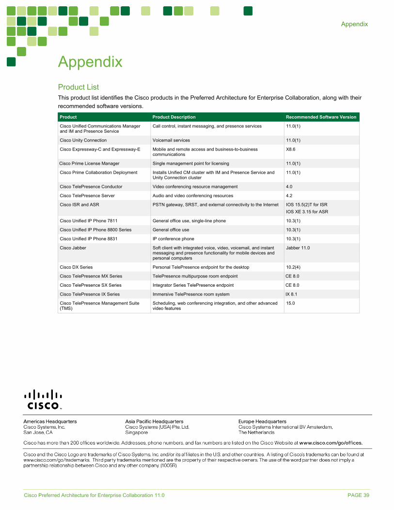
Cisco Preferred Architecture for Enterprise Collaboration 11.0 PAGE 39
Appendix
Appendix Product List This product list identifies the Cisco products in the Preferred Architecture for Enterprise Collaboration, along with their recommended software versions.
Product Product Description Recommended Software Version Cisco Unified Communications Manager and IM and Presence Service
Call control, instant messaging, and presence services 11.0(1)
Cisco Unity Connection Voicemail services 11.0(1) Cisco Expressway-C and Expressway-E Mobile and remote access and business-to-business
communications X8.6
Cisco Prime License Manager Single management point for licensing 11.0(1)
Cisco Prime Collaboration Deployment Installs Unified CM cluster with IM and Presence Service and Unity Connection cluster
11.0(1)
Cisco TelePresence Conductor Video conferencing resource management 4.0 Cisco TelePresence Server Audio and video conferencing resources 4.2 Cisco ISR and ASR PSTN gateway, SRST, and external connectivity to the Internet IOS 15.5(2)T for ISR
IOS XE 3.15 for ASR Cisco Unified IP Phone 7811 General office use, single-line phone 10.3(1)
Cisco Unified IP Phone 8800 Series General office use 10.3(1) Cisco Unified IP Phone 8831 IP conference phone 10.3(1)
Cisco Jabber Soft client with integrated voice, video, voicemail, and instant messaging and presence functionality for mobile devices and personal computers
Jabber 11.0
Cisco DX Series Personal TelePresence endpoint for the desktop 10.2(4) Cisco TelePresence MX Series TelePresence multipurpose room endpoint CE 8.0 Cisco TelePresence SX Series Integrator Series TelePresence endpoint CE 8.0 Cisco TelePresence IX Series Immersive TelePresence room system IX 8.1
Cisco TelePresence Management Suite (TMS)
Scheduling, web conferencing integration, and other advanced video features
15.0