cisco model dpc2320/epc2320 docsis/eurodocsis 2.0...
TRANSCRIPT
4042831 Rev A
Cisco Model DPC2320/EPC2320 DOCSIS/EuroDOCSIS 2.0 Wireless Residential Gateway
User Guide


Please Read
Important
Please read this entire guide. If this guide provides installation or operation instructions, give particular attention to all safety statements included in this guide.
Notices
Trademark Acknowledgments
Cisco and the Cisco logo are trademarks or registered trademarks of Cisco and/or its affiliates in the U.S. and other countries. A listing of Cisco's trademarks can be found at www.cisco.com/go/trademarks. DOCSIS is a registered trademark of Cable Television Laboratories, Inc. EuroDOCSIS is a trademark of Cable Television Laboratories, Inc.
Other third party trademarks mentioned are the property of their respective owners.
The use of the word partner does not imply a partnership relationship between Cisco and any other company. (1009R)
Publication Disclaimer
Cisco Systems, Inc. assumes no responsibility for errors or omissions that may appear in this publication. We reserve the right to change this publication at any time without notice. This document is not to be construed as conferring by implication, estoppel, or otherwise any license or right under any copyright or patent, whether or not the use of any information in this document employs an invention claimed in any existing or later issued patent.
Software and Firmware Use
The software described in this document is protected by copyright law and furnished to you under a license agreement. You may only use or copy this software in accordance with the terms of your license agreement.
The firmware in this equipment is protected by copyright law. You may only use the firmware in the equipment in which it is provided. Any reproduction or distribution of this firmware, or any portion of it, without our express written consent is prohibited.
Copyright
© 2011 Cisco Systems, Inc. All rights reserved. Printed in the United States of America.
Information in this publication is subject to change without notice. No part of this publication may be reproduced or transmitted in any form, by photocopy, microfilm, xerography, or any other means, or incorporated into any information retrieval system, electronic or mechanical, for any purpose, without the express permission of Cisco Systems, Inc.
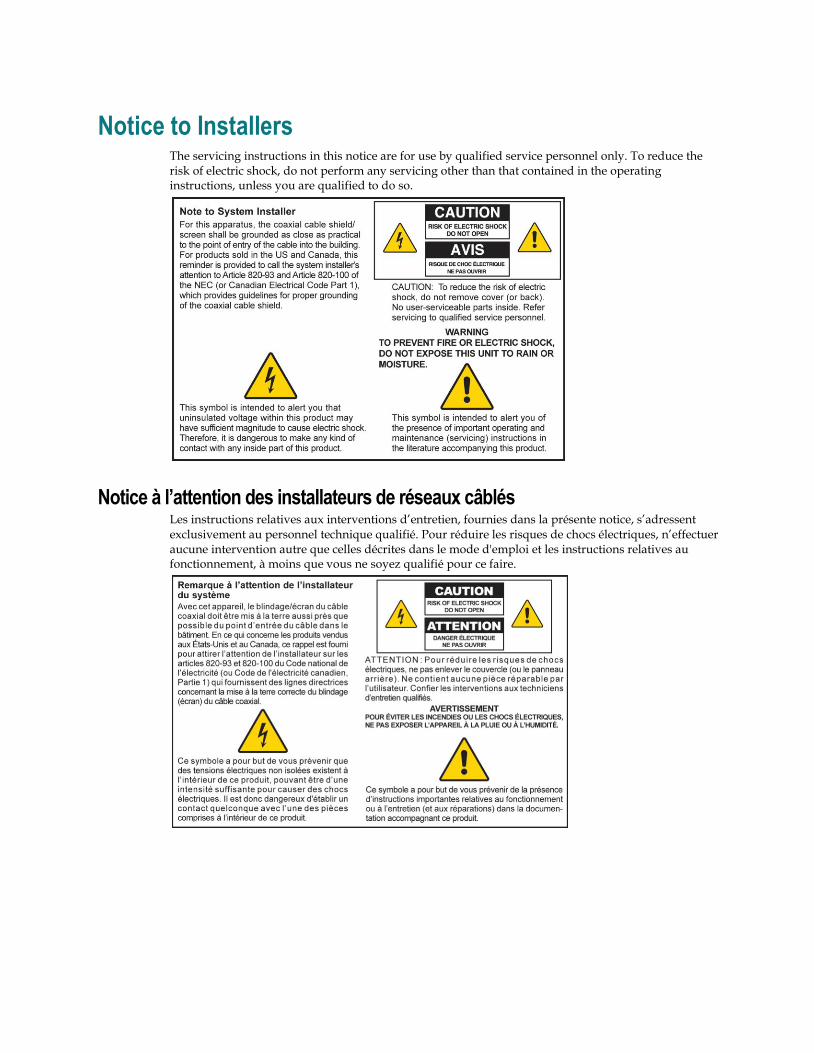
Notice to Installers The servicing instructions in this notice are for use by qualified service personnel only. To reduce the risk of electric shock, do not perform any servicing other than that contained in the operating instructions, unless you are qualified to do so.
Notice à l’attention des installateurs de réseaux câblés Les instructions relatives aux interventions d’entretien, fournies dans la présente notice, s’adressent exclusivement au personnel technique qualifié. Pour réduire les risques de chocs électriques, n’effectuer aucune intervention autre que celles décrites dans le mode d'emploi et les instructions relatives au fonctionnement, à moins que vous ne soyez qualifié pour ce faire.
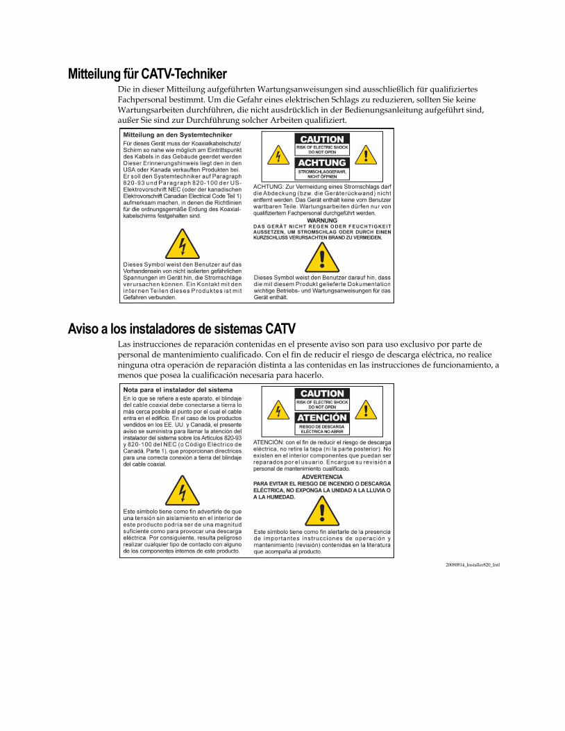
Mitteilung für CATV-Techniker Die in dieser Mitteilung aufgeführten Wartungsanweisungen sind ausschließlich für qualifiziertes Fachpersonal bestimmt. Um die Gefahr eines elektrischen Schlags zu reduzieren, sollten Sie keine Wartungsarbeiten durchführen, die nicht ausdrücklich in der Bedienungsanleitung aufgeführt sind, außer Sie sind zur Durchführung solcher Arbeiten qualifiziert.
Aviso a los instaladores de sistemas CATV Las instrucciones de reparación contenidas en el presente aviso son para uso exclusivo por parte de personal de mantenimiento cualificado. Con el fin de reducir el riesgo de descarga eléctrica, no realice ninguna otra operación de reparación distinta a las contenidas en las instrucciones de funcionamiento, a menos que posea la cualificación necesaria para hacerlo.
20080814_Installer820_Intl
4042831 Rev A iii
Contents
IMPORTANT SAFETY INSTRUCTIONS v
About This Guide xiii
Chapter 1 Introducing the DOCSIS Residential Gateway 1
Introduction .............................................................................................................................. 2 What's In the Carton? .............................................................................................................. 3 Front Panel Description .......................................................................................................... 4 Back Panel Description ............................................................................................................ 5
Chapter 2 Installing the DOCSIS Residential Gateway 7
Installation Preparations ......................................................................................................... 8 Install the Residential Gateway ........................................................................................... 14
Chapter 3 Configuring the DOCSIS Residential Gateway 17
Log in to the DOCSIS Residential Gateway for the First Time ....................................... 18 Configure Basic Settings ....................................................................................................... 21 Configure Advanced Settings .............................................................................................. 40 Configure Firewall Settings .................................................................................................. 62 Configure Parental Control Settings ................................................................................... 69 Configure Wireless Settings ................................................................................................. 78
Chapter 4 Operation of Front Panel Indicators 95
Initial Power Up, Calibration, and Registration (AC Power applied)............................ 96 Normal Operations (AC Power Applied) .......................................................................... 97 Special Conditions ................................................................................................................. 98
Chapter 5 Troubleshooting the DOCSIS Residential Gateway 99
Frequently Asked Questions .............................................................................................. 100 Common Troubleshooting Issues ...................................................................................... 105 Tips for Improved Performance ........................................................................................ 106

Contents
iv 4042831 Rev A
Chapter 6 Customer Information 107
Index 109
IMPORTANT SAFETY INSTRUCTIONS
4042831 Rev A v
IMPORTANT SAFETY INSTRUCTIONS 1) Read these instructions.
2) Keep these instructions.
3) Heed all warnings.
4) Follow all instructions.
5) Do not use this apparatus near water.
6) Clean only with dry cloth.
7) Do not block any ventilation openings. Install in accordance with the manufacturer's instructions.
8) Do not install near any heat sources such as radiators, heat registers, stoves, or other apparatus (including amplifiers) that produce heat.
9) Do not defeat the safety purpose of the polarized or grounding-type plug. A polarized plug has two blades with one wider than the other. A grounding-type plug has two blades and a third grounding prong. The wide blade or the third prong is provided for your safety. If the provided plug does not fit into your outlet, consult an electrician for replacement of the obsolete outlet.
10) Protect the power cord from being walked on or pinched particularly at plugs, convenience receptacles, and the point where they exit from the apparatus.
11) Only use attachments/accessories specified by the manufacturer.
12)
Use only with the cart, stand, tripod, bracket, or table specified by the manufacturer, or sold with the apparatus. When a cart is used, use caution when moving the cart/apparatus combination to avoid injury from tip-over.
13) Unplug this apparatus during lightning storms or when unused for long periods of time.
14) Refer all servicing to qualified service personnel. Servicing is required when the apparatus has been damaged in any way, such as a power-supply cord or plug is damaged, liquid has been spilled or objects have fallen into the apparatus, the apparatus has been exposed to rain or moisture, does not operate normally, or has been dropped.
Power Source Warning A label on this product indicates the correct power source for this product. Operate this product only from an electrical outlet with the voltage and frequency indicated on the product label. If you are uncertain of the type of power supply to your home or business, consult your service provider or your local power company.
The AC inlet on the unit must remain accessible and operable at all times.
Ground the Product
WARNING: Avoid electric shock and fire hazard! If this product connects to coaxial cable wiring, be sure the cable system is grounded (earthed). Grounding provides some protection against voltage surges and built-up static charges.
IMPORTANT SAFETY INSTRUCTIONS
vi 4042831 Rev A
Protect the Product from Lightning In addition to disconnecting the AC power from the wall outlet, disconnect the signal inputs.
Verify the Power Source from the On/Off Power Light When the on/off power light is not illuminated, the apparatus may still be connected to the power source. The light may go out when the apparatus is turned off, regardless of whether it is still plugged into an AC power source.
Eliminate AC Power/Mains Overloads
WARNING: Avoid electric shock and fire hazard! Do not overload AC power/mains, outlets, extension cords, or integral convenience receptacles. For products that require battery power or other power sources to operate them, refer to the operating instructions for those products.
Provide Ventilation and Select a Location
Remove all packaging material before applying power to the product.
Do not place this apparatus on a bed, sofa, rug, or similar surface.
Do not place this apparatus on an unstable surface.
Do not install this apparatus in an enclosure, such as a bookcase or rack, unless the installation provides proper ventilation.
Do not place entertainment devices (such as VCRs or DVDs), lamps, books, vases with liquids, or other objects on top of this product.
Do not block ventilation openings.
Operating Environment This product is designed for operation indoors with a temperature range from 32° to 104° F (0° to 40°C). Each product should have adequate spacing on all sides so that the cooling air vents on the chassis are not blocked.
Protect from Exposure to Moisture and Foreign Objects
WARNING: Avoid electric shock and fire hazard! Do not expose this product to dripping or splashing liquids, rain, or moisture. Objects filled with liquids, such as vases, should not be placed on this apparatus.
WARNING: Avoid electric shock and fire hazard! Unplug this product before cleaning. Do not use a liquid cleaner or an aerosol cleaner. Do not use a magnetic/static cleaning device (dust remover) to clean this product.
WARNING: Avoid electric shock and fire hazard! Never push objects through the openings in this product. Foreign objects can cause electrical shorts that can result in electric shock or fire.
IMPORTANT SAFETY INSTRUCTIONS
4042831 Rev A vii
Service Warnings
WARNING: Avoid electric shock! Do not open the cover of this product. Opening or removing the cover may expose you to dangerous voltages. If you open the cover, your warranty will be void. This product contains no user-serviceable parts.
Check Product Safety Upon completion of any service or repairs to this product, the service technician must perform safety checks to determine that this product is in proper operating condition.
Protect the Product When Moving It Always disconnect the power source when moving the apparatus or connecting or disconnecting cables.
Telephone Equipment Notice When using your telephone equipment, basic safety precautions should always be followed to reduce the risk of fire, electric stock and injury to persons, including the following:
1. Do not use this product near water, for example, near a bath tub, wash bowl, kitchen sink or laundry tub, in a wet basement or near a swimming pool.
2. Avoid using a telephone (other than a cordless type) during an electrical storm. There may be a remote risk of electric shock from lightning.
3. Do not use the telephone to report a gas leak in the vicinity of the leak.
CAUTION: To reduce the risk of fire, use only No. 26 AWG or larger telecommunication line cord.
SAVE THESE INSTRUCTIONS
20110316_Cable_Safety
20110316_Modem No Battery_Safety

United States FCC Compliance
4042831 Rev A ix
United States FCC Compliance This device has been tested and found to comply with the limits for a Class B digital device, pursuant to part 15 of the FCC Rules. These limits are designed to provide reasonable protection against such interference in a residential installation. This equipment generates, uses, and can radiate radio frequency energy. If not installed and used in accordance with the instructions, it may cause harmful interference to radio communications. However, there is no guarantee that interference will not occur in a particular installation. If this equipment does cause harmful interference to radio or television reception, which can be determined by turning the equipment OFF and ON, the user is encouraged to try to correct the interference by one or more of the following measures:
Reorient or relocate the receiving antenna.
Increase the separation between the equipment and receiver.
Connect the equipment into an outlet on a circuit different from that to which the receiver is connected.
Consult the service provider or an experienced radio/television technician for help.
Any changes or modifications not expressly approved by Cisco Systems, Inc., could void the user's authority to operate the equipment.
The information shown in the FCC Declaration of Conformity paragraph below is a requirement of the FCC and is intended to supply you with information regarding the FCC approval of this device. The phone numbers listed are for FCC-related questions only and not intended for questions regarding the connection or operation for this device. Please contact your service provider for any questions you may have regarding the operation or installation of this device.
Declaration of Conformity
This device complies with Part 15 of FCC Rules. Operation is subject to the following two conditions: 1) the device may not cause harmful interference, and 2) the device must accept any interference received, including interference that may cause undesired operation.
DOCSIS Residential Gateway Model(s): DPC2320 EPC2320
Manufactured by: Cisco Systems, Inc.
5030 Sugarloaf Parkway Lawrenceville, Georgia 30044 USA
Telephone: 770 236-1077
Canada EMI Regulation This Class B digital apparatus complies with Canadian ICES-003.
Cet appareil numérique de la class B est conforme à la norme NMB-003 du Canada.
United States FCC Compliance
x 4042831 Rev A
RF Exposure Statements Note: This transmitter must not be co-located or operated in conjunction with any other antenna or transmitter. This equipment should be installed and operated with a minimum distance of 7.9 inches (20 cm) between the radiator and your body.
US
This system has been evaluated for RF exposure for humans in reference to ANSI C 95.1 (American National Standards Institute) limits. The evaluation was based in accordance with FCC OET Bulletin 65C rev 01.01 in compliance with Part 2.1091 and Part 15.27. The minimum separation distance from the antenna to general bystander is 7.9 inches (20 cm) to maintain compliance.
Canada
This system has been evaluated for RF exposure for humans in reference to Canada Health Code 6 (2009) limits. The evaluation was based on evaluation per RSS-102 Rev 4. The minimum separation distance from the antenna to general bystander is 7.9 inches (20 cm) to maintain compliance.
EU
This system has been evaluated for RF exposure for humans in reference to the ICNIRP (International Commission on Non-Ionizing Radiation Protection) limits. The evaluation was based on the EN 50385 Product Standard to Demonstrate Compliance of Radio Base Stations and Fixed Terminals for Wireless Telecommunications Systems with basic restrictions or reference levels related to Human Exposure to Radio Frequency Electromagnetic Fields from 300 MHz to 40 GHz. The minimum separation distance from the antenna to general bystander is 20 cm (7.9 inches).
Australia
This system has been evaluated for RF exposure for humans as referenced in the Australian Radiation Protection standard and has been evaluated to the ICNIRP (International Commission on Non-Ionizing Radiation Protection) limits. The minimum separation distance from the antenna to general bystander is 20 cm (7.9 inches).
20100527 FCC DSL_Dom and Intl
CE Compliance
4042831 Rev A xi
CE Compliance
Declaration of Conformity with Regard to the EU Directive 1999/5/EC (R&TTE Directive)
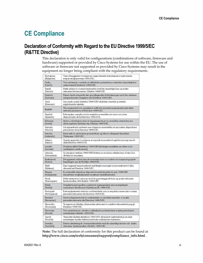
This declaration is only valid for configurations (combinations of software, firmware and hardware) supported or provided by Cisco Systems for use within the EU. The use of software or firmware not supported or provided by Cisco Systems may result in the equipment no longer being compliant with the regulatory requirements.
Note: The full declaration of conformity for this product can be found at http://www.cisco.com/web/consumer/support/compliance_info.html.
CE Compliance
xii 4042831 Rev A
The following standards were applied during the assessment of the product against the requirements of the Directive 1999/5/EC:
Radio: EN 300 328
EMC: EN 301 489-1 and EN 301 489-17
Safety: EN 60950 and EN 50385
The CE mark and class-2 identifier are affixed to the product and its packaging. This product conforms to the following European directives:
-1999/5/EC
National Restrictions This product is for indoor use only.
France
For 2.4 GHz, the output power is restricted to 10 mW EIRP when the product is used outdoors in the band 2454 - 2483.5 MHz. There are no restrictions when used in other parts of the 2.4 GHz band. Check http://www.arcep.fr/ for more details.
Pour la bande 2,4 GHz, la puissance est limitée à 10 mW en p.i.r.e. pour les équipements utilisés en extérieur dans la bande 2454 - 2483,5 MHz. Il n'y a pas de restrictions pour des utilisations dans d'autres parties de la bande 2,4 GHz. Consultez http://www.arcep.fr/ pour de plus amples détails.
Italy
This product meets the National Radio Interface and the requirements specified in the National Frequency Allocation Table for Italy. Unless this wireless LAN product is operating within the boundaries of the owner's property, its use requires a ―general authorization.‖ Please check http://www.comunicazioni.it/it/ for more details.
Questo prodotto è conforme alla specifiche di Interfaccia Radio Nazionali e rispetta il Piano Nazionale di ripartizione delle frequenze in Italia. Se non viene installato all 'interno del proprio fondo, l'utilizzo di prodotti Wireless LAN richiede una ―Autorizzazione Generale‖. Consultare http://www.comunicazioni.it/it/ per maggiori dettagli.
Latvia
The outdoor usage of the 2.4 GHz band requires an authorization from the Electronic Communications Office. Please check http://www.esd.lv for more details.
2,4 GHz frekvenču joslas izmantošanai ārpus telpām nepieciešama atļauja no Elektronisko sakaru direkcijas. Vairāk informācijas: http://www.esd.lv.
Note: The regulatory limits for maximum output power are specified in EIRP. The EIRP level of a device can be calculated by adding the gain of the antenna used (specified in dBi) to the output power available at the connector (specified in dBm).
Antennas Use only the antenna supplied with the product.
20110311_CE_Modem/EMTA
About This Guide
4042831 Rev A xiii
About This Guide
Introduction
Welcome. This guide provides instructions and recommendations for placing, installing, configuring, operating, maintaining, and troubleshooting the DPC2320 and EPC2320 DOCSIS Residential Gateways.
Purpose
This guide covers the following product models:
DPC2320 DOCSIS Residential Gateway
EPC2320 EuroDOCSIS Residential Gateway
All features described in this guide are standard to these models of residential gateways unless otherwise noted. For the purpose of this guide, whenever a feature or option applies to only a specific model, the model number is specified. If a model number is not specified, then the feature or option applies to both of the models.
Audience
This guide is written for the home subscriber.
Document Version
This is the first formal release of this document.

4042831 Rev A 1
Introduction
This chapter provides an overview of residential gateway features, indicators, and connectors to help you become familiar with the residential gateway and the benefits it offers. This chapter also lists the accessories and equipment that are provided with the residential gateway so you can verify that you received all of these items.
1 Chapter 1 Introducing the DOCSIS Residential Gateway
In This Chapter
Introduction ............................................................................................. 2
What's In the Carton? ............................................................................. 3
Front Panel Description ......................................................................... 4
Back Panel Description .......................................................................... 5
Chapter 1 Introducing the DOCSIS Residential Gateway
2 4042831 Rev A
Introduction Welcome to the exciting world of high-speed Internet service. Your new Cisco® Model DPC2320 DOCSIS® 2.0 or EPC2320 EuroDOCSIS™ 2.0 Residential Gateway is a cable modem that meets industry standards for high-speed data connectivity. It can simultaneously provide wired (Ethernet) and wireless gateway capabilities to support high-speed data access—all in one device. These capabilities allow you to connect to a variety of devices in your home or small office. With a residential gateway, your Internet enjoyment, home and business communications, and personal productivity will surely soar.
This guide provides procedures and recommendations for placing, installing, configuring, operating, and troubleshooting your DPC2320 and EPC2320 residential gateway for high-speed Internet for your home or office. Refer to the appropriate section in this guide for the specific information you need for your situation. Contact your service provider for more information about subscribing to these services.
Your new residential gateway offers the following outstanding benefits and features:
Compliant with DOCSIS 2.0, and 1.x standards to deliver high-end performance and reliability
High performance broadband Internet connectivity to energize your online experience
One 10/100 BASE-T Ethernet ports to provide wired connectivity
802.11n Wireless Access Point
Wireless Protected Setup (WPS), including a push button switch to activate WPS for simplified and secure wireless setup
A Wireless ON/OFF button (optional) to easily enable and disable the wireless feature
User configurable Parental Control blocks access to undesirable Internet sites
Advanced firewall technology deters hackers and protects the home network from unauthorized access
Attractive compact design that allows for vertical, horizontal, or wall-mounted operation
Color-coded interface ports and corresponding cables simplify installation and setup
DOCSIS-5 compliant LED labeling and behavior provides a user and technician friendly method to check operational status and act as a troubleshooting tool
Allows automatic software upgrades by your service provider
What's In the Carton?
4042831 Rev A 3
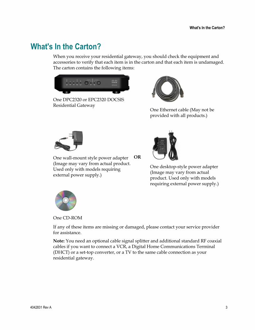
What's In the Carton? When you receive your residential gateway, you should check the equipment and accessories to verify that each item is in the carton and that each item is undamaged. The carton contains the following items:
One DPC2320 or EPC2320 DOCSIS Residential Gateway
One Ethernet cable (May not be provided with all products.)
One wall-mount style power adapter (Image may vary from actual product. Used only with models requiring external power supply.)
OR
One desktop-style power adapter (Image may vary from actual product. Used only with models requiring external power supply.)
One CD-ROM
If any of these items are missing or damaged, please contact your service provider for assistance.
Note: You need an optional cable signal splitter and additional standard RF coaxial cables if you want to connect a VCR, a Digital Home Communications Terminal (DHCT) or a set-top converter, or a TV to the same cable connection as your residential gateway.
Chapter 1 Introducing the DOCSIS Residential Gateway
4 4042831 Rev A
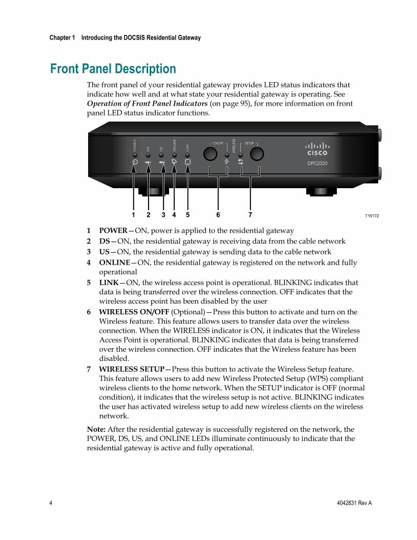
Front Panel Description The front panel of your residential gateway provides LED status indicators that indicate how well and at what state your residential gateway is operating. See Operation of Front Panel Indicators (on page 95), for more information on front panel LED status indicator functions.
1 POWER—ON, power is applied to the residential gateway
2 DS—ON, the residential gateway is receiving data from the cable network
3 US—ON, the residential gateway is sending data to the cable network
4 ONLINE—ON, the residential gateway is registered on the network and fully operational
5 LINK—ON, the wireless access point is operational. BLINKING indicates that data is being transferred over the wireless connection. OFF indicates that the wireless access point has been disabled by the user
6 WIRELESS ON/OFF (Optional)—Press this button to activate and turn on the Wireless feature. This feature allows users to transfer data over the wireless connection. When the WIRELESS indicator is ON, it indicates that the Wireless Access Point is operational. BLINKING indicates that data is being transferred over the wireless connection. OFF indicates that the Wireless feature has been disabled.
7 WIRELESS SETUP—Press this button to activate the Wireless Setup feature. This feature allows users to add new Wireless Protected Setup (WPS) compliant wireless clients to the home network. When the SETUP indicator is OFF (normal condition), it indicates that the wireless setup is not active. BLINKING indicates the user has activated wireless setup to add new wireless clients on the wireless network.
Note: After the residential gateway is successfully registered on the network, the POWER, DS, US, and ONLINE LEDs illuminate continuously to indicate that the residential gateway is active and fully operational.
Back Panel Description
4042831 Rev A 5
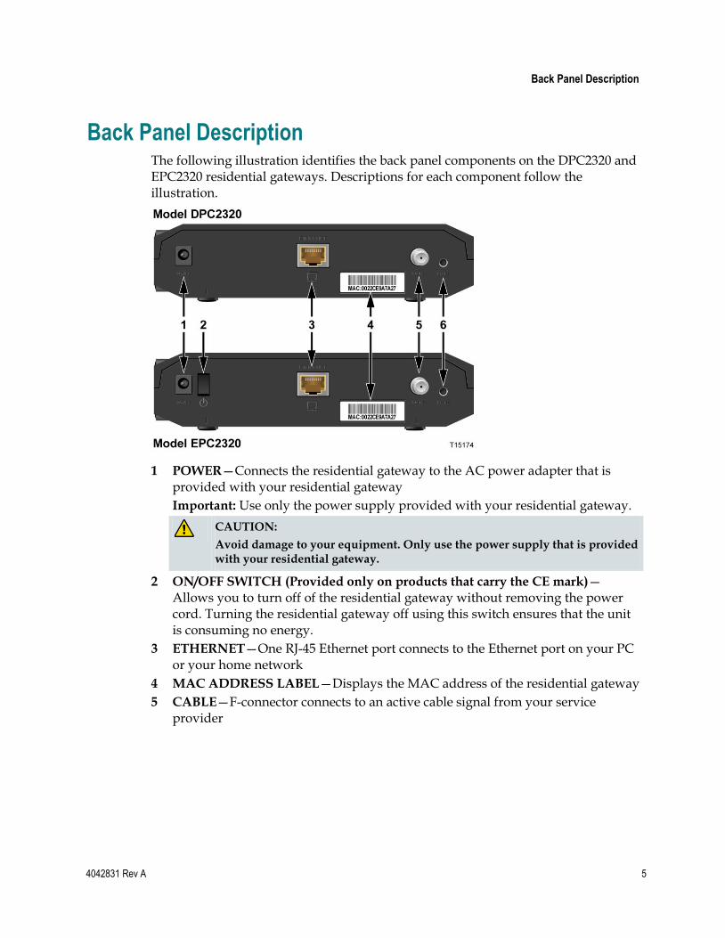
Back Panel Description The following illustration identifies the back panel components on the DPC2320 and EPC2320 residential gateways. Descriptions for each component follow the illustration.
1 POWER—Connects the residential gateway to the AC power adapter that is provided with your residential gateway
Important: Use only the power supply provided with your residential gateway.
CAUTION:
Avoid damage to your equipment. Only use the power supply that is provided with your residential gateway.
2 ON/OFF SWITCH (Provided only on products that carry the CE mark)—Allows you to turn off of the residential gateway without removing the power cord. Turning the residential gateway off using this switch ensures that the unit is consuming no energy.
3 ETHERNET—One RJ-45 Ethernet port connects to the Ethernet port on your PC or your home network
4 MAC ADDRESS LABEL—Displays the MAC address of the residential gateway
5 CABLE—F-connector connects to an active cable signal from your service provider
Chapter 1 Introducing the DOCSIS Residential Gateway
6 4042831 Rev A
6 RESET—A momentary pressing (1-2 seconds) of this switch restarts (power cycles) the device. Pressing and holding the switch for more than ten seconds first causes a reset-to-factory-default of all settings and then restarts (power cycles) the device
CAUTION:
The RESET button is for maintenance purposes only. Do not use unless instructed to do so by your service provider. Doing so may cause you to lose any settings you have selected.
4042831 Rev A 7
Introduction
This chapter describes how to properly install the residential gateway and to connect the residential gateway to a computer and other devices.
2 Chapter 2 Installing the DOCSIS Residential Gateway
In This Chapter
Installation Preparations ........................................................................ 8
Install the Residential Gateway .......................................................... 14
Chapter 2 Installing the DOCSIS Residential Gateway
8 4042831 Rev A
Installation Preparations Before installing the residential gateway, make sure that your system meets or exceeds the requirements listed in this section. Also, make sure that you have prepared your home and home devices as described in this section.
What Are the System Requirements for Internet Service?
To ensure that your residential gateway operates efficiently for high-speed Internet service, you must have an Internet-capable PC, Mac, or Internet appliance equipped with an Ethernet port. To access the user guide for this product, you must have a CD-ROM drive.
Note: You will also need an active cable input line and an Internet connection.
What Types of Service Accounts Do I Need?
Depending upon the features your service provider offers, you may need to establish one or both of the following accounts:
A high-speed Internet access account, if your residential gateway supports an Internet connection
An account for telephone service, if your residential gateway supports digital telephone service
Refer to one of the following topics to learn more about the types of service accounts that you may need to establish.
High-Speed Internet Access Account
If you do not have a high-speed Internet access account, your service provider will set up your account and become your Internet Service Provider (ISP). Internet access enables you to send and receive e-mail, access the World Wide Web, and receive other Internet services.
You will need to give your service provider information about the residential gateway in order to use the high-speed internet feature that this product offers. Refer to Information Your Service Provider Needs (on page 9) to learn how to locate the information your service provider needs to establish a high-speed Internet access account for the residential gateway
If you have an existing high-speed Internet access account, you will need to give your service provider the serial number and MAC address of the residential gateway in order to use the high-speed internet feature that this product offers. Refer to Information Your Service Provider Needs (on page 9) to learn how to locate this information.
Installation Preparations
4042831 Rev A 9
Information Your Service Provider Needs
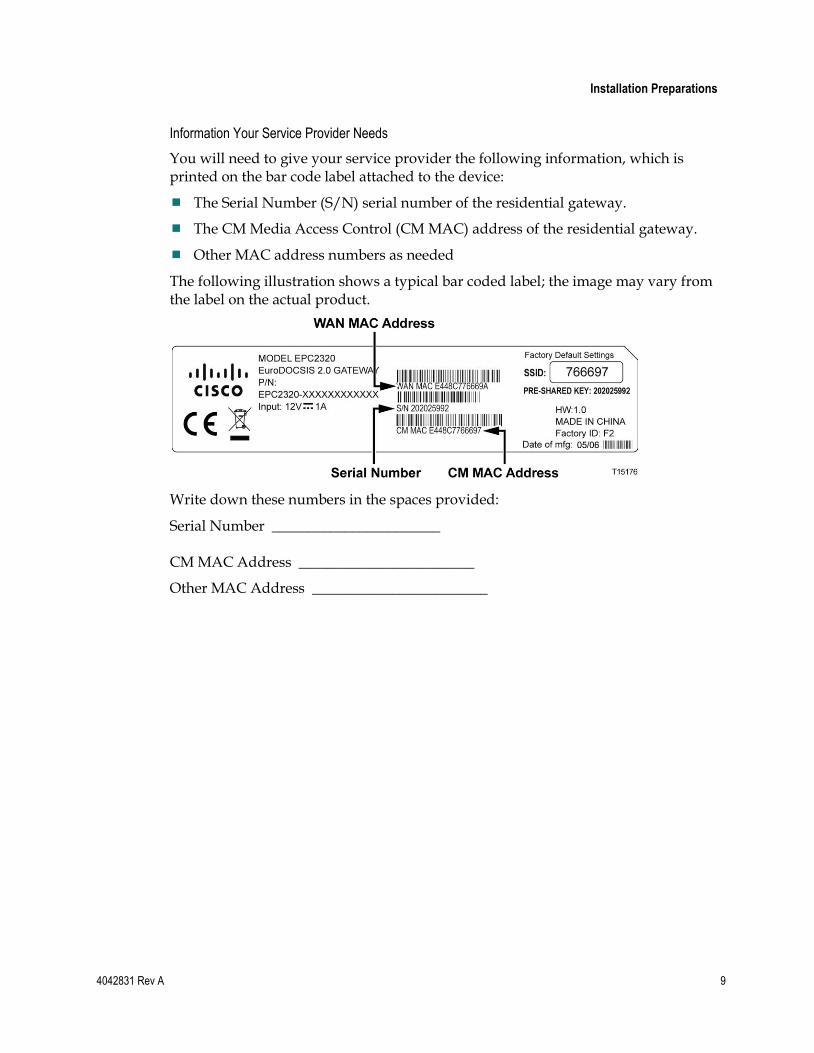
You will need to give your service provider the following information, which is printed on the bar code label attached to the device:
The Serial Number (S/N) serial number of the residential gateway.
The CM Media Access Control (CM MAC) address of the residential gateway.
Other MAC address numbers as needed
The following illustration shows a typical bar coded label; the image may vary from the label on the actual product.
Write down these numbers in the spaces provided:
Serial Number _______________________ CM MAC Address ________________________
Other MAC Address ________________________
Chapter 2 Installing the DOCSIS Residential Gateway
10 4042831 Rev A
Where Is the Best Location for My Residential Gateway?
The ideal location for your residential gateway is where it has access to outlets and other devices. Think about the layout of your home or office, and consult with your service provider to select the best location for your residential gateway. Read this user guide thoroughly before you decide where to place your residential gateway.
Consider these recommendations:
Choose a location close to your computer if you will also use the residential gateway for high-speed Internet service.
Choose a location that is near an existing RF coaxial connection to eliminate the need for an additional RF coaxial outlet.
Choose a location that is relatively protected from accidental disturbance or harm, such as a closet, basement, or other protected area.
Choose a location so that there is plenty of room to guide the cables away from the residential gateway without straining or crimping them.
Choose a location that allows adequate ventilation around the residential gateway.
How Do I Mount the Residential Gateway on a Wall? (Optional)
If you wish, you can mount the residential gateway to a wall. This section describes how to mount the residential gateway to a wall, and includes a list of equipment you will need along with suggestions for choosing an appropriate place to mount the residential gateway.
Select an Appropriate Place to Mount the Residential Gateway
You may mount the residential gateway to a wall that is made of cement, wood, or drywall. When choosing an appropriate mounting place, refer to the following recommendations:
Ensure that the mounting location is free of obstructions on all sides, and the cables should be able to easily reach the residential gateway without strain.
Leave sufficient clearance between the bottom of the residential gateway and any flooring or shelving underneath to allow access to cabling.
Allow enough slack in all cables so that the residential gateway can be removed for any required maintenance without disconnecting the cables.
Choose a location that allows adequate ventilation around the residential gateway.
Installation Preparations
4042831 Rev A 11
Equipment Needed
Verify that you have the following items that you will need to mount the residential gateway:
Two wall anchors for #8 x 1-inch screws
Two #8 x 1-inch pan head sheet metal screws
Drill with a 3/16-in. wood or masonry bit, as appropriate for the wall composition
A copy of the wall-mounting illustrations shown on the following pages
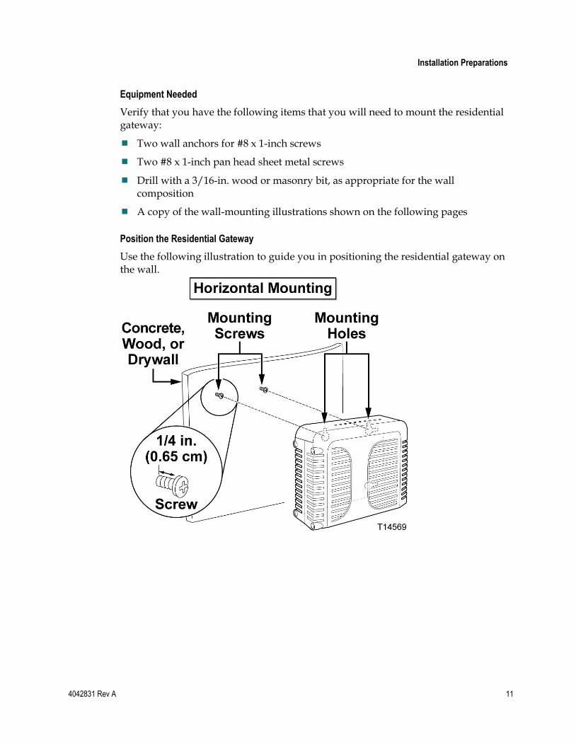
Position the Residential Gateway
Use the following illustration to guide you in positioning the residential gateway on the wall.
Chapter 2 Installing the DOCSIS Residential Gateway
12 4042831 Rev A
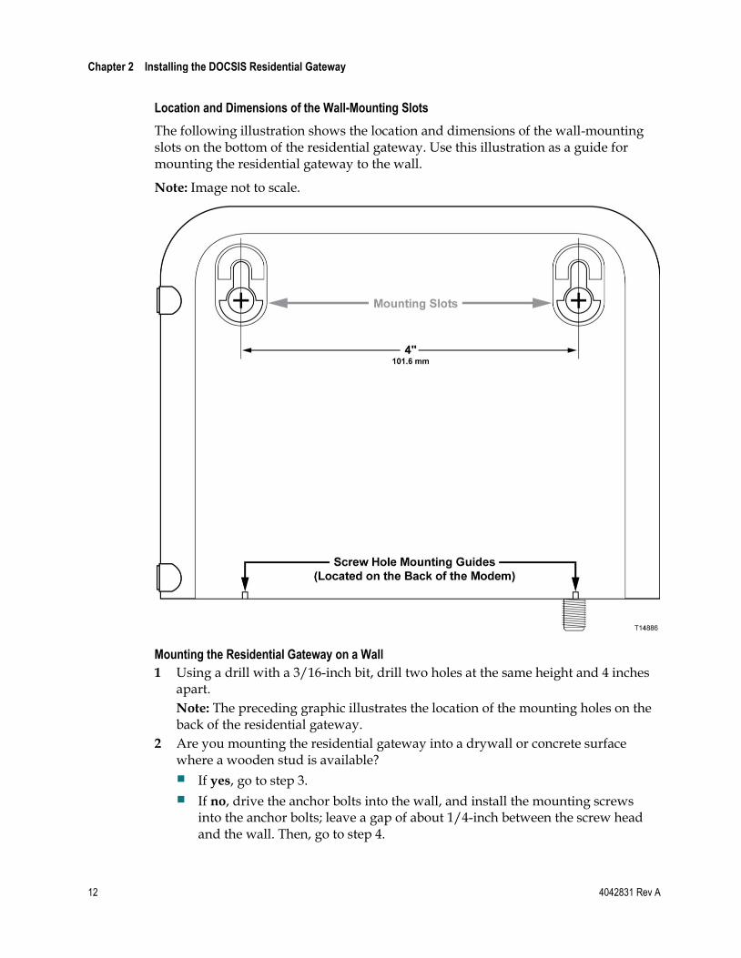
Location and Dimensions of the Wall-Mounting Slots
The following illustration shows the location and dimensions of the wall-mounting slots on the bottom of the residential gateway. Use this illustration as a guide for mounting the residential gateway to the wall.
Note: Image not to scale.
Mounting the Residential Gateway on a Wall
1 Using a drill with a 3/16-inch bit, drill two holes at the same height and 4 inches apart.
Note: The preceding graphic illustrates the location of the mounting holes on the back of the residential gateway.
2 Are you mounting the residential gateway into a drywall or concrete surface where a wooden stud is available?
If yes, go to step 3.
If no, drive the anchor bolts into the wall, and install the mounting screws into the anchor bolts; leave a gap of about 1/4-inch between the screw head and the wall. Then, go to step 4.
Installation Preparations
4042831 Rev A 13
3 Install the mounting screws into the wall; leave a gap of about 1/4-inch between the screw head and the wall. Then, go to step 4.
4 Verify that no cables or wires are connected to the residential gateway.
5 Lift the residential gateway into position. Slip the large end of both mounting slots (located in the back of the residential gateway) over the mounting screws, and then slide the residential gateway down until the narrow end of the keyhole slot contacts the screw shaft.
Important: Verify that the mounting screws securely support the residential gateway before you release the unit.
Chapter 2 Installing the DOCSIS Residential Gateway
14 4042831 Rev A
Install the Residential Gateway This section describes how to connect your residential gateway to support the services that the residential gateway offers.
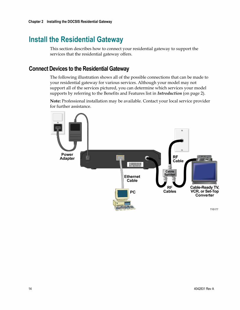
Connect Devices to the Residential Gateway
The following illustration shows all of the possible connections that can be made to your residential gateway for various services. Although your model may not support all of the services pictured, you can determine which services your model supports by referring to the Benefits and Features list in Introduction (on page 2).
Note: Professional installation may be available. Contact your local service provider for further assistance.
Install the Residential Gateway
4042831 Rev A 15
Connect the Residential Gateway
The following installation procedure ensures proper setup and configuration for the residential gateway.
1 Choose an appropriate and safe location to install the residential gateway (close to a power source, an active cable connection, and your PC-if using high-speed Internet). For assistance, go to Where Is the Best Location for My Residential Gateway? (on page 10).
WARNING:
To avoid personal injury, follow the installation instructions in the exact order shown.
Wiring and connections must be properly insulated to prevent electrical shock.
Disconnect power from the residential gateway before attempting to connect to any device.
2 Power off your PC and other networking device; then, unplug them from the power source.
3 Connect the active RF coaxial cable from your service provider to the coax connector labeled CABLE on the back of the residential gateway.
Note: To connect a TV, DHCT, set-top, or VCR from the same cable connection, you will need to install a cable signal splitter (not included). Always check with your service provider before using a splitter as a splitter may degrade the signal.
4 Connect your PC to the residential gateway using either of the following connections:
Ethernet Connection: Locate the yellow Ethernet cable, connect one end of the Ethernet cable to the Ethernet port on your PC, and connect the other end to the yellow ETHERNET port on the back of the residential gateway.
Note: To install more Ethernet devices than ports provided on the residential gateway, use an external mulit-port Ethernet switch(s).
Wireless: Make sure that your wireless device is powered up. You will need to associate your wireless device with the wireless residential gateway once the residential gateway is operational. Follow the directions provided for your wireless device for associating with a wireless access point. If the residential gateway has a WIRELESS ON/OFF button, make sure that WIRELESS is enabled by confirming that the ON/OFF indicator is ON. If the indicator is OFF, press the ON/OFF button to enable the WIRELESS feature.
More information about the factory default configuration of your wireless residential gateway can be found later in this guide in Configure Wireless Settings.
Chapter 2 Installing the DOCSIS Residential Gateway
16 4042831 Rev A
5 Locate the AC power cord provided with your residential gateway. Insert one end of the power cord into the AC connector on the back of the residential gateway. Then, plug the AC power cord into an AC outlet to power-up the residential gateway. The residential gateway will perform an automatic search to locate and sign on to the broadband data network. This process may take up to 2-5 minutes. The residential gateway will be ready for use when the POWER, DS, US and ONLINE LEDs on the front panel of the residential gateway stop blinking and remain on continuously.
6 Plug in and power on your PC and other home network devices. The LINK LED on the residential gateway corresponding to the connected devices should be on or blinking.
7 Once your residential gateway is online, most Internet devices will have immediate Internet access.
Note: If your PC does not have Internet access, refer to How Do I Configure TCP/IP Protocol? (on page 100) for information on how to configure your PC for TCP/IP. For Internet devices other than PCs, refer to the DHCP or IP Address configuration section of the User Guide or Operations Manual for those devices.
4042831 Rev A 17
Introduction
This chapter provides instructions for using the WebWizard to configure the residential gateway to operate correctly.
The WebWizard gives you access to residential gateway settings that were configured at the factory for the most common installation configurations. After you access the WebWizard, you can customize these settings to meet your needs. The WebWizard pages in this chapter are organized in the order shown on the Setup page.
When using the instructions in this chapter, keep in mind that examples of the WebWizard pages shown here are for illustration purposes only and may differ from the WebWizard pages shown on your residential gateway. The pages shown in this guide also represent the default values for the residential gateway.
Important: If you are not familiar with the network configuration procedures detailed in this chapter, contact your service provider before attempting to change any of the residential gateway settings.
3 Chapter 3 Configuring the DOCSIS Residential Gateway
In This Chapter
Log in to the DOCSIS Residential Gateway for the First Time ...... 18
Configure Basic Settings ...................................................................... 21
Configure Advanced Settings ............................................................. 40
Configure Firewall Settings ................................................................. 62
Configure Parental Control Settings .................................................. 69
Configure Wireless Settings ................................................................ 78
Chapter 3 Configuring the DOCSIS Residential Gateway
18 4042831 Rev A
Log in to the DOCSIS Residential Gateway for the First Time
This section provides detailed instructions for logging in to the residential gateway so that you can use the WebWizard to customize the residential gateway to suit your needs, rather than using the default (factory) settings.
The residential gateway uses a default IP address of 192.168.0.1. If you have connected the residential gateway correctly and you have configured your computer properly, use the following procedure to log in to the residential gateway as an administrator.
Accessing the Residential Gateway
You must access the WebWizard in order to configure the residential gateway. To gain access to the WebWizard, use the web browser on the PC attached to the gateway and complete the following steps.
1 Open the web browser on your PC.
2 Type the following IP address and then select Go: http://192.168.0.1.
3 The web browser accesses the WebWizard and displays the default About Your
Modem page. This page displays information about your cable modem along with a series of tabs for accessing other WebWizard configuration and operation features.
Log in to the DOCSIS Residential Gateway for the First Time
4042831 Rev A 19
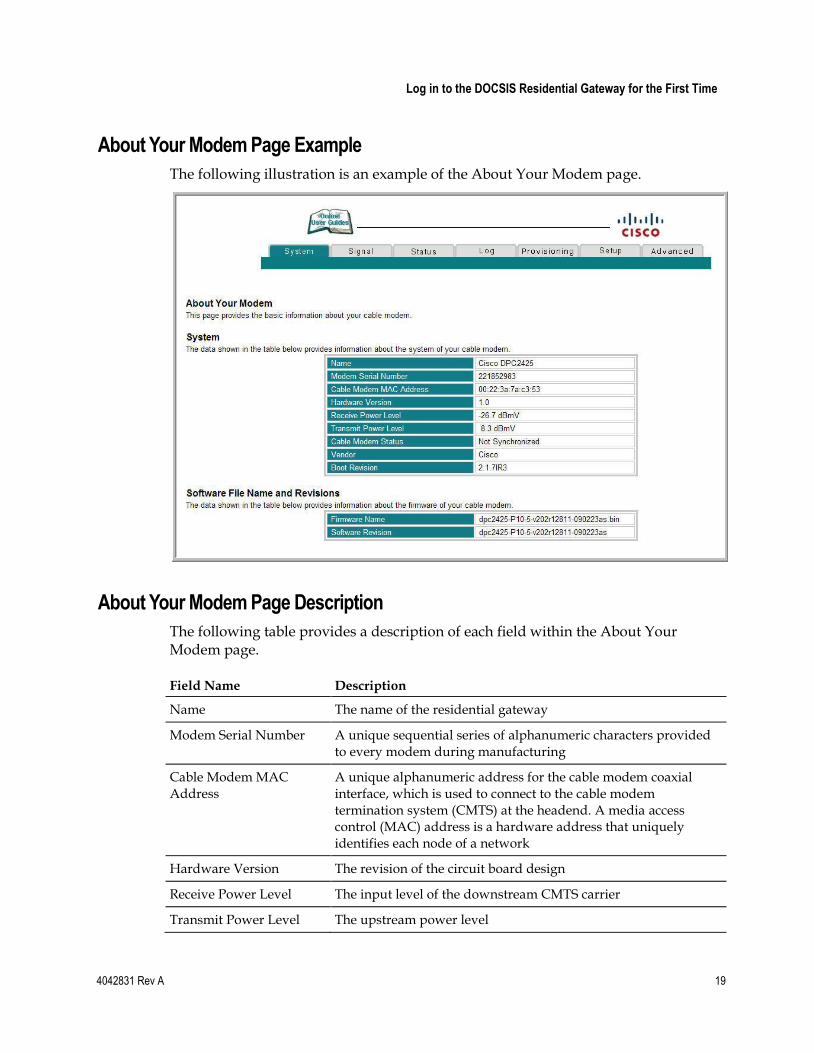
About Your Modem Page Example
The following illustration is an example of the About Your Modem page.
About Your Modem Page Description
The following table provides a description of each field within the About Your Modem page.
Field Name Description
Name The name of the residential gateway
Modem Serial Number A unique sequential series of alphanumeric characters provided to every modem during manufacturing
Cable Modem MAC Address
A unique alphanumeric address for the cable modem coaxial interface, which is used to connect to the cable modem termination system (CMTS) at the headend. A media access control (MAC) address is a hardware address that uniquely identifies each node of a network
Hardware Version The revision of the circuit board design
Receive Power Level The input level of the downstream CMTS carrier
Transmit Power Level The upstream power level
Chapter 3 Configuring the DOCSIS Residential Gateway
20 4042831 Rev A
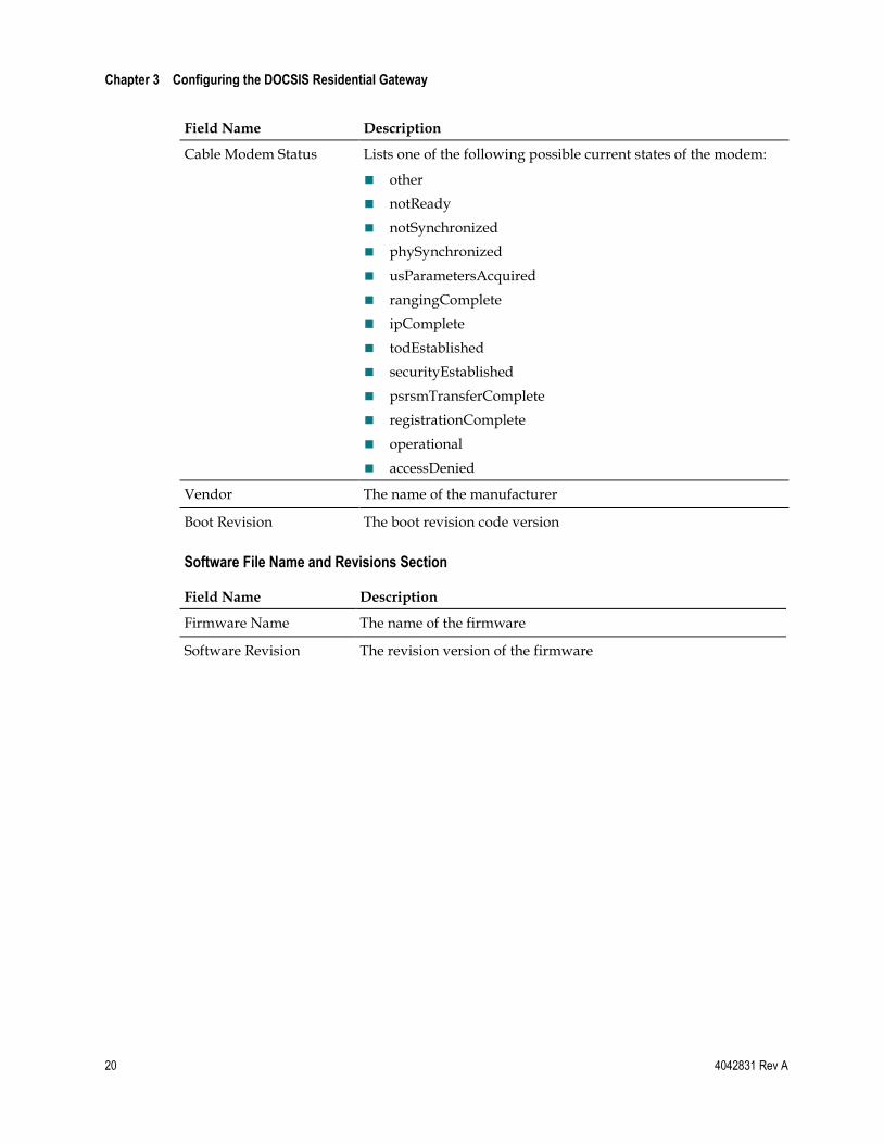
Field Name Description
Cable Modem Status Lists one of the following possible current states of the modem:
other
notReady
notSynchronized
phySynchronized
usParametersAcquired
rangingComplete
ipComplete
todEstablished
securityEstablished
psrsmTransferComplete
registrationComplete
operational
accessDenied
Vendor The name of the manufacturer
Boot Revision The boot revision code version
Software File Name and Revisions Section
Field Name Description
Firmware Name The name of the firmware
Software Revision The revision version of the firmware
Configure Basic Settings
4042831 Rev A 21
Configure Basic Settings This section describes how to configure Basic settings for the residential gateway.
Setting Configuration Options
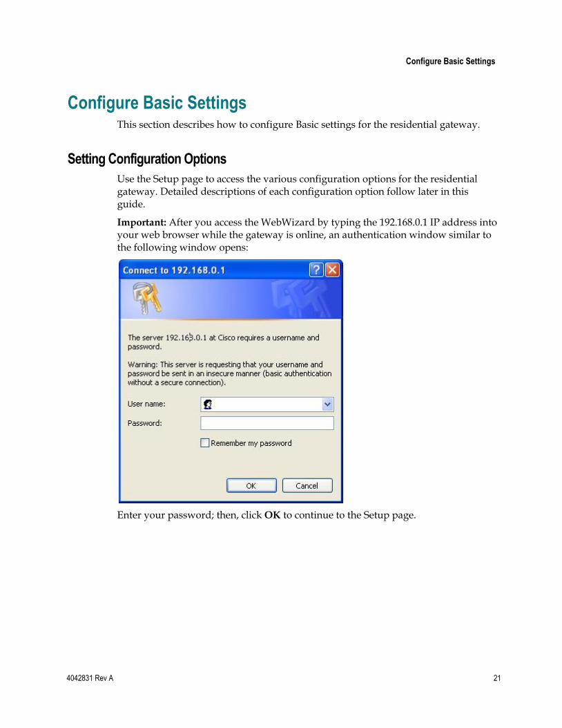
Use the Setup page to access the various configuration options for the residential gateway. Detailed descriptions of each configuration option follow later in this guide.
Important: After you access the WebWizard by typing the 192.168.0.1 IP address into your web browser while the gateway is online, an authentication window similar to the following window opens:
Enter your password; then, click OK to continue to the Setup page.
Chapter 3 Configuring the DOCSIS Residential Gateway
22 4042831 Rev A
First Time Users
The gateway ships from the factory without a factory-assigned or default password.
Leave the user name and the password fields blank. Then click OK to be directed to the Password Settings page.
Note: You will be prompted to set up a password. We highly recommend that you set up a password to prevent unauthorized access to the settings of the gateway. If you choose not to enter a password, this page will appear each time you access the setup pages. See Configuring Your Password Settings (on page 25) for assistance in setting up your password. If you choose not to use password security, click the Setup tab at the top of the Password Settings page to continue.
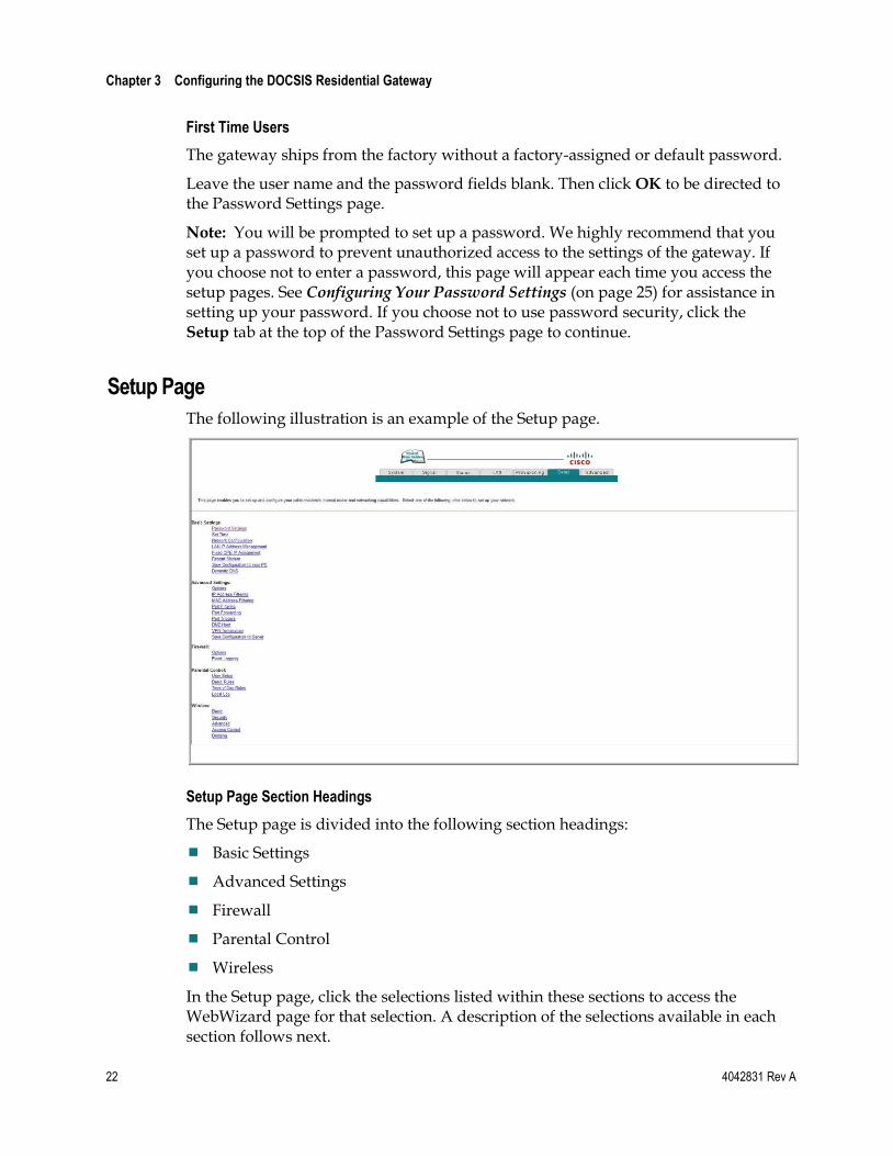
Setup Page
The following illustration is an example of the Setup page.
Setup Page Section Headings
The Setup page is divided into the following section headings:
Basic Settings
Advanced Settings
Firewall
Parental Control
Wireless
In the Setup page, click the selections listed within these sections to access the WebWizard page for that selection. A description of the selections available in each section follows next.
Configure Basic Settings
4042831 Rev A 23
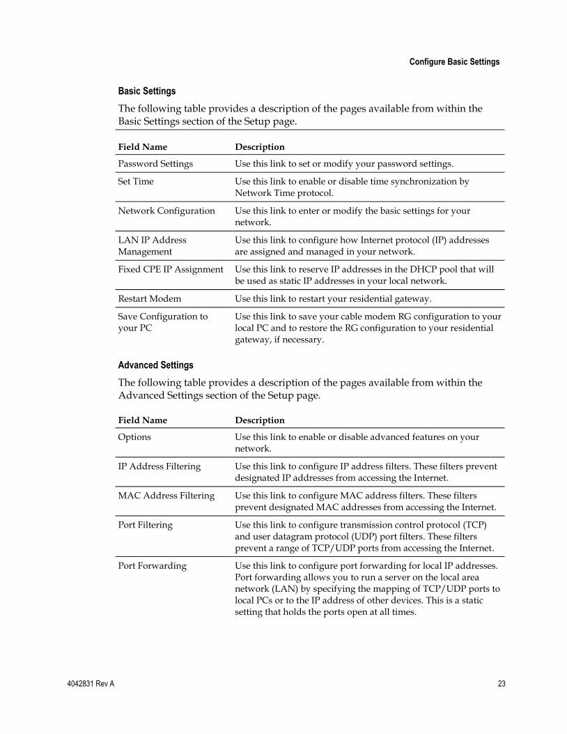
Basic Settings
The following table provides a description of the pages available from within the Basic Settings section of the Setup page.
Field Name Description
Password Settings Use this link to set or modify your password settings.
Set Time Use this link to enable or disable time synchronization by Network Time protocol.
Network Configuration Use this link to enter or modify the basic settings for your network.
LAN IP Address Management
Use this link to configure how Internet protocol (IP) addresses are assigned and managed in your network.
Fixed CPE IP Assignment Use this link to reserve IP addresses in the DHCP pool that will be used as static IP addresses in your local network.
Restart Modem Use this link to restart your residential gateway.
Save Configuration to your PC
Use this link to save your cable modem RG configuration to your local PC and to restore the RG configuration to your residential gateway, if necessary.
Advanced Settings
The following table provides a description of the pages available from within the Advanced Settings section of the Setup page.
Field Name Description
Options Use this link to enable or disable advanced features on your network.
IP Address Filtering Use this link to configure IP address filters. These filters prevent designated IP addresses from accessing the Internet.
MAC Address Filtering Use this link to configure MAC address filters. These filters prevent designated MAC addresses from accessing the Internet.
Port Filtering Use this link to configure transmission control protocol (TCP) and user datagram protocol (UDP) port filters. These filters prevent a range of TCP/UDP ports from accessing the Internet.
Port Forwarding Use this link to configure port forwarding for local IP addresses. Port forwarding allows you to run a server on the local area network (LAN) by specifying the mapping of TCP/UDP ports to local PCs or to the IP address of other devices. This is a static setting that holds the ports open at all times.
Chapter 3 Configuring the DOCSIS Residential Gateway
24 4042831 Rev A
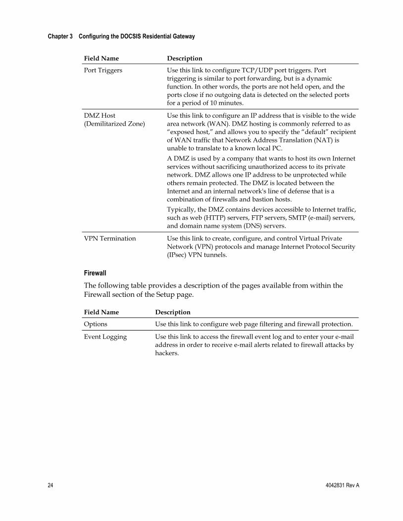
Field Name Description
Port Triggers Use this link to configure TCP/UDP port triggers. Port triggering is similar to port forwarding, but is a dynamic function. In other words, the ports are not held open, and the ports close if no outgoing data is detected on the selected ports for a period of 10 minutes.
DMZ Host (Demilitarized Zone)
Use this link to configure an IP address that is visible to the wide area network (WAN). DMZ hosting is commonly referred to as ―exposed host,‖ and allows you to specify the ―default‖ recipient of WAN traffic that Network Address Translation (NAT) is unable to translate to a known local PC.
A DMZ is used by a company that wants to host its own Internet services without sacrificing unauthorized access to its private network. DMZ allows one IP address to be unprotected while others remain protected. The DMZ is located between the Internet and an internal network's line of defense that is a combination of firewalls and bastion hosts.
Typically, the DMZ contains devices accessible to Internet traffic, such as web (HTTP) servers, FTP servers, SMTP (e-mail) servers, and domain name system (DNS) servers.
VPN Termination Use this link to create, configure, and control Virtual Private Network (VPN) protocols and manage Internet Protocol Security (IPsec) VPN tunnels.
Firewall
The following table provides a description of the pages available from within the Firewall section of the Setup page.
Field Name Description
Options Use this link to configure web page filtering and firewall protection.
Event Logging Use this link to access the firewall event log and to enter your e-mail address in order to receive e-mail alerts related to firewall attacks by hackers.
Configure Basic Settings
4042831 Rev A 25
Parental Control
The following table provides a description of the pages available from within the Parental Control section of the Setup page.
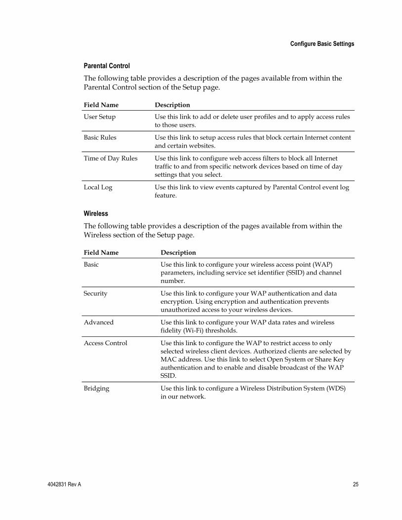
Field Name Description
User Setup Use this link to add or delete user profiles and to apply access rules to those users.
Basic Rules Use this link to setup access rules that block certain Internet content and certain websites.
Time of Day Rules Use this link to configure web access filters to block all Internet traffic to and from specific network devices based on time of day settings that you select.
Local Log Use this link to view events captured by Parental Control event log feature.
Wireless
The following table provides a description of the pages available from within the Wireless section of the Setup page.
Field Name Description
Basic Use this link to configure your wireless access point (WAP) parameters, including service set identifier (SSID) and channel number.
Security Use this link to configure your WAP authentication and data encryption. Using encryption and authentication prevents unauthorized access to your wireless devices.
Advanced Use this link to configure your WAP data rates and wireless fidelity (Wi-Fi) thresholds.
Access Control Use this link to configure the WAP to restrict access to only selected wireless client devices. Authorized clients are selected by MAC address. Use this link to select Open System or Share Key authentication and to enable and disable broadcast of the WAP SSID.
Bridging Use this link to configure a Wireless Distribution System (WDS) in our network.
Chapter 3 Configuring the DOCSIS Residential Gateway
26 4042831 Rev A
Configuring Your Password Settings
Use the Basic Settings - Password Settings page to set up or modify a password to restrict unauthorized persons from accessing to your residential gateway settings. Click Password Settings in the Basic Settings section of the Setup page to access the Password Settings page.
Notes:
Your gateway modem comes from the factory with no password enabled. We highly recommend that you set up a user password to prevent unauthorized users from modifying the settings of your network.
If you do choose to set up a password, use a password that you can easily remember. Do not forget your password.
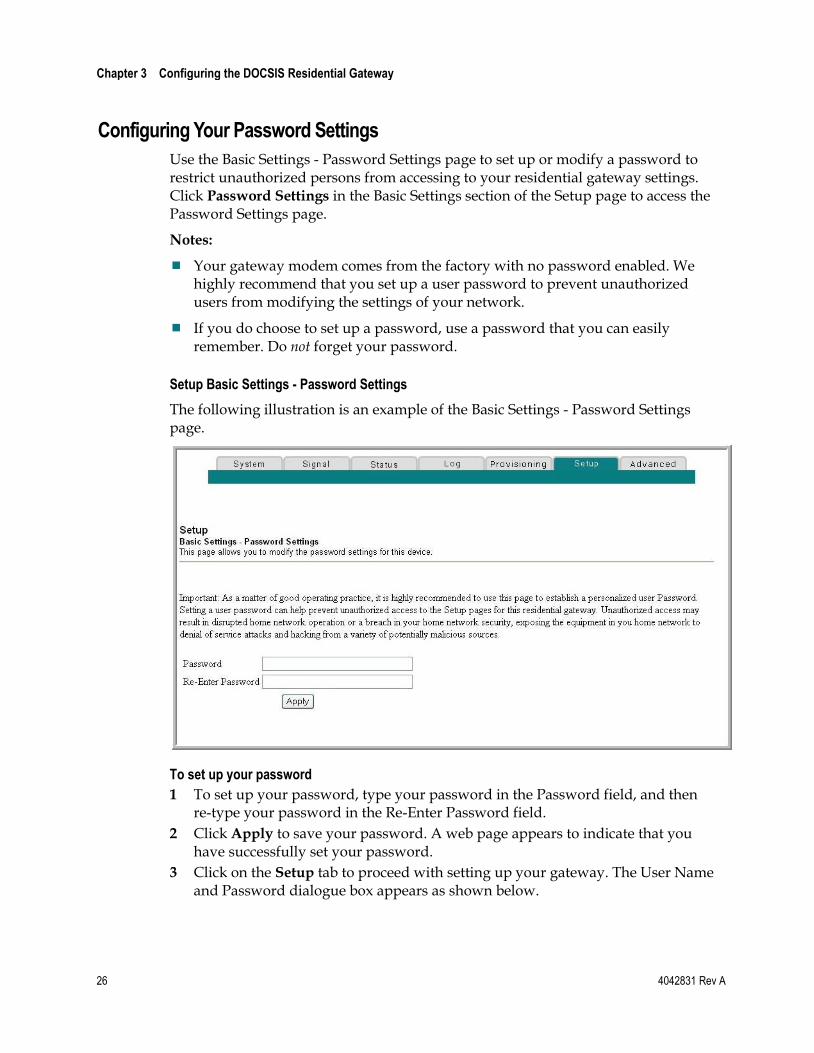
Setup Basic Settings - Password Settings
The following illustration is an example of the Basic Settings - Password Settings page.
To set up your password
1 To set up your password, type your password in the Password field, and then re-type your password in the Re-Enter Password field.
2 Click Apply to save your password. A web page appears to indicate that you have successfully set your password.
3 Click on the Setup tab to proceed with setting up your gateway. The User Name and Password dialogue box appears as shown below.
Configure Basic Settings
4042831 Rev A 27
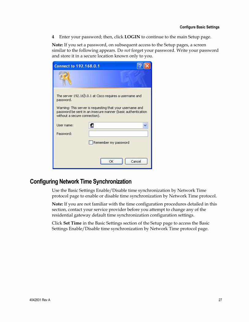
4 Enter your password; then, click LOGIN to continue to the main Setup page.
Note: If you set a password, on subsequent access to the Setup pages, a screen similar to the following appears. Do not forget your password. Write your password and store it in a secure location known only to you.
Configuring Network Time Synchronization
Use the Basic Settings Enable/Disable time synchronization by Network Time protocol page to enable or disable time synchronization by Network Time protocol.
Note: If you are not familiar with the time configuration procedures detailed in this section, contact your service provider before you attempt to change any of the residential gateway default time synchronization configuration settings.
Click Set Time in the Basic Settings section of the Setup page to access the Basic Settings Enable/Disable time synchronization by Network Time protocol page.
Chapter 3 Configuring the DOCSIS Residential Gateway
28 4042831 Rev A
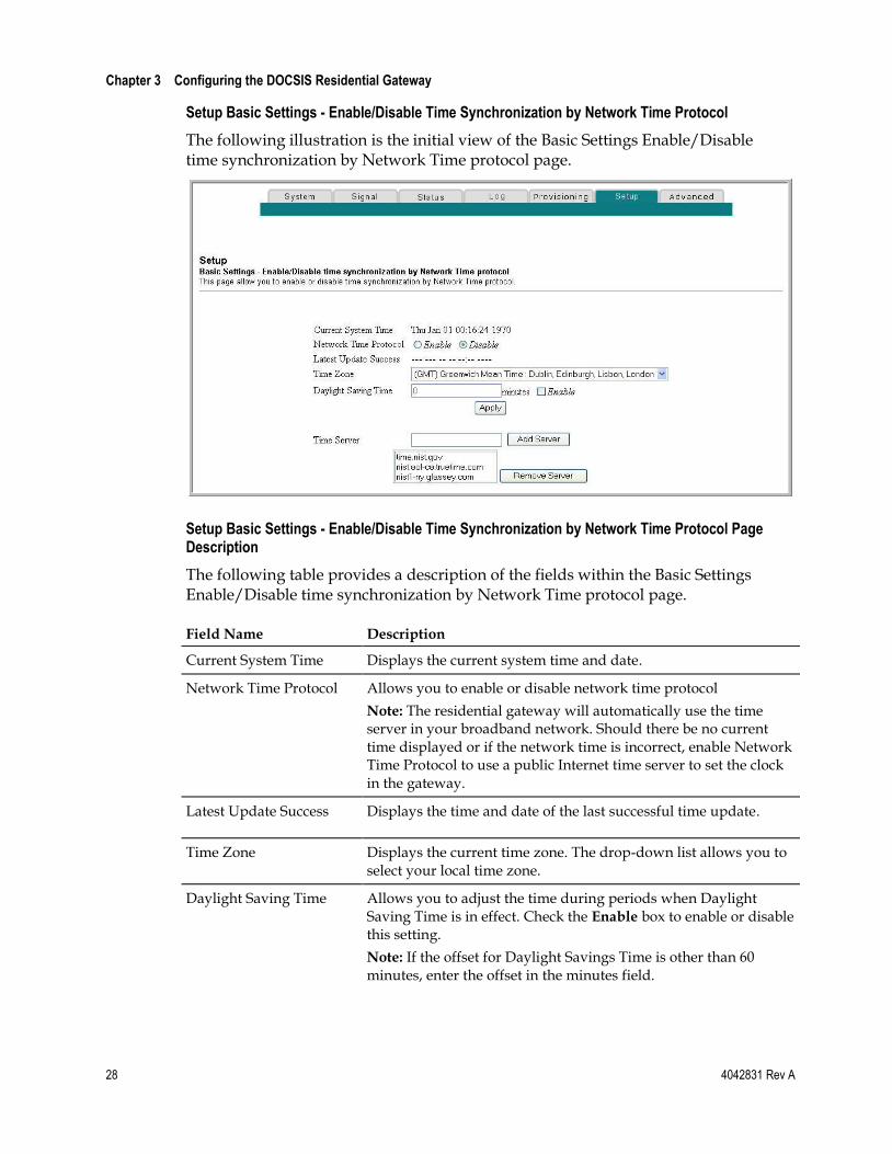
Setup Basic Settings - Enable/Disable Time Synchronization by Network Time Protocol
The following illustration is the initial view of the Basic Settings Enable/Disable time synchronization by Network Time protocol page.
Setup Basic Settings - Enable/Disable Time Synchronization by Network Time Protocol Page Description
The following table provides a description of the fields within the Basic Settings Enable/Disable time synchronization by Network Time protocol page.
Field Name Description
Current System Time Displays the current system time and date.
Network Time Protocol Allows you to enable or disable network time protocol
Note: The residential gateway will automatically use the time server in your broadband network. Should there be no current time displayed or if the network time is incorrect, enable Network Time Protocol to use a public Internet time server to set the clock in the gateway.
Latest Update Success Displays the time and date of the last successful time update.
Time Zone Displays the current time zone. The drop-down list allows you to select your local time zone.
Daylight Saving Time Allows you to adjust the time during periods when Daylight Saving Time is in effect. Check the Enable box to enable or disable this setting.
Note: If the offset for Daylight Savings Time is other than 60 minutes, enter the offset in the minutes field.
Configure Basic Settings
4042831 Rev A 29
Field Name Description
Time Server Add and delete time server URLs or IP addresses to and from the list, as required. When using Network Time Protocol, multiple time servers can be specified for the gateway to query for time of day. The gateway will sequentially step through the listed time servers until it acquires the current time. There are three well known public time servers entered as default servers.
Function Keys
Key Description
Apply Saves all additions, edits, and changes.
Add Server Allows you to add a network time server.
Remove Server Allows you to remove a network time server.
Under normal conditions, you should use the default network settings. In the event that the network time does not match your local time, or, if your system requires different settings to operate correctly, you can change the default network settings using the Setup Basic Settings - Network Configuration page.
Configuring the Network Settings
Note: If you are not familiar with the network configuration procedures detailed in the following sections, contact your service provider before you attempt to change any of the residential gateway default network configuration settings.
Click Network Configuration in the Basic Settings section of the Setup page to access the Setup Basic Settings - Network Configuration page.
Chapter 3 Configuring the DOCSIS Residential Gateway
30 4042831 Rev A
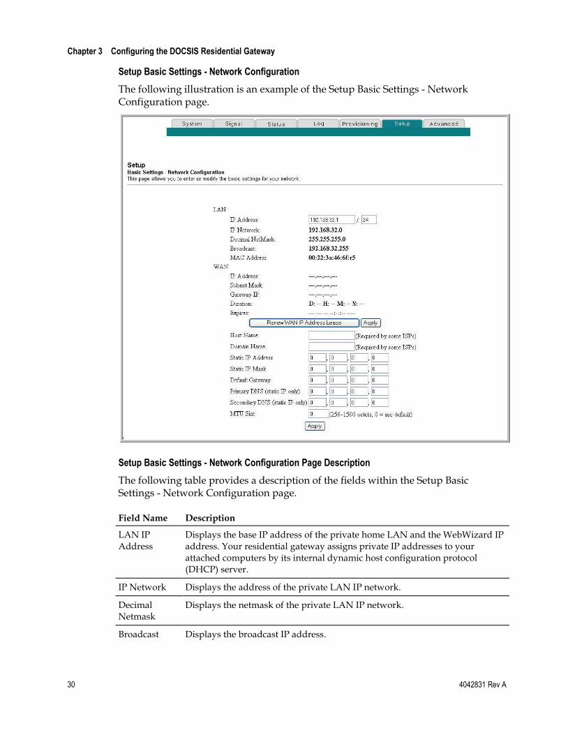
Setup Basic Settings - Network Configuration
The following illustration is an example of the Setup Basic Settings - Network Configuration page.
Setup Basic Settings - Network Configuration Page Description
The following table provides a description of the fields within the Setup Basic Settings - Network Configuration page.
Field Name Description
LAN IP Address
Displays the base IP address of the private home LAN and the WebWizard IP address. Your residential gateway assigns private IP addresses to your attached computers by its internal dynamic host configuration protocol (DHCP) server.
IP Network Displays the address of the private LAN IP network.
Decimal Netmask
Displays the netmask of the private LAN IP network.
Broadcast Displays the broadcast IP address.
Configure Basic Settings
4042831 Rev A 31
Field Name Description
MAC Address Displays the MAC address for the WAN. The factory assigned MAC address for the WAN is also referred to as the WAN MGT MAC.
WAN IP Address
Displays the public IP address assigned to your gateway by your ISP. The WAN port will be assigned a public IP address automatically by your ISP except when a static IP address is set up as described below. The WAN IP address will be shared by all the PCs in your private local area network to access the Internet.
Subnet Mask Displays the subnet mask for your WAN port. This address is automatically assigned to your WAN port by your ISP except when a static IP address is set up as described later in this table.
Gateway IP Displays a Gateway IP address for your WAN port. This address is automatically assigned to your WAN port by your ISP except when a static IP address is set up as described later in this table.
Duration Displays the length of time your WAN IP address is valid.
Expires Displays the date and time your WAN IP address expires.
Host Name Displays the host name that is usually downloaded to your gateway by your ISP. However, some ISPs require this information to be entered manually. If manual entry is required, your ISP will provide the information for you to enter into this field.
Domain Name Displays the domain name that is usually downloaded to your gateway by your ISP. However, some ISPs require this information to be entered manually. If manual entry is required, your ISP will provide the information for you to enter into this field.
Static IP Address
Manual entry is required. Your ISP will provide the information for you to enter into this field.
Note: When setting a static IP address, you must enter the IP address, subnet mask, and default gateway before the static IP address will become operational.
Static IP Mask Manual entry is required. Your ISP will provide the information for you to enter into this field.
Default Gateway
Manual entry is required. Your ISP will provide the information for you to enter into this field.
Primary DNS (static IP only)
Manual entry is required. Your ISP will provide the information for you to enter into this field.
Chapter 3 Configuring the DOCSIS Residential Gateway
32 4042831 Rev A
Field Name Description
Secondary DNS (static IP only)
Manual entry is required. Your ISP will provide the information for you to enter into this field.
MTU Size Sets the size of the maximum transmission unit (MTU) for the network interface. The default value is 0 (zero)
Important: Do not change this value unless you are an experienced user.
Function Keys
The following function keys appear on the Setup Basic Settings - Network Configuration page.
Key Description
Renew WAN IP Address Lease
Forces a release and renewal of your WAN IP address.
Apply Saves the values you enter into the fields without closing the screen.
Configuring and Managing IP Addresses
Use the Setup Basic Settings - IP Management page to configure how your system manages and assigns IP addresses in your network.
Note: If you are not familiar with the IP management procedures detailed in this section, contact your service provider before you attempt to change any of the residential gateway default IP management settings.
Click LAN IP Address Management in the Basic Settings section of the Setup page to access the Setup Basic Settings - IP Management page.
Configure Basic Settings
4042831 Rev A 33
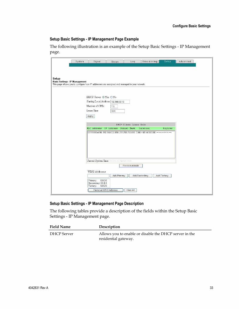
Setup Basic Settings - IP Management Page Example
The following illustration is an example of the Setup Basic Settings - IP Management page.
Setup Basic Settings - IP Management Page Description
The following tables provide a description of the fields within the Setup Basic Settings - IP Management page.
Field Name Description
DHCP Server Allows you to enable or disable the DHCP server in the residential gateway.
Chapter 3 Configuring the DOCSIS Residential Gateway
34 4042831 Rev A
Field Name Description
Starting Local Address Displays the starting address used by the built-in DHCP server to distribute Private LAN IP addresses. In the example shown, addresses between 2 and 9 can be used for devices on your Private LAN that require fixed IP addresses such as printers or a device assigned as a DMZ host.
Note: The LAN IP address ending in 1 is reserved for the internal gateway server. The LAN IP address ending in 255 is also reserved and should not be used for CPE devices.
Number of CPEs Enter the maximum number of devices allowed to connect to the Private LAN.
Notes:
The Factory Default is 245. The maximum number of devices is 253. This is the combined total of addresses reserved for static IP addresses, for example, the sum of the IP addresses between 2 and the value entered in the Starting Local Address field and the value entered in the Number of CPEs field.
The sum of the value entered in the Starting Local Address field and the value entered in the Number of CPEs field must always be 255 or less.
DHCP Client Lease Info Displays the MAC address, IP Address, Subnet Mask, Duration and Expiration date of all devices issued an IP address by the built-in DHCP server. This field also displays the current system time and date.
WINS Addresses Allows you to manually enter Windows Internet Name Server (WINS) server addresses.
Function Keys
The following function keys appear on the Basic Settings - IP Management page.
Key Description
Apply Saves the values you enter into the fields without closing the screen.
Force Available Forces the release of an IP address for you to re-use.
Add Primary Saves the WINS address for one server.
Add Secondary Saves the WINS address for a second server.
Add Tertiary Saves the WINS address for a third server.
Remove WINS Address Removes the WINS address selected.
Clear All Removes all defined WINS addresses.
Configure Basic Settings
4042831 Rev A 35
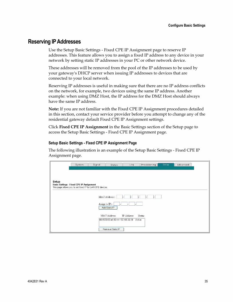
Reserving IP Addresses
Use the Setup Basic Settings - Fixed CPE IP Assignment page to reserve IP addresses. This feature allows you to assign a fixed IP address to any device in your network by setting static IP addresses in your PC or other network device.
These addresses will be removed from the pool of the IP addresses to be used by your gateway's DHCP server when issuing IP addresses to devices that are connected to your local network.
Reserving IP addresses is useful in making sure that there are no IP address conflicts on the network, for example, two devices using the same IP address. Another example: when using DMZ Host, the IP address for the DMZ Host should always have the same IP address.
Note: If you are not familiar with the Fixed CPE IP Assignment procedures detailed in this section, contact your service provider before you attempt to change any of the residential gateway default Fixed CPE IP Assignment settings.
Click Fixed CPE IP Assignment in the Basic Settings section of the Setup page to access the Setup Basic Settings - Fixed CPE IP Assignment page.
Setup Basic Settings - Fixed CPE IP Assignment Page
The following illustration is an example of the Setup Basic Settings - Fixed CPE IP Assignment page.
Chapter 3 Configuring the DOCSIS Residential Gateway
36 4042831 Rev A
Setup Basic Settings - Fixed CPE IP Assignment Page Description
The following tables provide a description of the fields within the Setup Basic Settings - Fixed CPE IP Assignment page.
Field Name Description
MAC Address The MAC address of the PC or device (for example, a printer) for which you want to reserve a specific IP address on the network.
Assign to IP The IP address you assign to the PC or device for which you want to reserve a specific IP address on the network. Only MAC addresses within the range of the gateway's DHCP address pool can be reserved with this feature.
Note: The factory configuration of your gateway sets aside IP addresses 192.168.0.2 through 192.168.0.9 for static IP addresses.
Function Keys
Key Description
Add Static IP Adds the Static IP address to the list of assigned IP addresses.
Remove Static IP Removes the Static IP address from the list of assigned IP addresses.
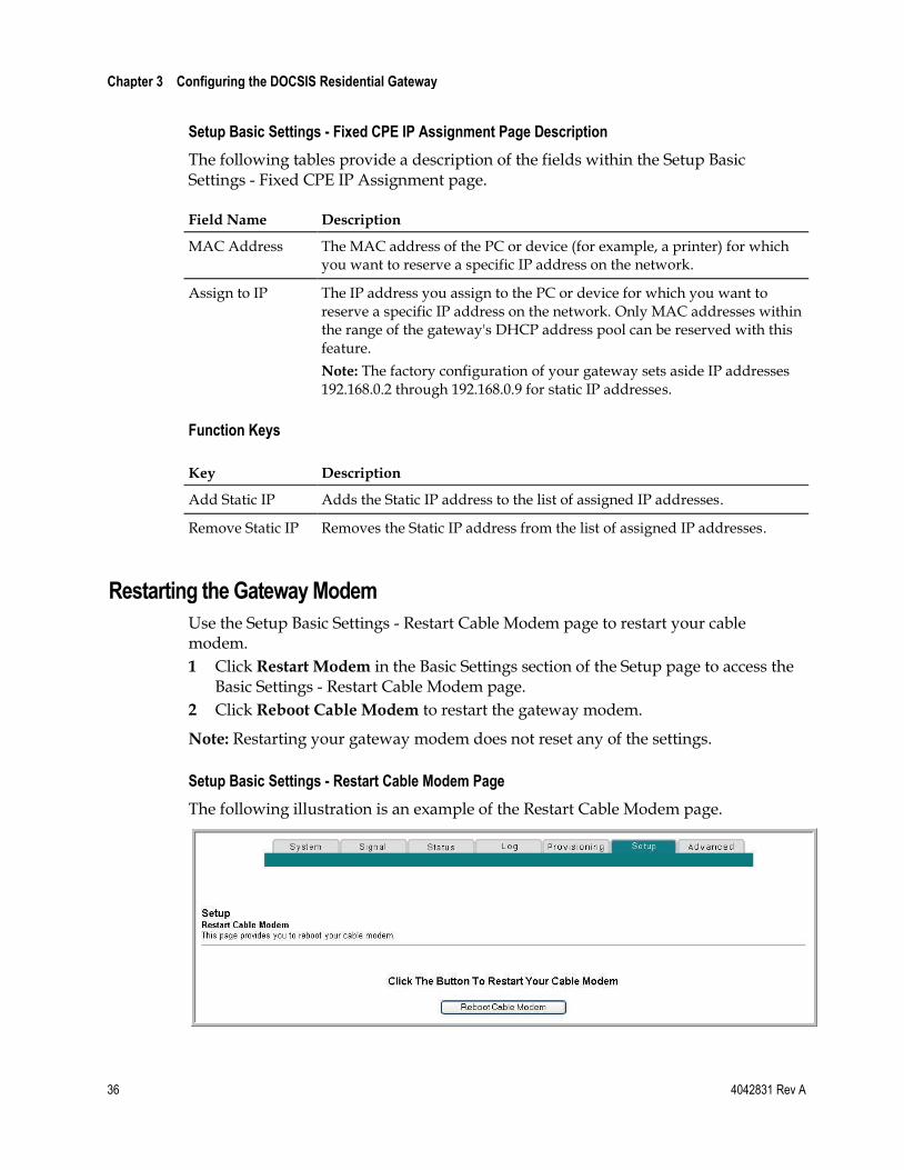
Restarting the Gateway Modem
Use the Setup Basic Settings - Restart Cable Modem page to restart your cable modem.
1 Click Restart Modem in the Basic Settings section of the Setup page to access the Basic Settings - Restart Cable Modem page.
2 Click Reboot Cable Modem to restart the gateway modem.
Note: Restarting your gateway modem does not reset any of the settings.
Setup Basic Settings - Restart Cable Modem Page
The following illustration is an example of the Restart Cable Modem page.
Configure Basic Settings
4042831 Rev A 37
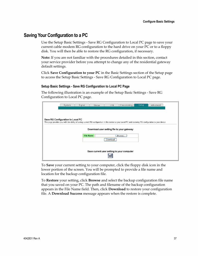
Saving Your Configuration to a PC
Use the Setup Basic Settings - Save RG Configuration to Local PC page to save your current cable modem RG configuration to the hard drive on your PC or to a floppy disk. You will then be able to restore the RG configuration, if necessary.
Note: If you are not familiar with the procedures detailed in this section, contact your service provider before you attempt to change any of the residential gateway default settings.
Click Save Configuration to your PC in the Basic Settings section of the Setup page to access the Setup Basic Settings - Save RG Configuration to Local PC page.
Setup Basic Settings - Save RG Configuration to Local PC Page
The following illustration is an example of the Setup Basic Settings - Save RG Configuration to Local PC page.
To Save your current setting to your computer, click the floppy disk icon in the lower portion of the screen. You will be prompted to provide a file name and location for the backup configuration file.
To Restore your setting, click Browse and select the backup configuration file name that you saved on your PC. The path and filename of the backup configuration appears in the File Name field. Then, click Download to restore your configuration file. A Download Success message appears when the restore is complete.
Chapter 3 Configuring the DOCSIS Residential Gateway
38 4042831 Rev A
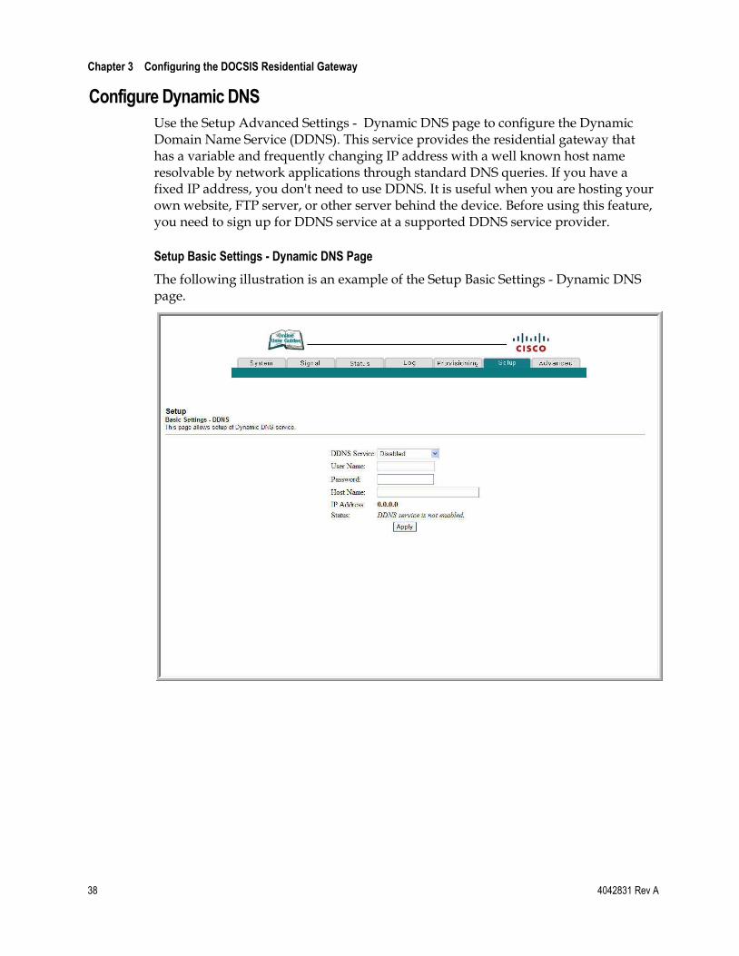
Configure Dynamic DNS
Use the Setup Advanced Settings - Dynamic DNS page to configure the Dynamic Domain Name Service (DDNS). This service provides the residential gateway that has a variable and frequently changing IP address with a well known host name resolvable by network applications through standard DNS queries. If you have a fixed IP address, you don't need to use DDNS. It is useful when you are hosting your own website, FTP server, or other server behind the device. Before using this feature, you need to sign up for DDNS service at a supported DDNS service provider.
Setup Basic Settings - Dynamic DNS Page
The following illustration is an example of the Setup Basic Settings - Dynamic DNS page.
Configure Basic Settings
4042831 Rev A 39
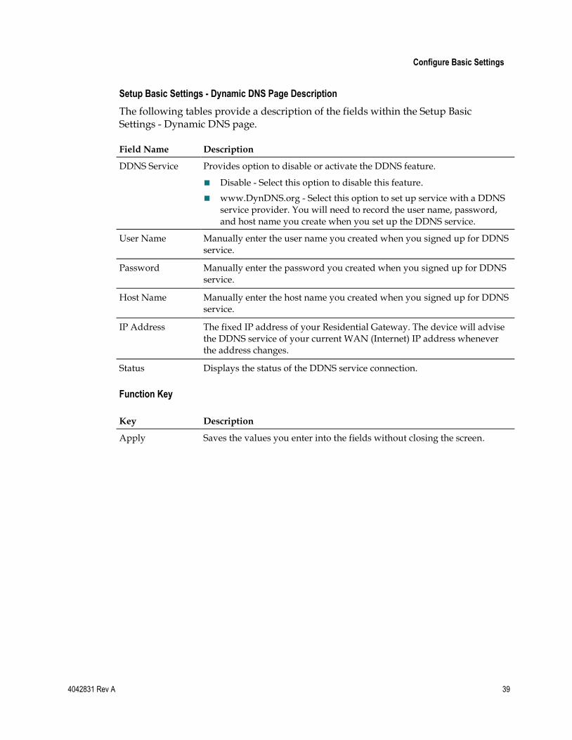
Setup Basic Settings - Dynamic DNS Page Description
The following tables provide a description of the fields within the Setup Basic Settings - Dynamic DNS page.
Field Name Description
DDNS Service Provides option to disable or activate the DDNS feature.
Disable - Select this option to disable this feature.
www.DynDNS.org - Select this option to set up service with a DDNS service provider. You will need to record the user name, password, and host name you create when you set up the DDNS service.
User Name Manually enter the user name you created when you signed up for DDNS service.
Password Manually enter the password you created when you signed up for DDNS service.
Host Name Manually enter the host name you created when you signed up for DDNS service.
IP Address The fixed IP address of your Residential Gateway. The device will advise the DDNS service of your current WAN (Internet) IP address whenever the address changes.
Status Displays the status of the DDNS service connection.
Function Key
Key Description
Apply Saves the values you enter into the fields without closing the screen.
Chapter 3 Configuring the DOCSIS Residential Gateway
40 4042831 Rev A
Configure Advanced Settings This section describes how to configure Advanced settings for the residential gateway.
Enabling and Disabling Advanced Features
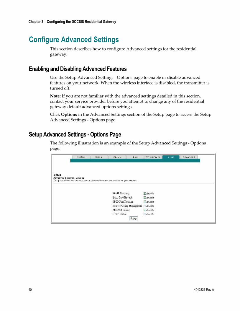
Use the Setup Advanced Settings - Options page to enable or disable advanced features on your network. When the wireless interface is disabled, the transmitter is turned off.
Note: If you are not familiar with the advanced settings detailed in this section, contact your service provider before you attempt to change any of the residential gateway default advanced options settings.
Click Options in the Advanced Settings section of the Setup page to access the Setup Advanced Settings - Options page.
Setup Advanced Settings - Options Page
The following illustration is an example of the Setup Advanced Settings - Options page.
Configure Advanced Settings
4042831 Rev A 41
Setup Advanced Settings - Options Page Description
The following table provides a description of the fields within the Setup Advanced Settings - Options page.
Note: If you make changes in the Setup Advanced Settings - Options page, click Apply to apply and save your new IP address filter settings.
Field Name Description
WAN Blocking Checking this box prevents the residential gateway from being visible to the WAN. For example, pings to the WAN IP address are not returned.
IPsec PassThrough Checking this box allows applications that use IPsec (IP Security) to pass through the firewall.
PPTP PassThrough Checking this box allows applications that use Point to Point Tunneling Protocol (PPTP) to pass through the firewall.
Remote Config Management
Checking this box enables Remote Configuration Management that allows the user or network operator to view and/or modify the gateway set-up parameters from a location on the WAN, as opposed to the LAN side of the gateway. Access to the set-up parameters is obtained by using the password to access the WebWizard.
Enable this feature by checking the Remote Config Management box on the Setup Advanced Settings - Options page. To access your gateway from a remote location, you must also know the WAN IP address of the gateway. To find the WAN IP address, go to the Network Configuration page under Basic Settings. You will find the gateway's WAN IP address list on this page.
Enter the WAN IP address of your gateway into the address field of any web browser using the following format: http://xxx.xxx.xxx.xxx:8080 where xxx.xxx.xxx.xxx represents the WAN IP address of your gateway.
Be sure to follow the syntax exactly, and then click Go or press Enter. Your gateway web pages will appear on the remote computer. You will still need to enter your password to access the Setup pages of your gateway
Note: If you choose to enable (check) this feature, be sure to set up a user password to prevent unauthorized access to your gateway settings.
Multicast Enable Checking this box allows multicasts to pass from the WAN side through to the private network.
UPnP Enable Checking this box enables Universal Plug and Play features.
Chapter 3 Configuring the DOCSIS Residential Gateway
42 4042831 Rev A
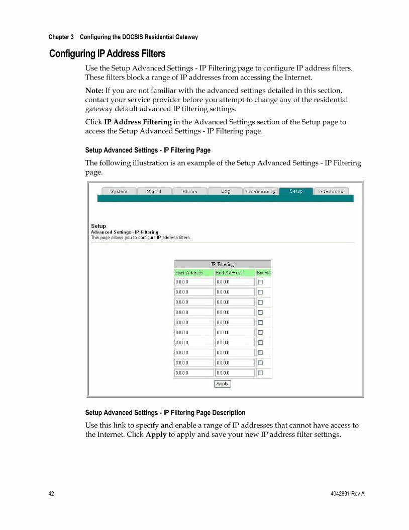
Configuring IP Address Filters
Use the Setup Advanced Settings - IP Filtering page to configure IP address filters. These filters block a range of IP addresses from accessing the Internet.
Note: If you are not familiar with the advanced settings detailed in this section, contact your service provider before you attempt to change any of the residential gateway default advanced IP filtering settings.
Click IP Address Filtering in the Advanced Settings section of the Setup page to access the Setup Advanced Settings - IP Filtering page.
Setup Advanced Settings - IP Filtering Page
The following illustration is an example of the Setup Advanced Settings - IP Filtering page.
Setup Advanced Settings - IP Filtering Page Description
Use this link to specify and enable a range of IP addresses that cannot have access to the Internet. Click Apply to apply and save your new IP address filter settings.
Configure Advanced Settings
4042831 Rev A 43
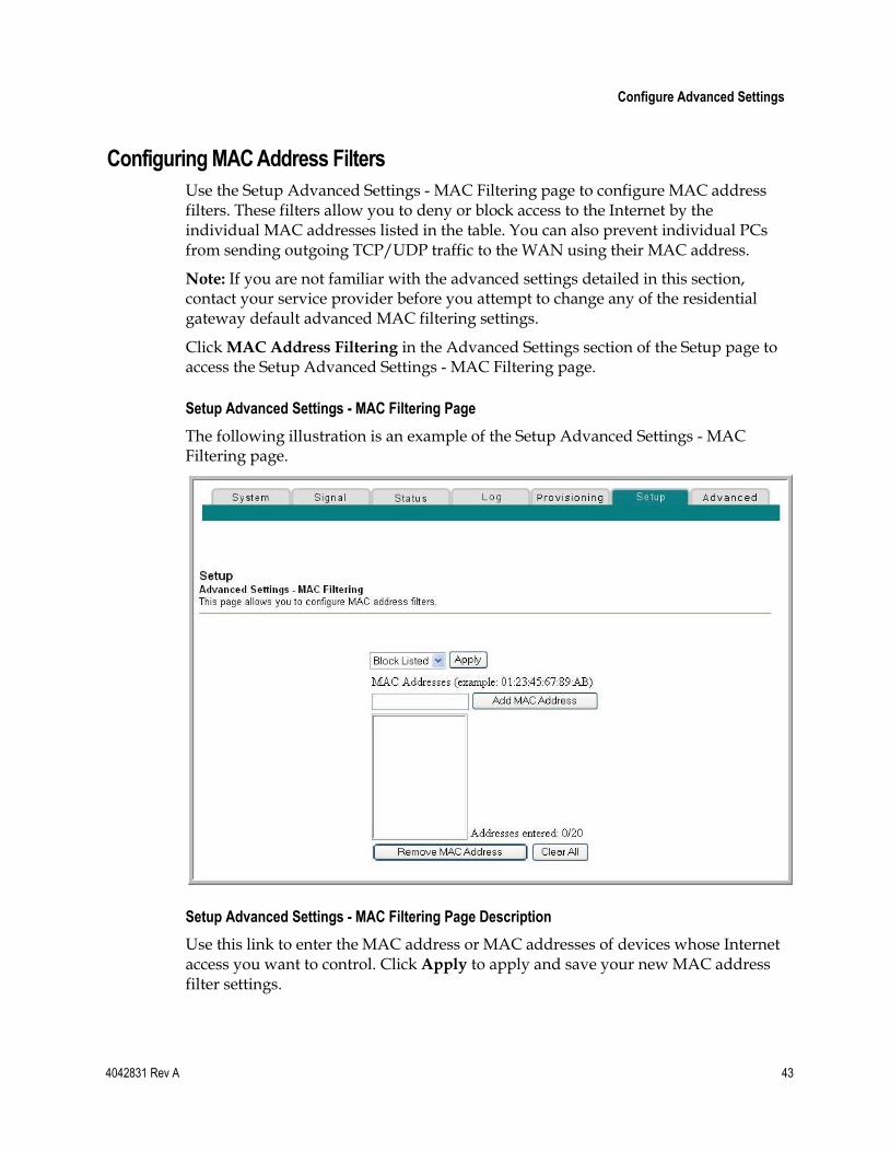
Configuring MAC Address Filters
Use the Setup Advanced Settings - MAC Filtering page to configure MAC address filters. These filters allow you to deny or block access to the Internet by the individual MAC addresses listed in the table. You can also prevent individual PCs from sending outgoing TCP/UDP traffic to the WAN using their MAC address.
Note: If you are not familiar with the advanced settings detailed in this section, contact your service provider before you attempt to change any of the residential gateway default advanced MAC filtering settings.
Click MAC Address Filtering in the Advanced Settings section of the Setup page to access the Setup Advanced Settings - MAC Filtering page.
Setup Advanced Settings - MAC Filtering Page
The following illustration is an example of the Setup Advanced Settings - MAC Filtering page.
Setup Advanced Settings - MAC Filtering Page Description
Use this link to enter the MAC address or MAC addresses of devices whose Internet access you want to control. Click Apply to apply and save your new MAC address filter settings.
Chapter 3 Configuring the DOCSIS Residential Gateway
44 4042831 Rev A
Setting Up MAC Address Filters
The Block/Pass drop down menu allows you to block or pass Internet access to the MAC addresses of the devices you list in the MAC Address Filters table. The following table describes the function of the Block/Pass drop down menu.
Field Name Description
Block Listed (Default) Select Block to deny Internet access to the MAC addresses of the devices you list in the table. All other MAC addresses will be allowed Internet access.
Pass Select Pass to allow Internet access only to the MAC addresses of the devices you list in the table. Any MAC addresses not listed in the table will be denied Internet access.
Function Keys
The following function keys appear on the Advanced Settings - MAC Filtering page.
Key Description
Apply Saves the values you enter into the fields without closing the screen.
Add MAC Address Saves the MAC Address entered in the associated text field.
Remove MAC Address Removes the selected MAC address.
Clear All Removes all defined MAC addresses .
Configuring and Enabling TCP and UDP Port Filters
Use the Setup Advanced Settings - Port Filtering page to configure and enable TCP and UDP port filters. These filters prevent a range of TCP/UDP ports from accessing the Internet. You can also prevent PCs from sending outgoing TCP/UDP traffic to the WAN on specific IP port numbers. This filter is not IP address- or MAC address-specific. The system blocks the specified port ranges for all PCs.
Note: If you are not familiar with the advanced settings detailed in this section, contact your service provider before you attempt to change any of the residential gateway default advanced port filtering settings.
Click Port Filtering in the Advanced Settings section of the Setup page to access the Setup Advanced Settings - Port Filtering page.
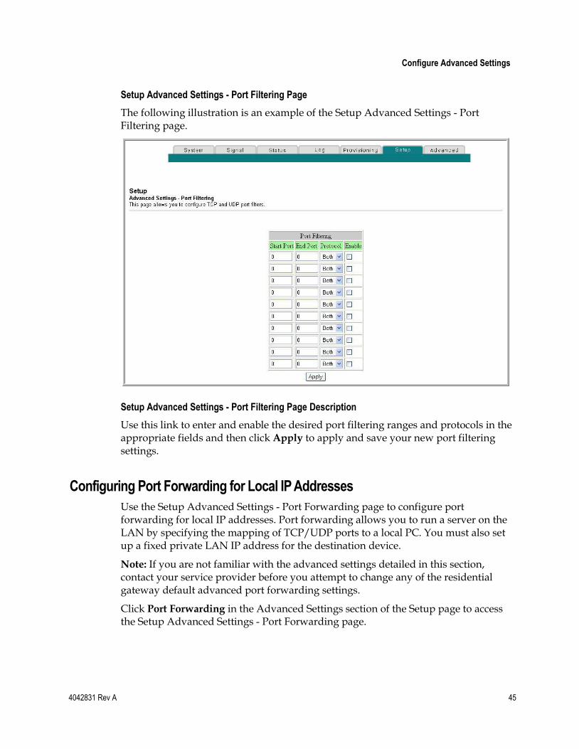
Configure Advanced Settings
4042831 Rev A 45
Setup Advanced Settings - Port Filtering Page
The following illustration is an example of the Setup Advanced Settings - Port Filtering page.
Setup Advanced Settings - Port Filtering Page Description
Use this link to enter and enable the desired port filtering ranges and protocols in the appropriate fields and then click Apply to apply and save your new port filtering settings.
Configuring Port Forwarding for Local IP Addresses
Use the Setup Advanced Settings - Port Forwarding page to configure port forwarding for local IP addresses. Port forwarding allows you to run a server on the LAN by specifying the mapping of TCP/UDP ports to a local PC. You must also set up a fixed private LAN IP address for the destination device.
Note: If you are not familiar with the advanced settings detailed in this section, contact your service provider before you attempt to change any of the residential gateway default advanced port forwarding settings.
Click Port Forwarding in the Advanced Settings section of the Setup page to access the Setup Advanced Settings - Port Forwarding page.
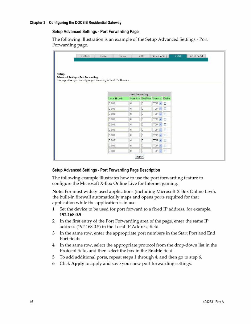
Chapter 3 Configuring the DOCSIS Residential Gateway
46 4042831 Rev A
Setup Advanced Settings - Port Forwarding Page
The following illustration is an example of the Setup Advanced Settings - Port Forwarding page.
Setup Advanced Settings - Port Forwarding Page Description
The following example illustrates how to use the port forwarding feature to configure the Microsoft X-Box Online Live for Internet gaming.
Note: For most widely used applications (including Microsoft X-Box Online Live), the built-in firewall automatically maps and opens ports required for that application while the application is in use.
1 Set the device to be used for port forward to a fixed IP address, for example, 192.168.0.5.
2 In the first entry of the Port Forwarding area of the page, enter the same IP address (192.168.0.5) in the Local IP Address field.
3 In the same row, enter the appropriate port numbers in the Start Port and End Port fields.
4 In the same row, select the appropriate protocol from the drop-down list in the Protocol field, and then select the box in the Enable field.
5 To add additional ports, repeat steps 1 through 4, and then go to step 6.
6 Click Apply to apply and save your new port forwarding settings.
Configure Advanced Settings
4042831 Rev A 47
Configuring TCP/UDP Port Triggers
Use the Setup Advanced Settings - Port Triggers page to configure TCP/UDP port triggers. Port triggering is similar to port forwarding but is dynamic. In other words, the system does not hold the ports open indefinitely. For example, when the residential gateway detects outgoing data on a specific IP port number set in the ―Trigger Range,‖ the resulting ports set in the ―Target Range‖ will open for incoming data. If the system detects no outgoing traffic on the ―Trigger Range‖ ports for a period of 10 minutes, the ―Target Range‖ ports close. This is a safer method for opening specific ports for special applications, such as, video conferencing programs, interactive gaming, and file transfer in chat programs. This is safe because the ports are dynamically triggered and not held open continuously or left open erroneously by the router administrator. Therefore, these ports are not exposed and vulnerable for potential hackers to discover.
Note: If you are not familiar with the advanced settings detailed in this section, contact your service provider before you attempt to change any of the residential gateway default advanced port triggers settings.
Click Port Triggers in the Advanced Settings section of the Setup page to access the Setup Advanced Settings - Port Triggers page.
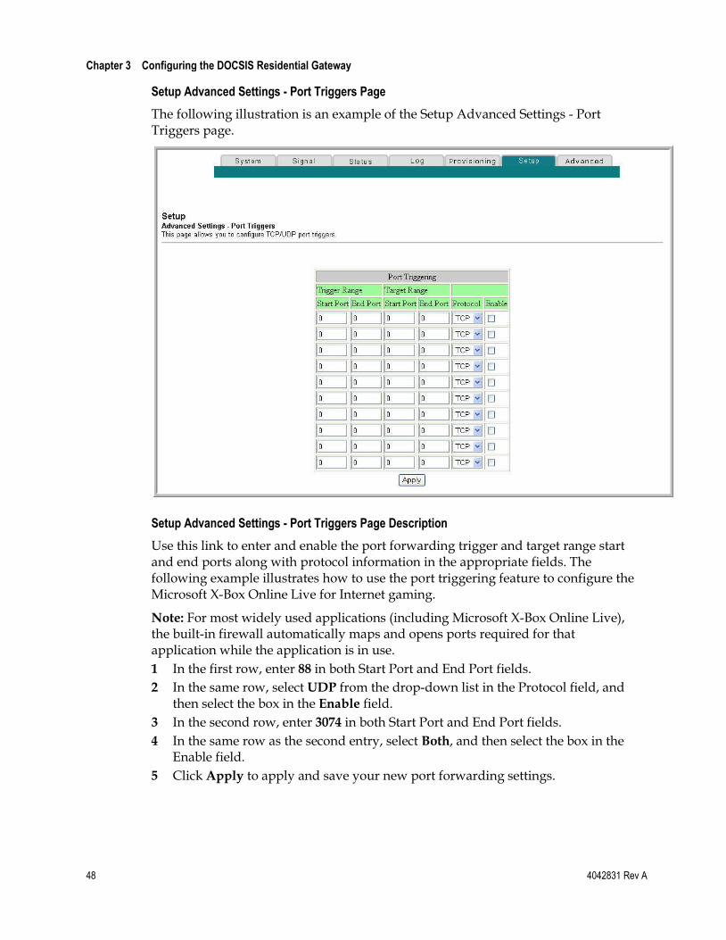
Chapter 3 Configuring the DOCSIS Residential Gateway
48 4042831 Rev A
Setup Advanced Settings - Port Triggers Page
The following illustration is an example of the Setup Advanced Settings - Port Triggers page.
Setup Advanced Settings - Port Triggers Page Description
Use this link to enter and enable the port forwarding trigger and target range start and end ports along with protocol information in the appropriate fields. The following example illustrates how to use the port triggering feature to configure the Microsoft X-Box Online Live for Internet gaming.
Note: For most widely used applications (including Microsoft X-Box Online Live), the built-in firewall automatically maps and opens ports required for that application while the application is in use.
1 In the first row, enter 88 in both Start Port and End Port fields.
2 In the same row, select UDP from the drop-down list in the Protocol field, and then select the box in the Enable field.
3 In the second row, enter 3074 in both Start Port and End Port fields.
4 In the same row as the second entry, select Both, and then select the box in the Enable field.
5 Click Apply to apply and save your new port forwarding settings.
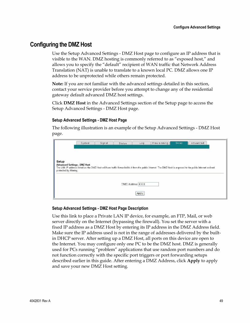
Configure Advanced Settings
4042831 Rev A 49
Configuring the DMZ Host
Use the Setup Advanced Settings - DMZ Host page to configure an IP address that is visible to the WAN. DMZ hosting is commonly referred to as ―exposed host,‖ and allows you to specify the ―default‖ recipient of WAN traffic that Network Address Translation (NAT) is unable to translate to a known local PC. DMZ allows one IP address to be unprotected while others remain protected.
Note: If you are not familiar with the advanced settings detailed in this section, contact your service provider before you attempt to change any of the residential gateway default advanced DMZ host settings.
Click DMZ Host in the Advanced Settings section of the Setup page to access the Setup Advanced Settings - DMZ Host page.
Setup Advanced Settings - DMZ Host Page
The following illustration is an example of the Setup Advanced Settings - DMZ Host page.
Setup Advanced Settings - DMZ Host Page Description
Use this link to place a Private LAN IP device, for example, an FTP, Mail, or web server directly on the Internet (bypassing the firewall). You set the server with a fixed IP address as a DMZ Host by entering its IP address in the DMZ Address field. Make sure the IP address used is not in the range of addresses delivered by the built-in DHCP server. After setting up a DMZ Host, all ports on this device are open to the Internet. You may configure only one PC to be the DMZ host. DMZ is generally used for PCs running ―problem‖ applications that use random port numbers and do not function correctly with the specific port triggers or port forwarding setups described earlier in this guide. After entering a DMZ Address, click Apply to apply and save your new DMZ Host setting.

Chapter 3 Configuring the DOCSIS Residential Gateway
50 4042831 Rev A
Configuring VPN Termination
Use the Setup Advanced Settings - VPN Termination page to configure VPN protocols and manage VPN tunnels. A VPN is a connection between two endpoints in different networks that allows private data to be sent securely and transparently over public networks or other private networks. With a VPN, you can send data securely between these two locations or networks. This is accomplished by creating a "VPN tunnel." A VPN tunnel connects the two PCs or networks and allows data to be transmitted over the Internet as if it were still within those networks. The VPN tunnel uses IPsec (Internet Protocol security) to encrypt the data sent between the two networks and encapsulate the data within a normal Ethernet/IP frame so as to transport the private network securely and seamlessly through other public or private networks.
A VPN provides a cost-effective and more secure alternative to using a private, dedicated, leased line for a private network. Using industry standard encryption and authentication techniques, an Internet Protocol Security (IPsec) VPN creates a secure connection that operates as if you were directly connected to your local network.
For example, a VPN allows users to sit at home and connect to his/her employer's corporate network and receive an IP address in their private network just as though they were sitting in their office connected to their corporate LAN.
Another advantage of a VPN network is that it all proprietary Microsoft Windows-based networking protocols can pass through the router using the VPN tunnel to access corporate shared network drives.
Note: If you are not familiar with the advanced settings detailed in this section, contact your service provider before you attempt to change any of the wireless home gateway defaults advanced VPN Termination settings.
Click VPN Termination in the Advanced Settings section of the Setup page to access the Setup Advanced Settings - VPN Termination - Status page. The VPN Termination - Status page allows you to create, configure, and control IPsec VPN tunnels.
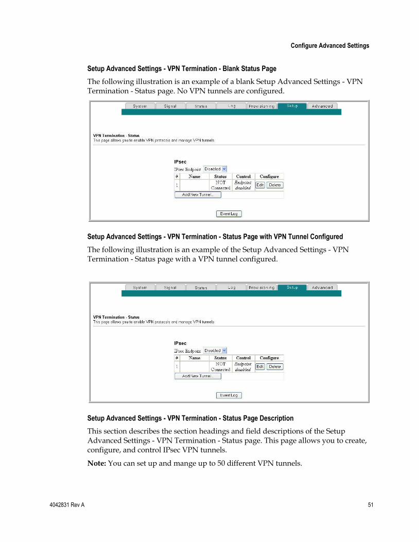
Configure Advanced Settings
4042831 Rev A 51
Setup Advanced Settings - VPN Termination - Blank Status Page
The following illustration is an example of a blank Setup Advanced Settings - VPN Termination - Status page. No VPN tunnels are configured.
Setup Advanced Settings - VPN Termination - Status Page with VPN Tunnel Configured
The following illustration is an example of the Setup Advanced Settings - VPN Termination - Status page with a VPN tunnel configured.
Setup Advanced Settings - VPN Termination - Status Page Description
This section describes the section headings and field descriptions of the Setup Advanced Settings - VPN Termination - Status page. This page allows you to create, configure, and control IPsec VPN tunnels.
Note: You can set up and mange up to 50 different VPN tunnels.
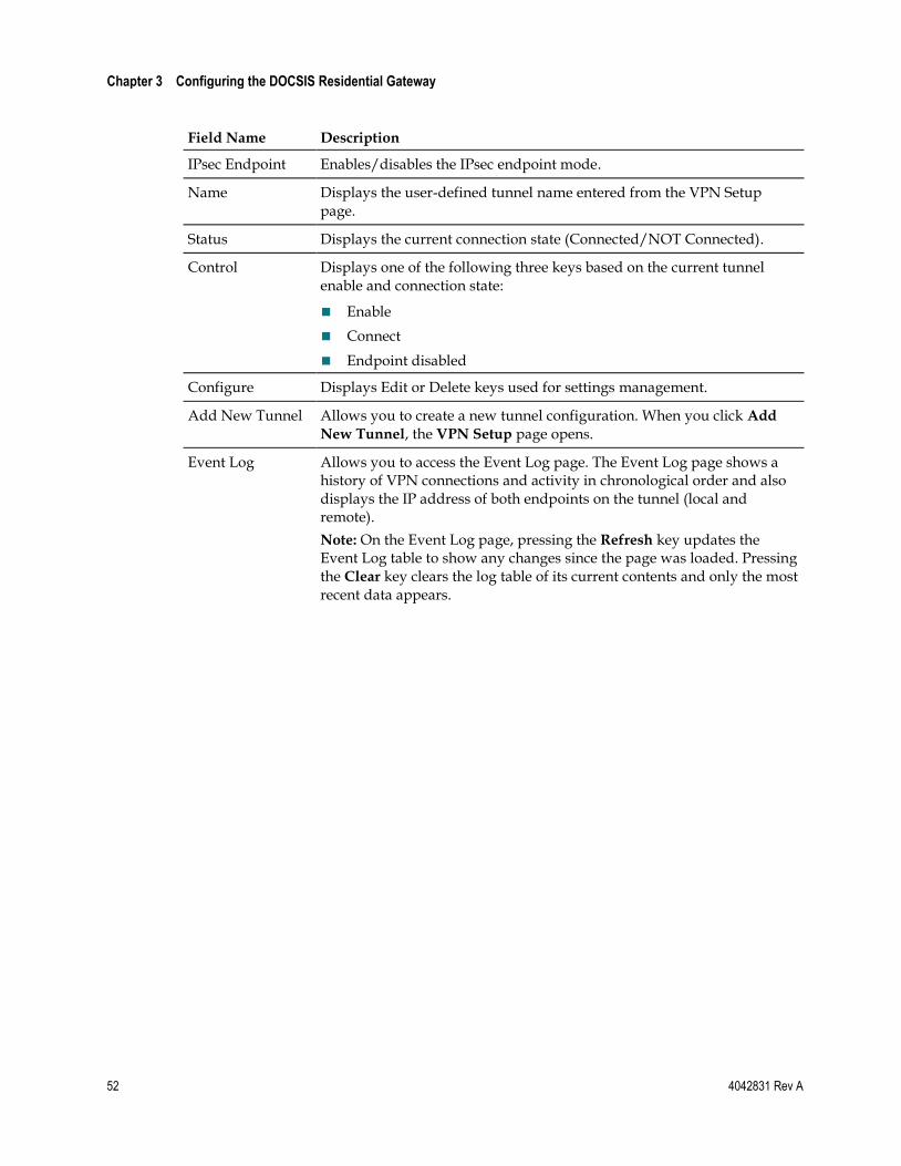
Chapter 3 Configuring the DOCSIS Residential Gateway
52 4042831 Rev A
Field Name Description
IPsec Endpoint Enables/disables the IPsec endpoint mode.
Name Displays the user-defined tunnel name entered from the VPN Setup page.
Status Displays the current connection state (Connected/NOT Connected).
Control Displays one of the following three keys based on the current tunnel enable and connection state:
Enable
Connect
Endpoint disabled
Configure Displays Edit or Delete keys used for settings management.
Add New Tunnel Allows you to create a new tunnel configuration. When you click Add
New Tunnel, the VPN Setup page opens.
Event Log Allows you to access the Event Log page. The Event Log page shows a history of VPN connections and activity in chronological order and also displays the IP address of both endpoints on the tunnel (local and remote).
Note: On the Event Log page, pressing the Refresh key updates the Event Log table to show any changes since the page was loaded. Pressing the Clear key clears the log table of its current contents and only the most recent data appears.
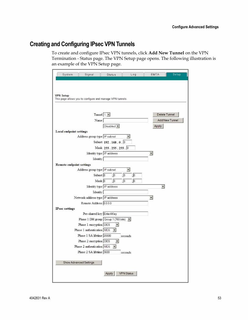
Configure Advanced Settings
4042831 Rev A 53
Creating and Configuring IPsec VPN Tunnels
To create and configure IPsec VPN tunnels, click Add New Tunnel on the VPN Termination - Status page. The VPN Setup page opens. The following illustration is an example of the VPN Setup page.
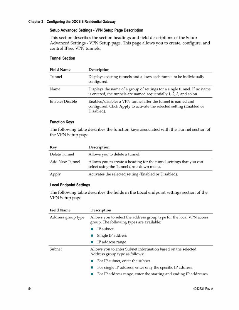
Chapter 3 Configuring the DOCSIS Residential Gateway
54 4042831 Rev A
Setup Advanced Settings - VPN Setup Page Description
This section describes the section headings and field descriptions of the Setup Advanced Settings - VPN Setup page. This page allows you to create, configure, and control IPsec VPN tunnels.
Tunnel Section
Field Name Description
Tunnel Displays existing tunnels and allows each tunnel to be individually configured.
Name Displays the name of a group of settings for a single tunnel. If no name is entered, the tunnels are named sequentially 1, 2, 3, and so on.
Enable/Disable Enables/disables a VPN tunnel after the tunnel is named and configured. Click Apply to activate the selected setting (Enabled or Disabled).
Function Keys
The following table describes the function keys associated with the Tunnel section of the VPN Setup page.
Key Description
Delete Tunnel Allows you to delete a tunnel.
Add New Tunnel Allows you to create a heading for the tunnel settings that you can select using the Tunnel drop-down menu.
Apply Activates the selected setting (Enabled or Disabled).
Local Endpoint Settings
The following table describes the fields in the Local endpoint settings section of the VPN Setup page.
Field Name Description
Address group type Allows you to select the address group type for the local VPN access group. The following types are available:
IP subnet
Single IP address
IP address range
Subnet Allows you to enter Subnet information based on the selected Address group type as follows:
For IP subnet, enter the subnet.
For single IP address, enter only the specific IP address.
For IP address range, enter the starting and ending IP addresses.
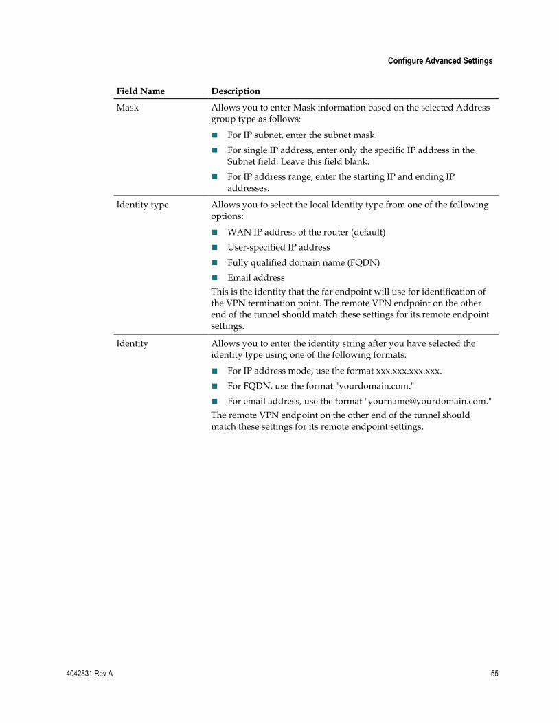
Configure Advanced Settings
4042831 Rev A 55
Field Name Description
Mask Allows you to enter Mask information based on the selected Address group type as follows:
For IP subnet, enter the subnet mask.
For single IP address, enter only the specific IP address in the Subnet field. Leave this field blank.
For IP address range, enter the starting IP and ending IP addresses.
Identity type Allows you to select the local Identity type from one of the following options:
WAN IP address of the router (default)
User-specified IP address
Fully qualified domain name (FQDN)
Email address
This is the identity that the far endpoint will use for identification of the VPN termination point. The remote VPN endpoint on the other end of the tunnel should match these settings for its remote endpoint settings.
Identity Allows you to enter the identity string after you have selected the identity type using one of the following formats:
For IP address mode, use the format xxx.xxx.xxx.xxx.
For FQDN, use the format "yourdomain.com."
For email address, use the format "[email protected]."
The remote VPN endpoint on the other end of the tunnel should match these settings for its remote endpoint settings.
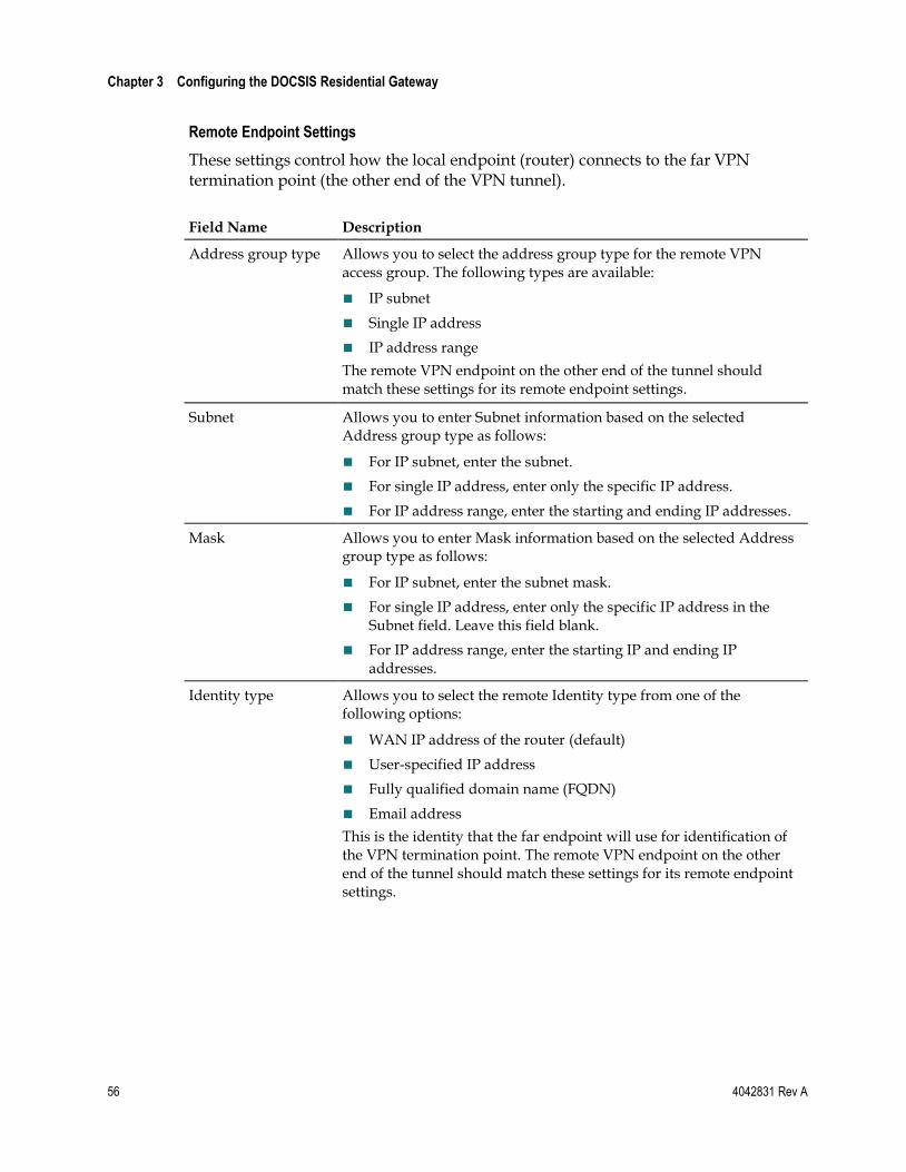
Chapter 3 Configuring the DOCSIS Residential Gateway
56 4042831 Rev A
Remote Endpoint Settings
These settings control how the local endpoint (router) connects to the far VPN termination point (the other end of the VPN tunnel).
Field Name Description
Address group type Allows you to select the address group type for the remote VPN access group. The following types are available:
IP subnet
Single IP address
IP address range
The remote VPN endpoint on the other end of the tunnel should match these settings for its remote endpoint settings.
Subnet Allows you to enter Subnet information based on the selected Address group type as follows:
For IP subnet, enter the subnet.
For single IP address, enter only the specific IP address.
For IP address range, enter the starting and ending IP addresses.
Mask Allows you to enter Mask information based on the selected Address group type as follows:
For IP subnet, enter the subnet mask.
For single IP address, enter only the specific IP address in the Subnet field. Leave this field blank.
For IP address range, enter the starting IP and ending IP addresses.
Identity type Allows you to select the remote Identity type from one of the following options:
WAN IP address of the router (default)
User-specified IP address
Fully qualified domain name (FQDN)
Email address
This is the identity that the far endpoint will use for identification of the VPN termination point. The remote VPN endpoint on the other end of the tunnel should match these settings for its remote endpoint settings.
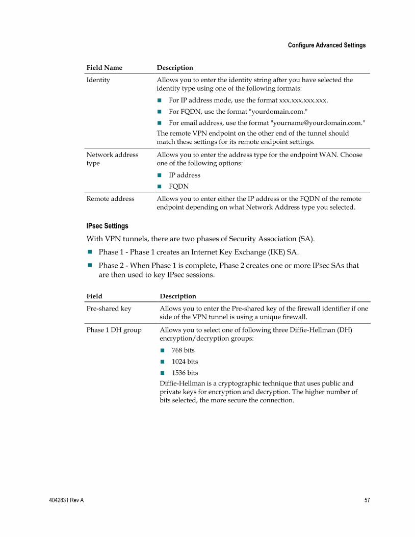
Configure Advanced Settings
4042831 Rev A 57
Field Name Description
Identity Allows you to enter the identity string after you have selected the identity type using one of the following formats:
For IP address mode, use the format xxx.xxx.xxx.xxx.
For FQDN, use the format "yourdomain.com."
For email address, use the format "[email protected]."
The remote VPN endpoint on the other end of the tunnel should match these settings for its remote endpoint settings.
Network address type
Allows you to enter the address type for the endpoint WAN. Choose one of the following options:
IP address
FQDN
Remote address Allows you to enter either the IP address or the FQDN of the remote endpoint depending on what Network Address type you selected.
IPsec Settings
With VPN tunnels, there are two phases of Security Association (SA).
Phase 1 - Phase 1 creates an Internet Key Exchange (IKE) SA.
Phase 2 - When Phase 1 is complete, Phase 2 creates one or more IPsec SAs that are then used to key IPsec sessions.
Field Description
Pre-shared key Allows you to enter the Pre-shared key of the firewall identifier if one side of the VPN tunnel is using a unique firewall.
Phase 1 DH group Allows you to select one of following three Diffie-Hellman (DH) encryption/decryption groups:
768 bits
1024 bits
1536 bits
Diffie-Hellman is a cryptographic technique that uses public and private keys for encryption and decryption. The higher number of bits selected, the more secure the connection.
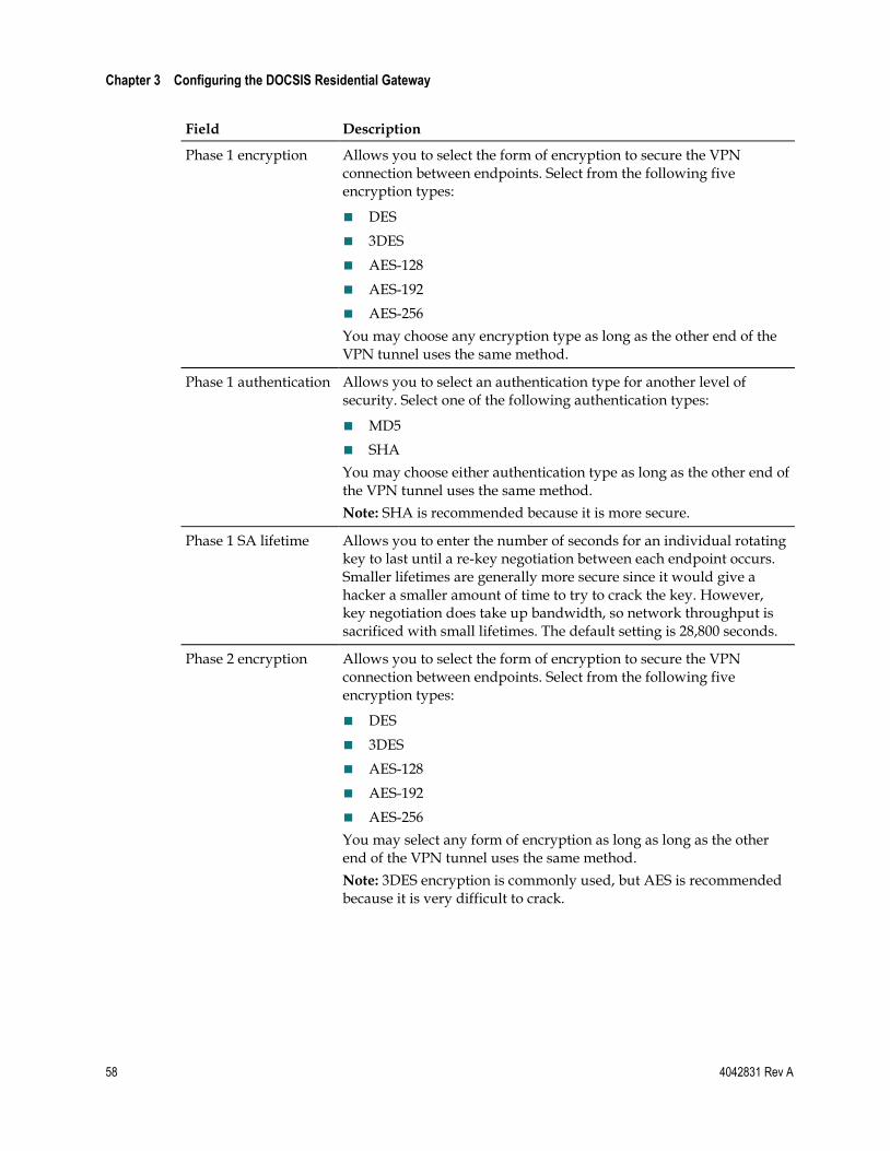
Chapter 3 Configuring the DOCSIS Residential Gateway
58 4042831 Rev A
Field Description
Phase 1 encryption Allows you to select the form of encryption to secure the VPN connection between endpoints. Select from the following five encryption types:
DES
3DES
AES-128
AES-192
AES-256
You may choose any encryption type as long as the other end of the VPN tunnel uses the same method.
Phase 1 authentication Allows you to select an authentication type for another level of security. Select one of the following authentication types:
MD5
SHA
You may choose either authentication type as long as the other end of the VPN tunnel uses the same method.
Note: SHA is recommended because it is more secure.
Phase 1 SA lifetime Allows you to enter the number of seconds for an individual rotating key to last until a re-key negotiation between each endpoint occurs. Smaller lifetimes are generally more secure since it would give a hacker a smaller amount of time to try to crack the key. However, key negotiation does take up bandwidth, so network throughput is sacrificed with small lifetimes. The default setting is 28,800 seconds.
Phase 2 encryption Allows you to select the form of encryption to secure the VPN connection between endpoints. Select from the following five encryption types:
DES
3DES
AES-128
AES-192
AES-256
You may select any form of encryption as long as long as the other end of the VPN tunnel uses the same method.
Note: 3DES encryption is commonly used, but AES is recommended because it is very difficult to crack.
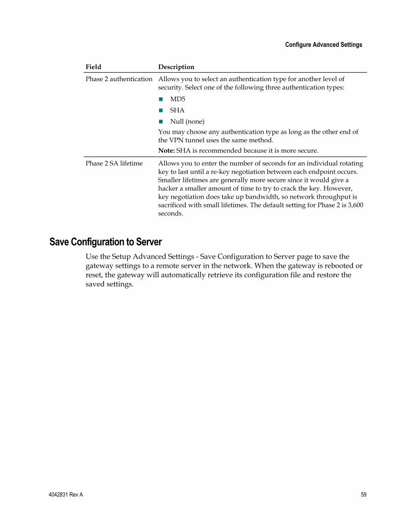
Configure Advanced Settings
4042831 Rev A 59
Field Description
Phase 2 authentication Allows you to select an authentication type for another level of security. Select one of the following three authentication types:
MD5
SHA
Null (none)
You may choose any authentication type as long as the other end of the VPN tunnel uses the same method.
Note: SHA is recommended because it is more secure.
Phase 2 SA lifetime Allows you to enter the number of seconds for an individual rotating key to last until a re-key negotiation between each endpoint occurs. Smaller lifetimes are generally more secure since it would give a hacker a smaller amount of time to try to crack the key. However, key negotiation does take up bandwidth, so network throughput is sacrificed with small lifetimes. The default setting for Phase 2 is 3,600 seconds.
Save Configuration to Server
Use the Setup Advanced Settings - Save Configuration to Server page to save the gateway settings to a remote server in the network. When the gateway is rebooted or reset, the gateway will automatically retrieve its configuration file and restore the saved settings.
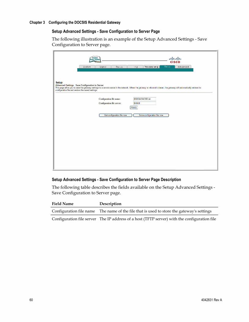
Chapter 3 Configuring the DOCSIS Residential Gateway
60 4042831 Rev A
Setup Advanced Settings - Save Configuration to Server Page
The following illustration is an example of the Setup Advanced Settings - Save Configuration to Server page.
Setup Advanced Settings - Save Configuration to Server Page Description
The following table describes the fields available on the Setup Advanced Settings - Save Configuration to Server page.
Field Name Description
Configuration file name The name of the file that is used to store the gateway's settings
Configuration file server The IP address of a host (TFTP server) with the configuration file
Configure Advanced Settings
4042831 Rev A 61
Function Keys
The following table describes the function keys available on the Setup Advanced Settings - Save Configuration to Server page.
Key Description
Get configuration file now
Click to retrieve file used to store the gateway's settings.
Save configuration file now
Click to save the gateway's settings.
Apply Click to save changes without closing the page.
Chapter 3 Configuring the DOCSIS Residential Gateway
62 4042831 Rev A
Configure Firewall Settings This section describes how to configure Firewall settings for the residential gateway.
Configuring Firewall Protection
Use the Setup Firewall - Options page to configure web page filtering and firewall protection. This page allows you to enable various firewall protection filters.
Note: If you are not familiar with the advanced settings detailed in this section, contact your service provider before you attempt to change any of the residential gateway default firewall options settings.
Click Options in the Firewall section of the Setup page to access the Setup Firewall - Options page.
Setup Firewall - Options Pages
The following sections provide examples of the Setup Firewall - Options pages when the firewall option is set to provide the following levels of protection:
Off
Low
Medium
High
Note: A Low level corresponds to the previous Firewall ON setting.
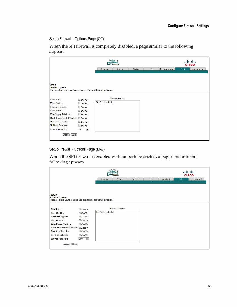
Configure Firewall Settings
4042831 Rev A 63
Setup Firewall - Options Page (Off)
When the SPI firewall is completely disabled, a page similar to the following appears.
SetupFirewall - Options Page (Low)
When the SPI firewall is enabled with no ports restricted, a page similar to the following appears.
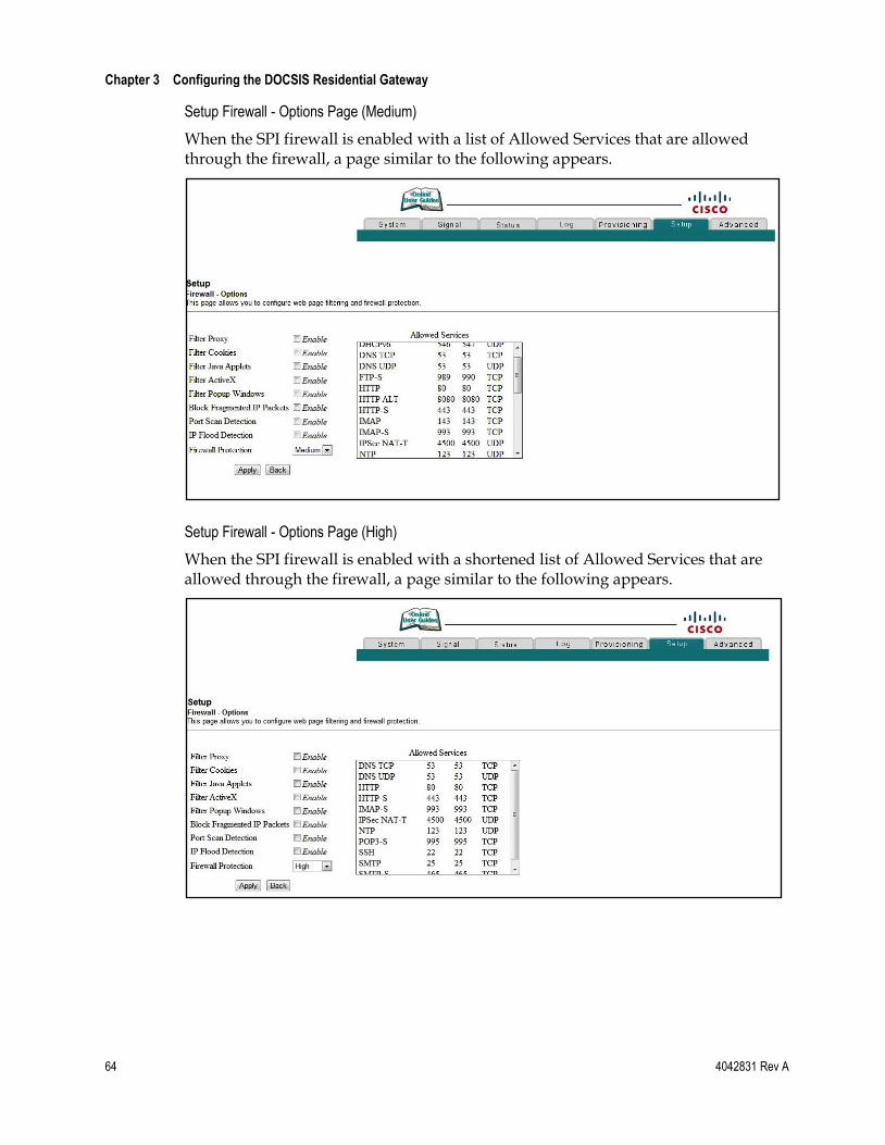
Chapter 3 Configuring the DOCSIS Residential Gateway
64 4042831 Rev A
Setup Firewall - Options Page (Medium)
When the SPI firewall is enabled with a list of Allowed Services that are allowed through the firewall, a page similar to the following appears.
Setup Firewall - Options Page (High)
When the SPI firewall is enabled with a shortened list of Allowed Services that are allowed through the firewall, a page similar to the following appears.
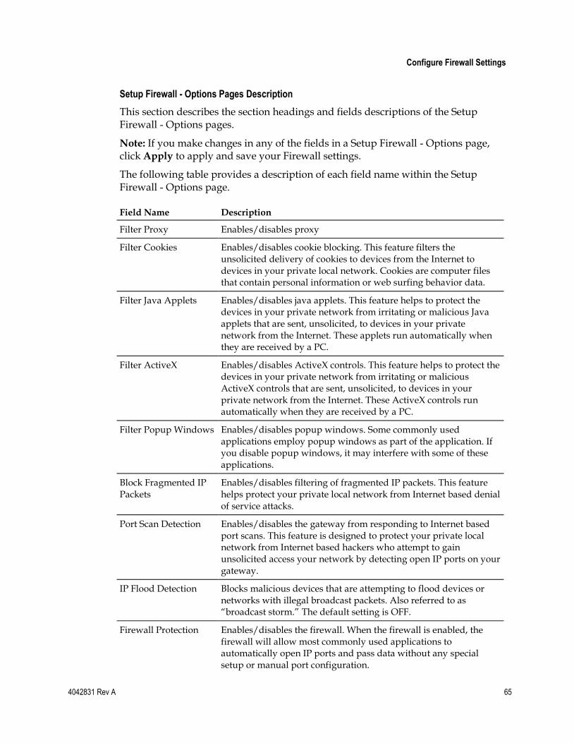
Configure Firewall Settings
4042831 Rev A 65
Setup Firewall - Options Pages Description
This section describes the section headings and fields descriptions of the Setup Firewall - Options pages.
Note: If you make changes in any of the fields in a Setup Firewall - Options page, click Apply to apply and save your Firewall settings.
The following table provides a description of each field name within the Setup Firewall - Options page.
Field Name Description
Filter Proxy Enables/disables proxy
Filter Cookies Enables/disables cookie blocking. This feature filters the unsolicited delivery of cookies to devices from the Internet to devices in your private local network. Cookies are computer files that contain personal information or web surfing behavior data.
Filter Java Applets Enables/disables java applets. This feature helps to protect the devices in your private network from irritating or malicious Java applets that are sent, unsolicited, to devices in your private network from the Internet. These applets run automatically when they are received by a PC.
Filter ActiveX Enables/disables ActiveX controls. This feature helps to protect the devices in your private network from irritating or malicious ActiveX controls that are sent, unsolicited, to devices in your private network from the Internet. These ActiveX controls run automatically when they are received by a PC.
Filter Popup Windows Enables/disables popup windows. Some commonly used applications employ popup windows as part of the application. If you disable popup windows, it may interfere with some of these applications.
Block Fragmented IP Packets
Enables/disables filtering of fragmented IP packets. This feature helps protect your private local network from Internet based denial of service attacks.
Port Scan Detection Enables/disables the gateway from responding to Internet based port scans. This feature is designed to protect your private local network from Internet based hackers who attempt to gain unsolicited access your network by detecting open IP ports on your gateway.
IP Flood Detection Blocks malicious devices that are attempting to flood devices or networks with illegal broadcast packets. Also referred to as ―broadcast storm.‖ The default setting is OFF.
Firewall Protection Enables/disables the firewall. When the firewall is enabled, the firewall will allow most commonly used applications to automatically open IP ports and pass data without any special setup or manual port configuration.
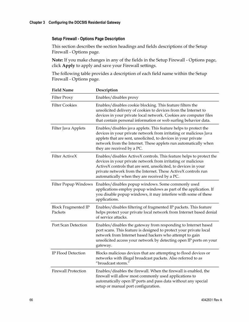
Chapter 3 Configuring the DOCSIS Residential Gateway
66 4042831 Rev A
Setup Firewall - Options Page Description
This section describes the section headings and fields descriptions of the Setup Firewall - Options page.
Note: If you make changes in any of the fields in the Setup Firewall - Options page, click Apply to apply and save your Firewall settings.
The following table provides a description of each field name within the Setup Firewall - Options page.
Field Name Description
Filter Proxy Enables/disables proxy
Filter Cookies Enables/disables cookie blocking. This feature filters the unsolicited delivery of cookies to devices from the Internet to devices in your private local network. Cookies are computer files that contain personal information or web surfing behavior data.
Filter Java Applets Enables/disables java applets. This feature helps to protect the devices in your private network from irritating or malicious Java applets that are sent, unsolicited, to devices in your private network from the Internet. These applets run automatically when they are received by a PC.
Filter ActiveX Enables/disables ActiveX controls. This feature helps to protect the devices in your private network from irritating or malicious ActiveX controls that are sent, unsolicited, to devices in your private network from the Internet. These ActiveX controls run automatically when they are received by a PC.
Filter Popup Windows Enables/disables popup windows. Some commonly used applications employ popup windows as part of the application. If you disable popup windows, it may interfere with some of these applications.
Block Fragmented IP Packets
Enables/disables filtering of fragmented IP packets. This feature helps protect your private local network from Internet based denial of service attacks.
Port Scan Detection Enables/disables the gateway from responding to Internet based port scans. This feature is designed to protect your private local network from Internet based hackers who attempt to gain unsolicited access your network by detecting open IP ports on your gateway.
IP Flood Detection Blocks malicious devices that are attempting to flood devices or networks with illegal broadcast packets. Also referred to as ―broadcast storm.‖
Firewall Protection Enables/disables the firewall. When the firewall is enabled, the firewall will allow most commonly used applications to automatically open IP ports and pass data without any special setup or manual port configuration.
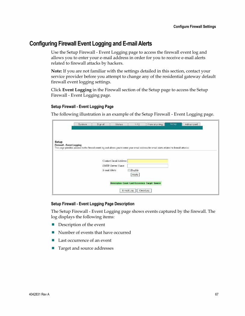
Configure Firewall Settings
4042831 Rev A 67
Configuring Firewall Event Logging and E-mail Alerts
Use the Setup Firewall - Event Logging page to access the firewall event log and allows you to enter your e-mail address in order for you to receive e-mail alerts related to firewall attacks by hackers.
Note: If you are not familiar with the settings detailed in this section, contact your service provider before you attempt to change any of the residential gateway default firewall event logging settings.
Click Event Logging in the Firewall section of the Setup page to access the Setup Firewall - Event Logging page.
Setup Firewall - Event Logging Page
The following illustration is an example of the Setup Firewall - Event Logging page.
Setup Firewall - Event Logging Page Description
The Setup Firewall - Event Logging page shows events captured by the firewall. The log displays the following items:
Description of the event
Number of events that have occurred
Last occurrence of an event
Target and source addresses
Chapter 3 Configuring the DOCSIS Residential Gateway
68 4042831 Rev A
You can configure the system to send e-mails regarding log events to the administrator in order for the administrator to monitor the firewall.
This section describes the section headings and fields descriptions of the Setup Firewall - Event Logging page.
Field Name Description
Enable E-mail Address Allows you to enter the e-mail address of the person who monitors the firewall. When an event occurs, it will be logged and an e-mail will be sent to this address automatically reporting the event.
SMTP Server Name Allows you to enter the mail server name of your outgoing mail server, or the mail server of your Internet service provider (ISP).
E-mail Alerts Allows you to enable or disable sending e-mail alerts.
Description Describes what event was detected by the gateway's firewall.
Count Displays the number of times the event has been detected.
Last Occurrence Displays the time the last occurrence of this event was detected.
Target Displays the IP address of the device in your private local network to which the event was directed along with the IP port number targeted by the event.
Source Displays the IP address of the Internet based source of the event along with the IP port number used by that device.
Function Keys
The following function keys appear on the Setup Firewall - Event Logging page.
Key Description
Apply Saves the values you enter into the fields without closing the screen.
E-mail Log Allows you to force the system to send an e-mail alert even if the E-mail Alerts box is left unchecked.
Clear Log Allows you to clear all entries in the log.
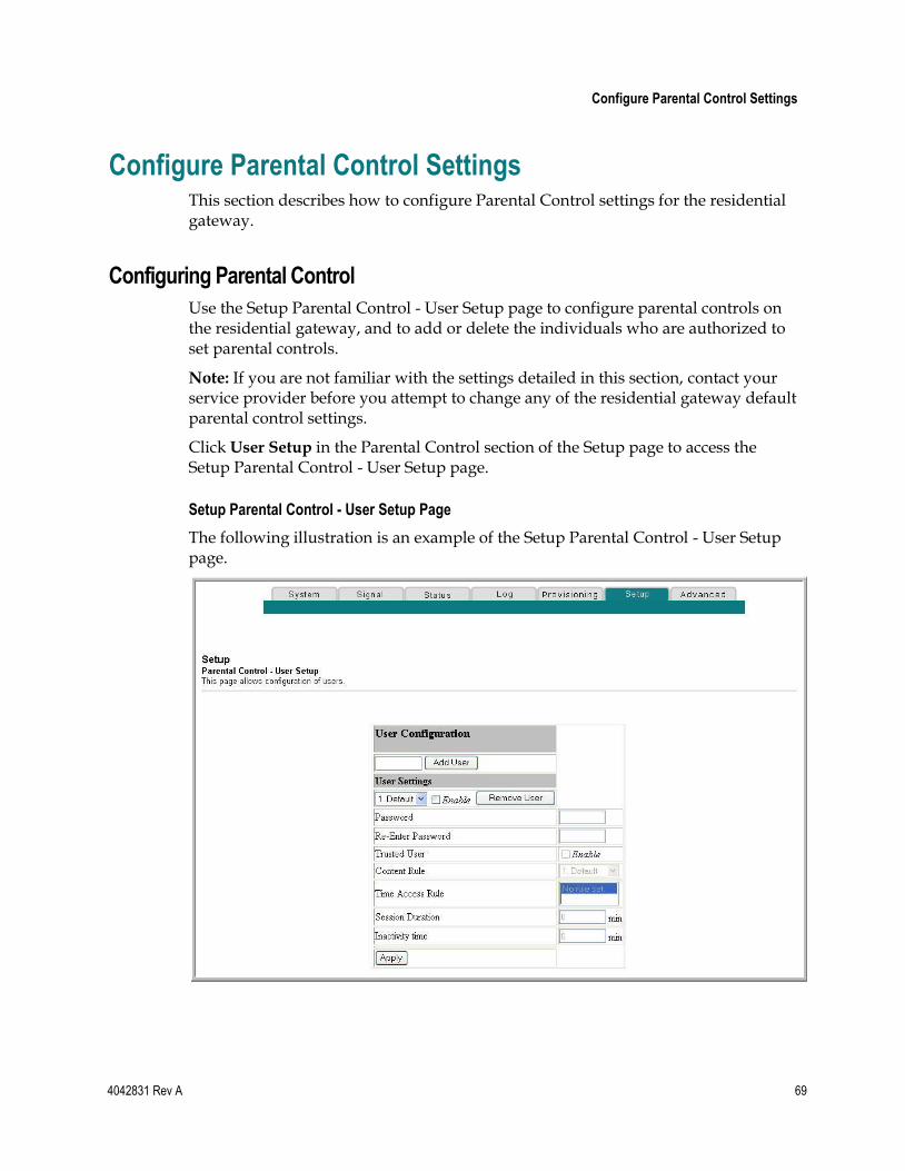
Configure Parental Control Settings
4042831 Rev A 69
Configure Parental Control Settings This section describes how to configure Parental Control settings for the residential gateway.
Configuring Parental Control
Use the Setup Parental Control - User Setup page to configure parental controls on the residential gateway, and to add or delete the individuals who are authorized to set parental controls.
Note: If you are not familiar with the settings detailed in this section, contact your service provider before you attempt to change any of the residential gateway default parental control settings.
Click User Setup in the Parental Control section of the Setup page to access the Setup Parental Control - User Setup page.
Setup Parental Control - User Setup Page
The following illustration is an example of the Setup Parental Control - User Setup page.
Chapter 3 Configuring the DOCSIS Residential Gateway
70 4042831 Rev A
Setup Parental Control - User Setup Page Description
This section describes the section headings and fields descriptions of the Setup Parental Control - User Setup page. This page allows you to set up user profiles. Each profile can be assigned customized levels of Internet access as defined by the access rules assigned to that user's profile.
Note: Once you define and enable user profiles, each user must sign-on each time they wish to access the Internet. The user can sign-on when the pop-up sign-on screen appears in their web browser. The user must enter their correct user name and password in order to gain Internet access.
Important:
Make sure to disable pop-up blockers on your web browser when using user profiles.
User names and passwords are case-sensitive.
Field Name Description
Add User Allows you to add a new user profile. Enter the name of the user and click the Add User button to add the user to the list.
User Settings Allows you to edit a user profile by using the drop-down menu to edit a user profile. The drop-down menu allows you to recall the profile to be edited. User names and passwords are case-sensitive.
Make sure to check the Enable box to activate the user profile. If a profile is not active, that user will not have any access to the Internet.
To remove a user profile, use the drop-down menu to select the user to be removed and click the Remove User button.
Password Enter the selected user's password in this field. Each user must enter their user name and password each time they use the Internet. User names and passwords are case-sensitive.
Note: The gateway will allow each user access to the Internet, subject to the rules selected on this page for that user.
Re-Enter Password Re-enter the same password for confirmation of the password in the previous field.
Trusted User Check this box if the currently selected user is to be designated a trusted user. Trusted users are not subject to Internet access rules.
Content Rule Select the Content Rule for the current user profile. Content Rules must first be defined by going to the Rules Configuration page. You can access the Rule Configuration page by clicking the Basic
Rules link under the Parental Control section of the Setup page.
Time Access Rule Select the Time Access Rule for the current user profile. Time Access Rules must first be defined by going to the Time of Day Filter page. You can access the Time of Day Filter page by clicking the Time of Day Rules link under the Parental Control section of the Setup page.
Configure Parental Control Settings
4042831 Rev A 71
Field Name Description
Session Duration 1440 minutes (factory default).
Enter the amount of time in minutes that the user will be granted Internet access beginning at the time they sign on using their user name and password.
Note: Set the Session Duration to 0 (zero) to prevent session timeout.
Inactivity time 60 minutes (factory default).
Enter the amount of time during a user session where there is no Internet access activity, indicating that the user is no longer online. If the inactivity timer is triggered, the user session will be closed automatically. In order to regain Internet access, the user must log in again with their user name and password.
Note: Set the Inactivity time value to 0 (zero) to prevent timeout due to inactivity.
Available Rules Lists available rules. Apply a rule by selecting it from the list and adding it to the current user profile.
Note: This field appears only if rules have been created. Create rules using the Parental Control Setup pages that follow next.
Current Used Rules Lists rules in use for the current user profile. You can apply a maximum of four rules to each user profile.
Note: This field appears only when a rule is associated with a user profile.
Function Keys
The following function keys appear on the Setup Parental Control - User Setup page.
Key Description
Add User Adds and saves a new user to the list of user profiles.
Remove User Removes the selected user from the list of user profiles.
Apply Saves all additions, edits, and changes.
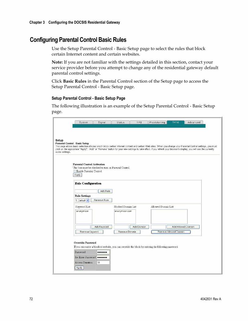
Chapter 3 Configuring the DOCSIS Residential Gateway
72 4042831 Rev A
Configuring Parental Control Basic Rules
Use the Setup Parental Control - Basic Setup page to select the rules that block certain Internet content and certain websites.
Note: If you are not familiar with the settings detailed in this section, contact your service provider before you attempt to change any of the residential gateway default parental control settings.
Click Basic Rules in the Parental Control section of the Setup page to access the Setup Parental Control - Basic Setup page.
Setup Parental Control - Basic Setup Page
The following illustration is an example of the Setup Parental Control - Basic Setup page.
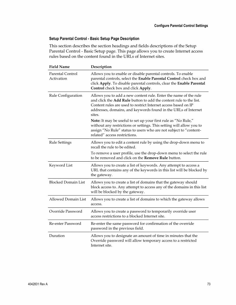
Configure Parental Control Settings
4042831 Rev A 73
Setup Parental Control - Basic Setup Page Description
This section describes the section headings and fields descriptions of the Setup Parental Control - Basic Setup page. This page allows you to create Internet access rules based on the content found in the URLs of Internet sites.
Field Name Description
Parental Control Activation
Allows you to enable or disable parental controls. To enable parental controls, select the Enable Parental Control check box and click Apply. To disable parental controls, clear the Enable Parental
Control check box and click Apply.
Rule Configuration Allows you to add a new content rule. Enter the name of the rule and click the Add Rule button to add the content rule to the list. Content rules are used to restrict Internet access based on IP addresses, domains, and keywords found in the URLs of Internet sites.
Note: It may be useful to set up your first rule as ―No Rule,‖ without any restrictions or settings. This setting will allow you to assign ―No Rule‖ status to users who are not subject to ―content-related‖ access restrictions.
Rule Settings Allows you to edit a content rule by using the drop-down menu to recall the rule to be edited.
To remove a user profile, use the drop-down menu to select the rule to be removed and click on the Remove Rule button.
Keyword List Allows you to create a list of keywords. Any attempt to access a URL that contains any of the keywords in this list will be blocked by the gateway.
Blocked Domain List Allows you to create a list of domains that the gateway should block access to. Any attempt to access any of the domains in this list will be blocked by the gateway.
Allowed Domain List Allows you to create a list of domains to which the gateway allows access.
Override Password Allows you to create a password to temporarily override user access restrictions to a blocked Internet site.
Re-enter Password Re-enter the same password for confirmation of the override password in the previous field.
Duration Allows you to designate an amount of time in minutes that the Override password will allow temporary access to a restricted Internet site.
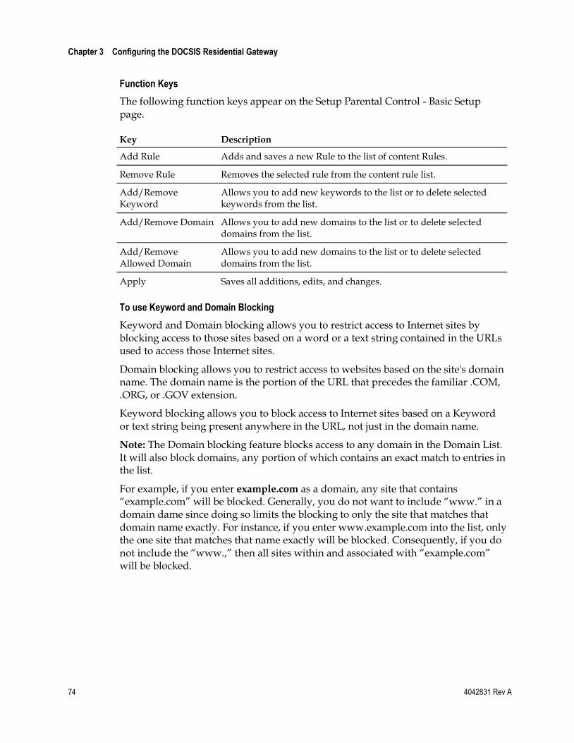
Chapter 3 Configuring the DOCSIS Residential Gateway
74 4042831 Rev A
Function Keys
The following function keys appear on the Setup Parental Control - Basic Setup page.
Key Description
Add Rule Adds and saves a new Rule to the list of content Rules.
Remove Rule Removes the selected rule from the content rule list.
Add/Remove Keyword
Allows you to add new keywords to the list or to delete selected keywords from the list.
Add/Remove Domain Allows you to add new domains to the list or to delete selected domains from the list.
Add/Remove Allowed Domain
Allows you to add new domains to the list or to delete selected domains from the list.
Apply Saves all additions, edits, and changes.
To use Keyword and Domain Blocking
Keyword and Domain blocking allows you to restrict access to Internet sites by blocking access to those sites based on a word or a text string contained in the URLs used to access those Internet sites.
Domain blocking allows you to restrict access to websites based on the site's domain name. The domain name is the portion of the URL that precedes the familiar .COM, .ORG, or .GOV extension.
Keyword blocking allows you to block access to Internet sites based on a Keyword or text string being present anywhere in the URL, not just in the domain name.
Note: The Domain blocking feature blocks access to any domain in the Domain List. It will also block domains, any portion of which contains an exact match to entries in the list.
For example, if you enter example.com as a domain, any site that contains ―example.com‖ will be blocked. Generally, you do not want to include ―www.‖ in a domain dame since doing so limits the blocking to only the site that matches that domain name exactly. For instance, if you enter www.example.com into the list, only the one site that matches that name exactly will be blocked. Consequently, if you do not include the ―www.,‖ then all sites within and associated with ―example.com‖ will be blocked.
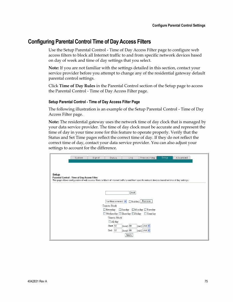
Configure Parental Control Settings
4042831 Rev A 75
Configuring Parental Control Time of Day Access Filters
Use the Setup Parental Control - Time of Day Access Filter page to configure web access filters to block all Internet traffic to and from specific network devices based on day of week and time of day settings that you select.
Note: If you are not familiar with the settings detailed in this section, contact your service provider before you attempt to change any of the residential gateway default parental control settings.
Click Time of Day Rules in the Parental Control section of the Setup page to access the Parental Control - Time of Day Access Filter page.
Setup Parental Control - Time of Day Access Filter Page
The following illustration is an example of the Setup Parental Control - Time of Day Access Filter page.
Note: The residential gateway uses the network time of day clock that is managed by your data service provider. The time of day clock must be accurate and represent the time of day in your time zone for this feature to operate properly. Verify that the Status and Set Time pages reflect the correct time of day. If they do not reflect the correct time of day, contact your data service provider. You can also adjust your settings to account for the difference.
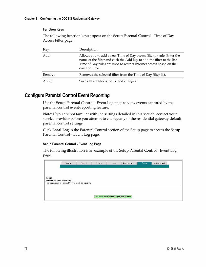
Chapter 3 Configuring the DOCSIS Residential Gateway
76 4042831 Rev A
Function Keys
The following function keys appear on the Setup Parental Control - Time of Day Access Filter page.
Key Description
Add Allows you to add a new Time of Day access filter or rule. Enter the name of the filter and click the Add key to add the filter to the list. Time of Day rules are used to restrict Internet access based on the day and time.
Remove Removes the selected filter from the Time of Day filter list.
Apply Saves all additions, edits, and changes.
Configure Parental Control Event Reporting
Use the Setup Parental Control - Event Log page to view events captured by the parental control event-reporting feature.
Note: If you are not familiar with the settings detailed in this section, contact your service provider before you attempt to change any of the residential gateway default parental control settings.
Click Local Log in the Parental Control section of the Setup page to access the Setup Parental Control - Event Log page.
Setup Parental Control - Event Log Page
The following illustration is an example of the Setup Parental Control - Event Log page.
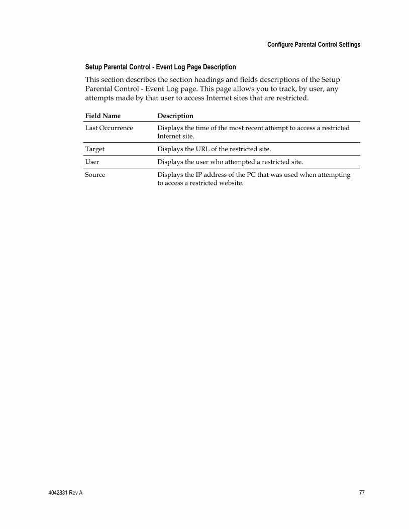
Configure Parental Control Settings
4042831 Rev A 77
Setup Parental Control - Event Log Page Description
This section describes the section headings and fields descriptions of the Setup Parental Control - Event Log page. This page allows you to track, by user, any attempts made by that user to access Internet sites that are restricted.
Field Name Description
Last Occurrence Displays the time of the most recent attempt to access a restricted Internet site.
Target Displays the URL of the restricted site.
User Displays the user who attempted a restricted site.
Source Displays the IP address of the PC that was used when attempting to access a restricted website.
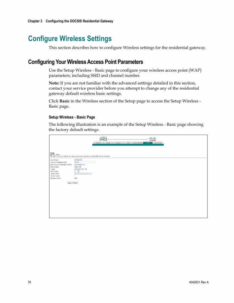
Chapter 3 Configuring the DOCSIS Residential Gateway
78 4042831 Rev A
Configure Wireless Settings This section describes how to configure Wireless settings for the residential gateway.
Configuring Your Wireless Access Point Parameters
Use the Setup Wireless - Basic page to configure your wireless access point (WAP) parameters, including SSID and channel number.
Note: If you are not familiar with the advanced settings detailed in this section, contact your service provider before you attempt to change any of the residential gateway default wireless basic settings.
Click Basic in the Wireless section of the Setup page to access the Setup Wireless - Basic page.
Setup Wireless - Basic Page
The following illustration is an example of the Setup Wireless - Basic page showing the factory default settings.
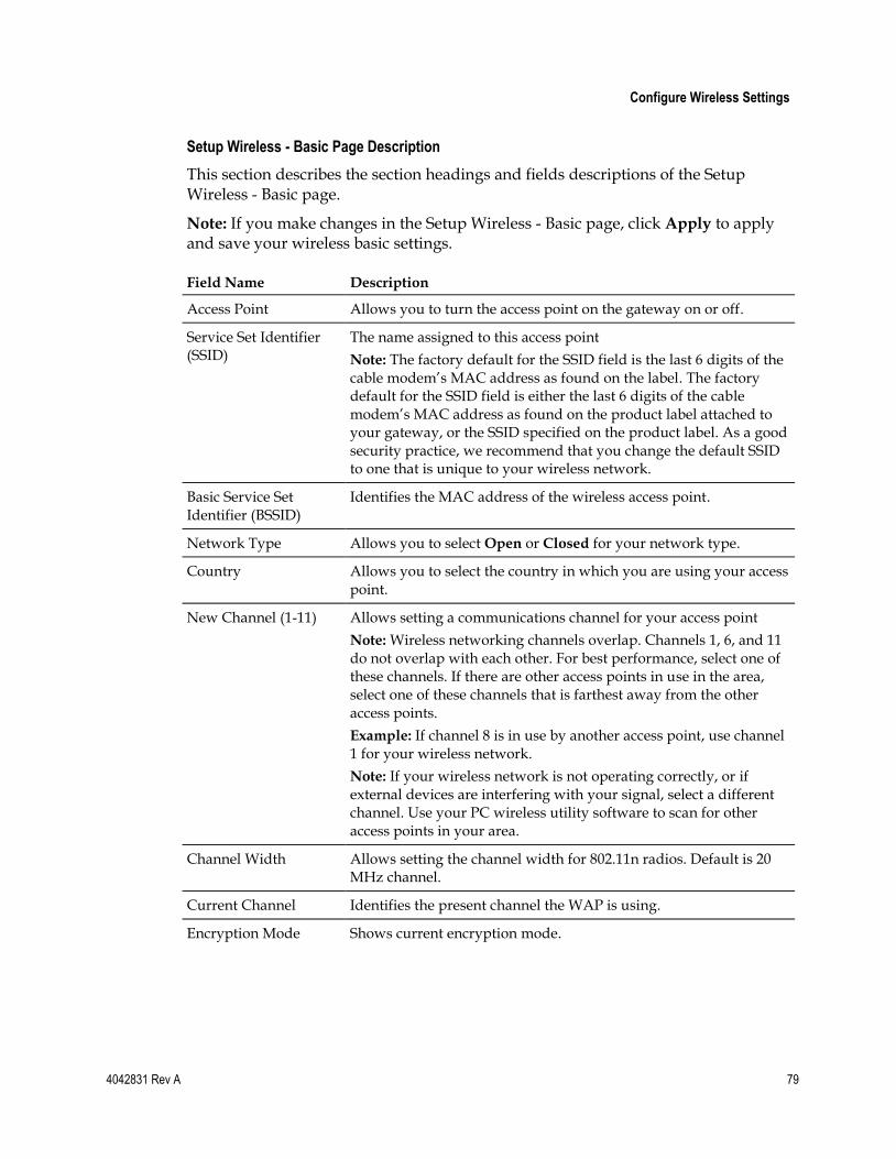
Configure Wireless Settings
4042831 Rev A 79
Setup Wireless - Basic Page Description
This section describes the section headings and fields descriptions of the Setup Wireless - Basic page.
Note: If you make changes in the Setup Wireless - Basic page, click Apply to apply and save your wireless basic settings.
Field Name Description
Access Point Allows you to turn the access point on the gateway on or off.
Service Set Identifier (SSID)
The name assigned to this access point
Note: The factory default for the SSID field is the last 6 digits of the cable modem’s MAC address as found on the label. The factory default for the SSID field is either the last 6 digits of the cable modem’s MAC address as found on the product label attached to your gateway, or the SSID specified on the product label. As a good security practice, we recommend that you change the default SSID to one that is unique to your wireless network.
Basic Service Set Identifier (BSSID)
Identifies the MAC address of the wireless access point.
Network Type Allows you to select Open or Closed for your network type.
Country Allows you to select the country in which you are using your access point.
New Channel (1-11) Allows setting a communications channel for your access point
Note: Wireless networking channels overlap. Channels 1, 6, and 11 do not overlap with each other. For best performance, select one of these channels. If there are other access points in use in the area, select one of these channels that is farthest away from the other access points.
Example: If channel 8 is in use by another access point, use channel 1 for your wireless network.
Note: If your wireless network is not operating correctly, or if external devices are interfering with your signal, select a different channel. Use your PC wireless utility software to scan for other access points in your area.
Channel Width Allows setting the channel width for 802.11n radios. Default is 20 MHz channel.
Current Channel Identifies the present channel the WAP is using.
Encryption Mode Shows current encryption mode.
Chapter 3 Configuring the DOCSIS Residential Gateway
80 4042831 Rev A
Configuring Your Wireless Network Security and Encryption Parameters
Use the Setup Wireless - Security page to configure your WAP wireless equivalent privacy (WEP) encryption keys and authentication.
Note: If you are not familiar with the advanced settings detailed in this section, contact your service provider before you attempt to change any of the residential gateway default wireless security settings.
Click Security in the Wireless section of the Setup page to access the Setup Wireless - Security page.
Important: Your residential gateway ships from the factory with WPA security enabled to provide you with a basic level of wireless network security. To gain initial access to your wireless network, select WPA security on your computer's wireless adapter and enter the WPA key to match the key setup in your gateway. The factory default WPA key in the gateway is the serial number of the device. You can continue to use this factory default key. However, to maximize your wireless security, it is highly recommended that you use something other than the factory default key.
Using Wi-Fi Protected Setup (WPS)
Wi-Fi Protected Setup (WPS) allows you to easily attach wireless devices that also support WPS. When WPS is enabled and activated, you can attach other wireless clients with the press of a button or by entering the station PIN.
After enabling WPS, you can activate the automatic registration by clicking the Start WPS button in the WPS section of the Setup Wireless - Security page.
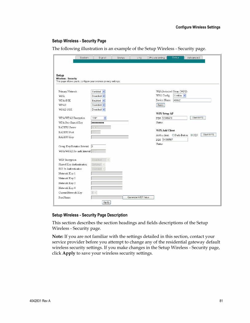
Configure Wireless Settings
4042831 Rev A 81
Setup Wireless - Security Page
The following illustration is an example of the Setup Wireless - Security page.
Setup Wireless - Security Page Description
This section describes the section headings and fields descriptions of the Setup Wireless - Security page.
Note: If you are not familiar with the settings detailed in this section, contact your service provider before you attempt to change any of the residential gateway default wireless security settings. If you make changes in the Setup Wireless - Security page, click Apply to save your wireless security settings.
Chapter 3 Configuring the DOCSIS Residential Gateway
82 4042831 Rev A
Field Name Description
Network Authentication
Network Authentication allows only authorized users to gain access to your wireless network. Only users with an authorized user name, password, or pre-shared key are allowed access to the wireless network.
Select from the following Network Authentication protocols:
Primary Network
WPA
WPA-PSK
WPA2
WPA2-PSK
Note: Network Authentication restricts access to your wireless network to only authorized computers or users. Authentication does not protect the data you send over the wireless network connection. You must enable encryption to protect data that is transmitted over your wireless network.
WPA/WPA2 Encryption
Allows you to select a WPA/WPA2 security method. The factory default security is WPA-PSK.
TKIP (Temporal Key Integrity Protocol)
AES (Advanced Encryption Standard) - factory default
TKIP-AES
WPA Pre-Shared Key Allows you to set a WPA Pre-Shared key. Enter a text string in this field. The text string or phrase is used to generate a unique set of encryption keys for your network. Use this string to set up wireless devices in your network.
The factory default security key is the 9-digit serial number of the gateway. For example: 20167792. See What Types of Service Accounts Do I Need? (on page 8) for the location of the serial number on the label.
The PSK can be either a text string or a 64 character hexadecimal number.
The text string must be an ASCII character string with a minimum of 8 characters but no more than 63.
Note: Not all wireless adapter devices support PSK. For these devices, you must enter the encryption keys exactly as they appear in the in wireless gateway fields in the preceding illustration of the Setup Wireless Security page.
Configure Wireless Settings
4042831 Rev A 83
Field Name Description
RADIUS Server Allows you to enter the IP address of the RADIUS server used for authentication and encryption key derivation.
This field is used with 802.1x and WPA Network Authentication.
The factory default for this field is 0.0.0.0.
RADIUS Port Determines the port number of the RADIUS server. The port number is usually 1812 (factory default) or 1645, depending on the server used.
This field is used with 802.1x and WPA Network Authentication.
RADIUS Key Allows you to set the Shared Secret key for your RADIUS connection.
The factory default for this field is empty.
This field is used with 802.1x and WPA Network Authentication.
Group Key Rotation Interval
Allows you to set the WPA Group Key Rotation Interval in seconds. This only applies when WPA or WPA2 Network Authentication is enabled.
Set this value to 0 (factory default) to disable periodic rekeying. The valid range is 1 to 4,294,967,295 seconds.
WPA/WPA2 Re-auth Interval
Allows you to set the WPA/WPA2 Re-authorization Interval in seconds. This only applies when WPA/WPA2 Network Authentication is enabled.
Set this value to 0 (factory default) to disable periodic rekeying. The valid range is 1 to 4,294,967,295 seconds.
Chapter 3 Configuring the DOCSIS Residential Gateway
84 4042831 Rev A
Field Name Description
WEP Encryption Allows you to enable data encryption to help secure the data that is sent over your wireless network.
WEP 128-bit
128-bit or 64-bit static key data encryption can be selected when the network is configured to have no authentication.
128-bit static key data encryption is automatically selected when 802.1x network authentication is enabled.
Notes:
Static key authentication uses one of the four encryption keys, as defined below, to encrypt your data. You must manually change keys. The keys do not change or rotate automatically as they do with TKIP.
64-bit and 40-bit encryption are two different names for the same encryption.
128-bit and 104-bit encryption are two different names for the same encryption.
Shared Key Authentication
Allows you to determine if Shared Key Authentication is used in the network. Shared Key Authentication can be used when there is no other network authentication in the network.
Optional (factory default) - Wireless clients can associate with the wireless access point without authentication.
Required - Only wireless clients with a valid network key are allowed to associate with the access point.
802.1x Authentication Allows you to use 802.1x authentication with WEP encryption (similar to when WPA or WPA2 is enabled).
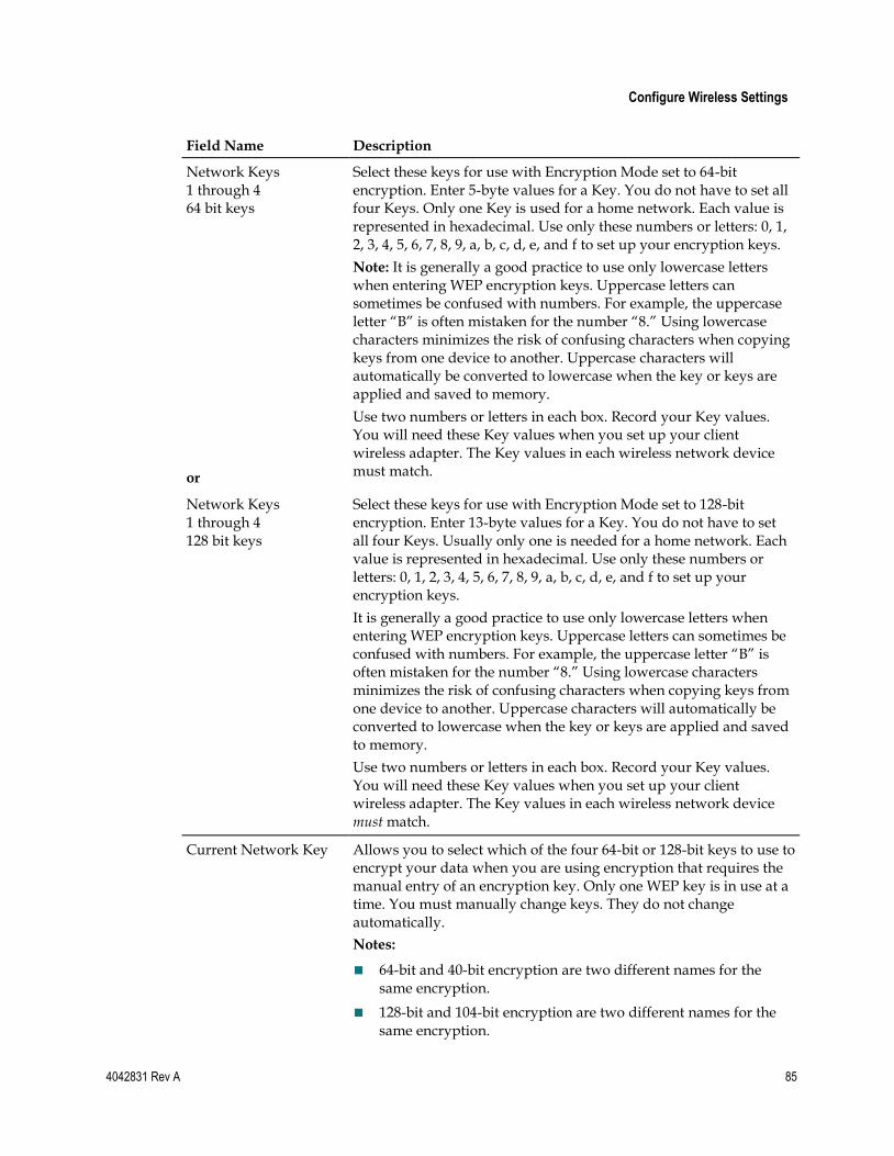
Configure Wireless Settings
4042831 Rev A 85
Field Name Description
Network Keys 1 through 4 64 bit keys
or
Select these keys for use with Encryption Mode set to 64-bit encryption. Enter 5-byte values for a Key. You do not have to set all four Keys. Only one Key is used for a home network. Each value is represented in hexadecimal. Use only these numbers or letters: 0, 1, 2, 3, 4, 5, 6, 7, 8, 9, a, b, c, d, e, and f to set up your encryption keys.
Note: It is generally a good practice to use only lowercase letters when entering WEP encryption keys. Uppercase letters can sometimes be confused with numbers. For example, the uppercase letter ―B‖ is often mistaken for the number ―8.‖ Using lowercase characters minimizes the risk of confusing characters when copying keys from one device to another. Uppercase characters will automatically be converted to lowercase when the key or keys are applied and saved to memory.
Use two numbers or letters in each box. Record your Key values. You will need these Key values when you set up your client wireless adapter. The Key values in each wireless network device must match.
Network Keys 1 through 4 128 bit keys
Select these keys for use with Encryption Mode set to 128-bit encryption. Enter 13-byte values for a Key. You do not have to set all four Keys. Usually only one is needed for a home network. Each value is represented in hexadecimal. Use only these numbers or letters: 0, 1, 2, 3, 4, 5, 6, 7, 8, 9, a, b, c, d, e, and f to set up your encryption keys.
It is generally a good practice to use only lowercase letters when entering WEP encryption keys. Uppercase letters can sometimes be confused with numbers. For example, the uppercase letter ―B‖ is often mistaken for the number ―8.‖ Using lowercase characters minimizes the risk of confusing characters when copying keys from one device to another. Uppercase characters will automatically be converted to lowercase when the key or keys are applied and saved to memory.
Use two numbers or letters in each box. Record your Key values. You will need these Key values when you set up your client wireless adapter. The Key values in each wireless network device must match.
Current Network Key Allows you to select which of the four 64-bit or 128-bit keys to use to encrypt your data when you are using encryption that requires the manual entry of an encryption key. Only one WEP key is in use at a time. You must manually change keys. They do not change automatically.
Notes:
64-bit and 40-bit encryption are two different names for the same encryption.
128-bit and 104-bit encryption are two different names for the same encryption.
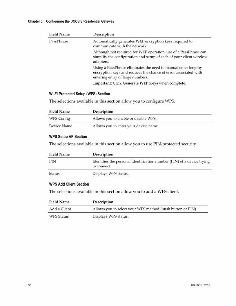
Chapter 3 Configuring the DOCSIS Residential Gateway
86 4042831 Rev A
Field Name Description
PassPhrase Automatically generates WEP encryption keys required to communicate with the network.
Although not required for WEP operation, use of a PassPhrase can simplify the configuration and setup of each of your client wireless adapters.
Using a PassPhrase eliminates the need to manual enter lengthy encryption keys and reduces the chance of error associated with entering entry of large numbers.
Important: Click Generate WEP Keys when complete.
Wi-Fi Protected Setup (WPS) Section
The selections available in this section allow you to configure WPS.
Field Name Description
WPS Config Allows you to enable or disable WPS.
Device Name Allows you to enter your device name.
WPS Setup AP Section
The selections available in this section allow you to use PIN-protected security.
Field Name Description
PIN Identifies the personal identification number (PIN) of a device trying to connect.
Status Displays WPS status.
WPS Add Client Section
The selections available in this section allow you to add a WPS client.
Field Name Description
Add a Client Allows you to select your WPS method (push button or PIN)
WPS Status Displays WPS status.
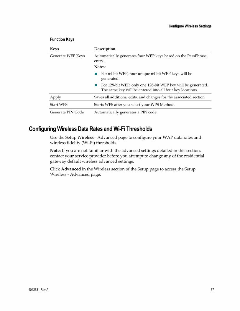
Configure Wireless Settings
4042831 Rev A 87
Function Keys
Keys Description
Generate WEP Keys Automatically generates four WEP keys based on the PassPhrase entry.
Notes:
For 64-bit WEP, four unique 64-bit WEP keys will be generated.
For 128-bit WEP, only one 128-bit WEP key will be generated. The same key will be entered into all four key locations.
Apply Saves all additions, edits, and changes for the associated section
Start WPS Starts WPS after you select your WPS Method.
Generate PIN Code Automatically generates a PIN code.
Configuring Wireless Data Rates and Wi-Fi Thresholds
Use the Setup Wireless - Advanced page to configure your WAP data rates and wireless fidelity (Wi-Fi) thresholds.
Note: If you are not familiar with the advanced settings detailed in this section, contact your service provider before you attempt to change any of the residential gateway default wireless advanced settings.
Click Advanced in the Wireless section of the Setup page to access the Setup Wireless - Advanced page.
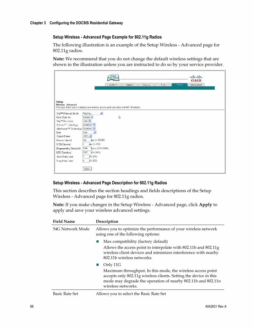
Chapter 3 Configuring the DOCSIS Residential Gateway
88 4042831 Rev A
Setup Wireless - Advanced Page Example for 802.11g Radios
The following illustration is an example of the Setup Wireless - Advanced page for 802.11g radios.
Note: We recommend that you do not change the default wireless settings that are shown in the illustration unless you are instructed to do so by your service provider.
Setup Wireless - Advanced Page Description for 802.11g Radios
This section describes the section headings and fields descriptions of the Setup Wireless - Advanced page for 802.11g radios.
Note: If you make changes in the Setup Wireless - Advanced page, click Apply to apply and save your wireless advanced settings.
Field Name Description
54G Network Mode Allows you to optimize the performance of your wireless network using one of the following options:
Max compatibility (factory default)
Allows the access point to interpolate with 802.11b and 802.11g wireless client devices and minimizes interference with nearby 802.11b wireless networks.
Only 11G
Maximum throughput. In this mode, the wireless access point accepts only 802.11g wireless clients. Setting the device in this mode may degrade the operation of nearby 802.11b and 802.11n wireless networks.
Basic Rate Set Allows you to select the Basic Rate Set
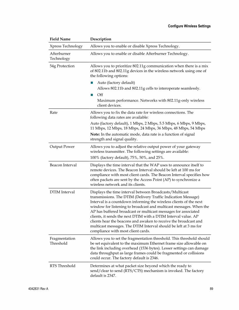
Configure Wireless Settings
4042831 Rev A 89
Field Name Description
Xpress Technology Allows you to enable or disable Xpress Technology.
Afterburner Technology
Allows you to enable or disable Afterburner Technology.
54g Protection Allows you to prioritize 802.11g communication when there is a mix of 802.11b and 802.11g devices in the wireless network using one of the following options:
Auto (factory default)
Allows 802.11b and 802.11g cells to interoperate seamlessly.
Off
Maximum performance. Networks with 802.11g-only wireless client devices.
Rate Allows you to fix the data rate for wireless connections. The following data rates are available:
Auto (factory default), 1 Mbps, 2 Mbps, 5.5 Mbps, 6 Mbps, 9 Mbps, 11 Mbps, 12 Mbps, 18 Mbps, 24 Mbps, 36 Mbps, 48 Mbps, 54 Mbps
Note: In the automatic mode, data rate is a function of signal strength and signal quality.
Output Power Allows you to adjust the relative output power of your gateway wireless transmitter. The following settings are available:
100% (factory default), 75%, 50%, and 25%.
Beacon Interval Displays the time interval that the WAP uses to announce itself to remote devices. The Beacon Interval should be left at 100 ms for compliance with most client cards. The Beacon Interval specifies how often packets are sent by the Access Point (AP) to synchronize a wireless network and its clients.
DTIM Interval Displays the time interval between Broadcasts/Multicast transmissions. The DTIM (Delivery Traffic Indication Message) Interval is a countdown informing the wireless clients of the next window for listening to broadcast and multicast messages. When the AP has buffered broadcast or multicast messages for associated clients, it sends the next DTIM with a DTIM Interval value. AP clients hear the beacons and awaken to receive the broadcast and multicast messages. The DTIM Interval should be left at 3 ms for compliance with most client cards.
Fragmentation Threshold
Allows you to set the fragmentation threshold. This threshold should be set equivalent to the maximum Ethernet frame size allowable on the link including overhead (1536 bytes). Lesser settings can damage data throughput as large frames could be fragmented or collisions could occur. The factory default is 2346.
RTS Threshold Determines at what packet size beyond which the ready to send/clear to send (RTS/CTS) mechanism is invoked. The factory default is 2347.
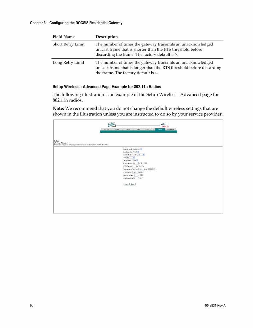
Chapter 3 Configuring the DOCSIS Residential Gateway
90 4042831 Rev A
Field Name Description
Short Retry Limit The number of times the gateway transmits an unacknowledged unicast frame that is shorter than the RTS threshold before discarding the frame. The factory default is 7.
Long Retry Limit The number of times the gateway transmits an unacknowledged unicast frame that is longer than the RTS threshold before discarding the frame. The factory default is 4.
Setup Wireless - Advanced Page Example for 802.11n Radios
The following illustration is an example of the Setup Wireless - Advanced page for 802.11n radios.
Note: We recommend that you do not change the default wireless settings that are shown in the illustration unless you are instructed to do so by your service provider.
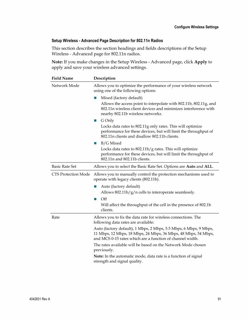
Configure Wireless Settings
4042831 Rev A 91
Setup Wireless - Advanced Page Description for 802.11n Radios
This section describes the section headings and fields descriptions of the Setup Wireless - Advanced page for 802.11n radios.
Note: If you make changes in the Setup Wireless - Advanced page, click Apply to apply and save your wireless advanced settings.
Field Name Description
Network Mode Allows you to optimize the performance of your wireless network using one of the following options:
Mixed (factory default)
Allows the access point to interpolate with 802.11b, 802.11g, and 802.11n wireless client devices and minimizes interference with nearby 802.11b wireless networks.
G Only
Locks data rates to 802.11g only rates. This will optimize performance for these devices, but will limit the throughput of 802.11n clients and disallow 802.11b clients.
B/G Mixed
Locks data rates to 802.11b/g rates. This will optimize performance for these devices, but will limit the throughput of 802.11n and 802.11b clients.
Basic Rate Set Allows you to select the Basic Rate Set. Options are Auto and ALL.
CTS Protection Mode Allows you to manually control the protection mechanisms used to operate with legacy clients (802.11b).
Auto (factory default)
Allows 802.11b/g/n cells to interoperate seamlessly.
Off
Will affect the throughput of the cell in the presence of 802.1b clients.
Rate Allows you to fix the data rate for wireless connections. The following data rates are available:
Auto (factory default), 1 Mbps, 2 Mbps, 5.5 Mbps, 6 Mbps, 9 Mbps, 11 Mbps, 12 Mbps, 18 Mbps, 24 Mbps, 36 Mbps, 48 Mbps, 54 Mbps, and MCS 0-15 rates which are a function of channel width.
The rates available will be based on the Network Mode chosen previously.
Note: In the automatic mode, data rate is a function of signal strength and signal quality.
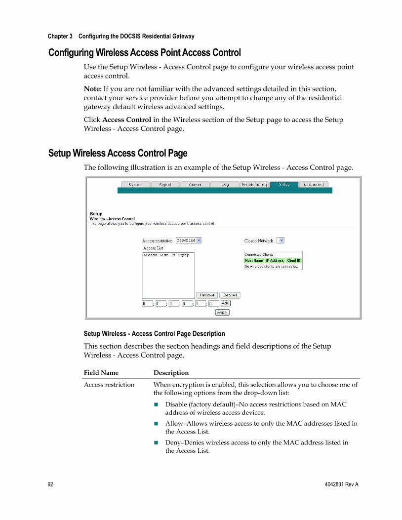
Chapter 3 Configuring the DOCSIS Residential Gateway
92 4042831 Rev A
Configuring Wireless Access Point Access Control
Use the Setup Wireless - Access Control page to configure your wireless access point access control.
Note: If you are not familiar with the advanced settings detailed in this section, contact your service provider before you attempt to change any of the residential gateway default wireless advanced settings.
Click Access Control in the Wireless section of the Setup page to access the Setup Wireless - Access Control page.
Setup Wireless Access Control Page
The following illustration is an example of the Setup Wireless - Access Control page.
Setup Wireless - Access Control Page Description
This section describes the section headings and field descriptions of the Setup Wireless - Access Control page.
Field Name Description
Access restriction When encryption is enabled, this selection allows you to choose one of the following options from the drop-down list:
Disable (factory default)–No access restrictions based on MAC address of wireless access devices.
Allow–Allows wireless access to only the MAC addresses listed in the Access List.
Deny–Denies wireless access to only the MAC address listed in the Access List.
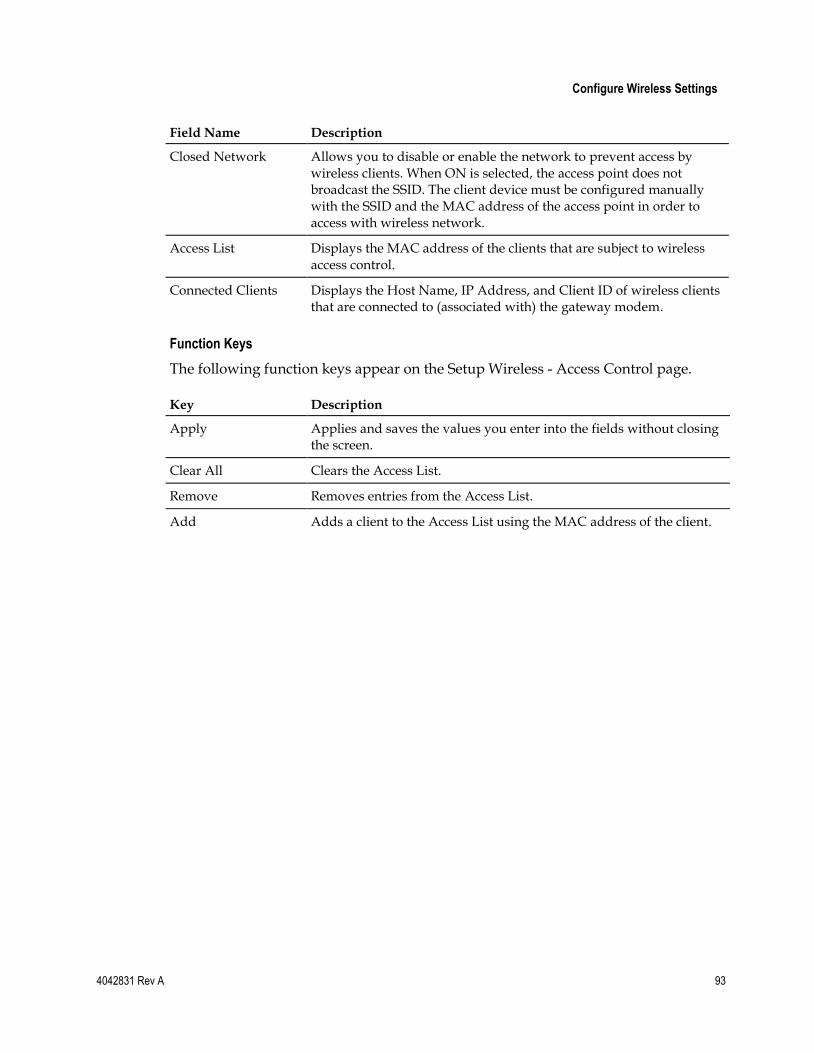
Configure Wireless Settings
4042831 Rev A 93
Field Name Description
Closed Network Allows you to disable or enable the network to prevent access by wireless clients. When ON is selected, the access point does not broadcast the SSID. The client device must be configured manually with the SSID and the MAC address of the access point in order to access with wireless network.
Access List Displays the MAC address of the clients that are subject to wireless access control.
Connected Clients Displays the Host Name, IP Address, and Client ID of wireless clients that are connected to (associated with) the gateway modem.
Function Keys
The following function keys appear on the Setup Wireless - Access Control page.
Key Description
Apply Applies and saves the values you enter into the fields without closing the screen.
Clear All Clears the Access List.
Remove Removes entries from the Access List.
Add Adds a client to the Access List using the MAC address of the client.
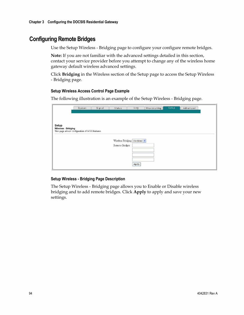
Chapter 3 Configuring the DOCSIS Residential Gateway
94 4042831 Rev A
Configuring Remote Bridges
Use the Setup Wireless - Bridging page to configure your configure remote bridges.
Note: If you are not familiar with the advanced settings detailed in this section, contact your service provider before you attempt to change any of the wireless home gateway default wireless advanced settings.
Click Bridging in the Wireless section of the Setup page to access the Setup Wireless - Bridging page.
Setup Wireless Access Control Page Example
The following illustration is an example of the Setup Wireless - Bridging page.
Setup Wireless - Bridging Page Description
The Setup Wireless - Bridging page allows you to Enable or Disable wireless bridging and to add remote bridges. Click Apply to apply and save your new settings.
4042831 Rev A 95
Introduction
This section describes the behavior of the front panel indicators when the residential gateway is first powered up, during normal operations, and in special conditions.
4 Chapter 4 Operation of Front Panel Indicators
In This Chapter
Initial Power Up, Calibration, and Registration (AC Power applied) .................................................................................................. 96
Normal Operations (AC Power Applied) ......................................... 97
Special Conditions ................................................................................ 98
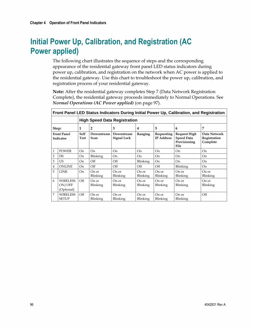
Chapter 4 Operation of Front Panel Indicators
96 4042831 Rev A
Initial Power Up, Calibration, and Registration (AC Power applied)
The following chart illustrates the sequence of steps and the corresponding appearance of the residential gateway front panel LED status indicators during power up, calibration, and registration on the network when AC power is applied to the residential gateway. Use this chart to troubleshoot the power up, calibration, and registration process of your residential gateway.
Note: After the residential gateway completes Step 7 (Data Network Registration Complete), the residential gateway proceeds immediately to Normal Operations. See Normal Operations (AC Power applied) (on page 97).
Front Panel LED Status Indicators During Initial Power Up, Calibration, and Registration
High Speed Data Registration
Step: 1 2 3 4 5 6 7
Front Panel
Indicator
Self Test
Downstream Scan
Downstream Signal Lock
Ranging Requesting IP Address
Request High Speed Data Provisioning File
Data Network Registration Complete
1 POWER On On On On On On On
2 DS On Blinking On On On On On
3 US On Off Off Blinking On On On
4 ONLINE On Off Off Off Off Blinking On
5 LINK On On or Blinking
On or Blinking
On or Blinking
On or Blinking
On or Blinking
On or Blinking
6 WIRELESS ON/OFF
(Optional)
Off On or Blinking
On or Blinking
On or Blinking
On or Blinking
On or Blinking
On or Blinking
7 WIRELESS SETUP
Off On or Blinking
On or Blinking
On or Blinking
On or Blinking
On or Blinking
Off
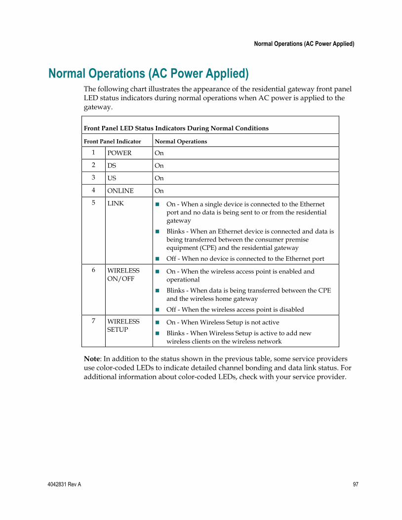
Normal Operations (AC Power Applied)
4042831 Rev A 97
Normal Operations (AC Power Applied) The following chart illustrates the appearance of the residential gateway front panel LED status indicators during normal operations when AC power is applied to the gateway.
Front Panel LED Status Indicators During Normal Conditions
Front Panel Indicator Normal Operations
1 POWER On
2 DS On
3 US On
4 ONLINE On
5 LINK On - When a single device is connected to the Ethernet port and no data is being sent to or from the residential gateway
Blinks - When an Ethernet device is connected and data is being transferred between the consumer premise equipment (CPE) and the residential gateway
Off - When no device is connected to the Ethernet port
6 WIRELESS ON/OFF
On - When the wireless access point is enabled and operational
Blinks - When data is being transferred between the CPE and the wireless home gateway
Off - When the wireless access point is disabled
7 WIRELESS SETUP
On - When Wireless Setup is not active
Blinks - When Wireless Setup is active to add new wireless clients on the wireless network
Note: In addition to the status shown in the previous table, some service providers use color-coded LEDs to indicate detailed channel bonding and data link status. For additional information about color-coded LEDs, check with your service provider.
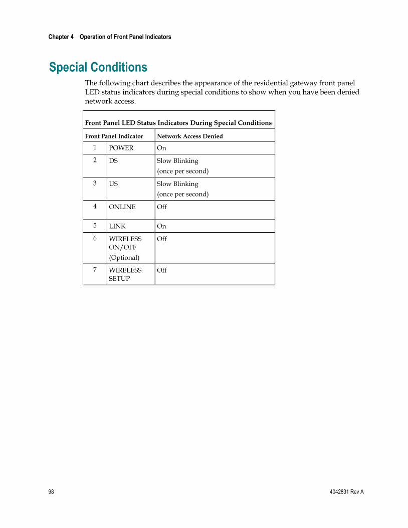
Chapter 4 Operation of Front Panel Indicators
98 4042831 Rev A
Special Conditions The following chart describes the appearance of the residential gateway front panel LED status indicators during special conditions to show when you have been denied network access.
Front Panel LED Status Indicators During Special Conditions
Front Panel Indicator Network Access Denied
1 POWER On
2 DS Slow Blinking
(once per second)
3 US Slow Blinking
(once per second)
4 ONLINE Off
5 LINK On
6 WIRELESS ON/OFF
(Optional)
Off
7 WIRELESS SETUP
Off
4042831 Rev A 99
Introduction
This chapter describes the most common issues that may occur after the residential gateway is installed and provides possible solutions and tips for improved performance of the residential gateway.
5 Chapter 5 Troubleshooting the DOCSIS Residential Gateway
In This Chapter
Frequently Asked Questions ............................................................. 100
Common Troubleshooting Issues ..................................................... 105
Tips for Improved Performance ....................................................... 106
Chapter 5 Troubleshooting the DOCSIS Residential Gateway
100 4042831 Rev A
Frequently Asked Questions This section provides answers to common questions about the residential gateway.
How Do I Configure TCP/IP Protocol?
To configure TCP/IP protocol, you need to have an Ethernet Network Interface Card (NIC) with TCP/IP communications protocol installed on your system. TCP/IP is a communications protocol used to access the Internet. This section contains instructions for configuring TCP/IP on your Internet devices to operate with the residential gateway in Microsoft Windows or Macintosh environments.
TCP/IP protocol in a Microsoft Windows environment is different for each operating system. Follow the appropriate instructions in this section for your operating system.
Configuring TCP/IP on Windows 7 Systems
1 Open Network Connections by clicking the Start button, and then clicking Control Panel.
2 In the Search box, type adapter, and then, under Network and Sharing Center, click View network connections.
3 Right-click the connection that you want to change, and then click Properties. If you are prompted for an administrator password or confirmation, type the password or provide confirmation. The Local Area Connection Properties window opens.
4 Click the Networking tab.
5 Under This connection uses the following items, click either Internet Protocol Version 4 (TCP/IPv4) or Internet Protocol Version 6 (TCP/IPv6), and then click Properties.
6 To specify IPv4 IP address settings, do one of the following:
To get IP settings automatically using DHCP, click Obtain an IP address
automatically, and then click OK.
To specify an IP address, click Use the following IP address, and then, in the IP address, Subnet mask, and Default gateway boxes, type the IP address settings.
7 To specify IPv6 IP address settings, do one of the following:
To get IP settings automatically using DHCP, click Obtain an IPv6 address automatically, and then click OK.
To specify an IP address, click Use the following IPv6 address, and then, in the IPv6 address, Subnet prefix length, and the Default gateway boxes, type the IP address settings.
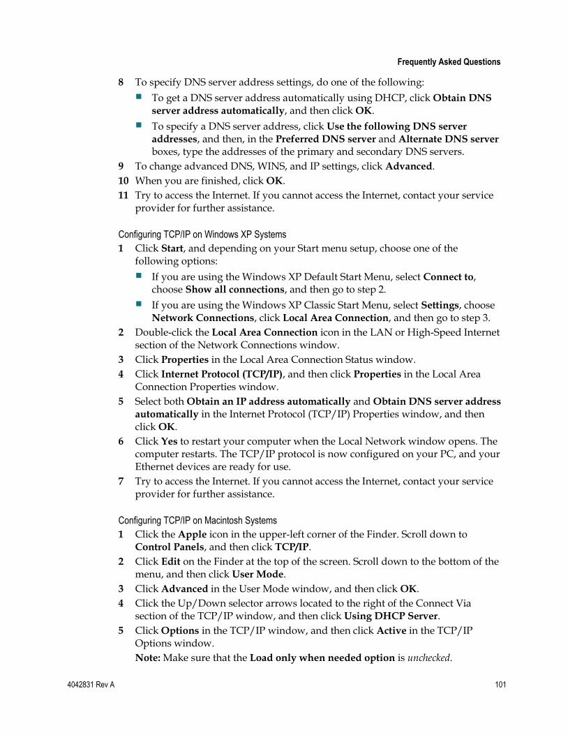
Frequently Asked Questions
4042831 Rev A 101
8 To specify DNS server address settings, do one of the following:
To get a DNS server address automatically using DHCP, click Obtain DNS
server address automatically, and then click OK.
To specify a DNS server address, click Use the following DNS server
addresses, and then, in the Preferred DNS server and Alternate DNS server boxes, type the addresses of the primary and secondary DNS servers.
9 To change advanced DNS, WINS, and IP settings, click Advanced.
10 When you are finished, click OK.
11 Try to access the Internet. If you cannot access the Internet, contact your service provider for further assistance.
Configuring TCP/IP on Windows XP Systems
1 Click Start, and depending on your Start menu setup, choose one of the following options:
If you are using the Windows XP Default Start Menu, select Connect to, choose Show all connections, and then go to step 2.
If you are using the Windows XP Classic Start Menu, select Settings, choose Network Connections, click Local Area Connection, and then go to step 3.
2 Double-click the Local Area Connection icon in the LAN or High-Speed Internet section of the Network Connections window.
3 Click Properties in the Local Area Connection Status window.
4 Click Internet Protocol (TCP/IP), and then click Properties in the Local Area Connection Properties window.
5 Select both Obtain an IP address automatically and Obtain DNS server address
automatically in the Internet Protocol (TCP/IP) Properties window, and then click OK.
6 Click Yes to restart your computer when the Local Network window opens. The computer restarts. The TCP/IP protocol is now configured on your PC, and your Ethernet devices are ready for use.
7 Try to access the Internet. If you cannot access the Internet, contact your service provider for further assistance.
Configuring TCP/IP on Macintosh Systems
1 Click the Apple icon in the upper-left corner of the Finder. Scroll down to Control Panels, and then click TCP/IP.
2 Click Edit on the Finder at the top of the screen. Scroll down to the bottom of the menu, and then click User Mode.
3 Click Advanced in the User Mode window, and then click OK.
4 Click the Up/Down selector arrows located to the right of the Connect Via section of the TCP/IP window, and then click Using DHCP Server.
5 Click Options in the TCP/IP window, and then click Active in the TCP/IP Options window.
Note: Make sure that the Load only when needed option is unchecked.
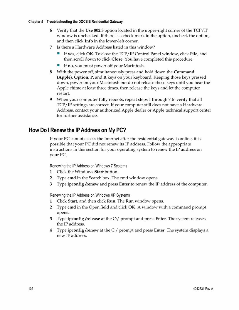
Chapter 5 Troubleshooting the DOCSIS Residential Gateway
102 4042831 Rev A
6 Verify that the Use 802.3 option located in the upper-right corner of the TCP/IP window is unchecked. If there is a check mark in the option, uncheck the option, and then click Info in the lower-left corner.
7 Is there a Hardware Address listed in this window?
If yes, click OK. To close the TCP/IP Control Panel window, click File, and then scroll down to click Close. You have completed this procedure.
If no, you must power off your Macintosh.
8 With the power off, simultaneously press and hold down the Command (Apple), Option, P, and R keys on your keyboard. Keeping those keys pressed down, power on your Macintosh but do not release these keys until you hear the Apple chime at least three times, then release the keys and let the computer restart.
9 When your computer fully reboots, repeat steps 1 through 7 to verify that all TCP/IP settings are correct. If your computer still does not have a Hardware Address, contact your authorized Apple dealer or Apple technical support center for further assistance.
How Do I Renew the IP Address on My PC?
If your PC cannot access the Internet after the residential gateway is online, it is possible that your PC did not renew its IP address. Follow the appropriate instructions in this section for your operating system to renew the IP address on your PC.
Renewing the IP Address on Windows 7 Systems
1 Click the Windows Start button.
2 Type cmd in the Search box. The cmd window opens.
3 Type ipconfig /renew and press Enter to renew the IP address of the computer.
Renewing the IP Address on Windows XP Systems
1 Click Start, and then click Run. The Run window opens.
2 Type cmd in the Open field and click OK. A window with a command prompt opens.
3 Type ipconfig /release at the C:/ prompt and press Enter. The system releases the IP address.
4 Type ipconfig /renew at the C:/ prompt and press Enter. The system displays a new IP address.
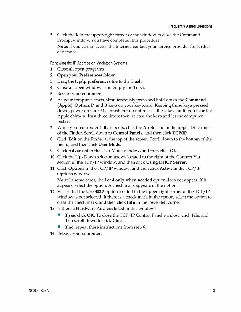
Frequently Asked Questions
4042831 Rev A 103
5 Click the X in the upper-right corner of the window to close the Command Prompt window. You have completed this procedure.
Note: If you cannot access the Internet, contact your service provider for further assistance.
Renewing the IP Address on Macintosh Systems
1 Close all open programs.
2 Open your Preferences folder.
3 Drag the tcp/ip preferences file to the Trash.
4 Close all open windows and empty the Trash.
5 Restart your computer.
6 As your computer starts, simultaneously press and hold down the Command
(Apple), Option, P, and R keys on your keyboard. Keeping those keys pressed down, power on your Macintosh but do not release these keys until you hear the Apple chime at least three times; then, release the keys and let the computer restart.
7 When your computer fully reboots, click the Apple icon in the upper-left corner of the Finder. Scroll down to Control Panels, and then click TCP/IP.
8 Click Edit on the Finder at the top of the screen. Scroll down to the bottom of the menu, and then click User Mode.
9 Click Advanced in the User Mode window, and then click OK.
10 Click the Up/Down selector arrows located to the right of the Connect Via section of the TCP/IP window, and then click Using DHCP Server.
11 Click Options in the TCP/IP window, and then click Active in the TCP/IP Options window.
Note: In some cases, the Load only when needed option does not appear. If it appears, select the option. A check mark appears in the option.
12 Verify that the Use 802.3 option located in the upper-right corner of the TCP/IP window is not selected. If there is a check mark in the option, select the option to clear the check mark, and then click Info in the lower-left corner.
13 Is there a Hardware Address listed in this window?
If yes, click OK. To close the TCP/IP Control Panel window, click File, and then scroll down to click Close.
If no, repeat these instructions from step 6.
14 Reboot your computer.
Chapter 5 Troubleshooting the DOCSIS Residential Gateway
104 4042831 Rev A
What if I Don't Subscribe to Cable TV?
If cable TV is available in your area, data service may be made available with or without subscribing to cable TV service. Contact your local service provider for complete information on cable services, including high-speed Internet access.
How Do I Arrange for Installation?
Call your service provider to inquire about professional installation. A professional installation ensures proper cable connection to the residential gateway and to your PC, and it ensures the proper configuration of all hardware and software settings. Contact your service provider for more information about installation.
How Does the Residential Gateway Connect to My Computer?
The residential gateway connects to the 10/100BASE-T Ethernet port on your PC. To use the Ethernet interface, Ethernet cards available from your local PC or office supply retailer, or from your service provider. For best performance over an Ethernet connection, your PC should be equipped with a Gigabit Ethernet card.
After My Residential Gateway Is Connected, How Do I Access the Internet?
Your local service provider becomes your Internet Service Provider (ISP). They offer a wide range of services including e-mail, chat, news, and information services. Your service provider will provide the software you will need.
Can I Watch TV and Surf the Internet at the Same Time?
Absolutely! If you subscribe to cable television service, you can watch TV and use your residential gateway at the same time by connecting your TV and your residential gateway to the cable network using an optional cable signal splitter.
Common Troubleshooting Issues
4042831 Rev A 105
Common Troubleshooting Issues This section describes common problems and offers solutions.
I don't understand the front panel status indicators
See Operation of Front Panel Indicators (on page 95), for more detailed information on front panel LED status indicator operation and function.
The Residential Gateway does not register an Ethernet connection
Try one of the following solutions:
Verify that your computer has an Ethernet card and that the Ethernet driver software is properly installed. If you purchase and install an Ethernet card, follow the installation instructions very carefully.
Verify the status of the front panel status indicator lights.
The Residential Gateway does not register an Ethernet connection after connecting to a hub
If you are connecting multiple PCs to the residential gateway, you should first connect the residential gateway to the uplink port of the hub using the correct crossover cable. The LINK LED of the hub will illuminate continuously.
The Residential Gateway does not register a cable connection
The residential gateway works with a standard, 75-ohm, RF coaxial cable. If you are using a different cable, your residential gateway will not function properly. Contact your service provider to determine whether you are using the correct cable.
Chapter 5 Troubleshooting the DOCSIS Residential Gateway
106 4042831 Rev A
Tips for Improved Performance If your residential gateway does not perform as expected, the following tips may help. If you need further assistance, contact your service provider.
Verify that the plug to your residential gateway AC power is properly inserted into an electrical outlet.
Verify that your residential gateway AC power cord is not plugged into an electrical outlet that is controlled by a wall switch. If a wall switch controls the electrical outlet, make sure the switch is in the ON position.
Verify that the ONLINE LED status indicator on the front panel of your residential gateway is illuminated.
Verify that your cable service is active and that it supports two-way service.
Verify that all cables are properly connected, and that you are using the correct cables.
If you are using the Ethernet connection, verify that your TCP/IP is properly installed and configured.
Verify that you have called your service provider and given them the serial number and MAC address of your residential gateway.
If you are using a cable signal splitter so that you can connect the residential gateway to other devices, remove the splitter and reconnect the cables so that the residential gateway is connected directly to the cable input. If the residential gateway now functions properly, the cable signal splitter may be defective and may need to be replaced.
If you are connected to your PC with an Ethernet connection, your PC should be equipped with a Gigabit Ethernet card for best performance.
If your residential gateway has a USB port and you are connected to that port, verify that you have followed the procedures in Install USB Drivers on Your PC (Optional).
4042831 Rev A 107
Introduction
If you have technical questions, call Cisco Services for assistance. Follow the menu options to speak with a service engineer.
Access your company's extranet site to view or order additional technical publications. For accessing instructions, contact the representative who handles your account. Check your extranet site often as the information is updated frequently.
6 Chapter 6 Customer Information

4042831 Rev A 109
A
accessing the Internet • 104
accessories • 3
advanced settings • 40
C
cable service • 104
connections
description of • 5
how to connect • 14
to computer • 104
D
default network settings • 29
DMZ Host settings • 49
Dynamic DNS settings • 38
E
Ethernet • 105
exposure to moisture • vi
F
features, product • 2
filters, IP address • 42
filters, MAC address • 43
firewall event logging • 67
Firewall settings • 62
Fixed CPE IP Assignment settings • 35
I
indicators
behavior • 96, 97, 98
described • 4
operation of • 95
installation
professional • 104
installation requirements
minimum system requirements • 8
ventilation • vi
Internet
how to access • 104
surfing while watching TV • 104
unable to access • 102
IP address filters • 42
IP address, renewing • 102
L
LAN IP ad • 30
LEDs • 4, 96, 97, 98
location
selecting • vi, 10
M
MAC address filters • 43
N
Network Configuration settings • 29
Network Time protocol • 28
O
overview
power switch • 5
product • 2
WebWizard • 17
P
Parental Control settings • 69, 72, 75, 76
password • 26
performance, tips to improve • 106
port filtering • 45
Port Forwarding settings • 45
product
accessories • 3
features • 2
overview • 2
R
restarting • 36
Index
Index
110 4042831 Rev A
S
safety instructions • v
ground product • v
save configuration to local PC • 37
save configuration to server • 59
Setup • 22
system requirements • 8
T
TCP port filtering • 44
TCP/IP
configuring for Macintosh systems • 101
configuring for Windows XP • 101
time synchronization • 28
troubleshooting • 99
U
UDP port filtering • 44
unpacking • 3
USB • 3, 104
V
ventilation requirements • vi
Voice settings
LEDs • 4, 96, 97, 98
VPN Termination settings • 50
VPN Tunnel settings • 53
W
wall mounting
instructions • 12
slots • 12
WebWizard
logging in • 18
overview • 18
password • 26
Wireless Access Control settings • 92
Wireless Bridging settings • 94
Wireless Security settings • 80

Cisco Systems, Inc. 5030 Sugarloaf Parkway, Box 465447 Lawrenceville, GA 30042
678 277-1120 800 722-2009
www.cisco.com
This document includes various trademarks of Cisco Systems, Inc. Please see the Notices section of this document for a list of the Cisco Systems, Inc. trademarks used in this document. Product and service availability are subject to change without notice.
© 2011 Cisco and/or its affiliates. All rights reserved. October 2011 Printed in USA
Part Number 4042831 Rev A