cisco beacon point module hardware installation guide · chapter 1 cisco beacon point module •...
TRANSCRIPT

Cisco Beacon Point Module —Hardware Installation GuideFirst Published: 2017-11-03
Americas HeadquartersCisco Systems, Inc.170 West Tasman DriveSan Jose, CA 95134-1706USAhttp://www.cisco.comTel: 408 526-4000 800 553-NETS (6387)Fax: 408 527-0883
THE SPECIFICATIONS AND INFORMATION REGARDING THE PRODUCTS IN THIS MANUAL ARE SUBJECT TO CHANGE WITHOUT NOTICE. ALL STATEMENTS,INFORMATION, AND RECOMMENDATIONS IN THIS MANUAL ARE BELIEVED TO BE ACCURATE BUT ARE PRESENTED WITHOUT WARRANTY OF ANY KIND,EXPRESS OR IMPLIED. USERS MUST TAKE FULL RESPONSIBILITY FOR THEIR APPLICATION OF ANY PRODUCTS.
THE SOFTWARE LICENSE AND LIMITEDWARRANTY FOR THE ACCOMPANYING PRODUCT ARE SET FORTH IN THE INFORMATION PACKET THAT SHIPPED WITHTHE PRODUCT AND ARE INCORPORATED HEREIN BY THIS REFERENCE. IF YOU ARE UNABLE TO LOCATE THE SOFTWARE LICENSE OR LIMITED WARRANTY,CONTACT YOUR CISCO REPRESENTATIVE FOR A COPY.
The Cisco implementation of TCP header compression is an adaptation of a program developed by the University of California, Berkeley (UCB) as part of UCB's public domain versionof the UNIX operating system. All rights reserved. Copyright © 1981, Regents of the University of California.
NOTWITHSTANDINGANYOTHERWARRANTYHEREIN, ALL DOCUMENT FILES AND SOFTWARE OF THESE SUPPLIERS ARE PROVIDED “AS IS"WITH ALL FAULTS.CISCO AND THE ABOVE-NAMED SUPPLIERS DISCLAIM ALL WARRANTIES, EXPRESSED OR IMPLIED, INCLUDING, WITHOUT LIMITATION, THOSE OFMERCHANTABILITY, FITNESS FORA PARTICULAR PURPOSEANDNONINFRINGEMENTORARISING FROMACOURSEOFDEALING, USAGE, OR TRADE PRACTICE.
IN NO EVENT SHALL CISCO OR ITS SUPPLIERS BE LIABLE FOR ANY INDIRECT, SPECIAL, CONSEQUENTIAL, OR INCIDENTAL DAMAGES, INCLUDING, WITHOUTLIMITATION, LOST PROFITS OR LOSS OR DAMAGE TO DATA ARISING OUT OF THE USE OR INABILITY TO USE THIS MANUAL, EVEN IF CISCO OR ITS SUPPLIERSHAVE BEEN ADVISED OF THE POSSIBILITY OF SUCH DAMAGES.
Any Internet Protocol (IP) addresses and phone numbers used in this document are not intended to be actual addresses and phone numbers. Any examples, command display output, networktopology diagrams, and other figures included in the document are shown for illustrative purposes only. Any use of actual IP addresses or phone numbers in illustrative content is unintentionaland coincidental.
Cisco and the Cisco logo are trademarks or registered trademarks of Cisco and/or its affiliates in the U.S. and other countries. To view a list of Cisco trademarks, go to this URL: http://www.cisco.com/go/trademarks. Third-party trademarks mentioned are the property of their respective owners. The use of the word partner does not imply a partnershiprelationship between Cisco and any other company. (1110R)
© 2017 Cisco Systems, Inc. All rights reserved.
C O N T E N T S
P r e f a c e Preface v
Audience v
Conventions v
Related Documentation vi
Obtaining Documentation and Submitting a Service Request vi
C H A P T E R 1 Cisco Beacon Point Module 1
Overview of Cisco Beacon Point Module 1
About Cisco Beacon Point Module 1
Cisco Beacon Point Module Features 3
Technical Specifications 3
Cisco Beacon Point Module Model Number 4
Installing a Cisco Beacon Point 4
Unpacking the Cisco Beacon Point Module 4
Attaching Locking lever to AIR-AP-BRACKET-2 6
Installing Cisco Beacon Point Module and APs Separately 7
Installing the Cisco Beacon Point Module to the AP and Mounting as a Combined Unit 9
Uninstalling Cisco Beacon Point Module 11
Cisco Beacon Point Module LEDs 12
C H A P T E R 2 Declarations of Conformity and Regulatory Information 15
Manufacturers Federal Communication Commission Declaration of Conformity Statement 16
VCCI Statement for Japan 17
Guidelines for Operating Cisco Virtual Beacon in Japan 17
Japanese Translation 17
English Translation 17
Canadian Compliance Statement 18
Cisco Beacon Point Module —Hardware Installation Guide iii

Statement 371—Power Cable and Power Injector 19
Industry Canada 19
This Device Meets FCC and International Guidelines for Exposure to Radio Waves 19
This Device Meets the Industry Canada Guidelines for Exposure to Radio Waves 20
Cet appareil est conforme aux directives internationales en matière d'exposition aux fréquences
radioélectriques 20
Additional Information on RF Exposure 21
Declaration of Conformity Statements 21
Cisco Beacon Point Module —Hardware Installation Guideiv
Contents
Preface
• Audience, page v
• Conventions, page v
• Related Documentation, page vi
• Obtaining Documentation and Submitting a Service Request, page vi
AudienceThis document is for ConnectedMobile Experiences (CMX) network and IT administrators who deploy CiscoBeacon Point (BP) or Cisco Beacon Point Module (BPM) for high accuracy virtual beacon solution.
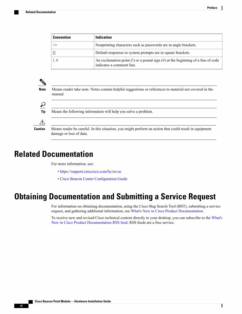
ConventionsThis document uses the following conventions:
Table 1: Conventions
IndicationConvention
Commands and keywords and user-entered text appear in bold font.bold font
Document titles, new or emphasized terms, and arguments for which you supplyvalues are in italic font.
italic font
Elements in square brackets are optional.[ ]
Required alternative keywords are grouped in braces and separated by verticalbars.
{x | y | z }
Optional alternative keywords are grouped in brackets and separated by verticalbars.
[ x | y | z ]
A nonquoted set of characters. Do not use quotation marks around the string.Otherwise, the string will include the quotation marks.
string
Terminal sessions and information the system displays appear in courier font.courier font
Cisco Beacon Point Module —Hardware Installation Guide v
IndicationConvention
Nonprinting characters such as passwords are in angle brackets.<>
Default responses to system prompts are in square brackets.[]
An exclamation point (!) or a pound sign (#) at the beginning of a line of codeindicates a comment line.
!, #
Means reader take note. Notes contain helpful suggestions or references to material not covered in themanual.
Note
Means the following information will help you solve a problem.Tip
Means reader be careful. In this situation, you might perform an action that could result in equipmentdamage or loss of data.
Caution
Related DocumentationFor more information, see:
• https://support.cmxcisco.com/hc/en-us
• Cisco Beacon Center Configuration Guide
Obtaining Documentation and Submitting a Service RequestFor information on obtaining documentation, using the Cisco Bug Search Tool (BST), submitting a servicerequest, and gathering additional information, see What's New in Cisco Product Documentation.
To receive new and revised Cisco technical content directly to your desktop, you can subscribe to the What'sNew in Cisco Product Documentation RSS feed. RSS feeds are a free service.
Cisco Beacon Point Module —Hardware Installation Guidevi
PrefaceRelated Documentation

C H A P T E R 1Cisco Beacon Point Module
• Overview of Cisco Beacon Point Module, page 1
• Installing a Cisco Beacon Point, page 4
Overview of Cisco Beacon Point Module
About Cisco Beacon Point ModuleCisco Beacon Point Module (AIR-RM-VBLE2-K9=) is a Bluetooth Low Energy beacon module that ismounted on supported access points. The APs now has the ability to provide Wi-Fi access as well as act asBLE Beacons for Bluetooth-integrated clients. With Cisco Beacon Point Module, smart client devices canreceive different signal strengths from the multiple integrated beacon to improve location calculations.
Deploying Bluetooth-integrated APs is similar to Wi-Fi location based service solution. The recommendeddensity for deploying the Bluetooth-integrated APs is one per 1500-to-2500 sq.ft. The optimum height for aBluetooth-integrated APs is 13 to 15 ft (3.9 to 4.6m). Cisco Beacon Center requires the correct physicalorientation, position, and height of Bluetooth-integrated APs for providing clients with indoor navigation,turn-by-turn guidance and proximity messaging for best indoor navigation experience.
Bluetooth-integrated APs connect with Cisco Beacon Center over the internet using secure HTTPS protocol.Bluetooth-integrated APs, each have a unique IP address just like any enterprise grade networking device.Bluetooth-integrated APs should connect with Cisco Beacon Center for management and control. For
Cisco Beacon Point Module —Hardware Installation Guide 1
Bluetooth-integrated APs to communicate with the Cisco Beacon Center, outbound communications fromCisco Beacon Point Module to the cloud service using port 80 (TCP) and 443 (TCP) must be possible.
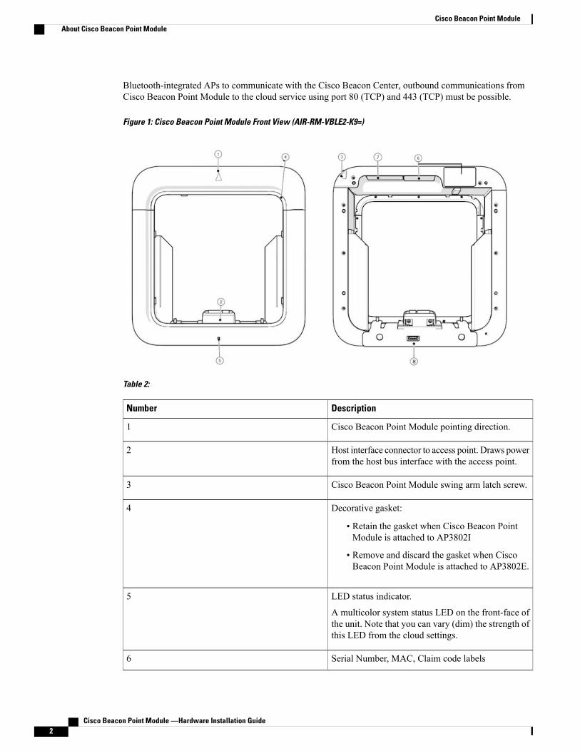
Figure 1: Cisco Beacon Point Module Front View (AIR-RM-VBLE2-K9=)
Table 2:
DescriptionNumber
Cisco Beacon Point Module pointing direction.1
Host interface connector to access point. Draws powerfrom the host bus interface with the access point.
2
Cisco Beacon Point Module swing arm latch screw.3
Decorative gasket:
• Retain the gasket when Cisco Beacon PointModule is attached to AP3802I
• Remove and discard the gasket when CiscoBeacon Point Module is attached to AP3802E.
4
LED status indicator.
A multicolor system status LED on the front-face ofthe unit. Note that you can vary (dim) the strength ofthis LED from the cloud settings.
5
Serial Number, MAC, Claim code labels6
Cisco Beacon Point Module —Hardware Installation Guide2
Cisco Beacon Point ModuleAbout Cisco Beacon Point Module

DescriptionNumber
Regulatory labels7
Console port (covered with mylar label atmanufacturing).
8
Supported Access Points
The Cisco Beacon Point Module can be attached to the following APs:
• AP3802I
• AP3802E
Cisco Beacon Point Module FeaturesCisco Beacon Point Module comes with the following features:
Table 3: Hardware Feature Summary
DescriptionFeature
A multicolor system status LED on the front-face ofthe unit. Note that you can vary (dim) the strength ofthis LED from the cloud settings.
LED indicators
Draws power from the PCIe bus interface with theaccess point.
Power Options
Technical SpecificationsTable 4: Technical Specifications of Cisco Beacon Point Module
DescriptionFeature
285 mm x 275 mm x 61 mm
11.2 in. x 10.8 in. x 2.4 in.
Dimensions (of APs with Cisco Beacon PointModule)
1.4 kg (3.0 lbs)Weight
Cisco Beacon Point Module —Hardware Installation Guide 3
Cisco Beacon Point ModuleCisco Beacon Point Module Features

DescriptionFeature
Fanless operation; passive cooling
Nonoperating (storage) temperature: – 30 to 70℃ (–22 to 158℉)
Operating temperature: 0 to 40℃ (32 to 104℉)
Operating humidity: 10 to 90% (noncondensing)
Operating altitude: 10,000 ft (3048 m)
Environmental
Less than 6 WPower Dissipation
Cisco Beacon Point Module Model NumberCisco Beacon Point Module is available in the following model:
Table 5: Cisco Beacon Point Module Model Number
DescriptionProduct ID
Cisco Beacon Point Module can be mounted onsupported APs.
Note that while the Cisco Beacon Point Module mustbe attached to supported APs, the Cisco Beacon Pointitself is a standalone device.
AIR-RM-VBLE2-K9=
Installing a Cisco Beacon Point
Unpacking the Cisco Beacon Point Module
Step 1 Unpack and remove Cisco Beacon Point Module and accessories from the shipping box.Step 2 Return the packing material to the shipping and save it for future use.Step 3 Record the Serial Number,MAC address and Claim code of the Cisco Beacon PointModule. Youwill need this information
later to claim the Cisco Beacon Point Module from Cisco Beacon Center.Step 4 Verify that you have received the following items. If an item is missing or is damaged, contact your Cisco representative
or reseller for further instructions.
• Cisco Beacon Point Module
Cisco Beacon Point Module —Hardware Installation Guide4
Cisco Beacon Point ModuleCisco Beacon Point Module Model Number
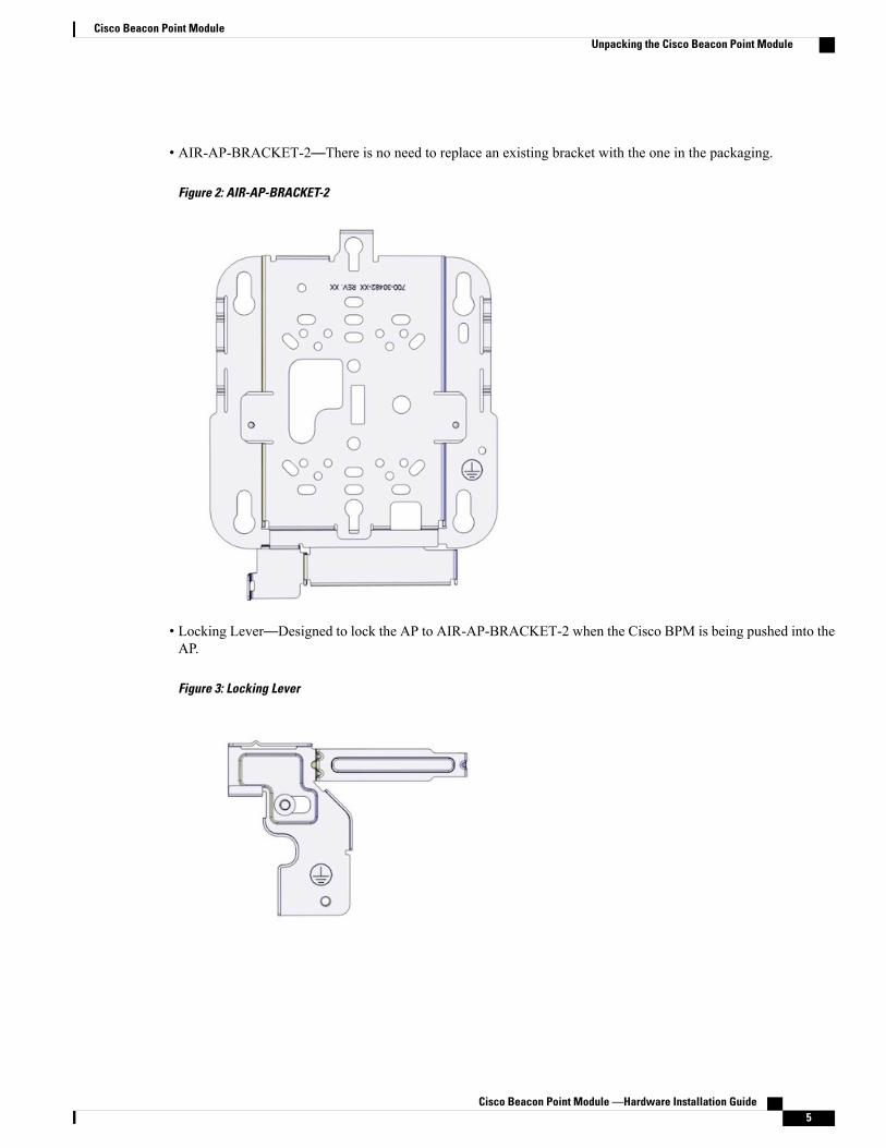
• AIR-AP-BRACKET-2—There is no need to replace an existing bracket with the one in the packaging.
Figure 2: AIR-AP-BRACKET-2
• Locking Lever—Designed to lock the AP to AIR-AP-BRACKET-2 when the Cisco BPM is being pushed into theAP.
Figure 3: Locking Lever
Cisco Beacon Point Module —Hardware Installation Guide 5
Cisco Beacon Point ModuleUnpacking the Cisco Beacon Point Module
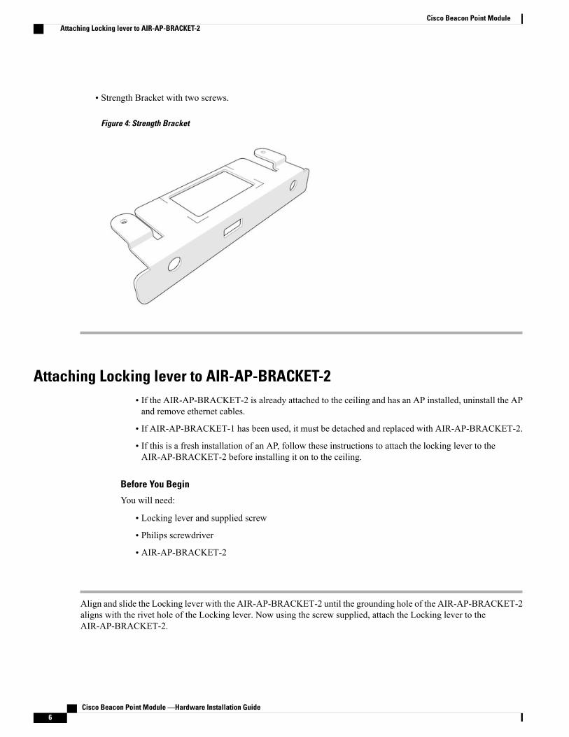
• Strength Bracket with two screws.
Figure 4: Strength Bracket
Attaching Locking lever to AIR-AP-BRACKET-2• If the AIR-AP-BRACKET-2 is already attached to the ceiling and has an AP installed, uninstall the APand remove ethernet cables.
• If AIR-AP-BRACKET-1 has been used, it must be detached and replaced with AIR-AP-BRACKET-2.
• If this is a fresh installation of an AP, follow these instructions to attach the locking lever to theAIR-AP-BRACKET-2 before installing it on to the ceiling.
Before You Begin
You will need:
• Locking lever and supplied screw
• Philips screwdriver
• AIR-AP-BRACKET-2
Align and slide the Locking lever with the AIR-AP-BRACKET-2 until the grounding hole of the AIR-AP-BRACKET-2aligns with the rivet hole of the Locking lever. Now using the screw supplied, attach the Locking lever to theAIR-AP-BRACKET-2.
Cisco Beacon Point Module —Hardware Installation Guide6
Cisco Beacon Point ModuleAttaching Locking lever to AIR-AP-BRACKET-2
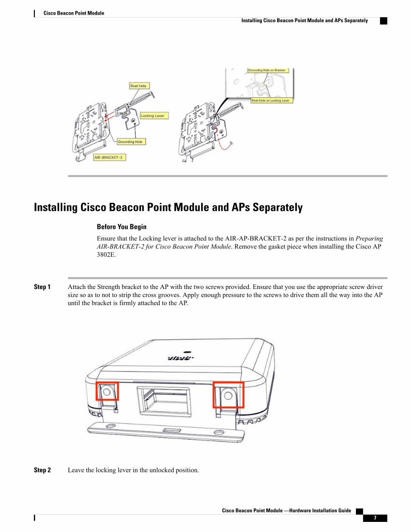
Installing Cisco Beacon Point Module and APs Separately
Before You Begin
Ensure that the Locking lever is attached to the AIR-AP-BRACKET-2 as per the instructions in PreparingAIR-BRACKET-2 for Cisco Beacon Point Module. Remove the gasket piece when installing the Cisco AP3802E.
Step 1 Attach the Strength bracket to the AP with the two screws provided. Ensure that you use the appropriate screw driversize so as to not to strip the cross grooves. Apply enough pressure to the screws to drive them all the way into the APuntil the bracket is firmly attached to the AP.
Step 2 Leave the locking lever in the unlocked position.
Cisco Beacon Point Module —Hardware Installation Guide 7
Cisco Beacon Point ModuleInstalling Cisco Beacon Point Module and APs Separately

Step 3 Now install the AP to the AIR-AP-BRACKET-2 as usual, ensuring that the AP snaps into the four holes of the bracket.Step 4 Push the locking lever into the locked position to secure the unit. This secures and locks the AP in position during the
installation of the Cisco Beacon Point Module in the next step.Step 5 Now install the Cisco Beacon Point Module onto the AP. Loosen the captive screw on the Cisco Beacon Point Module
handle and swing it open clockwise and all the way to the six-o-clock position. Slide the Cisco Beacon Point Moduleon to the AP until it snaps firmly on to the AP bracket, with the two dimples on Cisco Beacon Point Module snappinginto the middle of the two bracket holes.
Cisco Beacon Point Module —Hardware Installation Guide8
Cisco Beacon Point ModuleInstalling Cisco Beacon Point Module and APs Separately

Step 6 Close the hinged door of the Cisco Beacon Point Module.Step 7 Screw in the inset screw on the Cisco Beacon Point Module to secure the hinged door to the rest of the module.Step 8 Claim the Cisco Beacon Point Module on the Cisco Beacon Center. You can observe the orientation of the Cisco Beacon
Point Module on the Cisco Beacon Center. See the Cisco Beacon Center Configuration Guide.
Installing the Cisco Beacon Point Module to the AP and Mounting as aCombined Unit
Before You Begin
Ensure that the Locking lever is attached to the AIR-AP-BRACKET-2 as per the instructions in PreparingAIR-BRACKET-2 for Cisco Beacon Point Module. Remove the gasket piece when installing the Cisco AP3802E.
Step 1 Attach the Strength bracket to the AP with the two screws provided. Ensure that you use the appropriate screw driversize so as to not strip the cross grooves. Apply enough pressure to the screws to drive them all the way into the AP untilthe bracket is firmly attached to the AP.
Cisco Beacon Point Module —Hardware Installation Guide 9
Cisco Beacon Point ModuleInstalling the Cisco Beacon Point Module to the AP and Mounting as a Combined Unit

Step 2 Leave the Locking lever in the unlocked position
Step 3 Now install the Cisco Beacon Point Module onto the unmounted AP. Loosen the captive screw on the Cisco BeaconPoint Module handle and swing it open clockwise and all the way to the six-o-clock position. Slide the Cisco BeaconPoint Module into the AP until it snaps firmly on to the AP bracket, with the two dimples on Cisco Beacon Point Modulesnapping into the middle of the two bracket holes.
Step 4 Close the hinged door of the Cisco Beacon Point Module.
Cisco Beacon Point Module —Hardware Installation Guide10
Cisco Beacon Point ModuleInstalling the Cisco Beacon Point Module to the AP and Mounting as a Combined Unit

Step 5 Screw in the inset screw on the Cisco Beacon Point Module to secure the hinged door to the rest of the module.Step 6 Install the AP (installed with the Cisco BPM) on to the AIR-AP-BRACKET-2 as you would normally do, that is, align
the screws at the base of the AP with the key holes of AIR-AP-BRACKET-2 and slide the AP onto the slots until it snapsinto place.
Step 7 Push in the locking lever into the locked position to secure the unit. This will ensure safety during future unmouting.Step 8 Claim the Cisco Beacon Point Module on the Cisco Beacon Center. You can observe the orientation of the Cisco Beacon
Point Module on the Cisco Beacon Center. See the Cisco Beacon Center Configuration Guide
Uninstalling Cisco Beacon Point Module• To uninstall the AP, unlock the locking lever, and then pull the AP out of the bracket.
• To remove the Cisco Beacon Point Module and keep the AP, ensure that the Locking lever remains inthe locked position.
Cisco Beacon Point Module —Hardware Installation Guide 11
Cisco Beacon Point ModuleUninstalling Cisco Beacon Point Module
Cisco Beacon Point Module LEDs
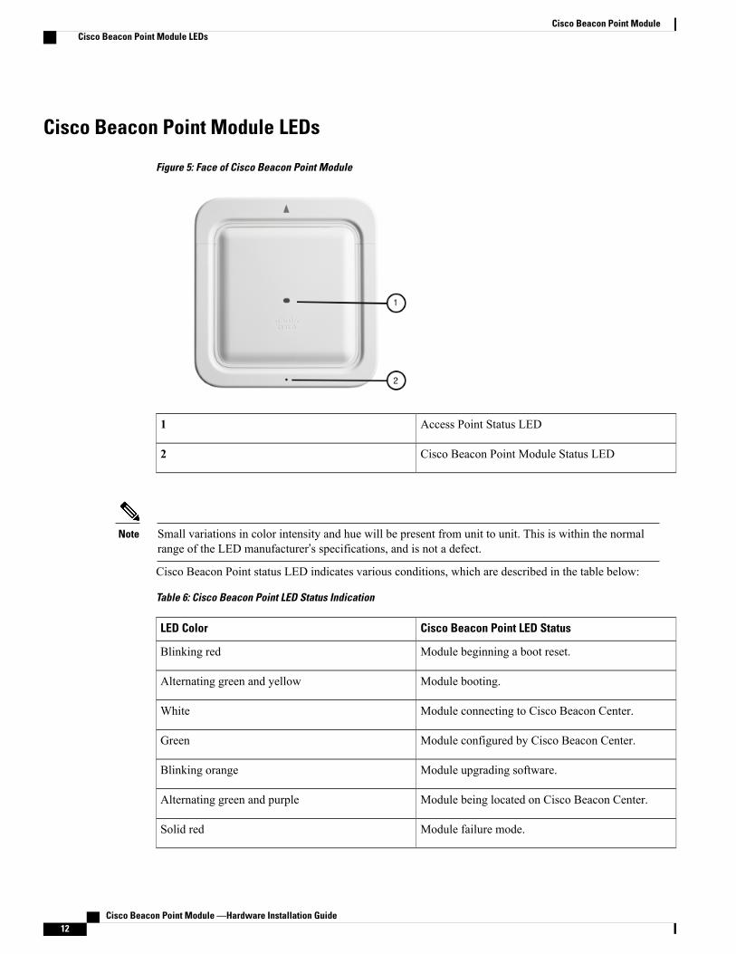
Figure 5: Face of Cisco Beacon Point Module
Access Point Status LED1
Cisco Beacon Point Module Status LED2
Small variations in color intensity and hue will be present from unit to unit. This is within the normalrange of the LED manufacturer’s specifications, and is not a defect.
Note
Cisco Beacon Point status LED indicates various conditions, which are described in the table below:
Table 6: Cisco Beacon Point LED Status Indication
Cisco Beacon Point LED StatusLED Color
Module beginning a boot reset.Blinking red
Module booting.Alternating green and yellow
Module connecting to Cisco Beacon Center.White
Module configured by Cisco Beacon Center.Green
Module upgrading software.Blinking orange
Module being located on Cisco Beacon Center.Alternating green and purple
Module failure mode.Solid red
Cisco Beacon Point Module —Hardware Installation Guide12
Cisco Beacon Point ModuleCisco Beacon Point Module LEDs
Cisco Beacon Point Module —Hardware Installation Guide 13
Cisco Beacon Point ModuleCisco Beacon Point Module LEDs
Cisco Beacon Point Module —Hardware Installation Guide14
Cisco Beacon Point ModuleCisco Beacon Point Module LEDs

C H A P T E R 2Declarations of Conformity and RegulatoryInformation
This chapter provides declarations of conformity and regulatory information for the Cisco Beacon Point.You can find additional information at this location.
• Manufacturers Federal Communication Commission Declaration of Conformity Statement, page 16
• VCCI Statement for Japan, page 17
• Guidelines for Operating Cisco Virtual Beacon in Japan, page 17
• Canadian Compliance Statement, page 18
• Statement 371—Power Cable and Power Injector, page 19
• Industry Canada, page 19
• This Device Meets FCC and International Guidelines for Exposure to Radio Waves, page 19
• This Device Meets the Industry Canada Guidelines for Exposure to Radio Waves, page 20
• Cet appareil est conforme aux directives internationales en matière d'exposition aux fréquencesradioélectriques, page 20
• Additional Information on RF Exposure, page 21
• Declaration of Conformity Statements, page 21
Cisco Beacon Point Module —Hardware Installation Guide 15

Manufacturers Federal Communication Commission Declarationof Conformity Statement
Table 7: Cisco Beacon Point Models and Certification Numbers
Certification NumberCisco Beacon Point Models
LDK825321596Cisco Beacon Point Module
Manufacturer:
Cisco Systems, Inc.
170 West Tasman Drive San Jose, CA 95134-1706 USA
This device complies with Part 15 rules. Operation is subject to the following two conditions:
1 This device may not cause harmful interference, and
2 This device must accept any interference received, including interference that may cause undesiredoperation.
This equipment has been tested and found to comply with the limits for a Class B digital device, pursuant topart 15 of the FCC Rules. These limits are designed to provide reasonable protection against harmfulinterference in a residential installation. This equipment generates, uses and can radiate radio frequency energyand, if not installed and used in accordance with the instructions, may cause harmful interference to radiocommunications. However, there is no guarantee that interference will not occur in a particular installation.If this equipment does cause harmful interference to radio or television reception, which can be determinedby turning the equipment off and on, the user is encouraged to try to correct the interference by one or moreof the following measures:
• Reorient or relocate the receiving antenna
• Increase separation between the equipment and receiver.
• Connect the equipment to an outlet on a circuit different from which the receiver is connected.
• Consult the dealer or an experienced radio/TV technician for help.
The FCC requires the user to be notified that any changes or modifications made to this device that are notexpressly approved by Cisco may void the user’s authority to operate the equipment
Cisco Beacon Point Module —Hardware Installation Guide16
Declarations of Conformity and Regulatory InformationManufacturers Federal Communication Commission Declaration of Conformity Statement

The Part 15 radio device operates on a non-interference basis with other devices operating at this frequencywhen using the integrated antennas. Any changes or modification to the product not expressly approvedby Cisco could void the user’s authority to operate this device.
Caution
VCCI Statement for Japan
This is a Class B product based on the standard of the Voluntary Control Council for Interference fromInformation Technology Equipment (VCCI). If this is used near a radio or television receiver in a domesticenvironment, it may cause radio interference. Install and use the equipment according to the instructionmanual.
Caution
Guidelines for Operating Cisco Virtual Beacon in JapanThis section provides guidelines for avoiding interference when operating Cisco Virtual Beacon in Japan.These guidelines are provided in both Japanese and English.
Japanese Translation
English TranslationThis equipment operates in the same frequency bandwidth as industrial, scientific, and medical devices suchas microwave ovens and mobile object identification (RF-ID) systems (licensed premises radio stations andunlicensed specified low-power radio stations) used in factory production lines.
Cisco Beacon Point Module —Hardware Installation Guide 17
Declarations of Conformity and Regulatory InformationVCCI Statement for Japan
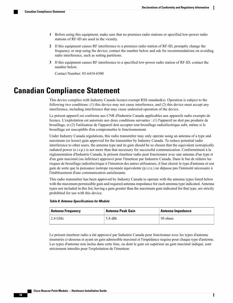
1 Before using this equipment, make sure that no premises radio stations or specified low-power radiostations of RF-ID are used in the vicinity.
2 If this equipment causes RF interference to a premises radio station of RF-ID, promptly change thefrequency or stop using the device; contact the number below and ask for recommendations on avoidingradio interference, such as setting partitions.
3 If this equipment causes RF interference to a specified low-power radio station of RF-ID, contact thenumber below.
Contact Number: 03-6434-6500
Canadian Compliance StatementThis device complies with Industry Canada licence-exempt RSS standard(s). Operation is subject to thefollowing two conditions: (1) this device may not cause interference, and (2) this device must accept anyinterference, including interference that may cause undesired operation of the device.
Le présent appareil est conforme aux CNR d'Industrie Canada applicables aux appareils radio exempts delicence. L'exploitation est autorisée aux deux conditions suivantes : (1) l'appareil ne doit pas produire debrouillage, et (2) l'utilisateur de l'appareil doit accepter tout brouillage radioélectrique subi, même si lebrouillage est susceptible d'en compromettre le fonctionnement.
Under Industry Canada regulations, this radio transmitter may only operate using an antenna of a type andmaximum (or lesser) gain approved for the transmitter by Industry Canada. To reduce potential radiointerference to other users, the antenna type and its gain should be so chosen that the equivalent isotropicallyradiated power (e.i.r.p.) is not more than that necessary for successful communication. Conformément à laréglementation d'Industrie Canada, le présent émetteur radio peut fonctionner avec une antenne d'un type etd'un gain maximal (ou inférieur) approuvé pour l'émetteur par Industrie Canada. Dans le but de réduire lesrisques de brouillage radioélectrique à l'intention des autres utilisateurs, il faut choisir le type d'antenne et songain de sorte que la puissance isotrope rayonnée équivalente (p.i.r.e.) ne dépasse pas l'intensité nécessaire àl'établissement d'une communication satisfaisante.
This radio transmitter has been approved by Industry Canada to operate with the antenna types listed belowwith the maximum permissible gain and required antenna impedance for each antenna type indicated. Antennatypes not included in this list, having a gain greater than the maximum gain indicated for that type, are strictlyprohibited for use with this device.
Table 8: Antenna Specifications for Module
Antenna ImpedanceAntenna Peak GainAntenna Frequency
50 ohms5.8 dBi2.4 GHz
Le présent émetteur radio a été approuvé par Industrie Canada pour fonctionner avec les types d'antenneénumérés ci-dessous et ayant un gain admissible maximal et l'impédance requise pour chaque type d'antenne.Les types d'antenne non inclus dans cette liste, ou dont le gain est supérieur au gain maximal indiqué, sontstrictement interdits pour l'exploitation de l'émetteur.
Cisco Beacon Point Module —Hardware Installation Guide18
Declarations of Conformity and Regulatory InformationCanadian Compliance Statement

Statement 371—Power Cable and Power InjectorWhen installing the product, please use the provided or designated connection cables/power cables/ACadaptors. Using any other cables/adaptors could cause a malfunction or a fire. Electrical Appliance andMaterialSafety Law prohibits the use of UL-certified cables (that have the “UL” shown on the code) for any otherelectrical devices than products designated by CISCO.
The use of cables that are certified by Electrical Appliance and Material Safety Law (that have “PSE” shownon the code) is not limited to CISCO-designated products.
Industry CanadaTable 9: Cisco Beacon Point Models and Certification Numbers
Certification NumberCisco Beacon Models
2461N-825321596AIR-RM-VBLE2-K9=
This Device Meets FCC and International Guidelines forExposure to Radio Waves
Cisco Beacon Point Module includes a radio transmitter and receiver. It is designed not to exceed the limitsfor exposure to radio waves (radio frequency electromagnetic fields) recommended by international guidelines.The guidelines were developed by an independent scientific organization (ICNIRP) and include a substantialsafety margin designed to ensure the safety of all persons, regardless of age and health.
As such the systems are designed to be operated as to avoid contact with the antennas by the end user. It isrecommended to set the system in a location where the antennas can remain at least a minimum distance asspecified from the user in accordance to the regulatory guidelines which are designed to reduce the overallexposure of the user or operator.
Table 10: Separation Distance
LimitDistanceMPE
1.00 mW/cm²30 cm (11.81 inches)0.0005 mW/cm²
The World Health Organization has stated that present scientific information does not indicate the need forany special precautions for the use of wireless devices. They recommend that if you are interested in furtherreducing your exposure then you can easily do so by reorienting antennas away from the user or placing heantennas at a greater separation distance then recommended.
Cisco Beacon Point Module —Hardware Installation Guide 19
Declarations of Conformity and Regulatory InformationStatement 371—Power Cable and Power Injector

This Device Meets the Industry Canada Guidelines for Exposureto Radio Waves
The Cisco Beacon Point Module includes a radio transmitter and receiver. It is designed not to exceed thelimits for exposure to radio waves (radio frequency electromagnetic fields) as referenced in Health CanadaSafety Code 6. The guidelines include a substantial safety margin designed into the limit to ensure the safetyof all persons, regardless of age and health.
As such the systems are designed to be operated as to avoid contact with the antennas by the end user. It isrecommended to set the system in a location where the antennas can remain at least a minimum distance asspecified from the user in accordance to the regulatory guidelines which are designed to reduce the overallexposure of the user or operator.
Table 11: Separation Distance
LimitDistanceMPEFrequency
5.4 W/m²30 cm (11.81 inches)0.005 W/m²2.4 GHz
Health Canada states that present scientific information does not indicate the need for any special precautionsfor the use of wireless devices. They recommend that if you are interested in further reducing your exposureyou can easily do so by reorienting antennas away from the user, placing the antennas at a greater separationdistance than recommended, or lowering the transmitter power output.
Cet appareil est conforme aux directives internationales enmatière d'exposition aux fréquences radioélectriques
Cet appareil de la gamme Cisco Beacon Point Module comprend un émetteur-récepteur radio. Il a été conçude manière à respecter les limites en matière d'exposition aux fréquences radioélectriques (champsélectromagnétiques de fréquence radio), recommandées dans le code de sécurité 6 de Santé Canada. Cesdirectives intègrent une marge de sécurité importante destinée à assurer la sécurité de tous, indépendammentde l'âge et de la santé.
Par conséquent, les systèmes sont conçus pour être exploités en évitant que l'utilisateur n'entre en contact avecles antennes. Il est recommandé de poser le système là où les antennes sont à une distance minimale telle queprécisée par l'utilisateur conformément aux directives réglementaires qui sont conçues pour réduire l'expositiongénérale de l'utilisateur ou de l'opérateur.
Table 12: Distance d'éloignement
LimiteDistanceMPEFréquence
5.4 W/m²30 cm (11.81 inches)0.005 W/m²2.4 GHz
Cisco Beacon Point Module —Hardware Installation Guide20
Declarations of Conformity and Regulatory InformationThis Device Meets the Industry Canada Guidelines for Exposure to Radio Waves
Santé Canada affirme que la littérature scientifique actuelle n'indique pas qu'il faille prendre des précautionsparticulières lors de l'utilisation d'un appareil sans fil. Si vous voulez réduire votre exposition encore davantage,selon l'agence, vous pouvez facilement le faire en réorientant les antennes afin qu'elles soient dirigées à l'écartde l'utilisateur, en les plaçant à une distance d'éloignement supérieure à celle recommandée ou en réduisantla puissance de sortie de l'émetteur.
Additional Information on RF ExposureYou can find additional information on the subject at the following links:
• Cisco Systems Spread Spectrum Radios and RF Safety white paper at this location.
• FCC Bulletin 56: Questions and Answers about Biological Effects and Potential Hazards of RadioFrequency Electromagnetic Fields.
• FCC Bulletin 65: Evaluating Compliance with the FCC guidelines for Human Exposure to RadioFrequency Electromagnetic Fields.
• You can obtain additional information from the following organizations.
•World Health Organization Internal Commission on Non-Ionizing Radiation Protection at this location.
• United Kingdom, National Radiological Protection Board at this location.
• Cellular Telecommunications Association at this location.
• The Mobile Manufacturers Forum at this location.
Declaration of Conformity StatementsAll the Declaration of Conformity statements related to this product can be found at this location
Cisco Beacon Point Module —Hardware Installation Guide 21
Declarations of Conformity and Regulatory InformationAdditional Information on RF Exposure

Cisco Beacon Point Module —Hardware Installation Guide22
Declarations of Conformity and Regulatory InformationDeclaration of Conformity Statements