cisco 12000 (5060) - ca technologies - ca support...
TRANSCRIPT

Cisco 12000
Device Management
Supports Management Module SM-CIS1014
Titlep
age

D e v i c e M a n a g e m e n t Page 2 C i s c o 1 2 0 0 0
Copyright NoticeDocument 5060. Copyright © 2002 - present by Aprisma Management Technologies, Inc. All rights reserved worldwide. Use, duplication, or disclosure by the United States government is subject to the restrictions set forth in DFARS 252.227-7013(c)(1)(ii) and FAR 52.227-19.Liability DisclaimerAprisma Management Technologies, Inc. (“Aprisma”) reserves the right to make changes in specifications and other information contained in this document without prior notice. In all cases, the reader should contact Aprisma to inquire if any changes have been made.
The hardware, firmware, or software described in this manual is subject to change without notice.
IN NO EVENT SHALL APRISMA, ITS EMPLOYEES, OFFICERS, DIRECTORS, AGENTS, OR AFFILIATES BE LIABLE FOR ANY INCIDENTAL, INDIRECT, SPECIAL, OR CONSEQUENTIAL DAMAGES WHATSOEVER (INCLUDING BUT NOT LIMITED TO LOST PROFITS) ARISING OUT OF OR RELATED TO THIS MANUAL OR THE INFORMATION CONTAINED IN IT, EVEN IF APRISMA HAS BEEN ADVISED OF, HAS KNOWN, OR SHOULD HAVE KNOWN, THE POSSIBILITY OF SUCH DAMAGES.
Trademark, Service Mark, and Logo InformationSPECTRUM, IMT, and the SPECTRUM IMT/VNM logo are registered trademarks of Aprisma Management Technologies, Inc., or its affiliates. APRISMA, APRISMA MANAGEMENT TECHNOLOGIES, the APRISMA MANAGEMENT TECHNOLOGIES logo, MANAGE WHAT MATTERS, DCM, VNM, SpectroGRAPH, SpectroSERVER, Inductive Modeling Technology, Device Communications Manager, SPECTRUM Security Manager, and Virtual Network Machine are unregistered trademarks of Aprisma Management Technologies, Inc., or its affiliates. For a complete list of Aprisma trademarks, service marks, and trade names, go tohttp://www.aprisma.com/manuals/trademark-list.htm.
All referenced trademarks, service marks, and trade names identified in this document, whether registered or unregistered, are the intellectual property of their respective owners. No rights are granted by Aprisma Management Technologies, Inc., to use such marks, whether by implication, estoppel, or otherwise. If you have comments or concerns
about trademark or copyright references, please send an e-mail to [email protected]; we will do our best to help.
Restricted Rights Notice(Applicable to licenses to the United States government only.)This software and/or user documentation is/are provided with RESTRICTED AND LIMITED RIGHTS. Use, duplication, or disclosure by the government is subject to restrictions as set forth in FAR 52.227-14 (June 1987) Alternate III(g)(3) (June 1987), FAR 52.227-19 (June 1987), or DFARS 52.227-7013(c)(1)(ii) (June 1988), and/or in similar or successor clauses in the FAR or DFARS, or in the DOD or NASA FAR Supplement, as applicable. Contractor/manufacturer is Aprisma Management Technologies, Inc. In the event the government seeks to obtain the software pursuant to standard commercial practice, this software agreement, instead of the noted regulatory clauses, shall control the terms of the government's license.Virus DisclaimerAprisma makes no representations or warranties to the effect that the licensed software is virus-free.
Aprisma has tested its software with current virus-checking technologies. However, because no antivirus system is 100 percent effective, we strongly recommend that you write-protect the licensed software and verify (with an antivirus system in which you have confidence) that the licensed software, prior to installation, is virus-free.
Contact InformationAprisma Management Technologies, Inc.273 Corporate DrivePortsmouth, NH 03801Phone: 603-334-2100U.S. toll-free: 877-468-1448Web site: http://www.aprisma.com

D e v i c e M a n a g e m e n t Page 3 C i s c o 1 2 0 0 0
ContentsINTRODUCTION 5
Purpose and Scope ........................................................5Required Reading ...........................................................5Supported Devices..........................................................6The SPECTRUM Model ..................................................6
EVENTS 8
CISCOVIEW 9
DEVICE VIEW 11
Interface Icons ...........................................................12Sub-Interfaces Button ............................................13Interface Icon Subviews Menu...............................14
Secondary Address Panel View ................................15
DEVICE TOPOLOGY VIEW 16
Interface Device Topology View ...................................16Sub-Interfaces Topology View ......................................17
APPLICATION VIEWS 18
Main Application View...................................................18Supported Applications .................................................19
Common Applications................................................19Device-Specific MIBs.................................................20
Cisco Chassis Application............................................. 22Cisco Chassis Card View .......................................... 22Cisco Card Interface View......................................... 22Cisco Chassis General Information View .................. 23
ROM Information ................................................ 23RAM Information ................................................ 24
Cisco Voice Application ................................................ 24Cisco Flash Application................................................. 24
Cisco Flash Configuration View ................................ 25Flash Directory Table............................................. 25
Flash Device Chip Properties Table View ................. 25Flash Copy Operations Table View...........................26Flash Device Properties Table View ......................... 26Flash File Properties Table View............................... 27Flash Miscellaneous Operations Table View ............ 27Flash Device Partition Properties Table View ........... 28Flash Partitioning Operations Table View ................. 28
Cisco Ping Application .................................................. 29Ping Request Entry View........................................... 29
Ping Request Entries ............................................. 29Saved Ping Requests ............................................ 31
Cisco Queue Application............................................... 31Queue Interface View................................................ 32Queue Statistics View ............................................... 32Queue Rotation Interface View ................................. 32
EnvMon Application ...................................................... 33Enable Notifications................................................... 33
C o n t e n t s C o n t e n t s
D e v i c e M a n a g e m e n t Page 4 C i s c o 1 2 0 0 0
Fan Status .................................................................33Power Supply Status .................................................34Temperature Status...................................................34Voltage Status ...........................................................34
Discovery Application....................................................35Discovery Cache Table View.....................................35Interface Discovery Status Table...............................36
Cisco Terminal Server Application ................................37Line Configuration View.............................................37Cisco Terminal Server Line View ..............................37Cisco Terminal Server Session View ........................39
Cisco Memory Pool Application ....................................39Cisco Memory Pool Monitor Table View....................40
PERFORMANCE VIEWS 41
Device Performance View.............................................42Port Performance View .................................................42
CONFIGURATION VIEWS 43
Cisco Configuration View..............................................43Interface Configuration Table ....................................44
Redundancy/Model Reconfiguration Options View45Interface Address Translation Table View .............47Network/Host Configuration View ..........................47
Network Configuration........................................47Host Configuration..............................................47
Cisco Running Config Event/Alarm Configuration View ................................................................49
Interface Configuration View.........................................50
SYSLOG TRAP SUPPORT 51
MODEL INFORMATION VIEW 52
INDEX 56
D e v i c e M a n a g e m e n t Page 5 C i s c o 1 2 0 0 0
Introduction
This section introduces the SPECTRUM Device Management documentation for Cisco 12000.
This introduction contains the following topics:
• Purpose and Scope
• Required Reading
• Supported Devices (Page 6)
• The SPECTRUM Model (Page 6)
Purpose and ScopeUse this document as a guide for managing the Cisco 12000 devices described on Page 6 with SPECTRUM management module SM-CIS1014. This document describes the icons, menus, and views that enable you to remotely monitor, configure, and troubleshoot Cisco 12000 devices through software models in your SPECTRUM database.
Information specific to SM-CIS1014 is what is primarily included in this document. For general information about device management using SPECTRUM and explanations of SPECTRUM
functionality and navigation techniques, refer to the topics listed under Required Reading.
Required ReadingTo use this documentation effectively, you must be familiar with the information covered by the other SPECTRUM online documents listed below.
• Getting Started with SPECTRUM for Operators
• Getting Started with SPECTRUM for Administrators
• How to Manage Your Network with SPECTRUM
• SPECTRUM Views
• SPECTRUM Menus
• SPECTRUM Icons
• SPECTRUM Software Release Notice

I n t r o d u c t i o n S u p p o r t e d D e v i c e s
D e v i c e M a n a g e m e n t Page 6 C i s c o 1 2 0 0 0
Supported DevicesSPECTRUM management module SM-CIS1014 currently lets you model Cisco 12000 devices. The Cisco 12000 series gigabit switch router (GSR) is the premier routing product family from Cisco designed and developed for the core of service provider and enterprise IP backbones.
• Cisco 12012 GSR- has 12 slots that can be used to support up to 132 DS3, 44 OC-3c/STM-1c, 44 OC-12c/STM-4c, or 11 OC-48c/STM-16c interfaces.
• Cisco 12008 - has eight slots that can be used to support up to 84 DS3, 28 OC-3c/STM-1c, and 28 OC-12c/STM-4c or 7 OC-48c/STM-16c interfaces.
The SPECTRUM ModelThe model types for the Cisco 12000 devices are Cisco_12012 and Cisco_12008.
Modeling results in the creation of Device icons that represent the devices and Application icons that represent their supported applications.
The Device icons contain double-click zones and provide access to Icon Subviews menus that let you perform device management activities.
As Figure 1 shows, the appearance of the Device icons varies slightly depending on the kind of view it appears in.
Figure 1: Device Icons
Model Name
Cisco_12012
Model Name
Cisco_12012
Small Device icon appears inTopology, Device Topology, Application Views
Large Device iconappears in Device Topology,Location, and Interface Device views.
I n t r o d u c t i o n T h e S P E C T R U M M o d e l
D e v i c e M a n a g e m e n t Page 7 C i s c o 1 2 0 0 0
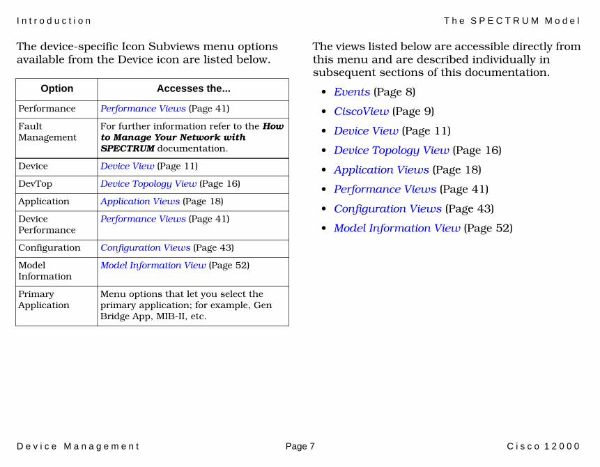
The device-specific Icon Subviews menu options available from the Device icon are listed below.
The views listed below are accessible directly from this menu and are described individually in subsequent sections of this documentation.
• Events (Page 8)
• CiscoView (Page 9)
• Device View (Page 11)
• Device Topology View (Page 16)
• Application Views (Page 18)
• Performance Views (Page 41)
• Configuration Views (Page 43)
• Model Information View (Page 52)
Option Accesses the...
Performance Performance Views (Page 41)
Fault Management
For further information refer to the How to Manage Your Network with SPECTRUM documentation.
Device Device View (Page 11)
DevTop Device Topology View (Page 16)
Application Application Views (Page 18)
Device Performance
Performance Views (Page 41)
Configuration Configuration Views (Page 43)
Model Information
Model Information View (Page 52)
Primary Application
Menu options that let you select the primary application; for example, Gen Bridge App, MIB-II, etc.

D e v i c e M a n a g e m e n t Page 8 C i s c o 1 2 0 0 0
Events
This section provides the range of event messages that are specific to the Cisco 12000.
The Cisco Router has several event and alarm messages that are specific to its devices. If these messages are not sufficient and you wish to create your own messages, or view the existing messages for the Router, you can do so using the ECEditor.
The event messages for the Router, which range from Event03250000 to Event03250002, can be found in the following directory:
<install area>/SG-Support/CsEvFormat

D e v i c e M a n a g e m e n t Page 9 C i s c o 1 2 0 0 0
CiscoView
This section describes how to access Cisco’s CiscoView management software from SPECTRUM.
CiscoView is management software specific to Cisco Routers.
The Cisco_12000 model type provides a menu option from the Device icon that is used to launch CiscoView.
For SolarisAdd the following information to the /opt/SPECTRUM/spectrum60.env file:
#CiscoView 3.0
CVIEW =<path_to_ciscoview>
For Windows NT and Windows 2000From the Start>Run window, type
regedit (registry editor)
Navigate to HKEY_LOCAL_MACHINE>SOFTWARE> Aprisma Management Technologies> Spectrum60> Environment
Choose Edit>New>String Value
Type CVIEW for the name, and <path_to_ciscoview> as the string value.
Zoom - >CiscoViewDeviceDevTop
Application
Device PerformanceAcknowledge
Cisco_12012

C i s c o V i e w
D e v i c e M a n a g e m e n t Page 10 C i s c o 1 2 0 0 0
Note:Note:
CiscoView 3.0 will appear as “Cisco View” on your device menu after the above steps have been followed. This should not be confused with “CiscoView”, which denotes the CiscoWorks 2000 CiscoView. The CiscoWorks 2000 menu picks will only appear in the device menu if the SPECTRUM Adapter script has been run. See the CiscoWorks 2000 documentation for further information.

D e v i c e M a n a g e m e n t Page 11 C i s c o 1 2 0 0 0
Device View
This section describes the Device view and subviews available for models of Cisco 12000 devices in SPECTRUM.
Access: From the Icon Subviews menu for the Device icon, select Device.
This view (Figure 2) uses icons and labels to represent the device and its components, such as modules, ports, and applications. The view provides dynamic configuration and performance information for each of the device’s serial and network I/O ports, which are represented by Interface icons in the bottom panel of the view. The middle panel of the view displays a Device icon, which lets you monitor the device operation and access other device-specific views.
Figure 2: Device View
SpectroGRAPH: Router Device: Model Name
File View HelpTools
Model NameContactDescriptionLocation
Sys Up TimeManufacturerDevice TypeSerial Number
Network Address
Interface Description
Filter Physical
Interface Options PanelDevice Icon
Cisco 12000
Model Name
1Ethernet
0:0:1D:F:FD:B6
ei0
0.0.0.0
ON
5SFTWARLPBK
0:0:1D:F:FD:B6
lo0
0.0.0.0
ON
9ATM8023
0:0:1D:F:FD:B6
zn1
0.0.0.0
ON
512AAL5
UAAL5
0.0.0.0
ON
2ATMCPU
0.0.0.0
ON
6ATM portCPU.1
0.0.0.0
ON
ATM7A1
0.0.0.0
ON
ATM7B1
0.0.0.0
ON
ATM7B2
0.0.0.0
ON
ATM7B3
0.0.0.0
ON
ATM8B1
0.0.0.0
ON
ATM8B2
0.0.0.0
ON
ATM8B3
0.0.0.0
ON
ATM8B4
0.0.0.0
ON
10
2783905 2783909
11
7
3 4
8
Interface Icons
Bookmarks
Model Name of type Cisco 1200 of Landscape node: Primary
Primary Application Gen Bridge App
D e v i c e V i e w
D e v i c e M a n a g e m e n t Page 12 C i s c o 1 2 0 0 0
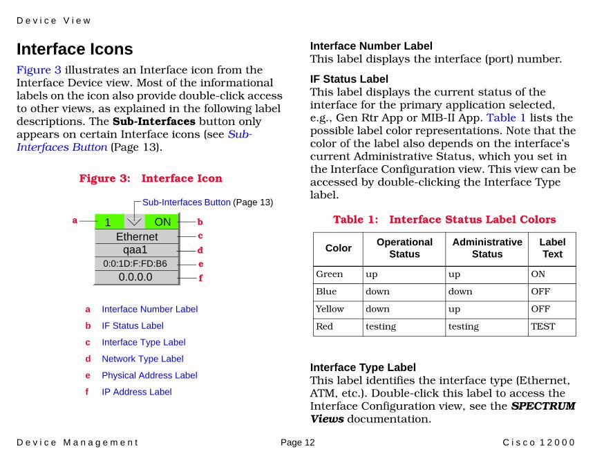
Interface IconsFigure 3 illustrates an Interface icon from the Interface Device view. Most of the informational labels on the icon also provide double-click access to other views, as explained in the following label descriptions. The Sub-Interfaces button only appears on certain Interface icons (see Sub-Interfaces Button (Page 13).
Figure 3: Interface Icon
Interface Number LabelThis label displays the interface (port) number.
IF Status LabelThis label displays the current status of the interface for the primary application selected, e.g., Gen Rtr App or MIB-II App. Table 1 lists the possible label color representations. Note that the color of the label also depends on the interface’s current Administrative Status, which you set in the Interface Configuration view. This view can be accessed by double-clicking the Interface Type label.
Interface Type LabelThis label identifies the interface type (Ethernet, ATM, etc.). Double-click this label to access the Interface Configuration view, see the SPECTRUM Views documentation.
c
f
b1Ethernet
0:0:1D:F:FD:B6
a
a Interface Number Label
b IF Status Label
c Interface Type Label
d Network Type Label
e Physical Address Label
f IP Address Label
qaa1
0.0.0.0
d
e
ON
Sub-Interfaces Button (Page 13)
Table 1: Interface Status Label Colors
ColorOperational
StatusAdministrative
StatusLabelText
Green up up ON
Blue down down OFF
Yellow down up OFF
Red testing testing TEST
D e v i c e V i e w
D e v i c e M a n a g e m e n t Page 13 C i s c o 1 2 0 0 0
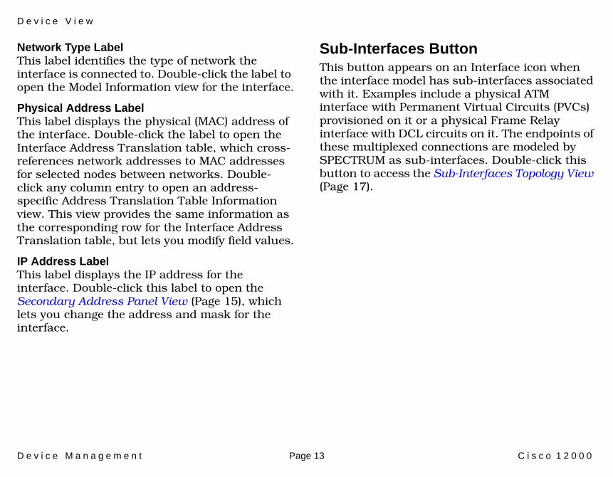
Network Type LabelThis label identifies the type of network the interface is connected to. Double-click the label to open the Model Information view for the interface.
Physical Address LabelThis label displays the physical (MAC) address of the interface. Double-click the label to open the Interface Address Translation table, which cross-references network addresses to MAC addresses for selected nodes between networks. Double-click any column entry to open an address-specific Address Translation Table Information view. This view provides the same information as the corresponding row for the Interface Address Translation table, but lets you modify field values.
IP Address LabelThis label displays the IP address for the interface. Double-click this label to open the Secondary Address Panel View (Page 15), which lets you change the address and mask for the interface.
Sub-Interfaces ButtonThis button appears on an Interface icon when the interface model has sub-interfaces associated with it. Examples include a physical ATM interface with Permanent Virtual Circuits (PVCs) provisioned on it or a physical Frame Relay interface with DCL circuits on it. The endpoints of these multiplexed connections are modeled by SPECTRUM as sub-interfaces. Double-click this button to access the Sub-Interfaces Topology View (Page 17).

D e v i c e V i e w
D e v i c e M a n a g e m e n t Page 14 C i s c o 1 2 0 0 0
Interface Icon Subviews Menu Table 2 lists the Icon Subviews menu options available for the Interface icon.
Table 2: Interface Menu Options
Option Accesses the...
Detail Interface Detail view, which displays Packet, Error, and Discard Breakdown pie charts.
Sub-Interfaces Sub-Interfaces Topology View (Page 17)
IF Configuration Interface Configuration view (see SPECTRUM Views).
Address Translation Table
Address Translation Table (AT) (see SPECTRUM Views).
Secondary Address Panel
Secondary Address Panel View (Page 15).
Thresholds Interface Threshold view, which lets you set the on/off alarm thresholds for load, packet rate, error rate, and % discarded for the interface.
Model Information Model Information View (Page 52).
Trap Configuration Interface Trap Configuration view (see How to Manage Your Network with SPECTRUM).
Cisco Network Info Cisco Interface Network View which displays In Packets, Out Packets, In Octets, and Out Octets pie charts.
Cisco Router Info Cisco Interface Router View which displays generic routing applications information.
Cisco Traffic Info Cisco Interface Traffic View which displays slow and fast traffic pie charts.
Cisco Other Info Other Cisco Interface View which displays In Packets, Out Packets, In Octets, and Out Octets pie charts.
Table 2: Interface Menu Options (Continued)
Option Accesses the...

D e v i c e V i e w
D e v i c e M a n a g e m e n t Page 15 C i s c o 1 2 0 0 0
Secondary Address Panel ViewAccess: From the Icon Subviews menu for the Interface icon in the Interface Device view, select Secondary Address Panel.
This panel provides a table of IP addresses and masks obtained from the Address Translation table within the device’s firmware. You can change the current address displayed in the IP Address field by selecting an entry from the table in this panel and clicking the Update button.

D e v i c e M a n a g e m e n t Page 16 C i s c o 1 2 0 0 0
Device Topology View
This section describes the Device Topology views available for models of Cisco 12000 devices in SPECTRUM.
Device Topology views show the connections between a modeled device and other network entities. There are two types of Device Topology views available for models of Cisco 12000 devices:
• Interface Device Topology View• Sub-Interfaces Topology View (Page 17)
Interface Device Topology ViewAccess: From the Icon Subviews menu for the Device icon, select DevTop.
The lower panel (Figure 4) uses Interface icons to represent the device’s serial/network/I/O ports. These icons provide the same information and menu options as those in the Device View (Page 11). If a device is connected to an interface, a Device icon appears on the vertical bar above the Interface icon along with an icon representing the network group that contains the device. See SPECTRUM Views for more details.
Figure 4: Device Topology View
File View HelpTools
1Ethernet
0:0:1D:F:FD:B6ei0
0.0.0.0
ON 2ATM
0:0:1D:F:FD:B6A2
0.0.0.0
ON 3ATM
0:0:1D:F:FD:B6CPU
0.0.0.0
ON
Cisco 12000
Model Name
Bookmarks
SpectroGRAPH: Device Topology: Model Name
Graphic ofCisco 12000
Device
Model Name of type Model Type of Landscape node: Primary

D e v i c e T o p o l o g y V i e w S u b - I n t e r f a c e s T o p o l o g y V i e w
D e v i c e M a n a g e m e n t Page 17 C i s c o 1 2 0 0 0
Sub-Interfaces Topology ViewAccess: From the Icon Subviews menu for an Interface icon whose interface contains sub-interfaces, select Sub-Interfaces.
When present, the endpoints associated with multiplexed, physical connections are modeled by SPECTRUM as sub-interfaces. This includes, for example, Permanent Virtual Circuits (PVCs) on a physical ATM interface and DCL circuits on a physical Frame Relay interface.
The lower panel of the Sub-Interfaces Topology view (Figure 5) uses Interface icons to represent these non-physical entities and circuits that are connected to the physical interface. These Interface icons provide the same labels and menu options as the Interface icons in the Device View (Page 11).
Figure 5: Sub-Interfaces Topology View
File View Tools Bookmarks Help
ethernet
FastEthernet0/1
2 ON
132.127.118.23
SpectroGRAPH: Device Topology: Model Name
propVirtual
FastEthernet0/1.1
1 ON
132.127.118.24
0.0.FO:27.62.ID
0.0.FO:27.62.ID

D e v i c e M a n a g e m e n t Page 18 C i s c o 1 2 0 0 0
Application Views
This section describes the main Application view and the associated application-specific subviews available for models of Cisco 12000 devices in SPECTRUM.
Access: From the Icon Subviews menu for the Device icon, select Application.
Main Application ViewWhen a device model is created, SPECTRUM automatically creates models for each of the major and minor applications supported by the device. The main Application view identifies all of these application models, shows their current condition status, and provides access to application-specific subviews. Figure 6 shows this view in the Icon mode. If you prefer the List mode, which displays applications as text labels, select View > Mode > List.
For more information on this view, refer to the MIBs and the Application View documentation.
Figure 6: Main Application View
SpectroGRAPH: Application: Model Name
Model Name
Contact
Description
Location
Network Address System Up Time
Manufacturer
Device Type
Serial Number
Model Name
6E132_25
Model Name
File View Tools Bookmarks
Model Name of type Cisco 12000 of Landscape node: Primary
Help

A p p l i c a t i o n V i e w s S u p p o r t e d A p p l i c a t i o n s
D e v i c e M a n a g e m e n t Page 19 C i s c o 1 2 0 0 0
Supported ApplicationsSPECTRUM’s applications can be grouped within two general categories as follows:
• Applications associated with non proprietary MIBs. See Common Applications below.
• Applications associated with device-specific MIBs. See Device-Specific MIBs (Page 20).
Common ApplicationsFor the most part, these applications represent the non proprietary MIBs supported by devices. Listed below (beneath the title of the SPECTRUM document that describes them) are some of the common applications currently supported by SPECTRUM. Refer to these documents when your devices support these applications.
• Routing Applications- Generic Routing- Repeater- AppleTalk- DECnet
- OSPF- OSPF2- BGP4- VRRP- RFC 2932
• Bridging Applications- Ethernet Special Database- Spanning Tree- Static- Transparent- PPP Bridging- Source Routing- Translation- QBridge
• MIB II Applications- SNMP- IP- ICMP- TCP- System2- UDP
• Transmission Applications- FDDI- Point to Point- DS1- DS3
Note:Note:
The documents listed below (in bold font) are available for viewing at:
www.aprisma.com/manuals/

A p p l i c a t i o n V i e w s S u p p o r t e d A p p l i c a t i o n s
D e v i c e M a n a g e m e n t Page 20 C i s c o 1 2 0 0 0
- RS-232- WAN- Frame Relay- Token Ring- Ethernet- Fast Ethernet- RFC 1317App- RFC 1285App- RFC 1315App- 802.11App- SONET
• Technology Applications- APPN- ATM Client- DHCP- DLSw- PNNI- RFC 1316App- RFC 1514- RFC 2287- RFC 2790- RFC 2925
• DOCSIS Applications- DOCSISCblDvApp - DOCSISQOSApp- DOCSISBPI2App - DOCSISBPIApp
- DOCSISIFApp
• Digital Subscriber Line (DSL) Applications- ADSL
Device-Specific MIBsSPECTRUM imports the following device-level proprietary MIBs into its database:
• CISCO-BSC-MIB • CISCO-BSTUN-MIB • CISCO-CIPCSNA-MIB • CISCO-CHANNEL-MIB • CISCO-PING-MIB • CISCO-ENVMON-MIB • CISCO-INTERFACES-MIB • CISCO-IP-MIB • CISCO-NOVELL-MIB • CISCO-TS-MIB • CISCO-VINES-MIB • CISCO-XNS-MIB • CISCO-CHASSIS-MIB • CISCO-ENV-MIB • CISCO-DSPU-MIB • CISCO-DLSW-MIB • CISCO-ISDN-MIB • CISCO-QUEUE-MIB

A p p l i c a t i o n V i e w s S u p p o r t e d A p p l i c a t i o n s
D e v i c e M a n a g e m e n t Page 21 C i s c o 1 2 0 0 0
• CISCO-REPEATER-MIB • CISCO-RSRB-MIB • CISCO-SDLLC-MIB • CISCO-SNAPSHOT-MIB • CISCO-STUN-MIB • CISCO-DECNET-MIB • CISCO-CALL_HISTORY_MIB • CISCO-IPMROUTE-MIB• CISCO-PIM-MIB• CISCO-HSRP-MIB • CISCO-HSRP-EXT-MIB
These MIBs can be used in conjunction with SPECTRUM’s optional customization products (referred to as the Level I Tool Kits) to create application models and views that display the condition of selected MIB objects.
The following device-specific applications are described in the remainder of this section:
• Cisco Chassis Application (Page 22)• Cisco Voice Application (Page 24)• Cisco Flash Application (Page 24)• Cisco Ping Application (Page 29)• Cisco Queue Application (Page 31)• EnvMon Application (Page 33)• Discovery Application (Page 35)• Cisco Terminal Server Application (Page 37)• Cisco Memory Pool Monitor Table View
(Page 40)The Cisco application model types common to multiple Cisco device model types are described in the Cisco Applications (5127) guide.
Note:Note:
Aprisma Management Technologies can provide training, technical assistance, and custom engineering support services for creating application models and their associated views.
A p p l i c a t i o n V i e w s C i s c o C h a s s i s A p p l i c a t i o n
D e v i c e M a n a g e m e n t Page 22 C i s c o 1 2 0 0 0
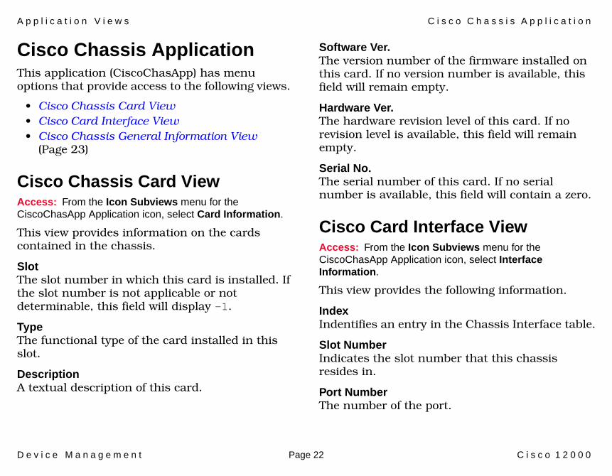
Cisco Chassis Application This application (CiscoChasApp) has menu options that provide access to the following views.
• Cisco Chassis Card View• Cisco Card Interface View• Cisco Chassis General Information View
(Page 23)
Cisco Chassis Card ViewAccess: From the Icon Subviews menu for the CiscoChasApp Application icon, select Card Information.
This view provides information on the cards contained in the chassis.
SlotThe slot number in which this card is installed. If the slot number is not applicable or not determinable, this field will display -1.
TypeThe functional type of the card installed in this slot.
DescriptionA textual description of this card.
Software Ver.The version number of the firmware installed on this card. If no version number is available, this field will remain empty.
Hardware Ver.The hardware revision level of this card. If no revision level is available, this field will remain empty.
Serial No.The serial number of this card. If no serial number is available, this field will contain a zero.
Cisco Card Interface ViewAccess: From the Icon Subviews menu for the CiscoChasApp Application icon, select Interface Information.
This view provides the following information.
IndexIndentifies an entry in the Chassis Interface table.
Slot NumberIndicates the slot number that this chassis resides in.
Port NumberThe number of the port.

A p p l i c a t i o n V i e w s C i s c o C h a s s i s A p p l i c a t i o n
D e v i c e M a n a g e m e n t Page 23 C i s c o 1 2 0 0 0
Card IndexIdentifies the number of the card.
Enabled Connector TypeEnable or disable the connector.
Cisco Chassis General Information ViewAccess: From the Icon Subviews menu for the CiscoChasApp Application icon, select General.
This view displays information on the chassis in which the router is installed. This view is divided into the three sections described below.
Chassis InformationThis section of the Chassis General Information view provides the following physical information about the chassis.
Hardware Revision LevelThe version number of the chassis hardware. If the version number is not available, this field will remain empty.
Chassis TypeThe type of chassis. Possible chassis types are: Unknown, Multibus, Agsplus, Igs, c2000, c3000, c4000, c7000, cs-500, c7010, c2500, and c4500.
Chassis ID/Serial No.A unique identifier for this chassis. The default value is the serial number of the chassis. If no serial number is available and no alternative ID has been set for the chassis, this field will remain empty.
Number of Chassis SlotsThe number of slots in this chassis model.
ROM InformationThis section of the Chassis General Information view provides the following information about the ROM installed in the chassis.
ROM Monitor VersionThe version number of the ROM monitor.
ROM Software VersionThe version number of the ROM system software. If no version number is available, this field will remain empty.
Config RegisterThe current value of the configuration register.
A p p l i c a t i o n V i e w s C i s c o V o i c e A p p l i c a t i o n
D e v i c e M a n a g e m e n t Page 24 C i s c o 1 2 0 0 0
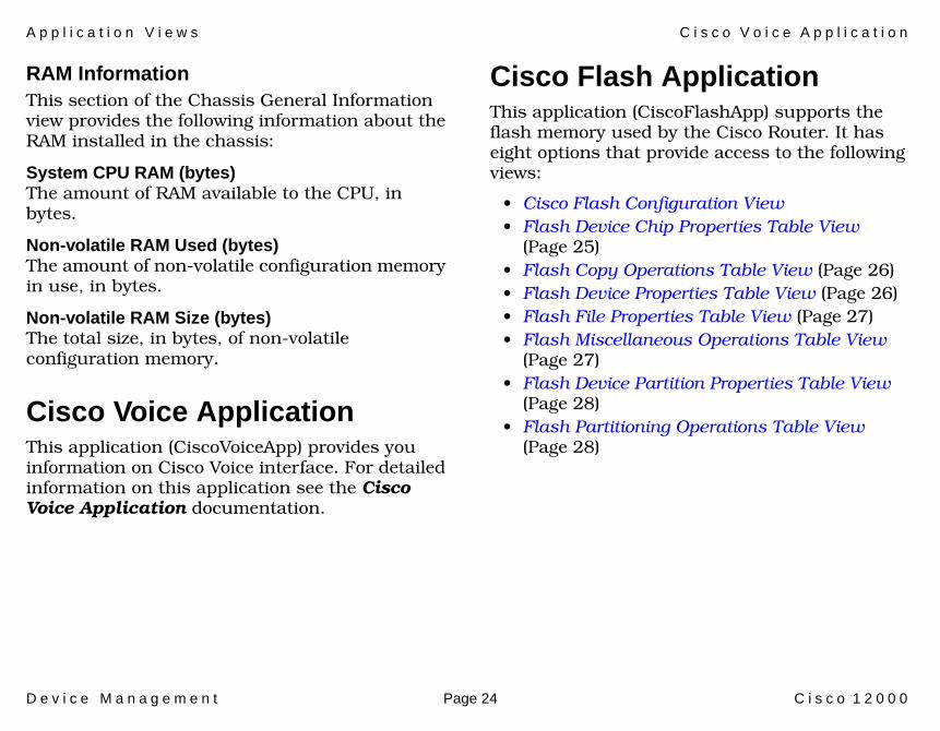
RAM InformationThis section of the Chassis General Information view provides the following information about the RAM installed in the chassis:
System CPU RAM (bytes)The amount of RAM available to the CPU, in bytes.
Non-volatile RAM Used (bytes)The amount of non-volatile configuration memory in use, in bytes.
Non-volatile RAM Size (bytes)The total size, in bytes, of non-volatile configuration memory.
Cisco Voice ApplicationThis application (CiscoVoiceApp) provides you information on Cisco Voice interface. For detailed information on this application see the Cisco Voice Application documentation.
Cisco Flash Application This application (CiscoFlashApp) supports the flash memory used by the Cisco Router. It has eight options that provide access to the following views:
• Cisco Flash Configuration View• Flash Device Chip Properties Table View
(Page 25)• Flash Copy Operations Table View (Page 26)• Flash Device Properties Table View (Page 26)• Flash File Properties Table View (Page 27)• Flash Miscellaneous Operations Table View
(Page 27)• Flash Device Partition Properties Table View
(Page 28)• Flash Partitioning Operations Table View
(Page 28)

A p p l i c a t i o n V i e w s C i s c o F l a s h A p p l i c a t i o n
D e v i c e M a n a g e m e n t Page 25 C i s c o 1 2 0 0 0
Cisco Flash Configuration View Access: From the Icon Subviews menu for the CiscoFlashApp Application icon, select Flash Configuration.
This view provides the following information.
Flash Size (Bytes)Total size, in bytes, of flash memory.
Available (Bytes)Unused size, in bytes, of flash memory.
Flash writeThe current write permission is Disabled or Enabled.
Flash Directory TableThis table within the Flash Configuration view, provides the following information.
Name The flash device name.
SizeThe total size of the flash device.
StatusThe status of the flash device.
There are also seven buttons that access the additional Flash views or you can access these
views from the Icon Subviews menu for the CiscoFlashApp Application. The buttons are: Copy Operations, Misc Operations, Device Properties, Chip Properties, Partition Properties, Partitioning Operations, and File Properties.
Flash Device Chip Properties Table ViewAccess: From the Icon Subviews menu for the CiscoFlashApp Application icon, select Chip Properties.
This view displays the following flash device chip information for each initialized flash device.
DescriptionThe flash chip name corresponding to the chip code.
Write RetriesA cumulative count of write retries done on this chip.
Erase RetriesA cumulative count of erase retries done on this chip.
A p p l i c a t i o n V i e w s C i s c o F l a s h A p p l i c a t i o n
D e v i c e M a n a g e m e n t Page 26 C i s c o 1 2 0 0 0
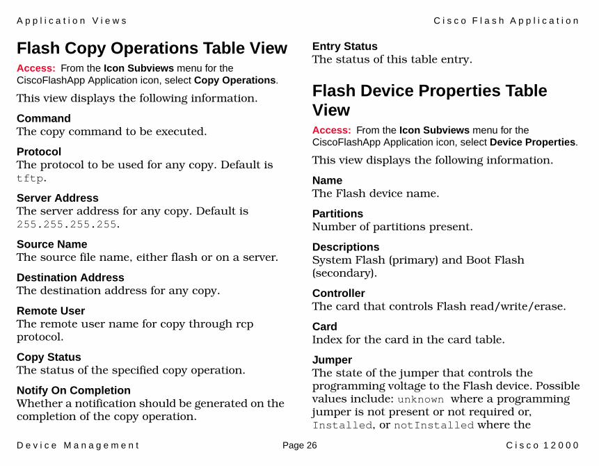
Flash Copy Operations Table ViewAccess: From the Icon Subviews menu for the CiscoFlashApp Application icon, select Copy Operations.
This view displays the following information.
CommandThe copy command to be executed.
ProtocolThe protocol to be used for any copy. Default is tftp.
Server AddressThe server address for any copy. Default is 255.255.255.255.
Source NameThe source file name, either flash or on a server.
Destination AddressThe destination address for any copy.
Remote UserThe remote user name for copy through rcp protocol.
Copy StatusThe status of the specified copy operation.
Notify On CompletionWhether a notification should be generated on the completion of the copy operation.
Entry StatusThe status of this table entry.
Flash Device Properties Table ViewAccess: From the Icon Subviews menu for the CiscoFlashApp Application icon, select Device Properties.
This view displays the following information.
Name The Flash device name.
PartitionsNumber of partitions present.
DescriptionsSystem Flash (primary) and Boot Flash (secondary).
ControllerThe card that controls Flash read/write/erase.
Card Index for the card in the card table.
JumperThe state of the jumper that controls the programming voltage to the Flash device. Possible values include: unknown where a programming jumper is not present or not required or, Installed, or notInstalled where the

A p p l i c a t i o n V i e w s C i s c o F l a s h A p p l i c a t i o n
D e v i c e M a n a g e m e n t Page 27 C i s c o 1 2 0 0 0
programming jumper state can be read back via a hardware register.
Init TimeThe time (system time) the device was initialized.
Flash File Properties Table ViewAccess: From the Icon Subviews menu for the CiscoFlashApp Application icon, select File Properties.
This view displays the following information for the files in a flash partition.
Name The name for the file specified by the user copying in the file.
SizeThe size of the file in bytes.
StatusThe status of the file.
Flash Miscellaneous Operations Table ViewAccess: From the Icon Subviews menu for the CiscoFlashApp Application icon, select Miscellaneous Operations.
This view displays the following information.
CommandThe command to be executed.
DestinationThe destination file.
StatusThe status of the specified operation.
Notify On CompletionWhether a notification should be generated on the completion of the copy operation.
Entry StatusThe status of this table entry.
TimeThe time taken for the operation.

A p p l i c a t i o n V i e w s C i s c o F l a s h A p p l i c a t i o n
D e v i c e M a n a g e m e n t Page 28 C i s c o 1 2 0 0 0
Flash Device Partition Properties Table ViewAccess: From the Icon Subviews menu for the CiscoFlashApp Application icon, select Partition Properties.
This view displays the following information.
Name The name for this partition used by the system.
Start ChipThe chip sequence number for the first chip in the partition.
End ChipThe chip sequence number for the last chip in the partition.
SizeThe flash partition size.
File CountThe number of files in the partition.
Checksum AlgorithmThe identifier for the checksum method used by the file system. When a file system writes a file to flash, it checksums the data written.
Flash Partitioning Operations Table ViewAccess: From the Icon Subviews menu for the CiscoFlashApp Application icon, select Partitioning Operations.
This view displays the following information.
CommandThe partitioning command to be executed.
DestinationThe destination device name.
Partition CountThe number of partitions to be created.
Partition SizesThe size of each partition to be created.
StatusThe status of the specified partitioning process.
Notify On CompletionWhether a notification should be generated on the completion of the copy operation.
Entry StatusThe status of this table entry.
TimeThe time taken for the operation.

A p p l i c a t i o n V i e w s C i s c o P i n g A p p l i c a t i o n
D e v i c e M a n a g e m e n t Page 29 C i s c o 1 2 0 0 0
Cisco Ping ApplicationThis application (CiscoPingApp) provides access to the Ping Request Table View.
Ping Request Entry ViewAccess: From the Icon Subviews menu for the CiscoPingApp Application icon, select Ping Request Entry Table.
This view allows you to update the ping request list for this device. This view provides the following fields and buttons as well as Ping Request Entries (Page 29) and Saved Ping Requests (Page 31).
Index to RemoveThe index entry that is to be removed.
Log Ping Result?Set to true or false. Gives the option of saving the ping result.
Populate IntervalOptions are Turn Off Update, 15 Minutes, 30 Minutes, 1 Hour, 6 Hours, 12 Hours, and 1 Day.
Next Ping Will Occur:The time the next ping will occur.
Click this to view explanations for the buttons in this view.
Clear away all ping request.
Copies any ping request so that you may run that same request on different devices.
Ping Request EntriesOwnerThe user who configured this entry.
ProtocolThe protocol to use once an instance of this field is created e.g., Novell, Apple Talk, Vines, etc.
AddressThe address of the device to be pinged.
StatusThe status of this table entry. Possible states are: active, notInService, notReady, createAndGo, createAndWait, and destroy.
Button Explanations
Clear Saved Ping Request
Copy Save Ping Request to Device

A p p l i c a t i o n V i e w s C i s c o P i n g A p p l i c a t i o n
D e v i c e M a n a g e m e n t Page 30 C i s c o 1 2 0 0 0
Pkt CntSpecifies the number of ping packets to send to the target device in this sequence.
Pkt SzSpecifies the size of ping packets to send to the target device in this sequence.
Pkt TimeoutSpecifies the amount of time to wait for a response to transmitted packet before declaring the packet dropped.
DelaySpecifies the minimum amount of time to wait before sending the next packet in a sequence after receiving a response or declaring a timeout for a previous packet.
Trap OnSpecifies whether or not a ciscoPingCompletion trap should be issued on completion of the sequence of pings.
Pkts SentThe number of ping packets that have been sent to the target.
Pkts RcvdThe number of ping packets that have been received from the target in this sequence.
Min RTTThe minimum round trip time in milliseconds of all the packets that have been sent in this sequence.
Avg RTTThe average round trip time in milliseconds of all the packets that have been sent in this sequence.
Max RTTThe maximum round trip time in milliseconds of all the packets that have been sent in this sequence.
CompletedIndicates (true) that all the packets in this sequence have been either responded to or timed out.
This button opens the Add Ping Request dialog box. Enter the following information and click the Add Request button to add an entry to the Ping Request Entry Table:
• Address• Owner• Packet Count• Packet Size• Packet Timeout
Add an Entry
A p p l i c a t i o n V i e w s C i s c o Q u e u e A p p l i c a t i o n
D e v i c e M a n a g e m e n t Page 31 C i s c o 1 2 0 0 0
• Delay• Protocol• Trap on Completion
Saved Ping RequestsIndexIdentifies an entry in this field.
OwnerThe user who configured this entry.
ProtocolThe protocol to use once an instance of this field is created e.g., Novell, Apple Talk, Vines, etc.
AddressThe address of the device to be pinged.
Pkt CntSpecifies the number of ping packets to send to the target device in this sequence.
Pkt SzSpecifies the size of ping packets to send to the target device in this sequence.
Pkt TimeoutSpecifies the amount of time to wait for a response to transmitted packet before declaring the packet dropped.
DelaySpecifies the minimum amount of time to wait before sending the next packet in a sequence after receiving a response or declaring a timeout for a previous packet.
Trap OnSpecifies whether or not a ciscoPingCompletion trap should be issued on completion of the sequence of pings.
Cisco Queue ApplicationThis application (CiscoQueueApp) has three menu options that provide access to the information used to manage interface queuing within this device.
• Queue Interface View• Queue Statistics View• Queue Rotation Interface View (Page 32)

A p p l i c a t i o n V i e w s C i s c o Q u e u e A p p l i c a t i o n
D e v i c e M a n a g e m e n t Page 32 C i s c o 1 2 0 0 0
Queue Interface ViewAccess: From the Icon Subviews menu for the CiscoQueueApp Application icon, select Queue Interface.
This view provides the following information on the queues for a particular Cisco interface.
IFThe IF index for this interface.
TypeThe type of queuing used in the hold queue.
Maximum Number of MsgsThe maximum number of messages placed in the hardware transmission queue.
Number of Sub-QueuesThe number of sub-queues from which the hold queue is built.
Queue Statistics ViewAccess: From the Icon Subviews menu for the CiscoQueueApp Application icon, select Queue Statistics.
This view provides the following statistical information on the queues for a particular Cisco interface.
IF IndexThe IF index for this interface.
Queue A list of sub-queue attributes for an interface.
Number of MsgsThe number of messages in the sub-queue.
Max Permitted MsgsThe maximum number of messages permitted in the sub-queue.
Discarded MsgsThe number of messages discarded from this queue since restart.
Queue Rotation Interface ViewAccess: From the Icon Subviews menu for the CiscoQueueApp Application icon, select Rotation Interface.
This view provides the following information on the rotation of custom queues for a particular Cisco interface.
Statistics Queue NumberCustom queuing sub-queue attributes for an interface.
Number of Transmitted OctetsThe number of octets that may be transmitted from a custom queuing sub-queue before it must yield to another queue.

A p p l i c a t i o n V i e w s E n v M o n A p p l i c a t i o n
D e v i c e M a n a g e m e n t Page 33 C i s c o 1 2 0 0 0
EnvMon ApplicationThis application (CiscoEnvMonApp) has five menu options that provide access to the following views:
• Enable Notifications• Fan Status (Page 33)• Power Supply Status (Page 34)• Temperature Status (Page 34)• Voltage Status (Page 34)
Enable NotificationsAccess: From the Icon Subviews menu for the CiscoEnvMonApp Application icon, select Enable Notifications.
This view allows you to enable or disable system notifications.
PresentThe type of environmental monitor located in the chassis. An oldAgs environmental monitor card is identical to an ags environmental card except that it is not capable of supplying data, and hence no instance of the remaining objects in this MIB will be returned in response to an SNMP query. Note that only a firmware upgrade is required to convert an oldAgs into an ags card. Possible values are oldAgs, ags, c7000, ci, cAccessMon, cat6000, ubr7200, cat4000.
ShutdownThis variable indicates whether the system produces the Shutdown Notification.
VoltageThis variable indicates whether the system produces the Voltage Notification.
Redundant SupplyThis variable indicates whether the system produces the Redundant Supply Notification.
TemperatureThis variable indicates whether the system produces Temperature Notification.
FanThis variable indicates whether the system produces the Fan Notifications.
Fan StatusAccess: From the Icon Subviews menu for the CiscoEnvMonApp Application icon, select Fan Status.
This table provides the fan status maintained by the environmental monitor. The Description identifies the fan being instrumented and the State identifies the current state of the fan being instrumented.

A p p l i c a t i o n V i e w s E n v M o n A p p l i c a t i o n
D e v i c e M a n a g e m e n t Page 34 C i s c o 1 2 0 0 0
Power Supply StatusAccess: From the Icon Subviews menu for the CiscoEnvMonApp Application icon, select Power Supply Status.
This table provides the power supply status maintained by the environmental monitor card. The Description identifies the power supply being instrumented and the State identifies the current state of the power supply being instrumented.
Temperature StatusAccess: From the Icon Subviews menu for the CiscoEnvMonApp Application icon, select Temperature Status.
This table provides the ambient temperature status maintained by the environmental monitor.
DescriptionThe testpoint being instrumented.
ValueThe current measurement of the testpoint being instrumented.
ThresholdThe highest value that the associated instance of the field Status Value may obtain before an
emergency shutdown of the managed device is initiated.
@ Last ShutdownThe value of the associated instance of the field Status Value at the time an emergency shutdown of the managed device was last initiated. This value is stored in non-volatile RAM and is therefore able to survive the shutdown.
StateThe current state of the testpoint being instrumented.
Voltage StatusAccess: From the Icon Subviews menu for the CiscoEnvMonApp Application icon, select Voltage Status.
This table provides the voltage status maintained by the environmental monitor.
DescriptionThe testpoint being instrumented.
ValueThe current measurement of the testpoint being instrumented.
Lo ThresholdThe lowest value that the associated instance of the field Voltage Status Value may obtain before
A p p l i c a t i o n V i e w s D i s c o v e r y A p p l i c a t i o n
D e v i c e M a n a g e m e n t Page 35 C i s c o 1 2 0 0 0
an emergency shutdown of the managed device is initiated.
Hi ThresholdThe highest value that the associated instance of the field Voltage Status Value may obtain before an emergency shutdown of the managed device is initiated.
@ Last ShutdownThe value of the associated instance of the field Voltage Status Value at the time an emergency shutdown of the managed device was last initiated. This value is stored in non-volatile RAM and hence is able to survive the shutdown.
StateThe current state of the testpoint being instrumented.
Discovery ApplicationThis application (CiscoCDPApp) has two menu options that provide access to the following views.
• Discovery Cache Table View • Interface Discovery Status Table (Page 36)
Discovery Cache Table ViewAccess: From the Icon Subviews menu for the CiscoCDPApp Application icon, select Cache.
This table contains the cached information obtained by receiving Cisco Discovery Protocol (CDP) messages.
Type An indication of the type of address contained in the corresponding instance of cdpCacheAddress.
AddressThe (first) network-layer address of the device’s SNMP-agent as reported in the most recent CDP message.
Device IDThe Device-ID string as reported in the most recent CDP message. The zero-length string indicates no Device-ID field was reported in the most recent CDP message.
A p p l i c a t i o n V i e w s D i s c o v e r y A p p l i c a t i o n
D e v i c e M a n a g e m e n t Page 36 C i s c o 1 2 0 0 0
Device PortThe Port-ID string as reported in the most recent CDP message. This will typically be the value of the ifName field (e.g., ‘Ethernet0’.) The zero-length string indicates no Port-ID field was reported in the most recent CDP message.
PlatformThe device’s hardware platform as reported in the most recent CDP message. The zero-length string indicates that no Platform field was reported in the most recent CDP message.
CapabilitiesThe device’s functional capabilities as reported in the most recent CDP message. For the latest set of specific values, see the latest version of the CDP specification. The zero-length string indicates no Capabilities field was reported in the most recent CDP message.
Interface Discovery Status TableAccess: From the Icon Subviews menu for the CiscoCDPApp Application icon, select Interfaces.
This table contains the status of Cisco Discovery Protocol (CDP) on the device’s interfaces.
IFThe interface index value of the local interface.
DiscoveryAn indication of whether the Cisco Discovery Protocol is currently running on this interface.
GroupThis field is only relevant to interfaces that are repeater ports on 802.3 repeaters; it indicates the RFC1516 group number of the repeater port that corresponds to this interface.
PortThis field is only relevant to interfaces that are repeater ports on 802.3 repeaters; it indicates the RFC1516 port number of the repeater port that corresponds to this interface.
IntervalThe interval at which CDP (Cisco Discovery Protocol) messages are to be generated on this interface. The default value is 60 seconds.

A p p l i c a t i o n V i e w s C i s c o T e r m i n a l S e r v e r A p p l i c a t i o n
D e v i c e M a n a g e m e n t Page 37 C i s c o 1 2 0 0 0
Cisco Terminal Server ApplicationThe Cisco Terminal Server Application (CiscoTSApp) has three menu options that provide access to the following views:
• Line Configuration View• Cisco Terminal Server Line View (Page 37)• Cisco Terminal Server Session View (Page 39)
Line Configuration ViewAccess: From the Icon Subviews menu for the CiscoTSApp Application icon, select Line Configuration.
This view displays the following information on the terminal server lines.
LinesNumber of lines.
Message tty LineThe tty line to send the message to.
Message Interval timeThe interval in milliseconds between reissuing message.
Message DurationThe length of time in milliseconds to reissue message.
Message TextThe actual message, up to 256 characters.
Message Temporary BannerSelect to use the message as a temporary banner in addition to the normal banner.
Message Send The value used to determine what is done after the message is sent.
Clear tty LineThe last line cleared.
Cisco Terminal Server Line ViewAccess: From the Icon Subviews menu for the CiscoTSApp Application icon, select Line Table.
This view displays the following information on each terminal server line connected to the Cisco Router.
StatusThe current state of this line. Possible states are: Active and Inactive.
TypeThe type of line. Possible types are: Unknown, Console, Terminal, Line-Printer, Virtual-Terminal, and Auxiliary.
A p p l i c a t i o n V i e w s C i s c o T e r m i n a l S e r v e r A p p l i c a t i o n
D e v i c e M a n a g e m e n t Page 38 C i s c o 1 2 0 0 0
AutobaudIndicates whether or not the line will autobaud.
Speed InThe input speed of this line, displayed as a baud rate.
Speed OutThe output speed of this line, displayed as a baud rate.
Flow ControlThe type of flow control in use on this line. Possible flow control types are: Unknown, None, Software-Input, Software-Output, Software-Both, Hardware-Input, Hardware-Output, and Hardware-Both.
Modem ControlThe type of modem control in use on this line. Possible modem control types are: Unknown, None, Call-In, Call-Out, CTS-Required, RI-IS-CD, and InOut.
LocationThe physical location of this line.
Term TypeThe type of terminal on this line.
Length in LinesLength, in lines, of the terminal screen attached to this line.
Width in CharWidth, in characters, of the terminal screen attached to this line.
Escape CharEscape character used to breakout the active sessions.
Idle Time outThe amount of idle time allowed on this line before the line times out.
Session Time outThe amount of idle time allowed in this session before the session times out.
RotaryThe rotary group number the line belongs to.
# of ConnectionsThe number of times a connection has been made to or from this line.
Current SessionThe current number of sessions in use on this line.
UserTerminal Access Controller Access Control System (TACACS) user name, if TACACS is enabled.
A p p l i c a t i o n V i e w s C i s c o M e m o r y P o o l A p p l i c a t i o n
D e v i c e M a n a g e m e n t Page 39 C i s c o 1 2 0 0 0
NoiseCount of garbage characters received when the line is inactive.
Line NumberThe number (listed in sequential order) for this terminal server line.
Time ActiveThe time, in seconds, since the line was activated.
Cisco Terminal Server Session ViewAccess: From the Icon Subviews menu for the CiscoTSApp Application icon, select Session Table.
This view displays the Terminal Server (TS) Session Table, which provides information about each terminal server session connected to the Cisco Router.
TypeIdentifies session type as Pad, Stream, Rlogin, Telnet, TCP and Unknown.
DirectionThe direction of this session. Possible directions are: Unknown, Incoming, and Outgoing.
AddrThe remote host address of the session.
Name The remote host name of the session.
StateIndicates whether this session is currently Active or Inactive.
IdleTime in seconds that the session has been idle.
LineThe index value that identifies this line.
SessionA second index value that identifies this session.
Cisco Memory Pool ApplicationAccess: Within the Application view, highlight the Cisco_Mem_App icon.
Displays statistical information regarding memory of the managed device.

A p p l i c a t i o n V i e w s C i s c o M e m o r y P o o l A p p l i c a t i o n
D e v i c e M a n a g e m e n t Page 40 C i s c o 1 2 0 0 0
Cisco Memory Pool Monitor Table ViewAccess: From the Icon Subviews menu for the Cisco_Mem_App icon, select Memory Pool Monitor.
This table displays memory pool monitoring entries.
NameDisplays the name assigned to a memory pool.
AlternateIndicates whether or not this memory pool has an alternate pool configured. Alternate pools are used for fallback when the current pool runs out of memory. A value of zero indicates that there is no alternate.
ValidThis indicates whether or not the remaining fields in this entry contain accurate data. If an instance of this field has a false value, the values of this row may contain inaccurate information.
UsedIndicates the number of bytes from the memory pool that are currently in use by applications on the managed device.
FreeThe number of bytes from the memory pool that are currently unused on the managed device.
Largest FreeIndicates the largest number of contiguous bytes from the memory pool that are currently unused on the managed device.

D e v i c e M a n a g e m e n t Page 41 C i s c o 1 2 0 0 0
Performance Views
This section provides brief descriptions of the Performance views available for the Cisco 12000 devices in SPECTRUM.
Performance views display performance statistics in terms of a set of transmission attributes, e.g., cell rates, frame rates, % error, etc. A typical view is shown in Figure 7. The instantaneous condition of each transmission attribute is recorded in a graph. The statistical information for each attribute is presented in the adjacent table.
Generally, you determine performance at the device level through Performance views accessed from the Device and Application icons. You determine performance at the port/interface level through Performance views accessed from Interface icons.
For more information on Performance views, refer to the SPECTRUM Views documentation.
The following paragraphs list the performance attributes displayed for each Performance view supported by this management module.
Figure 7: Performance View
SpectroGRAPH: Type Routing
Model Name
Contact
Description
Location
Network Address System Up Time
Manufacturer
Device Type
Serial Number
Log
100.0
10.00
1.00
0.10
0.01
000:40:0 0:30:0 0:20:0
Value Average Peak Value
* Frame Rate
% Delivered
% Forwarded
% Transmit
% Error
DetailGraph Properties Scroll to Date-Time
File View Tools Bookmarks
% Discarded*Frames per second
type routing of type IP Routing of Landscape node: Primary
Primary Application
P e r f o r m a n c e V i e w s D e v i c e P e r f o r m a n c e V i e w
D e v i c e M a n a g e m e n t Page 42 C i s c o 1 2 0 0 0
Device Performance ViewAccess: From the Icon Subviews menu for the Device icon, select Device Performance.
Current and historical frame transmission information is provided via the following attributes.
• CPU Utilization• 1 Minute Average• 5 Minute Average
Port Performance ViewAccess: From the Icon Subviews menu for the Device Interface icon, select Performance.
Current and historical packet transmission information is provided via the following attributes.
• Load• Packet Rate• % Error• % Discarded
This view also provides button access to the Alarm and Event logs.

D e v i c e M a n a g e m e n t Page 43 C i s c o 1 2 0 0 0
Configuration Views
This section describes the Configuration view and subviews accessible from the Cisco 12000 icon.
Configuration views allow you to view and modify current settings for the modeled device and its interfaces, ports, and applications.
Cisco Configuration ViewAccess: From the Icon Subviews menu for the Device icon, select Configuration.
The Device Configuration view for the Cisco Router provides status and configuration information about the device as a whole as well as on a port-by-port basis. It also provides access to Redundancy and Model Reconfiguration Options, the Interface Address Translation Table, and the Network/Host Configuration view.
Primary AddressThe IP Address for the modeled device.
Contact StatusThe status of the Cisco Router. Possible values are: Established, Lost, or Initial.
Number of InterfacesThe number of ports on the Cisco Router.
Domain NameAn ASCII text string displaying the domain portion of the domain name of the host.
Host NameAn ASCII text string displaying the name of the host.
Why Last ReloadAn ASCII text string explaining why the system was last restarted.
Boot HostThe IP address of the host that provided the currently running software.
Authentication FailThe IP address of the last SNMP authorization failure.
C o n f i g u r a t i o n V i e w s C i s c o C o n f i g u r a t i o n V i e w
D e v i c e M a n a g e m e n t Page 44 C i s c o 1 2 0 0 0
Bootstrap RevisionThe System Bootstrap description and version identification.
This button opens the Redundancy/Model Reconfiguration Options View (Page 45).
The button opens the Interface Address Translation Table View (Page 47).
This button opens the Network/Host Configuration View (Page 47).
This button opens the Cisco Running Config Event/Alarm Configuration View.
Interface Configuration Table This section of the Cisco Configuration view provides the following port configuration information for each of the Cisco’s ports.
IndexThe port number on the Cisco Router.
DescriptionA textual description of the interface, which may include the name of the manufacturer, the product name, and version number of the hardware interface.
Local DescriptionThe user configurable interface description.
Discover/Reconfigure Control
IF Address Translation
Network/Host Config
Running Configuration Changes

C o n f i g u r a t i o n V i e w s C i s c o C o n f i g u r a t i o n V i e w
D e v i c e M a n a g e m e n t Page 45 C i s c o 1 2 0 0 0
TypeThe type of interface for the port.
BandwidthThe estimated bandwidth of the interface measured in bits per second. For interfaces that do not vary in bandwidth or for which no accurate estimate can be made, a nominal bandwidth is provided.
Physical AddressThe Ethernet (MAC) address of the port.
Operation StatusThe current operational state of the port (On, Off, or Testing).
Admin StatusThe desired operational state of the port (On, Off, or Testing).
Last ChangeThe System UpTime value when the port entered its current operational state.
Change ReasonAn ASCII text string explaining why the system was last restarted.
Queue LengthThe length of the outbound packet queue in packets.
Packet SizeThe largest Maximum Transmission Unit (MTU) that can be transmitted or received by the port measured in octets.
Redundancy/Model Reconfiguration Options ViewAccess: In the Device Configuration View, click the Discover/Reconfigure Control button.
This view allows you to enable redundant addresses, have SPECTRUM notify you of a redundancy update, and reconfigure aspects of your network connections.
Redundancy Administrative StatusSet this button to “Enabled” to cause SPECTRUM to update this model with an address from the Redundant Preferred Address list when the primary address is not accessible.
Generate Redundancy AlarmsSet this button to True to cause SPECTRUM to generate an alarm when a redundant address is selected.
Automatically Reconfigure InterfacesSet this button to True to cause SPECTRUM to monitor the number of interfaces for this device. If a change is detected by SPECTRUM, the

C o n f i g u r a t i o n V i e w s C i s c o C o n f i g u r a t i o n V i e w
D e v i c e M a n a g e m e n t Page 46 C i s c o 1 2 0 0 0
interfaces displayed in SPECTRUM are updated to reflect the change.
Create Sub-InterfacesSet this button to determine if SPECTRUM should model the devices sub-interfaces. If set to “True,” these models will be displayed in the Sub-Interface view of the Physical Interface model.
Reconfigure due to LINK UP/Down eventsSet this button to True to cause SPECTRUM to verify the interfaces displayed when a LINK UP or LINK DOWN event is received.
Topologically Relocate ModelSet this button to True to allow SPECTRUM to relocate the model to a different topological location as part of the AutoDiscovery process.
Device Discovery after ReconfigurationSet this button to True to cause SPECTRUM to verify the interfaces displayed after a model reconfiguration occurs.
This button does a complete re-read of the device and its ports. The SpectroSERVER information for this device will be updated if any of the port addresses have been changed or removed, or if the port type has been changed.
This button discovers the devices that are connected to the ports for this device. Clicking on this button will create all LANS which are defined for each port.
Reconfigure Model
Discover LANs

C o n f i g u r a t i o n V i e w s C i s c o C o n f i g u r a t i o n V i e w
D e v i c e M a n a g e m e n t Page 47 C i s c o 1 2 0 0 0
Interface Address Translation Table ViewAccess: In the Configuration view, click the IF Address Translation button.
This view cross-references device IP addresses to device MAC addresses for selected nodes between networks. Double-clicking on any column entry opens an address-specific Address Translation Table Information view allowing you to modify each of the three fields for that entry.
Network/Host Configuration ViewAccess: In the Configuration view, click the Network/Host Config button.
This view displays the following information.
Network ConfigurationThe network configuration file contains commands that apply to all network servers and terminal services on a network.
Previous Host AddrProvides the address of the host that supplied the network configuration file for the managed device.
Previous File NameProvides the name of the network configuration file that resides on the managed device.
New Host AddrThis field replaces the Previous Host Addr field when the Upload Net Config file is selected.
New File NameThis field replaces the Previous File Name field when the Upload Net Config file is selected.
Initiates the transfer of configuration file from host to server.
TFTP Server AddrAddress used to send the configuration file from server to a host.
File NameThe file name where you are storing the configuration.
Initiates the transfer of configuration file from server to host.
Host ConfigurationThe host configuration file contains commands that apply to one network server in particular.
Upload Net Config File
Copy Config to Net

C o n f i g u r a t i o n V i e w s C i s c o C o n f i g u r a t i o n V i e w
D e v i c e M a n a g e m e n t Page 48 C i s c o 1 2 0 0 0
Previous Host AddrThe address of the host that provided the host configuration file for the managed device.
Previous File NameThe name of the last host configuration file used by the device.
New Host AddrThis field replaces the Previous Host Addr field when the Upload Host Config file is selected.
New File NameThis field replaces the Previous File Name field when the Upload Host Config file is selected.
Initiates the transfer of configuration file from host to server.
Clicking this button writes the current (running) server configuration into Non-Volatile Random Access Memory (NVRAM) where it can be stored and retained even if the server is reloaded.
Clicking this button erases whatever was in Non-Volatile Random Access Memory (NVRAM) on the server.
Upload Host Config File
Copy Config to NVRAM
Clear NVRAM

C o n f i g u r a t i o n V i e w s C i s c o C o n f i g u r a t i o n V i e w
D e v i c e M a n a g e m e n t Page 49 C i s c o 1 2 0 0 0
Cisco Running Config Event/Alarm Configuration ViewAccess: In the Configuration View, click the Running Configuration Changes button.
This view lets you set when the attribute ccmHistoryRunningLastChanged is checked. This attribute tells you if and when the configuration has changed. This view also lets you set the generation of either an event or an alarm if it does change. Alarms and events can be set to apply to just the current model or all models of this model type, as described below.
This button allows you to select the hour of day to run the cron job.
This button allows you to select if you wish to generate an event for this model. Valid options are True and False.
This button allows you to select if you wish to generate an event for all models of this model type. Valid options are True and False.
This button allows you to select if you wish to generate an alarm for this model. Valid options are True and False.
This button allows you to select if you wish to generate an alarm for all models of this model type. Valid options are True and False.
Running Configuration Was last Changed At:The date and time the running configuration was last updated.
Note:Note:
If ccmHistoryRunningLastChanged does change, the user may want to rediscover applications.
Hour to Run Cron Job:
Generate Event for This Model
Generate Event For All Models Of This Model Type
Generate Alarm For This Model
Generate Alarm For All Models Of This Model Type

C o n f i g u r a t i o n V i e w s I n t e r f a c e C o n f i g u r a t i o n V i e w
D e v i c e M a n a g e m e n t Page 50 C i s c o 1 2 0 0 0
Interface Configuration ViewAccess: From the Icon Subviews menu for an Interface icon in the Device view, select IF Configuration.
This view provides the following information for the selected interface:
IndexThe interface (port) number.
Operation StatusThe current operational state of the interface (Up, Down, Unknown, Dormant, NotPresent, or lower layerDown).
The desired operational state of the interface (up, down, or testing).
Last ChangeThe System UpTime value when the interface entered its current operational state.
IP Address/Network MaskThis window provides a list of the user-defined names and IP addresses for the interface.
Physical AddressThe Ethernet (MAC) address of the interface.
BandwidthThe estimated bandwidth of the interface, measured in bits per second. For interfaces that do not vary in bandwidth, or no accurate estimate can be made, a nominal bandwidth is provided.
Packet SizeThe largest packet that can be transmitted or received by the port, displayed in octets.
Queue LengthThe length of the outbound packet queue, in packets.
Admin. Status
S y s l o g T r a p S u p p o r t
D e v i c e M a n a g e m e n t Page 51 C i s c o 1 2 0 0 0
Syslog Trap Support
This section describes the Syslog Trap Support available for the Cisco 12000.
The System Message Log (syslog) protocol is used to send text messages from Cisco 12000 devices to the Network Management Software. These messages are sent to the SPECTRUM Event Manager as SNMP traps. For more information about syslog trap support and the Cisco Syslog Application (CiscSysLogApp), see the Cisco Applications (5127) guide.
M o d e l I n f o r m a t i o n V i e w
D e v i c e M a n a g e m e n t Page 52 C i s c o 1 2 0 0 0
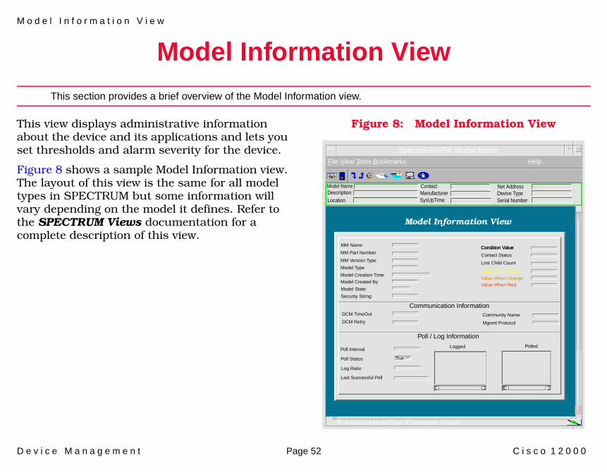
Model Information View
This section provides a brief overview of the Model Information view.
This view displays administrative information about the device and its applications and lets you set thresholds and alarm severity for the device.
Figure 8 shows a sample Model Information view. The layout of this view is the same for all model types in SPECTRUM but some information will vary depending on the model it defines. Refer to the SPECTRUM Views documentation for a complete description of this view.
Figure 8: Model Information View
Model Name ContactDescriptionLocation
SpectroGRAPH: Model Name
File View Tools Bookmarks Help
IP Address of Model Type of Landscape: Primary
ManufacturerSysUpTime
Net AddressDevice TypeSerial Number
Model Information View
MM Name
MM Part Number
MM Version Type
Model Type
Model Creation Time
Model Created By
Model State
Security String
Communication Information
Poll / Log Information
Condition Value
Contact Status
DCM TimeOut
DCM Retry
Lost Child Count
Value When Yellow
Value When OrangeValue When Red
Community Name
Mgnmt Protocol
Poll Interval
Poll Status
Log Ratio
Last Successful Poll
Logged Polled
True
Condition Value

M o d e l I n f o r m a t i o n V i e w
D e v i c e M a n a g e m e n t Page 53 C i s c o 1 2 0 0 0

D e v i c e M a n a g e m e n t Page 54 C i s c o 1 2 0 0 0

D e v i c e M a n a g e m e n t Page 55 C i s c o 1 2 0 0 0

D e v i c e M a n a g e m e n t Page 56 C i s c o 1 2 0 0 0
Index
AAdd an Entry button 30Address
Interface IP 13Physical (MAC) 13
Admin Status 50Applications 18ATM Client Application 33Available 25
BBandwidth 50Bridging
Application Views 39
CccmHistoryRunningLastChanged
Attribute 49Chassis
ID/Serial No. 23Information 23Type 23
Chassis Application 22
Chassis Card View 22Chassis General Information
View 23RAM Information 24ROM Information 23
CiscoChassis
Application Views 22Card View 22General Information View 23
FlashApplication Views 24
Terminal ServerLine View 37Session View 39
Cisco Applications (5127) guide 51Cisco Chassis Card View 22Cisco Chassis General Information
View 22Cisco Network Info 14Cisco Other Info 14Cisco Router Info 14Cisco Syslog Application 51Cisco Traffic Info 14CiscoCDPApp 35CiscoChasApp 22CiscoFlashApp 24CiscoPingApp 29
CiscoTSApp 37CiscSysLogApp 51Config Register 23Configuration
Interface 50Configuration View 43CsEvFormat 8
DDescription 22Discover LANs 46Discover/Reconfigure Control
button 44Discovery Application
Cache Table View 35Interface Discovery Status
Table 36Documentation 5
EECEditor 8EnvMon Application 33
Power Supply Status 34Temperature Status 34
I n d e x I n d e x
D e v i c e M a n a g e m e n t Page 57 C i s c o 1 2 0 0 0
Voltage Status 34event messages 8
FFlash
Memory 25Size 25
Flash Application 24Flash Configuration View 25Flash Copy Operations Table
View 26Flash Device Chip Properties Table
View 25Flash Device Partition Properties
Table View 28Flash Device Properties Table
View 26Flash File Properties Table View 27Flash Miscellaneous Operations
Table View 27Flash Partitioning Operations Table
View 28Flow Control 38
HHardware 6
Revision Level 23Version 22
IIcons
Interface, Device View 12Idle Time out 38IF Address Translation button 44Interface
Detail view 14Type, Device 12
Interface Address Translation Table View 47
Interface Configuration 14Interface Configuration Table 44Interface Icon Subviews Menu 14IP Address/Network Mask 50
LLast Change 50Location 38
MManagement Tasks 11Model
Information 52Types of 6
Model Information 14Modem Control 38
NNetwork
Type 13Network/Host Config button 44Network/Host Configuration
View 47Non-volatile RAM
Size (bytes) 24Used (bytes) 24
NovellRouting
Application Views 21Number
of Chassis Slots 23
OOperation Status 50Optional Applications 21
PPacket Size 50Performance Statistics 41Physical Address 50Ping Application 29Ping Request Entries 29Ping Request Table View 29Port Number, Device 12

I n d e x I n d e x
D e v i c e M a n a g e m e n t Page 58 C i s c o 1 2 0 0 0
Power Supply Status 34
QQueue Application 31Queue Interface View 32Queue Length 50Queue Rotation Interface View 32Queue Statistics View 32
RRAM Information 24Reconfigure Model 46Redundancy and Model
Reconfiguration Options 45ROM
Information 23Monitor Version 23Software Version 23
Running Configuration Changes 49
SSaved Ping Requests 31Secondary Address Panel 14Serial Number 22Session
Table 39
View 39Slot 22SMT
Table 35SMT Table View 35Software
Version 22SPECTRUM Views
documentation 14Speed
In 38Out 38
StatisticsRouting Frame Transmission 42
Status 37Sub-Interfaces 14Syslog Trap Support 51System
CPU RAM (bytes) 24
TTemperature Status 34Term Type 38Terminal Server
Line View 37Session View 39
Terminal Server Application 37Line Configuration View 37Terminal Server Line View 37Terminal Server Session View 39
Thresholds 14TS Session Table 39Type 22, 37
VVoltage Status 34