cis226 software engineering, algorithm design and … · 1.2 the problem ... using uml by perdita...
TRANSCRIPT

BSc (Hons) Computing and Information Systems (External)
CIS226
Software Engineering, Algorithm
Design and Analysis Volume I
Subject guide
Written by Tim Blackwell, Department of Computing, Goldsmiths College, University of
London.

Published 2006
Copyright c© University of London Press 2006
Printed by Central Printing Service, The University of London
Publisher:
University of London PressSenate House
Malet Street
LondonWC1E 7HU
All rights reserved. No part of this work may be reproduced in anyform, or by any means, without permission in writing from the
publisher. This material is not licensed for resale.

Contents
Introduction iii
I Principles 1
1 Software Engineering 3
1.1 What is a good system? . . . . . . . . . . . . . . . . . 3
1.2 The problem . . . . . . . . . . . . . . . . . . . . . . . 4
1.3 Building systems with objects . . . . . . . . . . . . . . 5
1.4 OO design . . . . . . . . . . . . . . . . . . . . . . . . . 7
1.5 Exercises . . . . . . . . . . . . . . . . . . . . . . . . . . 9
1.6 Summary . . . . . . . . . . . . . . . . . . . . . . . . . 9
2 Development Process and Modelling 11
2.1 Iterative and waterfall processes . . . . . . . . . . . . . 11
2.2 Design and modelling . . . . . . . . . . . . . . . . . . 12
2.3 A unified modelling language: UML . . . . . . . . . . . 13
2.4 Fitting UML into a process . . . . . . . . . . . . . . . . 14
2.5 Exercises . . . . . . . . . . . . . . . . . . . . . . . . . . 15
2.6 Summary . . . . . . . . . . . . . . . . . . . . . . . . . 16
II UML 17
3 Use Cases 19
3.1 Requirements capture . . . . . . . . . . . . . . . . . . 19
3.2 The basic technique . . . . . . . . . . . . . . . . . . . 20
3.3 When to use use cases . . . . . . . . . . . . . . . . . . 21
3.4 Exercises . . . . . . . . . . . . . . . . . . . . . . . . . . 21
3.5 Summary . . . . . . . . . . . . . . . . . . . . . . . . . 21
4 Class Diagrams: The basic technique 23
4.1 Class identification . . . . . . . . . . . . . . . . . . . . 23
4.2 Properties . . . . . . . . . . . . . . . . . . . . . . . . . 24
4.3 Properties as code . . . . . . . . . . . . . . . . . . . . 25
4.4 Adding more information to the class model . . . . . . 26
4.5 When to use class diagrams . . . . . . . . . . . . . . . 27
4.6 Exercises . . . . . . . . . . . . . . . . . . . . . . . . . . 27
4.7 Summary . . . . . . . . . . . . . . . . . . . . . . . . . 27
5 Sequence Diagrams 29
5.1 The basic technique . . . . . . . . . . . . . . . . . . . 29
5.2 Advanced techniques . . . . . . . . . . . . . . . . . . . 30
5.3 When to use sequence diagrams . . . . . . . . . . . . . 31
5.4 Exercises . . . . . . . . . . . . . . . . . . . . . . . . . . 31
5.5 Summary . . . . . . . . . . . . . . . . . . . . . . . . . 31
6 Class Diagrams: Advanced techniques 33
6.1 Responsibilities and collaborators . . . . . . . . . . . . 33
6.2 Static operations and attributes . . . . . . . . . . . . . 34
6.3 Aggregation and composition . . . . . . . . . . . . . . 34
6.4 Interfaces and abstract classes . . . . . . . . . . . . . . 34
i

CIS226 Software Engineering, Algorithm Design and Analysis Volume I
6.5 Classification . . . . . . . . . . . . . . . . . . . . . . . 35
6.6 Association classes and visibility . . . . . . . . . . . . . 366.7 When to use advanced concepts . . . . . . . . . . . . . 36
6.8 Exercises . . . . . . . . . . . . . . . . . . . . . . . . . . 37
6.9 Summary . . . . . . . . . . . . . . . . . . . . . . . . . 37
7 State Machine Diagrams 39
7.1 The basic technique . . . . . . . . . . . . . . . . . . . 39
7.2 Implementing state diagrams . . . . . . . . . . . . . . 407.3 When to use state diagrams . . . . . . . . . . . . . . . 41
7.4 Exercises . . . . . . . . . . . . . . . . . . . . . . . . . . 417.5 Summary . . . . . . . . . . . . . . . . . . . . . . . . . 41
8 Activity Diagrams 43
8.1 The basic technique . . . . . . . . . . . . . . . . . . . 438.2 Advanced techniques . . . . . . . . . . . . . . . . . . . 44
8.3 When to use activity diagrams . . . . . . . . . . . . . . 45
8.4 Exercises . . . . . . . . . . . . . . . . . . . . . . . . . . 468.5 Summary . . . . . . . . . . . . . . . . . . . . . . . . . 46
9 Summary of UML modelling techniques 47
III Quality 49
10 Product Quality 51
10.1 Verifying software . . . . . . . . . . . . . . . . . . . . 5110.2 Validating software . . . . . . . . . . . . . . . . . . . . 52
10.3 Testing . . . . . . . . . . . . . . . . . . . . . . . . . . . 5210.4 Exercises . . . . . . . . . . . . . . . . . . . . . . . . . . 53
10.5 Summary . . . . . . . . . . . . . . . . . . . . . . . . . 54
11 Process Quality 5511.1 Project management . . . . . . . . . . . . . . . . . . . 55
11.2 Project planning . . . . . . . . . . . . . . . . . . . . . 56
11.3 Exercises . . . . . . . . . . . . . . . . . . . . . . . . . . 5611.4 Summary . . . . . . . . . . . . . . . . . . . . . . . . . 57
IV Resources 59
12 Analysis and design of a personal 0rganiser 61
12.1 Scenarios . . . . . . . . . . . . . . . . . . . . . . . . . 61
12.2 Use cases . . . . . . . . . . . . . . . . . . . . . . . . . 6112.3 Class Identification . . . . . . . . . . . . . . . . . . . . 62
12.4 UML diagrams . . . . . . . . . . . . . . . . . . . . . . 62
13 Sample examination paper 69
13.1 Advice . . . . . . . . . . . . . . . . . . . . . . . . . . . 69
13.2 Questions . . . . . . . . . . . . . . . . . . . . . . . . . 6913.3 Answers . . . . . . . . . . . . . . . . . . . . . . . . . . 71
ii
Introduction
A while ago I decided to build a small tool shed. I took a trip to thelocal construction yard and bought some wood. Back home, I built a
wooden frame for my shed, sawing the bits of wood as I needed
them. I then nailed sheets of wood to the frame. I left a space for awindow - but I had forgotten to buy any glass at the yard, so I
returned there. I discovered that the yard has ready-made windows,and they looked rather good, so I bought one. Returning home, I
found that the space was too small for the window unit I had just
bought, but this was not a problem because I could easily saw somewood away from the wall panel. And so I continued with my
haphazard construction, returning to the yard from time to time to
buy roof felt, a door, hinges etc. Finally my shed was finished and itis fine. In fact it was so good and I was so proud of my achievement
that I commenced another, larger construction project. I really didneed a bigger kitchen.
After many trips to the construction yard to replace ill-fitting pipesand window frames, after knocking down a newly-built wall
because I had forgotten to install any plumbing, and after countless
other minor re-starts, the kitchen extension was finished, and it wasOK, even though it had taken me months to complete. My next
project was a complete new house, built from scratch in a
neighbouring field.
You know the ending to this domestic tale! My constructiontechniques just could not scale to this big project. The complexity of
the supply of materials (bricks, tiles, concrete, plaster, wood...), the
relationship between the various systems (heating, drainage,electric, gas) and the ramifications of late design change (perhaps
the stairs should really be to the right of the hall - but then the
bathroom needs to be moved to the left of the landing - now thismeans re-routing the water pipes - ...) meant that, if I were lucky,
this project might actually have succeeded, but I would certainlyoverrun and at a very high cost. And would it be the house I actually
wanted?
After some calls I assembled a project team. An architect designed
the house, producing several plans of her design according to my
initial brief. Several rather artistic drawings showed the house fromthe outside so I was able to judge the overall physical design. Other
more formal plans of the interior layout, so I could imagine walking
around inside and visiting the various rooms. At this stage I changeda few things. Still other plans were made for the electrician and the
plumber detailing where the pipes and cables should be fitted.There was even a special plan of the kitchen showing in detail the
work-surfaces and appliances. A surveyor was employed to organise
the supply of materials, builders were employed to perform theconstruction, and engineers checked the work at various stages. A
manager oversaw the whole process.
iii

CIS226 Software Engineering, Algorithm Design and Analysis Volume I
Learning activity
Extract from this tale some general principles of large-scale construction.
Comments on the activity
Large scale construction requires: analysis of the project so that the right thing is built;
early consultation with the client; plans of the project from various perspectives and
levels of analysis; inclusion of pre-built components into the design; management to
ensure that parts of the project are built in the correct order; builders; people to check
the construction, both for accuracy, and for quality.
All of these principles apply to software projects. Here the
constructed artefact is not tangible, but is a logical object. A largepiece of computer code is very intricate, far too complex for any
person to understand. Additional complexity arises from interactionbetween the software and an uncertain physical world, and in
understanding the changing needs of the client. Software, then,
needs to be engineered.
This course is strategically placed at the midpoint of your studies.
You will already have studied a computer language at anintroductory level, corresponding to rudimentary do-it-yourself
skills. Later in your studies you will be developing a larger software
project and this will require a more systematic and scalableapproach. You will not longer be able to sit at the computer and
type your programme code in a trial and error fashion. As theprogramme grows in size you will drown in a sea of complexity.
Your software project will have to be designed, you must become a
software architect. It is the purpose of this course to provide youwith the skills and insights to bridge the gap between small scale
programming and large commercial applications.
The complexity of software is modelled, rather like an architect
models a building, with the use of diagrams. We shall use a
technique that has become an industry standard: the UnifiedModelling Language (UML). Proficiency at UML, along with the
computer languages you have studied, will be amongst the maintransferable skills you will acquire throughout your entire degree
programme.
This subject guide, which covers one half of CIS226, provides an
introduction to software engineering. Part I of the guide begins with
a look at some principles of good software design and how theseprinciples fit into a particular developmental process. The main
topic of this course unit, covered in Part II, examines how to analyseand design software using the Unified Modelling Language (UML).
Part III discusses quality assurance, both of the product and in the
process. Part IV shows a specimen software project and examination.
There are two software projects in this guide: a Personal Organiser
and Space Game. Each chapter of part II ends with an exercise foreach project. These exercises cover the analysis and design stages of
the software life cycle. Algorithm design is an important part of the
implementation phase of a software project, and this is covered inthe second half of this course unit. There will not be any
implementation of Personal Organiser or Space Game. The final
iv
stages of a software project are testing and maintenance, which, in
the absence of actual code, can only be studied theoretically in thiscourse. Later in your studies you will undertake a complete software
project and you will find the ideas and skills of CIS226 invaluable
for the successful completion of this project.
Here are the main topics of this course, arranged to correspond to
the parts of this guide:
I Principles
(a) the role of design and modelling in software development
(b) software development process
II UML
(a) use cases
(b) class, sequence, state machine and activity diagrams
(c) objects and links
(d) compositions, aggregations and dependencies
(e) other UML diagrams and concepts
III Quality
(a) Product quality: verification, validation and testing
(b) Process quality: project management and planning
How to use this subject guide
This subject guide is not a self-contained account, but is a
companion to the course texts UML Distilled by Martin Fowler and
Using UML by Perdita Stevens and Rob Pooley. It is essential that you
obtain these books. This guide is structured in the form of selected
readings from these texts. Learning activities will test your
understanding of the main points of each reading. You are stronglyadvised to attempt these activities as a way of monitoring your own
progress. There are more exercises at the end of each chapter and asample examination paper at the end of the guide.
Each chapter begins with a general statement of the essentialreading for this part, and throughout the text you will find specific
instructions on what to read. It is important that you read the
relevant sections of the course texts when instructed to because textsubsequent to a reading will only make sense in the context of the
reading. The reading will be cited on the following format:
Read UUML/UMLD, Chapter x, heading [omit]
where UUML/UMLD are the title initials of the course texts, x is therelevant chapter (identical to the chapter(s) of the essential reading)
and heading is the chapter section for this directed reading. Eachchapter of either course text begins with a short introduction which
does not have a section heading and is denoted introduction. You
are expected to read all the subsections contained in the section youhave been directed to. Some directions include an omit guard which
tells you to ignore certain subsections or boxes. British English is
used throughout this guide, except in quotations and sectionheadings for the set readings, where the original punctuation and
spelling (which might be American English) is used.
v

CIS226 Software Engineering, Algorithm Design and Analysis Volume I
There is an additional list of books which expand on a number of
topics and you are advised to deepen your understanding byreferring to these additional texts where directed.
Readings
Here are the details of the course texts and additional materials:
Essential
1. UML Distilled (third edition), Martin Fowler, Addison-Wesley,2004
2. Using UML (updated edition), Perdita Stevens with Rob
Pooley, Pearson Education Limited 2000
Supplementary
1. Project-based Software Engineering, Evelyn Stiller and CathieLeblanc, Addison Wesley, 2002
2. Software Engineering (fifth edition), Roger Pressman,
McGraw-Hill, 2000
3. The Mythical Man-Month (anniversary edition), Frederick
Brooks, Addison Wesley 1995
4. Effective Java, Joshua Bloch, Addison Wesley 2001
Aims and objectives
At the end of this course you will be able to
1. Explain the role of software development in the software
life-cycle
2. Produce static and behavioural models of software programs
3. Specify and verify software systems
4. Decompose problems and develop software architectures
5. Implement software models in a structured and efficient way.
These are the major objectives of this course unit. Each chapter also
lists a number of learning outcomes. The learning outcomes breakthe objectives into manageable tasks.
The examination
You will be assessed on your understanding of objectives 1 - 4.
(Objective 5 will be assessed at a later stage of your studies whenyou will be asked to implement a particular project.) The method of
assessment for the complete course unit CIS226 will be one unseen
written exam paper of 3 hours (85 per cent) and four equallyweighted assignments (15 per cent). Software Engineering (the
subject of this guide) will comprise one half of the overall mark forCIS226. There is a sample examination paper for Software
Engineering and advice on exam preparation in the final chapter of
this guide.
vi

Part I
Principles
1

Chapter 1
Software Engineering
Essential reading
Using UML Chapters 1 and 2
All large-scale construction projects follow five main phases of
activity: analysis, design, construction, testing and maintenance.
Software projects are no exception. Software engineering isconcerned both with the phases themselves and also with how each
phase fits into the overall development of the project (in softwareengineering-speak, process).
A large software project runs like this: software architects draw upplans (models) at various levels (abstractions) of analysis. The
models facilitate further analysis and design. Models also serve as
construction guides during the implementation phase and asdocumentation of the end result. To facilitate design and
implementation, ready-made units (components) are used wherever
possible. A project manager oversees the whole process.
A major aspect of software engineering is therefore concerned with
the development process. However, in order to judge how well oursoftware is engineered, we need to have an idea of software quality.
In most domains of engineering, we understand fairly well what asuccessful construction is, and how to achieve it. For example,
bridges should not fall down (and they rarely do), and there are
accepted design principles, construction techniques and qualityassurance assessments. The situation with engineered software is
not so clear, however.
This chapter begins by considering what a high quality software
system should be like and outlines some important designprinciples. Software design with objects is an important
manifestation of these principles and the important aspects of this
paradigm are explained in the remaining sections of this chapter.
1.1 What is a good system?
Read UUML, Chapter 1, What is a good system?.
Stevens and Pooley, the authors of UUML point out that a good
system is surely one that meets its users’ needs. They list five
desirable attributes (namely: usability, reliability, flexibility,affordability and availability) of a good system and consider how
well current systems satisfy these criteria.
3

CIS226 Software Engineering, Algorithm Design and Analysis Volume I
Although successful systems do exist, there are a number of
spectacular failures. These are informally known as software horrorstories and a web search will reveal many sources of information.
Remarkably, many large projects are cancelled, and of those that do
survive, most will significantly overrun their initial planning period.Three quarters of large projects that are actually completed will
ultimately fail!
Learning activity
Suppose that you are managing a large software project which is slipping behind
schedule. Should you employ more people to work on the project? Explain your
answer.
Comments on the activity
The surprising answer to this question is that increasing the size of the team will not
necessarily have any benefit. The reason for this is that as the team increases in size,
more and more of the project’s costs and time are consumed in the overhead of
inter-person communication. In fact, the time needed to ensure that all the information
is available to keep the work consistent can actually extend a project. This idea is
expanded at some length in Fred Brooks’ The Mythical Man Month.
1.2 The problem
Read UUML, Chapter 1, What are good systems like? [omit
Architecture and components, Component-based design: pluggability]
What is behind this gloomy state of affairs alluded to above? Quite
simply, software is extremely complex: there is a limit to how muchwe can understand at one time.
If your only experience of programming has been an introductorycourse on Java, you will have been the sole author of your
programmes and should (in principle) have been able to understandeverything about your code. At first you probably just sat in front of
a screen and typed code directly into an editor, rather like me and
the shed. However, as an application grows in size, thisunstructured approach becomes increasingly hard to sustain - the
programme becomes a single monolithic unit and is just too
complex and difficult to develop and maintain. It seems that sometime must be spent planning how you will code your solution to a
software problem. Then you will implement your solution. Goodquality systems are surely designed.
A number of fundamental design concepts are broadly agreed upon.See Software Engineering by R. Pressman, sections 13.4 and 13.5 for
a full discussion. Above all, the division of software into smaller
modules is universally accepted as the main way to controlcomplexity. There is nothing special about this idea; it is the way
that we seek to understand anything. For example, science works by
modularising the world in a process called reductionism. There is ahierarchy of software modules: from methods to classes to packages
to subsystems. Note however that an excessive modularisation of a
4

Building systems with objects
system could actually increase overall complexity due to the
overhead of integrating very many modules.
Abstraction is the thinning away of detail from a problem domain,
leaving a more general representation. At the highest level ofabstraction, a software solution is provided in broad terms, using
the language of the problem domain. And at the lowest level, the
language is the programming code itself. In between there are manylevels. The software architect will abstract and model the system in
various ways in order to focus on the essential programme elements.
A cohesive module performs a single task and requires little
interaction with other modules in order to accomplish this. Forexample, it is a common dictum that methods should only do one
thing i.e. return or alter a single value with no other side-effects.
Similarly, a cohesive class will represent a single concept, or type ofreal-life object.
Coupling refers to the connectivity between modules, and should bekept to a minimum if the software is to be understood. The
elimination of the notorious go to statement has done much to
reduce ”spaghetti code” and the complexity of a programming unit.There is no such check on modular spaghetti networks however, and
software designers must guard against high coupling.
It is generally agreed that all modules should present a simple,
public interface. The interface defines what tasks the modules canperform, but not how the modules may accomplish this task. These
details are private to the module; a client of the module need never
know them. Each module in a ’good’ system is only linked to a fewothers and every client is not able to know more about the module
than is contained in the interface. This is the important principle of
encapsulation.
A module with high cohesion and low coupling can be re-used,either in later systems, or in other modules of the present system.
The object orientated paradigm supports re-usable modules as we
will later explain. High cohesion and low coupling also mean thatmodules can be replaced without too much disruption to the system
as a whole. They are pluggable. Re-usable, replaceable pluggable
modules function rather like component parts in a mechanism. Thatis why they are called software components.
Learning activity
Write, in your own words, a paragraph on what a good system should be like.
1.3 Building systems with objects
Read UUML, Chapter 2, What is an object?.
This reading relates programming with objects to the reusable,replaceable modules which make good components and ultimately,
we hope, a good system.
5

CIS226 Software Engineering, Algorithm Design and Analysis Volume I
The fundamental module of object orientated (OO) programming
languages is (unsurprisingly) the object. Here we summarise, from asoftware engineering perspective, some properties of objects, and
introduce a small amount of the unified modelling language (UML).
Objects are programming modules that group related data items
together. A set of objects with a similar role in a system is grouped
into a class. Blocks of code which perform common operations onthis data are also grouped together and are maintained by the class.
Objects are supposed to be the software analogue, or representation,
of an actual object or of a concept. In this way, we hope to map thetangible real world of things onto the logical, abstract world of
computer code.
The class is an object factory, responsible for making however many
objects the system requires. (An object can be referred to as aninstance of a class.) The state of an object is the value of all the
variables in that object and the behaviour of an object is the way
that an object responds to messages. In the OO world, a system is acollection of objects which are sending messages to each other in
order to accomplish a certain task.
An example of an object message is:
resetTime( newTime: Time )
This message is written in UML notation. Here, newTime is an objectof type Time i.e. an instance of the Time class. Notice that the
message resetTime( newTime: Time ) is language independent;
we just expect that a myClock object will accept and respond to thismessage. In Java, we would ensure that an Time object would
accept this message by implementing a method in TimeTime with
the signature:
public void resetTime( Time newTime )
The class of an object also defines its interface. In the Clock
example, myClock is an object of class Clock. Clock’s public
interface might specify that each Clock object should providereset-time and report-time operations. A Clock object will also have
a private time attribute. Private attributes are only available to theobject itself: clients’ of Clock cannot access time directly. Instead,
they can only ask the time by sending the message report-time to a
Clock object. This is known as data-hiding. In contrast, a publicattribute or operation is accessible by any client. Hidden-data is
often accessed using specific accessor (getters and setters) methods.
Objects from the same class have the same interface. The public andprivate interface to Clock might be:
-time : Time
+ reportTime() : String
+ resetTime( newTime: Time )
where the symbols + and - refer to public and private visibility.
Learning activity
1. What is an object’s interface? What is the difference between a public and a
private interface?
6
OO design
2. Why bother grouping similar objects together into a class?
3. Write, in pseudo-Java, a class outline for Clock based on its declared interface.
Comments on the activity
1. See section UUML, What is an object [subsection: Interfaces].
2. See the digression UUML, What is an object? [subsection: Digression: why have
classes?]. A basic answer to the problem of maintaining consistent copies of any
software artefact is to structure code so that no copies are necessary! For
example, all my Clock objects need to be reset. It’s far easier to maintain (i.e.
revise and re-use) a single reset method in the class myClock. A further and
more technical point is that a class can be thought of as a type, and the language
compiler can spot possible errors when type-checking.
3. The pseudo-Java code, shown below, is a bridge between the design and the
implementation phases of a software project.
class Clock
private Time time
public String reportTime()
return time.toString()
public void resetTime(Time newTime)
time = newTime
Read UUML, Chapter 2, How does this relate to the aims of the
previous chapter?.
The previous chapter proposed that reusable, replaceable,
component-like modules will lead to reduced development time andcost, ease of maintenance and greater reliability. OO is expected to
deliver on these counts, but objects themselves do not make good
modules, because there can be many similar objects in a system, andthe requirement to ensure consistency between them would be a
very high price to pay. A house is made from many bricks but asingle Brick class provides the necessary generalisation.
Another benefit of OO is that it is natural to objectify the world, sothat an OO system can provide a better match between abstract
computer code and the problem domain of the customer. An object
model can help engineers’ in capturing requirements, followingchanges in user requirements and allowing for more naturally
interacting systems.
OO, of course is not the only possible approach, but it is one that
takes modularity, encapsulation and abstraction as fundamental.
1.4 OO design
Read UUML, Chapter 2, Inheritance.
Inheritance, polymorphism and dynamic binding are the three
features that make OO special.
7
CIS226 Software Engineering, Algorithm Design and Analysis Volume I
Inheritance is an important concept in OO design and you should
make sure that you understand the explanations given in thisreading. Notice in particular how a subclass can inherit attributes
and operations from its superclass, a subclass can add extra
attributes and operations, and a subclass may override somesuperclass methods. (Less usefully, a subclass may also shadow
superclass variables.)
Apart from the direct advantage of code re-use, inheritance implies
another defining feature of the OO paradigm. A subclass object can
be freely substituted for its superclass parent. This means that anobject can have any one of several types. The ability of an entity to
exist in different forms is called polymorphism.
Since methods may be overridden in sub-classes, what code should
be executed as the result of some message? For example, aLecturer class can be sub-classed by a DirectorOfStudies class
with the overridden method canDo( Duty duty ). In the following
pseudo-code
for each o in lecturers
o.canDo( seminarOrganisation )
lecturers is a list of Lecturer objects, and includes aDirectorOfStudies object, o is a specific object selected from this
list and canDo( seminarOrganiisation: Duty ) is an operation
on Lecturer objects. Note also the dot notation signifies messagesending: o is the recipient of the message cando(
seminarOrganisation ). When the program execution reaches the
DirectorOfStudies object, the overriden canDo method is invoked,as we would expect. The runtime selection of the correct method
due to a specific message is known as dynamic binding.
Learning activity
Inheritance clearly favours code re-use, and it would therefore appear to be a desirable
feature of OO. Do you think that inheritance leads to greater or less encapsulation?
Comments on the activity
Item 14 of Effective Java by Joshua Bloch warns against inheritance across package
boundaries. A subclass depends on the implementation details of its superclass,
clearly in conflict with the principle of encapsulation. Composition is a better solution -
we shall return to this in a later chapter.
Read UUML, Chapter 2, Polymorphism and dynamic binding.
Clearly, polymorphism promotes code re-use. But polymorphism
also makes code more flexible. For example, the Java classes Vector
and ArrayList both implement the Java interface List. Rememberthat an interface, in general, defines what tasks a module can do,
but not how it may do it. In Java, an interface type is a
programming implementation of this general notion: Vector andArrayList implement certain methods which are specified by the
List definition. Hence they share the same public interface.
8

Summary
Furthermore, an interface defines a type which all implementing
classes share. For example, wherever a Vector is instantiated
Vector subscribers = new Vector();
we can use a List object:
List subscribers = new Vector();
and a Vector instance method such as add( Object o ) will still
work:
subscribers.add( newSubscriber );
This is more flexible because we can later switch implementations
List subscribers = new ArrayList()
and all the surrounding code will still work. Item 34 of Effective Java
explains this point in some more detail.
1.5 Exercises
1. Would individual objects make good modules?
2. Supporters of OO claim that a major benefit of this paradigm is
that it is inherently natural to look at the world in terms ofobjects. Why should this be beneficial for software design?
3. Suppose that OO enables us to build a good system. How muchof this is due to the intrinsic nature of OO techniques?
Answers
1. No. See UUML, Chapter 2, How does this relate to the aims of the
previous chapter? [first three paragraphs].
2. The short answer is that the system can better match the users’
model of the world. But you should try to understand whysoftware architects consider this to be desirable.
3. If OO succeeds, it is because this paradigm takes modularity,encapsulation and abstraction as fundamental.
1.6 Summary
After studying this chapter you should be able to
state what a high quality software system should be like and
comment on to what extent we have such systems
state the basic problem faced by software developers
list and explain the fundamental design concepts of software
engineering (modularity, abstraction, high cohesion, low
coupling, simple public interfaces, encapsulation, components)
explain what software objects are, and how they communicate
use UML to specify a class interface
translate object messages into Java methods, and write a class
skeleton based on a declared interface
9

CIS226 Software Engineering, Algorithm Design and Analysis Volume I
list and explain the three special features of OO (inheritance,
polymorphism, dynamic binding)
10
Chapter 2
Development Process and Modelling
Essential reading
UML Distilled, Chapters 1-2
Using UML, Chapter 4
Additional reading
R. Pressman, Software Engineering, a Practitioner’s Approach, Chapter 2
The first chapter argued by analogy that software, like any other
engineering project, proceeds by phases of development. The phasesfit together into a process. In this chapter we consider the
development process in more detail. We also look again at the
fundamental problem of software systems - the intangibility andcomplexity of computer code. Good design, we have discovered, is
modular. But how do we arrive at these modules? We can’t playwith a lump of plasticine or sketch pictures in order to brainstorm
new ideas. However, the system must be modelled in some way. We
introduce software modelling languages and the chapter finishes bydemonstrating how the most prevalent modelling language, UML,
integrates back into the developmental process.
2.1 Iterative and waterfall processes
Read UMLD, Chapter 2, Iterative and Waterfall Process.
The iterative and waterfall methods are the two major categories of
software development processes. Both methods agree that the
process must be subdivided into phases. The waterfall emphasisesdiscrete activities that must be completed sequentially. And just like
a real waterfall, back flow is impossible (or at least exceptional).Iterative techniques break the project down into chunks of
functionality, called iterations. Each iteration is a complete life-cycle:
analysis, design, implementation and testing. Each iteration outputsa system of production quality, even if it is not actually released at
this stage. Time boxing forces an iteration to be of fixed duration,
even at the expense of slipping functionality. Generally speaking it isbetter to slip a function rather than a date because the team can
then learn just what the most important functional requirementsactually are.
11

CIS226 Software Engineering, Algorithm Design and Analysis Volume I
Learning activity
Which process is recommended by the OO community? Why is this?
Comments on the activity
See UMLD, Chapter 2, Iterative and Waterfall Processes [last half of this section].
(Martin Fowler, the author of UMLD recommends "You should use iterative
development only on those projects that you wish to!")
2.2 Design and modelling
Read UUML, Chapter 4, Defining terms [omit: Process and Quality].
As we have mentioned before, a model is an abstract representation
of a specification, a design or a system. The model itself is usuallyrepresented visually, as a diagram, but can be textual. The model is
precise according to the implicit point of view. Room plans, wiring
diagrams, elevations and other architectural plans strip awayunnecessary detail in order to focus more clearly on what they are
representing. The modelling language has syntax and semantics,
just as a natural (spoken) language does. The unified modellinglanguage, UML, is quickly becoming the lingua franca of software
architects. One reason for this is that the language is very flexibleand is not tied to a particular process.
Learning activity
What are the attributes of an ideal modelling language?
Comments on the activity
A modelling language should be expressive, easy to use, unambiguous, supported by
tools and widely used - see the list of points in UUML, Chapter 4, Defining terms
[subsection: Why a unified modelling language?].
Read UUML, Chapter 4, system, design, model, diagram.
The developmental process will produce (we hope) a collection of
programmes which work in an appropriate environment to fulfil the
users’ needs. The architecture of this system abstracts away manydetails and embodies just how the system should be built.
The plans for a house do not include each brick, each floorboard andevery electrical socket, but they do show the relative positions of the
walls, floors and ceilings, the electrical wiring, the landscaping of
the garden...There are many plans, each one is incomplete in itself,but taken together they describe the project at just the right level of
detail for the builders, electricians, joiners and landscape gardeners.
12
A unified modelling language: UML
Plans are roughly analogous to models in software engineering.
Many models are needed even with a simple design; it is impossiblethat a single diagram can capture every design aspect. There are
three groupings of software models, a use case model, a static or
structural model and a dynamic or behavioural model. A buildingplan may be drawn from different perspectives. Similarly, four
software ”views” have been suggested: logical, process,
developmental and physical. A design requires several models, andeach model might require several diagrams from various views, and
all of these must be consistent.
We are now ready to begin our study of UML.
2.3 A unified modelling language: UML
Read UMLD, Chapter 1, What Is the UML?.
The fundamental imperative behind all graphical techniques is thatprogramme code is not at a high enough abstraction to promote
meaningful discussions about design. UML is a family of graphicalnotations, unified by a single meta-model. These notations help in
describing and designing OO software. UML is an open standard,
controlled by the Object Management Group, and is a unification ofmany pre-existing OO graphical techniques.
Read UMLD, Chapter 1, Ways of using UML [omit Model Driven
Architecture and Executable UML].
This reading suggests that UML can be used in different ways. Thisis because people use older graphical modelling languages in
different ways, and that legacy has passed to the newer, unifiedlanguage. The three uses or modes outlined are sketching,
blueprinting and programming. One criticism of the blueprinting is
that it takes too much time to prepare and that textual languagesare already very effective for most programming tasks. In
programming mode, UML becomes the source code, and this mode
demands very sophisticated tools.
Learning activity
Write a few sentences on each of the three modes of use of UML.
As well as the three modes of use, there are two perspectives, the
software perspective and the conceptual perspective. Some toolswill turn a UML diagram into source code. This is very much a
software perspective. Alternatively, in the conceptual perspective,
the diagrams are language independent representations ofstructures and relationships.
Read UMLD, Chapter 1, UML diagrams.
Tables 1.1 and 1.2 of UMLD show classifications of the thirteen
diagram types in UML 2.0. You do not need to learn these tables!They will be useful, though, for you to refer back to as we introduce
various diagrams in part II of this guide. The UML authors’ do not in
13
CIS226 Software Engineering, Algorithm Design and Analysis Volume I
fact see the diagrams as the central part of UML and as a result the
diagram types are not rigid and there is much flexibility in their use.
Read UMLD, Chapter 1, What is legal UML?.
Most people regard that the UML rules are descriptive rather than
prescriptive. This means that we infer language rules by looking at
how other people have used them, just as we have all done inlearning our own first spoken language. The UML does have a
standard, although even this is imprecise because UML is so
complex. Information may be suppressed in UML, so that nothingcan be inferred from the absence of any particular detail in a
diagram. But most important, it is better to have good design ratherthan strictly legal and precise UML.
Read UMLD, Chapter 1, The meaning of UML.
There is no formal definition of how UML maps to any particular
programming language. The meaning of UML (within the sketchmode) is to provide a rough idea of what the code will look like. We
can trust the bricklayer to actually make the wall, but a plan tells
her where to put it.
Read UMLD, Chapter 1, Where to start with UML.
Luckily, Fowler recommends that we don’t need to use all thirteen
UML diagrams! A team will work well with just a subset of UML.
The most common and useful diagrams are class and sequencediagrams. Chapter 9 makes further suggestions.
2.4 Fitting UML into a process
Read UMLD, Chapter 1, Fitting the UML into a process [omit
Documentation].
This section of UMLD suggests which types of diagrams are useful in
the analysis and design phases, and also for documentation. The
section also discusses how to use UML in sketch or blueprint mode.
Learning activity
Contrast the different uses of UML in the waterfall and the iterative process.
Comments on the activity
In the waterfall approach to development, the diagrams are prepared as part of each
phase and are included in the end of phase documents. UML is used for blueprinting,
and the diagrams are definitive.
In the iterative process, the UML diagrams may be sketches or blueprints, but they may
be modified at each iteration. The analysis diagrams will be drawn in the iteration
preceding the iteration that adds functionality to the software. Blueprint design can be
made early in the iterations for targeted, principal functionality, and any iteration can
make changes to existing models rather than building a new model. The model itself is
not reworked.
14

Exercises
2.5 Exercises
1. What are the similarities and differences between the waterfalland iterative development processes?
2. How can you tell if a process is truly iterative?
3. A project manager is overheard saying ’This iteration’s buggy,
but we’ll clean it up at the end’. What software development
process is being used on this project? Explain your answer.
4. (a) What is code rework?
(b) In many domains, such as manufacturing, rework is seen as
being wasteful. Is this true in the software domain?
(c) Which technical practices can make rework more efficient?
5. (a) Which UML techniques are useful in the requirements
analysis phase?
(b) What is the main objective during this phase?
(c) How does this impact on the UML techniques?
6. Which diagrams are useful during the design phase, and how
are they used?
Answers
1. Two paragraphs summarising the material in UMLD, Chapter 2,
Iterative and Waterfall Processes [first page] would be a good
answer. Diagrams similar to R. Pressman, Software Engineering:
A Practitioner’s Approach, Figures 2.4 and 2.7 will gain bonus
marks.
2. Each iteration must produce tested, integrated code that is of (or
close to) production quality. The test is that any iteration thathas not been scheduled for release, could in fact be released.
3. A waterfall process, because the manager admits the current
iteration is not of production quality, contrary to the definitive
test for a genuine iterative process (see above answer).
4. (a) Rework means that existing code is revised, possibly evendeleted
(b) Far from being wasteful, code rework saves time (and hencemoney) in the long run because it is rarely a good idea to
patch badly designed code.
(c) Automated regression tests, re-factoring and continuous
integration.
5. (a) See UMLD, Chapter 2, Fitting the UML into a Process
[subsection: Requirements Analysis].
(b) Use cases, class, activity and sequence diagrams are all
useful in this phase.
(c) The overriding aim is communication between architects
and users (just as in house building projects), so UML rules
may have to be broken because clients - who are thedomain experts - will not necessarily be at all familiar with
software engineering.
15

CIS226 Software Engineering, Algorithm Design and Analysis Volume I
6. See UMLD, Chapter 2, Fitting the UML into a Process [second
page]. Class diagrams - these show the classes and how theyinterrelate. Sequence diagrams model scenarios (scenarios will
be explained in a later chapter, but basically they are short
stories illustrating how a user may interact with the system).Package diagrams - these show the large-scale organisation of
the software. State diagrams are useful for any class with a
complicated life history. Deployment diagrams show thephysical layout of the software.
2.6 Summary
After studying this chapter you should be able to
list the four phases of software development (analysis, design,
implementation, testing)
explain why developmental phases must be managed in aprocess
describe and distinguish the waterfall, iterative and agile
development processes
explain the importance of modelling and finding a goodmodelling language
list the features of a good modelling language (expressive, easy
to use, unambiguous, supported by tools, widely used)
state the three groups of software models (use case, static or
structural and behavioural or dynamic)
state and explain the three modes of use of UML (sketch,
blueprinting and programming)
explain the difference between a software perspective and a
conceptual perspective
recommend types of diagrams for the analysis and design phases
16

Part II
UML
17


Chapter 3
Use Cases
Essential reading
UML Distilled Chapter 9
You have been introduced to the idea of a modelling language. PartII of this guide is largely devoted to the unified modelling language
(UML). However, we begin with a technique that UML does notstandardise, and whose value derives from text rather than
diagrams.
3.1 Requirements capture
The hardest single part of building a software system is deciding
precisely what to build. No other single part of the conceptual work is
as difficult as establishing the detailed technical requirements,
including all the interfaces to people, to machines, and to other
software systems. No other part of the work so cripples the resulting
system if done wrong. No other part is more difficult to rectify later 1. 1Frederick Brooks in No Silver Bullet:
Essence and accidents of software
engineering IEEE Computer, pp.
10-19, 1987The essential phases of software development are: requirements
analysis, design, implementation, testing and maintenance. Thesephases are common to all software development processes, but each
process differs in the duration, completeness and sequence of thesesteps. But all processes agree on the very first step, namely deciding
what needs to be built.
Learning activity
Why do you think deciding precisely what needs to be built is so difficult? What are the
ramifications for not making these decisions?
Comments on the activity
The important thing is not to decide what to build, but to decide what precisely to build.
This is hard because
the client might only have a vague and unrealistic idea of what they want
the software engineers are not experts in the application domain
shifting requirements as the project develops
19
CIS226 Software Engineering, Algorithm Design and Analysis Volume I
3.2 The basic technique
The aim of requirements analysis is a description of how the system
should behave in certain situations, i.e. a set of functional
requirements. Use cases are a technique for capturing theserequirements. The use cases describe typical interactions between
the users and the system. This narrative is built from scenarios. Ascenario is one thing that might happen, and several scenarios, all
tied together by a specific user goal, constitute a use case.
The users of the system are called actors, a mistranslation of the
Swedish word for role. An actor is a role that a user has when
engaging with the system. Actors need not even be people: anexternal computer system could also be an actor.
Read UMLD, Chapter 9, Content of a Use Case.
Figure 9.1 of UMLD shows a possible format of a use case. UML
itself does not specify a standard. Notice that the use case is textualrather than diagrammatic. Each statement or step is an element of
the interaction between the actor and the system, showing theintention, but not the mechanism. Each step may suggest alternative
situations, and these are logged as extensions to the use case.
Sometimes a sequence of steps can occur in other use cases as well.These steps can be factored out and replaced with a single more
complex step. Pre-conditions, guarantees and triggers can also be
added to use cases, but the aim should always be for simplicity.
Learning activity
1. What is a scenario, and why is it used?
2. What is the relationship between scenarios and use cases?
Comments on the activity
1. A scenario is a sequence of steps describing an interaction between the user and
the system. It is written as a paragraph of normal text. They are used for
requirements capture. Since they are textual, they are easily understood by the
domain expert. A number of scenarios will eventually comprise a single use case.
The use case is the principle UML expression of system requirements.
2. Several scenarios may share a single goal, but in some of them the user does not
succeed in achieving this goal. These scenarios, linked by a common user goal,
become a single use case. The main success scenario becomes the main body
of the use case, the other scenarios enter the use case as extensions.
Read UMLD, Chapter 9, Use Case Diagrams.
As you can see in Figure 9.2, UML does specify a diagram for usecases, but really such things serve best as a table of contents to the
textual descriptions. The diagram shows the actors, the use cases,and any inclusions.
Read UMLD, Chapter 9, Levels of Use Cases.
20

Summary
The reading distinguishes business use cases from system use cases.
The system use case concerns a (relatively short) interactionbetween an actor and the system. These are ”sea-level” use cases.
Interactions that have complex ramifications for the entire business
are at a higher (kite) level. And use cases that only exist becausethey are included in other level 1 cases are at fish level.
3.3 When to use use cases
Read UMLD, Chapter 9, When to Use Use Cases.
Use cases help us to grasp the basic functional requirements of thesystem and should be generated early in the project. Later,
immediately prior to implementation, more detailed versions of
these cases can be derived. The use case diagram is of little valuecompared to the textual specification. As with all good UML, always
strive for simplicity and clarity.
3.4 Exercises
1. Your development team has been asked to develop a PersonalOrganiser. The organiser should allow users to enter
appointments in a calendar, receive alarms and maintain an
address book of contacts. You might be able to think of otherdesirable functions. To begin this project, write some scenarios.
Form a few simple use cases from these scenarios and draw a
use case diagram. Now, in a mini-iteration, study your use casesand include any pre-conditions, guarantees and triggers that
might seem appropriate.
2. Your development team has been contacted by a client who
wishes to produce a Space Game. This game will be based on
classic video games such as Space Invaders, Galaxians andAsteroids as a single application. See
http://www.spaceinvaders.de/ for information on Space
Invaders and links to other retro arcade games.
To start, develop a set of scenarios and use cases for SpaceInvaders. If you have time, develop some use cases for at least
one more game. Are there common features? Can you now
develop some use cases for a generic Space Game?
3.5 Summary
After studying this chapter you should be able to
state what a scenario and a use case are
explain the relationship between a use case and a scenario
compose scenarios and use cases for software projects
draw a use case diagram
understand the different levels of use cases
add common information such as pre-conditions, guarantees,
triggers to a use case
21

CIS226 Software Engineering, Algorithm Design and Analysis Volume I
be able to factor out common steps from use cases and
represent this on a use case diagram
know when (at what stage of the software developmentprocess) to compose and amend use cases
22

Chapter 4
Class Diagrams: The basic
technique
Essential reading
UML Distilled Chapter 3
Using UML Chapter 5
Read UMLD, Chapter 3, Introduction.
The class diagram is a very widely used modelling technique. A classdiagram describes the types of objects in the system and the static
relationships between them. This chapter shows you the basic
techniques of class modelling. We begin by asking: how do we knowwhich classes a system might have in the first place?
4.1 Class identification
Read UUML, Chapter 5, Identifying objects and classes.
The objectives for any software project are to minimise expense anddevelopment time whilst maximizing system maintainability and
adaptability. These objectives are often in conflict, but they may be
met if the class model provides all required system behaviours, andif the classes represent enduring domain objects, irrespective of the
particular functionality required during development. A Book classin a library system represents just such a domain object.
Any technique that leads to a good class model is satisfactory. It isunlikely that you will find all the correct classes at the first iteration.
The most important domain objects (such as books, catalogue,
library member) should be easy to spot, because these belong to theproblem. More elusive, though, are other classes that will have to be
introduced in order to help solve the problem. A common techniqueis noun identification. Start with the requirements specification and
make a candidate list of all nouns and noun phrases. Then eliminate
inappropriate classes, and rename, if necessary the remainingclasses. UUML lists some reasons why a candidate class might be
eliminated and you should study this list carefully.
Ultimately, what you will be left with is a list of tangible or
real-world things (book, journal, catalogue) and less tangible things
such as roles (librarian, library-member). Ideally a software object,as generated by a class, represents a real-world object. This
correspondence between the world and its representation as code
23

CIS226 Software Engineering, Algorithm Design and Analysis Volume I
helps us to conceptualise the system and deal with complexity. The
system itself is the sum total of all the objects, and of all theirinteractions. OO design seeks to avoid the monolithic top-down
approach where a single module knows and does everything and
you should be careful that your own architecture does not fall intothis trap, for example by using a single object to represent the core
of the system.
Learning activity
1. What is so bad about top-down design?
2. Suppose you are refining a candidate class list. Under what criteria would you
reject any candidates?
Comments on the activity
1. Top-down systems with a single monolithic class are difficult to maintain and have
built-in assumptions about how the system will be used.
2. An inappropriate class will have one or more of the following undesirable
attributes:
redundancy
vagueness
an event or an operation
too abstract, not representing an object in the problem domain
outside the scope of the system
an attribute with no interesting behaviour
4.2 Properties
Read UMLD, Chapter 3, Properties.
Properties are the structural features of a class, and appear on the
class diagram as an attribute or an association. The attribute appearsinside the class box, and only the name of the attribute is necessary.
At the first attempt, you might wish to restrict attribute descriptions
in your class diagram to name:type, e.g. price:Money. This meansthat price is an object of class Money.(In fact there are other
possibilities, because an object’s type is quite a complicated thing.)
An association is a solid line between classes, directed from the
source to the target class. In this case, the name of the attributeappears at the target end of the line. In Figure 3.3, dateReceived,
lineItems and isPrepaid are properties of Order, represented in
the diagram by associations. Following the advice in this reading,you may wish to reserve associations and class boxes for the most
significant classes - it all depends on what you want to emphasise by
any particular diagram.
Learning activity
Study the associations in Figure 3.3.
24

Properties as code
1. How many orders may be made on any day?
2. Can we have an order line without an order?
Comments on the activity
1. Any number, including none at all (consider the association between the source
Date and the target Order).
2. No. The OrderLine (source) - Order (target) association has multiplicity 1.
Any number of order lines are associated with one, and only one, order.
4.3 Properties as code
Read UMLD, Chapter 3, Programming Interpretation of Properties.
A simple way of implementing properties in code is with privatedata fields. Clients of the class can then retrieve or alter this data
with public getter and setter methods. However, the property canalso be computed rather than stored. In this case a getter method
could calculate the data (e.g. multiply the number of items by their
unit price). Multi-valued attributes are coded with a collection, andin this case you will certainly choose to update an item with a setter
method. An alternative, and dangerous, implementation might
return the entire collection to the caller.
The class skeleton for Order shows how the lineItems property can
be implemented by a HashSet, which is a particular sort ofunordered collection, or set. In contrast, this same property is
marked as ordered in Figure 3.3, and it would be implemented by aList or an Array. In practice, for consistency, the class diagram and
class skeletons should really agree.
Note that the getter/setter methods will retrieve/alter a single item
from lineItems, rather than pass the whole set to the requesting
client object. The client would not need to know that line items arestored in a list, or an array; all the client wishes to do is inspect an
item. This is the essence of encapsulation.
Learning activity
Why should you be afraid of classes that are nothing but a collection of fields and their
accessors?
Comments on the activity
OO design is concerned with objects that have rich behaviour. Objects are not just
parcels of data, but also have operations and behaviour. A heavy use of an object’s
accessors indicates that some behaviour should be moved to this object.
25
CIS226 Software Engineering, Algorithm Design and Analysis Volume I
4.4 Adding more information to the class model
Read UMLD, Chapter 3, Multiplicity.
The multiplicity of a property is the number of how many objects fill
this property. Make sure that you understand the meaning of the
notation [1], [0..1], [0..2] etc. and [*].
Read UMLD, Chapter 3, Bidirectional Associations.
The bidirectional association, signified by navigability arrows at
either end, refers to a pair of properties that are linked together, as
in the Person - Car association. Navigating from Car to Person andback again returns us to the same car. Implementing bidirectionally
is difficult due to synchronisation of the data.
Learning activity
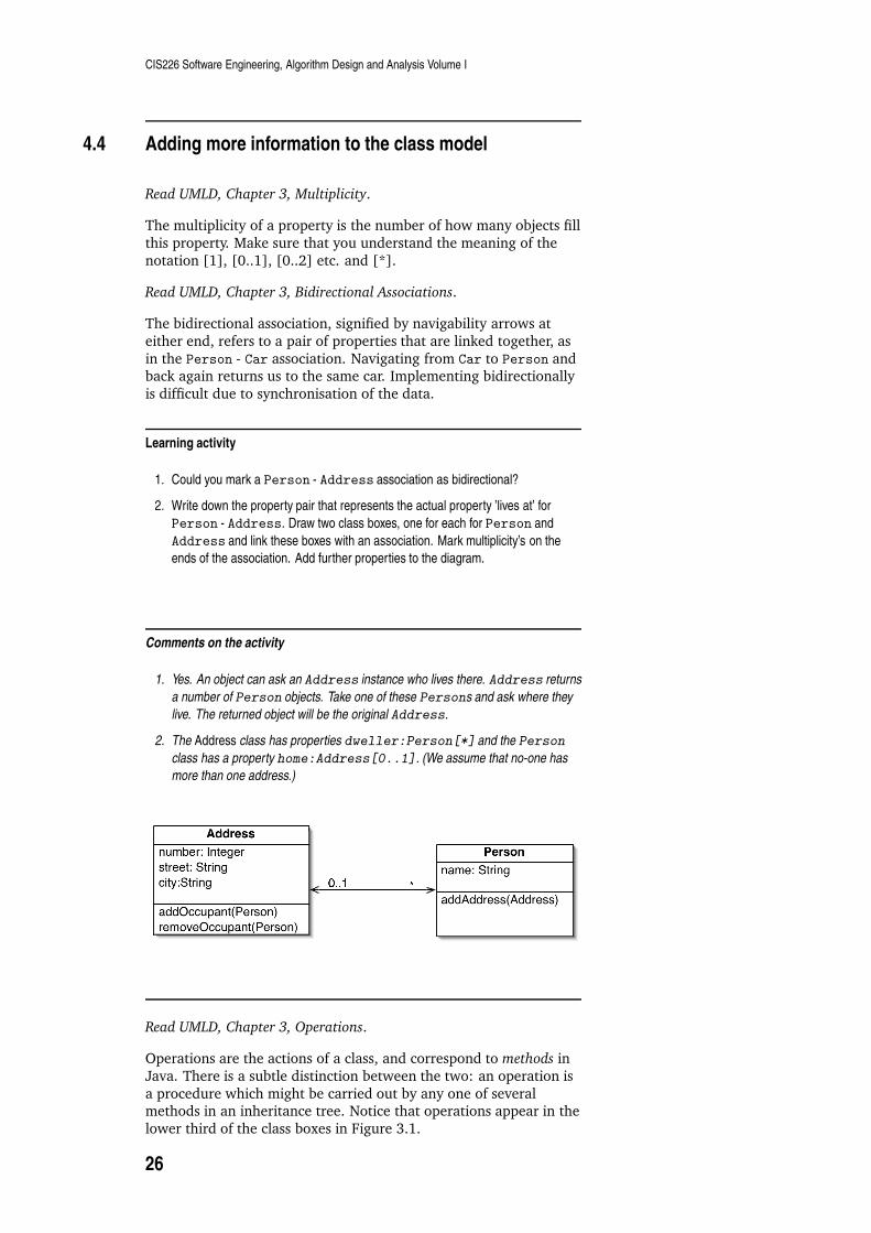
1. Could you mark a Person - Address association as bidirectional?
2. Write down the property pair that represents the actual property ’lives at’ for
Person - Address. Draw two class boxes, one for each for Person and
Address and link these boxes with an association. Mark multiplicity’s on the
ends of the association. Add further properties to the diagram.
Comments on the activity
1. Yes. An object can ask an Address instance who lives there. Address returns
a number of Person objects. Take one of these Persons and ask where they
live. The returned object will be the original Address.
2. The Address class has properties dweller:Person[*] and the Person
class has a property home:Address[0..1]. (We assume that no-one has
more than one address.)A d d r e s sn u m b e r : I n t e g e rs t r e e t : S t r i n gc i t y : S t r i n ga d d O c c u p a n t ( P e r s o n )r e m o v e O c c u p a n t ( P e r s o n ) P e r s o nn a m e : S t r i n ga d d A d d r e s s ( A d d r e s s )0 . . 1 *Read UMLD, Chapter 3, Operations.
Operations are the actions of a class, and correspond to methods in
Java. There is a subtle distinction between the two: an operation is
a procedure which might be carried out by any one of severalmethods in an inheritance tree. Notice that operations appear in the
lower third of the class boxes in Figure 3.1.
26
Summary
UML distinguishes between query and command operations.
Technically, a query does not change the observable state of anobject. A useful programming tip is to separate commands from
queries by ensuring that commands do not return any value to the
caller.
Read UMLD, Chapter 3, Generalization.
Generalisation means that two objects of different types may be
freely substituted for each other. The obvious OO mechanism is
inheritance. Subclasses of a parent inherit all the features of thatparent, and may override any method of the parent. In general, a
subtype can replace a super-type in any code block and theprogramme will still function (although the output may be different,
of course). This is a manifestation of the OO principle known as
polymorphism. A subclass is therefore a subtype. Differentlanguages might have additional mechanisms for sub-typing, for
example interfaces in Java. Interfaces are studied in Chapter 5 of
UMLD.
4.5 When to use class diagrams
Read UMLD, Chapter 3, When to Use Class Diagrams.
Class diagrams are the single most important modelling idea in UMLand you will use them all the time. However they can be very
detailed. Too much detail can detract from the underlying purpose
of the diagram. It is best therefore to start simply and add extrainformation only when necessary. Don’t draw models for everything.
A few class diagrams should cover the breadth of the system. Eachclass diagram should be used in conjunction with a behavioural
diagram so that the dynamic relationship between objects can be
grasped.
4.6 Exercises
1. Examine the scenarios and use-cases that you wrote for the
Personal Organiser (Section 3.4). Construct a candidate class
list. Refine this list by elimination and renaming until you areconfident that you have discovered the base classes. Now
construct a class diagram for one or more of the use cases thatyou have previously identified (see Section 3.4).
2. Draw up a class list for Space Game. Refine this list and
construct a class diagram for one or more of the use cases that
you have already identified in Section 3.4.
4.7 Summary
After studying this chapter you should be able to
draw up a candidate class list from a requirements document
state what characteristics a candidate class should have
27

CIS226 Software Engineering, Algorithm Design and Analysis Volume I
recognise class boxes, attributes and associations on a class
diagram
be able to use the full textual description of an attribute
understand how an association on a class diagram relates to
message-passing between objects
draw simple class diagrams
write class skeletons for simple class diagrams
add multiplicity’s to associations
use, where appropriate, a bi-directional association
distinguish command operations from query operations
state the meaning of subtype, super-type and inheritance
28

Chapter 5
Sequence Diagrams
Essential reading
UML Distilled Chapter 4
Class diagrams show the static structure of a system and are
classified as Structure Diagrams in UML (see Fig 1.2 of UMLD). Butdynamic object message passing is the fundamental way that an OO
system executes any particular behaviour. Interaction Diagrams
describe how objects collaborate, and the most widely-used is theSequence Diagram. The sequence diagram illustrates a single
scenario and depicts relevant objects and messages. This chapter
will show you how to construct sequence diagrams and add featuressuch as creating and deleting participants and asynchronous and
synchronous calls. There will also be an important example ofdecentralised control, a defining characteristic of the OO paradigm.
5.1 The basic technique
Read UMLD, Chapter 4, introduction.
Figure 4.1 of this reading shows a sequence diagram for thescenario Calculate Price for a business system. Note the presence
of participant boxes at the head of each lifeline. Although aparticipant is essentially an object, the name of the participant
should not be underlined. (Object names are usually underlined in
UML). Also note that messages are shown as lines with filled arrowheads and are also named. The participant activation bar shows
when a participant is active, corresponding directly to when the
object’s methods are currently being executed by the CPU (on thestack). Return arrows can be used for each method call, and the
found message begins the interaction. Finally, this diagram showshow an object can call a method on itself. The order object makes
such a call with the message calculateBasePrice.
Learning activity
What feature of Calculate Price is not evident in Figure 4.1? What features of
the interaction are well illustrated by sequence diagrams?
29
CIS226 Software Engineering, Algorithm Design and Analysis Volume I
Comments on the activity
This basic sequence diagram does not show when messages have to be repeated.
Sequence diagrams are not good at describing algorithmic details such as loops and
conditionals (although these can be incorporated) but they do excel in their depiction of
calls between participants, and the particular processing that each participant has to
undertake.
Look now at Figure 4.2, and carefully study Fowler’s account of this
diagram which accomplishes Calculate Price through distributedrather than central control. You should certainly aim to construct
sequence diagrams that look more like Figure 4.2 than Figure 4.1,because your system architecture will then reflect the OO paradigm,
which is to use lots of little objects and lots of method calls, rather
than a single module that does the bulk of the work.
Learning activity
What are the advantages and disadvantages of distributed control?
Comments on the activity
The main advantage is that the effects of change are localised. Data and behaviour
that accesses this data are contained in one place, and this reduces the complexity of
system change and enhances system development and maintenance. Another
advantage is that opportunities for polymorphism are increased. In the example of
Figure 4.2, products with unusual product pricing algorithms can be sub-classed from
Product, hence avoiding the use of conditional logic in a larger module.
However, the OO style is harder to understand because you have to refer to a number
of objects to see how the behaviour takes place. You just can’t simply read through a
single module and expect to understand programme flow. Another disadvantage might
be for real-time/embedded systems where programming efficiency is important, and
such operations as the creation and destruction of objects will consume valuable
memory and CPU cycles.
5.2 Advanced techniques
Read UMLD, Chapter 4, Creating and Deleting Participants,
Synchronous and Asynchronous Calls
Figure 4.3 shows the creation of two objects during a scenario Query
Database. These objects exist only for the course of the interaction,
and should be deleted when they are no longer needed. Although
Java has a mechanism to do this automatically (garbage collection),in general, the deletion of the object should be notated.
Although we are not studying loops and conditionals in this chapter,you should have a look at Figures 4.4 and 4.5, noting in particular
that the arrow heads are not filled. This signifies asynchronous calls:
an object makes such a call when it can continue with its ownprocessing and doesn’t have to wait for a response. A thread is a
programming task that can run in parallel (i.e. asynchronously) to
30
Summary
other tasks, and can be an efficient way of programming, although
debugging can be hard.
5.3 When to use sequence diagrams
Read UMLD, Chapter 4, When to Use Sequence Diagrams [omit CRC
Cards].
In summary, sequence diagrams are an excellent technique for
modelling the message-passing behaviour of objects in a single
scenario. The procedural details of the behaviour is betterrepresented in an Activity Diagram. State Diagrams are used for the
behaviour of a single object in many scenarios. Other interactiondiagrams are Communication Diagrams (used to show connections)
and Timing Diagrams for timing constraints.
5.4 Exercises
1. Choose a scenario for the Personal Organiser project of Section3.4 and draw a corresponding sequence diagram. You will need
to refer to your class diagrams in order to define the participants
(see Section 4.6).
2. Draw sequence diagrams for the scenarios of the Space Gameproject (Sections 3.4, 4.6).
5.5 Summary
After studying this chapter you should be able to
construct a sequence diagram from a scenario and a class
diagram
add object creation/deletion and asynchronous calls whereappropriate
state when a sequence diagram is a valuable modelling
technique, and state which other Behaviour Diagrams are usefulin different circumstances
distinguish, on inspection of a sequence diagram, centralised
control from distributed control and state why the distributedtechnique fits the OO paradigm.
31

CIS226 Software Engineering, Algorithm Design and Analysis Volume I
32

Chapter 6
Class Diagrams: Advanced
techniques
Essential reading
UML Distilled Chapter 5
Chapter 4 introduced the key elements of the class model.
Sometimes, and especially for design class diagrams, furtherannotations are needed, and a few of the many advanced concepts
are discussed in this chapter.
6.1 Responsibilities and collaborators
Read UMLD, Chapter 4, CRC Cards, Chapter 5, Responsibilities.
Although Class-Responsibility-Collaboration cards are not a UML
technique, they are a widely used OO design tool, and you shouldunderstand what they are and how they are used.
Read UMLD, Chapter 5, Responsibilities.
In particular, note the definition of class responsibilities and
collaborators. Figure 5.1 of UMLD shows how responsibilities can beincorporated in the UML class diagram.
Learning activity
What is a class responsibility? Who/what are the class collaborators? At what stage of
the software life-cycle do you think that CRC cards could be used?
Comments on the activity
A responsibility is a short sentence that summarises something about an action that
the object performs, some knowledge that the object holds, or some important decision
that the object can make. Collaborators are other classes that this class must work with
in order to maintain this responsibility. In essence, CRC cards are a high level class
modelling technique, and can be used during analysis or early in the design phase.
33
CIS226 Software Engineering, Algorithm Design and Analysis Volume I
6.2 Static operations and attributes
Read UMLD, Chapter 5, Static Operations and Attributes.
A static operation or attribute applies to a class rather than aninstance of that class. In other words, all objects have access to a
single variable (static attribute) or can use a common operation (inJava this is a static method). For example, in a Library System, each
library user might be represented by a unique instance of the
LibraryUser class, but the LibraryUser class would hold a staticvariable numberOfUsers and static methods getNumberOfUsers and
incrementNumberOfUsers and decrementNumberOfUsers. Static
items are underlined in the class box.
6.3 Aggregation and composition
Read UMLD, Chapter 5, Aggregation and Composition.
Aggregation, which refers to a part-of relationship is a fairly
meaningless concept in class diagrams. People are parts of a club,but people are also parts of other structures. Since the class diagram
is entirely about such structures, aggregations are unnecessaryannotations. In Figure 5.3 of UMLD, if a club object is deleted, the
members of that club would not necessarily be deleted as well, since
they are parts of other structures.
However, in the example of Figure 5.4 of UMLD, a polygon is said to
be composed of points if Point instances are deleted if the polygon isalso deleted. Composition identifies strong associations, and is
notated in UML by a filled diamond. The Point class is associated
with Polygons and Circles, but point objects can only be parts ofpolygons or circles, and never both.
6.4 Interfaces and abstract classes
Read UMLD, Chapter 5, Interfaces and Abstract Classes.
Interfaces and abstract classes, which are elements of Java and
other OO languages, are a common instrument for polymorphism.An abstract class has one or more abstract operations, and may
contain a number of implemented operations. An abstract operationhas no implementation and an abstract class cannot itself be
instantiated. A concrete sub-class of the abstract super-class may,
however, be instantiated, as long as it provides implementations ofall the abstract operations.
Abstract classes are useful if we can imagine that differentsubclasses provide different implementations of a common
operation. For example, ArrayList is just one sort of Abstract
List. It shares equals() with other Abstract Lists, butimplements the get() operation (see Figure 5.6). (In addition, it
overrides the implementation dependent add() method.)
34

Classification
An interface is a class that has no implementation at all, but serves
to define a type. In the example of Figure 5.6 of UMLD, an order
holds a list of items, stored by the variable lineItems. Exactly how
this list is implemented is unimportant to order, as long as
lineItems has a get operation for retrieval of items. Allimplementations must therefore conform to the List interface,
which specifies a get operation (and possibly other useful
operations too).
The UML annotations for abstract classes and interfaces as
illustrated in UMLD Figures 5.6 and 5.7. Note the use of an openarrowhead for inheritance, and the dashed line and ball and socket
notation for interfaces.
Learning activity
The variable lineItems of Order could be declared as:
private ArrrayList lineItems = new ArrayList()
However, a better design choice is available. What is it, and why is it better?
Comments on the activity
The problem with the suggested declaration is that it will be harder to change the
implementation of lineItems at a later date. For example, another implementation
of lineItems could provide data base accessibility. All the lines of code involving
lineItems would then have to be changed. However, by using the declaration
private List lineItems = new ArrayList()
then as long as future implementations conform to List, only a single line of code
would need to be changed.
6.5 Classification
Read UMLD. Chapter 5 Classification and Generalization, Multiple and
Dynamic Classification.
This reading highlights the difference between a classification and a
generalisation. Generalisation is distinguished from classification by
the property of transitivity: if an a is a b and a b is a c, then an a is ac. Study carefully the example of UMLD Figure 5.11, paying
attention to the generalisation sets which occur as labelledarrowheads. Surgeons can be classified into two sets, role and sex.
In this two-fold classification, a surgeon object would have two
types that are not connected by inheritance. On the other hand, achain of inheritance links a surgeon to a person( a surgeon is a
doctor, and a doctor is a person).
Learning activity
You are designing a University Library system. The library has public members and
employees. Some public members are allowed to read books inside the library, but not
35

CIS226 Software Engineering, Algorithm Design and Analysis Volume I
to borrow them, and other public members have full borrowing rights. Library
employees are also members of the library, and include staff who can check-in and
check-out books, and librarians who can perform these duties as well as order new
books. Draw a multiple classification diagram to show these relationships.
Comments on the activityM e m b e rL i b r a r i a n
S t a f fR e a d e r B o r r o w e rp u b l i ce m p l o y e e
Figure 6.1: Multiple Classifications for a Library System
6.6 Association classes and visibility
Read UMLD, Chapter 5, Association Class and Visibility.
An association class can be added to an existing association on aclass diagram. Such a class provides extra attributes and operations
to a particular association. If the association class can have
numerous objects for the same association, the notation of Figure5.13, which specifically shows the multiplicities, must be used.
Otherwise, the association class can be joined to the association by a
broken line.
UML allows attributes and operations to be tagged as public,private, package and protected, with the precise meaning of each
visibility determined by the choice of programming language. They
should only be used if you wish to draw attention to differences invisibility of some elements in a class diagram.
6.7 When to use advanced concepts
The advanced concepts discussed in this chapter should only be
attempted at the late analysis and design phases of the software
project. The incorporation of these advanced concepts deepens theclass model and leads to a design class diagram. Such a diagram
immediately precedes implementation.
36

Summary
6.8 Exercises
1. Take a class diagram from the Personal Organiser example of
Exercise Section 4.6 and add multiplicities to the associations
and visibilities to the attributes and operations.
2. Continue your development of the Space Game Sections 3.4,
4.6, 5.4 project by adding any of the advanced features
introduced in this chapter to your class diagrams. Study yourclasses for generalisations and classifications and draw a
multiple classification diagram for a Space Game.
6.9 Summary
After studying this chapter you should be able to
state the CRC technique and know when this technique is usefulin the software life-cycle
define class responsibilities and class collaborations and
incorporate responsibilities into a class diagram
understand the difference between static/instance operationsand attributes
understand the difference between aggregation and
compositions and know how to notate composition on a classdiagram
state what an interface and an abstract class are, and why they
enable polymorphism in OO design
know the UML notation for interfaces and abstract classes
distinguish classification from generalisation and draw multipleclassification class diagrams
understand the purpose of association classes and know the two
ways that they may be added to an association between twoclasses
know the UML annotation for private, public, package and
protected visibility.
37

CIS226 Software Engineering, Algorithm Design and Analysis Volume I
38
Chapter 7
State Machine Diagrams
Essential reading
UML Distilled Chapter 10
State diagrams pre-date UML and even OO analysis and design.
They are commonly used to show the behaviour of a system. The
UML equivalent is the state machine diagram. Unlike the previousdiagrams we have studied, the state machine diagram shows the
lifetime behaviours for a single object.
7.1 The basic technique
Take a look at UMLD Figure 10.1, a state machine for a Gothic Castlecontroller. There are four features in this diagram: an initial
pseudo-state, the state themselves, represented by a box with
rounded corners, state transitions and their labels, and a final state.The transitional label has three optional parts:
trigger-signature[guard]/ activity.
The trigger-signature is usually a single event that triggers a
change of state. This change of state is a transition, possiblyinvoking some behaviour or activity. The guard is a boolean
condition that must be true for the transition to occur.
Learning activity
1. The three parts of a transition label are optional. What is signified by any missing
part?
2. There can only be one transition out of any state. However the Lock state of
Figure 10.1 has two exit arrows. Why is this?
3. What is the purpose of the final state?
Comments on the activity
1. A missing activity means that no behaviour is executed during the transition. A
missing guard indicates that the transition always take place if the event occurs. A
missing trigger-signature indicates that the transition occurs automatically, as with
activity states.
39
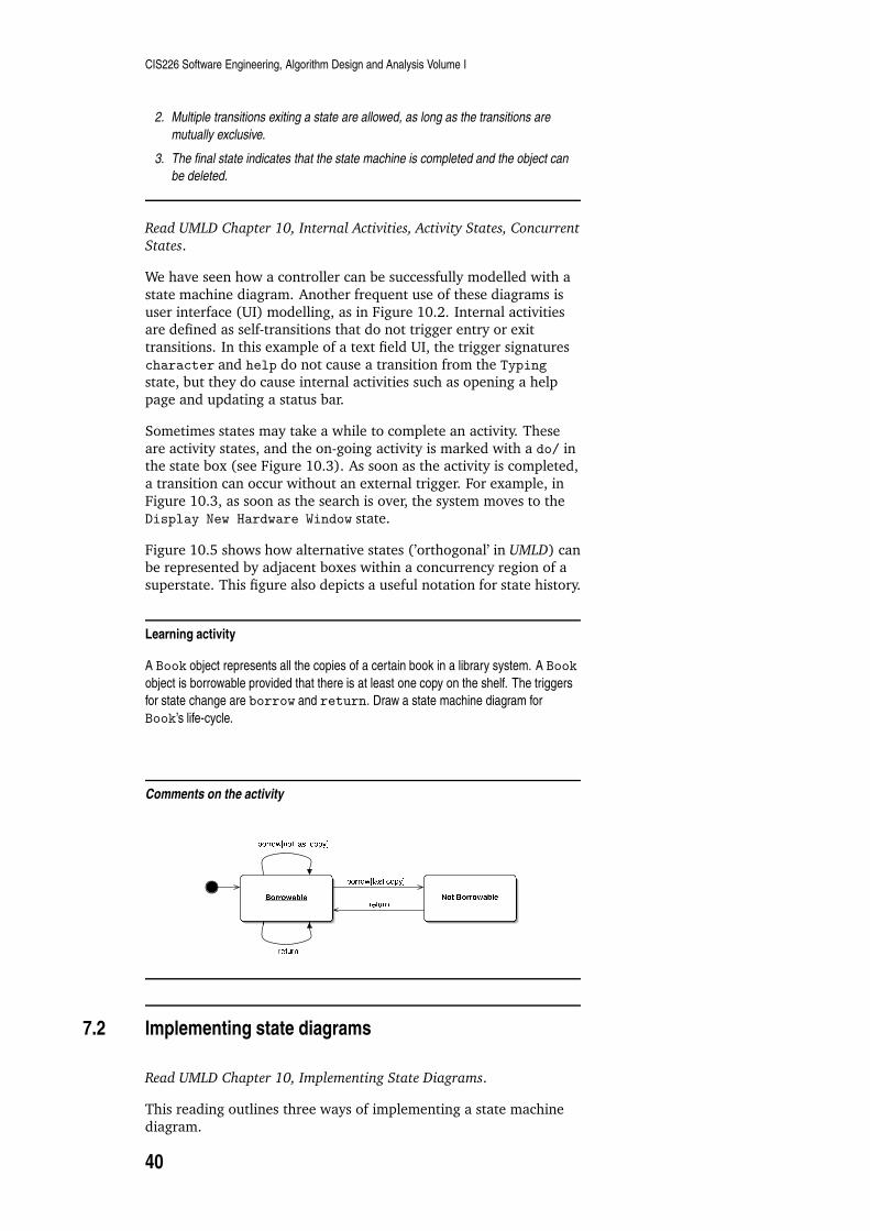
CIS226 Software Engineering, Algorithm Design and Analysis Volume I
2. Multiple transitions exiting a state are allowed, as long as the transitions are
mutually exclusive.
3. The final state indicates that the state machine is completed and the object can
be deleted.
Read UMLD Chapter 10, Internal Activities, Activity States, Concurrent
States.
We have seen how a controller can be successfully modelled with a
state machine diagram. Another frequent use of these diagrams is
user interface (UI) modelling, as in Figure 10.2. Internal activitiesare defined as self-transitions that do not trigger entry or exit
transitions. In this example of a text field UI, the trigger signatures
character and help do not cause a transition from the Typing
state, but they do cause internal activities such as opening a help
page and updating a status bar.
Sometimes states may take a while to complete an activity. These
are activity states, and the on-going activity is marked with a do/ inthe state box (see Figure 10.3). As soon as the activity is completed,
a transition can occur without an external trigger. For example, in
Figure 10.3, as soon as the search is over, the system moves to theDisplay New Hardware Window state.
Figure 10.5 shows how alternative states (’orthogonal’ in UMLD) canbe represented by adjacent boxes within a concurrency region of a
superstate. This figure also depicts a useful notation for state history.
Learning activity
A Book object represents all the copies of a certain book in a library system. A Book
object is borrowable provided that there is at least one copy on the shelf. The triggers
for state change are borrow and return. Draw a state machine diagram for
Book’s life-cycle.
Comments on the activity
N o t B o r r o w a b l eb o r r o w [ l a s t c o p y ]r e t u r nB o r r o w a b l er e t u r nb o r r o w [ n o t l a s t c o p y ]
7.2 Implementing state diagrams
Read UMLD Chapter 10, Implementing State Diagrams.
This reading outlines three ways of implementing a state machine
diagram.
40
Summary
In the nested switch technique an if - else if - else structure
provides a direct, if laborious implementation.
The state pattern method uses a hierarchy of state classes to handle
state behaviour. In other words, each state has one state subclassand the controller has methods for each event, simply forwarding
the handle requests to the respective class. This technique turns the
if - else if - else structure into a set of objects, a goodapplication of modularisation.
The state table approach uses a data table with source/target stateinformation. This table might be generated at runtime, or
pre-loaded. In either case, an interpreter can read the table, or anautomatic code generator could generate classes based on the table.
7.3 When to use state diagrams
Read UMLD chapter 10, When to Use State Diagrams.
The state machine diagram is good at describing the behaviour of a
single object across a number of use cases. This is opposite to thesequence diagram which shows how a number of objects collaborate
during a single use case. An intermediate UML model which shows
numerous objects for several use cases exists: it is the activitydiagram, and this will be the subject of the next chapter.
7.4 Exercises
1. An Event class is responsible for making an appointment in aPersonal Organiser. Once the appointment has been made, an
alarm is set, and the date and time of the appointment are
displayed. The alarm flashes if the appointment is current. Apast appointment will still exist in the calendar, unless deleted
by the user. Draw a state machine diagram for the lifetime
behaviour of Event.
2. Choose a class with interesting behaviour from the Space
Invaders project ( Sections 3.4, 4.6, 5.4, 6.8). Draw a state
machine diagram for this class.
7.5 Summary
After studying this chapter you should be able to
recognise the four features of a state machine diagram
use the three parts of a transition label, and know what is
inferred if any part is missing
know what internal activities, activity states and concurrentstates are, and how they are notated on a state machine diagram
state and explain the three ways of implementing a state
machine diagram
know when to use state machine diagrams
41

CIS226 Software Engineering, Algorithm Design and Analysis Volume I
draw state machine diagrams using any of the features
described in this chapter
42

Chapter 8
Activity Diagrams
Essential reading
UML Distilled Chapter 11
Activity diagrams are a generalisation of flowcharts, as used to
describe procedural logic, business process and work flow. Activity
diagrams differ from flowcharts, however, by the possible inclusionof parallel behaviour. In UML terms, an activity diagram can show
the behaviour of several use cases and may involve a number ofobjects.
8.1 The basic technique
Read UMLD, Chapter 11, Introduction.
Figure 11.1 of UMLD shows the diagram for the activity Receive
Order. Any activity is made from individual actions, where eachaction is represented as a box with round edges. Figure 11.1 shows
some other important features: forks, joins, decision diamonds andmerges. All theses elements are connected by flows (also called
edges). The notation for the initial and final nodes is similar to the
initial and final states of the state machine diagram.
Learning activity
1. Does the diagram tell us anything about the order of the actions in the two
sub-activities headed by Fill Order and Send Invoice?
2. The final action, Close Order, happens immediately following the completion
of either sub-activity. True or false? Explain your answer.
3. How is conditional behaviour represented on an activity diagram?
Comments on the activity
1. No. Sub-activities that originate from a single fork happen in parallel, but no
sequence of actions can be inferred from the diagram. For example, the order
might be delivered before or after the invoice is sent.
2. False. The join establishes a synchronisation between the two branches. The
order must be delivered and paid for before it can be closed.
43
CIS226 Software Engineering, Algorithm Design and Analysis Volume I
3. Conditional behaviour is represented by a decision. A decision has a single
incoming flow and several outgoing flows. The outgoing flows are labelled by
guards. Guards are mutually exclusive. The conditional behaviour is ended by a
merge diamond which has a single out flow.
Read UMLD, Chapter 11, Decomposing an Action.
Figures 11.2 and 11.3 illustrate how sub-activities from one diagram
can be factored out as actions on another. Notice the strange rake
symbol, indicating a sub-activity within an action box. Figure 11.3also shows how a method call can be added to an activity, using the
notation
Class::method.
Read UMLD, Chapter 11, Partitions.
The activity diagrams we have seen so far depict what happens, butnot which objects are involved in the actions. If you need to show
which actions are performed by a particular class, the activity
diagram can be organised into partitions, also known informally asswim lanes (see Figure 11.4).
Read UMLD, Chapter 11, Signals.
The initial mode in an activity diagram corresponds to the
invocation of a program or method. Actions can also respond to time
signals and accept signals. A signal arises from an external process.
Learning activity
1. According to Figure 11.5, when can I leave for the airport?
2. Explain how Figure 11.6 resolves the apparent paradox of two contradictory
actions, Book Itinerary and Cancel Itinerary happening in parallel
branches.
Comments on the activity
1. Within two hours of the flight, and only after the taxi has arrived.
2. The contradictory sub-activities are in a race. The activities are not joined, but
end on the final state. The slower flow is terminated upon arrival of the quicker
flow at the final state.
8.2 Advanced techniques
These advanced techniques take us some way into the vast UMLspecification of an activity diagram. The basic technique will be
adequate for most of the activity diagrams you will be drawing. You
are not expected to use all of the advanced techniques of this sectionin your activity diagrams, but you should certainly recognise them
in other diagrams and know what the technique is used for.
44

When to use activity diagrams
Read UMLD, Chapter 11, Tokens.
Tokens are a means of tracing flow through the diagram, The initialnode creates a token which is passed from action to action. Any
encountered fork creates additional tokens (one per alternativesub-activity), which are subsequently destroyed at a join.
Read UMLD, Chapter 11, Flows and Edges.
Figure 11.7 shows four ways of depicting an edge. The connectors
are purely for convenience, but the lower two diagrams of thisfigure show how to depict object transfer. The transferred objects
play the role of tokens, but they can carry data as well.
Read UMLD, Chapter 11, Pins and Transformations.
Pins are an optional annotation, useful if you want to parameteriseactions. A transformation must be shown on the diagram if the
output parameters of an outboard action do not match the inputparameters of a receiving action. This transformation can only
change one pin parameter into another. It must have no further side
effect.
Read UMLD, Chapter 11, Expansion Regions.
Expansion regions are useful for situations involving multiple
actions that have been triggered from a single action upstream. In
Figure 11.9, Choose Topics generates a list of topics which aredealt with at the same time (note the keyword concurrent). Figure
11.10 shows another way of indicating that a single action is
repeated. In this case, concurrency is assumed. Expansion regionsgenerate multiple tokens: there is a token for each article in Figures
11.9 and 11.10. Simply, there is a single written article for eachlisted topic.
Read UMLD, Chapter 11, Flow Final.
The flow final (see Figure 11.11) indicates the end of a particular
flow, but without terminating the entire activity. The decisiondiamond in this figure rejects articles, and the token is destroyed in
the flow final. The overall effect is that the number of written
articles can be less than the number of topics.
Read UMLD, Chapter 11, Join Specifications.
A join specification attaches a boolean expression to a join. The
specification is evaluated at the arrival of each token and an outputtoken is only generated when the expression is true.
8.3 When to use activity diagrams
Read UMLD, Chapter 11, When to Use Activity Diagrams.
Work flow and process modelling frequently involve parallelbehaviour and this is well represented by an activity diagram. The
diagram can show several use cases and objects and interpolates
between the state machine and sequence diagram modellingtechniques. The ability of an activity diagram to represent
procedural logic makes them useful to software architects who use
45
CIS226 Software Engineering, Algorithm Design and Analysis Volume I
UML in the programming mode.
8.4 Exercises
1. Continuing with the Personal Organiser project, draw an activity
diagram for an event which is scheduled to occur at a fixed time
over a number of weeks. The event might have an associatedemail reminder which is sent to the event attendees on the day
before the meeting, and an alarm is activated on the actual day
of the meeting. The alarm is deactivated when the meeting hasfinished. Any event might be cancelled at any time.
2. Choose a set of use cases from the Space Game project and
draw an activity diagram to show how various actionscontribute to an overall behaviour.
8.5 Summary
After studying this chapter you should be able to
recognise and understand the meaning of: initial node, actions,activity final, forks, joins, decisions, merges, flows and edges as
they appear on activity diagrams
construct activity diagrams for procedural logic
construct activity diagrams for several use cases or a welldefined activity
describe in words the content of an activity diagram
know how to decompose an activity into sub-activities
know how to include method calls in an action
partition an activity diagram
recognise the symbols for time and accept signals
use, where appropriate, the time and accept notation
understand the use of tokens
recognise the advanced techniques associated with pins,
expansions, and join specifications
know when to use activity diagrams
46

Chapter 9
Summary of UML modelling
techniques
Essential reading
UML Distilled Chapters 2, 6-8, 12-17
In the preceding chapters we have introduced five UML techniques:scenarios/use cases and class, sequence, state machine and activity
diagrams. Figure 1.2 of UMLD shows the complete family of UML
techniques. As you can see, we have covered a single structuraldiagram (the class diagram) and four behavioural models. The
remaining eight UML techniques (object, package, deployment,
composite structure, activity, communication, interaction overviewand timing diagrams) will not be studied in depth in this course but
you might wish to look at them and use them in any project you aresubsequently asked to undertake.
UMLD suggests that use cases and class, activity and state machinediagrams are useful tools for requirements analysis. Customer
communication is paramount during this phase, so any diagrams
you produce here will need to be simple and intuitive. The biggestrisk with UML techniques during requirements analysis is that the
domain expert will not understand your diagrams. That can lead to
bafflement, or to a false sense of confidence.
UMLD recommends that class, sequence, package, state machineand deployment diagrams are useful techniques during the design
phase, and the notation can be more precise and the diagrams more
refined at this stage. In an iterative process, the diagrams are usedas sketches or blueprints. Each iteration modifies the existing body
of diagrams, highlighting the inevitable changes as design becomes
more detailed. In principle, blueprinting produces very detailed andspecific diagrams and will lead directly to implementation. UML in
sketch mode is much more fluid - coding is based on, but notprescribed by, UML diagrams, and coding imperatives may well
cause the design to alter.
Once the system is built, UML can document the system although it
is no substitute for detailed documentation that is generated from
the code, as, for example, by the JavaDoc tool. UML illustrates thedetailed implementation documents, sketching out the important
parts of the system. Package, deployment and class diagrams are all
useful for the structural parts of the system, as well as sequencediagrams to show the important interactions between classes, and a
state machine diagram for any class with complex life-cycle
47

CIS226 Software Engineering, Algorithm Design and Analysis Volume I
behaviour.
48

Part III
Quality
49


Chapter 10
Product Quality
Essential reading
Using UML Chapter 19
Verification, validation and testing are product-based techniques forensuring that software is of high quality. Verification is the process
of making sure that we have built the product correctly i.e.
according to the specification. Validation is an attempt to ensurethat the software is fit for its purpose, and this is an open-ended and
difficult task, because we even need to look beyond the captured
requirements. Software testing contributes to both verification andvalidation.
Ultimately, the concern of software engineering is to ensure highquality, both of the product and of the process that led to its
creation. This is the focus of this part of the subject guide.
Learning activity
Define software quality.
Comments on the activity
This has already been defined in our course - see section 1.1
10.1 Verifying software
Read UUML, Chapter 19, Verification.
Verification is a check that the product and the specification agree.
In an iterative process, verification happens at each iteration.
Learning activity
What are the three areas of concern in verification of a UML development?
51

CIS226 Software Engineering, Algorithm Design and Analysis Volume I
Comments on the activity
Verification that the use cases satisfy any other requirements specification not
contained in the use case descriptions (i.e. that the use cases are complete),
verification that the classes and their interactions can provide the use cases and
verification that the code corresponds to the class design.
Verification also consists of checking that the programme compiles
and runs without error (after all, this should be requirement of the
system!). A check can also be made that the UML diagramsgenerated by the project are consistent in the sense that there is
always at least one programme that is described by the model.
10.2 Validating software
Read UUML, Chapter 19, Validation.
Validation requires the involvement of the customer and is difficult
because the aim is to find anything that might make the system less
useful to the customer than perhaps it should be, and this is veryopen-ended indeed.
Learning activity
Why is the developer poorly placed to assess the usability of the system?
Comments on the activity
Unlike a typical user, the developer understands the system, and they will therefore find
it very hard to imagine themselves as interacting with the system as users might.
Furthermore, the engineer has considerable experience of interacting with software in
general, and so is much more confident and competent than the intended users of the
system.
10.3 Testing
Read UUML, chapter 19. Testing.
Testing has three aims: to find bugs, to convince the customer that
there are no damaging bugs, and to provide information for furtherproduct development. The first aim is the most important and has
the direct implication that a successful test is one that finds a bug.
Clearly, if the system passes a set of easy tests, little has been learnt.
Learning activity
What kinds of tests are possible?
Comments on the activity
52

Exercises
Usability testing - is the system easy to use effectively?
Unit testing - checks the software modules (OO: classes) for bugs
Integration testing - do the parts of the system collaborate correctly?
System testing - this checks that the entire system meets the requirements
specification
Acceptance testing - this is the validation of the system by the customer
Stress testing - places the system under extreme conditions to check that the
system degrades gracefully rather than failing catastrophically
Regression testing - these tests confirm that the system continues to work
correctly after any modification, and can involve reapplication of any of the above
tests
Tests can be white or black box. In a black box test, a module is
checked against the specification: none of the implementation
details are available to the tester. A white box test, in contrast, iscarried out with knowledge of the modules and code. For example,
a white box test might examine extreme loop termination
conditions. A black box test will only be concerned with the publicinterface of the module.
Any test needs to be repeatable, documented and precise. A testspecification should be written at the same time as the requirements
are gathered, and this can help analyse requirements and ensurethat they are testable.
Sometimes tests can be automated, and this alleviates some of theboredom of this dull task. Apart from the tedium, testing is time
consuming (30-50% of project time), expensive and only perilously
left until the end of the development process. In an iterative project,testing is spread throughout the project life-cycle.
10.4 Exercises
1. It might appear that a class can be tested by checking that every
method contained in the class is bug free. However this isincorrect. Why is this? How can state machine diagrams help
with class testing?
2. What is encapsulation, and why might an encapsulatedcomponent be quite hard to test? In practice, how can we test a
well encapsulated class?
3. Polymorphism also presents particular problems to the tester.
Why is this? What lesson can we learn from this analysis?
Answers
1. Apart from operations, a class may also have attributes, andthese variables may determine the effects of method calls. One
method may change the state of an object in such a way that a
different method call might fail. A better way to test a class is tocheck all the ways an object may enter and leave all possible
states, as described and defined by the state machine diagram.
53

CIS226 Software Engineering, Algorithm Design and Analysis Volume I
2. An object is encapsulated if its clients need only refer to the
public interface of the object in order to accomplish its task.This is problematic in testing because the internal state of an
encapsulated object is private and hidden. In practice, methods
can be added to the class that report on the internal state.
3. Polymorphism, for example by inheritance, means thesubstitution of one component by another. However the
substituted component might override superclass methods andproduce side effects that were not present before the
substitution took place. In general, polymorphism, although a
hallmark of OO design, increases inter-module coupling becausethe whole inheritance tree must be checked to see which
method is being overridden, or variable is being shadowed.
Therefore the moral is: only use inheritance when theadvantages outweigh the disadvantages. It is not a panacea.
10.5 Summary
After studying this chapter you should be able to
define verification, validation and testing
place verification in the context of use case driven development
explain why validation is difficult from the developer’sperspective
state the aims of testing, and the criterion for a successful test
state and discuss the kinds of testing and the meaning of
black/white box testing
understand the importance of testing in the software life-cycle,and how testing relates to waterfall and iterative processes
understand the problems associated with the testing of OO
systems.
54

Chapter 11
Process Quality
Essential reading
Using UML Chapter 20.
UML Distilled Chapter 2.
Higher quality software can be achieved by focusing on two
approaches. Product quality, as we saw in the last chapter, involvesthe verification, validation and testing of the system itself. Process
quality involves a scrutiny of the human structure that produced thesoftware system.
There are no learning activities in this short chapter. They have beencollected together and placed in the exercises section at the end of
the chapter.
11.1 Project management
Read UUML, Chapter 20, Management.
The project manager has the overall responsibility for the success ofthe project. The manager’s responsibilities are wide ranging, as the
long list of this reading shows. Clearly an important responsibility iskeeping the project on track, especially since large projects overrun,
on average, by 50% of the original estimate. Estimation is difficult
because the project schedule is usually set at the outset, even beforethe requirements are well understood. And worse still, requirements
themselves may alter during the course of the project. Estimation is
especially difficult for an iterative process because there are nomilestones that mark the end of each phase (analysis, design,
implementation, testing) because all these phases are repeatedlyrevisited.
If the development is component based - and a large project almostcertainly will be - the manager must help the developers to make
best use of available components such as code libraries, re-usable
modules from other project teams in the organisation and,importantly, re-use from within the project team.
Read UMLD, Chapter 2, Fitting Process into a Project.
Software projects differ greatly, far greater than, say, the difference
between a garden shed and a house. This means that the process ofdeveloping software depends on many things: the kind of system
under development, the technology used by the development team,
55

CIS226 Software Engineering, Algorithm Design and Analysis Volume I
the size and distribution of the team, the nature of the risks, the
consequence of failure, the working styles of the team and theculture of the organisation.
The manager can also adapt any process to suit a project, althoughthis is a difficult thing to do without experience. Organisations
suffer from the repetition of expensive mistakes. In order to reduce
this toll, and for managers to gain experience, iteration and projectretrospectives are recommended.
11.2 Project planning
Read UMLD, Chapter 2, Predictive and Adaptive Planning.
One reason for the popularity of the waterfall model is that a
manager can provide clear costings and time estimates. Theseestimates are more problematic in an iterative process, but some
planning techniques are available.
In predictive planning, an initial stage serves to provide the manager
with enough information to make long term plans for the second,hopefully predictable, stage of development. Most projects,
however, undergo requirements churn whereby the requirements
change during this second stage. Of course the requirementspecification can be frozen at the end of the first stage, but there is a
risk that the delivered system no longer meets the needs of the
customer.
There are two solutions to requirements churn: place moreresources into requirements engineering, or acknowledge the
inherent complexity of software development and choose an
adaptive strategy. In adaptive projects, change is treated as normal.The project becomes controllable, but is still unpredictable. Plans
are still made in adaptive projects, but the plans are treated as
baselines to assess the consequences of change, and are not aprediction of the future.
Read UMLD, Chapter 2, Agile Processes.
Extreme programming is the most well known Agile process. These
processes are all highly adaptive and take as fundamental theassumption that the most important criterion in a project’s success is
the quality of the people working on the project, and on how theywork together. Agile methods use short time-boxed iterations of up
to a month in duration and utilise UML in sketch mode. Agile
methods are often characterised as being lightweight which meansthat there is a minimum of documentation and control points during
the project.
11.3 Exercises
1. What is an iteration retrospective? What is a project
retrospective?
2. Compare predictive and adaptive approaches to project
planning.
56
Summary
3. What milestones can be set for an iterative project? Are there
any ways of estimating project duration for an iterative process?
Answers
1. An iteration retrospective is a meeting by the team at the end of
each iteration with the intention of working out what went welland how things can be improved. This meeting can be short,
perhaps a couple of hours. It is helpful to maintain a list:
Keep: parts of the process that worked well and should beremembered and used in the next iteration.
Problems: parts that did not work well
Try: changes to improve the process.
A project retrospective happens at the end of the project, or at amajor release, and is formal, lasting a couple of days. The
project retrospective can use the same list as the iterationretrospective, but now the lessons learned apply to the next
project, rather than the next iteration.
2. In predictive planning, an initial stage serves to provide themanager with enough information to make long term plans for
the second, hopefully predictable, stage of development. This
means that the manager can develop a contract stating howmuch the project will cost, what shall be built, and what will be
delivered. This is only possible if precise and accurate
requirements are available, and change is not expected.
In adaptive projects, requirements change is treated as normal.
The project becomes controllable, but is still unpredictable.Plans are still made in adaptive projects, but the plans are
treated as baselines to assess the consequences of change andare not a prediction of the future. An adaptive approach is
recommended in the absence of precise, accurate and static
requirements. An adaptive plan can fix a budget and a deliverytime but can not predict what functionality will be delivered
within these constraints. Only iterative processes can be
adapted in this way. Predictive planning can be used with anyprocess, although it is best suited to a waterfall or staged
delivery process.
3. Since each iteration must finish with tested code of productionquality, we might mark each iteration by delivery of a particular
functionality. This can help measure the progress of a project,but it does not help with time estimation. It has been suggested
that the use cases - which represent functionalities - are a basic
unit of process time. Of course, the time to implement aparticular use case must still be guessed.
11.4 Summary
After studying this chapter you should be able to
discuss the responsibilities of a project manager
explain why estimation of cost and project duration is difficult
discuss the management of component based developments
explain the terms iteration and project retrospectives
57

CIS226 Software Engineering, Algorithm Design and Analysis Volume I
explain predictive and adaptive planning
explain requirements churn, and its relationship to predictive
and adaptive projects
58

Part IV
Resources
59

Chapter 12
Analysis and design of a personal
0rganiser
12.1 Scenarios
Make Appointment
The user scrolls the calendar to the date of the event. The user clicks on
a time box and selects the menu option ”schedule event”. A form
appears on the screen and the user enters some event details. It’s a
meeting with a client at the office, and it is not a regular event. The
user sets the alarm and arranges for an email reminder to be sent to
the client. The user fills in an additional note ”wear suit”. The user
clicks OK, the form disappears and the calendar displays a red circle
around the date of the appointment.
Make Appointment at a past date
The user scrolls the calendar to the date of the appointment. The userclicks on a time box and selects the menu option ”schedule event”. A
warning box appears on the screen with the message ”Cannot schedule
event for a past date. The user clicks OK, the warning vanishes and the
screen returns to the calendar.
12.2 Use cases
Make Appointment
Goal Level: Level 1
Main Success Scenario:
1 User scrolls calendar to date of appointment
2 User clicks on time box and selects schedule event
3 User specifies the type of event
4 User chooses if the alarm should be set
5 User chooses a regular event or single event
6 User chooses whether or not to send an email reminder, and towhom.
7 User completes any further meeting notes
8 User clicks OK and the calendar is displayed with a red circle
around the date of the appointment
Extensions:
61

CIS226 Software Engineering, Algorithm Design and Analysis Volume I
2a User has attempted to schedule an event in the past. A warning
box is displayed and the user must click OK
12.3 Class Identification
List of nouns from the two scenarios above:
Calendar
Date
Appointment
Time
Time box
Menu
Form
Screen
Event
Meeting
Client
Office
Regular event
Alarm
Reminder
Note
Red circle
Warning box
Message
The following nouns all refer to the Organiser display: Menu, Form,Screen, Red circle, Warning box, Message, time box. These are
possibly already represented by Java classes.
Meeting, Office and Note are the details of a particular event.
Client is particular role and is a potential class.
Calendar, Date, Appointment, Time, Event, Alarm, Regular event
and Reminder are tangible, long lasting, real word objects (forexample they could exist in a conventional paper-based organiser,
post-its etc.) and are good candidate classes.
12.4 UML diagrams
62
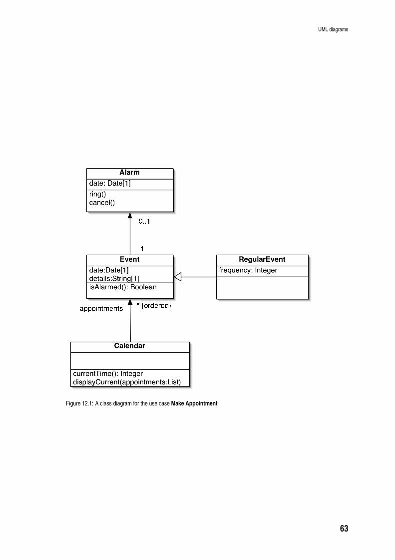
UML diagrams
E v e n td a t e : D a t e [ 1 ]d e t a i l s : S t r i n g [ 1 ]i s A l a r m e d ( ) : B o o l e a nC a l e n d a rc u r r e n t T i m e ( ) : I n t e g e rd i s p l a y C u r r e n t ( a p p o i n t m e n t s : L i s t )
* { o r d e r e d }a p p o i n t m e n t sR e g u l a r E v e n tf r e q u e n c y : I n t e g e r
A l a r md a t e : D a t e [ 1 ]r i n g ( )c a n c e l ( )10 . . 1
Figure 12.1: A class diagram for the use case Make Appointment
63
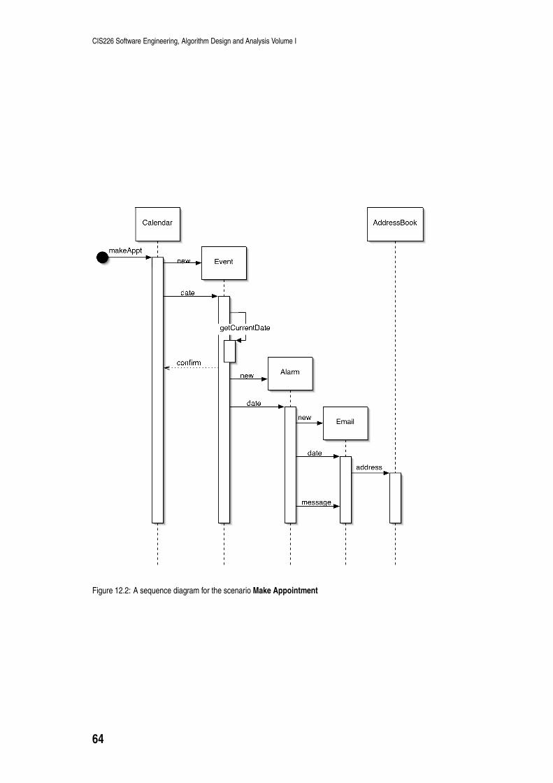
CIS226 Software Engineering, Algorithm Design and Analysis Volume I
C a l e n d a r E v e n tn e wA l a r m
d a t ec o n f i r m d a t en e w E m a i ld a t e
A d d r e s s B o o k
n e wa d d r e s sm e s s a g e
g e t C u r r e n t D a t em a k e A p p t
Figure 12.2: A sequence diagram for the scenario Make Appointment
64

UML diagrams
E v e n td a t e : D a t e [ 1 ]d e t a i l s : S t r i n g [ 1 ]f r e q u e n c y : I n t e g e ri s A l a r m e d ( ) : B o o l e a nC a l e n d a ra p p o i n t m e n t s : L i s t [ 1 ]c u r r e n t T i m e ( ) : I n t e g e rd i s p l a y C u r r e n t ( a p p o i n t m e n t s : L i s t )
* { o r d e r e d } M e e t i n gn a m e : S t r i n g
A l a r md a t e : D a t e [ 1 ]r i n g ( )c a n c e l ( )1
0 . . 1R e m i n d e rm e s s a g e : S t r i n g
A p p o i n t m e n ta t t e n d e e s : L i s tE m a i la d d r e s s : S t r i n gm e s s a g e : S t r i n gs e n d D a t e : D a t e
1 *
A r e g u l a r e v e n t h a sf r e q u e n c y > 1 .Figure 12.3: A refined class diagram for the use case Make Appointment
65
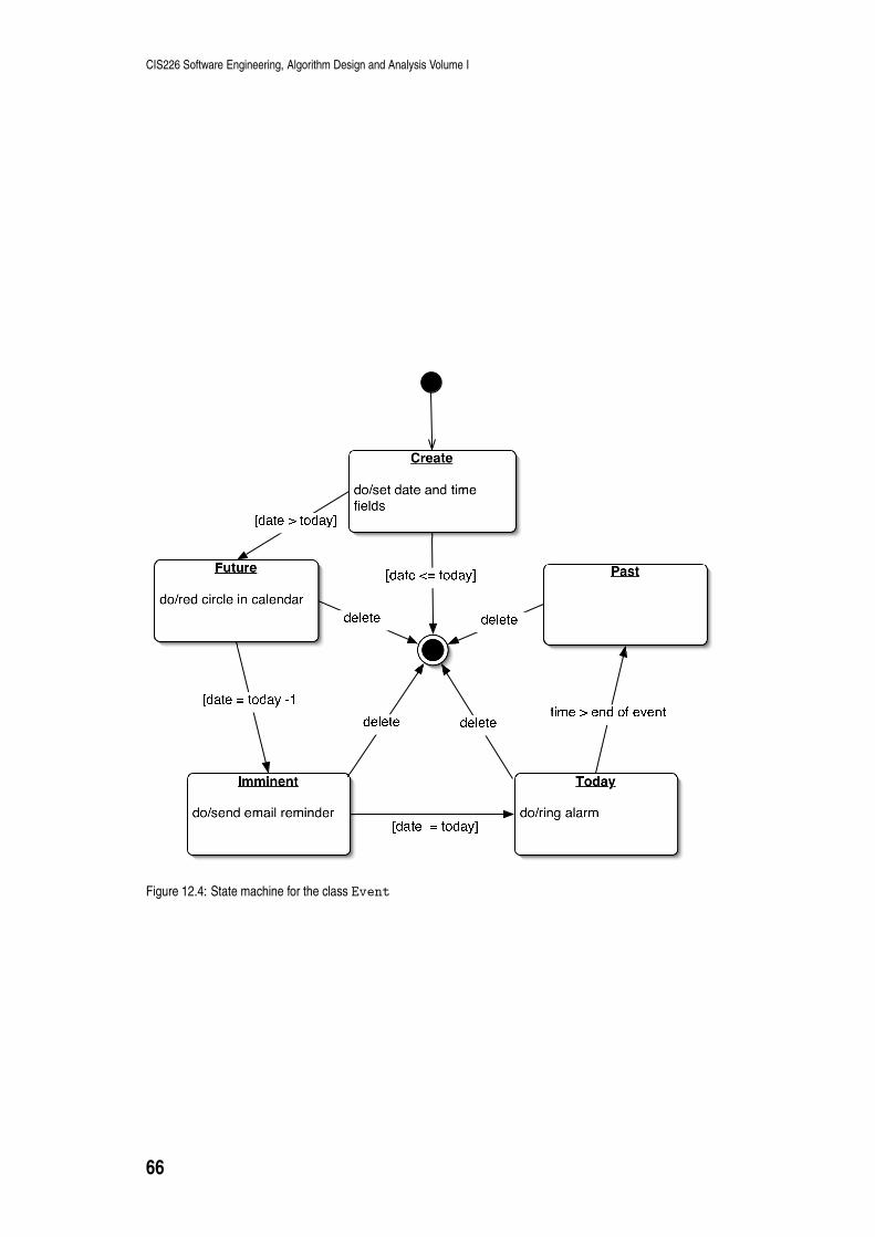
CIS226 Software Engineering, Algorithm Design and Analysis Volume I
C r e a t ed o / s e t d a t e a n d t i m ef i e l d s
I m m i n e n td o / s e n d e m a i l r e m i n d e r
F u t u r ed o / r e d c i r c l e i n c a l e n d a r[ d a t e > t o d a y ] [ d a t e < = t o d a y ]
[ d a t e = t o d a y ÿ 1[ d a t e = t o d a y ] T o d a yd o / r i n g a l a r m
P a s tt i m e > e n d o f e v e n t
d e l e t ed e l e t ed e l e t e d e l e t e
Figure 12.4: State machine for the class Event
66

UML diagrams
A c t i v a t eA l a r mS e n dE m a i l[ r e m i n d ]4 8 h o u r sb e f o r ee v e n ts c h e d u l e dd a t e s
t i m e o f e v e n t2 4 h o u r sb e f o r ee v e n t
C a n c e l
l a s td a t eD e a c t i v a t eA l a r m
Figure 12.5: Activity diagram for event alarm
67

CIS226 Software Engineering, Algorithm Design and Analysis Volume I
68
Chapter 13
Sample examination paper
13.1 Advice
You will be asked to demonstrate your knowledge of the principlesof software engineering (Part I), product and process quality (Part
III) and UML notation (Part II). Additionally, you will be tested on
your ability to develop software architectures by drawing UMLdiagrams for a simple design problem (any of the diagrams from
Part II). You should know how each UML modelling technique is
placed within the whole development process (summary sections ofChapters 3 - 8 and Chapter 9). It is important, too, that you
understand, and can use, the non-diagrammatic aspects of part II:requirements capture by use case and scenario development
(Chapter 3) and class identification (Chapter 4).
A good revision strategy would be to confirm that you can do all of
the things listed in the summary sections that close each chapter.
The exercises and learning activities which are part of each chapterprovide valuable revision material and examples of questions at
examination level. It is strongly recommended that you re-visit
either the Personal Organiser or the Space Game project andpractise developing these diagrams from scratch.
You should not assume that just because there are three parts of the
guide, and that there are three questions in the examination, that
each question will test your knowledge and understanding from justone part. The exam will test how well you have integrated all
aspects of this course and you should accordingly revise all the
material presented on this guide. However you need only answertwo questions to obtain full marks, so take some time at the start of
the exam to decide which two questions you can answer best.
Good luck!
13.2 Questions
Duration: 1 1
2hours
Full marks will be awarded for complete answers to a total of two
questions. Each question carries 25 marks. The marks for each partof a question are indicated at the end of the part in [] brackets.
There are 50 marks available on this paper.
Electronic calculators are not allowed.
1. NailIt is a proposed on-line hardware store. Calculate price
69

CIS226 Software Engineering, Algorithm Design and Analysis Volume I
of order is a scenario that has been written during the
requirements capture phase of the project. Read this scenariocarefully and answer the following questions.
Calculate price of order
A customer has placed an order with an on-line hardware store.
The order consists of three order-lines: 9 boxes of nails, 144wood screws and a packet of washers. The price of the order is
calculated by looking up the unit price of each line-item (box of
nails, wood screw, packet of washers), and multiplying this priceby the number of items in the order, and then summing over all
order-lines. The system then calculates a possible discount,
determined by some rules that relate to the customer and theorder.
(a) Use this scenario to make a list of possible classes. [3marks]
(b) Prepare a candidate class list by considering each class in
turn from the list of part (a). Explain your reasons forchoosing/eliminating each possibility. [5 marks]
(c) Explain the meaning of an association class in a UML class
diagram. [5 marks]
(d) Draw a class diagram for the classes that are involved in thescenario Calculate price of order. [12 marks]
2. (a) What are the aims of testing? [3 marks]
(b) What is the criterion for a successful test? [1 mark]
(c) What is black box testing? [2 marks]
(d) What is white box testing? [2 marks]
(e) Explain the three modes of use of UML. [8 marks]
(f) Figure 13.1 shows a UML diagram. What is the name of this
type of diagram? Arrows A, B, C and D refer to elements ofthis diagram. Name these elements and explain their role in
the diagram. [9 marks]
CBA
DFigure 13.1:
3. (a) It is frequently said that the problem of software complexity
can be tackled by modularisation. Modules should have highcohesion and low coupling and present a simple interface.
Explain the meaning of these italicized words. [6 marks]
70

Answers
(b) Customers at NailIt, a proposed on-line hardware store, are
represented by instantiations of a Customer class. Write aninterface for a customer class. Your interface should include
at least four attributes and operations (only two of which
may be data accessors). [8 marks]
(c) The NailIt project manager has broken the 1 year projectdown into four activities: requirements analysis (2 months),
design (4 months), coding (3 months), testing (3 months).
Which software development process is being suggested bythis plan? Explain your answer. [3 marks]
(d) Which software process would you recommend to the NailIt
manager? Explain how the four project activities would fit
into your process, giving timescales where appropriate. [8marks]
13.3 Answers
1. (a) Customer, order, store, order-line, box, nail, screw, packet,
washers, price, unit price, line item, discount, rules.
(b) Customer: Yes - a customer class would have data andbehaviours such as calculate discount
Order: Yes - corresponds to an order in real life
On-line hardware store: No - this is the whole system
Order-line: Yes - an order is made up from various
order-lines
Box, nail, screw, packet, of washer: No - too specific, relates
to a particular order-line
Price: No - a Price class would not have any interesting
behaviour in itself. Can probably be included as a data field
in another class
Line-item: Yes, an actual thing (box of nails, screws, packet
of washers)
Unit price: No, this is an attribute of an item, not
sufficiently rich in behaviour for a class
Discount: No - a method could use the rules to calculate this
Rules: Yes/no - could be hard-wired into the customer class,
but might also be an association class for Customer-Order
(c) An association class adds attributes and operations to
associations. [Diagram similar to Figure 5.12 in UMLD].There can only be one instance of an association class
between any two participating objects.
(d) See Figure 13.2
2. (a) The aims are: to find bugs, to convince the client that there
are no important bugs, and to provide information forfurther development.
(b) A successful test causes the module/system to fail.
(c) Black box testing is done without knowledge of theimplementation. The system/module is tested against the
specification. Only the public interface of the module isavailable to the tester.
(d) The full code is available in white box testing. For example,a loop might be scrutinised for abnormal termination
conditions.
71
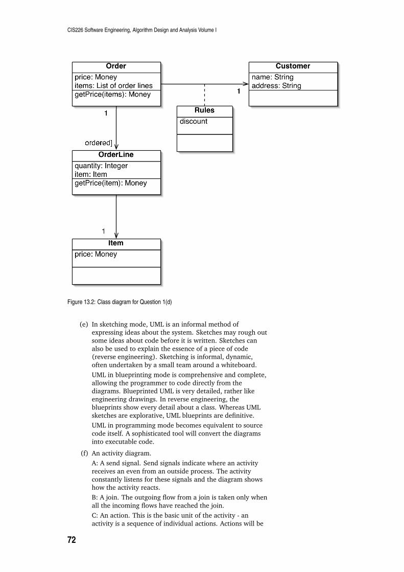
CIS226 Software Engineering, Algorithm Design and Analysis Volume IO r d e rp r i c e : M o n e yi t e m s : L i s t o f o r d e r l i n e sg e t P r i c e ( i t e m s ) : M o n e yO r d e r L i n eq u a n t i t y : I n t e g e ri t e m : I t e mg e t P r i c e ( i t e m ) : M o n e y
I t e mp r i c e : M o n e y
1★[o r d e r e d ]★1
C u s t o m e rn a m e : S t r i n ga d d r e s s : S t r i n g★ 1R u l e sd i s c o u n t
Figure 13.2: Class diagram for Question 1(d)
(e) In sketching mode, UML is an informal method ofexpressing ideas about the system. Sketches may rough out
some ideas about code before it is written. Sketches can
also be used to explain the essence of a piece of code(reverse engineering). Sketching is informal, dynamic,
often undertaken by a small team around a whiteboard.
UML in blueprinting mode is comprehensive and complete,
allowing the programmer to code directly from thediagrams. Blueprinted UML is very detailed, rather like
engineering drawings. In reverse engineering, the
blueprints show every detail about a class. Whereas UMLsketches are explorative, UML blueprints are definitive.
UML in programming mode becomes equivalent to source
code itself. A sophisticated tool will convert the diagrams
into executable code.
(f) An activity diagram.
A: A send signal. Send signals indicate where an activity
receives an even from an outside process. The activity
constantly listens for these signals and the diagram showshow the activity reacts.
B: A join. The outgoing flow from a join is taken only when
all the incoming flows have reached the join.
C: An action. This is the basic unit of the activity - an
activity is a sequence of individual actions. Actions will be
72

Answers
implemented either as sub-activities or as methods on
classes.
D: This is a rake symbol. It indicates that the action stands
for an entire sub-activity.
3. (a) Modularisation is the division of software into smallerprogramming elements. Java provides a hierarchy of
modules: methods, classes, packages.
A Cohesive module performs a single task and requires little
interaction with other modules to accomplish this. Forexample, a method should do only one thing or alter a
single value, with no other side effects.
Coupling refers to the connectivity between modules.
Ideally this should be at a minimum and this is not alwaysin object systems where there is no check to the number of
modules that can be inter-related.
(b)-name: String
-address: String
-cardNumber: Integer
-isRegularCustomer: Boolean
+getName(): String
+setName(name: String): void
+calculateDiscount(): Float
+getCreditRating(): Float
(c) This is a waterfall style because each activity occurs once
and there is no (or, only exceptionally) back flow toprevious activities.
(d) An iterative style is far better. The project is broken down
into subsets of functionality. A single iteration negotiatesthe complete software cycle: analysis, design, coding and
testing. Four 3 month iterations might be planned, each one
delivering one quarter of the functionality. This is calledtime boxing. The system should be of prediction quality at
the end of each iteration. If it is not possible to build all ofthe functionality during a particular time box, then some of
the planned functionality must be dropped. Unlike the
waterfall style, iterative approaches allow for code reworkand deletion, so that poorly designed code can be replaced
rather than patched.
73