circulation design standards
TRANSCRIPT
Circulation Design Standards
9.1 INTRODUCTION
9.1.1 The image of the installation is greatly determined by the design and location of roadways, walkways, entrances, and parking lots. The primary roadway system and parking lots utilize considerable amounts of land and are a visually dominant element of any installation. The location of primary circulation elements is presented in Section 7, Site Planning. This section discusses the details of circulation design and impacts.
9.1.2 The circulation system provides a primary vantage point from which all installations are viewed. Safe and efficient vehicular movement results in better orientation and contributes to the development of a positive environment for installation personnel and visitors. The circulation component is used to assess the circulation elements of the installation and identify specific characteristics that provide visual zone and theme identity.
9.1.3 Roadways, pedestrian walkways, and bicycle trails will be designed to provide a hierarchy of circulation design and carrying capacity. Functionally, a hierarchical network can be created that separates incompatible types of traffic. This
Fort Bliss Installation Design Guide 8-9-1

Circulation Design Standards
Fort Bliss Installation Design Guide
separation of traffic promotes sustainability because it results in more efficient energy consumption.
9.1.4 Visually, the circulation hierarchy can be reinforced through design, planting, signage, and lighting to promote a more attractive visual experience and promote a sense of orientation.
9.2 CIRCULATION OBJECTIVES
The goal for the circulation system on the installation is to establish a sustainable system that promotes aesthetic appeal, environmental preservation, and energy conservation while providing safe and efficient circulation. The objectives below should be followed to achieve a sustainable circulation system:
Figure 9.2.1 - Vehicular/pedestrian system.
• Provide circulation that meets antiterrorism and security requirements while promoting and enhancing public health and safety.
Figure 9.2.2 - Separate pedestrian/ bicycle/ vehicular
access • Provide a system of circulation that includes all forms of
vehicular and pedestrian circulation (Fig. 9.2.1).
• Provide a system that includes hierarchies of vehicular and pedestrian traffic flow (Fig. 9.2.2).
• Adapt the circulation system to the natural conditions of the site (Fig. 9.2.3).
• Improve the existing circulation network for expansion, safety, way finding and appearance. Figure 9.2.3 - Adapt circulation
to topography.
• Promote maintenance and repair of existing and proposed circulation systems.
9.3 ROADWAY HIERARCHY
9.3.1 The roadway network of the installation should functionally and visually reflect a logical hierarchy of traffic circulation. The network should separate types of traffic by function and volume, ranging from through traffic to local traffic. The visual character of each segment of the network should appropriately convey its role and function within the overall network. The basic network is classified as follows in terms of the type, character, and appearance of the road (Fig. 9.3.1).
Figure 9.3.1 - Roadway hierarchy
8-9-2

Circulation Design Standards
9.3.1.1 Highways. Highways provide primary high-speed traffic access to, around, or through a military installation. The design includes:
9.3.1.1.1 Continuous, relatively straight or large radii curvilinear alignments that carry high-speed through-traffic movement between major activity centers within a region.
9.3.1.1.2 A minimum of two lanes in each direction typically divided by a median or median divider.
9.3.1.1.3 Alignments that border lane use areas rather than bisect them, and green space buffers between the road and adjacent uses.
9.3.1.1.4 Controlled access onto the road.
9.3.1.1.5 Either grade-separated or at-grade channelized intersections with traffic signal controls.
9.3.1.1.6 Shoulders for emergency stopping but strict prohibition of on-street parking.
9.3.1.1.7 Street signing, lighting, and planting that reflect the high-speed nature of traffic movement.
9.3.1.2 Primary Roadways. These are arterial routes that connect major activity centers, provide the primary access through the installation, and provide the means by which most people view the installation. These roadways often traverse the entire installation and carry the heaviest volume of traffic, resulting in high speed and high visibility corridors. Direct access to this type of road should be restricted to crossing at major intersections. Primary roadways (Fig. 9.3.1.2a) are designated as boulevards (Fig. 9.3.1.2b) in urban areas and as avenues in rural and suburban areas. Design characteristics include:
Figure 9.3.1.2a - Primary roadway
9.3.1.2.1 Continuous, through-traffic alignments that are relatively straight or large-radii curvilinear to handle moderate to heavy traffic.
9.3.1.2.2 Alignments that form the boundary between different land uses are preferable to alignments that transect a land use zone. Figure 9.3.1.2b – Boulevard
9.3.1.2.3 Two or more moving lanes in each direction typically divided by a median.
Fort Bliss Installation Design Guide 8-9-3

Circulation Design Standards
9.3.1.2.4 Controlled access and a minimum of curb cuts limited to entranceways to major facilities or building groups.
9.3.1.2.5 At-grade intersections with signal controls.
9.3.1.2.6 On-street parking prohibited.
9.3.1.2.7 Medians, street lighting, signing, and planting that enforce the moderate- to high-speed nature and importance of the road.
9.3.1.2.8 Curbs, gutters, and sidewalks provided in all cantonment areas and other residential areas with densities greater than two dwelling units per acre.
9.3.1.3 Secondary Roadways. Secondary roadways serve as connectors between primary roads and tertiary roads and typically connect primary roads to adjacent land use zones (Fig. 9.3.1.3a and 9.3.1.3b). Secondary roads accommodate moderate to slow traffic speeds with one moving lane in each direction. On-street parking should be prohibited and left-turn lanes provided at intersections with primary roads. Design characteristics include:
9.3.1.3.1 Continuous through-traffic alignment between primary roads, either straight or curvilinear based upon the design speed topography and land pattern.
Figure 9.3.1.3a - Secondary street
9.3.1.3.2 Direct access to abutting property.
9.3.1.3.3 A maximum of two moving traffic lanes in each direction, either undivided or a boulevard with planted median.
9.3.1.3.4 On-street parking generally prohibited.
9.3.1.3.5 Sidewalk separated from the road by a planting strip. Figure 9.3.1.3b - Improved,
visually appealing streetscape
9.3.1.3.6 Street lighting, signing, and planting that reflects the moderate-to-slow speed nature of traffic and the character of the land use area they are in.
9.3.1.3.7 Curbs, gutters, and sidewalks provided in all cantonment area and other residential areas with densities greater than two dwelling units per acres.
9.3.1.4 Tertiary Roadways. Tertiary roadways provide access to individual facilities, parking and service areas. They
8-9-4 Fort Bliss Installation Design Guide

Circulation Design Standards
are designed to handle low speed, low volumes of traffic, with one lane in each direction. Tertiary roadways make use of “T” intersections and cul-de-sacs to reduce through traffic, promote safety, and limit noise impacts from truck traffic (Fig. 9.3.1.4a and Fig. 9.3.1.4b). Design characteristics include:
9.3.1.4.1 Alignments designed to discourage through-traffic.
9.3.1.4.2 Alignments relatively short and straight or curvilinear keeping with topography, land use, and slow speed.
9.3.1.4.3 Generally a maximum of two moving traffic lanes, one in each direction. Figure 9.3.1.4a - Tertiary
street elevation 9.3.1.4.4 On-street parking allowable on an infrequent overflow basis by the addition of a parallel parking lane or bay.
9.3.1.4.5 Curbs, gutters, and sidewalks provided in all cantonment areas and other residential areas with densities greater than two dwelling units per acres.
9.3.1.4.6 Sidewalks may be limited to one side only, depending upon need.
9.3.1.4.7 Street lighting, signing, and planting in character with slow traffic speed and land use area within which the road is located.
Figure 9.3.1.4b - Tertiary street plan
9.3.1.5 Cul-de-sacs. Cul-de-sacs are short dead-end tertiary streets located primarily in residential areas (Fig. 9.3.1.5). They connect at one end to a tertiary or secondary street and have a turnaround at the other end, providing direct access to an abutting property while preventing through traffic. Design characters include:
9.3.1.5.1 Short, straight, or curvilinear alignment to serve abutting property.
Figure 9.3.1.5 - Cul-de-sac plan9.3.1.5.2 Generally a maximum of two traffic lanes, one in each direction.
9.3.1.5.3 Generally a maximum length of 600 feet, or less, except in areas where terrain and low density justify a longer length.
9.3.1.5.4 Turnarounds must include a diameter to accommodate fire and garbage trucks.
Fort Bliss Installation Design Guide 8-9-5

Circulation Design Standards
Fort Bliss Installation Design Guide
9.3.1.5.5 Turnarounds can be either symmetrical or offset.
9.3.1.5.6 Turnarounds should have center planting islands to reduce the expanse of paved area (Fig. 9.3.1.5.6).
9.3.1.5.7 Overflow parking can be provided on street in parking bays or within center of turnarounds.
9.3.1.5.8 Sidewalks, if any, are generally limited to one side of the road.
Figure 9.3.1.5.6 - Cul-de-sac section may incorporate
plantings.
9.3.1.5.9 Street lighting, signing, and planting are in character with the slow traffic speed and the land use area being served.
9.3.1.6 Tactical vehicle trails provide alternative access for armored vehicles and other vehicles utilized in combat readiness training. They are recommended for installations with high use of armored vehicles to enhance movement of the vehicles and reduce traffic congestion on the other installation roadways. These trails provide one lane access for vehicles between motor pools and maneuver areas. It is recommended that these trails be hard surfaced within developed areas, with concrete of a thickness to withstand the weight of armored vehicles. The hard surface will reduce dust pollution. These trails should be designed to provide as direct access as possible while minimizing crossings with primary, secondary, or tertiary roads. All crossings with the other roadway systems should be paved with concrete to support the weight of the vehicles, and clearly marked with signage.
Figure 9.4 - Antiterrorism roadway setbacks within a
controlled perimeter 9.4 ROADWAY SETBACKS
Department of Defense Antiterrorism standards state that all inhabited buildings within a controlled perimeter will be setback a minimum of 10 meters (33 feet) from roadways, and that troop billeting and primary gathering spaces shall be setback a minimum of 25 meters (82 feet) from roadways. Inhabited buildings not within a controlled perimeter the minimum setback distance is 25 meters (82 feet) and for primary gathering places and troop facilities the minimum distance is 45 meters (148 feet) (Fig. 9.4). (See, Unified Facilities Criteria (UFC) 4-010-01, DoD Minimum Antiterrorism Standards for Buildings, Table B-1).
Figure 9.5.1 – Street plantings create a positive visual image at
Credit Union entrance.
8-9-6
Circulation Design Standards
9.5 ROADWAY SYSTEM DESIGN
9.5.1 The location and design of new circulation system alignments as well as improvements to the existing system should be prepared to promote development sustainability. They should be designed to minimize impacts, relieve driver monotony, and provide a positive visual experience for the user, without compromising safety (Fig. 9.5.1). The following design techniques should be applied to circulation system design.
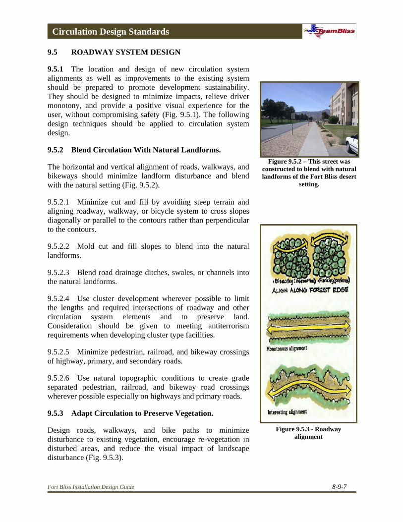
Figure 9.5.2 – This street was constructed to blend with natural landforms of the Fort Bliss desert
setting.
9.5.2 Blend Circulation With Natural Landforms.
The horizontal and vertical alignment of roads, walkways, and bikeways should minimize landform disturbance and blend with the natural setting (Fig. 9.5.2).
9.5.2.1 Minimize cut and fill by avoiding steep terrain and aligning roadway, walkway, or bicycle system to cross slopes diagonally or parallel to the contours rather than perpendicular to the contours.
9.5.2.2 Mold cut and fill slopes to blend into the natural landforms.
9.5.2.3 Blend road drainage ditches, swales, or channels into the natural landforms.
9.5.2.4 Use cluster development wherever possible to limit the lengths and required intersections of roadway and other circulation system elements and to preserve land. Consideration should be given to meeting antiterrorism requirements when developing cluster type facilities.
9.5.2.5 Minimize pedestrian, railroad, and bikeway crossings of highway, primary, and secondary roads.
9.5.2.6 Use natural topographic conditions to create grade separated pedestrian, railroad, and bikeway road crossings wherever possible especially on highways and primary roads.
9.5.3 Adapt Circulation to Preserve Vegetation.
Figure 9.5.3 - Roadway alignment
Design roads, walkways, and bike paths to minimize disturbance to existing vegetation, encourage re-vegetation in disturbed areas, and reduce the visual impact of landscape disturbance (Fig. 9.5.3).
Fort Bliss Installation Design Guide 8-9-7

Circulation Design Standards
9.5.3.1 Align roads through open areas rather than forested areas.
9.5.3.2 Minimize cut and fill to reduce the limits of clearing.
9.5.3.3 Clear only for sight distances rather than uniform right-of-way clearing.
9.5.3.4 Utilize tree wells or retaining walls to preserve specimen trees or significant vegetation areas.
9.5.3.5 Provide optimum conditions for re-vegetation by following proper planting and maintenance techniques.
9.5.3.6 Restore vegetation to disturbed areas using naturalistic plantings of native or locally adapted plant material.
9.5.4 Minimize Adverse Impacts on Adjacent Land Uses
9.5.4.1 Air Pollution. Locate roadway alignments to minimize the impact of traffic-emitted pollutants on adjacent development (Fig. 9.5.4.1). This can be accomplished by the following:
9.5.4.1.1 Locate roads adjacent to land uses that are minimally affected by traffic-emitted air pollutants.
Figure 9.5.4.1 – Landscape and berms buffer air and
noise pollution.
9.5.4.1.2 Reduce the impact of traffic-emitted pollutants on more sensitive land use areas by locating the roadways downwind and/or providing planted buffers. Tactical vehicle trails should be hard surfaced to reduce dust pollution.
9.5.4.2 Noise Pollution. Design and locate roadways to reduce the impact of traffic noise on adjacent development.
9.5.4.2.1 Roads should be physically separated from sensitive land uses including residential, medical, education, recreation, administration, religious, library, community, or child care facilities.
9.5.4.2.2 Utilizing noise abatement techniques such as berms, sound barrier walls, and plant material to reduce noise levels.
9.5.4.2.3 Reroute truck and tank traffic to roadways adjacent to less noise sensitive land uses. Tracked vehicle traffic should, ideally, be routed to a system of tank trails that are totally separate from corridors used by wheeled traffic vehicles.
8-9-8 Fort Bliss Installation Design Guide
Circulation Design Standards
9.6 INTERSECTIONS
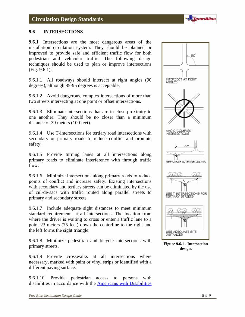
9.6.1 Intersections are the most dangerous areas of the installation circulation system. They should be planned or improved to provide safe and efficient traffic flow for both pedestrian and vehicular traffic. The following design techniques should be used to plan or improve intersections (Fig. 9.6.1):
Figure 9.6.1 - Intersection design.
9.6.1.1 All roadways should intersect at right angles (90 degrees), although 85-95 degrees is acceptable.
9.6.1.2 Avoid dangerous, complex intersections of more than two streets intersecting at one point or offset intersections.
9.6.1.3 Eliminate intersections that are in close proximity to one another. They should be no closer than a minimum distance of 30 meters (100 feet).
9.6.1.4 Use T-intersections for tertiary road intersections with secondary or primary roads to reduce conflict and promote safety.
9.6.1.5 Provide turning lanes at all intersections along primary roads to eliminate interference with through traffic flow.
9.6.1.6 Minimize intersections along primary roads to reduce points of conflict and increase safety. Existing intersections with secondary and tertiary streets can be eliminated by the use of cul-de-sacs with traffic routed along parallel streets to primary and secondary streets.
9.6.1.7 Include adequate sight distances to meet minimum standard requirements at all intersections. The location from where the driver is waiting to cross or enter a traffic lane to a point 23 meters (75 feet) down the centerline to the right and the left forms the sight triangle.
9.6.1.8 Minimize pedestrian and bicycle intersections with primary streets.
9.6.1.9 Provide crosswalks at all intersections where necessary, marked with paint or vinyl strips or identified with a different paving surface.
9.6.1.10 Provide pedestrian access to persons with disabilities in accordance with the Americans with Disabilities
Fort Bliss Installation Design Guide 8-9-9

Circulation Design Standards
Act Accessibility Guidelines (ADAAG) and the Uniform Federal Accessibility Standards (UFAS). In the event of a conflict the most stringent standards will be applied.
9.6.1.11 Create local service drives or access roads to parallel highways and primary roads to provide access to properties fronting the primary road avoiding a direct curb cut from the primary road to each individual property.
9.6.1.12 Intersections between railroad track and high-speed roads must be signaled, well marked and have a smooth transition. All other road crossings must be well marked and have clear line of sight down the tracks.
Figure 9.8.1.1a - Accessible parking space
9.7 ENTRANCE GATES
9.7.1 The location and design of the installation entrance gates is a primary component of the installation circulation system. Entrance gates must be designed to be functional, while providing security protection not only for the installation itself, but also for personnel and others waiting to be admitted to the installation. Gates should also be designed as a visual amenity to provide an aesthetically pleasing entrance to and exit from the installation. See Section 12, Force Protection, para 12.7 for information on the design standards for installation gates.
Figure 9.8.1.1b - Required minimum number of accessible
parking spaces 9.8 PARKING REQUIREMENTS
9.8.1 The total quantity of parking in any one location will vary with the needs of the facility. The following are general guidelines regarding parking requirements.
9.8.1.1 All parking lots will be accessible to persons with disabilities in accordance with the requirements of the UFAS, paragraph 4.1.1(5)(a) (Fig. 9.8.1.1a). If parking spaces are provided for employees or visitors, or both, then accessible spaces shall be provided in conformance with the required minimum number of accessible spaces shown in Figure 9.8.1.1b.
9.8.1.2 For initial planning and programming, allocate 400 square feet of parking lot area per car. The total provides adequate minimum space for the parking spaces, access drives, and planting islands that make up a parking lot. This allocation is not withstanding tactical military vehicles.
8-9-10 Fort Bliss Installation Design Guide
Circulation Design Standards
9.8.1.3 Minimize parking space requirements of a facility by selecting a site that will allow the sharing of parking with related activities.
9.8.1.4 Small parking lots are usually preferable to large lots because they enhance the visual environment by increasing the percent of landscaped area to paved area and allow more conformance to natural topography.
9.8.1.5 The monotony of large parking areas can be altered by the use of designs such as curvilinear parking or the introduction of large planting islands.
9.8.1.6 Promote means of access other than vehicular by providing alternative means of access such as walkways and bikeways.
9.9 PARKING LOT LOCATION AND DESIGN
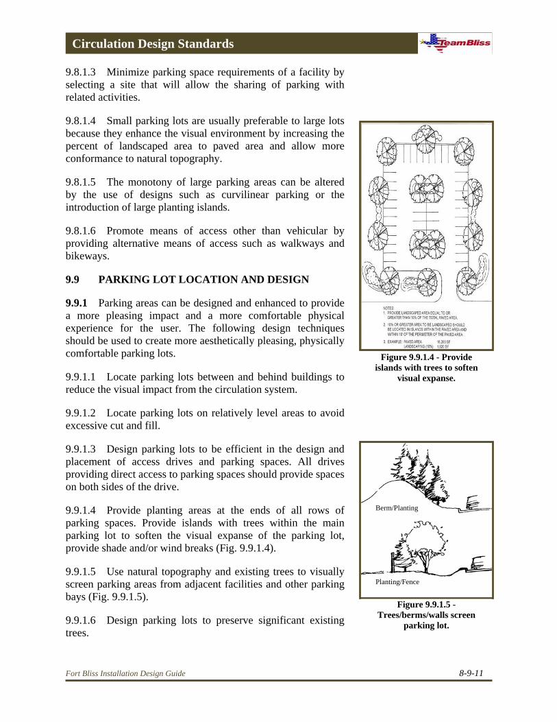
9.9.1 Parking areas can be designed and enhanced to provide a more pleasing impact and a more comfortable physical experience for the user. The following design techniques should be used to create more aesthetically pleasing, physically comfortable parking lots. Figure 9.9.1.4 - Provide
islands with trees to soften visual expanse. 9.9.1.1 Locate parking lots between and behind buildings to
reduce the visual impact from the circulation system.
9.9.1.2 Locate parking lots on relatively level areas to avoid excessive cut and fill.
9.9.1.3 Design parking lots to be efficient in the design and placement of access drives and parking spaces. All drives providing direct access to parking spaces should provide spaces on both sides of the drive.
Berm/Planting 9.9.1.4 Provide planting areas at the ends of all rows of parking spaces. Provide islands with trees within the main parking lot to soften the visual expanse of the parking lot, provide shade and/or wind breaks (Fig. 9.9.1.4).
9.9.1.5 Use natural topography and existing trees to visually screen parking areas from adjacent facilities and other parking bays (Fig. 9.9.1.5).
Planting/Fence
Figure 9.9.1.5 - Trees/berms/walls screen
parking lot. 9.9.1.6 Design parking lots to preserve significant existing trees.
Fort Bliss Installation Design Guide 8-9-11
Circulation Design Standards
9.9.1.7 On-street parking along primary and some secondary streets should be avoided because it reduces the vehicular carrying capacity of the street, is visually unattractive, and is unsafe.
9.9.1.8 Parking lots should be paved with concrete, asphalt, or other paving material.
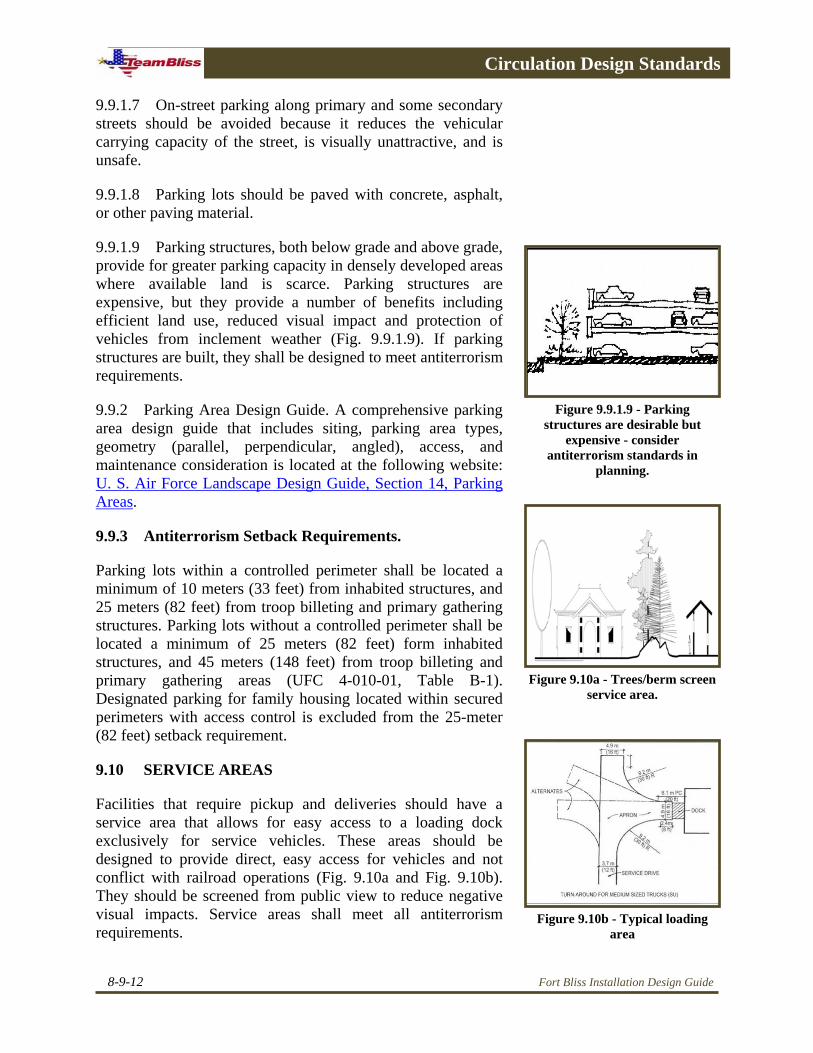
9.9.1.9 Parking structures, both below grade and above grade, provide for greater parking capacity in densely developed areas where available land is scarce. Parking structures are expensive, but they provide a number of benefits including efficient land use, reduced visual impact and protection of vehicles from inclement weather (Fig. 9.9.1.9). If parking structures are built, they shall be designed to meet antiterrorism requirements.
9.9.2 Parking Area Design Guide. A comprehensive parking area design guide that includes siting, parking area types, geometry (parallel, perpendicular, angled), access, and maintenance consideration is located at the following website: U. S. Air Force Landscape Design Guide, Section 14, Parking Areas.
Figure 9.9.1.9 - Parking structures are desirable but
expensive - consider antiterrorism standards in
planning.
9.9.3 Antiterrorism Setback Requirements.
Parking lots within a controlled perimeter shall be located a minimum of 10 meters (33 feet) from inhabited structures, and 25 meters (82 feet) from troop billeting and primary gathering structures. Parking lots without a controlled perimeter shall be located a minimum of 25 meters (82 feet) form inhabited structures, and 45 meters (148 feet) from troop billeting and primary gathering areas (UFC 4-010-01, Table B-1). Designated parking for family housing located within secured perimeters with access control is excluded from the 25-meter (82 feet) setback requirement.
Figure 9.10a - Trees/berm screen service area.
9.10 SERVICE AREAS
Facilities that require pickup and deliveries should have a service area that allows for easy access to a loading dock exclusively for service vehicles. These areas should be designed to provide direct, easy access for vehicles and not conflict with railroad operations (Fig. 9.10a and Fig. 9.10b). They should be screened from public view to reduce negative visual impacts. Service areas shall meet all antiterrorism requirements.
Figure 9.10b - Typical loading area
8-9-12 Fort Bliss Installation Design Guide

Circulation Design Standards
9.11 DROP-OFF AREAS
Facilities that include a high percentage of persons arriving by vehicle should include a vehicle drop-off area for users. Included are buildings such as headquarters, child development centers, schools, dining facilities, and clubs. Antiterrorism standards state that the access drive must be clearly defined and marked and that their intended use is clear to prevent parking of vehicles in those areas and that drop-off lanes will not be located under any inhabited portion of a building (UCF 4-010-01, para B-1.4) It is recommended that physical barriers be used to define the area. These barriers may include curbing, planters, or other barriers together with signage to identify and restrict access. The driveway shall be configured so that vehicles can be restricted during times of high alert. Access to the driveway shall be located outside the standoff area with the initial approach parallel to the building, or a barrier must be directed to prevent direct vehicular movement toward the building (Fig. 9.11).
Figure 9.11 - Typical drop off area
9.12 WALKWAYS AND PEDESTRIAN CIRCULATION
9.12.1 Walkways provide connections for pedestrians between buildings and ancillary facilities such as parking lots and other areas. Well designed and located pedestrian walkways also provide a desirable alternative to total dependence on motor driven vehicles (Fig. 9.12.1).
Figure 9.12.1 - Promote means of access other than vehicular,
provide walkways and bikeways.
9.12.2 The goal is to encourage the use of walkways as an alternative means of circulation. Pedestrian walkways should be designed and located to provide a comfortable, enjoyable experience for the user. The use of walkways within the installation promotes development sustainability by conserving energy, reducing air pollution, and decreasing the land requirement for parking. These walkways as well provide a means to increase physical fitness.
9.12.3 In order to achieve this goal the following objectives must be met:
• Provide walkways that are designed at a pedestrian scale to be comfortable and pleasant.
Figure 9.12.3 - Ramps must be provided per UFAS Standards.• Provide safe and secure pedestrian facilities that are
separate from vehicular and railroad traffic.
Fort Bliss Installation Design Guide 8-9-13
Circulation Design Standards
• Provide amenities for pedestrians.
• Provide accessibility to all users, including physically impaired or challenged persons. All street and driveway crossings shall be ramped, marked, and accessible to persons with disabilities in accordance with requirements of the UFAS (Fig. 9.12.3). See the following UFAS paragraphs for the respective standards: Curb Ramps, paragraph 4.7; Ramps, paragraph 4.8; Stairs, paragraph 4.9.
• Provide links to major attractions and generators of pedestrian traffic.
• Provide design consistency throughout the walkway and have adequate drainage.
9.12.4 Walkway Network Hierarchy. Sidewalks are classified to conform to the hierarchy roadway system - Primary walkways, secondary walkways, and tertiary walkways. Non-roadway-oriented sidewalks should be sized and placed where people will use them rather than creating worn “shortcut” paths. Railroad track crossing should be avoided, but where necessary, they should be well marked and have good line of sight. Walkways through railroad track ballast should be maintained with small, well-drained rock.
9.12.4.1 Primary Walkways.
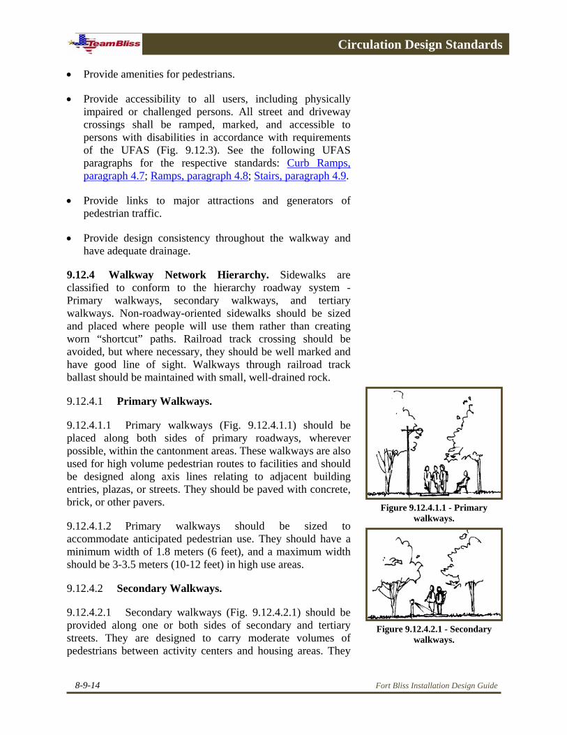
9.12.4.1.1 Primary walkways (Fig. 9.12.4.1.1) should be placed along both sides of primary roadways, wherever possible, within the cantonment areas. These walkways are also used for high volume pedestrian routes to facilities and should be designed along axis lines relating to adjacent building entries, plazas, or streets. They should be paved with concrete, brick, or other pavers. Figure 9.12.4.1.1 - Primary
walkways. 9.12.4.1.2 Primary walkways should be sized to accommodate anticipated pedestrian use. They should have a minimum width of 1.8 meters (6 feet), and a maximum width should be 3-3.5 meters (10-12 feet) in high use areas.
9.12.4.2 Secondary Walkways.
9.12.4.2.1 Secondary walkways (Fig. 9.12.4.2.1) should be provided along one or both sides of secondary and tertiary streets. They are designed to carry moderate volumes of pedestrians between activity centers and housing areas. They
Figure 9.12.4.2.1 - Secondary walkways.
8-9-14 Fort Bliss Installation Design Guide

Circulation Design Standards
should provide access to building entrances, plaza areas, or streets. They should be paved with concrete, brick, or other pavers.
9.12.4.2.2 These walkways should be sized to accommodate anticipated pedestrian use, but not less than 1.2 meters (4 feet), and a maximum of 3-3.5 meters (10 - 12 feet) in high use areas.
9.12.4.3 Tertiary Walkways. Figure 9.12.4.3.1a - Tertiary walkways
9.12.4.3.1 Tertiary walkways (Fig. 9.12.4.3.1a) provide pedestrian walkways in recreational and scenic areas for casual walking and hiking. They can be paved with concrete or bituminous asphalt or constructed with compacted red fines (chat). The layout of these walkways should have a meandering and curvilinear alignment. Paved walkways should have a minimum width of 1.2 meters (4 feet). Compacted red fines (chat) trails should have a minimum width of 1 meter (3 feet) (Fig. 9.12.4.3.1b). Where paths are designated for use by bicyclists and pedestrians, these widths should be increased an additional three feet for each bike lane.
9.12.5 Troop Running Trails.
Troop running trails should be provided for soldiers both in and out of formation. The width should 4.5-5 meters (approximately 15 feet) to provide the width necessary for four soldiers abreast with a cadence caller. Primary, secondary, and tertiary walkways can be designed to provide this function.
Figure 9.12.4.3.1b - Minimum walkway widths
9.12.6 Troop Movement Paths.
In locations where troops need to move four (4) abreast; for example, troops marching in formation between classrooms, barracks/dinning hall facilities, a hard surface walkway of adequate width should be provided.
9.12.7 Site Amenities at Walkways.
9.12.7.1 Utilize site furnishings to reinforce the walkway system hierarchy. Provide directional and informational signage, where appropriate. Locate site furnishings, such as benches, tables, waste receptacles, drinking fountains, and signage in response to travel distance and traffic volume.
Figure 9.12.8 - Place landscape and site furnishings along
walkways.
9.12.7.2 Site furnishings should be placed at regular intervals along walkways, parallel to the walk and facing the flow of pedestrian traffic.
Fort Bliss Installation Design Guide 8-9-15

Circulation Design Standards
9.12.8 Landscaping at Walkways.
Use a combination of canopy and ornamental trees along sidewalks to provide shade, define the path, provide visual interest, and discourage the creation of “shortcuts” (Fig. 9.12.8). Utilize evergreen buffer plantings to screen harsh winds and undesirable views. Discourage the use of flowering/fruit bearing trees and shrubs along walkways because of threat of insects or other problems.
9.13 BIKEWAYS
9.13.1 The use of bicycles as alternatives to the automobile has become more acceptable to installation personnel This trend is encouraged as a method of reducing the automobile vehicle trips within the installation and reduce the need for greater carrying capacity. Also, cycling is a popular recreation activity that is enhanced by the availability of a safe and well planned system of bike trails.
9.13.2 A bikeway system should provide direct routes between primary traffic and destination within the installation. This network should be continuous and minimize conflicts between bikes, pedestrians, and vehicles. Bikeways should be planned and designed according to the classifications that define the level of separation they maintain from roadways and walkways. The ideal solution for the development of bikeways is to physically separate them from both roadways and walkways.
9.13.3 Bikeways are designed according to the following classifications:
9.13.3.1 Class I Bikeway. A Class I Bikeway is intended for the exclusive use of bicycles. While it may parallel a roadway, it is physically separated by distance or a vertical barrier (Fig. 9.13.3.1). Class I Bikeway considerations include:
• A class I Bikeway provides the safest and most efficient means of bicycle travel and is the preferred option for bikeway development.
• Crossing of a Class I Bikeway by pedestrians, train, or automobile should be minimized.
• If a Class I Bikeway does not closely parallel a Figure 9.13.3.1 - Class I bikeway
8-9-16 Fort Bliss Installation Design Guide

Circulation Design Standards
roadway, it should be designed to provide appropriate bikeway gradient and curvature.
• Class I Bikeways require the greatest amount of space and advance planning to reserve land and assure appropriate routing.
• Railroad crossings should be well marked, with proper operating signals and clear sighting down the tracks. Road crossing transitions should be smooth and well drained.
9.13.3.2 Class II Bikeways. A Class II Bikeway shares the right-of-way with a roadway or walkway. It is indicated by a bikeway pictograph on the pavement and a continuous strip on the pavement or separated by a continuous or intermittent curb or other low barrier (Fig. 9.13.3.2). Class II Bikeway considerations include:
• Because some separation is provided for bicycle travel, a Class II Bikeway provides some level of safety for the bicyclist and pedestrian.
• While crossings by pedestrians or automobiles are discouraged, they are not as controllable as they are on a Class I Bikeway because the Class II Bikeway is adjacent to the walkway or roadway.
• Because Class II Bikeways are tied to the adjacent roadway or walkway, route selection is important to maintain appropriate bikeway gradient and curvature.
Figure 9.13.3.2 - Class II bikeway
• Class II Bikeways generally require less space than Class I Bikeways because they follow the alignment of and share the right-of-way with a roadway or walkway.
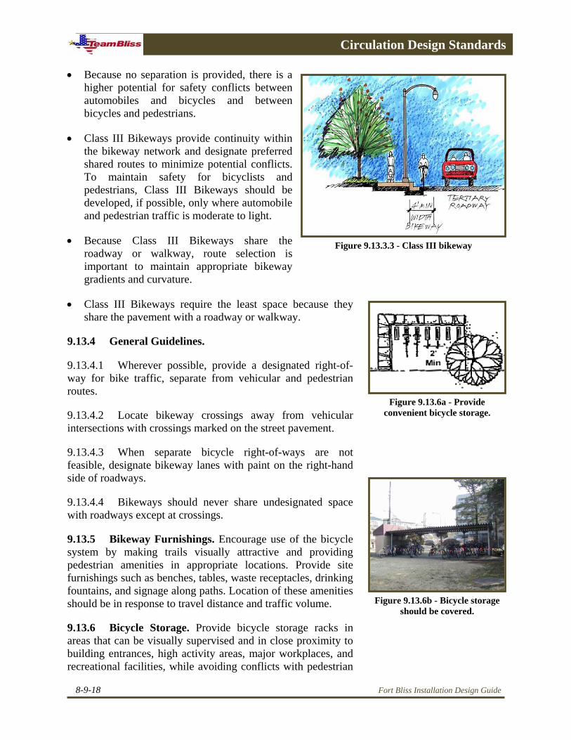
9.13.3.3 Class III Bikeways. A Class III Bikeway shares the right-of-way with a roadway or walkway. It is not indicated by a continuous strip on the pavement or separated by any type of barrier, but it is identified as a bikeway with signs (Fig. 9.13.3.3). Class III Bikeway considerations include:
Fort Bliss Installation Design Guide 8-9-17
Circulation Design Standards
Fort Bliss Installation Design Guide
• Because no separation is provided, there is a higher potential for safety conflicts between automobiles and bicycles and between bicycles and pedestrians.
• Class III Bikeways provide continuity within the bikeway network and designate preferred shared routes to minimize potential conflicts. To maintain safety for bicyclists and pedestrians, Class III Bikeways should be developed, if possible, only where automobile and pedestrian traffic is moderate to light.
• Because Class III Bikeways share the roadway or walkway, route selection is important to maintain appropriate bikeway gradients and curvature.
• Class III Bikeways require the least space because they share the pavement with a roadway or walkway.
9.13.4 General Guidelines.
9.13.4.1 Wherever possible, provide a designated right-of-way for bike traffic, separate from vehicular and pedestrian routes.
Figure 9.13.3.3 - Class III bikeway
Figure 9.13.6a - Provide convenient bicycle storage.
9.13.4.2 Locate bikeway crossings away from vehicular intersections with crossings marked on the street pavement.
9.13.4.3 When separate bicycle right-of-ways are not feasible, designate bikeway lanes with paint on the right-hand side of roadways.
9.13.4.4 Bikeways should never share undesignated space with roadways except at crossings.
9.13.5 Bikeway Furnishings. Encourage use of the bicycle system by making trails visually attractive and providing pedestrian amenities in appropriate locations. Provide site furnishings such as benches, tables, waste receptacles, drinking fountains, and signage along paths. Location of these amenities should be in response to travel distance and traffic volume. Figure 9.13.6b - Bicycle storage
should be covered.
9.13.6 Bicycle Storage. Provide bicycle storage racks in areas that can be visually supervised and in close proximity to building entrances, high activity areas, major workplaces, and recreational facilities, while avoiding conflicts with pedestrian
8-9-18

Circulation Design Standards
circulation (Fig 9.13.6a). Bicycle storage areas should be covered, especially at barracks, and easily accessible to building entrances (Fig. 9.13.6.b).
9.13.7 Landscaping. Use a combination of canopy and ornamental trees along bicycle paths for shade, route definition, and visual interest. Provide evergreen buffers to screen harsh winds and undesirable views.
9.13.8 Crosswalks. Provide crosswalks at all intersections of roads and walkways/bikeways. When laying out crosswalks, consider the following:
• Extend walk's paving across the road in heavily used areas. Raised crosswalks eliminate the need for curb ramps in sidewalks.
• Provide a clear line of sight for motorists and pedestrians. Do not plant in sight lines. Walkways should meet the road at 90 degree angles (Fig. 9.13.8).
• Adequate light should be provided.
• Provide barrier-free access at all intersections or use raised crosswalks.
9.13.9 Walkway and Bikeway Lighting Design. Roadway lights and building exterior lights can serve also as walkway and bikeway lights. Maximum use will be made of multi-purpose lighting systems. Paragraph 10.4 of Technical Manual (TM) 5-811-1, Electric Power Supply and Distribution directs the following walkway and bikeway lighting standards.
9.13.9.1 Intensities. Values are dependent upon whether walkways and bikeways are adjacent to roadways or are isolated from vehicular traffic. Figure 9.13.8 - Adequate sight
lines give pedestrians an unobstructed view of crosswalks.
9.13.9.1.1 Adjacent to Roadways. Walkways and bikeways will be illuminated to not less than one-half the maintained illumination required for adjacent roadways. Areas having in grade, such as stairs and ramps, will require special treatment. Crosswalks in the middle of the block will be illuminated to 1.5 to 2 times the normal roadway lighting level.
9.13.9.1.2 Remote from Roadways. Walkways and bikeways remote form roadways will have a minimum of 5 lux (.5 foot-candle) average illumination measured in lo-foot levels. Pedestrian tunnels will have 40 lux (4.0 foot-candles),
Fort Bliss Installation Design Guide 8-9-19

Circulation Design Standards
stairways will have 6 lux (0.6 foot-candles), and overpasses will have 3 lux (0.3 foot-candles) illumination.
9.13.9.2 Pole design. Where pole mounted lights illuminate only walkways or bikeways, shorter poles are most suitable, but luminaire height will not be less than 10 feet. Construction will be such as to minimize vandalism by use of break-resistant lenses, tamperproof screws, and sturdy poles.
9.13.10 Signs. The federal Manual of Uniform Traffic Control Devices (MUTCD) provides standards signs and markings for bicycle lanes and related bicycle facilities. See the MUTCD, Chapter 9 and any applicable amendments for traffic controls for bicycle facilities standards.
9.14 ARMY STANDARDS
9.14.1 The cited Army Standards shall be met.
• Army Regulation (AR) 420-72, Transportation Infrastructure and Dams
• Unified Facilities Criteria (UFC) 3-210-02, Design: POV Site Circulation and Parking
• Unified Facilities Criteria (UFC) 3-230-18FA, Design: General Provisions and Geometric Design for Roads, Streets, Walks, and Open Storage Areas
• Unified Facilities Criteria (UFC) 3-260-02, Design: Pavement Design for Airfields
• Technical Manual (TM) 5-811-1/Air Force AFJMAN 32-1080, Electric Power Supply and Distribution
• Technical Manual (TM) 5-850-2/Air Force AFJMAN 32-1046, Railroad Design and Rehabilitation
• Manual For Railway Engineering
• Unified Facilities Criteria (UFC) 4-010-01, DoD Minimum Antiterrorism Standards for Buildings
• Americans with Disabilities Act Accessibility Guidelines (ADAAG)
• Uniform Federal Accessibility Standards (UFAS)
8-9-20 Fort Bliss Installation Design Guide

Circulation Design Standards
• Manual of Uniform Traffic Control Devices (MUTCD)
9.15 REFERENCES
9.15.1 The following references are provided for guidance.
• U.S. Air Force, Landscape Design Guide, Parking Area
• U.S. Air Force, Landscape Design Guide, Walkways and Bikeways (Provides a comprehensive walkways and bikeways planning guide including sections on paving materials and gradients and curvature data).
• Chicago's Bike Lane Design Manual (Provides a comprehensive series of technical drawings and design specifications for bike lanes).
Go to Table of Contents
Go to Section 10Links
Fort Bliss Installation Design Guide 8-9-21

Circulation Design Standards
8-9-22 Fort Bliss Installation Design Guide