circularly polarized 2 2 mimo antenna for wlan applications · · 2018-01-13circularly polarized...
TRANSCRIPT

Progress In Electromagnetics Research C, Vol. 66, 97–107, 2016
Circularly Polarized 2 × 2 MIMO Antenna for WLAN Applications
Leeladhar Malviya, Rajib K. Panigrahi, and Machavaram V. Kartikeyan*
Abstract—A 2 × 2 circularly polarized (CP) MIMO antenna is proposed to resonate at 5.8 GHzIEEE 802.11 WLAN band for non-line of sight (NLOS) communication. The proposed design achievescircular polarization with two optimized 90◦ apart rectangular slots etched at the center of a truncatedrectangular patch. The proposed MIMO covers 5.49–6.024 GHz frequency band. The achieved isolationbetween two ports is more than 33 dB. The gain at the 5.8 GHz resonant frequency is 5.34 dBi. Thediversity performance in terms of gain, ECC, and MEG has been reported.
1. INTRODUCTION
Highly isolated or very low mutual coupling among the multiple input multiple output (MIMO) antennaelements is achieved via space isolation (diversity) and polarization isolation techniques. The first oneis not always feasible due to maximization of space requirements, which in turn requires higher cost ofmaking antennas. The second one is due to orthogonal polarization of electromagnetic waves, and ispreferred in designs. One of the issues at the receiving end is that the possibility of receiving unequalsignal gains was high, due to the polarization mismatches because of independent fading in indoor andoutdoor environments. In line of sight communication (LOS) even with linearly polarized MIMO, thereceiving antennas are able to receive unequal signal powers. The antenna that receives the least power,limits the diversity gain, which in turn lowers the signal to noise ratio (SNR). The circularly polarized(CP) MIMO eliminates the polarization mismatch effect and equally divides the power among receivingradiators. The CP antenna has focusing, anti-jamming, and anti-interference capabilities.
Basic mechanism to achieve circular polarization (CP) is discussed in detail in literature. Thefirst approach of CP wave generation was projected on the feed application at the diagonal axis of apatch. The second approach of CP wave generation depended on the perturbation of patch in terms ofeither oppositely truncated corners or oppositely located corner slots with diagonal feeding. The thirdapproach of CP wave generation was based on a 45◦ diagonal slot at the center with microstrip feed.In the fourth approach, a perturbation in a square slot with unequal L-shaped patch/ground arms [1]and asymmetric slits/slots are used to generate CP mode [2, 3].
The discussed approaches have been seen individually as well as jointly in different designs. In adesign, a dual-excitation approach with dumbbell-shaped defected ground structure (DGS) was used forreconfigurability in beam steering, and improvement in front to back-lobe ratio (FBR) [4, 5]. To avoidthe problem of narrow bandwidth a coplanar waveguide (CPW) was used for designing CP polarizedrhombic antennas for radio receivers [6]. Different fractal designs [7, 8] were used to achieve certainperformance metrices of CP antennas. Similarly, a focused antenna array with L-shaped slot helps ingenerating CP mode, when etched in an oppositely chopped inset feed patch [9]. A sequentially rotatedslot antenna structure can generate CP polarized wave for maximum power transfer [10].
Received 19 May 2016, Accepted 9 July 2016, Scheduled 21 July 2016* Corresponding author: Machavaram Venkata Kartikeyan ([email protected]).The authors are with the Electronics and Communication Engineering Department, Indian Institute of Technology (IIT), Roorkee(U. K.)-247667, India.

98 Malviya, Panigrahi, and Kartikeyan
Similarly, the surface wave controlling using shorting pins/posts [11, 12], frequency agility [13],and polarization matching are the effects of CP polarization [14]. The CP antennas are used in radiofrequency identification (RFID) trans-receive systems [15], airborne systems [16], and in automobileengineering applications [17].
The effect of CP on MIMO can be accounted as an increase of diversity gain, throughput, data rate,and capacity [18]. Similarly, to broaden the bandwidth of the CP array, multiple layers of substrateare also required along with the feed structure to make all the elements to be 90◦ phase shifted withequal amplitudes [19], and high gain can be achieved [20]. The segmented circles with 90◦ phasecoupling (polarizers or stubs) in each circle and with power divider is also a approach of MIMO CPantennas [21, 22]. A slotted array antenna with slits was also reported in literature to generate CPpolarization [23]. A polygon-shaped radiator with L-shaped arm responds with the dual-band CPcharacteristics. The isolation improvement between the MIMO radiators is achieved by the groundseparator and by the placement of radiators [24].
The proposed design achieves circular polarization by two optimized 90◦ apart rectangular slotsetched at the center of a rectangular patch. The 90◦ phased slots also enhance the bandwidth of theantenna. The two orthogonal modes with 90◦ phase and equal amplitudes are excited by slots etchedat the center of truncated rectangular patches to generate CP mode. A single microstrip feed at anappropriate location, eliminates the need of matching network, external polarizer and also reduces theoverall size of the design. A two-arm feed mechanism is used for the proposed design to spread the totalpower among radiating elements. It consists of 50 Ω, 70.7 Ω, and 100 Ω microstrip transmission linesand is helpful in designing of 2× 2 MIMO. In our design, a 2× 2 MIMO antenna with CP polarizationis proposed with more than 33 dB of isolation between radiating elements. The designed MIMO covers5.8 GHz IEEE 802.11 WLAN standard. The proposed work is reported in four sections. Section 2describes design concept and fabrication. Sections 3 and 4 explain experimental results and conclusion.
2. DESIGN STUDIES AND RESULTS
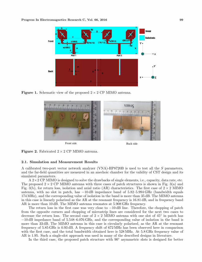
The proposed 2 × 2 MIMO antenna is designed with circular polarization to trans-receive signals withleft/right-hand CP wave. The proposed 2-port MIMO antenna with 50 Ω ports is designed usingcomputer simulation tool (CST) version 12.0 and fabricated on an FR4 dielectric substrate (thicknessof 1.524 mm, permittivity of 4.4, and loss tangent of 0.025) of size 27.69 × 97 mm2. The particle swarmoptimization (PSO) approach with min-max algorithm was set to achieve the best design goals for thedesired band of operation and for required antenna parameters. The minimum return loss, high isolation(low mutual coupling), compact size, sufficient antenna gain, and specific WLAN application are thedesign guidelines behind the selection of the proposed antenna.
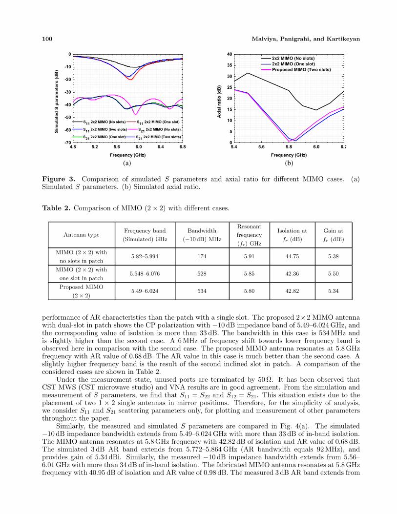
A single microstrip feed is designed for 1× 2 combinations. The microstrip feed is selected here toavoid cutting of substrate and conductive layers (as used in coaxial feed structure), and also to controlsurface waves. The proposed design achieves circular polarization by the optimization of two 90◦ apartrectangular slots etched at the center of the rectangular patch. A full ground structure is selected indesign along with a slot (width 1.5 mm) in the ground in between the power divider arms to avoiddirect coupling between them, and a ground split of 0.5 mm is used between two ports to avoid sharingof common ground. The optimized dimensions are obtained here while setting the min-max algorithmwith ±10% variation in set values. The best results were achieved after 2100 iterations and are shownin Table 1. The schematic view and fabricated MIMO antenna are shown in Fig. 1 and Fig. 2.
Table 1. Optimized values of considered parameters (mm).
Parameter a b c d e f g h l (50 Ω) w (50 Ω) l (70.7 Ω)
Value 9.64 11.0 24.98 2.96 10.5 0.692 13.75 3.26 2.0 2.96 2.0
Parameter i j k l m n o p w (70.7 Ω) l (100Ω) w (100 Ω)
Value 8.12 0.74 27.69 1.5 16.5 0.5 27.69 97.0 1.58 26.12 0.694
Progress In Electromagnetics Research C, Vol. 66, 2016 99
Front
Back
Substrate
Metal
x
Z
Y
x
Y
a
b
c
w(100 )d
e
f
R2g
hI
j
k
w(70.7 )l(50 )w(50 )
l(70.7 )
R3R1
l(100 )
Port 2Port 1
p
ml
no
Figure 1. Schematic view of the proposed 2 × 2 CP MIMO antenna.
Front side Back side
Figure 2. Fabricated 2 × 2 CP MIMO antenna.
2.1. Simulation and Measurement Results
A calibrated two-port vector network analyzer (VNA)-HP8720B is used to test all the S parameters,and the far-field quantities are measured in an anechoic chamber for the validity of CST design and itssimulated parameters.
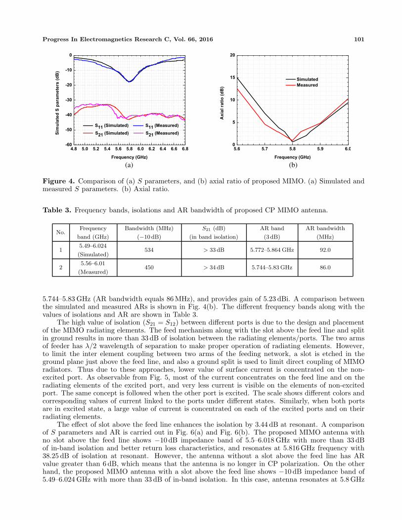
A 2×2 CP MIMO is designed to solve the drawbacks of single elements, i.e., capacity, data rate, etc.The proposed 2 × 2 CP MIMO antenna with three cases of patch structures is shown in Fig. 3(a) andFig. 3(b), for return loss, isolation and axial ratio (AR) characteristics. The first case of 2 × 2 MIMOantenna, with no slot in patch, has −10 dB impedance band of 5.82–5.994 GHz (bandwidth equals174 MHz), and the corresponding value of isolation in the band is more than 35 dB. The MIMO antennain this case is linearly polarized as the AR at the resonant frequency is 16.81 dB, and in frequency bandAR is more than 10 dB. The MIMO antenna resonates at 5.908 GHz frequency.
The return loss in the first case was very close to −10 dB line. Therefore, the chopping of patchfrom the opposite corners and chopping of microstrip lines are considered for the next two cases todecrease the return loss. The second case of 2 × 2 MIMO antenna with one slot of 45◦ in patch has−10 dB impedance band of 5.548–6.076 GHz, and the corresponding value of isolation in the band ismore than 33 dB. The MIMO antenna in this case is circularly polarized, as the AR at the resonantfrequency of 5.85 GHz is 0.93 dB. A frequency shift of 672 MHz has been observed here in comparisonwith the first case, and the total bandwidth obtained here is 528 MHz. At 5.8 GHz frequency value ofAR is 1.95. Such a single-slot approach was used in many of the described designs in literature.
In the third case, the proposed patch structure with 90◦ asymmetric slots is designed for better
100 Malviya, Panigrahi, and Kartikeyan
(a) (b)
Figure 3. Comparison of simulated S parameters and axial ratio for different MIMO cases. (a)Simulated S parameters. (b) Simulated axial ratio.
Table 2. Comparison of MIMO (2 × 2) with different cases.
Antenna typeFrequency band
(Simulated) GHz
Bandwidth
(−10 dB) MHz
Resonant
frequency
(fr) GHz
Isolation at
fr (dB)
Gain at
fr (dBi)
MIMO (2 × 2) with
no slots in patch5.82–5.994 174 5.91 44.75 5.38
MIMO (2 × 2) with
one slot in patch5.548–6.076 528 5.85 42.36 5.50
Proposed MIMO
(2 × 2)5.49–6.024 534 5.80 42.82 5.34
performance of AR characteristics than the patch with a single slot. The proposed 2×2 MIMO antennawith dual-slot in patch shows the CP polarization with −10 dB impedance band of 5.49–6.024 GHz, andthe corresponding value of isolation is more than 33 dB. The bandwidth in this case is 534 MHz andis slightly higher than the second case. A 6MHz of frequency shift towards lower frequency band isobserved here in comparison with the second case. The proposed MIMO antenna resonates at 5.8 GHzfrequency with AR value of 0.68 dB. The AR value in this case is much better than the second case. Aslightly higher frequency band is the result of the second inclined slot in patch. A comparison of theconsidered cases are shown in Table 2.
Under the measurement state, unused ports are terminated by 50 Ω. It has been observed thatCST MWS (CST microwave studio) and VNA results are in good agreement. From the simulation andmeasurement of S parameters, we find that S11 = S22 and S12 = S21. This situation exists due to theplacement of two 1 × 2 single antennas in mirror positions. Therefore, for the simplicity of analysis,we consider S11 and S21 scattering parameters only, for plotting and measurement of other parametersthroughout the paper.
Similarly, the measured and simulated S parameters are compared in Fig. 4(a). The simulated−10 dB impedance bandwidth extends from 5.49–6.024 GHz with more than 33 dB of in-band isolation.The MIMO antenna resonates at 5.8 GHz frequency with 42.82 dB of isolation and AR value of 0.68 dB.The simulated 3 dB AR band extends from 5.772–5.864 GHz (AR bandwidth equals 92 MHz), andprovides gain of 5.34 dBi. Similarly, the measured −10 dB impedance bandwidth extends from 5.56–6.01 GHz with more than 34 dB of in-band isolation. The fabricated MIMO antenna resonates at 5.8 GHzfrequency with 40.95 dB of isolation and AR value of 0.98 dB. The measured 3 dB AR band extends from
Progress In Electromagnetics Research C, Vol. 66, 2016 101
(a) (b)
Figure 4. Comparison of (a) S parameters, and (b) axial ratio of proposed MIMO. (a) Simulated andmeasured S parameters. (b) Axial ratio.
Table 3. Frequency bands, isolations and AR bandwidth of proposed CP MIMO antenna.
No.Frequency
band (GHz)
Bandwidth (MHz)
(−10 dB)
S21 (dB)
(in band isolation)
AR band
(3 dB)
AR bandwidth
(MHz)
15.49–6.024
(Simulated)534 > 33 dB 5.772–5.864 GHz 92.0
25.56–6.01
(Measured)450 > 34 dB 5.744–5.83 GHz 86.0
5.744–5.83 GHz (AR bandwidth equals 86 MHz), and provides gain of 5.23 dBi. A comparison betweenthe simulated and measured ARs is shown in Fig. 4(b). The different frequency bands along with thevalues of isolations and AR are shown in Table 3.
The high value of isolation (S21 = S12) between different ports is due to the design and placementof the MIMO radiating elements. The feed mechanism along with the slot above the feed line and splitin ground results in more than 33 dB of isolation between the radiating elements/ports. The two armsof feeder has λ/2 wavelength of separation to make proper operation of radiating elements. However,to limit the inter element coupling between two arms of the feeding network, a slot is etched in theground plane just above the feed line, and also a ground split is used to limit direct coupling of MIMOradiators. Thus due to these approaches, lower value of surface current is concentrated on the non-excited port. As observable from Fig. 5, most of the current concentrates on the feed line and on theradiating elements of the excited port, and very less current is visible on the elements of non-excitedport. The same concept is followed when the other port is excited. The scale shows different colors andcorresponding values of current linked to the ports under different states. Similarly, when both portsare in excited state, a large value of current is concentrated on each of the excited ports and on theirradiating elements.
The effect of slot above the feed line enhances the isolation by 3.44 dB at resonant. A comparisonof S parameters and AR is carried out in Fig. 6(a) and Fig. 6(b). The proposed MIMO antenna withno slot above the feed line shows −10 dB impedance band of 5.5–6.018 GHz with more than 33 dBof in-band isolation and better return loss characteristics, and resonates at 5.816 GHz frequency with38.25 dB of isolation at resonant. However, the antenna without a slot above the feed line has ARvalue greater than 6 dB, which means that the antenna is no longer in CP polarization. On the otherhand, the proposed MIMO antenna with a slot above the feed line shows −10 dB impedance band of5.49–6.024 GHz with more than 33 dB of in-band isolation. In this case, antenna resonates at 5.8 GHz

102 Malviya, Panigrahi, and Kartikeyan
Figure 5. Surface current distribution of proposed 2 × 2 MIMO antenna.
(a) (b)
Figure 6. Comparison of S parameters and axial ratio (with and without the slot above the feed line).(a) Simulated S parameters. (b) Simulated axial ratio.
frequency with 42.82 dB of isolation and AR value of 0.68 dB, 3 dB AR band of 5.772–5.864 GHz (ARbandwidth equals 92.0 MHz), and gain of 5.34 dBi. Therefore, the presence of the slot above the feedline has a positive impact on CP polarization and also on the isolation.
Similarly, the effect of the phase difference (θ01) between the major and minor slots can be seen on
AR and voltage standing wave ratio (VSWR). The considered phase difference between these asymmetricslots is 90◦. When θ0
1 is varied from 0◦ to 90◦, we observe that for 0◦ phase difference, both slots aremerged, and only a major slot is seen. In this case, the value of AR is 1.95 dB, and VSWR has a value of1.11. Similarly, when both the slots are 90◦ in phase difference, the value of AR is 0.68 dB, and VSWRhas a value of 1.12. Similarly, for 45◦ phase difference, MIMO antenna has AR value of 40 dB and VSWRof 2.57. A major difference of AR values is observable here at 5.8 GHz resonant frequency. Therefore,we may state that for 0◦ and 90◦ of phase difference between the two slots, the proposed MIMO showsCP characteristics. For the other values of θ0
1, the antenna has linear polarization. Therefore, theconsidered asymmetric slot case is better than the other cases. All the values have been plotted inFig. 7 for the validity of proposed design.

Progress In Electromagnetics Research C, Vol. 66, 2016 103
Figure 7. Effect of phase difference on proposedMIMO.
Figure 8. Gain of proposed MIMO antenna.
Antenna 2 Right polarization
Antenna 1 Left polarization
Figure 9. Left and right polarization patterns at 5.8 GHz for proposed MIMO.
2.2. Diversity Performance
The gain, envelope correlation coefficient (ECC), and mean effective gain (MEG) are used to describethe diversity behavior of the proposed 2× 2 CP MIMO antenna here. The gain is a far-field parameterand measured in an anechoic chamber using the substitution method with two standard horn antennasand with the proposed MIMO antenna. The simulated gain of the proposed 2×2 CP MIMO antenna at5.8 GHz resonant frequency is 5.34 dBi. Similarly, for the designed 2×2 CP MIMO, the measured valueof gain at 5.8 GHz resonant frequency is 5.23 dBi. The simulated and measured gain values are plottedin Fig. 8 for all the frequencies. The corresponding left polarization of antenna 1 and right polarizationof antenna 2 are shown in Fig. 9, for the effectiveness of the proposed design.
Similarly, the envelope correlation coefficient (ECC) also shows the diversity behavior of theproposed MIMO antenna. The isolation parameters S12 and S21 show only the information aboutthe coupling at the ports. However, ECC involves all the scattering parameters of the proposed MIMOto show their effects on the correlation coefficient. Lowering the value of ECC means less correlationbetween antenna elements, while higher values of it shows the negative impact. For good diversitybehavior, the value of ECC must be less than 0.5 for mobile applications. The simulated/measuredvalues of ECC [25] may be obtained using the formula shown in Equation (1). Here the values of i = 1

104 Malviya, Panigrahi, and Kartikeyan
Figure 10. ECC of proposed MIMO antenna. Figure 11. MEG of proposed MIMO antenna.
to 2 and j = 1 to 2 are for two elements, and N = 2 (as total 2 antennas).
|ρe(i, j,N)| =
∣∣∣∣∣N∑
n=1
S∗i,nSn,j
∣∣∣∣∣√√√√√∣∣∣∣∣∣
∏k(=i,j)
[1 −
N∑n=1
S∗i,nSn,k
]∣∣∣∣∣∣(1)
As observable from Fig. 10 that the simulated values of ECC lies between the range of 0–0.0005(due to very low values, it looks close to zero) in the whole frequency band, while the measured valuesof ECC between the two radiators lies in the range of 0–0.15. The simulated value of ECC at 5.8 GHzresonant frequency is 2.39 × 10⁻⁷, and the corresponding measured value of ECC is 2.6 × 10⁻². Themeasured results showed fluctuation in ECC values, though we obtained very low ECC values betweenthe two radiators at resonance and also in whole band. The big difference in the measured and simulatedranges/values is due to fabrication errors and port/cable coupling losses.
Similarly, the MEG is also a far-field parameter and is used to show diversity behavior. TheMEG [26] includes power patterns of the proposed MIMO antenna. Let the cross polarization ratiobe XPR, and the gaussian/uniform medium signals mean (μ) = 0 and variance (σ) = 20, for bothhorizontal and vertical components. These two mediums (isotropic and gaussian/uniform mediums)have been considered for the analysis of the proposed MIMO antenna, for different values of XPRusing CST simulations. Here, it has been observed that the values of MEG for isotropic medium withXPR = 0 dB show almost constant values of −3.5 dB, and with XPR = 6dB MEG lie in the range of−1.6 to −3.5 dB. Similarly, the values of MEG for Gaussian medium with XPR = 0 dB lie in the rangeof −4.3 to −6.5 dB, and with XPR = 6 dBMEG lie in the range of −2.7 to −4.9 dB. All the values ofMEGs are plotted in Fig. 11 for isotropic and gaussian mediums. A comparison of different simulatedMEG values at 5.8 GHz resonant is shown in Table 4.
Table 4. MEG comparison of proposed 2 × 2 MIMO antenna at resonant.
Frequency (GHz) MEG (Isotropic medium) MEG (Gaussian medium)XPR = 0 dB XPR = 6 dB XPR = 0dB XPR = 6 dB
5.8 −3.0 −2.25 −7.5 −6.46

Progress In Electromagnetics Research C, Vol. 66, 2016 105
Figure 12. Equivalent circuit model. Figure 13. Comparison of S parameters.
2.3. Equivalent Circuit Modeling
For the cross verification of resonant property of the proposed 2× 2 CP MIMO antenna, an equivalentcircuit model was developed using advanced system design (ADS)-2016. This in turn cross verifies theeffect of tuning behavior of each patch, slot, and discontinuities (combination of two different wavelengthtransmission lines). These are modeled as a combination of inductor (L) and capacitor (C). Each ofthe ports is replaced by a 50 Ω load. Each of the patches is modeled using series combination of L1and C1, and the effect of two asymmetric slots by the series combination of L2 and C2. Similarly,the combination of 50 Ω, 70.7 Ω, and 100 Ω microstrip transmission lines is jointly represented by seriescombination of L3 and C3, and the coupling effect between the two ports is modeled as a parallelcombination of L4 and C4. The corresponding values of these elements as L1 = 1.2 nH, L2 = 0.66 nH,L3 = 0.9 nH, L4 = 1.99 nH, C1 = 0.86 pF, C2 = 0.76 pF, C3 = 0.6 pF, C4 = 0.9 pF were simulatedusing ADS software. The equivalent model is shown in Fig. 12. The corresponding responses (S11 andS21) are compared with the CST simulated responses in Fig. 13. The responses using equivalent resonantcircuit and CST full wave simulation are very similar for the return loss and isolation parameters.
(a) (b)
Figure 14. E and H field radiation patterns of proposed CP MIMO at 5.8 GHz. (a) E field radiationpatterns. (b) H field radiation patterns.

106 Malviya, Panigrahi, and Kartikeyan
2.4. Far Field Radiation Patterns
The far-field radiation patterns of the proposed 2 × 2 CP MIMO antenna are measured in an anechoicchamber at 5.8 GHz resonant frequency for E and H field patterns, for each of the port. Theinstruments/devices required in the anechoic chamber are standard horn antenna (used as a transmittingantenna), microwave generator, power meter, and fabricated 2 × 2 CP MIMO antenna. When any oneof the port is used in receiving mode, the other port is terminated by 50 Ω to avoid any noise pick-up.
The proposed 2× 2 CP MIMO antenna elements are mirrored to have balanced radiation patternsand also to avoid mismatching. The E field radiation patterns have main lobe directions of ±10◦, andthe angular widths are 57.6◦. Similarly, the H field radiation patterns also have main lobe directionsof ±10◦, and the angular widths are 92.5◦. The measured and simulated E and H field patterns arecompared in Fig. 14(a) and Fig. 14(b).
3. CONCLUSION
A compact CP MIMO antenna with power divider was proposed for 5.8 GHz WLAN standards using twooptimized 90◦ apart rectangular slots. Various aspects of MIMO antenna were discussed in this paper forthe effectiveness of design on S parameters and axial ratio. The proposed MIMO covered 5.49–6.024 GHzfrequency band with more than 33 dB of isolation between ports and better AR characteristics. Also themeasured ECC was around 0.15, very much less than the maximum limit set for wireless communication.
REFERENCES
1. Rezaeieh, A. S., S. Simsek, and J. Pourahmadazar, “Design of a compact broadband circularlypolarized slot antenna for wireless applications,” Microwave and Optical Technology Letters, Vol. 55,No. 2, 413–418, 2013.
2. Gautam, A. K. and B. K. Kanaujia, “A novel dual-band asymmetric slit with defectedground structure microstrip antenna for circular polarization operation,” Microwave and OpticalTechnology Letters, Vol. 55, No. 6, 1198–1201, 2013.
3. Kumar, S., B. K.. Kanaujia, A. Sharma, M. Khandelwal, and A. K. Gautam, “Single feed cross slotloaded compact circularly polarized microstrip antenna for indoor WLAN applications,” Microwaveand Optical Technology Letters, Vol. 56, No. 6, 1313–1317, 2014.
4. Abraham, J., T. Mathew, and C. K. Aanandan, “A novel proximity fed gap coupled microstrippatch array for wireless applications,” Progress In Electromagnetic Research C, Vol. 61, 171–178,2016.
5. Khawaja, B. A., M. A. Tarar, T. Tauqeer, F. Amir, and M. Mustaqim, “A 1 × 2 triple bandprinted antenna array for use in next generation flying Ad-hoc networks,” Microwave and OpticalTechnology Letters, Vol. 58, No. 3, 606–610, 2016.
6. Yu, A., F. Yang, and A. Z. Elsherbeni, “A planar rhombic antenna with a broad circular polarizationbandwidth for integrated single chip radio receivers,” Microwave and Optical Technology Letters,Vol. 51, No. 6, 1493–1496, 2009.
7. Rao, P. N. and N. V. S. N. Sharma, “Compact single feed circularly polarized fractal boundarymicrostrip antenna,” Microwave and Optical Technology Letters, Vol. 52, No. 1, 141–147, 2010.
8. Bilgic, M. M. and K. Yegin, “Wideband high gain aperture coupled antenna for Ku band phasedarray systems,” Microwave and Optical Technology Letters, Vol. 55, No. 6, 1291–1295, 2013.
9. Jiang, Y., G. Wen, and H. Sun, “A new focused antenna array with circular polarization,”Microwave and Optical Technology Letters, Vol. 57, No. 12, 2936–2939, 2015.
10. Karamzadeh, S., B. S. Virdee, V. Rafii, and M. Kartal, “Circularly polarized slot antenna arraywith sequentially rotated feed network for broadband application,” International Journal of RFand Microwave Computer Aided Engineering, Vol. 25, No. 4, 358–363, 2015.
11. Al-Ajmi, A. R. and S. F. Mahmoud, “A single feed circularly polarized patch antenna for reducedsurface wave applications,” Microwave and Optical Technology Letters, Vol. 51, No. 11, 2675–2679,2009.

Progress In Electromagnetics Research C, Vol. 66, 2016 107
12. Sun, C., H. Zheng, and Y. Liu, “Analysis and design of a low cost dual-band compact circularlypolarized antenna for GPS application,” IEEE Transactions on Antennas and Propagation, Vol. 64,No. 1, 365–370, 2016.
13. Chen, H. M., K. Y. Chiu, Y. F. Lin, and S. A. Yeh, “Circularly polarized slot antenna design andanalysis using magnetic current distribution for RFID reader applications,” Microwave and OpticalTechnology Letters, Vol. 54, No. 9, 2016–2022, 2012.
14. Yang, J., C. H. Liang, and T. Wang, “Novel dual-band circularly polarized wideband antenna forWLAN and WiMAX,” Journal of Electromagnetic Waves and Applications, Vol. 26, Nos. 14–15,1881–1888, 2012.
15. Lai, X.-Z., Z.-M. Xie, and X.-L. Cen, “Design of a dual circularly polarized antenna with highisolation for RFID applications,” Progress In Electromagnetics Research, Vol. 139, 25–39, 2013.
16. Huang, W., L. Sun, B. Sun, and Q. Sun, “Circularly polarized magnetic dipole with shallow andembedded structure for airborne GPS applications,” Microwave and Optical Technology Letters,Vol. 57, No. 4, 902–906, 2015.
17. Mondal, T., S. Samanta, R. Ghatak, and S. R. B. Chaudhuri, “A novel hexagonal widebandcircularly polarized stacked patch microstrip antenna,” Microwave and Optical Technology Letters,Vol. 57, No. 11, 2548–2554, 2015.
18. Wang, J., Z. Lv, and X. Li, “Analysis of MIMO diversity improvement using circular polarizedantenna,” International Journal of Antennas and Propagation, Vol. 2014, 1–9, 2014.
19. Gang, L. J., G. X. Jun, and Z. H. Zhou, “The design of broadband circularly polarized planarmicrostrip antenna array,” Microwave and Optical Technology Letters, Vol. 49, No. 12, 2936–2939,2007.
20. Nayan, M. K. A., M. F. Jamlos, and M. A. Jamlos, “Circularly polarized MIMO antenna array forpoint to point communication,” Microwave and Optical Technology Letters, Vol. 57, No. 1, 242–247,2015.
21. Nayan, M. K. A., M. F. Jamlos, and M. A. Jamlos, “MIMO circular polarization array antenna withdual coupled 90◦ phased shift for point to point applications,” Microwave and Optical TechnologyLetters, Vol. 57, No. 4, 809–814, 2015.
22. Nayan, M. K. A., M. F. Jamlos, H. Lago, and M. A. Jamlos, “Two port circular polarized antennaarray for point to point applications,” Microwave and Optical Technology Letters, Vol. 57, No. 10,2328–2332, 2015.
23. Lu, J. H. and Y. H. Liu, “Novel dual-band design of planar slot array antenna for 4G LTE/WiMAXaccess points,” Microwave and Optical Technology Letters, Vol. 54, No. 5, 1193–1196, 2012.
24. Haghparast, A. H. and G. Dadashzadeh, “A dual-band polygon shaped CPW-fed planar monopoleantenna with circular polarization and isolation enhancement for MIMO applications,” 9thEuropean Conference on Antennas and Propagation (EuCAP), 1–4, 2015.
25. Sharawi, M. S., M. A. Jan, and D. N. Aloi, “Four shaped 2 × 2 multi standard compact multipleinput multiple output antenna system for long term evolution mobile handsets,” IET MicrowavesAntennas and Propagation, Vol. 5, No. 7, 685–696, 2012.
26. Taga, T., “Analysis for mean effective gain of mobile antennas in land mobile radio environments,”IEEE Transactions on Antennas and Vehicular Technology, Vol. 39, No. 2, 954–960, 2001.