circular polarization feed for space …om6aa.eu/feed_10g_part2-7_fv_app.pdfcircular polarization...
TRANSCRIPT

Circular Polarization Feed for Space Communication on the 3 cm Band Part 2
Rastislav Galuscak1- OM6AA, Bert Modderman - PE1RKI, Vladimir Masek - OK1DAK, Pavel Hazdra1,Milos Mazanek1, Jeffrey Pawlan – WA6KBL
1 Czech Technical University, Department of Electromagnetic Field, FEE, Prague, Technicka 2, 166 27, Czech Republic, [email protected]
2. Design Concept
2.1. Circularly Polarized Feeds: Circular vs. Rectangular Waveguides
In our previous work [16,17] we analyzed the feed polarization efficiency and overall antenna efficiency of both square and circular cross section waveguides in parabolic reflector antenna systems. Feeds with square waveguides generally, in principle, exhibit lower polarization efficiency. Feeds configured in circular waveguides, however, are more difficult to assemble due to the coaxial-to-waveguide transition and required precise positioning and fastening of the septum polarizer. Additionally, when a waveguide port is required, a semicircular-to- rectangular waveguide adaptor must be used. The concept of using a structurally less-demanding square septum feed adapted to a circular waveguide is not new. This configuration was probably first used in 1993 by the OK1KIR team for a 10 GHz circular polarization feed and most likely facilitated the first-ever CP-CP 10 GHz EME contact with Lars-SM4DHN on Oct. 10, 1993. See Figs. 10 and 11.
Fig. 10 – The OK1KIR radio club CP septum feed. The rectangular-to-circular configured feed was fitted with two waveguide ports and was designed by Kysela J. - OK1AHH and fabricated by Jelinek A. – OK1DAI.

Fig. 11 – Fig. 10 feed shown in greater detail. Two small actuators independently configure the feed focus and the choke offset positions for optimum illumination (best G/T ratio) of OK1KIR`s new 4.5 m solid dish with f/D ratio 0.425.
Figures 10 and 11 show the feed in an evolutionary state. The circular waveguide with a simple trapezoidal, corrugated choke [18] possessed dual functionality, as a direct square-to-circular transition from the septum polarizer and as a radiator. The opposite side of the septum polarizer was modified into a ‟V” shape waveguide transition to two WR-90 waveguides via flanges. The feed and its components are shown in Figs. 12a and 12b. Dimension details were published in the proceedings from the Paris 1998 EME Conference [19].
Figs. 12a & 12b - OK1KIR`s 10GHz square-septum waveguide feed.
A similar design, but for lower bands, was published by Dmitriev –RA3AQ. See Fig. 13.

Fig. 13 - Septum feeds for 6 and 9 cm bands designed by Dmitriev -RA3AQ and fabricated by De Bruijn-PA3DZL. Feeds are fitted with coaxial connectors for Tx and Rx ports.
2.2 Septum Feed Technology
Radiation pattern deviations due to variations in mechanical parameters of the feed fitted with a septum polarizer were recently described by Wade –W1GHZ [20]. Despite Wade’s findings that requirements for mechanical accuracy of both the waveguide and the septum are not very stringent, with higher frequencies, a tolerance of less than ± 0.075mm must be followed, particularly when calculated S parameters must be met. This accuracy can be achieved using CNC technology for producing the feed body. Septum fabrication becomes problematic due to its tiny size. Here we describe our experience with a septum polarizer configured on a printed circuit board (PCB):
2.3 Summarized Design Requirements
Based on issues discussed above, the main requirements for the feed are:
- Modular configuration - Radiation pattern suitable for reflectors with f/D ratios from 0.3 up to 0.7, with high
efficiency - Good axial ratio - SMA or N connector on Tx port, UBR120 flange for Rx port (Standard WR-75/R120
waveguide size) - Good S-parameters - High power capability - Minimally “tuned” design - Good reproducibility for production

3. Feed Construction
The basic feed configuration is shown in Fig. 14.
Fig. 14 - Circularly polarized feed for the 10 GHz band.
It is a modular assembly that permits the radiation portion to be easily changed using a mounting flange. In our design, the septum polarizer is placed within a standard size WR-75 rectangular waveguide. The feed employs LHCP polarization for transmitting (Tx port) and RHCP polarization for receiving (Rx port). The Tx port, fitted with a SMA or N style connector, must be able to handle power of up to 200 Watts. The Rx waveguide port, equipped with a standard UBR120 waveguide flange, is intended to be connected to a low loss waveguide switch followed by a LNA.
The feed design was divided into two steps. An initial optimization, resulting in the best S-parameters and axial ratio, was first performed for a feed fitted with a simple waveguide having an inside diameter of 0.95λ. See Fig. 15. Once the S-parameters and axial ratio were optimized (see Fig. 16 and 17), we independently designed the radiation parts. This “quasi-mode matching design technique” allowed us to reduce the computation time and demands on computer RAM memory. The radiation parts optimization was focused on the radiation pattern and achieving good 𝑆11 parameters at the working frequency. CST MW Studio software was used for all calculations [21].
Fig. 15 - Feed structure for initial optimization.

Fig. 16 - Calculated 𝑆11 parameters of coaxial Tx port (50 Ω) and 𝑆21 port-to-port isolation.
Fig. 17 - Calculated Axial Ratio for feed structure of Fig. 15.
3.1 Septum Polarizer
The septum polarizer was etched onto a 0.1 mm thick ROGERS RO4350 double-sided PCB substrate (Fig. 18) which was selected to achieve low losses in transmitting and low noise in receiving operations. The steps of the septum polarizer were optimized for the WR-75 waveguide size and PCB dielectric material in the initial optimization. A solid RF connection between both sides of the PCB was ensured by 365, 0.5mm diameter vias. Nevertheless, some concerns about possible thermal losses and consequential heating remained. Hence, an appropriate CST simulation with 5 kW of excitation power at the coaxial port was performed. The resulting expected temperature distribution is shown in Fig. 19. Surprisingly, the peak temperature occurs not at the PCB septum, but rather at the Teflon coating of the coaxial connector. (Note that Teflon coating is used over the entire probe length.) This heating is due to the largest current density occurring at this location. Even for such high power, the maximum allowed temperature of 70° C is not exceeded. However, in the real world, maximum power will be limited by the particular connector being used.

Fig. 18 - Fabricated PCB with etched septum pattern.
Fig. 19 - Calculated temperature for 5 kW input power.
3.2 Radiation Parts (also refered to as chokes)
Five different radiation components have been fabricated to date: plane waveguide, ½λ wide and ½λ deep chokes (Kumar, VE4MA), two- and three-ring chokes (Chaparral), and a dual-mode horn (Potter horn, W2IMU). This permits the feed to be easily adapted to dishes with various f/D ratios, ranging from 0.3 to 0.7, assuring high aperture efficiency. See Fig. 20.

Fig. 20 - Septum feed family.
3.2.1 Radiation Components for Deep Dishes
Narrowing the radiation pattern (i.e. towards higher gain) emanating from a 0.95λ diameter circular waveguide is quite easy. Several feed configurations are generally used to accomplish this: a dual-mode horn, simple conical or corrugated horns, a modified Potter horn [22], etc. Widening the radiation pattern is somewhat more difficult. Even resonant structures such as a Kumar choke spreads the radiation pattern to be suitable only for dishes with f/D ratios of about 0.4 (feed subtended angle of 125°). For deeper dishes, waveguides with inside diameters of about 0.7 λ equipped with suitable chokes are used. For extremely deep dishes with f/D ratios of about 0.25, a waveguide with a very small diameter of 0.5λ filled with dielectric material can be used [23].
In our deep-dish choke design, we used a waveguide with an inside diameter of 0.7 λ. This waveguide has relatively low impedance matched to open space. Additionally, impedance mismatch between higher and lower diameter waveguides occur. To achieve a good impedance match, an iris between the waveguides should be used. See Fig. 21.
Fig. 21 - Choke for a deep dish employing an iris.

The waveguide 𝑆11 parameters are shown in Fig. 22. The calculated radiation pattern appears in Fig. 23.
Fig. 22 - Waveguide 𝑆11 parameters.
Fig. 23 - 2D Copolarization and crosspolarization radiation patterns.

4. Actual Measured Performance
Measurement Setup
Feeds were tested at the laboratories of Czech Technical University in Prague. Measurements of S-parameters employed Rohde & Schwarz ZVA67 and Agilent E8364A vector network analyzers. Radiation pattern measurements used a Rohde & Schwarz ZVA40 vector network analyzer. At the time of these measurements an optimum waveguide-to-coaxial transition was unavailable so a Waveline 7594A, WR-75/WR-90 waveguide transition, was used. A Spectrum WA-M090-11B1, WR-90 to SMA connector adapter, was subsequently employed for the Rx port. See Figs. 24 and 25.
Fig. 24- Feed assembly with Waveline WR90/WR-75 adapter and Spectrum WR-90 waveguide to SMA coaxial connector adapter.
Fig. 25 - Setup for S-parameters measurements.

Dominique, HB9BBD, tested two feeds delivered to him and Eddy, ON7UN, using an Agilent E5701C network analyzer and a direct WR-75 to SMA waveguide /coaxial transition.
Note that the standard definitions of E and H planes for CP may be somewhat misleading. For our measurements they are defined as the mutual E-field orientation between a linear polarization antenna and a feed`s Rx port. When two CP antennas are used for radiation pattern measurements, we use the terms azimuth and elevation planes.
4.1 Plane Circular Waveguide Without Choke
A feed equipped with a circular waveguide and no choke (see Fig. 26) was tested to verify the integrity of the initial design.
Fig.26 - Feed without choke fitted with circular waveguide.
For the receiving antenna, a linear polarization, double-ridged horn was employed. For axial ratio measurements, the antenna was rotated 360 degrees about its horizontal axis. See Fig.27.
Fig. 27 - Double-ridged horn antenna for E, H plane cuts and
polarization pattern measurements.

Measured radiation and polarization patterns are plotted in Figs. 28-30. Measured S-parameters are shown in Fig. 31.
Fig. 28 - Polar plot of radiation pattern, E-plane at Tx port.
Fig. 29 - Polar plot of radiation patten, H-plane at Rx port.
0° 15°30°
45°
60°
75°
90°
105°
120°
135°
150°165°±180°-165°
-150°
-135°
-120°
-105°
-90°
-75°
-60°
-45°
-30°-15°
Circular Waveguide E-Plane
-1.1
-0.9
-0.7×10²
0° 15°30°
45°
60°
75°
90°
105°
120°
135°
150°165°±180°-165°
-150°
-135°
-120°
-105°
-90°
-75°
-60°
-45°
-30°-15°
Cirular Waveguide H-Plane
-1.1
-0.9
-0.7×10²
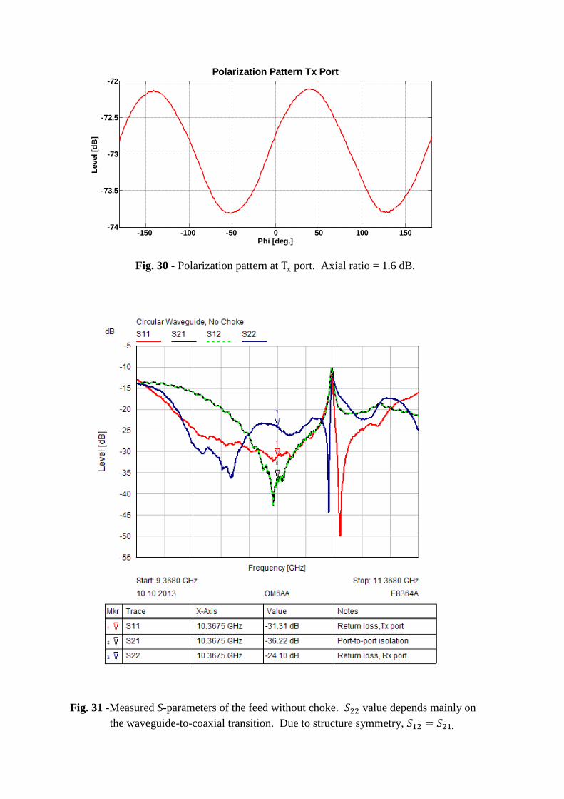
Fig. 30 - Polarization pattern at Tx port. Axial ratio = 1.6 dB.
Fig. 31 -Measured S-parameters of the feed without choke. 𝑆22 value depends mainly on the waveguide-to-coaxial transition. Due to structure symmetry, 𝑆12 = 𝑆21.
-150 -100 -50 0 50 100 150-74
-73.5
-73
-72.5
-72Polarization Pattern Tx Port
Leve
l [dB
]
Phi [deg.]

4.2 Chaparral Style Choke in Flush Position
A Chaparral style choke in flush position is shown in Fig. 32.
Fig. 32 - Feed fitted with Chaparral style choke.
Radiation patterns are shown in Figs. 33 and 34. The associated polarization pattern appears in Fig. 35.
Fig. 33 - E-plane cuts of feed’s radiation pattern with Chaparral style choke in Cartesian coordinates.
-150 -100 -50 0 50 100 150-140
-130
-120
-110
-100
-90
-80
-70
Theta [deg.]
Leve
l [dB
]
Chaparral Choke, Flush Position, E-Plane
Rx port Tx port

Fig. 34 - H-plane cuts of feed’s radiation pattern with Chaparral style choke in Cartesian coordinates.
Fig. 35 - Polarization pattern. Axial ratio for Tx port =1.4 dB; for Rx port, axial ratio =1.2 dB.
S – parameters are plotted in Fig. 36.
-150 -100 -50 0 50 100 150-140
-130
-120
-110
-100
-90
-80
-70
Theta [deg.]
Leve
l [dB
]
Chaparral Choke, Flush Position, H-Plane
Rx portTx port
-150 -100 -50 0 50 100 150
-73.6
-73.4
-73.2
-73
-72.8
-72.6
-72.4
-72.2
Phi [deg.]
Leve
l [dB
]
Polarization Pattern, Chaparral Choke, Flush Position
Tx portRx port

Fig. 36 - Measured S-parameters of the feed with Chaparral choke. 𝑆22 value depends mainly on the waveguide-to-coaxial transition. Due to the structure symmetry, 𝑆12 = 𝑆21.
4.3 Dual-Mode Horn
The radiation pattern of a dual-mode feed horn was also measured using an LP antenna. See Fig. 37.
Fig. 37 - Test of dual-mode horn feed in anechoic chamber equipped with Nearfield Systems Inc. positioners and software. Step resolusion is 0.0125 deg., repeatibility is 0.03 deg.

Comparison of calculated and measured radiation patterns are plotted in Fig. 38.
Fig. 38 - Radiation patterns of feed fitted with dual-mode horn in Cartesian coordinates. Tx port was active.
The associated polarization pattern is shown in Fig. 39.
Fig. 39 - Polarization pattern. Axial ratio for Tx port = 1 dB.
0 50 100 150 200 250 300 350-50
-40
-30
-20
-10
0
Theta [deg.]
Leve
l [dB
]Dual Mode Horn
E plane measuredH plane measuredE plane calculatedH plane calculated
0 50 100 150 200 250 300 350
-1
-0.8
-0.6
-0.4
-0.2
0
Phi [deg.]
Leve
l [dB
]
Polarization Pattern, Dual-mode Horn, Tx Port

Fig. 40 - Measured S-parameters of the feed with dual-mode horn. 𝑆22 value depends mainly on the waveguide-to-coaxial transition. Due to the structure symmetry, 𝑆12 = 𝑆21.
4.4 Kumar Choke
A feed assembly employing a Kumar (VE4MA) choke is shown in Fig. 41. The polarization pattern measurements of this feed and the following feed for a deep reflector were performed using two CP antennas, one of which was a dual-mode horn. The polarization pattern was then again measured using a double-ridged horn antenna. Co- and cross-polarization patterns are shown in Fig. 42.
Fig. 41 - Kumar choke under test.
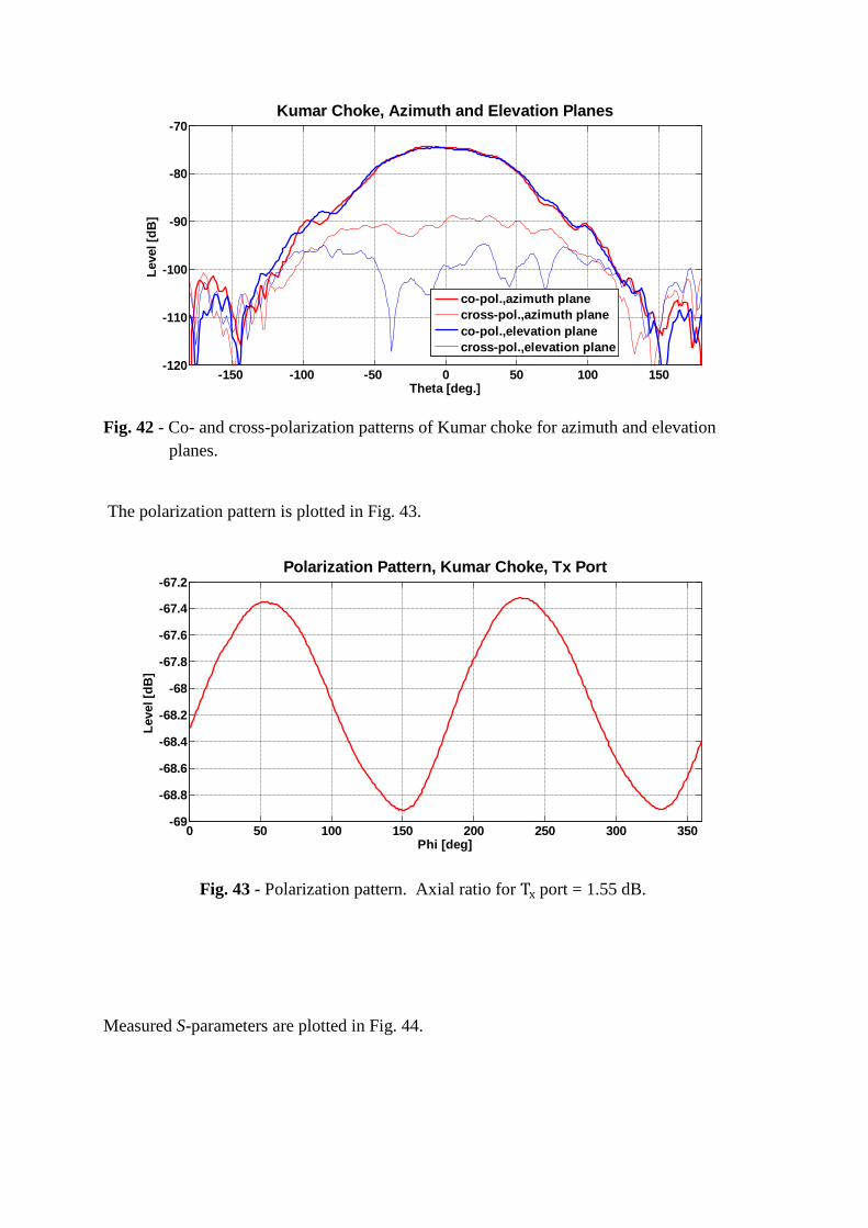
Fig. 42 - Co- and cross-polarization patterns of Kumar choke for azimuth and elevation planes.
The polarization pattern is plotted in Fig. 43.
Fig. 43 - Polarization pattern. Axial ratio for Tx port = 1.55 dB.
Measured S-parameters are plotted in Fig. 44.
-150 -100 -50 0 50 100 150-120
-110
-100
-90
-80
-70
Theta [deg.]
Leve
l [dB
]
Kumar Choke, Azimuth and Elevation Planes
co-pol.,azimuth planecross-pol.,azimuth planeco-pol.,elevation planecross-pol.,elevation plane
0 50 100 150 200 250 300 350-69
-68.8
-68.6
-68.4
-68.2
-68
-67.8
-67.6
-67.4
-67.2
Phi [deg]
Leve
l [dB
]
Polarization Pattern, Kumar Choke, Tx Port
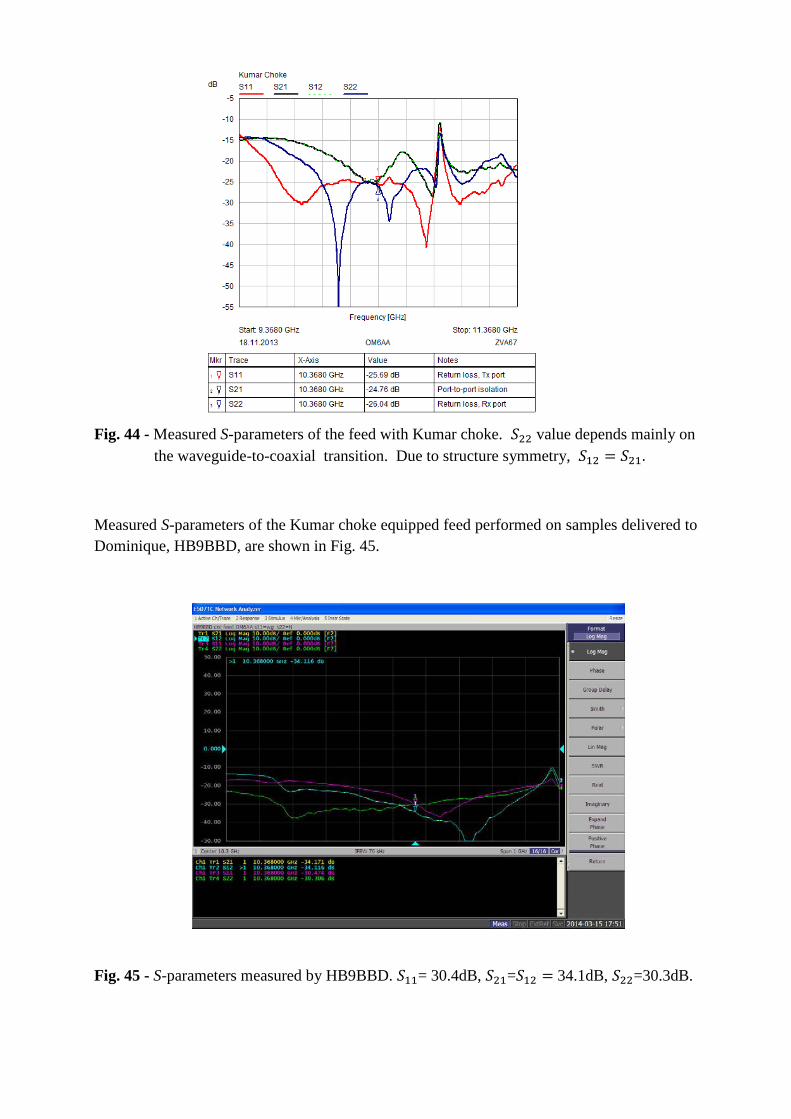
Fig. 44 - Measured S-parameters of the feed with Kumar choke. 𝑆22 value depends mainly on the waveguide-to-coaxial transition. Due to structure symmetry, 𝑆12 = 𝑆21.
Measured S-parameters of the Kumar choke equipped feed performed on samples delivered to Dominique, HB9BBD, are shown in Fig. 45.
Fig. 45 - S-parameters measured by HB9BBD. 𝑆11= 30.4dB, 𝑆21=𝑆12 = 34.1dB, 𝑆22=30.3dB.

4.5 Choke for Deep Dish
These measurements were performed with the same antenna configuration as for the feed equipped with the Kumar choke. See Fig. 46.
Fig. 46 - Feed with choke for deep dish; in anechoic chamber.
Fig. 47 - Co- and cross-polarization patterns of choke for deep dish.
Measured radiation patterns, S-parameters and polarization patterns are shown in Fig’s 47-49 respectively.
-150 -100 -50 0 50 100 150-120
-110
-100
-90
-80
-70
Theta [deg.]
Leve
l [db
]
Choke for Deep Dish, Azimuth and Elevation Planes
co-pol.,azimuth planecross-pol.,azimuth planeco-pol.,elevation planecross-pol.,elevation plane

Fig. 48- Plots of polarization patterns measured with a linear antenna (red) and a CP antenna (blue).
From the LP plot, axial ratio = max-min = 1.5 db. The difference between maximum and minimum of the CP plot represents a maximum polarization loss (of 0.15 dB) between the two CP antennas. The difference between mean values of the two plots plus 3dB represents the difference between antenna gains.
0 50 100 150 200 250 300 350-75.5
-75
-74.5
-74
-73.5
-73
-72.5
-72
-71.5
Phi [deg.]
Leve
l [db
]
Polarization Pattern, Choke for Deep Dish, Tx Port
CP antennaLP antenna

Fig. 49- Measured S-parameters of the feed with choke for deep dish. 𝑆22 value depends mainly on the waveguide-to-coaxial transition. Due to the structure symmetry, 𝑆12 = 𝑆21.
5. Feed Gain Factor
CST MW software was used to calculate the gain factors (also referred to as parabolic antenna efficiency) of our feeds. For the first step we calculated E-field radiation patterns of all feeds with 5 degree increments for angles φ and θ. Thus, the far field pattern was used as a far field source for excitation of parabolic reflectors with variable f/D ratios in the second step. The dish diameter was defined as 30 λ, i.e. 868.056 mm. Obstruction of the parabolic reflector by a specific feed was modeled by subtracting appropriate conductive area from the associated parabolic reflector’s surface. Calculated gain was converted to efficiency and plotted in Fig. 50.

Fig. 50 – Antenna efficiency for various feeds
In a trade-off of ease-of-fabrication for slightly lower performance, the relatively lower efficiency of the Kumar choke is attributed to this device’s higher back-lobe radiation. This choke exhibits somewhat better efficiency when used with waveguides having inside diameters of about 0.7 – 0.77 λ [24]. A Super-VE4MA or a Chaparral choke positioned a few tenths lambda behind the waveguide aperture would most likely achieve better performance for dishes with f/D ratios of about 0.35 – 0.4. However, by employing an iris matching technique, it is possible to interface the septum polarizer to most currently published waveguide chokes or horns.
Summary and Conclusion
EME’s transition from linear polarization to more-effective circular polarization is a challenge for ham radio operators using the 3 cm band. CP promotes increased stability and reliability during transmission as on the lower microwave bands, resulting in more successful EME contacts.
Work on the feed is ongoing. At the time of the editorial deadline, the working team is designing features to accommodate two waveguide ports (for Rx and Tx ports), a Super-VE4MA ckoke and a horn suitable for shallow dishes with f/D ratio’s of 0.7 – 0.8.
Several feeds were fabricated by two sources enabling comparisons to determine whether manufacturing tolerances affect the results. These facilities were the Mechanical Engineering Department machine shop at Czech Technical University in Prague and the workshop of Bert Moderman – PE1RKI.
Comprehensive measurements confirmed the integrity of the design in accordance with specified input requirements. Agreements between calculated and measured values for radiation patterns, impedance match, and port-to-port isolation are excellent. The only parameter showing deviation from calculated values is the axial ratio. This was caused by the
0.25 0.275 0.3 0.325 0.35 0.375 0.4 0.425 0.45 0.475 0.5 0.525 0.55 0.575 0.6 0.625 0.65 0.675 0.7 0.725 0.75 0.775 0.805
101520253035404550556065707580859095
100
Parabolic Dish f/D [ratio]
Para
bolic
Dis
h Ef
ficie
ncy
[%]
Dish Antenna Efficiency
Kumar - VE4MADual-mode - W2IMUChaparral - FlushDeep Dish Choke
Dish Diameter = 30 lambda

omission of PCB vias in the 3D electromagnetic simulations in order to decrease simulation times. Nevertheless, we achieved measured axial ratios between 0.9 dB and 1.6 dB, which is still very good. Axial ratios with a fairly large margin meet the criteria for this parameter, which is generally 3 dB [25].
Mechanical drawings of the feed appear in the appendix. Additional drawings of horns and related radiation parts will be available at the primary author`s website, www.om6aa.eu , in the near future.
Complete, ready-made feeds customized for specific f/D applications may be purchased from Bert Moderman, PE1RKI. His email is [email protected] .
If you plan to machine the feed yourself, you may obtain only the PCB from Peter Kasparek, OK2ULQ. His email is [email protected] .
Acknowledgements The authors would like to express their thanks to Mr. Robert Valenta for his for continuing technical and language support. Additionally, we thank RFspin s.r.o. [26], for the use of CST MW Studio software. References for part 2 [16] Galuscak Rastislav, „Septum Feed Revisited”, DUBUS 4/2004, ISSN 1438-3705 [17] Hazdra P., Galuscak R., Mazanek M., „Optimization of prime-focus circular waveguide feed with septum polarization transformer for 1.296 GHz EME station”, COST 284 paper at EuCAP in Nice, 6-10 Nov. 2006 [18] Schafai L., Kishk A.A.,Itripiboon A., Bridges E. „Performance of corrugated feeds with
simple corrugation shapes”, Int.Symp.Digest, AP, 21,May 1983, pp.586-588
[19] Revue HYPER „Speciale E.M.E. ”, 15.7.1998, No.125, pp.9-17 [20] Wade P. – W1GHZ, „Septum Feeds - Tolerances and Sensitivity” DUBUS 1/2013, ISSN 1438-3705 [21] Computer Simulation Technology, available online at: https://www.cst.com/ [22] Skobelev S.P., et al. „Optimum geometry and performance of a dual-mode horn modification”, IEEE Antennas and Propagatation Magazine, vol. 43, pp. 90 - 93, February 2001
[23] Kishk, A.A.., „Simple primary focus feeds for deep reflectors”, IEE Proceedings, Vol. 136, Pt. H, No. 2, APRIL 1989 [24] Wade P. – W1GHZ, „Feeds for Parabolic Dish Antennas, Chapter 6”, Microwave Antenna Book, available online at: http://www.w1ghz.org/antbook/chap6-3.pdf

[25] Gao Steven (Shichang), Qi Luo and Fuguo Zhu, „Circulary Polarized Antennas”, ©2014 John Wiley & Sons, Ltd, United Kingdom, ISBN 978-1-118-37441-2 [26] RFspin s.r.o., available online at: http://www.rfspin.cz/en/


