circular 33/00-9-1 test procedures adr 33/00-brake …rvcs.dotars.gov.au/tfi manual/circular...
TRANSCRIPT
CIRCULAR 33/00-9-1
TEST PROCEDURES
ADR 33/00-BRAKE SYSTEMS FOR MOTOR CYCLES
AND MOPEDS
“A Guide for Inspectors”
This Circular is relevant to the Third Edition of the
Australian Design Rules gazetted as
National Standards under the Motor Vehicle Standards Act 1989.
Issue 2: Page 1 of 31 CIRCULAR 33/00-9-1

CIRCULAR 33/00-9-1 Page 2 of 31 Issue 2:

CONTENTS
Page
1 SCOPE 5
2 SELECTION OF TEST VEHICLES 5
3 IDENTIFICATION OF TEST VEHICLES 5
4 NUMBER OF TEST VEHICLES 5
5 EQUIPMENT 5
5.1 Brake Failure Indicator Operation Tests 5
5.2 Performance Tests 5
6 PROCEDURE 7
6.1 Brake Failure Indicator Tests 7
6.2 Performance Tests 8
7 ANALYSIS OF RESULTS 27
8 SUMMARY OF EVIDENCE REPORT 27
9 PROCEDURE FOR DESIGNS WITH CERTIFICATIONTO ALTERNATIVE STANDARDS 27
10 REFERENCES 27
ANNEX A
TEST EQUIPMENT DIAGRAMS 28
ANNEX B
BRAKE EFFORT TRANSDUCER MOUNTING 29
ANNEX C
Figure 1 Apparatus for Wetting Brakes 30
Description of Apparatus for Wetting Brakes 31
TEST PROCEDURES CIRCULAR 33/00-9-1
Issue 2: Page 3 of 31 CIRCULAR 33/00-9-1

CIRCULAR 33/00-9-1 Page 4 of 31 Issue 2:

1 SCOPE
This procedure when read in conjunction with otherCirculars issued by the Administrator, provides sufficientinformation, without reference to other standards, toconduct and audit tests related to Motorcycle and MopedBraking Systems as described in Australian Design RuleNo. 33/00 and Circular 33-2-1 Demonstration ofCompliance with Performance Requirements. Forconvenience reference to the ADR clause number isquoted in brackets against each appropriate paragraph ofthis procedure.The equipment, orders of accuracy and step by stepactions described in this procedure are drawn from thestandards and recommended practices quoted in the ADRand from accepted laboratory and testing practices.While conformance with this procedure is sufficient todemonstrate compliance with the ADR, other equipment,orders of accuracy and procedures may be used providedit can be shown that they demonstrate compliance withthe ADR.This ADR requires validation by test in two specificareas, these being:-(i) Design Criteria and,(ii) Minimum Operational PerformanceThis procedure is intended primarily as a guide forofficers of the Australian Department of Transport andCommunication or Agents acting on behalf of theAdministrator when they carry out audit inspections ofTest Facilities or witness tests for compliance with theADR. This and other Circulars dealing with TestProcedures for ADRs may also be useful to vehiclemanufacturers and testing organizations.Nothing in this Circulars, however, absolves themanufacturers from complying with the requirements asspecified in the ADR which always remains the primaryreference.
2 SELECTION OF TEST VEHICLES
The selection of test vehicle or vehicles is to be carriedout in accordance with the implementation procedure asdetailed in Circular 33-2-1 and Circular 33-2-2, Selectionof Test Vehicles.See Circular 0-12-1 Section 5 Worst Case “Criteria”
3 IDENTIFICATION OF TEST VEHICLES
All test related components of the test vehicle(s) shall berepresentative of the design conditions as reflected in theproduction drawings.In most cases the test vehicle(s) will be assembled usingproduction components which have passed throughnormal quality assurance procedures. If prototypecomponents are used they should be individuallyinspected for both dimensional and material specificationcompliance detailed in their respective drawings.For each test program all relative components are to beuniquely identified by part number, drawing number andrevision or issue status. Such information is to beincluded in all test records and reports.
Component identification lists should include at least thefollowing:-(i) All components of the braking system(ii) Vehicle Body Fairings, if fitted(iii) Wheels and Tyres
4 NUMBER OF TEST VEHICLES
The selection of number of test vehicles is to be carriedout in accordance with the implementation proceduresdescribed in Circular 33-2-1.
5 EQUIPMENT
The following equipment details minimum requirementsto conduct ADR 33/00 tests. Alternative equipment orsystem approaches would be valid if their accuracy andresponse characteristics can be shown to demonstratecompliance with the ADR.5.1 Brake Failure Indicator Operation Tests
5.1.1 Instrumentation5.1.1.1 Measurement. The following parametersare to be determined during the test:(i) pressure(ii) service brake effort.Pressure gauges of a suitable range are requiredfor hydraulic line pressure, power unit and powerassist unit storage pressure. Service brake effortcan be determined by hydraulic or electronictransducers.5.1.1.2 Recording. A recording or displaysystems would, depending on transducer type, beby pressure gauge or via signal conditioning tometer or recorder packages. All results are to beentered on a suitable data sheet.5.1.1.3 Order of Accuracy Except wherespecified in the ADR or referred documents theorders of accuracy indicated in this procedure aresuggested as being commercially achievable andshould be taken as a guide. Instrumentation oflesser accuracy is acceptable provided it is takeninto account in determining the certainty ofresults. Pressure gauges are to be scaled andcalibrated to ensure an accuracy in the order of2.5%. Total system accuracy for brake effortdetermination should be no less than 5%.5.1.1.4 Calibration Pressure gauges are to becalibrated in accordance with Circular 0-12-3.Hydraulic brake effort equipment should becalibrated against a reference force testing systemat least every six months. Electronic brake effortequipment should be calibrated prior to use ineach test.
5.2 Performance tests5.2.1 Basic EquipmentThe following basic equipment is required:(i) test track(ii) 30% gradient test slope(iii) water conditioning equipment(iv) vehicle mass determination equipment(v) ambient temperature determination
TEST PROCEDURES CIRCULAR 33/00-9-1
Issue 2: Page 5 of 31 CIRCULAR 33/00-9-1
equipment(vi) wind speed determination equipment(vii) instrumentation5.2.1.1 Test track. A suitable test site would besubstantially flat with no upward gradient greaterthan 1%. If any upward gradient exists alldecelerations shall be conducted down thatgradient. The test track shall be of sufficientlength to satisfy the distance requirements of thefade cycle. The track can take the form of a circuitor a straight track with suitable turning facilities ateach end. Lane width identification is required.For two wheeled vehicles a straight lane width of2.5 m and for three wheeled vehicles the overallwidth plus 1.55 m.5.2.1.2 Test slopes.The 30% gradient test slope isrequired for parking brake tests. This slope is bestsurfaced with flat clean finish concrete.5.2.1.3 Water condit ioning equipment.Equipment described in Annex C is required toconduct tests on brakes under wet conditions.Calibration of water flow shall be allowed for inthe construction of this equipment.5.2.1.4 Mass Determination Equipment.Suitable mass determination equipment is requiredto measure vehicle mass and front/rear weightdistribution. This equipment shall satisfy thecalibration requirements of Circular 0-12-3.5.2.1.5 Temperature Determination Equipment.A mercury in glass or thermocouple typethermometer is required for the measurement ofambient temperatures. An accuracy of no less than1 degree C would be necessary.5.2.1.6 Wind Speed determination. Ananemometer with an operational accuracy of 5%in the 0-20 km/h range would be suitable.5.2.2 Instrumentation. This instrumentationdescription is a minimum system based on the useof general instrument packages and does not coversystems incorporating purpose built counters orprocessor type data loggers. It should be notedthat careful selection of light test equipment isdesirable as some difficulty can be encountered inachieving the required test mass conditions withthe vehicle fully instrumented.5.2.2.1 Measurement.The following parametersare to be determined and in some cases permanentrecording with respect to a fixed time base isrequired:(i) Displacement (distance)(ii) Velocity(iii) Acceleration(iv) Service brake actuation effort(v) Park brake actuation effortRefer to Annex A for a general arrangement of avehicle instrument package. Each function blockof this general arrangement will be discussedindividually.5.2.2.1.1 Fifth Wheel. A suitable fifth wheel,light beam doppler system or displacement
sensing device is required and would incorporatepulse signal generation capability to satisfy theaccuracy requirements as detailed in 5.2.2.3.5.2.2.1.2 Displacement Counter.A pulse counterwith a minimum 10 kHz input capability with aminimum six digit display is required to provide asatisfactory resolution and level of accuracy. Thecounter is to include start and reset input facilities.5.2.2.1.3 Velocity Counter. A frequency countersuitable for a 10 kHz signal would be satisfactory.The counter would require remote reset andstop/hold input facilities.5.2.2.1.4 Brake Signal. Provision is to be madefor a control trigger signal to be generated onactuation of the service brake. This signal is to beproduced within the first 3 mm of pedal/levertravel. The control signal can be sourced from thebrake light switch or from a suitably mountedmicro switch at the brake pedal. Depending on thecounter system utilized, some form of signalconditioning may be required. Isolation switchingof this signal from the displacement counter isrequired for some sections of the test procedure.5.2.2.1.5 Acceleration Sensing.An accelerometerof low frequency response and signal conditioningequipment is satisfactory for determiningsustained decelerations. Operator monitoringfacilities can be provided by use of a calibratedanalogy meter or by direct use of the chartrecorder.5.2.2.1.6 Brake Actuation Effort. Brakeactuation effort can be measured by a ‘Mintex’type hydraulic force gauge or an electronic forcemeasurement system. If a hydraulic system isutilized a pressure transducer is required tofacilitate recording of sustained pedal effort.Either transducer output would requirecondit ioning to suit the recorder inputrequirements.5.2.2.1.7 Recorder.A chart recorder is required tolog sustained decelerations and sustained pedaleffort. Such a recorder would have full scale writeresponse of less than 0.1 s and chart speedsufficient to ensure that braking events could beadequately resolved (50 mm/s is consideredappropriate)5.2.2.2 Recording.All results are to be logged onsuitable data sheets with the exception of sustaineddecelerations and sustained braking effort whichwould be logged by chart recorder. It is alsoacceptable to use digital equipment to monitorthese parameters provided that the sample rate issufficient to resolve braking events (0.1 s isconsidered appropriate)5.2.2.3 Order of Accuracy. Except wherespecified in the ADR or referred documents, thefollowing order of accuracy is considered to becommercially achievable and should be taken as aguide. Instrumentation of lesser accuracy isacceptable provided it is taken into account in
CIRCULAR 33/00-9-1 TEST PROCEDURES
CIRCULAR 33/00-9-1 Page 6 of 31 Issue 2:

determining the certainty of results.Displacement and velocity accuracy is dependanton fifth wheel calibration. Pulse generation in theorder of 100 mm/pulse is satisfactory and wouldprovide no correction of display count if afrequency sample rate of 1 second is used in thedetermination of velocity.A surveyed road distance of some 5 km long maybe used for verification of the distance measuringequipment.Accuracy of 1% is achievable with anaccelerometer system. Service and parking brakeeffort is to be determined with an accuracy of noless than 5%. The chart recorder time base is tobe accurate to within 2%.5.2.2.4 Calibration.Pressure gauges, stopwatchesand tachometers are to be calibrated in accordancewith Circular 0-12-3. Hydraulic pedal effortequipment should be calibrated against a referenceforce testing system at least every six months.Electronic pedal effort equipment should becalibrated prior to use in each test.
6 PROCEDURE
6.1 Brake Failure Indicator Tests6.1.1 Preparation for Tests6.1.1.1 Review program. This test sequence isrequired to validate the system design in terms ofconditional operation of the failure lamp. Theconditions required to initiate illumination of thelamp will have been determined at the designstage. These conditions are detailed in Clause33.2.3.1. Dependant on brake system design oneor more of the following four parameters willrequire validation:(a) System line pressure failure;(b) Brake power unit supply pressure;(c) Brake fluid level;(d) Electrical failure to antilock or proportioningsystems.6.1.1.2 Setting up:- Parameter (a): Fit pressure gauges to mastercylinder outlets or, if fitted, to slave cylinderoutlets associated with a booster unit. Fit eachoutlet with an adjustable bleed valve. Provision tofit a force transducer to the brake pedal and thebrake hand lever is to be made. The mounting ofthis transducer is to comply with the requirementsof Clause 33.4.10. Mount the associated forceindicator in a convenient position for operator use.Refer to Annex B for guidelines on the installationof the effort transducer when related to hand leveroperation.- Parameter (b): Fit a pressure gauge to the brakepower unit or units so that the supply pressure canbe monitored. Fit a bleed valve in such a positionso that supply pressure can be progressivelyvented.- Parameter (c): Determine the design maximum
fluid volume for the master cylinder reservoir.This is to be determined by reference to theproduction drawings or by practical measurementas follows. Fit a bleed valve to a master cylinderoutlet. Connect the discharge outlet of this valveto a burette or graduated cylinder. Open the valveand pass fluid from the master cylinder until thefluid drains into the measuring cylinder. Close thevalve and top up the reservoir to the design fluidlevel. Record measured fluid volume of reservoir.- Parameter (d): A means by which the power toelectrical components can be broken is required.6.1.1.3 Review Instrumentation. Ensure that allinstrumentation zero and span calibrations arecorrect. Record any instrument correction factorsas required.6.1.2 Tests6.1.2.1 Parameter (a): System line pressurefailure.(i) Ensure the bleed valves are fully closed.(ii) Start the engine and apply a sustained pedal orlever effort to the brake system approximatingnormal service use.(iii) Open one only bleed valve to provide a slowdrop in line pressure.(iv) Monitor the Brake Failure Indicator, linepressures and application effort.(v) On activation of the Failure Indicator recordline pressure for both the active and failed systemsand application effort.(vi) Stop the engine and restore the brakingsystem to normal function.(vii) Repeat this test sequence failing the alternatesystem.6.1.2.2 Parameter (b); Brake power unit supplypressure.(i) Start the engine.(ii) Ensure the power unit is fully charged andthen isolate the unit from the energy source.(iii) Record the fully charged pressure.(iv) Progressively vent the power unit untilactivation of the Brake Failure Indicator.(v) Record the pressure level on activation.(vi) Repeat procedure for any additional powerunits.6.1.2.3 Parameter (c): Brake fluid level.(i) Start the engine.(ii) Open the bleed valve at the master cylinderoutlet.(iii) Displace brake fluid to the measuring cylinderby controlled pedal or lever movement. (iv) Onactivation of the Brake Failure Indicator close thebleed valve and stop the engine.(v) Determine and record the volume of brakefluid discharged by this procedure.(vi) Restore the braking system to normalfunction.(vii) Calculate the percentage of fluid displacedwith respect to the total volume of the reservoir.6.1.2.4 Parameter (d): Electrical failure to
TEST PROCEDURES CIRCULAR 33/00-9-1
Issue 2: Page 7 of 31 CIRCULAR 33/00-9-1

antilock or proportioning systems.(i) Start the engine.(ii) Isolate power supply to the brake systemcontrol circuitry.(iii) Check for Brake Failure Indicator operation.(iv) Stop the engine and restore the brake systemto normal function.6.1.3 Determination of Results. From the datarecorded, compliance can be determined byreference and comparison with the minimumrequirements as detailed in the ADR Clause33.2.3.1. All original data used for determiningresults is to be retained as either part of the TestingFacility’s internal report or in a separate originaldata file. In any case the direct readings and thecomputation showing the method of determiningthe results are to be given in the internal report.6.1.4 Reporting of Results. For these tests acomplete internal report giving a full descriptionof the material tested, equipment used, results andorder of accuracy is to be prepared. Forsubmission to the Administrator the reportnumber(s) for the above test(s) is to be entered inthe appropriate section of the Summary ofEvidence Report - see Section 8.
6.2 Performance Tests6.2.1 Preparation for Tests6.2.1.1 Review program. Ensure that the testvehicle is in accordance with Circular 33-2-2.Confirm the test program sequence determined iswithin the constraints of Clause 33.3.1.6.2.1.2 Setting up6.2.1.2.1 Instrumentation. The test vehicle is tobe fitted with suitable instrumentation so that thefollowing parameters can be monitored:(i) Displacement (distance)(ii) Velocity(iii) Acceleration(iv) Brake pedal/lever effort(v) Parking brake effort (if applicable)Refer to Annex A for the general arrangement ofthe instrumentation package. Install the individualcomponents related to Displacement, Velocity andAcceleration. Refer to Annex B for guide lines onthe installation of the braking effort transducerwhen related to hand lever operation. Whenlocating these components provision for theinterconnection of components, the installation ofballast if required and operator visual access to theappropriate displays should be made. Care isrequired to ensure the vehicle mass requirementsas detailed in Clause 33.1.3 are achieved.Provisioning of a trigger signal is required toindicate commencement of a deceleration cycle.Such a signal is to be initiated by brake pedal/levermovement and can utilize the test vehicle brakesignal lamp circuit or a suitable switching systemmounted at the pedal. In either case the systemmust be capable of being adjusted so thatactivation occurs within the first 3 mm of pedal
travel.This signal is to be connected so that on activation:- the displacement counter is reset, countinginitiated; and - the velocity count is inhibited andthe current value held.Depending on the particular instrumentation usedit may be necessary to condition the trigger signalwith ‘debounce’ circuits etc to provide satisfactoryinterface. It is recommended that an event counterbe connected to this source and a decelerationcycle counter as required.The parking brake effort package need only beinstalled for that particular test sequence.6.2.1.2.2 Vehicle preparation. In preparation ofthe test vehicle, provision must be made to inducefailure of specific functions of the brake system.These functions are:- hydraul ic fai lure of each independantsub-system- failure of a brake antilock system- failure of a variable proportioning system and- failure of the energy supply and storagecomponents of a power unit or power assist unit.The failure of a hydraulic sub-system can beinduced by the fitting of a vent valve and fluidcollection facility to each hydraulic circuit.The fitting of an electrical power isolation switchto an antilock control circuit will simulate totalfailure of such a system.A variable proportioning system can be renderedinoperative by disconnection of the control inputof a mechanical system or the isolation of theelectrical power source of an electronic system.Power units and power assist units are to be fittedwith a suitable valve to negate continued supplyfrom the energy source. The energy storage unit isto be fitted with a pressure gauge and vent valveand these components are to be mounted so thatmonitoring and valve control can be carried out bythe test operators.Install water conditioning equipment to the testvehicle. It is recommended that this be donebefore final check of the test vehicle mass and loaddistribution. The equipment and stored watermass can significantly influence test conditions ifit is used for other than the wet brake test.The test vehicle’s braking system and power unitare to be adjusted to meet the vehiclemanufacturer’s specifications.Tyre inflation pressures are to be set to themanufacturers specification for maximum loadedvehicle mass.The performance test procedures require tests tobe conducted under laden motorcycle masscondition. This condition is defined in Clause33.1.3. Use ballast if required to achieve the testmass. (Sealed sand bags are recommended).Each vehicle load condition is to be confirmed byuse of suitable mass determination equipment.Provision is to be made on the test site of a lane
CIRCULAR 33/00-9-1 TEST PROCEDURES
CIRCULAR 33/00-9-1 Page 8 of 31 Issue 2:

2.5 m wide in the case of two wheeled vehiclesand overall vehicle width plus 1.55 m wide in thecase of three wheeled vehicles. This lane is to beidentified by marking or placement of suitableindicators.6.2.1.3 Review instrumentation.Ensure that allinstrumentation is securely restrained. Conductpretest calibration procedures as required for eachinstrument sub-system (not to involve dynamicbraking). Record any instrument correctionfactors. Accurate fifth wheel calibration isessential for total instrumentation packageaccuracy and therefore frequent checks, aspermitted, are to be carried out over a surveyedtest distance.6.2.1.4 Determinat ion of ‘MaximumMotorcycle Speed’ Prior to commencement ofthe test program, it is necessary to establish thetest vehicle ‘Maximum Vehicle Speed’ as definedin Clause 33.1.4. This may be established bycalculation or on the basis of a test, undermaximum acceleration from a standing start for1.6 km. at the Laden Motor Cycle Mass using atest site as described in Section 5.2.1.1. This resultis to be recorded on the test data sheets.6.2.2 TestsThe twenty-six (26) test ‘items’ as described in theADR will be presented as individual proceduresand as such can be sequenced to suit each uniquetest program, within the constraints of Clause33.3.1 of the ADR.
The following test conditions are to be adhered toduring the test program.- All test items must be conducted in sequenceduring the test program.- Manual adjustment of the brakes can only becarried out on two occasions, this being oncompletion of Test Item 4 and 10.- No repair, or replacement, of brake systemcomponents may be carried out.- For all effectiveness and partial failure tests thevehicle must be maintained within the defined testlane.- All deceleration tests shall be conducted with theengine and transmission disengaged if there isprovision to do so.- If the required initial speed is not attainable bythe test vehicle the test initial speed shall be within15 km/h of the vehicle’s maximum speed.- For all effectiveness and partial failure tests:
: no part of the vehicle shall move outside astraight lane 2.5 metres in width in the case of2-wheeled vehicles, and ‘Overall Width’ plus1.55 metres in the case of 3-wheeled vehicles.The vehicle shall be positioned at the centre ofthe lane at the commencement of thedeceleration; and: lockup shall not occur on any wheel unlesssuch lockup results from the proper functioningof an ‘Antilock System’.
TEST PROCEDURES CIRCULAR 33/00-9-1
Issue 2: Page 9 of 31 CIRCULAR 33/00-9-1

6.2.2.1 Test Item 1 ‘Pre-Test Instrumentation Check’.(Clause 33.5.1)This test provides for a series of decelerations to checkthe function of the test equipment etc.Test Conditions:Maximum number of decelerations = 20Maximum initial velocity = 50 km/hMaximum sustained deceleration = 3.1 m/s2
Procedure:This test sequence is not subject to environmental
constraints and any number of decelerations up to 20 maybe conducted. Prior to conducting any decelerationchecks, calibrate the fifth wheel and instrumentation as apackage over a measured test distance. See Section5.2.2.3. It is recommended that the deceleration testsequence be used by the operator to confirm test controltechnique for parameters such as sustained decelerationand sustained pedal effort.During this test, record no less information than thatshown on the following sample data sheet.
RESULTS: ‘Pre-Test Instrumentation Check’ (Test Item 1)Decel Initial Stopping Sustained Maximum Maximum AverageNo. velocity distance decel pedal effort lever effort decel (calc)
(km/h) (m) (m/s2) (N) (N) (m/s2)1
2
3
4
5
6
7
8
9
10
11
12
13
14
15
16
17
18
19
20
Calculate Minimum Average Deceleration using the following equation:Av decel = ((Init. velocity)/3.6)2
2x (Stopping dist)
Comments:
CIRCULAR 33/00-9-1 TEST PROCEDURES
CIRCULAR 33/00-9-1 Page 10 of 31 Issue 2:
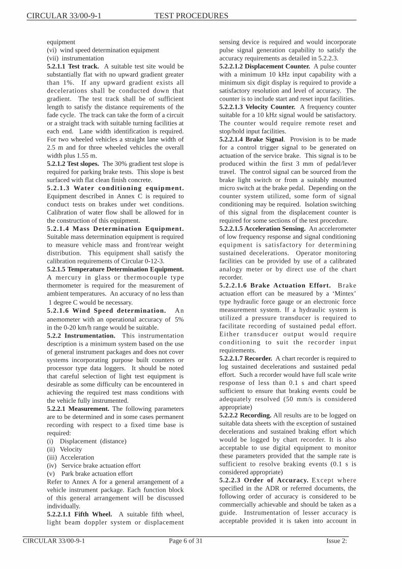
6.2.2.2 Test Item 2 ‘First Effectiveness Test’(Clause33.5.2) This test specifies required deceleration levelsfrom two particular initial speed ranges. Thesedeceleration levels must be achieved at least once in nomore than six attempts in each case. If the test vehiclemaximum speed is less than the initial speed requirementthe initial velocity shall be as per Clause 33.4.9. This testis to be conducted using all service brake systems.Test conditions:Application mode = All service brakesInitial velocity = (i) 45-50 km/h
= (ii) 95-100 km/hBrake pedal effort = 40-405 NBrake lever effort = 20-250 NAmbient temperature = 0-40 degrees CWind component = not to exceed 15 km/h
opposing direction of vehicletravel
Acceptance criteria:Minimum average = 5.45 m/s2
deceleration (All initial velocity ranges)
Procedure:- Measure and record ambient temperature, wind speedand wind direction.- Accelerate the vehicle to a speed in excess of therequired initial velocity.- Place the transmission in the neutral position.- Coast down to required initial velocity and commencedeceleration.- Modulate the brake effort to achieve maximumretardation whilst monitoring display to ensure thatpermitted effort range is not exceeded.- Determine initial velocity, stopping distance,maximum brake control efforts and record on the testdata sheets.- Calculate minimum average deceleration.- Repeat test sequence as required but not exceeding atotal of six attempts.- This procedure is repeated for both required initialspeeds.During this test record no less information than thatshown on the following sample data sheet.
RESULTS: ‘First Effectiveness Test’ (Test Item 2)Test site : Date:Ambient temperature: degrees CWind speed: km/hWind direction relative to vehicle travelDecel Initial Stopping Maximum Maximum Average VehicleNo. velocity distance pedal effort lever effort decel (calc) within lane?
(km/h) (m) (N) (N) (m/s2) Y/NInitial Speed 45-50 km/h
1
2
3
4
5
6
Initial Speed 95-100 km/h
1
2
3
4
5
6
Calculate Minimum Average Deceleration using the following equation:Av decel = ((Init. velocity)/3.6)2
2x (Stopping dist)Comments:
TEST PROCEDURES CIRCULAR 33/00-9-1
Issue 2: Page 11 of 31 CIRCULAR 33/00-9-1

6.2.2.3 Test Item 3 ‘Effectiveness Test’. (Clause 33.5.3)(Independently actuated service brake systems). This testspecifies required deceleration levels from two particularinitial speed ranges. These deceleration levels must beachieved in no more than six (6) attempts in each case. Ifthe test vehicle maximum speed is less than the initialspeed required the initial velocity shall be as per Clause33.4.9. This test is to be repeated using each independentservice brake system.Test Conditions:Application mode = Each service brake independentlyInitial velocity = (i) 45-50 km/h
= (ii) 95-100 km/hMaximum pedal effort = 40-405 NMaximum lever effort = 20-250 NAmbient temperature = 0-40 degrees CWind component = not to exceed 15 km/h
opposing direction of vehicletravel.
Acceptance criteria:Minimum average = 2.40 m/s2
deceleration (All initial velocity ranges)
Procedure:- Measure and record ambient temperature, wind speedand wind direction- Accelerate the vehicle to a speed in excess of therequired initial velocity- Place the transmission in the neutral position- Coast down to required initial velocity and commencedeceleration- Modulate the brake effort to achieve maximumretardation whilst monitoring display to ensure thatpermitted effort range is not exceeded- Determine initial velocity, stopping distance,maximum brake control efforts and record on the testdata sheets- Calculate minimum average deceleration- Repeat test sequence as required but not exceeding atotal of six attempts- This procedure is repeated for both required initialspeeds and each independent systemDuring this procedure record no less information thanthat shown on the following sample data sheet.
DATA: ‘Effectiveness Test’ (Test Item 3)Test site : Date:Ambient temperature: degrees CService brake system:Decel Initial Stopping Maximum Average VehicleNo. velocity distance brake effort decel (calc) within lane
(km/h) (m) (N) (m/s2) Y/NInitial Speed 45-50 km/h
1
2
3
4
5
6
Initial Speed 95-100 km/h
1
2
3
4
5
6
Calculate Minimum Average Deceleration using the following equation:Av decel = ((Init. velocity)/3.6)2
2x (Stopping dist)Comments:
CIRCULAR 33/00-9-1 TEST PROCEDURES
CIRCULAR 33/00-9-1 Page 12 of 31 Issue 2:

6.2.2.4 Test Item 4 ‘First Burnishing Procedure’(Clause 33.5.4) This procedure permits brake burnishingto be conducted within the following constraints. If thevehicle maximum speed is less than the initial speedrequired the initial velocity shall be as per Clause 33.4.9.Conditions:Application mode = All service brakes as requiredMaximum number ofdecelerations = 200Initial velocity = 45-50 km/hMaximum pedal effort = 40-405 NMaximum lever effort = 20-250 NMaximum instantaneousdeceleration = 3.7 m/s2
Maximum distance travelled for eachdeceleration cycle = 1.6 km
Ambient temperature = 0-40 degrees CProcedure:- Measure and record ambient temperature.- Determine total number of decelerations.- Accelerate the vehicle to within the specified speedrange.- Retard the vehicle, monitoring brake control efforts,instantaneous acceleration and total distance.- Reset the distance counters.- Repeat sequence for the desired number of cycles.On completion of this procedure the brakes may beadjusted in accordance with the manufacturer’srecommendations.During this test record no less information than thatshown on the following sample data sheet.
RESULTS: ‘First Burnishing Procedure’ (Test Item 4)Test site : Date:Ambient temperature: degrees CDecel Initial Cycle Maximum Maximum Max. Inst.No. velocity distance pedal effort lever effort decel
(km/h) (m) (N) (N) (m/s2)Initial Speed 45-50 km/h
1
2
3
4
5
6
* * *
199
200
Comments:
TEST PROCEDURES CIRCULAR 33/00-9-1
Issue 2: Page 13 of 31 CIRCULAR 33/00-9-1

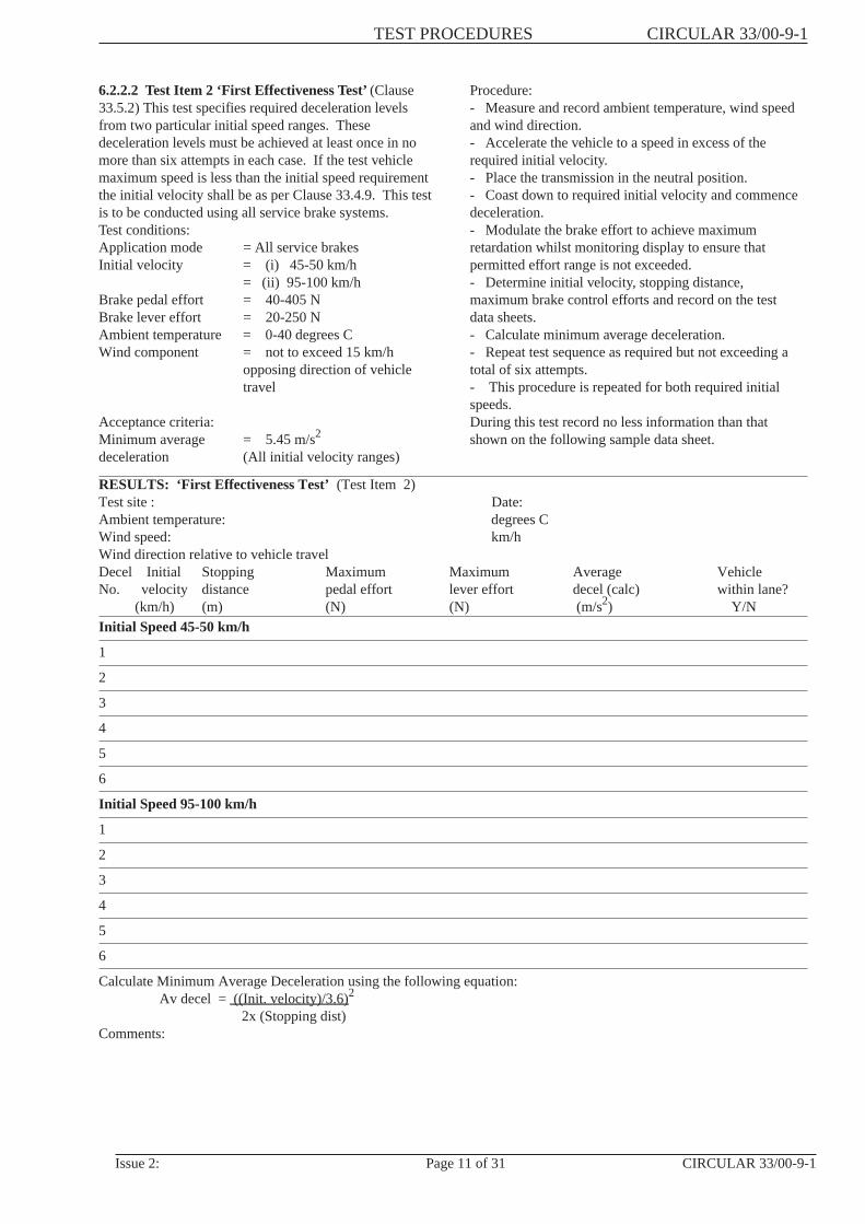
6.2.2.5 Test Item 5 ‘Second Effectiveness Test’(Clause33.5.5) This test specifies required deceleration levelsfrom four particular initial speed ranges. Thesedeceleration levels must be achieved in no more than sixattempts in the case of the first two speed ranges and nomore than four in the case of the last two speed ranges ifapplicable. Test to the fourth speed range is dependant onmaximum vehicle speed determined for the test vehicle.Tests are to be conducted using all service brake systems.Test Conditions:Application mode = All service brakesInitial velocity = (i) 45-50 km/h
(ii) 95-100 km/h(iii) 125-130 km/h
For vehicles of max (iv) within 15 km/h of maxspeed greater than speed (Clause 33.1.4)150 km/h onlyMaximum pedal effort = 40-405 NMaximum lever effort = 20-250 NAmbient temperature = 0-40 degrees CWind component = not to exceed 15 km/h
opposing direction of vehicletravel
Acceptance criteria:Minimum averagedeceleration = Velocity (i) - 6.85 m/s2
Velocity (ii) - 6.35 m/s2
Velocity (iii) - 6.05 m/s2
Velocity (iv) - 5.45 m/s2
Procedure:Determine tests to be conducted. ie. If Maximum VehicleSpeed is less than 150 km/h, then decelerations to thefirst three speed ranges only require testing. If theMaximum Vehicle Speed is greater than 150 km/h, thenall four speed ranges apply.- Measure and record ambient temperature, wind speedand wind direction.- Accelerate the vehicle to a speed in excess of therequired initial velocity.- Place the transmission in the neutral position.- Coast down to required initial velocity and commencedeceleration- Modulate the brake control effort to achieve maximumretardation whilst monitoring display to ensure that thelimits are not exceeded.- Determine initial velocity, stopping distance, maximumbrake control efforts and record on the test data sheets- Calculate minimum average deceleration.- Repeat test sequence as required but not exceeding atotal of six attempts in the case of the first two speedranges and four in the case of the last two if applicable.- This procedure is repeated for all required initialspeeds.During this procedure record no less information thanthat shown on the following sample data sheet.
CIRCULAR 33/00-9-1 TEST PROCEDURES
CIRCULAR 33/00-9-1 Page 14 of 31 Issue 2:
RESULTS: ‘Second Effectiveness Test’( Test Item 5)Test site : Date:Ambient temperature: degrees CWind speed: km/hWind direction relative to vehicle travelDecel Initial Stopping Maximum Maximum Average VehicleNo. velocity distance pedal effort lever effort decel (calc) within lane
(km/h) (m) (N) (N) (m/s2) Y/NInitial Speed 45-50 km/h
1
2
3
4
5
6
Initial Speed 95-100 km/h
1
2
3
4
For vehicles max speed 150 km/h or greater: Initial speed within 15 km/h of max speed1
2
3
4
Initial Speed 125-130 km/h
1
2
3
4
5
6
Calculate Minimum Average Deceleration using the following equation:Av decel = ((Init. velocity)/3.6)2
2x (Stopping dist)Comments:
TEST PROCEDURES CIRCULAR 33/00-9-1
Issue 2: Page 15 of 31 CIRCULAR 33/00-9-1

6.2.2.6 Test Item 6 ‘First Base Line Check Procedure’(Clause 33.5.6). This procedure establishes reference dataas required for procedures to be carried out later in thetest program. Tests are to be conducted using all servicebrake systems. This test procedure does not apply tomotorcycles with a maximum speed less than 50 km/hand mopeds.Test conditions:Application mode = All service brakesInitial velocity = 45-50 km/hMaximum pedal effort = 40-405 NMaximum lever effort = 20-250 NAmbient temperature = 0-40 degrees CWind component = not to exceed 15 km/h
opposing direction of vehicletravel
Acceptance criteria:Number of stops = Three (3)Sustained deceleration = 3.20 0.2 m/s2
Procedure:- Measure and record ambient temperature, wind speedand wind direction.- Accelerate the vehicle to a speed in excess of therequired initial velocity.- Coast down to required initial velocity and commencedeceleration.- Modulate the brake effort to achieve a sustaineddeceleration of 3.20 0.2 m/s2 by monitoring the realtime display of deceleration.- Rewind chart recorder to initial reference point.- Determine initial velocity and maximum brake controlefforts and record on the test data sheet.- Repeat test sequence to a total of three decelerations.- On completion of the test attach the chart recording tothe data sheet.During this procedure record no less information thanthat shown on the following sample data sheet.
RESULTS: ‘First Base Line Check Procedure’ (Test Item 6)Test site : Date:Ambient temperature: degrees CWind speed: km/hWind direction relative to vehicle travelDecel Initial Stopping Maximum MaximumNo. velocity distance pedal effort lever effort
(km/h) (m) (N) (N)Initial Speed 45-50 km/h
1
2
3
Average maximum pedal effort: .................(N) Average maximum lever effort: .................(N)Comments:
CIRCULAR 33/00-9-1 TEST PROCEDURES
CIRCULAR 33/00-9-1 Page 16 of 31 Issue 2:

6.2.2.7 Test Item 7 ‘Fade Test’(Clause 33.5.7) This testspecifies required deceleration levels to be achievedunder potential brake fade conditions. A total of tenconsecutive decelerations are to be conducted from aspecified initial speed range.Test conditions:Application mode = All service brakesInitial velocity = 95-100 km/hMinimum sustained = not less than 4.55m/s2
decelerationBrake pedal effort = 40-405 NBrake lever effort = 20-250 NMaximum distance between consecutivedecelerations = 650 mAmbient temperature = 0-40 degrees CWind component = not to exceed 15 km/h
opposing direction of vehicletravel
Acceptance criteria:Minimum sustained = 4.55 m/s2 for all stopsdecelerationProcedure:- Measure and record ambient temperature, wind speedand wind direction.
- Accelerate the vehicle at wide open throttle to a speedslightly in excess of the required initial velocity. (On thesecond and subsequent decelerations the distancetravelled from the start of the previous deceleration to thestart of the current one is not to exceed 650 m.- Commence deceleration.- Modulate the brake control effort to achieve asustained retardation not less than 4.55 m/s2
- The sustained deceleration level must be attainedwithin a time period such that the period of sustaineddeceleration is not less than three quarters of the period tostop.- On completion of the retardation the vehicle is to beimmediately accelerated at wide open throttle to therequired initial velocity..- The following information is to be recorded for eachcycle: Cycle distance, initial velocity, maximum pedaleffort, maximum lever effort and minimum sustaineddeceleration.- Repeat to a total of ten deceleration cycles.NOTE: Immediately on completion of this procedure,Test Item 8 must be conducted.During this procedure record no less information thanthat shown on the following sample data sheets.
RESULTS: ‘Fade test’ (Test Item 7)Test site : Date:Ambient temperature: degrees CWind speed: km/hWind direction relative to vehicle travel:Decel Initial Cycle Maximum Maximum MinimumNo. velocity distance pedal effort lever effort sustained
deceleration(km/h) (m) (N) (N) (m/s2)
Initial Speed 95-100 km/h
1 XXXXX
2
3
4
5
6
7
8
9
10
Comments:
NOTE: Proceed immediately to Test Item 8
TEST PROCEDURES CIRCULAR 33/00-9-1
Issue 2: Page 17 of 31 CIRCULAR 33/00-9-1
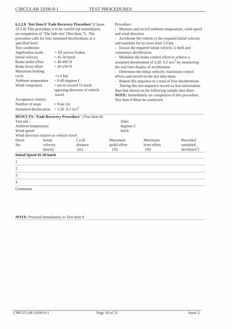
6.2.2.8 Test Item 8 ‘Fade Recovery Procedure’(Clause33.5.8) This procedure is to be carried out immediatelyon completion of ‘The fade test’ (Test Item 7). Theprocedure calls for four sustained decelerations at aspecified level.Test conditions:Application mode = All service brakesInitial velocity = 45-50 km/hBrake pedal effort = 40-405 NBrake lever effort = 20-250 NMaximum brakingcycle =1.6 kmAmbient temperature = 0-40 degrees CWind component = not to exceed 15 km/h
opposing direction of vehicletravel
Acceptance criteria:Number of stops = Four (4)Sustained deceleration = 3.20 0.2 m/s2
Procedure:- Measure and record ambient temperature, wind speedand wind direction- Accelerate the vehicle to the required initial velocityand maintain for no more than 1.6 km- Ensure the required initial velocity is held andcommence deceleration- Modulate the brake control effort to achieve asustained deceleration of 3.20 0.2 m/s2 by monitoringthe real time display of acceleration- Determine the initial velocity, maximum controlefforts and record on the test data sheet.- Repeat this sequence to a total of four decelerations
During this test sequence record no less informationthan that shown on the following sample data sheet.NOTE: Immediately on completion of this procedure,Test Item 9 Must be conducted.
RESULTS: ‘Fade Recovery Procedure’ (Test Item 8)Test site : Date:Ambient temperature: degrees CWind speed: km/hWind direction relative to vehicle travelDecel Initial Cycle Maximum Maximum RecordedNo. velocity distance pedal effort lever effort sustained
(km/h) (m) (N) (N) decel(m/s2)Initial Speed 45-50 km/h
1
2
3
4
Comments
NOTE: Proceed immediately to Test Item 9
CIRCULAR 33/00-9-1 TEST PROCEDURES
CIRCULAR 33/00-9-1 Page 18 of 31 Issue 2:

6.2.2.9 Test Item 9 ‘Fade Recovery Test’(Clause33.5.9) This test calls for a single sustained decelerationwhich is to be conducted immediately on completion ofTest Item 8.Test conditions:Application mode = All service brakesInitial velocity = 45-50 km/hAmbient temperature = 0-40 degrees CWind component = not to exceed 15 km/h
opposing direction of vehicletravel
Number of stops = One (1)Sustained deceleration = 3.20 0.2 m/s2
Acceptance criteria:Maximum Control = Average maximum controleffort (all systems) efforts as determined in Test
Item 6 + 90 N -45 N
Procedure:- Measure and record ambient temperature, wind speedand wind direction.
Accelerate the vehicle to the required initial velocityand maintain for no more than 1.6 km ..- Ensure that the required initial velocity is maintainedand commence deceleration.- Modulate the brake control effort to achieve therequired sustained deceleration of 3.20 0.2 m/s2 bymonitoring the real time display of acceleration
Determine initial velocity, maximum pedal effort,maximum lever effort, cycle distance and record on thetest data sheet.- On completion of the test attach the chart recording tothe data sheet.During this procedure record no less information thanthat shown on the following sample data sheet.
RESULTS: ‘Fade Recovery Test’ (Test Item 9)Test site : Date:Ambient temperature: degrees CWind speed: km/hWind direction relative to vehicle travelDecel Initial Stopping Maximum MaximumNo. velocity distance pedal effort lever effort
(km/h) (m) (N) (N)Initial Speed 45-50 km/h
1
Average maximum Pedal effort (from Test Item 6) ...................(N)Is the pedal effort achieved within +90 N -45 N ...................Average maximum lever effort (from Test Item 6) ...................Is the pedal effort achieved within +90 N -45 N ...................
Comments:
TEST PROCEDURES CIRCULAR 33/00-9-1
Issue 2: Page 19 of 31 CIRCULAR 33/00-9-1

6.2.2.10 Test Item 10, ‘Second Burnishing Procedure’.(Clause 33.5.10) This procedure permits brake burnishingto be conducted within the following constraints. If thevehicle maximum speed is less than the initial speedrequired the initial velocity shall be as per ‘Clause 33.4.9.Conditions:Application mode = All service brakes as
requiredmaximum number ofdecelerations = 35Initial velocity = 45-50 km/hBrake pedal effort = 40-405 NBrake lever effort = 20-250 NMaximum instantaneousdeceleration = 3.7 m/s2
Maximum distance travelled for eachdeceleration cycle = 1.6 kmAmbient temperature = 0-40 degrees C
Wind component = not to exceed 15 km/hopposing direction of vehicletravel
Procedure:- Measure and record ambient temperature.- Determine total number of decelerations.- Accelerate the vehicle to within the specified speedrange.- Retard the vehicle, monitoring brake control efforts,instantaneous deceleration and total distance.- Reset the distance counters.- Repeat sequence for the desired number of cycles.- On completion of this procedure the brakes may beadjusted if able to be done without the use of tools.During this procedure record no less information thanthat shown on the following sample data sheet.
RESULTS: ‘Second Burnishing Procedure’ (Test Item 10)Test site : Date:Ambient temperature: degrees CDecel Initial Cycle Maximum Maximum Maximum Inst.No. velocity distance pedal effort lever effort decel
(km/h) (m) (N) (N) (m/s2)Initial Speed 45-50 km/h
1
2
3
4
5
6
7
8
9
10
11
12
13
14
15
16
17
18
19
20
21
22
23
CIRCULAR 33/00-9-1 TEST PROCEDURES
CIRCULAR 33/00-9-1 Page 20 of 31 Issue 2:

24
25
26
27
28
29
30
31
32
33
34
35
Comments:
6.2.2.11 Test Item 11, ‘Third Effectiveness Test’.(Clause 33.5.11) This test specifies required decelerationlevels from four particular initial speed ranges. Thesedeceleration levels must be achieved in no more than sixattempts in the case of the first two speed ranges and nomore than four in the case of the last two speed ranges, ifapplicable. Testing to the fourth speed range isdependant on Maximum Vehicle Speed determined forthe test vehicle. Tests are to be conducted using allservices brake systems.Test conditions:Application mode = All service brakesInitial velocity = (i) 45-50 km/h
(ii) 95-100 km/h(iii) 125-130 km/h
for vehicles of Max (iv) Within 15 km/h of maxspeed greater than speed (Clause 33.1.4)150 km/h onlyBrake pedal effort = 40-405 NBrake lever effort = 20-250 NAmbient temperature = 0-40 degrees CWind component = not to exceed 15 km/h
opposing direction of vehicletravel
Acceptance criteria:Minimum averagedeceleration.= Velocity (i) - 6.85 m/s2
Velocity (ii) - 6.35 m/s2
Velocity (iii) - 6.05 m/s2
Velocity (iv) - 5.45 m/s2
Procedure:- Determine tests to be conducted, ie. if MaximumVehicle Speed is less than 150 km/h, then decelerations tothe first three speed ranges only require testing. If theMaximum Vehicle Speed is greater than 150 km/h, thenall four speed ranges apply.- Measure and record ambient temperature, wind speedand wind direction.- Accelerate the vehicle to a speed slightly in excess ofthe required initial velocity.- Place the transmission in the neutral position.- Coast down to required initial velocity and commencedeceleration.- Modulate the brake control efforts to achievemaximum retardation whilst monitoring display to ensurethat the limits are not exceeded.- Determine initial velocity, stopping distance,maximum brake control efforts and record on the testdata sheets.- Calculate minimum average deceleration.- Repeat test sequence as required but not exceeding atotal of six attempts in the case of the first two speedranges and four in the case of the last two if applicable.- This procedure is repeated for all required initialspeeds.During this test record no less information than thatshown on the following sample data sheet.
TEST PROCEDURES CIRCULAR 33/00-9-1
Issue 2: Page 21 of 31 CIRCULAR 33/00-9-1
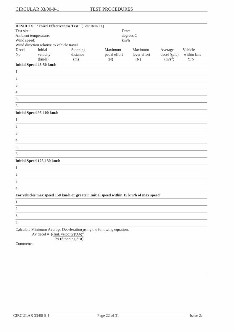
RESULTS: ‘Third Effectiveness Test’ (Test Item 11)Test site : Date:Ambient temperature: degrees CWind speed: km/hWind direction relative to vehicle travelDecel Initial Stopping Maximum Maximum Average VehicleNo. velocity distance pedal effort lever effort decel (calc) within lane
(km/h) (m) (N) (N) (m/s2) Y/NInitial Speed 45-50 km/h
1
2
3
4
5
6
Initial Speed 95-100 km/h
1
2
3
4
5
6
Initial Speed 125-130 km/h
1
2
3
4
For vehicles max speed 150 km/h or greater: Initial speed within 15 km/h of max speed
1
2
3
4
Calculate Minimum Average Deceleration using the following equation:Av decel = ((Init. velocity)/3.6)2
2x (Stopping dist)Comments:
CIRCULAR 33/00-9-1 TEST PROCEDURES
CIRCULAR 33/00-9-1 Page 22 of 31 Issue 2:

6.2.2.12 Test Item 12, ‘Partial Failure’(Clause 33.5.12)This procedure evaluates the braking system forminimum performance under specific component failureconditions. The following areas of failure are to beinduced for each test sequence:- Hydraulic failure First Sub-System- Hydraulic failure Second Sub-System- Inoperative Antilock System- Inoperative Variable Proportioning Brake SystemTest Conditions:Application mode = All service brakesInitial velocity = (i) 45-50 km/h
(ii) 95-100 km/hBrake pedal effort = 40-405 NBrake lever effort = 20-250 NAmbient temperature = 0-40 degrees CWind component = not to exceed 15 km/h
opposing direction of vehicletravel
Acceptance criteria:Minimum averagedeceleration = 3.0 m/s2 (each initial
velocity)
Procedure:- Measure and record ambient temperature, wind speedand wind direction.- Induce one only system/sub-system failure asdescribed in vehicle preparation (Section 6.2.1.2).- Accelerate the vehicle to a speed in excess of therequired initial velocity.- Coast down to the required initial speed andcommence deceleration.- Modulate the brake control efforts to achievemaximum retardation whilst monitoring the display toensure that the required limits are not exceeded.- Determine initial velocity, stopping distance,maximum pedal effort, maximum lever effort and recordon the test data sheets.- Calculate the minimum average deceleration.- Repeat test sequence as required but not exceeding atotal of six attempts.- Restore the brake system to normal condition.- Repeat this procedure for each initial velocity andapplicable mode of failure.During this test sequence record no less information thanthat shown on the following sample data sheet.
RESULTS: ‘Partial Failure’ (Test Item 12)Test site : Date:Ambient temperature: degrees CWind speed: km/hWind direction relative to vehicle travelDecel Initial Stopping Maximum Maximum Average VehicleNo. velocity distance pedal effort lever effort decel (calc) within lane
(km/h) (m) (N) (N) (m/s2) Y/NInitial Speed 45-50 km/h
FIRST SUB-SYSTEM FAILURE1
4
SECOND SUB-SYSTEM FAILURE1
4
INOPERATIVE ANTILOCK SYSTEM1
4
PROPORTIONING SYSTEM FAILURE1
4
Calculate Minimum Average Deceleration using the following equation:Av decel = ((Init. velocity)/3.6)2
2x (Stopping dist)
TEST PROCEDURES CIRCULAR 33/00-9-1
Issue 2: Page 23 of 31 CIRCULAR 33/00-9-1
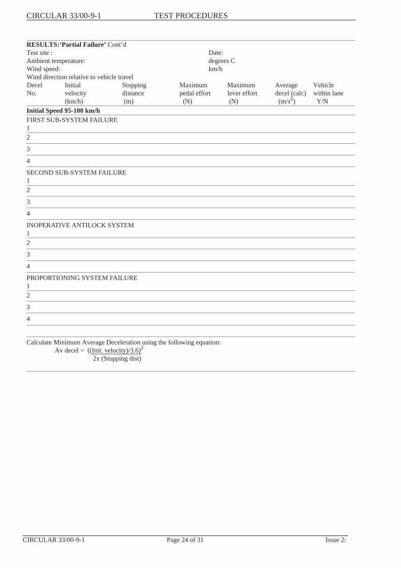
RESULTS:‘Partial Failure’ Cont’dTest site : Date:Ambient temperature: degrees CWind speed: km/hWind direction relative to vehicle travelDecel Initial Stopping Maximum Maximum Average VehicleNo. velocity distance pedal effort lever effort decel (calc) within lane
(km/h) (m) (N) (N) (m/s2) Y/NInitial Speed 95-100 km/hFIRST SUB-SYSTEM FAILURE12
3
4
SECOND SUB-SYSTEM FAILURE12
3
4
INOPERATIVE ANTILOCK SYSTEM12
3
4
PROPORTIONING SYSTEM FAILURE12
3
4
Calculate Minimum Average Deceleration using the following equation:Av decel = ((Init. velocity)/3.6)2
2x (Stopping dist)
CIRCULAR 33/00-9-1 TEST PROCEDURES
CIRCULAR 33/00-9-1 Page 24 of 31 Issue 2:
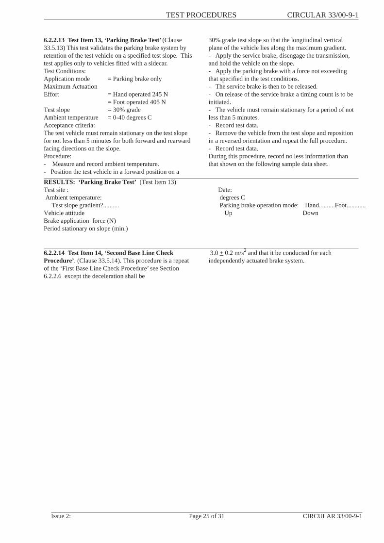
6.2.2.13 Test Item 13, ‘Parking Brake Test’(Clause33.5.13) This test validates the parking brake system byretention of the test vehicle on a specified test slope. Thistest applies only to vehicles fitted with a sidecar.Test Conditions:Application mode = Parking brake onlyMaximum ActuationEffort = Hand operated 245 N
= Foot operated 405 NTest slope = 30% gradeAmbient temperature = 0-40 degrees CAcceptance criteria:The test vehicle must remain stationary on the test slopefor not less than 5 minutes for both forward and rearwardfacing directions on the slope.Procedure:- Measure and record ambient temperature.- Position the test vehicle in a forward position on a
30% grade test slope so that the longitudinal verticalplane of the vehicle lies along the maximum gradient.- Apply the service brake, disengage the transmission,and hold the vehicle on the slope.- Apply the parking brake with a force not exceedingthat specified in the test conditions.- The service brake is then to be released.- On release of the service brake a timing count is to beinitiated.- The vehicle must remain stationary for a period of notless than 5 minutes.- Record test data.- Remove the vehicle from the test slope and repositionin a reversed orientation and repeat the full procedure.- Record test data.During this procedure, record no less information thanthat shown on the following sample data sheet.
RESULTS: ‘Parking Brake Test’ (Test Item 13)Test site : Date:Ambient temperature: degrees C
Test slope gradient?.......... Parking brake operation mode: Hand..........Foot............Vehicle attitude Up DownBrake application force (N)Period stationary on slope (min.)
6.2.2.14 Test Item 14, ‘Second Base Line CheckProcedure’. (Clause 33.5.14). This procedure is a repeatof the ‘First Base Line Check Procedure’ see Section6.2.2.6 except the deceleration shall be
3.0+ 0.2 m/s2 and that it be conducted for eachindependently actuated brake system.
TEST PROCEDURES CIRCULAR 33/00-9-1
Issue 2: Page 25 of 31 CIRCULAR 33/00-9-1

6.2.2.15 Test Item 15, ‘Test of Brakes Subject toWetting’. (Clause 33.5.15) This test evaluates brakeperformance when the brake system friction surfaces aresubject to wet conditions.Test Conditions:Application mode = Each independently actuated system.Minimum conditioning = 1 km.distanceInitial velocity = 45-50 km/h.Maximum pedal effort = As determined in Test Item 14.Maximum lever effort = As determined in Test Item 14.Ambient temperature = 0-40 degrees C.Wind speed = not to exceed 15 km/h
opposing direction of travelNumber of stops = Three.
Acceptance criteria:Average deceleration = not less than 60% or more than120% of the average
deceleration obtained inTest Item 14.
Procedure:
- Measure and record ambient temperature, wind speedand wind direction. Activate the brake wettingequipment.- Accelerate the vehicle to a speed in excess of therequired initial velocity and maintain for not less than 1km.- Coast down to required initial velocity and commencedeceleration.- Modulate the brake effort to achieve the control forcedetermined in Test Item 14. The force is to be achievedwithin 0.5 seconds and maintained for not less than 1.0seconds.- Determine and record the sustained deceleration, initialvelocity and control force.- Repeat test sequence to a total of three decelerations.- On completion of the test attach the chart recording tothe data sheet.During this procedure record no less information thanthat shown on the following sample data sheet.
RESULTS: ‘Test of Brakes Subject to Wetting’ (Test Item 15)Test site : Date:Ambient temperature: degrees CWind speed: km/hWind direction relative to forward direction of test track: ................ degreesBrake system tested:Decel Initial Control SustainedNo. velocity force deceleration
(mis) (N) (m/s2)Initial Speed 45-50 km/h
1
2
3
Average deceleration of 3 runs: ...................(m/s2)Comments:
CIRCULAR 33/00-9-1 TEST PROCEDURES
CIRCULAR 33/00-9-1 Page 26 of 31 Issue 2:

6.2.3 Determination of ResultsResults are determined directly from the test datasheets and no computation is required.All original data that is used for determiningresults is to be retained as either part of the TestingFacility’s internal report, or in a separate originaldata file.6.2.4 Reporting of ResultsFor these tests a complete internal report giving afull description of the material tested, equipmentused, results and order of accuracy, is to beprepared. For submission to the the reportnumber(s) for the above test(s) is to be entered inthe appropriate section of the Summary ofEvidence Report - see Section 8.
7 ANALYSIS OF RESULTS
A vehicle shall be deemed to meet the range ofperformance tests if it meets the requirements of eachparticular test and completes the range of tests withoutcomponent failure and following correction forinstrument accuracy.For the purpose of this Rule, “component failure” means:
- detachment of brake linings from the shoes orpads;- detachment or fracture of any components of thebrake system; or- visible evidence of leakage of brake fluid orlubricant at any wheel cylinder, master cylinderreservoir, cover, seal or retention device, or atfluid line junctions.
The vehicle is deemed to meet the technical requirements
of ADR 33/00 if the results achieved satisfy theacceptance criteria, as detailed in each test item,
8 SUMMARY OF EVIDENCE REPORT
The Summary of Evidence Report SE 33/00 is the onlydocument to be sent to the Administrator fordemonstration of compliance to ADR 33/00. The originaltest report identification number, the location of the testreport, the test facility identification number and thedetermined results are to be recorded in the appropriateplace in the SE 33/00 form for each relevant clause of theADR.
9 PROCEDURE FOR DESIGNS WITHCERTIFICATION TO ALTERNATIVE STANDARDS
There are no Alternative standards for ADR 33/00
10 REFERENCES
ADR ReferencesADR DefinitionsADR 33/00 - Brake Systems for Motor Cycles andMopedsCircularsCircular 0-12-2 - General Requirements for Test FacilitiesCircular 0-12-3 - General Requirements for Calibrationof Test Equipment and InstrumentationCircular 33-2-1 - Demonstration of compliance withPerformance RequirementsCircular 33-3-1 - InterpretationsCircular 33-2-2 - Selection of Test Vehicles
TEST PROCEDURES CIRCULAR 33/00-9-1
Issue 2: Page 27 of 31 CIRCULAR 33/00-9-1

ANNEX A
TEST EQUIPMENT DIAGRAMS
CIRCULAR 33/00-9-1 TEST PROCEDURES
CIRCULAR 33/00-9-1 Page 28 of 31 Issue 2:

ANNEX B
BRAKE EFFORT TRANSDUCER MOUNTING
TEST PROCEDURES CIRCULAR 33/00-9-1
Issue 2: Page 29 of 31 CIRCULAR 33/00-9-1

ANNEX C
Figure 1 Apparatus for Wetting Brakes
CIRCULAR 33/00-9-1 TEST PROCEDURES
CIRCULAR 33/00-9-1 Page 30 of 31 Issue 2:
ANNEX C
DESCRIPTION OF APPARATUS FOR WETTING BRAKES (Clause 33.5.15)
33.5.15.2The test equipment shall continuously wet the brakes foreach test run at a flow rate of 15 litres/hour for each brake.Two disc brakes on one wheel will be considered as 2brakes.33.5.15.3For exposed or partly exposed disc brakes the prescribedamount of water shall be directed onto the rotating disc insuch a manner that it is equally distributed on the surfaceor surfaces of the disc swept by the friction pad or pads.33.5.15.3.1For fully exposed disc brakes the water shall be directedonto the surfaces(s) of the disc one quarter of a revolutionin advance of the friction pad(s).33.5.15.3.2For partly exposed disc brakes the water shall be directedonto the surface(s) of the disc one quarter of a revolutionin advance of the shield or baffle.33.5.15.3.3The water shall be directed onto the surface(s) of thedisc(s) in a continuous jet, in a direction perpendicular tothe surface of the disc, from single jet nozzles sopositioned as to be between the inner extremity and apoint two-thirds of the distance from the outer extremityof that part of the disc swept by the friction pad(s) (seeFigure 1).33.5.15.4For fully enclosed disc brakes the water shall be directedonto both sides of the shield or baffle at a point in amanner corresponding with that described in Clauses33.5.15.3.1 and 33.5.15.3.3. Where the nozzle would be
coincident with a ventilation or inspection port, the watershall be applied one-quarter of a revolution in advance ofthe said port.33.5.15.5Where in the preceding Clauses 33.5.15.3 and 33.5.15.4 itis not possible to apply the water in the position specifiedowing to the presence of some fixed part of the vehicle,the water shall be applied at the first point, exceedingone-quarter of a revolution, where uninterruptedapplication is possible.33.5.15.6To ensure correct wetting of the brakes, the vehicle shallbe driven with the wetting equipment operating for adistance of not less than 1.0 km at the test initial vehiclespeed prior to the application of the brakes being tested.33.5.15.7For drum brakes the prescribed amount of water shall bedistributed equally on either side of the braking device(that is, on the stationary back plate and the rotatingdrum) from nozzles so positioned as to be two-thirds ofthe distance from the outer circumference of the rotatingdrum to the wheel hub.33.5.15.8Subject to the requirements of Clause 33.5.15.7 and tothe requirement that no nozzle shall be within 15° of orcoincident with a ventilation or inspection port on thestationary back plate, the test equipment for drum brakesshall be so positioned as to obtain the optimumuninterrupted application of water.
TEST PROCEDURES CIRCULAR 33/00-9-1
Issue 2: Page 31 of 31 CIRCULAR 33/00-9-1