circuit protection & control products overview
TRANSCRIPT

Circuit Protection & Control, East Asia
Circuit Protection & Control Products Overview

NZM MCCBPage 7-9
LZM MCCBPage 10-13
Circuit Protection &
Control Products
Overview
Low Voltage Circuit Protection
Air Circuit Breakers (ACB) Molded Case Circuit Breaker (MCCB)
IZMX ACBPage 4-6
BZM MCCBPage 14-17
Miniature Circuit Breakers (MCB) Residual Current Device (RCD)
FAZ MCBPLS6 &PLSM MCBPage 18-19 Page 20-21
IsolatorsPage 22-23
PFIM RCDPage 24-25
Surge Protection Devices (SPD)
SPI SeriesPage 26-27
SPB/SPC/SPD/SPE SeriesPage 28-29
NSP SeriesPage 30-31
DG 1 General Purpose Drive
Page 76-79
M-Max Adjustable Frequency AC Drive
Page 80-81
DE1 Variable Speed DrivePage 82-83
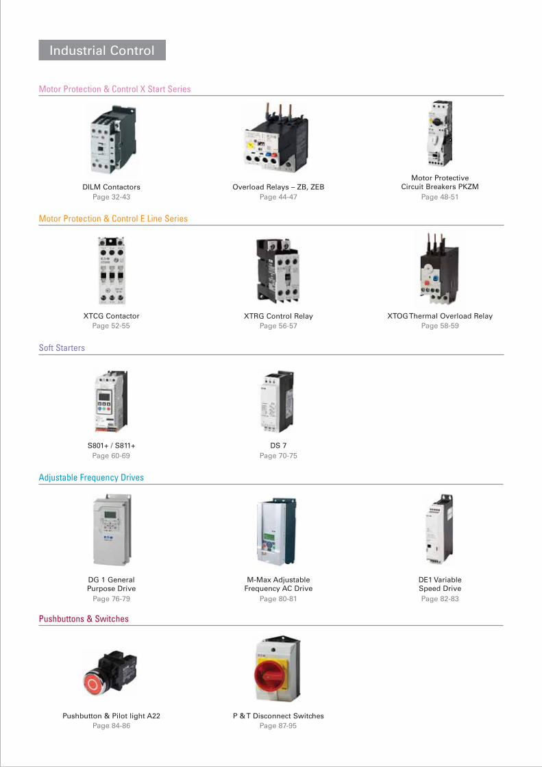
Motor Protection & Control X Start Series
Industrial Control
DILM ContactorsPage 32-43
Overload Relays – ZB, ZEBPage 44-47
Motor Protective Circuit Breakers PKZM
Page 48-51
Motor Protection & Control E Line Series
XTCG ContactorPage 52-55
XTRG Control RelayPage 56-57
XTOG Thermal Overload RelayPage 58-59
Soft Starters
S801+ / S811+Page 60-69
DS 7Page 70-75
Pushbuttons & Switches
Pushbutton & Pilot light A22Page 84-86
P & T Disconnect SwitchesPage 87-95
Adjustable Frequency Drives

4
Air Circuit Breakers IZMX Series
Versatile circuit breakers
up to 4000 A – for cost-effective,
optimized solutions.
The IZMX16 of the NRX series is the smallest air cir-cuit-breaker (ACB) worldwide:With a volume of only 0.024 m³ and a front surface of only 0.092 m², it is just slightly bigger than the size of a A4 sheet of paper! And all this without any loss in terms of performance.
The innovative concept allows the user to install two cir-
cuit breakers side by side in withdrawable design, in a
600 mm wide section. This
The IZMX40 of the NRX series is a circuit breaker for up to 4000 A with depth less than 400mm for the drawout version, without the need to install any additional “copper mines” in the connection area.
Tests to integrate it into Eaton switchgear systems, such as Modan, xEnergy, Power Xpert and Capitol 40 confirm its outstanding tech-nical data and optimal com-patibility thanks to the flexible connection system.
fact provides for a more cost-effective setup of the section and, in addition, it helps to save operating space. And where remote switching is required, this volume can even accommodate a motor for charging the stored-energy spring mechanism and releases for electrical operation. High performance combined with reduced space is exceptional value to customer.
The modular structure, inte-grated solutions as well as a complete range of acces-sories and additional func-tions make it easy to adapt the circuit breaker to any of the required applications. Optionally it can be con-figured right at the factory – without any extra cost for additional installation work at the circuit breaker.
Horizontal Terminal Vertical Terminal(Available on B, N and H type. E type can be configured as horizontal terminal only)

5
Air Circuit Breakers IZMX Series

6
Air Circuit Breakers IZMX Series
Rated Current (In)
Type of circuit breakerRated impulse withstand voltage (Uimp , VAC)Rated insulation voltage (Ui , VAC)Rated operational voltage (Ue , VAC)Ultimate breaking capacity (Icu , kA) 240V 50/60Hz
480V 50/60Hz690V 50/60Hz
Rated service breaking capacity (Ics , kA) 240V 50/60Hz480V 50/60Hz690V 50/60Hz
Rated short-time withstand current (Icw , kA) 1sRated short-circuit making capacity (Icm , kA) 480V 50/60Hz
690V 50/60HzLifespan
Mechanical, w/o maintenance
Mechanical, w/ maintenance
Electrical, w/o maintenance
Dimensions (H × W × D, mm) Fixed 3PFixed 4PWithdrawable 3PWithdrawable 4P
Weight (kg) Fixed 3P/4PWithdrawable 3P/4P
IZMX16 IZMX40630A, 800A, 1000A, 1250A, 1600A 800A, 1000A, 1250A, 1600A, 2000A, 2500A,
3200A, 4000A (E type:800A~2000A only )B N H B N H12000 120001000 1000690
120001000690
120001000690 690
120001000690
120001000690
42 85 85 66 85 10542 50 66 66 85 10542 42 42 66 75 7542 50 65 66 85 10542 50 50 66 85 10542 42 42 66 75 7542 42 42 66 85 1) 85 1)
88 105 145 145 187 23188 88 88 145 165 165
E1200010004806666
6666
66145
630A-1600A 800A-1600A 2000A 2500A-4000A12500 12500 10000 10000
25000 25000 20000 20000
10000 10000 8000 2) 6000 3)
338 × 210 × 184 398 × 376 × 298338 × 279 × 184 398 × 492 × 298360 × 254 × 289 456 × 426 × 393360 × 324 × 289 456 × 541 × 39315/20 45/5639/47 98/121
Technical data

7
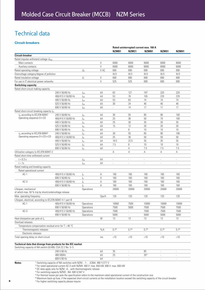
Molded Case Circuit Breaker (MCCB) NZM Series
Switching, Protection, Communication – Compact NZM Circuit Breakers and
Switch-Disconnectors up to 1600 A
The NZM1-4 Molded Case Circuit Breakers range from 25A to 1600 A and incor-
porate four switches with performance overlaps. These are available from 25
kA for small distribution boards up to 150 kA for complex high-energy systems.
Switch-disconnectors up to 1600 A are available in the same design with the
same system accessories.
Compact structure, with four frame sizes up to 1600A.•
Switching capacities up to 150 kA and operational voltages up to 690 V can be • managed without difficulty.
Extensive range of accessories for various installation options.•
Several optional installation modes are available.•
Worldwide approvals available including IEC, UL/CSA and CCC.•
Innovative switching technology with a double-break contact system reduces clear-• ing time. In the event of a short circuit, the special shape and materials selected produce a repelling magnetic force that pushes the contacts apart in a fraction of a cycle.
Available on-board diagnostics software NZM-XPC-SOFT with data logging capabil-• ity allows you to monitor critical circuits without additional hardware.
Discrete relay outputs available for high load warnings at 70%, 100% and 120%.•
Circuit-breakers NZM
8
Molded Case Circuit Breaker (MCCB) NZM Series
Technical data

9
Molded Case Circuit Breaker (MCCB) NZM Series

10
Circuit-breakers LZMCircuit-breakers LZM1, 2, 3, 4 up to 1600 A
Reliably and safely controlling, switching and managing power, in indus-
try, in buildings and in machine construction. Enabled by innovative
protection concepts. Eaton’s LZM Series MCCB is an optimized range of
power distribution circuit breakers designed for general purpose applica-
tions up to 1600A. LZM offers flexible protection options for low voltage
power systems and small machines, including main power distribution
boards with up to 1000V insulation voltage. The LZM is optimized in 4
frame sizes with breaking capacity from 25kA up to 70kA and basic pro-
tective functions for cable and system protection. All trip units include
adjustable short circuit and overcurrent protection.
Circuit-breaker series LZM1 to LZM4
Compact and powerful, the LZM provides several protective functions for general • applications.
The breaking capacity is 25kA - 70kA and the rated current range is 20A - 1600A, • which can meet the requirement for most applications.
With breaking capacity of 25kA - 70kA, electronic and thermal release options • and ratings up to 1600A, LZM meets the requirement for most applications.
Full range of accessories available including various terminals, withdrawable and • plug in units, mechanical interlocking for main devices and handle mechanisms.
Meets applicable IEC 60947-2 Standards with CE mark and CCC approval.•
Flexible mounting using modular function groups•
Full rated current at 50C ambient temperature•
Just 4 compact frame sizes•
Available as 3 and 4-pole device•
Molded Case Circuit Breaker (MCCB) LZM Series

11
Molded Case Circuit Breaker (MCCB) LZM Series

12
Molded Case Circuit Breaker (MCCB) LZM Series
Technical data

13
Molded Case Circuit Breaker (MCCB) LZM Series

14
Molded Case Circuit Breaker (MCCB) BZM Series
Circuit-breakers BZMCompact, simple, safe – BZM1/2/3 circuit breakers
Product description
The BZM molded case circuit breakers series is especially designed for low voltage applications in power distri-bution systems, which have basic technical and economic feature requirements.
The advantage of the BZM series is its simple use: The thermal and magnetic release system for over-current and short-circuit protection of your system is already fac-tory set. Along with simple handling of the product and its accessories, Eaton’s BZM offering provides an attractive product assortment.
The BZM1 for up to 125 A, the BZM2 for up to 250 A and the BZM3 for up to 400 A are among the slimmest in their class, thus providing the most efficient use of space.
Compact
Unbeatable when it comes tosaving space: In the range ofcircuit breakers, the BZM1,BZM2and BZM3 are among the slimmest in their class and can therefore use thevaluabledistribution space most efficiently, regardless of whether they are used for energy sub-distribution or as a protection for incoming power in residential or func-tional buildings.
Simple
Easy to handle:For a fast starting are thermal and magnetic tripping values already fixed.
The BZM series is absolutely easy to handle and allows for quick installation when executing your jobs.
Safe
Eaton’s switchgears have aworldwide reputation for being the benchmark in low-voltage power distribution. Eaton’s quality protects peo-ple and assets againstshortcircuits and overload, with the BZM series being designed for the 16 to 400 A range in sub-distribution.
Standards
In complying with the IEC/EN 60947-2 standards and pollution degree III (IEC/EN 60947) we not only ensure the material but also the immaterial values of the BZM circuit breaker series. And with our BZM series, we also show consideration for the environment as these circuit breakers conform to the RoHS directives and can be recycled to a large extent. And last but not least - the stylish outfit of the BZM series in the distinctiveEaton design makes these products attractive not only from a technical but also from an aesthetic point ofview.

15
Molded Case Circuit Breaker (MCCB) BZM Series

16
Technical data
Molded Case Circuit Breaker (MCCB) BZM Series

17
Molded Case Circuit Breaker (MCCB) BZM Series

18
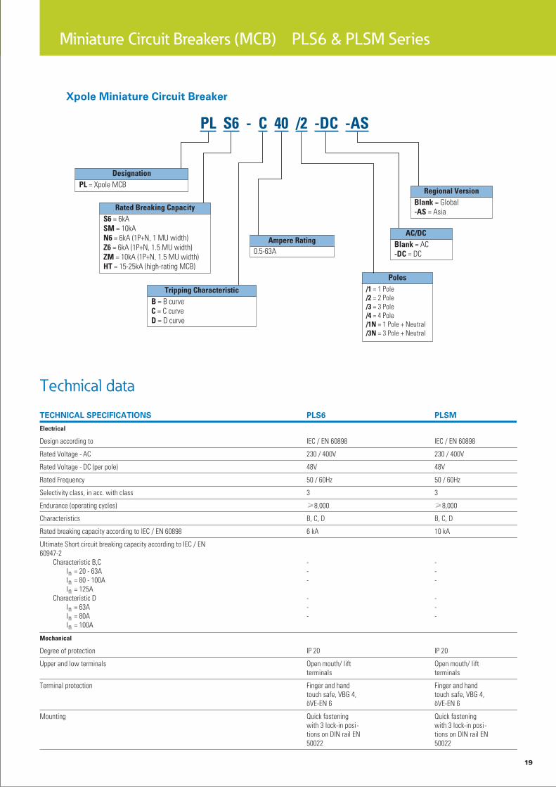
Miniature Circuit Breakers (MCB) PLS6 & PLSM Series
X-Pole series miniature circuit breaker
PLS6 & PLSM
Product description
X-Pole series miniature cir-
cuit breaker overview
Eaton’s X-Pole series min-iature circuit breaker meets the demands of industrial, commercial and residential applications with the wid-est range of offering in the industry. Famous for quality, reliability and colored handles for easy identification, X-Pole series has been the choice of designers, installers and panelbuilders for years. It also offers global ratings like UL for export applications, residual current devices like RCDs and RCBOs for safety and accessories to reduce wiring time.
PLSM miniature circuit
breaker features & benefit
Rated breaking capac-• ity 10kA, PLSM can be widely used in industrial, commercial and residen-tial applications, provid-ing precise overload and short-circuit protection.
Ideal for use as main • switch of indoor circuit protection cabinet with no need for additional switching- disconnec-tor because of its high breaking capacity, saving up to 8% cost
Positive indication of con-• tact position via a clear, easy to identify “red-green” indicator, ensure the personnel safety.
Twin-purpose termi-• nal (lift/open-mouthed above and below allows to install busduct and cables at the same time, reducing wiring time.
3-position DIN rail clip, • permits removal from existing busbar system
Comprehensive range of • accessories suitable for subsequent installation
Meet the latest interna-• tional and national stan-dards: IEC
Rated currents up to 63 • A
Tripping characteristics • (AC): B, C, D
Tripping characteristics • (DC): B, C
PLS6 miniature circuit
breaker features & benefit
High-quality miniature cir-• cuit breakers with rated breaking capacity 6kA, suitable for commercial and residential applica-tions
Ideal for use as main • switch of indoor circuit protection cabinet with no need for additional switching- disconnec-tor because of its high breaking capacity, saving up to 8% cost.
Positive indication of con-• tact position via a clear, easy to identify “red-green” indicator, ensure the personnel safety.
Twin-purpose terminal • (lift/open-mouthed) above and below allows to install busduct and cables at the same time, reducing wiring time.
3-position DIN rail clip, • permits removal from existing busbar system
Comprehensive range of • accessories suitable for subsequent installation
Meet the latest interna-• tional and national stan-dards: IEC
Rated currents up to 63 • A
Tripping characteristics • (AC): B, C, D
Tripping characteristics • (DC): C
19
Miniature Circuit Breakers (MCB) PLS6 & PLSM Series
Technical data
20
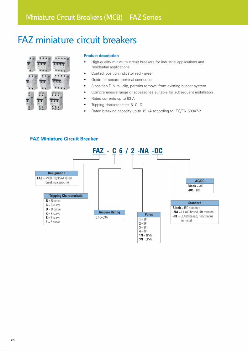
Miniature Circuit Breakers (MCB) FAZ Series
FAZ miniature circuit breakers
Product description
High-quality miniature circuit breakers for industrial applications and• residential applications
Contact position indicator red - green•
Guide for secure terminal connection•
3-position DIN rail clip, permits removal from existing busbar system•
Comprehensive range of accessories suitable for subsequent installation•
Rated currents up to 63 A•
Tripping characteristics B, C, D•
Rated breaking capacity up to 15 kA according to IEC/EN 60947-2•

21
Miniature Circuit Breakers (MCB) FAZ Series
Technical data
22
Miniature Circuit Breakers (MCB) Xpole Series - Isolator
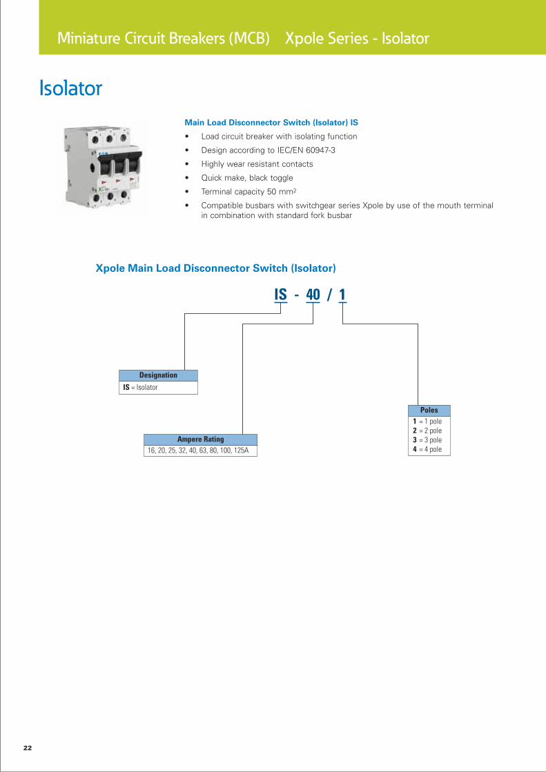
Isolator
Main Load Disconnector Switch (Isolator) IS
Load circuit breaker with isolating function•
Design according to IEC/EN 60947-3•
Highly wear resistant contacts•
Quick make, black toggle•
Terminal capacity 50 mm• 2
Compatible busbars with switchgear series Xpole by use of the mouth terminal • in combination with standard fork busbar
23
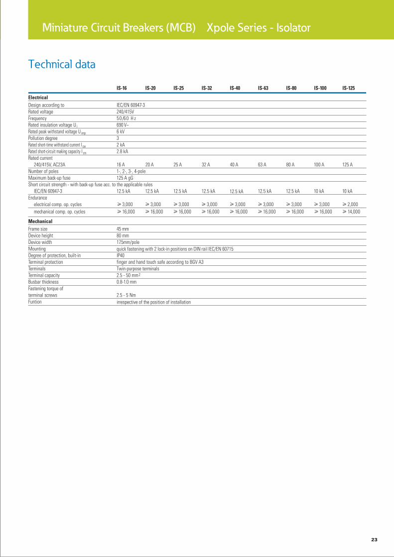
Miniature Circuit Breakers (MCB) Xpole Series - Isolator
Technical data
24
Residual Current Device (RCD) Xpole Series - PFIM
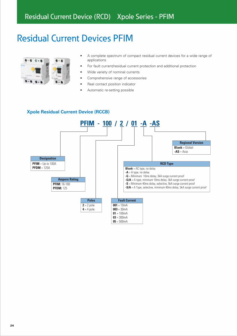
Residual Current Devices PFIM
A complete spectrum of compact residual current devices for a wide range of • applications
For fault current/residual current protection and additional protection•
Wide variety of nominal currents•
Comprehensive range of accessories•
Real contact position indicator•
Automatic re-setting possible •

25
Residual Current Device (RCD) Xpole Series - PFIM
Technical data

26
SPD Class B, Lightning Current Arrester SPI
Field of application: For the protection of low voltage distribution systems against • direct lightning stroke into the overhead power supply line or external lightning pro-tection system (IEC 62305).
Application according to IEC 60364-5-53 Clause 534•
Test class in accordance with IEC 61643-1•
SPD-type in accordance with EN 61643-1•
Capsuled version: during the discharge process, the device does not issue any hot • ionised gases. Therefore, there is no need for keeping a safety distance to flam-mable materials.
Practical Hint
Installation of lightning current arresters upstream of the meter is subject to co-ordina-tion with the relevant power supply company.
Installation of an r.m.s.ective protection cascade (SPD classes B, C, D) requires co-ordi-nated application of the respective protective devices. This is ensured by a defined line length between protective devices. When using lightning current arresters of type SPI in connection with surge arresters SPC with a maximum continuous operating voltage Uc of 460 V AC, no specific line length or decoupling coils are required.
I
T1
Surge Protection Devices (SPD) SPI Series
27
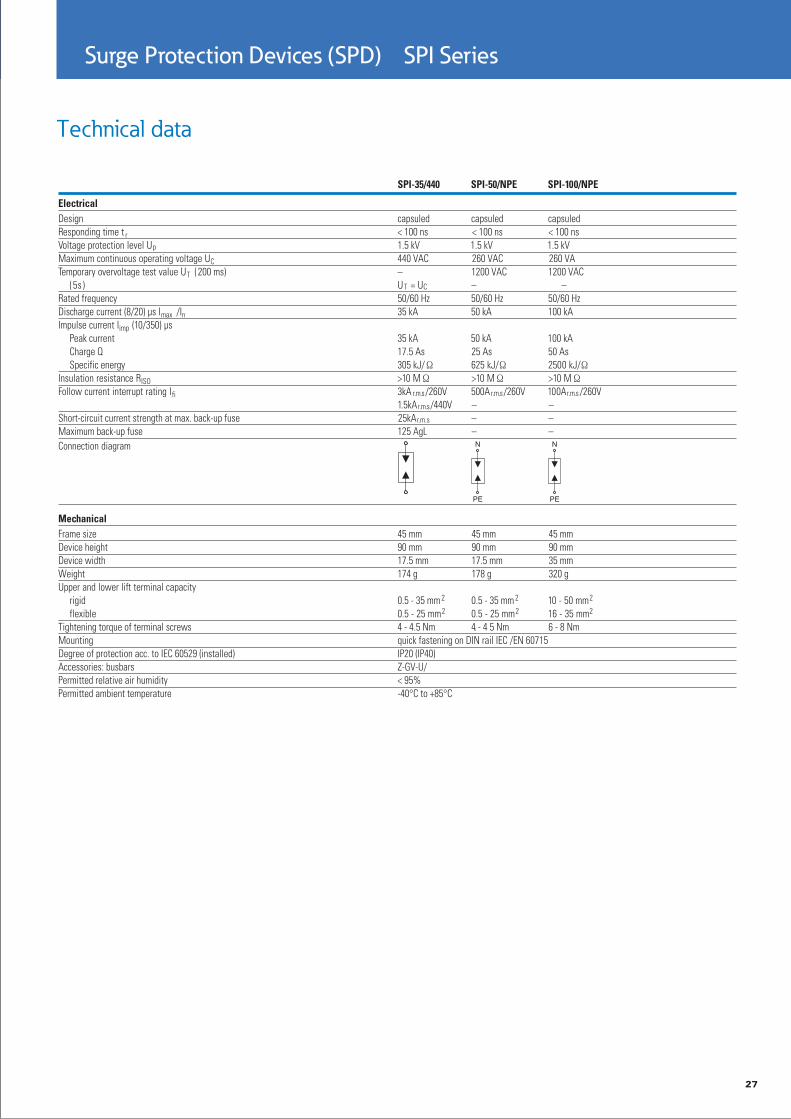
Surge Protection Devices (SPD) SPI Series
Technical data

28
Surge Protection Devices (SPD) SPB/SPC/SPD/SPE Series
SPB/SPC/SPD/SPE
Product description:
A complete SPD range covers all B,C and D (that is I,II,and III) protection degrees, pro-viding your expensive and sensitive electrical equipment with safe lightning protec-tion or surge voltage impulse caused by medium and large switch operations in your cir-cuit, such as large computer center, digital and IT system equipment, precise electronic instrument and family HIFI equipment.
Features:
Field of application: • For the protection of low voltage distribution systems against direct lightning strike into the overhead power supply line or external lightning protection system (IEC 62305)
Application according to • IEC 60364-5-53 Clause 534
Test class I, II, III in • accordance with IEC 61643-1
SPD-type T1, T2, resp. T3 • in accordance with EN 61643-1
Lightning protection • classes III and IV in accordance with IEC 62305
Capsuled version: during • the discharge process, the device does not issue any hot ionised gases. Therefore, there is no need for maintaining a safety distance from flammable materials.
Depending on application • available in single, pre-as-sembled with busbar, or preconfigured for most applications and power grids

29
Surge Protection Devices (SPD) SPB/SPC/SPD/SPE Series
Technical data

30
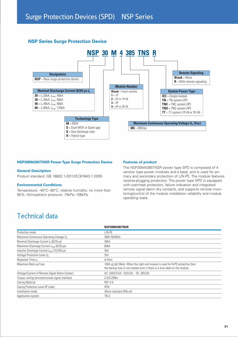
Surge Protection Devices (SPD) NSP Series
NSP Series High-performance Lightning and
Surge Protection Products
The NSP series of surgeprotection devices is a newoptimized series from Eaton,covering correspondingprotection levels B and C (i.e., I and II). It protects your expensive and sensitive elec-tronic and electrical equip-ment, such as large comput-ing centers, digital and IT system equipment andprecision electronic equip-ment, against lightning or surge voltage impulses due to opening and closing of large switches in circuits.
High surge discharge • capacity based on heavy zinc oxide varis-tor and spark gap tech-nology conforming to IEC61643-1 and Chinese standard GB18802.1-2011.
The series is classified • into four sub-series: IEC, wind turbine, photovol-taic, and signal protec-tion. NSP surge protec-tion devices have been optimized for different industries and can cover most application environ-ments.
A new series of signal-• protection SPD is added to protect SCADA sys-tem, field bus, network and videos signal trans-mission systems.
Equipotential bonding • spark gap is developed to ensure a reliable ground-ing connection in case of lightning or surge and can cover applications in petrochemicals and other industries.
In addition to our AC SPD • series, we also provide dedicated 1000VDC products which are espe-ciallyapplicable to solar power systems or other DC loads.
Most of the products in • the NSP series (except signal protection SPD and equipotential bond-ing devices) are equipped with remote signalling (auxiliary contact) indica-tion that transmits surge product status signals to your monitoring and con-trolling room so that you-can know your product’s status without on-site inspection.
IEC surge protection • devices provide maxi-mum discharge current Imax (120, 80, 60, and 40) (8/20)µs to meet the protection needs of vari-ous buildings.
Two parameter options • are offered for Level I SPD protection devices: (10/350)µs and (8/20)µs.
All NSP series products • are among the most cost-effective products available, and multipolar-products are equipped with standard bus bars, making installation quick and easy, and avoiding the need to use long cable connections with excessive residue volt-age due to too.
Compact: The 80 or • 120kA single-pole devic-es in the IEC SPD series are only 36mm wide, and single-pole devices of less than 60kA are only 18mm wide, which greatly saves space in the electrical cabinet.
Clear aging indication • window provides reliable status indication so that you can see the product status without special testing, which greatly facilitates maintenance and replacement.
High-performance flame-• retardant casing mate-rials ensure safe and reliable uses IEC series products have authori-tative third-party test reports, which are on file at the Meteorological Bureaus of major prov-inces (municipalities) in China, for use in building projects.
31
Surge Protection Devices (SPD) NSP Series
NSP30M4385TNSR Power Type Surge Protection Device
General Description
Product standard: GB 18802.1-2011/IEC61643-1:2005.
Environmental Conditions
Temperature: -40°C~80°C; relative humidity: no more than 95%; Atmospheric pressure: 70kPa~106kPa.
Features of product
The NSP30M4385TNSR power type SPD is composed of 4 varistor type power modules and a base, and is used for pri-mary and secondary protection of L/N-PE. The module featuresreverse-plugging protection. The power type SPD is equipped with over-heat protection, failure indication and integrated remote signal alarm dry contacts, and supports remote moni-toring/control of the module installation reliability and module operating state.
Technical data

32
Motor Control & Protection X Start Series
Mini contactor relays, contactor relay, contactors
Continual operation requires high operational reliability in the components used.
The DILM contactor achieves the best lifespan values in AC-3 applications and is
ideal for heavy AC-4 jogging.
Mini contactor relay DILE…,
contactor relays, contactors
up to 12 A AC-3 at 400 V
Compact dimensions for the highest packing densities +++ Extended performance range up to 5.5 kW at 400 V.
AC and DC contactor sys-
tem DILM…, contactor
relays, 3 pole contactors
up to 170 A AC-3 at 400 V, 4
pole contactors up to 200
A AC-1
Easier engineering through identical construction sizes for AC- and DC-operated con-tactors +++ Energy savings and higher packing density in control panel due to mini-mized heat dissipation +++ High wiring security through doubled box terminals +++ Less coupler relays: direct actuation from the PLC for contactors up to 32 A +++ Easy engineering through
integrated suppressor cir-cuits for DC +++ Uniform accessories for 3- and 4-pole contactors +++ Mechanical interlock double conductor run mountable without addi-tional separation gap +++ Direct fieldbus connection through the communication system SmartWire-Darwin, through plug-in type protec-tive module.
High rated contactors - con-
tactors up to 1600 A AC-3 at
400 V, contactors up to 2600
A AC-1
Compact dimensions with high switching power +++ Direct actuation from the PLC saves coupler relays +++ Easy engineering through wide range coils +++ Cost and energy savings for con-trol panel ventilation due to reduced heat dissipation +++ Long lifespan through vacu-um technology from 580 A.
SmartWire-Darwin
The DIL product range offers contact elements which can be connected to the SmartWire-Darwin communi-cation system.

33
6 1 1
3
97
55
4 10
2
86
6 6
11
33
32
554
Motor Control & Protection X Start Series

34
5
4
3
2
1
Motor Control & Protection X Start Series

35
Motor Control & Protection X Start Series

36
Motor Control & Protection X Start Series
Technical data(Basic Devices up to 170A)

37
Motor Control & Protection X Start Series

38
Motor Control & Protection X Start Series

39
Motor Control & Protection X Start Series

40
Motor Control & Protection X Start Series
Technical data(Comfort devices and standard devices greater 170A)

41
Motor Control & Protection X Start Series

42
Motor Control & Protection X Start Series

43
Motor Control & Protection X Start Series

44
Motor Control & Protection X Start Series
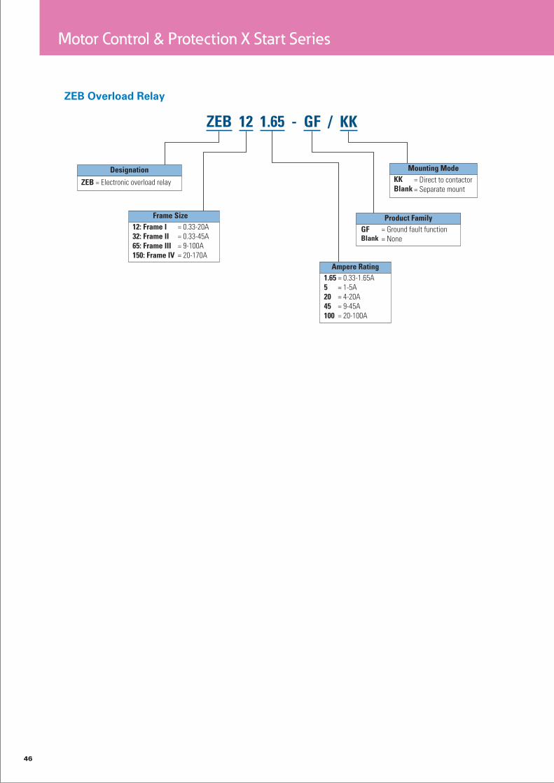
Overload relay
Motor protection is a central task of electrical equipment for machinery.
From cost-effective bimetal solutions to demanding full motor protection
with cross-linkage - we offer the right solution for each application.
Bimetal relay - overload relay up to 630 A
Direct mounting on contactor saves mounting time.•
ATEX approval for the protection of EEx e motors up to 250 A.•
Comprehensive motor protection through phase failure sensitivity.•
Integrated test pushbutton facilitates high safety.•
ZEB electronic overload relay - overload relay up to 1500 A
ATEX approval for protection of EEx e motors up to 1500 A.•
Adjustable tripping classes.•
Phase failure and unbalance protection.•
Optional earth fault detection.•
Additional current setting range (5:1).•
EMT6 thermistor overload relay for machine protection
Overload protection through direct evaluation of winding temperature.•
Quick detection of operating state through LED display.•
Suitable for overload monitoring of motors in EEx e range.•
Wide range power supply reduces amount of types.•

45
Motor Control & Protection X Start Series
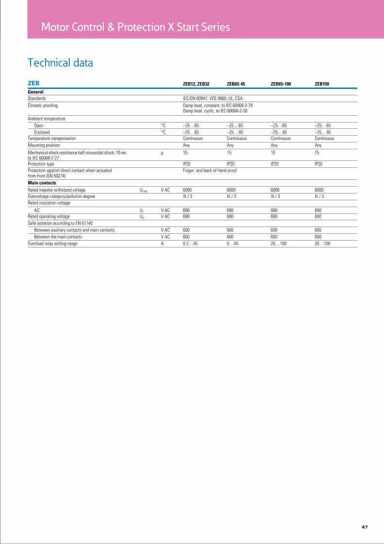
Technical data
See catalogue for more information
See catalogue for more information
46
Motor Control & Protection X Start Series
47
Motor Control & Protection X Start Series
Technical data

48
Motor Control & Protection X Start Series
PKZ and PKE motor-protective
circuit-breakers
Machinery and installation downtimes should be kept as short as possible.
The PKZ fuseless motor-protective circuit-breakers combine short-circuit
and overload protection in one device, allowing fast restart readiness.
PKZM01, PKZM0, PKZM4 and PKE have the same accessories. Combines
easily with DILM contactors and DS7 soft starters. Connecting PKE to
SmartWire-Darwin facilitates high data transparency.
PKZM01 (up to 16) motor-protective circuit-breaker with pushbuttons
Motor-protective circuit-breaker in housing for protection types IP40 and IP65 +++ Integrated EMERGENCY STOP and EMERGENCY OFF pushbuttons reduce wiring.
PKZM0 (up to 32 A) and PKZM4 (up to 65 A) motor-protective circuit-breakers with
rotary handle
Short-circuit proof up to at least 50 kA for easy engineering +++ Trip-indicating auxiliary contact enables remote diagnosis +++ High safety through application as main switch or repair and maintenance switch +++ ATEX approval for protection of EEx e motors up to 65 A PKE (up to 65 A) motor-protective circuit-breakers with electronic wide-range overload protection High flexibility through plug-in trip block +++ Wide current setting ranges enable only five trip blocks up to 65 A +++ Precise and extremely long-term stable characteristic curves +++ Individual supply through integrated current converter +++ ATEX approval for protection of EEx e motors up to 65 A +++ Adjustable tripping classes.
DC string circuit-breakers PKZ-SOL and DC switch-disconnectors P-SOL (up to 63
A) for installations
High string circuit-breaker flexibility due to wide current setting range +++ Enclosed switchdisconnector for external mounting (IP65) +++ Remote shutdown through optional secondary voltage and shunt trip +++ Voltage up to 1000 V DC +++ TÜV certi-fied.

49
Motor Control & Protection X Start Series
18
7 7
6
7
23
7
7
3
45
5

50
Motor Control & Protection X Start Series
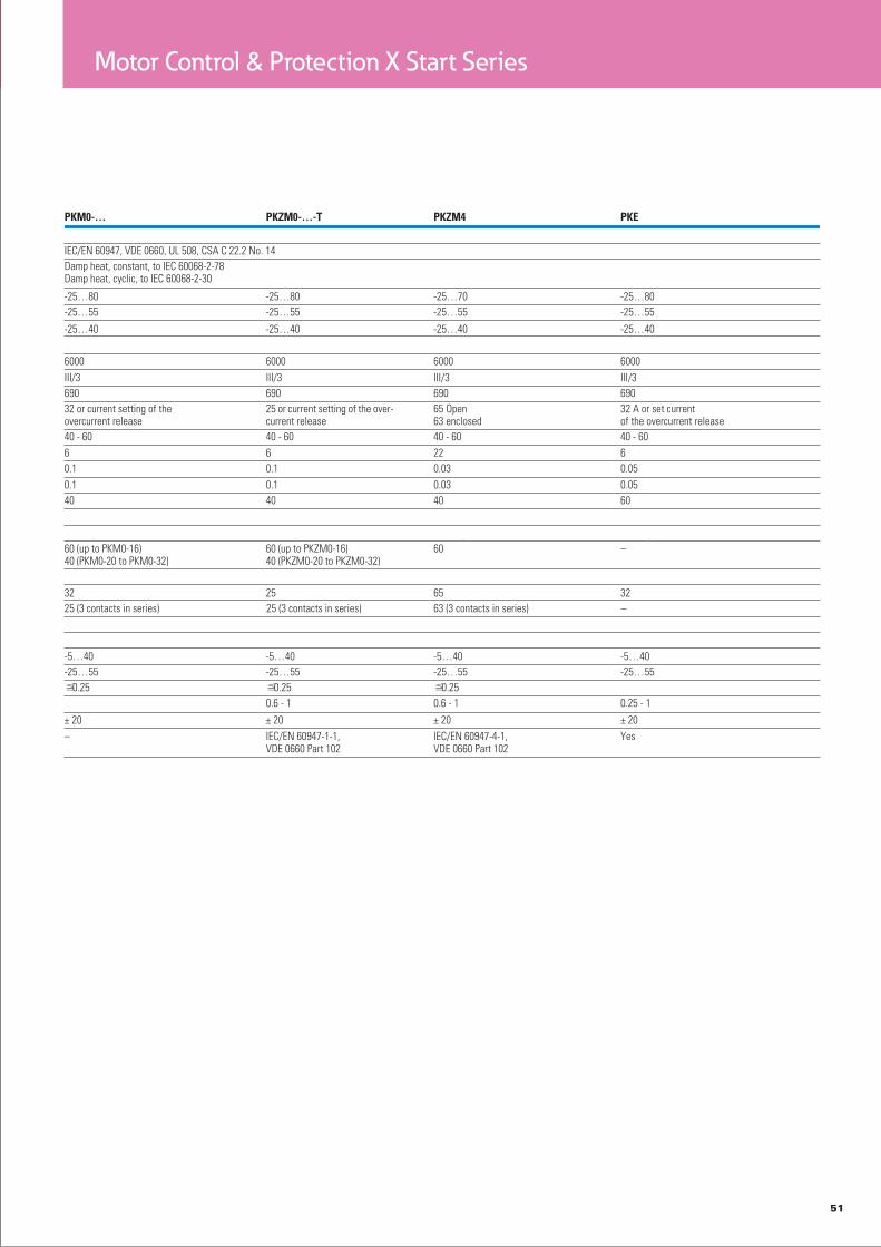
Technical data
51
Motor Control & Protection X Start Series

52
Motor Control & Protection E Line Series
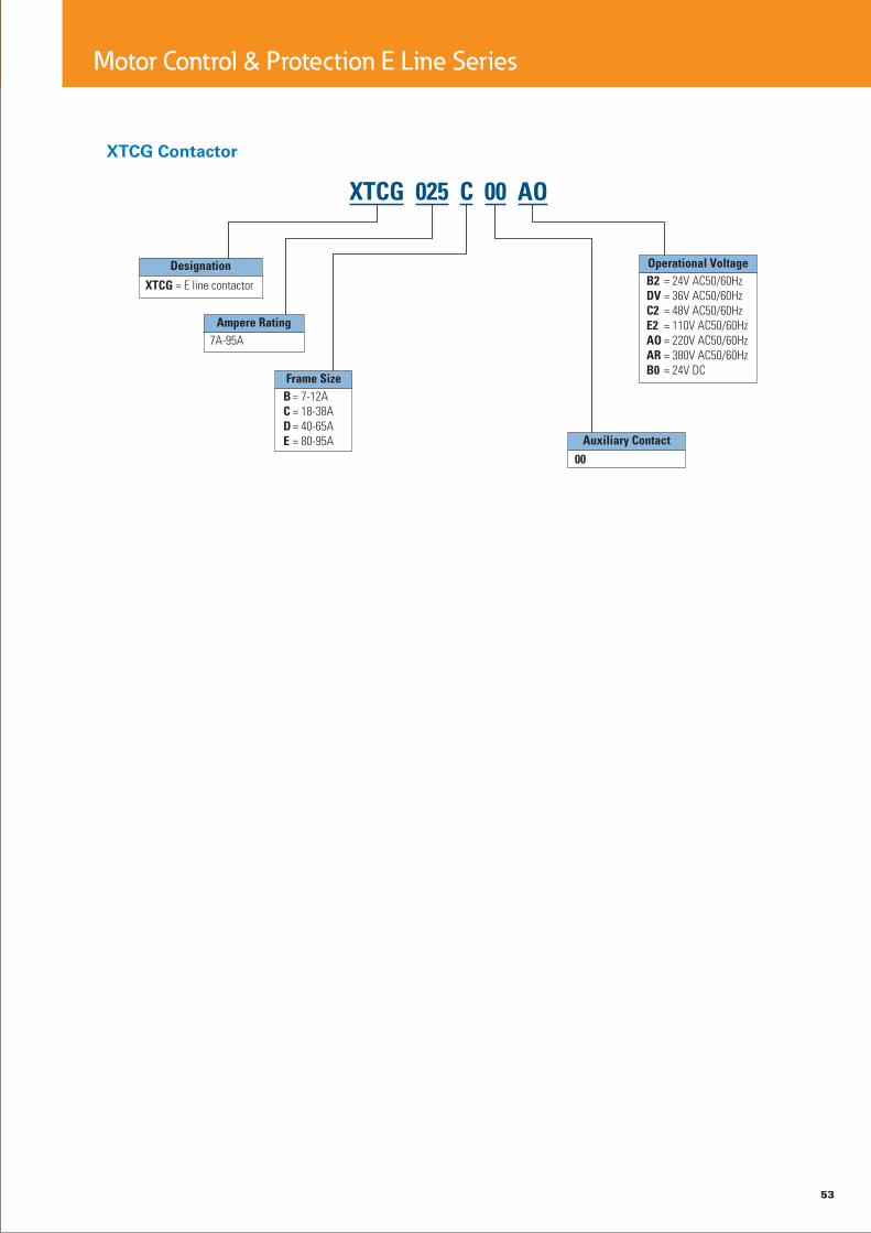
Contactors XTCG
Product description
The XTCG is the flagship of the E Line family of motor controls. The XTCG contac-tor offers space savings, enhanced reliability and more efficient use of materi-als. Boasting AC-3 ratings up to 95A @ 400V and with a maximum operating volt-age of 660V, XTCG offers tremendous performance in a small package.
Features
Technologically advanced • contact design
690V insulation rating•
Operating voltage up to •
660VAC•
Up to (3) add on auxiliary • contact modules
All common AC control • voltages
DIN rail or panel mount • options
Unique space saving • design
System overview
3 phase contactors are used to start motors or control industrial loads. The E Line family of contactors allows the starting of motors up to 45kW, and when combined with an XTOD overload relay or PKZC motor protective cir-cuit breaker offers a complete package of protection and control for long life and reli-able operation.
Standards and certifications
GB 14048•
IEC/EN 60947•
CCC•
CE•
53
Motor Control & Protection E Line Series

54
Technical data
Motor Control & Protection E Line Series

55
Motor Control & Protection E Line Series

56
Motor Control & Protection E Line Series
Control relays XTRG
Product description
Part of the E Line family of controls, the XTRG control relay offers space sav-ings, enhanced reliability and more efficient use of materials. Rated to operate thermal currents up to 10A, AC voltages up to 660V or DC voltages up to 250V, the XTRG contactor relay offers optimum performance in a compact package.
Features
10A Control relay •
690V Insulation rating•
660VAC or 250VDC • Operational voltage
Up to 5 sets of normally • open or normally closed contacts with add-on blocks
All common AC control • voltages
DIN rail or panel mount • options
Unique 27mm design•
System overview
Control relays are used to remotely switch small loads or in complex control schemes. The XTRG relay can be integrated with con-tactors from the E Line ramily of motor controls to create compact, efficient control panels for a multitude of applications.
Standards and certifications
GB 14048•
IEC/EN 60947•
CCC•
CE•

57
Motor Control & Protection E Line Series
Technical data

58
Motor Control & Protection E Line Series
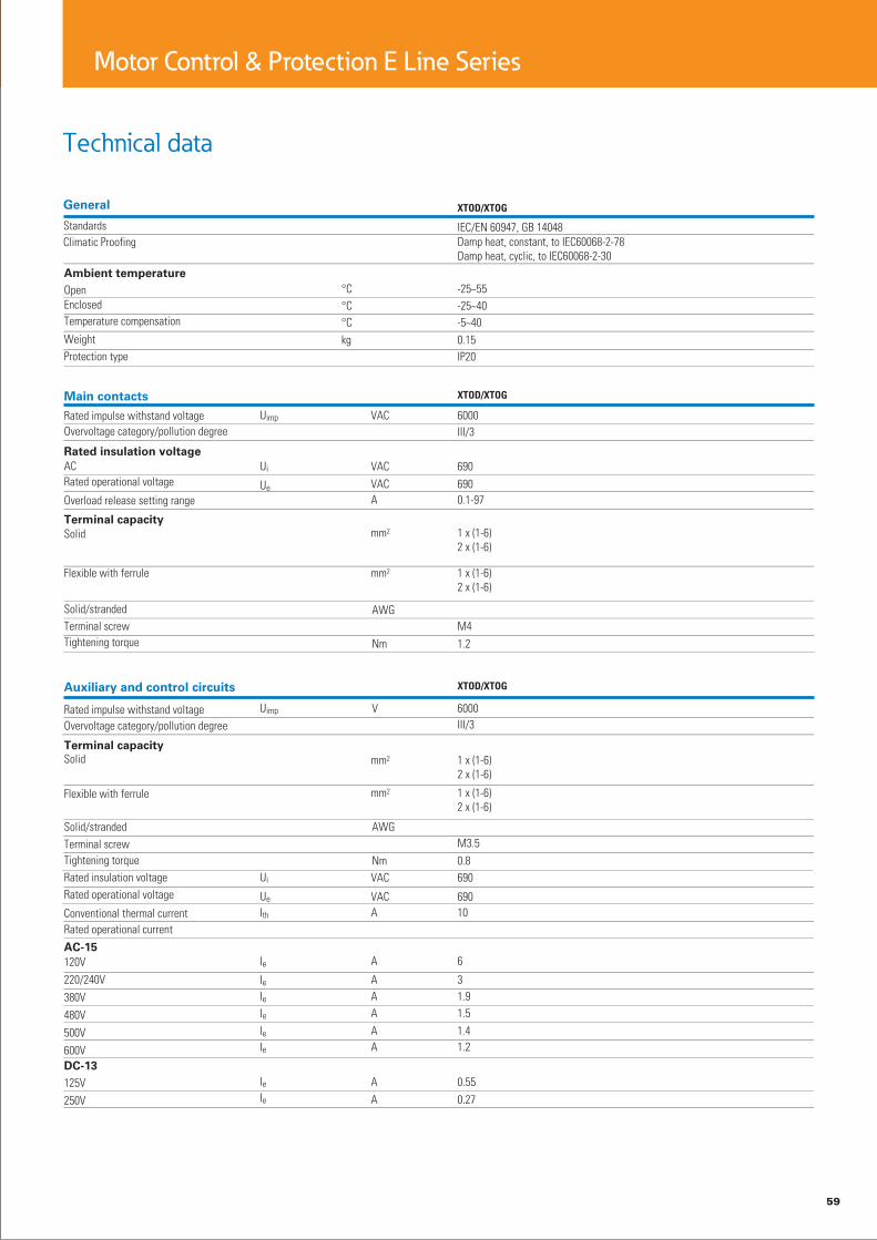
Thermal overload relays XTOD/XTOG
Product description
XTOD/XTOG thermal over-load relays offer precision motor protection with phase loss protection and ambient temperature compensation. The seperate mount design allows for flexibility and the units can be mounted on DIN rail or directly on the panel adjacent the motor contactor.
XTOD... is for separate mounting; XTOG is for direct mounting.
Features
Precision motor protec-• tion up to 97A
Integral 1NO/1NC con-• tact for contactor control and alarm signal
Phase loss protection•
Ambient temperature • compensation
DIN rail or panel mount • options
System overview
Thermal overload relays pro-vide protective features for 1 or 3 phase motors. The relay monitors the operat-ing current of the motor and switched the contactor off in the event of an overload situation. It also protects the motor from damage during phase loss.
Standards and certifications
GB 14048•
IEC/EN 60947•
CCC•
CE•
59
Motor Control & Protection E Line Series
Technical data

60
Soft Starters S801+ & S811+
Soft starter S801+, S811+
S801+ series soft starters are an innovative addition that further enhances their tried-and-true predecessors. They are designed to guarantee reliable operation even under harsh and challenging ambi-ent conditions. In addition,the series makes a compel-ling case as a result of its ease of use and is theperfect choice for standard applications such as pumps, fans, compressors, and con-veyor belts.
S801+ soft starters are three-phase controlled and come with internal bypass contacts for continuous operation. With them, motors can be connected with a standard in-line circuit or inside the delta circuit (inside-the-delta circuit,√3 circuit). Using an inside-the-delta circuit will reduce the current flowing through the soft starter by approxi-mately 42%. This makes it possible, for example, to start and run a motor with a rated operational current of 100 Ausing a 58-A soft starter. In addition, their comprehensive protection and monitoring features enable S801+ soft starters to ensure that three-phase motors with rated operational currents of 11 A to 1000 A will have soft start-ups and safe and reliable con-tinuous operation at mains voltages of 200 V to 600 V– up to 690 V in the case of S811+ soft starters. Accordingly, for instance, their controlled coasting (soft stop control) and torque mon-itoring features can beused to prevent water impact in pumps and to reduce the mechanical loads on pump systems significantly.
S801+ specific characteristics
Microswitches and • potentiometers make it easy to configure these soft starters
S811+ series soft starters provide all the features and characteristics of S801+ soft starters, plus expanded func-tionality and an operating unit(DIM = digital interface mod-ule).
Important operating unit
characteristics (S811+)
Language-neutral LCD • display with backlight
Easy to use and config-• ure with function keys
System parameter con-• figuration
Diagnostic and monitor-• ing options
Reading display (e.g., L1, • L2, L3 phase currents)
Error display•
Offset placement • (mounted on door), con-nection via plug-in patch cord with RJ45 plug
Front IP54•
S811+ specific characteristics
• Mains voltage up to 690 V?• Special pump control algo-rithm with prolonged soft stop ramp
Essential features S801+ /
S811+
Rated operational cur-• rent: 37 - 1000 A
Parameterizable overload • settings: 31–100%
Adjustable overload • classes: class 5, 10, 20, 30
Base setting: 15 s start • ramp, 4 starts per hour, 300% starting current at 40 °C ambient tempera-ture
Allocated motor outputs • for in-line connection: – 7.5 - 277 kW (3~ 230V) – 18.5 - 525 kW (3~ 400 V) – 30 - 900 kW (3~ 690 V)
Ambient air temperature: • -30 °C to +50 °C any required mounting posi-tion
Degree of protection • with compact design (IP20 optional)
5 compact designs•
Adjustable torque control•
Adjustable kick start•
Efficient use of power • achieved with internal bypass contacts during continuous operation
24-V control voltage: • – External supply required – 1 A continuous current – 10 A starting current (peak value for 15 ms)

61
Soft Starters S801+ & S811+
62
Soft Starters S801+ & S811+
Technical data
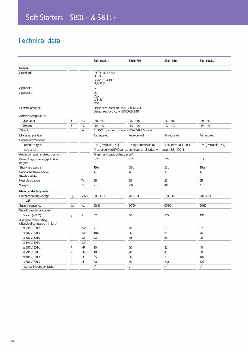
S8x1+N37… S8x1+N66… S8x1+R10… S8x1+R13…
General
Standards IEC/EN 60947-4-2UL 508CSA22.2-14-1995GB14048
Approvals CEApprovals UL
CSAC-TickCCC
Climatic proofing Damp heat, constant, to IEC 60068-2-3Damp heat, cyclic, to IEC 60068-2-10
Ambient temperatureOperation °C -30 - +50 -30 - +50 -30 - +50 -30 - +50Storage °C -50 - +70 -50 - +70 -50 - +70 -50 - +70
Altitude m 0 - 2000 m, above that each 100 m 0.5% DeratingMounting position As required As required As required As requiredDegree of protection
Protection type IP20 (terminals IP00) IP20 (terminals IP00) IP20 (terminals IP00) IP20 (terminals IP00)Integrated Protection type IP40 can be achieved on all sides with covers SS-IP20-N.
Protection against direct contact Finger- and back-of-hand proofOvervoltage category/pollution degree
II/3 II/3 II/3 II/3
Shock resistance 15 g 15 g 15 g 15 gRadio interference level (IEC/EN 55011)
A A A A
Heat dissipation W 25 25 25 25Weight kg 2.6 2.6 4.8 4.8
Main conducting paths
Rated operating voltage Ue V AC 200 - 600 200 - 600 200 - 600 200 - 600…V3S - - - -
Supply frequency fLN Hz 50/60 50/60 50/60 50/60Rated operational current
Device (AC-53) Ie A 37 66 105 135Assigned motor rating (Standard connection, In-Line)
at 230 V, 50 Hz P kW 7.5 18.5 30 37at 400 V, 50 Hz P kW 18.5 30 55 75at 500 V, 50 Hz P kW 22 45 55 90at 690 V, 50 Hz P kW - - - -at 200 V, 60 Hz P HP 10 20 30 40at 230 V, 60 Hz P HP 10 20 40 50at 480 V, 60 Hz P HP 25 50 75 100at 600 V, 60 Hz P HP 30 60 100 125Internal bypass contacts

63
Soft Starters S801+ & S811+
S8x1+T18… S8x1+T24… S8x1+T30… S8x1+U36… S8x1+U42…
IEC/EN 60947-4-2UL 508CSA22.2-14-1995GB14048CE CE CE CE CEULCSAC-TickCCCDamp heat, constant, to IEC 60068-2-3Damp heat, cyclic, to IEC 60068-2-10
-30 - +50 -30 - +50 -30 - +50 -30 - +50 -30 - +50-50 - +70 -50 - +70 -50 - +70 -50 - +70 -50 - +700 - 2000 m, above that each 100 m 0.5% DeratingAs required As required As required As required As required
IP20 (terminals IP00)An IP20 degree of protection can be achieved on all sides by using optional terminal covers SS-IP20-TU.Finger- and back-of-hand proofII/3 II/3 II/3 II/3 II/3
15 g 15 g 15 g 15 g 15 gA A A A A
25 25 25 25 2518.6 18.6 18.6 18.6 18.6
200 - 600 200 - 600 200 - 600 200 - 600 200 - 600200 - 690 200 - 690 200 - 690 - -50/60 50/60 50/60 50/60 50/60
180 240 304 361 420
55 75 90 110 13290 132 160 200 200110 160 200 250 250160 200 250 - -60 75 100 125 12560 75 100 150 150150 200 250 300 350150 200 300 350 450

64
Soft Starters S801+ & S811+
Soft start function
Ramp timesAcceleration s 180 180 180 180Deceleration s 0 - 60 0 - 60 0 - 60 0 - 60
Start pedestal % 85 85 85 85Kickstart
Voltage % 100 100 100 100Duration
50 Hz ms 2000 2000 2000 200060 Hz ms 2000 2000 2000 2000
Fields of applicationFields of application Soft starting of three-phase asynchronous motors3-phase motors
Functions
Fast switching (semiconductor contactor)
- (minimum ramp time 1s)
Soft start functionReversing starter External solution required (reversing contactor)Suppression of closing transientsCurrent limitationOverload monitoringUnderload monitoringFault memory Faults 10 10 10 10Suppression of DC components for motorsPotential isolation between power and control sectionsBuilt-in interfaces Modbus RTU Modbus RTU Modbus RTU Modbus RTU
S8x1+N37… S8x1+N66… S8x1+R10… S8x1+R13…

65
Soft Starters S801+ & S811+
180 180 180 180 1800 - 60 0 - 60 0 - 60 0 - 60 0 - 6085 85 85 85 85
100 100 100 100 100
2000 2000 2000 2000 20002000 2000 2000 2000 2000
Soft starting of three-phase asynchronous motors
- (minimum ramp time 1s)
External solution required (reversing contactor)
10 10 10 10 10
Modbus RTU Modbus RTU Modbus RTU Modbus RTU Modbus RTU
S8x1+T18… S8x1+T24… S8x1+T30… S8x1+U36… S8x1+U42…

66
Soft Starters S801+ & S811+
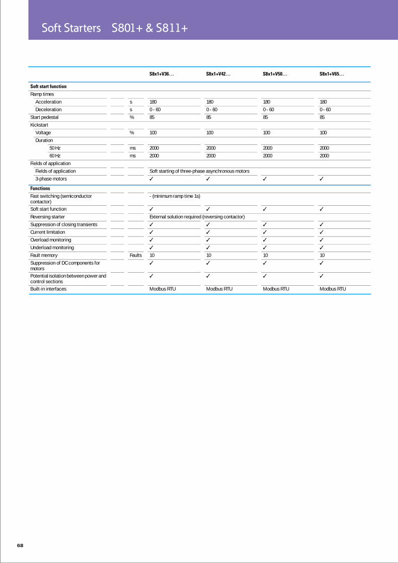
Technical data
S8x1+V36… S8x1+V42… S8x1+V50… S8x1+V65…
General
Standards IEC/EN 60947-4-2UL 508CSA22.2-14-1995GB14048
IEC/EN 60947-4-2UL 508CSA22.2-14-1995GB14048
IEC/EN 60947-4-2UL 508CSA22.2-14-1995GB14048
IEC/EN 60947-4-2UL 508CSA22.2-14-1995GB14048
Approvals CE CE CE CEApprovals UL
CSAC-TickCCC
ULCSAC-TickCCC
ULCSAC-TickCCC
ULCSAC-TickCCC
Climatic proofing Damp heat, constant, to IEC 60068-2-3Damp heat, cyclic, to IEC 60068-2-10
Ambient temperatureOperation °C -30 - +50 -30 - +50 -30 - +50 -30 - +50Storage °C -50 - +70 -50 - +70 -50 - +70 -50 - +70
Altitude m 0 - 2000 m, above that each 100 m 0.5% DeratingMounting position As required As required As required As requiredDegree of protection
Protection type IP20 (terminals IP00) IP20 (terminals IP00) IP20 (terminals IP00) IP20 (terminals IP00)Integrated Protection type IP40 can be achieved on all sides with covers SS-IP20-N.
Protection against direct contact Finger- and back-of-hand proofOvervoltage category/pollution degree
II/3 II/3 II/3 II/3
Shock resistance 15 g 15 g 15 g 15 gRadio interference level (IEC/EN 55011)
A A A A
Heat dissipation W 25 25 25 25Weight kg 41.4 41.4 41.4 41.4
Main conducting paths
Rated operating voltage Ue V AC 200 - 600 200 - 600 200 - 600 200 - 600…V3S 200 - 690 200 - 690 200 - 690 200 - 690
Supply frequency fLN Hz 50/60 50/60 50/60 50/60Rated operational current
Device (AC-53) Ie A 361 420 500 650Assigned motor rating (Standard connection, In-Line)
at 230 V, 50 Hz P kW 110 132 160 200at 400 V, 50 Hz P kW 200 200 250 315at 500 V, 50 Hz P kW 250 250 315 450at 690 V, 50 Hz P kW 315 400 500 630at 200 V, 60 Hz P HP 125 150 150 200at 230 V, 60 Hz P HP 150 150 200 250at 480 V, 60 Hz P HP 300 350 400 500at 600 V, 60 Hz P HP 350 450 500 600Internal bypass contacts
67
Soft Starters S801+ & S811+
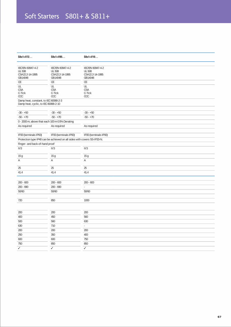
S8x1+V72… S8x1+V85… S8x1+V10…
IEC/EN 60947-4-2UL 508CSA22.2-14-1995GB14048
IEC/EN 60947-4-2UL 508CSA22.2-14-1995GB14048
IEC/EN 60947-4-2UL 508CSA22.2-14-1995GB14048
CE CE CEULCSAC-TickCCC
ULCSAC-TickCCC
ULCSAC-TickCCC
Damp heat, constant, to IEC 60068-2-3Damp heat, cyclic, to IEC 60068-2-10
-30 - +50 -30 - +50 -30 - +50-50 - +70 -50 - +70 -50 - +700 - 2000 m, above that each 100 m 0.5% DeratingAs required As required As required
IP20 (terminals IP00) IP20 (terminals IP00) IP20 (terminals IP00)Protection type IP40 can be achieved on all sides with covers SS-IP20-N.Finger- and back-of-hand proofII/3 II/3 II/3
15 g 15 g 15 gA A A
25 25 2541.4 41.4 41.4
200 - 600 200 - 600 200 - 600200 - 690 200 - 690 -50/60 50/60 50/60
720 850 1000
200 200 200400 450 560500 560 630630 710 -200 200 200250 350 400600 600 750750 850 850
68
Soft Starters S801+ & S811+
S8x1+V36… S8x1+V42… S8x1+V50… S8x1+V65…
Soft start function
Ramp timesAcceleration s 180 180 180 180Deceleration s 0 - 60 0 - 60 0 - 60 0 - 60
Start pedestal % 85 85 85 85Kickstart
Voltage % 100 100 100 100Duration
50 Hz ms 2000 2000 2000 200060 Hz ms 2000 2000 2000 2000
Fields of applicationFields of application Soft starting of three-phase asynchronous motors3-phase motors
Functions
Fast switching (semiconductor contactor)
- (minimum ramp time 1s)
Soft start functionReversing starter External solution required (reversing contactor)Suppression of closing transientsCurrent limitationOverload monitoringUnderload monitoringFault memory Faults 10 10 10 10Suppression of DC components for motorsPotential isolation between power and control sectionsBuilt-in interfaces Modbus RTU Modbus RTU Modbus RTU Modbus RTU
69
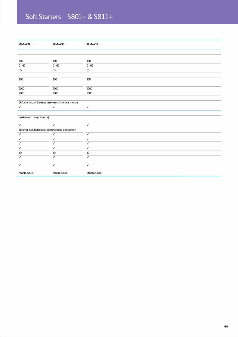
Soft Starters S801+ & S811+
S8x1+V72… S8x1+V85… S8x1+V10…
180 180 1800 - 60 0 - 60 0 - 6085 85 85
100 100 100
2000 2000 20002000 2000 2000
Soft starting of three-phase asynchronous motors
- (minimum ramp time 1s)
External solution required (reversing contactor)
10 10 10
Modbus RTU Modbus RTU Modbus RTU
70
Soft Starters DS 7 Soft Start Controllers
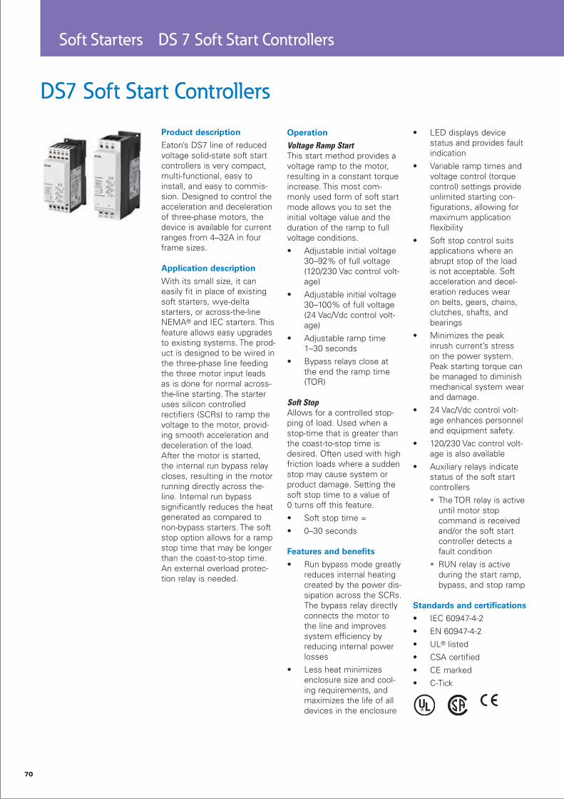
DS7 Soft Start Controllers
Product description
Eaton’s DS7 line of reducedvoltage solid-state soft startcontrollers is very compact,multi-functional, easy toinstall, and easy to commis-sion. Designed to control the acceleration and deceleration of three-phase motors, the device is available for current ranges from 4–32A in four frame sizes.
Application description
With its small size, it caneasily fit in place of existingsoft starters, wye-deltastarters, or across-the-lineNEMA® and IEC starters. This feature allows easy upgrades to existing systems. The prod-uct is designed to be wired in the three-phase line feeding the three motor input leads as is done for normal across-the-line starting. The starter uses silicon controlledrectifiers (SCRs) to ramp thevoltage to the motor, provid-ing smooth acceleration anddeceleration of the load. After the motor is started, the internal run bypass relay closes, resulting in the motorrunning directly across the-line. Internal run bypasssignificantly reduces the heat generated as compared to non-bypass starters. The soft stop option allows for a ramp stop time that may be longer than the coast-to-stop time. An external overload protec-tion relay is needed.
Operation
Voltage Ramp StartThis start method provides avoltage ramp to the motor,resulting in a constant torqueincrease. This most com-monly used form of soft start mode allows you to set the initial voltage value and the duration of the ramp to full voltage conditions.
Adjustable initial voltage • 30–92% of full voltage (120/230 Vac control volt-age)
Adjustable initial voltage • 30–100% of full voltage (24 Vac/Vdc control volt-age)
Adjustable ramp time • 1–30 seconds
Bypass relays close at • the end the ramp time (TOR)
Soft StopAllows for a controlled stop-ping of load. Used when a stop-time that is greater than the coast-to-stop time is desired. Often used with highfriction loads where a suddenstop may cause system orproduct damage. Setting thesoft stop time to a value of0 turns off this feature.
Soft stop time =•
0–30 seconds•
Features and benefits
Run bypass mode greatly • reduces internal heating created by the power dis-sipation across the SCRs. The bypass relay directly connects the motor to the line and improves system efficiency by reducing internal power losses
Less heat minimizes • enclosure size and cool-ing requirements, and maximizes the life of all devices in the enclosure
LED displays device • status and provides fault indication
Variable ramp times and • voltage control (torque control) settings provide unlimited starting con-figurations, allowing for maximum application flexibility
Soft stop control suits • applications where an abrupt stop of the load is not acceptable. Soft acceleration and decel-eration reduces wear on belts, gears, chains, clutches, shafts, and bearings
Minimizes the peak • inrush current’s stress on the power system. Peak starting torque can be managed to diminish mechanical system wear and damage.
24 Vac/Vdc control volt-• age enhances personnel and equipment safety.
120/230 Vac control volt-• age is also available
Auxiliary relays indicate • status of the soft start controllers
• The TOR relay is active until motor stop command is received and/or the soft start controller detects a fault condition
• RUN relay is active during the start ramp, bypass, and stop ramp
Standards and certifications
IEC 60947-4-2•
EN 60947-4-2•
UL• ® listed
CSA certified•
CE marked•
C-Tick•

71
Soft Starters DS 7 Soft Start Controllers

72
Soft Starters DS 7 Soft Start Controllers
Technical data
DS7…004… DS7…007… DS7…009… DS7…012… DS7…016… DS7…024… DS7…032…
General
Standards IEC/EN 60947-4-2UL 508CSA22.2-14
Approvals CEApprovals UL
CSAC-TickUkrSEPRO
Climatic proofing Damp heat, constant, to IEC 60068-2-3Damp heat, cyclic, to IEC 60068-2-10
Ambient temperatureOperation °C -5 - +40
up to 60 at 2% derating per Kelvin temperature riseStorage °C -25 - +60
Altitude m 0 - 1000 m, above that 1 % derating per 100 m , up to 2000 mMounting position VerticalDegree of protection
Protection type IP20Integrated -
Protection against direct contact
Finger- and back-of-hand proof
Rated insulation voltage Ui V AC 500Overvoltage category/pollution degree
II/2
Shock resistance 8 g/11 msVibration resistance to EN 60721-3-2
2M2
Radio interference level (IEC/EN 55011)
B
…342SX… AHeat dissipation W 0.2 0.35 0.45 0.6 0.8 1.1 1.5Weight kg
…340SX…-N 0.35 0.4 1.8…342SX… 0.4 0.45 0.4…34DSX… 0.41 0.46 0.41
Main conducting paths
Rated operating voltage Ue V AC 200 - 480Supply frequency fLN Hz 50/60Rated operational current
Device (AC-53) Ie A 4 7 9 12 16 24 24Assigned motor rating (Standard connection, In-Line)
at 230 V, 50 Hz P kW 0.75 1.5 2.2 3 4 5.5 5.5at 400 V, 50 Hz P kW 1.5 3 4 5.5 7.5 11 11at 200 V, 60 Hz P HP 0.75 2 2 3 5 7.5 7.5at 230 V, 60 Hz P HP 1 2 3 3 5 7.5 7.5at 480 V, 60 Hz P HP 2 5 5 10 10 15 15
Overload cycle to IEC/EN 60947-4-2
AC-53a (without bypass) 4 A: AC-53a: 3 - 5: 75 - 10
7 A: AC-53a: 3 - 5: 75 - 10
9 A: AC-53a: 3 - 5: 75 - 10
12 A: AC-53a: 3 - 5: 75 - 10
16 A: AC-53a: 3 - 5: 75 - 10
24 A: AC-53a: 3 - 5: 75 - 10
32 A: AC-53a: 3 - 5: 75 - 10
Internal bypass contacts

73
Soft Starters DS 7 Soft Start Controllers
DS7…041… DS7…055… DS7…070… DS7…081… DS7…100… DS7…135… DS7…160… DS7…200…
IEC/EN 60947-4-2UL 508CSA22.2-14CEULCSAC-TickUkrSEPRODamp heat, constant, to IEC 60068-2-3Damp heat, cyclic, to IEC 60068-2-10
-5 - +40up to 60 at 2% derating per Kelvin temperature rise-25 - +600 - 1000 m, above that 1 % derating per 100 m , up to 2000 mVertical
IP20 (terminals IP00)Protection type IP40 can be achieved on all sides with covers from the NZM range.Finger- and back-of-hand proof
500II/2
8 g/11 ms2M2
B
A7 10 13 18 25 24 30 42
1.8 3.71.8 3.71.8 3.7
200 - 48050/60
41 55 70 81 100 135 160 200
11 15 15 22 30 30 45 5522 30 37 45 55 75 90 11010 15 20 25 30 40 50 6015 20 25 30 30 50 60 7530 40 50 60 75 100 125 150
41 A: AC-53a: 3 - 5: 75 - 10
55 A: AC-53a: 3 - 5: 75 - 10
70 A: AC-53a: 3 - 5: 75 - 10
81 A: AC-53a: 3 - 5: 75 - 10
100 A: AC-53a: 3 - 5: 75 - 10
135 A: AC-53a: 3 - 5: 75 - 10
160 A: AC-53a: 3 - 5: 75 - 10
200 A: AC-53a: 3 - 5: 75 - 10

74
Soft Starters DS 7 Soft Start Controllers
Short-circuit ratingType “1” coordination
Type “1” coordination PKM0-4 (+ CL-PKZ0)
PKM0-10(+ CL-PKZ0)
PKM0-10 (+ CL-PKZ0)
PKM0-12 (+ CL-PKZ0)
PKM0-16 (+ CL-PKZ0)
PKM0-25 (+ CL-PKZ0)
PKM0-32 (+ CL-PKZ0)
Type „2“ coordination short-circuit rating (additional with the fuses for coordination type „1“)
3 x 170M1359 3 x 170M1361 3 x 170M1362 3 x 170M1362 3 x 170M1364 3 x 170M1365 3 x 170M1366
Fuse base (number x part no.) 3 x 170H1007 3 x 170H1007 3 x 170H1007 3 x 170H1007 3 x 170H1007 3 x 170H1007 3 x 170H1007
DS7…004… DS7…007… DS7…009… DS7…012… DS7…016… DS7…024… DS7…032…
Soft start function
Ramp timesAcceleration s 1 - 30Deceleration s 0 - 30
Start pedestal % 30 - 100Current limitation
…34DSX…(+PKE) (0 - 8) x Ie
Fields of applicationFields of application Soft starting of three-phase asynchronous motors3-phase motors
Functions
Fast switching (semiconductor contactor)
- (minimum ramp time 1s)
Soft start functionReversing starter External solution requiredSuppression of closing transientsCurrent limitation
…34DSX… , with PKEOverload monitoring - - - - - - -Underload monitoring - - - - - - -Thermistor input - - - - - - -Fault memory Faults
…34DSX… 8Pre-programmed parameter sets
- - - - - - -
Suppression of DC components for motorsPotential isolation between power and control sectionsBuilt-in interfaces
…34DSX… SmartWire-DT

75
Soft Starters DS 7 Soft Start Controllers
NZMN1-M50/PKZM4-49
NZMN1-M63/PKZM4-57
NZMN1-M80 NZMN1-M100 NZMN1-M100 NZMN2-M160 NZMN2-M200 NZMN2-M200
3 x 170M3012 3 x 170M2615 3 x 170M4008 3 x 170M4008 3 x 170M4008 3 x 170M4010 3 x 170M5008 3 x 170M6008
3 x 170H3004 3 x 170H1007 3 x 170H3004 3 x 170H3004 3 x 170H3004 3 x 170H3004 3 x 170H3004 3 x 170H3004
DS7…041… DS7…055… DS7…070… DS7…081… DS7…100… DS7…135… DS7…160… DS7…200…
1 - 300 - 3030 - 100
(0 - 8) x Ie
Soft starting of three-phase asynchronous motors
- (minimum ramp time 1s)
External solution required
, with PKE- - - - - - - -- - - - - - - -- - - - - - - -
8- - - - - - - -
SmartWire-DT

76
Adjustable Frequency Drives DG 1 General Purpose Drive
DG1 General Purpose Drive
Product description
The DG1 general purposedrives are part of Eaton’s next generation PowerXL Series of adjustable fre-quency drives specifically engineered for today’s more demanding commercial and industrial applications. The power unit makes use of the most sophisticated semiconductor technology and a highly modular con-struction that can be flexibly adapted to meet the cus-tomer’s needs.
The control module wasdesigned to include today’sstandard communicationprotocols and I/O while stillhaving the modularity to addadditional option cards.
Eaton’s patented ActiveEnergy Control is also astandard feature on DG1drives, offering customersincreased efficiency, safetyand reliability.
These drives continue the tradition of robust perfor-mance and raise the bar on features and functionality, ensuring the best solution at the right price.
Product Range
0.75-90kW, 208-240V•
1.5-160kW, 380V-500V•
Features
Hardware
Brake chopper standard • on Frames 1, 2, 3
Dual overload ratings • • 110% variable torque (IL) • 150% constant torque (IH)
IP21 and IP54 enclosures • available
Integrated common • mode reduction 5% DC link choke with input surge protection
EMI/RFI filters standard • on all drives—meets EMC Category C2
Real-time clock—sup-• ports calendaring and PLC functionality
Graphic LCD display and • keypad—supports simple menu navigation as well as on-screen diagnostics and troubleshooting
LOCAL/REMOTE opera-• tion from keypad and two configurable soft keys
Control logic can be pow-• ered from an external auxiliary control panel—internal drive functions and fieldbus if necessary
Standard I/O:• • 8DI, 1DO
• 2AI, 2AO • Three relays • Meets needs of most communication requirements
Standard communications:• • Ethernet IP, Modbus TCP • RS-485: Modbus RTU
BACnet MS/TP • Meets the needs of
most communication requirements
Two expansion slots—• intended to support additional I/O or com-munication protocols as necessary
Quick disconnect ter-• minals for I/O connec-tions—supports fast easy installation

77
Adjustable Frequency Drives DG 1 General Purpose Drive

78
Adjustable Frequency Drives DG 1 General Purpose Drive
Technical data

79
Adjustable Frequency Drives DG 1 General Purpose Drive

80
Adjustable Frequency Drives M-Max Adjustable Frequency AC Drive
M-Max Series Drives for Machinery Applications
Product description
Eaton’s M-Max™ SeriesSensorless Vector Adjustable Frequency AC Drives are the next generation of drives specifically engineered for today’s machinery applica-tions. These microprocessor-based drives have stan-dard features that can be programmed to tailor the drive’s performance to suit a wide variety of application requirements. The M-Maxproduct line uses a 32-bitmicroprocessor and insulat-ed gate bipolar transistors(IGBTs) that provide quietmotor operation, high motorefficiency, and smooth low-speed performance. The sizeand simplicity of the M-Maxmake it ideal for hassle-free
installation. Models rated at575 volts, three-phase, 50/60 Hz are available in sizes rang-ing from 0.75kW to 3kW. Models rated at 400 volts, three-phase, 50/60 Hzare available in sizes rangingfrom 0.25kW to 18.5kW. Models rated at 220 volts, single- or three-phase, 50/60 Hz are available in sizes rang-ing from 0.25kW to 2.2kW. Models ratedat 110 volts, single-phase, 50/60 Hz are available in the0.25kW to 1.1kW size range.
The standard drive includes adigital display, and operatingand programming keys on avisually appealing, efficientapplication programminginterface. The display provides drive monitoring, as well as adjustment and diagnostic information. The keys are used for digital adjustment and programming of the drive, as well as for operator control. Separate terminal blocks for control and power wiring are provided for cus-tomer connections.
Features
Ease of use—preset • application macros, startup wizard, diagnostic capabilities
Compact, space-saving • design
Rugged and reliable—• 150% for one minute, 50°C rated, conformal-coated boards
DIN rail and screw • mountable
Side-by-side installation•
Industry leading effciency • delivers energy savings to the customer
Integrated EMC filters-• make the unit suitable for commercial and industrial networks
Available in the enclosure • class IP20 as standard, options for IP21
Brake chopper as stan-• dard in three-phase, applications of frames 2 (FS2) and larger
Temperature-controlled • fan RS-485/Modbus® as standard
PID controller as stan-• dard
Several fieldbus options•
Standards and certifications
Product
Complies with • EN61800-3 (2004)
Safety61800-5-1•
EN60204-1•
CE•
UL•
cUL•
IEC•
RoHS compliant•
EMC (At Default Settings)EMC Category C2, C3, • and C4 (Level H): With an internal RFI filter option

81
Adjustable Frequency Drives M-Max Adjustable Frequency AC Drive
Technical data
82
Adjustable Frequency Drives DE1 Variable Speed Drive
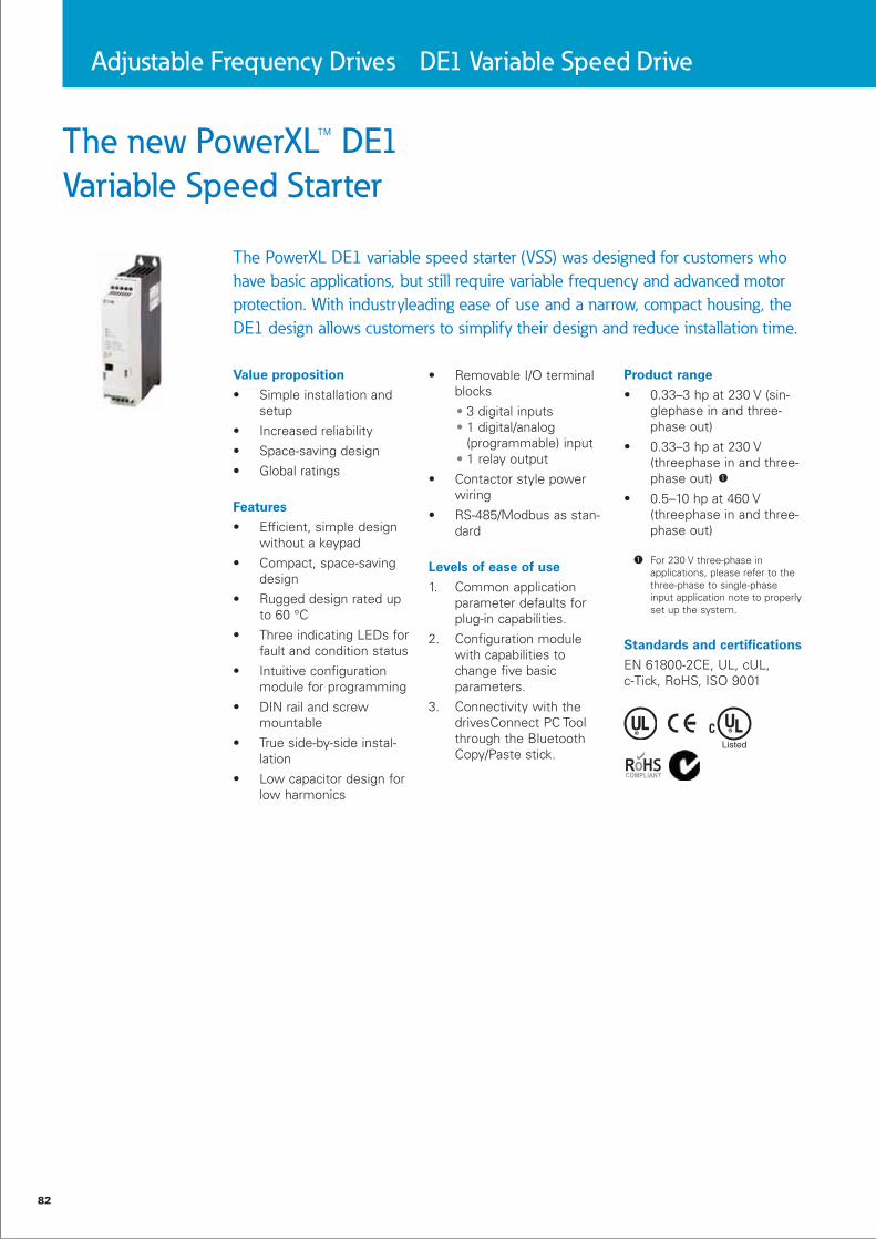
The new PowerXL™ DE1
Variable Speed Starter
The PowerXL DE1 variable speed starter (VSS) was designed for customers who
have basic applications, but still require variable frequency and advanced motor
protection. With industryleading ease of use and a narrow, compact housing, the
DE1 design allows customers to simplify their design and reduce installation time.
Value proposition
Simple installation and • setup
Increased reliability•
Space-saving design•
Global ratings•
Features
Efficient, simple design • without a keypad
Compact, space-saving • design
Rugged design rated up • to 60 °C
Three indicating LEDs for • fault and condition status
Intuitive configuration • module for programming
DIN rail and screw • mountable
True side-by-side instal-• lation
Low capacitor design for • low harmonics
Removable I/O terminal • blocks
• 3 digital inputs • 1 digital/analog (programmable) input • 1 relay output
Contactor style power • wiring
RS-485/Modbus as stan-• dard
Levels of ease of use
1. Common application parameter defaults for plug-in capabilities.
2. Configuration module with capabilities to change five basic parameters.
3. Connectivity with the drivesConnect PC Tool through the Bluetooth Copy/Paste stick.
Product range
0.33–3 hp at 230 V (sin-• glephase in and three-phase out)
0.33–3 hp at 230 V • (threephase in and three-phase out)
0.5–10 hp at 460 V • (threephase in and three-phase out)
For 230 V three-phase in applications, please refer to the three-phase to single-phase input application note to properly set up the system.
Standards and certifications
EN 61800-2CE, UL, cUL, c-Tick, RoHS, ISO 9001

83
Adjustable Frequency Drives DE1 Variable Speed Drive
Technical data

84
Pushbuttons & Indicating Lights A22
Pushbutton and indicating light A22
In accordance with IEC/EN 60947 and VDE0660•
Modular structure is suitable for different application requirements•
They can be mounted without any need for tools•
Contact blocks are finger touch safe•
Up to 6 contact blocks can be mounted on each mounting location•

85
Pushbuttons & Indicating Lights A22
Technical data

86
Pushbuttons & Indicating Lights A22
Technical data

87
Cam Switches / Switch Disconnectors T Cam Switch
Safe Switching, Isolating and Control with
Rotary Switch T and Switch Disconnector P
The high-performance, robust and compact T rotary switches and P switch-disconnec-tors are used in industry, trade and building engineering applications. The degree of protection IP65 with the switch mounts and the switch front enables use in harsh envi-ronments. Ten basic switch types in four different construction types, in a whole range of standard switches and across a wide performance range are available. Customised circuits can also be implemented in addition to the standard configurations. The pos-sibilities are almost unlimited. A comprehensive accessory range complements the switch range and rounds off the range of applications. All contacts feature double breaking contacts.
With the metal extension shafts our reliable P1 and P3 switches can be mounted in electrical cabinets of up to 600 mm deep and with several Handle and Shaft options a solution can be found for every application. Also the most common types are available as a complete switch/shaft/handle package.
Rotary switch T
The rotary switch T represents a very flexible, compact and robust modular system. The TM, T0, T3, T5B, T5, T6, T8 rating sizes are available in four different construction types. The rating of the T switch ranges from 6.5 kW to 132 kW with AC 23 A at 400/415 V, 50-60 Hz. The rated uninterrupted current Iu is between 10 A and 315 A. The rotary switch T has a widely varied range of application uses. Customized circuits on request.
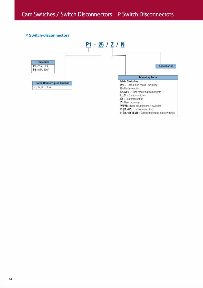
Switch-disconnector P
The switch-disconnectors P1 up to 32 A, P3 up to 100 A, P5 up to 315 A are very com-pact and robust. The manual operator acts directly on the contacts. The contacts are positively opened on de-energization. In addition to their use as switch disconnectors with and without the Emergency-Stop function, switch-disconnectors P can be used as On-Off switches as well as maintenance, manual override or safety switches.

88
Cam Switches / Switch Disconnectors T Cam Switch

89
Cam Switches / Switch Disconnectors T Cam Switch

90
Cam Switches / Switch Disconnectors T Cam Switch
Technical data

91
Cam Switches / Switch Disconnectors T Cam Switch

92
Cam Switches / Switch Disconnectors P Switch Disconnectors

93
Cam Switches / Switch Disconnectors P Switch Disconnectors
94
Cam Switches / Switch Disconnectors P Switch Disconnectors

95
Cam Switches / Switch Disconnectors P Switch Disconnectors
Technical data

At Eaton, we’re energized by the challenge of powering a world that demands more. With over 100 years’ experience in electrical power management, we have the expertise to see beyond today. From groundbreaking products to turnkey design and engineering services, critical industries around the globe count on Eaton.
We power businesses with reliable, efficient and safe electrical power management solutions. Combined with our personal service, support and bold thinking, we are answering tomorrow’s needs today. Follow the charge with Eaton. Visit www.eaton.com/seasia-electrical.
Electrical Sector, East Asia
Power DistributionEaton Industries Pte Ltd4 Loyang Lane #04-01/02Singapore 508914
© 2014 Eaton CorporationAll Rights ReservedPrinted in SingaporeArticle No: pan_ea0960315March 2015