cim manual - modbus-v00.3 - electroswitch manual - modbus-v00.3.doc; rev. 0.3 page 4 of 42...
TRANSCRIPT
CIM Manual - Modbus-V00.3.doc; Rev. 0.3 Page 1 of 42
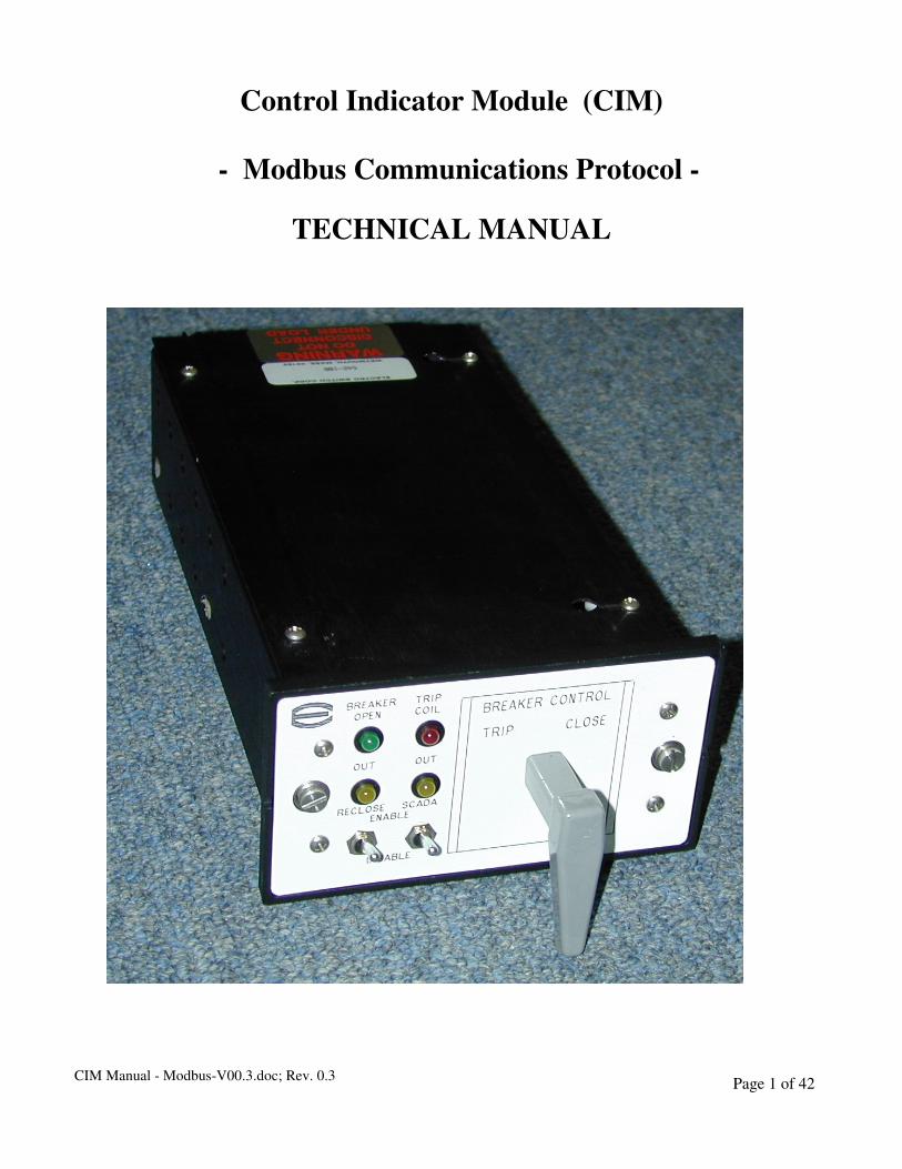
Control Indicator Module (CIM)
- Modbus Communications Protocol -
TECHNICAL MANUAL

CIM Manual - Modbus-V00.3.doc; Rev. 0.3 Page 2 of 42
Introduction...................................................................................................................................................4
Basic Operation.............................................................................................................................................5
Front Panel Controls and Indicators.....................................................................................................................5
Real Time Clock Battery Back Up.........................................................................................................................8
SCADA Communication System ..................................................................................................................9
Modbus Protocol .....................................................................................................................................................9
Serial Transmission Details..................................................................................................................................11
Communications Hardware Requirements ........................................................................................................12
Sessions...................................................................................................................................................................22
Command Description..........................................................................................................................................23
Single Trip Coil Mode.................................................................................................................................24
Configuring the CIM for Single Trip Mode .......................................................................................................25
Control Functions in Single Trip Coil Mode ......................................................................................................26
Connections in Single Trip Coil Mode ................................................................................................................29
Dual Trip Coil Mode ...................................................................................................................................30
Configuring the CIM for Dual Trip Coil Mode .................................................................................................31
Control Functions in Dual Trip Coil Mode ........................................................................................................32
Connections in Dual Trip Coil Mode...................................................................................................................35
Circuit Switcher or Ganged Single Pole Breakers Mode ..........................................................................36
Configuring the CIM for Circuit Switcher or Ganged Single Pole Breakers Mode .......................................37
Control Functions in Circuit Switcher or Ganged Single Pole Breakers Mode..............................................38
Connections in Circuit Switcher of Ganged Single Pole Breakers Mode.........................................................41
Specifications and Tests ..............................................................................................................................42
Operating Voltage .................................................................................................................................................42
TRIP Contact Ratings...........................................................................................................................................42
CLOSE/Reclose Contact Ratings.........................................................................................................................42
SCADA Contact Ratings ......................................................................................................................................42
SCADA Input ............................................................................................................ Error! Bookmark not defined.
External ReClose Output .....................................................................................................................................42
Ambient Temperature Rating..............................................................................................................................42
Surge Withstand Capability.................................................................................................................................42
EMI/RFI (Radio Frequency Immunity)..............................................................................................................42
Dielectric Withstand Voltage ...............................................................................................................................42
Tested Life Under Rated Load.............................................................................................................................42

CIM Manual - Modbus-V00.3.doc; Rev. 0.3 Page 3 of 42
Environmental Testing .........................................................................................................................................42

CIM Manual - Modbus-V00.3.doc; Rev. 0.3 Page 4 of 42
Introduction
The Control Indicator Module (CIM) unit is a Breaker Control Switch with expanded functionality. It
provides remote/local circuit breaker control (trip/close), remote/local Recloser Relay control, and
Breaker Trip Coil monitoring. The CIM contains a serial (Modbus) SCADA interface for remote control
and monitoring functions. All controls, indicators and solid state electronic circuitry are contained within
a single modular enclosure that can be horizontally or vertically panel mounted within the limits of a
standard 19-inch rack system.
The CIM does not depend upon external software or require paging through menus on a screen. The
product is operated with simple front panel controls and configured with one four position internal
switch. The CIM provides the following benefits:
- Security – supervisory remote control from operations control center via SCADA.
- Confidence – providing a local manual operated switch for emergency conditions.
- Training – minimum training required, present equipment in service with similar functions.
- Immediate Control–no delay in locating the correct display or proper control sequence.
The CIM unit is applicable in any breaker control scheme for either Transmission and/or Distribution
substations or switchyards. It provides for manual local or remote automatic control of switchable
equipment. The CIM unit is easy to use, requires minimum training, and provides immediate control of
equipment in the event of emergencies.
The CIM unit replaces three switches and six indicator lights located on a breaker control panel. The CIM
contains a breaker control switch, two LED’s which indicate the status of the breaker, two LED’s which
indicate the status of SCADA and Reclose enable, and switches enabling/disabling SCADA and Reclose.
Power, control and SCADA connections are at the rear of the CIM.
The CIM can be configured in one of three modes:
A. Single trip coil mode, in which a breaker with one trip coil is controlled and monitored.
B. Dual trip coil in which two separate, isolated trip coils are monitored and controlled.
C. Circuit switcher or ganged single pole breakers mode, in which three trip coils are monitored.
CIM Manual - Modbus-V00.3.doc; Rev. 0.3 Page 5 of 42
Basic Operation
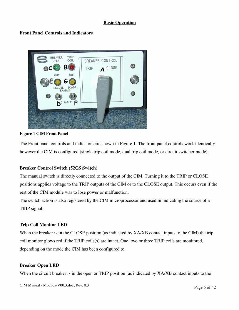
Front Panel Controls and Indicators
Figure 1 CIM Front Panel
The Front panel controls and indicators are shown in Figure 1. The front panel controls work identically
however the CIM is configured (single trip coil mode, dual trip coil mode, or circuit switcher mode).
Breaker Control Switch (52CS Switch)
The manual switch is directly connected to the output of the CIM. Turning it to the TRIP or CLOSE
positions applies voltage to the TRIP outputs of the CIM or to the CLOSE output. This occurs even if the
rest of the CIM module was to lose power or malfunction.
The switch action is also registered by the CIM microprocessor and used in indicating the source of a
TRIP signal.
Trip Coil Monitor LED
When the breaker is in the CLOSE position (as indicated by XA/XB contact inputs to the CIM) the trip
coil monitor glows red if the TRIP coils(s) are intact. One, two or three TRIP coils are monitored,
depending on the mode the CIM has been configured to.
Breaker Open LED
When the circuit breaker is in the open or TRIP position (as indicated by XA/XB contact inputs to the
CIM Manual - Modbus-V00.3.doc; Rev. 0.3 Page 6 of 42
CIM) the Breaker Open LED will glow green. The source of the TRIP signal that opened the breaker is
also indicated:
Continuous Green Light – Trip Caused by external protective relay.
Slow Flashing Green Light – Manual Trip from 52CS switch.
Fast Flashing Green Light – Trip from SCADA.
ReClose Enable/Disable Switch
When this switch is in the Disable position the CIM blocks an external ReClose relay. If this switch is in
the Enable position, then ReClose can be remotely Enabled or Disabled. If the switch is in the disable
position, then ReClose cannot be remotely enabled.
ReClose ‘OUT’ LED
The Amber ReClose ‘OUT’ LED is lit when Reclose is Disabled via the local manual switch or a SCADA
command. The front panel switch has priority.
The LED flashes when there is a SCADA Lockout Reclose command received. The LED stops flashing
(Not Lit) when there is a SCADA Enable command received.
SCADA Enable/Disable Switch
This toggle switch enables/disables SCADA commands. Status can still be read, however.
SCADA ‘OUT’ LED
The amber SCADA Enable/Disable LED is lit when SCADA is disabled.
CIM Manual - Modbus-V00.3.doc; Rev. 0.3 Page 7 of 42
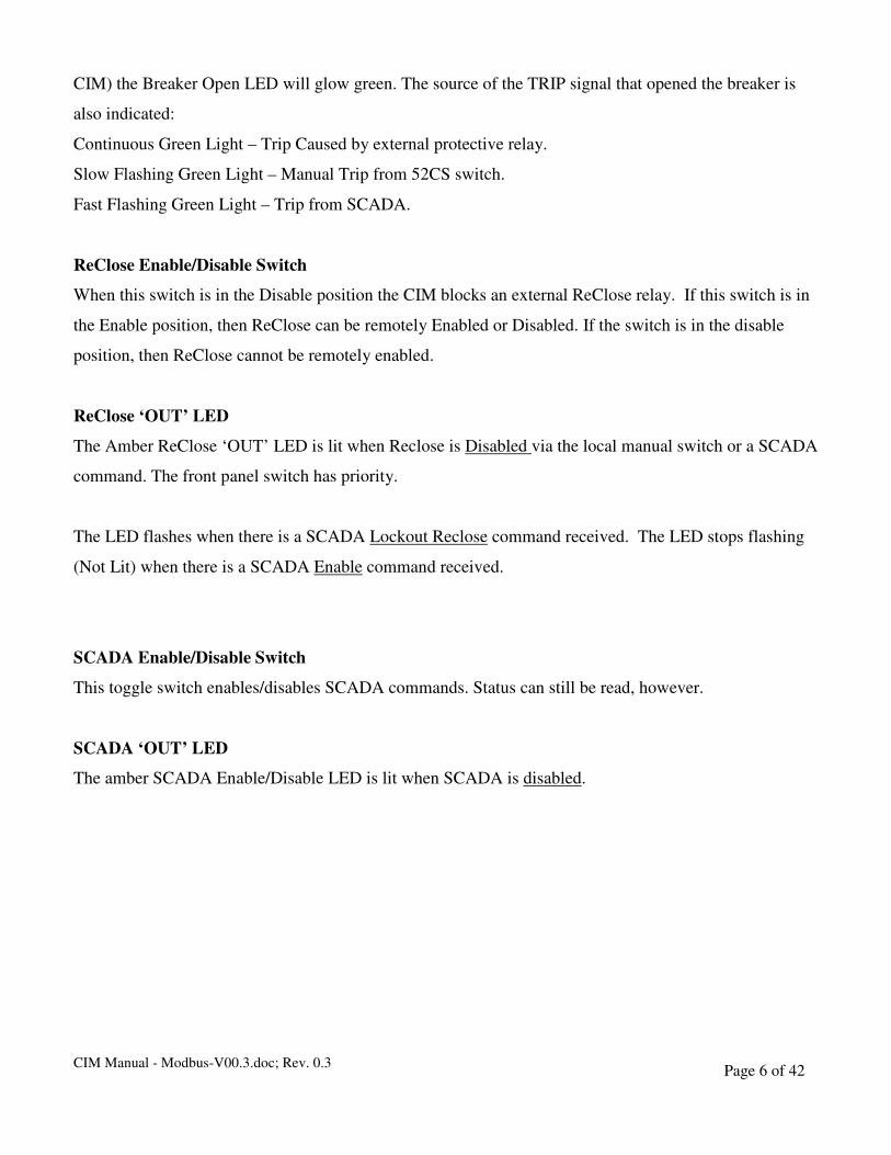
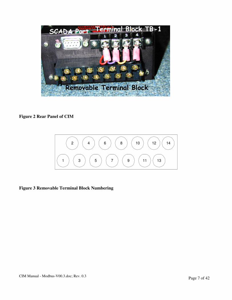
Figure 2 Rear Panel of CIM
Figure 3 Removable Terminal Block Numbering
1 3 5 7 9 11 13
2 4 6 8 10 12 14

CIM Manual - Modbus-V00.3.doc; Rev. 0.3 Page 8 of 42
Real Time Clock Battery Back Up
The real time clock on the communications board has a battery back up circuit that keeps the clock
running even when the main power to the CIM has been removed. This battery is electrically removed
from the circuit when the CIM is powered and is electrically connected when the power is removed. This
configuration will allow the clock to run for up to 25 years after the power is removed from the CIM.
While the clock is always running events are not stored while the main power is removed from the CIM.
If it is desired to replace the battery then access to it can be obtained by removing the top cover of
the CIM. Located on the right front of the communications board, when looking at the front of the unit, is
the battery holder. There is a tab on top that holds the battery in place. Carefully remove the battery by
lifting up on the right hand side and sliding the battery out towards the right. To install the new battery
simply reverse the process making sure that the positive side of the battery is on top. The replacement
battery should be a 3 volt lithium with a part number CR2032 or its replacement.
Battery
CIM Manual - Modbus-V00.3.doc; Rev. 0.3 Page 9 of 42
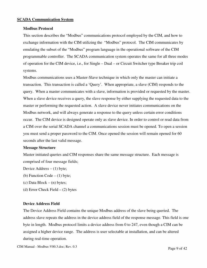
SCADA Communication System
Modbus Protocol
This section describes the “Modbus” communications protocol employed by the CIM, and how to
exchange information with the CIM utilizing the “Modbus” protocol. The CIM communicates by
emulating the subset of the “Modbus” program language in the operational software of the CIM
programmable controller. The SCADA communication system operates the same for all three modes
of operation for the CIM device, i.e., for Single – Dual – or Circuit Switcher type Breaker trip coil
systems.
Modbus communications uses a Master-Slave technique in which only the master can initiate a
transaction. This transaction is called a ‘Query’. When appropriate, a slave (CIM) responds to the
query. When a master communicates with a slave, information is provided or requested by the master.
When a slave device receives a query, the slave response by either supplying the requested data to the
master or performing the requested action. A slave device never initiates communications on the
Modbus network, and will always generate a response to the query unless certain error conditions
occur. The CIM device is designed operate only as slave device. In order to control or read data from
a CIM over the serial SCADA channel a communications session must be opened. To open a session
you must send a proper password to the CIM. Once opened the session will remain opened for 60
seconds after the last valid message.
Message Structure
Master initiated queries and CIM responses share the same message structure. Each message is
comprised of four message fields;
Device Address – (1) byte;
(b) Function Code – (1) byte;
(c) Data Block – (n) bytes;
(d) Error Check Field – (2) bytes
Device Address Field
The Device Address Field contains the unique Modbus address of the slave being queried. The
address slave repeats the address in the device address field of the response message. This field is one
byte in length. Modbus protocol limits a device address from 0 to 247, even though a CIM can be
assigned a higher device range. The address is user selectable at installation, and can be altered
during real-time operation.
CIM Manual - Modbus-V00.3.doc; Rev. 0.3 Page 10 of 42
Address zero is a Modbus broadcast address, however, it does not return a reply. This address can be used
to program the CIM for the first 30 seconds after the IED is reset and then only for the enter password and
set address command.
Function Code Field
The Function Code Field in the query message defines the action to be taken by the addressed slave. This
field is echoed in the response message, and is altered by setting the most significant bit (MSB) of the
field to 1 if the response is an error response. The field is one byte in length.
The CIM maps all stored information and data into holding registers address space (4XXXX) and
supports the following function codes;
Function 03 (03h) – Read Holding Registers
Function 05 (05h) – Force Single Coil
Function 08 (08h) – Diagnostic Subfunction 0
Function 16 (10h) – Preset Multiple Registers
Data Block
The query data block contains additional information needed by the slave to perform the requested
function. The response data block contains data collected by the slave device for the queried function.
An error response will substitute an exception response code for the data block. The length of this field
varies with each query.
Error Check Field
The error check field provides a method for the slave to validate the integrity of the query message
contents and allows the master to confirm the validity of response message contents. The field is two
bytes in length.
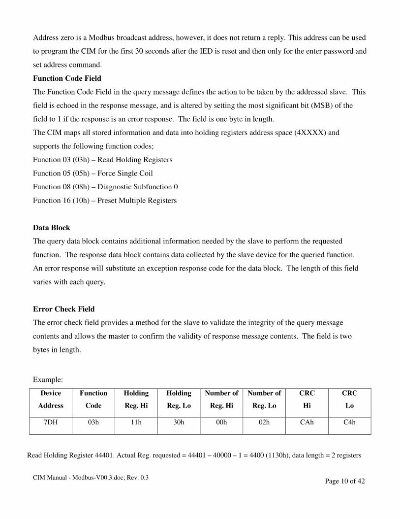
Example:
Device
Address
Function
Code
Holding
Reg. Hi
Holding
Reg. Lo
Number of
Reg. Hi
Number of
Reg. Lo
CRC
Hi
CRC
Lo
7DH 03h 11h 30h 00h 02h CAh C4h
Read Holding Register 44401. Actual Reg. requested = 44401 – 40000 – 1 = 4400 (1130h), data length = 2 registers

CIM Manual - Modbus-V00.3.doc; Rev. 0.3 Page 11 of 42
Serial Transmission Details
A standard Modbus network offers two transmission modes for communications. ASCII or Remote
Terminal Unit (RTU). The CIM supports only the RTU mode. The message is transmitted in a
continuous stream with the LSB of each byte of data transmitted first. Transmission of each 8-bit data
byte occurs with one start bit and one stop bit. Parity checking is performed, when enabled, and can
be either odd or even. The transmission baud rate is user-selectable, and can be set at installation and
altered during real-time operation if required. The CIM baud rates are 1200, 2400, 4800, and 9600.
The factory default baud rate is 9600. Contact the factory for other baud rates. These parameters are
set with dip switches on the communications daughter board.
Shown for 9600 Baud – No Parity (In the table X means – Doesn’t matter)
Sw # 8 7 6 5 4 3 2 1
9600 X X X X X OFF OFF OFF
4800 X X X X X OFF OFF ON
2400 X X X X X OFF ON OFF
1200 X X X X X OFF ON ON
NONE X X X OFF OFF X X X
ODD X X X OFF ON X X X
EVEN X X X ON OFF X X X
Spare X X X X X X X X
Spare X X X X X X X X
8 7 6 5 4 3 2 1
ON
CIM Manual - Modbus-V00.3.doc; Rev. 0.3 Page 12 of 42
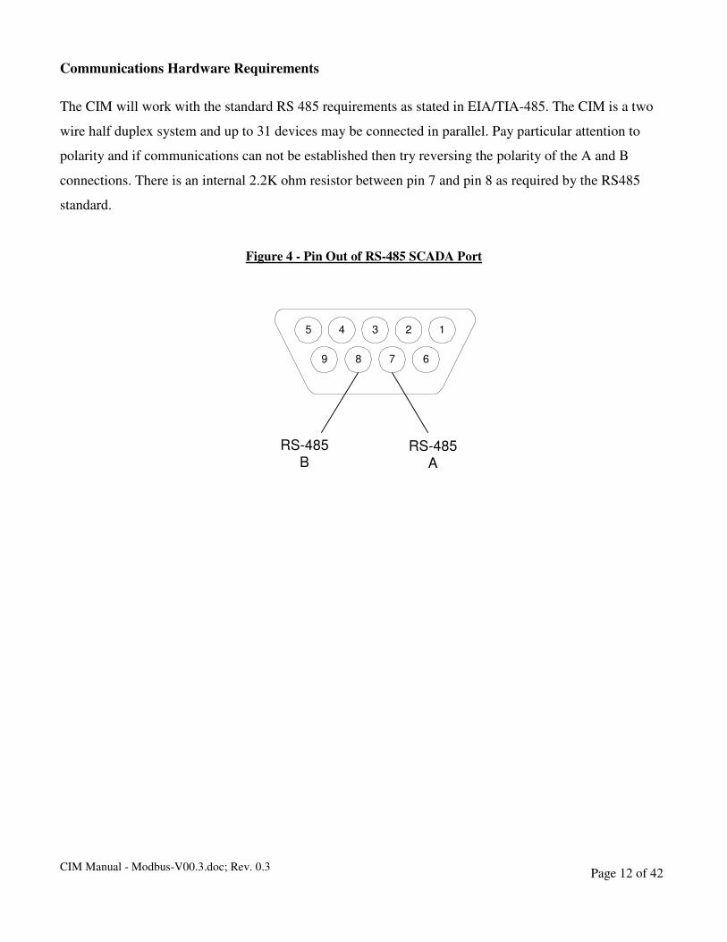
Communications Hardware Requirements
The CIM will work with the standard RS 485 requirements as stated in EIA/TIA-485. The CIM is a two
wire half duplex system and up to 31 devices may be connected in parallel. Pay particular attention to
polarity and if communications can not be established then try reversing the polarity of the A and B
connections. There is an internal 2.2K ohm resistor between pin 7 and pin 8 as required by the RS485
standard.
Figure 4 - Pin Out of RS-485 SCADA Port
5 4 3 2 1
9 8 7 6
RS-485
BRS-485
A
CIM Manual - Modbus-V00.3.doc; Rev. 0.3 Page 13 of 42
Message Framing and Timing
When receiving a message, the CIM requires messages to with a silent interval of at least 3.5 character
times before considering the message complete. The allowable characters transmitted for all fields are
hexadecimal 0 ... 9, A ... F. This is most easily implemented as a multiple of character times at the baud
rate that is being used on the network (shown as T1-T2-T3-T4 in the chart below). The first field then
transmitted is the device address. Following the last transmitted character, a similar interval of at least 3.5
character times marks the end of the message. A new message can begin after this interval.
The entire message frame must be transmitted as a continuous stream. If a silent interval of more than 1.5
character times occurs before completion of the frame, the receiving device flushes the incomplete
message and assumes that the next byte will be the address field of a new message. Similarly, if a new
message begins earlier than 3.5 character times following a previous message, the receiving device will
consider it a continuation of the previous message. This will set an error, as the value in the final CRC
field will not be valid for the combined messages.
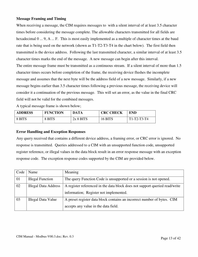
A typical message frame is shown below;
ADDRESS FUNCTION DATA CRC CHECK END
8 BITS 8 BITS 2x 8 BITS 16 BITS T1-T2-T3-T4
Error Handling and Exception Responses
Any query received that contains a different device address, a framing error, or CRC error is ignored. No
response is transmitted. Queries addressed to a CIM with an unsupported function code, unsupported
register reference, or illegal values in the data block result in an error response message with an exception
response code. The exception response codes supported by the CIM are provided below.
Code Name Meaning
01 Illegal Function The query Function Code is unsupported or a session is not opened.
02 Illegal Data Address A register referenced in the data block does not support queried read/write
information; Register not implemented.
03 Illegal Data Value A preset register data block contains an incorrect number of bytes. CIM
accepts any value in the data field.
CIM Manual - Modbus-V00.3.doc; Rev. 0.3 Page 14 of 42
FUNCTION DESCRIPTION Query
A CIM will respond to communications that are addressed to it if the CRC check passes indicating an
error free message. Also in the units with parity enabled this test must also be correct for a CIM to
respond. If either the CRC fails or any byte that fails parity during a message then the message is thrown
out and no response takes place. Once a message is accepted by the CIM it will perform one of the
following actions:
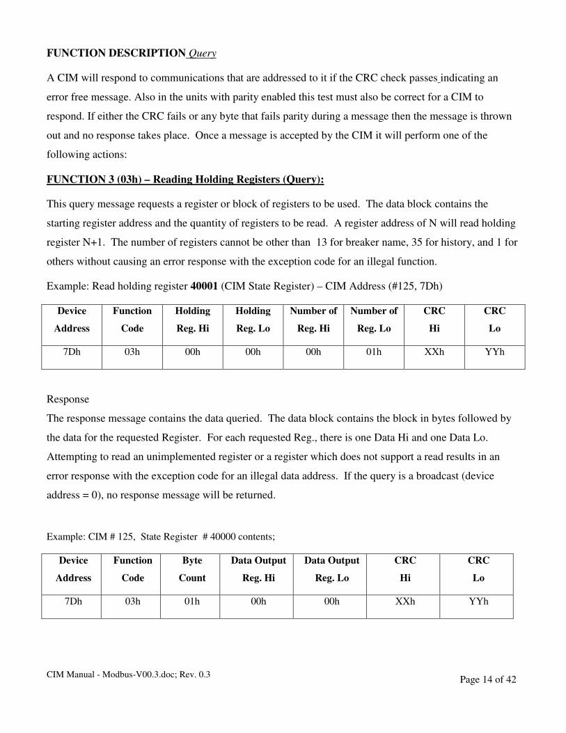
FUNCTION 3 (03h) – Reading Holding Registers (Query):
This query message requests a register or block of registers to be used. The data block contains the
starting register address and the quantity of registers to be read. A register address of N will read holding
register N+1. The number of registers cannot be other than 13 for breaker name, 35 for history, and 1 for
others without causing an error response with the exception code for an illegal function.
Example: Read holding register 40001 (CIM State Register) – CIM Address (#125, 7Dh)
Device
Address
Function
Code
Holding
Reg. Hi
Holding
Reg. Lo
Number of
Reg. Hi
Number of
Reg. Lo
CRC
Hi
CRC
Lo
7Dh 03h 00h 00h 00h 01h XXh YYh
Response
The response message contains the data queried. The data block contains the block in bytes followed by
the data for the requested Register. For each requested Reg., there is one Data Hi and one Data Lo.
Attempting to read an unimplemented register or a register which does not support a read results in an
error response with the exception code for an illegal data address. If the query is a broadcast (device
address = 0), no response message will be returned.
Example: CIM # 125, State Register # 40000 contents;
Device
Address
Function
Code
Byte
Count
Data Output
Reg. Hi
Data Output
Reg. Lo
CRC
Hi
CRC
Lo
7Dh 03h 01h 00h 00h XXh YYh
CIM Manual - Modbus-V00.3.doc; Rev. 0.3 Page 15 of 42
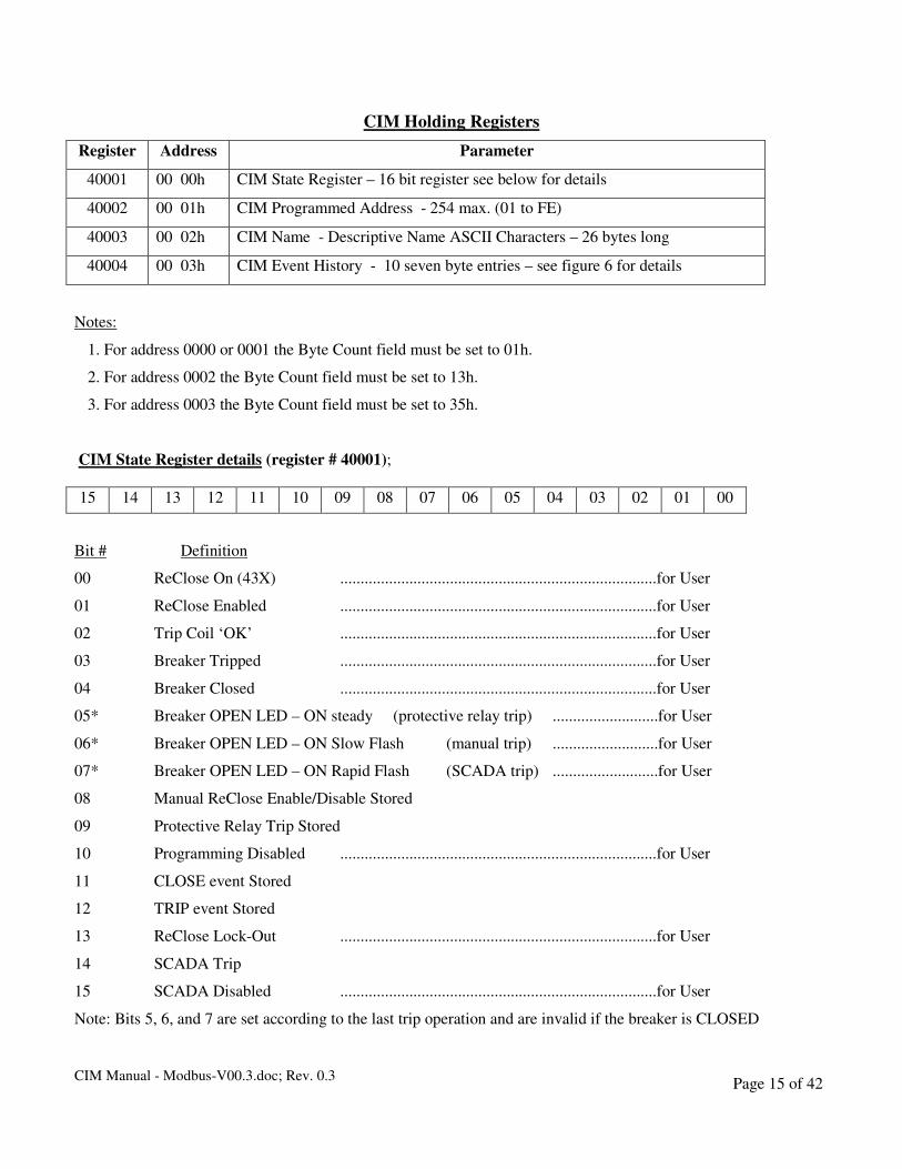
CIM Holding Registers
Register Address Parameter
40001 00 00h CIM State Register – 16 bit register see below for details
40002 00 01h CIM Programmed Address - 254 max. (01 to FE)
40003 00 02h CIM Name - Descriptive Name ASCII Characters – 26 bytes long
40004 00 03h CIM Event History - 10 seven byte entries – see figure 6 for details
Notes:
1. For address 0000 or 0001 the Byte Count field must be set to 01h.
2. For address 0002 the Byte Count field must be set to 13h.
3. For address 0003 the Byte Count field must be set to 35h.
CIM State Register details (register # 40001);
15 14 13 12 11 10 09 08 07 06 05 04 03 02 01 00
Bit # Definition
00 ReClose On (43X) ..............................................................................for User
01 ReClose Enabled ..............................................................................for User
02 Trip Coil ‘OK’ ..............................................................................for User
03 Breaker Tripped ..............................................................................for User
04 Breaker Closed ..............................................................................for User
05* Breaker OPEN LED – ON steady (protective relay trip) ..........................for User
06* Breaker OPEN LED – ON Slow Flash (manual trip) ..........................for User
07* Breaker OPEN LED – ON Rapid Flash (SCADA trip) ..........................for User
08 Manual ReClose Enable/Disable Stored
09 Protective Relay Trip Stored
10 Programming Disabled ..............................................................................for User
11 CLOSE event Stored
12 TRIP event Stored
13 ReClose Lock-Out ..............................................................................for User
14 SCADA Trip
15 SCADA Disabled ..............................................................................for User
Note: Bits 5, 6, and 7 are set according to the last trip operation and are invalid if the breaker is CLOSED

CIM Manual - Modbus-V00.3.doc; Rev. 0.3 Page 16 of 42
CIM Event History Register details (register # 40004);
Event Database Description
The following described the Event Database that is stored in the CIM memory and returned over the serial
channel when requested.
Record 00;
EVENT Seconds Minutes Hours Day Month Year
.
. .
.
.
.
Record 09
EVENT Seconds Minutes Hours Day Month Year
EVENT Description Decimal Code
Manual Trip 129
SCADA Trip 130
Protective Relay Trip 131
Manual Close 132
SCADA Close 133
Manual ReClose Disable 134
Manual ReClose Enable 135
SCADA ReClose Disabled 136
SCADA ReClose Enabled 137
SCADA Disable 138
SCADA Enable 139

CIM Manual - Modbus-V00.3.doc; Rev. 0.3 Page 17 of 42
CIM Manual - Modbus-V00.3.doc; Rev. 0.3 Page 18 of 42
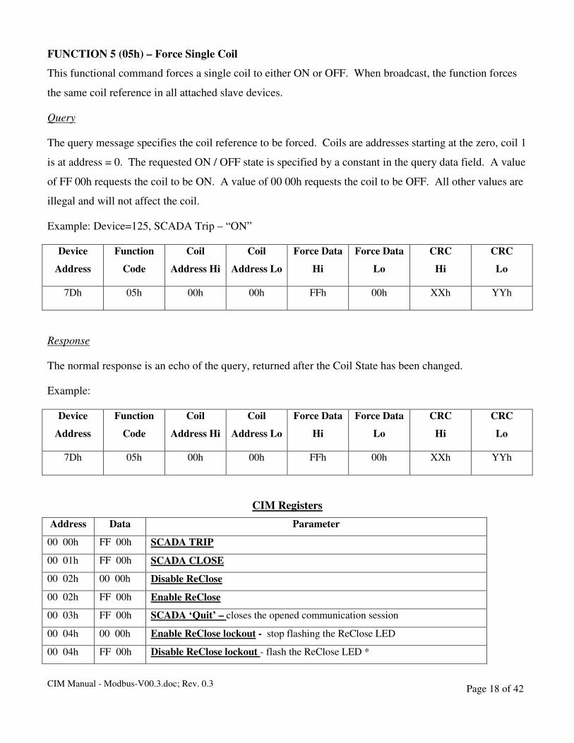
FUNCTION 5 (05h) – Force Single Coil
This functional command forces a single coil to either ON or OFF. When broadcast, the function forces
the same coil reference in all attached slave devices.
Query
The query message specifies the coil reference to be forced. Coils are addresses starting at the zero, coil 1
is at address = 0. The requested ON / OFF state is specified by a constant in the query data field. A value
of FF 00h requests the coil to be ON. A value of 00 00h requests the coil to be OFF. All other values are
illegal and will not affect the coil.
Example: Device=125, SCADA Trip – “ON”
Device
Address
Function
Code
Coil
Address Hi
Coil
Address Lo
Force Data
Hi
Force Data
Lo
CRC
Hi
CRC
Lo
7Dh 05h 00h 00h FFh 00h XXh YYh
Response
The normal response is an echo of the query, returned after the Coil State has been changed.
Example:
Device
Address
Function
Code
Coil
Address Hi
Coil
Address Lo
Force Data
Hi
Force Data
Lo
CRC
Hi
CRC
Lo
7Dh 05h 00h 00h FFh 00h XXh YYh
CIM Registers
Address Data Parameter
00 00h FF 00h SCADA TRIP
00 01h FF 00h SCADA CLOSE
00 02h 00 00h Disable ReClose
00 02h FF 00h Enable ReClose
00 03h FF 00h SCADA ‘Quit’ – closes the opened communication session
00 04h 00 00h Enable ReClose lockout - stop flashing the ReClose LED
00 04h FF 00h Disable ReClose lockout - flash the ReClose LED *
CIM Manual - Modbus-V00.3.doc; Rev. 0.3 Page 19 of 42
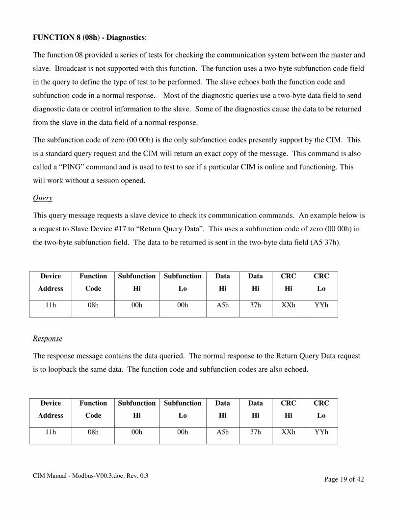
FUNCTION 8 (08h) - Diagnostics:
The function 08 provided a series of tests for checking the communication system between the master and
slave. Broadcast is not supported with this function. The function uses a two-byte subfunction code field
in the query to define the type of test to be performed. The slave echoes both the function code and
subfunction code in a normal response. Most of the diagnostic queries use a two-byte data field to send
diagnostic data or control information to the slave. Some of the diagnostics cause the data to be returned
from the slave in the data field of a normal response.
The subfunction code of zero (00 00h) is the only subfunction codes presently support by the CIM. This
is a standard query request and the CIM will return an exact copy of the message. This command is also
called a “PING” command and is used to test to see if a particular CIM is online and functioning. This
will work without a session opened.
Query
This query message requests a slave device to check its communication commands. An example below is
a request to Slave Device #17 to “Return Query Data”. This uses a subfunction code of zero (00 00h) in
the two-byte subfunction field. The data to be returned is sent in the two-byte data field (A5 37h).
Device
Address
Function
Code
Subfunction
Hi
Subfunction
Lo
Data
Hi
Data
Hi
CRC
Hi
CRC
Lo
11h 08h 00h 00h A5h 37h XXh YYh
Response
The response message contains the data queried. The normal response to the Return Query Data request
is to loopback the same data. The function code and subfunction codes are also echoed.
Device
Address
Function
Code
Subfunction
Hi
Subfunction
Lo
Data
Hi
Data
Hi
CRC
Hi
CRC
Lo
11h 08h 00h 00h A5h 37h XXh YYh

CIM Manual - Modbus-V00.3.doc; Rev. 0.3 Page 20 of 42
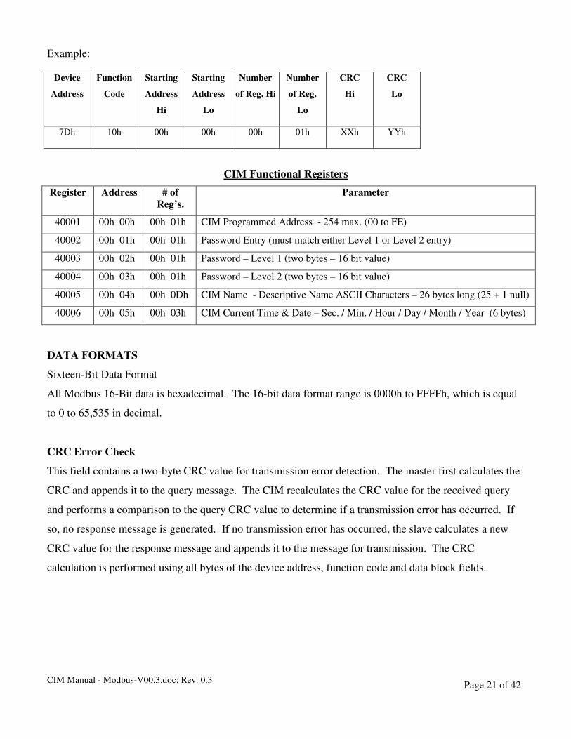
FUNCTION 16 (10h) – Preset Multiple Registers
A preset multiple registers query could address multiple registers in one slave or multiple slave devices.
If the query is broadcast (device address = 0), no response is returned.
Query
A Preset Multiple Register query message requests a register or block of registers to be written. The data
block contains the starting address and the quantity of registers to be written , followed by the Data Block
byte count and data. The CIM will perform the write when the device address is the same as the CIM’s
remote address. A register address on N will write Holding Register N+1.
No data will be written if any of the following exceptions occur.
1. Queries to write to Read Only or unsupported registers result in an error response “Illegal Data
Address”.
2. Queries attempting to write more than (X) registers cause an error response “Illegal Data”
a. X=1 register for CIM address, password entry, setting of passwords
b. X=13 registers for setting CIM name
c. X=3 registers for setting time/date
3. A query to write an unimplemented register will result in an error response “Not Supported”
4. Failure of the CRC check will result in no action including a response.
Example:
Device
Address
Function
Code
Starting
Address
Hi
Starting
Address
Lo
Number
of Reg. Hi
Number
of Reg.
Lo
Byte
Count
Data
Hi
Data
Lo
CRC
Hi
CRC
Lo
7Dh 10h 00h 00h 00h 01h 02h 00h ALh XXh YYh
Note: AL = Address Lo Byte
Response
The response message contains the data queried. The response message echoes the starting address and
the number of registers. There is no response message when the query is a broadcast (device address = 0).
CIM Manual - Modbus-V00.3.doc; Rev. 0.3 Page 21 of 42
Example:
Device
Address
Function
Code
Starting
Address
Hi
Starting
Address
Lo
Number
of Reg. Hi
Number
of Reg.
Lo
CRC
Hi
CRC
Lo
7Dh 10h 00h 00h 00h 01h XXh YYh
CIM Functional Registers
Register Address # of
Reg’s.
Parameter
40001 00h 00h 00h 01h CIM Programmed Address - 254 max. (00 to FE)
40002 00h 01h 00h 01h Password Entry (must match either Level 1 or Level 2 entry)
40003 00h 02h 00h 01h Password – Level 1 (two bytes – 16 bit value)
40004 00h 03h 00h 01h Password – Level 2 (two bytes – 16 bit value)
40005 00h 04h 00h 0Dh CIM Name - Descriptive Name ASCII Characters – 26 bytes long (25 + 1 null)
40006 00h 05h 00h 03h CIM Current Time & Date – Sec. / Min. / Hour / Day / Month / Year (6 bytes)
DATA FORMATS
Sixteen-Bit Data Format
All Modbus 16-Bit data is hexadecimal. The 16-bit data format range is 0000h to FFFFh, which is equal
to 0 to 65,535 in decimal.
CRC Error Check
This field contains a two-byte CRC value for transmission error detection. The master first calculates the
CRC and appends it to the query message. The CIM recalculates the CRC value for the received query
and performs a comparison to the query CRC value to determine if a transmission error has occurred. If
so, no response message is generated. If no transmission error has occurred, the slave calculates a new
CRC value for the response message and appends it to the message for transmission. The CRC
calculation is performed using all bytes of the device address, function code and data block fields.

CIM Manual - Modbus-V00.3.doc; Rev. 0.3 Page 22 of 42
Sessions
As stated a session must be opened before you can read status or control outputs. The ping command is
the only command that works without an opened session. To open a session send the valid password using
the “Enter Password” command. The session will stay opened until 60 seconds after the last valid
command is received or a “Quit” command is sent. To read status a level 1 or level 2 session must be
opened. To control the breaker or modify passwords or the CIM’s address a level 2 session must be
opened.
CIM Manual - Modbus-V00.3.doc; Rev. 0.3 Page 23 of 42
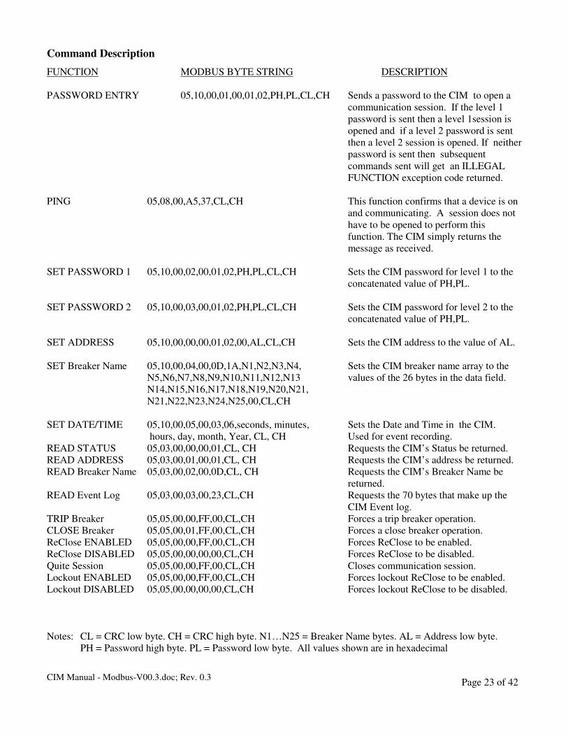
Command Description
FUNCTION MODBUS BYTE STRING DESCRIPTION
PASSWORD ENTRY 05,10,00,01,00,01,02,PH,PL,CL,CH Sends a password to the CIM to open a
communication session. If the level 1
password is sent then a level 1session is
opened and if a level 2 password is sent
then a level 2 session is opened. If neither
password is sent then subsequent
commands sent will get an ILLEGAL
FUNCTION exception code returned.
PING 05,08,00,A5,37,CL,CH This function confirms that a device is on
and communicating. A session does not
have to be opened to perform this
function. The CIM simply returns the
message as received.
SET PASSWORD 1 05,10,00,02,00,01,02,PH,PL,CL,CH Sets the CIM password for level 1 to the
concatenated value of PH,PL.
SET PASSWORD 2 05,10,00,03,00,01,02,PH,PL,CL,CH Sets the CIM password for level 2 to the
concatenated value of PH,PL.
SET ADDRESS 05,10,00,00,00,01,02,00,AL,CL,CH Sets the CIM address to the value of AL.
SET Breaker Name 05,10,00,04,00,0D,1A,N1,N2,N3,N4, Sets the CIM breaker name array to the
N5,N6,N7,N8,N9,N10,N11,N12,N13 values of the 26 bytes in the data field.
N14,N15,N16,N17,N18,N19,N20,N21,
N21,N22,N23,N24,N25,00,CL,CH
SET DATE/TIME 05,10,00,05,00,03,06,seconds, minutes, Sets the Date and Time in the CIM.
hours, day, month, Year, CL, CH Used for event recording.
READ STATUS 05,03,00,00,00,01,CL, CH Requests the CIM’s Status be returned.
READ ADDRESS 05,03,00,01,00,01,CL, CH Requests the CIM’s address be returned.
READ Breaker Name 05,03,00,02,00,0D,CL, CH Requests the CIM’s Breaker Name be
returned.
READ Event Log 05,03,00,03,00,23,CL,CH Requests the 70 bytes that make up the
CIM Event log.
TRIP Breaker 05,05,00,00,FF,00,CL,CH Forces a trip breaker operation.
CLOSE Breaker 05,05,00,01,FF,00,CL,CH Forces a close breaker operation.
ReClose ENABLED 05,05,00,00,FF,00,CL,CH Forces ReClose to be enabled.
ReClose DISABLED 05,05,00,00,00,00,CL,CH Forces ReClose to be disabled.
Quite Session 05,05,00,00,FF,00,CL,CH Closes communication session.
Lockout ENABLED 05,05,00,00,FF,00,CL,CH Forces lockout ReClose to be enabled.
Lockout DISABLED 05,05,00,00,00,00,CL,CH Forces lockout ReClose to be disabled.
Notes: CL = CRC low byte. CH = CRC high byte. N1…N25 = Breaker Name bytes. AL = Address low byte.
PH = Password high byte. PL = Password low byte. All values shown are in hexadecimal
CIM Manual - Modbus-V00.3.doc; Rev. 0.3 Page 24 of 42
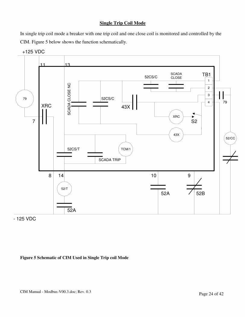
Single Trip Coil Mode
In single trip coil mode a breaker with one trip coil and one close coil is monitored and controlled by the
CIM. Figure 5 below shows the function schematically.
Figure 5 Schematic of CIM Used in Single Trip coil Mode
79
TCM/1
2
1
4
3
SCADA
CLOSE52CS/C
+125 VDC
XRC
S2
52CS/T
SCADA TRIP
52/T
52A
148 10 9
52/CC43X
43X
52CS/C
SC
AD
A C
LO
SE
NC
XRC
- 125 VDC
52B52A
79
7
11 13
TB1
CIM Manual - Modbus-V00.3.doc; Rev. 0.3 Page 25 of 42
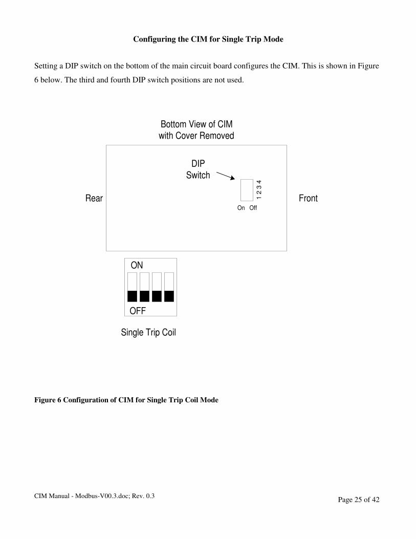
Configuring the CIM for Single Trip Mode
Setting a DIP switch on the bottom of the main circuit board configures the CIM. This is shown in Figure
6 below. The third and fourth DIP switch positions are not used.
Figure 6 Configuration of CIM for Single Trip Coil Mode
ON
OFF
Single Trip Coil
Bottom View of CIMwith Cover Removed
FrontRear
DIP
Switch
On Off
1 2
3 4
CIM Manual - Modbus-V00.3.doc; Rev. 0.3 Page 26 of 42
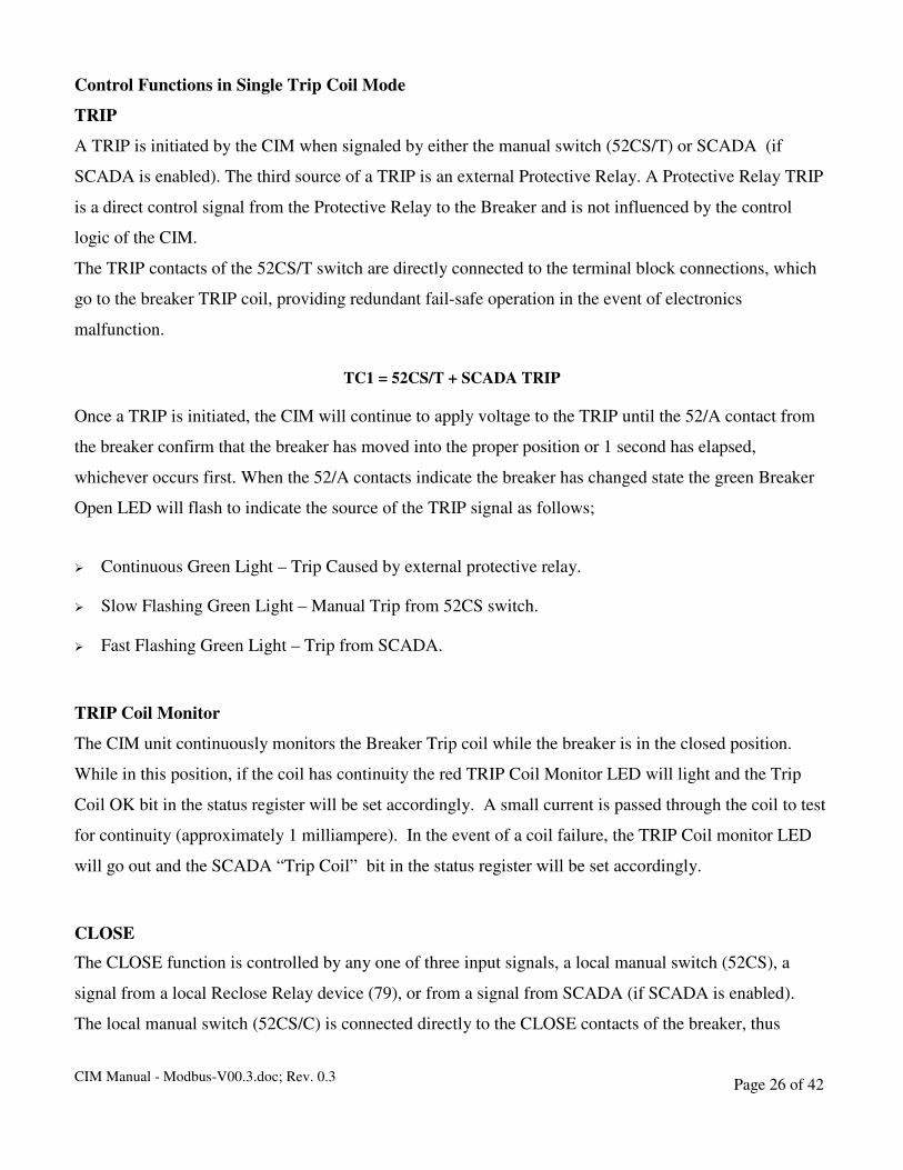
Control Functions in Single Trip Coil Mode
TRIP
A TRIP is initiated by the CIM when signaled by either the manual switch (52CS/T) or SCADA (if
SCADA is enabled). The third source of a TRIP is an external Protective Relay. A Protective Relay TRIP
is a direct control signal from the Protective Relay to the Breaker and is not influenced by the control
logic of the CIM.
The TRIP contacts of the 52CS/T switch are directly connected to the terminal block connections, which
go to the breaker TRIP coil, providing redundant fail-safe operation in the event of electronics
malfunction.
TC1 = 52CS/T + SCADA TRIP
Once a TRIP is initiated, the CIM will continue to apply voltage to the TRIP until the 52/A contact from
the breaker confirm that the breaker has moved into the proper position or 1 second has elapsed,
whichever occurs first. When the 52/A contacts indicate the breaker has changed state the green Breaker
Open LED will flash to indicate the source of the TRIP signal as follows;
� Continuous Green Light – Trip Caused by external protective relay.
� Slow Flashing Green Light – Manual Trip from 52CS switch.
� Fast Flashing Green Light – Trip from SCADA.
TRIP Coil Monitor
The CIM unit continuously monitors the Breaker Trip coil while the breaker is in the closed position.
While in this position, if the coil has continuity the red TRIP Coil Monitor LED will light and the Trip
Coil OK bit in the status register will be set accordingly. A small current is passed through the coil to test
for continuity (approximately 1 milliampere). In the event of a coil failure, the TRIP Coil monitor LED
will go out and the SCADA “Trip Coil” bit in the status register will be set accordingly.
CLOSE
The CLOSE function is controlled by any one of three input signals, a local manual switch (52CS), a
signal from a local Reclose Relay device (79), or from a signal from SCADA (if SCADA is enabled).
The local manual switch (52CS/C) is connected directly to the CLOSE contacts of the breaker, thus
CIM Manual - Modbus-V00.3.doc; Rev. 0.3 Page 27 of 42
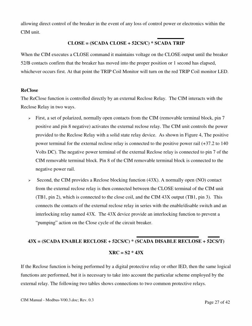
allowing direct control of the breaker in the event of any loss of control power or electronics within the
CIM unit.
CLOSE = (SCADA CLOSE + 52CS/C) * SCADA TRIP
When the CIM executes a CLOSE command it maintains voltage on the CLOSE output until the breaker
52/B contacts confirm that the breaker has moved into the proper position or 1 second has elapsed,
whichever occurs first. At that point the TRIP Coil Monitor will turn on the red TRIP Coil monitor LED.
ReClose
The ReClose function is controlled directly by an external Reclose Relay. The CIM interacts with the
Reclose Relay in two ways.
� First, a set of polarized, normally open contacts from the CIM (removable terminal block, pin 7
positive and pin 8 negative) activates the external reclose relay. The CIM unit controls the power
provided to the Reclose Relay with a solid state relay device. As shown in Figure 4, The positive
power terminal for the external reclose relay is connected to the positive power rail (+37.2 to 140
Volts DC). The negative power terminal of the external Reclose relay is connected to pin 7 of the
CIM removable terminal block. Pin 8 of the CIM removable terminal block is connected to the
negative power rail.
� Second, the CIM provides a Reclose blocking function (43X). A normally open (NO) contact
from the external reclose relay is then connected between the CLOSE terminal of the CIM unit
(TB1, pin 2), which is connected to the close coil, and the CIM 43X output (TB1, pin 3). This
connects the contacts of the external reclose relay in series with the enable/disable switch and an
interlocking relay named 43X. The 43X device provide an interlocking function to prevent a
“pumping” action on the Close cycle of the circuit breaker.
43X = (SCADA ENABLE RECLOSE + 52CS/C) * (SCADA DISABLE RECLOSE + 52CS/T)
XRC = S2 * 43X
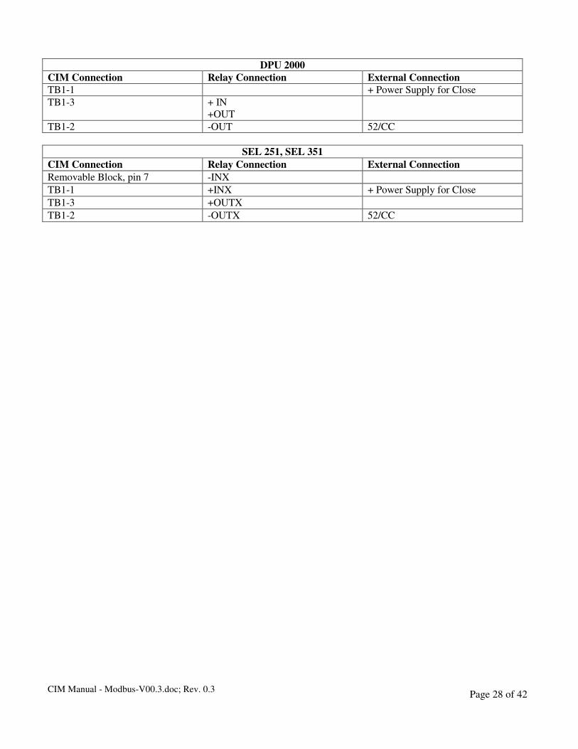
If the Reclose function is being performed by a digital protective relay or other IED, then the same logical
functions are performed, but it is necessary to take into account the particular scheme employed by the
external relay. The following two tables shows connections to two common protective relays.
CIM Manual - Modbus-V00.3.doc; Rev. 0.3 Page 28 of 42
DPU 2000
CIM Connection Relay Connection External Connection
TB1-1 + Power Supply for Close
TB1-3 + IN
+OUT
TB1-2 -OUT 52/CC
SEL 251, SEL 351
CIM Connection Relay Connection External Connection
Removable Block, pin 7 -INX
TB1-1 +INX + Power Supply for Close
TB1-3 +OUTX
TB1-2 -OUTX 52/CC
CIM Manual - Modbus-V00.3.doc; Rev. 0.3 Page 29 of 42
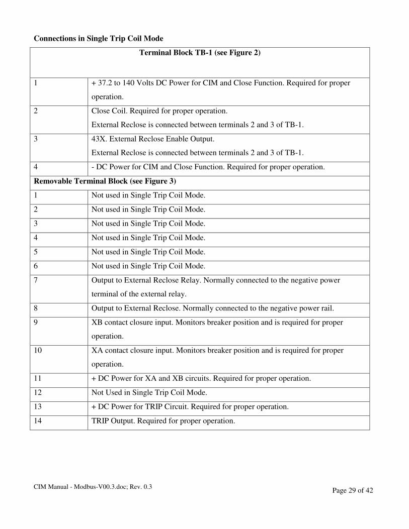
Connections in Single Trip Coil Mode
Terminal Block TB-1 (see Figure 2)
1 + 37.2 to 140 Volts DC Power for CIM and Close Function. Required for proper
operation.
2 Close Coil. Required for proper operation.
External Reclose is connected between terminals 2 and 3 of TB-1.
3 43X. External Reclose Enable Output.
External Reclose is connected between terminals 2 and 3 of TB-1.
4 - DC Power for CIM and Close Function. Required for proper operation.
Removable Terminal Block (see Figure 3)
1 Not used in Single Trip Coil Mode.
2 Not used in Single Trip Coil Mode.
3 Not used in Single Trip Coil Mode.
4 Not used in Single Trip Coil Mode.
5 Not used in Single Trip Coil Mode.
6 Not used in Single Trip Coil Mode.
7 Output to External Reclose Relay. Normally connected to the negative power
terminal of the external relay.
8 Output to External Reclose. Normally connected to the negative power rail.
9 XB contact closure input. Monitors breaker position and is required for proper
operation.
10 XA contact closure input. Monitors breaker position and is required for proper
operation.
11 + DC Power for XA and XB circuits. Required for proper operation.
12 Not Used in Single Trip Coil Mode.
13 + DC Power for TRIP Circuit. Required for proper operation.
14 TRIP Output. Required for proper operation.
CIM Manual - Modbus-V00.3.doc; Rev. 0.3 Page 30 of 42
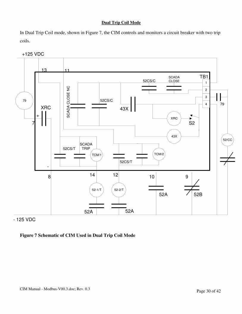
Dual Trip Coil Mode
In Dual Trip Coil mode, shown in Figure 7, the CIM controls and monitors a circuit breaker with two trip
coils.
Figure 7 Schematic of CIM Used in Dual Trip Coil Mode
79
TCM/2
2
1
4
3
SCADA
CLOSE52CS/C
+125 VDC
XRC
S2
52CS/T
SCADATRIP
52-2/T
52A
148 10 9
52/CC43X
43X
52CS/C
SC
AD
A C
LO
SE
NC
XRC
- 125 VDC
52B52A
79
7
1113
TB1
TCM/1
52-1/T
12
52CS/T
52A
+
-

CIM Manual - Modbus-V00.3.doc; Rev. 0.3 Page 31 of 42
Configuring the CIM for Dual Trip Coil Mode
Setting a DIP switch on the bottom of the main circuit board configures the CIM. This is shown in
Figure 8.
Figure 8 Configuring the CIM in Dual Trip Coil Mode
ON
OFF
Dual Trip Coil
Bottom View of CIMwith Cover Removed
FrontRear
DIPSwitch
On Off
1 2
3 4

CIM Manual - Modbus-V00.3.doc; Rev. 0.3 Page 32 of 42
Control Functions in Dual Trip Coil Mode
TRIP
A TRIP is initiated by the CIM when signaled to do so by either the manual switch (52CS/T) or SCADA
(if SCADA is enabled). The third source of a TRIP is an external protective relay. A protective relay
TRIP is a direct control signal from the protective relay to the breaker and is not influenced by the control
logic of the CIM. The TRIP contacts of the 52CS/T switch are directly connected to the terminal block
connections, which go to the breaker TRIP coil, providing redundant fail-safe operation in the event of
electronics malfunction. There are two isolated trip coil outputs. TC1 on the Removable Terminal Block,
pin 12 and TC2 on pin 14.
TC1 = 52CS/T + SCADA TRIP
TC2 = 52CS/T + SCADA TRIP
Once a TRIP is initiated, the CIM will continue to apply voltage to the TRIP outputs (CIM removable
terminal block, pin 12 and pin 14) until the 52/A contact from the breaker confirms that the breaker has
moved into the proper position or 1 second has elapsed, whichever occurs first. When the 52/A contacts
indicate the breaker has changed state the green Breaker Open LED will flash to indicate the source of the
TRIP signal as follows;
� Continuous Green Light – Trip Caused by external protective relay.
� Slow Flashing Green Light – Manual Trip from 52CS switch.
� Fast Flashing Green Light – Trip from SCADA.
CLOSE
The CLOSE function is controlled by any one of three input signals, a local manual switch (52CS/C), a
signal from a local Reclose Relay device (79), or from a signal from SCADA (if SCADA is enabled).
The local manual switch (52CS/C) is connected directly to the CLOSE contacts of the breaker, thus
allowing direct control of the breaker in the event of any loss of control power or electronics within the
CIM unit.
CLOSE = (SCADA CLOSE + 52CS/C) * SCADA TRIP
CIM Manual - Modbus-V00.3.doc; Rev. 0.3 Page 33 of 42
When the CIM executes a CLOSE command it maintains voltage on the CLOSE output until the breaker
52/B contacts confirm that the breaker has moved into the proper position or 1 second has elapsed,
whichever occurs first. At that point the TRIP Coil Monitor will turn on the red TRIP Coil monitor LED.
TRIP Coil Monitor
The CIM unit continuously monitors the Breaker Trip coil while the breaker is in the closed position.
While in this position, if the coil has continuity the red TRIP Coil Monitor LED will light and the Trip
Coil OK bit in the status register will be set accordingly. A small current is passed through the coil to test
for continuity (approximately 1 milli-ampere). In the event of a coil failure, the TRIP Coil monitor LED
will go out and the Trip Coil OK bit in the status register is set accordingly.
CIM Manual - Modbus-V00.3.doc; Rev. 0.3 Page 34 of 42
ReClose
The ReClose function is controlled directly by an external Reclose Relay. The CIM interacts with the
Reclose Relay in two ways.
� First, a set of polarized, normally open contacts from the CIM (removable terminal block, pin 7
positive and pin 8 negative) activates the external reclose relay. The CIM unit controls the power
provided to the Reclose Relay with a solid state relay device. As shown in Figure 6, The positive
power terminal for the external reclose relay is connected to the positive power rail (+37.2 to 140
Volts DC). The negative power terminal of the external Reclose relay is connected to pin 7 of the
CIM removable terminal block. Pin 8 of the CIM removable terminal block is connected to the
negative power rail.
� Second, the CIM provides a Reclose blocking function (43X). A normally open (NO) contact from
the external reclose relay is then connected between the CLOSE terminal of the CIM unit (TB1,
pin 2), which is connected to the close coil, and the CIM 43X output (TB1, pin 3). This connects
the contacts of the external reclose relay in series with the enable/disable switch and an
interlocking relay named 43X. The 43X device provide an interlocking function to prevent a
“pumping” action on the Close cycle of the circuit breaker.
43X = (SCADA ENABLE RECLOSE + 52CS/C) * (SCADA DISABLE RECLOSE + 52CS/T)
XRC = S2 * 43X
If the Reclose function is being performed by a digital protective relay or other IED, then the same logical
functions are performed, but it is necessary to take into account the particular scheme employed by the
external relay. The following two tables shows connections to two common protective relays.
DPU 2000
CIM Connection Relay Connection External Connection
TB1-1 + Power Supply for Close
TB1-3 + IN
+OUT
TB1-2 -OUT 52/CC
SEL 251, SEL 351
CIM Connection Relay Connection External Connection
Removable Block, pin 7 -INX
TB1-1 +INX + Power Supply for Close
TB1-3 +OUTX
TB1-2 -OUTX 52/CC

CIM Manual - Modbus-V00.3.doc; Rev. 0.3 Page 35 of 42
Connections in Dual Trip Coil Mode
Terminal Block TB-1 (see Figure 2)
1 + 37.2 to 140 Volts DC Power for CIM and Close Function. Required for proper
operation.
2 Close Coil. Required for proper operation.
External Reclose is Connected between terminals 2 and 3 of TB-1.
3 43X. External Reclose Enable Output.
External Reclose relay is connected between terminals 2 and 3 of TB-1.
4 - DC Power for CIM and Close Function. Required for proper operation.
Removable Terminal Block (see Figure 3)
1 Not used in Dual Trip Coil Mode.
2 Not used in Dual Trip Coil Mode.
3 Not used in Dual Trip Coil Mode.
4 Not used in Dual Trip Coil Mode.
5 Not used in Dual Trip Coil Mode.
6 Not used in Dual Trip Coil Mode.
7 Output to External Reclose Relay. Normally connected to the negative power
terminal of the external relay.
8 Output to External Reclose. Normally connected to the negative power rail. Pin 8
must be negative relative to pin 7.
9 XB contact closure input. Monitors breaker position and is required for proper
operation.
10 XA contact closure input. Monitors breaker position and is required for proper
operation.
11 + DC Power Trip Coil 2 and XA and XB circuits. Required for proper operation.
12 Trip Coil 2 Output. Required for proper operation
13 + DC Power for TRIP Coil 1. Required for proper operation.
14 TRIP Coil 1 Output. Required for proper operation.
CIM Manual - Modbus-V00.3.doc; Rev. 0.3 Page 36 of 42
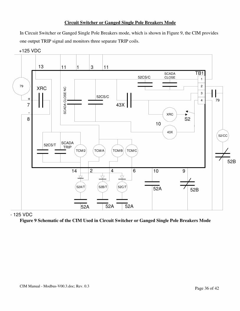
Circuit Switcher or Ganged Single Pole Breakers Mode
In Circuit Switcher or Ganged Single Pole Breakers mode, which is shown in Figure 9, the CIM provides
one output TRIP signal and monitors three separate TRIP coils.
Figure 9 Schematic of the CIM Used in Circuit Switcher or Ganged Single Pole Breakers Mode
79
TCM/A
2
1
4
3
SCADA
CLOSE52CS/C
+125 VDC
XRC
S2
SCADATRIP
52B/T
52A
14
810
9
52/CC43X
43X
52CS/C
SC
AD
A C
LO
SE
NC
XRC
- 125 VDC
79
7
1113
TB1
TCM/2
52A/T
2
52CS/T
52A
52C/T
TCM/B TCM/C
6
52A
4
52B52A
10
1 3 11
52B
+
-

CIM Manual - Modbus-V00.3.doc; Rev. 0.3 Page 37 of 42
Configuring the CIM for Circuit Switcher or Ganged Single Pole Breakers Mode
Setting a DIP switch on the bottom of the main circuit board configures the CIM. This is shown in Figure
10. The third and fourth DIP switches are not used.
Figure 10 Configuring the CIM in Circuit Switcher or Ganged Single Pole Breakers Mode
Bottom View of CIM
with Cover Removed
FrontRear
DIP
Switch
On Off
1 2
3 4
ON
OFF
Triple Trip Coil

CIM Manual - Modbus-V00.3.doc; Rev. 0.3 Page 38 of 42
Control Functions in Circuit Switcher or Ganged Single Pole Breakers Mode
TRIP
A TRIP is initiated by the CIM when signaled to do so by either the manual switch (52CS/T) or SCADA (if
SCADA is enabled). The third source of a TRIP is an external protective relay. A protective relay TRIP is a direct
control signal from the protective relay to the breaker and is not influenced by the control logic of the CIM. The
TRIP contacts of the 52CS/T switch are directly connected to the terminal block connections, which go to the
breaker TRIP coil, providing redundant fail-safe operation in the event of electronics malfunction. In Circuit
Switcher mode a single TRIP signal is connected through external diodes to three trip coils. The diodes are
necessary in order TRIP coil monitoring to work correctly.
TC1 = 52CS/T + SCADA TRIP
Once a TRIP is initiated, the CIM will continue to apply voltage to the TRIP` output (CIM removable
terminal block, pin 14) until the 52/A contact from the breaker confirm that the breaker has moved into
the proper position or 1second has elapsed whichever occurs first. When the 52/A contacts indicate the
breaker has changed state the green Breaker Open LED will flash to indicate the source of the TRIP signal
as follows;
Continuous Green Light – Trip Caused by external protective relay.
Slow Flashing Green Light – Manual Trip from 52CS switch.
Fast Flashing Green Light – Trip from SCADA.
TRIP Coil Monitor
The CIM unit continuously monitors the Breaker Trip coil while the breaker is in the closed position.
While in this position, if the coil has continuity the red TRIP Coil Monitor LED will light and the
SCADA output XTM will be open. A small current is passed through the coil to test for continuity
(approximately 1 milliampere). In the event of a coil failure, the TRIP Coil monitor LED will go out and
the Coil OK bit in the status register will be set accordingly.
CLOSE
The CLOSE function is controlled by any one of three input signals, a local manual switch (52CS), a
signal from a local Reclose Relay device (79), or from a signal from SCADA (if SCADA is enabled).
The local manual switch (52CS/C) is connected directly to the CLOSE contacts of the breaker, thus

CIM Manual - Modbus-V00.3.doc; Rev. 0.3 Page 39 of 42
allowing direct control of the breaker in the event of any loss of control power or electronics within the
CIM unit.
CLOSE = (SCADA CLOSE + 52CS/C) * SCADA TRIP
When the CIM executes a CLOSE command it maintains voltage on the CLOSE output until the breaker
52/B contacts confirm that the breaker has moved into the proper position or 1 second has elapsed,
whichever occurs first. At that point the TRIP Coil Monitor will turn on the red TRIP Coil monitor LED
and the XA and XB bits in the status word are set accordingly.
ReClose
The ReClose function is controlled directly by an external Reclose Relay. The CIM interacts with the
Reclose Relay in two ways.
� First, a set of polarized, normally open contacts from the CIM (removable terminal block, pin 7
positive and pin 8 negative) activates the external reclose relay. The CIM unit controls the power
provided to the Reclose Relay with a solid state relay device. As shown in Figure 8, The positive
power terminal for the external reclose relay is connected to the positive power rail (+37.2 to 140
Volts DC). The negative power terminal of the external Reclose relay is connected to pin 7 of the
CIM removable terminal block. Pin 8 of the CIM removable terminal block is connected to the
negative power rail.
� Second, the CIM provides a Reclose blocking function (43X). A normally open (NO) contact from
the external reclose relay is then connected between the CLOSE terminal of the CIM unit (TB1,
pin 2), which is connected to the close coil, and the CIM 43X output (TB1, pin 3). This connects
the contacts of the external reclose relay in series with the enable/disable switch and an
interlocking relay named 43X. The 43X device provide an interlocking function to prevent a
“pumping” action on the Close cycle of the circuit breaker.
43X = (SCADA ENABLE RECLOSE + 52CS/C) * (SCADA DISABLE RECLOSE + 52CS/T)
XRC = S2 * 43X
CIM Manual - Modbus-V00.3.doc; Rev. 0.3 Page 40 of 42
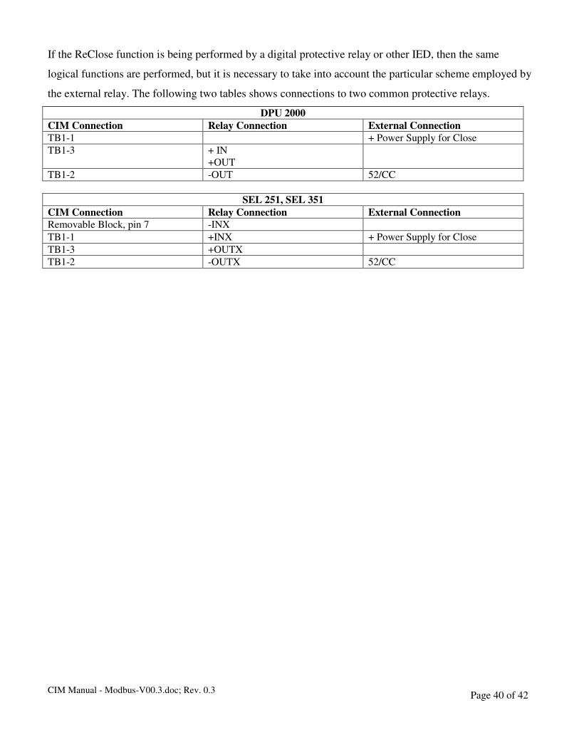
If the ReClose function is being performed by a digital protective relay or other IED, then the same
logical functions are performed, but it is necessary to take into account the particular scheme employed by
the external relay. The following two tables shows connections to two common protective relays.
DPU 2000
CIM Connection Relay Connection External Connection
TB1-1 + Power Supply for Close
TB1-3 + IN
+OUT
TB1-2 -OUT 52/CC
SEL 251, SEL 351
CIM Connection Relay Connection External Connection
Removable Block, pin 7 -INX
TB1-1 +INX + Power Supply for Close
TB1-3 +OUTX
TB1-2 -OUTX 52/CC

CIM Manual - Modbus-V00.3.doc; Rev. 0.3 Page 41 of 42
Connections in Circuit Switcher of Ganged Single Pole Breakers Mode
Terminal Block TB-1 (see Figure 2)
1 + 37.2 to 140 Volts DC Power for CIM and Close Function. Required for proper operation.
2 Close Coil. Required for proper operation.
External Reclose is connected between terminals 2 and 3 of TB-1.
3 43X. External Reclose Enable Output.
External ReClose is connected between terminals 2 and 3 of TB-1.
4 - DC Power for CIM and Close Function. Required for proper operation.
Removable Terminal Block (see Figure 3)
1 + DC Power for TRIP Coil Monitor A. Required for proper operation.
2 TRIP Coil Monitor A input. Normally connected to TRIP Coil A. Required for proper operation.
3 + DC Power for TRIP Coil Monitor B. Required for proper operation.
4 TRIP Coil Monitor A input. Normally connected to TRIP Coil B. Required for proper operation
5 + DC Power for TRIP Coil Monitor C. Required for proper operation.
6 TRIP Coil Monitor A input. Normally connected to TRIP Coil C. Required for proper operation
7 Output to External Reclose Relay. Normally connected to negative power terminal of an external
relay.
8 Output to External Reclose. Normally connected to the negative power rail.
9 XB contact closure input. Monitors breaker position and is required for proper operation.
10 XA contact closure input. Monitors breaker position and is required for proper operation.
11 + DC Power for XA and XB circuits. Required for proper operation.
12 Not used in Circuit Switcher mode.
13 + DC Power for TRIP Coil 1. Required for proper operation.
14 TRIP Coil 1 Output. Required for proper operation.

CIM Manual - Modbus-V00.3.doc; Rev. 0.3 Page 42 of 42
Specifications and Tests
Operating Voltage 38 to 140 V DC @ 100 milli-Amps
TRIP Contact Ratings
140 VDC maximum
0 to 0.5 seconds – 20 A
< 1second – 15 A
< 1 minute – 1 A
Continuous – 0.5 A
CLOSE/Reclose Contact Ratings 140 VDC maximum
0 to 1 second – 30 A
< 1 minute – 3 A
Continuous – 1.5 A
SCADA RS 485
External ReClose Output 140 V maximum - 1 A maximum
Ambient Temperature Rating -20 deg. C to +55 deg. C
Surge Withstand Capability Per IEEE C37.90.1 - 2500 V Oscillatory Surge
5000 V Fast Transient
EMI/RFI (Radio Frequency Immunity) Per IEEE C37.90.2
Dielectric Withstand Voltage 1500 VDC for 60 seconds
Tested Life Under Rated Load 10,000 Operations
Environmental Testing 80 C for 120 hours 40C for 96 hours at 90 to 95% RH