ciciso wl connectivity troubleshooting
TRANSCRIPT

Troubleshooting Connectivity in a Wireless LANNetwork
Document ID: 8117
Refer to the Cisco Wireless Software Center (registered customers only)in order to get Cisco Aironet drivers, firmware and utility software.
Contents
IntroductionPrerequisites Requirements Components Used ConventionsBasic Connectivity Issues Console Connection Cable Radio Power Optimization Radio Interference IP Address Assignment Effect of Loopback Interfaces on APs No Image in AP Flash Booting Issues with the AP Power Issue with the AP Use of Nonoverlapping Channels IOS UpgradeClient Adapter Resource Conflict Indicator LEDs Verify Client CommunicationsAccess Points Root Mode Indicator LEDs SSID VLAN in a Multi−SSID Configuration WEP Keys Reset Firewall Is Enabled on the Client Configuration of Data Rates on the AP Radio Configuration of Radio Preambles Antenna SettingsBridge Indicator LEDs SSID WEP Keys Line of Sight and Fresnel Zone Spanning Tree ProtocolRelated Information

Introduction
This document helps identify and troubleshoot common connectivity problems in configuration, interference,and cable in a wireless network.
Note: Cisco Aironet equipment operates best when you load all components with the most current version ofthe software. Upgrade to the latest versions of the software early in the troubleshooting process.
You can download the latest software and drivers from the Cisco Wireless Software Center (registeredcustomers only) .
This document complements the information in Fixing a Broken Wireless LAN Connection.
Prerequisites
Requirements
There are no specific prerequisites for this document.
Components Used
This document is not restricted to specific software and hardware versions.
Conventions
Refer to Cisco Technical Tips Conventions for more information on document conventions.
Basic Connectivity Issues
Console Connection
Use a straight−through DB−9 male/female cable for console connection.
In a terminal program like Microsoft HyperTerminal, set the session to:
9600 baud• 8 data bits• No parity• 1 stop bit• Xon/Xoff flow control
Note: If the flow control Xon/Xoff does not work, try to use the flow control None.
•
Cable
If you have intermittent connectivity or connectivity with errors, there is a possibility that the cable length isgreater than the recommended Ethernet segment length. Do not exceed the Ethernet cable length that isrecommended in this table:
Cable TypeLength

Coax 10BASE−2185 meters/607 feet
Category 5 10BASE−T100 meters/328 feet
If the distance from the switch exceeds the recommended segment length, use a fiber or a wireless hop, suchas a repeater.
Interference occurs when you run a network cable near high−power equipment. This interference is especiallycommon when you run the cables in warehouses and factories.
When you have interference because of cable length, and a cable tester shows a positive result, use the cabletester only to find a break in the cable. In order to verify the presence of a cable problem, test the connectionto the access point (AP) or bridge with a shorter cable. Then, verify if the problem is still there.
Radio Power Optimization
When you install the AP and the clients associated to it are too close, sometimes the clients disconnect fromthe AP. This problem can be solved by these two methods:
Keep the clients away from the AP.• Reduce the power of the AP.•
Radio Interference
You must conduct a site survey in order to install a wireless network. Conduct the site survey on the actualsite under normal operating conditions with all inventory present. Such a survey is critical because the radiofrequency (RF) behavior varies with the physical properties of the site, and you cannot predict the behavioraccurately without a site survey. You can face intermittent connectivity at certain areas and during certainenvironmental conditions. An example is when a wooden roof is wet after a rain. In this case, perhaps a sitesurvey was not done, or a bad site survey did not consider these factors.
If you use a client adapter on a PC with the Aironet Client Utility (ACU) or the Aironet Desktop Utility(ADU), in order to check the signal strength, run the Site Survey option in ACU. Remember that constructionmaterials, such as steel and wood, absorb RF energy as do objects with water content. Consider interferencefrom devices such as microwave ovens and cordless phones when you place the APs.
This window is an example of the signal strength test:

Perform the carrier test in order to see activity in the RF spectrum. The carrier test is available on bridges. Thetest enables you to view the radio spectrum. This example shows the carrier test on the BR500:
The numbers 12, 17, and so on represent the 11 frequencies that the bridge uses. For example, 12 representsthe frequency 2412 MHz. The asterisks (*) indicate the activity on each frequency. Whenever possible,choose the frequency with the least activity in order to reduce chances of interference.

IP Address Assignment
If you cannot ping the AP or the bridge, check the IP addresses that are assigned to the AP, bridge, and clientadapter. Make sure that they are in the same subnet.
For example, if the IP address of the AP is 10.12.60.5 with a mask of 255.255.255.0, verfiy that the IP addressof the client adapter is similar to 10.12.60.X with a mask of 255.255.255.0. Remember that the AP and thebridge are Layer 2 devices. If you need two or more networks, make sure you have a router on the network.
Refer to the IP Subnet Calculator (registered customers only) tool for more help with IP addresses and thedesign of subnets.
Effect of Loopback Interfaces on APs
Aironet APs and bridges do not support the configuration of loopback interfaces. Even though thecommand−line interface (CLI) allows you to create a loopback interface, avoid the configuration of loopbackinterfaces on APs and bridges. The reason is that a loopback interface configuration can generate an Inter−APProtocol General Information (IAPP GENINFO) storm on your network, which can result in high CPUutilization on the AP. This can slow down the performance of the AP drastically and, in some cases, disruptnetwork traffic completely. The configuration of loopback interfaces on APs or bridges can also causememory allocation failures.
Refer to the Access Points Do Not Support Loopback Interface section of Release Notes for Cisco AironetAccess Points for Cisco IOS Release 12.3(7)JA2 for more information.
No Image in AP Flash
In some instances, if the AP flash is completely erased, the AP does not have a Cisco IOS® image to boot andgets stuck inap: prompt mode. In order to recover the AP in this situation, reload a new Cisco IOS image onthe AP. Refer to the instructions in the Using the CLI section of Troubleshooting (Cisco IOS SoftwareConfiguration Guide for Aironet APs 12.3(7)JA).
Booting Issues with the AP
In some cases, the AP fails to boot completely. This failure can happen if the firmware on the AP is corrupt.In order to resolve this issue, reinstall the firmware on the AP. You can reload the AP image in order toreinstall the firmware. Refer to the instructions in the Using the CLI section of Troubleshooting (Cisco IOSSoftware Configuration Guide for Aironet APs 12.3(7)JA) in order to reload the firmware.
Power Issue with the AP
When an AP uses a power injector as the power source, in some cases, the AP displays this error message:
%CDP_PD−2−POWER_LOW: All radios disabled − LOW_POWER_CLASSIC inline
This message indicates that the AP is in low−power mode with all radios disabled and detects a Cisco switchthat is unable to supply sufficient power to the AP. Even though the power injector, which can providesufficient power, is connected with the AP, the AP still displays a LOW POWER error message and disablesthe radios. Therefore, the AP remains in low−power mode.
One possible reason for this issue might be that the AP supports the Intelligent Power Management feature.The Intelligent Power Management feature uses Cisco Discovery Protocol (CDP) to allow powered devices,such as an AP, to negotiate with a Cisco switch for sufficient power. The AP supports the Intelligent Power

Management feature. As a result of the power negotiations, the AP either enters full−power mode or remainsin low−power mode with the radios disabled.
In this case, the AP might be connected to a switch which cannot provide the necessary power to the AP.Therefore, even though the power injector is connected to the AP that uses this Intelligent Power managementfeature, it gives priority to the CDP information to identify whether or not the switch can provide the power.Once the AP knows, via CDP message, that the switch does not provide sufficient power, it disables the radiosand remains in low−power mode.
The workaround to this issue is to tell the AP to ignore the CDP information for power. You can perform thisby telnetting into the APs. Issue these commands to enable the APs to use the power injector:
power inline negotiation prestandard source• power inline negotiation injector H.H.H•
The power inline negotiation command configures the Cisco Aironet 1130AG or 1240AG Series AP tooperate with a later version of switch software that does not support Cisco Intelligent Power Managementpower negotiations.
The prestandard source portion of the command specifies that the Cisco switch runs a later version ofsoftware that does not support Intelligent Power Management negotiations, but is able to supply sufficientpower to the AP.
The injector H.H.H portion of the command specifies that a power injector supplies power to the AP, and thatthe AP connects to a new switch port with the indicated MAC address (H.H.H). Enter the MAC address (inxxxx.xxxx.xxxx hexadecimal format) of the new switch port where the power injector is connected.
Note: This command should only be used when you move an AP and power injector to a different switch port.
The AP can be powered from the 48−VDC power module or from an inline power source. The AP supportsthese features for inline power sources:
IEEE 802.3af power standard• Cisco prestandard Power over Ethernet (PoE) protocol• Cisco Intelligent Power Management•
For full operation, the AP requires 12.95 W of power. The power module and Aironet power injectors are ableto supply the required power for full operation, but some inline power sources are not able to supply 12.95 W.Also, some high−power inline power sources cannot provide 12.95 W of power to all ports at the same time.
Use of Nonoverlapping Channels
When you have multiple APs in a wireless LAN (WLAN), ensure that the channels that the adjacent APs useare nonoverlapping. Nonoverlapping channels are frequency bands that do not have a frequency that iscommon to the other channels. For example, in the 2.4−GHz range, there are three channels that do notoverlap (channels 1, 6, and 11). Therefore, when you deploy a secondary AP in order to extend the radiocoverage, you can use:
Channel 1 for the first AP• Channel 6 for the next adjacent AP• Channel 11 for the third AP•
Then you can start with channel 1.

If you use channels that overlap, RF interference can occur. This leads to connectivity issues and results inpoor throughput. Refer to Troubleshooting Problems Affecting Radio Frequency Communication for moreinformation on RF interference.
IOS Upgrade
When you upgrade Cisco IOS on an AP from a previous version to 12.3(7)JA3, the most common problem isthat the client does not authenticate properly. This is because the service set identifier (SSID) is no longer onthe radio interface. The first step is to reconfigure the SSID, then remove the Encryption. If it still does notwork, then reconfigure the AP from scratch. Complete these steps:
Choose SECURITY > Encryption Manager.1. Click None and then Apply.2. Go to the SSID Manager, highlight the SSID SSID_Name and choose <NO ADDITION>.3. From the Open Authentication menu, scroll down and click Apply.
Once you have applied these changes, you can test with the client adapter. If the problem still exists,then it is better to start from scratch.
4.
Complete these steps in order to reset the AP back to default:
Choose System Software > System Configuration.a. Click Reset to Defaults (Except IP).
Once it reboots, you can reconfigure it again and test with the client adapter.
b.
5.
Client Adapter
Resource Conflict
If the client adapter card does not communicate, determine if there are any resource conflicts with otherdevices. Make sure that the card is set at interrupt request (IRQ) levels that other devices do not use.Microsoft Windows 95, 98, ME, and 2000 are plug and play, therefore no resource conflicts should exist.
If a conflict does exist, go to the Windows Device Manager Properties window and uncheck the UseAutomatic Settings check box. Enter the IRQ and I/O address manually. If there is a resource conflict, youmust manually set Windows NT, as the procedure in this section explains.
Note: You can also choose to disable the IR port with use of the Windows Device Manager.
Complete these steps in order to identify the free resource in Windows NT:
Choose Start > Programs > Administrative Tools (Common) > Windows NT Diagnostics.1. Click the Resources tab in the Windows NT Diagnostics window.2. Note the IRQ column and check which IRQ numbers are not listed in the Resources window.3. Choose I/O Port in the Resources window.4. Note the Address column and make note of several different open addresses in the Resources window.
The card needs 64 contiguous I/O addresses, for example, 0100 through 013f hexadecimal.
5.
Complete these steps in order to set the correct values in Windows NT:
Choose Start > Settings > Control Panel.1. Double−click the Network icon in the Control Panel window.2.

Click the Adapters tab in the Network window.3. Choose Aironet Adapter in the Adapters panel.4. Click Properties.5. Choose Interrupt in the Property column panel in the Adapter Setup window.
In the Value column, select an IRQ value that is not listed in the Resources tab of the Windows NTDiagnostics window.
6.
Choose the I/O Base Address in the Property column panel in the Adapter Setup window.
In the Value column, select an I/O address that is not listed in the Resources window of the WindowsNT Diagnostics window.
7.
Click OK in the Adapter Setup window, click OK in the Network window, and then close all openwindows and do an orderly shutdown of Windows.
If the client adapter still shows errors, try another I/O address. Windows NT 4.0 does not alwaysreport used resources. It can report that a resource is available when it is not.
8.
Indicator LEDs
Check the status of the Aironet 340 Series Client Adapter LED in order to verify if it matches the deviceconfiguration.
The client adapter shows messages and error conditions through two LEDs:
Link Integrity/Power LED (green)�This LED lights when the client adapter receives power andblinks slowly when the adapter is linked with the network.
•
Link Activity LED (amber)�This LED blinks when the client adapter receives or transmits data andblinks quickly to indicate an error condition.
•
Refer to this table in order to determine the condition that a specific LED message indicates:
Green LED AmberLED
Condition
OffOff
Client adapter does notreceive power or an erroroccurs.
Blinks quickly Blinksquickly
Power is on, self test is OK,and client adapter scans for anetwork.
Blinks slowly Blinksquickly
Client adapter associates to anAP.
Continuously on orblinks slowly
BlinksClient adapter transmits orreceives data while itassociates to an AP.
Off Blinksquickly
Client adapter is in powersave mode.
On Blinksquickly
Client adapter is in ad−hocmode.
OffOn Driver is installed incorrectly.
Off Blinks in apattern
Indicates an error condition.
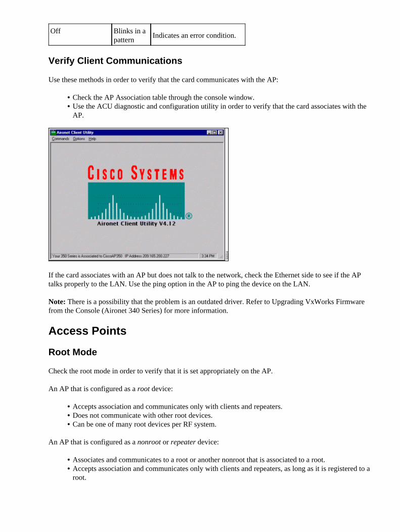
Verify Client Communications
Use these methods in order to verify that the card communicates with the AP:
Check the AP Association table through the console window.• Use the ACU diagnostic and configuration utility in order to verify that the card associates with theAP.
•
If the card associates with an AP but does not talk to the network, check the Ethernet side to see if the APtalks properly to the LAN. Use the ping option in the AP to ping the device on the LAN.
Note: There is a possibility that the problem is an outdated driver. Refer to Upgrading VxWorks Firmwarefrom the Console (Aironet 340 Series) for more information.
Access Points
Root Mode
Check the root mode in order to verify that it is set appropriately on the AP.
An AP that is configured as a root device:
Accepts association and communicates only with clients and repeaters.• Does not communicate with other root devices.• Can be one of many root devices per RF system.•
An AP that is configured as a nonroot or repeater device:
Associates and communicates to a root or another nonroot that is associated to a root.• Accepts association and communicates only with clients and repeaters, as long as it is registered to aroot.
•

Indicator LEDs
The indicator lights of the Aironet 340 Series AP have these purposes:
The Ethernet indicator signals traffic on the wired LAN or Ethernet infrastructure. This indicatorblinks green when a packet is received or transmitted over the Ethernet infrastructure.
•
The status indicator signals operational status. This indicator blinks green in order to indicate that theAP operates normally but does not associate with any wireless devices. Steady green indicates that theAP associates with a wireless client.
A repeater AP that blinks 50 percent on and 50 percent off indicates that it does not associate with theroot AP. A repeater AP that blinks 7/8 on and 1/8 off indicates that it associates with the root AP, butno client devices associate with the repeater. A repeater AP that blinks green steadily indicates that itassociates with the root AP, and that client devices associate with that repeater.
•
The radio indicator blinks green in order to indicate radio traffic activity. The light is normally off,but it blinks green whenever a packet is received or transmitted over the AP radio.
•
This table helps you determine the condition that a specific LED message indicates:
MessageType Radio
IndicatorStatus
IndicatorInfrastructure
IndicatorMeaning
Associationstatus
Steadygreen
At least onewireless clientdevice associateswith the unit.
Blinksgreen
Operational
Blinksgreen Steady
green
No client devicesassociate. Checkthe SSID1 andWEP2 settings ofthe unit.
Steadygreen
Blinks greenTransmits/receivespackets overEthernet.
Blinksamber Steady
green
Maximum retriesor buffer fulloccur on the radio.
Error/warningSteadygreen
Blinks amberThere aretransmit/receiveerrors.
Blinks redEthernet cabledisconnects.
Blinksamber
This is a generalwarning.
Failure Steadyred
Steadyred
Steady red Indicates afirmware failure.Disconnect powerfrom the unit and

reapply power.
Firmwareupgrade Steady
redThe unit loadsnew firmware.
1 SSID = service set identifier.
2 WEP = Wired Equivalent Privacy.
SSID
Wireless clients that attempt to associate with the AP must use the same SSID as the AP. The default SSID istsunami.
Allow "Broadcast" SSID to Associate?
The Allow "Broadcast" SSID to Associate? setting allows you to choose whether devices that do not specifyan SSID are allowed to associate with the AP. Devices that do not specify an SSID "broadcast" in search of anAP with which to associate.
Yes�This is the default setting. It allows devices that do not specify an SSID to associate with the AP.• No�Devices that do not specify an SSID are not allowed to associate with the AP. The SSID that theclient device uses must match the SSID of the AP.
•
If you have communication problems and the device is set to No, change the setting to Yes and see if thedevice can communicate. Leave the setting as Yes for the duration of this troubleshoot.
Usage of the mobility network−id Command
Connectivity problems in a WLAN network can occur if you use the mobility network−id commandincorrectly. You use the mobility network−id command in order to configure Layer 3 mobility in a wirelessnetwork. This command is meant to be used when the AP participates in a wireless domain services (WDS)infrastructure with a WLAN services module (WLSM) (that acts as the WDS device) where there is Layer 3mobility.
Therefore, when an AP is configured as a WDS device, do not use the mobility network−id command.
If you use this command incorrectly, connectivity problems in the WLAN network result, such as:
Clients do not get IP addresses from the DHCP.• Clients cannot associate with the AP.• A wireless phone cannot be authenticated when you have a voice−over WLAN deployment.•
VLAN in a Multi−SSID Configuration
In some cases, when you configure VLANs in a multi−SSID setup, the interfaces on the AP and switch showthat trunking is up and running. However, the Layer 3 interface on the switch cannot ping the AP. Also, theAP cannot ping the switch interface. In order to resolve this issue, issue the bridge−group 1 command underthe radio interface and the Fast Ethernet interface. This command ties the native VLAN to the bvi interface.Then, issue the bridge 1 router ip command in the global configuration mode.

WEP Keys
You must set up the WEP key that you use to transmit data in exactly the same way on your AP and on anywireless devices that the AP associates.
For example, if you set WEP Key 3 on your WLAN adapter to 0987654321 and select this key as the transmitkey, you must also set WEP Key 3 on the AP to the same value. However, the AP does not need to use Key 3as the transmit key. Check the WEP key.
These are some points to remember about WEP keys:
Open authentication allows authorization and associations with or without a WEP key.• If a WEP key is used, both the client and the AP must have WEP keys that match.• If one of these devices does not have a WEP key that matches, data traffic cannot be passed becausethe data is encrypted.
•
Do not use the WEP key to verify that the problem persists. Leave the WEP key inactive until you identify theconnectivity problem.
Reset
Sometimes the problem with misconfigured SSIDs or WEP keys is difficult to identify. For example, theWEP key can have one digit that is mistyped. In order to overcome such problems, note the configurationsand reenter them after a reset.
Firewall Is Enabled on the Client
If you try to access the AP via a PC client with a firewall enabled, you might have to disable the firewall.Otherwise, you cannot log in to the AP.
Configuration of Data Rates on the AP Radio
The data rate setting on the AP radio defines the rate at which the AP transmits information. Radio data ratesare expressed in Mbps.
On APs, you can set the data rates to any one of these three states:
Basic�This allows transmission at this rate for all packets, both unicast and multicast. You must setthe data rates of at least one of the wireless devices to Basic. In the GUI, this state is called Require.
•
Enabled�The wireless device transmits only unicast packets at this rate. Multicast packets are sent atone of the data rates that are set to Basic.
•
Disabled�The wireless device does not transmit data at this rate.•
The wireless device always attempts to transmit at the highest data rate that is set to Basic. If there areobstacles or interference, the wireless device steps down to the highest rate that allows data transmission.
These data rates are supported on an IEEE 802.11b, 2.4 GHz radio:
1 Mbps• 2 Mbps• 5.5 Mbps• 11 Mbps•

These data rates are supported on an IEEE 802.11g, 2.4 GHz radio:
1 Mbps• 2 Mbps• 5.5 Mbps• 6 Mbps• 9 Mbps• 11 Mbps• 12 Mbps• 18 Mbps• 24 Mbps• 36 Mbps• 48 Mbps• 54 Mbps•
These data rates are supported on an IEEE 802.11a, 5 GHz radio:
6 Mbps• 9 Mbps• 12 Mbps• 18 Mbps• 24 Mbps• 36 Mbps• 48 Mbps• 54 Mbps•
When you configure the AP radio, you must consider the type of clients that are present in the wirelessnetwork. If the AP has an 802.11g radio and the WLAN has only 802.11g clients, you can set one or moredata rates to Basic and all other data rates to Enabled.
However, if you have a mixed environment of both 802.11b and 802.11g clients in a WLAN network, youmust ensure that only the rates that 802.11b supports are set to Basic (or Require in GUI). If data rates that the802.11b radio does not support (such as 12 Mbps) are set to Basic on the AP radio, the 802.11b clients are notable to associate to the AP.
Alternatively, you can configure the AP radio to select data rates on the basis of range or throughput. Whenyou configure the AP radio to select data rates for range, the AP sets the lowest data rate to Basic and theother rates to Enabled. In this way, the AP can cover a wider area. However, the data rate comes down as thedistance from the AP to the client increases. If you configure the AP radio for throughput, the AP sets all datarates to Basic. This configuration ensures a consistent throughput throughout the coverage area.
Refer to the Configuring Radio Data Rates section of Configuring Radio Settings for more information onhow to configure the data rates on the AP radio.
Configuration of Radio Preambles
The radio preamble, which is sometimes called a header, is a section of data at the head of a packet thatcontains information that the wireless devices (which include wireless clients) need when they send andreceive packets. Radio preambles can be either short preambles or long preambles.
If you configure the radio preambles incorrectly, the client is not able to associate with the wireless AP. Theradio preamble configuration is dependent on the client cards that are used in the wireless network. AironetWLAN Client Adapters support short preambles. Early models of the Aironet WLAN Adapter (PC4800 andPC4800A) require long preambles. If these client devices do not associate to the wireless devices, you should

not use short preambles.
Refer to the Disabling and Enabling Short Radio Preambles section of Configuring Radio Settings forinformation on how to configure the radio preambles on the AP.
Antenna Settings
The dual antenna ports on the AP are used for diversity. You only need to connect an antenna to the primary(right) port for radio operations. The left port is not used independently of the primary port. Once you connectthe external antenna to either the right or left antenna port of the AP, you must configure the AP to transmitand receive on that specific port. The default is for antenna diversity. This helps the radio compensate forerrors due to RF interference. Any antenna adapters used must have the matching impedance of the antennacable and the AP.
Bridge
There can only be one bridge with the root on in an RF network. Set all other bridges to root off.
Indicator LEDs
The indicator lights of an Aironet 340 Series Bridge have these purposes:
The Ethernet indicator signals traffic on the wired LAN or Ethernet infrastructure. This indicatorblinks green when a packet is received or transmitted over the Ethernet infrastructure.
•
The status indicator signals operational status. This indicator blinks green in order to indicate that thebridge operates normally but does not communicate with an AP. Steady green indicates that thebridge communicates with an AP.
•
The radio indicator blinks green in order to indicate radio traffic activity. The light is normally off,but it blinks green whenever a packet is received or transmitted over the bridge radio.
•
This table helps you determine the condition that a specific LED message indicates:
MessageType Radio
IndicatorStatus
IndicatorInfrastructure
IndicatorMeaning
Associationstatus
Steadygreen
Linked to theWLAN.
Blinksgreen
Not linked to theWLAN. Check theSSID and WEPsettings of theunit.
Operational Blinksgreen Steady
greenTransmits/receivesradio packets.
Steadygreen
Blinks greenTransmits/receivespackets.
Blinksamber
Steadygreen
Maximum retriesor buffer fulloccur on the radio.The AP withwhich the bridge

communicatesmight beoverloaded, orradio receptionmight be poor.Change the SSIDof the bridge inorder tocommunicate withanother AP, orreposition thebridge in order toimproveconnectivity.
Error/warningSteadygreen
Blinks amberThere aretransmit/receiveerrors.
Blinks redEthernet cabledisconnects.
Blinksamber
This is a generalwarning.
Failure Steadyred
Steadyred
Steady red
Indicates afirmware failure.Disconnect powerfrom the unit andreapply power.
Firmwareupgrade Steady
redThe unit loadsnew firmware.
SSID
The SSID of the bridge must match the SSID of an Aironet AP on your WLAN. The AP must be within radiorange of the bridge.
WEP Keys
You must set up the WEP key that you use to transmit data in exactly the same way on your AP and on yourbridge.
For example, if you set WEP Key 3 on your bridge to 0987654321 and choose this key as the transmit key,you must also set WEP Key 3 on the AP to exactly the same value.
Line of Sight and Fresnel Zone
For long−distance communications, consider the Fresnel zone in addition to line of sight (LOS). The Fresnelzone is an elliptical area that immediately surrounds the visual path. This area varies depending on the lengthof the signal path and the frequency of the signal. Take into account the Fresnel zone calculating propertywhen you design a wireless link. You overcome the Fresnel effect when you raise the antenna height. Thedistance calculation spreadsheet gives the height of the antenna for the given radio distance and with noobstruction. You can calculate the maximum radio distance for a given antenna and cable length with the

Antenna Calculation Spreadsheet (in Microsoft Excel format).
Spanning Tree Protocol
Verify if Spanning Tree Protocol (STP) blocks the bridge. There can be a leased line or an alternate pathbetween the points that is bridged by the RF network. There is a possibility that STP put one of the links in theblock mode in order to avoid loops.
Related Information
Cisco Wireless Software Center ( registered customers only)• Fixing a Broken Wireless LAN Connection• Cisco Wireless LAN• Technical Support & Documentation − Cisco Systems•
Contacts & Feedback | Help | Site Map© 2009 − 2010 Cisco Systems, Inc. All rights reserved. Terms & Conditions | Privacy Statement | Cookie Policy | Trademarks ofCisco Systems, Inc.
Updated: Jul 11, 2007 Document ID: 8117