cht ship/shore operations 0 assessment · by v (ial executive summary ""a an evaluation...
TRANSCRIPT

CHTSHIP/SHORE OPERATIONS
0 ASSESSMENT
VOLUME I
CD
DECEMBER 1978
APPROVED FOR PUBLIC RELEASE:DISTRIBUTION UNLIMITED
"PA EngineeringPROFESSIONAL ENGINEERS
5643 PARADISE DRIVECORTE MADERA, CA 94925
S(415) 924-8587
L•,,/
• "• ' -I II3 III II iiii

• H I P/•ORE QPERATI ONS
..5 S S P ESSMENT,
VOLUME I
by
R. W./Urbal ,.
P. E. Cart) ;J
S. H. Schwartzt .
PA Engineering
Corte Madera, California 94925 -
and
Norfolk, Virginia 23510
CONTRACT NUM ....
Project Officer
Scientific Officer (Code 230)
Office of Naval Research
800 N. Quincy Street
Arlington, Virginia 22217
&8 DecomIM7B
~ _ _ _ _ _ _ _ __4 1

PAGESARE
MISSINGIN
ORIGINALDOCUMENT

By
V (IAL
EXECUTIVE SUMMARY
""A An evaluation of the Norfolk area CHT ship to shore sewage transfer sys-
tems was conducted during the past eight months. This evaluation examined
most every aspect of CHT operation of both shore and ship systems. This
report has two volumes. Volume I contains the final project report, Parts I
and II, and Standard Operating Procedures for the shore systems for the
three major Norfolk ports. Volume II contains reports on Individual shipsactivated and studied during this program. ,-The observations contained In
this report are the result not only of the recent work In the Norfolk area
but, also, work during the past two years in the San Diego area In activating
and testing these systems.
"...Little over two years remain until the 1981 deadline requiring compli-
ance with the DOD directive requiring the collection and treatment of ship-
board generated waste. To meet this goal, the Navy Is primarily relying on
the installation of Collection Holding and Transfer (CHT) systems for most
of its surface vessels. Installation of these systems is still progressing
and most shore pier sewers are nearing completion. The program to Install
these systems has been primarily concerned with the engineering problems of
design and installation. As more CHT systems become activated and shore
systems are ready to receive sewage, the program to meet the 1981 goal is
entering a new phase. This phase must be concerned with system operation.
The CHT system must mature from an Idealized design concept and installation
to a practical, reliable shipboard operated system.r\ To meet the goal, close
attention must be paid to the experience gained during these early phases of
system fleet wide activation. This experience must be acted upon and used
throughout the fleet.
To meet the full activation goal It can be seen that program responsi-
bility must shift to those levels more closely responsible for ship operation.
COMNAVSURFLANT and COMNAVSURFPAC are taking an increasingly active role not
i!

only In system certification but In overall support of CHT operations. In
addition, Individual type commanders are increasingly aware of the require-
ments of the CHT system and are encouraging its activation and use.
The project In the Norfolk area examined more closely the volumes of
wastewater produced from CHT equipped ships. The data was collected from
a variety of ship types and has supported observations that the volumes from
CHT equipped ships may be higher than the 60 gpcd design estimates. The data
presented In this report shows that the daily wastewater volumes are not
generally predictable and widely vary from each ship and particular day. An
average of 8 ships produced over 2.4 times the 60 gpcd design estimate. The
cause of these high volumes are the result of some design deficiencies and
regularly occurring operator errors. The high volumes are of concern be-
cause of rapidly Increasing wastewater treatment costs and the increased
wear on CHT system components.
The successful operation of the CHT system depends almost entirely on
the ability of the individual system operator to perform his job. With this
in mind, several recommendations have beeni made for hardware and software
Improvements. These Improvements provide more operator control and under-
standing of his system. Simple Improvements like indicator lightspump
cycle counters, and tank level Indicators will help the operator maintain
and control his system.
The Installation of each CHT system Is unique enough to cause Individual
operators considerable apprehension before attempting a system startup, SDOSS
documentation manuals provide some assistance. However, we have found
"hands on" training to be the only way to overcome this apprehension and
Initiate safe and effective operation.
In evaluating the shore side systems, Individual Standard Operating
Procedures were developed for each of the three Norfolk area ports. They
are: the Naval Amphibious Base, Little Creek; Norfolk Naval Station; and
Norfolk Naval Shipyard, Portsmouth. These individual SOP's provide the
shore system operator with additional Information concerning the design and
use of his system. In preparing these manuals we have included much of ourtiexperience with the ships' systems and how they interact on the shore side.
Only in knowing something about the ship system operation will the shore side
operator and utility personnel be better able to meet the needs of the ships.
iii

Chapters deal with expected pier loadings and system capacities, routine
procedures, emergency procedures, health and safety, and maintenance.
The Individual SOP's in no way are intended as a final document for
that system operation but are Intended to encourage changes and updating as
more experience is gained wi,:h ship to shore sewage transfer. These SOP's
can be useful to other actiities In examining their own ship sewage collec-
tion systems. Two unknowns to concern the shore side operators seem to be
the effect of extreme cold weather operation, not only on hose and fittings
but on under pier exposed sewer pipes and the accuracy and ability to measure
wastewater from Individual ships to keep treatment costs within budgetary
constraints.
The next two years Is a critical time for the CHT system and related
shore facilities. During this time as many ship and shore operators as
possible must become familiar with the system, and the "bugs" common to any
new system must be worked out. More should be done to "sell'" the system and
Its Importance to operators and command levels. The system operator must
understand the reason for the CHT system and that he Is an Important part
in meeting the 1981 goal.
iv
• ,iI

ACKNOWLEDGEMENTS
The CHT operations assessment program conducted In the Norfolk, Virginia
area required long hours of system activations and evaluations over the six
month period required to conduct the assessment, In all cases, the success
of the entire program was primarily due to the cooperation and Interest re-
ceived from both the ships and shore side support activities Involved in this
project.
HTC Wisecarver of COMNAVSURFLANT was most h~ipful In scheduling and
arranging access to the ships visited. Mr. Greg Sullivan of LANTDIVNAVFAC,
Norfolk, was Instrumental in acting as our liason with the various shore side
activities.
The aid of the shore activities, particularly Mr. Walt Abbott and his
crew (PWC, Norfolk), Ens. Larry Laws (PWD, Little Creek) and Lt. Tom Wisehart
(PWC, Norfolk Naval Shipyard) enabled us to evaluate the engineering aspects
of the pier sewer systems.
The ship activations and evaluations were only possible because of the
cooperation received from the officers and crew of the test ships, The ships
that participated were:
USS RICHARD E, BYRD (DDG-23) USS PORTLAND (LSD-37)
USS BLANDY (DD-943) USS PAPAGO (ATF-160)
USS VULCAN (AR-5) USS SAGINAW (LST-1188)
USS FAIRFAX COUNTY (LST-1I93) USS RECOVERY (ARS-43)
USS DONALD B. BEARY (FF-io85)
vivi

TABLE OF CONTENTS
VOLUME I Page
EXECUTIVE SUMMARY . . . . ................... ... iACKNOWLEDGEMENTS ....................... vi
LIST OF FIGURES . .. ..... ........... .. ..... xLIST OF TABLES ........ ......... .. .. .............. x
PART I. SHIPBOARD INVESTIGATION ........ ....... .............. 1
I. INTRODUCTION ......... ....... ....................
* 2. DATA ANALYSIS ........ ....... ............. . . . 32.1 Description of Data Table ..... ................ 6
5 2.2 Analysis ........ ......... ................. .. 83. SHIP ACTIVATION ........ ......... ................ .. 9
3.1 Single Ship Activation Process ..... ...... ..... 93.2 Nested Ship Evaluation ........ ..... ....... . .. 113.3 Analysis . . .. . . . . . . . . . . ...
4. HARDWARE ......... ....... .............. . .. .. . 134,1 Level Sensors ......... ... ........... . .. . 134.2 System Status Lights . . . . . ....... . .. 144.3 Exterior Tank Level Indicator....... ... . . . . 154.4 DC Controllers ........ ..... .......... . .. ... 15
5. SOFTWARE .. ,......... ..... ................ . .. 175.1 Repair Parts Support ........ ............. ... 175.2 Sewage Disposal Operating Sequence System (SDOSS) . . 175.3 Maintenance ......... ................... ... 185.4 Training .......... .................... .... 22
6. CONCLUSIONS . ............. ...... 236.1 Wastewater Production ............. ... 236.2 Hardware ............. ................... ... 24"6.3 Software ........... .................... ... 25
7. RECOMMENDATIONS......... ............ 277.1 Wastewater Reduction. ... ............ 277.2 Hardware and Operations ............... 28
PART II. PIER OPERATIONS ASSESSMENT ......... ....... ....... ..... 35
1. INTRODUCTION ....... ......... ................ .. 35
2. SYSTEM DESCRIPTION ......... ....... ....... ......... 372.1 Gravity Sewer Systems ...... ............... ... 372.2 Pressure Systems .......... ....... ....... ..... 39
vill

TABLE OF CONTENTS (Continued)
Page
3. DESIGN EVALUATION ........ ................. .... 41
3.1 Full Flow Capacity and Velocity . . . . . . . . 413.2 Berthing Limitations ........................ 42
4. OPERATIONS AND MAINTENANCE . .......... . 434.1 Normal................... . .. . . . . . . . 444.2 Emergency ................ .................. 45
5. CONCLUSIONS ........ ................ ..... 476. RECOMMENDATIONS ..... .............. ......... 51
APPENDICES
A. PIER STANDARD OPERATING PROCEDURES
VOLUME II
B. SHIP REPORTS
Ix

LIST OF FIGURES
1. Electric Event Counter ......... ... .................. 4
2. Strip Chart Recorder . . . . .. . . . . . . . . . . . . . . 4
3. Correction Graph for Wastewater Volume ................ 8
4. Control Panel . . . . . . . . . . . . . . . . . . . . . . 14
5. SDOSS Diagram ............ . . . . . . . . . . 19
6. wiring Schematic for Indicator Light ..... ......... .... 29
7. Wiring Schematic for Event Counter ................ .... 31
8. Silencer with Drain ........ ................... ... 33
9. Maintenance Equipment .......... ... ................. 44
LIST OF TABLES
Page
1. Data Summary ......... ..... ........................ 5
2. System Repalrs ......... ...................... .... 20
xi

r
PART I
SHIPBOARD INVESTIGATION
Ii
~i
F..[~ .£n aau r~ivth~ M5~,&t tttrr~A~ w~l~z ,u ,±r g~ ma .t~~tf ,[w tt~t .tJ 4el.. ~ bN~ IJ± &fl~ a~~ A ±IM~ bI~l~dt~D2AIA & t LO if!:fl

SHIPBOARD INVESTIGATION
1. INTRODUCTION
This part of the report describes the results of Sewage Collection Hold-Ing and Transfer (CHT) system field tests conducted on ships at the NorfolkNaval Station and the Little Creek Amphibious Base, Norfolk, Virginia, from
May until September, under contract number NOOO14-78-C-O345. The objectives
of these tests were to:
a. Collect and examine the daily sewage generation rates of U.S. Navy
ships of various sizes and classes.
b. Identify the major sewage generators on each ship class and to de-
termine the correlation between these generators and the total sew-
age generated.
C. Determine ways to reduce the sewage generated by U.S. Navy ships.
d. Assess operating procedures for single and nested ships.
The tests were performed using operating CHT systems on the following
ships:
USS RICHARD E. BYRD (DDG-23) USS DONALD B. BEARY (FF-1085)
USS BLANDY (DD-943) USS PORTLAND (LSD-37)
USS VULCAN (AR-5) USS PAPAGO (AFT-160)
USS FAIRFAX COUNTY (LST-I193) USS SAGINAW (LST-1188)
USS RECOVERY (ARS-43)
Also conducted was a test which Involved a two ship nest comprised of
the VULCAN and the RECOVERY,
The primary task of this phase of the overall project was to collect
sewage generation data from U.S. Navy ships. To obtain this goal, It was
necessary to activate the CHT systems on the above ships.
0i

This part of the report is divided into chapters which discuss the
following specific areas of this project:
2. DATA ANALYSIS
3. SHIP ACTIVATION (SINGLE SHIP AND NESTED SHIPS)
4. HARDWARE
5. SOFTWARE
6. CONCLUSIONS
7. RECOMMENDATIONS
2
2. DATA ANALYSIS
The primary task for this phase of the overall project was to collect
data concerning the sewage generation rate of a cross section of U.S. Navy
ships. The data was collected by using the volumes of the collection tanks
and the number of pump firings per selected time period. To check the com-puted volumes, the flow meters were Installed In the discharge hoses and
registered the volume pumped per pumping cycle.
Electric event counters (Figure 1) were wired Into the pump control cir-
cults. These counters registered the number of pump firings for a given
time period. The total firings per time period were multiplied by the tank
volumes to give the total gallons of sewage pumped per time period.
To obtain peak loadings during a specific time period, strip chart re-
corders (Figure 2) were also wired Into the pump control circuits, These
counters provided the actual time that the pump firing occured.
On some ships, ship's force personnel were used to collect the counter
readings at regular intervals. This method had only limited success because
of the human errors and the resulting data proved to be less reliable than
that obtained by using the strip chart recorders,
The data collected during this project was compiled and condensed Into
the data presented In Table 1. More detailed daily and hourly data can be
obtained from the individual ship reports that follow as appendices to this
report.
The data presented shows CHT systems operating in various modes with
unusual high volume wastewater sources indentified. As a result, methods toreduce excessive wastewater production have been identified. Chapter 6 of
this part makes recommendations to reduce excessive wastewater production.
The amount of reduction from each recommendation is estimated from the data
in Table 1.
'•3

iFIGURE 1. Electrical Event Counter
FIGURE 2. Strip Chart Recorder

N N N - N 3
1.
m L
CN 3 3
hmK
W~ * N ~ ~ -
U~ N N Q ~ wtm
N .3 N~ -
o -5
owN
2.1 Description of Data Table
The data presented In Table 1 was obtained by using the collection meth-
ods above. The crew size used In the calculations of this table was the
average number of personnel assigned to the Individual ships and did not In-
clude troops or other additional personnel who may be embarked on the var-
ious ships when deployed.
1. "Normal Daily Volume"--values for volumes observed before any con-
trols were Instituted during the tests. Contributing to these volumes were:
(1) galley eductors left running; (2) planned and unplanned tank flushings.
The volumes shown here can be construed as actual values where the operator
Is not aware of the high volume sources.
2. "Controlled Daily Volumes"--were obtained after the high volume
producers were located and secured. In the Appendix ship reports, these
volumes are referred to as ''baseline volumes".
3. "Black Water Daily Volumes"--were measured by diverting the gray-
water drains over the side and collecting only the black water with the CHT
system. This data gives the soil water generation rates which were used to
determine the transit holding times for the Individual ships.
4. "Urinal Constant Flush"--column shows which ships use constant url-
nal flushing and those that do not. Also, It allows the comparison of ships
that do use the flush (Example-- the difference between the BYRD and BEARY).
5. "Level Sensor Failure" and "System Installation Date" columns are
given for Information purposes.
2.2 Analysis
The data collected was somewhat controlled because of the approach taken
In obtaining the "'baseline'' data. It was felt that the baseline was the
total amount of sewage collected from both gray and black water sources that
would normally be produced during an average day. It was expected that tank
flushings and constant running galley eductors were not normal everyday oc-
k currences, and these were secured to enable the observer to obtain the base-
line data.
After the data was analyzed, It became apparent that the baseline as-
sumptions were not entirely true. Observations revealed that, more times
6L:
than not, the galley eductors were not secured after use. Investigations
also revealed that it was common practice to leave the eductors running on
other ships that were also visited but not reported on. It can be assumed
that baseline Information should include the high volumes produced by these
eductors.
Tank flushings were also not considered as inclusions to baseline vol-
umes. But, as with the galley eductors, It was observed that these flushing
systems were activated and were, for one reason or another, sometimnes for-
gotten and remained running for long periods of time before they were dis-
covered.
Based on the above observations, it is realistic to say that the data
that was obtained, and reported as "baseline" is lower than the actual be-
cause of the controls introduced, The "Normal Daily Volume" column may be
more representative of the actual volumes expected to be produced by Navy
ships.
The data obtained reveals that there are a number of variables that
should be considered when determining the generation rates for CHT ships.
From Table 1, it can be seen that constant flushing of urinals has an ef-
fact on the generated rates. What is also revealed Is that the amount of
flushing volume, regulated verses non-regulated, set by each ship affects the
generation rates. An example Is the BLANDY and the BYRD. Both were on con-
stant flush, but the BYRD's urinals were regulated whIle the BLANDY's were not.
Other variables that may play a part In the high generation rates are
the ships' laundry usage practices, air conditioners piped into the collec-
tion drains, and garbage grinder eductor usage practices. Each separate, or
all together, has a significant effect on the sewage generation rates.
Data on the water generated when the riser flushing lines were left
open could not be collected because of the way the monitoring devices were
installed. This volume, when Introduced into the pier side collection
system, contributes to the "unknown generation rate" that Is realized at the
shore pumping stations. Also not Included are the volumes entering the CHT
tank as the pump Is pumping. For a pump room discharging about 10,000 gal-
Ions per day (a typical DD), the volume not measured Is about 2%. The vol-
umes measured and presented in the ship reports have not been corrected.
Figure 3 provides a graph to convert the measured volumes to an estimate of7,II1

the actual pump volumes. The correction graph is calculated using a 400 gpm
pumping rate and assumes a constant Inflow rate to the CHT tank.
160
140
120
E 100
k,
LU S 80
60.
40
20'
20 40 60 80 100 120
GALLONS/DAY X 1000
MEASURED DAILY VOLUME FOREACH PUMP ROOM
FIGURE 3. Correction Graph for Wastewater Volume
8
................................................I

3. SHIP ACTIVATION
Close Ilason was developed with the COMNAVSURFLANT maintenance sec-
tion to obtain a list of candidate ships. The selected ships were boarded,
inspected, and, If possible, activated. Some ships visited could not be
activated because of various mechanical or design problems. The nine ships
reported on were all activated by PA Engineering personnel prior to collect-
Ing sewage generation data.
3.1 Single Ship Activation Process
The process of activation followed the same pattern In all respects
throughout the activattons. The ships were Identified and notified of the
up coming system activations. PA Engineering personnel then boarded the
ships and briefed the personnel who were responsible for the CHT system on
the objectives of the activation. In addition, a CHT training movie was
shown to familiarize the crew on the components of the system and the proper
operation of the system.
The system was traced and checked for proper installation. The valves
and piping were checked for completeness and workability. The controllers,
pumps, and level sensors were checked for proper Installation. When the pre-
liminary checks were completed and determined to be satisfactory, salt water
was introduced intu the tank through the flushing system to see If the level
sensors worked properly and to see if the pump controllers worked as designed.
It was during this phase that most of the level sensor failures were observ-
ed, which effectively put the CHT system out of operation. The problems
encountered with the level sensors will be discussed later In this report.
If a successful salt water run was accomplished, the gray water drains
were diverted to the CHT tank for collection, This step was done to ensure
no raw sewage spills occurred In the event of a system failure. Also, it
allowed the ship's force personnel to gain confidence with their system.
9
................. .... .

When the above tests were satisfactorily completed, the black water
drains were diverted to the CHT tank. If pier sewer facilities were avail-
able, sewage hose was run from the ship's deck risers to the pier, and theI ship then began pumping actively Into the pier sewers. If no sewer facili-
ties were available, the ship was diverted to pump overboard. Sewage goner-
ation data was then collected using the methods discussed In the previous
chapter.
After the systems had been activated and were pumping to the shore fa-
cilities, it was necessary to find and isolate the high wastewater producers.
The event counters were used to indicate if high producers were present.
This was determined by the number of firings per time period. The high pro-
ducers were traced and cut out of the system by either securing them or di-
verting them over the side. Readings again were taken to see what effect
these practices had on the overall generation rates. The high p, oducers
were then listed and their effects were noted,A field report was produced at the completion of each activation. This
report consisted of the following sections:
1. Technical Data--gives technical information about the system.
Included is the ship type, type of system, certification status,
operating status, date and yard of Installation, crew size, and
tank size.
2. Test Preparations--what repairs and other preparation were necessary
prior to conducting the tests.
3. System Repairs--lists necessary repairs.
4. Operating Summary--peculiaritles of the system.
5. Data of the System--tables and figures listing the various tests
performed and the data collected. .
6. Conclusions-specific conclusions derived from the tests conducted.
7, Recommendations--specific recommendations for each system.
The Intended use of the report was to provide the ships with a tool thatgives a concise description and operating characteristics of their individual
system. In the report, they can find generation rates, transit holding
10
times, and any operating peculiarities that exist within their particular
system.
3.2 Nested Ship Evaluation
To complete the objective of determining the effects of combined sewage
flows of a nest of ships, It was necessary to develop a nest. Also, the nest
provided a testing platform to evaluate the procedures necessary to hook up
a nest for sewage transfer.
The VULCAN and RECOVERY were chosen to make up the nest. Both ships had
been earlier activated by PA Engineering personnel. The use of these ships
was not ideal for the test procedures because a true combined pump through
flow could not he obtained, but considerable useful Information was gathered.
This nes, Is iot representative of a nest that occurs between ships of
similar ship typus (i.e.--DD and DDG, DD and FF, etc.) but it Is representa-
tive of ships being berthed alongside ships of dissimilar ship types. Tests
for similar ship types were not conducted because of the Inability to sched-
ule this type of nest with certified CHT ships. Details of the nest proce-
dures and findings are in report 10 of Appendix B.
Since the VULCAN collected the RECOVERY's wastewater before transfer-
ring it to the pier sewers, there was not a true combined flow Into the pier.
Earlier tests did show that the piers could easily handle the VULCAN's high
volumes of wastewater, so there is no reason to expect that the piers could
not accept a combined flow off a nest of ships in a true pump through con-
figuration.
The CHT nesting procedures developed in an earlier project and contained
in NSTM Chapter 593 were used and are still a good guideline to be used In
a nesting situation. The movement of sewage hose from the shore side to the
outboard ship is effectively completed by using ship's force personnel to
move the lengths of sewage hose. This method is quicker for this type of
ship than any other methods tried.
3.3 Analysis
The CHT system on board the ships visited Is considered by ship's force
personnel as a low priority system compared to others. Therefore, it is
11. .
r
Imperative that the operators are properly trained and motivated to put this
type system into operation and to use it on a routine basis.
When the CHT systems were activated, ship's force personnel were used
in the Immediate activation process, the trouble shooting, repairs, and for
the data collection. Invaluable "hands on" training was given to the
operators.
The nesting evaluation demonstrated the proper methods of hook up. Even
though a combined flow through value could not be obtained because of limited
pump discharge head, It was possible to demonstrate that the VULCAN can
accept Inflow from ships outboard, and effectively transfer the sewage to the
pier collection facilities.
FA12
7
: t ,,
I 12

4. HARDWARE
During the initial activation and the subsequent data collection periods,
a number of hardware difficulties were encountered. This chapter identifies
and explains some of the problems. Additional discust:cnq on Individual ship
repairs are contained In the respective ship reports I.; the Appendix of this
report.
4.1 Level Sensors
The major hardware difficulty encountered was with the mercury float
level sensors. On seven of the eight ships reported, one or more level
sensors failed during the Initial start-up or shortly after when the systems
were put Into operation. The failures were mostly the result of the electri-
cal grounds appearing in the level sensor wiring. It seemed that the rubber
covering on the wire bundles rotted and cracked inside the tank, allowing the
fluid in the tank to ground out the wires. The majority of the level sensors
that failed were either at the 30% level or the 10% level.
On the PAPAGO, the 30% level sensor failed and indicated to the pump
controller a constantly closed 30% level sensor. The result was whenever
the level was above the 10% level, the pump would run. Because of the size
of the PAPAGO, the ship rolled excessively. The rolling caused the fluid in
the tank to slosh around and bounced the 10% level sensor. The resulting
number of short firings eventually burned out the #1 pump control relay and
later fused the pump securing relay (#SCR relay).
On the PORTLAND, the 10% level sensor failed and Indicated to the con-
troller that there was more than 10% In the tank when, in fact, the tank was
dry. A pump running constantly and trying to pump a dry tank was the result,
causing the pump to overheat.
A level sensor failure can result In severe damage to the system If the
problem Is not detected rapidly. The possibility of a rapid detection
13U -. .' dg afl Jiaa.ttf
occurring is very small because the system is designed to run automatically
with little supervision. Except when checked by a watch stander, the system
runs unmonitored. A more durable level sensor is necessary for this system.
The reliability of the system has been reduced because of the numerous level
sensor failures,
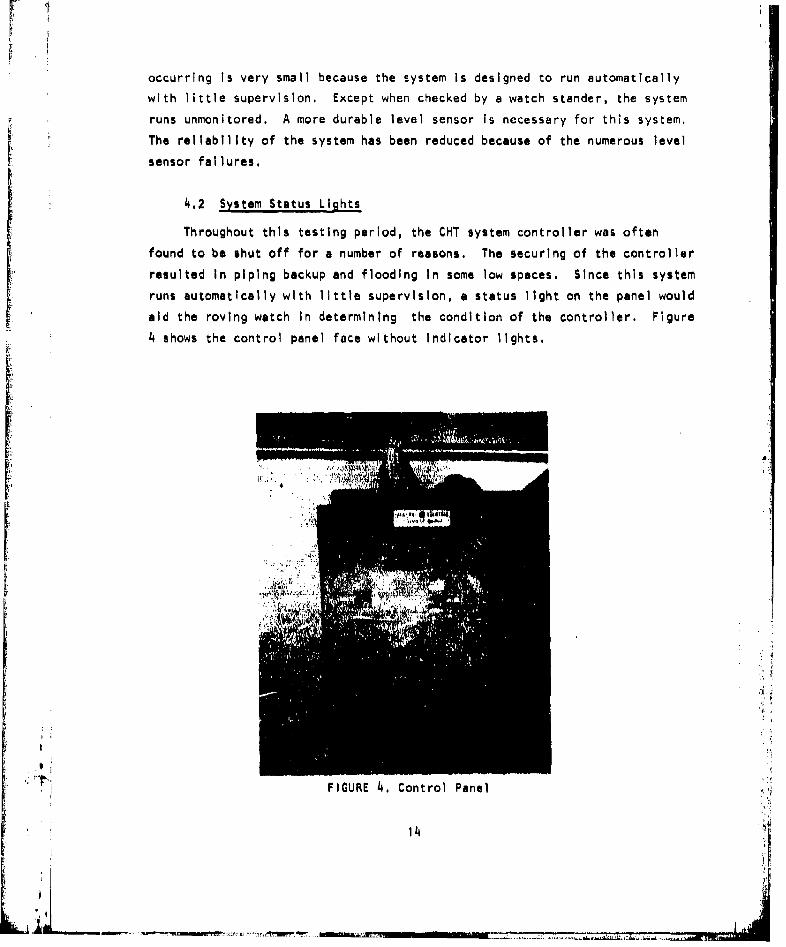
4.2 System Status Lights
Throughout this testing period, the CHT system controller was often
found to be shut off for a number of reasons. The securing of the controller
resulted in piping backup and flooding In some low spaces. Since this system
runs automatically with little supervision, a status light on the panel would
aid the roving watch In determining the condition of the controller. Figure
4 shows the control panel face without Indicator lights.
FIGURE 4. Control Panel
.1, 14
, ir;m

The controllers of this system are protected by low voltage protection
(LVP) devices that secure the power to the controller if there is a power
drop or loss. This device must be reset manually when full power is restored.
Unless the pumps are actually running, there Is no way for the roving watch
to determine If the controller is on other than physically pushing the
"Start" button and listening for a quiet click In the controller relays. The
addition of status lights will make for safer operation of CHT systems.
These lights should include the panel "OFF/ON" status and the pump mode se-
lector switch settings of the motor controllers.
f.3 Exterior Tank Level Indicator
When performing work on the CHT tank, It Is difficult to determine the
level inside the tank. The only rough indicators at present are the electric
level sensors. As discussed earlier, the failure rate of the level sensors
presents some concern for using this method of determining the tank level.
In addition, depending on the installation, there is no sure way of telling
what is the actual level wher, the level sensor closes, It is Imperative
that thi operator know the exact level of the tank before any accesses are
opened. For example, on the majority of the ships visited, the transfer
pump loses suction on the tank when the level of the tank is still above the
10% level sensor access, Unless the operator is aware of this, removal of
the 10% level sensor for repair will cause an unpleasant situation.
4, 4 DC Controllers
Two ships that were activated were equipped with DC controllers Instead
of AC controllers. Both the PAPAGO and RECOVERY have DC current as their
primary power sources, The PAPAGO uses 230 volts DC in the controller,
while the RECOVERY uses 115 volts DC. While observing the relay switching
action on both ships, considerable arcing was observed, It was more pro-
nounced on the PAPAGO than on the RECOVERY. In addition, Investigations
p grevealed that the contacts on the PAPAGO were showing excessive amounts of
pitting, while the RECOVERY's were not. The failure on the PAPAGO of the
S.4. two relays (#1 Motor Controller and #5CR control relay) can be attributed
to the higher voltage which burned the contacts off the motor control relays
15
•, .

and completely fused the control relay. It may be beneficial to operate the
DC controller circuits by using lower voltages in these systems.
Another DC control relay discrepancy noted was the tendency of the
screws attaching the movable contact plate to the relay throw arm to work
loose and fall out. This was observed on the RECOVERY on two occasions. As
a result, the duty pump continued to run past the lO mark. Lock washers
were Installed with the set screws, but they were not sufficient. A more
reliable method of securing these screws Is necessary.
16
"4
-

5. SOFTWARE
As with the hardware difficulties encountered, a number of software
problems were encountered during this project. This chapter identifies
and explains these problems.
5.1 Repair Parts Support
Failures of various components of the CHT system have been previously
discussed. Obtaining replacements for the failed components became an in-
volved process. The reason for the difficulty in obtaining the replacements
was Investigated and a fundamental repair parts support problem was discover-
ed. The majority of the ships did not have the necessary Allowance Parts
list (APL) pages for their Consolidated Shipboard Allowance Lists (COSAL).
The APL pages that the ships had were thm preliminary pages that were pro- .8
vided to them when the CHT systems were Installed. These APL's did not have
the necessary Information needed to order the repair parts. The COSAL's had
not been up-dated, and the required complete APL pages had not been requested
Without the correct APL pages, the operators were unable to obtain the nec-
essary repair parts through the Navy Supply System. Since there was no
demand detected by the Supply System, no repair parts were readily available.
Extensive delays were encountered when the parts were finally ordered.
The appropriate APL pages were requested by the individual ships, but
they have not been received as of yet, A delay in the distribution of the
APL's has been acknowledged by the Supply Center In Mechanicsburg and is
presently being corrected. '
5.2 The Sewage Disposal Operating Sequence System. (SDOSS)
Th SDOSS manuals have been provided to the majority of t,.e ships visited.
Those who do not have them at this time are being provided with them In the
near future. The manuals are of some use to the operators, but there are
17
difficulties with the layout of the manuals. Figure 5 Is provided as an
example, This page was taken from the SDOSS manual for the PORTLAND. This
page Illustrates a number of decks and spaces which the CHT piping system
runs through. To an Individual unfamiliar with this type of document, this
diagram is difficult to follow and to understand. The personnel responsiblefor the CHT system most likely have never been exposed to this type of docu-
mentation system. An Informal survey was conducted, and it revealed that
the SDOSS was not being used because of the confusion that It produced. The
format of the manuals should be modified to make It easier for the users to
understand the information provided.
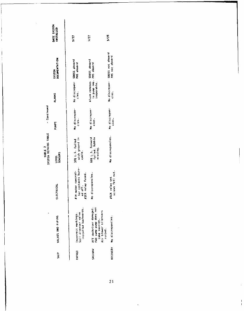
5.3 Maintenance
The maintenance held on the CHT system Is less than adequate for systems
that have never been used. Some maintenance Is being accomplished on the
major components such as pumps and diverter valves, The degree of mainte-
nance accomplished differs from ship to ship. There Is a Preventive Main-
tenance System (PMS) package developed for the CHT system. See Table 2 for
the ships that have the PMS installed.
Maintenance was not being performed on the level sensors, aeration sys-
tems, and the collection tanks, This was apparent by the number of level
sensors that were found to be faulty, the number of air silencers that were
rushed out, and the number of tanks that had septic sewage in them, even
though the systems were secured and layed-up. Table 2 is provided as a
summary on the corrective maintenance required of each ship visited. A more
detailed discussion on the Individual maintenance required for each ship can
be found In the ship reports In Appendix B.
It appears that there Is a correlation between the degree of difficulty
encountered when attempting to activate a system and the length of time be-
tween Installation and activation. Maintenance practices also play a large
part In determining system activation effort. (I.e.--the less maintenance
performed, the more difficult the activation).
18

z-
0 #,e
VV
............ 0
z 0
LU\
e Oz0 ~ ~ 0 e zd;.:..4 0
U-
4
070.
3tL.
.... .... .... ..
-~ -~ 0

4A uW
AL
*0 0
om
2 004 .00 .0 041 .0 m41 m40O 41L CO 41 0 0
.m0. .0 .0
tA mLALAL LA A
LAL)0 0A. LO A. LA. CLA mAO
11 41 I1 41 4
0. 0. 0. 0 0Si 4 0.1 SI S
u -, U (:h 3
-V0 0 "0 0 0
00N 0.
C4 C
410 00 c11 44
In LA C0 - 4 -L
,Q 0
NL m
-I0 0i *- .?~0 S
I- v 0- M1. - 0 ci 0 *4
u a1 0 LI -0 V m06J >4. C .0 00 a U
LAL 0h4 m0 V-
u~0 LAO-
5-~.1 *Sc 3.5
) c > - .- I I
-O m C c05
05-L C .- Li. 41 4
O -r E (100S 00 u I 41 w1 0-.
241 0.> .0 5 0. 0.~l0
w- - 0. 0i~ C 5 - -041' 0.C1 41 ~
I-~~~ ccl4U01 * . I
- CD -o Si >0 0.
41 .~ 41 41i4120
ChU
V V .
m 0
0L00 0 V 000 Ox 0 &
4A0 'A. 4L. 'AL
I 'AIEU I.)I E
CLC
-J 0 -
aCC 'A V
LIU U.
cc000
4) t m 4)
dU 0 E
a U CL u
4m 0 404' 1U.- ,u
~I 10 EU EU
I- ~ Z ~ 3U ~ 'at0 WW 0 0
) .. JO -21

5.4 Training
While activating the CHT systems on the test ships, It became very ap-parent that the majority of the operators did not know how to operate the
system correctly. There Is a great deal of concern about the "Lnknowns" of
the system. Ship's captains have been directed to activate and use thesystem, but without direct Instructional aid, they are reluctant to do so.
The ships visited have sent personnel to the Navy training schools for
CHT operation Instruction, but the trainees reported that the material they
received was directed more towards maintenance than to the operation of the
system. The majority of the operators were required to "self learn" the
system and because of Inexperience with the system, spills and failures haveoccurred. As not to cause any more problems, the systems were layed up until
the time the ships could receive the necessary aid to learn how to operatethem.
At the beginning of each ship visit, concern and skepticism had to be
overcome. Once that had been accomplished, the commands and operators took
more Interest In the system. For CHT's to be universally accepted and oper-
ated on a continuous basis, more attention needs to be given to the concerns
of the operators. This activation project demonstrates that for a system of
this type, when there Is support provided by external sources, more Interest
Is taken by the operators.
NSTM Chapter 593 is available to ti-e operator, but the majority of those
asked did not know that It existed. Again, this relates to the general ig-
norance about CHT system. Another difficulty is that the technical manuals
for the systems have not been received by some of the ships.
i A
22

rL
6. CONCLUSIONS
The primary reason the sewage generation analysis was initiated was to
obtain an insight to the actual generation rates of U.S. Navy ships. Second-
ary to the main task was the activation of the nine ships In the Norfolk
area. Throughout the project a number of conclusions about the operational
status of the CHT system were developed. The following conclusions were
developed while working with the ships and are presented to give some Insight
on how the system is operating and progressing to meet the 1981 activation
goal.
6.1 Wastewater Production
As discussed In an earlier chapter, the data that was collected andS summarized In Table I shows that there Is definitely a higher sewage genera-
tion rate than was anticipated. The per capita daily averages presented In
Table I show considerable differences between ships. This trend Is to be
expected for all CHT systems. Of the eight ships reported on, only two were
determined to be within the 60 gpcd standard for sewage generation during
the normal everyday configuration before minor controls were accomplished.The remaining ships were anywhere from 1.5 to 7.2 times the design standard.
The fleet daily average generation rate can be expected to be between i44 and
157 gpcd. This is 2.4 to 2.6 times the original 60 gpcd design estimates.
From the data shown, the 60 gpcd standard appears unrealistic and can-not be met with ships using their present day practices. Guidelines are
necessary to help control the amount of constant flushing required to combat
scale formation in the soil lines, and to encourage the practice of securing
galley drain eductors after use. These sources contribute most of the ex-
cessive wastewater volumes.
Extensive "hands off" monitoring of wastewater volumes from at least 30
ships with CHT systems is necessary to confirm the data from the relatively
small sample presented.
23
iJi
Wastewater volumes can be monitored by either:
-Extensive data collection from at least 30 ships during a 60-90
day period.
-Each ship maintaining a log of pumped volumes calculated from pump
cycle counters Installed In each cont;'el panel. (Previously re-
commended to provide operator control ;nformation).
-Measurements from shore side Installed vclume meters on each pier
riser.
-Rough estimates from PWC supplied wet well volume measurements.
On the NEWPORT class LST's, the laundry Is a large producer of gray
water. Operators exhibit no apparent concern for the conservation of fresh
water use while In port. Therefore, the laundry Is used in such a manner
that small Individual loads are done instead of larger, more efficient water
usage loads. The FAIRFAX COUNTY produces 8 times more wastewater forward
with the laundry collected by the CHT tank than with the laundry diverted
over the side. The SAGINAW produced 2.4 times more than with the laundry
diverted,
The calculation of the transit times for the ships monitored Indicated
that none of the ships could totally meet the 12 hour holding time require-
ment while transiting. The constant flushing of urinals appears to be the
major cause of this problem. Other typical causes were the collection of the
air conditioner drains by the CHT system (VULCAN), and Insufficient tank size
to handle the load (PORTLAND and BEARY).
6.2 Hardware
Throughout the performance of this project, the completion of the ob-
jectives was hindered by the previously outlined hardware discrepancies.
These discrepancies are a detriment to the successful crew acceptance and
operation of the CHT system.
The level sensor's rubber covering appears Inadequate as the corrosive
content of the tank and abrasive action against the tank wall causes severe
deterioration. This leaves the wiring susceptible to grounding.
A tank level Indicator, regardless of the design, Is needed because
24
* IA

of the Inability of the operator to determine the level of the fluid within
the tank.
Indicator lights are needed to show the status of the system, particu-
larly If it is "ON'' or "OFF".
Various check valves leak-by allowing raw sewage into the aeration
systems, and In the case of the PAPAGO, allowing sea water to seep back into
the holding tank from the discharge lines.
The above noted hardware discrepancies make it difficult to operate and
maintain this system with confidence.
6.3 Software
The software for the CHT system Is failing to provide the support In-
tended. At the present time, there appears to be a large degree of igno-
rance about the system, and the Introduction of the CHT system Is being met
with skepticism and concern. More emphasis Is required in training personnel
In the operation of the system. The training provided now at the formal
schools Is insufficient to meet the needs of the operators and to ensure that
the system Is operated with confidence. At present, the curriculum deals
mainly with maintenance rather than with operational techniques.
The user guides (SDOSS) are not providing satisfactory guidelines andSinformation for the operation of the CHT system. The SDOSS manuals are slow
in being developed and implemented and there appears to be little Instruction
given on how to use the manuals. In addition, the diagrams are difficult to
follow.
The technical manuals are not always provided to the ships when their
systems are installed. Without these manuals, troubleshooting and main-
tenance cannot be performed.
The repair parts support does not provide the necessary parts when they
are required and the necessary APL pages are not held by the CHT ships.
These pages are available at NSC Mechanicsburg, but the distribution has beenSslow.
The PMS is adequate for the pumps and valves, but changes are required.• In the frequency of tank flushings and level sensor checks.
To make the operation of the CHT system more acceptable, the problems
25
•. I.I.....I

of the software support have to be addressed. Without the proper support,
the shipboard skepticism and concern over CHT operation will remain.
26
V,

7. RECOMMENDATIONS
Throughout the CHT field evaluation% conducted in the Norfolk area, PA
Engineering personnel worked closely with the users of the CHT system aboard
each ship visited. In addition, close liason was held with the maintenance
personnel at COMNAVSURFLANT. A considerable dmount of Information was gained
during these studies. The individual field reports are very detailed on the
findings of each ship and give an Insight as to the average condition of typ-
ical CHT systems. Individual recommendations were made for each ship to up-
grade Its system and also to upgrade the overall CHT program, The following
sections contain recommendations that may enhance the operation of the CHT
system and aid In the acceptance of the entire program.
7.1 Wastewater Reduction
The data collected shows the sewage generation rate Is excessive for
most ships, The major reoccurring causes were determined to be the high url-
nal flushing volumes necessary to control the scale formation In the soil
drains and the constant running of the galley eductors and the tank flushing
systems.
The followrng recommendatoons may reduce thale 1 of C ther Con-
trolled Averag re of mn8 to 99 ipcd, shown In Table I of Chapter 2d
1. Install solenoid valves on all garbage grinders and other salt water
eductors to automatically secure them when not In use,
2. Insure that all tank flushing valves are labeled "'s" and regular-
ly checked.
The daily ship per capita load may be reduced to near or below the
design average of 60 gpcd If the following additional recommendations are.Naccomplished.
27
II

3. Successfully solve the scale buildup problem in urinal drain lines
and provide guidelines for constant urinal flushing.
Ii, Accomplish SHIPALT's to remove any salt water cooling drains or
other non-sanitary high volume drains from the CHT system.
5. Reduce wasteful laundry operation practices.
6. Divert gray water overboard where possible for extreme situations.
Before concerning shipboard personnel with limiting the quantity of
wastewater produced, the overall cost and savings must be determined, More
important, If the ships become required to monitor sewage volumes and control
saltwater use too soon, there will be extensive fleet resistance to such a
program which can hinder meeting the 1981 full operational goal. When the
use of CHT systems becomes routine the operators will more easily accept and
understand the need for a program to control excessive wastewater production.
Until then, the actual Cost of fleet sewage processing should be closely mon-
itored and the extent of excessive wastewater production watched as more ship
CHT systems get activated. ,-
7.2 Hardware and Operations
The detailed ship reports contain several recommendations to help In
CHT system operation and should be considered by NAVSEC for future system
designs or alterations. Some 15 ships with CHT systems have been activatedby PA Engineering during the past year and a half In Norfolk and San Diego,
and this work has confirmed the need for these recommendations.
1. The pump control panel needs an Indicator light to show If the
control relays have been reset, This light will give the operatoror the roving watch a simple Indication that the start button has
been reset. Typically, after a power failure the controller Is not
reset and the watch Is not aware that the control relays are de-
activated. A lamp set into the panel door and wired between terml-
nals 9 and 8 would Indicate when the control relays have power.
Figure 6 shows a wiring schematic of this Installation.
218

4
INDICATOR LIGHT
9ROTARY SWITCH 101 EE
2M RESET
I 14 15
IICR
FIGURE 6.Wiring Schematic for Indicator Light
29

2. Other Indicator lamps for the controller are needed to indicate If
the pumps have been switched to the automatic position and to In-
dicate the status of the duty and standby pumps.
3. The controller should be modified to prevent the activation of the
standby pump when the 30% level sensor is reactivated by wave
action In the tank. In large tanks the majority of pumping cycles
is by the two pumps due to the sloshing of waves in the tank.
4. High volumes of wastewater are being generated on some CHT ships.
Often this Is the result of saltwater valves being left on or
problems in the plumbing system. There is no way for the ship to
know If the volume of wastewater pumped is excessive. A 120 volt
event counter should be set Into the control panel door and wired
between terminals 10 and 14, This will Indicate how many times the
duty pump level (30% level) has been reached. By knowing the
volume between the 30% and 10% levels the CHT operator will know
the volume he has pumped. Figure 7 shows the wiring schematic for
the counter Installation.
5. For safe operation and maintenance of the CHT tank and pump, It is
necessary to know the level inside the tank. In our testing pro-
gram we have used a portable tube with a fitting screwed Into the
drain plug of the pump. This gives a good indication of tank level
as the liquid rises up the tube to the height of the water Inside
the tank. This portable tube is useful but Impractical for ship-
board installation. A removable clear plastic tube could be fitted
alongside the tank attached to a petcock drilled into the tank near
the suction level of the pumps, The top of the tube would be
fixed to another patcock near the top of the tank and a screen at
the Inlet of the petcock would help keep solids out of the tube.If the tube became discolored or dirty, it would be easily removedand cleaned. This cleaning operation could be quickly and safely
done and would be simpler than most CHT maintenance tasks.
6. We have seen several broken pipe handles and cast Iron fittings
"for the valve handles of the Isolation ball valves. Another type
of handle for these valves should be found.
30
S...-- ..

2 UFU
I - . . . I I OLIO
ROTARY SWITCH I RESET
I I i I I14.iII I
I I II I J • 1120v EVENT COUNTER
r • " ""-' " 20L
ROTARY SWITCH RESET
I I I
IiCR
FIGURE 7. Wiring Schematic for Event Counter
31
; A

7. The "T'' handles for the jack screws on the pump check valves should
be replaced with a larger round handle. The larger round handle
would make It easier to open the check valve for discharge line
draining and would eliminate a blunt point that Is dangerous when
crawling around the piping in cramped pumprooms.
8. Most of the pump control panels contain two voltage cources. A440 volt power source is provided for the pump motors and controlrelays through a transformer. A separate 120 volt source Is pro-
vided for the alarm circuit. This second voltage source is not
always obvious to the electrician. A warning sign on the panel
door is needed to warn of the two voltage sources.
9. The PMS card that requires the test operation of pumps and high
level alarms should be Increased from quarterly to at least monthly.
The weekly tank flushing for operating CHT tanks should be Included
as part of the PMS system.
10. We suspect the majority of failures with the mercury level sensors
are the results of the failure of the cover Insulation of the 4
wire bundle. The cause of the sensor failure should be examined A
more closely to determine If a more suitable material is available.
Because of the unavallibility of replacements, temporary fixes
have been made using the spare leads, red and green, of the wire
bundle.
II. The silencers for the air blowers are rusting out from water and
sewage collecting in them when the CHT system Is not In use. Also,water tends to leak-by the air check valve when the tank overflows.A drain Is needed in the low point of the silencer to remove the
collected water. Such drains were Installed In the air system of
the USS Saginaw. Additionally, an Isolation valve should be In-
stalled to prevent sewage passing Into the air line when the air
Is kecured. Figure B shows a silencer with a drain line on the
SAGINAW.
32
----- J-

- ~- - m s,-.- .
I"
FIGURE 8. Silencer with Drain
12. Some protection should be considered to prevent the pumps from run-ning dry if the low level sensor fails. A running time limiter inthe control circuit Is one solution. A series backup sensor usingthe red/green spare switch of the mercury sensors could also pro-vide some additional protection. This problem Is of concern be-cause of the dependent design on the low level sensor In the con-trol circuitry and high number of sensor failures we have observed.
33
•.,4
'I,
PART I I
P IER OPERAT IONS ASSESSMENT
SiA

PIER OPERATIONS ASSESSMENT
1. INTRODUCTION
For the period May through October, 1978, PA Engineering conducted a
pier operations assessment of the ship sewage collection systems located in
the Norfolk area. The objectives of this project were to provide technical
documentation consisting of operations and maintenance support data and
recommendations to insure compliance with the Navy's OPNAV Instruction to
achieve CHT operational status by 1981. Selected portions of the Naval
Amphibious Base, Naval Shipyard, and Naval Station were evaluated for capa-
city as determined by the as-built drawings provided. Also, necessary pro-
cedures were determined to effectively operate the systems under normal
conditions and to respond to emergency situations as well.
The following sections of each Naval facility were evaluated:
Naval Amphibious Base - Piers 56 through 59 and Quaywall berths.
Naval Station - Piers 20 through 23.
Naval Shipyard - Drydock 3, 4, and 8.
35
"It3

2. SYSTEM DESCRIPTION
The collection systems described In this report were installed in 1973-1974 to enable each activity to comply with the Federal Water Quality Act of
1972 as specified In DOD Directive 6050.4. They are designed to collect
shipboard generated wastewater and convey this material to the local munici-
pal treatment plant. The local facility is operated by the Hampton Roads
Sanitation District with headquarters in Virginia Beach, Virginia.
Design of the systemsfollowed those requirements set forth in NAVFAC
Design Manual DM-5, April, 1974. The basic layout as determined in this
study generally follows the requirements as established,with major exceptions
In the areas of capacity,to receive peak flow (as determined by DM-5 methods)
from maximum planned berthing arrangements and minimum full pipe flow veloci-
ties to prevent deposition of solids. These areas are described In the
Conclusions and Recommendations sections of this report.
The three systems Investigated Incorporate suitable piping materials
and connections to facilitate ship to shore sewage transfer. Major sections
of pipe run are exposed ductile Iron suspended below pier structures. Be-
cause of their location,exposed to the weather and with minimum slopes, there
Is reason to believe that cold weather may affect systems operations by way
of the deposition of solids and freezing of pipe contents. This necessi-
tates additional maintenance procedures to insure continuous operation.
2.1 Gravity Sewer System
The gravity sewer systems located at these three facilities provide for
ship to shore connection via deck risers and subsequent sewage transfer
through sloped portions of sewage conduit. Main lines extend to the pump
stations which receive and transfer the sewage Into force mains for transport
to the municipal treatment plant.
37

. ... ... ,......... ..- . .
I~I
At the Little Creek facility, pier piping extends along one side of each
pier and collects material from opposite side collectors by way of lateral
sections of pipe. Absent at this facility are clearout access points along
the pier lines. This necessitates the use of the pier risers In certain
situations as access points to flush the pier side systems.
At the Naval Station, two separate pier lines run the length of each
pier that was studied. Each side of the pier Is equipped with a full sewer
line running the entire length of the pier. Also, cleanouts are provided
for water flushing of the lines as that becomes Incorporated as a standard
procedure for maintenance purposes. These destroyer and submarine piers
consist of multiple connections with a "Y"I fitting joined to the main pier
line and accessed by two four inch camlock fittings. This requires consider-
ation when a ship is pumping Into one side of the collector. Should access
to the second camlock riser be required it will be necessary to request
ship's personnel to temporarily close the ship deck riser while access Is
made tothe other camlock fitting.
The Norfolk Naval Shipyard system that was Investigated consisted of the
dry dock facilities, numbers 3, 4, and 8. Drydock 3 Is a typical gravity
type system as well as dry dock number 4 where sewer main Is extended along
the Interior walls of each dry dock and outfitted with ship to shore connec-
tions, clean outs, and vents,
Review of the as-built drawings of the gravity systems at all facilities
reveals that full flow velocities are generally less than those stipulated
In the DM-5 manual. In the case of the Naval Station, velocities along the
pier generally range In the neighborhood of 1.7 to 1.8 fps. The DM-5
minimal requirement is established at 2.5 feet per second. This situation is
not unique to the Naval Station and also occurs in the gravity systems which
were studied at Little Creek and Portsmouth. The net result is the need for
increased inspection for the settling of solids with the potential for block-
age as the system Is used. Routine Inspections should be conducted by lift-
Ing the manhole covers at each of the facilities and observing for these
characteristics,
The sewage from shipboard Is transferedto existIng pump stations which
' ,have wet wells and, typically, main duty pump and stand-by pumps, to be
' I3

operated when flows exceed the capability of the main pump. These stations
are routinely Inspected on a daily basis at the Naval Station and this pro-
cedure should be carried over to Portsmouth and Little Creek.
2.2 Pressure System
Drydock 8 at the Portsmouth shipyard is fitted with a force main pros-
surized by salt water directed through a flow rate controller. All ship to
shore connections are Isolated by gate and check valves. Since slope Is of
no consideration In this type of system there should be no problems of solids
buildup end minimal freeze problems If the saltwater line Is activated
regularly. Care should be exercised, however, to control the volumes of
salt water Introduced ultimately to the municipal treatment plant.
I-
3,
I t~
3,
Li_•

3. DESIGN EVALUATION
The method used to analyze the shore side collection systems consisted
of obtaining the available as-built drawings of each of the systems. Sup-
plemental to reviewing these drawings, visits to each of the facilities were
conducted and Included a walk-through of each system.
The drawings were used to determine the lengths of pipe installed, the
slope at which they were Installed, and the diameters of each section. These
values were then applied to the Manning formula nomograph to determine full
flow velocities and discharge rates,
3.1 Full Flow Velocity And Capacity
At the Little Creek facility, velocities at full flow appeared to be less
than the DM-5 minimum requirement of 2.5 fps. A review of the accepteddesign calculations showed that these designed velocities pertained to pipes
of larger diameter. This results In the system full flow velocities being
lower than required to prevent the settling of solids in the line when the
system is in use.
The capacity of each pipe run Is sufficient to handle the volume
of sewage expected from the estimated berthing arrangement of each facility.
However, when applying DM-5 peak flow calculations to these berthing arrange-
ments it appears that the flow rate capability of these sewer systems does
not meet the peak flow requirement as calculated. This calculation Is based
on the maximum single pump rate capability of the largest ship at berth added
to the average flow rate expected from the remaining ships at berth. This
formula Is deficient since experience with CHT systems shows that pumping is
intermittent and does not produce outflow on a continuous basis. It is un-
likely that all pump systems on all ships at berth will be activated simul-
should not be exceeded.
41I'
3.2 Berthing Limitations
Berthing arrangements at these facilities are decided on the basis of
power availablilty and personal preference. Since the volumetric capacity
of the sewer lines at each facility Is sufficient to handle large volumes of
sewage and sewage pumping Is on an intermittent basis only, these shore side
collection systems should be able to handle berthing arrangements based on
F the above criteria. All pump stations are equipped with duty and standby
pumps which will allow for maximum anticipated flows.
The wastewater production data presented in DM-5 estimates a per capita
discharge rate at 60 gpd. Based on the ship side study presented previously
In this report, this number Is lower than actual wastewater production. As
shown In Table 1 of Part 1 normal daily generation rates average 144 gpd
per man, This Is more than two times the estimatod value given In DM-5. A
prime factor for these high rates In the ship activation study proved to be
the operation of high volume sources such as constant flush urinals and gar-
bage grinder eductors In continuous operation. To effectively match up
shore side capabilities to ship side production, it will be necessary to
determine more reliable estimates of this generation rate. Also, In the
case of amphibious craft It must be considered whether ship's complement at
pler side will include troops aboard.
I 4Lb
Li[-

4. OPERATIONS AND MAINTENANCE
To Insure that the shore side collections system Is a'dependable utll-
ity, it Is necessary to provide regular maintenance and service procedures.
These activities must Include a systematic program of cleaning, Inspection,
and repair that reduces breakdown to a minimum, The recommended policy to
establish this preventive maintenance plan Is as follows:
1. Execute a basic plan of routine maintenance,
2. Immediately investigate all complaints and correct faulty
conditions.
3. Continue routine Inspection for any physical damage and perform
necessary repairs.
Personnel requirements to accomplish an efficient sewer maintenance
program are available from the local public works department of each activi-
ty. These Include supervisory personnel as well as maintenance and emergen-
cy crews . The maintenance crews should also Include individuals capable of
Inspecting the system for damage and potential problems, Also, they shouldbe fully equipped to perform routine cleaning assignments, More frequentattention should be given to those sewers known to be sources of trouble.
Emergency crews should be headed by a foreman capable of responding to
emergency situations and should be equipped with the necessary equipment
such as safety harnesses, blowers for artificial ventilation, and repairmaterials such as pipe patches and pipe plugs, Also, safety considerations
require the use of rubber boots, gloves, and safety helmets (see Figure 9),
43
IL.J LA ____ ______ ______

I 7,
',+ , I.
I,
FIGURE 9, Maintenance Equipment a
4.1 Normal Maintenance
Preventive sewer maintenance should Include a systematic cleaning of the
entire system. This Includes the removal of blockages, and the planned In-
spection of known trouble areas, The frequency of such cleaning procedures
should be determined as operational experience Is gained. More frequent
cleaning should be Instituted where necessary. This Is Important to reduce
the blockages brought about by the lower velocities of this system, Special
considerations for these facilities which promote more frequent cleaning
schedules are:
1. The sewer Is laid at a relatively flat grade.i•2, The Intermittent flow of ships' waste. :
3, The use of shipboard garbage grinders.
44
Inspection of the sewer system Is easily performed by lifting a manhole
cover, looking into the manhole and establishing that there is adequate flow.
This activity does not constitute an entire Inspection program, however it
can provide early warning of problems and should supplement an overall pre-
ventive maintenance program.
Blockages most usually occur in the manholes. These can be caused by
grease, sand, buckets, sticks, rags, or breaks in the sewer line, Hydraulic
stoppages are often found In long sewer line runs Installed with flat grades.
Barriers to the Incoming sewer stream can cause the buildup of greabe, the
deposition of solids, and the eventual physical pluging of the line. When
a blockage Is reported, manholes should be Inspected until the first dry
downstream manhole is reached. It can be assumed, then, that the blockage
is between the first dry downstream manhole and the next manhole upstream.
it Is possible, then, to Insert a rod upstream from the dry manhole afford-
Ing the advantage of a clear manhole from which to work. Complete blockages
caused by sand, grease, or debris may be opened and removed by flexible
steel rods. Subsequently, hydraulically operated cleaning devices can be
used. Some activities, such as the Naval Shipyard, use contracted sewer
repair and maintenance services.
4.2 Emergency Procedures
Aside from normal Inspection and maintenance procedures, certain con-
ditions may arise whereby there Is a large instruslon of sea water Into the
system by a pipe break on a pier line which is submerged. The emergency
procedures to be foilowed are documented In the Individual SOP's following
in the Appendix of this report. Basically, they consist of installing pipe
plugs of different types and sizes or pipe patches for quick and temporary
repairs, Those sections of pipe which are temporarily taken off the line
due to such failures may be bypassed by extending longer sections of 4 Inch .3
hose from the ship to the next downstream pier riser that Is In operation,
An alternative to this Is to simply lead the 4 Inch hose Into a working
downstream manhole. The pipe plugs shown in the Appendix consist of inflat-
able ball plugs, Inflatable bag plugs, and the screw type disk plug. All
plugs are Inserted Into the sewer line through the manhole and tightened to
45

Fiseal the outer edges of the plug to the inner wall of the sewer pipe. Care
should be taken during this operation for the safety of the personnel enter-
Ing the manhole. These safety procefrtes are detailed in the individual
SOP's In the Maintenance and Safety chapters.
I..II4

5. CONCLUSIONS
The following are conclusions concerning the operation of pier sewers.
These conclusions are the result of work with ship sewage systems using the
pier sewers and working with shore side operating personnel, Although they
are the result of examining Norfolk area systems, they apply to most other
Navy pier sewer installations.
1. The majority of pier piping sections and underground sewer mains
have been installed with a relatively flat grade, In most cases,as was mentioned previously, maximum capacity full flow flow rates
are less than 2 fmet per second,
2. Pier piping evident at all facilities Is suspended below pier level
and is exposed. This exposed pipe may tend to freeze in coldweather conditions and require additional maintenance.
3. NAVFAC Design Manual (DM-5) presents estimates of wastewater gen-
eration which are lower than actual measurements recorded.
4. The peak flow equation given In DM-5 is not realistic to the extent
that it does not consider the Intermittent pump cycling of CHTsystems on board ship, Attempting to match up the capacity of the
shore side lines to the peak flow derived from this equation gives
the result that the shore side lines are not capable, or at least
minimally capable, of handling peak flow. However, experience
shows that CHT pumping cycles occur Intermittently and for short
duration only. It Is unrealistic to assume that all ships berthed
at a given set of piers will be cycling at exactly the same time,
hence, the loads to the shore system will not approach the calcu-
lated peak flows.
47
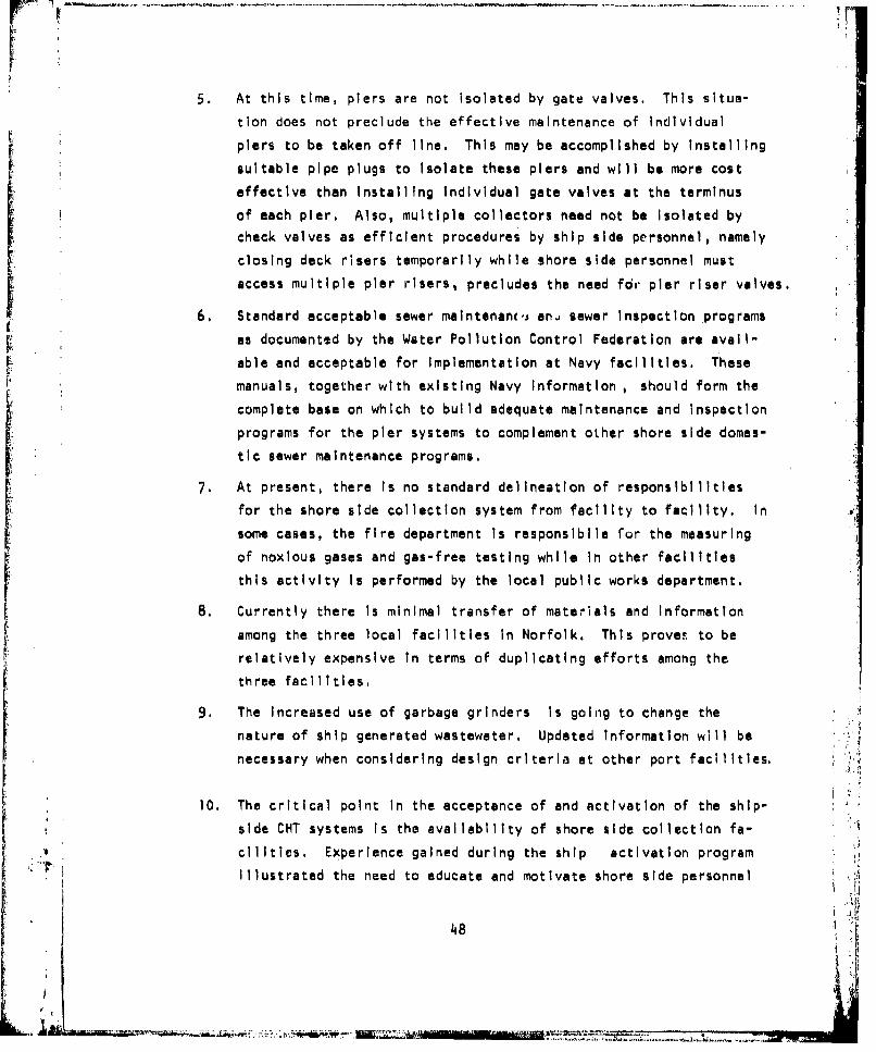
5. At this time, piers are not isolated by gate valves. This situa-
tion does not preclude the effective maintenance of Individual
piers to be taken off line. This may be accomplished by installing
suitable pipe plugs to Isolate these piers and will be more cost
effective than Installing Individual gate valves at the terminus
of each pier. Also, multiple collectors need not be Isolated by
check valves as efficient procedures by ship side personnel, namely
closing deck risers temporarily while shore side personnel must
access multiple pier risers, precludes the need for pier riser valves.
6. Standard acceptable sewer maintenanc.. an, sewer Inspection programs
as documented by the Water Pollution Control Federation are avall-
able and acceptable for Implementation at Navy facilities. These
manuals, together with existing Navy Information , should form the
complete base on which to build adequate maintenance and Inspectionprograms for the pier systems to complement oLher shore side domes-tic sewer maintenance programs.
7. At present, there Is no standard delineation of responsibilities
for the shore side collection system from facility to facility. In
some cases, the fire department Is responsibile for the measuring
of noxious gases and gas-free testing while in other facilities
this activity is performed by the local public works department,
8. Currently there Is minimal transfer of materials and Information
among the three local facilities in Norfolk. This provet to berelatively expensive in terms of duplicating efforts among the
three facilities.
9. The increased use of garbage grinders Is goin~g to change thenature of ship generated wastewater. Updated Information will be
necessary when considering design criteria at other port facilities.
10. The critical point In the acceptance of and activation of the ship-
side CHT systems Is the availability of shore side collection fa-
cilities. Experience gained during the ship activation program
Illustrated the need to educate and motivate shore side personnel
48 r

to ready collection systems as soon as possible. In some instancesships were prepared to offload only to find the shoreside system
Inactive.
i A
!, t
49
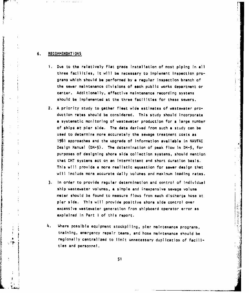
6. RECOMMENDATIONS
1, Due to the relatively flat grade Installation of most piping In all
three facilities, It will be necessary to Implement Inspection pro-
grams which should be performed by a regular inspection branch of
the sewer maintenance divisions of each public works department or
center. Additionally, effective maintenance recording systems
should be Implemented at the three facilities for these sewers.
2. A priority study to gather fleet wide estimates of wastewater pro-
duction rates should be considered. This study should incorporate
a systematic monitoring of wastewater production for a large number
of ships at pier side. The data derived from such a study can be
used to determine more accurately the sewage treatment costs as
1981 approaches and the upgrade of Information available in NAVFAC
Design Manual (DM-5). The determination of peak flow In DM-5, for
purposes of designing shore side collection systems, should mention
that CHT systems act on an Intermittent and short duration basis.
This will provide a more realistic equastion for sewer design that
will Include more accurate daily volumes end maximum loading rates.
3. In order to provide regular determination and control of Individual
ship wastewater volumes, a simple and Inexpensive sewage volume
meter should be found to measure flows from each discharge hose at
pier side. This will provide positive shore side control over
excessive wastewater generation from shipboard operator error as
explained In Part I of this report.
14. Where possible equipment stockpiling, pier maintenance programs,
training, emergency repair teams, and hose maintenance should be
regionally centralized to limit unnecessary duplication of facill-
ties and personnel.
51
I'•
L! L• ____ ___

5. All shore side collection manholes and pier risers should be num-
bered to facilitate quick Identification for maintenance and repair.
Operation and warning plaques should be mounted at each pier riser
cis a ;de for inexperienced workers and shipboard personnel In an
6. All activities should be directed to consider shore side collection
as a priority goal to be met Immediately. There is some concern
as to the status of the systems relative to the 1981 goal of com-
plete operation. This goal may be met only by establishing the
importance of activating the systems to receive ships' waste as
soon as possible as not to hinder shipboard system startup during
the critical next two years.
7. It Is also recommended that each activity establish good working
relationships with local municipal treatment plant officers. Thiswill serve to avoid misunderstandings as problems occur from treat-Ing shipboard wastewater.
52
! I I

1 .1•• • ;• ;;.i, ' ' :'/ ......• •• ;- .•r•... .• ,F ; -" ,•,-r r ''•- • . . ..... ... .... .... ..... • • ..... .!i
APPENDIX A
t• ~STANDARD OPERATING PROCEDURES "
FOR
NAVAL AMPHIBIOUS BASE, LITTLE CREEK, NORFOLK, VA.
NORFOLK NAVAL STATION, NORFOLK, VA.
NORFOLK NAVAL SHIPYARD, PORTSMOUTH, VA.
LA
ii
.i- I ~ -

SHIP WASTEWATER COLLECTION SYSTEM
I STANDARD OPERATING PROCEDURES
FOR
I.PIERS 56, 57, 58, 59, and QUAYWALL
U. S. NAVAL AMPHIBIOUS BASE, LITTLE CREEK
NORFOLK, VIRGINIA
A
A•
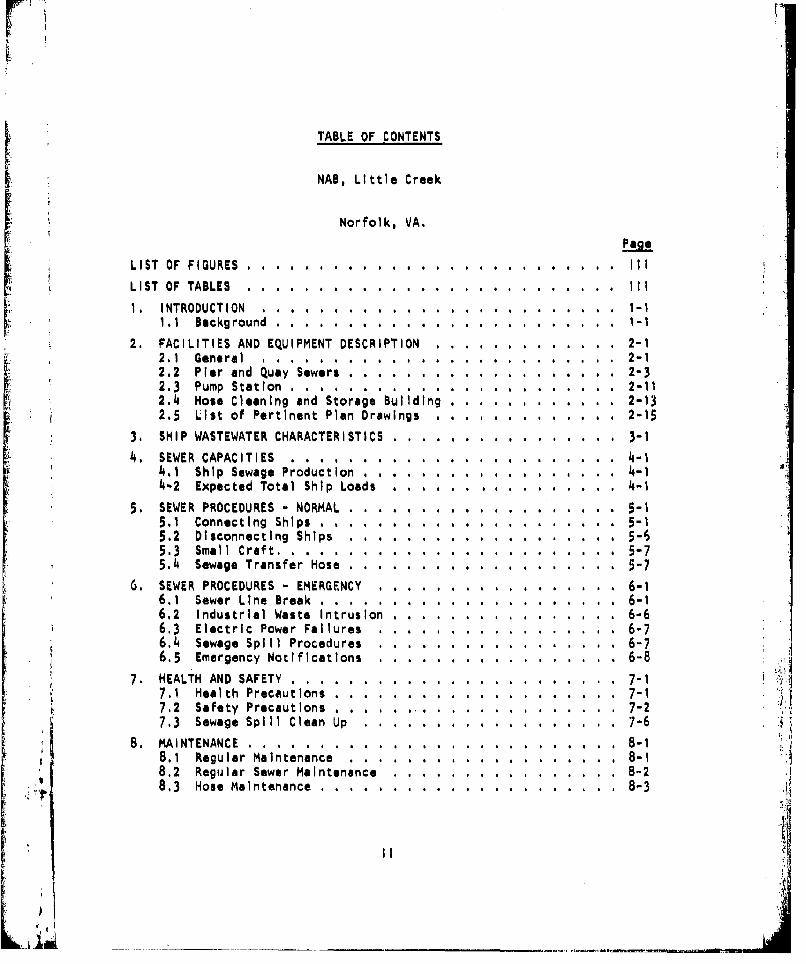
ri
TABLE OF CONTENTS
k• NAB, Little Creek
Norfolk, VA.
LIST OF FIGURES . . . . . . . . . . . . . . . . . . . . ... . . III
LIST OF TABLES......... . . ........ . ...... I..
1. INTRODUCTION . . . . . . . . . . . . ......... . .. -.i 1.1 Background ................ ..................... 1 -1
2. FACILITIES AND EQUIPMENT DESCRIPTION . . . .... ... 2-12.1 General .......... . . ....... . ..... 2-12.2 Pier and Quay Sewers . ............... . 2-32.3 Pump Station . . . . . ............... . 2-112.4 Hose Cleaning and Storage Building....... ... . . . . 2-132.5 List of Pertinent Plan Drawings . . . . . ...... 2-15
3, SHIP WASTEWATER CHARACTERISTICS . . . . . .. . .. 3-1
4. SEWER CAPACITIES . . . ................. 4-14.1 Ship Sewage Production . ....... 4-14-2 Expected Total Ship Loads . . . . . ........ 4-1
5. SEWER PROCEDURES - NORMAL . . . . . ........ . . 5-15.1 Connecting Ships .......... ......... 5-15,2 Disconnecting Ships ............ ............. . 5-65.3 Small Craft ............ ........... . ........ 5-75.4 Sewage Transfer Hose ......... ....... ........ 5-7
6. SEWER PROCEDURES - EMERGENCY ........... ............ . 6-16.1 Sewer Line Break .. . . .......... ... ......... . 6-16.2 Industrial Waste Intrusion......... ....... ....... 6-66.3 Electric Power Failures ............. ........ 6-76,4 Sewage Spill Procedures ............ ....... ..... 6-76.5 Emergency Notifications ................. .... .... 6-8
7. HEALTH AND SAFETY .............. ................. ... 7-17,1 Health Precautions .............. .............. .. 7-1 3.7.2 Safety Precautions .................. .......... .. 7-27.3 Sewage Spill Clean Up ............ .............. .. 7-6
8. MAINTENANCE... ................. . . . 8-18.1 Regular Maintenance. 8................. -18.2 Regular Sewer Maintenance .......... ........... ... 8-28,3 Hose Maintenance ........ ............... 8-3
ii
K.-_ _ _

WWI H
LIST OF FIGURES
PAGE
FIGURE
2-1 Sewer System Schematic ...................... .... 2-2
2-2 Receiving Sewer Layout ........................ .... 2-5
2-3 Quaywall - Dogleg Sewer Layout . . .......... 2-6
2-4 Pier Sewer Layout ........ ........................ 2-72-5 Hose Connection Cross Section..... ... . . . . . . . 2-8
2-6 Pump Station . . . . . . . ............... 2-12
2-7 Hose Maintenance Building.................. . . . . . 2-14
5-1 Log Sheet . . . . . . . . . . .......... . 5-25-2 Riser Adapter ... ......... . ............. 5-4
5-3 Safety Barricade .. . ..... 5-5
6-1 Air Inflatable Bladder Plug . ........................ 6-3
6-2 Mechanical Screw Vxpandable Plug .................... 6-3
6-3 Air Inflatable Rubber Plug . . ........................ 6-5
6-4 Sewer and Tide Levels ..................... ....... 6-4
6-5 Mechanical Pipe Patch .................... . . . . 6-5
7-1 Manhole Entry Equipment ........ ................... 7-4
7-2 Gasoline Powered Portable Blower ..... ............. ... 7-4
7-3 Gas Sampling Meters ........................... .. 7-5
7-4 Entry Procedures ........ ..................... 7-5
TABLE PAGE2-1 Little Creek
Details of Wastewater Collection System .2. ............ 2-9
2-2 Pertinent Plan Drawings ............................ 2-153-1 Ship Wastewater Characteristics .. .. . . . .. . .. 3-24-1 Ship Sewage Generation
Estimates and Field Data ...... ................. .. 4-3
4-2 Summary of Planned BerthingDischarge to System ............ ................... 4-4
II
Ii|

1. INTRODUCTION
This manual presents standardized operating guidelines for shore side
support of the ship wastewater collection system for Piers 56-59 and the Quay-
wall berths at the Navel Amphibious Base, Little Creek, Virginia. The sewers
on the piers join and drain Into a single pump station (Bldg, 3879). By con-
sidering these piers as a single system as described in this manual, the user
will be better able to understand their common operating procedures and char-
acteristics as well as their interaction during emergency situations.
This manual Is Intended to provide guidance for operating the Little
Creek piers and to supplement NAVFAC manual MO-340 and existing instructions
for local utility operating procedures.
1.1 Background
The Little Creek pier sewer system was Installed by the 1974 MILCON pro-
ject to enable the Naval Amphibious Base to comply with the Federal Water
Quality Act of 1972 as specified In DOD Directive 6050.4. Details of the
Navy's compliance are given In OPNAV Instruction 6240.3E for both the ship and
shore side responsibilities in ship wastewater collection and transfer,
The pier sewers are designed to collect shipboard generated wastewater
from naval vessels, Surface vessels and small craft either collect and hold
wastewater with Installed Collection Holding and Transfer (CHT) systems or, onsmaller vessels, with Marine Sanitation Devices (MSD), which provide some on-
board processing. The majority of vessels using the pier sewers on the east-
ern side of Little Creek cove will have CHT systems, These systems will be
Installed on nearly all Navy surface vessels by April, 1981. Properly equip-
ped vessels are required to operate their systems prior to that date,
The operation of CHT systems with pier sewers has been well documented
from field tests and extensive operating experience at other naval port com-
Splexes. The procedures outlined In this manual are field-proven from this
I -1I"
r9
0 L

rapidly growing base of prior experience as the number of activities accept-
ing shipboard wastewater quickly Increases.
General operating guidance for ship to shore sewage transfer hose con-
nection, cleaning, and sanitation are documented In NAVPAC manual MO-340.
Additional Information and support Is available from NAVFACLANTDIV Environ-
mental Division and the Public Works Utility Departments of other Naval
activities,
This manual briefly applies the recommendations In MO-340 specifically
to Little Creek and Is organized Into the following chapters:
2. FACILITIES AND EQUIPMENT DESCRIPTION. Discusses the general pur-
pose, layout, characteristics of ship generated wastewater, and
details of pier piping layout.
3. SHIP WASTEWATER CHARACTERISTICS, Presents Information on the
contents of ship generated waste.
4. SEWER CAPACITIES. Presents data for the expected loading capacity
of the sewer system from maximum ship berthing arrangements.
5. SEWER PROCEDURES - NORMAL. Discusses the additional procedures
to be followed when connecting or disconnecting ships to these
pier sewers.
6. SEWER PROCEDURES - EMERGENCY. Presents the emergency proceduresto be followed for specific emergency conditions and recommended
repairs.
7. HEALTH AND SAFETY. Provides personnel health and safety pre-
cautions In working with sewage transfer equipment and Its main-tenance.
8. MAINTENANCE. Presents a daily and regular maintenance schedule
for the pier sewer system.
1-2
Ld~

2. FACILITIES AND EQUIPMENT DESCRIPTION
2,1 General
The collection and transportation of ship generated wastewater to shore
side treatment facilities Involves several Interrelated systems and activ-
ties. These are:
[ ~SYSTE.._M ACTIVITY
a. The ship board sewage Collection,
Holding and Transfer (CHT) system. $hip
Sb. Ship to shore sewage transfer hose
and fittings. ShIp/PWD
;•c, Pier sewer Installations. PWD ,
, d. Sewage pumping stations. PWD
e, Sewage treatment plants. HRSD*
Figure 2-1 Is a schematic of the ship to shore wastewater transfer
components. Wastewater Is collected and hel6 by the ships' CHT system and
pumped ashore through sewage transfer hoses to the pier sewer. The wastewater
nflows by gravity from the piers to other larg.e buried sewer lines which con-S• nect other pier sewers. The sewage From all ýi.--rs In the system flows to a
single wet welland pump station. The pump station periodically pumps the
collected ship sewage through a pressurized force main to the HRSD
sewage treatment plant. The treated water Is then discharged into the receiv-
Ing water at the plant's outfall.
*Hampton Roads Sanitation District
2-1

pL z
U.
ww
Ljj
09
U wg.Lo
!2L
_ j2-2

2.2 Pier and Quay Sewers
The pier and quay sewer system identified as piers 56, 57, 58, 59 and
Little Creek Quay consists of 6050 lineal feet of 8, 10, 15 and 18 Inch dia-
meter exposed ductile Iron pipe and buried vitreous clay pipe, manufactured
according to specifications as detailed In NAVFAC Design Manual (DM-5). The
total full volume of the system Including collectors, laterals, and main
sewer pipe Is approximately 45,000 gallons with Individual section full capa-
city flowrates ranging from 404 gpm (collectors to manholes) to 1,751 gpm (pierlateral to riser). Full capacity velocities of the larger 18 Imch diameter
sewer pipe sections leading to the pump station are 1,7 fps with maximum full
pipe flow velocities occurring in the pier lateral piping sections connecting
outboard risers to pier sewer lines of 7.0 fps.
The system Is of the gravity sewer type with a main line (2A97 feet) in-
tersected at ten manholes along Its route to the existing pump station1Bldg. 3879), These Intersections, located along 6th Street, occur between
pipe runs from 278 to 387 feet, sloped an average of 0.17%. Velocities along
this main sewage line average 1.8 fps, which is below DM-5 minimum requirement
of 2.5 fps to minimize solids settling.
Each pier has six ship to shore hose connection points, or pier risers,
connected to the pier lines by lateral sections of pipe sloped and elbowed.
As the pier line nears the LST wall, it is offset for clearance purposes and
expansion/contraction compensated for by expansion joints. The total length
of 10 inch diameter pier line (422 ft.) is Installed with a slope of 0.4%
producing a full flow velocity of 1.9 fps, below the DM-5 minimum, All
lateral piping is sloped to produce full pipe flow velocities approaching7.0 fps, .
The Quaywal1 Is outfitted with two separate collection pipe runu. The
east-west section has eight pier risers and the dogleg section has four. The
east-west quay berth area collection run consists of two primary sectionst east and west of the connecting line to Manhole one (MH 1), The west section
Is 867 feet with a slope of .33% producing a full flow velocity of 1.9 fps
(below DM-5). The east section is 264 feet with 3.2 fps full flow velocity.
The quay berth area referrid to asthe'logleg'also Is separated by a collection
pipe to MH 2. The southwest section Is 48 feet with 3.9 fps. The capacities
of all three quay berth areas Is 5397ga1s. (not Including the collection lines
2-3
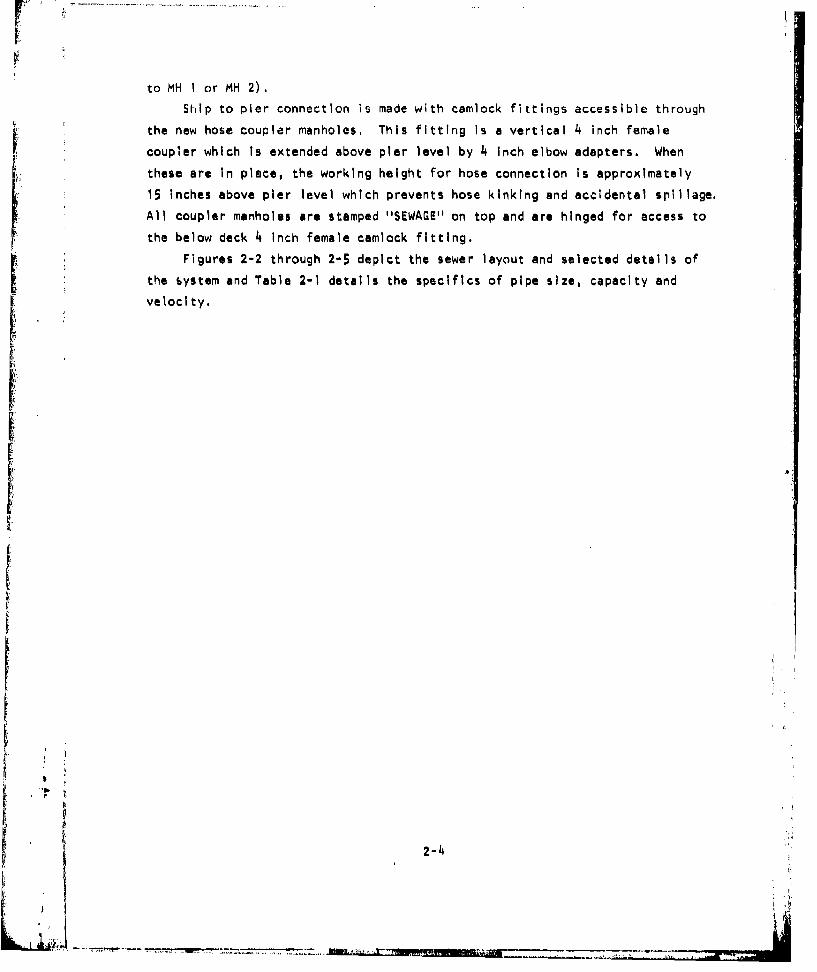
to MH I or MH 2).
Shlip to pier connection is made with camlock fittings accessible through
* the new hose coupler manholes. This fitting Is a vertical 4 inch female
coupler which is extended above pier level by 4 inch elbow adapters. When
these are In place, the working height for hose connection Is approximately
15 Inches above pier level which prevents hose kinking and accidental spillage.
All coupler manholes are stamped "SEWAGE" on top and are hinged for access to
the below deck 4 Inch female camlock fitting.
Figures 2-2 through 2-5 depict the sewer layout and selected details of
the system and Table 2-1 details the specifics of pipe size, capacity and
velocity.
I
•? ,,-4

rlil
LLL
00U
Z Lu
2-5
ikx:-Q

iit
"F6
LO
FJ z
000
cc
2- 6L
LU 4..:

MANHOLE TO PUMPING STATION
A AA~~~~ WET-ATAT ET
L RM
FIGUE 24. ierSewr L~ou
SEWER 0"2DI
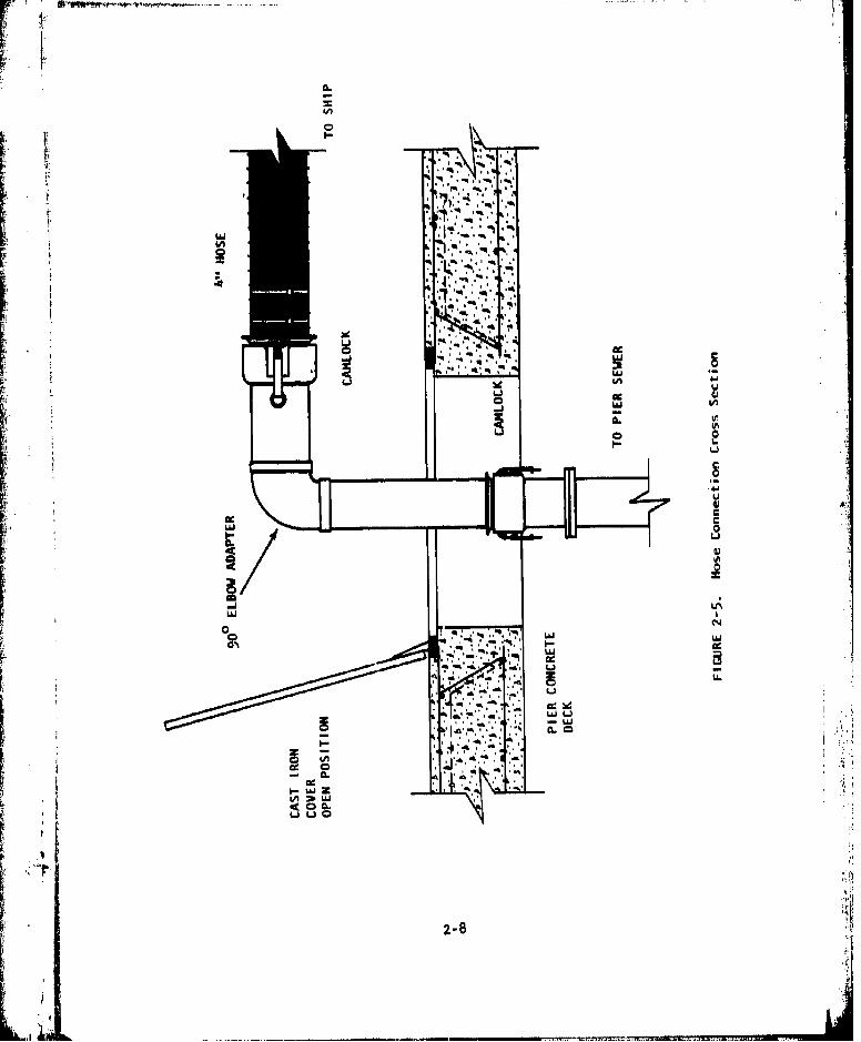
aac
IIf
0cw -
* ,~ *%*C,
de~q* -*****%
IAJ I
U4J
viA
cc.41 0 C
2-8 I.

m ~ LA0L R~ O* A N
N-l -W -V N 0 U% 6M P% - - -
6M . -%D4 VPýrfý N N 0 UW
uiA
- N
W -N
09 0U LA0
CM LAO -r.lt. 4-N 0 N N 00 LA c G
$A- - - - - N N - N N
LU 0
w4 LULUN
CjII S - 0 =
I2-
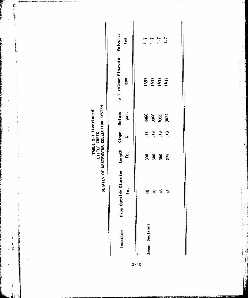
U.'
Li.
Ij-iLU
co- wi - - -
m -j
71 . C: 4.0 -
4A4
0-1

2.3 Pump Station
The existing station (Bldg. 3879) is east of the pier structures near
Helicopter Road (see Figure 2-6). It consists of a wet well room, wet well,(3I suction pipes, pump room, generator and motor room. The pump station due to
Its central location between the Little Creek piers and HRSD plant can also
serve as a sampling point and Intermittent and industrial waste removal sta-
tion, Coincident to receiving pier side sewage, the pump station also col-
lects sewage from buildings and other shore side structures through an exist-
Ing 18 inch diameter sewer.
The wet well Is accessed through a manhole cover and steel ladder ex-I tending approximately 17 feet down Into the wet well and terminating adjacent
to the 30 Inch diameter Inlet about four feet above the floor of the well."There are three pump suction Intakes, with minimum suction levels at five and
six Inches above the floor.
The pumps are of the stand-up centrifugal type with the following capa-
cities:
a. Pump #1 - 6" x 8'' 770 gpm @ 35.5 ft. T.D,H, passing 4 In. solids.
b. Pump #2 - 6" x 8" 1050 gpm @ 27.0 ft. T.DH, passing 4 In, solids.
c. Pump #3 - 8" x 10" 1350 gpm @39.0 ft. T.D.H, passing 4 In, solids.
The motors for pumps I and 2 are 15 H.P. @ 860 R.P.M., while pump 3 Is
operated by a 20 H.P. @ 860 R.P.M. motor, The pumps are operated by mechani-
cal float actuators located In an 8 inch float cage along the Interior wall
of the wet well. The preset control liquid levels for each pump are:
Level above floor level (ft)
Pump ON OFF
1 6.8 3.8
2 7.3 4.3
3 (backup for 6.8 3.8
pump #1)
2-11 "

F -~=-~cc
000
I--
lczz
1 41.t
I2-12p

The sewage flow from both pier and shore-side sewer lines join at MH-9
approximately 33 feet north of the pump station, see Figure 2-2. Combined
flow enters the wet well via the 30 Inch diameter cast Iron influent pipe.
The wet well room Is fitted with an 8 Inch cast Iron vent pipe. The
pump room has 1 1/2 Inch vent pipes Installed on each of the pumps and outlet
to the wet well side. All pumps are mounted on concrete pedestals and equip-pod with outlet check and gate valves, In addition , a sump pump is situatedbelow floor level and equipped with a 1 1/2 Inch outlet pipe discharging into
the adjacent wet well. Discharge from the three sewage pumps Is conveyed
through an 8 inch magnetic flowmeter and then Into a 10 Inch force main andsubsequently to a 16 Inch line joining the existing above ground cast Ironforce main located an the east side of Helicopter Road. The actual pumping
head is approximately 22 feet, Access for service and maintenance on the
pumnps, piping and valves Is by way of a stairway leading f~om the groundlevel motor room to the pump room below,
2.4 Hose Cleaning and Storage Building
The structure Is located north of the quay berthing areas adjacent to6th Street, see Figure 2-7. The facility has provisions for handling hosewashdown and rack storage, It Is placed so as not to Impede traffic on piers
and quays, and provides the advantage of a centrally located service and
storage station. The building Is outfitted with two hose washtables and adouble tier storage rack for 34 coils of collapsible sewage hose. For wash-down purposes, main supply steam and fresh water outlets are available. A
sloped concentration trench serves to collect washtable runoff and discharges
through a 6 Inch cast iron soil pipe joined to a buried clay pipe which leadsto an existing storm sewer, Personnel lockers, showers, laundry facilities
and toilets are available along with office space,
2
2-13 ,

.... ...
ri c
U.L.
-j at.
LL
tt
.U
2-14
ii
wl w
!lN
,• ,J'l•'• ........ ..... ...... • •,• • J•:••,l•-:•tJ•La.•',nr•• • ••

2.5 List Of Pertinent Plan Drawings
The following drawings detail key points of the pier side collection
system and are Itemized here for future reference:
TABLE 2-2 PERTINENT PLAN DRAWINGS
DESCRIPTION EFD DWG, NO. NAVFAC DWG. NO.
Location map, vicinity map andgeneral plan 114529 4014528
Wastewater collection system,plan and profile 114530 4014530
Wastewater collection systemplan and profile 114531 4014531Wastewater collection system,plan and profile 114532 4014532
Piers and quay wall details. 114533 4014533
Pier details 114534 4014534
Miscellaneous details 114535 4014535
Miscellaneous details 114536 4014536
Hose sanitation and storagebuilding 114537 4014537
Location maps, Index, andsymbols 1306108 81208
Plans and profiles HelicopterRoad 1306211 81211
Plans and profiles 6th Street 1306212 81212
Pump Station Helicopter Roadat 6th Street 1306216 81216
2-15
I A

3. SHIP WASTEWATER CHARACTERISTICS
Flushing water for shipboard sanitary systems Is provided by the salt
water firemein supply. As a result, the primary difference In ship verses
domestic sewage characteristics is the chloride level. Generally, studies
have shown that ship generated wastewater settles well and can be treated by
normal biological treatment processes, Table 3-1 presents the characterls-
tics of ship sewage from NAVFAC Design Manual DM-5. Also Included are the
results of wastewater tests on USS Portland (LSD-37) while at the quay wall
berth.
Most of the ships' CHT systems have garbage grinder discharges into the
collection systems. These tend to Increase the suspended solids, BOD, grit,
primary sludge and scum.
The monitorlng of volumes of ship generated waste have shown that in
actual practice the daily volume may be several times greater than the de-
sign standard of 60 gallons per man per day. These high flows are generally
the result of a constantly flushing salt water source into the CHT system.
Usually the ship Is unaware of this flushing. Even with this greater volume,
the fresh water dilution of Little Creek Cove should keep the chlorides beiow
11,000 mg/I.
3-1

F
.1I.
6m IN~
N
U
u.I
L- L
'A a aI
Uu
0 N-
0 0 0
3-2
. .

L4. SEWER CAPACITIES
The primary limitation to berthing arrangements at these NAB, Little
Creek piers Is the availability of shore power for shipboard requirements.
Also, the berthing areas 59-E and 59-W are solely dedicated to Navy Diving
School operations. This leaves the following active areas:
LOCATION NO. SHIPS (LPD, LSD, LST)
Quay Wall-west 1
Quay Wall-east 1
Dogleg 1
Pier 56* 1
Pier 57* 1
Pier 58, 1
*Power limitations preclude berthing two ships at each pier (east/west).
4.1 Ship Sewage Production
The largest ships, in terms of sewage production, which are berthed at
Little Creek, are LPD's, LSD's, and LST's. Table 4-1 presents a comparison
of DM-5 ship sewage generation estimates and field data taken from ships J
berthed at NAB. The DM-5 uses a 60 gallon per capita day estimate.
Recent field data has shown the daily rate to be closer to 144 gallons per
capita day. The field data shown In table 4-1 does not Include troops
aboard the ships.
4.2 Expected Total Ship Loads
The pier sewer loading flow rates are based on a maximum berthing situ-
at ion shown above. Table 4-2 estimates the sewer loading rates from maximum
berthing of 2 LPD's and 4 LSD's lising data ý.,alculated without troop complements.
4-1

The peak flow rate Is a function of the maximum pump discharge rate and the
average 24 hour rate for the multiple berthings of ships. For single ships,
according to DM-5, peak flow rates are a function of the design discharge
pump flow rates. What must be remembered about peak flow rate is that It
occurs for a relatively short duration of 3 to 5 minutes. During this pump-Ing cycle of about 400 gallons per ship, the sewer piping would have to fillup before the system would exceed Its full pipe flow capacities. Table 4-2
shows that the shore side sewer system Is capable of handling the average
24 hour flow rates but some sections may become pressurized during extreme
peak flows for very short durations. It is unlikely that all peak flows
will occur simulataneously, and field testing has shown that the peak flow
rate from an Individual ship Is significantly reduced by discharge through
the collapsible sewage hose.
r
4-2

thN w
La.
z C LA -W
atJ LACc OZ6-
I- -
06 0
L6. 0.)
AI -.ILn
LU 1 -
LiJ
-L N q0 1. N
a. q A. a.: 0 V
I-4 LPLLf
UM 0II
y -
LJ 0)
_ CLL VI f^
4-3

U-' Lr Ln -gw -.:r
%0%0O LA LA% L r LA U
-au
rum- m. LALAl. r
14 LA 6% 6M 6%
0W z -00
I- -
00
N 1.0
W 0o
I- >h O '.
00
Ln 0 M th 0
mr. 0
-4-4

5. SEWER PROCEDURES - NORMAL
5.1 Connecting Ships
The NAVFAC ship to shore hose handling MO-340 provides detailed tasks
for ship to shore sewage connections for a variety of ships and circumstances.
The following provides additional guidance for making connections to the
Little Creek piers.
The first step In making a successful ship to sewer hookup is knowing
the requirements of the ship for shore side supplled sewage transfer hose and
fittings. A log book describing the requirements and pier use hi'tory for
each ship should be developed and maintained as more and more ships begin
using pier sewers. This log provides a ready reference to the hose handling
crew to provide the proper length of sewage transfer hose and fittings for
each ship request. A recommended format Is shown In Figure 5-i.The shore side hose handling crew requires at least two men, It is the
responsibility of the shore side crew to meet with the ship CHT Officer toInsure that his man are available and understand how to make the ship connec- .
tlons, At least three men are required aboard ship for this task. The ship
hose handling crew are not expected to handle sewage equipment on the pier,
Safety, health and clothing requirement for sewage hose handling are
detailed in Section 7 of this manual.
a. Sufficient hose lengths are laid out on the p!er and connected with
the female hose end tied to a heaving line for passing to the ship,
The female end should be plugged at this time. This brass plug Is
recovered from the ship before the shore hose handling crew departs.
b. The pier sewer risers are located under hinged cast Iron covers in
the pier deck. The pier sewer is a continuous gravity system. The
characteristic of gravity sewer systems is that collection piping
does not run full and Is, therefore, not pressurized. As a result,
-5-
L

SHIP LOG SHEET
SHIP:,DISCHARGE RISERS/SIDE:HOSE SIZE:EXPECTED GPD:DIRECT HOSE FLUSHING AVAILABLE: YES NO
CONNECT ETHRISER HOSE DISCONNECT TOTAL
DATE EtH NO. LENGTH DATE P REMARKS
F IGURE 5- 1 Log Sheet
5-2
~ ~ . . . .;';,

the sewer riser fittings do not require valves and are secured
only by the 4 Inch camlock brass plug. Pumping tests on the quay-
wall system have shown that these pier risers are not pressurized
during ship pumping. However, venting does occur through open
risers and the operator may notice "breathing" from the open
piping.
c. Because the pier riser fitting is set below the pier deck level, It
is necessary to connect a 90 degree adapter fitting to the pierriser. This four inch camlock adapter fitting rises 15 Inchesabove the deck surface to connect with the ship sewage transfer
hose to prevent kinking of the hose, A photo of this sewer connec-
tion is shown In Figure 5-2.
d. To minimize chances of an accidental sewage spill, the shore crew
must Insure that the hose connection to the pier sewer riser is
completed prior to the ship deck riser connection. Because the
pier sewer cover does not lay flat on the pier decking, the hose
connection Is possible only from one direction. In most cases theIT adapter riser should be turned so that the connection Is parallel
to the length of the pier. By connecting the hose In this way the
chances of hose kinking are reduced, Because of the problem with
the pier riser cover It may be necessary to go to the next avail-
able riser using additional lengths of sewage transfer hose.
e. The open cover to the pier riser provides an unguarded opening
through the pier decking. A safety barricade should be placed
over this opening to clear the riser adapter, See Figure 5-3. pf. The last task for the shore side hose handling crew is to arrange
the hose along the pier to minimize hose kinking, contact with
steam lines, and away from the vehicle traffic aroas, The hose
should be examined for leaks as the ship begins pumping. If gas-
kets or hose sections then require replacement, procedures for hose
flushing and draining as described In the following section should
* •be followed before making repairs.
5-3
"i5
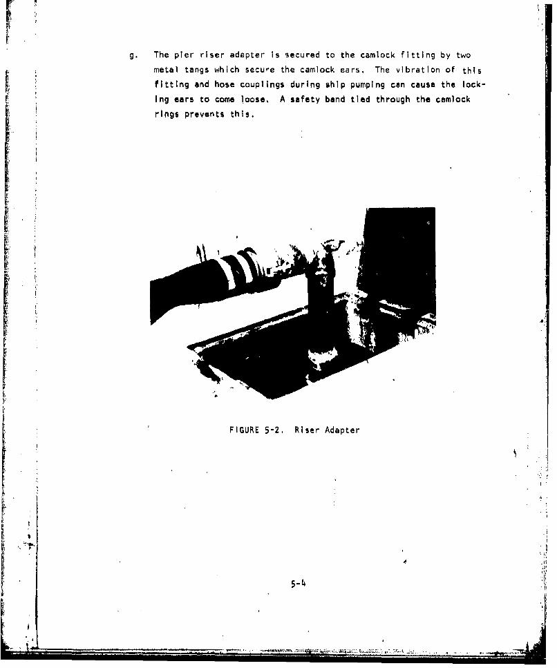
g. The pier riser adapter Is secured to the camlock fitting by two
metal tangs which secure the camlock ears. The vibration of this
fitting and hose couplings during ship pumping can cause the lock-
Ing ears to come loose. A safety band tied through the camlock
rings prevents this.
k
II
FIGURE 5-2. Riser Adapter
S4 j
5-4 :iAAr
I I

r1
Ii
[ a;t
i ~FIGURE 5-3. Safety Barricade .
A
5-5 ~

5.2 Disconnecting Ships
Detailed procedures for disconnecting sewage transfer hose from ships
and other vessels Is described In NAVFAC MO-340, Chapter 8.
a. The shore side hose handling crew should check with the shipboard
personnel to Insure that disconnecting procedures are understood
and coordinated. At this time plugs for the four Inch camlock
hose should be provided to the shipboard crew. These will help
prevent spills as the hose is lowered.
b. Ships have been Instructed to flush the sewage transfer hose with
salt water from the firemain connection Installed In their CHT
discharge piping. This flushing of the hose for 10 minutes is all
that is usually required to clean sewage transfer hose. The shore
crew should check with the ship to be sure that this flushing has
been accomplished. Some ships are unable to provide direct salt
water flushing. The shore side crews should be aware If the ship
is unable to provide properly flushed hose. All ships soon will be
fitted with this direct salt water flushing capability.
c. After flushing, the ship disconnects from their deck riser and
drains the hose by allowing It to vent through the open fitting.
At this time the shore crew should raise the low spots of the hose
to allow It to drain Into the sewer, Only after all draining is
accomplished is the hose plug installed on the open hose.
d. The hose Is disconnected from the pier riser only after It has been
lowered to the pier. Hose, caps and plugs should be removed before
the hose is coiled and placed In storage. This will allow the hose
to vent while on the rack.
a. The pier riser adapter is removed whenever the sewage hose Is dis-
connected and the sewer riser plugged when not in use.
f. While the hoses and fittings are laid on the pier, the hose han-
dlers should inspect all fittings and hoses for damage and separate
4? them for maintenance. Properly flushed sewage hose can be
5-6
i -4

immediately used for other ship connections without further clean-
Ing or maintenance.
5.3 Small Craft
Pier sewers will accept sewage from small craft and Sewage SWOB barges.
At this time there has been little experience with procedures for these craft,
They will be developed and included In NAVFAC MO-340.
5.4 Stwage Transfer Hose
There are several types of sewage transfer hose available for large
ships, submarines and small craft. Large ships with CHT systems usi standard4 inch camlock fittings on 4 inch hoses. Submarines use a 2 1/2 sewage hose
with camlock fittings and small craft use 1 1/2 inch camlock fittings and
hose. Only sewage transfer hose has the camlock fitting which prevents its
use In other utility services. The hose Is clearly marked "'SEWAGE",
Sewage transfer hose comes In two designs. Originally all facilities
were outfitted with the 4 Inch collapsible hose (50 foot--130 lbs. MIL-H-
20176). A rigid wall, wire reinforced gravity transfer hose is presently
available (MIL-H-20176D). Five years of continuous service life for these
hoses should be expected.
The collapsible hose Is suitable for all sewage transfer operations.
However, the operator will note that It kinks easily and can shut off the
flow from the ship. Additional care must be taken to prevent hose kinking,
particularily with rise and fall of the tide. Additional 90-degree elbows,
temporary hose saddles, and tie-offs may be necessary. Ship hose connections
should be regularly Inspected by utility crews to insure that kinking has not
occurred.
As ships are pumping sewage, the collapsible hoses will pulse, This
pulsing can quickly cause chafing of the hose and severe damage without
proper precautions. This Is particularly severe where the hose passes over
sharp concrete pier curbing.
5-7
i I '

6. SEWER PROCEDURES - EMERGENCY
As the pier sewer systems become a regular part of ship provided utility
services, these pier sewers must be kept operating with a minimum of service
disruption In the event of system failure. This section provides some guld-
ance as to the problems that may be encountered In repairing the pier sewer
system and some methods to restore pier sewer service as quickly as possible
with a minimum of disruption to shipboard operation.
6.1 Sewer Line Break
The pier sewer systems are Interconnected to a common sewer main and
lift station. This Interdependence complicates the effect of a sewer line
break or major leak throughout the entire system. Pier sewer breaks have
occurred on similar pier sewer systems. Emergency repair procedures shouldbe well understood and rehearsed before they become necessary, It should be
noted that most of the pier sewer piping Is submerged at high water. Thus
* the greater cause of concern Is the uncontrolled entry of sea water into thepier sewer system to the pumping station. To comply with discharge permitregulations, the gravity overflow bypass at the pumping station and a sluice
gate valve were removed. As a result It is difficult to Isolate the pumpingstation In the event of a major sewer line break.
Pier sewer breaks may occur for the following reasons:
1. The underpler sewer Is hung close to the pier fonder piling and
can be damage6 from docking impacts.
2. Fender camels can become wedged under the pier sewer piping and
crack the piping as they rise with the Incoming tide.
3. Gradual saltwater corrosion can weaken sewer plie flanges and
eKpansion joints.
6-1 A
Ut

4. Seasonal ground settling can cause buried pipeline cracks, result-
Ing in infiltration of ground water. These cracks would not usually
result In massive sea water !ntruslon but should be Identified and
repaired to limit unnecessary treatment plant processing of ground
water.
If a major break occurs In the pier system it will be necessary to
physically Isolate that pier sewer from the rest of the system. A pier
sewer line can be most easily isolated with the use oF a sewer plug, Typical
sewer plugs are shown in the photos. Figure 6-1 Is an air Inflatable bladder
type plug. Figure 6-2 Is a mechanical screw expandable plug, Figure 6-3 Is
an air Inflatable rubber plug.
The most common pier sewer plug required will be the 10 Inch plug for
the ductile Iron pipe connected to the manhole from the pier sewers. It may
be necessary to delay the use of the sewer plug until a suitable tide level
occurs. Figure 6-4 shows various tide levels with respect to pier piping
and the deepest manhole,
The following sequences should be followed by Public Works Department'
utility division In dealing with a major break:
1. Upon notification of discovery of a pier sewer break the ship up
line of the break should be notified to secure sewage pumping. At
the same time, Port Operations should be notified to provide sewage
SWOB barges (if available) for the ship or alternative pier berths.
2. Notify HRSD of Increased saltwater content of wastewater. This
will give them opportunity to divert some of the waste and provide
additional holding and mixing time.
3. Identify appropriate manhole for sewer plug. Prepare the necessaryequipment for manhole entry and notify Fire Department to provide
a gas-free inspection of the manhole.
4. Determine appropriate tide level and time from Port Operations when
sewer pipe may be accessible from the manhole.
"5 Install sewer plug.
6-2
SI Ii IM

F IGURE 6-1. Air Inflatable Bladder Plug
FIGURE 6-2. Mechanical Screw Expandable Plug
6-3
1.*4
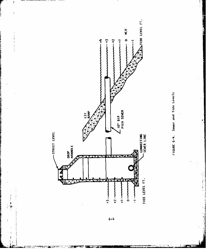
LL.
-J
z LI
-i
Lp L6U
.r rz (N 0 -.
6-44

FIGURE 6-3. Air Inflatable Rubber Plug
• FIGURE 6-5. Mechanical Pipe Patch
..6-5
6. Notify HRSD of reduced saltwater content In wastewater.
After Initial emergency plugging It may be possible to take some correc-
tive action to provide a temporary fix for the broken pier piping. Small
leaks and breaks may be repaired by use of a mechanical pipe patch as shown
in Figure 6-5.
The repair of broken pier sewer piping should be treated as an emergency
and contracted accordingly. Sources of repair pipe and contractors with
suitable equipment should be Identified beforehand.
Sections of pier piping may be usable If the Isolation plug Is Installed
at the site of the pipe break. This will allow at least a portion of the
pipe sewer to be used and additonal sewage transfer hose can be provided to
the ship so It may pump to the nearest available sewer riser,
it is possible to run additional hose lengths from the ship to the near-
est available manhole. The ship pump out time will be increased only slight-
ly.
Waterfront operations must be kept Informed of pier sewer repair condi-
tions so that they may provide alternative berthing arrangements. Ships
equipped with sewage transfer systems will be required to berth at piers with
collection capability.
6.2 Industrial Waste Intrusion
Pier sewer systems have been used as a convenient but Improper way to
dispose of a variety of Industrial waste from ships. These have Included oil
wastes, paint and paint thinners, boiler cleaning compounds and a variety of
shipbcard hazardous materials. These wastes are usually first noticed In the
sewage wet well and can be traced via the pier sewer line to the suspected
source. If intrusion Is noted, action to remove the material must be taken.
HRSD should be Immediately notified so that they can monitor their Influent
and take action to protect their treatment process. PWD has two pump trucks
available equipped with suction hose pumps and a storage capacity that can
be dispatched to the sewer wet well. If evidence of hazardous material
exists in the sewers they must be flushed by fire hose while collecting the
material at the sanitary wet well through the access manhole.
6-6,-!
Industrial waste material and flammable liquids enter the pier sewer
piping only through the pier riser connections or directly Into the manholes.
Material spills Into open areas that reach storm drains will not reach the
pier sewer system. In most cases these drains discharge into the harbor.
in the event of flammable material entering the sewer system, the NAB
Fire Department can be notified and requested to Inject aqueous film-forming
foam (AFFF) into the pier sewer piping, manholes or sanitary wet wells as
necessary. AFFF Is a toxic material and its use should be regulated to pre-
vent damage to the systems at the HRSD plant. Also, ships which are required
to regularly test AFFF mixtures should be directed to alternative disposal
methods,
6.3 Electric Power Failures
The pump station (Building 3879) Is equipped with a 75 KW emergency gen-
erator that Is automatically activated as a result of base power failures,
This emergency power will provide sufficient pump power for the requirements
of the pump station,
It is a usual practice of ships berthed at Little Creek to use shore
supplied power. In the event of shore side power failure the ships will
change to onboard emergency generators to provide partial ship power. It is
the usual practice, however, that sufficient power Is not made available to
ship sewage transfer systems (CHT). Therefore, ships will not be usually
pumping to thepler sewer system In the event of shore side power failures,
If the pump station emerqency power fails, ships connected to the system
should be requested to divert their systems or begin holding until the power
failure problem has been corrected,
6.4 Sewage Spill Procedures
Sewage spills on open areas of piers most frequently occur from sewage
hose failure, Improper hose connection procedures or vehicle damage to the
pier riser fittings. The first concern in responding to a sewage spill Is
to keep personnel away from the area. Stop the source of the spill andflush down the area as quickly as possible, More detailed procedures are
discussed in the following health and safety section.
6-7
;=6-7
i4

6.5 Emergency Notifications
Any of the above emergency situations require the notification of the
following:
1. Port Operations Duty Office Tele: -7791
2. PWD Duty Officer -7238
3, Hampton Roads Sanitation District
(HRSD) Chesapeake-Elizabeth Plant 464-6448
6-
[i
I
• ~6-8 :
I'-- - - - -.. ,!.
7. HEALTH AND SAFETY
The operation and maintenance of ship to shore sewage transfer systems
Is no more hazardous than any waterfront operation. The safety and health
precautions for this work are mostly a common sense approach. Historically,
workers in the maintenance of sewer systems and the operation of treatment
plants have enjoyed an excellent health and safety record. Workers with the
ship to shore sewage transfer system should be aware of the following health
and safety precautions.
7.1 Health Precautions
-Coting. The following list of clothing is that suggested for
most routine operation and maintenance procedures. Clothing
should be washed frequently and a spare set of work clothes or
coveralls available In a locker to provide a fresh change of
clothing If necessary. No special segregation of this clothing is
necessary for washing and can be washed with regular home laundry
loads or In the machines available at the hose cleaning facility.
Hardhat. An approved safety hardhat is required for all work
plerside.
Work clothes. Regular work clothes or coveralls are all that
is req'jlred for exterior clothing and working with sewage
transfer hose. Coveralls and waterproof aprons are recommend-
ed when cleaning hoses or working with wet equipment.
Rubber gloves. A short pair of heavy duty rubber gloves Is to
be worn while handling sewage hose and equipment.
Work shoes. Steel-toed work shoes must be worn at all times
while handling sewage transfer hose and fittings and perform-
ing maintenance tasks. Steel-toed rubber boots should be worn
7-1
iI
Lr
while making hose disconnects or when In wet sewage environ-
ments. (wet wells, manholes or sewage spills).
Washing up The most Important health precaution to regularly
follow Is remembering to wash hands and face after handling sewage
equipment prior to eating, smoking, or drinking. This must become
a regular habit of all sewage transfer workers. Hand washing and
shower facilities are available in the hose cleaning building,
Health records The base dispensary should be requete• to mark
the health records of personnel working with sewage transfer equip-
ment with the following notice: "Occasional Contact With Sewage".
Shot records BUMED has recommended that the normal series of
Inoculations be maintained for all personnel working with sewage
equipment. These are tetanus, typhoid, and polio. These Inocula-
tions, if kept up to date, should provide a sufficient level of
protection to the worker. Workers should be particularly careful
with open cuts to keep them clean and dry to prevent Infection. The
dispensary should be visited for treatment for any infections, sew-
age In the eyes, or any abnormal health condition that may occur.
Potable water connections Personnel working with sewage transfer
equipment must not then also make potable water connections. If It
Is necessary to connect to a water hydrant to hose down an areafrom a sewage spill, a different man should be called In to make
this connection and handle the fresh water hose.
7.2 Safety Precautions
Pier operations The shore crew for sewage transfer hose cunnec-
tions and disconnection procedures requires at least two men. Thecoiled hose lengths weigh approximately 150 pounds with the brass
fittings attached. It is therefore necessary to Insure that at
least two men lift the heavy coils on and off the truck. Hardhats
are necessary while on the piers particularly when the hose Is
raised and lowered to the ship. The sewage transfer hose is
7-2
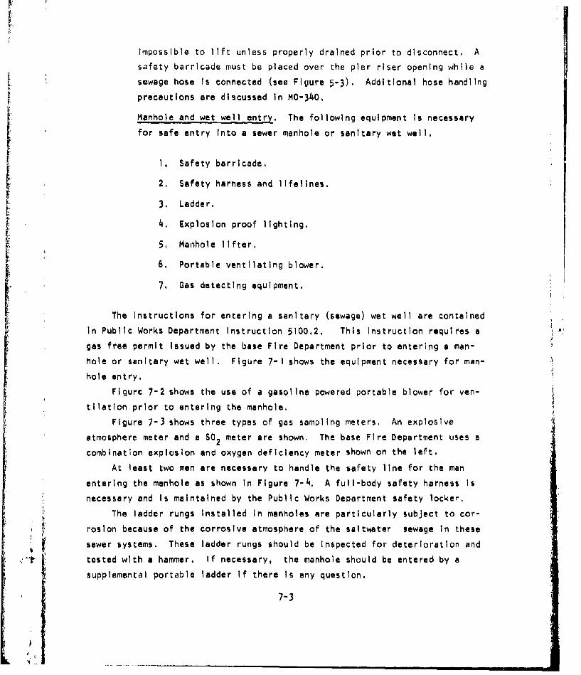
impossible to lift unless properly drained prior to disconnect. A
safety barricade must be placed over the pier riser opening while a
sewage hose Is connected (see Fijure 5-3). Additional hose handling
precautions are discussed In MO-340,
Manhole and wet well entry. The following equipment Is necessary
for safe entry Into a sewer manhole or sanitary wet well.
1. Safety barricade.
2, Safety harness and lifelines,
3. Ladder.
4. Explosion proof lighting.
5 Manhole lifter.
6. Portable ventilating blower,
7. Gas detecting equipment,
The Instructions for entering a sanitary (sewage) wet well are contained
in Public Works Department Instruction 5100.2, This Instruction requires a
gas free permit issued by the base Fire Department prior to entering a man-
hole or sanitary wet well. Figure 7-1 shows the equipment necessary for man-
hole entry.
Figure 7-2 shows the use of a gasoline powered portable blower for yen-
tilatlon prior to entering the manhole,
Figure 7-3 shows three types of gas sampling meters, An explosive
atmosphere meter and a SO2 meter are shown. The base Fire Department uses a
combination explosion and oxygen deficiency meter shown on the left,
At least two men are necessary to handle the safety line for the man
entering the manhole as shown In Figure 7-4, A full-body safety harness Is
necessary and is maintained by the Public Works Department safety locker,
The ladder rungs Installed In manholes are particularly subject to cor-
roslon because of the corrosive atmosphere of the saltwater sewage in these
sewer systems. These ladder rungs should be Inspected for deterioration and
tested with a hammer. If necessary, the manhole should be entered by a
supplemental portable ladder If there Is any question.
7-3
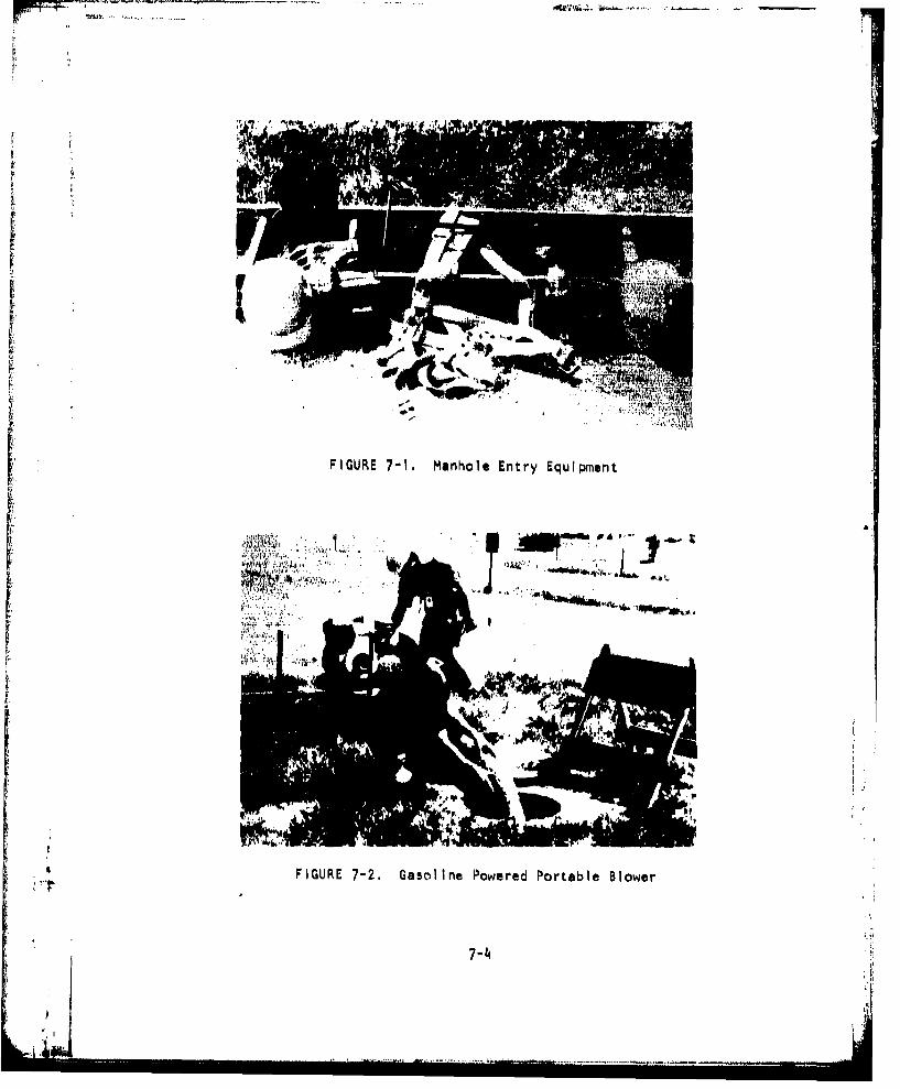
FIGURE 7-1. Manhole Entry Equipment
FIGURE 7-2. Gasoline Powered Portable Blower
7-4

0U
LL.
6a.
7-

The presence of explosive and toxic gasses and an oxygen deficient atmo-
sphere in manholes should be of constant concern to sewer maintenance workers.
These gasses cannot be detected by smell and must be regularly tested by the
proper sampling meter. If there is any doubt on the condition of the atmo-
sphere within a confined manhole, force ventilation should be provided.
7.3 Sewage Spill Clean UŽ
Sewage spills are most likely to occur around the pier sewer connection
riser and immediate pier deck area. These are usually the result of insuffi-
cient hose drainage prior to disconnect, leaking hose gaskets, hose rupture
or a ship pumping through a disconnected sewage hose. The basic procedure Is
to flush the area clean. The following procedures should be used and adapted
for various sizes of sewage spills.
-- Secure source of spill.
-- Close off area to unnecessary traffic and personnel.
-- Flush area with fire hose - salt water from ship hose Is preferred.
-- Use disinfectant or detergent to cut odor or grease If needed.
(Use a dry phenolic compound or any stock detergent)
-- Flush area again,
-- Open area to regular activity.
The disinfectant recommended in MO-340 is a disinfectant, germicidal,
fungicidal concentrate (phenolic dry type) stock number 6040-00-753-4797.
HTH chloride is not recommended for use around piers or when it may come In
contact with grease or oil.
7-6

S8. MAINTENANCE
The maintenance of pier sewer systems will become part of the regular
sewerage system maintenance on the base. The design and installation of the
pier sewer system Is similar to that of domestic sewers. However, there are
some differences and precautions to be noted in the maintenance of this
system. The following sections highlight particular problems with pier sewer
maintenance.
8.1 Regular Maintenance
The increased chloride level of ship generated waste will aggravate the
effects of corrosion on the pier sewer system, More rapid deterioration will
occur In the cast Iron pipe sections, mechanical joints and manhole ladders.
Regular daily Inspections of pier sewer system Is important to Insure
continued trouble-free operation. The following daily inspections should be
made:
a. Sewage transfer hoses from ships pumping Into the pier sewers
should be inspected for tight camlock connections, leaks around
gaskets and fittings, kinks In the collapsible hose, excessive
weight from c&.enary bends and contact with hot steam lines and
hose chafing.
b. While ships are pumping Into pier sewers, whenever possible,visual
inspection of the exposed under pier collection lines should be
made to observe any damage or leaking. This Inspection Is best
accomplished at low tide when all the under pier piping will be
exposed,
c. The pumping station wet well should be examined for evidence of oil
or excessive grease buildup, If oil or chemicals are present, pler
sewer manholes should be examined to see if the source of the
8-1

pollutant can be isolated.
Less frequent inspections should be made at least weekly or as they
occur In the following areas.I
a. When no ships are using the pier system a manhole should be opened
and any sewer flow should be observed to determine the rate of
infiltration. This would be best accomplished during high tide at
maximum submergence of the pier piping.
b. As damage to pier fender piling occurs the under sewer pipingshould be Inspected for damage and evidence of leaking.
8.2 Regular Sewer Maintenance
The majority of the east side pier system has full pipe flow velocities
less than the design standard In DM-5 of 2.5 feet per second. Table 2-1
lists the velocities for each section of sewer pipe. It should be noted that
most of the pier system has velocities in the range of 1.5 feet per second.
As a result, these portions of the sewer system may quickly accumulate solids
buildup as the low flow rates allow the sewage to settle in the pipes, As,he frequency of pier sewer use increases, at least quarterly inspections of
these sections of the sewer system will be necessary to determine the rate
of sludge buildup, Inspections of manholes should include observation of
excessive oil, the amount of sewer gas, infiltration and pipe blockage, As
sewer solids buildup occurs line flushing and cleaning will be required.
Extreme care should be taken during excessive cold weather periods which
may cause line blockage from ice formation. It Is the nature of CHT opera-
tion that the pier sewer is regularly dosed with about 300 gallons of sewage
from one pump firing, This dosing will occur very Infrequently, particularly
during the coldest hours in the early morning, The flow from the ship Is not
constant and this intermittent loading may facilitate rapid ice buildup in
the gtewer lines. Until sufficient experience with cold weather operations is
gained, extreme care should be taken when the system is used in cold weather,
The pier piping should be inspected yearly for damage and the condition
of exterior coating. Pier risers along with camlock fittings, gaskets, plugs
8-2
S ': |•W • • • •' .. . • • "= •T• ¢'• • "7;• ! " •:'•.... . • " ' :Ji

and riser manhole covers should be inspected and maintained as necessary.
Working camlock gaskets in the pier risers and hose require replacement about
yearly to maintain tight leak-free connections.
8.3 Hose Maintenance
Regular maintenance procedures for sewer transfer hose are outlined In
MO-340. Normal flushing of sewage hose with ship saltwater flushing connec-
tions will provide sufficient cleaning of the sewage hose prior to disconnect,
The most Important maintenance function to be performed on the hose Is rou-
tine Inspection prior to hose storage. Hose with evidence of leaks or ex-
cessive abrasion should be removed from service and the bad section cut out
by shortening the hose length, If possible. For hose In continuous service
MO-340 recommends a hydrostatic pressure test to 100 psi at least every 90
days.
I
tA
8-3 :

SHIP WASTEWATER COLLECTION SYSTEM
STANDARD OPERATING PROCEDURES
FOR
PIERS 20, 21, 22, and 23
U. S. NAVAL STATION,
NORFOLK, VIRGINIA
- i ~~, -. --- ,. .nl-

iI!
TABLE OF CONTENTS
U. S. NAVAL STATION
NORFOLK, VA.
LIST OF FIGURES ...................... .................. III
LIST OF TABLES. ......... . .. ....
1. INTRODUCTION. . ................ .... ,. . 1-11.1 Background ... ,.............. ... . 1-1
2. FACILITIES AND EQUIPMENT DESCRIPTION . . .... ... . 2-1
2.1 General . . . . . .. . . . .... . ,. . ,. . 2-12.2 Pier Sewers . . . . . . . .. . .. . . . , . . 2-12.3 Pump Station . . . . . . . . . . .... . . .... 2-32.4 Hose Cleaning and Storage Building . .II, .. ,. 2-122.5 List of Pertinent Plan Drawings . ..... .. . 2-12
3, SHIP WASTEWATER CHARACTERISTICS . . ..... .... .. 3-1
4. SEWER CAPACITIES . . . . . .. .. . . ....... . 4-1
4.1 Ship Sewage Production . ... ... .. . .. 4-14.2 Expected Total Ship Loads .. . . . . . .. . . 4-1
5. SEWER PROCEDURES - NORMAL .......... ......... .... 5-15.1 Connecting Ships ........ ... .. ... . . 5-15.2 Disconnecting Ships .................. ............. 5-45.3 Small Craft. . .. ............. ................ 5"55.4 Sewage Transfer Hose ....... ............... 5-5
6. SEWER PROCEDURES - EMERGENCY ............. ............ 6-16.1 Sewer Line Break ................ ............. 6-16.2 Industrial Waste Intrusion ... ........... ....... 6-36.3 Electrical Power Failure ....... ... ............ 6-4
6.4 Sewage Spill Procedures ............. ............ 6-46.5 Emergency Notifications . . . . . . . . . . . . . . .. 6-5
7. HEALTH AND SAFETY . ................ ................ 7-17,1 Health Precautions ....... ................... 7-17.2 Safety Precautions ................. 7-27.3 Sewage Spill Clean Up ........ ................. 7-3
8, MAINTENANCE. ............... ............ .... . . .. 8-18.1 Regular Maintenance ..... ........... . . . . . 8-18.2 Regular Sewer Maintenance ... .............. . 8-28.3 Hose Maintenance ....... ................... .. 8-3
L ;I,
i . L ,1I
Ii* - . - - - - --N

LIST OF FIGURES
Page-
2-1 Sewer System Schematic . .. . . .. . . . . * . . .2-2
2-2 Receiving Sewer Layout ................... ....... . 2-4
2-3 Pier Sewer Layout ......... . .. ...... ... . 2-5
2-4 Pier Riser Details ..................... ......... . 2-6
2-5 Cleanout / Sewer Detail]...... .2-7
.-6 Hose Connection Cross Section . . 2-8
2-7 Pump Station ................. .............. 2-14
5-1 Ship Log Sheet ....................... .5-2
6-1 Air Inflatable Rubber Plug .... 6-26-2 Mechanical Screw Expandable Plug....... . .. .. ....... 6-2
LIST OF TABLES _
2-1 Details of Wastewater Collection System ............. ..2-92-2 Pertinent Plan D-awings .................... 2-12
3-1 Ship Wastewater Characteristics ..................... .3-2
4-1 Planned Berthing FY 1980 ....... ................ 4-2
4-2 Summary of Planned Berthing ..... ................ 4-3
S S
:!i

I. INTRODUCTION
This manual presents standardized operating guidelines for shoreside
support of the ship wastewater collection system for piers 20-23, Destroyer
and Submarine Piers, at the Norfolk Naval Station , Norfolk, Virginia. The
sewers on the piers join and drain into a single pump station (#3). By con-
sidering these piers as a single system, as described In this manual, the
user will be better able to understand their common operating procedures as
well as their Interaction during emergency situations.
1.1 Background
The Naval Station Pier Sewer System was installed by the 1974 MILCON
project to enable the base to comply with the Federal Water Quality Act of
1972 as specified in DOD Directive 6050.4. Details of the Navy's compliance
are given In OPNAV Instruction 6240-3E for both the ship and shoreside re-
sponsibilities In ship wastewater collection and transfer.
The pier sewers are designed to collect shipboard generated wastewater
from naval vessels, Surface vessels and small craft either collect and hold
wastewater with Installed Collection Holding and Transfer (CHT) systems or,
on smaller vessels, with Marine Sanitation Devices (MSD) which provide some
onboard processing. The majority of vessels using the pier sewers at the
Naval Station will have CHT systems. These systems will be Installed on
nearly all Navy surface vessels by April, 1981. Properly equipped vessels
are required to operate their systems prior to that date.
The operation of CHT systems with pier sewers has been well documented
from field tests and extensive operating experience at other naval port
complexes. The procedures outlined in this manual are field-proven from this
rapidly growing base of prior experience as the number of activities accept-
* Ing shipboard wastewater quickly Increases.
General operating guidance for ship to shore sewage transfer hose
1-1
.1

connection, cleaning, and sanitation are documented in NAVFAC manual MO-340,
Additional Information and support Is available from NAVFACLANTDIV Environ-
mental Division and Public Works Utility Departments of other naval activities,
This manual briefly applies the recommendations In MO-340 specifically
to the Norfolk Naval Station and is organized Into the following sections:
2. FACILITIES AND EQUIPMENT DESCRIPTION. Discusses the general pur-
pose, layout, characteristics of ship generated wastewater, and
details of pier piping layout.
3. SHIP WASTEWATER CHARACTERISTICS. Presents Information on the
contents of ship generated waste.
4, SEWER CAPACITIES. Presents data for the expected loading capacity
of the pier sewer system from maximum planned ship berthing arrange-
ments.
5. SEWER PROCEDURES - NORMAL. Discusses the additional procedures
to be followed when connecting or disconnecting ships to these
pier sewers.
6. SEWER PROCEDURES - EMERGENCY, Presents the emergency procedures
to be followed for specific emergency conditions and recommended
repairs.
7. HEALTH AND SAFETY. Provides personnel health and safety precau-
tions In working with sewer transfer equipment and Its maintenance,
8. MAINTENANCE. Presents a daily and regular maintenance schedule for
the pier sewer system.
1-2
2. FACILITIES AND EQUIPMENT DESCRIPTION
2,11 General
The collection and transportation of ship generated wastewater to
shoreside treatment facilities involves several interrelated systems and
activities. These are:
SYSTEM ACTIVITY
a. The shipboard sewage Collection,
Holding and Transfer (CHT) system. Ship
b. Ship to shore sewage transfer
hose and fittings. Ship/PWC
C. Pier sewer installations. PWC
d. Sewage pumping stations, PWC
e. Sewage treatment plants. HRSD
Figure 2-1 Is schematic of the ship to shore wastewater transfer compo-
nents. Wastewater Is collected and held by the ship's CHT system and pumped
to shore through sewage transfer hoses to the pier sewer, The wastewaterflows by gravity from the piers to other larger buried sewer lines which are
connect other pier sewers. The sewage from all piers in the system flows to
a single wet well and pump station. The pump station periodically pumps
the collected ship sewage through a pressurized force main to the HRSD
Army sewage treatment plant. The treated water Is then discharged Into
the receiving water at the plant's outfall,
2.2 Pier Sewers
The pier sewer system Identified as piers 20, 21, 22, and 23 at the ,
Norfolk Naval Station consists of 6,100 lineal feet of 10, 12, 15, 16, 18 inch -4
2-1
Li .4

rC
uj 2 i
-LJ
I..cc
Iu
ILa tA1viv
LUU
0. 2-2
diameter ductile iron and viterous clay pipe, manufactured according to spec-ifications as detailed In NAVFAC Design Manual (DM-5). The total full
volume of the system including collectors and main conduit is approximately
38,000 gallons with Individual section full capacity flow rates ranging from
404 gpm to 1,908 gpm. Full capacity velocities of the larger 18 Inch dia-
meter sewer pipe sections leading to pump station #3 are 2.3 fps. Velocities
occurring In the suspended pier piping range from 1,7 to 1,8 fps.The system Is of the gravity sewer type consisting of sloped sections
of 10 and 12 Inch diameter pipe suspended below each pier and Intersectingto lead to the pump station. Velocities throughout the system fall below theD1-5 minimum requirement of 2.5 fps.
Each pier has two discrete main sewer lines each consisting of 9 pairsof ship to shore hose connection points. Also, each pier Is outfitted withclean-out access points to facilitate flushing of the pier systems.
Ship to pier connections are made with camlock fittings accessible
through the new hose coupler manholes. This fitting Is a vertical 4 Inchfemale coupler which is extended above pier level by 4 Inch elbow adapters.All coupler manholes are stamped "SEWAGE" on top and are hinged for accessto the below deck 4 inch female fitting, Figures 2-2 through 2-6 depict thesewer layout Including the details of the elbow adapters. Table 2-1 detailsthe specifics of pipe, size, capacity, and velocity,
2.3 Pump Station
The pump station is located on "B" Avenue near pier #22, The station
receives sewage through an 18 Inch sanitary sewer leading from manhole #1
at the west side of the building. There are three centrifugal pumps with
rated capacities as follows:
Pump #1 " 800 gpm
Pump #2 - 2,100 gpm
IPump #3 - 2,100 gpm
Pump #1 serves as the main duty pump for the system, Pumps #2 and #3
act as standby pumps to be activated when the sewage Inflow exceeds the
2-3

M #9
PIER 23 M
S[ MH #8 PUMP I NG
S~ STAT I ON
J "IJ _ _ _ _ _ _ _ _ _ 2#2S... ....... , . .. .MH #Y3
PIER 22
MH #4
MH #5
PIER 21
__ _ _ MH #6
MH $7
P IER 20 '
FIGURE 2-2. ReceivIng Sewer Layout
2-4

-LJ
04!L
I 2-5

I "S'( ;• ... DRAIN,
"Zl -
SEWER
CAST IRON COVERPIER CONCRETE, ••, .
DECK
DR I •4" CAMLOCKS
S~SEWER
FIGURE 2-4, Pier Riser Details
2-6

do..
UU
C0
2-7i

a--Id,
aL
.441
Ui I-.
co'i ,,.
CL
194*
* "4LA4'
"2-8
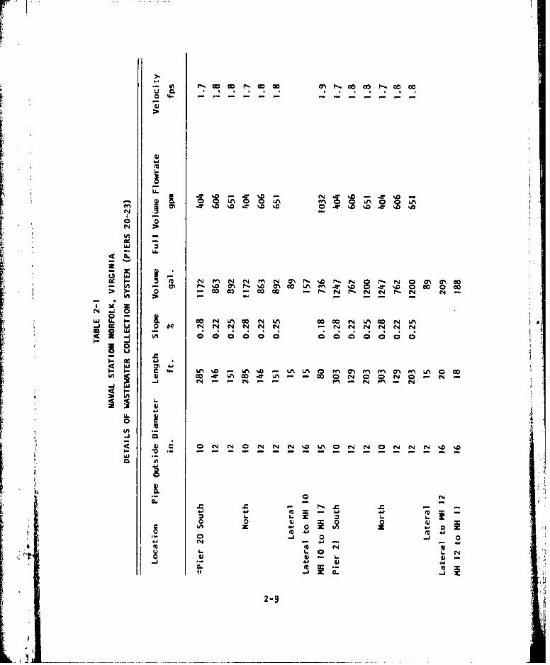
U, fG o r c c "c oK * c
-r0 T%
cm mI 0 UM m T %D T %-0-- -w w
0i 0i0 0
- U
4- LA %D 6M N ILN M MN C-"%~. ! N 0M M M
- - - - - - - - - - - --- - - - -
15 2
N -j 0(14N L 0 O N LA0 N L
-m
CL NN3NN
N - (N - N ~ -
2-
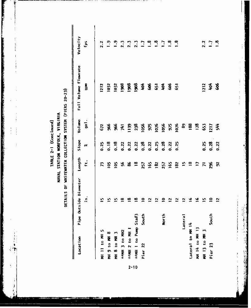
N 0~ CM M~g Nnr, 00 -0 0C r- c
o - N -N - - - - - - - -
L6
CL.
Nr N0 N0 .. t4 0- N NC1 A W LMc
v0-
N. 7 7 r
N
I U
C 4- 0 0 0A 00 L^% O. DC
i...
Lfl -
*n Ien - I
2"1 z XN -,N -N N
it 4 It
2-1

r4
Ln
r*ý r N N m - - N
(N NN NN rrN LLI
'.C -CU CM - -N -W w N- c
-i 4
0 M $
4jJ &a 00 00000
N ~2-11

capacity of the pump #1. Incorporated within the system is a sluice gate and
accompanying operator wheel to regulate the inflow of sewage to the wet well.
Also, a standby generator Is stationed so as to permit continuous operation
In the event of power failure. The wet well area Is vented by way of an 8
inch cast iron vent outletting to atmosphere. All pumps are mounted on
concrete pedestals and equipped with outlet check and gate valves, In addi-
tion, a sump pump Is situated below floor level and equipped to discharge
Into the adjacent wet well. Discharge from the three sewage pumps Is con-
veyed through a 10 Inch flow meter and then Into a 10 Inch force main and
subsequently to the municipal treatment facility, The actual pumping head
Is approximately 15 feet, An access for service and maintenance on the
pumps, piping and valves is by way of a stairway leading from the ground
level motor room to the pump room below. Figure 2-7 Is a cross section
schematic of the pump station,
2.4 Hose Cleaning and Storage Bullding
The structure is located east of the pier area and has provisions for
handling hose wash down and rack storage. The area Is outfitted with wash
racks and storage racks for collapsible sewage hose. For wash down purposes,
main supply water outlets are available. Personnel lockers, showers, laundry
facilities, and toilets are available along with office space.
i; 2.5 List of Pertinent Plan Drawings
The following table lists key drawings of the pier side collection
system:
TABLE 2-2 PERTINENT PLAN DRAWINGS
DESCRIPTION EFD DWG. NO. NAVFAC DWG. NO.
Location plan and list ofdrawings 110574 4010574
General plan 110575 4010575
Third Street, plan and profile 110577 4010577
B Avenue - Third Streetto Station 18+00 110578 4010578
2-12

DESCRIPTION EFD DWG. NO. NAVFAC DWG. NO.
Pier 20, plan and profile 110583 4010583
Pier 21, plan and profile 110584 4010584
Pier 22, plan and profile 110585 4010585
Pier 23, plan and profile 110586 4010586
Pier details 110589 4010589
Ship to shore connectiondetails 110591 4010591Shore gravity sewer andforce main details 110594 4010594
Pumping station #3, siteplan and elevations 110601 4010601
Pumping station #3, floorplans 110602 4010602Pumping stations #3, roofplan and sections 110603 4010603
Hose sanitation facility,general plan 110607 4010607
2i 12-1
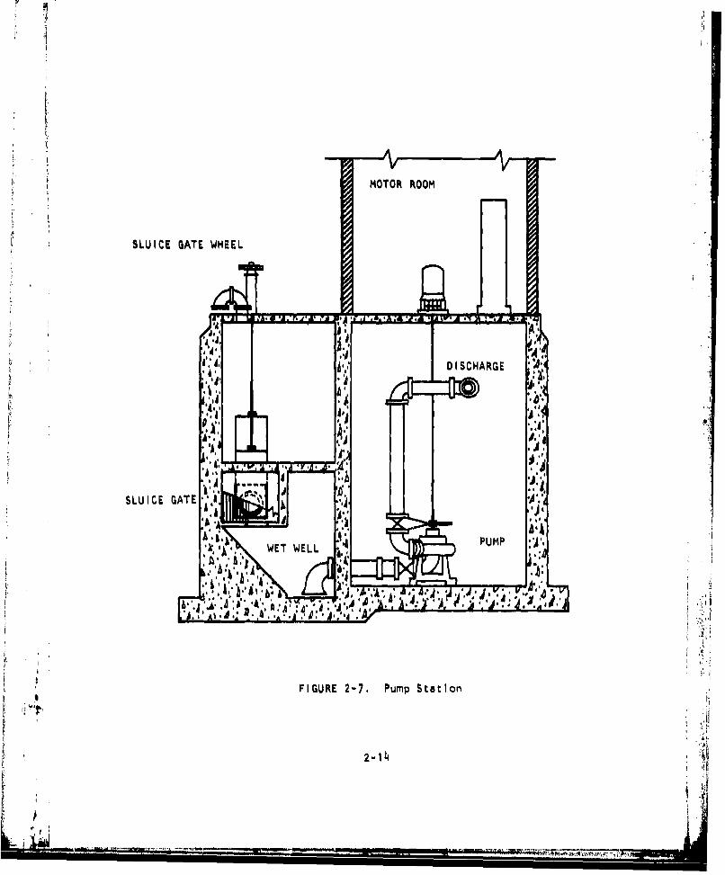
MOTOR ROOM
SLUICE GATE WHEEL
d'~4, h. ~DISCHARGE
A.,
SLU IC E GATE'A
1~. b V A
FIGURE 2-7. Pump Station
2- 1J4

rf
3. SHIP WASTEWATER CHARACTERISTICSrLFlushing water for shipboard sanitary systems Is provided by the solt
water firemain supply. As a result, the primary difference of ship verses
domestic sewage characteristics Is the chloride level. Generally, studies
have shown that ship generated wastewater settles well and can be treated
by normal biological treatment processes, Table 3-1 presents the character-
istics of ship sewage from NAVFAC Design Manual DM-5. Also Included are the
results of wastewater tests on USS Nimitz (CVN-68).
Most of the ships' CHT systems have garbage grinder discharges Into the
collection systems, These tend to Increase the suspended solids, BOD, grit,•:• primary sludge and scum.
The monitoring of volumes of ship generated waste have shown that In
actual practice the daily volume may be several times greater than the design
standard of 60 gallons per man per day. These high flows are generally the
result of a constant saltwater flushing source into the CHT system. Usually
the ship is unaware of this flushing.SPRUANCE class destroyers have Jered vacuum collection systems. These
systems collect and pump to shore a concentrated sewage of no more than 800
gallons per day.
3-1

I-
o.0 I N
zz
ccD
In
w?
L LA
3-2
L...

.. ..... .• .. .. . . , . ..
4. SEWER CAPACITIES
4.1 Sh.p Sewage Production
According to the berthing plan for fiscal year 1980 as detailed forpier operations at the Naval Station, piers 20 through 23 will accommodate
a total of 33 ships. The most common ships, In terms of wastewater pro-
duction, will be the destroyer type DDG. The total complement for ships'
personnel expected with the berthing arrangement Is 9,577 men,
Although NAVFAC design manual DM-5 calculates flow rates based on the
60 gpcd average, recent ship activations have shown waste generation rates
to be more than 144 gpcd. For the purposes of estimating the maximum flow
to the shore side collection system during the fiscal year 1980 planned
berthing arrangement, the following section considers a generation rate of
144 gpcd, Tables 4-1 and 4-2 summarize the expected ship volumes and the
flow rates derived from the expected berthing arrangement.
4.2 Expected Total Ship Loads
As shown in table 4-1, the average maximum 24 hour flow rate, at 144
gpcd for maximum berthing, Is 958 gpm. This Is derived from the number of
ships expected to berth at these piers and their respective complements. At
these highter rates, this would mean a total daily flow of 1,380,000 gallons
of sewage from this pier system. At 60 gpcd, the total daily flow from
these piers would be about 575,000 gallons.
Table 4-2 provides a comparison between the average 24 hour flow rate, .X,
the peak flow rate, and shore side system capacity. The peak flows shown "
are calculated based on 144 gpcd and are somewhat higher than the original
design. Yet, even with the higher design estimates, Individual pier sewers
have capacities that are fairly close to the peak flow estimates. Only for 4
the combined peak flows is the shore side capacity Inadequate. What must
be remembered about peak flow rate Is that Is occurs for a relatively short 414-1

I- -
LIA
4.'1
O-t~~C C-- 0 A
0 6M M W0m.-
a. Im
#AAm O
00
- N
4-' N N 4-2

TABLE 4-2
SUMMARY OF PLANNED BERTHING
ARRANGEMENT DISCHARGE TO SHORE SIDE
COLLECTION SYSTEM
Avg. 24 hr. Flow Peak Flow Shore SideLocation gpm. (DM-5) CapacityA
gpm. gpm.
Pier 20 153 998 1032
Pier 21 322 1668 1212
Pier 22 215 1125 1212
Pier 23 270 1460 1212
All Piers 958 4218 1908
*For each pier: flowrate of pipe section to main sewers.
All piers: flowrate MH #1 to Pump Station.
A
4-3

• ••• -• • =. . . ......... .... . . . .. . .. . F',
duration of 3 to 5 minutes for any single ship pumping. During this short
pumping cycle, about 400 gallons per ship Is discharged into the sewer. The
sewer piping must be filled up before the system exceeds full pipe capacities.
The difference between the peak flow and shore side capacity Is about 2,300
, gpm. At this rate It would take approximately 16 minutes of peak flow
pumping to fill up the piping system and pressurize all the sewer. PeakI flows will not occur for this length of time.
4-4
r1
I iI.

5. SEWER PROCEDURES-NORMAL
5.1 Connecting Ships
The NAVFAC Ship-to-Shore Hose Handling Manual, MO-340, provides detail-
ed tasks for ship to shore sewage connections for a variety of ships and cir-
cumstances. The following Information provides additional guidance for
making connections at the Norfolk Naval Station.
The first step In making a successful ship to shore sewer hookup Is
knowing the requirements of the ship for shore side supplied sewage transfer
hose and fittings. A log book with pages similar to Figure 5-1 recording
the requirements and pier use history for each ship should be developed and
maintained as more and more ships begin using pier sewers. This log provides
a ready reference to the hose handling crew to provide the proper length of
sewage transfer hose and fittings for each ship request.
The shore side handling crew requires at least two men. It Is the res-
ponsibility of the shore side crew to meet with the ship's CHT officer to
Insure that his men are available and understand how to mmke the ship connec-
tions. Generally, at least three men are required aboard ship for this task.
The ship's crew Is not expected to handle sewage equipment on the pier.
At the Norfolk Naval Station there are two hose reel trucks which reduce
the amount of manual handling of sewage hose for each connection. These
hose reel trucks are dispatched in a timely manner to permit the Immediate
hookup of sewage hose to ships arriving at berth, All necessary fittings
are Included aboard each hose reel truck. Knowledge of the power reel assem-
bly is essential to Insure that hose lengths do not become kinked or jammed
In the process of extending hose lengths.
The following procedures will aid In efficient ship to shore connections:
4. a. Sufficient hose lengths are loaded aboard the hose reel truck at the
5-1

r
SHIP LOG SHEET
SHIP:I DISCHARGE RISERS/SIDE:
HOSE SIZE:_________ ___EXPECTED GPO:______ . ......DIRECT HOSE FLUSHING AVAILABLE: YES NO--
CONNECT AISTN HOSE DISCONNECT TOTAL REAKDATE PER TH NO. LENGTH DATE PV NG_ REMARKS
0'
'I..-
I.
* I
II a
FIGUR 5-1 LogShee
FIGURE 5-I, L2 he

hose handling facility. In addition, necessary fittings are
Identified and placed on the storage area of the truck. The truck
Is dispatched to the berthing area and the pier risers to be used
are identified. Sufficient hose lengths are paid out from the
hose reel and connected to a heaving line for passing to the ship.
The female end should be plugged at this time and the cap Is recov-
ered from the ship before the shore hose handling crew departs.
b. The pier sewer risers are located under hinged covers In the pier
deck. The pier sewer is a continuous gravity system and does not
run full and Is, therefore, not pressurized. Connections at thet99 Naval Station are of the multiple collector design, including twoF: camlock connections at each riser assembly.
c. Because the pier riser fitting Is set below the pier deck level, It
Is necessary to connect a 900 adapter fitting to the pier riser.
This 4 Inch camlock adapter fitting rises approximately 15 Inches
above the deck surface to connect with the ship sewage transfer
hose and prevents kinking.
d. To minimize the chance of accidental sewage spill, the shore crew
must Insure that the hose connection to the pier sewer riser ie
completed prior to the ship deck riser connection. In most cases,the adapter riser should be turned so that the connection Is par-ailed to the length of the pier. By connecting the hose In this way
the chances of hose kinking are reduced.
e. The last task for the shore side hose handling crew is to arrange
the hose along the pier to minimize hose kinking, contact with steam
lines, and away from vehicular traffic. The hose should be examined
for leaks as the ships begin pumping and If gaskets or hose sections
then require replacement, procedures for hose flushing and draining
as described In the following sections should be followed before
making repairs.
f. Because the Naval Station has multiple collection riser assemblies,I care should be exercised when accessing the second camlock fitting
once the first fitting Is accepting sewage. The procedure to be
5-3
nm = -. ... .I . .. ~ lJ Ill I t I
followed should be to temporarily close the ship deck riser while
the connection to the second camlock fitting is made.
g. Vibration of camlock fittings during ship pumping can cause the
locking ears to come loose. A safety band tied through the cam-I lock rings will prevent this.
S5.2 Disconnecting Ships
Detailed procedures for disconnecting sewage transfer hose from ships
and other vessels Is described In NAVFAC MO-340, chapter 8,
a. The shore side hose handling crew should check with the shipboard
personnel to insure that disconnecting procedures are understood
and coordinated. At this time, plugs for the 4 inch camlock hose
should be provided to the shipboard crew. These will help prevent
spills as the hose Is lowered,
b. Ships have been Instructed to flush the sewage transfer hose with
saltwater from the firemaln connection Installed In their CHT
discharge piping. This flushing of the hose for 10 minutes Is all
that Is usually required to clean sewage transfer hose. The shore
crew should check with the ship to be sure that this procedure has
been accomplished. At this time some ships are unable to provide
direct saltwater flushing and, as such, the shore crews should be
aware if the hose has not been properly flushed.
c. After flushing, the ship disconnects from their deck riser and
drains the hose by allowing it to vent through their open fitting.
At this time the shore crew should raise the low spots of the hose
to allow it to drain into the sewer. Only after all draining Is
accomplished is the hose plug installed on the open hose.
d. The hose Is disconnected from the pier riser only after It has been
lowered to the pier. Hose caps and plugs should be removed before
the hose Is coiled and placed on the hose reel, This will allow
the hose to vent while being reeled onto the truck.
, e. The pier riser adapter Is removed when the sewage hose is
5-4

disconnected and the sewer riser plugged when not in use.
f. After returning to the hose handling and storage facility, the
shore side crew should Inspect all fittings and hoses for damage
and separate them for maintenance purposes. Properly flushed
sewage hose can be immediately used for other ship connections
without further cleaning or maintenance.
5.3 Small Craft
Pier sewers will accept sewage from small craft and Sewage SWOB barges.
At this time there has been little experience with procedures for these
craft. They will be developed and Included In NAVFAC MO-340.
5.4 Sewage Transfer Hose
There are several types of sewage transfer hose available for large
ships, submarines, and small craft. Large ships with CHT systems use
standard 4 inch camlock fittings on 4 Inch hoses. Submarines use a 2 1/2
sewage hose with camlocks fittings and small crafts use 1 1/2 Inch camlock
fitting which prevents its use In other utility services, The hose Is a
clearly marked "'SEWAGE''.
Sewage transfer hose comes In two designs. Originally, all facilities
were outfitted with the 4 inch collapsible hose 50 feet, 130 pounds, manu-
factured according to MILSPEC-H-20176. A rigid wall, wire reinforced
gravity transfer hose is also available for new procurements under MILSPEC-SH-20176D, Five years of continuous service life for all hoses should be
expected,
SThe collapsible hose Is suitable for all sewage transfer operations.
However, the operator will note that It kinks easily and can shut off the
flow from the ship. Additional care, then, must be taken to prevent hose
kinking, particularly with rise and fall of the tide. Additional 90-
degree elbows, temporary hose saddles, and tie-offs may be necessary. Ship
hose connections should be regularly Inspected by utility crews to Insure
that kinking has not occured.
As ships are pumping sewage, the collapsible hoses will pulse. This
pulsing can quickly cause chafing of the hose and severe damage without
5-5
-Ii

proper precautions. This is particularly severe where the hose passes over
concrete pier curbing.
5-6
-A

6. SEWER PROCUDURES-EMERGENCY
vi As the pier sewer systems become a regular part of the utility ser-
vices, these pier sewers must be kept operating with a minimum of service
disruption In the event of system failure. This section provides some
guidance as to some of the problems that may be encountered In repairing
the pier sewer system and some methods to restore pier sewer service as
quickly as possible with a minimum of disruption to shipboard operation.
6.1 Sewer Line Break
The pier sewer systems are Interconnected to a common sewer main and
pump station. This interdependence complicates the effect of a sewer line
break or a major leak throughout the entire system. Breaks have already
occurred on these piers. It should be noted that most of the pier sewer
piping Is submerged at high water, thus the greater cause of concern Is the
uncontrolled entry of seawater Into the pier sewer system to the pumping
station. The temporary Isolation of broken pier sewers at the NavalStation has been accomplished by Installing a ball-type rubber plug at the
manhole Intersecting to the shore side sewer system. This Isolation served
to be an effective means to continue operation of piers 20, 21, and 22.
Also located at the Naval Station is a sluice gate at the Inlet to the pump
station. This device will also serve to isolate the pump station from a
large Intrusion of seawater as a result of a main break on any of the pier
sewer lines, Figure 6-1 and 6-2 show examples of sewer plugs.
Pier sewer breaks may occur for the following reasons:
1. The under pier sewers are hung close to the pier fender piling and
can be damaged from docking Impacts.
2, Fender camels can become wedged under the pier sewer piping and
crack the piping as they rise with the Incoming tide.
3. Gradual saltwater corrosion can weaken sewer pipe flanges and
6-1

F IGURE 6-1. Air inflatable Rubber Plug
FIGURE 6-2. Mechanical Screw Expandable Plug
6-2

expansion joints.
4. Seasonal ground settling can cause buried sewer line cracks,
resulting in the infiltration of ground water. These cracks
will not usually cause massive seawater Intrusion but should
be Identified and repaired to limit unnecessary treatment
plant processing charges.
If a major break occurs in the pier system It will be necessary to
physically Isolate that pier sewer from the rest of the system. The pier
sewer line can be most effectively Isolated with the use of a sewer plug
as has been used on Pier #23 at the Naval Station.
L A stock of these emergency repair type materials Is available to alimited degree at the Naval Station. Additional materials should be pur-
chased for ready use In the event of such sewer pier failures.
It may be necessary to delay the use of the sewer plug until a suit-
able tide level occurs, The safety procedures for manhole entry are dis-
cussed In section 7 and should be strictly followed for emergency repairs,
The below sequences should be followed by the Public Works Center
utility division In dealing with a major break: -
1. Upon notification of a pier sewer break, the ship up line of the
break should be notified to secure sewage pumping. At the sametime, port operations should be notified to provide sewage SWOB
barges for the ship or alternative pier berths.
2. Notify the Hampton Roads Sanitation District (HRSD) of the possi-
bility of Increased saltwater content of the wastewater generated
from Naval Base. This will provide the opportunity to monitor
the wastewater and provide additional holding and mixing time.
3. Identify the appropriate manhole for sewer plug insertion. Pre-
pare the necessary equipment for manhole entry and notify the W.
safety department to provide a gas free certification of the man-
hole. e
4. Determine the appropriate tide level and time from port operations
when the sewer pipe may be accessible from the manhole.
5. Gather all necessary equipment for repairs and safety. Proceed to At
the selected manhole. 6-3
6-3I

6. Install sewer plug.
After Initial emergency plugging It may be possible to take some
corrective action to provide a temporary fix for the broken pier piping.
Small leaks and breaks may be repaired by the use of a mechanical pipe
patch which is secured around the pipe diameter and tightened by any
openended wrench.
The repair of broken pier sewer piping should be treated as an emergency
and contracted accordingly. Sources of repair pipe and contractors withsuitable equipment should be Identified beforehand.
Sections of pier piping may be usable if the Isolation plug is In-
stalled at the side of the pipe break. This will allow at least a portion
of the pipe sewer to be used and additional sewage transfer hose can be pro-
vided to the ship so that it can pump to the nearest available sewer riser.
Waterfront operations should be kept Informed of pier sewer repair
conditions so that they may provide alternative berthing arrangements. Ships
equipped with sewage transfer systems will be required to berth at piers with
collection capability.
6,2 Industrial Waste Intrusion
Pier sewer systems have been used as a convenient but Improper way to
dispose of a variety of Industrial waste from ships. These may Include oil
wastes, paint and paint thinners, boiler cleaning compounds, and a variety
of shipboard hazardous materials. These wastes are usually first noticed in
the pump station wet well and can be traced to their source via the pier
sewer line, If Intrusion Is noted, action to remove the material must be
taken. Also, HRSD should be Immediately notified so that they can monitor
their Inffluent and take appropriate action to protect their treatment
processes. At the Naval Station, facilities are available to provide pump-
out of the wet well, If evidence of hazardous material exists In the sewers
It must be flushed by a fire hose while collecting the material at the
sanitary wet well.
Industrial waste material and flammable liquids enter the pier sewer
piping only through the pier riser connections or directly into the manholes.
Material spills Into open areas that reach storm drains will not reach the
pier sewer system. In most cases these drains discharge directly Into
6-4
SIvvs. I=i•'

the harbor. In the event of flammable material entering the sewer system,
the Naval Station Fire Department should be notified and requested to Inject
aqueous film-forming foam (AFFF) Into the pier sewer piping, manholes, or
sanitary wet wells as necessary. AFFF Is a toxic material and Its use in
sewers should be limited.
6.3 Electric Power Failure
The pump station is equipped with an emergency generator that Is auto-
matically activated as a result of base power failures. This emergency
power will be provided sufficient pump power for the requirements of the
shore side sewage collection system.
It Is the usual practice of ships berthed at the Naval Station to use
shore supplied power, In the event of shore side power failures, the ships
will change to onboard emergency generators to provide partial ship power,
it is the usual practice, however, that sufficient power will not be made
available to its transfer system (CHT), therefore ships will not usually be
pumping to the pier sewer system during base power failures.
If the pump station emergency power falls, ships connected to the
system should be requested to begin holding or divert their systems until
the power failure has been corrected, Failuros of long duration will
require sewage SWOB barges to be used to hold the ships' sewage.
6,4 Sewage Spill Procedures
Sewage spills occurring on open areas of piers most frequently occur
from sewage hose failure, Improper hose connection procedures, or vehicle
damage to the pier riser fittings. The first concern In responding to a
sewage spill Is to keep personnel away from the area. Stop the source of
the spill and flush down the area as quickly as possible. More detailedprocedures are discussed in the following health and safety section.
6.5 Emergency Notifications
Any of the above emergency situations requires the notification of
the following:
6-5

1. Port Operations Duty Office -2301
2. PWC -4431 day-3477 night
3. Safety Department -7351
4. Hampton Roads Sanitat.ion DistrictArmy Plant 423-7568
6-6t I
6-6
i. (

7. HEALTH AND SAFETY
The operation and maintenance of ship to shore transfer systems Is
no more hazardous than other waterfront operations. The safety and health
precautions for this work require mostly a common sense approach, Histori-
cally, workers In the maintenance of sewer systems and the operations of
treatment plants have enjoyed an excellent health and safety record, Work-
eri with the ship to shore sewage transfer system should be aware of the
following health and safety precautions,
7.1 Health Precautions
SClothing. The following list of clothing Is suggested for most rou-
tine operation and maintenance procedures. Clothing should be washed
frequently and a spare set of work clothes or coveralls available in
a locker to provide a fresh change of clothing If necessary. No
special segregation of this clothing Is necessary for washing. It can
be washed with regular home laundry,
Hardhat. An approved hardhat Is required for all work pier side
and this safety procedure should be carried over to the main-
tnance workers of the shore collection system,
Work Clothes. Regular work clothes or coveralls are all that is
required for exterior clothing and working with sewage transfer
hose. Coveralls and waterproof aprons are recommended when
cleaning hoses or working with wet equipment.
Work Shoes. Steel-toed work shoes must be worn at all times
"when handling sewage transfer hose and fittings as well as
performing maintenance tasks. Steel-toed rubber boots should be
worn while making hose disconnects or when In wet sewage environ-
ments.
Washing Up. This Is the most Important category of health precaution
to prevent unsanitary conditions, Workers must remember to wash hands
7-I

and face after handling sewage equipment prior to eating, smoking,
or drinking. This must become a regular habit of all sewage system
workers. Hand washing and shower facilities are available In the hose
cleaning and storage building.
Health Records. The base dispensary should be requested to mark the
health records of personnel working with sewage transfer equipment
with the following: "Occasional Contact With Raw Sewage".
.Uhot Records. BUMED has recommended that the normal series of Inno-
culatlons be maintained for all personnel working with sewage equip-
ment. These are tetnus, typhoid, and polio. Innoculations, If kept
up to date, should provide a sufficient level of protection to the
workers. Workers should be particularly careful with open cuts andmust be sure to prevent Infection by adequately cleaning any wounds.
The dispensary should be visited for treatment any Infections, sewage
contact with eyes, or any abnormal health condition that may occur,potpble Wa-ter Connections. Personnel working with sewage transfer
equipment must not subsequently make potable water connections, If
It Is necessary to connect to a water hydrant to hose down an area
of a sewage spill, a different worker should be called to make the
connection and handle the fresh water hose.
7.2 Safety Precautions
Pier Ooerations. The shore crew for sewage transfer hose connections
and disconnection procedures requlreb at least twl men. While the hose
at the Naval Station Is supplied on a hose reel truck, two men are stlil
advisable when handling the actual connection. Hardhats are necessary
while on the piers, particularly when the hose Is raised and lowered to
the ship.
Manhole and Wet Well Entry. The following equipment Is necessary for
the safe entry Into a sewer manhole or sanitary wet well.
1. Safety Barricade
! v, '2. Safety Harness and Life Lines
3. Ladder
7-2

4. Explosion Proof Lighting
5. Manhole Lifter
6. Portable Ventilating Blower
The Instructions for entering and working In confined spaces such as
sewer manholes are contained in Public Works Center Safety Instruction
5100.26. This instruction requires a gas-free permit to be Issued by theSafety Department prior to entering a manhole or sanitary wet well. It
should be remembered that the ladder rungs Installed In manholes are par-
ticularly subject to corrosion because of the corrosive atmosphere of the
saltwater sewage In these systems. These ladder rungs should be inspected
for deterioration and tested with a hammer. If necessary, the manhole
should be entered by a supplementai portable ladder If there Is any ques-
tion.
The presence of explosive and/or toxic gasses or an oxygen deficient
atmosphere should be of constant concern to sewer maintenance workers.
These gasses cannot be detected by smell and must be regularly tested by
a proper sampling meter. If there is any doubt as to the condition of theatmosphere within a confined manhole, forced ventilation with a blower
should be provided.
7.3 Sewage Spill Cleanup
Sewage spills are most likely to occur around the pier sewer connection
riser and Immediate pier deck area. These are usually the result of Insuffl-
cient hose drainage prior to disconnection, leaking hose gaskots, hose rup-
ture, or the action of a ship inadvertently pumping through a disconnected
sewage hose. The basic procedure Is to flush the area clean, The followingprocedure should be used and adapted for various sizes of sewage spills.
-- Secure source of spill.
-- Close off area to unnecessary traffic and personnel.
"--Flush area with fire hose from hydrant or water truck (a separatenon-contaminated man should be called in to make hydrant connectionand handle the hose) - saltwater from a ship hose Is preferred.
7-3
7.N

-- Use disinfectant or detergent to cut odor or grease If needed. (Use
a dry phenolic compound or any stock detergent).
-- Flush area again.
-- Open area to regular activity.
The disinfectant recommended In MO-340 is germicidal, fungicidal con-
centrate (Phenol ic dry type) stock 6040-00-753-4797. Chloilne (HTH) should
not be used around piers or other areas where It may come In contact with
grease or oil.
.."
I
7-4
2 ,' l•

B. MAINTENANCE
The maintenance of pier sewer systems will become part of the regular
maintenance program for the sewage system at the Naval Station, The design
and InstAllation of the pier sewer system is similar to that of dome ,,
sewers. However, there are some differences and precautions to be noted
in the maintenance of this system. The following sections highlight parti-cular problems with pier sewer maintenance.
8.1 Regular Maintenance
The Increased chloride level of ship generated waste will aggravate
the effects of corrosion on the pier sewer system. More rapid deteriorationS will occur In the cast Iron pipe sections, mechanical joints, and manhole
ladders.
Regular daily InsDections of the pier sewer system are Important to
insure continued trouble-free operation. The following daily inspections
should be made:
a. Sewage transfer hoses from ships pumping Into the piers' sewers
should be Inspected for tight camlock connections, leaks around
gaskets and fittings, kinks In the collapsible hose, excessive
weight from catenaty bends, and contact with hot steam lines and
hose chafing.
b. While 3hips are pumping Into pier sewers, whenever possible, visual
Inspection of the exposed under pier collection lines should be
made to observe for any damage or leakage. This Inspection Ic best
accomplished at low tide when all under pier piping will be exposed.
c. The pumping station wet well should be examined for evidence of
1 4: oil or excessive grease buildup. If excessive oil or chemicals
are present, pier sewer manholes should be examined to Identify
_ _

F'. . rnm't • .. ., - -.. . . .... .. . . .. . .... . . . . .. .. . ... • % .''a•. ....~ - .. - / -' ..- o-
the source and isolate the same.
Less frequent inspections should be made at least weekly or as theyt occur In the following areas:
a. When no ships are using the pier system, a manhole should be
Inspected to determine the rate of any Infiltration, This would
be best accomplished during high tide at maximum submergence of
the pier piping.
b. All underpler piping should be Inspected for damage and evidenceI of leaking.
.... 8.2 Regular Sower Maintenance
The majority of the pier system piping at the Norfolk Naval Station.. 'has full pipe flow velocities less than the design standard established in
NAVFAC DM-5 of 2.5 feet per second. As a result, these portions of the
sewer system may quickly accumulate solids as a result of buildup due to the
low flow rates of sewaga, As the i'requency of pier sewer use Increases,
at least quarterly inspectlinis.of these sections of the sewer system will
be necessary to determine the rate of sludge buildup. inspections of man-
holes should Include observation forexces-a.ive oil, the evidence of sewer
gas, Infiltration, and pipe bluckage, As solids buildup occurs line
flushing and cleaning will be required. The Naval-'ttsý,ion piers are
equipped with cleanout access points adjacent to each shilplu shore connec-
tion. Flushing and cleaning operations should be conducted from*3e most
upstream portion of the system and stepped down to the pump station.
Extreme care should be taken during excessive cold weather periods
which may cause line blockage from ice formation, It Is the nature of CHT
operation that the pier sewer is regularly doused with about 300 gallons of
sewage from one ship pump firing. This dousing will occur Infrequently,
'4 about once an hour, particularly during the coldest hours in the early
m.morning, Since this flow Is not constant and Is of an Intermittent
nature loading may cause rapid ice buildup In the sewer lines. Until suffi-
cient experience with cold weather operations in gained, extreme care
should be taken to avoid the formation of Ice. The pier piping should be
Inspected and maintained as necessary, Camlock gaskets found In the pier
8-2

risers and hose require replacement about yearly to maintain a tight and
leak-free connection.
8.3 Hose Maintenance
Regular maintenance procedures for sewer transfer hose are outlined in
MO-34O. Normal flushing of sewage hose with ship saltwater flushing connec-
Stions will provide sufficient cleaning of the seage hose prior to dis-
connection. The most Important maintenance function to be performed on the
hose is routine inspection prior to hose storage. Evidence of leaks or
excessive abrasion should Indicate that Individual hoses should be removed
from service and bad sections removed by shortening the hose lsngth, if
possible. For hose In continuous service MO-340 recommends a hydrostatic
pressure test to 100 psi at least every ninety days.
Additional hose cleaning Is to be performed only when ship hose
flushing Is inadequate. The pier utility crews should encourage each ship
to properly flush the hose. Several ships do not have direct flushing
capability yet. These ships should be Identified so that additional
cleaning of those hoses will be performed.
8-3
SHIP WASTEWATER COLLECTION SYSTEM
STANDARD OPERATING PROCEDURES
FOR
DRYDOCKS 3, 4, and 8
NORFOLK NAVAL SHIPYARD
PORTSMOUTH, VIRGINIA
.4j
*1•LA__•

TABLE OF CONTENTS
Norfolk Naval ShipyardPortsmouth, Virginia
LIST OF FIGURES . . .. . ..... .. . . . . . . . .. .. . . . iiLIST OF TABLES . . . . . . . . . .. . . . . . . . . . . . III1. INTRODUCTION..... ..... . . . . . . . ........ 1-1
1.1 Background . . . . . ... ... ... . . . .. . . 1-1
2. FACILITIES AND EQUIPMENT DESCRIPTION ....... .. 2-12.1 General . . . . . . . . . . . . .. 2-1
2.2 Drydock Sewers......... . . ......... . . . 2-32.3 Hose Cleaning and Storage Building ...... .. 2-112.4 List of Pertinent Plan Drawings . ..... . . . . . . 2-11
3. SHIP WASTEWATER CHARACTERISTICS . ....... ....... ......... 3-1
4. SEWER CAPACITIES . . . . . . . . . . . . ......... 4-14.1 Ship Sewage Production . . . . . ........ . . 4-14.2 Expected Total Ship Loads... ... ....... ....... . . 4-1
5, SEWER PROCEDURES - NORMAL . . . . . ........ . . . 5-15.1 Connecting Ships. . . . . . . . . . . .. . ...... 5-15.2 Disconnecting Ships ....... ....... ..... ..... ... 5-25.3 Sewage Transfer Hose . . . . . . . . . . ....... 5-2
6, SEWER PROCEDURES - EMERGENCY ,............. . ... 6-16.1 Sewer Line Break . ,. . . . . . . . .. . 6-16.2 Industrial Waste Intrusion ...... ....... ....... 6-16.3 Sewage Spill Procedures ..... ... ... . ...... .6-26.4 Emergency Notifications ....... ..... ........... ... 6-2
7, HEALTH AND SAFETY ............... .......... .. ... 7-17,1 Health Precautions .............. . ... 7-17.2 Safety Precautions. ....... ..... ... ......... ... 7-27.3 Sewage Spill Cleanup . . . . ................ 7-3
8. MAINTENANCE .............. ..... .... 8-.8.1 Regular Maintenance ....... ....... ........... ... 8-18.2 Regular Sewer Maintenance ....... ....... .......... 8-28.3 Hose Maintenance ......... .......... ....... ... 8-3
tp

LIST OF FIGURES
FIGURE PAGE
2-1 Sewer System Schematic . . ............ 2-2
2-2 Drydock 3 and 4 Layout............ . . . . 2-6
2-3 Drydock 8 Layout . . . .. . . . ...... 2-72-4 Riser Extensions Drydock 3........ ... ..... . . . 2-8
2-5 Drydock 8 Riser Detail...... ......... ... . . . . . 2-9
2-6 Drydock B Flu3hing System 2-10
5-1 4 Inch Sewage Hose ...... ....... ..... .... 5-4
5-2 Submarine Hose Adapter...... ....... ..... . . . . . 5-4
TABLE PAGE
2-1 Details of Wastewater Collection System . . . . . . 2-4
2-2 Pertinent Plan Drawings . . . . . . . . . . . . . . . 2-12
3-1 Ship Wastewater Characteristics . . . . . . . . . . . . 3-24-1 Planned Berthing Drydock5 3, 4, and 8 . .. .. .... 4-2 !4-2 Summary of Planned Berthing Discharge to System . . . . 4-3
Iii

1, INTRODUCTION
This manual contains standardized operating procedures for use with the
sewage collection systems Installed on drydocks 3, 4, and 8 at Norfolk Naval
Shipyard, Portsmouth, Virginia. These sewers collect sewage from ships while
In the drydocks. This manual also contains useful reference information as
to capacities and designed characteristics of these sewers.
The sewers Installed on the piers at the shipyard are similar In con-
struction and operating procedures as those described in the procedure
manuals for the Naval Amphibious Base and Norfolk Naval Station.
In using this manual, it is hoped that those working with the systems
will better understand their operating peculiarities so that better utility
service can be provided to ships while in drydock.
1.1 Background
The Norfolk Naval Shipyard, Portsmouth drydock alterations for the
sewer system was installed by a 1974 MILCON project. These sewers are de-
signed to collect shipboard generated wastewater pumped ashore by Collection
Holding and Transfer (CHT) Systems and other Marine Sanitation Devices (MSD),
These systems are the result of the Federal Water Quality Act of 1972 and
DOD Directive 6050A4. The Navy has complied with this directive through
OPNAV instruction 6240.3E and the Installation of shipboard systems and
shore side sewers.
The sewers are designed to collect wastewater primary from CHT systems,
as these will be installed on the majority of the vessels In the drydock,
Other systems on larger vessels Include Jered vaccumn collection systems
which discharge a more concentrated lower volume effluent. All Navy vessels
will have Installed systems by 1981, Properly equipped vessels are required J
to operate their systems prior to that date.
The operation of CHT systems with pler sewers has been well documented
from field tests and extensive operating experience at other Navy port
1-1 =
"J
............................................

complexes. The procedures outlined In this manual are well proven from
this field experience. General operating guidance for ship to shore sewage
transfer hose connections, cleaning, and sanitation are documented in
NAVFAC manual MO-340. Additional Information and support Is available
from NAVFACLANTDIV Environmental Division and public works departments of
other Navy activities.
This manual expands on the recommendations In MO-340 as they apply
to the Norfolk Naval Shipyard and is organized Into the following chapters:
2. FACILITIES AND EQUIPMENT DESCRIPTION. Discusses the general purpose
of the system and the details of the drydock sewer system.
3, SHIP WASTEWATER CHARACTERISTICS. Presents Information on the con-
tents of ship generated wastewater expected to be discharged at the
shipyard.
4. SEWER CAPACITIES, Presents data on the expected loading of the
sewers and the calculated capacity of the systems for a maximumplanned docking arrangement,
5. SEWER PROCEDURES- NORMAL. Discusses additional procedures to be
followed when connecting or disconnecting ships to the sewers.
6. SEWER PROCEDURES- EMERGENCY, Presents the emergency procedures to
be followed for emergency conditions and repairs,
7, HEALTH AND SAFETY. Provides personal health and safety precautions
for working with sewer transfer equipment.
B. MAINTENANCE. Recommends daily and regular maintenance for the
sewer system.
1 2II
1-2

2. FACILITIES AND EQUIPMENT DESCRIPTION
2.1 General
The collection and transportation of ship generated wastewater to the
shoreside treatment facility Involves several Interrelated systems and
activities. These are:
SYSTEM ACTIVITY
a. Shipboard sewage Collection, Holding
and Transfer (CHT) system or MSD. Ship
b. Ship to shore sewage transfer hose
and fittings, and ship connections. Shop 99
c. Pier sewer Installations, PWD
d. Sewage pumping station. PWD
e. Sewage Treatment City ofPlant, Portsmouth
Figure 2-1 Is schematic of a ship to shore wastewater transfer system.
Ship wastewater Is collected and held by the ships' CHT system and pumped
to shore through the sewage transfer hose to the pier sewer. The waste-
water flows by gravity from the piers or drydock sewers to other larger
buried sewer lines. These larger sewers at the shipyard join other sewers
from shops and other sanitary drains on the Naval Shipyard. These flow
to a common pumping station which periodically pumps the collected
sewage through a pressurized force main to the City of Portsmouth Sewage
Treatment Plant. The treated water Is then discharged from the plant at
the plant's outfall pipe.
2-1
__ __ -

Lo z
Mai
~1 31
00
LU6
LALU
LU&
A.
L6
2-2

2.2 Drydock Sewers
The sewer system related to the drydocks 3, 4, and 8 on the Shipyard
consist of 5,137 lineal feet of 6, 8, 10, 12, and 15 Inch diameter ductal
iron and viterous clay pipe. The total full volume of the entire drydock
system including the collectors and main sewers to the existing collection
lines is approximately 21,332 gallons, with Individual pipe full flow rates
ranging from 1,257 to 305 gallons per minute. The flow rates of the larger
15 Inch piping are about 1100 gallons per minute at velocities about 2.0
feet per second. Table 2-1 gives the details of pipe size, capacity, and
velocity. The minimum velocities of drydock 3 piping Is 1.9 feet per se-
cond. The collection piping of drydock 8 Is a force main with intermltent
salt water purge which Is automatically controlled.
It should be noted from this table that many of the section velocities
are below the DM-5 minimum velocity requirements of 2.5 feet per second.
This velocity requirement was intended to minimize the solids deposition
which cause sewer sludge buildup and possible line blockage.
The collection piping along drydock 3 and 4 Is equipped with vents
to facilitate gravity draining and cleanouts to provide access for flushing
and cleaning equipment if necessary.
Connection points are Installed along the piping of each drydock. Ship
to sewer connections are made with standard 4 Inch camlock fittings. The
camlock fitting Is exclusive to sewage transfer hose on shipboard Installa-
tions to lessen the possibility of a utility cross connection. As originally
installed, many of these camlock fittings on the sewers were inaccessable
for normal utility connection, These sewer risers are being channed by
the addition of new piping or turning piping elbows. Figures 2-2 1hrough
2-6 show details of the sewer layout Including those of the connection
fittings and the riser piping changes,
The drydock sewers and adjacent pier sewers Join to common sanitary
sewer pipes that collect from all Industrial buildings and adjacent domes-
tic sanitary drains on the Norfolk Naval Shipyard. These flow together
to the Green Street Gate pumping station through a continuous gravity
drain. From the Green Street pumping station, a force main discharges
to the City of Portsmouth municipal system.
The pumping station provides the only wet well for temporary holding
2-3
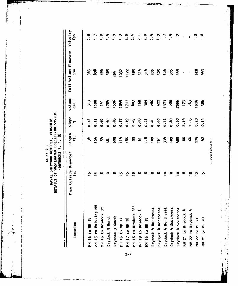
m M.
i'a
S"00.? " " -M C4
Z LA
'a. - - -o C ;. C; a NN -; -
vp CG -
At '. N 1 4 00%00C4*
0 C
d41
- 000000~~00 00 0 O I O
~ ..
1.0 Lr0 @0. .0%~~~4 U I~-2-

6N
ChC
LA c U km
-aw
O Lt% ' m -0r.
-4. J IN 61
NU6) u ~ o
E E z
LL L6 LL U
JD 00 0
4-~'J ~ O ~O k . 4
hO L~N r~.CO Ir~~~ 4
04-10'C
4), u-
CA LA 0 . IAn4
4JJ .v 4-1 L.jm AI oo4
0j 0 N Tx4 *- -W
Z ~ ~ J .9 ) I .4-. I ~ L
C14 V in . 0
2-5

LL
1 1 Id)
C%
uI§
z I X:c
2-6t
LlN

L.1
UUN
w 0llu-J
LIU
cc
0
LI.
2-7-

'I.'61
.14hU., *.*** q ¾
.r. .. *~.. . .. . . . . . . . . . . . . .
F ~, .*,, l~
* , **. * * *fl. 4* be
00
I-
6J6
IAA
2-8.
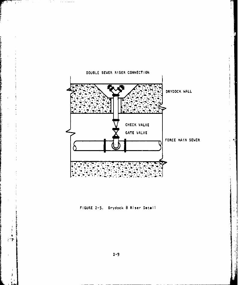
DOUBLE SEWER RISER CONNECTION
•.-!.._ ';, DRYDOCK WALL
,***b , ** ***, , - ,h **
CHECK VALVE
GATE VALVE
~A-3 FORCE MAIN SEWER
FIGURE 2-5. Drydock 8 Riser Detail
* ~2-9 5
L,. .. ,.:,:.

SALTWATER MAIN
FIGURE 2-6. Drydock 8 Flushing System
2-10
...... ,,"
I. i ' ~ i i. 'l,~l m ,O'4 p l J l,

of collected sewage waste. Also, at the pumping station is the only
sewage meter to measure combined ship and other shoreside flows.
2.3 Hose Cleaning and Storage Building
A steel building Is located near Gate 29 near Building 260 to provide
additional hose cleaning, maintenance, and storage. The building is out-
fitted with wash racks for cleaning and hydrostatic testing of sewage hose,
lockers, and office facilities for shop 99 personnel, Additional Improve-
ments to this building and area are being planned.
2.4 List of Pertinent Plan Drawings
Table 2-2 provides a list of reference plan drawings of the drydock
system,
[1It
2-11
L

TABLE 2-2
F PERTINENT PLAN DRAWINGS
EFD DWG. NAVFAC DWG.DESCRIPTION NUMBER NUMBER
Location map and list of drawings 113245 4013245
Site Plan - Drydock 3 113253 4013253
Site Plan - Drydock 4 113254 4013254
Sewer Profiles - Drydock 4 113255 4013255
Profile & Section - Drydock 4 113256 4013256
Profile & Section - Drydock 4 113257 4013257
Site Plan - Drydock 8 113258 4013258
Standard Details 113259 4013259
Plan & Details - Pier C 113261 4013261
Details -Pier C 113262 4013262
Profile& Elevation - Drydock 3 113263 4013263
Profile & Elevation - Drydock 4 113264 4013264
Details - Drydock 3 113265 4013265
Piping Plan - Drydock 4 113266 4013266
Profile & Elevation - Drydock 4 113267 4013276
Profile & Elevation - Drydock 4 113268 4013268
Details - Drydock 4 113269 4013269
Details - Drydock 4 113260 4013270
Details - Drydock 4 113271 4013271
Piping Plan - Drydock 8 113272 4013272
Piping Plan - Drydock 8 113273 4013273
Details - Drydock 8 113274 4013274
Details - Drydock 8 113275 4013275
2-12

r
3. SHIP WASTEWATER CHARACTERISTICS
The characteristics of shipboard generated sewage are somewhat dif-
ferent than those of regular domestic sewage. Since the majority of flush-
Ing water for shipboard systems Is salt water, the primary difference of
this sewage is the significantly Increased chloride level. In general, ex-
tensive studies have shown that ship generated wastewater settles well and
can be treated by normal biological treatment processes without adverse
effects to these systems. The main problem in treating high chloride level
sewage Is to avoid sudden shock loading of the treatment plant biological
systems. The sewage system at Norfolk Naval Shipyard provides an ideal
system of diluting the ships' sewage with normal fresh water sewage from
domestic sources. This dilution greatly lowers the chloride levels prior
to sewage arrival at the Portsmouth Sewage Treatment Plant. Table 3-1
gives the characteristics of ship sewage from NAVFAC Oesign Manual DM-5.
Also for comparison are the results of analysis of wastewater from the
U,S.S. Nimitz (CVN-68).
Most of the ship CHT systems have garbage grinders which discharge
directly Into the sanitary collection systems. These will Increase sus-
pended solids, BOD, grit, and grease In the ship sewage.
Field monitoring of waste water volumes generated from ships have
shown that In actual practice the daily volumes are several times greater
than the DM-5 design standard of 60 gallons per man per day (gpcd), Thesehigher daily rates (144 gpcd) are generally the results of constant saltwater flushing into the CHT system. The characteristics of ship wastewater
andvolumes received will vary according to the number of men aboard while
ships are in drydock. Limited flow should be expected when ships crews
are not I1ving aboard,
3-1
im11aL

r
Cm I co I I I (1
u
a--
0 VI IA"IA
0 w 0
A.P 0
0 10 LJ 4A.u
to4.')~j 0
00 0
3-2
j i

4. SEWER CAPACITIESii,
4.1 Shlp Sewage Production
sh For the calculation of ship sewage load, it will be assumed that, as•; '•shown In table 4-1, the drydocks contain 2 large cruisers and 1 large carrier.
This arrangement gives us a total complement of 6,914 men. The calculations
also will assume that the entire complement remains aboard while In drydock.
The design calculations used for maximum 24 hour flow rates and peak flow
rates are from NAVFAC Design Manual DM-5, The design manual uses a daily
per capita average of 60 gpcd, However, field testing has shown the average
closer to 144 gpcd. From the calculations, it can be seen that the larger
number significantly effects the maximum and peak flow rates.
These three ships, with a total complement of 6,914 men, produce an
average 24 hour flow rate of 692 gallons per minute at 144 gallons per capita
day. The average 24 hour flow at 60 gpcd is only 288 gpm.
4.2 Expected Total Ship Loads
The sewer loading flow rates based on the docking situation describedabove are summarized In table 4-2. This table shows a comparison betweenthe design standards and the field measured sewage generation rates. The
maximum 24 hour flow rates calculated according to DM-5 are a function only
of ships complement, and the per capita generated volumes. Although the wa-
ter use habits of a ship In drydock may be significantly altered from normal
pierside volumes, It should be expected that the maximum 24 hour flow rate
will be greAter then the design standard.
The peak flow rate is a function of the maximum pump discharge rate and
the maximum 24 hour flow rate for the multiple dockings of ships. For single
ships, according to DM-5, peak flow rates are a function of the design dls-
charge pump flow rate. What must be remembered about peak flow rate is that
It occurs for a relatively short duration of 3 to 5 minutes. During this short 4
4-1

0 0.
~l ~ I
L,.
- - 0 i
v 0o
C -,A Coh
z...--
0 Lo- U -
(A
0 00
4~-2

U. I
cc 0
Ina
UA.
CN
"I mG
Li.

pumping cycle of about 2,500 gallons, the sewer piping must be filled up
before the system exceeds full pipe capacities. The table shows that shore-
side sewers are capable of handling the maximum 2 4 hour flow rates but may
become pressurized during extreme peak flows for short durations.
r-
4-4

* 5. SEWER PROCEDURES -NORMAL
Note: Standard connection and disconnection procedures are presently
being developed for a PROCESS INSTRUCTION. Shop 99 has the primary respon-
sibility for ship to sewer connection and disconnection. This shop's re-
sponsibility Includes not only the shore side utility hookup but also ship
side connection as the Shipyard takes full responsibility for all utility
connections. The following discussion highlights some areas that should be
Included In the final Instruction.
5.1 Connecting Ships
a. An air blow down and salt water flushing fitting Is Installed for all
k ~ship to shore connections. The fitting is 4~ Inch X li X 14 Inch.The additional connections are for air and salt water flushing con-
nections. With this fitting, all flushing and draining operations
can be handled from the deck. Additional fitting% are necessary to
raise the deck riser discharge point above the passageway to the
outboard rail. All these fittings are provided by shop 99.
b. Sewage transfer hose should be properly tied off and supported at
each end to prevent accessive weight on thm hose fitting and to
prevent kinking.
c. Additional 90 degree elbows or 180 degree bends may be necessary to
prevent kinking as the hose Is connected to the sewer riser,
d. The pier sewer risers are not valved but have 4~ Inch plugs on dry-
docks 3 and J4. These sewers are continuous gravity systems and
shouid not be pressurized, However, caution should be taken whiie
removing these plugs.
e. To minimize the chance of an accidental sewage spIll, be sure that
the hose connection to the pier sewer Is completed prior to the ship
*1 - ... , . . . .

•r - r
•r r
deck riser connection. Thik will prevent any accidental pumping
by the ship through an unconnected hose.
f. The sewer on drydock 8 Is a pressurized line. Although the sewer
riser Is protected by a check valve and gate valve, care should be
taken when removing the plugs or disconnecting hoses as there may
be some leak-by of the check valve. Also, the multiple connector
of the riser may have two hoses connected to the same fitting. In
this case, be sure both hoses have been disconnected or the ship
deck riser closed before disconnecting from the pier riser,
g. All connections must be tagged to prevent unauthorized removal, In
addition, the camlock locking ears should be banded closed to pre-
vent them working loose.
5.2 Disconnecting Ships
Detailed procedures for disconnecting sewagA transfer hose from ships
and other vessels Is described In NAVFAC MO-340, Chapter 8.
a. The flushing of the sewage transfrr hose prior to the disconnection
Is all that is required to provide adequate hose cleaning. After
the hose has been flushed and drained, the hose is ready for use
after appropriate hydrostatic testing, The hydrostatic test lfmrts
for this hose shoulo not exceed 100 psi. Experience has shown thata 10 minute salt water flush from the deck riser Installed fittingand a three to five minute air blow down will usually do the Job
of cleaning. A second flushing and air blow down will locuen any
solids trapped In kinked sections of the hose.
b. The hose should be disconnected from the ship riser prior to discon-
necting at the sewer riser to prevent any accidental pumping through
an unconnected hose.
5.3 Sewage Transfer Hose
S There are several types of sewage transfer hoses available for large
ships, submarines, and small craft. Ships with CHT systems are standard 4
5-2
ib
r -

Inch camlock fittings on 4 Inch hoses. Submarines use a 2j inch sewage
hose with camlock fittings 3nd small craft use I1 Inch camlock fittings and
hose, All sewage transfer hose has the camlock fitting which prevents its
use In other utility services. The hose Is marked "SEWAGE".
Sewage transfer hose comes In two designs. Originally, all facilities
were outfitted with 4 inch collapsible hose, 50 feet, 130 pounds, manu-
factured according to MILSPEC-H-20176D. Five years of continuous service
life for all hoses should be expected, According to design specification
and M0-340, the hydrostatic test pressure for this hose Is 100 psi.
The collapsable hose Is suitable for all sewage transfer operations.
However, the operator will note that it kinks easily and could shut off the
flow from the ship. Additional care must be taken to prevent hose kinking.
Additional 90 degree elbows, 180 elbows and temporary hose saddles and tie
offs can be used to reduce the kinking. Ship hose connections should be
regularly inspected by shop 99 to Insure that kinking has not occured, As
ships are pumping sewage, the collapsible hoses will pulse. This pulsing
can quickly cause chafing of the hose and severe damage without proper
precautions. This Is particularly severe where the hose passes over con-
crete curbing.
Figure 5-1 shows a coil of the 4 inch collapsible hose. 21 Inch sewagehose for submarines requires an adapter to fit the 4 Inch sewer riser female
fittings. Figure 5-2 shows this adapter in place.
I
! 5-3
L

10
FIGURE 5-2. nhSebm ari e HoseAdpe
5-4;

6. SEWER PROCEDURES - EMERGENCY
The sewer systems Installed on the drydocks should have fewer operating
problems than pler sewers. This chapter provides some guidance and discuss-
Ion of typical sewer problems that may be encountered.
6.1 Sewer Line Sreak
The sewers for all the drydocks are above water level and any accidental
damage causing a break in the line will not cause massive Infiltration as
with pler sewers, Damage to the suspended piping may occur from dropped
material or from heavy equipment banging the drydock wall, The broken sec-
tion should be Isolated and repaired as soon as possible to restore the
utility service.
6.2 Industrial Waste Intrusion
Pier sewer systems have been used as a convenient but improper way to
dispose a variety of Industrial waste from ships. This should be expected
to continue even though the ship is In drydock. This waste may Include a
variety of oil wastes, paint and paint thinners, boiler cleaning compounds,
and a variety of shipboard hazardous materials. Their detection Is extremely
difficult and are usually first noticed in the wet well of the pumping sta-
tion. Once discovered, they must be traced up the sewer line and their
source from either an Industrial shop or ship sewer must be determined. If
the Intrusion of hazardous material is noted, a decision must be made as
to whether the Portsmouth Treatment Plant can handle the quantity of J
Industrial waste. Close contact should be maintained with the facility
so that these determinations can be quickly and fairly made. Industrial
waste material and flammable liquids can enter the shipyard sewer system
"not only through sanitary drains but through some storm drain cross connec-
tions. Until these cross connections have been isolated, open area hazardous
6-1
L - ;.
waste spills may quickly reach the sanitary sewer.
6.3 Sewage Spill Procedures
Sewage spills occuring in open areas along the drydock could most
likely occur from sewage hose failure, improper hose connection procedures,
or equipment damage to the sewer riser fittings. The first concern in
responding to a sewage spill is to keep unnecessary personnel away from the
area. Stop the source of the spill and flush down the area as quickly as
possible into a sanitary storm drain. More detailed procedures are dis-
cussed In the following Health and Safety chapter.
6.,4 Emergency Notifications
Shop 99 Tele: -5895PWD Maintenance -3401
Portsmouth Sewage
Treatment Plant 393-8413
6
S~6-2
I ,2": I . .. . .. J ' | II

ri
S 7. HEALTH AND SAFETY
The operation and maintenance of ship to shore transfer systems is
no more hazardous than other waterfront operations. The safety and health
precautions for this work require mostly a common sense approach. Historli-r cally, workers In the maintenance of sewer systems and the operation of
treatment plants have enjoyed an excellent health and safety record. Work-
ers with the ship to shore sewage transfer system should be aware of the
following health and safety precautions.L.
7.1 Health Precautions
Clothing, The following ilist of clothing Is suggested for most rou-
tine operation and maintenance procedures. Clothing should be washed
frequently and a spare set of work clothes or coveralls available in a
locker to provide a fresh change of clothing If necessary. No special
segregation of this clothing Is necessary for washing. It can be
washed with regular home laundry.
Hardhat, An approved hardhat Is required for all work pier side
and this safety procedure should be carried over to the mainte-
nance workers of the shore collection system.
Work Clothes. Regular work clothes or coveralls are all that Is
required for exterior clothing and working with sewage transfer
hose. Coveralls and waterproof aprons are recommended when
cleaning hoses or working with wet equipment.
Rubber Gloves. A short pair of heavy rubber glover should be
worn while handling sewage hose equipment.
Work Shoes, Steel toed work shoes must be worn at all times when"handling sewage transfer hose and fittings as well as performing
maintenance tasks. Steel toed rubber boots should be worn while
7-1

making hose disconnects or when in wet sewage environments.
Washing Up. This Is the most important category of health precaution
to prevent unsanitary conditions. Workers must remember tohaUb..
hands and face after handling sewage equipment prior to eating, smoking,
or drinking. This must become a regular habit of all sewage transfer
workers. Hand washing and shower facilities are available In the hose
cleaning and storage building.
Health Records. The dispensary should be requested to mark the health
records of personnel working with sewage transfer equipment with the
following: "Occasional Contact With Sewage".
Shot Records. BUMED has recommended that the normal series of Innocu-
lations be maintained for all personnel working with sewage equipment.
These are tetnus, typhoid, and polio, Innoculations, If kept up to
date, should provide a sufficient level of protection to the workers.
Workers should be particularly careful with open cuts and must be
required to prevent Infection by adequately cleaning any wounds. The
dispensary should be visited for treatment of any Infections, sewage
contact with eyes, or any abnormal health condition that may occur.
Potable Water Connections. Personnel working with sewage transfer
equipment must not subsequently make potable water connections, If
It is necessary to connect to a water hydrant to hose down an area of
a sewage spill, a different worker should be called to make the connec-
tion and handle the fresh water hose.
7.2 Safety Precautions
Pier Operations, The shore crew for sewage transfer hose connections
and disconnection procedures requires at least two men. Hardhats are
necessary while on the piers, particularly when the hose Is raised and
lowered to the ship.
Manhole and Wet Well Entry. The following equipment Is necessary for
Sthe safe entry Into a manhole or sanitary wet well.
1. Safety Barricade
7-2
2. Safety Harness and Life Lines
3. Ladder
4. Explosion Proof Lighting
5. Manhole Lifter
6. Portable Ventilating Blower
A gas-free permit Is to be Issued prior to entering a manhole or
sanitary wet well. It should be remembered that the ladder runds
Installed In manholes are particularly subject to corrosion because of
the corrosive atmosphere of the salt water sewage in these systems.
These ladder runds should be inspected for deterioration and tested
with a hammer. If necessary, the manhole should be entered by a
supplemental portable ladder If there Is any question.
The presence of explosive or toxic gasses In an oxygen deficient at-
mosphere should be of constant concern to sewer maintenance workers.
These gasses cannot be detected by smell and must be regularly tested
by a proper sampling meter. If there Is any doubt as to the condition
of the atmosphere within a confined manhole, forced ventilation with a
blower should be provided. A
7.3 Sewage Spill Clean Up
Sewage spills are most likely to occur around the sewer connections
risers. These are usually the result of insufficient hose drainage prior
to disconnection, leaking hose gaskets, hose rupture, or a ship inadvertently
pumping throug a disconnected sewage hose. The basic procedure is to flush
the area clean. The following procedure should be used and adapted for
various sizes of sewage spills as necessary.
-- Secure source of spill.
-- Close off area to unnecessary traffic and personnel.
-- Flush area with fire hose (a seperate non-contaminated man should becalled In to make hydrant connection and handle the hose) - saltwater is preferred,
-- Use disinfectant or detergent to cut odor or grease If needed. (Usea dry phenolic compound or any stock detergent.)
7-3
S4W

-- Flush area again
-- Open area to regular activity.
The disinfectant In MO-340 Is a disinfectant, germicidal, fungicidal,
concentrate (phenolic dry type) stock 6040-00-753-4797. Chlorine (HTH)
should not be used around piers or other areas where It may come In contact
with grease or oil.
7-4
L114

8. MAINTENANCE
The maintenance program of the sewer system at the Naval Shipyard has
been limited to primarily regular Inspections, with most maintenance and
repair work performed by contract, The sewers Installed at the drydock
for sewage have certain characteristics that may add to the need for further
Inspections and regular maintenance. The following sections discuss recom-
mended maintenance procedures.
8.1 Regular Maintenance
Regular daily Inspections are necessary to Insure continued trouble
free operations of the drydock sewer systems. It Is recommended that the
following daily Inspections be made:
a, Shop 99 - Sewage transfer hose from ships pumping Into the sewer
system should be Inspected for tight camlock connections, leeks
around gaskets and fittings, kinks in the collapsible hose, exces-
sive weight from catenary bends, and contact with hot steam lines
and hose chafing.
b. Shop 99 - While ships are pumping Into the sewer, a visual Inspec-
tion of the exposed piping should be made to observe for any leaks
at flanges or welds.
c. Shop 99 - Check hose connections for temporary service identifica-
tion tags and renew as required.
d. PWD - The pumping station sewage wet well should be examined for
evidence of oil or excessive grease buildup. If excessive oil or
hazardous chemicals are present, sewer manholes should be examined
*• to Identify the source and Isolate the problem.
8-i

At least monthly inspections should be performed by PWD to examine the
sewer system by lifting manhole covers to look for signs of sewer blockage,
contamination, and sludge buildup. This is particularly important for the
ship sewage receiving sewers because of their relatively flat grade and low
drainage velocities. These low velocities will cause rapid solids buildup.
Cleanout fittings are provided in the suspended piping to provide for
additional sewer line flushing.
r 8.2 Regular Sewer Maintenance
The majority of the sewer system piping at the Norfolk Naval Shipyard
has full pipe flow velocities less than the design standard ,establlshed in
NAVFAC DM-5 of 2.5 feet per second. As a result, these portions of the
sewer system (see Table 2-1) may quickly accumulate solids as a result ofbuildup from the low flow rates of sewage. As the frequency of the use of
these sewers Increases, at least quarterly Inspections of these sections
of the sewer systems will be necessary to be aware of the sludge buildup rate.
AS solids buildup occurs, line flushing and cleaning will be required. The
sewer pipe is equipped with cleanout access points. Flushing and cleaning
operations should be conducted from the most upstream portion of the system
then towards the pumping station.
Extreme care should be taken during excessive cold weather periods which
may cause sewer line blockage from Ice formation. CHT systems regularly
dose the sewer with only about 300 gallons of sewage from one ship pump firing.
This dosing will occur infrequently about once an hour, particulst'ly during
the coldest hours in the early morning. Since this flow Is not constant, it
may cause rapid ice buildup In the sewer line. Until sufficient experience
with cold weather operations Is gained, extreme care should be taken to
avoid the formation of ice within the sewer line.
The pier piping should be Inspected yearly for damage and the condition
of exterior coating. The sewer risers, along with camlock fittings, gaskets,
plugs. and manhole covers should be inspected and maintained as necessary.
Camlock gaskets In the sewer riser connection and hoses require replacement
%I about yearly to maintain a tight and leakfree connection.
8-2

8.3 Hose Maintenance
Regular maintenance procedures for sewage transfer hose are outlined
In MO-340. Normal flushing of sewage hose with ship saltwater flushing
connections will provide sufficient cleaning of the sewage hose prior to
disconnection, The most Important maintenance function to be performed
on the hose Is the routine inspection prior to hose storage, Evidence of
leaks or excessive abrasion should Indicate that the Individual hose should
be removed from service and the bad sections removed by shortening the hoseIT' length.
Hydrostatic testing of sewage transfer hose should be performed within
the pressure limits of the hose specification. The sewage transfer hose
centrally procured under MILSPEC-H-20176 should be hydrostatically tested
to 100 psi,
811
8-3