chstp basis of design report r1 071220 - tillier.net 0.3 chstp basis of design report r1... ·...
TRANSCRIPT

Prepared by
for the California High-Speed Rail Authority
California High-Speed Train Project
TECHNICAL MEMORANDUM
Basis of Design TM 0.3
Prepared by: Signed document on file_________ __20 Dec 07__ Jose Martinez, PE Date
Checked by: Signed document on file_________ __20 Dec 07__
Ken Jong, PE Date Approved by: Signed document on file_________ __20 Dec 07__
Ken Jong, PE, Engineering Manager Date Released by: Signed document on file_________ ___2 Jan 08___
Anthony Daniels, Program Director Date
Revision Date Description 0 01 Mar 07 Initial Release 1 20 Dec 07 General Update

California High-Speed Train Project Basis of Design, Rev 1
CALIFORNIA HIGH SPEED RAIL AUTHORITY
This document has been prepared by Parsons Brinckerhoff for the California High-Speed Rail Authority and for application to the California High-Speed Train Project. Any use of this document for purposes other than this Project, or the specific portion of the Project stated in the document, shall be at the sole risk of the user, and without liability to PB for any losses or injuries arising for such use.

California High-Speed Train Project Basis of Design, Rev 1
CALIFORNIA HIGH SPEED RAIL AUTHORITY
Page ii
System Level Technical and Integration Reviews
The purpose of the review is to ensure: - Technical consistency and appropriateness - Check for integration issues and conflicts
System level reviews are required for all technical memorandums. Technical Lead for each subsystem is responsible for completing the reviews in a timely manner and identifying appropriate senior staff to perform the review. Exemption to the System Level technical and integration review by any Subsystem must be approved by the Engineering Manager.
System Level Technical Reviews by Subsystem: Systems: Signed document on file_________ 20 Dec 07 _
Print Name: Eric Scotson Date Infrastructure: Signed document on file_________ 20 Dec 07 _
Print Name: John Chirco Date Operations: Signed document on file_________ 20 Dec 07 _
Print Name: Paul Mosier Date Maintenance: Signed document on file__________ 20 Dec 07 _
Print Name: Paul Mosier Date Rolling Stock: Signed document on file__________ 20 Dec 07 _
Print Name: Terry Brunner Date

California High Speed Train Project Basis of Design, Rev 1
CALIFORNIA HIGH SPEED RAIL AUTHORITY
Page iii
TABLE OF CONTENTS
ACRONYMS ................................................................................................................... 1
INTRODUCTION............................................................................................................. 2
1.1 PURPOSE OF BASIS OF DESIGN .....................................................................................................................2
1.2 BACKGROUND .................................................................................................................................................2
1.3 PROJECT DESCRIPTION ..................................................................................................................................2 1.3.1 Segment Limits.........................................................................................................................................3
1.4 WORLDWIDE EXPERIENCE..............................................................................................................................5 1.4.1 Comparison of European & Asian Experiences with High Speed Trains ........................................5 1.4.2 Factors Considered/Observations.........................................................................................................5
1.5 SYSTEM AND DESIGN DEVELOPMENT ............................................................................................................6
2.0 PERFORMANCE REQUIREMENTS.................................................................... 8
2.1 SYSTEM CAPACITY & RIDERSHIP FORECASTS ..............................................................................................8
2.2 TRIP TRAVEL TIMES........................................................................................................................................8
2.3 SERVICE DESCRIPTION ...................................................................................................................................9 2.3.1 Level of Service ...................................................................................................................................9
2.4 DESIGN/OPERATING SPEEDS .........................................................................................................................9
2.5 ENVIRONMENTAL CONSIDERATIONS ............................................................................................................10
2.6 PHYSICAL REQUIREMENTS ...........................................................................................................................10
3.0 INFRASTRUCTURE .......................................................................................... 12
3.1 TRACK ALIGNMENT.......................................................................................................................................12 3.1.1 Tunneling ................................................................................................................................................12 3.1.2 Corridor Grade Separation ...................................................................................................................13 3.1.3 Seismic Design Reliability ....................................................................................................................13 3.1.4 Right-of-Way...........................................................................................................................................14
3.2 STATIONS ......................................................................................................................................................14 3.2.1 Track and Platform Configuration........................................................................................................15 3.2.2 Terminal Stations ...................................................................................................................................15 3.2.3 Intermediate Stations ............................................................................................................................15 3.2.4 Shared Use Stations..............................................................................................................................16 3.2.5 Station Area Amenities..........................................................................................................................16 3.2.6 Passenger Facilities ..............................................................................................................................16
3.3 VEHICLE STORAGE AND MAINTENANCE FACILITIES ....................................................................................17 3.3.1 Storage and Maintenance Facilities ....................................................................................................17

California High Speed Train Project Basis of Design, Rev 1
CALIFORNIA HIGH SPEED RAIL AUTHORITY
Page iv
3.3.2 Fleet Storage/Service and Inspection/Light Maintenance Facility ..................................................17 3.3.3 Main Repair and Heavy Maintenance Facility ...................................................................................17 3.3.4 Trainset Storage Requirements...........................................................................................................18 3.3.5 Maintenance of Way..............................................................................................................................18 3.3.6 Pocket Tracks.........................................................................................................................................18
4.0 SYSTEMS .......................................................................................................... 19
4.1 ELECTRIFICATION / TRACTION POWER SUPPLY SYSTEM ............................................................................19
4.2 OVERHEAD CONTACT SYSTEM.....................................................................................................................19
4.3 TRACTION POWER RETURN SYSTEM ...........................................................................................................19
4.4 TRAIN CONTROL SYSTEM .............................................................................................................................20
4.5 COMMUNICATIONS ........................................................................................................................................20
5.0 ROLLING STOCK.............................................................................................. 21
5.1 COMPARISON OF EUROPEAN & ASIAN HIGH SPEED TRAIN VEHICLE CHARACTERISTICS .........................21 5.1.1 Factors Considered/Observations.......................................................................................................21
5.2 MODELING EFFORT.......................................................................................................................................21
5.3 FLEET SIZE/VEHICLE SPARE RATIO.............................................................................................................22
5.4 VEHICLE PERFORMANCE CRITERIA/SPECIFICATION ....................................... Error! Bookmark not defined.
6.0 MAINTENANCE REGIME.................................................................................. 23
6.1 CALIFORNIA HIGH SPEED TRAIN MAINTENANCE PHILOSOPHY...................................................................23 6.1.1 Maintenance of Rolling Stock ..............................................................................................................23 6.1.2 Maintenance of Way..............................................................................................................................24
7.0 OPERATIONS.................................................................................................... 25
7.1 SERVICE DESCRIPTION .................................................................................................................................25
7.2. HOURS/DAYS OF OPERATION ......................................................................................................................25
7.3 SAFETY/SECURITY ........................................................................................................................................25
7.4 PASSENGER SHARED USE/COMPATIBILITY ON CORRIDORS ......................................................................25 7.4.1 Non-Electrified Freight (BNSF & UPRR) on Electrified High Speed Train Corridor.....................26
7.5 POTENTIAL FUTURE HIGH SPEED FREIGHT SERVICE ON HIGH-SPEED TRAIN CORRIDORS ......................26 7.5.1 Light-Weight/Small Package ................................................................................................................27

California High Speed Train Project Basis of Design, Rev 1
CALIFORNIA HIGH SPEED RAIL AUTHORITY
Page 1
ACRONYMS ADA American with Disabilities Act
AVE Alta Velocidad Española
BNSF Burlington Northern Santa Fe
BSO Basic Safety Objective
CCF Central Control Facility
CEQA California Environmental Quality Act
CHSRA California High Speed Rail Authority
CHST California High Speed Train
CHSTP California High Speed Train Project
CPUC California Public Utilities Commission
DBE Design Base Earthquake
EIR Environmental Impact Report
EIS Environmental Impact Statement
FRA Federal Railroad Administration
HSR High Speed Rail
HST High Speed Train
ICE InterCity Express
KTX Korean High Speed Rail
LACMTA LA County Metropolitan Transportation Authority
LDBE Lower-level Design Basis Earthquake
LOS Level of Service
LOSSAN Los Angeles to Orange County Corridor operated by the Southern California Regional Rail Authority
MOW Maintenance of Way
NCTD North County Transit District
NEPA National Environmental Protection Agency
OCTA Orange County Transportation Authority
OCS Overhead Catenary System
OPL Operability Performance Level
PM Program Manager
RC Regional Consultant
RCTC Riverside County Transportation Commission
ROW Right-of-Way
SCADA Supervisory Control And Data Acquisition
SCRRA Southern California Regional Rail Authority
SPL Safety Performance Level
S&I Service & Inspection
TAV Pendolino/Treno Alta Velocità
TGV Train à Grande Vitesse
TPC Train Performance Calculator
TPSS Traction Power Supply System
TOD Transit Oriented Development
UPRR Union Pacific Railroad
UPS Uninterruptible Power Supply System
VHS Very High Speed

California High Speed Train Project Basis of Design, Rev 1
CALIFORNIA HIGH SPEED RAIL AUTHORITY
Page 2
INTRODUCTION 1.1 PURPOSE OF BASIS OF DESIGN This Basis of Design document defines the major components and performance objectives of the California High-Speed Train (CHST) System as envisioned by the California High-Speed Rail Authority (Authority), outlining the goals, requirements, and assumptions of the proposed High-Speed Train (HST) system. The Basis of Design is considered a living document and will be updated as the California High- Speed Train Project (CHSTP) is further developed and defined. This document guides the further definition and parameters to be developed and included in the CHSTP Design Manual. The following sub-systems of the CHST System are generally defined in this document:
• Infrastructure
• Systems (Electrification, Signals, and Communications)
• Rolling Stock
• Maintenance
• Operations 1.2 BACKGROUND The California High-Speed Rail Authority (CHSRA) is the nine-member state governing board responsible for planning, designing, constructing, and operating a HST system that will serve California's major metropolitan areas. The Authority’s statutory mandate is to develop a HST system that will coordinate with the state’s existing transportation network, including, intercity rail and bus lines, regional commuter rail lines, urban rail transit lines, and highways and airports. The purpose of the CHST System is to provide a reliable mode of travel, linking major metropolitan areas of the state while delivering predictable and consistent travel times. The CHST System will relieve capacity constraints experienced by the existing transportation network, which directly increases as intercity travel in California increases. The CHST System will be developed in a manner that is sensitive to and protective of California’s unique natural resources. Following a review of a range of alternatives to meet the growing demand for intercity travel in California, the CHST System Alternative was identified as the environmentally preferred alternative under the National Environmental Policy Act (NEPA), as well as the environmentally superior alternative under the California Environmental Quality Act (CEQA). The studies included the identification of a preferred alignment and station locations. The Authority, in cooperation with the Federal Railroad Administration (FRA), certified the Statewide Final program-level Environmental Impact Report (EIR)/Environmental Impact Statement (EIS) in November 2005, allowing the Authority to begin the implementation of the CHST System. The Authority is moving forward to complete the proposed CHST System by 2020. The Authority initiated project-level preliminary engineering, environmental efforts, and right-of-way (ROW) preservation based on the August 2005 Final program-level EIR/EIS. 1.3 PROJECT DESCRIPTION The proposed CHST System encompasses more than 700 route miles and will provide intercity travel in California between the major metropolitan centers of Sacramento, the San Francisco Bay Area, the Central Valley, Los Angeles, the Inland Empire, Orange County, and San Diego. The CHST System is envisioned as a state-of-the-art, electrically powered, high-speed, steel-wheel-on-steel-rail technology, including, state-of-the-art safety, signaling, and automated train-control systems. This train technology

California High Speed Train Project Basis of Design, Rev 1
CALIFORNIA HIGH SPEED RAIL AUTHORITY
Page 3
has proven to be the safest and most reliable form of transportation known, based on extensive revenue operating experience in Europe and Asia. The CHST System will operate primarily on exclusive track with portions of the route shared with other passenger rail operations (LOSSAN in Orange County and Caltrain in the San Francisco Bay area). The route will be constructed at-grade, in an open trench, in a tunnel, or on an elevated guideway, depending on the terrain and physical constraints encountered. Extensive portions of the CHST System will lie within, or adjacent to, existing rail or highway rights-of-way (rather than new alignment) to reduce potential environmental impacts and minimize land acquisition costs. The CHST System will meet or exceed the capabilities of existing HST systems around the world. The CHST System will be capable of operating speeds up to 220 miles per hour (mph) on a fully grade-separated alignment with an expected trip time from San Francisco to Los Angeles of just over two and a half hours. By 2020, the proposed service would include an operating pattern of 236 trains a day, with the majority of the trains running between northern and southern California and the remaining trains serving shorter-distance, regional markets. The CHST System will meet California’s increasing demand for transportation and is projected to carry between 88 and 117 million annual passengers by the year 2030. Interface with commercial airports, mass transit, and the highway network is provided as part of the CHST System. As the CHST program and segments are developed, updated, and refined, ridership data will be used to confirm service levels and operating plans. Depending on the alignment and station design options, pursuant to the program-level EIR/EIS, the cost to implement the statewide CHST System is anticipated to be $40 billion (2006 dollars). The project will be delivered in two phases with Phase 1 providing the route from Anaheim to San Francisco at an estimated construction cost of $30 billion, and Phase 2 completing the connections to Sacramento and San Diego at an estimated cost of $10 billion. The estimated costs include the infrastructure, systems, rolling stock, stations, and supporting facilities necessary to run revenue service. The range of the estimated capital costs is due to alignment variations (horizontal and vertical) and station options to be considered in the program-level environmental process. The capital costs will be refined in subsequent phases of the project’s development, and will also be updated to reflect current year escalation and inflation. The capital costs are representative of all aspects of implementation for the proposed CHST System, including, construction, ROW, environmental mitigation, and design and management services. The construction costs include: procurement and installation of line infrastructure (tracks, bridges, tunnels, and grade separations); facilities (passenger stations, storage, and maintenance facilities); systems (communications, train control, and power distribution); and, removal or relocation of existing infrastructure (utilities, tracks, etc.). ROW costs include the estimated costs to acquire properties needed to construction the CHST infrastructure. Environmental mitigation costs include a rough order of magnitude cost-estimate for the proportion of capital cost required for mitigating impacts (no specific mitigation items have been identified through the program-level work), based on similar completed highway and rail line construction projects. Specific mitigation items will be identified during the project-level engineering and environmental work. Other implementation costs are estimated in terms of “add-on” percentages (to the anticipated construction cost), to account for agency costs associated with the administration of the program (design, environmental review, and management). During the development of the project, the proposed alignment, station configuration options, and design assumptions, will be reviewed at the project-level to identify cost-savings through the application of value engineering practices. 1.3.1 Segment Limits The Program Manager (PM) has developed a plan for the CHST System utilizing locally-focused, regional efforts. The development of the CHST System will be an integrated effort with consistency among all of the regions, ensured by the Program Management Team. The CHST System is divided into regional efforts with limits as follows (see Figure 1):

California High Speed Train Project Basis of Design, Rev 1
CALIFORNIA HIGH SPEED RAIL AUTHORITY
Page 4
Phase 1 • Bay Area to Central Valley: This segment extends from the San Francisco and Oakland termini to
the junction with the Sacramento to Fresno segment, as will be determined by ongoing program-level environmental study of this segment. The proposed stations to be included in this segment are all of the stations west of the Sacramento to Fresno segment, pursuant ongoing program-level environmental study.
• Merced to Fresno: This segment extends from the north end of the station platform of the Merced station to the north end of the platform of the Fresno station.
• Fresno to Palmdale: This segment extends from the north end of the station platform at the Fresno station to the north end of the platform of the Palmdale station, including the stations in Fresno and Bakersfield.
• Palmdale to Los Angeles: This segment extends from the north end of the Palmdale station platform to the north end of the Los Angeles station platform, including the proposed stations in Palmdale, Sylmar, and Burbank.
• Los Angeles to Orange County: This segment extends from the north end and just east of the Los Angeles station to the southern terminus in Irvine, including the proposed stations in Los Angeles, Norwalk, Anaheim, and Irvine.
Phase 2 • Sacramento to Merced: This segment extends from the Sacramento terminus to the south end of
the station platform at the Merced station, including the stations in Sacramento, Stockton, and Modesto.
• Los Angeles to San Diego via the Inland Empire: This segment extends from just east of the Los Angeles station platform to the Inland Empire before continuing to the southern terminus in San Diego, including the proposed stations in City of Industry, Ontario Airport, Riverside, Murrieta, Escondido, Universal City, and San Diego.
Figure 1. CHSTP Segment Limits

California High Speed Train Project Basis of Design, Rev 1
CALIFORNIA HIGH SPEED RAIL AUTHORITY
Page 5
1.4 WORLDWIDE EXPERIENCE There is an abundance of worldwide experience that can be referenced for the development of a HST system in California. This Basis of Design document was prepared in the context of existing Asian and European High-Speed Rail (HSR) systems that have provided, and continue to provide, safe and reliable revenue operating experience (over 40 years in Japan and over 25 years in France). Experience in safe and reliable service is available in Europe and Asia, including the following systems:
• Train à Grande Vitesse (TGV) in France
• Shinkansen in Japan
• InterCity Express (ICE) in Germany
• Alta Velocidad Española (AVE) in Spain
• Pendolino/Treno Alta Velocità (TAV) in Italy
• Eurostar in the United Kingdom
• Korea Train eXpress (KTX) in Korea
• Taiwan High-Speed Rail in Taiwan
• Beijing-Tianjin High-Speed Rail in China The Authority has received input from peer HST system operators and manufacturers from both Japan and Europe for the development of the CHST System. 1.4.1 Comparison of European and Asian Experiences with High-Speed Trains Existing HST systems in Europe and Asia currently operate at speeds of 300 kilometers per hour (kph) (186 mph) to 320 kph (200 mph), and are testing speeds at 350 kph (218 mph). These operators and manufacturers concur that operating speeds of 350 kph (218 mph) will be the norm during the implementation period proposed for the CHST System. By the end of 2007, Spain will have completed its Alta Velocidad Española (AVE) HSR system, which will be the world’s fastest, long-distance train in commercial operation and the first to operate at speeds of 350 kph (218 mph). System operators generally agree that there are significant obstacles for operating trains at speeds in excess of 350 kph (218 mph). Specifically, higher speeds are associated with increased maintenance of infrastructure and vehicles, higher overall maintenance costs, higher noise levels, and greater energy usage and costs. France currently designs new lines for potential operation at 350 kph (218 mph), and is operating its new, southern line at 320 kph (200 mph). Japan is manufacturing and testing equipment at speeds of 350 kph (218 mph) and higher. In addition, Taiwan has implemented a new HST system that combines elements of European and Japanese civil design power systems and track standards, using Shinkansen trains and signaling technology for the first time outside of Japan. Taiwan trains are operating at a top speed of 300 kph (186 mph), with the alignment and clearances laid out for a maximum speed of 350 kph (218 mph). Given the technical viability of 350 kph (218 mph), planned HST operating speeds around the world, and the strong advantages of dramatically lower travel times for California’s long intercity markets, the Authority will continue to accommodate the 220 mph operating speed in the design and development of the alignments considered for the CHST System. 1.4.2 Factors Considered/Observations The PM has reviewed existing worldwide experience of HST systems for the development of the CHST System. The following table provides a general overview of existing international practices.
California High Speed Train Project Basis of Design, Rev 1
CALIFORNIA HIGH SPEED RAIL AUTHORITY
Page 6
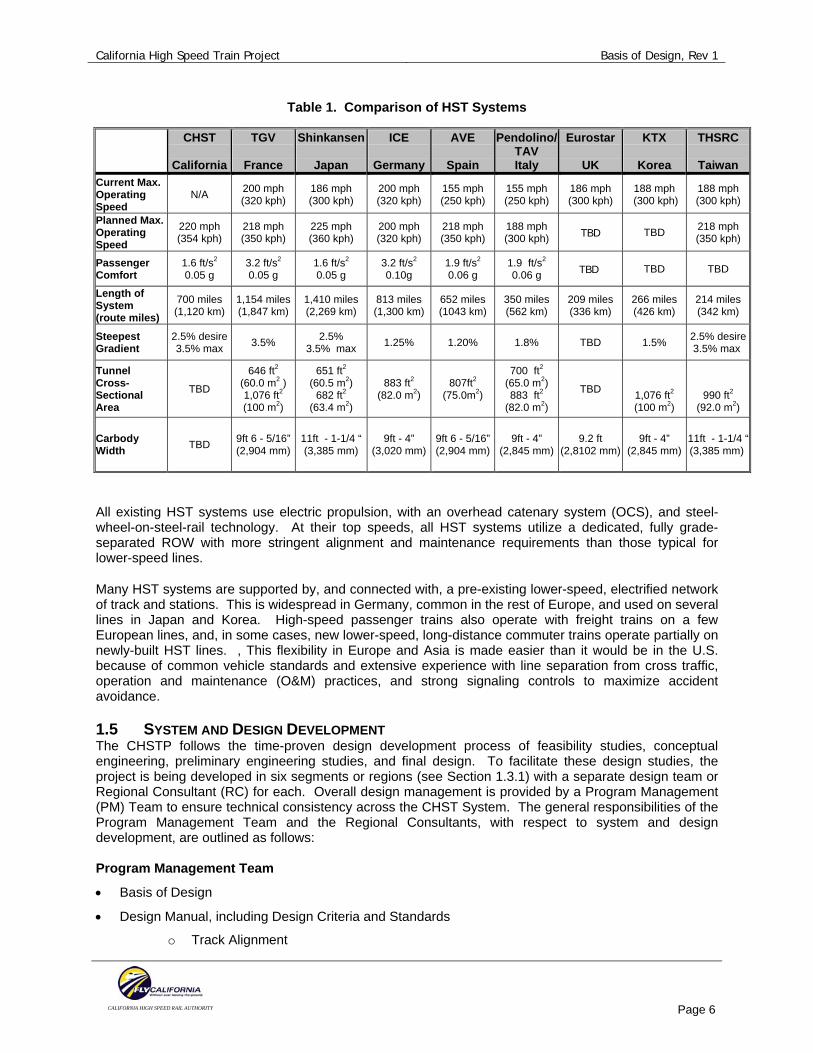
Table 1. Comparison of HST Systems
All existing HST systems use electric propulsion, with an overhead catenary system (OCS), and steel-wheel-on-steel-rail technology. At their top speeds, all HST systems utilize a dedicated, fully grade-separated ROW with more stringent alignment and maintenance requirements than those typical for lower-speed lines.
Many HST systems are supported by, and connected with, a pre-existing lower-speed, electrified network of track and stations. This is widespread in Germany, common in the rest of Europe, and used on several lines in Japan and Korea. High-speed passenger trains also operate with freight trains on a few European lines, and, in some cases, new lower-speed, long-distance commuter trains operate partially on newly-built HST lines. , This flexibility in Europe and Asia is made easier than it would be in the U.S. because of common vehicle standards and extensive experience with line separation from cross traffic, operation and maintenance (O&M) practices, and strong signaling controls to maximize accident avoidance.
1.5 SYSTEM AND DESIGN DEVELOPMENT The CHSTP follows the time-proven design development process of feasibility studies, conceptual engineering, preliminary engineering studies, and final design. To facilitate these design studies, the project is being developed in six segments or regions (see Section 1.3.1) with a separate design team or Regional Consultant (RC) for each. Overall design management is provided by a Program Management (PM) Team to ensure technical consistency across the CHST System. The general responsibilities of the Program Management Team and the Regional Consultants, with respect to system and design development, are outlined as follows: Program Management Team
• Basis of Design
• Design Manual, including Design Criteria and Standards
o Track Alignment
CHST
California
TGV
France
Shinkansen
Japan
ICE
Germany
AVE
Spain
Pendolino/TAV Italy
Eurostar
UK
KTX
Korea
THSRC
Taiwan Current Max. Operating Speed
N/A 200 mph (320 kph)
186 mph (300 kph)
200 mph(320 kph)
155 mph(250 kph)
155 mph(250 kph)
186 mph (300 kph)
188 mph (300 kph)
188 mph(300 kph)
Planned Max. Operating Speed
220 mph (354 kph)
218 mph (350 kph)
225 mph (360 kph)
200 mph(320 kph)
218 mph (350 kph)
188 mph (300 kph) TBD TBD 218 mph
(350 kph)
Passenger Comfort
1.6 ft/s2
0.05 g 3.2 ft/s2 0.05 g
1.6 ft/s2
0.05 g 3.2 ft/s2 0.10g
1.9 ft/s2 0.06 g
1.9 ft/s2 0.06 g TBD TBD TBD
Length of System (route miles)
700 miles (1,120 km)
1,154 miles (1,847 km)
1,410 miles (2,269 km)
813 miles (1,300 km)
652 miles (1043 km)
350 miles (562 km)
209 miles (336 km)
266 miles (426 km)
214 miles (342 km)
Steepest Gradient
2.5% desire 3.5% max 3.5% 2.5%
3.5% max 1.25% 1.20% 1.8% TBD 1.5% 2.5% desire3.5% max
Tunnel Cross-Sectional Area
TBD
646 ft2 (60.0 m2 ) 1,076 ft2 (100 m2)
651 ft2 (60.5 m2)
682 ft2 (63.4 m2)
883 ft2 (82.0 m2)
807ft2 (75.0m2)
700 ft2 (65.0 m2) 883 ft2
(82.0 m2)
TBD
1,076 ft2 (100 m2)
990 ft2
(92.0 m2)
Carbody Width TBD 9ft 6 - 5/16”
(2,904 mm) 11ft - 1-1/4 “ (3,385 mm)
9ft - 4” (3,020 mm)
9ft 6 - 5/16”(2,904 mm)
9ft - 4” (2,845 mm)
9.2 ft (2,8102 mm)
9ft - 4” (2,845 mm)
11ft - 1-1/4 “ (3,385 mm)

California High Speed Train Project Basis of Design, Rev 1
CALIFORNIA HIGH SPEED RAIL AUTHORITY
Page 7
o Stations
o Bridge / Elevated Structures
o Tunnels
o Buildings and Facilities
o Drainage and Grading
o Utilities
o Safety and Security
o Geotechnical
o Seismic
• System Level Design
o Rolling Stock Performance
o Train Simulation and Dispatch Modeling
o Traction Power Modeling and Electrification
o Train Control System
o Operations Plan
o Maintenance Plan
• Oversight to ensure technical consistency across the CHST System Regional Consultants
• Conceptual Engineering
• Environmental Technical Studies and Approval
• Preliminary Engineering

California High Speed Train Project Basis of Design, Rev 1
CALIFORNIA HIGH SPEED RAIL AUTHORITY
Page 8
2.0 PERFORMANCE REQUIREMENTS To meet the travel time and service quality goals of the CHSTP, the PM has established performance requirements to guide the development of the CHST System. The ridership and travel time projections for the CHST System will be updated and refined as the segments are further developed during the project-level environmental and engineering studies. Additional operational modeling efforts will be concurrent with the preliminary engineering studies and will be the primary tool to confirm performance levels of the CHST System. 2.1 SYSTEM CAPACITY AND RIDERSHIP FORECASTS The objective of the CHST System is to maximize ridership and revenue potential by meeting the required travel times and reaching population/employment areas within the state. In 2007, new baseline ridership and revenue projections were completed for the year 2030. Depending on the alignment (Pacheco or Altamont), and the future cost of auto and air travel, between 88 and 117 million annual passengers are expected to use network services. The current financial planning work (2007 and 2008) will examine the impact of higher fares, as well as the ridership and revenue estimates for the initial phase of the CHSTP, from San Francisco downtown to Anaheim. The 2030 ridership forecasts are also critically dependent on the frequency of station stops and the speed of trips with stops. An intricate operating pattern of over 220 trains produces the ridership forecast, with a mix of local and express trains. The operating pattern requires local trains to be overtaken at full speed by non-stop through trains, which is possible at all intermediate stations except the LA Union Station. Peak hour operations are more frequent than off-peak, and reach a maximum of 12-15 trains per hour, per direction, between Palmdale and Bakersfield and between the Bay Area and the Central Valley. The design of the double track infrastructure should allow for as many as 20 trains per hour, at maximum allowable speed, without express trains being impacted (slowed down) by local trains reducing their speed for station stops. It is currently estimated that a fleet of 75 to 80 train sets including spares, will be required to run this level of service. The CHST System will maximize connectivity and accessibility by interfacing with commercial airports, mass transit, and the highway network. Furthermore, the CHST System will be designed so that it is compatible with existing and future-planned development. The proposed service will be updated as new ridership data becomes available. 2.2 TRIP TRAVEL TIMES Past forecasting efforts have shown that the CHST System is economically feasible if there is a high frequency level of service (LOS) and if operations are efficient enough to make it highly competitive with travel by air or auto. Based on the program-level engineering studies, the CHST System is capable of trip times that are competitive with other modes of intercity travel in California. As shown in Table 2, travel between downtown San Francisco and downtown Los Angeles, utilizing the proposed CHSTP, is currently forecasted to take just over two and a half hours. The table below represents the latest trip run times and, although these figures are likely to change in minor ways as the project develops, demonstrates the high LOS and competitive travel times to be expected of the CHSTP.

California High Speed Train Project Basis of Design, Rev 1
CALIFORNIA HIGH SPEED RAIL AUTHORITY
Page 9
Table 2. CHST System Intercity Trip times
Source: Draft Bay Area to Central Valley HST Program EIR/EIS, Section 4.3 2.3 SERVICE DESCRIPTION 2.3.1 Level of Service The CHST System will be developed in a manner capable of accommodating a wide range of service types, from express services between northern and southern California to localized regional trips. The types of services currently in the operating pattern include:
• Express: Trains running from Sacramento, San Jose, or San Francisco to Los Angeles and San Diego without intermediate stops (except Los Angeles) between origin and destination.
• Semi-Express: Trains running from Sacramento, San Jose, or San Francisco to Los Angeles and San Diego with intermediate stops at major Central Valley cities such as Modesto, Fresno, and Bakersfield, and Los Angeles.
• Suburban-Express: Trains running between northern and southern California and locally within the major metropolitan areas (i.e., the San Francisco Bay Area and the Los Angeles area) at the beginning and end of the trip, without intermediate stops in the Central Valley.
• Local: Trains stopping at all intermediate stops with the potential for skipping stops to improve service (depending on demand).
• Regional: Trains running “local” that begin or end in the Central Valley (Sacramento to San Francisco service and early morning service from the Central Valley to San Francisco or Los Angeles/San Diego), operating mostly during commute hours.
2.4 DESIGN/OPERATING SPEEDS The speed criteria for the system are as follows:
• Maximum Design Speed: The design of the CHST System will incorporate a maximum design speed of 250 mph (402 kph) where cost-effective and environmentally feasible.
• Maximum Operating Speed: The design of the CHST System will incorporate a maximum operating speed of 220 mph (354 kph) where geometry and operational conditions permit.
It is important to note that the maximum operating speed cannot be achieved on some portions of the proposed alignment, particularly the heavily constrained urban areas. For example, speeds in urban

California High Speed Train Project Basis of Design, Rev 1
CALIFORNIA HIGH SPEED RAIL AUTHORITY
Page 10
areas may be constrained to a maximum of 125 mph (201 kph). Taking into consideration geometric (horizontal/vertical alignment), geographic, and environmental constraints (visual or noise/vibration), the average operating speed across the route is anticipated to be approximately 155 mph (250 kph).
2.5 ENVIRONMENTAL CONSIDERATIONS The CHST System will be designed to minimize environmental issues. The following is a list of actions to consider, but that the project is not limited to, including:
• Minimize impacts on natural resources
• Minimize impacts on social and economic resources
• Minimize impacts on cultural and parks/wildlife refuge resources
• Maximize the avoidance of areas with geologic and other soils constraints
• Maximize the avoidance of areas with potentially hazardous materials
• Avoid the infiltration of ground or surface waters
• Avoid dividing wildlife populations or habitat areas and/or impeding wildlife migration corridors. Underpasses, overpasses, and other appropriate passageways should be designed to avoid, minimize, and/or mitigate impacts to wildlife movement
The Authority will work closely with regulatory agencies to develop acceptable specific design and construction standards for stream crossings, including, but not limited to, maintaining open surface crossings (bridged versus closed culverts), infrastructure setbacks, erosion control measures, sediment control, excavation, and fill practices, and other best management practices (BMP). 2.6 PHYSICAL REQUIREMENTS The CHST System will meet the following requirements. General
• Electrified Steel-Wheel-On-Steel-Rail very high speed (VHS) system
• Capable of safe, comfortable, and efficient operation at maximum speeds of 220 mph (354 kph) Infrastructure
• Fully grade-separated track
• Fully dual-track mainline with off-line station stopping tracks
• Track geometry that maintains passenger comfort (smoothness of ride) with a lateral acceleration equal to or less than 0.05 g
Systems
• Electric propulsion system
• Fully access-controlled railway with intrusion monitoring systems
• Equipped with high-capacity and redundant communications systems capable of supporting fully automatic train control
California High Speed Train Project Basis of Design, Rev 1
CALIFORNIA HIGH SPEED RAIL AUTHORITY
Page 11
Rolling Stock
• Sixteen-car trainsets, approximately 400 m (1320 feet) in length
• Approximately 1000 passengers per train capacity for 16 car trainset
• Accommodate Asian and European technology
Operations
• Capable of operating at 3-minute headways
• All-weather/all-season operation
• Capable of accommodating normal maintenance activities without disruption to daily operations
• Capable of operating on shared-use corridors (such as LOSSAN and Caltrain)
• Capable of operating parcel and special freight service as a secondary use

California High Speed Train Project Basis of Design, Rev 1
CALIFORNIA HIGH SPEED RAIL AUTHORITY
Page 12
3.0 INFRASTRUCTURE The infrastructure for the CHST System will be designed to maximize the investment, while avoiding and minimizing potential negative environmental consequences. 3.1 TRACK ALIGNMENT The track alignment will be designed to promote or achieve the following: • Maximum system safety
• Acceptable passenger comfort
• Minimum wear on rails and wheels for rail technologies
• Compatibility with rolling stock (vehicles) characteristics
• Maximum operating speed and efficiency Proposed CHST alignment options are generally established along or adjacent to existing rail and highway transportation facilities, where possible, instead of creating new transportation corridors. Alignments will be grade separated at all rail, highway, and roadway crossings. The HSR technology requires a dual-track mainline system to support the ridership volumes, frequency of service, scheduling flexibility, and delay recovery required for the proposed system. The dual-track mainline will be maintained through station areas to allow for run-through or express service. Off-line stopping tracks are provided at all intermediate stations, except Los Angeles and San Jose, where all trains will stop. Adequate clearances will be provided to assure the safe passage of trains, access to disabled trains, and safe conditions for maintenance personnel and passenger evacuation. 3.1.1 Tunneling The CHSTP will traverse mountainous terrain and other areas with difficult topographies, which will require tunneling to meet grade requirements for the project. These mountain crossings and resulting tunnels represent one of the key challenges for the construction of the CHSTP. A relatively high degree of certainty and confidence on the feasibility of the proposed tunneling and the associated costs is needed to support the process for establishing preferred alignments. In general, due to the cost impact of tunneling, it is the Authority’s goal to thoroughly evaluate the amount of tunneling needed for the CHSTP. The designers will consider and document the trade-offs associated with lower grade/longer tunnels versus higher grade/shorter tunnels for the PM’s consideration. Such factors as fire and life safety requirements, travel time impacts, power usage, costs, construction feasibility, and efficiencies and train operations are to be included in these analyses. During the program-level EIR/EIS, a double-track tunnel cross sectional area was developed based on a review of the aerodynamic requirements for HSR operation in Europe and Asia. Similarly, single-track tunnels, based on European and Asian experience, were reviewed. The following requirements will be applied to tunneled segments of the CHST System: • Due to higher costs and construction time, the amount of tunneling required for the project will be
reduced.
• Due to construction efficiency and fire and life-safety issues, twin single-track tunnels are to be assumed for lengths of less than 6 miles.

California High Speed Train Project Basis of Design, Rev 1
CALIFORNIA HIGH SPEED RAIL AUTHORITY
Page 13
• The determination of tunnel cross sections are to consider aerodynamic requirements for the proposed CHSTP, evaluating existing Asian and European HSR systems.
• All tunnels should be fully lined for water tightness and structural and aerodynamic factors. 3.1.2 Corridor Grade Separation There will be no at-grade crossings permitted on the dedicated CHST System so as to support the safety and performance requirements. Grade separation projects required for the CHST System will be set as a high priority, particularly those grade separation projects that affect existing and planned rail and road facilities. Early implementation of the grade separation projects can improve local safety, circulation, and reduce air pollution and noise impacts. 3.1.3 Seismic Design Reliability Continuing revenue operation of the CHST System during and after a strong seismic event is a priority of the Authority. Because of the high likelihood of major seismic activity during the life of the facility, preventive measures will be made to avoid an unnecessarily long shut-down of the system after a major earthquake. To this end, in the determination of the horizontal and vertical alignment, it is desirable to cross major fault zones at-grade where mitigating designs can be more cost-effectively employed. Seismic performance will be considered in the design of CHST System structures. The seismic performance levels described below are being developed based on worldwide experience of existing HSR systems in seismically active zones. System Seismic Performance The goal of the CHSTP, in terms of structural performance during a seismic event, is to safeguard against major failures, loss of life, and to prevent a prolonged interruption of CHST System operations caused by structural damage. In order to achieve this, the following three measures have been established.
• Ensure that CHST System facilities are able to undergo the effects of the Design Base Earthquake
(DBE) without collapse and that all damages are repairable.
• Ensure that the CHST System will be able to operate safely, at the maximum design speed, without the yielding of reinforcement steel or structural steel subjected to the Lower-level Design Basis Earthquake (LDBE).
• Ensure that buildings and equipment are able to meet the Basic Safety Objective (BSO) defined in FEMA 356.
Bridge Seismic Performance There are two basic performance levels to which CHSTP bridges and aerial structures will be designed, including: • Safety Performance Level (SPL): Limiting structural damage to be repairable such that train
operations can resume immediately, or within a reasonable amount of time, following the DBE. The SPL requires that the bridges and aerial structures be capable of carrying all operating and/or service loads following the DBE seismic event. As a general guideline, the piles in aerial guideway pier foundations shall not experience significant damage. Limited rocking of the structure is allowed for piers founded on spread footings only.
• Operability Performance Level (OPL): Limiting structural damage to be minimal such that trains can operate safely, at the maximum operating speed, under the LDBE. Structures carrying CHST tracks should remain essentially elastic under the LDBE. Rocking of structures on either spread footing or pile foundations is not allowed.

California High Speed Train Project Basis of Design, Rev 1
CALIFORNIA HIGH SPEED RAIL AUTHORITY
Page 14
Displacement of track should be checked to ensure that it remains within the allowable values for a LDBE, so that the trains can brake safely to a stop from the full operating speed. The structures that are supporting the tracks will be designed with the capacity of being readjusted for the permanent deformation or displacement due to a LDBE.
3.1.4 Right-of-Way The implementation of the CHSTP will require ROW for the basic footprint of the system and for traction power supply facilities. Additional needs may influence the extent of the ROW envelope necessary for considerations such as, topography, soils, groundwater levels, noise receptors, cut-and-fill slopes, drainage, retaining walls, access/service roads, utilities, operating speeds, and construction methods. Minimum ROW requirements are as follows: • 30.4 m (100 ft) corridor in less developed areas
• 15.2 m (50 ft) corridor in congested corridors
• 9,290 m (100,000 sq ft) for traction power supply stations
• 465 m (5,000 sq ft) for switching stations
• 370 m (4,000 sq ft) for paralleling stations
The CHSTP will be designed to reduce or avoid impacts associated with construction period access roads. Access requirements in and around sensitive areas will consider alternate means of access for drilling equipment, such as, helicopter transport and use of the new rail infrastructure (in-line construction) to haul excavated material and material as it is constructed. It is the Authority’s intent to minimize the impact footprint and associated direct impacts to farmland, parkland, and biological and water resources by using existing transportation corridors. Wherever possible, the Authority is committed to pursuing an agreement with existing owners/rail operators to place the CHST alignment within existing rail ROW (to avoid and/or minimize potential impacts to agricultural land and other natural resources). The public agencies and private-sector companies that the Authority is seeking an agreement of cooperation with include, but are not limited to: • BNSF (Burlington Northern Santa Fe)
• UPRR (Union Pacific Railroad)
• Amtrak
• Metrolink
• Caltrain
• NCTD (North County Transit District)
• LACMTA (LA County Metropolitan Transportation Authority)
• OCTA (Orange County Transportation Authority)
• RCTC (Riverside County Transportation Commission)
• Caltrans
• CPUC (California Public Utilities Commission)
• FRA (Federal Railroad Administration)
3.2 STATIONS It is the Authority’s objective to minimize impacts associated with growth by selecting multi-modal transportation hubs as potential CHSTP stations. These locations should maximize access and connectivity, and facilitate transit oriented growth (TOD). The key factors considered in identifying potential station stops during the program-level EIR/EIS include speed, cost, local access times, potential connections with other modes of transportation, ridership potential, and the distribution of population and major destinations along the route. The CHST System will be compatible with local and regional plans

California High Speed Train Project Basis of Design, Rev 1
CALIFORNIA HIGH SPEED RAIL AUTHORITY
Page 15
that support rail systems and TOD, offering opportunities for increased land use efficiency. Intermodal connectivity with local and commuter rail systems will also be supported. The station locations identified are all multi-modal transportation hubs providing links to local and regional transit, airports, and highways. There are two principal types of stations: terminus and intermediate. Terminus stations are those where all trains are planned to stop upon arrival. The ultimate configuration of each station location will be refined during the design process and meet all requirements set forth by the American with Disabilities Act (ADA). 3.2.1 Track and Platform Configuration Station platforms are assumed to have a minimum length to accommodate a sixteen car train, approximately 400 meters (1320 feet). This platform length allows for flexibility in operations by allowing for variation in trainset composition and potential temporary storage at station platforms. Station platforms are assumed to have a minimum width of 30 feet (9 meters), inclusive of vertical access. Some flexibility may be required at terminal locations and will be considered based on the platform capacity needed at each location and the effect of sizing deviations on the operational performance of the system. The specific station configuration will be defined as necessary to accommodate train and passenger volumes and frequency required to serve the forecasted demand. Overall station size would also consider access facilities, parking facilities, and passenger facilities. 3.2.2 Terminal Stations Terminus stations are those where all trains are planned to stop upon arrival and perhaps lay-over during non-peak periods. The following stations are designated as terminal stations:
• Sacramento
• San Francisco
• Oakland
• San Diego
• Orange County
3.2.3 Intermediate Stations Intermediate stations are defined as “line” stations providing service along the dedicated CHST route and located between San Diego, Los Angeles, Sacramento, and San Francisco/Oakland. Intermediate stations will provide off-line passenger platforms allowing for pass-through express services on the dual-track mainline. The following stations are designated as possible intermediate stations: • Stockton
• Modesto
• Merced
• San Francisco Airport
• Redwood City/Palo Alto
• San Jose
• Oakland Airport
• Union City
• Fresno
• Visalia
• Bakersfield
• Palmdale Airport
• Los Angeles
• Sylmar
• Burbank
• Norwalk
• City of Industry
• Ontario Airport
• Riverside
• Murrieta
• Escondido
• Universal City
California High Speed Train Project Basis of Design, Rev 1
CALIFORNIA HIGH SPEED RAIL AUTHORITY
Page 16
Due to the size and location in the CHST System, the Los Angeles and San Jose Stations (designated as intermediate stations) will require configurations that are capable of supporting both future growth and potential modifications to the conceptual service plan comparable to a terminal station facility. Storage requirements for these two stations may be greater than for the other intermediate stations and the location of such storage needs to be analyzed for feasibility. For the Bay Area to Central Valley area, the stations will be updated pursuant to ongoing program-level EIR/EIS in this area. 3.2.4 Shared Use Corridors It should be possible to integrate the CHST System into existing conventional rail lines in congested urban areas, however, only upon resolution of potential equipment and operating compatibility issues working in cooperation with the FRA. A station in this type of shared-use condition would accommodate both the conventional commuter rail service and the CHST System. Shared-use stations are anticipated in the following rail corridors: • CALTRAIN Corridor: Corridor between San Francisco and San Jose, operated by the Peninsula
Corridor Joint Powers Board, providing Caltrain commuter rail service.
• LOSSAN Corridor: The Los Angeles to Orange County Corridor, operated by the Southern California Regional Rail Authority (SCRRA), providing Metrolink commuter rail service, passenger service by Amtrak, and freight by the Burlington Northern Santa Fe (BNSF) Railroad. It should be noted that while freight service is provided in the LOSSAN Corridor, freight and CHST service will operate on separate tracks.
The specifics for shared-use stations will be defined during the project-level Environmental Review process, and further refined during Conceptual and Preliminary Engineering. 3.2.5 Station Area Amenities Intermodal Connectivity -- Station area amenities should be designed with a focus on convenience and ease of transfer to and from the CHST System and to other modes of transportation. The specific features and amenities in and surrounding each station will vary, depending on passenger demand and station type (i.e., terminal or intermediate). Parking -- Depending on the station location, ridership demand, availability of intermodal connections, mix of trip purposes served, local land use, parking policies, and other site specific factors, passenger parking facilities may require a significant amount of land area. It is anticipated that the parking demand at CHST stations would closely resemble that of airports (given that the CHST System provides intercity service). The number of parking spaces will be estimated using factors such as daily boardings, percent of passengers in the peak hour, average passengers per vehicle, vehicle headway, and a length of stays. The refinement of station parking projections will be progressed during the preliminary engineering phase of the project. Currently, it is assumed that paid parking will be provided at the stations at market rates (i.e., no free parking). 3.2.6 Passenger Facilities The configuration of station passenger facilities will depend upon a multitude of variables including, station location, ridership demand, interaction with intermodal connections (if available), mix of trip purposes served, local land use, and building codes requirements. The develop of passenger facilities will also consider the need for waiting areas, concourses, ticketing, restrooms, as well as other support services to improve the passenger experience of the CHST System.

California High Speed Train Project Basis of Design, Rev 1
CALIFORNIA HIGH SPEED RAIL AUTHORITY
Page 17
3.3 VEHICLE STORAGE AND MAINTENANCE FACILITIES 3.3.1 Storage and Maintenance Facilities Maintenance and storage facilities will be necessary to support the CHST System fleet operation. The storage and maintenance facilities will coincide with an operating and maintenance concept that is supportive of the desired LOS and reliability. Maintenance facilities and rail vehicle storage yards will be electrified and will utilize a dedicated traction power supply station. Station area storage tracks will be electrified and may be supplied from an adjacent main line OCS. Because of the constraints from existing urban development around some of the terminus station locations, it is assumed that only minimal storage and very basic service and inspection will be integrated into the station infrastructure. The majority of the fleet storage, service, inspection, maintenance, and repair requirements are assumed to be supported at two types of independent facilities that are defined and generally sited below.
• Fleet storage/service and inspection/light maintenance (locations near each terminal station and the Los Angeles station)
• Main repair and heavy maintenance (one location along the entire alignment) Each type of maintenance facility will have set function requirements and storage capability. 3.3.2 Fleet Storage/Service and Inspection/Light Maintenance Facility This type of facility will include tracks for “lay-up” (parking) for trainsets, a service and inspection facility for inspection and light maintenance, and a train washer located on the yard approach track for exterior cleaning prior to daily train storage. There will also be areas for employee administration and comfort. The remaining types of maintenance functions will be provided at the main repair and heavy maintenance facility. These facilities will be provided near each terminal station and at the Los Angeles station. 3.3.3 Main Repair and Heavy Maintenance Facility One main repair and heavy maintenance facility will be necessary and will be sited near the main trunk line of the system (between Los Angeles and Merced), where the majority of trains will pass on a daily basis. The location of this facility should consider access and availability of a workforce to support the facility. The following are types of areas, shops, and functions required for the main repair and heavy maintenance facility:
• Wheel Truing Area
• Service and Inspection (S&I) Area
• Running Repair Facility
• Support Shops
• Material Inventory and Distribution Area
• Component Change-Out Area
• Overhaul Area
• Heavy Repair Facility
• Exterior Maintenance Shop (body shop)
The facility sizing will be based on the greatest potential need (fleet size) associated with the CHST System operation, which will depend on train consist size, mix of services, and specific start-up assumptions. The fleet size is subject to change pending availability of updated ridership data and service requirements.

California High Speed Train Project Basis of Design, Rev 1
CALIFORNIA HIGH SPEED RAIL AUTHORITY
Page 18
3.3.4 Trainset Storage Requirements Based on earlier operations plan, the following trainset storage requirements have been established. The information can be used as an order of magnitude to advance engineering studies for the project.
• Sacramento (9 trains)
• San Francisco/Oakland (15 trains)
• San Diego (21 trains)
• Los Angeles (4 trains)
• Fresno (2 trains)
• Bakersfield (2 trains)
Additional program-level studies, however, have identified an increase in the projected annual ridership (between 88 to 117 million passengers), altering the total number of trainsets required. Based on the updated figures, it is estimated that up to 80 trainsets will be needed to facilitate the future demand. Additional storage requirements will be needed to accommodate this change. 3.3.5 Maintenance of Way Facilities will be provided for the storage of maintenance-of-way (MOW) equipment at regularly-spaced intervals, including, areas for the storage of extra parts associated with the track way and systems and associated MOW personnel facilities. 3.3.6 Pocket Tracks Storage capacity along the CHST System will be provided in the form of pocket tracks, which may be located at regularly-spaced intervals and used to store disabled trains and help maintain the LOS for the System. Proposed locations will be analyzed for compliance with the proposed service plan.

California High Speed Train Project Basis of Design, Rev 1
CALIFORNIA HIGH SPEED RAIL AUTHORITY
Page 19
4.0 SYSTEMS This section describes the basis for the systems components of the CHST System. During the design process, all facility sizing and spacing will be verified by computer modeling/simulation efforts, based on planned headways, expected train performance, specific equipment specifications, and service levels. As noted in Section 1.5 System Design and Development, the Program Management Team will provide system-level design for the electrification and train control systems to ensure technical consistency across the CHST System. 4.1 ELECTRIFICATION / TRACTION POWER SUPPLY SYSTEM The traction power supply system (TPSS) will be a 2 x 25kV autotransformer system with center-feed and/or single-end feed segments, utilizing supply stations that have utility supply circuits, switching stations with autotransformers, and paralleling stations with autotransformers. The TPSS will be able to support the ultimate LOS proposed without degradation when any single power supply system component is out of service. This system will include:
• Power supply redundancy at supply stations through the use of two independent utility supply
circuits and two power supply transformers, each rated to supply the TPSS load
• Supply station switchgear to support this redundancy
• Supply stations located at intervals along the CHST ROW. Switching stations, with at least two autotransformers, will also be located approximately mid-distance between the supply stations
• Paralleling stations, with at least one autotransformer, will be located approximately equally spaced between the supply stations and switching stations
The PM will prepare a traction power model based on the proposed train timetable for the CHST System. The model will identify the electrification requirements for establishing the size and location of supply stations, switching stations, and paralleling stations. 4.2 OVERHEAD CONTACT SYSTEM The auto-tensioned OCS will be a simple two-wire system supported by cantilevers and attached to track-side poles (and/or gantries) and will be suitable for: • Anticipated operating speeds of trains utilizing multiple pantographs (maximum 220 mph operations)
• Sectionalized to meet the requirements of the TPSS
• Conductor sizes suitable for the ultimate LOS proposed
4.3 TRACTION POWER RETURN SYSTEM The traction power return system will return traction power supply current to the center tap of the autotransformers at supply, switching, and paralleling stations. The connections between the running rails and the autotransformer center tap bus will be made via a direct rail connection or impedance bonds at each track depending on the train control system used. In addition to the traction power return system, the CHST System will have a grounding and bonding system that will include, at a minimum, buried ground grids at supply, switching, and paralleling stations, grounded operator platforms at track-side switchgear locations, aerial ground wires interconnecting OCS support structures, and buried counterpoise wires in specific areas. The elements of the grounding and bonding system will be connected to the rail return system and autotransformer center tap bus.
California High Speed Train Project Basis of Design, Rev 1
CALIFORNIA HIGH SPEED RAIL AUTHORITY
Page 20
4.4 TRAIN CONTROL SYSTEM The train control system will safely support the ultimate LOS proposed for the grade-separated CHST System and will address the following: • Train operating speed of 220 mph (354 kph) maximum
• Safe braking criteria in exclusive guideway
• Safe braking criteria in shared-use corridors
• Shared-use corridor electrification equipment specifications
• System operations plan specific requirements
• Design headway of 3 minutes
• Braking criteria for Caltrain or other railroad in shared-use corridors
• Caltrain electrification
• Operations plan There are a number of issues that will be addressed with the FRA in the development of the CHST System, including:
• Compliance with 49 CFR Parts 209, 234, and 236 “Standards for Development and Use of Processor-Based Signal and Train Control Systems,” specifically, 236 sub part H
• Broken Rail Detection (fixed block train detection)
• Braking model that considers lead train at zero velocity 4.5 COMMUNICATIONS The CHST System will have a Central Control Facility (CCF) for supervision control and monitoring of the CHST System operation. The CCF will serve the following functions:
• Central supervision and train dispatch facility
• Central supervision and power dispatch facility
• Hub for the CHST System’s safety/security functions
• Real-time location of all CHST vehicles
• Collect and record CHST operations data
• Collect and record supervision data (such as cameras)
• Central intrusion detection
• Access control
• Seismic detection
• Wind detection
• Supervisory control and data acquisition (SCADA)
• WI-FI and, if appropriate, Wi-MAX compatibility All information will be received and recorded. Any incidents will be handled and routed through the CCF. Without main electrical power, the CCF, and any back-up locations provided, will have the ability to maintain full operation capability using an uninterruptible power supply system (UPS) for a period of four hours. The CCF is envisioned to be co-located with the main repair and heavy maintenance facility.

California High Speed Train Project Basis of Design, Rev 1
CALIFORNIA HIGH SPEED RAIL AUTHORITY
Page 21
5.0 ROLLING STOCK The CHST vehicles will be of steel-wheel-on-steel-rail very high-speed (VHS) technologies, using distributed power cars and a catenary capable of maximum operating speeds of 220 mph (354 kph). The trains must be capable of integrating into existing conventional rail lines where shared-use is anticipated in the LOSSAN and JPB Caltrain corridors. Shared-use is also being explored in the Los Angeles to San Diego segment, particularly, for the portions in Los Angeles and Riverside Counties. The PM has set forth the following capacity and performance objectives for the HST cars:
• Capable of maximum operating speeds of 220 mph (354 kph)
• Approximately 1000 passengers per train capacity for 16 car trainset
• Pressure-sealed trainsets to maintain passenger comfort regardless of aerodynamic changes along the line
5.1 COMPARISON OF EUROPEAN & ASIAN HIGH SPEED TRAIN VEHICLE CHARACTERISTICS 5.1.1 Factors Considered/Observations There is worldwide experience for safe and reliable HST revenue service in Europe and Asia that can be consulted during the development of the CHST System vehicle. The table below summarizes the parameters considered for the vehicle performance assumptions used during the program-level EIR/EIS.
Table 3. Comparison of Representative Trainset Technologies
L= Locomotive T = Trailer M = Motor Car
During the project specific level studies, additional trainsets will be considered including the AVE Velaro which are planned for running at speeds of up to 350 kph (218 mph) in revenue service operations, and the Shinkansen Fastech 360, a prototype train designed for speeds up to 405 kph (253 mph) and anticipated to be in production in 2011.
Parameters Considered
Alstom TGV
(Duplex)
Siemens ICE 3
Japan Series 500
Japan Series 700
Train Configuration L+8T+L 6M + 6T 8M 6M+2T (1/2 Max Train) (1/2 Max Train) (1/2 max Train)
Train dimensions Length (ft) 660 985 669 669 Width (ft) 9.5 9.5 11.15 11.15 Height (ft) 13.5 12.8 12.1 12.1
Train Weight (tons) 380 662 344 392 Seating
Total Seating Cap./ Train as described 516 687 662 662 Total Seating Cap./ Train for 16 car
equivalent 1032 916 1324 1324
Axles / Train Motored Axles 8 24 32 24
Total Axles 26 48 32 32 Train horse power 12,000 10,724 12,200 8,850
Max design speed (mph) 200 205 227 218
Max in-service speed (mph) 186 186 186 177

California High Speed Train Project Basis of Design, Rev 1
CALIFORNIA HIGH SPEED RAIL AUTHORITY
Page 22
5.2 MODELING EFFORT During the programmatic level studies, a simulation modeling effort was performed in order to confirm intercity trip times and obtain optimal theoretical trip times for express trains. Train performance calculations were prepared using published trainset performance specifications including, tractive effort and dynamic braking characteristics to replicate the dynamics of each train. This simulation model will be updated during the project specific level studies and based on updated ridership data currently under development. For the purposes of the train simulation model runs prepared during the programmatic level studies and needed to derive the current operations plan, the trainset performance specifications (i.e. tractive effort curve, braking effort curve, weight, etc.) were based on a 12-car, Siemens ICE-3 consist. This configuration was used as it most closely achieves the combination of capacity and performance objectives for the proposed CHST System. This representative trainset was used in the model to test the route in the Train Performance Calculator (TPC) simulations. The train performance characteristics will be revisited during the design phase to take into account technological advances of new rolling stock. The model simulates HST operations based on trainset performance characteristics for a specified alignment including, different geometric parameters and infrastructure configurations. The TPC is used to compute optimal (minimum) run times and operating speeds for trains running from one specified point to another, over the rail network, without interference from other trains (at a region-by-region level and systemwide). The key inputs and assumptions for the modeling effort include:
• Train characteristics and specifications
• Alignment and station locations
• Station configuration
• Maintenance and storage facilities
• Service plan As updated ridership data becomes available, the modeling effort will be updated to reflect changes in ridership. These updates will also incorporate updated train performance data, revised track alignment geometry, rolling stock maintenance requirements (i.e. contact time for inspections, maintenance, and repairs), and identified operating restrictions. 5.3 FLEET SIZE/VEHICLE SPARE RATIO For previous forecasts during the programmatic level studies, the potential fleet size ranged from 38 to 55 trainsets (including spares) and depended on train consist size, mix of services, and specific start-up assumptions. For the purpose of fleet size determination and the sizing of facilities, a 10% spare ratio was assumed. Given the updated ridership numbers, this fleet size could be as large as 80 trains, and will be reviewed and updated as part of the ’07 –’08 financial planning.

California High Speed Train Project Basis of Design, Rev 1
CALIFORNIA HIGH SPEED RAIL AUTHORITY
Page 23
6.0 MAINTENANCE REGIME This section provides the PM’s maintenance regime for the operation of the CHST System. 6.1 CALIFORNIA HIGH SPEED TRAIN MAINTENANCE PHILOSOPHY Existing practices on HST lines worldwide establish standard criteria for performance of maintenance activities that include different levels during and in parallel of the installations and commissioning of the HST network systems. This approach is necessary to ensure that maintenance requirements are built into the infrastructure and operations of the CHST. The maintenance of the CHST System is comprised of two components: maintenance of the rolling stock and maintenance of the infrastructure (also known as MOW). 6.1.1 Maintenance of Rolling Stock In order to maintain the anticipated LOS, the CHST System rolling stock will undergo scheduled maintenance to assure the quality of train service. The maintenance of the rolling stock for the CHST System will be pursuant to the following four levels of maintenance:
• Level 1: A visual walk-thru examination, based on a set interval of miles traveled. This will also include external and internal cleaning of the vehicles. This level of the maintenance program may be conducted at a terminal station.
• Level 2: Periodical monitoring of vehicle components, with the interval dependant on the item to be inspected. This inspection will entail opening of panels as needed to perform the required inspection and may include:
• Rolling gear inspection
• Comfort Inspection (passenger compartment facilities)
• General inspection
This level of the maintenance program will be conducted at a light maintenance facility.
• Level 3: Based on a mix of service time and mileage (preventive maintenance) and actual wear (predictive maintenance, replacing worn items):
• Bogies, axles
• Traction motors, pantographs, inverters, and other related components
• HVAC units
• Train control, communications, and signaling systems
This level of the maintenance program will be conducted at a light maintenance facility.
• Level 4: Heavy repairs to the vehicle systems or body shop services to the car body, also will include main transformations on car bodies and train structure lasting days or weeks following several years of revenue service:
• Body shop repairs after accidents
• Renewal and to-date arrangements
• General changes on a whole series of trains
This level of the maintenance program will be conducted at a heavy maintenance facility.

California High Speed Train Project Basis of Design, Rev 1
CALIFORNIA HIGH SPEED RAIL AUTHORITY
Page 24
6.1.2 Maintenance of Way The goal of the MOW program will be to ensure that an adequate and cost-effective level of comfort and safety is provided by the CHST System infrastructure. In order to maintain the anticipated LOS, the CHST System MOW will undergo scheduled inspection and maintenance. Maintenance is the summary of all the tasks executed to ensure the safety of operation, long-term preservation of systems, comfort of passengers, and minimized wear on rolling stock. The MOW program includes the maintenance of trackway, civil and earthworks, structures, and all systems. The CHST System MOW program will be divided into two categories: preventive and corrective maintenance. Safety rules will be established to preserve staff’s safety while serving the need to inspect track, energized equipment, and other items under both operating and non-operating conditions, including authorized access within the fenced premises and for on-foot line side inspections. • Preventive Maintenance: The base is to maintain a good quality of performance. Intervals and
periods between preventive maintenance measures are the result of long-lasting experience backed by mathematical modeling of the defect evolution with time and traffic. Inspections can record and measure elements on board trains or other special cars or, by visual inspection /checking (walking the line) and monitoring/inspecting power supply facilities. Generally, a cycle for each maintenance type is defined to measure the evolution on a regular basis and a historic register is established.
• Corrective Maintenance: Designed to re-establish the appropriate level of performance of the infrastructure in terms of safety and comfort. In general, it is performed within track ROW, during the night, during periods outside of revenue service, or in power supply facilities (whilst operating under contingency power supply conditions). In the event of an emergency, corrective maintenance may be done during the day to avoid a permanent speed restriction for the whole day or worse. Corrective work will generally be in three categories: o Light maintenance, not affecting operations, performed during the normal idle periods. o Heavy maintenance, which affects operations, through speed (and therefore capacity) restrictions
or idle periods extensions. o Major renewals with full or partial interruption of traffic, and the mobilization of important
equipment and special machines.

California High Speed Train Project Basis of Design, Rev 1
CALIFORNIA HIGH SPEED RAIL AUTHORITY
Page 25
7.0 OPERATIONS 7.1 SERVICE DESCRIPTION A mix of express, semi-express, suburban-express, local, and regional trains will serve both intercity passengers and long-distance commuters. In order for HST service to be economically viable, the plan will provide frequent and efficient operations. This plan will be developed in the course of FY ’07-’08 financial planning. A brief description is included in Section 2.3 of this report. 7.2 HOURS/DAYS OF OPERATION The CHST System will operate seven days a week. The hours of operation are assumed from 5:00 a.m. to 1:00 a.m., with most passenger service occurring between the peak hours of 6 a.m. to 9 a.m., and 4 p.m. to 7 p.m. The frequency of trains will be updated as part of the revised op plans based on the ridership figures in 2007 7.3 SAFETY/SECURITY The PM intends to operate a secure system similar to Asian and European HST Systems. The safe operation of the CHST System will be of the utmost importance. To this end, the CHST System will be a fully grade-separated and fully access-controlled guideway with intrusion monitoring systems typical of modern HST Systems. The CHST infrastructure (e.g., mainline tracks and maintenance and storage facilities) will be designed to prevent access by unauthorized vehicles, persons, animals, or objects. Allowances for intrusion barriers (fences and walls), state-of-the-art communication, access-control, and intrusion monitoring and detection systems have been made as part of this system. No unauthorized vehicles or pedestrians would be permitted to enter the corridor or cross the tracks at-grade, which would expose them to a possible collision with a train. In addition, the ROW will be fully access controlled (fenced) in areas of high-speed operation to avoid intrusion by pedestrians, wildlife, and livestock. All aspects of the CHST System will conform to the latest Federal requirements regarding transportation security as developed and implemented. Specific security and fire/life safety criteria for the CHST will be developed in separate documents. As these are developed, the CHST will incorporate or exceed the best practices in HST network safety and security used elsewhere in the world. 7.4 PASSENGER SHARED USE/COMPATIBILITY ON CORRIDORS The selected type of HST technology will include steel-wheel-on-steel-rail vehicles capable of meeting the performance criteria while at the same time being able to share tracks (at reduced speeds) with other, compatible services (where the construction of new, separate CHST infrastructure would be infeasible). Shared track operations will use improved rail infrastructure and electric propulsion. Potential shared-use corridors would be limited to sections of the statewide system, with extensive urban constraints. By sharing tracks, the intent is to minimize community and environmental impacts while creating a feeder rail system that allows travelers to easily access the statewide system. Shared-use corridors will meet the following general criteria (in addition to the performance requirements): • Electrification • Uniform control/signal system • Four tracks at stations (to allow for through/express services and local stopping patterns)

California High Speed Train Project Basis of Design, Rev 1
CALIFORNIA HIGH SPEED RAIL AUTHORITY
Page 26
• Possibility of three to four mainline tracks (depending on capacity requirements of HST and other services)
• Physical or temporal separation from conventional freight traffic • Full Grade Separation The segments proposed for shared-use operations are locations that are highly constrained in terms of urban development and alignment geometry. Operating speeds on these segments are significantly constrained; typically, under 125 mph. Sharing rail alignments throughout portions of the system will improve joint facilities, benefiting safety and operations of existing freight, commuter, and conventional rail services. For service on the San Francisco Peninsula (San Jose to San Francisco), integrated (shared-track) service on the Caltrain Corridor will be provided. The CHST trainsets will need to be compatible with the other passenger trains (Caltrain) sharing the tracks. CHST trains may also share tracks with existing services for the LOSSAN corridor from the Los Angeles station to Irvine (although consideration for a dedicated CHST line is currently under review). Sharing tracks with existing services may be required in other heavily urbanized portions of the statewide HST network, such as, San Jose to Oakland and Los Angeles to Riverside. Continued investigation of the rail corridors between Los Angeles and Riverside may include consideration of the potential for sharing tracks with Metrolink. In order for the CHSR system to operate under shared use with other passenger traffic, the CHSTP train sets and train control system will be developed with the agreement of the FRA. However under no circumstances is it considered that the HSR system will operate over any freight lines. 7.4.1 Non-Electrified Freight (BNSF & UPRR) on Electrified High Speed Train
Corridor Shared-use operations with conventional freight traffic will be avoided through the use of physical separation (separate tracks). Operation of conventional full-tonnage freight trains is incompatible with a HST system in California. Operating freight trains at axle loads approaching conventional U.S. axle loads would compromise CHST operating efficiency, maintenance standards/tolerances, and strict safety requirements. Conventional U.S. freight trains also require different track geometry that would increase wear and tear on CHST vehicles. Larger clearances, due to the size of the double or piggyback cargo containers required for freight operations, would also compromise the design of the HST electrification distribution system, under crossings, and tunnels. 7.5 POTENTIAL FUTURE HIGH SPEED FREIGHT SERVICE ON HIGH-SPEED TRAIN
CORRIDORS Due to a clear legislative mandate and limited resources, the Authority has focused its efforts on the implementation of a CHST passenger rail service. The Authority has not undertaken the market studies necessary to define a specific freight system for consideration; therefore, specific freight operating plans and infrastructure will not be addressed as part of this program-level environmental process. However, the engineering parameters established by the PM allow for future implementation of light-weight freight services as the market supports. Further consideration of a specific freight service proposal would be required at the project specific stage of environmental review, prior to implementation. The PM has adopted the policy of excluding the cost of any special freight equipment, or infrastructure, as part of the initial financial and operating plans. Issues regarding light-weight freight service on CHST lines are provided herein merely as a summary of concepts previously studied, which would need to be developed further in order to properly advance freight concepts into the Authority’s business plan.

California High Speed Train Project Basis of Design, Rev 1
CALIFORNIA HIGH SPEED RAIL AUTHORITY
Page 27
7.5.1 Light-Weight/Small Package Service The proposed CHST System could be used to carry small packages, parcels, letters, or any other freight that would not exceed typical passenger loads. This service could be provided either in specialized freight cars on passenger trains or on dedicated lightweight freight trains. In either case, the lightweight freight vehicles would be required to have the same performance characteristics as the passenger equipment. This type of freight would be accommodated without adjustment to the passenger service plan. Loading for this type of small-package would occur at the passenger stations. Package/container versions of the high-speed passenger vehicles can be adapted, without compromising operating capabilities, to handle mail, express parcel, package freight, and other container freight that does not exceed the weight of typical passenger loads. Examples of this type of freight include overnight small packages and mail, distributed by such entities as Federal Express, United Parcel Service, and the U.S. Postal Service. The equipment used for these services must be completely compatible with the passenger equipment and be capable of safely traveling at the top design speeds of the entire high-speed system. This type of equipment could operate as a separate, modified trainset, or, one or more cars could be integrated into a passenger trainset.