chroma meter cl-200a - konicaminolta.com.cn · konica minolta technical note kmse cs-a32t.0100 1....
TRANSCRIPT

KONICA MINOLTA TECHNICAL NOTE KMSE CS-A32T.0100
Chroma Meter CL-200A
Communication Specifications
Issued: June 25, 2010 Konica Minolta Sensing, Inc. 3-91, Daisennishimachi, Sakai-ku, Sakai-shi, Osaka, JAPAN http://www.konicaminolta.com/selector/instruments.html
1
KONICA MINOLTA TECHNICAL NOTE KMSE CS-A32T.0100
2
Notes regarding these specifications: • An understanding of the fundamentals of PC communication is assumed in the
preparation of this document. This document was prepared to explain communication procedures specific to the stated product.
• Reprinting of this document or the information contained herein in its entirety or in part without the express permission of Konica Minolta Sensing, Inc. is strictly prohibited.
• The information herein is subject to change without notice. • Although every effort has been made to ensure the accuracy of the information
contained herein, if you discover an error, missing information, etc. please notify your Konica Minolta Sensing representative.
• Konica Minolta Sensing is not responsible in any way for any losses, damage, etc. resulting from the use of the information contained herein.
• Company names and product names contained herein are trademarks or registered trademarks of their respective companies.

KONICA MINOLTA TECHNICAL NOTE KMSE CS-A32T.0100
Table of Contents
1. Introduction...................................................................................................................5 1.1. About the USB driver for CL-200A...................................................................................................... 5
2. Main body control examples .........................................................................................6 2.1. Meaning of symbols:........................................................................................................................... 6 2.2. Taking measurements with a single instrument and reading the measurement data into the PC ..... 7
2.2.1. Procedure ............................................................................................................................................ 7 2.2.2. Visual Basic 6.0 Program Example.................................................................................................... 10
2.3. Taking measurements with multiple instruments (receptor heads) and reading the measurement data into the PC ................................................................................................................................ 14 2.3.1. Procedure .......................................................................................................................................... 14 2.3.2. Visual Basic 6.0 Program Example.................................................................................................... 17
2.4. Performing user calibration with a single instrument ........................................................................ 21 2.4.1. Procedure .......................................................................................................................................... 21 2.4.2. Visual Basic 6.0 Program Example.................................................................................................... 25
3. Reference ...................................................................................................................32 3.1. Communication method.................................................................................................................... 32 3.2. Communication format...................................................................................................................... 33
3.2.1. Short communication format .............................................................................................................. 33 3.2.2. Long communication format............................................................................................................... 34 3.2.3. Special communication format........................................................................................................... 35 3.2.4. BCC ................................................................................................................................................... 36
3.3. Explanation of commands ................................................................................................................ 38 3.3.1. Read Measurement Data (X, Y, Z): Command 01 ............................................................................. 39 3.3.2. Read Measurement Data (EV, x, y): Command 02 ............................................................................ 41 3.3.3. Read Measurement Data (EV, u', v'): Command 03........................................................................... 43 3.3.4. Read Measurement Data (EV, TCP, Δuv): Command 08..................................................................... 45 3.3.5. Read Measurement Data (EV, DW, P): Command 15........................................................................ 47 3.3.6. Set EXT mode: Command 40 ............................................................................................................ 49 3.3.7. Read Measurement Data (X2, Y, Z): Command 45............................................................................ 51 3.3.8. Read User Calibration Coefficients: Command 47 ............................................................................ 53 3.3.9. Write User Calibration Coefficients: Command 48............................................................................. 55 3.3.10. Set PC connection mode: Command 54....................................................................................... 57 3.3.11. Set Hold status: Command 55 ...................................................................................................... 58
3.4. Error Codes....................................................................................................................................... 59
3
KONICA MINOLTA TECHNICAL NOTE KMSE CS-A32T.0100
Revisions Issued June 15, 2010
• First issue of communication specifications for Chroma Meter CL-200A .
4

KONICA MINOLTA TECHNICAL NOTE KMSE CS-A32T.0100
1. Introduction
This document explains how to communicate with the Chroma Meter CL-200A (hereafter referred to as “CL-200A”) via USB, and the procedures for controlling the instrument through such communication. Please read this manual thoroughly before using the CL-200A connected to a PC, and follow the instructions herein. Improper operation may result in unexpected results. • For connecting the CL-200A with a PC, use the exclusive Communication Cable T-A15 (sold
separately).
• The commands listed herein (with the exception of command 15) can also be used for communication with the CL-200 via RS-232C using the exclusive Communication Cable T-A11 (sold separately) for connection with a PC. However, operation of the CL-200 using the commands herein has not been thoroughly verified.
1.1. About the USB driver for CL-200A
Communication between a computer and a CL-200A is performed via a virtual COM port. In order to perform such control, it is necessary to install the USB device driver. For information on installing the USB device driver, refer to the section on installing the device driver in the CL-S10w Installation Guide. The USB device driver for the CL-200A is located in the Drivers folder of the CD included with the CL-200A. • The USB device driver is a device driver from Future Technology Devices International Ltd. (FTDI) and
operation has been verified utilizing the device driver version included on the CD. However, if you would prefer to use the latest version of the device driver, please visit the FTDI homepage at: http://www.ftdichip.com/ Please note however that operation with versions other than the version included on the CD has not been verified.
5
KONICA MINOLTA TECHNICAL NOTE KMSE CS-A32T.0100
2. Main body control examples
How to perform communication is explained on p. 32, and the details of the communication commands are explained starting on p. 38.
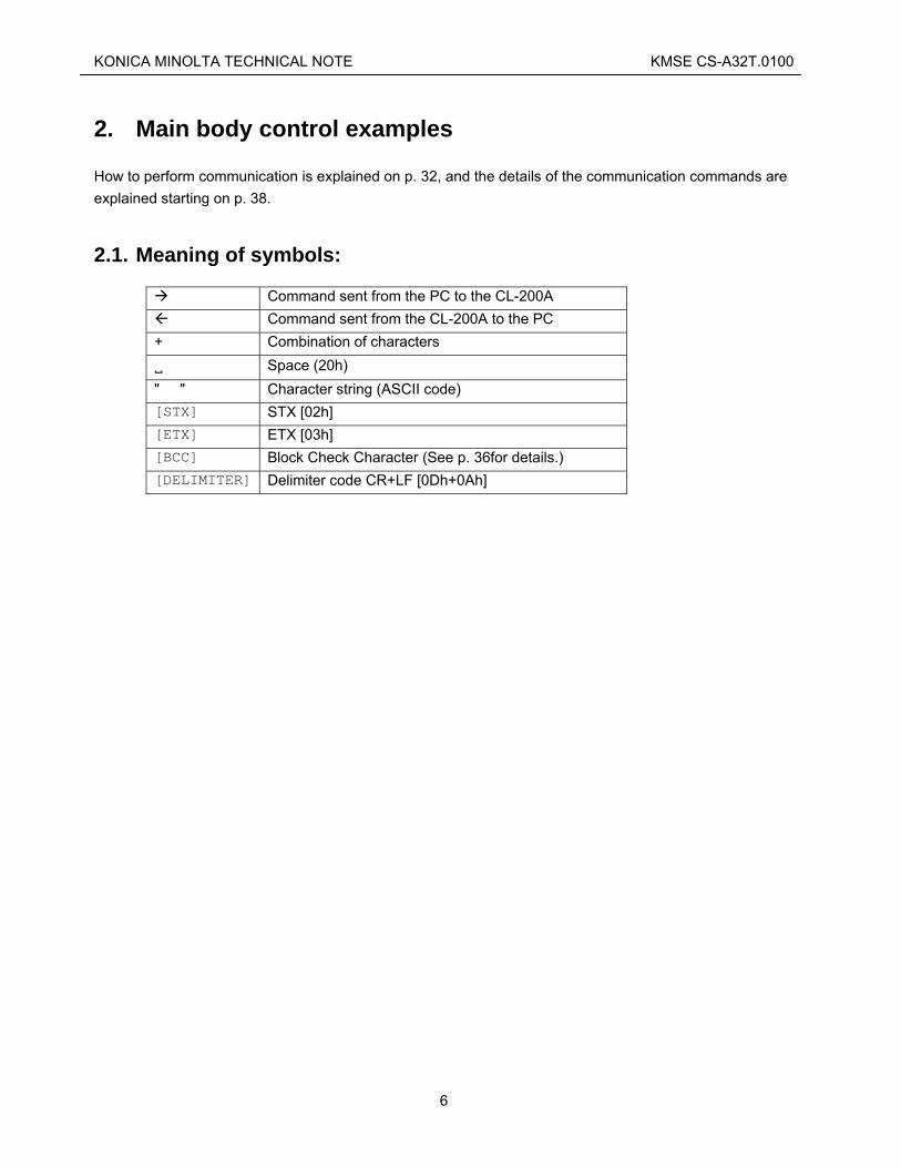
2.1. Meaning of symbols:
Command sent from the PC to the CL-200A Command sent from the CL-200A to the PC
+ Combination of characters Space (20h)
" " Character string (ASCII code) [STX] STX [02h] [ETX] ETX [03h] [BCC] Block Check Character (See p. 36for details.) [DELIMITER] Delimiter code CR+LF [0Dh+0Ah]
6
KONICA MINOLTA TECHNICAL NOTE KMSE CS-A32T.0100
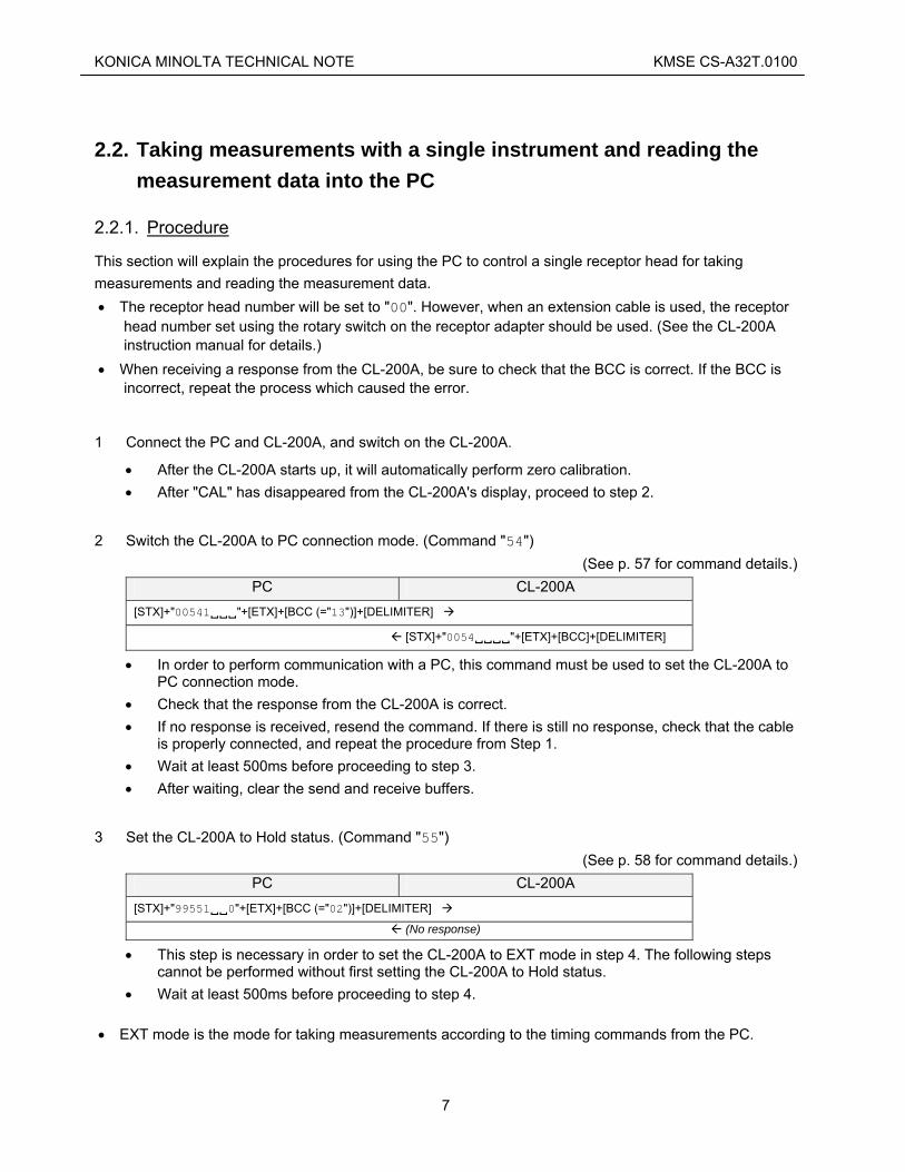
2.2. Taking measurements with a single instrument and reading the measurement data into the PC
2.2.1. Procedure
This section will explain the procedures for using the PC to control a single receptor head for taking measurements and reading the measurement data. • The receptor head number will be set to "00". However, when an extension cable is used, the receptor
head number set using the rotary switch on the receptor adapter should be used. (See the CL-200A instruction manual for details.)
• When receiving a response from the CL-200A, be sure to check that the BCC is correct. If the BCC is incorrect, repeat the process which caused the error.
1 Connect the PC and CL-200A, and switch on the CL-200A.
• After the CL-200A starts up, it will automatically perform zero calibration. • After "CAL" has disappeared from the CL-200A's display, proceed to step 2.
2 Switch the CL-200A to PC connection mode. (Command "54") (See p. 57 for command details.)
PC CL-200A [STX]+"00541 "+[ETX]+[BCC (="13")]+[DELIMITER]
[STX]+"0054 "+[ETX]+[BCC]+[DELIMITER]
• In order to perform communication with a PC, this command must be used to set the CL-200A to PC connection mode.
• Check that the response from the CL-200A is correct. • If no response is received, resend the command. If there is still no response, check that the cable
is properly connected, and repeat the procedure from Step 1. • Wait at least 500ms before proceeding to step 3. • After waiting, clear the send and receive buffers.
3 Set the CL-200A to Hold status. (Command "55") (See p. 58 for command details.)
PC CL-200A [STX]+"99551 0"+[ETX]+[BCC (="02")]+[DELIMITER]
(No response)
• This step is necessary in order to set the CL-200A to EXT mode in step 4. The following steps cannot be performed without first setting the CL-200A to Hold status.
• Wait at least 500ms before proceeding to step 4. • EXT mode is the mode for taking measurements according to the timing commands from the PC.
7

KONICA MINOLTA TECHNICAL NOTE KMSE CS-A32T.0100
4 Set the CL-200A to EXT mode. (Command "40") (See p. 49 for command details.)
PC CL-200A [STX]+"004010 "+[ETX]+[BCC (="06")]+[DELIMITER]
[STX]+"0040 "+[ETX]+[BCC]+[DELIMITER]
• In order to control measurements from the PC, it is necessary to set the CL-200A to EXT mode. • After receiving the response from the CL-200A, check that the ERR byte (indicated by “ " above)
of STATUS is correct. • If an error occurred when setting EXT mode (ERR byte = "4"), step 3 was not completed
correctly. Repeat step 3 and then set EXT mode again. • Depending on the results of the most recent measurement, the following errors may occur.
However, they are not a problem for this step and can be ignored; proceed to the next step. Measurement value over range error (ERR byte = "5") Low luminance error (ERR byte = "6") Outside of range error (ERR byte = "7")
• Wait at least 175ms before proceeding to step 5.
5 Perform measurement. (Command "40") (See p. 49 for command details.)
PC CL-200A [STX]+"994021 "+[ETX]+[BCC (="04")]+[DELIMITER]
(No response)
• A measurement will be taken. • Send this command with the timing at which you want to perform measurements. • Wait at least 500ms before proceeding to step 6.
6 Read the colorimetric measurement value (Example: Read EV, x, y values using the command "02") (See p. 41 for command details.)
PC CL-200A [STX]+"00021200"+[ETX]+[BCC (="02")]+[DELIMITER]
[STX]+"00021 20+32543+38560+40400"+
[ETX]+[BCC]+[DELIMITER]
• The results of the measurement taken in step 5 will be read into the PC. • Measurement data can also be read in other color systems (X, Y, Z; EV, u', v'; EV, Tcp, Δuv), or
multiple commands can be used together to receive measurement results in several color systems can also be performed.
• The PARAMETER (lower 4 digits of the command) can be used to set the calibration mode and/or enable/disable the CF (correction factor) function. In the above example, the calibration mode is set to NORM and the CF function is disabled.
PARAMETER Calibration mode CF function "1200" NORM Disabled "1300" NORM Enabled
8

KONICA MINOLTA TECHNICAL NOTE KMSE CS-A32T.0100
"1201" MULTI Disabled "1301" MULTI Enabled
• When performing measurements with the CF function enabled, since the measurement results will be calculated using the CF set on the CL-200A main body, it is necessary to set the CF values on the main body prior to measurements.
• Changing the calibration mode or CF enabled/disabled setting will cause the measurement results to change. Carefully select the settings according to your measurement purpose.
• After receiving the response from the CL-200A, check that the ERR, RNG, and BA bytes of STATUS are correct.
• Refer to p. 34 for details of the measurement values. • When taking continuous measurements, perform the cycle of steps 5 and 6 repeatedly. • To cancel PC connection mode on the CL-200A, set the CL-200A power switch to OFF.
9

KONICA MINOLTA TECHNICAL NOTE KMSE CS-A32T.0100
2.2.2. Visual Basic 6.0 Program Example
Code Option Explicit
Public strSndCommand As String 'command
Public strRcvCommand As String
Public strSendStr As String 'character
Public strReceiveStr As String
Public strSTX_Command As String 'STX & command
Public strCommand_ETX As String 'command & ETX
Public strCommand_ETX_BCC As String 'command & ETX & BCC
Public intErrNO As Integer 'Error No '0: Normal, 1-7: Error Code, 8: Time Out,
'9:BCC Error, 10:Range Changing, 11:Battery Out Public intErrflg As Integer
Public strData As String 'measurement data Block
Public strData1 As String
Public strData2 As String
Public strData3 As String
Public sngData1 As Single 'measurement data Ev
Public sngData2 As Single 'measurement data x
Public sngData3 As Single 'measurement data y
Public i As Integer 'for LOOP
'*******************************
'*** Starting Measurement ***
'*******************************
Private Sub cmdStartButton_Click()
intErrflg = 0
'------------------------------
'Step 2 PC MODE
'------------------------------
strSndCommand = "00541 "
Call CmdSend(1)
Call ErrCheck
If intErrflg = 1 Then
GoTo SubEnd
End If
'Insert code to wait 500ms here
DoEvents
'------------------------------
'Step 3 HOLD ON
'------------------------------
10

KONICA MINOLTA TECHNICAL NOTE KMSE CS-A32T.0100
strSndCommand = "99551 0"
Call CmdSend(0)
'Insert code to wait 500ms here
DoEvents
'------------------------------
'Step 4 EXT MODE
'------------------------------
strSndCommand = "004010 "
Call CmdSend(1)
Call ErrCheck
If intErrflg = 1 Then
Exit Sub
End If
'Insert code to wait 175ms here
DoEvents
'------------------------------
'Step 5 EXT MEASUREMENT
'------------------------------
strSndCommand = "994021 "
Call CmdSend(0)
'Insert code to wait 500ms here
DoEvents
'------------------------------
'Step 6 READ MEASUREMENT DATA
'------------------------------
strSndCommand = "00021200"
Call CmdSend(1)
Call ErrCheck
If intErrflg = 1 Then
Exit Sub
End If
strData = Right(strRcvCommand, 18)
strData1 = Left(strData, 6)
strData2 = Mid(strData, 7, 6)
strData3 = Right(strData, 6)
'Lv,x,y
sngData1 = Val(Left(strData1, 5)) * 10 ^ (Val(Right(strData1, 1)) - 4)
sngData2 = Val(Left(strData2, 5)) * 10 ^ (Val(Right(strData2, 1)) - 4)
sngData3 = Val(Left(strData3, 5)) * 10 ^ (Val(Right(strData3, 1)) - 4)
End Sub
'*****************************************
'*** Send command & Receive command ***
'*****************************************
Public Sub CmdSend(FlgTimeoutCheck As Integer)
Dim sngStartTime As Single
Dim sngFinishTime As Single
Dim varBuf As String
intErrNO = 0
strRcvCommand = ""
11

KONICA MINOLTA TECHNICAL NOTE KMSE CS-A32T.0100
strReceiveStr = ""
'------------------------------
'Transmission
'------------------------------
Call BCC_Append(strSndCommand)
strSendStr = Chr(2) & strCommand_ETX_BCC & vbCr & vbLf
'Insert code for sending data here
'------------------------------
'Reception & TimeOut Check
'------------------------------
'Insert code to handle data receiving within timeout limit here
'------------------------------
'BCC Check
'------------------------------
strSTX_Command = Left(strReceiveStr, (InStr(1, strReceiveStr, Chr(3)) - 1))
strRcvCommand = Mid(strSTX_Command, 2)
Call BCC_Append(strRcvCommand)
If (strReceiveStr) <> (Chr(2) & strCommand_ETX_BCC & vbCr & vbLf) Then
intErrNO = 9 'BCC Error
Else
intErrNO = 0
End If
End Sub
'**************************
'*** BCC Calculation ***
'**************************
Public Sub BCC_Append(Command As String)
Dim intBCC As Long
Dim strBCC As String
strCommand_ETX = Command & Chr(3)
intBCC = 0
For i = 1 To Len(strCommand_ETX)
intBCC = intBCC Xor Asc(Mid(strCommand_ETX, i, 1))
Next i
strBCC = (Hex(intBCC))
If Len(strBCC) = 1 Then
strBCC = "0" & strBCC
Else
End If
strCommand_ETX_BCC = strCommand_ETX & strBCC
End Sub
12

KONICA MINOLTA TECHNICAL NOTE KMSE CS-A32T.0100
'**********************
'*** Error Check ***
'**********************
Public Sub ErrCheck()
If Mid(strRcvCommand, 8, 1) = "1" Then
intErrNO = 11 'Battery Out
Exit Sub
ElseIf Mid(strRcvCommand, 7, 1) = "6" Then
intErrNO = 10 'Changing Range
Exit Sub
ElseIf intErrNO = 0 Then
If Mid(strRcvCommand, 6, 1) = " " Then
intErrNO = 0
Else
intErrNO = Val(Mid(strRcvCommand, 6, 1))
End If
End If
Select Case intErrNO
Case 0: Exit Sub
Case 1: MsgBox "POWER OF SENSOR WAS OFF.": lblInformation.Caption = "": intErrflg = 1
Case 2: MsgBox "EE-PROM ERROR": lblInformation.Caption = "": intErrflg = 1
Case 3: MsgBox "EE-PROM ERROR": lblInformation.Caption = "": intErrflg = 1
Case 4: MsgBox "EXT ERROR": lblInformation.Caption = "": intErrflg = 1
Case 5: Exit Sub
Case 6: Exit Sub
Case 7: Exit Sub
Case 8: MsgBox "TIME OUT": lblInformation.Caption = "": intErrflg = 1
Case 9: MsgBox "BCC ERROR": lblInformation.Caption = "": intErrflg = 1
Case 10: Exit Sub
Case 11: MsgBox "BATTERY OUT": lblInformation.Caption = "": intErrflg = 1
End Select
End Sub
13

KONICA MINOLTA TECHNICAL NOTE KMSE CS-A32T.0100
2.3. Taking measurements with multiple instruments (receptor heads) and reading the measurement data into the PC
2.3.1. Procedure
• This section will explain the procedures for using the PC to control multiple receptor heads for taking
measurements and reading the measurement data. • Set the receptor head number for each head to different numbers using the rotary switch on each
receptor adapter. Be sure that no duplicate receptor head numbers are set. (See the CL-200A instruction manual for details.)
• When receiving a response from the CL-200A, be sure to check that the BCC is correct. If the BCC is incorrect, repeat the process which caused the error.
1 Connect the PC, CL-200A, and each receptor head, and switch on the CL-200A.
• After the CL-200A starts up, it will automatically perform zero calibration. • After "CAL" has disappeared from the CL-200A's display, proceed to step 2.
• If the connection status of the receptor heads change, the CL-200A power should be switched off
momentarily and then switched back on, and this step repeated again.
2 Switch the CL-200A to PC connection mode. (Command "54") (See p. 57 for command details.)
PC CL-200A [STX]+"00541 "+[ETX]+[BCC (="13")]+[DELIMITER]
[STX]+"0054 "+ [ETX]+[BCC]+[DELIMITER]
• In order to perform communication with a PC, this command must be used to set the CL-200A to PC connection mode.
• Check that the response from the CL-200A is correct. • If no response is received, resend the command. If there is still no response, check that the cable
is properly connected, and repeat the procedure from Step 1. • Wait at least 500ms before proceeding to step 3. • After waiting, clear the send and receive buffers.
3 Set the CL-200A to Hold status. (Command "55") (See p. 58 for command details.)
PC CL-200A [STX]+"99551 0"+[ETX]+[BCC (="02")]+[DELIMITER]
(No response)
• This step is necessary in order to set the CL-200A to EXT mode in step 4. The following steps cannot be performed without first setting the CL-200A to Hold status.
14

KONICA MINOLTA TECHNICAL NOTE KMSE CS-A32T.0100
• Wait at least 500ms before proceeding to step 4. • EXT mode is the mode for taking measurements according to the timing commands from the PC.
4 Set the CL-200A to EXT mode. (Command "40") (See p. 49 for command details.)
PC CL-200A [STX]+"004010 "+[ETX]+[BCC (="06")]+[DELIMITER]
[STX]+"0040 "+[ETX]+[BCC]+[DELIMITER]
[STX]+"014010 "+[ETX]+[BCC (="07")]+[DELIMITER]
[STX]+"0140 "+[ETX]+[BCC]+[DELIMITER]
(Repeat for each receptor head number.) • •
• In order to control measurements from the PC, it is necessary to set the CL-200A to EXT mode. • After receiving the response from the CL-200A, check that the ERR byte (indicated by " " above)
of STATUS is correct. • If an error occurred when setting EXT mode (ERR byte = "4"), step 3 was not completed
correctly. Repeat step 3 and then set EXT mode again. • Depending on the results of the most recent measurement, the following errors may occur.
However, they are not a problem for this step and can be ignored; proceed to the next step. Measurement value over range error (ERR byte = "5") Low luminance error (ERR byte = "6") Outside of range error (ERR byte = "7")
• Wait at least 175ms before proceeding to step 5.
5 Perform measurement. (Command "40") (See p. 49 for command details.)
PC CL-200A [STX]+"994021 "+[ETX]+[BCC (="04")]+[DELIMITER]
(No response)
• A measurement will be taken. • Send this command with the timing at which you want to perform measurements. • Wait at least 500ms before proceeding to step 6.
6 Read the colorimetric measurement values (Example: Read EV, x, y values using the command "02") (See p. 41 for command details.)
PC CL-200A [STX]+"00021200"+[ETX]+[BCC (="02")]+[DELIMITER]
[STX]+"00021 20+32543+38560+40400"+
[ETX]+[BCC]+[DELIMITER]
15

KONICA MINOLTA TECHNICAL NOTE KMSE CS-A32T.0100
[STX]+"01021200"+[ETX]+[BCC (="03")]+[DELIMITER]
[STX]+"01021 20+32543+38560+40400"+
[ETX]+[BCC]+[DELIMITER]
(Repeat for each receptor head number.) • •
• The results of the measurement taken in step 5 will be read into the PC. • Measurement data can also be read in other color systems (X, Y, Z; EV, u', v'; EV, Tcp, Δuv), or
multiple commands can be used together to receive measurement results in several color systems can also be performed.
• The PARAMETER (lower 4 digits of the command) can be used to set the calibration mode and/or enable/disable the CF (correction factor) function. In the above example, the calibration mode is set to NORM and the CF function is disabled.
PARAMETER Calibration mode CF function "1200" NORM Disabled "1300" NORM Enabled "1201" MULTI Disabled "1301" MULTI Enabled
• When performing measurements with the CF function enabled, since the measurement results will be calculated using the CF set on the CL-200A main body, it is necessary to set the CF values on the main body prior to measurements.
• Changing the calibration mode or CF enabled/disabled setting will cause the measurement results to change. Carefully select the settings according to your measurement purpose.
• After receiving the response from the CL-200A, check that the ERR, RNG, and BA bytes of STATUS is correct.
• Refer to p. 34 for details of the measurement values. • When taking continuous measurements, perform the cycle of steps 5 and 6 repeatedly. • To cancel PC connection mode on the CL-200A, set the CL-200A power switch to OFF.
16

KONICA MINOLTA TECHNICAL NOTE KMSE CS-A32T.0100
2.3.2. Visual Basic 6.0 Program Example
Code Option Explicit
Public strSndCommand As String 'command
Public strRcvCommand As String
Public strSendStr As String 'character
Public strReceiveStr As String
Public strSTX_Command As String 'STX & command
Public strCommand_ETX As String 'command & ETX
Public strCommand_ETX_BCC As String 'command & ETX & BCC
Public intErrNO As Integer 'Error No
'0: Normal, 1-7: Error Code, 8: Time Out, 9:BCC
'Error, 10: Range Changing, 11: Battery Out
Public intErrflg As Integer
Public strData As String 'measurement data Block
Public strData1 As String
Public strData2 As String
Public strData3 As String
Public sngData1 As Single 'measurement data Ev
Public sngData2 As Single 'measurement data x
Public sngData3 As Single 'measurement data y
Public SensorNo
Public m As Integer 'number of sensor
Public n As Integer
Public i As Integer 'for LOOP
Public j As Integer 'for LOOP
'*******************************
'*** Starting Measurement ***
'*******************************
Private Sub cmdStartButton_Click()
intErrflg = 0
'------------------------------
'Step 2 PC MODE
'------------------------------
j = 0
strSndCommand = "00541 "
Call CmdSend(1)
Call ErrCheck
If intErrflg = 1 Then
Exit Sub
17

KONICA MINOLTA TECHNICAL NOTE KMSE CS-A32T.0100
End If
'Insert code to wait 500ms here
DoEvents
'------------------------------
'Step 3 HOLD ON
'------------------------------
strSndCommand = "99551 0"
Call CmdSend(0)
'Insert code to wait 500ms here
DoEvents
'------------------------------
'Step 4 EXT MODE
'------------------------------
For j = 0 To n
strSndCommand = SensorNo(j) & "4010 "
Call CmdSend(1)
Call ErrCheck
If intErrflg = 1 Then
Exit Sub
End If
DoEvents
Next j
'Insert code to wait 175ms here
'------------------------------
'Step 5 EXT MEASUREMENT
'------------------------------
strSndCommand = "994021 "
Call CmdSend(0)
'Insert code to wait 500ms here
DoEvents
'------------------------------
'Step 6 READ MEASUREMENT DATA
'------------------------------
For j = 0 To n
strSndCommand = SensorNo(j) & "021200"
Call CmdSend(1)
Call ErrCheck
If intErrflg = 1 Then
Exit Sub
End If
strData = Right(strRcvCommand, 18)
strData1 = Left(strData, 6)
strData2 = Mid(strData, 7, 6)
strData3 = Right(strData, 6)
'Lv,x,y
sngData1 = Val(Left(strData1, 5)) * 10 ^ (Val(Right(strData1, 1)) - 4)
sngData2 = Val(Left(strData2, 5)) * 10 ^ (Val(Right(strData2, 1)) - 4)
sngData3 = Val(Left(strData3, 5)) * 10 ^ (Val(Right(strData3, 1)) - 4)
'Data obtained from the receptor heads are then used.
DoEvents
Next j
18

KONICA MINOLTA TECHNICAL NOTE KMSE CS-A32T.0100
End Sub
'*****************************************
'*** Send command & Receive command ***
'*****************************************
Public Sub CmdSend(FlgTimeoutCheck As Integer)
Dim sngStartTime As Single
Dim sngFinishTime As Single
Dim varBuf As String
intErrNO = 0
strRcvCommand = ""
strReceiveStr = ""
'-------------------------
'Transmission
'-------------------------
Call BCC_Append(strSndCommand)
strSendStr = Chr(2) & strCommand_ETX_BCC & vbCr & vbLf
'Insert code for sending data here
'-------------------------
'Reception & TimeOut Check
'-------------------------
'Insert code to handle data receiving within timeout limit here
'-------------------------
'BCC Check
'-------------------------
strSTX_Command = Left(strReceiveStr, (InStr(1, strReceiveStr, Chr(3)) - 1))
strRcvCommand = Mid(strSTX_Command, 2)
Call BCC_Append(strRcvCommand)
If (strReceiveStr) <> (Chr(2) & strCommand_ETX_BCC & vbCr & vbLf) Then
intErrNO = 9 'BCC Error
Else
intErrNO = 0
End If
End Sub
'**************************
'*** BCC Calculation ***
'**************************
Public Sub BCC_Append(Command As String)
Dim intBCC As Long
Dim strBCC As String
strCommand_ETX = Command & Chr(3)
intBCC = 0
For i = 1 To Len(strCommand_ETX)
19
KONICA MINOLTA TECHNICAL NOTE KMSE CS-A32T.0100
intBCC = intBCC Xor Asc(Mid(strCommand_ETX, i, 1))
Next i
strBCC = (Hex(intBCC))
If Len(strBCC) = 1 Then
strBCC = "0" & strBCC
Else
End If
strCommand_ETX_BCC = strCommand_ETX & strBCC
End Sub
'**********************
'*** Error Check ***
'**********************
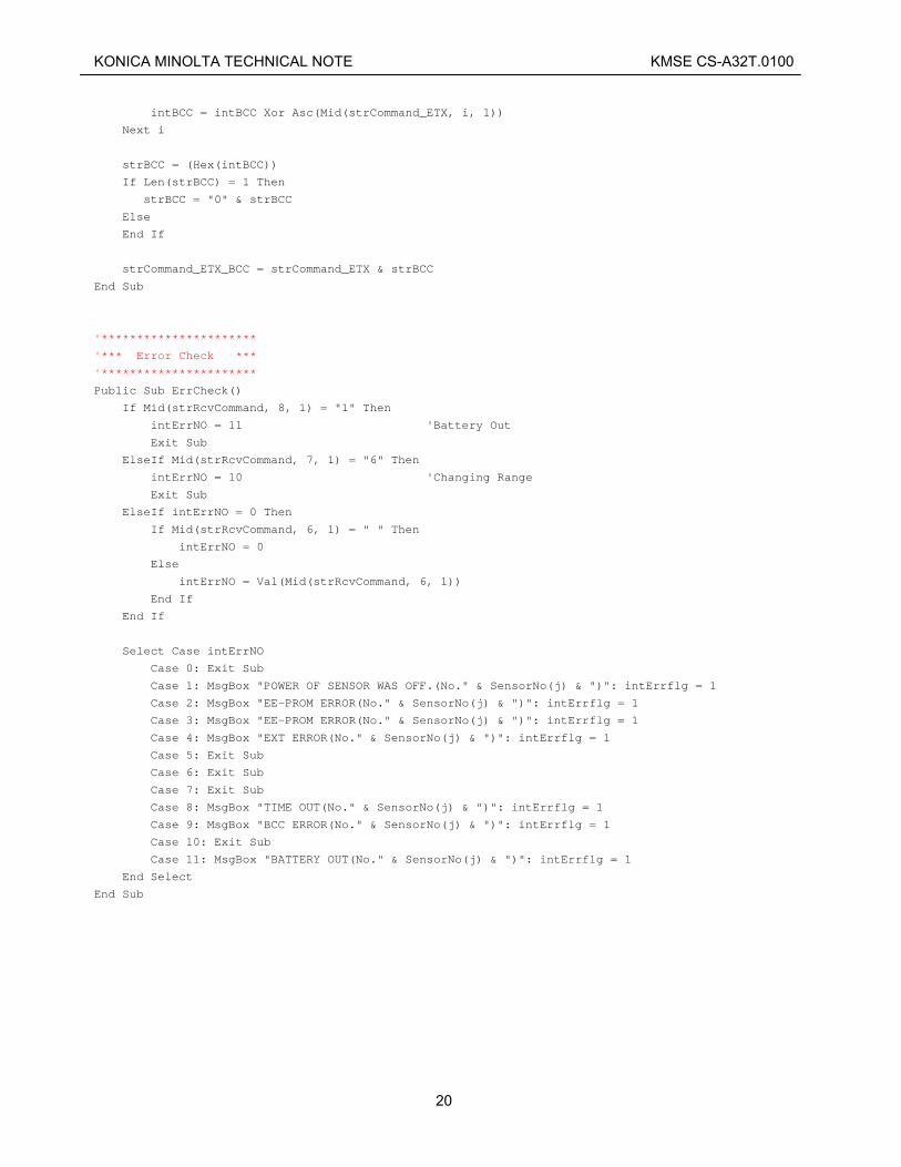
Public Sub ErrCheck()
If Mid(strRcvCommand, 8, 1) = "1" Then
intErrNO = 11 'Battery Out
Exit Sub
ElseIf Mid(strRcvCommand, 7, 1) = "6" Then
intErrNO = 10 'Changing Range
Exit Sub
ElseIf intErrNO = 0 Then
If Mid(strRcvCommand, 6, 1) = " " Then
intErrNO = 0
Else
intErrNO = Val(Mid(strRcvCommand, 6, 1))
End If
End If
Select Case intErrNO
Case 0: Exit Sub
Case 1: MsgBox "POWER OF SENSOR WAS OFF.(No." & SensorNo(j) & ")": intErrflg = 1
Case 2: MsgBox "EE-PROM ERROR(No." & SensorNo(j) & ")": intErrflg = 1
Case 3: MsgBox "EE-PROM ERROR(No." & SensorNo(j) & ")": intErrflg = 1
Case 4: MsgBox "EXT ERROR(No." & SensorNo(j) & ")": intErrflg = 1
Case 5: Exit Sub
Case 6: Exit Sub
Case 7: Exit Sub
Case 8: MsgBox "TIME OUT(No." & SensorNo(j) & ")": intErrflg = 1
Case 9: MsgBox "BCC ERROR(No." & SensorNo(j) & ")": intErrflg = 1
Case 10: Exit Sub
Case 11: MsgBox "BATTERY OUT(No." & SensorNo(j) & ")": intErrflg = 1
End Select
End Sub
20

KONICA MINOLTA TECHNICAL NOTE KMSE CS-A32T.0100
2.4. Performing user calibration with a single instrument
2.4.1. Procedure
This section will explain the procedures for using the PC to control a single receptor head for taking measurements and reading the measurement data. • The receptor head number will be set to "00". However, when an extension cable is used, the receptor
head number set using the rotary switch on the receptor adapter should be used. (See the CL-200A instruction manual for details.)
• When receiving a response from the CL-200A, be sure to check that the BCC is correct. If the BCC is incorrect, repeat the process which caused the error.
1 Connect the PC and CL-200A, and switch on the CL-200A.
• After the CL-200A starts up, it will automatically perform zero calibration. • After "CAL" has disappeared from the CL-200A's display, proceed to step 2.
2 Switch the CL-200A to PC connection mode. (Command "54") (See p. 57 for command details.)
PC CL-200A [STX]+"00541 "+[ETX]+[BCC (="13")]+[DELIMITER]
[STX]+"0054 "+[ETX]+[BCC]+[DELIMITER]
• In order to perform communication with a PC, this command must be used to set the CL-200A to PC connection mode.
• Check that the response from the CL-200A is correct. • If no response is received, resend the command. If there is still no response, check that the cable
is properly connected, and repeat the procedure from Step 1. • Wait at least 500ms before proceeding to step 3. • After waiting, clear the send and receive buffers.
3 Set the CL-200A to Hold status. (Command "55") (See p. 58 for command details.)
PC CL-200A [STX]+"99551 0"+[ETX]+[BCC (="02")]+[DELIMITER]
(No response)
• This step is necessary in order to set the CL-200A to EXT mode in step 4. The following steps cannot be performed without first setting the CL-200A to Hold status.
• Wait at least 500ms before proceeding to step 4. • EXT mode is the mode for taking measurements according to the timing commands from the PC.
4 Set the CL-200A to EXT mode. (Command "40")
21

KONICA MINOLTA TECHNICAL NOTE KMSE CS-A32T.0100
(See p. 49 for command details.) PC CL-200A
[STX]+"004010 "+[ETX]+[BCC (="06")]+[DELIMITER]
[STX]+"0040 "+[ETX]+[BCC]+[DELIMITER]
• In order to control measurements from the PC, it is necessary to set the CL-200A to EXT mode. • After receiving the response from the CL-200A, check that the ERR byte (indicated by “ " above)
of STATUS is correct. • If an error occurred when setting EXT mode (ERR byte = "4"), step 3 was not completed
correctly. Repeat step 3 and then set EXT mode again. • Depending on the results of the most recent measurement, the following errors may occur.
However, they are not a problem for this step and can be ignored; proceed to the next step. Measurement value over range error (ERR byte = "5") Low luminance error (ERR byte = "6") Outside of range error (ERR byte = "7")
• Wait at least 175ms before proceeding to step 5.
5 Perform measurement. (Command "40") (See p. 49 for command details.)
PC CL-200A [STX]+"994021 "+[ETX]+[BCC (="04")]+[DELIMITER]
(No response)
• A measurement will be taken. • Send this command with the timing at which you want to perform measurements. • Wait at least 500ms before proceeding to step 6.
6 Read the colorimetric measurement value (Example: Read X2, Y, Z values using the command "45") (See p. 51 for command details.)
PC CL-200A [STX]+"00451000"+[ETX]+[BCC (="03")]+[DELIMITER]
[STX]+"00451 20+4417D747442DD82943B3C6C2
"+ [ETX]+[BCC]+[DELIMITER]
• The results of the measurement taken in step 5 will be read into the PC. • After receiving the response from the CL-200A, check that the ERR, RNG, and BA bytes of
STATUS are correct. • Refer to p. 34 for details of the measurement values.
7 Determine the calibration coefficients.
22

KONICA MINOLTA TECHNICAL NOTE KMSE CS-A32T.0100
7-1 Obtain the X2YZ values. Obtain the X2YZ values from the values measured in Step 6:
⎪⎩
⎪⎨
⎧
===
ZmesZYmesYXmesX
)()()( 22
7-2 Determine the calibration values (EVxy) to be adjusted to. Use the following conversion equations to determine the X2YZ values from the luminance EV and chromaticity xy calibration values:
⎪⎪
⎩
⎪⎪
⎨
⎧
∗−−=
=
∗−∗+∗=
yEvyxstdZ
EvstdYy
EvyxstdX
)1()(
)(
)1672.01672.01672.1()(2
7-3 Calculate the user calibration coefficients. Calculate the user calibration coefficients from the results of Steps 7-1 and 7-2 above according to the following equations:
⎪⎪⎪
⎩
⎪⎪⎪
⎨
⎧
=
=
=
)()()()(
)()(
2
2
mesZstdZmesYstdYmesXstdX
γ
β
α
8 Write the calibration coefficients to the instrument (Command "48") (See p. 55 for command details.)
PC CL-200A [STX]+"004811 "+”3F800000000000003E2B
367A”+[ETX]+[BCC (="07")]+[DELIMITER]
[STX]+"0048 "+[ETX]+[BCC]+[DELIMITER]
[STX]+"004821 "+”000000003F8000000000
0000”+[ETX]+[BCC (="71")]+[DELIMITER]
[STX]+"0048 "+[ETX]+[BCC]+[DELIMITER]
[STX]+"004831 "+”00000000000000003F80
0000”+[ETX]+[BCC (="70")]+[DELIMITER]
[STX]+"0048 "+[ETX]+[BCC]+[DELIMITER]
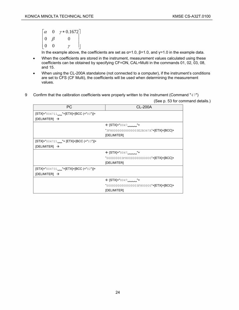
• The coefficients calculated in Step 7 are used in the following matrix, which is sent in 3 lines to the instrument.
23
KONICA MINOLTA TECHNICAL NOTE KMSE CS-A32T.0100
⎥⎥⎥
⎦
⎤
⎢⎢⎢
⎣
⎡ ∗
γβ
γα
00001672.00
In the example above, the coefficients are set as α=1.0, β=1.0, and γ=1.0 in the example data. • When the coefficients are stored in the instrument, measurement values calculated using these
coefficients can be obtained by specifying CF=ON, CAL=Multi in the commands 01, 02, 03, 08, and 15.
• When using the CL-200A standalone (not connected to a computer), if the instrument’s conditions are set to CFS (CF Multi), the coefficients will be used when determining the measurement values.
9 Confirm that the calibration coefficients were properly written to the instrument (Command "47") (See p. 53 for command details.)
PC CL-200A [STX]+"004711 "+[ETX]+[BCC (="00")]+
[DELIMITER]
[STX]+"0047 "+
”3F800000000000003E2B367A”+[ETX]+[BCC]+ [DELIMITER]
[STX]+"004721 "+ [ETX]+[BCC (="03")]+
[DELIMITER]
[STX]+"0047 "+
”000000003F80000000000000”+[ETX]+[BCC]+ [DELIMITER]
[STX]+"004731 "+[ETX]+[BCC (="02")]+
[DELIMITER]
[STX]+"0047 "+
”00000000000000003F800000”+[ETX]+[BCC]+ [DELIMITER]
24

KONICA MINOLTA TECHNICAL NOTE KMSE CS-A32T.0100
2.4.2. Visual Basic 6.0 Program Example
Code
Option Explicit
Public strSndCommand As String 'command
Public strRcvCommand As String
Public strSendStr As String 'character
Public strReceiveStr As String
Public strSTX_Command As String 'STX & command
Public strCommand_ETX As String 'command & ETX
Public strCommand_ETX_BCC As String 'command & ETX & BCC
Public intErrNO As Integer 'Error No
'0:Normal, 1-7:Error Code, 8:Time Out, 9:BCC Error
'10:Range Changing, 11:Battery Out
Public intErrflg As Integer
Public strData As String 'measurement data Block
Public strData1 As String
Public strData2 As String
Public strData3 As String
Public sngData1 As Single 'measurement data Ev
Public sngData2 As Single 'measurement data x
Public sngData3 As Single 'measurement data y
Public i As Integer 'for LOOP
Public j As Integer 'for LOOP
Private Type tagData
Bytedata(3) As Byte
End Type
Private Type tagSngData
SngData As Single
End Type
'******************************************
'*** Starting Calibration ***
'******************************************
Private Sub cmdCalButton_Click()
Dim X2YZ_mes(2) As Single
Dim X2YZ_std(2) As Single
Dim Evxy_std(2) As Single
Dim cfc(2) As Single
Dim StrSendString(2) As String
25
KONICA MINOLTA TECHNICAL NOTE KMSE CS-A32T.0100
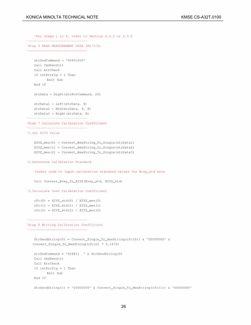
'For steps 1 to 5, refer to Section 2.2.2 or 2.3.2
'------------------------------
'Step 6 READ MEASUREMENT DATA (X2/Y/Z)
'------------------------------
strSndCommand = "00451000"
Call CmdSend(1)
Call ErrCheck
If intErrflg = 1 Then
Exit Sub
End If
strData = Right(strRcvCommand, 24)
strData1 = Left(strData, 8)
strData2 = Mid(strData, 9, 8)
strData3 = Right(strData, 8)
'------------------------------
'Step 7 Calculate Calibration Coefficient
'------------------------------
'1,Get X2YZ Value
X2YZ_mes(0) = Convert_HexString_To_Single(strData1)
X2YZ_mes(1) = Convert_HexString_To_Single(strData2)
X2YZ_mes(2) = Convert_HexString_To_Single(strData3)
'2,Determine Calibration Standard
'Insert code to input calibration standard values for Evxy_std here
Call Convert_Evxy_To_X2YZ(Evxy_std, X2YZ_std)
'3,Calculate User Calibration Coefficient
cfc(0) = X2YZ_std(0) / X2YZ_mes(0)
cfc(1) = X2YZ_std(1) / X2YZ_mes(1)
cfc(2) = X2YZ_std(2) / X2YZ_mes(2)
'------------------------------
'Step 8 Writing Calibration Coefficient
'------------------------------
StrSendString(0) = Convert_Single_To_HexString(cfc(0)) & "00000000" &
Convert_Single_To_HexString(cfc(2) * 0.1672)
strSndCommand = "004811 " & StrSendString(0)
Call CmdSend(1)
Call ErrCheck
If intErrflg = 1 Then
Exit Sub
End If
StrSendString(1) = "00000000" & Convert_Single_To_HexString(cfc(1)) & "00000000"
26

KONICA MINOLTA TECHNICAL NOTE KMSE CS-A32T.0100
strSndCommand = "004821 " & StrSendString(1)
Call CmdSend(1)
Call ErrCheck
If intErrflg = 1 Then
Exit Sub
End If
StrSendString(2) = "00000000" & "00000000" & Convert_Single_To_HexString(cfc(2))
strSndCommand = "004831 " & StrSendString(2)
Call CmdSend(1)
Call ErrCheck
If intErrflg = 1 Then
Exit Sub
End If
'------------------------------
'Step 9 Check Calibration Coefficient
'------------------------------
strSndCommand = "004711 "
Call CmdSend(1)
Call ErrCheck
If intErrflg = 1 Then
Exit Sub
End If
strData = Right(strRcvCommand, 24)
If (StrComp(strData, StrSendString(0)) <> 0) Then
lblInformation.Caption = "Calibration NG"
Exit Sub
End If
strSndCommand = "004721 "
Call CmdSend(1)
Call ErrCheck
If intErrflg = 1 Then
Exit Sub
End If
strData = Right(strRcvCommand, 24)
If (StrComp(strData, StrSendString(1)) <> 0) Then
lblInformation.Caption = "Calibration NG"
Exit Sub
End If
strSndCommand = "004731 "
Call CmdSend(1)
Call ErrCheck
If intErrflg = 1 Then
Exit Sub
End If
strData = Right(strRcvCommand, 24)
If (StrComp(strData, StrSendString(2)) <> 0) Then
27

KONICA MINOLTA TECHNICAL NOTE KMSE CS-A32T.0100
lblInformation.Caption = "Calibration NG"
Exit Sub
End If
lblInformation.Caption = "Calibration OK"
End Sub
'******************************************
'*** Convert Evxy To X2YZ ***
'******************************************
Public Sub Convert_Evxy_To_X2YZ(Evxy() As Single, X2YZ() As Single)
X2YZ(0) = ((1.1672 * Evxy(1) + 0.1672 * Evxy(2) - 0.1672) * Evxy(0)) / Evxy(2)
X2YZ(1) = Evxy(0)
X2YZ(2) = ((1 - Evxy(1) - Evxy(2)) * Evxy(0)) / Evxy(2)
End Sub
'******************************************
'*** Convert HexString To Single ***
'******************************************
Public Function Convert_HexString_To_Single(HexString As String) As Single
Dim TmpData As tagData
Dim TmpSngData As tagSngData
For i = 0 To 3
TmpData.Bytedata(3 - i) = Val("&H" & Mid(HexString, 1 + 2 * i, 2))
Next i
LSet TmpSngData = TmpData
Convert_HexString_To_Single = TmpSngData.SngData
End Function
'******************************************
'*** Convert Single To HexString ***
'******************************************
Public Function Convert_Single_To_HexString(SingleData As Single) As String
Dim TmpData As tagData
Dim TmpSngData As tagSngData
TmpSngData.SngData = SingleData
LSet TmpData = TmpSngData
For i = 0 To 3
If (Len(Hex(TmpData.Bytedata(3 - i))) = 1) Then
Convert_Single_To_HexString = Convert_Single_To_HexString & "0"
End If
Convert_Single_To_HexString = Convert_Single_To_HexString & (Hex(TmpData.Bytedata(3 -
i)))
28

KONICA MINOLTA TECHNICAL NOTE KMSE CS-A32T.0100
Next i
End Function
'******************************************
'*** Send command & Receive command ***
'******************************************
Public Sub CmdSend(FlgTimeoutCheck As Integer)
Dim sngStartTime As Single
Dim sngFinishTime As Single
Dim varBuf As String
intErrNO = 0
strRcvCommand = ""
strReceiveStr = ""
'------------------------------
'Transmission
'------------------------------
Call BCC_Append(strSndCommand)
strSendStr = Chr(2) & strCommand_ETX_BCC & vbCr & vbLf
'Insert code for sending data here
'------------------------------
'Reception & TimeOut Check
'------------------------------
'Insert code to handle data receiving within timeout limit here
'------------------------------
'BCC Check
'------------------------------
strSTX_Command = Left(strReceiveStr, (InStr(1, strReceiveStr, Chr(3)) - 1))
strRcvCommand = Mid(strSTX_Command, 2)
Call BCC_Append(strRcvCommand)
If (strReceiveStr) <> (Chr(2) & strCommand_ETX_BCC & vbCr & vbLf) Then
intErrNO = 9 'BCC Error
Else
intErrNO = 0
End If
End Sub
'***************************
'*** BCC Calculation ***
'***************************
Public Sub BCC_Append(Command As String)
Dim intBCC As Long
Dim strBCC As String
strCommand_ETX = Command & Chr(3)
intBCC = 0
For i = 1 To Len(strCommand_ETX)
29

KONICA MINOLTA TECHNICAL NOTE KMSE CS-A32T.0100
intBCC = intBCC Xor Asc(Mid(strCommand_ETX, i, 1))
Next i
strBCC = (Hex(intBCC))
If Len(strBCC) = 1 Then
strBCC = "0" & strBCC
Else
End If
strCommand_ETX_BCC = strCommand_ETX & strBCC
End Sub
'***********************
'*** Error Check ***
'***********************
Public Sub ErrCheck()
If Mid(strRcvCommand, 8, 1) = "1" Then
intErrNO = 11 'Battery Out
Exit Sub
ElseIf Mid(strRcvCommand, 7, 1) = "6" Then
intErrNO = 10 'Changing Range
Exit Sub
ElseIf intErrNO = 0 Then
If Mid(strRcvCommand, 6, 1) = " " Then
intErrNO = 0
Else
intErrNO = Val(Mid(strRcvCommand, 6, 1))
End If
End If
Select Case intErrNO
Case 0: Exit Sub
Case 1: MsgBox "POWER OF SENSOR WAS OFF.": lblInformation.Caption = "": intErrflg = 1
Case 2: MsgBox "EE-PROM ERROR": lblInformation.Caption = "": intErrflg = 1
Case 3: MsgBox "EE-PROM ERROR": lblInformation.Caption = "": intErrflg = 1
Case 4: MsgBox "EXT ERROR": lblInformation.Caption = "": intErrflg = 1
Case 5: Exit Sub
Case 6: Exit Sub
Case 7: Exit Sub
Case 8: MsgBox "TIME OUT": lblInformation.Caption = "": intErrflg = 1
Case 9: MsgBox "BCC ERROR": lblInformation.Caption = "": intErrflg = 1
Case 10: Exit Sub
Case 11: MsgBox "BATTERY OUT": lblInformation.Caption = "": intErrflg = 1
End Select
End Sub
'Note: When using .NET, the above functions Convert_HexString_To_Single and
Convert_Single_To_HexString cannot be used without modification. Refer to the following code and
make modifications as necessary.
'******************************************
'*** Convert HexString To Single ***
'******************************************
30

KONICA MINOLTA TECHNICAL NOTE KMSE CS-A32T.0100
Public Function Convert_HexString_To_Single(ByVal StringData As String) As Single
Dim bytedata(3) As Byte
Dim i As Integer
For i = 0 To 3
bytedata(3 - i) = Val("&H" & Mid(StringData, 1 + 2 * i, 2))
Next i
Convert_HexString_To_Single = BitConverter.ToSingle(bytedata, 0)
End Function
'******************************************
'*** Convert Single To HexString ***
'******************************************
Public Function Convert_Single_To_HexString(ByVal SingledData As Single) As String
Dim bytedata(3) As Byte
Dim i As Integer
bytedata = BitConverter.GetBytes(SingledData)
For i = 0 To 3
If (Len(Hex(bytedata(3 - i))) = 1) Then
Convert_Single_To_HexString = Convert_Single_To_HexString & "0"
End If
Convert_Single_To_HexString = Convert_Single_To_HexString & (Hex(bytedata(3 - i)))
Next i
End Function
31

KONICA MINOLTA TECHNICAL NOTE KMSE CS-A32T.0100
3. Reference
3.1. Communication method
• The communication parameters for the CL-200A are as shown in the table below. Set the PC to these parameters.
Parameter Details Communication method Start/stop synchronization; Half duplex Baud rate 9600bps (fixed) Character length 7 bits Parity Even Stop bits 1 bit Delimiter code CR+LF
• Commands from the PC to the CL-200A and command responses from the CL-200A are fixed-length
strings (ASCII code). • Half-duplex communication is used. Because of this, when sending a series of commands, it is
necessary to receive the command response (including the delimiter code) from the instrument for each command and wait the specified length of time before sending the next command. However, certain commands do not provide a command response.
• For connecting the CL-200A with a PC, use the exclusive Communication Cable T-A15 (sold separately).
32
KONICA MINOLTA TECHNICAL NOTE KMSE CS-A32T.0100
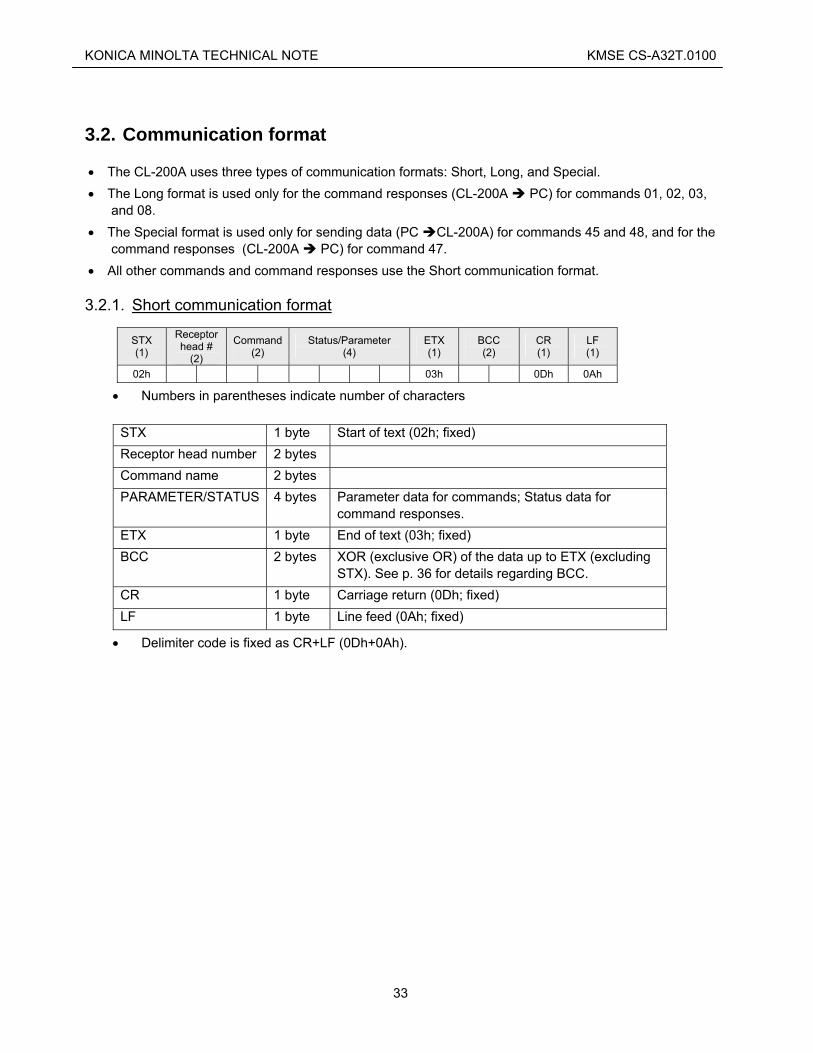
3.2. Communication format
• The CL-200A uses three types of communication formats: Short, Long, and Special. • The Long format is used only for the command responses (CL-200A PC) for commands 01, 02, 03,
and 08. • The Special format is used only for sending data (PC CL-200A) for commands 45 and 48, and for the
command responses (CL-200A PC) for command 47. • All other commands and command responses use the Short communication format.
3.2.1. Short communication format
STX (1)
Receptor head #
(2)
Command (2)
Status/Parameter (4)
ETX (1)
BCC (2)
CR (1)
LF (1)
02h 03h 0Dh 0Ah
• Numbers in parentheses indicate number of characters
STX 1 byte Start of text (02h; fixed) Receptor head number 2 bytes Command name 2 bytes PARAMETER/STATUS 4 bytes Parameter data for commands; Status data for
command responses. ETX 1 byte End of text (03h; fixed) BCC 2 bytes XOR (exclusive OR) of the data up to ETX (excluding
STX). See p. 36 for details regarding BCC. CR 1 byte Carriage return (0Dh; fixed) LF 1 byte Line feed (0Ah; fixed)
• Delimiter code is fixed as CR+LF (0Dh+0Ah).
33

KONICA MINOLTA TECHNICAL NOTE KMSE CS-A32T.0100
3.2.2. Long communication format
• The Long format is the same as the Short format, with the addition of Data bytes. • Details of items other than Data are the same as those for the Short format. • Data is used in determining the BCC. • Data contains the measurement values (6 columns × 3 values) in the format shown below: STX (1)
Receptor head # (2)
Command (2)
Status (4)
Data (6 × 3 blocks)
ETX (1)
BCC (2)
CR (1)
LF (1)
02h 03h 0Dh 0Ah
1 block of data Repeated for remaining 2 blocks. Sign Value Value Value Value Exp.
The meaning of each parameter for Data is shown below.
• Sign
Character "+" (2Bh) "-" (2Dh) "=" (3Dh)Meaning + - ±
• Numerical values: 4 significant digits
• Exponent
Character "0" "1" "2" "3" "4" "5" "6" "7" "8" "9" Meaning 10-4 10-3 10-2 10-1 100 101 102 103 104 105
Measurement value examples 0.001
"+" "0" "0" "0" "1" "1"
-0.0001 "-" "0" "0" "0" "1" "0"
123
"+" "1" "2" "3" "4"
±0 "=" "0" "0"
9876×103
"+" "9" "8" "7" "6" "7"
indicates a space (20h).
34
KONICA MINOLTA TECHNICAL NOTE KMSE CS-A32T.0100
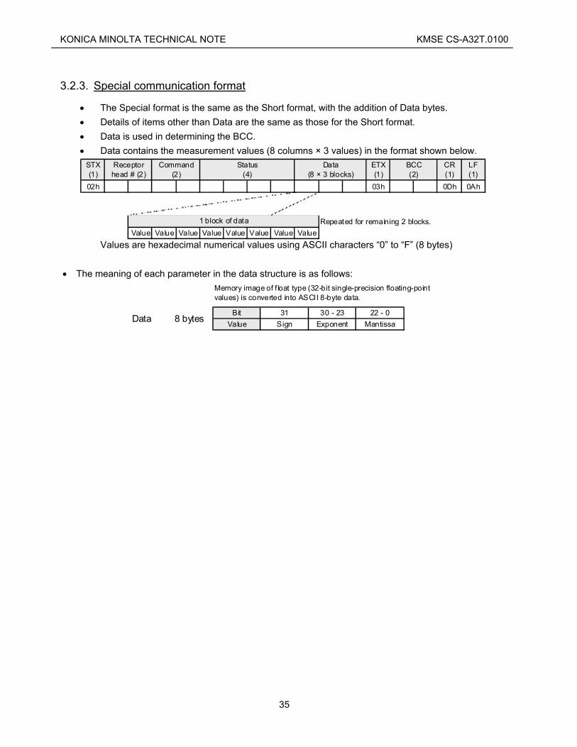
3.2.3. Special communication format
• The Special format is the same as the Short format, with the addition of Data bytes. • Details of items other than Data are the same as those for the Short format. • Data is used in determining the BCC. • Data contains the measurement values (8 columns × 3 values) in the format shown below.
STX(1)
ETX(1)
CR(1)
LF(1)
02h 03h 0Dh 0Ah
Value Value Value Value Value Value Value ValueRepeated for remaining 2 blocks.
BCC(2)
Data(8 × 3 blocks)
Receptorhead # (2)
Command(2)
Status(4)
1 block of data
Values are hexadecimal numerical values using ASCII characters “0” to “F” (8 bytes)
• The meaning of each parameter in the data structure is as follows:
Bit 31 30 - 23 22 - 0Value Sign Exponent MantissaData 8 bytes
Memory image of f loat type (32-bit single-precision floating-pointvalues) is converted into ASCII 8-byte data.
35

KONICA MINOLTA TECHNICAL NOTE KMSE CS-A32T.0100
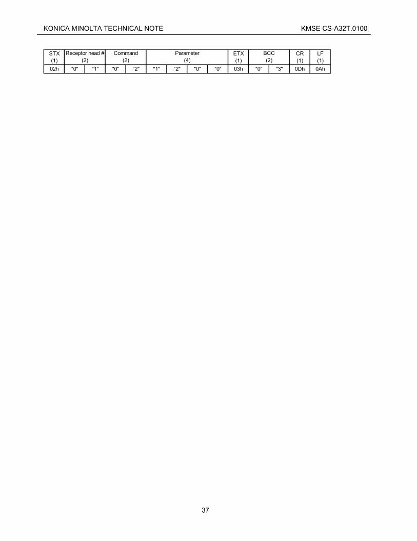
3.2.4. BCC
The BCC (Block Check Character) of the CL-200A is obtained by successively XORing (taking the exclusive OR of) the message bytes starting from the first Head No. byte and ending with the final data byte (everything between STX and ETX, excluding STX and ETX), with the result expressed as a 2-byte ASCII value. The BCC can be checked to verify the reliability of the communication data. When sending a command from the PC to the CL-200A, be sure to set the BCC correctly. If the BCC is set incorrectly, the CL-200A will not respond. When receiving data from, the CL-200A, the BCC should be checked, and if the value is incorrect, the response from the instrument is invalid and is not reliable.
About "Exclusive OR": Exclusive OR is a boolean logic operation in which the result is 0 if the 2 bits are the same, and 1 if they are different. So, for example,
0 and 0 would be 0 1 and 0 would be 1 1 and 1 would be 0
BCC setting example For this example, the following command will be sent: Command 02 (read colorimetric measurement values) is being sent to receptor head 01. CF function is disabled, and calibration mode is set to NORM.
STX (1)
ETX (1)
CR (1)
LF (1)
02h "0" "1" "0" "2" "1" "2" "0" "0" 03h 0Dh 0Ah
BCC (2)
Receptor head # (2)
Command (2)
Parameter(4)
• 20h is used for space. Contents ASCII Bit 7 Bit 6 Bit 5 Bit 4 Bit 3 Bit 2 Bit 1 Bit 0Receptor head # (10's) 30h 0 0 1 1 0 0 0 0Receptor head # (1's) 31h 0 0 1 1 0 0 0 1Command (10's) 30h 0 0 1 1 0 0 0 0Command (1's) 32h 0 0 1 1 0 0 1 0Parameter (byte 1) 31h 0 0 1 1 0 0 0 1Parameter (byte 2) 32h 0 0 1 1 0 0 1 0Parameter (byte 3) 30h 0 0 1 1 0 0 0 0Parameter (byte 4) 30h 0 0 1 1 0 0 0 0ETX 03h 0 0 0 0 0 0 1 1ResultsXOR 03h 0 0 0 0 0 0 1 1 After conversion to ASCII, the following values would be set:
BCC upper character BCC lower character"0" (30h) "3" (33h)
And the command would become:
36
KONICA MINOLTA TECHNICAL NOTE KMSE CS-A32T.0100
STX (1)
ETX (1)
CR (1)
LF (1)
02h "0" "1" "0" "2" "1" "2" "0" "0" 03h "0" "3" 0Dh 0Ah
BCC (2)
Receptor head # (2)
Command (2)
Parameter(4)
37

KONICA MINOLTA TECHNICAL NOTE KMSE CS-A32T.0100
3.3. Explanation of commands
The following are the commands which can be used.
Command type Command Reference page
Read measurement data (X, Y, Z) 01 39 Read measurement data (EV, x, y) 02 41 Read measurement data (EV, u', v') 03 43 Read measurement data (EV, TCP, Δuv) 08 45 Read measurement data (EV, DW, P) Dominant wavelength, Excitation purity *
15 47
Set EXT mode; Take measurements 40 49 Read measurement data (X2, Y, Z) * 45 51 Read coefficients for user calibration * 47 53 Set coefficients for user calibration * 48 55 Set PC connection mode 54 57 Set Hold status 55 58
Commands marked with * are available only on CL-200A.
38
KONICA MINOLTA TECHNICAL NOTE KMSE CS-A32T.0100
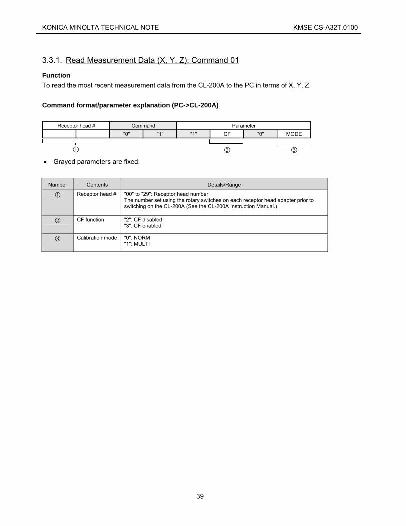
3.3.1. Read Measurement Data (X, Y, Z): Command 01
Function To read the most recent measurement data from the CL-200A to the PC in terms of X, Y, Z. Command format/parameter explanation (PC->CL-200A)
"0" "1" "1" CF "0" MODEReceptor head # Command Parameter
• Grayed parameters are fixed.
Number Contents Details/Range
Receptor head # "00" to "29": Receptor head number The number set using the rotary switches on each receptor head adapter prior to switching on the CL-200A (See the CL-200A Instruction Manual.)
CF function "2": CF disabled "3": CF enabled
Calibration mode "0": NORM "1": MULTI
39

KONICA MINOLTA TECHNICAL NOTE KMSE CS-A32T.0100
Command response format/status explanation (CL-200A->PC)
"0" "1" "1" or "5" ERR RNG BA X Y ZReceptor head # Command Status Data
• Grayed parameters are fixed.
Number Contents Details/Range
Receptor head # "00" to "29"
(Fixed value) "1" or "5"
Normal operation
Normal operation
"1" Receptor head power is switched off. Switch off the CL-200A and then switch it back on, and repeat the procedure from the beginning.
"2" EEPROM error 1 Switch off the CL-200A and then switch it back on, and repeat the procedure from the beginning.
"3" EEPROM error 2 Switch off the CL-200A and then switch it back on, and repeat the procedure from the beginning.
"4" Normal operation
"5" Measurement value over error Displayed when the measurement exceeds the CL-200A measurement range. If this error occurs, the measurement values should not be used as the values for the most recent measurement. If this error occurs repeatedly, reduce the luminance or increase the distance between the light source and measuring instrument. However, if this error occurs together with out-of-range error (RNG="6") then measures to resolve the over-range error should be given precedence.
"6" Normal operation
ERR: Error information
"7" Normal operation
"0" Range not determined Measurement could not be taken because the range could not be determined. The wait period for the prior command sent or command response received may have been incorrect. Set the correct wait time, and then perform the measurement again.
"1" to "4"
Normal
RNG: Range status
"6" Out of range The measurement could not be taken in a suitable range. Perform EXT mode (command "40") again. This will cause the range to automatically be changed (the CL-200A is equipped with 4 measuring ranges, so it may be necessary to repeat this procedure a maximum of 3 times). If this error occurs, the measurement values should not be used as the values for the most recent measurement.
"0" Normal BA: Battery level
"1" Low battery The battery should be changed immediately or the AC adapter should be used. Also, if this error occurs, the measurement values should not be used as the values for the most recent measurement.
X, Y, Z Measurement values in terms of X, Y, Z (For details of how to read the data, refer to p. 34.)
40

KONICA MINOLTA TECHNICAL NOTE KMSE CS-A32T.0100
3.3.2. Read Measurement Data (EV, x, y): Command 02
Function To read the most recent measurement data from the CL-200A to the PC in terms of EV, x, y. Command format/parameter explanation (PC->CL-200A)
"0" "2" "1" CF "0" MODEReceptor head # Command Parameter
• Grayed parameters are fixed.
Number Contents Details/Range
Receptor head # "00" to "29": Receptor head number The number set using the rotary switches on each receptor head adapter prior to switching on the CL-200A (See the CL-200A Instruction Manual.)
CF function "2": CF disabled "3": CF enabled
Calibration mode "0": NORM "1": MULTI
Command response format/status explanation (CL-200A->PC)
"0" "2" "1" or "5" ERR RNG BA EV x yReceptor head # Command Status Data
• Grayed parameters are fixed.
Number Contents Details/Range
Receptor head # "00" to "29"
(Fixed value) "1" or "5"
Normal operation
Normal operation
"1" Receptor head power is switched off. Switch off the CL-200A and then switch it back on, and repeat the procedure from the beginning.
"2" EEPROM error 1 Switch off the CL-200A and then switch it back on, and repeat the procedure from the beginning.
ERR: Error information
"3" EEPROM error 2 Switch off the CL-200A and then switch it back on, and repeat the procedure from the beginning.
41

KONICA MINOLTA TECHNICAL NOTE KMSE CS-A32T.0100
"4" Normal operation
"5" Measurement value over error Displayed when the measurement exceed the CL-200A measurement range. If this error occurs, the measurement values should not be used as the values for the most recent measurement. If this error occurs repeatedly, reduce the luminance or increase the distance between the light source and measuring instrument. However, if this error occurs together with out-of-range error (RNG="6") then measures to resolve the over-range error should be given precedence.
"6" Low luminance error Luminance is low, resulting in reduced calculation accuracy for determining chromaticity. If this error continues to occur, increase the luminance of the light source or move the receptor head closer to the light source. However, if this error occurs together with out-of-range error (RNG="6") then measures to resolve the over-range error should be given precedence.
"7" Normal operation
"0" Range not determined Measurement could not be taken because the range could not be determined. The wait period for the prior command sent or command response received may have been incorrect. Set the correct wait time, and then perform the measurement again.
"1" to "4"
Normal
RNG: Range status
"6" Out of range The measurement could not be taken in a suitable range. Perform EXT mode (command "40") again. This will cause the range to automatically be changed (the CL-200A is equipped with 4 measuring ranges, so it may be necessary to repeat this procedure a maximum of 3 times). If this error occurs, the measurement values should not be used as the values for the most recent measurement.
"0" Normal BA: Battery level
"1" Low battery The battery should be changed immediately or the AC adapter should be used. Also, if this error occurs, the measurement values should not be used as the values for the most recent measurement.
EV, x, y Measurement values in terms of EV, x, y (For details of how to read the data, refer to p. 34.)
42
KONICA MINOLTA TECHNICAL NOTE KMSE CS-A32T.0100
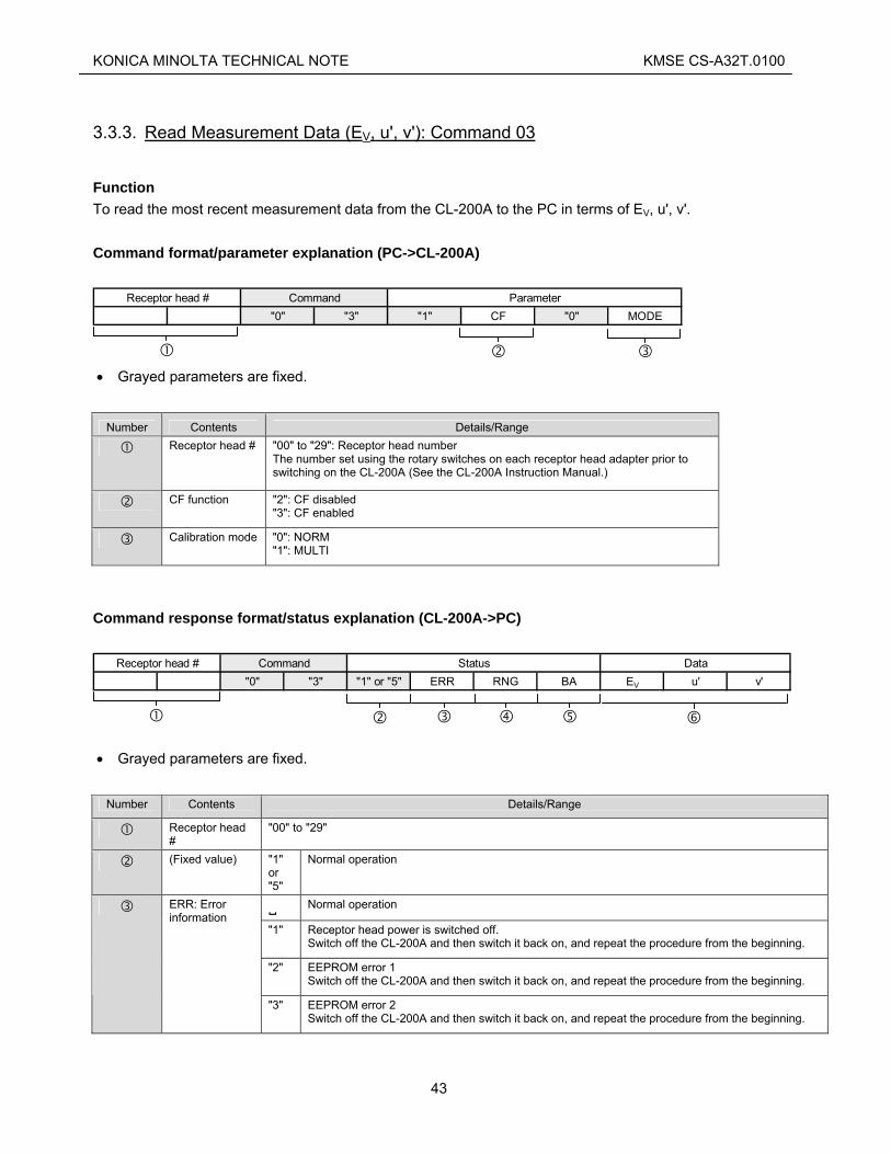
3.3.3. Read Measurement Data (EV, u', v'): Command 03
Function To read the most recent measurement data from the CL-200A to the PC in terms of EV, u', v'. Command format/parameter explanation (PC->CL-200A)
"0" "3" "1" CF "0" MODEReceptor head # Command Parameter
• Grayed parameters are fixed.
Number Contents Details/Range
Receptor head # "00" to "29": Receptor head number The number set using the rotary switches on each receptor head adapter prior to switching on the CL-200A (See the CL-200A Instruction Manual.)
CF function "2": CF disabled "3": CF enabled
Calibration mode "0": NORM "1": MULTI
Command response format/status explanation (CL-200A->PC)
"0" "3" "1" or "5" ERR RNG BA EV u' v'Receptor head # Command Status Data
• Grayed parameters are fixed.
Number Contents Details/Range
Receptor head #
"00" to "29"
(Fixed value) "1" or "5"
Normal operation
Normal operation
"1" Receptor head power is switched off. Switch off the CL-200A and then switch it back on, and repeat the procedure from the beginning.
"2" EEPROM error 1 Switch off the CL-200A and then switch it back on, and repeat the procedure from the beginning.
ERR: Error information
"3" EEPROM error 2 Switch off the CL-200A and then switch it back on, and repeat the procedure from the beginning.
43

KONICA MINOLTA TECHNICAL NOTE KMSE CS-A32T.0100
"4" Normal operation
"5" Measurement value over error Displayed when the measurement exceed the CL-200A measurement range. If this error occurs, the measurement values should not be used as the values for the most recent measurement. If this error occurs repeatedly, reduce the luminance or increase the distance between the light source and measuring instrument. However, if this error occurs together with out-of-range error (RNG="6") then measures to resolve the over-range error should be given precedence.
"6" Low luminance error Luminance is low, resulting in reduced calculation accuracy for determining chromaticity. If this error continues to occur, increase the luminance of the light source or move the receptor head closer to the light source. However, if this error occurs together with out-of-range error (RNG="6") then measures to resolve the over-range error should be given precedence.
"7" Normal operation
"0" Range not determined Measurement could not be taken because the range could not be determined. The wait period for the prior command sent or command response received may have been incorrect. Set the correct wait time, and then perform the measurement again.
"1" to "4"
Normal
RNG: Range status
"6" Out of range The measurement could not be taken in a suitable range. Perform EXT mode (command "40") again. This will cause the range to automatically be changed (the CL-200A is equipped with 4 measuring ranges, so it may be necessary to repeat this procedure a maximum of 3 times). If this error occurs, the measurement values should not be used as the values for the most recent measurement.
"0" Normal BA: Battery level
"1" Low battery The battery should be changed immediately or the AC adapter should be used. Also, if this error occurs, the measurement values should not be used as the values for the most recent measurement.
EV, u', v' Measurement values in terms of EV, u', v' (For details of how to read the data, refer to p. 34.)
44

KONICA MINOLTA TECHNICAL NOTE KMSE CS-A32T.0100
3.3.4. Read Measurement Data (EV, TCP, Δuv): Command 08
Function To read the most recent measurement data from the CL-200A to the PC in terms of EV, TCP, Δuv. Command format/parameter explanation (PC->CL-200A)
"0" "8" "1" CF "0" MODEReceptor head # Command Parameter
• Grayed parameters are fixed.
Number Contents Details/Range
Receptor head # "00" to "29": Receptor head number The number set using the rotary switches on each receptor head adapter prior to switching on the CL-200A (See the CL-200A Instruction Manual.)
CF function "2": CF disabled "3": CF enabled
Calibration mode "0": NORM "1": MULTI
Command response format/status explanation (CL-200A->PC)
"0" "8" "1" or "5" ERR RNG BA EV TCP ΔuvReceptor head # Command Status Data
• Grayed parameters are fixed.
Number Contents Details/Range
Receptor head #
"00" to "29"
(Fixed value) "1" or "5"
Normal operation
Normal operation
"1" Receptor head power is switched off. Switch off the instrument and then switch it back on, and repeat the procedure from the beginning.
ERR: Error information
"2" EEPROM error 1 Switch off the instrument and then switch it back on, and repeat the procedure from the beginning.
45

KONICA MINOLTA TECHNICAL NOTE KMSE CS-A32T.0100
"3" EEPROM error 2 Switch off the instrument and then switch it back on, and repeat the procedure from the beginning.
"4" Normal operation
"5" Measurement value over error Displayed when the measurement exceeds the instrument measurement range. If this error occurs, the measurement values should not be used as the values for the most recent measurement. If this error occurs repeatedly, reduce the luminance or increase the distance between the light source and measuring instrument. However, if this error occurs together with out-of-range error (RNG="6") then measures to resolve the over-range error should be given precedence.
"6" Low luminance error Luminance is low, resulting in reduced calculation accuracy for determining chromaticity. If this error continues to occur, increase the luminance of the light source or move the receptor head closer to the light source. However, if this error occurs together with out-of-range error (RNG="6") then measures to resolve the over-range error should be given precedence.
"7" Value out of range The TCP, Δuv measurement is out of range. If this error occurs together with out-of-range error (RNG="6") then measures to resolve the over-range error should be given precedence.
"0" Range not determined Measurement could not be taken because the range could not be determined. The wait period for the prior command sent or command response received may have been incorrect. Set the correct wait time, and then perform the measurement again.
"1" to "4"
Normal
RNG: Range status
"6" Out of range The measurement could not be taken in a suitable range. Perform EXT mode (command "40") again. This will cause the range to automatically be changed (the CL-200A is equipped with 4 measuring ranges, so it may be necessary to repeat this procedure a maximum of 3 times). If this error occurs, the measurement values should not be used as the values for the most recent measurement.
"0" Normal BA: Battery level
"1" Low battery The battery should be changed immediately or the AC adapter should be used. Also, if this error occurs, the measurement values should not be used as the values for the most recent measurement.
EV, TCP, Δuv Measurement values in terms of EV, TCP, Δuv (For details of how to read the data, refer to p. 34.)
46

KONICA MINOLTA TECHNICAL NOTE KMSE CS-A32T.0100
3.3.5. Read Measurement Data (EV, DW, P): Command 15
• This function is available only on the CL-200A.
Function To read the most recent measurement data from the CL-200A to the PC in terms of Ev, DW (Dominant wavelength), P (Excitation purity). Command format/parameter explanation (PC->CL-200A)
"1" "5" "1" CF "0" MODReceptor head # Command Parameter
E
• Grayed parameters are fixed.
Number Contents Details/Range
Receptor head # "00" to "29": Receptor head number The number set using the rotary switches on each receptor head adapter prior to switching on the CL-200A (See the CL-200A Instruction Manual.)
CF function "2": CF disabled "3": CF enabled
Calibration mode "0": NORM "1": MULTI
Command response format/status explanation (CL-200A->PC)
"1" "5" "1" or "5" ERR RNG BA EV DW PReceptor head # Command Status Data
• Grayed parameters are fixed.
Number Contents Details/Range
Receptor head # "00" to "29"
(Fixed value) "1" or "5"
Normal operation
Normal operation
"1" Receptor head power is switched off. Switch off the CL-200A and then switch it back on, and repeat the procedure from the beginning.
ERR: Error information
"2" EEPROM error 1 Switch off the CL-200A and then switch it back on, and repeat the procedure from the beginning.
47

KONICA MINOLTA TECHNICAL NOTE KMSE CS-A32T.0100
"3" EEPROM error 2 Switch off the CL-200A and then switch it back on, and repeat the procedure from the beginning.
"4" Normal operation
"5" Measurement value over error Displayed when the measurement exceed the CL-200A measurement range. If this error occurs, the measurement values should not be used as the values for the most recent measurement. If this error occurs repeatedly, reduce the luminance or increase the distance between the light source and measuring instrument. However, if this error occurs together with out-of-range error (RNG="6") then measures to resolve the over-range error should be given precedence.
"6" Normal operation
"7" Normal operation
"0" Range not determined Measurement could not be taken because the range could not be determined. The wait period for the prior command sent or command response received may have been incorrect. Set the correct wait time, and then perform the measurement again.
"1" to "4"
Normal
RNG: Range status
"6" Out of range The measurement could not be taken in a suitable range. Perform EXT mode (command "40") again. This will cause the range to automatically be changed (the CL-200A is equipped with 4 measuring ranges, so it may be necessary to repeat this procedure a maximum of 3 times). If this error occurs, the measurement values should not be used as the values for the most recent measurement.
"0" Normal BA: Battery level
"1" Low battery The battery should be changed immediately or the AC adapter should be used. Also, if this error occurs, the measurement values should not be used as the values for the most recent measurement.
EV, DW, P Measurement values in terms of EV, DW, P (For details of how to read the data, refer to p. 34.)
48

KONICA MINOLTA TECHNICAL NOTE KMSE CS-A32T.0100
3.3.6. Set EXT mode: Command 40
Function Sets the CL-200A to the mode for controlling measurements from the PC, and takes measurements. • Before sending this command, the CL-200A must be set to Hold status using command 55).
1 Set CL-200A to EXT mode • Wait at least 500ms after receiving the command response before sending further commands.
Command format/parameter explanation (PC->CL-200A)
"4" "0" "1" "0"
Receptor head # Command Parameter
• Grayed parameters are fixed.
Number Contents Details/Range Receptor head # "00" to "29": Receptor head number
The number set using the rotary switches on each receptor head adapter prior to switching on the CL-200A (See the CL-200A Instruction Manual.)
Command response format/status explanation (CL-200A->PC)
"4" "0" ERR
Receptor head # Command Status
• Grayed parameters are fixed.
Number Contents Details/Range
Receptor head # "00" to "29"
Normal operation
"1" Receptor head power is switched off. Switch off the CL-200A and then switch it back on, and repeat the procedure from the beginning.
"2" EEPROM error 1 Switch off the CL-200A and then switch it back on, and repeat the procedure from the beginning.
ERR: Error information
"3" EEPROM error 2 Switch off the CL-200A and then switch it back on, and repeat the procedure from the beginning.
49
KONICA MINOLTA TECHNICAL NOTE KMSE CS-A32T.0100
"4" EXT error Occurs when this command is sent to the CL-200A without first setting the CL-200A to Hold status. Send the command "55" to the CL-200A to set it to Hold status, and then send this command again.
"5" Normal operation (Indicates that the measurement immediately preceding the sending of this command returned a "Measurement value over" error. Does not affect subsequent measurements.)
"6" Normal operation (Indicates that the measurement immediately preceding the sending of this command returned a "Low luminance" error. Does not affect subsequent measurements.)
"7" Normal operation (Indicates that the measurement immediately preceding the sending of this command returned a "Value out of range" error. Does not affect subsequent measurements.)
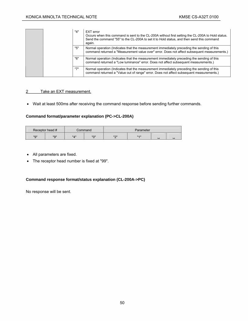
2 Take an EXT measurement. • Wait at least 500ms after receiving the command response before sending further commands.
Command format/parameter explanation (PC->CL-200A)
Receptor head # Command Parameter
"9" "9" "4" "0" "2" "1" • All parameters are fixed. • The receptor head number is fixed at "99".
Command response format/status explanation (CL-200A->PC) No response will be sent.
50

KONICA MINOLTA TECHNICAL NOTE KMSE CS-A32T.0100
3.3.7. Read Measurement Data (X2, Y, Z): Command 45
Function To read the most recent measurement data from the CL-200A to the PC in terms of X2, Y, Z. Command format/parameter explanation (PC->CL-200A)
"4" "5" "1" "0" "0" "0"Receptor head # Command Parameter
• Grayed parameters are fixed.
Number Contents Details/Range Receptor head # "00" to "29": Receptor head number
The number set using the rotary switches on each receptor head adapter prior to switching on the CL-200A (See the CL-200A Instruction Manual.)
Command response format/status explanation (CL-200A->PC)
"4" "5" "1" or "5" ERR RNG BA EV DW PReceptor head # Command Status Data
• Grayed parameters are fixed.
Number Contents Details/Range
Receptor head #
"00" to "29"
(Fixed value) "1" or "5"
Normal operation
Normal operation
"1" Receptor head power is switched off. Switch off the CL-200A and then switch it back on, and repeat the procedure from the beginning.
"2" EEPROM error 1 Switch off the CL-200A and then switch it back on, and repeat the procedure from the beginning.
"3" EEPROM error 2 Switch off the CL-200A and then switch it back on, and repeat the procedure from the beginning.
ERR: Error information
"4" Normal operation
51

KONICA MINOLTA TECHNICAL NOTE KMSE CS-A32T.0100
"5" Measurement value over error Displayed when the measurement exceeds the CL-200A measurement range. If this error occurs, the measurement values should not be used as the values for the most recent measurement. If this error occurs repeatedly, reduce the luminance or increase the distance between the light source and measuring instrument. However, if this error occurs together with out-of-range error (RNG="6") then measures to resolve the over-range error should be given precedence.
"6" Normal operation
"7" Normal operation
"0" Range not determined Measurement could not be taken because the range could not be determined. The wait period for the prior command sent or command response received may have been incorrect. Set the correct wait time, and then perform the measurement again.
"1" to "4"
Normal
RNG: Range status
"6" Out of range The measurement could not be taken in a suitable range. Perform EXT mode (command "40") again. This will cause the range to automatically be changed (the CL-200A is equipped with 4 measuring ranges, so it may be necessary to repeat this procedure a maximum of 3 times). If this error occurs, the measurement values should not be used as the values for the most recent measurement.
"0" Normal BA: Battery level
"1" Low battery The battery should be changed immediately or the AC adapter should be used. Also, if this error occurs, the measurement values should not be used as the values for the most recent measurement.
X2, Y, Z Measurement values in terms of X2, Y, Z (For details of how to read the data, refer to Special format on p. 35.)
52

KONICA MINOLTA TECHNICAL NOTE KMSE CS-A32T.0100
3.3.8. Read User Calibration Coefficients: Command 47
Function To read the user calibration coefficients currently set on the CL-200A. These coefficients are used when the CL-200A is set to CF Mode: On and Calibration Mode: Multi. Command format/parameter explanation (PC->CL-200A)
"4" "7" MCF "1"
Receptor head # Command Parameter
• Grayed parameters are fixed.
Number Contents Details/Range Receptor head # "00" to "29": Receptor head number
The number set using the rotary switches on each receptor head adapter prior to switching on the CL-200A (See the CL-200A Instruction Manual.)
User calibration coefficient matrix row number
"1" to "3" The number of the user calibration coefficient matrix row to be read. A11 A12 A13 Row 1 A21 A22 A23 Row 2 A31 A32 A33 Row 3
Command response format/status explanation (CL-200A->PC)
"4" "7" "0" or "1" ERR Ax1 Ax2 Ax3
Receptor head # Command Status Data
• Grayed parameters are fixed.
Number Contents Details/Range
Receptor head #
"00" to "29"
(Fixed value) "0" or "1"
Normal operation
Normal operation
"1" Receptor head power is switched off. Switch off the CL-200A and then switch it back on, and repeat the procedure from the beginning.
"2" EEPROM error 1 Switch off the CL-200A and then switch it back on, and repeat the procedure from the beginning.
ERR: Error information
"3" EEPROM error 2 Switch off the CL-200A and then switch it back on, and repeat the procedure from the beginning.
53

KONICA MINOLTA TECHNICAL NOTE KMSE CS-A32T.0100
"4" Normal operation
"5" Normal operation
"6" Normal operation
"7" Normal operation
Ax1, Ax2, Ax3, User calibration coefficients Ax1, Ax2, Ax3, for the specified user calibration matrix row stored in the instrument (For details of how to read the data, refer to Special format on p. 35.)
54

KONICA MINOLTA TECHNICAL NOTE KMSE CS-A32T.0100
3.3.9. Write User Calibration Coefficients: Command 48
Function To write the user calibration coefficients currently set on the CL-200A. These coefficients are used when the CL-200A is set to CF Mode: On and Calibration Mode: Multi. Command format/parameter explanation (PC->CL-200A)
Receptor head # Command Status Data
"4" "8" MCF "1" Ax1 Ax2 Ax3
• Grayed parameters are fixed.
Number Contents Details/Range Receptor head # "00" to "29": Receptor head number
The number set using the rotary switches on each receptor head adapter prior to switching on the CL-200A (See the CL-200A Instruction Manual.)
User calibration coefficient matrix row number
"1" to "3" The number of the user calibration coefficient matrix row to be read. A11 A12 A13 Row 1 A21 A22 A23 Row 2 A31 A32 A33 Row 3
Ax1, Ax2, Ax3, User calibration coefficients Ax1, Ax2, Ax3, for the specified user calibration matrix row stored in the instrument (For details of how to read the data, refer to Special format on p. xx.)
Command response format/status explanation (CL-200A->PC)
Receptor head # Command Status
"4" "8" ERR
• Grayed parameters are fixed.
Number Contents Details/Range
Receptor head #
"00" to "29"
Normal operation
"1" Receptor head power is switched off. Switch off the CL-200A and then switch it back on, and repeat the procedure from the beginning.
ERR: Error information
"2" EEPROM error 1 Switch off the CL-200A and then switch it back on, and repeat the procedure from the beginning.
55

KONICA MINOLTA TECHNICAL NOTE KMSE CS-A32T.0100
"3" EEPROM error 2 Switch off the CL-200A and then switch it back on, and repeat the procedure from the beginning.
"4" Outside setting range. The input coefficient values are outside the valid setting range
"5" Normal operation
"6" Normal operation
"7" Normal operation
56
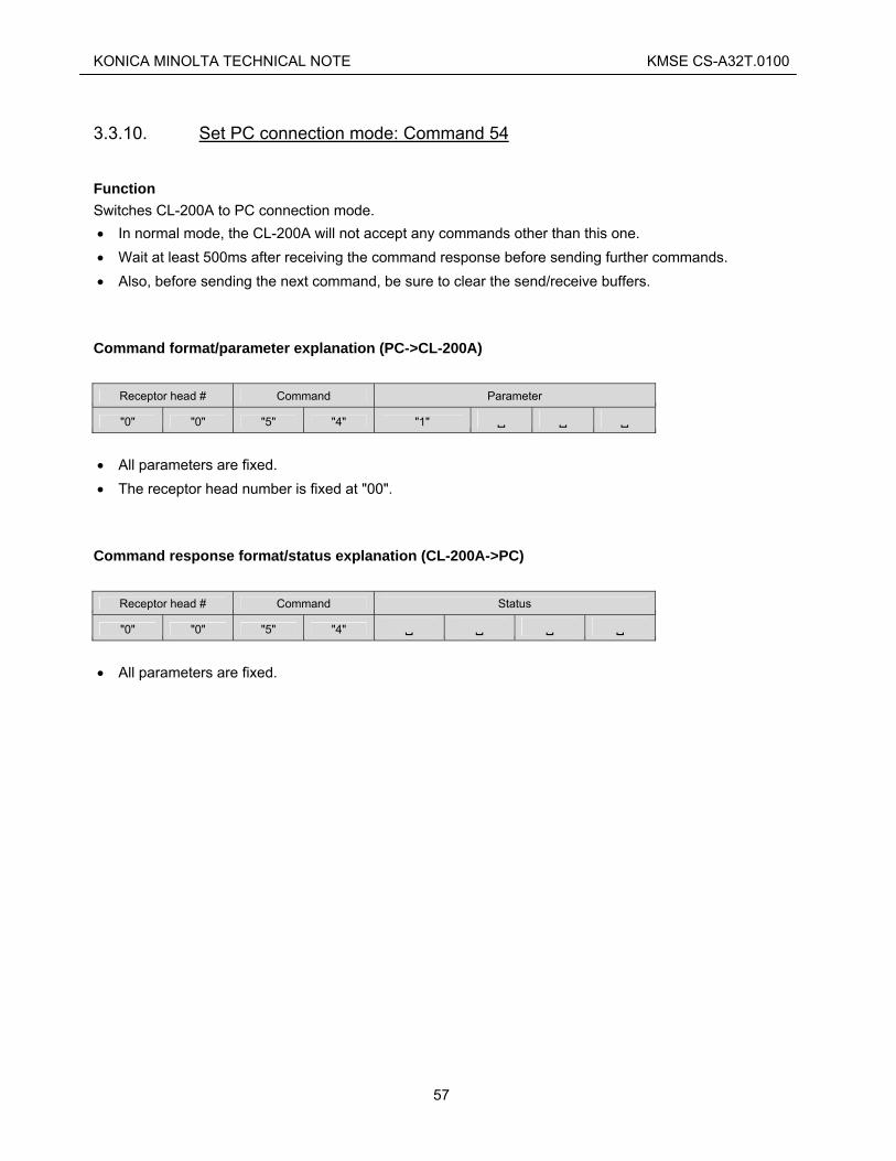
KONICA MINOLTA TECHNICAL NOTE KMSE CS-A32T.0100
3.3.10. Set PC connection mode: Command 54
Function Switches CL-200A to PC connection mode. • In normal mode, the CL-200A will not accept any commands other than this one. • Wait at least 500ms after receiving the command response before sending further commands. • Also, before sending the next command, be sure to clear the send/receive buffers.
Command format/parameter explanation (PC->CL-200A)
Receptor head # Command Parameter
"0" "0" "5" "4" "1" • All parameters are fixed. • The receptor head number is fixed at "00".
Command response format/status explanation (CL-200A->PC)
Receptor head # Command Status
"0" "0" "5" "4" • All parameters are fixed.
57

KONICA MINOLTA TECHNICAL NOTE KMSE CS-A32T.0100
3.3.11. Set Hold status: Command 55
Function Sets the CL-200A to Hold status. • Wait at least 500ms after receiving the command response before sending further commands.
Command format/parameter explanation (PC->CL-200A)
Receptor head # Command Parameter
"9" "9" "5" "5" "1" "0"
• All parameters are fixed. • The receptor head number is fixed at "99".
Command response format/status explanation (CL-200A->PC) No response will be sent.
58

KONICA MINOLTA TECHNICAL NOTE KMSE CS-A32T.0100
59
3.4. Error Codes
Code Meaning Details
(space)
Normal No error (normal)
"1" POW-ON Indicates that power to the head has been cut off. Turn the CL-200A off and then back on.
"2" EEPROM error 1
"3" EEPROM error 2
An improper value has been written to the receptor head's EEPROM. Turn the CL-200A power off and then back on. If the problem recurs, the unit requires service.
"4" EXT error Occurs when command 40 (set EXT mode) was sent to the CL-200A without first setting the CL-200A to Hold status. Send the command "55" to the CL-200A to set it to Hold status, and then send command 40 again.
Displayed when the measurement exceeds the CL-200A measurement range. "5" Measurement value over error
If this error occurs, the measurement values should not be used as the values for the most recent measurement. If this error occurs repeatedly, reduce the luminance or increase the distance between the light source and measuring instrument.
Luminance is low, resulting in reduced calculation accuracy for determining chromaticity and correlated color temperature.
"6" Low luminance error
Measurement was taken correctly, so there is no serious problem. However, if this error continues to occur, increase the luminance of the light source or move the receptor head closer to the light source.
"7" Value out of range The TCP, Δuv measured values are out of range.