christopher nantista slac tilc09 tsukuba, japan april 20, 2009
TRANSCRIPT
Christopher NantistaSLAC
TILC09Tsukuba, JapanApril 20, 2009
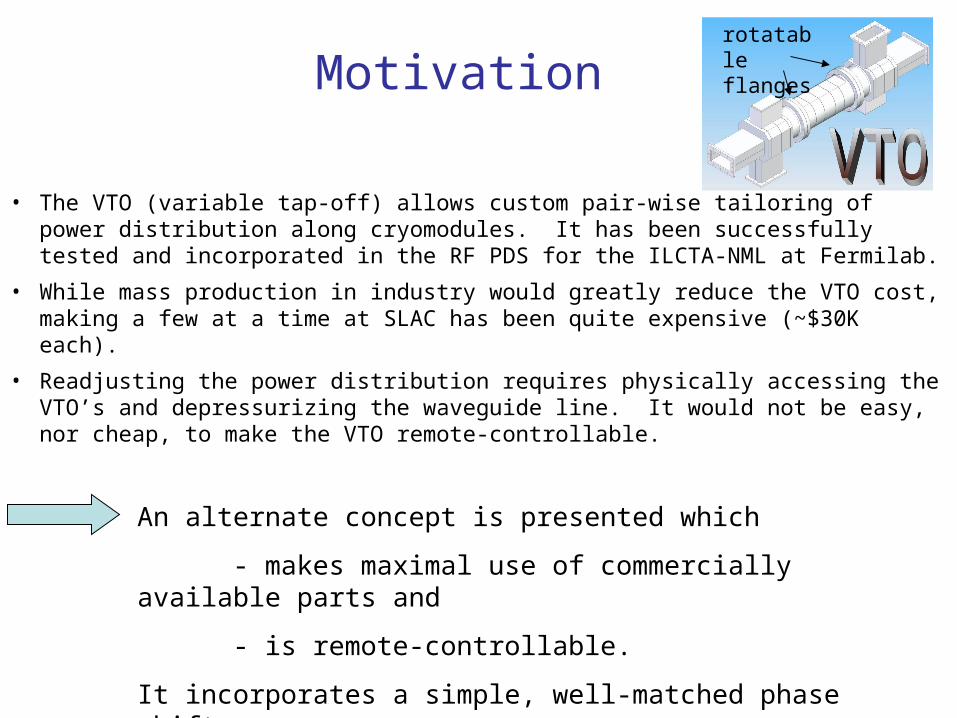
• The VTO (variable tap-off) allows custom pair-wise tailoring of power distribution along cryomodules. It has been successfully tested and incorporated in the RF PDS for the ILCTA-NML at Fermilab.
• While mass production in industry would greatly reduce the VTO cost, making a few at a time at SLAC has been quite expensive (~$30K each).
• Readjusting the power distribution requires physically accessing the VTO’s and depressurizing the waveguide line. It would not be easy, nor cheap, to make the VTO remote-controllable.
Motivationrotatable flanges
An alternate concept is presented which
- makes maximal use of commercially available parts and
- is remote-controllable.
It incorporates a simple, well-matched phase shifter.

Ee (extracted)
Et
(transmitted)
⎟⎟⎟⎟⎟
⎠
⎞
⎜⎜⎜⎜⎜
⎝
⎛
−
−=
0011
0011
1100
1100
2
1S1
2
3
1
2
11
φieE =
2
2
12
φieE =
Tailoring Power Distribution with Pase Shifters and Magic-Tees
( )( )
( ) ( )( )
( ) ⎟⎠
⎞⎜⎝
⎛ −=+=⎟
⎠
⎞⎜⎝
⎛ +=
⎟⎠
⎞⎜⎝
⎛ −−=
−=−=⎟⎠
⎞⎜⎝
⎛ −=
⎟⎠
⎞⎜⎝
⎛ +
⎟⎠
⎞⎜⎝
⎛ +
−−−+
2cos
2
1
22
2sin
22
1
22
12221
122
2/2/2/
21
21
21
21
1212
12
21
φφ
φφ
φφφφ
φφ
φφφφφφ
φφ
iii
t
i
iii
iie
eeeEE
E
ie
eee
eeEE
E
If 1 and 2 are changed in opposite senses by half the desired , the coupled and through phases are unaffected as the amplitudes are adjusted.
4
Magic-T w/ equal-amplitude in-line port inputs
⎟⎠
⎞⎜⎝
⎛=
⎟⎠
⎞⎜⎝
⎛−=
⎟⎠
⎞⎜⎝
⎛ +
⎟⎠
⎞⎜⎝
⎛ +
2cos
2sin
2
2
21
21
φ
φ
φφ
φφ
i
t
i
e
eE
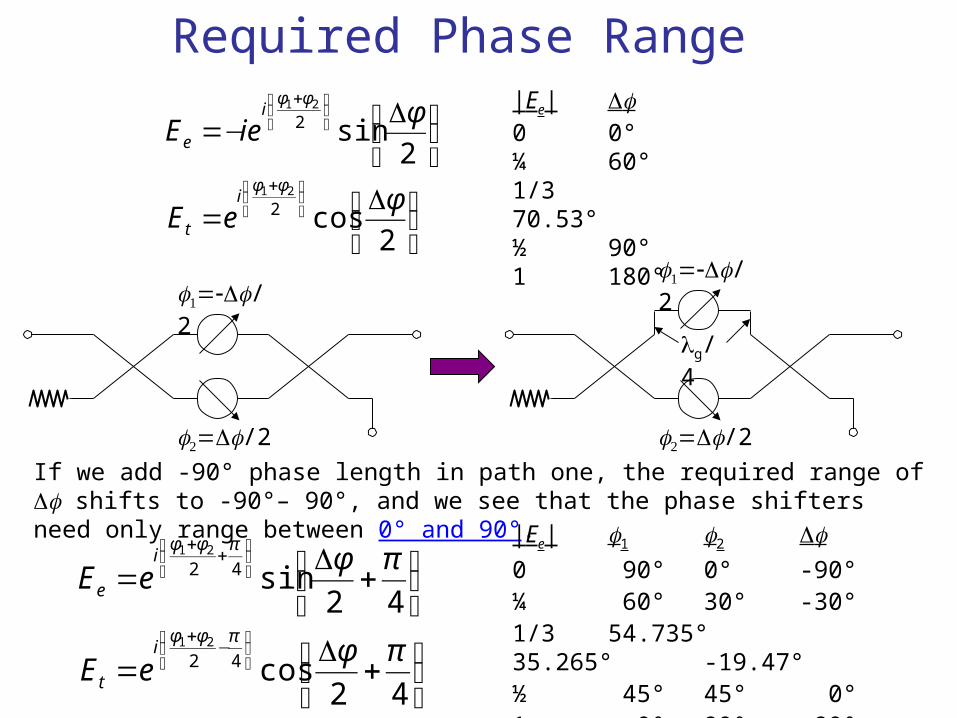
ieE|Ee| 0 0°¼ 60°1/3 70.53°½ 90°1 180°
/2
/2
⎟⎠
⎞⎜⎝
⎛ +
=
⎟⎠
⎞⎜⎝
⎛ +
=
⎟⎠
⎞⎜⎝
⎛ −+
⎟⎠
⎞⎜⎝
⎛ ++
42cos
42sin
42
42
21
21
πφ
πφ
πφφ
πφφ
i
t
i
e
eE
eE
If we add -90° phase length in path one, the required range of shifts to -90°– 90°, and we see that the phase shifters need only range between 0° and 90°.
|Ee| 1 2 0 90° 0° -90°¼ 60° 30° -30°1/3 54.735° 35.265° -19.47°½ 45° 45° 0°1 0° 90° 90°
/2
/2
g/4
Required Phase Range

in-line phase shiftershybrids & plungers
reflections too large for main line (up to -23 dB for DESY/SPA Ferrite design, fine in feeds buffered by circulators)
bulky & complicated; possible large reflections if shorts don’t track
Possible Configurations
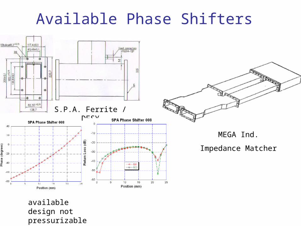
Available Phase Shifters
MEGA Ind.
Impedance Matcher
S.P.A. Ferrite / DESY
available design not pressurizable

Trombone Phase Shifter
• takes advantage of required U-bends;
• match ideally unaffected by position;
• no bellows
pressurized outer box
moving inner waveguide

3.925”3.000”
3.010”
2.750”
6.250”
r=0.125”
RF Design
S =
|E| |H|needed motion range:
g/8 = 1.586”
(path change = g/4)

~1.91% is coupled into the 0.083” gap, with very little reflection.
The Gap Problem
Non-negligible power couples into gap between moving waveguide and outer walls.
The excited gap mode has different wavelength than the interior waveguide mode.
Gap is connected to open volumes that change as phase shifter is moved.
Potential gap resonances can ruin match, absorb power, and cause breakdown.
reflection
transmission
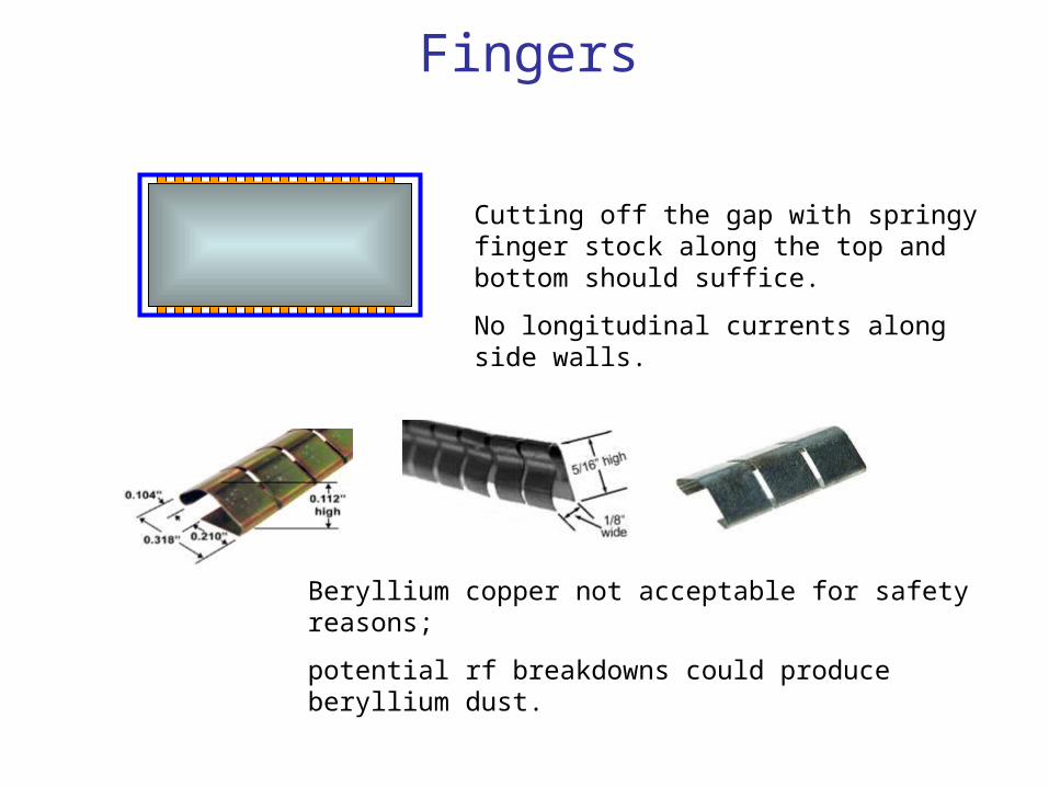
Fingers
Cutting off the gap with springy finger stock along the top and bottom should suffice.
No longitudinal currents along side walls.
Beryllium copper not acceptable for safety reasons;
potential rf breakdowns could produce beryllium dust.

-48.7 dB → -89.8 dB -8.21 dB (15%) → -69.0 dB
1 2 1 2
Test of Effect of Fingers Along Top and Bottom of Waveguide Insert
3.25” 4.63”~2 mm gap
WR650
fingers
transmission around closed box inserts measured
w/ & w/out fingers
0 0.5 1 1.5 2 2.5 3 3.50
0.5
1
1.5
2
2.5
3
3.5
Time: Hrs
Power to DUT: MW
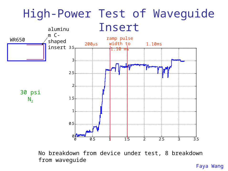
30 psi N2
200sramp pulse
width to 1.10 ms 1.10ms
No breakdown from device under test, 8 breakdown from waveguide
Faya Wang
High-Power Test of Waveguide Insert
WR650
aluminum C-shaped insert

pressurizable WR650 spools
4 threaded blind holes
weld
2” travel
Conceptual Mechanical Design
teflon spacers
finger stock
engineer’spreliminary drawing
-1 -0.8 -0.6 -0.4 -0.2 0 0.2 0.4 0.6 0.8 1
-80
-60
-40
-20
0
20
40
60
80
100
120
Inward Displacement (inches)
Phase (blue, degrees) & S
11
(red, dB)
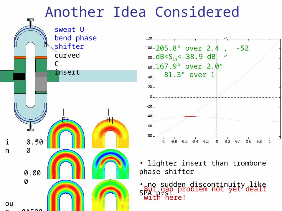
Another Idea Consideredswept U-bend phase shifter
205.8° over 2.4”, -52 dB<S11<-38.9 dB167.9° over 2.0” 81.3° over 1”
0.500”
-0.500”
0.000”
out
in
|E| |H|
• lighter insert than trombone phase shifter
• no sudden discontinuity like SPA p.s.
curved C insert
But gap problem not yet dealt with here!