choppers
DESCRIPTION
DC choppersTRANSCRIPT

Power Electronics
1
DC CHOPPERS
1
Introduction• Chopper is a static device.• A variable dc voltage is obtained from a constant dc voltage
source.• Also known as dc-to-dc converter.• Widely used for motor control.• Also used in regenerative braking.• Thyristor converter offers greater efficiency, faster response,
lower maintenance, smaller size and smooth control.
•22Prof. T.K. Anantha Kumar, E&E Dept., MSRIT

Power Electronics
2
Choppers are of Two Types
Step-down choppers. In step down chopper output voltage is less than input
voltage.
Step-up choppers. In step up chopper output voltage is more than input
voltage.
3Prof. T.K. Anantha Kumar, E&E Dept., MSRIT
Principle Of Step-down Chopper
V
i0
V0
Chopper
R
+
•44Prof. T.K. Anantha Kumar, E&E Dept., MSRIT

Power Electronics
3
• A step-down chopper with resistive load.
• The thyristor in the circuit acts as a switch.
• When thyristor is ON, supply voltage appears acrossthe load
• When thyristor is OFF, the voltage across the load willbe zero. 5
Prof. T.K. Anantha Kumar, E&E Dept., MSRIT
V d c
v 0
V
V /R
i0
I d c
t
t
t O N
T
t O F F
6Prof. T.K. Anantha Kumar, E&E Dept., MSRIT

Power Electronics
4
7Prof. T.K. Anantha Kumar, E&E Dept., MSRIT
v e r a g e v a l u e o f o u t p u t o r l o a d v o l t a g e .
v e r a g e v a l u e o f o u t p u t o r l o a d c u r r e n t .
T i m e i n t e r v a l f o r w h i c h S C R c o n d u c t s .
T i m e i n t e r v a l f o r w h i c h S C R i s O F F .
P e r i o d o f s w i t c h i n g
d c
d c
O N
O F F
O N O F F
V A
I A
t
t
T t t
o r c h o p p i n g p e r i o d .
1 F r e q . o f c h o p p e r s w i t c h i n g o r c h o p p i n g f r e q .f
T
8Prof. T.K. Anantha Kumar, E&E Dept., MSRIT
A v e r a g e O u t p u t V o l t a g e
.
d u t y c y c l e
O Nd c
O N O F F
O Nd c
O N
tV V
t t
tV V V d
T
tb u t d
t
Power Electronics
5
9Prof. T.K. Anantha Kumar, E&E Dept., MSRIT
2
0
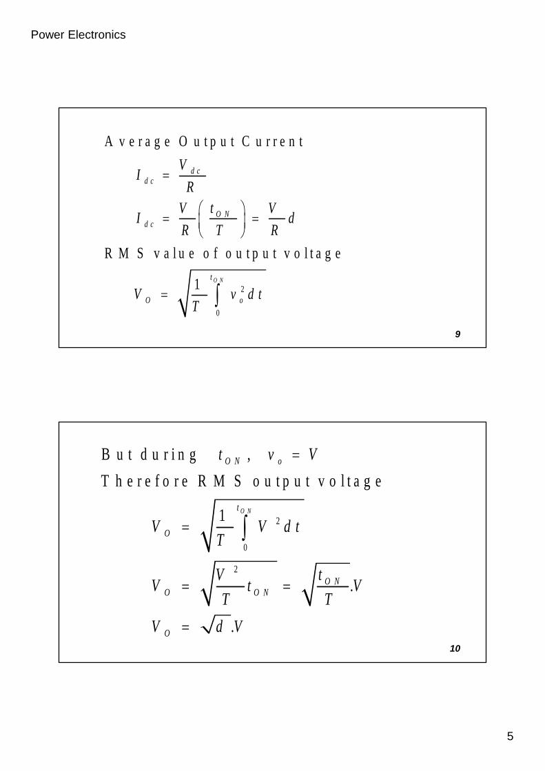
A v e r a g e O u t p u t C u r r e n t
R M S v a l u e o f o u t p u t v o l t a g e
1 O N
d cd c
O Nd c
t
O o
VI
RtV V
I dR T R
V v d tT
10Prof. T.K. Anantha Kumar, E&E Dept., MSRIT
2
0
2
B u t d u r i n g ,
T h e r e f o r e R M S o u t p u t v o l t a g e
1
.
.
O N
O N o
t
O
O NO O N
O
t v V
V V d tT
tVV t V
T T
V d V

Power Electronics
6
11Prof. T.K. Anantha Kumar, E&E Dept., MSRIT
2
2
O u t p u t p o w e r
B u t
O u t p u t p o w e r
O O O
OO
OO
O
P V I
VI
R
VP
R
d VP
R
12Prof. T.K. Anantha Kumar, E&E Dept., MSRIT
E f f e c t i v e i n p u t r e s i s t a n c e o f c h o p p e r
T h e o u t p u t v o l t a g e c a n b e v a r i e d b y
v a r y i n g t h e d u t y c y c l e .
id c
i
VR
I
RR
d

Power Electronics
7
Methods Of Control• The output dc voltage can be varied by the following
methods.– Pulse width modulation control or constant
frequency operation.– Variable frequency control.
13
Prof. T.K. Anantha Kumar, E&E Dept., MSRIT
Pulse Width Modulation• tON is varied keeping chopping frequency ‘f’ & chopping
period ‘T’ constant.• Output voltage is varied by varying the ON time tON
14Prof. T.K. Anantha Kumar, E&E Dept., MSRIT

Power Electronics
8
V 0
V
V
V 0
t
tt O N
t O N t O F F
t O F F
T
15Prof. T.K. Anantha Kumar, E&E Dept., MSRIT
Variable Frequency Control• Chopping frequency ‘f’ is varied keeping either tON or tOFF
constant.
• To obtain full output voltage range, frequency has to be variedover a wide range.
• This method produces harmonics in the output and for largetOFF load current may become discontinuous
16

Power Electronics
9
v 0
V
V
v 0
t
t
t O N
tO N
T
T
t O F F
tO F F
17Prof. T.K. Anantha Kumar, E&E Dept., MSRIT
Step-down ChopperWith R-L Load
V
i 0
V 0
C h o p p e r
R
LF W D
E
+
18Prof. T.K. Anantha Kumar, E&E Dept., MSRIT

Power Electronics
10
• When chopper is ON, supply is connected across load.• Current flows from supply to load.• When chopper is OFF, load current continues to flow in the
same direction through FWD due to energy stored in inductor‘L’.
• Load current can be continuous or discontinuous dependingon the values of ‘L’ and duty cycle ‘d’
• For a continuous current operation, load current variesbetween two limits Imax and Imin
• When current becomes equal to Imax the chopper is turned-offand it is turned-on when current reduces to Imin. 19
O u t p u tv o l t a g e
O u t p u tc u r r e n t
v 0
V
i 0
I m a x
I m i n
t
t
t O N
T
t O F F
C o n t i n u o u sc u r r e n t
O u t p u tc u r r e n t
t
D i s c o n t i n u o u sc u r r e n t
i 0
20Pro. T.K. Anantha Kumar, E&E Dept., MSRIT

Power Electronics
11
Principle Of Step-up Chopper
+
VOV
Chopper
CLOAD
DLI
+
21Prof. T.K. Anantha Kumar, E&E Dept., MSRIT
• Step-up chopper is used to obtain a load voltage higher thanthe input voltage V.
• The values of L and C are chosen depending upon therequirement of output voltage and current.
• When the chopper is ON, the inductor L is connected acrossthe supply.
• The inductor current ‘I’ rises and the inductor stores energyduring the ON time of the chopper, tON.
22Prof. T.K. Anantha Kumar, E&E Dept., MSRIT

Power Electronics
12
• When the chopper is off, the inductor current I is forced to flowthrough the diode D and load for a period, tOFF.
• The current tends to decrease resulting in reversing the polarityof induced EMF in L.
• Therefore voltage across load is given by
. . ,O O
d IV V L i e V V
d t
23Prof. T.K. Anantha Kumar, E&E Dept., MSRIT
• A large capacitor ‘C’ connected across the load, will provide acontinuous output voltage
• Diode D prevents any current flow from capacitor to thesource.
• Step up choppers are used for regenerative braking of dcmotors.
24Prof. T.K. Anantha Kumar, E&E Dept., MSRIT

Power Electronics
13
Expression For Output Voltage
25Prof. T.K. Anantha Kumar, E&E Dept., MSRIT
A s s u m e t h e a v e r a g e i n d u c t o r c u r r e n t t o b e
d u r i n g O N a n d O F F t i m e o f C h o p p e r .
V o l t a g e a c r o s s i n d u c t o r
T h e r e f o r e e n e r g y s t o r e d i n i n d u c t o r
= . .
W h e r e
W h e n C h o p p e r
p e r i o d o f c h o p p e r .
i s O N
O N
O N
I
L V
V I t
t O N
26Prof. T.K. Anantha Kumar, E&E Dept., MSRIT
( e n e r g y i s s u p p l i e d b y i n d u c t o r t o l o a d )
V o l t a g e a c r o s s
E n e r g y s u p p l i e d b y i n d u c t o r
w h e r e p e r i o d o f C h o p p e r .
N e g
W h e n C h o p p e r
l e c t i n g l o s s e s , e n e r g y s t o r e d i n i n d u c t o r
i s O F F
O
O O F F
O F F
L V V
L V V I t
t O F F
L
= e n e r g y s u p p l i e d b y i n d u c t o r L

Power Electronics
14
27Prof. T.K. Anantha Kumar, E&E Dept., MSRIT
W h e r e
T = C h o p p i n g p e r i o d o r p e r i o d
o f s w i t c h i n g .
O N O O F F
O N O F FO
O F F
OO N
V I t V V I t
V t tV
t
TV V
T t
28Prof. T.K. Anantha Kumar, E&E Dept., MSRIT
1
1
1
1
W h e r e d u t y c y l e
O N O F F
OO N
O
O N
T t t
V Vt
T
V Vd
td
T

Power Electronics
15
Classification Of Choppers
Choppers are classified as Class A Chopper Class B Chopper Class C Chopper Class D Chopper Class E Chopper
29Prof. T.K. Anantha Kumar, E&E Dept., MSRIT
Class A Chopper
V
Chopper
FWD
+
v0
v0
i0
i0
LOAD
V
30Prof. T.K. Anantha Kumar, E&E Dept., MSRIT
Class A Chopper is a first quadrant chopper .

Power Electronics
16
• When chopper is ON, supply voltage V is connected across theload.
• When chopper is OFF, vO = 0 and the load current continues toflow in the same direction through the FWD.
• The average values of output voltage and current are alwayspositive.
• Class A Chopper is a step-down chopper in which poweralways flows form source to load.
• It is used to control the speed of dc motor.• The output current equations obtained in step down chopper
with R-L load can be used to study the performance of Class AChopper. 31Prof. T.K. Anantha Kumar, E&E Dept., MSRIT
O u tp u t c u rre n t
T h y r is to rg a te p u lse
O u tp u t v o l ta g e
i g
i 0
v 0
t
t
tt O N
T
C H O N
F W D C o n d u c ts
32Prof. T.K. Anantha Kumar, E&E Dept., MSRIT

Power Electronics
17
Class B Chopper
V
Chopper
+
v0
v0
i0
i0
L
E
R
D
33Prof. T.K. Anantha Kumar, E&E Dept., MSRIT
Class B Chopper operates in second quadrant
• When chopper is ON, E drives a current through L and R in adirection opposite to that shown in figure.
• During the ON period of the chopper, the inductance L storesenergy.
• When Chopper is OFF, diode D conducts, and part of theenergy stored in inductor L is returned to the supply.
• Average output voltage is positive and average output currentis negative.
• In this chopper, power flows from load to source.• Class B Chopper is used for regenerative braking of dc motor.• Class B Chopper is a step-up chopper.
34Prof. T.K. Anantha Kumar, E&E Dept., MSRIT

Power Electronics
18
O u tp u t c u rre n t
Dc o n d u c ts C h o p p e r
c o n d u c ts
T h y r is to rg a te p u lse
O u tp u t v o lta g e
i g
i 0
v 0
t
t
t
I m in
Im a x
T
tO NtO F F
35Prof. T.K. Anantha Kumar, E&E Dept., MSRIT
Class C Chopper
V
Chopper
+
v0
D 1
D 2CH 2
CH 1
v0i0
i0
L
E
R
36Prof. T.K. Anantha Kumar, E&E Dept., MSRIT
Power Electronics
19
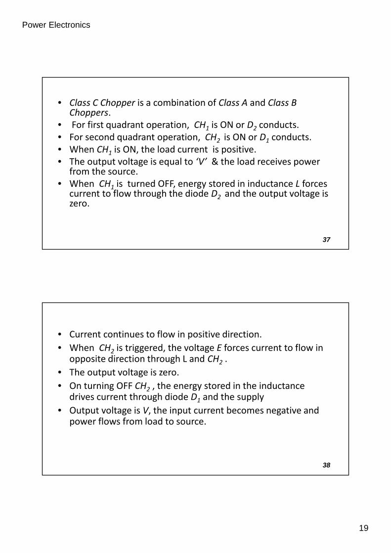
• Class C Chopper is a combination of Class A and Class BChoppers.
• For first quadrant operation, CH1 is ON or D2 conducts.• For second quadrant operation, CH2 is ON or D1 conducts.• When CH1 is ON, the load current is positive.• The output voltage is equal to ‘V’ & the load receives power
from the source.• When CH1 is turned OFF, energy stored in inductance L forces
current to flow through the diode D2 and the output voltage iszero.
37Prof. T.K. Anantha Kumar, E&E Dept., MSRIT
• Current continues to flow in positive direction.• When CH2 is triggered, the voltage E forces current to flow in
opposite direction through L and CH2 .• The output voltage is zero.• On turning OFF CH2 , the energy stored in the inductance
drives current through diode D1 and the supply• Output voltage is V, the input current becomes negative and
power flows from load to source.
38Prof. T.K. Anantha Kumar, E&E Dept., MSRIT

Power Electronics
20
• Average output voltage is positive• Average output current can take both positive and negative
values.• Choppers CH1 & CH2 should not be turned ON simultaneously
as it would result in short circuiting the supply.• Class C Chopper can be used both for dc motor control and
regenerative braking of dc motor.• Class C Chopper can be used as a step-up or step-down
chopper.
39Prof. T.K. Anantha Kumar, E&E Dept., MSRIT
G a te p u ls eo f C H 2
G a te p u ls eo f C H 1
O u tp u t c u r re n t
O u tp u t v o l ta g e
ig 1
ig 2
i0
V 0
t
t
t
t
D 1 D 1D 2 D 2C H 1 C H 2 C H 1 C H 2
O N O N O N O N
40Prof. T.K. Anantha Kumar, E&E Dept., MSRIT

Power Electronics
21
Class D Chopper
V+ v 0
D 2
D 1 C H 2
C H 1
v 0
i 0
L ER i 0
41Prof. T.K. Anantha Kumar, E&E Dept., MSRIT
• Class D is a two quadrant chopper.• When both CH1 and CH2 are triggered simultaneously, the
output voltage vO = V and output current flows through theload.
• When CH1 and CH2 are turned OFF, the load current continuesto flow in the same direction through load, D1 and D2 , due tothe energy stored in the inductor L.
• Output voltage vO = - V .
42Prof. T.K. Anantha Kumar, E&E Dept., MSRIT

Power Electronics
22
• Average load voltage is positive if chopper ON time is morethan the OFF time
• Average output voltage becomes negative if tON < tOFF .• Hence the direction of load current is always positive but load
voltage can be positive or negative.
43Prof. T.K. Anantha Kumar, E&E Dept., MSRIT
G a te p u ls eo f C H 2
G a te p u ls eo f C H 1
O u tp u t c u r re n t
O u tp u t v o lta g e
A v e ra g e v 0
ig 1
ig 2
i0
v 0
V
t
t
t
t
C H ,C HO N1 2 D 1 ,D 2 C o n d u c t in g
44Prof. T.K. Anantha Kumar, E&E Dept., MSRIT

Power Electronics
23
G a te p u ls eo f C H 2
G a te p u ls eo f C H 1
O u tp u t c u r re n t
O u tp u t v o lta g e
A v e ra g e v 0
ig 1
ig 2
i0
v 0
V
t
t
t
t
C HC H
1
2
D , D1 2
45Prof. T.K. Anantha Kumar, E&E Dept., MSRIT
Class E Chopper
V
v 0
i 0L ER
C H 2 C H 4D 2 D 4
D 1 D 3C H 1 C H 3
+
46Prof. T.K. Anantha Kumar, E&E Dept., MSRIT

Power Electronics
24
Four Quadrant Operationv 0
i 0
C H - C H O NC H - D C o n d u c ts
1 4
4 2
D D2 3- C o n d u c tsC H - D C o n d u c ts4 2
C H - C H O NC H - D C o n d u c ts
3 2
2 4
C H - D C o n d u c tsD - D C o n d u c ts
2 4
1 4
47Prof. T.K. Anantha Kumar, E&E Dept., MSRIT
• Class E is a four quadrant chopper• When CH1 and CH4 are triggered, output current iO flows in
positive direction through CH1 and CH4, and with outputvoltage vO = V.
• This gives the first quadrant operation.• When both CH1 and CH4 are OFF, the energy stored in the
inductor L drives iO through D2 and D3 in the same direction,but output voltage vO = -V.
48Prof. T.K. Anantha Kumar, E&E Dept., MSRIT

Power Electronics
25
• Therefore the chopper operates in the fourth quadrant.• When CH2 and CH3 are triggered, the load current iO flows in
opposite direction & output voltage vO = -V.• Since both iO and vO are negative, the chopper operates in
third quadrant.• When both CH2 and CH3 are OFF, the load current iO continues
to flow in the same direction D1 and D4 and the output voltagevO = V.
• Therefore the chopper operates in second quadrant as vO ispositive but iO is negative.
49Prof. T.K. Anantha Kumar, E&E Dept., MSRIT
Effect Of Source & Load Inductance
• The source inductance should be as small as possible to limitthe transient voltage.
• Also source inductance may cause commutation problem forthe chopper.
• Usually an input filter is used to overcome the problem ofsource inductance.
50Prof. T.K. Anantha Kumar, E&E Dept., MSRIT

Power Electronics
26
• The load ripple current is inversely proportional to loadinductance and chopping frequency.
• Peak load current depends on load inductance.• To limit the load ripple current, a smoothing inductor is
connected in series with the load.
51Prof. T.K. Anantha Kumar, E&E Dept., MSRIT
V
i0
v 0
C h o p p e r
F W D
+
LOAD
52Prof. T.K. Anantha Kumar, E&E Dept., MSRIT

Power Electronics
27
Mode-1 Operation
LOADL
C
I L
L S
V S
+
_
+
_
T 1
D 1
V C i C
53Prof. T.K. Anantha Kumar, E&E Dept., MSRIT
• Thyristor T1 is fired at t = 0.• The supply voltage comes across the load.• Load current IL flows through T1 and load.• At the same time capacitor discharges through T1, D1, L1, & ‘C’
and the capacitor reverses its voltage.• This reverse voltage on capacitor is held constant by diode D1.
54Prof. T.K. Anantha Kumar, E&E Dept., MSRIT
Power Electronics
28
55Prof. T.K. Anantha Kumar, E&E Dept., MSRIT
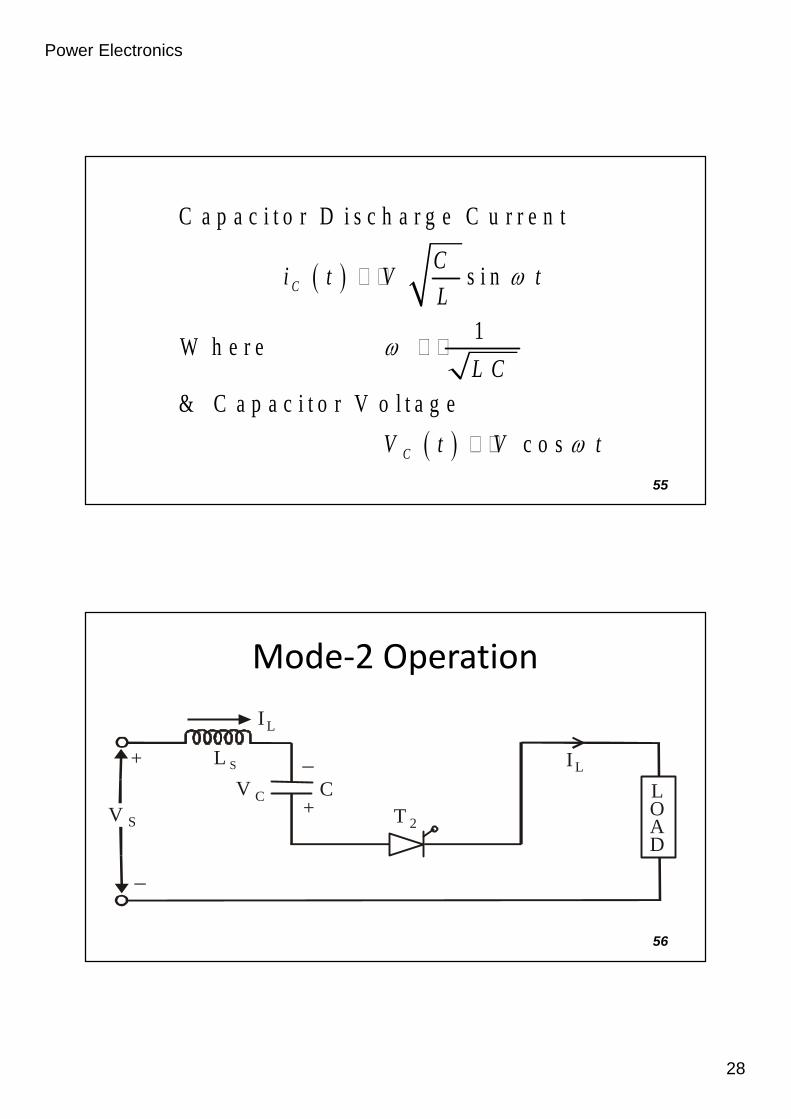
C a p a c i t o r D i s c h a r g e C u r r e n t
s i n
1W h e r e
& C a p a c i t o r V o l t a g e
c o s
C
C
Ci t V t
L
L C
V t V t
Mode-2 Operation
LOAD
C
L S
V S+
_+
_
T 2
V C
I L
I L
56Prof. T.K. Anantha Kumar, E&E Dept., MSRIT

Power Electronics
29
• Thyristor T2 is now fired to commutate thyristor T1.• When T2 is ON capacitor voltage reverse biases T1 and turns if
off.• The capacitor discharges through the load from –V to 0.• Discharge time is known as circuit turn-off time.
57Prof. T.K. Anantha Kumar, E&E Dept., MSRIT
58Prof. T.K. Anantha Kumar, E&E Dept., MSRIT
CC
L
V Ct
I
• Circuit turn-off time is given by:
• Where IL is a load current• tc is depends on load current, it must design for the
worst case condition which occur at the maximumvalue the load current and minimum value of loadvoltage

Power Electronics
30
• Capacitor recharges back to the supply voltage (with plate ‘a’ +ve).• This time is called the recharging time and is given by
• The total time required for the capacitor to discharge and rechargeis called the commutation time and it is given by
• At the end of Mode-2 capacitor has recharged to VS and the freewheeling diode starts conducting.
59Prof. T.K. Anantha Kumar, E&E Dept., MSRIT
Sd
L
V Ct
I
r C dt t t
Mode-3 Operation
LOAD
C
L S
V S
+_
+
_
T 2V S
F W D
IL
IL
60Prof. T.K. Anantha Kumar, E&E Dept., MSRIT

Power Electronics
31
61Prof. T.K. Anantha Kumar, E&E Dept., MSRIT
sinSC S L S
LV t V I t
C
Mode-4 Operation
LOAD
C
L S
V S
+_
+
_
D 1
LF W D
IL
V C
62Prof. T.K. Anantha Kumar, E&E Dept., MSRIT
Power Electronics
32
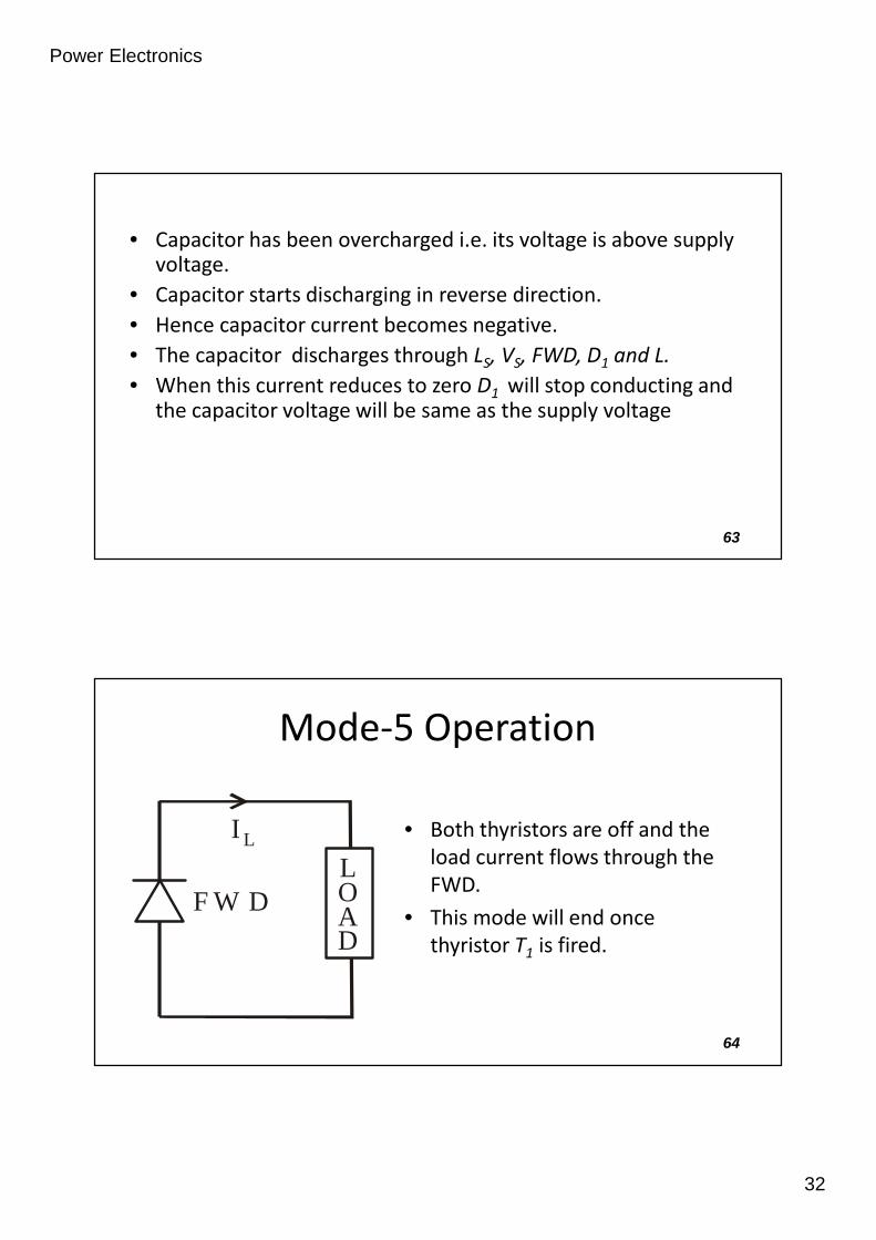
• Capacitor has been overcharged i.e. its voltage is above supplyvoltage.
• Capacitor starts discharging in reverse direction.• Hence capacitor current becomes negative.• The capacitor discharges through LS, VS, FWD, D1 and L.• When this current reduces to zero D1 will stop conducting and
the capacitor voltage will be same as the supply voltage
63Prof. T.K. Anantha Kumar, E&E Dept., MSRIT
Mode-5 Operation
LOAD
I L
F W D
• Both thyristors are off and theload current flows through theFWD.
• This mode will end oncethyristor T1 is fired.
64Prof. T.K. Anantha Kumar, E&E Dept., MSRIT

Power Electronics
33
C a p a c i t o r C u r r e n tI L
t
t
I p C u r r e n t t h r o u g h T 1
i c
0I p
i T 1
0
I L
65Prof. T.K. Anantha Kumar, E&E Dept., MSRIT
t
t
t
V o l t a g e a c r o s s T 1
O u t p u t V o l t a g e
C a p a c i t o r V o l t a g e
t ct d
v T 1
V c
0v o
V s c+ V
V s
v c
V c
- V c
66Prof. T.K. Anantha Kumar, E&E Dept., MSRIT

Power Electronics
34
Disadvantages• A starting circuit is required and the starting circuit should be
such that it triggers thyristor T2 first.• Load voltage jumps to almost twice the supply voltage when
the commutation is initiated.• The discharging and charging time of commutation capacitor
are dependent on the load current and this limits highfrequency operation, especially at low load current.
67Prof. T.K. Anantha Kumar, E&E Dept., MSRIT
• Chopper cannot be tested without connecting load.• Thyristor T1 has to carry load current as well as resonant
current resulting in increasing its peak current rating.
68Prof. T.K. Anantha Kumar, E&E Dept., MSRIT