chinese owner’s manual
TRANSCRIPT

OWNER’S MANUAL
Please read this manual carefully before operatingyour set and retain it for future reference.
P/NO : MFL37115811 www.lg.com
TYPE : POWER DISTRIBUTION INDICATOR MODELS : PQNUD1S00
ENGLIS
HITA
LIANO
ESPAÑOL
FRANÇAIS
DEUTSCH
CHINESE

2 Electricity Distribution Indicator
Power Distribution Indicator Owner's & Installation Manual
TABLE OF CONTENTSFOR YOUR RECORDSWrite the model and serial numbers here:
Model #
Serial #
You can find them on a label on the side of each unit.
Dealer's Name
Date Purchased
■ Staple your receipt to this page in the event you needto prove date of purchase or to issue warranty.
READ THIS MANUALInside you will find many helpful hints on how to useand maintain your Power Distribution Indicator properly.Just a little preventive care on your part can save you agreat deal of time and money over the life of yourPower Distribution Indicator.
You'll find many answers to common problems in thechart of troubleshooting tips. If you review our chart of
Troubleshooting Tips first, you may not need to callfor service at all.
PRECAUTION• Contact the authorized service technician for repair or
maintenance of this unit.• Contact the installer for installation of this unit.• The air conditioner is not intended for use by young
children or invalids without supervision.• Young children should be supervised to ensure that
they do not play with the air conditioner.• When the power cord is to be replaced, replacement
work shall be performed by authorized personnel onlyusing only genuine replacement parts.
• Installation work must be performed in accordance withthe National Electric Code by qualified and authorizedpersonnel only.
Cautions for safety ......................3
Overview ......................................6
Available Watt-hour meter ..........7
Wiring Diagram ............................8
Internal Wiring Diagram ............12
Installation ..................................13
How to set interface unit ...........19
How to set each Indoor Unit .....20
Installation Guide .......................26
Usage ..........................................27

Cautions for safety
Userʼs Manual 3
ENGLIS
H
You should always requestproduct installation to ourService Center or toinstallation expert agency.
Use specified parts. When reinstalling an existinginstalled product, request it toour Service Center or toinstallation expert agency.
• Otherwise it may causefire hazard, electric shock,explosion, injury ordamage.
• Or else it may cause firehazard, electric shock,explosion, injury, damageand trouble failure.
• Otherwise it may cause firehazard, electric shock,explosion, injury or damage.
Donʼt keep or use ignitable gas or any otherflammable material in vicinity of the product.
Donʼt disassemble, repair and modify theproduct at your will.
• Otherwise it may cause fire hazard andproduct trouble failure.
• Or else it may cause fire hazard and electricshock.
Cautions for safetyTo prevent injury to the user or other people and property damage, the following instructions must befollowed.■ Incorrect operation due to ignoring instruction will cause harm or damage. The seriousness is
classified by the following indications.
This symbol indicates the possibility of death or serious injury.
This symbol indicates the possibility of injury or damage to properties only.
■ Meanings of symbols used in this manual are as shown below.
Be sure not to do.
Be sure to follow the instruction.
■ WHEN INSTALLING
SPECIFIEDPARTS
Benzene�
�Ether Thinner

Cautions for safety
4 Electricity Distribution Indicator
Donʼt install it where rain falls on. Donʼt install it in humid place.
• Otherwise it may cause product failure. • Otherwise it may cause product failure.
Donʼt change or extendelectric supply wire at yourwill.
Donʼt let there exist fire heatnear the product.
Donʼt use heat equipmentnear the electricity supplyline.
• Or else it may cause firehazard and electric shock.
• Otherwise it may cause firehazard.
• Or else it may cause firehazard and electric shock.
Donʼt spill water into interiorof the product.
Donʼt put heavy material uponelectricity supply chord.
Donʼt put heavy materialupon the product.
• Otherwise it may causeelectric shock and productfailure.
• Or else it may cause firehazard and electric shock.
• Or else it may causeproduct trouble failure.
Always request to our ServiceCenter or installation expert agencyin such case as the product hasbeen submerged under water.
Child or the old and the weakshall use it under custody ofpatron.
Donʼt give impact to theproduct.
• Or else it may cause firehazard and electric shock.
• Otherwise it may causesafety accident or productfailure.
• If the product is impacted,it may cause producttrouble failure.
■ WHEN USING

Cautions for safety
Userʼs Manual 5
ENGLIS
H
Donʼt clean the product withstrong detergent of solventsbut only use soft cloth.
If water has been smearedon electric charge part, useit after removing water.
Donʼt let metallic productsof necklace, coin, key, watchetc. touch the batteryterminal.
• Or else it may cause firehazard and productdeformation.
• Or else it may causeproduct failure.
• Or else it may cause productfailure and injury.
■ WHEN USING
Wax Thinner

Overview
Overview
6 Electricity Distribution Indicator
■ Functions• Accumulation of total power consumption
• Indication of current power in use
• Indication of accumulated power for period
• Indication of standby power (option setting)
■ Specification• Power Supply: 220~240V AC 50/60HZ 1Ø
• Dimension: 200mm (W) X 120mm (H) X 55mm (D)
• Connectable Units: 1 Outdoor Unit per Electric Power Distribution Indicator.
■ Count Method for Electric Power Distribution• Power Consumption of each Indoor Unit = Power Consumption of Outdoor Unit x [Weighting Power of each
Indoor Unit / Weighting Power of total Indoor Units]
• Weighting Power of each Indoor Unit = Operation (On/Off) x [ Capacity of Indoor Unit X LEV open rate X Fanstep of Indoor Unit ]

Overview
Userʼs Manual 7
1. Indicator LCD Display 2. Name Plate of each room 3. Menu Button 4. Up and Down Button5. Right Shift Button6. SHIFT Button for LCD Screen Change
Available Watt-hour meter(Local purchase)
1
2
3
4
5
6
ENGLIS
H
■ Parts of a PDI
• Use the digital watt meter which send the pulse signal depending on the power consumption.
• Use watt meter of 1W/pulse, 2W/pulse, 4W/pulse, 6W/pulse, 8W/pulse or 10W/pulse or PT/CT Type (pulse width: 40 –400 msec).

Wiring Diagram
8 Electricity Distribution Indicator
Pulse type
PDI
Indoor unit address setup
(00) (01) (02) (03)
Watt meter3Ø 380VAC
AC220V
Multi V (PI485 is embedded at the Outdoor unit)
OUT FAN(A)
OUT FAN(B)
Internet A
Internet B
1Ø 220VAC
Address setup
Start -> End (00) -> (03)
Pulse type
PDI 1Ø 220VAC
MultiV/MultiV PLUS Outdoor unit
Indoor unit address setup
(00) (01) (02) (03)
Watt meter3Ø 380VAC or1Ø 220VAC
PI-485
■ Independent operation of PDI- Connect the product as shown in the below connection diagram
1. MultiV / MultiV PLUS
2. Multi V PLUS2 or 3 series
Wiring Diagram
Wiring Diagram
Userʼs Manual 9
ENGLIS
H
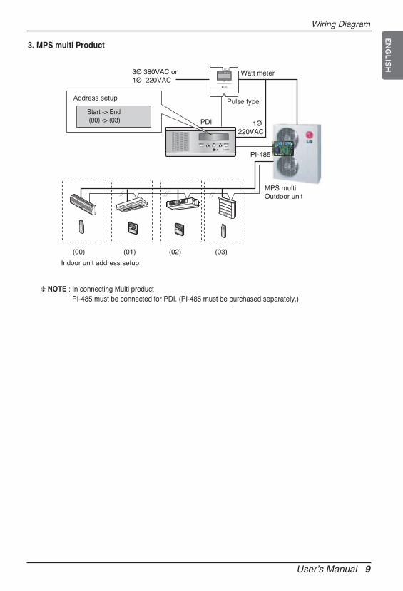
Address setup
Start -> End (00) -> (03)
Pulse type
PDI 1Ø 220VAC
MPS multiOutdoor unit
Indoor unit address setup
(00) (01) (02) (03)
PI-485
Watt meter3Ø 380VAC or1Ø 220VAC
3. MPS multi Product
❈ NOTE : In connecting Multi product PI-485 must be connected for PDI. (PI-485 must be purchased separately.)

Wiring Diagram
10 Electricity Distribution Indicator
■ Operation with PC Central controller or ACP- Connect the product as shown in the below connection diagram.
Address setup
Start -> End (00) -> (03)
Address setup
Start -> End (7C) -> (7F)
PDI
PDI
Multi/ Multi V Outdoor unit
Multi/ Multi V Outdoor unit
Indoor unit address setup
Indoor unit address setup
PI-485
PI-485
Watt meter
SlaveSetting
SlaveSetting
Watt meter
3Ø 380VAC or1Ø 220VAC
(00) (01) (02) (03)
(7C) (7D) (7E) (7F)
ACP ACSMART
OrLAN LAN LALANLANLANLANANLANAAAALANLANLANNLALANLANAANNLANLALANLLAALANLALANLLANANNLAANNNNLLAANNNNLLANLAAAANNLLLAAAANNANLLALLLLLA
❈ NOTEMulti V PLUS 2 or 3series Product does not need PI485 to operate PDI. But, Multi Product must connect PI485to operate PDI. (PI485(PMNFP14A0) must be purchased separately)

Wiring Diagram
Userʼs Manual 11
ENGLIS
H
■ Operation with LG Web PDI (PQCPM11A0)- Connect the product as shown in the below connection diagram.
PDI
PDI
Multi/ Multi V Outdoor unit
Multi/ Multi V Outdoor unit
Indoor unit address setup
Indoor unit address setup
PI-485
PI-485
Watt meter
Watt meter
3Ø 380VAC or1Ø 220VAC
(00) (01) (02) (03)
(7C) (7D) (7E) (7F)
Start -> End(00) -> (03)
Address setup
Start -> End(7C) -> (7F)
Address setup
BMSor
LG-NET 1
MENU/SELECT
TXRX
LG-NET 2TXRX
LG-NET 3TXRX
LG-NET 4TXRX
Ethernet 1ACTLNK
Ethernet 2ACTLNK
Console
Run
Power
TXRX
FDDTXRX
Ext. TXRX
DI12
34
56
78
910
1112
1314
1516
1718
1920
DO12
34
Web PDI
LG-NET 1
MENU/SELECT
TXRX
LG-NET 2TXRX
LG-NET 3TXRX
LG-NET 4TXRX
Ethernet 1ACTLNK
Ethernet 2ACTLNK
Console
Run
Power
TXRX
FDDTXRX
Ext. TXRX
DI12
34
56
78
910
1112
1314
1516
1718
1920
DO12
34
SlaveSetting
SlaveSetting
When PI-485 is off, PDI cannot work.
❈ NOTEMulti V PLUS 2 or 3series Product does not need PI485 to operate PDI. But, Multi Product must connect PI485to operate PDI. (PI485(PMNFP14A0) must be purchased separately)

CN
_WAT
TME
TER
WHITE (-)
BLACK (+)
CN
_PC
+
CN
_OU
TFA
N B A
Power 220~240V/AC
50/60 Hz
Multi V or PI485Watt-hour meter
BUS B BUS A
INT. B INT. A
CN_POWER
Remote Reading Device (Option)
TX : A RX : B +
WHMPDI
Multi VPI-485
...Indoor unit
The color and polarity of the communications line can differ from what’s indicated on the PCB depending on the manufacturer of watt meter. [ Black -> (+), white -> (-) ]
• Turn on the power after connecting the product.
■ Install the product as per the following wiring diagram
Internal Wiring Diagram
Internal Wiring Diagram
12 Electricity Distribution Indicator

Userʼs Manual 13
InstallationENGLIS
H
InstallationHow to set Option
1. You must start the key operation within 10 minutes afterturning on the power for setting options.
2. When you press the Menu and Shift key at the same time,the following option screen will be shown.
• Product selection When the first two digits flash, you can use the ▲ or ▼ key to set the product.
[00] -> Unit (When using in connection with indoor communication Line Of MultiV / MultiV PLUS)
[10] -> Slave (when using in connection with central controller)
[11] -> Master (when not using in connection with central controller)
Ex) Product selection: Master, Watt meter: 1W/1 pulse
1 1 0 0 0 0 0 0 0 M a s t e r 1 W / p
M I C R O N I C N O - S T B P
[11] : Independent operation of PDI
Option setup screen
Initial Screen
Press Menu and Shiftat same time
E L E C T R I C P O W E R
D I S T R I B U T O R
1 1 0 0 0 0 0 0 0 U n i t 1 W / p
M I C R O N I C N O - S T B P
14 Electricity Distribution Indicator
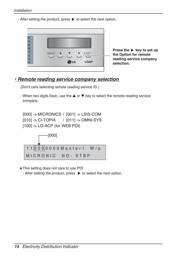
✱ This setting does not care to use PDI - After setting the product, press ▶ to select the next option.
• Remote reading service company selection (Don't care selecting remote reading service ID.)
- When two digits flash, use the ▲ or ▼ key to select the remote reading servicecompany.
1 1 0 0 0 0 0 0 0 M a s t e r 1 W / p
M I C R O N I C N O - S T B P
[000] -> MICRONICS / [001] -> LSIS-COM[010] -> CI-TOPIA / [011] -> OMNI-SYS[100] -> LG-ACP (for WEB PDI)
[000]
Installation
- After setting the product, press ▶ to select the next option.
LGAP
Press the ▶ key to set upthe Option for remotereading service companyselection.

Userʼs Manual 15
ENGLIS
HInstallation
- After setting the product, press ▶ to select the next option.
LGAP
Press the ▶ key to set upthe option for watt meterselection.
- After setting the product, press ▶ to select the next option.
• Watt meter selection- When the third 3 digits flash, use the ▲ or ▼ key to select the meter constant of the
watt meter.
Ex) Product selection: Master, watt meter: 2W/ pulse
[001] is set to 2W/pulse and shows the meter constant of the watt-hour meter.
1 1 0 0 0 0 0 1 0 M a s t e r 2 W / p
M I C R O N I C N O - S T B P
[000] -> 1 wh/ Pluse / [001] -> 2 wh/ Pluse[010] -> 4 wh/ Pluse / [011] -> 6 wh/ Pluse[100] -> 8 wh/ Pluse / [101] -> 10 wh/ Pluse[110] - > PT/CT : In case of CT using.
After setting value of CT & watt-hour meter, press ‘SHIFT’ key.
I n p u t I n [P u l s e / k W h ]
C T : 0 0 0 2 0 / P r : 0 2 5 0 0
After setting PT/CT(110),press ‘SHIFT’ key.
1 1 0 0 0 1 1 0 0 M a s t e r PT/CT
M I C R O N I C N O - S T B P
Ex) In case of CT (Current Transformer) using.- CT ratio 20 : 1- Watt-hour meter : 2500 Pulse/kWh
When the first digit flashes, use the ▶ key to shift cursor right.And you can use the ▲ or ▼ key to set value of CT & watt-hour meter.

16 Electricity Distribution Indicator
✱ What is standby power selection function?: Standby power refers to the electric power consumed by the product after theoperation of the product is turned off. It is the function of separately saving the power consumed when all heating andair conditioning indoor units are turned off.
• Standby power indication selection- When the forth digit flashes, use the ▲ or ▼ key to select the standby power.
[0] NO-STBP -> Does not show the standby power[1] CAL-STEP -> Shows the standby power
• Note : If the PDI has been set Slave in previous option selection then Certainly SetNO-STBP
Ex) Product selection: Master, standby power indication selection
1 1 0 0 0 0 0 0 1 M a s t e r 1 W / p
M I C R O N I C C A L - S T B P
[1] is set to CAL-STBP and shows you the standby power.
LGAP
Press the ▶ key to selectthe option for standbypower.
Installation

Userʼs Manual 17
ENGLIS
HInstallation
✱ When setting the remote reading service ID, enter the remote reading service IDassigned by the remote reading service company.
3. After setting the option, press the Shift key to enter theremote reading service ID setup mode.(In case of selecting reading service ID in )• This function is applicable to only korean marcket (Domestic)
So, skip this setting in the procedure for overseas marcket Press the "SHIFT" key
- When the first two digits flash, use the s or t key to select the remote reading service ID by company.
4. After entering the remote reading service ID, press the Shiftkey to enter the indoor address selection mode.(In case of the selecting "Master/Slave")
OMNI SYS ID setup
OUT DR ID(CITOPIA)XX
CI-TOPIA ID setup
OUT DR ID(MICRONIC)XX
MICRONICS ID setup
LS lS ID setup
OUT DR ID(LSIS)XXXX
OUT DR ID(OMNI-SYS)XXXX
LG Web PDI setup
OUT DR ID(LG-ACP)XXXX
LGAP

18 Electricity Distribution Indicator
Press the Shift key to enter theindoor selection mode
Initial Screen
LGAP
( S t a r t ) - > ( E n d )
( 0 0 ) - > ( 0 0 )
( S t a r t ) - > ( E n d )
( 0 0 ) - > ( 3 F )
( S t a r t ) - > ( E n d )
( 1 2 ) - > ( 1 5 )
• You can select the option for indoor address selection mode only when Master / Slave is selected.
• You can distribute the using power to maximum of 64 indoor units. (When showing the stand by power, maximum of 63 indoor units.)
Installation
- If the PDI connects to 64 indoor units, set the addresses of indoor units from 00 to 3F.(Central control address : 00~3F)
Ex) If addresses of indoor units are set by “12”, “13”, “14” and “15”, set start address by “12” and set end address by “15”.
- Press the Menu key to save the remote reading service ID and return to theinitial screen.

Userʼs Manual 19
ENGLIS
HInstallation
How to set Interface unit
ON
L1 2 3 4
KSDO4H
Select Air Conditioer Type
Select Network Type
Select Advanced Control Type
Multi V & Multi(LGAP applied) products Configuration Methods
CAUTION
The wrong setting of air-conditioner switch could cause malfunctioning.Switch setting must be done carefully.Push the Reset button after changing the Dip switch.
NOTE : Multi(Non-Inverter) Product applied Common PCBPCB P/NO. : 6871A20917*P/NO. : 6871A20918*P/NO. : 6871A20910*
PI-485
ON
ON
ON
ON
ON
➔ 1 ON, All others OFF: Multi V products(Except CRUN products) or Multi(Non-Inverter) Product applied Common PCB(Refer to NOTE) orMulti(Inverter) Product + Central Controller(All types) - Without LGAP
➔ 1 and 4 ON, All others OFF: Multi V products(Except CRUN products) orMulti(Non-Inverter) Product applied Common PCB or Multi(Inverter) Product +Central Controller(All types) - Using LGAP
➔ 2 ON, All others OFF: Multi(Non-Inverter) Product + Centroller(All types) - Without LGAP
➔ 2 and 4 ON, All others OFF: Multi Non-Inverter Product + Central Controller(All Types) - Using LGAP
➔ 1,2,3,4 ON : Multi V CRUN Product + Central Controller(All types) - Using LGAP
• Please refer the corresponding Central Controller installation manual if you want to knowwhether your Central Controller is compatible with LGAP or not.

20 Electricity Distribution Indicator
How to set each Indoor Unit■ Using wired remote controller
Timer Cancel
Program Week
Hour Min
Holiday
Set/Clr
RESET
ZONE 1 2 3 4Operation unit
HumidifyJET
AUTO
AUTO SWING OPERATION FAN SPEED
Program set
SUB FUNCTIONSET TEMPRoom Temp
HIMEDLO
HeaterDefrostFilter
Preheat
Out doorTime
TimerOnSet no. Time
Off01 03 05 07 09 11 13 15 17 19 21 23
Plasma
Group No. Indoor No.
3 AProgram
Set/Clr
3. Press the "Program" & "Setup/Clr" keys at the same timefor 3 seconds to set up the indoor address.• The room address on the PDI is listed in the ascending order of indoor number.
Ex) If the indoor addresses are "7C", "7D", "7E" and "7F", the order of the indoor unit on thePDI are "1", "2", "3" and "4".
• The indoor numbers must be entered in sequence to be accurately recognized in the PDI.Ex) Correct indoor unit address setup: "01", "02", "03" (setup in order)
Incorrect indoor unit address setup: "01", "02", "06"
1. Press the "Program" &"Set/Clr" keys at the sametime.
2. Set up the indoor addressusing the temperatureadjustment key☛ Setup range: 00-7F
How to set Interface unit

How to set each Indoor Unit
Userʼs Manual 21
ENGLIS
H
Function Code
Group NoIndoor No.
Set Group No. by pressing button.(0~F)3
Move to Indoor No. setting option by pressing button.4
Set Indoor No. by pressing button.5
Press button to save.6
Pressing button will exit settings mode.❈ After setup, it automatically gets out of
setup mode if there is no button input for 25 seconds.
❈ When exiting without pressing set button, the manipulated value is not reflected.
7
If entering into address setup mode by using button, it indicates as picture below.2
If pressing button long for 3 seconds, it enters into remote controller setter setup mode.- If pressing once shortly, it enters
into user setup mode. Please press more than 3 seconds for sure.
1

How to set each Indoor Unit
22 Electricity Distribution Indicator
Function Code Group No
Indoor No.
Press the button for 4 seconds to enter the installer setting mode until timer segment display "01:01".
1
Set Group No. by pressing button.3
Move to Indoor No. setting option by pressing button.4
Set Indoor No. by pressing button.5
Press button to save or release. 6
Press button to exit or system will automatically exit after 25 seconds without any input.
7
Repeat pressing button to select Function code 02.
Ex) Setting Address as 'F5'
2

How to set each Indoor Unit
Userʼs Manual 23
ENGLIS
H
■ Using wireless remote controller
ON OFF
SET CANCEL
PLASMA
Addresssetting
Addresscheck
1. Address setting mode1) With the top left key pressed, press the Reset button.
(Press the left key for more than 3 second)
2) Using the temperature adjustment key, set up the indoor unitaddress
❉ Setup range: 00-7F
ex)
3) After setting the address, press the On/Off key oncedirecting the remote controller to the indoor unit.
4) When indoor unit shows the setting address, the addresssetup is complete.(The time and method of the address display can differdepending on the indoor unit type.)
5) Reset the remote controller and use it.
3
A
• No use For Power Distribution Indicator• Used for Central Control settings
2. Address check mode1) With the top right key pressed, press the Reset button.
(Press the left key for more than 3 seconds.)
2) Press the On/Off key once directing the remote controller to the indoor unit.The indoor unit shows the setting address and the address setup is completed.(The time and method of the address display can differ depending on the indoor unit type.)
3) Reset the remote controller and use it
❉ Depending on the manufactured date of the wired/ wireless remote controller, the abovefunction might not work.Since this is a function not relevant for consumer in using the product, setup the remotecontroller to enable address setup during installation.
❉ When setting the address, refer to the details on the previous page.

How to set each Indoor Unit
24 Electricity Distribution Indicator
ON OFF
CANCEL
AUTO CLEANSET
(00, ...., 90, A0, ...., F0)
(00, ...., 09, 0A, ...., 0F)
(Address No.3 indoor-unit of Second Group)
To lower the temperature
To raise the temperature
When RESET button is pressed once with JET COOL buttonheld, ʼ00ʼ will be shown on the LCD DISPLAY and itʼll enterinto the address set mode.
1
Whenever you press the Temperature Increase(UP) button,the group address number also increases.(Left-digit) And whenever you press the Temperature Decrease(DOWN)button, the indoor-unit address number also increases.(Right-digit) (Control scope of Group Address No. and Indoor-unit Address No. : 00~FF)
2
When you press the START/STOP button on your remote-controller directed toward the receiver of indoor-unit aftersetting address, the address would be set.
3
When you press RESET button after completing addresssetup, the address setup function will be cancelled.In the state of cancellation, LCD display shows the initialstandby mode.
4
❏ You are recommended to follow below procedure to check indoor-unit address with remote-controller.Press RESET button once with the wind direction button( ) of remote-controller held.The LCD DISPLAY on remote-controller shows ʼ88ʼ. When you press START/STOP buttonon your remote-controller directed toward the receiver of indoor-unit at this time, the displayLED of indoor-unit lights at the initial set address.
NOTICE

How to set each Indoor Unit
Userʼs Manual 25
ENGLIS
H
Installer Setting - Checking Address of Central Control
With the MODE button pressed, press the RESET button.1
With the PLASMA button pressed, press the RESET button.1
Press the ON/OFF button toward the indoor unit 1 time, and the indoor unit will display the setaddress in the display window.
- The address display time and method can differ by the indoor unit type.
2
Reset the remote controller to use the general operation mode.3
By using the TEMPERATURE SETTING button, set the indoor unit address.- Setting range : 00 ~ FF2
After setting the address, press the ON/OFF button toward theindoor unit 1 time.3
The indoor unit will display the set address to complete the address setting.- The address display time and method can differ by the indoor uint type.
Reset the remote controller to use the general operation mode.
45
Group No.
Indoor Unit No.

Installation Guide
26 Electricity Distribution Indicator
Power Distribution Indicator and WHM should be installed in the specified cabinet which can protect thePower Distribution Indicator from water and humidity.
✱ NOTE : WHM (Watt-hour meter)
• Suppl power after completing the Wiring• Set the Power Distribution Indicator so as to fit the usage condition.
Installation Guide
EX1) EX2)
EX3) EX4)

Usage
Userʼs Manual 27
ENGLIS
H
(The distributed power consumption is based on current operating condition)
• Press the Menu key once to display the current power consumption.
• Consecutively press the Menu key to switch the screen.
• The PDI will operate normally after 3 minutes, when all options are set .
1. PWR distribution mode
Usage
Press “Menu” key
Press “Menu” key
Press “Menu” key
PWR Distribution Display Mode
Accumulated PWR Display Mode
Period Accumulated PWR Display Mode
Initial Mode
Pre
ss “
Men
u” k
ey
Press Shift key Indoor 1 Value
LGAP
P W R
X X ) X X X X . X X X ) X X X X . X
D i s t ( 0 1 ) X X X X . X
Total SUM Value
P W R
X X ) X X X X . X X X ) X X X X . X
D i s t ( 0 2 ) X X X X . X
Total SUM Value
Indoor 2 Value
Indoor 3 Value Indoor 4 Value
LGAP
• It displays the current power consumption of each indoor unit(Watt/hour)
• When 1-2 indoor units are connected, only 1 page is displayed.
• When 4 or more indoor units are connected, press the "Shift" key to check the next page.

Usage
28 Electricity Distribution Indicator
• When selecting the option for classifying the stand by power, the stand by power is displayed in the lastpage.
• When selecting the option for classifying the stand by power, the stand by power is displayed in the lastpage.
2. ACCUMPWR distribution mode• It displays the accumulated power consumption of each indoor unit (Kwh)
• When 1-2 indoor units are connected, only 1 page is displayed.
• When 4 or more indoor units are connected, press the Shift key to check the next page.
Press Shift key Indoor 1 Value
A C C
X X ) X X X X X . X X X ) X X X X X . X
P W R ( 0 1 ) X X X X X . X
Total SUM Value
A C C
X X ) X X X X . X X X ) X X X X X . X
P W R ( 0 2 ) X X X X X . X
Total SUM Value
Indoor 2 Value
P W R
S T B P : 0 0 0 0 . 0
D i s t ( 0 0 ) 0 0 0 0 . 0
The stand by power page
The stand by power page
Indoor 3 Value Indoor 4 Value
A C C
S T B P : 0 0 0 0 . 0
P W R ( 0 0 ) 0 0 0 0 . 0
Stand by power
Stand by power

Usage
Userʼs Manual 29
ENGLIS
H
3. Period accumulated power distribution mode• It displays the power consumption of each indoor unit (Kwh)
• When 1-2 indoor units are connected, only 1 page is displayed.
• When 4 or more indoor units are connected, press the Shift key to check the next page.
• Press the ▲ and ▼ key at the same time for 3 seconds to clear the data.• As the function for manual check, when cleared after the check, it displays the
cumulated power from the clearing point. • When classifying the stand by power, it is shown after the last page.
Press Shift key Indoor 1 Value
P e r i d
X X ) X X X X . X X X ) X X X X . X
A C C M ( 0 1 ) X X X X . X
Total SUM Value
P e r i d
X X ) X X X X . X X X ) X X X X X . X
A C C M ( 0 2 ) X X X X . X
Total SUM Value
Indoor 2 Value
The stand by power indication page
Indoor 3 Value Indoor 4 Value
P e r i d
S T B P : 0 0 0 0 . 0
A C C M ( 0 0 ) 0 0 0 0 . 0
Stand by power

30 Electricity Distribution Indicator
