chiller and cooling tower...
TRANSCRIPT
DELAWARE TECHNICAL COMMUNITY COLLEGE
SPECIFICATIONS FOR
CHILLER AND COOLING TOWER
REPLACEMENT
AT
TERRY BUILDING 100 CAMPUS DRIVE
DOVER, DELAWARE, 19904
PREPARED BY
ISSUED FOR BID NOVEMBER 2019
DEDC PROJECT # 19P263
CHILLER AND COOLING TOWER REPLACEMENT TERRY BUILDING OCTOBER 2019
PROJECT TITLE PAGE DEDC, LLC 00 01 01 – 2 19P263
THIS PAGE INTENTIONALLY LEFT BLANK

TERRY BUILDING CHILLER AND COOLING TOWER REPLACEMENT OCTOBER 2019
DEDC, LLC TABLE OF CONTENTS 19P263 00 01 10 - 1
SECTION 00 01 10
TABLE OF CONTENTS A. Specifications for this project are arranged in accordance with the Construction Specification Institute
numbering system and format. Section numbering is discontinuous and all numbers not appearing in the Table of Contents are not used for this Project.
B. DOCUMENTS BOUND HEREWITH DIVISION 00 - PROCUREMENT AND CONTRACT REQUIREMENTS INTRODUCTORY INFORMATION 00 01 01 - PROJECT TITLE PAGE
00 01 10 - TABLE OF CONTENTS
00 01 15 - LIST OF DRAWING SHEETS
00 11 16 - INVITATION TO BID
PROCUREMENT REQUIREMENTS 00 21 13 - INSTRUCTIONS TO BIDDERS
00 41 13 - BID FORM
00 43 13 - BID BOND
CONTRACTING REQUIREMENTS 00 52 13 - STANDARD FORM OF AGREEMENT BETWEEN OWNER AND CONTRACTOR
(SAMPLE AIA A101)
00 54 13 - AMENDMENT TO AGREEMENT BETWEEN OWNER & CONTRACTOR A101-2017
00 61 13.13 - PERFORMANCE BOND
00 61 13.16 - PAYMENT BOND
006276 - APPLICATION AND CERTIFICATE FOR PAYMENT FORMS
(SAMPLE AIA G702(1992) & G703(1992))
00 63 73 - ALLOWANCE AUTHORIZATION
00 65 00 – CLOSEOUT FORM
(SAMPLE AIA G704-2017)
(SAMPLE AIA G706-1994)
(SAMPLE AIA G706A-1994)
(SAMPLE AIA G707-1994)
00 72 13 - GENERAL CONDITIONS TO THE CONTRACT
(SAMPLE AIA A201)
00 73 13 - SUPPLEMENTARY GENERAL CONDITIONS

CHILLER AND COOLING TOWER REPLACEMENT TERRY BUILDING OCTOBER 2019
TABLE OF CONTENTS DEDC, LLC 00 01 10 - 2 19P263
00 73 46 - WAGE RATE DETERMINATION SCHEDULE
00 81 13 - GENERAL REQUIREMENTS
00 81 14 - EMPLOYEE DRUG TESTING REPORT FORM
DIVISION 01 - GENERAL REQUIREMENTS
01 10 00 SUMMARY 01 20 00 PRICE AND PAYMENT PROCEDURES 01 21 00 ALLOWANCES 01 23 00 ALTERNATES 01 30 00 ADMINISTRATIVE REQUIREMENTS 01 40 00 QUALITY REQUIREMENTS 01 50 00 TEMPORARY FACILITIES AND CONTROLS 01 60 00 PRODUCT REQUIREMENTS 01 70 00 EXECUTION AND CLOSEOUT REQUIREMENTS 01 74 19 CONSTRUCTION WASTE MANAGEMENT 01 78 00 CLOSEOUT SUBMITTALS 01 79 00 DEMONSTRATION AND TRAINING 01 91 13 GENERAL COMMISSIONING REQUIREMENTS DIVISION 03 - CONCRETE 03 30 00 CAST-IN-PLACE CONCRETE DIVISION 22 - PLUMBING 22 07 19 PLUMBING PIPING INSULATION 22 10 05 PLUMBING PIPING DIVISION 23 - HEATING, VENTILATING, AND AIR-CONDITIONING (HVAC)
23 05 13 COMMON MOTOR REQUIREMENTS FOR HVAC EQUIPMENT 23 05 19 METERS AND GAGES FOR HVAC PIPING 23 05 48 VIBRATION AND SEISMIC CONTROLS FOR HVAC PIPING AND
EQUIPMENT
23 05 53 IDENTIFICATION FOR HVAC PIPING AND EQUIPMENT 23 05 93 TESTING, ADJUSTING, AND BALANCING FOR HVAC 23 07 19 HVAC PIPING INSULATION 23 09 69 VARIABLE FREQUENCY CONTROLLERS 23 21 13 HYDRONIC PIPING 23 21 14 HYDRONIC SPECIALTIES 23 21 23 HYDRONIC PUMPS 23 25 00 HVAC WATER TREATMENT 23 64 12 LARGE AIR COOLED CHILLERS DIVISION 26 - ELECTRICAL 26 05 05 SELECTIVE DEMOLITION FOR ELECTRICAL 26 05 19 LOW-VOLTAGE ELECTRICAL POWER CONDUCTORS AND
CABLES
26 05 26 GROUNDING AND BONDING 26 05 29 HANGERS AND SUPPORTS 26 05 33.13 CONDUIT FOR ELECTRICAL SYSTEMS

TERRY BUILDING CHILLER AND COOLING TOWER REPLACEMENT OCTOBER 2019
DEDC, LLC TABLE OF CONTENTS 19P263 00 01 10 - 3
26 05 33.16 BOXES FOR ELECTRICAL SYSTEMS 26 05 53 IDENTIFICATION FOR ELECTRICAL SYSTEMS 26 05 83 WIRING CONNECTIONS 26 24 16 PANELBOARDS 26 27 26 WIRING DEVICES 26 28 16.13 ENCLOSED CIRCUIT BREAKERS
END OF SECTION

CHILLER AND COOLING TOWER REPLACEMENT TERRY BUILDING OCTOBER 2019
TABLE OF CONTENTS DEDC, LLC 00 01 10 - 4 19P263
THIS PAGE INTENTIONALLY LEFT BLANK
TERRY BUILDING CHILLER AND COOLING TOWER REPLACEMENT OCTOBER 2019
DEDC, LLC LIST OF DRAWING SHEETS 19P263 00 01 15 - 1
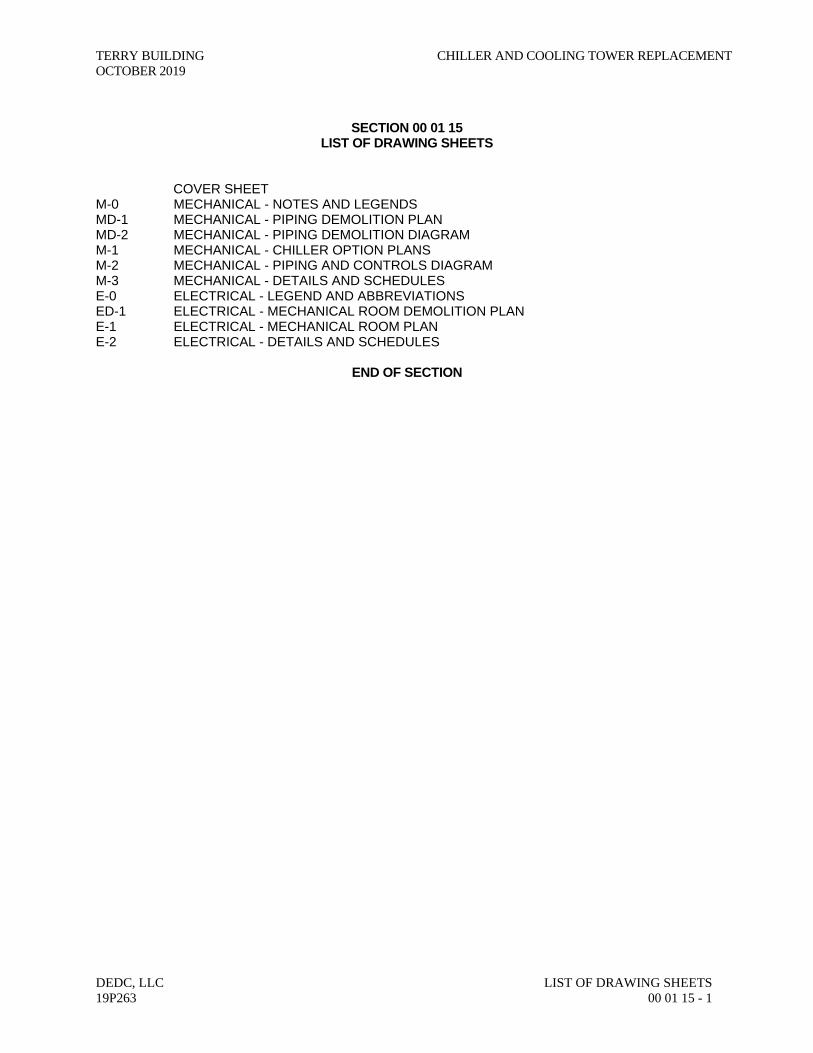
SECTION 00 01 15
LIST OF DRAWING SHEETS COVER SHEET M-0 MECHANICAL - NOTES AND LEGENDS MD-1 MECHANICAL - PIPING DEMOLITION PLAN MD-2 MECHANICAL - PIPING DEMOLITION DIAGRAM M-1 MECHANICAL - CHILLER OPTION PLANS M-2 MECHANICAL - PIPING AND CONTROLS DIAGRAM M-3 MECHANICAL - DETAILS AND SCHEDULES E-0 ELECTRICAL - LEGEND AND ABBREVIATIONS ED-1 ELECTRICAL - MECHANICAL ROOM DEMOLITION PLAN E-1 ELECTRICAL - MECHANICAL ROOM PLAN E-2 ELECTRICAL - DETAILS AND SCHEDULES
END OF SECTION

CHILLER AND COOLING TOWER REPLACEMENT TERRY BUILDING OCTOBER 2019
LIST OF DRAWING SHEETS DEDC, LLC 00 01 15 - 2 19P263
THIS PAGE INTENTIONALLY LEFT BLANK
TERRY BUILDING CHILLER AND COLING TOWER REPLACEMENT OCTOBER 2019
DEDC, LLC INVITATION TO BID 19P263 00 11 16 - 1
SECTION 00 11 16 INVITATION TO BID
Sealed bids for Delaware Technical Community College Contract No. DTCC C900406SSC, will be received by DTCC at the Corporate Training Center, Building 400, Chabot Center, Room 401, Delaware Technical Community College, Terry Campus, 100 Campus Drive, Dover, DE 19904 – until 2:00 PM local time on November 21, 2019 at which time they will be publicly opened and read aloud. Bidder bears the risk of late delivery. Any bids received after the stated time will be returned unopened. Project involves the replacement of the existing chiller and cooling tower serving the Terry Building located at the Delaware Technical and Community College, Terry Campus, located in Dover, Delaware. Contract documents may be obtained at the office of DEDC, LLC, 315 S. Chapel Street, Newark, DE 19711, phone (302) 738-7172. Copies of the Bid Documents will be available for examination and order after 10:00 AM local time, on November 6th, 2019. Full sets and partial sets of Bid Documents are available directly from DEDC. LLC, 315 S. Chapel Street, Newark, Delaware 19711 at no charge. Addenda will be issued electronically and only to bidders or subcontractors who obtained full sets of the Bid Documents. Owner and Architect are not responsible for bidders and/or subcontractors not obtaining the information provided through the full set of bid documents. A Pre-Bid Meeting will be held in DTCC at the Education and Technology Building, Room 721, Delaware Technical and Community College, Terry Campus, 100 Campus Drive, Dover, DE 19904 on November 6, 2019 at 10:00 AM local time for the purpose of establishing the listing of subcontractors and to answer questions. ATTENDANCE OF THIS MEETING IS NOT MANDATORY BUT STRONGLY RECOMMENDED. Sealed bids shall be addressed to the Delaware Technical Community College. The outer envelope should clearly indicate: "DTCC CONTRACT NO. C900406SSC - TERRY CAMPUS - TERRY BUILDING CHILLER AND COOLING TOWER REPLACEMENT - SEALED BID - DO NOT OPEN." Bidders will not be subject to discrimination on the basis of race, creed, color, sex, sexual orientation, gender identity or national origin in consideration of this award, and Minority Business Enterprises, Disadvantaged Business Enterprises, Women-Owned Business Enterprises and Veteran-Owned Business Enterprises will be afforded full opportunity to submit bids on this contract. Each bid must be accompanied by a bid security equivalent to ten percent of the bid amount and all additive alternates. The successful bidder must post a performance bond and payment bond in a sum equal to 100 percent of the contract price upon execution of the contract. The Owner reserves the right to reject any or all bids and to waive any informalities therein. The Owner may extend the time and place for the opening of the bids from that described in the advertisement, with not less than two calendar days notice by certified delivery, facsimile machine or other electronic means to those bidders receiving plans.
END OF SECTION

CHILLER AND COLING TOWER REPLACEMENT TERRY BUILDING OCTOBER 2019
INVITATION TO BID DEDC, LLC 00 11 16 - 2 19P263
THIS PAGE INTENTIONALLY LEFT BLANK
TERRY BUILDING CHILLER AND COOLING TOWER REPLACEMENT OCTOBER 2019
DEDC, LLC INSTRUCTIONS TO BIDDERS 19P263 00 21 13 - 1
SECTION 00 21 13 INSTRUCTIONS TO BIDDERS
TABLE OF ARTICLES 1. DEFINITIONS 2. BIDDER’S REPRESENTATION 3. BIDDING DOCUMENTS 4. BIDDING PROCEDURES 5. CONSIDERATION OF BIDS 6. POST-BID INFORMATION 7. PERFORMANCE BOND AND PAYMENT BOND 8. FORM OF AGREEMENT BETWEEN OWNER AND CONTRACTOR ARTICLE 1: GENERAL 1.1 DEFINITIONS 1.1.1 Whenever the following terms are used, their intent and meaning shall be interpreted as
follows: 1.2 DTCC: Delaware Technical Community College 1.3 AGENCY: Contracting Agency as noted on cover sheet. 1.4 DESIGNATED OFFICIAL: The agent authorized to act for the Agency. 1.5 BIDDING DOCUMENTS: Bidding Documents include the Bidding Requirements and the
proposed Contract Documents. The Bidding Requirements consist of the Advertisement for Bid, Invitation to Bid, Instructions to Bidders, Supplementary Instructions to Bidders (if any),

CHILLER AND COOLING TOWER REPLACEMENT TERRY BUILDING OCTOBER 2019
INSTRUCTIONS TO BIDDERS DEDC, LLC 00 21 13 - 2 19P263
General Conditions, Supplementary General Conditions, General Requirements, Special Provisions (if any), the Bid Form (including the Non-collusion Statement), and other sample bidding and contract forms. The proposed Contract Documents consist of the form of Agreement between the Owner and Contractor, as well as the Drawings, Specifications (Project Manual) and all Addenda issued prior to execution of the Contract.
1.6 CONTRACT DOCUMENTS: The Contract Documents consist of the, Instructions to
Bidders, Supplementary Instructions to Bidders (if any), General Conditions, Supplementary General Conditions, General Requirements, Special Provisions (if any), the form of agreement between the Owner and the Contractor, Drawings (if any), Specifications (Project Manual), and all addenda.
1.7 AGREEMENT: The form of the Agreement shall be AIA Document A101, Standard Form of
Agreement between Owner and Contractor where the basis of payment is a STIPULATED SUM. In the case of conflict between the instructions contained therein and the General Requirements herein, these General Requirements shall prevail.
1.8 GENERAL REQUIREMENTS (or CONDITIONS): General Requirements (or conditions) are
instructions pertaining to the Bidding Documents and to contracts in general. They contain, in summary, requirements of laws of the State; policies of the Agency and instructions to bidders.
1.9 SPECIAL PROVISIONS: Special Provisions are specific conditions or requirements peculiar
to the bidding documents and to the contract under consideration and are supplemental to the General Requirements. Should the Special Provisions conflict with the General Requirements, the Special Provisions shall prevail.
1.10 ADDENDA: Written or graphic instruments issued by the Owner/Architect prior to the
execution of the contract which modify or interpret the Bidding Documents by additions, deletions, clarifications or corrections.
1.11 BIDDER OR VENDOR: A person or entity who formally submits a Bid for the material or
Work contemplated, acting directly or through a duly authorized representative who meets the requirements set forth in the Bidding Documents.
1.12 SUB-BIDDER: A person or entity who submits a Bid to a Bidder for materials or labor, or
both for a portion of the Work. 1.13 BID: A complete and properly executed proposal to do the Work for the sums stipulated
therein, submitted in accordance with the Bidding Documents. 1.14 BASE BID: The sum stated in the Bid for which the Bidder offers to perform the Work
described in the Bidding Documents as the base, to which Work may be added or from which Work may be deleted for sums stated in Alternate Bids (if any are required to be stated in the bid).
1.15 ALTERNATE BID (or ALTERNATE): An amount stated in the Bid, where applicable, to be
added to or deducted from the amount of the Base Bid if the corresponding change in the Work, as described in the Bidding Documents is accepted.
1.16 UNIT PRICE: An amount stated in the Bid, where applicable, as a price per unit of
measurement for materials, equipment or services or a portion of the Work as described in the Bidding Documents.
1.17 SURETY: The corporate body which is bound with and for the Contract, or which is liable,
and which engages to be responsible for the Contractor's payments of all debts pertaining to and for his acceptable performance of the Work for which he has contracted.

TERRY BUILDING CHILLER AND COOLING TOWER REPLACEMENT OCTOBER 2019
DEDC, LLC INSTRUCTIONS TO BIDDERS 19P263 00 21 13 - 3
1.18 BIDDER'S DEPOSIT: The security designated in the Bid to be furnished by the Bidder as a
guaranty of good faith to enter into a contract with the Agency if the Work to be performed or the material or equipment to be furnished is awarded to him.
1.19 CONTRACT: The written agreement covering the furnishing and delivery of material or work
to be performed. 1.20 CONTRACTOR: Any individual, firm or corporation with whom a contract is made by the
Agency. 1.21 SUBCONTRACTOR: An individual, partnership or corporation which has a direct contract
with a contractor to furnish labor and materials at the job site, or to perform construction labor and furnish material in connection with such labor at the job site.
1.22 CONTRACT BOND: The approved form of security furnished by the contractor and his
surety as a guaranty of good faith on the part of the contractor to execute the work in accordance with the terms of the contract.
ARTICLE 2: BIDDER'S REPRESENTATIONS 2.1 PRE-BID MEETING 2.1.1 A pre-bid meeting for this project will be held at the time and place designated. Attendance
at this meeting is a pre-requisite for submitting a Bid, unless this requirement is specifically waived elsewhere in the Bid Documents.
2.2 By submitting a Bid, the Bidder represents that: 2.2.1 The Bidder has read and understands the Bidding Documents and that the Bid is made in
accordance therewith. 2.2.2 The Bidder has visited the site, become familiar with existing conditions under which the
Work is to be performed, and has correlated the Bidder’s his personal observations with the requirements of the proposed Contract Documents.
2.2.3 The Bid is based upon the materials, equipment, and systems required by the Bidding
Documents without exception. 2.3 JOINT VENTURE REQUIREMENTS 2.3.1 For Public Works Contracts, each Joint Venturer shall be qualified and capable to complete
the Work with their own forces. 2.3.2 Included with the Bid submission, and as a requirement to bid, a copy of the executed Joint
Venture Agreement shall be submitted and signed by all Joint Venturers involved. 2.3.3 All required Bid Bonds, Performance Bonds, Material and Labor Payment Bonds must be
executed by both Joint Venturers and be placed in both of their names. 2.3.4 All required insurance certificates shall name both Joint Venturers. 2.3.5 Both Joint Venturers shall sign the Bid Form and shall submit a copy of a valid Delaware
Business License with their Bid. 2.3.6 Both Joint Venturers shall include their Federal E.I. Number with the Bid.

CHILLER AND COOLING TOWER REPLACEMENT TERRY BUILDING OCTOBER 2019
INSTRUCTIONS TO BIDDERS DEDC, LLC 00 21 13 - 4 19P263
2.3.7 In the event of a mandatory Pre-bid Meeting, each Joint Venturer shall have a representative
in attendance. 2.3.8 Due to exceptional circumstances and for good cause shown, one or more of these
provisions may be waived at the discretion of the DTCC. 2.4 ASSIGNMENT OF ANTITRUST CLAIMS 2.4.1 As consideration for the award and execution by the Owner of this contract, the Contractor
hereby grants, conveys, sells, assigns and transfers to DTCC of all of its right, title and interests in and to all known or unknown causes of action it presently has or may now or hereafter acquire under the antitrust laws of the United States and DTCC, relating to the particular goods or services purchased or acquired by the Owner pursuant to this contract.
ARTICLE 3: BIDDING DOCUMENTS 3.1 COPIES OF BID DOCUMENTS 3.1.1 Bidders may obtain complete sets of the Bidding Documents from the
Architectural/Engineering firm designated in the Advertisement or Invitation to Bid in the number and for the deposit sum, if any, stated therein.
3.1.2 Bidders shall use complete sets of Bidding Documents for preparation of Bids. The issuing
Agency nor the Architect assumes no responsibility for errors or misinterpretations resulting from the use of incomplete sets of Bidding Documents.
3.1.3 Any errors, inconsistencies or omissions discovered shall be reported to the Architect
immediately. 3.1.4 The Agency and Architect may make copies of the Bidding Documents available on the
above terms for the purpose of obtaining Bids on the Work. No license or grant of use is conferred by issuance of copies of the Bidding Documents.
3.2 INTERPRETATION OR CORRECTION OF BIDDING DOCUMENTS 3.2.1 The Bidder shall carefully study and compare the Bidding Documents with each other, and
with other work being bid concurrently or presently under construction to the extent that it relates to the Work for which the Bid is submitted, shall examine the site and local conditions, and shall report any errors, inconsistencies, or ambiguities discovered to the Architect.
3.2.2 Bidders or Sub-bidders requiring clarification or interpretation of the Bidding Documents shall
make a written request to the Architect at least seven days prior to the date for receipt of Bids. Interpretations, corrections and changes to the Bidding Documents will be made by written Addendum. Interpretations, corrections, or changes to the Bidding Documents made in any other manner shall not be binding.
3.2.3 The apparent silence of the specifications as to any detail, or the apparent omission from it
of detailed description concerning any point, shall be regarded as meaning that only the best commercial practice is to prevail and only material and workmanship of the first quality are to be used. Proof of specification compliance will be the responsibility of the Bidder.
3.2.4 Unless otherwise provided in the Contract Documents, the Contractor shall provide and pay
for all permits, labor, materials, equipment, tools, construction equipment and machinery,

TERRY BUILDING CHILLER AND COOLING TOWER REPLACEMENT OCTOBER 2019
DEDC, LLC INSTRUCTIONS TO BIDDERS 19P263 00 21 13 - 5
water, heat, utilities, transportation, and other facilities and services necessary for the proper execution and completion of the Work.
3.2.5 The Owner will bear the costs for all impact and user fees associated with the project. 3.3 SUBSTITUTIONS 3.3.1 The materials, products and equipment described in the Bidding Documents establish a
standard of quality, required function, dimension, and appearance to be met by any proposed substitution. The specification of a particular manufacturer or model number is not intended to be proprietary in any way. Substitutions of products for those named will be considered, providing that the Vendor certifies that the function, quality, and performance characteristics of the material offered is equal or superior to that specified. It shall be the Bidder's responsibility to assure that the proposed substitution will not affect the intent of the design, and to make any installation modifications required to accommodate the substitution.
3.3.2 Requests for substitutions shall be made in writing to the Architect at least ten days prior to
the date of the Bid Opening. Such requests shall include a complete description of the proposed substitution, drawings, performance and test data, explanation of required installation modifications due the substitution, and any other information necessary for an evaluation. The burden of proof of the merit of the proposed substitution is upon the proposer. The Architect’s decision of approval or disapproval shall be final. The Architect is to notify Owner prior to any approvals.
3.3.3 If the Architect approves a substitution prior to the receipt of Bids, such approval shall be set
forth in an Addendum. Approvals made in any other manner shall not be binding. 3.3.4 The Architect shall have no obligation to consider any substitutions after the Contract award. 3.4 ADDENDA 3.4.1 Addenda will be mailed or delivered to all who are known by the Architect to have received a
complete set of the Bidding Documents. 3.4.2 Copies of Addenda will be made available for inspection wherever Bidding Documents are
on file for that purpose. 3.4.3 No Addenda will be issued later than 4 days prior to the date for receipt of Bids except an
Addendum withdrawing the request for Bids or one which extends the time or changes the location for the opening of bids.
3.4.4 Each bidder shall ascertain prior to submitting his Bid that they have received all Addenda
issued, and shall acknowledge their receipt in their Bid in the appropriate space. Not acknowledging an issued Addenda could be grounds for determining a bid to be non-responsive.
ARTICLE 4: BIDDING PROCEDURES 4.1 PREPARATION OF BIDS 4.1.1 Submit the bids on the Bid Forms included with the Bidding Documents. 4.1.2 Submit the original Bid Form for each bid. Bid Forms may be removed from the project
manual for this purpose. 4.1.3 Execute all blanks on the Bid Form in a non-erasable medium (typewriter or manually in ink).

CHILLER AND COOLING TOWER REPLACEMENT TERRY BUILDING OCTOBER 2019
INSTRUCTIONS TO BIDDERS DEDC, LLC 00 21 13 - 6 19P263
4.1.4 Where so indicated by the makeup on the Bid Form, express sums in both words and
figures, in case of discrepancy between the two, the written amount shall govern. 4.1.5 Interlineations, alterations or erasures must be initialed by the signer of the Bid. 4.1.6 BID ALL REQUESTED ALTERNATES AND UNIT PRICES, IF ANY. If there is no change
in the Base Bid for an Alternate, enter “No Change”. The Contractor is responsible for verifying that they have received all addenda issued during the bidding period. Work required by Addenda shall automatically become part of the Contract.
4.1.7 Make no additional stipulations on the Bid Form and do not qualify the Bid in any other
manner. 4.1.8 Each copy of the Bid shall include the legal name of the Bidder and a statement whether the
Bidder is a sole proprietor, a partnership, a corporation, or any legal entity, and each copy shall be signed by the person or persons legally authorized to bind the Bidder to a contract. A Bid by a corporation shall further give the state of incorporation and have the corporate seal affixed. A Bid submitted by an agent shall have a current Power of Attorney attached, certifying agent's authority to bind the Bidder.
4.1.9 Bidder shall complete the Non-Collusion Statement form included with the Bid Forms and
include it with their Bid. 4.1.10 In the construction of all Public Works projects for DTCC or any agency thereof, preference
in employment of laborers, workers or mechanics shall be given to bona fide legal citizens of the State who have established citizenship by residence of at least 90 days in the State.
4.1.11 Each bidder shall include in their bid a copy of a valid Delaware Business License.’ 4.1.12 Each bidder shall include a signed Affidavit for the Bidder certifying compliance with OMB
Regulation 4104 - “Regulations for the Drug Testing of Contractor and Subcontractor Employees Working on “Large Public Works Projects.” “Large Public Works” is based upon the current threshold required for bidding Public Works as set by the Purchasing and Contracting Advisory Council.
4.2 BID SECURITY 4.2.1 All bids shall be accompanied by a deposit of either a good and sufficient bond to the
agency for the benefit of the agency, with corporate surety authorized to do business in this State, the form of the bond and the surety to be approved by the agency, or a security of the bidder assigned to the agency, for a sum equal to at least 10% of the bid plus all add alternates, or in lieu of the bid bond a security deposit in the form of a certified check, bank treasurer’s check, cashier’s check, money order, or other prior approved secured deposit assigned to the State. The bid bond need not be for a specific sum, but may be stated to be for a sum equal to 10% of the bid plus all add alternates to which it relates and not to exceed a certain stated sum, if said sum is equal to at least 10% of the bid. The Bid Bond form used shall be the standard OMB form (attached).
4.2.2 The Agency has the right to retain the bid security of Bidders to whom an award is being
considered until either a formal contract has been executed and bonds have been furnished or the specified time has elapsed so the Bids may be withdrawn or all Bids have been rejected.

TERRY BUILDING CHILLER AND COOLING TOWER REPLACEMENT OCTOBER 2019
DEDC, LLC INSTRUCTIONS TO BIDDERS 19P263 00 21 13 - 7
4.2.3 In the event of any successful Bidder refusing or neglecting to execute a formal contract and bond within 20 days of the awarding of the contract, the bid bond or security deposited by the successful bidder shall be forfeited.
4.3 SUBCONTRACTOR LIST 4.3.1 As required by Delaware Code, Title 29, section 6962(d)(10)b, each Bidder shall submit with
their Bid a completed List of Sub-Contractors included with the Bid Form. NAME ONLY ONE SUBCONTRACTOR FOR EACH TRADE. A Bid will be considered non-responsive unless the completed list is included.
4.3.2 Provide the Name and Address for each listed subcontractor. Addresses by City, Town or
Locality, plus State, will be acceptable. 4.3.3 It is the responsibility of the Contractor to ensure that their Subcontractors are in compliance
with the provisions of this law. Also, if a Contractor elects to list themselves as a Subcontractor for any category, they must specifically name themselves on the Bid Form and be able to document their capability to act as Subcontractor in that category in accordance with this law.
4.4 EQUALITY OF EMPLOYMENT OPPORTUNITY ON PUBLIC WORKS 4.4.1 During the performance of this contract, the contractor agrees as follows:
A. The Contractor will not discriminate against any employee or applicant for employment because of race, creed, sex, color, sexual orientation, gender identity or national origin. The Contractor will take affirmative action to ensure the applicants are employed, and that employees are treated during employment, without regard to their race, creed, sex, color, sexual orientation, gender identity or national origin. Such action shall include, but not be limited to, the following: Employment, upgrading, demotion or transfer; recruitment or recruitment advertising; layoff or termination; rates of pay or other forms of compensation; and selection for training, including apprenticeship. The Contractor agrees to post in conspicuous places available to employees and applicants for employment notices to be provided by the contracting agency setting forth this nondiscrimination clause.
B. The Contractor will, in all solicitations or advertisements for employees placed by or
on behalf of the Contractor, state that all qualified applicants will receive consideration for employment without regard to race, creed, sex, color, sexual orientation, gender identity or national origin."
4.5 PREVAILING WAGE REQUIREMENT 4.5.1 Wage Provisions: For renovation and new construction projects whose costs exceed the
thresholds contained in Delaware Code, Title 29, Section 6960, the minimum wage rates for various classes of laborers and mechanics shall be as determined by the Department of Labor, Division of Industrial Affairs.
4.5.2 The employer shall pay all mechanics and labors employed directly upon the site of work,
unconditionally and not less often than once a week and without subsequent deduction or rebate on any account, the full amounts accrued at time of payment, computed at wage rates not less than those stated in the specifications, regardless of any contractual relationship which may be alleged to exist between the employer and such laborers and mechanics.

CHILLER AND COOLING TOWER REPLACEMENT TERRY BUILDING OCTOBER 2019
INSTRUCTIONS TO BIDDERS DEDC, LLC 00 21 13 - 8 19P263
4.5.3 The scale of the wages to be paid shall be posted by the employer in a prominent and easily accessible place at the site of the work.
4.5.4 Every contract based upon these specifications shall contain a stipulation that sworn payroll
information, as required by the Department of Labor, be furnished weekly. The Department of Labor shall keep and maintain the sworn payroll information for a period of 6 months from the last day of the work week covered by the payroll.
4.6 SUBMISSION OF BIDS 4.6.1 Enclose the Bid, the Bid Security, and any other documents required to be submitted with
the Bid in a sealed opaque envelope. Address the envelope to the party receiving the Bids. Identify with the project name, project number, and the Bidder's name and address. If the Bid is sent by mail, enclose the sealed envelope in a separate mailing envelope with the notation "BID ENCLOSED" on the face thereof. DTCC is not responsible for the opening of bids prior to bid opening date and time that are not properly marked.
4.6.2 Deposit Bids at the designated location prior to the time and date for receipt of bids indicated
in the Advertisement for Bids. Bids received after the time and date for receipt of bids will be marked “LATE BID” and returned.
4.6.3 Bidder assumes full responsibility for timely delivery at location designated for receipt of
bids. 4.6.4 Oral, telephonic or telegraphic bids are invalid and will not receive consideration. 4.6.5 Withdrawn Bids may be resubmitted up to the date and time designated for the receipt of
Bids, provided that they are then fully in compliance with these Instructions to Bidders. 4.7 MODIFICATION OR WITHDRAW OF BIDS 4.7.1 Prior to the closing date for receipt of Bids, a Bidder may withdraw a Bid by personal request
and by showing proper identification to the Architect. A request for withdraw by letter or fax, if the Architect is notified in writing prior to receipt of fax, is acceptable. A fax directing a modification in the bid price will render the Bid informal, causing it to be ineligible for consideration of award. Telephone directives for modification of the bid price shall not be permitted and will have no bearing on the submitted proposal in any manner.
4.7.2 Bidders submitting Bids that are late shall be notified as soon as practicable and the bid shall
be returned. 4.7.3 A Bid may not be modified, withdrawn or canceled by the Bidder during a thirty (30) day
period following the time and date designated for the receipt and opening of Bids, and Bidder so agrees in submitting their Bid. Bids shall be binding for 30 days after the date of the Bid opening.
ARTICLE 5: CONSIDERATION OF BIDS 5.1 OPENING/REJECTION OF BIDS 5.1.1 Unless otherwise stated, Bids received on time will be publicly opened and will be read
aloud. An abstract of the Bids will be made available to Bidders. 5.1.2 The Agency shall have the right to reject any and all Bids. A Bid not accompanied by a
required Bid Security or by other data required by the Bidding Documents, or a Bid which is in any way incomplete or irregular is subject to rejection.
TERRY BUILDING CHILLER AND COOLING TOWER REPLACEMENT OCTOBER 2019
DEDC, LLC INSTRUCTIONS TO BIDDERS 19P263 00 21 13 - 9
5.1.3 If the Bids are rejected, it will be done within thirty (30) calendar day of the Bid opening. 5.2 COMPARISON OF BIDS 5.2.1 After the Bids have been opened and read, the bid prices will be compared and the result of
such comparisons will be made available to the public. Comparisons of the Bids may be based on the Base Bid plus desired Alternates. The Agency shall have the right to accept Alternates in any order or combination.
5.2.2 The Agency reserves the right to waive technicalities, to reject any or all Bids, or any portion
thereof, to advertise for new Bids, to proceed to do the Work otherwise, or to abandon the Work, if in the judgment of the Agency or its agent(s), it is in the best interest of the State.
5.2.3 An increase or decrease in the quantity for any item is not sufficient grounds for an increase
or decrease in the Unit Price. 5.2.4 The prices quoted are to be those for which the material will be furnished F.O.B. Job Site
and include all charges that may be imposed during the period of the Contract. 5.2.5 No qualifying letter or statements in or attached to the Bid, or separate discounts will be
considered in determining the low Bid except as may be otherwise herein noted. Cash or separate discounts should be computed and incorporated into Unit Bid Price(s).
5.3 DISQUALIFICATION OF BIDDERS 5.3.1 An agency shall determine that each Bidder on any Public Works Contract is responsible
before awarding the Contract. Factors to be considered in determining the responsibility of a Bidder include:
A. The Bidder’s financial, physical, personnel or other resources including
Subcontracts;
B. The Bidder’s record of performance on past public or private construction projects, including, but not limited to, defaults and/or final adjudication or admission of violations of the Prevailing Wage Laws in Delaware or any other state;
C. The Bidder’s written safety plan;
D. Whether the Bidder is qualified legally to contract with DTCC;
E. Whether the Bidder supplied all necessary information concerning its
responsibility; and,
F. Any other specific criteria for a particular procurement, which an agency may establish; provided however, that, the criteria be set forth in the Invitation to Bid and is otherwise in conformity with State and/or Federal law.
5.3.2 If an agency determines that a Bidder is nonresponsive and/or nonresponsible, the
determination shall be in writing and set forth the basis for the determination. A copy of the determination shall be sent to the affected Bidder within five (5) working days of said determination.
5.3.3 In addition, any one or more of the following causes may be considered as sufficient for the
disqualification of a Bidder and the rejection of their Bid or Bids.

CHILLER AND COOLING TOWER REPLACEMENT TERRY BUILDING OCTOBER 2019
INSTRUCTIONS TO BIDDERS DEDC, LLC 00 21 13 - 10 19P263
5.3.3.1 More than one Bid for the same Contract from an individual, firm or corporation under the
same or different names. 5.3.3.2 Evidence of collusion among Bidders. 5.3.3.3 Unsatisfactory performance record as evidenced by past experience. 5.3.3.4 If the Unit Prices are obviously unbalanced either in excess or below reasonable cost
analysis values. 5.3.3.5 If there are any unauthorized additions, interlineation, conditional or alternate bids or
irregularities of any kind which may tend to make the Bid incomplete, indefinite or ambiguous as to its meaning.
5.3.3.6 If the Bid is not accompanied by the required Bid Security and other data required by the
Bidding Documents. 5.3.3.7 If any exceptions or qualifications of the Bid are noted on the Bid Form. 5.4 ACCEPTANCE OF BID AND AWARD OF CONTRACT 5.4.1 A formal Contract shall be executed with the successful Bidder within twenty (20) calendar
days after the award of the Contract. 5.4.2 Per Section 6962(d)(13) a., Title 29, Delaware Code, “The contracting agency shall
award any public works contract within thirty (30) days of the bid opening to the lowest responsive and responsible Bidder, unless the Agency elects to award on the basis of best value, in which case the election to award on the basis of best value shall be stated in the Invitation To Bid.”
5.4.3 Each Bid on any Public Works Contract must be deemed responsive by the Agency to be
considered for award. A responsive Bid shall conform in all material respects to the requirements and criteria set forth in the Contract Documents and specifications.
5.4.4 The Agency shall have the right to accept Alternates in any order or combination, and to
determine the low Bidder on the basis of the sum of the Base Bid, plus accepted Alternates. 5.4.5 The successful Bidder shall execute a formal contract, submit the required Insurance
Certificate, and furnish good and sufficient bonds, unless specifically waived in the General Requirements, in accordance with the General Requirement, within twenty (20) days of official notice of contract award. The successful Bidder shall provide, at least two business days prior to contract execution, copies of the Employee Drug Testing Program for the Bidder and all listed Subcontractors. Bonds shall be for the benefit of the Agency with surety in the amount of 100% of the total contract award. Said Bonds shall be conditioned upon the faithful performance of the contract. Bonds shall remain in affect for period of one year after the date of substantial completion.
5.4.6 If the successful Bidder fails to execute the required Contract, Bond and all required
information, as aforesaid, within twenty (20) calendar days after the date of official Notice of the Award of the Contract, their Bid guaranty shall immediately be taken and become the property of the State for the benefit of the Agency as liquidated damages, and not as a forfeiture or as a penalty. Award will then be made to the next lowest qualified Bidder of the Work or readvertised, as the Agency may decide.

TERRY BUILDING CHILLER AND COOLING TOWER REPLACEMENT OCTOBER 2019
DEDC, LLC INSTRUCTIONS TO BIDDERS 19P263 00 21 13 - 11
5.4.7 Each bidder shall supply with its bid its taxpayer identification number (i.e., federal employer identification number or social security number) and a copy of its Delaware business license, and should the vendor be awarded a contract, such vendor shall provide to the agency the taxpayer identification license numbers of such subcontractors. Such numbers shall be provided on the later of the date on which such subcontractor is required to be identified or the time the contract is executed. The successful Bidder shall provide to the agency to which it is contracting, within 30 days of entering into such public works contract, copies of all Delaware Business licenses of subcontractors and/or independent contractors that will perform work for such public works contract. However, if a subcontractor or independent contractor is hired or contracted more than 20 days after the Bidder entered the public works contract the Delaware Business license of such subcontractor or independent contractor shall be provided to the agency within 10 days of being contracted or hired.
5.4.8 The Bid Security shall be returned to the successful Bidder upon the execution of the formal
contract. The Bid Securities of unsuccessful bidders shall be returned within thirty (30) calendar days after the opening of the Bids.
ARTICLE 6: POST-BID INFORMATION 6.1 CONTRACTOR’S QUALIFICATION STATEMENT 6.1.1 Bidders to whom award of a Contract is under consideration shall, if requested by the
Agency, submit a properly executed AIA Document A305, Contractor’s Qualification Statement, unless such a statement has been previously required and submitted.
6.2 BUSINESS DESIGNATION FORM 6.2.1 Successful bidder shall be required to accurately complete an Office of Management and
Budget Business Designation Form for Subcontractors. ARTICLE 7: PERFORMANCE BOND AND PAYMENT BOND 7.1 BOND REQUIREMENTS 7.1.1 The cost of furnishing the required Bonds, that are stipulated in the Bidding Documents,
shall be included in the Bid. 7.1.2 If the Bidder is required by the Agency to secure a bond from other than the Bidder’s usual
sources, changes in cost will be adjusted as provide in the Contract Documents. 7.1.3 The Performance and Payment Bond forms used shall be the standard OMB forms
(attached). 7.2 TIME OF DELIVERY AND FORM OF BONDS 7.2.1 The bonds shall be dated on or after the date of the Contract. 7.2.2 The Bidder shall require the attorney-in-fact who executes the required bonds on behalf of
the surety to affix a certified and current copy of the power of attorney. ARTICLE 8: FORM OF AGREEMENT BETWEEN AGENCY AND CONTRACTOR 8.1 Unless otherwise required in the Bidding Documents, the Agreement for the Work will be
written on AIA Document A101, Standard Form of Agreement Between Owner and Contractor Where the Basis of Payment is a Stipulated Sum.

CHILLER AND COOLING TOWER REPLACEMENT TERRY BUILDING OCTOBER 2019
INSTRUCTIONS TO BIDDERS DEDC, LLC 00 21 13 - 12 19P263
END OF SECTION
THIS PAGE INTENTIONALLY LEFT BLANK

TERRY BUILDING CHILLER AND COOLING TOWER REPLACEMENT OCTOBER 2019
DEDC, LLC BID FORM 19P263 00 41 13 - 1
SECTION 00 41 13
BID FORM
For Bids Due: November 21, 2019 (2:00 p.m.) To: Mr. Mark DeVore Delaware Technical Community College
Terry Campus Corporate Training Center, Chabot Center, Rm. 401 100 Campus Drive Dover Delaware 19901 Name of Bidder: Delaware Business License No.: Taxpayer ID No.: (A copy of Bidder’s Delaware Business License must be attached to this form.)
(Other License Nos.):
Phone No.: ( ) - Fax No.: ( ) - The undersigned, representing that he has read and understands the Bidding Documents and that this bid is made in accordance therewith, that he has visited the site and has familiarized himself with the local conditions under which the Work is to be performed, and that his bid is based upon the materials, systems and equipment described in the Bidding Documents without exception, hereby proposes and agrees to provide all labor, materials, plant, equipment, supplies, transport and other facilities required to execute the work described by the aforesaid documents for the lump sum itemized below: $
($ ) ALLOWANCE #1 A $25,000 twenty five thousand dollar allowance shall be provided as part of the base bid of this project to cover controls work associated with this project. Contractor shall use Allowance Authorization Form to document any allowance change orders. At closeout of the Contract, funds remaining in the Contingency allowance will be credited to Owner by Change Order.
Confirmed: __________________________________________________ (Signature)
ALLOWANCE #2 A $10,000 ten thousand dollar allowance shall be provided as part of the base bid of this project to cover miscellaneous items found during construction. Contractor shall use Allowance Authorization Form to document any allowance change orders. At closeout of the Contract, funds remaining in the Contingency allowance will be credited to Owner by Change Order.
Confirmed: __________________________________________________ (Signature)

CHILLER AND COOLING TOWER REPLACEMENT TERRY BUILDING OCTOBER 2019
BID FORM DEDC, LLC 00 41 13 - 2 19P263
ALTERNATES Alternate prices conform to applicable project specification section. Refer to specifications for a complete description of the following Alternates. An “ADD” or “DEDUCT” amount is indicated by the crossed out part that does not apply. ALTERNATE No. 1: Contractor shall furnish and install (2) new chilled water pumps. Add/Deduct:
($ )
TERRY BUILDING CHILLER AND COOLING TOWER REPLACEMENT OCTOBER 2019
DEDC, LLC BID FORM 19P263 00 41 13 - 3
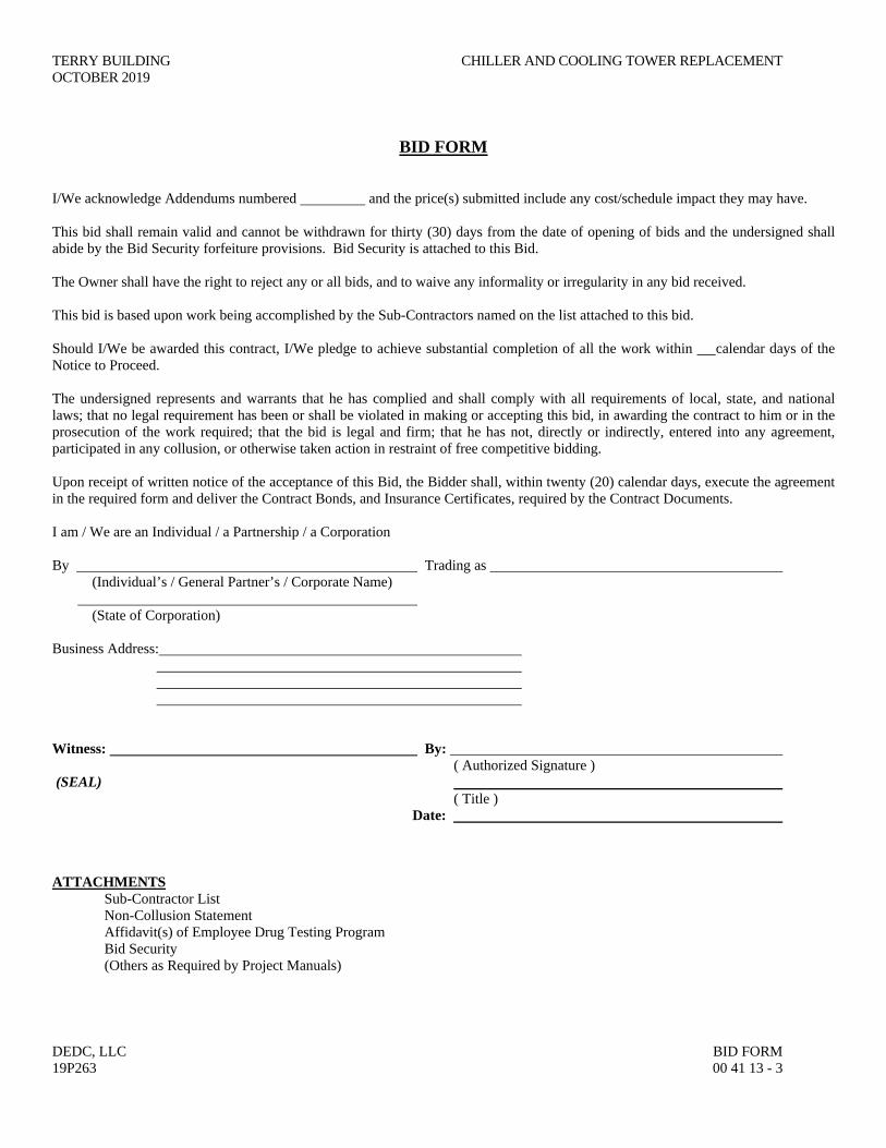
BID FORM
I/We acknowledge Addendums numbered and the price(s) submitted include any cost/schedule impact they may have. This bid shall remain valid and cannot be withdrawn for thirty (30) days from the date of opening of bids and the undersigned shall abide by the Bid Security forfeiture provisions. Bid Security is attached to this Bid. The Owner shall have the right to reject any or all bids, and to waive any informality or irregularity in any bid received. This bid is based upon work being accomplished by the Sub-Contractors named on the list attached to this bid. Should I/We be awarded this contract, I/We pledge to achieve substantial completion of all the work within calendar days of the Notice to Proceed. The undersigned represents and warrants that he has complied and shall comply with all requirements of local, state, and national laws; that no legal requirement has been or shall be violated in making or accepting this bid, in awarding the contract to him or in the prosecution of the work required; that the bid is legal and firm; that he has not, directly or indirectly, entered into any agreement, participated in any collusion, or otherwise taken action in restraint of free competitive bidding. Upon receipt of written notice of the acceptance of this Bid, the Bidder shall, within twenty (20) calendar days, execute the agreement in the required form and deliver the Contract Bonds, and Insurance Certificates, required by the Contract Documents. I am / We are an Individual / a Partnership / a Corporation By Trading as (Individual’s / General Partner’s / Corporate Name) (State of Corporation) Business Address: Witness: By: ( Authorized Signature ) (SEAL) ( Title ) Date: ATTACHMENTS Sub-Contractor List Non-Collusion Statement Affidavit(s) of Employee Drug Testing Program Bid Security (Others as Required by Project Manuals)

CHILLER AND COOLING TOWER REPLACEMENT TERRY BUILDING OCTOBER 2019
BID FORM DEDC, LLC 00 41 13 - 4 19P263
BID FORM
SUBCONTRACTOR LIST
In accordance with Title 29, Chapter 6962 (d)(10)b Delaware Code, the following sub-contractor listing must accompany the bid submittal. The name and address of the sub-contractor must be listed for each category where the bidder intends to use a sub-contractor to perform that category of work. In order to provide full disclosure and acceptance of the bid by the Owner, it is required that bidders list themselves as being the sub-contractor for all categories where he/she is qualified and intends to perform such work. This form must be filled out completely with no additions or deletions. Subcontractor Category Subcontractor Address (City & State) Subcontractors tax payer ID # or Delaware Business license # 1. Mechanical 2. Electrical
TERRY BUILDING CHILLER AND COOLING TOWER REPLACEMENT OCTOBER 2019
DEDC, LLC BID FORM 19P263 00 41 13 - 5
BID FORM
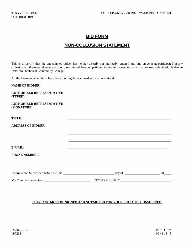
NON-COLLUSION STATEMENT
This is to certify that the undersigned bidder has neither directly nor indirectly, entered into any agreement, participated in any collusion or otherwise taken any action in restraint of free competitive bidding in connection with this proposal submitted this date to Delaware Technical Community College. All the terms and conditions have been thoroughly examined and are understood. NAME OF BIDDER: AUTHORIZED REPRESENTATIVE (TYPED): AUTHORIZED REPRESENTATIVE (SIGNATURE): TITLE: ADDRESS OF BIDDER: E-MAIL: ______________________________________________________________ PHONE NUMBER: Sworn to and Subscribed before me this day of 20 . My Commission expires . NOTARY PUBLIC .
THIS PAGE MUST BE SIGNED AND NOTARIZED FOR YOUR BID TO BE CONSIDERED.

CHILLER AND COOLING TOWER REPLACEMENT TERRY BUILDING OCTOBER 2019
BID FORM DEDC, LLC 00 41 13 - 6 19P263
AFFIDAVIT
OF EMPLOYEE DRUG TESTING PROGRAM
4104 Regulations for the Drug Testing of Contractor and Subcontractor Employees Working on Delaware Technical Community College requires that Contractors and Subcontractors implement a program of mandatory drug testing for Employees. We hereby certify that we have in place or will implement during the entire term of the contract a Mandatory Drug Testing Program for our employees on the jobsite, including subcontractors that complies with this regulation: Contractor/Subcontractor Name: Contractor/Subcontractor Address: Authorized Representative (typed or printed): Authorized Representative (signature): Title: Sworn to and Subscribed before me this day of 20 . My Commission expires . NOTARY PUBLIC .
THIS PAGE MUST BE SIGNED AND NOTARIZED FOR YOUR BID TO BE CONSIDERED.
END OF SECTION
TERRY BUILDING CHILLER AND COOLING TOWER REPLACEMENT OCTOBER 2019
DEDC, LLC BID BOND 19P263 00 43 13 - 1
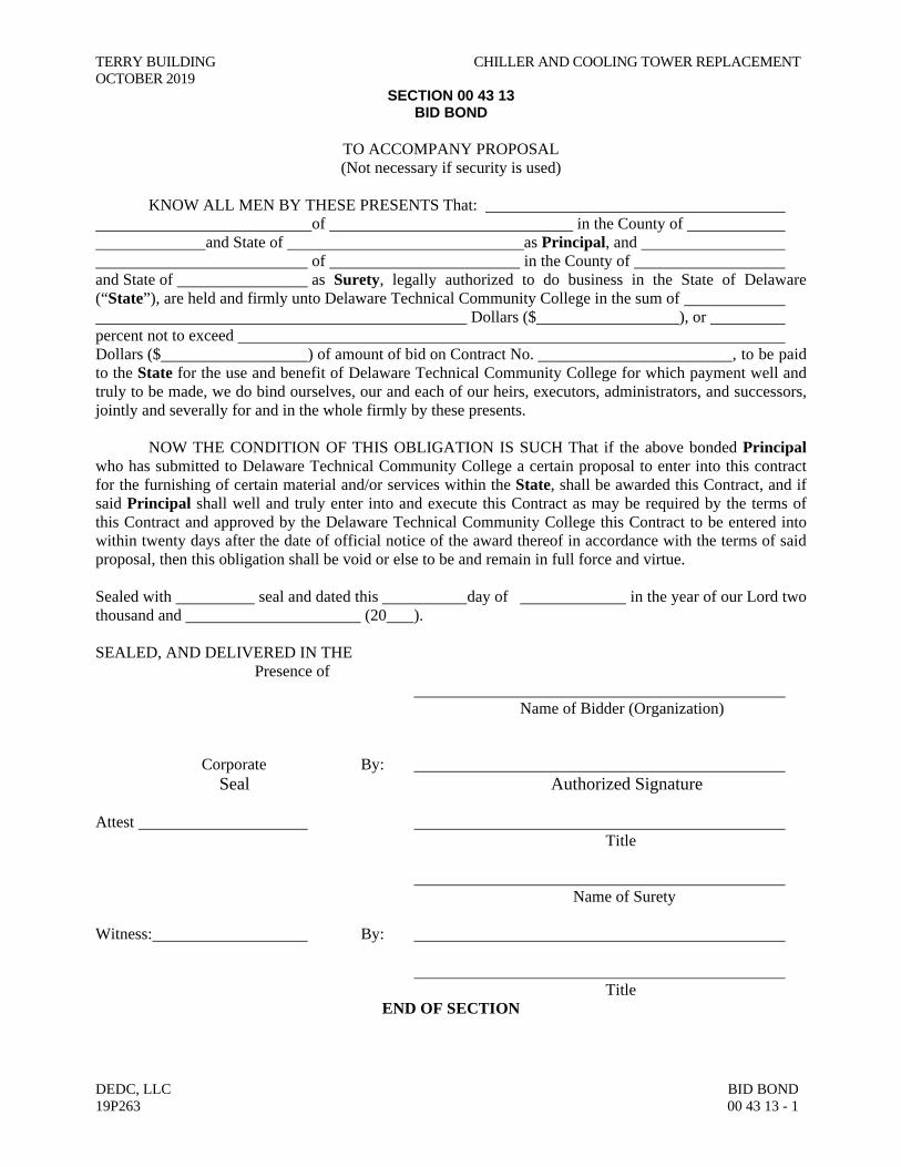
SECTION 00 43 13 BID BOND
TO ACCOMPANY PROPOSAL (Not necessary if security is used)
KNOW ALL MEN BY THESE PRESENTS That:
of in the County of and State of as Principal, and of in the County of and State of as Surety, legally authorized to do business in the State of Delaware (“State”), are held and firmly unto Delaware Technical Community College in the sum of Dollars ($ ), or percent not to exceed Dollars ($ ) of amount of bid on Contract No. , to be paid to the State for the use and benefit of Delaware Technical Community College for which payment well and truly to be made, we do bind ourselves, our and each of our heirs, executors, administrators, and successors, jointly and severally for and in the whole firmly by these presents. NOW THE CONDITION OF THIS OBLIGATION IS SUCH That if the above bonded Principal who has submitted to Delaware Technical Community College a certain proposal to enter into this contract for the furnishing of certain material and/or services within the State, shall be awarded this Contract, and if said Principal shall well and truly enter into and execute this Contract as may be required by the terms of this Contract and approved by the Delaware Technical Community College this Contract to be entered into within twenty days after the date of official notice of the award thereof in accordance with the terms of said proposal, then this obligation shall be void or else to be and remain in full force and virtue. Sealed with seal and dated this day of in the year of our Lord two thousand and (20 ). SEALED, AND DELIVERED IN THE Presence of
Name of Bidder (Organization) Corporate By:
Seal Authorized Signature Attest Title Name of Surety Witness: By: Title
END OF SECTION
CHILLER AND COOLING TOWER REPLACEMENT TERRY BUILDING OCTOBER 2019
BID BOND DEDC, LLC 00 43 13 - 2 19P263
THIS PAGE INTENTIONALLY LEFT BLANK
TERRY BUILDING CHILLER AND COOLING TOWER REPLACEMENT OCTOBER 2019
DEDC, LLC STANDARD FORM OF AGREEMENT BETWEEN OWNER AND CONTRACTOR 19P263 00 52 13 - 1
SECTION 00 52 13 STANDARD FORM OF AGREEMENT BETWEEN OWNER AND CONTRACTOR A101-2017
The contract to be utilized on this project shall be the “Standard Form of Agreement Between Owner and Contractor” AIA Document A101-2017, including AIA Document A101 – 2017 Exhibit A, as well as Supplements to A101-2017 and Exhibit A and the Delaware Technical Community College General Requirements.
END OF SECTION

CHILLER AND COOLING TOWER REPLACEMENT TERRY BUILDING OCTOBER 2019
STANDARD FORM OF AGREEMENT BETWEEN OWNER AND CONTRACTOR DEDC, LLC 00 52 13 – 2 19P263
THIS PAGE INTENTIONALLY LEFT BLANK

AIA®
Document A101TM – 2017 Standard Form of Agreement Between Owner and Contractor where the basis of payment is a Stipulated Sum
AIA Document A101™ – 2017. Copyright © 1915, 1918, 1925, 1937, 1951, 1958, 1961, 1963, 1967, 1974, 1977, 1987, 1991, 1997, 2007 and 2017 byThe American Institute of Architects. All rights reserved. WARNING: This AIA® Document is protected by U.S. Copyright Law and InternationalTreaties. Unauthorized reproduction or distribution of this AIA® Document, or any portion of it, may result in severe civil and criminal penalties,and will be prosecuted to the maximum extent possible under the law. This draft was produced by AIA software at 11:41:14 ET on 11/09/2018 under Order No.5521013211 which expires on 07/19/2019, and is not for resale. User Notes: (1278371941)
1
ADDITIONS AND DELETIONS: The author of this document has added information needed for its completion. The author may also have revised the text of the original AIA standard form. An Additions and Deletions Report that notes added information as well as revisions to the standard form text is available from the author and should be reviewed.
This document has important legal consequences. Consultation with an attorney is encouraged with respect to its completion or modification.
The parties should complete A101™–2017, Exhibit A, Insurance and Bonds, contemporaneously with this Agreement. AIA Document A201™–2017, General Conditions of the Contract for Construction, is adopted in this document by reference. Do not use with other general conditions unless this document is modified.
ELECTRONIC COPYING of any portion of this AIA® Document to another electronic file is prohibited and constitutes a violation of copyright laws as set forth in the footer of this document.
AGREEMENT made as of the « » day of « » in the year « » (In words, indicate day, month and year.) BETWEEN the Owner: (Name, legal status, address and other information) « »« » « » « » « » and the Contractor: (Name, legal status, address and other information) « »« » « » « » « » for the following Project: (Name, location and detailed description) «testing» «» «» The Architect: (Name, legal status, address and other information) « »« » « » « » « » The Owner and Contractor agree as follows.

AIA Document A101™ – 2017. Copyright © 1915, 1918, 1925, 1937, 1951, 1958, 1961, 1963, 1967, 1974, 1977, 1987, 1991, 1997, 2007 and 2017 byThe American Institute of Architects. All rights reserved. WARNING: This AIA® Document is protected by U.S. Copyright Law and InternationalTreaties. Unauthorized reproduction or distribution of this AIA® Document, or any portion of it, may result in severe civil and criminal penalties,and will be prosecuted to the maximum extent possible under the law. This draft was produced by AIA software at 11:41:14 ET on 11/09/2018 under Order No.5521013211 which expires on 07/19/2019, and is not for resale. User Notes: (1278371941)
2
TABLE OF ARTICLES 1 THE CONTRACT DOCUMENTS 2 THE WORK OF THIS CONTRACT 3 DATE OF COMMENCEMENT AND SUBSTANTIAL COMPLETION 4 CONTRACT SUM 5 PAYMENTS 6 DISPUTE RESOLUTION 7 TERMINATION OR SUSPENSION 8 MISCELLANEOUS PROVISIONS 9 ENUMERATION OF CONTRACT DOCUMENTS EXHIBIT A INSURANCE AND BONDS ARTICLE 1 THE CONTRACT DOCUMENTS The Contract Documents consist of this Agreement, Conditions of the Contract (General, Supplementary, and other Conditions), Drawings, Specifications, Addenda issued prior to execution of this Agreement, other documents listed in this Agreement, and Modifications issued after execution of this Agreement, all of which form the Contract, and are as fully a part of the Contract as if attached to this Agreement or repeated herein. The Contract represents the entire and integrated agreement between the parties hereto and supersedes prior negotiations, representations, or agreements, either written or oral. An enumeration of the Contract Documents, other than a Modification, appears in Article 9. ARTICLE 2 THE WORK OF THIS CONTRACT The Contractor shall fully execute the Work described in the Contract Documents, except as specifically indicated in the Contract Documents to be the responsibility of others. ARTICLE 3 DATE OF COMMENCEMENT AND SUBSTANTIAL COMPLETION § 3.1 The date of commencement of the Work shall be: (Check one of the following boxes.)
[ « » ] The date of this Agreement.
[ « » ] A date set forth in a notice to proceed issued by the Owner.
[ « » ] Established as follows: (Insert a date or a means to determine the date of commencement of the Work.)
« »
If a date of commencement of the Work is not selected, then the date of commencement shall be the date of this Agreement. § 3.2 The Contract Time shall be measured from the date of commencement of the Work. § 3.3 Substantial Completion § 3.3.1 Subject to adjustments of the Contract Time as provided in the Contract Documents, the Contractor shall achieve Substantial Completion of the entire Work: (Check one of the following boxes and complete the necessary information.)
[ « » ] Not later than « » ( « » ) calendar days from the date of commencement of the Work.
AIA Document A101™ – 2017. Copyright © 1915, 1918, 1925, 1937, 1951, 1958, 1961, 1963, 1967, 1974, 1977, 1987, 1991, 1997, 2007 and 2017 byThe American Institute of Architects. All rights reserved. WARNING: This AIA® Document is protected by U.S. Copyright Law and InternationalTreaties. Unauthorized reproduction or distribution of this AIA® Document, or any portion of it, may result in severe civil and criminal penalties,and will be prosecuted to the maximum extent possible under the law. This draft was produced by AIA software at 11:41:14 ET on 11/09/2018 under Order No.5521013211 which expires on 07/19/2019, and is not for resale. User Notes: (1278371941)
3
[ « » ] By the following date: « »
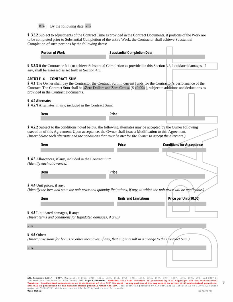
§ 3.3.2 Subject to adjustments of the Contract Time as provided in the Contract Documents, if portions of the Work are to be completed prior to Substantial Completion of the entire Work, the Contractor shall achieve Substantial Completion of such portions by the following dates:
Portion of Work Substantial Completion Date
§ 3.3.3 If the Contractor fails to achieve Substantial Completion as provided in this Section 3.3, liquidated damages, if any, shall be assessed as set forth in Section 4.5. ARTICLE 4 CONTRACT SUM § 4.1 The Owner shall pay the Contractor the Contract Sum in current funds for the Contractor’s performance of the Contract. The Contract Sum shall be «Zero Dollars and Zero Cents» ($ «0.00» ), subject to additions and deductions as provided in the Contract Documents. § 4.2 Alternates § 4.2.1 Alternates, if any, included in the Contract Sum:
Item Price
§ 4.2.2 Subject to the conditions noted below, the following alternates may be accepted by the Owner following execution of this Agreement. Upon acceptance, the Owner shall issue a Modification to this Agreement. (Insert below each alternate and the conditions that must be met for the Owner to accept the alternate.)
Item Price Conditions for Acceptance
§ 4.3 Allowances, if any, included in the Contract Sum: (Identify each allowance.)
Item Price
§ 4.4 Unit prices, if any: (Identify the item and state the unit price and quantity limitations, if any, to which the unit price will be applicable.)
Item Units and Limitations Price per Unit ($0.00)
§ 4.5 Liquidated damages, if any: (Insert terms and conditions for liquidated damages, if any.) « » § 4.6 Other: (Insert provisions for bonus or other incentives, if any, that might result in a change to the Contract Sum.) « »

AIA Document A101™ – 2017. Copyright © 1915, 1918, 1925, 1937, 1951, 1958, 1961, 1963, 1967, 1974, 1977, 1987, 1991, 1997, 2007 and 2017 byThe American Institute of Architects. All rights reserved. WARNING: This AIA® Document is protected by U.S. Copyright Law and InternationalTreaties. Unauthorized reproduction or distribution of this AIA® Document, or any portion of it, may result in severe civil and criminal penalties,and will be prosecuted to the maximum extent possible under the law. This draft was produced by AIA software at 11:41:14 ET on 11/09/2018 under Order No.5521013211 which expires on 07/19/2019, and is not for resale. User Notes: (1278371941)
4
ARTICLE 5 PAYMENTS § 5.1 Progress Payments § 5.1.1 Based upon Applications for Payment submitted to the Architect by the Contractor and Certificates for Payment issued by the Architect, the Owner shall make progress payments on account of the Contract Sum to the Contractor as provided below and elsewhere in the Contract Documents. § 5.1.2 The period covered by each Application for Payment shall be one calendar month ending on the last day of the month, or as follows: « » § 5.1.3 Provided that an Application for Payment is received by the Architect not later than the « » day of a month, the Owner shall make payment of the amount certified to the Contractor not later than the « » day of the « » month. If an Application for Payment is received by the Architect after the application date fixed above, payment of the amount certified shall be made by the Owner not later than « » ( « » ) days after the Architect receives the Application for Payment. (Federal, state or local laws may require payment within a certain period of time.) § 5.1.4 Each Application for Payment shall be based on the most recent schedule of values submitted by the Contractor in accordance with the Contract Documents. The schedule of values shall allocate the entire Contract Sum among the various portions of the Work. The schedule of values shall be prepared in such form, and supported by such data to substantiate its accuracy, as the Architect may require. This schedule of values shall be used as a basis for reviewing the Contractor’s Applications for Payment. § 5.1.5 Applications for Payment shall show the percentage of completion of each portion of the Work as of the end of the period covered by the Application for Payment. § 5.1.6 In accordance with AIA Document A201™–2017, General Conditions of the Contract for Construction, and subject to other provisions of the Contract Documents, the amount of each progress payment shall be computed as follows: § 5.1.6.1 The amount of each progress payment shall first include:
.1 That portion of the Contract Sum properly allocable to completed Work;
.2 That portion of the Contract Sum properly allocable to materials and equipment delivered and suitably stored at the site for subsequent incorporation in the completed construction, or, if approved in advance by the Owner, suitably stored off the site at a location agreed upon in writing; and
.3 That portion of Construction Change Directives that the Architect determines, in the Architect’s professional judgment, to be reasonably justified.
§ 5.1.6.2 The amount of each progress payment shall then be reduced by:
.1 The aggregate of any amounts previously paid by the Owner;
.2 The amount, if any, for Work that remains uncorrected and for which the Architect has previously withheld a Certificate for Payment as provided in Article 9 of AIA Document A201–2017;
.3 Any amount for which the Contractor does not intend to pay a Subcontractor or material supplier, unless the Work has been performed by others the Contractor intends to pay;
.4 For Work performed or defects discovered since the last payment application, any amount for which the Architect may withhold payment, or nullify a Certificate of Payment in whole or in part, as provided in Article 9 of AIA Document A201–2017; and
.5 Retainage withheld pursuant to Section 5.1.7. § 5.1.7 Retainage § 5.1.7.1 For each progress payment made prior to Substantial Completion of the Work, the Owner may withhold the following amount, as retainage, from the payment otherwise due: (Insert a percentage or amount to be withheld as retainage from each Application for Payment. The amount of retainage may be limited by governing law.) « »
AIA Document A101™ – 2017. Copyright © 1915, 1918, 1925, 1937, 1951, 1958, 1961, 1963, 1967, 1974, 1977, 1987, 1991, 1997, 2007 and 2017 byThe American Institute of Architects. All rights reserved. WARNING: This AIA® Document is protected by U.S. Copyright Law and InternationalTreaties. Unauthorized reproduction or distribution of this AIA® Document, or any portion of it, may result in severe civil and criminal penalties,and will be prosecuted to the maximum extent possible under the law. This draft was produced by AIA software at 11:41:14 ET on 11/09/2018 under Order No.5521013211 which expires on 07/19/2019, and is not for resale. User Notes: (1278371941)
5
§ 5.1.7.1.1 The following items are not subject to retainage: (Insert any items not subject to the withholding of retainage, such as general conditions, insurance, etc.) « » § 5.1.7.2 Reduction or limitation of retainage, if any, shall be as follows: (If the retainage established in Section 5.1.7.1 is to be modified prior to Substantial Completion of the entire Work, including modifications for Substantial Completion of portions of the Work as provided in Section 3.3.2, insert provisions for such modifications.) « » § 5.1.7.3 Except as set forth in this Section 5.1.7.3, upon Substantial Completion of the Work, the Contractor may submit an Application for Payment that includes the retainage withheld from prior Applications for Payment pursuant to this Section 5.1.7. The Application for Payment submitted at Substantial Completion shall not include retainage as follows: (Insert any other conditions for release of retainage upon Substantial Completion.) « » § 5.1.8 If final completion of the Work is materially delayed through no fault of the Contractor, the Owner shall pay the Contractor any additional amounts in accordance with Article 9 of AIA Document A201–2017. § 5.1.9 Except with the Owner’s prior approval, the Contractor shall not make advance payments to suppliers for materials or equipment which have not been delivered and stored at the site. § 5.2 Final Payment § 5.2.1 Final payment, constituting the entire unpaid balance of the Contract Sum, shall be made by the Owner to the Contractor when
.1 the Contractor has fully performed the Contract except for the Contractor’s responsibility to correct Work as provided in Article 12 of AIA Document A201–2017, and to satisfy other requirements, if any, which extend beyond final payment; and
.2 a final Certificate for Payment has been issued by the Architect. § 5.2.2 The Owner’s final payment to the Contractor shall be made no later than 30 days after the issuance of the Architect’s final Certificate for Payment, or as follows: « » § 5.3 Interest Payments due and unpaid under the Contract shall bear interest from the date payment is due at the rate stated below, or in the absence thereof, at the legal rate prevailing from time to time at the place where the Project is located. (Insert rate of interest agreed upon, if any.) « » % « » ARTICLE 6 DISPUTE RESOLUTION § 6.1 Initial Decision Maker The Architect will serve as the Initial Decision Maker pursuant to Article 15 of AIA Document A201–2017, unless the parties appoint below another individual, not a party to this Agreement, to serve as the Initial Decision Maker. (If the parties mutually agree, insert the name, address and other contact information of the Initial Decision Maker, if other than the Architect.) « » « » « » « »
AIA Document A101™ – 2017. Copyright © 1915, 1918, 1925, 1937, 1951, 1958, 1961, 1963, 1967, 1974, 1977, 1987, 1991, 1997, 2007 and 2017 byThe American Institute of Architects. All rights reserved. WARNING: This AIA® Document is protected by U.S. Copyright Law and InternationalTreaties. Unauthorized reproduction or distribution of this AIA® Document, or any portion of it, may result in severe civil and criminal penalties,and will be prosecuted to the maximum extent possible under the law. This draft was produced by AIA software at 11:41:14 ET on 11/09/2018 under Order No.5521013211 which expires on 07/19/2019, and is not for resale. User Notes: (1278371941)
6
§ 6.2 Binding Dispute Resolution For any Claim subject to, but not resolved by, mediation pursuant to Article 15 of AIA Document A201–2017, the method of binding dispute resolution shall be as follows: (Check the appropriate box.)
[ « » ] Arbitration pursuant to Section 15.4 of AIA Document A201–2017
[ « » ] Litigation in a court of competent jurisdiction
[ « » ] Other (Specify)
« » If the Owner and Contractor do not select a method of binding dispute resolution, or do not subsequently agree in writing to a binding dispute resolution method other than litigation, Claims will be resolved by litigation in a court of competent jurisdiction. ARTICLE 7 TERMINATION OR SUSPENSION § 7.1 The Contract may be terminated by the Owner or the Contractor as provided in Article 14 of AIA Document A201–2017. § 7.1.1 If the Contract is terminated for the Owner’s convenience in accordance with Article 14 of AIA Document A201–2017, then the Owner shall pay the Contractor a termination fee as follows: (Insert the amount of, or method for determining, the fee, if any, payable to the Contractor following a termination for the Owner’s convenience.) « » § 7.2 The Work may be suspended by the Owner as provided in Article 14 of AIA Document A201–2017. ARTICLE 8 MISCELLANEOUS PROVISIONS § 8.1 Where reference is made in this Agreement to a provision of AIA Document A201–2017 or another Contract Document, the reference refers to that provision as amended or supplemented by other provisions of the Contract Documents. § 8.2 The Owner’s representative: (Name, address, email address, and other information) « » « » « » « » « » « » § 8.3 The Contractor’s representative: (Name, address, email address, and other information) « » « » « » « » « » « » § 8.4 Neither the Owner’s nor the Contractor’s representative shall be changed without ten days’ prior notice to the other party.

AIA Document A101™ – 2017. Copyright © 1915, 1918, 1925, 1937, 1951, 1958, 1961, 1963, 1967, 1974, 1977, 1987, 1991, 1997, 2007 and 2017 byThe American Institute of Architects. All rights reserved. WARNING: This AIA® Document is protected by U.S. Copyright Law and InternationalTreaties. Unauthorized reproduction or distribution of this AIA® Document, or any portion of it, may result in severe civil and criminal penalties,and will be prosecuted to the maximum extent possible under the law. This draft was produced by AIA software at 11:41:14 ET on 11/09/2018 under Order No.5521013211 which expires on 07/19/2019, and is not for resale. User Notes: (1278371941)
7
§ 8.5 Insurance and Bonds § 8.5.1 The Owner and the Contractor shall purchase and maintain insurance as set forth in AIA Document A101™–2017, Standard Form of Agreement Between Owner and Contractor where the basis of payment is a Stipulated Sum, Exhibit A, Insurance and Bonds, and elsewhere in the Contract Documents. § 8.5.2 The Contractor shall provide bonds as set forth in AIA Document A101™–2017 Exhibit A, and elsewhere in the Contract Documents. § 8.6 Notice in electronic format, pursuant to Article 1 of AIA Document A201–2017, may be given in accordance with AIA Document E203™–2013, Building Information Modeling and Digital Data Exhibit, if completed, or as otherwise set forth below: (If other than in accordance with AIA Document E203–2013, insert requirements for delivering notice in electronic format such as name, title, and email address of the recipient and whether and how the system will be required to generate a read receipt for the transmission.) « » § 8.7 Other provisions: « » ARTICLE 9 ENUMERATION OF CONTRACT DOCUMENTS § 9.1 This Agreement is comprised of the following documents:
.1 AIA Document A101™–2017, Standard Form of Agreement Between Owner and Contractor
.2 AIA Document A101™–2017, Exhibit A, Insurance and Bonds
.3 AIA Document A201™–2017, General Conditions of the Contract for Construction
.4 AIA Document E203™–2013, Building Information Modeling and Digital Data Exhibit, dated as indicated below: (Insert the date of the E203-2013 incorporated into this Agreement.)
« »
.5 Drawings
Number Title Date
.6 Specifications
Section Title Date Pages
.7 Addenda, if any:
Number Date Pages
Portions of Addenda relating to bidding or proposal requirements are not part of the Contract Documents unless the bidding or proposal requirements are also enumerated in this Article 9.
.8 Other Exhibits:
(Check all boxes that apply and include appropriate information identifying the exhibit where required.)
[ « » ] AIA Document E204™–2017, Sustainable Projects Exhibit, dated as indicated below:
(Insert the date of the E204-2017 incorporated into this Agreement.)
« »

AIA Document A101™ – 2017. Copyright © 1915, 1918, 1925, 1937, 1951, 1958, 1961, 1963, 1967, 1974, 1977, 1987, 1991, 1997, 2007 and 2017 byThe American Institute of Architects. All rights reserved. WARNING: This AIA® Document is protected by U.S. Copyright Law and InternationalTreaties. Unauthorized reproduction or distribution of this AIA® Document, or any portion of it, may result in severe civil and criminal penalties,and will be prosecuted to the maximum extent possible under the law. This draft was produced by AIA software at 11:41:14 ET on 11/09/2018 under Order No.5521013211 which expires on 07/19/2019, and is not for resale. User Notes: (1278371941)
8
[ « » ] The Sustainability Plan:
Title Date Pages
[ « » ] Supplementary and other Conditions of the Contract:
Document Title Date Pages
.9 Other documents, if any, listed below:
(List here any additional documents that are intended to form part of the Contract Documents. AIA Document A201™–2017 provides that the advertisement or invitation to bid, Instructions to Bidders, sample forms, the Contractor’s bid or proposal, portions of Addenda relating to bidding or proposal requirements, and other information furnished by the Owner in anticipation of receiving bids or proposals, are not part of the Contract Documents unless enumerated in this Agreement. Any such documents should be listed here only if intended to be part of the Contract Documents.)
« »
This Agreement entered into as of the day and year first written above.
OWNER (Signature) CONTRACTOR (Signature)
« »« » « »« » (Printed name and title) (Printed name and title)

AIA®
Document A101TM – 2017 Exhibit A Insurance and Bonds
AIA Document A101™ – 2017 Exhibit A. Copyright © 2017 by The American Institute of Architects. All rights reserved. WARNING: This AIA® Document is protected by U.S. Copyright Law and International Treaties. Unauthorized reproduction or distribution of this AIA® Document, or any portion of it, may result in severe civil and criminal penalties, and will be prosecuted to the maximum extent possible under the law. This draft was produced by AIA software at 15:53:16 ET on 11/08/2018 under Order No.5521013211 which expires on 07/19/2019, and is not for resale. User Notes: (1933659252)
1
ADDITIONS AND DELETIONS: The author of this document has added information needed for its completion. The author may also have revised the text of the original AIA standard form. An Additions and Deletions Report that notes added information as well as revisions to the standard form text is available from the author and should be reviewed.
This document has important legal consequences. Consultation with an attorney is encouraged with respect to its completion or modification.
This document is intended to be used in conjunction with AIA Document A201™–2017, General Conditions of the Contract for Construction. Article 11 of A201™–2017 contains additional insurance provisions.
ELECTRONIC COPYING of any portion of this AIA® Document to another electronic file is prohibited and constitutes a violation of copyright laws as set forth in the footer of this document.
This Insurance and Bonds Exhibit is part of the Agreement, between the Owner and the Contractor, dated the « » day of « » in the year « » (In words, indicate day, month and year.) for the following PROJECT: (Name and location or address) «» «» THE OWNER: (Name, legal status and address) « »« » « » THE CONTRACTOR: (Name, legal status and address) « »« » « » TABLE OF ARTICLES A.1 GENERAL A.2 OWNER’S INSURANCE A.3 CONTRACTOR’S INSURANCE AND BONDS A.4 SPECIAL TERMS AND CONDITIONS ARTICLE A.1 GENERAL The Owner and Contractor shall purchase and maintain insurance, and provide bonds, as set forth in this Exhibit. As used in this Exhibit, the term General Conditions refers to AIA Document A201™–2017, General Conditions of the Contract for Construction. ARTICLE A.2 OWNER’S INSURANCE § A.2.1 General Prior to commencement of the Work, the Owner shall secure the insurance, and provide evidence of the coverage, required under this Article A.2 and, upon the Contractor’s request, provide a copy of the property insurance policy or policies required by Section A.2.3. The copy of the policy or policies provided shall contain all applicable conditions, definitions, exclusions, and endorsements. § A.2.2 Liability Insurance The Owner shall be responsible for purchasing and maintaining the Owner’s usual general liability insurance. § A.2.3 Required Property Insurance

AIA Document A101™ – 2017 Exhibit A. Copyright © 2017 by The American Institute of Architects. All rights reserved. WARNING: This AIA® Document is protected by U.S. Copyright Law and International Treaties. Unauthorized reproduction or distribution of this AIA® Document, or any portion of it, may result in severe civil and criminal penalties, and will be prosecuted to the maximum extent possible under the law. This draft was produced by AIA software at 15:53:16 ET on 11/08/2018 under Order No.5521013211 which expires on 07/19/2019, and is not for resale. User Notes: (1933659252)
2
§ A.2.3.1 Unless this obligation is placed on the Contractor pursuant to Section A.3.3.2.1, the Owner shall purchase and maintain, from an insurance company or insurance companies lawfully authorized to issue insurance in the jurisdiction where the Project is located, property insurance written on a builder's risk “all-risks” completed value or equivalent policy form and sufficient to cover the total value of the entire Project on a replacement cost basis. The Owner’s property insurance coverage shall be no less than the amount of the initial Contract Sum, plus the value of subsequent Modifications and labor performed and materials or equipment supplied by others. The property insurance shall be maintained until Substantial Completion and thereafter as provided in Section A.2.3.1.3, unless otherwise provided in the Contract Documents or otherwise agreed in writing by the parties to this Agreement. This insurance shall include the interests of the Owner, Contractor, Subcontractors, and Sub-subcontractors in the Project as insureds. This insurance shall include the interests of mortgagees as loss payees. § A.2.3.1.1 Causes of Loss. The insurance required by this Section A.2.3.1 shall provide coverage for direct physical loss or damage, and shall not exclude the risks of fire, explosion, theft, vandalism, malicious mischief, collapse, earthquake, flood, or windstorm. The insurance shall also provide coverage for ensuing loss or resulting damage from error, omission, or deficiency in construction methods, design, specifications, workmanship, or materials. Sub-limits, if any, are as follows: (Indicate below the cause of loss and any applicable sub-limit.)
Causes of Loss Sub-Limit
§ A.2.3.1.2 Specific Required Coverages. The insurance required by this Section A.2.3.1 shall provide coverage for loss or damage to falsework and other temporary structures, and to building systems from testing and startup. The insurance shall also cover debris removal, including demolition occasioned by enforcement of any applicable legal requirements, and reasonable compensation for the Architect’s and Contractor’s services and expenses required as a result of such insured loss, including claim preparation expenses. Sub-limits, if any, are as follows: (Indicate below type of coverage and any applicable sub-limit for specific required coverages.)
Coverage Sub-Limit
§ A.2.3.1.3 Unless the parties agree otherwise, upon Substantial Completion, the Owner shall continue the insurance required by Section A.2.3.1 or, if necessary, replace the insurance policy required under Section A.2.3.1 with property insurance written for the total value of the Project that shall remain in effect until expiration of the period for correction of the Work set forth in Section 12.2.2 of the General Conditions. § A.2.3.1.4 Deductibles and Self-Insured Retentions. If the insurance required by this Section A.2.3 is subject to deductibles or self-insured retentions, the Owner shall be responsible for all loss not covered because of such deductibles or retentions. § A.2.3.2 Occupancy or Use Prior to Substantial Completion. The Owner’s occupancy or use of any completed or partially completed portion of the Work prior to Substantial Completion shall not commence until the insurance company or companies providing the insurance under Section A.2.3.1 have consented in writing to the continuance of coverage. The Owner and the Contractor shall take no action with respect to partial occupancy or use that would cause cancellation, lapse, or reduction of insurance, unless they agree otherwise in writing. § A.2.3.3 Insurance for Existing Structures If the Work involves remodeling an existing structure or constructing an addition to an existing structure, the Owner shall purchase and maintain, until the expiration of the period for correction of Work as set forth in Section 12.2.2 of the General Conditions, “all-risks” property insurance, on a replacement cost basis, protecting the existing structure against direct physical loss or damage from the causes of loss identified in Section A.2.3.1, notwithstanding the undertaking of the Work. The Owner shall be responsible for all co-insurance penalties. § A.2.4 Optional Extended Property Insurance. The Owner shall purchase and maintain the insurance selected and described below.

AIA Document A101™ – 2017 Exhibit A. Copyright © 2017 by The American Institute of Architects. All rights reserved. WARNING: This AIA® Document is protected by U.S. Copyright Law and International Treaties. Unauthorized reproduction or distribution of this AIA® Document, or any portion of it, may result in severe civil and criminal penalties, and will be prosecuted to the maximum extent possible under the law. This draft was produced by AIA software at 15:53:16 ET on 11/08/2018 under Order No.5521013211 which expires on 07/19/2019, and is not for resale. User Notes: (1933659252)
3
(Select the types of insurance the Owner is required to purchase and maintain by placing an X in the box(es) next to the description(s) of selected insurance. For each type of insurance selected, indicate applicable limits of coverage or other conditions in the fill point below the selected item.)
[ « » ] § A.2.4.1 Loss of Use, Business Interruption, and Delay in Completion Insurance, to reimburse the Owner for loss of use of the Owner’s property, or the inability to conduct normal operations due to a covered cause of loss.
« »
[ « » ] § A.2.4.2 Ordinance or Law Insurance, for the reasonable and necessary costs to satisfy the minimum
requirements of the enforcement of any law or ordinance regulating the demolition, construction, repair, replacement or use of the Project.
« »
[ « » ] § A.2.4.3 Expediting Cost Insurance, for the reasonable and necessary costs for the temporary repair of
damage to insured property, and to expedite the permanent repair or replacement of the damaged property.
« »
[ « » ] § A.2.4.4 Extra Expense Insurance, to provide reimbursement of the reasonable and necessary excess
costs incurred during the period of restoration or repair of the damaged property that are over and above the total costs that would normally have been incurred during the same period of time had no loss or damage occurred.
« »
[ « » ] § A.2.4.5 Civil Authority Insurance, for losses or costs arising from an order of a civil authority
prohibiting access to the Project, provided such order is the direct result of physical damage covered under the required property insurance.
« »
[ « » ] § A.2.4.6 Ingress/Egress Insurance, for loss due to the necessary interruption of the insured’s business
due to physical prevention of ingress to, or egress from, the Project as a direct result of physical damage.
« »
[ « » ] § A.2.4.7 Soft Costs Insurance, to reimburse the Owner for costs due to the delay of completion of the
Work, arising out of physical loss or damage covered by the required property insurance: including construction loan fees; leasing and marketing expenses; additional fees, including those of architects, engineers, consultants, attorneys and accountants, needed for the completion of the construction, repairs, or reconstruction; and carrying costs such as property taxes, building permits, additional interest on loans, realty taxes, and insurance premiums over and above normal expenses.
« »
§ A.2.5 Other Optional Insurance. The Owner shall purchase and maintain the insurance selected below. (Select the types of insurance the Owner is required to purchase and maintain by placing an X in the box(es) next to the description(s) of selected insurance.)
AIA Document A101™ – 2017 Exhibit A. Copyright © 2017 by The American Institute of Architects. All rights reserved. WARNING: This AIA® Document is protected by U.S. Copyright Law and International Treaties. Unauthorized reproduction or distribution of this AIA® Document, or any portion of it, may result in severe civil and criminal penalties, and will be prosecuted to the maximum extent possible under the law. This draft was produced by AIA software at 15:53:16 ET on 11/08/2018 under Order No.5521013211 which expires on 07/19/2019, and is not for resale. User Notes: (1933659252)
4
[ « » ] § A.2.5.1 Cyber Security Insurance for loss to the Owner due to data security and privacy breach, including costs of investigating a potential or actual breach of confidential or private information. (Indicate applicable limits of coverage or other conditions in the fill point below.)
« »
[ « » ] § A.2.5.2 Other Insurance
(List below any other insurance coverage to be provided by the Owner and any applicable limits.)
Coverage Limits
ARTICLE A.3 CONTRACTOR’S INSURANCE AND BONDS § A.3.1 General § A.3.1.1 Certificates of Insurance. The Contractor shall provide certificates of insurance acceptable to the Owner evidencing compliance with the requirements in this Article A.3 at the following times: (1) prior to commencement of the Work; (2) upon renewal or replacement of each required policy of insurance; and (3) upon the Owner’s written request. An additional certificate evidencing continuation of commercial liability coverage, including coverage for completed operations, shall be submitted with the final Application for Payment and thereafter upon renewal or replacement of such coverage until the expiration of the periods required by Section A.3.2.1 and Section A.3.3.1. The certificates will show the Owner as an additional insured on the Contractor’s Commercial General Liability and excess or umbrella liability policy or policies. § A.3.1.2 Deductibles and Self-Insured Retentions. The Contractor shall disclose to the Owner any deductible or self- insured retentions applicable to any insurance required to be provided by the Contractor. § A.3.1.3 Additional Insured Obligations. To the fullest extent permitted by law, the Contractor shall cause the commercial general liability coverage to include (1) the Owner, the Architect, and the Architect’s consultants as additional insureds for claims caused in whole or in part by the Contractor’s negligent acts or omissions during the Contractor’s operations; and (2) the Owner as an additional insured for claims caused in whole or in part by the Contractor’s negligent acts or omissions for which loss occurs during completed operations. The additional insured coverage shall be primary and non-contributory to any of the Owner’s general liability insurance policies and shall apply to both ongoing and completed operations. To the extent commercially available, the additional insured coverage shall be no less than that provided by Insurance Services Office, Inc. (ISO) forms CG 20 10 07 04, CG 20 37 07 04, and, with respect to the Architect and the Architect’s consultants, CG 20 32 07 04. § A.3.2 Contractor’s Required Insurance Coverage § A.3.2.1 The Contractor shall purchase and maintain the following types and limits of insurance from an insurance company or insurance companies lawfully authorized to issue insurance in the jurisdiction where the Project is located. The Contractor shall maintain the required insurance until the expiration of the period for correction of Work as set forth in Section 12.2.2 of the General Conditions, unless a different duration is stated below: (If the Contractor is required to maintain insurance for a duration other than the expiration of the period for correction of Work, state the duration.) « » § A.3.2.2 Commercial General Liability § A.3.2.2.1 Commercial General Liability insurance for the Project written on an occurrence form with policy limits of not less than « » ($ « » ) each occurrence, « » ($ « » ) general aggregate, and « » ($ « » ) aggregate for products-completed operations hazard, providing coverage for claims including
.1 damages because of bodily injury, sickness or disease, including occupational sickness or disease, and death of any person;
.2 personal injury and advertising injury;
.3 damages because of physical damage to or destruction of tangible property, including the loss of use of such property;
.4 bodily injury or property damage arising out of completed operations; and

AIA Document A101™ – 2017 Exhibit A. Copyright © 2017 by The American Institute of Architects. All rights reserved. WARNING: This AIA® Document is protected by U.S. Copyright Law and International Treaties. Unauthorized reproduction or distribution of this AIA® Document, or any portion of it, may result in severe civil and criminal penalties, and will be prosecuted to the maximum extent possible under the law. This draft was produced by AIA software at 15:53:16 ET on 11/08/2018 under Order No.5521013211 which expires on 07/19/2019, and is not for resale. User Notes: (1933659252)
5
.5 the Contractor’s indemnity obligations under Section 3.18 of the General Conditions. § A.3.2.2.2 The Contractor’s Commercial General Liability policy under this Section A.3.2.2 shall not contain an exclusion or restriction of coverage for the following:
.1 Claims by one insured against another insured, if the exclusion or restriction is based solely on the fact that the claimant is an insured, and there would otherwise be coverage for the claim.
.2 Claims for property damage to the Contractor’s Work arising out of the products-completed operations hazard where the damaged Work or the Work out of which the damage arises was performed by a Subcontractor.
.3 Claims for bodily injury other than to employees of the insured.
.4 Claims for indemnity under Section 3.18 of the General Conditions arising out of injury to employees of the insured.
.5 Claims or loss excluded under a prior work endorsement or other similar exclusionary language.
.6 Claims or loss due to physical damage under a prior injury endorsement or similar exclusionary language.
.7 Claims related to residential, multi-family, or other habitational projects, if the Work is to be performed on such a project.
.8 Claims related to roofing, if the Work involves roofing.
.9 Claims related to exterior insulation finish systems (EIFS), synthetic stucco or similar exterior coatings or surfaces, if the Work involves such coatings or surfaces.
.10 Claims related to earth subsidence or movement, where the Work involves such hazards.
.11 Claims related to explosion, collapse and underground hazards, where the Work involves such hazards. § A.3.2.3 Automobile Liability covering vehicles owned, and non-owned vehicles used, by the Contractor, with policy limits of not less than « » ($ « » ) per accident, for bodily injury, death of any person, and property damage arising out of the ownership, maintenance and use of those motor vehicles along with any other statutorily required automobile coverage. § A.3.2.4 The Contractor may achieve the required limits and coverage for Commercial General Liability and Automobile Liability through a combination of primary and excess or umbrella liability insurance, provided such primary and excess or umbrella insurance policies result in the same or greater coverage as the coverages required under Section A.3.2.2 and A.3.2.3, and in no event shall any excess or umbrella liability insurance provide narrower coverage than the primary policy. The excess policy shall not require the exhaustion of the underlying limits only through the actual payment by the underlying insurers. § A.3.2.5 Workers’ Compensation at statutory limits. § A.3.2.6 Employers’ Liability with policy limits not less than « » ($ « » ) each accident, « » ($ « » ) each employee, and « » ($ « » ) policy limit. § A.3.2.7 Jones Act, and the Longshore & Harbor Workers’ Compensation Act, as required, if the Work involves hazards arising from work on or near navigable waterways, including vessels and docks § A.3.2.8 If the Contractor is required to furnish professional services as part of the Work, the Contractor shall procure Professional Liability insurance covering performance of the professional services, with policy limits of not less than « » ($ « » ) per claim and « » ($ « » ) in the aggregate. § A.3.2.9 If the Work involves the transport, dissemination, use, or release of pollutants, the Contractor shall procure Pollution Liability insurance, with policy limits of not less than « » ($ « » ) per claim and « » ($ « » ) in the aggregate. § A.3.2.10 Coverage under Sections A.3.2.8 and A.3.2.9 may be procured through a Combined Professional Liability and Pollution Liability insurance policy, with combined policy limits of not less than « » ($ « » ) per claim and « » ($ « » ) in the aggregate. § A.3.2.11 Insurance for maritime liability risks associated with the operation of a vessel, if the Work requires such activities, with policy limits of not less than « » ($ « » ) per claim and « » ($ « » ) in the aggregate.
AIA Document A101™ – 2017 Exhibit A. Copyright © 2017 by The American Institute of Architects. All rights reserved. WARNING: This AIA® Document is protected by U.S. Copyright Law and International Treaties. Unauthorized reproduction or distribution of this AIA® Document, or any portion of it, may result in severe civil and criminal penalties, and will be prosecuted to the maximum extent possible under the law. This draft was produced by AIA software at 15:53:16 ET on 11/08/2018 under Order No.5521013211 which expires on 07/19/2019, and is not for resale. User Notes: (1933659252)
6
§ A.3.2.12 Insurance for the use or operation of manned or unmanned aircraft, if the Work requires such activities, with policy limits of not less than « » ($ « » ) per claim and « » ($ « » ) in the aggregate. § A.3.3 Contractor’s Other Insurance Coverage § A.3.3.1 Insurance selected and described in this Section A.3.3 shall be purchased from an insurance company or insurance companies lawfully authorized to issue insurance in the jurisdiction where the Project is located. The Contractor shall maintain the required insurance until the expiration of the period for correction of Work as set forth in Section 12.2.2 of the General Conditions, unless a different duration is stated below: (If the Contractor is required to maintain any of the types of insurance selected below for a duration other than the expiration of the period for correction of Work, state the duration.) « » § A.3.3.2 The Contractor shall purchase and maintain the following types and limits of insurance in accordance with Section A.3.3.1. (Select the types of insurance the Contractor is required to purchase and maintain by placing an X in the box(es) next to the description(s) of selected insurance. Where policy limits are provided, include the policy limit in the appropriate fill point.)
[ « » ] § A.3.3.2.1 Property insurance of the same type and scope satisfying the requirements identified in Section A.2.3, which, if selected in this section A.3.3.2.1, relieves the Owner of the responsibility to purchase and maintain such insurance except insurance required by Section A.2.3.1.3 and Section A.2.3.3. The Contractor shall comply with all obligations of the Owner under Section A.2.3 except to the extent provided below. The Contractor shall disclose to the Owner the amount of any deductible, and the Owner shall be responsible for losses within the deductible. Upon request, the Contractor shall provide the Owner with a copy of the property insurance policy or policies required. The Owner shall adjust and settle the loss with the insurer and be the trustee of the proceeds of the property insurance in accordance with Article 11 of the General Conditions unless otherwise set forth below: (Where the Contractor’s obligation to provide property insurance differs from the Owner’s obligations as described under Section A.2.3, indicate such differences in the space below. Additionally, if a party other than the Owner will be responsible for adjusting and settling a loss with the insurer and acting as the trustee of the proceeds of property insurance in accordance with Article 11 of the General Conditions, indicate the responsible party below.)
« »
[ « » ] § A.3.3.2.2 Railroad Protective Liability Insurance, with policy limits of not less than « » ($ « » ) per
claim and « » ($ « » ) in the aggregate, for Work within fifty (50) feet of railroad property.
[ « » ] § A.3.3.2.3 Asbestos Abatement Liability Insurance, with policy limits of not less than « » ($ « » ) per claim and « » ($ « » ) in the aggregate, for liability arising from the encapsulation, removal, handling, storage, transportation, and disposal of asbestos-containing materials.
[ « » ] § A.3.3.2.4 Insurance for physical damage to property while it is in storage and in transit to the
construction site on an “all-risks” completed value form.
[ « » ] § A.3.3.2.5 Property insurance on an “all-risks” completed value form, covering property owned by the Contractor and used on the Project, including scaffolding and other equipment.
[ « » ] § A.3.3.2.6 Other Insurance
(List below any other insurance coverage to be provided by the Contractor and any applicable limits.)
Coverage Limits

AIA Document A101™ – 2017 Exhibit A. Copyright © 2017 by The American Institute of Architects. All rights reserved. WARNING: This AIA® Document is protected by U.S. Copyright Law and International Treaties. Unauthorized reproduction or distribution of this AIA® Document, or any portion of it, may result in severe civil and criminal penalties, and will be prosecuted to the maximum extent possible under the law. This draft was produced by AIA software at 15:53:16 ET on 11/08/2018 under Order No.5521013211 which expires on 07/19/2019, and is not for resale. User Notes: (1933659252)
7
§ A.3.4 Performance Bond and Payment Bond The Contractor shall provide surety bonds, from a company or companies lawfully authorized to issue surety bonds in the jurisdiction where the Project is located, as follows: (Specify type and penal sum of bonds.)
Type Penal Sum ($0.00)
Payment Bond
Performance Bond
Payment and Performance Bonds shall be AIA Document A312™, Payment Bond and Performance Bond, or contain provisions identical to AIA Document A312™, current as of the date of this Agreement. ARTICLE A.4 SPECIAL TERMS AND CONDITIONS Special terms and conditions that modify this Insurance and Bonds Exhibit, if any, are as follows: « »

TERRY BUILDING CHILLER AND COOLING TOWER REPLACEMENT OCTOBER 2019
SAMPLE A101-2017 EXHIBIT A DEDC, LLC 00 52 13 - 8 19P263
THIS PAGE INTENTIONALLY LEFT BLANK

TERRY BUILDING CHILLER AND COOLING TOWER REPLACEMENT OCTOBER 2019
DEDC, LLC AMENDMENT TO AGREEMENT BETWEEN OWNER AND CONTRACTOR A101-2017 19P263 00 54 13 - 1
SECTION 00 54 13 AMENDMENT TO AGREEMENT BETWEEN OWNER AND CONTRACTOR A101-2017
The parties hereby agree and reaffirm that the AIA Document A101 – 2017 “Standard Form of Agreement between Owner and Contractor” between Delaware Technical and Community College (“Owner”) and____________, a ________ corporation (“Contractor”), dated _____ ___, 201_, shall govern this transaction as supplemented by A201-2017 General Conditions for Construction and amended herein (“Contract Documents”). At times Owner and Contractor shall be collectively referred to the “Parties”.
The parties expressly agree to enter into this amendment (“Amendment”) which shall
govern in the event of a conflict between the terms of the Contract Documents or any document referenced or incorporated therein, and that any contrary provision of any such document shall be superseded hereby. The parties agree to this Amendment as follows:
1. Contractor represents and warrants that it has not employed or retained any company or person,
other than a bona fide employee working primarily for the firm offering professional services, to solicit or secure this agreement, and that he has not been paid or agreed to pay any person, company, corporation, individual, or firm, other than a bona fide employee working primarily for the firm offering professional services, any fee, commission, percentage, gift, or any other consideration, contingent upon or resulting from the award or making of this agreement;
2. All provisions of the Bid Package and Project manual are incorporated herein by reference as though fully set forth. In the event of a conflict between any provision of the Bid Package or Project Manual and the bid or proposal submitted by Contractor, the Bid Package and Project Manual shall control.
3. §3.3 is amended to require substantial completion of all construction not later than _____ days from the commencement of construction. Time is of the essence. If the Contractor fails to complete the work within the time specified, the Contractor shall pay liquidated damages to the Owner in the amount of $ ______ for each calendar day of delay until the work is completed or accepted. If the Owner terminates the Contractor’s right to proceed, liquidated damages will continue to accrue until the work is completed. These liquidated damages are in addition to all sums and remedies available to Owner upon termination for cause.
4. In the event the attached contract or aggregate of contracts is in excess of $500,000 for new construction (including painting and decorating) or $45,000 for alteration, repair, renovation, rehabilitation, demolition or reconstruction (including painting and decorating of buildings or works) and requires or involves the employment of mechanics and/or laborers, then the minimum wages to be paid to the various classes of laborers and mechanics shall be based upon greater of the Davis-Bacon Wage Rates (if the project is federally funded) or the wages that will be determined by the Delaware Department of Labor, Division of Industrial Affairs, to be prevailing in the county in which the work is to be performed.
CHILLER AND COOLING TOWER REPLACEMENT TERRY BUILDING OCTOBER 2019
AMENDMENT TO AGREEMENT BETWEEN OWNER AND CONTRACTOR A101-2017 DEDC, LLC 00 54 13 - 2 19P263
5. Contractor shall pay all mechanics and laborers employed directly upon the site of the work,
unconditionally and not less often than once a week and without subsequent deduction or rebate on any account, the full amounts accrued at time of payment, computed at wage rates not less than the prevailing wages, regardless of any contractual relationship which may be alleged to exist between the employer and such laborers and mechanics, and shall provide sworn payroll information, as required by the Department of Labor, on a weekly basis.
6. All changes to the scope of construction shall be authorized in writing by Owner in advance. Owner shall not be liable for payment of any change order that has not received prior written authorization. The cost of any change order shall be set forth therein. If no such provision is set forth in the change order, then the cost to the Owner shall be the Contractor's costs for wages, labor costs other than wages, wage taxes, materiel, equipment rentals, insurance and subcontracts attributable to the additional activity plus a reasonable sum for overhead and profit not to exceed 5%;
7. Preference in employment of laborers, workers or mechanics shall be given to bona fide legal citizens of the State who have established citizenship by residence of at least 90 days in the State. Contractor shall pay a penalty to the Secretary of Finance equal to the amount of compensation paid to any person in violation of this section;
8. Contractor shall not substitute another subcontractor for any subcontractor whose name was set
forth in the statement which accompanied the bid without the written consent of Owner. Contractor shall pay a penalty equal to 150% of the amount of the proposal or subcontract submitted by the subcontractor identified in the accompanying statement for violating this paragraph.
9. Payments are due 30 days after receipt of a valid Application for Payment. Payments due and unpaid after 30 days shall bear simple interest at the rate of 1 percent per month not greater than 12% annual percentage rate;
10. Final payment shall not be due until all non-conforming work has been corrected and all other provisions of the agreement have been met, including, but not limited to, all reporting requirements. Furthermore, a written release of mechanics' liens signed by all persons who would otherwise be entitled to avail themselves of the provisions of Chapter 27 of Tile 25 of the Delaware Code, containing a notarized, verified certification signed by the Contractor that all of the persons signing the release constitute all of the persons who have furnished materials and performed labor in and for the construction, erection, building, improvement, alteration and repair to the date of the release and who would be entitled otherwise to file mechanics' liens claims shall be provided simultaneously with the receipt of final payment;
11. Owner may terminate this agreement or suspend work hereunder for any reason authorized by applicable Delaware law;
TERRY BUILDING CHILLER AND COOLING TOWER REPLACEMENT OCTOBER 2019
DEDC, LLC AMENDMENT TO AGREEMENT BETWEEN OWNER AND CONTRACTOR A101-2017 19P263 00 54 13 - 3
12. §6.2 is hereby deleted. The parties reserve all remedies available at law or equity for any dispute not resolved in accordance with §6.1;
13. §7.1.1 is hereby deleted and there shall be no Termination Fee paid to Contractor. Any reference to
a Termination Fee in §14.4.3 of the A201-2017 is also deleted.
14. Any and all references to attorney’s fees in §10.3.3 of the A201-2017 is deleted.
15. Exhibit A Insurance and Bonds is hereby deleted. Simultaneous with the execution of the this contract, Contractor shall also execute a good and sufficient bond for the benefit of Owner, with corporate surety authorized to do business in this State, in a sum equal to 100% of the contract price and the bond form used shall be the standard form issued by the Office of Management and Budget. The bond shall be conditioned upon the faithful compliance and performance by the successful bidder of each and every term and condition of the contract and the proposal and plans and specifications thereof, at the time and in the manner prescribed by the contract and the plans and specifications, including the payment in full, to every firm furnishing materiel or performing labor in the performance of the contract, of all sums of money due it for such labor or materiel. The bond shall also contain the Contractor’s guarantee to indemnify and save harmless the Owner from all costs, damages and expenses growing out of or by reason of Contractor's failure to comply and perform the work and complete the contract in accordance with its terms. No firm or surety, in any action brought under 29 Del C §6962, or any successor law, or on the bond required by such statute, shall assert as a defense to such action the claim that the bond given contained a limitation or restriction not provided for by Chapter 69, Title 29 of the Delaware Code, the provisions of which are incorporated herein by reference as though fully set forth. Contractor shall obtain all insurance required by Owner and provide proof thereof prior to execution.;
16. Owner shall have the right to terminate the contract upon receipt of notice from Contractor’s surety that bond claims have been made or are anticipated to be made against Contractor on this or any other project of Contractor. If Owner elects to terminate the contract pursuant to this paragraph, it shall be deemed a termination for cause.
17. Owner may, when it considers that its interests so require, cause judgment to be confessed upon the bond. All sums received through confession of judgment shall be paid for the credit of the Owner to the Secretary of Finance;
18. Owner or any of its duly authorized representatives shall have access to any documents, books,
papers, and records of Contractor (which are directly pertinent to a specific grant program) for the purpose of making an audit, examination, excerpts, and transcriptions. Contractor shall maintain all required records for at least three years after Owner makes final payment and all pending matters are closed;
19. Contractor shall submit a report to Owner not less frequently than monthly covering the general
progress of the job and describing any problems or factors contributing to delay;

CHILLER AND COOLING TOWER REPLACEMENT TERRY BUILDING OCTOBER 2019
AMENDMENT TO AGREEMENT BETWEEN OWNER AND CONTRACTOR A101-2017 DEDC, LLC 00 54 13 - 4 19P263
20. During the performance of this contract, the contractor agrees as follows:
The contractor will not discriminate against any employee or applicant for employment because of race, creed, color, sex, sexual orientation gender identity, pregnancy, or national origin. The contractor will take positive steps to ensure that applicants are employed and that employees are treated during employment without regard to their race, creed, color, sex, sexual orientation, gender identity, pregnancy, or national origin. Such action shall include, but not be limited to, the following: employment, upgrading, demotion or transfer; recruitment or recruitment advertising; layoff or termination; rates of pay or other forms of compensation; and selection for training, including apprenticeship. The contractor agrees to post in conspicuous places available to employees and applicants for employment notices to be provided by the contracting agency setting forth this nondiscrimination clause.
The contractor will, in all solicitations or advertisements for employees placed by or on behalf of the contractor, state that all qualified applicants will receive consideration for employment without regard to race, creed, color, sex, sexual orientation or national origin.
21. The parties agree that this agreement shall be governed by and construed pursuant to the laws of The State of Delaware, and that the Delaware courts shall have sole and exclusive jurisdiction of any dispute arising under this agreement.
IN WITNESS WHEREOF, the parties, through their acknowledged and duly authorized agents set forth below, have set their hand and seal on this indenture on this _____ day of _______________________, 201__.
Delaware Technical and Community College
__________________________________(Seal) Mark T. Brainard, President (Contractor) __________________________________(Seal) By:

TERRY BUILDING CHILLER AND COOLING TOWER REPLACEMENT OCTOBER 2019
DEDC, LLC PERFORMANCE BOND 19P263 00 61 13.13 - 1
SECTION 00 61 13.13
PERFORMANCE BOND Bond Number: ___________________ KNOW ALL PERSONS BY THESE PRESENTS, that we, ______________________, as principal (“Principal”), and ______________________, a ______________________ corporation, legally authorized to do business in the State of Delaware, as surety (“Surety”), are held and firmly bound unto Delaware Technical Community College (“Owner”), in the amount of _________________ ($___________), to be paid to Owner, for which payment well and truly to be made, we do bind ourselves, our and each and every of our heirs, executors, administrations, successors and assigns, jointly and severally, for and in the whole, firmly by these presents. Sealed with our seals and dated this __________ day of ____________, 20__. NOW THE CONDITION OF THIS OBLIGATION IS SUCH, that if Principal, who has been awarded by Owner that certain contract known as Contract No. ___________ dated the __________ day of ____________, 20__ (the “Contract”), which Contract is incorporated herein by reference, shall well and truly provide and furnish all materials, appliances and tools and perform all the work required under and pursuant to the terms and conditions of the Contract and the Contract Documents (as defined in the Contract) or any changes or modifications thereto made as therein provided, shall make good and reimburse Owner sufficient funds to pay the costs of completing the Contract that Owner may sustain by reason of any failure or default on the part of Principal, and shall also indemnify and save harmless Owner from all costs, damages and expenses arising out of or by reason of the performance of the Contract and for as long as provided by the Contract; then this obligation shall be void, otherwise to be and remain in full force and effect. Surety, for value received, hereby stipulates and agrees, if requested to do so by Owner, to fully perform and complete the work to be performed under the Contract pursuant to the terms, conditions and covenants thereof, if for any cause Principal fails or neglects to so fully perform and complete such work. Surety, for value received, for itself and its successors and assigns, hereby stipulates and agrees that the obligation of Surety and its bond shall be in no way impaired or affected by any extension of time, modification, omission, addition or change in or to the Contract or the work to be performed thereunder, or by any payment thereunder before the time required therein, or by any waiver of any provisions thereof, or by any assignment, subletting or other transfer thereof or of any work to be performed or any monies due or to become due thereunder; and Surety hereby waives notice of any and all such extensions, modifications, omissions, additions, changes, payments, waivers, assignments, subcontracts and transfers and hereby expressly stipulates and agrees that any and all things done and omitted to be done by and in relation to assignees, subcontractors, and other transferees shall have the same effect as to Surety as though done or omitted to be done by or in relation to Principal. Surety hereby stipulates and agrees that no modifications, omissions or additions in or to the terms of the Contract shall in any way whatsoever affect the obligation of Surety and its bond.
CHILLER AND COOLING TOWER REPLACEMENT TERRY BUILDING OCTOBER 2019
PERFORMANCE BOND DEDC, LLC 00 61 13.13 - 2 19P263
Any proceeding, legal or equitable, under this Bond may be brought in any court of competent jurisdiction in the State of Delaware. Notices to Surety or Contractor may be mailed or delivered to them at their respective addresses shown below. IN WITNESS WHEREOF, Principal and Surety have hereunto set their hand and seals, and such of them as are corporations have caused their corporate seal to be hereto affixed and these presents to be signed by their duly authorized officers, the day and year first above written.
PRINCIPAL
Name: Witness or Attest: Address: By: (SEAL) Name: Name: Title: (Corporate Seal)
SURETY Name: Witness or Attest: Address: By: (SEAL) Name: Name: Title: (Corporate Seal)
END OF SECTION

TERRY BUILDING CHILLER AND COOLING TOWER REPLACEMENT OCTOBER 2019
DEDC, LLC PAYMENT BOND 19P263 00 61 13.16 - 1
SECTION 00 61 13.16 PAYMENT BOND
Bond Number: ___________________ KNOW ALL PERSONS BY THESE PRESENTS, that we, ____________________, as principal (“Principal”), and __________________, a ____________________ corporation, legally authorized to do business in the State of Delaware, as surety (“Surety”), are held and firmly bound unto Delaware Technical Community College (“Owner”), in the amount of _________________ ($___________), to be paid to Owner, for which payment well and truly to be made, we do bind ourselves, our and each and every of our heirs, executors, administrations, successors and assigns, jointly and severally, for and in the whole firmly by these presents. Sealed with our seals and dated this _____________ day of____________, 20__. NOW THE CONDITION OF THIS OBLIGATION IS SUCH, that if Principal, who has been awarded by Owner that certain contract known as Contract No. ____________dated the _______ day of _____________, 20__ (the “Contract”), which Contract is incorporated herein by reference, shall well and truly pay all and every person furnishing materials or performing labor or service in and about the performance of the work under the Contract, all and every sums of money due him, her, them or any of them, for all such materials, labor and service for which Principal is liable, shall make good and reimburse Owner sufficient funds to pay such costs in the completion of the Contract as Owner may sustain by reason of any failure or default on the part of Principal, and shall also indemnify and save harmless Owner from all costs, damages and expenses arising out of or by reason of the performance of the Contract and for as long as provided by the Contract; then this obligation shall be void, otherwise to be and remain in full force and effect. Surety, for value received, for itself and its successors and assigns, hereby stipulates and agrees that the obligation of Surety and its bond shall be in no way impaired or affected by any extension of time, modification, omission, addition or change in or to the Contract or the work to be performed thereunder, or by any payment thereunder before the time required therein, or by any waiver of any provisions thereof, or by any assignment, subletting or other transfer thereof or of any work to be performed or any monies due or to become due thereunder; and Surety hereby waives notice of any and all such extensions, modifications, omissions, additions, changes, payments, waivers, assignments, subcontracts and transfers and hereby expressly stipulates and agrees that any and all things done and omitted to be done by and in relation to assignees, subcontractors, and other transferees shall have the same effect as to Surety as though done or omitted to be done by or in relation to Principal. Surety hereby stipulates and agrees that no modifications, omission or additions in or to the terms of the Contract shall in any way whatsoever affect the obligation of Surety and its bond.

CHILLER AND COOLING TOWER REPLACEMENT TERRY BUILDING OCTOBER 2019
PAYMENT BOND DEDC, LLC 00 61 13.16 - 2 19P263
Any proceeding, legal or equitable, under this Bond may be brought in any court of competent jurisdiction in the State of Delaware. Notices to Surety or Contractor may be mailed or delivered to them at their respective addresses shown below. IN WITNESS WHEREOF, Principal and Surety have hereunto set their hand and seals, and such of them as are corporations have caused their corporate seal to be hereto affixed and these presents to be signed by their duly authorized officers, the day and year first above written.
PRINCIPAL Name: Witness or Attest: Address: By: (SEAL) Name: Name: Title: (Corporate Seal)
SURETY
Name: Witness or Attest: Address: By: (SEAL) Name: Name: Title: (Corporate Seal)
END OF SECTION

TERRY BUILDING CHILLER AND COOLING TOWER REPLACEMENT OCTOBER 2019
DEDC, LLC APPLICATION AND CERTIFICATE FOR PAYMENT 19P263 00 62 76 - 1
SECTION 00 62 76 APPLICATION AND CERTIFICATE FOR PAYMENT The Application and Certificate for Payment are as stated in the American Institute of Architects Document AIA G702 & AIA G703 (1992 version) entitled Application and Certificate for Payment and is part of this project manual as if herein written in full. A draft sample has been included for reference.
END OF SECTION

CHILLER AND COOLING TOWER REPLACEMENT TERRY BUILDING OCTOBER 2019
APPLICATION AND CERTIFICATE FOR PAYMENT DEDC, LLC 00 62 76 - 2 19P263
THIS PAGE INTENTIONALLY LEFT BLANK

AIA®
Document G702TM – 1992 Application and Certificate for Payment
AIA Document G702™ – 1992. Copyright © 1953, 1963, 1965, 1978 and 1992 by The American Institute of Architects. All rights reserved. WARNING: This AIA® Document is protected by U.S. Copyright Law and International Treaties. Unauthorized reproduction or distribution of this AIA® Document, or any portion of it, may result in severe civil and criminal penalties, and will be prosecuted to the maximum extent possible under the law. This draft was produced by AIA software at 11:12:05 on 07/30/2007 under Order No.1000308784_1 which expires on 6/26/2008, and is not for resale. User Notes: (2921373158)
1
TO OWNER: Delaware Technical Community College
PROJECT:
APPLICATION NO: 001 Distribution to:
PERIOD TO: OWNER:
ARCHITECT:
CONTRACTOR:
FIELD:
OTHER:
CONTRACT FOR: FROM CONTRACTOR:
VIA ARCHITECT:
DEDC, LLC 315 S. Chapel Street Newark, DE 19711
CONTRACT DATE: PROJECT NOS: / /
CONTRACTOR'S APPLICATION FOR PAYMENT
The undersigned Contractor certifies that to the best of the Contractor's knowledge, information and belief the Work covered by this Application for Payment has been completed in accordance with the Contract Documents, that all amounts have been paid by the Contractor for Work for which previous Certificates for Payment were issued and payments received from the Owner, and that current payment shown herein is now due.
Application is made for payment, as shown below, in connection with the Contract. Continuation Sheet, AIA Document G703, is attached.
1. ORIGINAL CONTRACT SUM ........................................................................ $ 0.00
2. Net change by Change Orders ............................................................... $ 0.00 CONTRACTOR:
3. CONTRACT SUM TO DATE (Line 1 ± 2) ...................................................... $ 0.00 By: Date:
4. TOTAL COMPLETED & STORED TO DATE (Column G on G703) ............... $ 0.00 State of:
5. RETAINAGE: County of:
a. 0 % of Completed Work
$ 0.00 Subscribed and sworn to before me this day of (Column D + E on G703)
b. 0 % of Stored Material
$ 0.00 Notary Public: (Column F on G703) Total Retainage (Lines 5a + 5b or Total in Column I of G703) ................ $ 0.00 My Commission expires:
6. TOTAL EARNED LESS RETAINAGE ............................................................ $ 0.00 ARCHITECT'S CERTIFICATE FOR PAYMENT (Line 4 Less Line 5 Total) In accordance with the Contract Documents, based on on-site observations and the data comprising
this application, the Architect certifies to the Owner that to the best of the Architect's knowledge, information and belief the Work has progressed as indicated, the quality of the Work is in accordance with the Contract Documents, and the Contractor is entitled to payment of the AMOUNT CERTIFIED.
7. LESS PREVIOUS CERTIFICATES FOR PAYMENT ....................................... $ 0.00 (Line 6 from prior Certificate)
8. CURRENT PAYMENT DUE .........................................................................
$ 0.009. BALANCE TO FINISH, INCLUDING RETAINAGE
AMOUNT CERTIFIED ............................................................................. $ 0.00 (Line 3 less Line 6) $ 0.00 (Attach explanation if amount certified differs from the amount applied. Initial all figures on this
Application and on the Continuation Sheet that are changed to conform with the amount certified.) CHANGE ORDER SUMMARY ADDITIONS DEDUCTIONS ARCHITECT: Total changes approved in previous months by Owner $ 0.00 $ 0.00 By: Date: Total approved this Month $ 0.00 $ 0.00
This Certificate is not negotiable. The AMOUNT CERTIFIED is payable only to the Contractor named herein. Issuance, payment and acceptance of payment are without prejudice to any rights of the Owner or Contractor under this Contract
TOTALS $ 0.00 $ 0.00
NET CHANGES by Change Order $ 0.00

AIA®
Document G703TM – 1992 Continuation Sheet
AIA Document G703™ – 1992. Copyright © 1963, 1965, 1966, 1967,1970, 1978, 1983 and 1992 by The American Institute of Architects. All rights reserved. WARNING: This AIA® Document is protected by U.S. Copyright Law and International Treaties. Unauthorized reproduction or distribution of this AIA® Document, or any portion of it, may result in severe civil and criminal penalties, and will be prosecuted to the maximum extent possible under the law. This draft was produced by AIA software at 11:12:39 on 07/30/2007 under Order No.1000308784_1 which expires on 6/26/2008, and is not for resale. User Notes: (1806050457)
1
AIA Document G702, APPLICATION AND CERTIFICATION FOR PAYMENT, containing Contractor's signed certification is attached. In tabulations below, amounts are stated to the nearest dollar. Use Column I on Contracts where variable retainage for line items may apply.
APPLICATION NO: 001
APPLICATION DATE: --/--/--
PERIOD TO:
ARCHITECT'S PROJECT NO: N/A A B C D E F G H I
ITEM NO.
DESCRIPTION OF WORK SCHEDULED
VALUE
WORK COMPLETED MATERIALS PRESENTLY
STORED (NOT IN D OR E)
TOTAL COMPLETED AND STORED
TO DATE (D+E+F)
% (G ÷ C)
BALANCE TO FINISH (C - G)
RETAINAGE (IF VARIABLE
RATE)
FROM PREVIOUS
APPLICATION (D + E)
THIS PERIOD
GRAND TOTAL $ 0.00 $ 0.00 $ 0.00 $ 0.00 $ 0.00 0.00 % $ 0.00 $ 0.00

TERRY BUILDING CHILLER AND COOLING TOWER REPLACEMENT OCTOBER 2019
DEDC, LLC ALLOWANCE AUTHORIZATION 19P263 00 63 73 - 1
ALLOWANCE AUTHORIZATION Project: Architect: Project No. Contractor: AAA No.: Initiation Date: The Allowance is allocated as follows: Total original Contract Allowance was: $ Amount of Contract Allowance Access previously authorized: $ Adjusted Contract Allowance prior to this authorization is: $ The amount of available Allowance will Decrease by this Access Authorization: $ The remaining Contract Allowance, after this Access Authorization will be: $
Recommended by: Architect By (Signature): Date: Accepted by: Approved by: Contractor Owner By (Signature): By (Signature): Date: Date:
CHILLER AND COOLING TOWER REPLACEMENT TERRY BUILDING OCTOBER 2019
ALLOWANCE AUTHORIZATION DEDC, LLC 00 63 73 - 2 19P263
THIS PAGE INTENTIONALLY LEFT BLANK

TERRY BUILDING CHILLER AND COOLING TOWER REPLACEMENT OCTOBER 2019
DEDC, LLC CLOSEOUT FORMS 19P263 00 65 00 - 1
CLOSEOUT FORMS
The Contract Closeout Forms to be used for this Contract are listed below. Draft samples of the AIA forms indicated have been included for reference.
__ 00 65 16 Certificate of Substantial Completion Form (AIA G704-2017)
__ 00 65 19.13 Affidavit of Payment of Debts and Claims Form (AIA G706-1994)
__ 00 65 19.16 Affidavit of Release of Liens Form (AIA G706A-1994)
__ 00 65 19.19 Consent of Surety to Final Payment Form (AIA G707-1994)
END OF SECTION

CHILLER AND COOLING TOWER REPLACEMENT TERRY BUILDING OCTOBER 2019
CLOSEOUT FORMS DEDC, LLC 00 65 00 - 2 19P263
THIS PAGE INTENTIONALLY LEFT BLANK

AIA®
Document G704TM – 2017 Certificate of Substantial Completion
AIA Document G704™ – 2017. Copyright © 1963, 1978, 1992, 2000 and 2017 by The American Institute of Architects. All rights reserved. WARNING: This AIA® Document is protected by U.S. Copyright Law and International Treaties. Unauthorized reproduction or distribution of this AIA® Document, or any portion of it, may result in severe civil and criminal penalties, and will be prosecuted to the maximum extent possible under the law. This draft was produced by AIA software at 10:47:58 ET on 06/24/2019 under Order No. 5521013211 which expires on 07/19/2019, and is not for resale. User Notes: (3B9ADA4A)
1
PROJECT: (name and address) CONTRACT INFORMATION: CERTIFICATE INFORMATION: Contract For: General Construction Certificate Number: Date: Date: OWNER: (name and address) ARCHITECT: (name and address) CONTRACTOR: (name and address)
The Work identified below has been reviewed and found, to the Architect’s best knowledge, information, and belief, to be substantially complete. Substantial Completion is the stage in the progress of the Work when the Work or designated portion is sufficiently complete in accordance with the Contract Documents so that the Owner can occupy or utilize the Work for its intended use. The date of Substantial Completion of the Project or portion designated below is the date established by this Certificate. (Identify the Work, or portion thereof, that is substantially complete.)
ARCHITECT (Firm Name) SIGNATURE PRINTED NAME AND TITLE DATE OF SUBSTANTIAL COMPLETION
WARRANTIES The date of Substantial Completion of the Project or portion designated above is also the date of commencement of applicable warranties required by the Contract Documents, except as stated below: (Identify warranties that do not commence on the date of Substantial Completion, if any, and indicate their date of commencement.) WORK TO BE COMPLETED OR CORRECTED A list of items to be completed or corrected is attached hereto, or transmitted as agreed upon by the parties, and identified as follows: (Identify the list of Work to be completed or corrected.) The failure to include any items on such list does not alter the responsibility of the Contractor to complete all Work in accordance with the Contract Documents. Unless otherwise agreed to in writing, the date of commencement of warranties for items on the attached list will be the date of issuance of the final Certificate of Payment or the date of final payment, whichever occurs first. The Contractor will complete or correct the Work on the list of items attached hereto within ( ) days from the above date of Substantial Completion. Cost estimate of Work to be completed or corrected: $ The responsibilities of the Owner and Contractor for security, maintenance, heat, utilities, damage to the Work, insurance, and other items identified below shall be as follows: (Note: Owner’s and Contractor’s legal and insurance counsel should review insurance requirements and coverage.) The Owner and Contractor hereby accept the responsibilities assigned to them in this Certificate of Substantial Completion:
CONTRACTOR (Firm Name)
SIGNATURE PRINTED NAME AND TITLE DATE
OWNER (Firm Name) SIGNATURE PRINTED NAME AND TITLE DATE

CHILLER AND COOLING TOWER REPLACEMENT TERRY BUILDING OCTOBER 2019
AIA-G704-2017 DEDC, LLC 00 65 16 – 2 19P263
THIS PAGE INTENTIONALLY LEFT BLANK

AIA®
Document G706TM – 1994 Contractor's Affidavit of Payment of Debts and Claims
AIA Document G706™ – 1994. Copyright © 1970 and 1994 by The American Institute of Architects. All rights reserved. WARNING: This AIA® Document is protected by U.S. Copyright Law and International Treaties. Unauthorized reproduction or distribution of this AIA® Document, or any portion of it, may result in severe civil and criminal penalties, and will be prosecuted to the maximum extent possible under the law. This draft was produced by AIA software at 10:49:23 ET on 06/24/2019 under Order No. 5521013211 which expires on 07/19/2019, and is not for resale. User Notes: (3B9ADA53)
1
PROJECT: (Name and address) ARCHITECT’S PROJECT NUMBER: OWNER: ARCHITECT:
CONTRACTOR: SURETY: OTHER:
CONTRACT FOR: General Construction TO OWNER: (Name and address) CONTRACT DATED:
STATE OF: COUNTY OF: The undersigned hereby certifies that, except as listed below, payment has been made in full and all obligations have otherwise been satisfied for all materials and equipment furnished, for all work, labor, and services performed, and for all known indebtedness and claims against the Contractor for damages arising in any manner in connection with the performance of the Contract referenced above for which the Owner or Owner's property might in any way be held responsible or encumbered. EXCEPTIONS: SUPPORTING DOCUMENTS ATTACHED HERETO: CONTRACTOR: (Name and address) 1. Consent of Surety to Final Payment. Whenever
Surety is involved, Consent of Surety is required. AIA Document G707, Consent of Surety, may be used for this purpose
Indicate Attachment Yes No
BY:
The following supporting documents should be attached hereto if required by the Owner:
(Signature of authorized representative)
1. Contractor's Release or Waiver of Liens,
conditional upon receipt of final payment. (Printed name and title)
2. Separate Releases or Waivers of Liens from Subcontractors and material and equipment suppliers, to the extent required by the Owner, accompanied by a list thereof.
Subscribed and sworn to before me on this date:
Notary Public: 3. Contractor's Affidavit of Release of Liens (AIA
Document G706A). My Commission Expires:

CHILLER AND COOLING TOWER REPLACEMENT TERRY BUILDING OCTOBER 2019
AIA G706-1994 DEDC, LLC 00 65 19.13- 2 19P263
THIS PAGE INTENTIONALLY LEFT BLANK

AIA®
Document G706ATM – 1994 Contractor's Affidavit of Release of Liens
AIA Document G706A™ – 1994. Copyright © 1982 and 1994 by The American Institute of Architects. All rights reserved. WARNING: This AIA® Document is protected by U.S. Copyright Law and International Treaties. Unauthorized reproduction or distribution of this AIA® Document, or any portion of it, may result in severe civil and criminal penalties, and will be prosecuted to the maximum extent possible under the law. This draft was produced by AIA software at 10:49:42 ET on 06/24/2019 under Order No. 5521013211 which expires on 07/19/2019, and is not for resale. User Notes: (3B9ADA65)
1
PROJECT: (Name and address) ARCHITECT’S PROJECT NUMBER: OWNER:
ARCHITECT:
CONTRACTOR:
SURETY:
OTHER:
CONTRACT FOR: General
Construction TO OWNER: (Name and address) CONTRACT DATED:
STATE OF: COUNTY OF: The undersigned hereby certifies that to the best of the undersigned's knowledge, information and belief, except as listed below, the Releases or Waivers of Lien attached hereto include the Contractor, all Subcontractors, all suppliers of materials and equipment, and all performers of Work, labor or services who have or may have liens or encumbrances or the right to assert liens or encumbrances against any property of the Owner arising in any manner out of the performance of the Contract referenced above. EXCEPTIONS: SUPPORTING DOCUMENTS ATTACHED HERETO: CONTRACTOR: (Name and address) 1. Contractor's Release or Waiver of Liens,
conditional upon receipt of final payment.
2. Separate Releases or Waivers of Liens from
Subcontractors and material and equipment suppliers, to the extent required by the Owner, accompanied by a list thereof.
BY: (Signature of authorized
representative)
(Printed name and title) Subscribed and sworn to before me on this date:
Notary Public: My Commission Expires:

CHILLER AND COOLING TOWER REPLACEMENT TERRY BUILDING OCTOBER 2019
AIA G706A-1994 DEDC, LLC 00 65 19.16 – 2 19P263
THIS PAGE INTENTIONALLY LEFT BLANK

AIA®
Document G707TM – 1994 Consent Of Surety to Final Payment
AIA Document G707™ – 1994. Copyright © 1982 and 1994 by The American Institute of Architects. All rights reserved. WARNING: This AIA® Document is protected by U.S. Copyright Law and International Treaties. Unauthorized reproduction or distribution of this AIA® Document, or any portion of it, may result in severe civil and criminal penalties, and will be prosecuted to the maximum extent possible under the law. This draft was produced by AIA software at 10:50:04 ET on 06/24/2019 under Order No. 5521013211 which expires on 07/19/2019, and is not for resale. User Notes: (3B9ADA4B)
1
PROJECT: (Name and address) ARCHITECT’S PROJECT NUMBER: OWNER:
ARCHITECT:
CONTRACTOR:
SURETY:
OTHER:
CONTRACT FOR: General Construction TO OWNER: (Name and address) CONTRACT DATED:
In accordance with the provisions of the Contract between the Owner and the Contractor as indicated above, the (Insert name and address of Surety)
, SURETY, on bond of (Insert name and address of Contractor)
, CONTRACTOR, hereby approves of the final payment to the Contractor, and agrees that final payment to the Contractor shall not relieve the Surety of any of its obligations to (Insert name and address of Owner)
, OWNER, as set forth in said Surety's bond. IN WITNESS WHEREOF, the Surety has hereunto set its hand on this date: (Insert in writing the month followed by the numeric date and year.) (Surety)
(Signature of authorized representative)
Attest: (Seal): (Printed name and title)

CHILLER AND COOLING TOWER REPLACEMENT TERRY BUILDING OCTOBER 2019
AIA G707-1994 DEDC, LLC 00 65 19.19 – 2 19P263
THIS PAGE INTENTIONALLY LEFT BLANK
TERRY BUILDING CHILLER AND COOLING TOWER REPLACEMENT OCTOBER 2019
DEDC, LLC GENERAL CONDITIONS TO THE CONTRACT 19P263 00 72 13 - 1
SECTION 00 72 13 GENERAL CONDITIONS TO THE CONTRACT The General Conditions of this Contract are as stated in the American Institute of Architects Document AIA A201 (2017 Edition) entitled General Conditions of the Contract for Construction as revised by the Supplementary General Conditions (00 73 13) and is part of this project manual as if herein written in full.
END OF SECTION

CHILLER AND COOLING TOWER REPLACEMENT TERRY BUILDING OCTOBER 2019
GENERAL CONDITIONS TO THE CONTRACT DEDC, LLC 00 72 13 - 2 19P263
THIS PAGE INTENTIONALLY LEFT BLANK

AIA®
Document A201TM – 2017 General Conditions of the Contract for Construction
AIA Document A201™ – 2017. Copyright © 1911, 1915, 1918, 1925, 1937, 1951, 1958, 1961, 1963, 1966, 1970, 1976, 1987, 1997, 2007 and 2017 byThe American Institute of Architects. All rights reserved. WARNING: This AIA® Document is protected by U.S. Copyright Law and InternationalTreaties. Unauthorized reproduction or distribution of this AIA® Document, or any portion of it, may result in severe civil and criminal penalties,and will be prosecuted to the maximum extent possible under the law. This draft was produced by AIA software at 08:25:23 ET on 11/08/2018 under Order No.5521013211 which expires on 07/19/2019, and is not for resale. User Notes: (1903375927)
1
ADDITIONS AND DELETIONS: The author of this document has added information needed for its completion. The author may also have revised the text of the original AIA standard form. An Additions and Deletions Report that notes added information as well as revisions to the standard form text is available from the author and should be reviewed.
This document has important legal consequences. Consultation with an attorney is encouraged with respect to its completion or modification.
For guidance in modifying this document to include supplementary conditions, see AIA Document A503™, Guide for Supplementary Conditions.
ELECTRONIC COPYING of any portion of this AIA® Document to another electronic file is prohibited and constitutes a violation of copyright laws as set forth in the footer of this document.
for the following PROJECT: (Name and location or address) «» «» THE OWNER: (Name, legal status and address) « »« » « » THE ARCHITECT: (Name, legal status and address) « »« » « » TABLE OF ARTICLES 1 GENERAL PROVISIONS 2 OWNER 3 CONTRACTOR 4 ARCHITECT 5 SUBCONTRACTORS 6 CONSTRUCTION BY OWNER OR BY SEPARATE CONTRACTORS 7 CHANGES IN THE WORK 8 TIME 9 PAYMENTS AND COMPLETION 10 PROTECTION OF PERSONS AND PROPERTY 11 INSURANCE AND BONDS 12 UNCOVERING AND CORRECTION OF WORK 13 MISCELLANEOUS PROVISIONS 14 TERMINATION OR SUSPENSION OF THE CONTRACT 15 CLAIMS AND DISPUTES
AIA Document A201™ – 2017. Copyright © 1911, 1915, 1918, 1925, 1937, 1951, 1958, 1961, 1963, 1966, 1970, 1976, 1987, 1997, 2007 and 2017 byThe American Institute of Architects. All rights reserved. WARNING: This AIA® Document is protected by U.S. Copyright Law and InternationalTreaties. Unauthorized reproduction or distribution of this AIA® Document, or any portion of it, may result in severe civil and criminal penalties,and will be prosecuted to the maximum extent possible under the law. This draft was produced by AIA software at 08:25:23 ET on 11/08/2018 under Order No.5521013211 which expires on 07/19/2019, and is not for resale. User Notes: (1903375927)
2
INDEX (Topics and numbers in bold are Section headings.) Acceptance of Nonconforming Work 9.6.6, 9.9.3, 12.3 Acceptance of Work 9.6.6, 9.8.2, 9.9.3, 9.10.1, 9.10.3, 12.3 Access to Work 3.16, 6.2.1, 12.1 Accident Prevention 10 Acts and Omissions 3.2, 3.3.2, 3.12.8, 3.18, 4.2.3, 8.3.1, 9.5.1, 10.2.5, 10.2.8, 13.3.2, 14.1, 15.1.2, 15.2 Addenda 1.1.1 Additional Costs, Claims for 3.7.4, 3.7.5, 10.3.2, 15.1.5 Additional Inspections and Testing 9.4.2, 9.8.3, 12.2.1, 13.4 Additional Time, Claims for 3.2.4, 3.7.4, 3.7.5, 3.10.2, 8.3.2, 15.1.6 Administration of the Contract 3.1.3, 4.2, 9.4, 9.5 Advertisement or Invitation to Bid 1.1.1 Aesthetic Effect 4.2.13 Allowances 3.8 Applications for Payment 4.2.5, 7.3.9, 9.2, 9.3, 9.4, 9.5.1, 9.5.4, 9.6.3, 9.7, 9.10 Approvals 2.1.1, 2.3.1, 2.5, 3.1.3, 3.10.2, 3.12.8, 3.12.9, 3.12.10.1, 4.2.7, 9.3.2, 13.4.1 Arbitration 8.3.1, 15.3.2, 15.4 ARCHITECT 4 Architect, Definition of 4.1.1 Architect, Extent of Authority 2.5, 3.12.7, 4.1.2, 4.2, 5.2, 6.3, 7.1.2, 7.3.4, 7.4, 9.2, 9.3.1, 9.4, 9.5, 9.6.3, 9.8, 9.10.1, 9.10.3, 12.1, 12.2.1, 13.4.1, 13.4.2, 14.2.2, 14.2.4, 15.1.4, 15.2.1 Architect, Limitations of Authority and Responsibility 2.1.1, 3.12.4, 3.12.8, 3.12.10, 4.1.2, 4.2.1, 4.2.2, 4.2.3, 4.2.6, 4.2.7, 4.2.10, 4.2.12, 4.2.13, 5.2.1, 7.4, 9.4.2, 9.5.4, 9.6.4, 15.1.4, 15.2 Architect’s Additional Services and Expenses 2.5, 12.2.1, 13.4.2, 13.4.3, 14.2.4 Architect’s Administration of the Contract 3.1.3, 3.7.4, 15.2, 9.4.1, 9.5 Architect’s Approvals 2.5, 3.1.3, 3.5, 3.10.2, 4.2.7 Architect’s Authority to Reject Work 3.5, 4.2.6, 12.1.2, 12.2.1
Architect’s Copyright 1.1.7, 1.5 Architect’s Decisions 3.7.4, 4.2.6, 4.2.7, 4.2.11, 4.2.12, 4.2.13, 4.2.14, 6.3, 7.3.4, 7.3.9, 8.1.3, 8.3.1, 9.2, 9.4.1, 9.5, 9.8.4, 9.9.1, 13.4.2, 15.2 Architect’s Inspections 3.7.4, 4.2.2, 4.2.9, 9.4.2, 9.8.3, 9.9.2, 9.10.1, 13.4 Architect’s Instructions 3.2.4, 3.3.1, 4.2.6, 4.2.7, 13.4.2 Architect’s Interpretations 4.2.11, 4.2.12 Architect’s Project Representative 4.2.10 Architect’s Relationship with Contractor 1.1.2, 1.5, 2.3.3, 3.1.3, 3.2.2, 3.2.3, 3.2.4, 3.3.1, 3.4.2, 3.5, 3.7.4, 3.7.5, 3.9.2, 3.9.3, 3.10, 3.11, 3.12, 3.16, 3.18, 4.1.2, 4.2, 5.2, 6.2.2, 7, 8.3.1, 9.2, 9.3, 9.4, 9.5, 9.7, 9.8, 9.9, 10.2.6, 10.3, 11.3, 12, 13.3.2, 13.4, 15.2 Architect’s Relationship with Subcontractors 1.1.2, 4.2.3, 4.2.4, 4.2.6, 9.6.3, 9.6.4, 11.3 Architect’s Representations 9.4.2, 9.5.1, 9.10.1 Architect’s Site Visits 3.7.4, 4.2.2, 4.2.9, 9.4.2, 9.5.1, 9.9.2, 9.10.1, 13.4 Asbestos 10.3.1 Attorneys’ Fees 3.18.1, 9.6.8, 9.10.2, 10.3.3 Award of Separate Contracts 6.1.1, 6.1.2 Award of Subcontracts and Other Contracts for Portions of the Work 5.2 Basic Definitions 1.1 Bidding Requirements 1.1.1 Binding Dispute Resolution 8.3.1, 9.7, 11.5, 13.1, 15.1.2, 15.1.3, 15.2.1, 15.2.5, 15.2.6.1, 15.3.1, 15.3.2, 15.3.3, 15.4.1 Bonds, Lien 7.3.4.4, 9.6.8, 9.10.2, 9.10.3 Bonds, Performance, and Payment 7.3.4.4, 9.6.7, 9.10.3, 11.1.2, 11.1.3, 11.5 Building Information Models Use and Reliance 1.8 Building Permit 3.7.1 Capitalization 1.3 Certificate of Substantial Completion 9.8.3, 9.8.4, 9.8.5 Certificates for Payment 4.2.1, 4.2.5, 4.2.9, 9.3.3, 9.4, 9.5, 9.6.1, 9.6.6, 9.7, 9.10.1, 9.10.3, 14.1.1.3, 14.2.4, 15.1.4 Certificates of Inspection, Testing or Approval 13.4.4

AIA Document A201™ – 2017. Copyright © 1911, 1915, 1918, 1925, 1937, 1951, 1958, 1961, 1963, 1966, 1970, 1976, 1987, 1997, 2007 and 2017 byThe American Institute of Architects. All rights reserved. WARNING: This AIA® Document is protected by U.S. Copyright Law and InternationalTreaties. Unauthorized reproduction or distribution of this AIA® Document, or any portion of it, may result in severe civil and criminal penalties,and will be prosecuted to the maximum extent possible under the law. This draft was produced by AIA software at 08:25:23 ET on 11/08/2018 under Order No.5521013211 which expires on 07/19/2019, and is not for resale. User Notes: (1903375927)
3
Certificates of Insurance 9.10.2 Change Orders 1.1.1, 3.4.2, 3.7.4, 3.8.2.3, 3.11, 3.12.8, 4.2.8, 5.2.3, 7.1.2, 7.1.3, 7.2, 7.3.2, 7.3.7, 7.3.9, 7.3.10, 8.3.1, 9.3.1.1, 9.10.3, 10.3.2, 11.2, 11.5, 12.1.2 Change Orders, Definition of 7.2.1 CHANGES IN THE WORK 2.2.2, 3.11, 4.2.8, 7, 7.2.1, 7.3.1, 7.4, 8.3.1, 9.3.1.1, 11.5 Claims, Definition of 15.1.1 Claims, Notice of 1.6.2, 15.1.3 CLAIMS AND DISPUTES 3.2.4, 6.1.1, 6.3, 7.3.9, 9.3.3, 9.10.4, 10.3.3, 15, 15.4 Claims and Timely Assertion of Claims 15.4.1 Claims for Additional Cost 3.2.4, 3.3.1, 3.7.4, 7.3.9, 9.5.2, 10.2.5, 10.3.2, 15.1.5 Claims for Additional Time 3.2.4, 3.3.1, 3.7.4, 6.1.1, 8.3.2, 9.5.2, 10.3.2, 15.1.6 Concealed or Unknown Conditions, Claims for 3.7.4 Claims for Damages 3.2.4, 3.18, 8.3.3, 9.5.1, 9.6.7, 10.2.5, 10.3.3, 11.3, 11.3.2, 14.2.4, 15.1.7 Claims Subject to Arbitration 15.4.1 Cleaning Up 3.15, 6.3 Commencement of the Work, Conditions Relating to 2.2.1, 3.2.2, 3.4.1, 3.7.1, 3.10.1, 3.12.6, 5.2.1, 5.2.3, 6.2.2, 8.1.2, 8.2.2, 8.3.1, 11.1, 11.2, 15.1.5 Commencement of the Work, Definition of 8.1.2 Communications 3.9.1, 4.2.4 Completion, Conditions Relating to 3.4.1, 3.11, 3.15, 4.2.2, 4.2.9, 8.2, 9.4.2, 9.8, 9.9.1, 9.10, 12.2, 14.1.2, 15.1.2 COMPLETION, PAYMENTS AND 9 Completion, Substantial 3.10.1, 4.2.9, 8.1.1, 8.1.3, 8.2.3, 9.4.2, 9.8, 9.9.1, 9.10.3, 12.2, 15.1.2 Compliance with Laws 2.3.2, 3.2.3, 3.6, 3.7, 3.12.10, 3.13, 9.6.4, 10.2.2, 13.1, 13.3, 13.4.1, 13.4.2, 13.5, 14.1.1, 14.2.1.3, 15.2.8, 15.4.2, 15.4.3 Concealed or Unknown Conditions 3.7.4, 4.2.8, 8.3.1, 10.3 Conditions of the Contract 1.1.1, 6.1.1, 6.1.4 Consent, Written 3.4.2, 3.14.2, 4.1.2, 9.8.5, 9.9.1, 9.10.2, 9.10.3, 13.2, 15.4.4.2
Consolidation or Joinder 15.4.4 CONSTRUCTION BY OWNER OR BY SEPARATE CONTRACTORS 1.1.4, 6 Construction Change Directive, Definition of 7.3.1 Construction Change Directives 1.1.1, 3.4.2, 3.11, 3.12.8, 4.2.8, 7.1.1, 7.1.2, 7.1.3, 7.3, 9.3.1.1 Construction Schedules, Contractor’s 3.10, 3.11, 3.12.1, 3.12.2, 6.1.3, 15.1.6.2 Contingent Assignment of Subcontracts 5.4, 14.2.2.2 Continuing Contract Performance 15.1.4 Contract, Definition of 1.1.2 CONTRACT, TERMINATION OR SUSPENSION OF THE 5.4.1.1, 5.4.2, 11.5, 14 Contract Administration 3.1.3, 4, 9.4, 9.5 Contract Award and Execution, Conditions Relating to 3.7.1, 3.10, 5.2, 6.1 Contract Documents, Copies Furnished and Use of 1.5.2, 2.3.6, 5.3 Contract Documents, Definition of 1.1.1 Contract Sum 2.2.2, 2.2.4, 3.7.4, 3.7.5, 3.8, 3.10.2, 5.2.3, 7.3, 7.4, 9.1, 9.2, 9.4.2, 9.5.1.4, 9.6.7, 9.7, 10.3.2, 11.5, 12.1.2, 12.3, 14.2.4, 14.3.2, 15.1.4.2, 15.1.5, 15.2.5 Contract Sum, Definition of 9.1 Contract Time 1.1.4, 2.2.1, 2.2.2, 3.7.4, 3.7.5, 3.10.2, 5.2.3, 6.1.5, 7.2.1.3, 7.3.1, 7.3.5, 7.3.6, 7, 7, 7.3.10, 7.4, 8.1.1, 8.2.1, 8.2.3, 8.3.1, 9.5.1, 9.7, 10.3.2, 12.1.1, 12.1.2, 14.3.2, 15.1.4.2, 15.1.6.1, 15.2.5 Contract Time, Definition of 8.1.1 CONTRACTOR 3 Contractor, Definition of 3.1, 6.1.2 Contractor’s Construction and Submittal Schedules 3.10, 3.12.1, 3.12.2, 4.2.3, 6.1.3, 15.1.6.2 Contractor’s Employees 2.2.4, 3.3.2, 3.4.3, 3.8.1, 3.9, 3.18.2, 4.2.3, 4.2.6, 10.2, 10.3, 11.3, 14.1, 14.2.1.1 Contractor’s Liability Insurance 11.1 Contractor’s Relationship with Separate Contractors and Owner’s Forces 3.12.5, 3.14.2, 4.2.4, 6, 11.3, 12.2.4

AIA Document A201™ – 2017. Copyright © 1911, 1915, 1918, 1925, 1937, 1951, 1958, 1961, 1963, 1966, 1970, 1976, 1987, 1997, 2007 and 2017 byThe American Institute of Architects. All rights reserved. WARNING: This AIA® Document is protected by U.S. Copyright Law and InternationalTreaties. Unauthorized reproduction or distribution of this AIA® Document, or any portion of it, may result in severe civil and criminal penalties,and will be prosecuted to the maximum extent possible under the law. This draft was produced by AIA software at 08:25:23 ET on 11/08/2018 under Order No.5521013211 which expires on 07/19/2019, and is not for resale. User Notes: (1903375927)
4
Contractor’s Relationship with Subcontractors 1.2.2, 2.2.4, 3.3.2, 3.18.1, 3.18.2, 4.2.4, 5, 9.6.2, 9.6.7, 9.10.2, 11.2, 11.3, 11.4 Contractor’s Relationship with the Architect 1.1.2, 1.5, 2.3.3, 3.1.3, 3.2.2, 3.2.3, 3.2.4, 3.3.1, 3.4.2, 3.5.1, 3.7.4, 3.10, 3.11, 3.12, 3.16, 3.18, 4.2, 5.2, 6.2.2, 7, 8.3.1, 9.2, 9.3, 9.4, 9.5, 9.7, 9.8, 9.9, 10.2.6, 10.3, 11.3, 12, 13.4, 15.1.3, 15.2.1 Contractor’s Representations 3.2.1, 3.2.2, 3.5, 3.12.6, 6.2.2, 8.2.1, 9.3.3, 9.8.2 Contractor’s Responsibility for Those Performing the Work 3.3.2, 3.18, 5.3, 6.1.3, 6.2, 9.5.1, 10.2.8 Contractor’s Review of Contract Documents 3.2 Contractor’s Right to Stop the Work 2.2.2, 9.7 Contractor’s Right to Terminate the Contract 14.1 Contractor’s Submittals 3.10, 3.11, 3.12, 4.2.7, 5.2.1, 5.2.3, 9.2, 9.3, 9.8.2, 9.8.3, 9.9.1, 9.10.2, 9.10.3 Contractor’s Superintendent 3.9, 10.2.6 Contractor’s Supervision and Construction Procedures 1.2.2, 3.3, 3.4, 3.12.10, 4.2.2, 4.2.7, 6.1.3, 6.2.4, 7.1.3, 7.3.4, 7.3.6, 8.2, 10, 12, 14, 15.1.4 Coordination and Correlation 1.2, 3.2.1, 3.3.1, 3.10, 3.12.6, 6.1.3, 6.2.1 Copies Furnished of Drawings and Specifications 1.5, 2.3.6, 3.11 Copyrights 1.5, 3.17 Correction of Work 2.5, 3.7.3, 9.4.2, 9.8.2, 9.8.3, 9.9.1, 12.1.2, 12.2, 12.3, 15.1.3.1, 15.1.3.2, 15.2.1 Correlation and Intent of the Contract Documents 1.2 Cost, Definition of 7.3.4 Costs 2.5, 3.2.4, 3.7.3, 3.8.2, 3.15.2, 5.4.2, 6.1.1, 6.2.3, 7.3.3.3, 7.3.4, 7.3.8, 7.3.9, 9.10.2, 10.3.2, 10.3.6, 11.2, 12.1.2, 12.2.1, 12.2.4, 13.4, 14 Cutting and Patching 3.14, 6.2.5 Damage to Construction of Owner or Separate Contractors 3.14.2, 6.2.4, 10.2.1.2, 10.2.5, 10.4, 12.2.4 Damage to the Work 3.14.2, 9.9.1, 10.2.1.2, 10.2.5, 10.4, 12.2.4 Damages, Claims for 3.2.4, 3.18, 6.1.1, 8.3.3, 9.5.1, 9.6.7, 10.3.3, 11.3.2, 11.3, 14.2.4, 15.1.7 Damages for Delay 6.2.3, 8.3.3, 9.5.1.6, 9.7, 10.3.2, 14.3.2
Date of Commencement of the Work, Definition of 8.1.2 Date of Substantial Completion, Definition of 8.1.3 Day, Definition of 8.1.4 Decisions of the Architect 3.7.4, 4.2.6, 4.2.7, 4.2.11, 4.2.12, 4.2.13, 6.3, 7.3.4, 7.3.9, 8.1.3, 8.3.1, 9.2, 9.4, 9.5.1, 9.8.4, 9.9.1, 13.4.2, 14.2.2, 14.2.4, 15.1, 15.2 Decisions to Withhold Certification 9.4.1, 9.5, 9.7, 14.1.1.3 Defective or Nonconforming Work, Acceptance, Rejection and Correction of 2.5, 3.5, 4.2.6, 6.2.3, 9.5.1, 9.5.3, 9.6.6, 9.8.2, 9.9.3, 9.10.4, 12.2.1 Definitions 1.1, 2.1.1, 3.1.1, 3.5, 3.12.1, 3.12.2, 3.12.3, 4.1.1, 5.1, 6.1.2, 7.2.1, 7.3.1, 8.1, 9.1, 9.8.1, 15.1.1 Delays and Extensions of Time 3.2, 3.7.4, 5.2.3, 7.2.1, 7.3.1, 7.4, 8.3, 9.5.1, 9.7, 10.3.2, 10.4, 14.3.2, 15.1.6, 15.2.5 Digital Data Use and Transmission 1.7 Disputes 6.3, 7.3.9, 15.1, 15.2 Documents and Samples at the Site 3.11 Drawings, Definition of 1.1.5 Drawings and Specifications, Use and Ownership of 3.11 Effective Date of Insurance 8.2.2 Emergencies 10.4, 14.1.1.2, 15.1.5 Employees, Contractor’s 3.3.2, 3.4.3, 3.8.1, 3.9, 3.18.2, 4.2.3, 4.2.6, 10.2, 10.3.3, 11.3, 14.1, 14.2.1.1 Equipment, Labor, or Materials 1.1.3, 1.1.6, 3.4, 3.5, 3.8.2, 3.8.3, 3.12, 3.13, 3.15.1, 4.2.6, 4.2.7, 5.2.1, 6.2.1, 7.3.4, 9.3.2, 9.3.3, 9.5.1.3, 9.10.2, 10.2.1, 10.2.4, 14.2.1.1, 14.2.1.2 Execution and Progress of the Work 1.1.3, 1.2.1, 1.2.2, 2.3.4, 2.3.6, 3.1, 3.3.1, 3.4.1, 3.7.1, 3.10.1, 3.12, 3.14, 4.2, 6.2.2, 7.1.3, 7.3.6, 8.2, 9.5.1, 9.9.1, 10.2, 10.3, 12.1, 12.2, 14.2, 14.3.1, 15.1.4 Extensions of Time 3.2.4, 3.7.4, 5.2.3, 7.2.1, 7.3, 7.4, 9.5.1, 9.7, 10.3.2, 10.4, 14.3, 15.1.6, 15.2.5 Failure of Payment 9.5.1.3, 9.7, 9.10.2, 13.5, 14.1.1.3, 14.2.1.2 Faulty Work (See Defective or Nonconforming Work) Final Completion and Final Payment 4.2.1, 4.2.9, 9.8.2, 9.10, 12.3, 14.2.4, 14.4.3 Financial Arrangements, Owner’s 2.2.1, 13.2.2, 14.1.1.4

AIA Document A201™ – 2017. Copyright © 1911, 1915, 1918, 1925, 1937, 1951, 1958, 1961, 1963, 1966, 1970, 1976, 1987, 1997, 2007 and 2017 byThe American Institute of Architects. All rights reserved. WARNING: This AIA® Document is protected by U.S. Copyright Law and InternationalTreaties. Unauthorized reproduction or distribution of this AIA® Document, or any portion of it, may result in severe civil and criminal penalties,and will be prosecuted to the maximum extent possible under the law. This draft was produced by AIA software at 08:25:23 ET on 11/08/2018 under Order No.5521013211 which expires on 07/19/2019, and is not for resale. User Notes: (1903375927)
5
GENERAL PROVISIONS 1 Governing Law 13.1 Guarantees (See Warranty) Hazardous Materials and Substances 10.2.4, 10.3 Identification of Subcontractors and Suppliers 5.2.1 Indemnification 3.17, 3.18, 9.6.8, 9.10.2, 10.3.3, 11.3 Information and Services Required of the Owner 2.1.2, 2.2, 2.3, 3.2.2, 3.12.10.1, 6.1.3, 6.1.4, 6.2.5, 9.6.1, 9.9.2, 9.10.3, 10.3.3, 11.2, 13.4.1, 13.4.2, 14.1.1.4, 14.1.4, 15.1.4 Initial Decision 15.2 Initial Decision Maker, Definition of 1.1.8 Initial Decision Maker, Decisions 14.2.4, 15.1.4.2, 15.2.1, 15.2.2, 15.2.3, 15.2.4, 15.2.5 Initial Decision Maker, Extent of Authority 14.2.4, 15.1.4.2, 15.2.1, 15.2.2, 15.2.3, 15.2.4, 15.2.5 Injury or Damage to Person or Property 10.2.8, 10.4 Inspections 3.1.3, 3.3.3, 3.7.1, 4.2.2, 4.2.6, 4.2.9, 9.4.2, 9.8.3, 9.9.2, 9.10.1, 12.2.1, 13.4 Instructions to Bidders 1.1.1 Instructions to the Contractor 3.2.4, 3.3.1, 3.8.1, 5.2.1, 7, 8.2.2, 12, 13.4.2 Instruments of Service, Definition of 1.1.7 Insurance 6.1.1, 7.3.4, 8.2.2, 9.3.2, 9.8.4, 9.9.1, 9.10.2, 10.2.5, 11 Insurance, Notice of Cancellation or Expiration 11.1.4, 11.2.3 Insurance, Contractor’s Liability 11.1 Insurance, Effective Date of 8.2.2, 14.4.2 Insurance, Owner’s Liability 11.2 Insurance, Property 10.2.5, 11.2, 11.4, 11.5 Insurance, Stored Materials 9.3.2 INSURANCE AND BONDS 11 Insurance Companies, Consent to Partial Occupancy 9.9.1 Insured loss, Adjustment and Settlement of 11.5 Intent of the Contract Documents 1.2.1, 4.2.7, 4.2.12, 4.2.13 Interest 13.5
Interpretation 1.1.8, 1.2.3, 1.4, 4.1.1, 5.1, 6.1.2, 15.1.1 Interpretations, Written 4.2.11, 4.2.12 Judgment on Final Award 15.4.2 Labor and Materials, Equipment 1.1.3, 1.1.6, 3.4, 3.5, 3.8.2, 3.8.3, 3.12, 3.13, 3.15.1, 5.2.1, 6.2.1, 7.3.4, 9.3.2, 9.3.3, 9.5.1.3, 9.10.2, 10.2.1, 10.2.4, 14.2.1.1, 14.2.1.2 Labor Disputes 8.3.1 Laws and Regulations 1.5, 2.3.2, 3.2.3, 3.2.4, 3.6, 3.7, 3.12.10, 3.13, 9.6.4, 9.9.1, 10.2.2, 13.1, 13.3.1, 13.4.2, 13.5, 14, 15.2.8, 15.4 Liens 2.1.2, 9.3.1, 9.3.3, 9.6.8, 9.10.2, 9.10.4, 15.2.8 Limitations, Statutes of 12.2.5, 15.1.2, 15.4.1.1 Limitations of Liability 3.2.2, 3.5, 3.12.10, 3.12.10.1, 3.17, 3.18.1, 4.2.6, 4.2.7, 6.2.2, 9.4.2, 9.6.4, 9.6.7, 9.6.8, 10.2.5, 10.3.3, 11.3, 12.2.5, 13.3.1 Limitations of Time 2.1.2, 2.2, 2.5, 3.2.2, 3.10, 3.11, 3.12.5, 3.15.1, 4.2.7, 5.2, 5.3, 5.4.1, 6.2.4, 7.3, 7.4, 8.2, 9.2, 9.3.1, 9.3.3, 9.4.1, 9.5, 9.6, 9.7, 9.8, 9.9, 9.10, 12.2, 13.4, 14, 15, 15.1.2, 15.1.3, 15.1.5 Materials, Hazardous 10.2.4, 10.3 Materials, Labor, Equipment and 1.1.3, 1.1.6, 3.4.1, 3.5, 3.8.2, 3.8.3, 3.12, 3.13, 3.15.1, 5.2.1, 6.2.1, 7.3.4, 9.3.2, 9.3.3, 9.5.1.3, 9.10.2, 10.2.1.2, 10.2.4, 14.2.1.1, 14.2.1.2 Means, Methods, Techniques, Sequences and Procedures of Construction 3.3.1, 3.12.10, 4.2.2, 4.2.7, 9.4.2 Mechanic’s Lien 2.1.2, 9.3.1, 9.3.3, 9.6.8, 9.10.2, 9.10.4, 15.2.8 Mediation 8.3.1, 15.1.3.2, 15.2.1, 15.2.5, 15.2.6, 15.3, 15.4.1, 15.4.1.1 Minor Changes in the Work 1.1.1, 3.4.2, 3.12.8, 4.2.8, 7.1, 7.4 MISCELLANEOUS PROVISIONS 13 Modifications, Definition of 1.1.1 Modifications to the Contract 1.1.1, 1.1.2, 2.5, 3.11, 4.1.2, 4.2.1, 5.2.3, 7, 8.3.1, 9.7, 10.3.2 Mutual Responsibility 6.2 Nonconforming Work, Acceptance of 9.6.6, 9.9.3, 12.3
AIA Document A201™ – 2017. Copyright © 1911, 1915, 1918, 1925, 1937, 1951, 1958, 1961, 1963, 1966, 1970, 1976, 1987, 1997, 2007 and 2017 byThe American Institute of Architects. All rights reserved. WARNING: This AIA® Document is protected by U.S. Copyright Law and InternationalTreaties. Unauthorized reproduction or distribution of this AIA® Document, or any portion of it, may result in severe civil and criminal penalties,and will be prosecuted to the maximum extent possible under the law. This draft was produced by AIA software at 08:25:23 ET on 11/08/2018 under Order No.5521013211 which expires on 07/19/2019, and is not for resale. User Notes: (1903375927)
6
Nonconforming Work, Rejection and Correction of 2.4, 2.5, 3.5, 4.2.6, 6.2.4, 9.5.1, 9.8.2, 9.9.3, 9.10.4, 12.2 Notice 1.6, 1.6.1, 1.6.2, 2.1.2, 2.2.2., 2.2.3, 2.2.4, 2.5, 3.2.4, 3.3.1, 3.7.4, 3.7.5, 3.9.2, 3.12.9, 3.12.10, 5.2.1, 7.4, 8.2.2 9.6.8, 9.7, 9.10.1, 10.2.8, 10.3.2, 11.5, 12.2.2.1, 13.4.1, 13.4.2, 14.1, 14.2.2, 14.4.2, 15.1.3, 15.1.5, 15.1.6, 15.4.1 Notice of Cancellation or Expiration of Insurance 11.1.4, 11.2.3 Notice of Claims 1.6.2, 2.1.2, 3.7.4, 9.6.8, 10.2.8, 15.1.3, 15.1.5, 15.1.6, 15.2.8, 15.3.2, 15.4.1 Notice of Testing and Inspections 13.4.1, 13.4.2 Observations, Contractor’s 3.2, 3.7.4 Occupancy 2.3.1, 9.6.6, 9.8 Orders, Written 1.1.1, 2.4, 3.9.2, 7, 8.2.2, 11.5, 12.1, 12.2.2.1, 13.4.2, 14.3.1 OWNER 2 Owner, Definition of 2.1.1 Owner, Evidence of Financial Arrangements 2.2, 13.2.2, 14.1.1.4 Owner, Information and Services Required of the 2.1.2, 2.2, 2.3, 3.2.2, 3.12.10, 6.1.3, 6.1.4, 6.2.5, 9.3.2, 9.6.1, 9.6.4, 9.9.2, 9.10.3, 10.3.3, 11.2, 13.4.1, 13.4.2, 14.1.1.4, 14.1.4, 15.1.4 Owner’s Authority 1.5, 2.1.1, 2.3.32.4, 2.5, 3.4.2, 3.8.1, 3.12.10, 3.14.2, 4.1.2, 4.2.4, 4.2.9, 5.2.1, 5.2.4, 5.4.1, 6.1, 6.3, 7.2.1, 7.3.1, 8.2.2, 8.3.1, 9.3.2, 9.5.1, 9.6.4, 9.9.1, 9.10.2, 10.3.2, 11.4, 11.5, 12.2.2, 12.3, 13.2.2, 14.3, 14.4, 15.2.7 Owner’s Insurance 11.2 Owner’s Relationship with Subcontractors 1.1.2, 5.2, 5.3, 5.4, 9.6.4, 9.10.2, 14.2.2 Owner’s Right to Carry Out the Work 2.5, 14.2.2 Owner’s Right to Clean Up 6.3 Owner’s Right to Perform Construction and to Award Separate Contracts 6.1 Owner’s Right to Stop the Work 2.4 Owner’s Right to Suspend the Work 14.3 Owner’s Right to Terminate the Contract 14.2, 14.4
Ownership and Use of Drawings, Specifications and Other Instruments of Service 1.1.1, 1.1.6, 1.1.7, 1.5, 2.3.6, 3.2.2, 3.11, 3.17, 4.2.12, 5.3 Partial Occupancy or Use 9.6.6, 9.9 Patching, Cutting and 3.14, 6.2.5 Patents 3.17 Payment, Applications for 4.2.5, 7.3.9, 9.2, 9.3, 9.4, 9.5, 9.6.3, 9.7, 9.8.5, 9.10.1, 14.2.3, 14.2.4, 14.4.3 Payment, Certificates for 4.2.5, 4.2.9, 9.3.3, 9.4, 9.5, 9.6.1, 9.6.6, 9.7, 9.10.1, 9.10.3, 14.1.1.3, 14.2.4 Payment, Failure of 9.5.1.3, 9.7, 9.10.2, 13.5, 14.1.1.3, 14.2.1.2 Payment, Final 4.2.1, 4.2.9, 9.10, 12.3, 14.2.4, 14.4.3 Payment Bond, Performance Bond and 7.3.4.4, 9.6.7, 9.10.3, 11.1.2 Payments, Progress 9.3, 9.6, 9.8.5, 9.10.3, 14.2.3, 15.1.4 PAYMENTS AND COMPLETION 9 Payments to Subcontractors 5.4.2, 9.5.1.3, 9.6.2, 9.6.3, 9.6.4, 9.6.7, 14.2.1.2 PCB 10.3.1 Performance Bond and Payment Bond 7.3.4.4, 9.6.7, 9.10.3, 11.1.2 Permits, Fees, Notices and Compliance with Laws 2.3.1, 3.7, 3.13, 7.3.4.4, 10.2.2 PERSONS AND PROPERTY, PROTECTION OF 10 Polychlorinated Biphenyl 10.3.1 Product Data, Definition of 3.12.2 Product Data and Samples, Shop Drawings 3.11, 3.12, 4.2.7 Progress and Completion 4.2.2, 8.2, 9.8, 9.9.1, 14.1.4, 15.1.4 Progress Payments 9.3, 9.6, 9.8.5, 9.10.3, 14.2.3, 15.1.4 Project, Definition of 1.1.4 Project Representatives 4.2.10 Property Insurance 10.2.5, 11.2 Proposal Requirements 1.1.1 PROTECTION OF PERSONS AND PROPERTY 10

AIA Document A201™ – 2017. Copyright © 1911, 1915, 1918, 1925, 1937, 1951, 1958, 1961, 1963, 1966, 1970, 1976, 1987, 1997, 2007 and 2017 byThe American Institute of Architects. All rights reserved. WARNING: This AIA® Document is protected by U.S. Copyright Law and InternationalTreaties. Unauthorized reproduction or distribution of this AIA® Document, or any portion of it, may result in severe civil and criminal penalties,and will be prosecuted to the maximum extent possible under the law. This draft was produced by AIA software at 08:25:23 ET on 11/08/2018 under Order No.5521013211 which expires on 07/19/2019, and is not for resale. User Notes: (1903375927)
7
Regulations and Laws 1.5, 2.3.2, 3.2.3, 3.6, 3.7, 3.12.10, 3.13, 9.6.4, 9.9.1, 10.2.2, 13.1, 13.3, 13.4.1, 13.4.2, 13.5, 14, 15.2.8, 15.4 Rejection of Work 4.2.6, 12.2.1 Releases and Waivers of Liens 9.3.1, 9.10.2 Representations 3.2.1, 3.5, 3.12.6, 8.2.1, 9.3.3, 9.4.2, 9.5.1, 9.10.1 Representatives 2.1.1, 3.1.1, 3.9, 4.1.1, 4.2.10, 13.2.1 Responsibility for Those Performing the Work 3.3.2, 3.18, 4.2.2, 4.2.3, 5.3, 6.1.3, 6.2, 6.3, 9.5.1, 10 Retainage 9.3.1, 9.6.2, 9.8.5, 9.9.1, 9.10.2, 9.10.3 Review of Contract Documents and Field Conditions by Contractor 3.2, 3.12.7, 6.1.3 Review of Contractor’s Submittals by Owner and Architect 3.10.1, 3.10.2, 3.11, 3.12, 4.2, 5.2, 6.1.3, 9.2, 9.8.2 Review of Shop Drawings, Product Data and Samples by Contractor 3.12 Rights and Remedies 1.1.2, 2.4, 2.5, 3.5, 3.7.4, 3.15.2, 4.2.6, 5.3, 5.4, 6.1, 6.3, 7.3.1, 8.3, 9.5.1, 9.7, 10.2.5, 10.3, 12.2.1, 12.2.2, 12.2.4, 13.3, 14, 15.4 Royalties, Patents and Copyrights 3.17 Rules and Notices for Arbitration 15.4.1 Safety of Persons and Property 10.2, 10.4 Safety Precautions and Programs 3.3.1, 4.2.2, 4.2.7, 5.3, 10.1, 10.2, 10.4 Samples, Definition of 3.12.3 Samples, Shop Drawings, Product Data and 3.11, 3.12, 4.2.7 Samples at the Site, Documents and 3.11 Schedule of Values 9.2, 9.3.1 Schedules, Construction 3.10, 3.12.1, 3.12.2, 6.1.3, 15.1.6.2 Separate Contracts and Contractors 1.1.4, 3.12.5, 3.14.2, 4.2.4, 4.2.7, 6, 8.3.1, 12.1.2 Separate Contractors, Definition of 6.1.1 Shop Drawings, Definition of 3.12.1 Shop Drawings, Product Data and Samples 3.11, 3.12, 4.2.7 Site, Use of 3.13, 6.1.1, 6.2.1 Site Inspections 3.2.2, 3.3.3, 3.7.1, 3.7.4, 4.2, 9.9.2, 9.4.2, 9.10.1, 13.4
Site Visits, Architect’s 3.7.4, 4.2.2, 4.2.9, 9.4.2, 9.5.1, 9.9.2, 9.10.1, 13.4 Special Inspections and Testing 4.2.6, 12.2.1, 13.4 Specifications, Definition of 1.1.6 Specifications 1.1.1, 1.1.6, 1.2.2, 1.5, 3.12.10, 3.17, 4.2.14 Statute of Limitations 15.1.2, 15.4.1.1 Stopping the Work 2.2.2, 2.4, 9.7, 10.3, 14.1 Stored Materials 6.2.1, 9.3.2, 10.2.1.2, 10.2.4 Subcontractor, Definition of 5.1.1 SUBCONTRACTORS 5 Subcontractors, Work by 1.2.2, 3.3.2, 3.12.1, 3.18, 4.2.3, 5.2.3, 5.3, 5.4, 9.3.1.2, 9.6.7 Subcontractual Relations 5.3, 5.4, 9.3.1.2, 9.6, 9.10, 10.2.1, 14.1, 14.2.1 Submittals 3.10, 3.11, 3.12, 4.2.7, 5.2.1, 5.2.3, 7.3.4, 9.2, 9.3, 9.8, 9.9.1, 9.10.2, 9.10.3 Submittal Schedule 3.10.2, 3.12.5, 4.2.7 Subrogation, Waivers of 6.1.1, 11.3 Substances, Hazardous 10.3 Substantial Completion 4.2.9, 8.1.1, 8.1.3, 8.2.3, 9.4.2, 9.8, 9.9.1, 9.10.3, 12.2, 15.1.2 Substantial Completion, Definition of 9.8.1 Substitution of Subcontractors 5.2.3, 5.2.4 Substitution of Architect 2.3.3 Substitutions of Materials 3.4.2, 3.5, 7.3.8 Sub-subcontractor, Definition of 5.1.2 Subsurface Conditions 3.7.4 Successors and Assigns 13.2 Superintendent 3.9, 10.2.6 Supervision and Construction Procedures 1.2.2, 3.3, 3.4, 3.12.10, 4.2.2, 4.2.7, 6.1.3, 6.2.4, 7.1.3, 7.3.4, 8.2, 8.3.1, 9.4.2, 10, 12, 14, 15.1.4 Suppliers 1.5, 3.12.1, 4.2.4, 4.2.6, 5.2.1, 9.3, 9.4.2, 9.5.4, 9.6, 9.10.5, 14.2.1

AIA Document A201™ – 2017. Copyright © 1911, 1915, 1918, 1925, 1937, 1951, 1958, 1961, 1963, 1966, 1970, 1976, 1987, 1997, 2007 and 2017 byThe American Institute of Architects. All rights reserved. WARNING: This AIA® Document is protected by U.S. Copyright Law and InternationalTreaties. Unauthorized reproduction or distribution of this AIA® Document, or any portion of it, may result in severe civil and criminal penalties,and will be prosecuted to the maximum extent possible under the law. This draft was produced by AIA software at 08:25:23 ET on 11/08/2018 under Order No.5521013211 which expires on 07/19/2019, and is not for resale. User Notes: (1903375927)
8
Surety 5.4.1.2, 9.6.8, 9.8.5, 9.10.2, 9.10.3, 11.1.2, 14.2.2, 15.2.7 Surety, Consent of 9.8.5, 9.10.2, 9.10.3 Surveys 1.1.7, 2.3.4 Suspension by the Owner for Convenience 14.3 Suspension of the Work 3.7.5, 5.4.2, 14.3 Suspension or Termination of the Contract 5.4.1.1, 14 Taxes 3.6, 3.8.2.1, 7.3.4.4 Termination by the Contractor 14.1, 15.1.7 Termination by the Owner for Cause 5.4.1.1, 14.2, 15.1.7 Termination by the Owner for Convenience 14.4 Termination of the Architect 2.3.3 Termination of the Contractor Employment 14.2.2 TERMINATION OR SUSPENSION OF THE CONTRACT 14 Tests and Inspections 3.1.3, 3.3.3, 3.7.1, 4.2.2, 4.2.6, 4.2.9, 9.4.2, 9.8.3, 9.9.2, 9.10.1, 10.3.2, 12.2.1, 13.4 TIME 8 Time, Delays and Extensions of 3.2.4, 3.7.4, 5.2.3, 7.2.1, 7.3.1, 7.4, 8.3, 9.5.1, 9.7, 10.3.2, 10.4, 14.3.2, 15.1.6, 15.2.5 Time Limits 2.1.2, 2.2, 2.5, 3.2.2, 3.10, 3.11, 3.12.5, 3.15.1, 4.2, 5.2, 5.3, 5.4, 6.2.4, 7.3, 7.4, 8.2, 9.2, 9.3.1, 9.3.3, 9.4.1, 9.5, 9.6, 9.7, 9.8, 9.9, 9.10, 12.2, 13.4, 14, 15.1.2, 15.1.3, 15.4 Time Limits on Claims 3.7.4, 10.2.8, 15.1.2, 15.1.3
Title to Work 9.3.2, 9.3.3 UNCOVERING AND CORRECTION OF WORK 12 Uncovering of Work 12.1 Unforeseen Conditions, Concealed or Unknown 3.7.4, 8.3.1, 10.3 Unit Prices 7.3.3.2, 9.1.2 Use of Documents 1.1.1, 1.5, 2.3.6, 3.12.6, 5.3 Use of Site 3.13, 6.1.1, 6.2.1 Values, Schedule of 9.2, 9.3.1 Waiver of Claims by the Architect 13.3.2 Waiver of Claims by the Contractor 9.10.5, 13.3.2, 15.1.7 Waiver of Claims by the Owner 9.9.3, 9.10.3, 9.10.4, 12.2.2.1, 13.3.2, 14.2.4, 15.1.7 Waiver of Consequential Damages 14.2.4, 15.1.7 Waiver of Liens 9.3, 9.10.2, 9.10.4 Waivers of Subrogation 6.1.1, 11.3 Warranty 3.5, 4.2.9, 9.3.3, 9.8.4, 9.9.1, 9.10.2, 9.10.4, 12.2.2, 15.1.2 Weather Delays 8.3, 15.1.6.2 Work, Definition of 1.1.3 Written Consent 1.5.2, 3.4.2, 3.7.4, 3.12.8, 3.14.2, 4.1.2, 9.3.2, 9.10.3, 13.2, 13.3.2, 15.4.4.2 Written Interpretations 4.2.11, 4.2.12 Written Orders 1.1.1, 2.4, 3.9, 7, 8.2.2, 12.1, 12.2, 13.4.2, 14.3.1

AIA Document A201™ – 2017. Copyright © 1911, 1915, 1918, 1925, 1937, 1951, 1958, 1961, 1963, 1966, 1970, 1976, 1987, 1997, 2007 and 2017 byThe American Institute of Architects. All rights reserved. WARNING: This AIA® Document is protected by U.S. Copyright Law and InternationalTreaties. Unauthorized reproduction or distribution of this AIA® Document, or any portion of it, may result in severe civil and criminal penalties,and will be prosecuted to the maximum extent possible under the law. This draft was produced by AIA software at 08:25:23 ET on 11/08/2018 under Order No.5521013211 which expires on 07/19/2019, and is not for resale. User Notes: (1903375927)
9
ARTICLE 1 GENERAL PROVISIONS § 1.1 Basic Definitions § 1.1.1 The Contract Documents The Contract Documents are enumerated in the Agreement between the Owner and Contractor (hereinafter the Agreement) and consist of the Agreement, Conditions of the Contract (General, Supplementary and other Conditions), Drawings, Specifications, Addenda issued prior to execution of the Contract, other documents listed in the Agreement, and Modifications issued after execution of the Contract. A Modification is (1) a written amendment to the Contract signed by both parties, (2) a Change Order, (3) a Construction Change Directive, or (4) a written order for a minor change in the Work issued by the Architect. Unless specifically enumerated in the Agreement, the Contract Documents do not include the advertisement or invitation to bid, Instructions to Bidders, sample forms, other information furnished by the Owner in anticipation of receiving bids or proposals, the Contractor’s bid or proposal, or portions of Addenda relating to bidding or proposal requirements. § 1.1.2 The Contract The Contract Documents form the Contract for Construction. The Contract represents the entire and integrated agreement between the parties hereto and supersedes prior negotiations, representations, or agreements, either written or oral. The Contract may be amended or modified only by a Modification. The Contract Documents shall not be construed to create a contractual relationship of any kind (1) between the Contractor and the Architect or the Architect’s consultants, (2) between the Owner and a Subcontractor or a Sub-subcontractor, (3) between the Owner and the Architect or the Architect’s consultants, or (4) between any persons or entities other than the Owner and the Contractor. The Architect shall, however, be entitled to performance and enforcement of obligations under the Contract intended to facilitate performance of the Architect’s duties. § 1.1.3 The Work The term “Work” means the construction and services required by the Contract Documents, whether completed or partially completed, and includes all other labor, materials, equipment, and services provided or to be provided by the Contractor to fulfill the Contractor’s obligations. The Work may constitute the whole or a part of the Project. § 1.1.4 The Project The Project is the total construction of which the Work performed under the Contract Documents may be the whole or a part and which may include construction by the Owner and by Separate Contractors. § 1.1.5 The Drawings The Drawings are the graphic and pictorial portions of the Contract Documents showing the design, location and dimensions of the Work, generally including plans, elevations, sections, details, schedules, and diagrams. § 1.1.6 The Specifications The Specifications are that portion of the Contract Documents consisting of the written requirements for materials, equipment, systems, standards and workmanship for the Work, and performance of related services. § 1.1.7 Instruments of Service Instruments of Service are representations, in any medium of expression now known or later developed, of the tangible and intangible creative work performed by the Architect and the Architect’s consultants under their respective professional services agreements. Instruments of Service may include, without limitation, studies, surveys, models, sketches, drawings, specifications, and other similar materials. § 1.1.8 Initial Decision Maker The Initial Decision Maker is the person identified in the Agreement to render initial decisions on Claims in accordance with Section 15.2. The Initial Decision Maker shall not show partiality to the Owner or Contractor and shall not be liable for results of interpretations or decisions rendered in good faith. § 1.2 Correlation and Intent of the Contract Documents § 1.2.1 The intent of the Contract Documents is to include all items necessary for the proper execution and completion of the Work by the Contractor. The Contract Documents are complementary, and what is required by one shall be as binding as if required by all; performance by the Contractor shall be required only to the extent consistent with the Contract Documents and reasonably inferable from them as being necessary to produce the indicated results.
AIA Document A201™ – 2017. Copyright © 1911, 1915, 1918, 1925, 1937, 1951, 1958, 1961, 1963, 1966, 1970, 1976, 1987, 1997, 2007 and 2017 byThe American Institute of Architects. All rights reserved. WARNING: This AIA® Document is protected by U.S. Copyright Law and InternationalTreaties. Unauthorized reproduction or distribution of this AIA® Document, or any portion of it, may result in severe civil and criminal penalties,and will be prosecuted to the maximum extent possible under the law. This draft was produced by AIA software at 08:25:23 ET on 11/08/2018 under Order No.5521013211 which expires on 07/19/2019, and is not for resale. User Notes: (1903375927)
10
§ 1.2.1.1 The invalidity of any provision of the Contract Documents shall not invalidate the Contract or its remaining provisions. If it is determined that any provision of the Contract Documents violates any law, or is otherwise invalid or unenforceable, then that provision shall be revised to the extent necessary to make that provision legal and enforceable. In such case the Contract Documents shall be construed, to the fullest extent permitted by law, to give effect to the parties’ intentions and purposes in executing the Contract. § 1.2.2 Organization of the Specifications into divisions, sections and articles, and arrangement of Drawings shall not control the Contractor in dividing the Work among Subcontractors or in establishing the extent of Work to be performed by any trade. § 1.2.3 Unless otherwise stated in the Contract Documents, words that have well-known technical or construction industry meanings are used in the Contract Documents in accordance with such recognized meanings. § 1.3 Capitalization Terms capitalized in these General Conditions include those that are (1) specifically defined, (2) the titles of numbered articles, or (3) the titles of other documents published by the American Institute of Architects. § 1.4 Interpretation In the interest of brevity the Contract Documents frequently omit modifying words such as “all” and “any” and articles such as “the” and “an,” but the fact that a modifier or an article is absent from one statement and appears in another is not intended to affect the interpretation of either statement. § 1.5 Ownership and Use of Drawings, Specifications, and Other Instruments of Service § 1.5.1 The Architect and the Architect’s consultants shall be deemed the authors and owners of their respective Instruments of Service, including the Drawings and Specifications, and retain all common law, statutory, and other reserved rights in their Instruments of Service, including copyrights. The Contractor, Subcontractors, Sub-subcontractors, and suppliers shall not own or claim a copyright in the Instruments of Service. Submittal or distribution to meet official regulatory requirements or for other purposes in connection with the Project is not to be construed as publication in derogation of the Architect’s or Architect’s consultants’ reserved rights. § 1.5.2 The Contractor, Subcontractors, Sub-subcontractors, and suppliers are authorized to use and reproduce the Instruments of Service provided to them, subject to any protocols established pursuant to Sections 1.7 and 1.8, solely and exclusively for execution of the Work. All copies made under this authorization shall bear the copyright notice, if any, shown on the Instruments of Service. The Contractor, Subcontractors, Sub-subcontractors, and suppliers may not use the Instruments of Service on other projects or for additions to the Project outside the scope of the Work without the specific written consent of the Owner, Architect, and the Architect’s consultants. § 1.6 Notice § 1.6.1 Except as otherwise provided in Section 1.6.2, where the Contract Documents require one party to notify or give notice to the other party, such notice shall be provided in writing to the designated representative of the party to whom the notice is addressed and shall be deemed to have been duly served if delivered in person, by mail, by courier, or by electronic transmission if a method for electronic transmission is set forth in the Agreement. § 1.6.2 Notice of Claims as provided in Section 15.1.3 shall be provided in writing and shall be deemed to have been duly served only if delivered to the designated representative of the party to whom the notice is addressed by certified or registered mail, or by courier providing proof of delivery. § 1.7 Digital Data Use and Transmission The parties shall agree upon protocols governing the transmission and use of Instruments of Service or any other information or documentation in digital form. The parties will use AIA Document E203™–2013, Building Information Modeling and Digital Data Exhibit, to establish the protocols for the development, use, transmission, and exchange of digital data. § 1.8 Building Information Models Use and Reliance Any use of, or reliance on, all or a portion of a building information model without agreement to protocols governing the use of, and reliance on, the information contained in the model and without having those protocols set forth in AIA Document E203™–2013, Building Information Modeling and Digital Data Exhibit, and the requisite AIA Document G202™–2013, Project Building Information Modeling Protocol Form, shall be at the using or relying party’s sole risk

AIA Document A201™ – 2017. Copyright © 1911, 1915, 1918, 1925, 1937, 1951, 1958, 1961, 1963, 1966, 1970, 1976, 1987, 1997, 2007 and 2017 byThe American Institute of Architects. All rights reserved. WARNING: This AIA® Document is protected by U.S. Copyright Law and InternationalTreaties. Unauthorized reproduction or distribution of this AIA® Document, or any portion of it, may result in severe civil and criminal penalties,and will be prosecuted to the maximum extent possible under the law. This draft was produced by AIA software at 08:25:23 ET on 11/08/2018 under Order No.5521013211 which expires on 07/19/2019, and is not for resale. User Notes: (1903375927)
11
and without liability to the other party and its contractors or consultants, the authors of, or contributors to, the building information model, and each of their agents and employees. ARTICLE 2 OWNER § 2.1 General § 2.1.1 The Owner is the person or entity identified as such in the Agreement and is referred to throughout the Contract Documents as if singular in number. The Owner shall designate in writing a representative who shall have express authority to bind the Owner with respect to all matters requiring the Owner’s approval or authorization. Except as otherwise provided in Section 4.2.1, the Architect does not have such authority. The term “Owner” means the Owner or the Owner’s authorized representative. § 2.1.2 The Owner shall furnish to the Contractor, within fifteen days after receipt of a written request, information necessary and relevant for the Contractor to evaluate, give notice of, or enforce mechanic’s lien rights. Such information shall include a correct statement of the record legal title to the property on which the Project is located, usually referred to as the site, and the Owner’s interest therein. § 2.2 Evidence of the Owner’s Financial Arrangements § 2.2.1 Prior to commencement of the Work and upon written request by the Contractor, the Owner shall furnish to the Contractor reasonable evidence that the Owner has made financial arrangements to fulfill the Owner’s obligations under the Contract. The Contractor shall have no obligation to commence the Work until the Owner provides such evidence. If commencement of the Work is delayed under this Section 2.2.1, the Contract Time shall be extended appropriately. § 2.2.2 Following commencement of the Work and upon written request by the Contractor, the Owner shall furnish to the Contractor reasonable evidence that the Owner has made financial arrangements to fulfill the Owner’s obligations under the Contract only if (1) the Owner fails to make payments to the Contractor as the Contract Documents require; (2) the Contractor identifies in writing a reasonable concern regarding the Owner’s ability to make payment when due; or (3) a change in the Work materially changes the Contract Sum. If the Owner fails to provide such evidence, as required, within fourteen days of the Contractor’s request, the Contractor may immediately stop the Work and, in that event, shall notify the Owner that the Work has stopped. However, if the request is made because a change in the Work materially changes the Contract Sum under (3) above, the Contractor may immediately stop only that portion of the Work affected by the change until reasonable evidence is provided. If the Work is stopped under this Section 2.2.2, the Contract Time shall be extended appropriately and the Contract Sum shall be increased by the amount of the Contractor’s reasonable costs of shutdown, delay and start-up, plus interest as provided in the Contract Documents. § 2.2.3 After the Owner furnishes evidence of financial arrangements under this Section 2.2, the Owner shall not materially vary such financial arrangements without prior notice to the Contractor. § 2.2.4 Where the Owner has designated information furnished under this Section 2.2 as “confidential,” the Contractor shall keep the information confidential and shall not disclose it to any other person. However, the Contractor may disclose “confidential” information, after seven (7) days’ notice to the Owner, where disclosure is required by law, including a subpoena or other form of compulsory legal process issued by a court or governmental entity, or by court or arbitrator(s) order. The Contractor may also disclose “confidential” information to its employees, consultants, sureties, Subcontractors and their employees, Sub-subcontractors, and others who need to know the content of such information solely and exclusively for the Project and who agree to maintain the confidentiality of such information. § 2.3 Information and Services Required of the Owner § 2.3.1 Except for permits and fees that are the responsibility of the Contractor under the Contract Documents, including those required under Section 3.7.1, the Owner shall secure and pay for necessary approvals, easements, assessments and charges required for construction, use or occupancy of permanent structures or for permanent changes in existing facilities. § 2.3.2 The Owner shall retain an architect lawfully licensed to practice architecture, or an entity lawfully practicing architecture, in the jurisdiction where the Project is located. That person or entity is identified as the Architect in the Agreement and is referred to throughout the Contract Documents as if singular in number. § 2.3.3 If the employment of the Architect terminates, the Owner shall employ a successor to whom the Contractor has no reasonable objection and whose status under the Contract Documents shall be that of the Architect.

AIA Document A201™ – 2017. Copyright © 1911, 1915, 1918, 1925, 1937, 1951, 1958, 1961, 1963, 1966, 1970, 1976, 1987, 1997, 2007 and 2017 byThe American Institute of Architects. All rights reserved. WARNING: This AIA® Document is protected by U.S. Copyright Law and InternationalTreaties. Unauthorized reproduction or distribution of this AIA® Document, or any portion of it, may result in severe civil and criminal penalties,and will be prosecuted to the maximum extent possible under the law. This draft was produced by AIA software at 08:25:23 ET on 11/08/2018 under Order No.5521013211 which expires on 07/19/2019, and is not for resale. User Notes: (1903375927)
12
§ 2.3.4 The Owner shall furnish surveys describing physical characteristics, legal limitations and utility locations for the site of the Project, and a legal description of the site. The Contractor shall be entitled to rely on the accuracy of information furnished by the Owner but shall exercise proper precautions relating to the safe performance of the Work. § 2.3.5 The Owner shall furnish information or services required of the Owner by the Contract Documents with reasonable promptness. The Owner shall also furnish any other information or services under the Owner’s control and relevant to the Contractor’s performance of the Work with reasonable promptness after receiving the Contractor’s written request for such information or services. § 2.3.6 Unless otherwise provided in the Contract Documents, the Owner shall furnish to the Contractor one copy of the Contract Documents for purposes of making reproductions pursuant to Section 1.5.2. § 2.4 Owner’s Right to Stop the Work If the Contractor fails to correct Work that is not in accordance with the requirements of the Contract Documents as required by Section 12.2 or repeatedly fails to carry out Work in accordance with the Contract Documents, the Owner may issue a written order to the Contractor to stop the Work, or any portion thereof, until the cause for such order has been eliminated; however, the right of the Owner to stop the Work shall not give rise to a duty on the part of the Owner to exercise this right for the benefit of the Contractor or any other person or entity, except to the extent required by Section 6.1.3. § 2.5 Owner’s Right to Carry Out the Work If the Contractor defaults or neglects to carry out the Work in accordance with the Contract Documents and fails within a ten-day period after receipt of notice from the Owner to commence and continue correction of such default or neglect with diligence and promptness, the Owner may, without prejudice to other remedies the Owner may have, correct such default or neglect. Such action by the Owner and amounts charged to the Contractor are both subject to prior approval of the Architect and the Architect may, pursuant to Section 9.5.1, withhold or nullify a Certificate for Payment in whole or in part, to the extent reasonably necessary to reimburse the Owner for the reasonable cost of correcting such deficiencies, including Owner’s expenses and compensation for the Architect’s additional services made necessary by such default, neglect, or failure. If current and future payments are not sufficient to cover such amounts, the Contractor shall pay the difference to the Owner. If the Contractor disagrees with the actions of the Owner or the Architect, or the amounts claimed as costs to the Owner, the Contractor may file a Claim pursuant to Article 15. ARTICLE 3 CONTRACTOR § 3.1 General § 3.1.1 The Contractor is the person or entity identified as such in the Agreement and is referred to throughout the Contract Documents as if singular in number. The Contractor shall be lawfully licensed, if required in the jurisdiction where the Project is located. The Contractor shall designate in writing a representative who shall have express authority to bind the Contractor with respect to all matters under this Contract. The term “Contractor” means the Contractor or the Contractor’s authorized representative. § 3.1.2 The Contractor shall perform the Work in accordance with the Contract Documents. § 3.1.3 The Contractor shall not be relieved of its obligations to perform the Work in accordance with the Contract Documents either by activities or duties of the Architect in the Architect’s administration of the Contract, or by tests, inspections or approvals required or performed by persons or entities other than the Contractor. § 3.2 Review of Contract Documents and Field Conditions by Contractor § 3.2.1 Execution of the Contract by the Contractor is a representation that the Contractor has visited the site, become generally familiar with local conditions under which the Work is to be performed, and correlated personal observations with requirements of the Contract Documents. § 3.2.2 Because the Contract Documents are complementary, the Contractor shall, before starting each portion of the Work, carefully study and compare the various Contract Documents relative to that portion of the Work, as well as the information furnished by the Owner pursuant to Section 2.3.4, shall take field measurements of any existing conditions related to that portion of the Work, and shall observe any conditions at the site affecting it. These

AIA Document A201™ – 2017. Copyright © 1911, 1915, 1918, 1925, 1937, 1951, 1958, 1961, 1963, 1966, 1970, 1976, 1987, 1997, 2007 and 2017 byThe American Institute of Architects. All rights reserved. WARNING: This AIA® Document is protected by U.S. Copyright Law and InternationalTreaties. Unauthorized reproduction or distribution of this AIA® Document, or any portion of it, may result in severe civil and criminal penalties,and will be prosecuted to the maximum extent possible under the law. This draft was produced by AIA software at 08:25:23 ET on 11/08/2018 under Order No.5521013211 which expires on 07/19/2019, and is not for resale. User Notes: (1903375927)
13
obligations are for the purpose of facilitating coordination and construction by the Contractor and are not for the purpose of discovering errors, omissions, or inconsistencies in the Contract Documents; however, the Contractor shall promptly report to the Architect any errors, inconsistencies or omissions discovered by or made known to the Contractor as a request for information in such form as the Architect may require. It is recognized that the Contractor’s review is made in the Contractor’s capacity as a contractor and not as a licensed design professional, unless otherwise specifically provided in the Contract Documents. § 3.2.3 The Contractor is not required to ascertain that the Contract Documents are in accordance with applicable laws, statutes, ordinances, codes, rules and regulations, or lawful orders of public authorities, but the Contractor shall promptly report to the Architect any nonconformity discovered by or made known to the Contractor as a request for information in such form as the Architect may require. § 3.2.4 If the Contractor believes that additional cost or time is involved because of clarifications or instructions the Architect issues in response to the Contractor’s notices or requests for information pursuant to Sections 3.2.2 or 3.2.3, the Contractor shall submit Claims as provided in Article 15. If the Contractor fails to perform the obligations of Sections 3.2.2 or 3.2.3, the Contractor shall pay such costs and damages to the Owner, subject to Section 15.1.7, as would have been avoided if the Contractor had performed such obligations. If the Contractor performs those obligations, the Contractor shall not be liable to the Owner or Architect for damages resulting from errors, inconsistencies or omissions in the Contract Documents, for differences between field measurements or conditions and the Contract Documents, or for nonconformities of the Contract Documents to applicable laws, statutes, ordinances, codes, rules and regulations, and lawful orders of public authorities. § 3.3 Supervision and Construction Procedures § 3.3.1 The Contractor shall supervise and direct the Work, using the Contractor’s best skill and attention. The Contractor shall be solely responsible for, and have control over, construction means, methods, techniques, sequences, and procedures, and for coordinating all portions of the Work under the Contract. If the Contract Documents give specific instructions concerning construction means, methods, techniques, sequences, or procedures, the Contractor shall evaluate the jobsite safety thereof and shall be solely responsible for the jobsite safety of such means, methods, techniques, sequences, or procedures. If the Contractor determines that such means, methods, techniques, sequences or procedures may not be safe, the Contractor shall give timely notice to the Owner and Architect, and shall propose alternative means, methods, techniques, sequences, or procedures. The Architect shall evaluate the proposed alternative solely for conformance with the design intent for the completed construction. Unless the Architect objects to the Contractor’s proposed alternative, the Contractor shall perform the Work using its alternative means, methods, techniques, sequences, or procedures. § 3.3.2 The Contractor shall be responsible to the Owner for acts and omissions of the Contractor’s employees, Subcontractors and their agents and employees, and other persons or entities performing portions of the Work for, or on behalf of, the Contractor or any of its Subcontractors. § 3.3.3 The Contractor shall be responsible for inspection of portions of Work already performed to determine that such portions are in proper condition to receive subsequent Work. § 3.4 Labor and Materials § 3.4.1 Unless otherwise provided in the Contract Documents, the Contractor shall provide and pay for labor, materials, equipment, tools, construction equipment and machinery, water, heat, utilities, transportation, and other facilities and services necessary for proper execution and completion of the Work, whether temporary or permanent and whether or not incorporated or to be incorporated in the Work. § 3.4.2 Except in the case of minor changes in the Work approved by the Architect in accordance with Section 3.12.8 or ordered by the Architect in accordance with Section 7.4, the Contractor may make substitutions only with the consent of the Owner, after evaluation by the Architect and in accordance with a Change Order or Construction Change Directive. § 3.4.3 The Contractor shall enforce strict discipline and good order among the Contractor’s employees and other persons carrying out the Work. The Contractor shall not permit employment of unfit persons or persons not properly skilled in tasks assigned to them.

AIA Document A201™ – 2017. Copyright © 1911, 1915, 1918, 1925, 1937, 1951, 1958, 1961, 1963, 1966, 1970, 1976, 1987, 1997, 2007 and 2017 byThe American Institute of Architects. All rights reserved. WARNING: This AIA® Document is protected by U.S. Copyright Law and InternationalTreaties. Unauthorized reproduction or distribution of this AIA® Document, or any portion of it, may result in severe civil and criminal penalties,and will be prosecuted to the maximum extent possible under the law. This draft was produced by AIA software at 08:25:23 ET on 11/08/2018 under Order No.5521013211 which expires on 07/19/2019, and is not for resale. User Notes: (1903375927)
14
§ 3.5 Warranty § 3.5.1 The Contractor warrants to the Owner and Architect that materials and equipment furnished under the Contract will be of good quality and new unless the Contract Documents require or permit otherwise. The Contractor further warrants that the Work will conform to the requirements of the Contract Documents and will be free from defects, except for those inherent in the quality of the Work the Contract Documents require or permit. Work, materials, or equipment not conforming to these requirements may be considered defective. The Contractor’s warranty excludes remedy for damage or defect caused by abuse, alterations to the Work not executed by the Contractor, improper or insufficient maintenance, improper operation, or normal wear and tear and normal usage. If required by the Architect, the Contractor shall furnish satisfactory evidence as to the kind and quality of materials and equipment. § 3.5.2 All material, equipment, or other special warranties required by the Contract Documents shall be issued in the name of the Owner, or shall be transferable to the Owner, and shall commence in accordance with Section 9.8.4. § 3.6 Taxes The Contractor shall pay sales, consumer, use and similar taxes for the Work provided by the Contractor that are legally enacted when bids are received or negotiations concluded, whether or not yet effective or merely scheduled to go into effect. § 3.7 Permits, Fees, Notices and Compliance with Laws § 3.7.1 Unless otherwise provided in the Contract Documents, the Contractor shall secure and pay for the building permit as well as for other permits, fees, licenses, and inspections by government agencies necessary for proper execution and completion of the Work that are customarily secured after execution of the Contract and legally required at the time bids are received or negotiations concluded. § 3.7.2 The Contractor shall comply with and give notices required by applicable laws, statutes, ordinances, codes, rules and regulations, and lawful orders of public authorities applicable to performance of the Work. § 3.7.3 If the Contractor performs Work knowing it to be contrary to applicable laws, statutes, ordinances, codes, rules and regulations, or lawful orders of public authorities, the Contractor shall assume appropriate responsibility for such Work and shall bear the costs attributable to correction. § 3.7.4 Concealed or Unknown Conditions If the Contractor encounters conditions at the site that are (1) subsurface or otherwise concealed physical conditions that differ materially from those indicated in the Contract Documents or (2) unknown physical conditions of an unusual nature that differ materially from those ordinarily found to exist and generally recognized as inherent in construction activities of the character provided for in the Contract Documents, the Contractor shall promptly provide notice to the Owner and the Architect before conditions are disturbed and in no event later than 14 days after first observance of the conditions. The Architect will promptly investigate such conditions and, if the Architect determines that they differ materially and cause an increase or decrease in the Contractor’s cost of, or time required for, performance of any part of the Work, will recommend that an equitable adjustment be made in the Contract Sum or Contract Time, or both. If the Architect determines that the conditions at the site are not materially different from those indicated in the Contract Documents and that no change in the terms of the Contract is justified, the Architect shall promptly notify the Owner and Contractor, stating the reasons. If either party disputes the Architect’s determination or recommendation, that party may submit a Claim as provided in Article 15. § 3.7.5 If, in the course of the Work, the Contractor encounters human remains or recognizes the existence of burial markers, archaeological sites or wetlands not indicated in the Contract Documents, the Contractor shall immediately suspend any operations that would affect them and shall notify the Owner and Architect. Upon receipt of such notice, the Owner shall promptly take any action necessary to obtain governmental authorization required to resume the operations. The Contractor shall continue to suspend such operations until otherwise instructed by the Owner but shall continue with all other operations that do not affect those remains or features. Requests for adjustments in the Contract Sum and Contract Time arising from the existence of such remains or features may be made as provided in Article 15. § 3.8 Allowances § 3.8.1 The Contractor shall include in the Contract Sum all allowances stated in the Contract Documents. Items covered by allowances shall be supplied for such amounts and by such persons or entities as the Owner may direct, but the Contractor shall not be required to employ persons or entities to whom the Contractor has reasonable objection.

AIA Document A201™ – 2017. Copyright © 1911, 1915, 1918, 1925, 1937, 1951, 1958, 1961, 1963, 1966, 1970, 1976, 1987, 1997, 2007 and 2017 byThe American Institute of Architects. All rights reserved. WARNING: This AIA® Document is protected by U.S. Copyright Law and InternationalTreaties. Unauthorized reproduction or distribution of this AIA® Document, or any portion of it, may result in severe civil and criminal penalties,and will be prosecuted to the maximum extent possible under the law. This draft was produced by AIA software at 08:25:23 ET on 11/08/2018 under Order No.5521013211 which expires on 07/19/2019, and is not for resale. User Notes: (1903375927)
15
§ 3.8.2 Unless otherwise provided in the Contract Documents, .1 allowances shall cover the cost to the Contractor of materials and equipment delivered at the site and all
required taxes, less applicable trade discounts; .2 Contractor’s costs for unloading and handling at the site, labor, installation costs, overhead, profit, and
other expenses contemplated for stated allowance amounts shall be included in the Contract Sum but not in the allowances; and
.3 whenever costs are more than or less than allowances, the Contract Sum shall be adjusted accordingly by Change Order. The amount of the Change Order shall reflect (1) the difference between actual costs and the allowances under Section 3.8.2.1 and (2) changes in Contractor’s costs under Section 3.8.2.2.
§ 3.8.3 Materials and equipment under an allowance shall be selected by the Owner with reasonable promptness. § 3.9 Superintendent § 3.9.1 The Contractor shall employ a competent superintendent and necessary assistants who shall be in attendance at the Project site during performance of the Work. The superintendent shall represent the Contractor, and communications given to the superintendent shall be as binding as if given to the Contractor. § 3.9.2 The Contractor, as soon as practicable after award of the Contract, shall notify the Owner and Architect of the name and qualifications of a proposed superintendent. Within 14 days of receipt of the information, the Architect may notify the Contractor, stating whether the Owner or the Architect (1) has reasonable objection to the proposed superintendent or (2) requires additional time for review. Failure of the Architect to provide notice within the 14-day period shall constitute notice of no reasonable objection. § 3.9.3 The Contractor shall not employ a proposed superintendent to whom the Owner or Architect has made reasonable and timely objection. The Contractor shall not change the superintendent without the Owner’s consent, which shall not unreasonably be withheld or delayed. § 3.10 Contractor’s Construction and Submittal Schedules § 3.10.1 The Contractor, promptly after being awarded the Contract, shall submit for the Owner’s and Architect’s information a Contractor’s construction schedule for the Work. The schedule shall contain detail appropriate for the Project, including (1) the date of commencement of the Work, interim schedule milestone dates, and the date of Substantial Completion; (2) an apportionment of the Work by construction activity; and (3) the time required for completion of each portion of the Work. The schedule shall provide for the orderly progression of the Work to completion and shall not exceed time limits current under the Contract Documents. The schedule shall be revised at appropriate intervals as required by the conditions of the Work and Project. § 3.10.2 The Contractor, promptly after being awarded the Contract and thereafter as necessary to maintain a current submittal schedule, shall submit a submittal schedule for the Architect’s approval. The Architect’s approval shall not be unreasonably delayed or withheld. The submittal schedule shall (1) be coordinated with the Contractor’s construction schedule, and (2) allow the Architect reasonable time to review submittals. If the Contractor fails to submit a submittal schedule, or fails to provide submittals in accordance with the approved submittal schedule, the Contractor shall not be entitled to any increase in Contract Sum or extension of Contract Time based on the time required for review of submittals. § 3.10.3 The Contractor shall perform the Work in general accordance with the most recent schedules submitted to the Owner and Architect. § 3.11 Documents and Samples at the Site The Contractor shall make available, at the Project site, the Contract Documents, including Change Orders, Construction Change Directives, and other Modifications, in good order and marked currently to indicate field changes and selections made during construction, and the approved Shop Drawings, Product Data, Samples, and similar required submittals. These shall be in electronic form or paper copy, available to the Architect and Owner, and delivered to the Architect for submittal to the Owner upon completion of the Work as a record of the Work as constructed.
AIA Document A201™ – 2017. Copyright © 1911, 1915, 1918, 1925, 1937, 1951, 1958, 1961, 1963, 1966, 1970, 1976, 1987, 1997, 2007 and 2017 byThe American Institute of Architects. All rights reserved. WARNING: This AIA® Document is protected by U.S. Copyright Law and InternationalTreaties. Unauthorized reproduction or distribution of this AIA® Document, or any portion of it, may result in severe civil and criminal penalties,and will be prosecuted to the maximum extent possible under the law. This draft was produced by AIA software at 08:25:23 ET on 11/08/2018 under Order No.5521013211 which expires on 07/19/2019, and is not for resale. User Notes: (1903375927)
16
§ 3.12 Shop Drawings, Product Data and Samples § 3.12.1 Shop Drawings are drawings, diagrams, schedules, and other data specially prepared for the Work by the Contractor or a Subcontractor, Sub-subcontractor, manufacturer, supplier, or distributor to illustrate some portion of the Work. § 3.12.2 Product Data are illustrations, standard schedules, performance charts, instructions, brochures, diagrams, and other information furnished by the Contractor to illustrate materials or equipment for some portion of the Work. § 3.12.3 Samples are physical examples that illustrate materials, equipment, or workmanship, and establish standards by which the Work will be judged. § 3.12.4 Shop Drawings, Product Data, Samples, and similar submittals are not Contract Documents. Their purpose is to demonstrate how the Contractor proposes to conform to the information given and the design concept expressed in the Contract Documents for those portions of the Work for which the Contract Documents require submittals. Review by the Architect is subject to the limitations of Section 4.2.7. Informational submittals upon which the Architect is not expected to take responsive action may be so identified in the Contract Documents. Submittals that are not required by the Contract Documents may be returned by the Architect without action. § 3.12.5 The Contractor shall review for compliance with the Contract Documents, approve, and submit to the Architect, Shop Drawings, Product Data, Samples, and similar submittals required by the Contract Documents, in accordance with the submittal schedule approved by the Architect or, in the absence of an approved submittal schedule, with reasonable promptness and in such sequence as to cause no delay in the Work or in the activities of the Owner or of Separate Contractors. § 3.12.6 By submitting Shop Drawings, Product Data, Samples, and similar submittals, the Contractor represents to the Owner and Architect that the Contractor has (1) reviewed and approved them, (2) determined and verified materials, field measurements and field construction criteria related thereto, or will do so, and (3) checked and coordinated the information contained within such submittals with the requirements of the Work and of the Contract Documents. § 3.12.7 The Contractor shall perform no portion of the Work for which the Contract Documents require submittal and review of Shop Drawings, Product Data, Samples, or similar submittals, until the respective submittal has been approved by the Architect. § 3.12.8 The Work shall be in accordance with approved submittals except that the Contractor shall not be relieved of responsibility for deviations from the requirements of the Contract Documents by the Architect’s approval of Shop Drawings, Product Data, Samples, or similar submittals, unless the Contractor has specifically notified the Architect of such deviation at the time of submittal and (1) the Architect has given written approval to the specific deviation as a minor change in the Work, or (2) a Change Order or Construction Change Directive has been issued authorizing the deviation. The Contractor shall not be relieved of responsibility for errors or omissions in Shop Drawings, Product Data, Samples, or similar submittals, by the Architect’s approval thereof. § 3.12.9 The Contractor shall direct specific attention, in writing or on resubmitted Shop Drawings, Product Data, Samples, or similar submittals, to revisions other than those requested by the Architect on previous submittals. In the absence of such notice, the Architect’s approval of a resubmission shall not apply to such revisions. § 3.12.10 The Contractor shall not be required to provide professional services that constitute the practice of architecture or engineering unless such services are specifically required by the Contract Documents for a portion of the Work or unless the Contractor needs to provide such services in order to carry out the Contractor’s responsibilities for construction means, methods, techniques, sequences, and procedures. The Contractor shall not be required to provide professional services in violation of applicable law. § 3.12.10.1 If professional design services or certifications by a design professional related to systems, materials, or equipment are specifically required of the Contractor by the Contract Documents, the Owner and the Architect will specify all performance and design criteria that such services must satisfy. The Contractor shall be entitled to rely upon the adequacy and accuracy of the performance and design criteria provided in the Contract Documents. The Contractor shall cause such services or certifications to be provided by an appropriately licensed design professional, whose signature and seal shall appear on all drawings, calculations, specifications, certifications, Shop Drawings, and

AIA Document A201™ – 2017. Copyright © 1911, 1915, 1918, 1925, 1937, 1951, 1958, 1961, 1963, 1966, 1970, 1976, 1987, 1997, 2007 and 2017 byThe American Institute of Architects. All rights reserved. WARNING: This AIA® Document is protected by U.S. Copyright Law and InternationalTreaties. Unauthorized reproduction or distribution of this AIA® Document, or any portion of it, may result in severe civil and criminal penalties,and will be prosecuted to the maximum extent possible under the law. This draft was produced by AIA software at 08:25:23 ET on 11/08/2018 under Order No.5521013211 which expires on 07/19/2019, and is not for resale. User Notes: (1903375927)
17
other submittals prepared by such professional. Shop Drawings, and other submittals related to the Work, designed or certified by such professional, if prepared by others, shall bear such professional’s written approval when submitted to the Architect. The Owner and the Architect shall be entitled to rely upon the adequacy and accuracy of the services, certifications, and approvals performed or provided by such design professionals, provided the Owner and Architect have specified to the Contractor the performance and design criteria that such services must satisfy. Pursuant to this Section 3.12.10, the Architect will review and approve or take other appropriate action on submittals only for the limited purpose of checking for conformance with information given and the design concept expressed in the Contract Documents. § 3.12.10.2 If the Contract Documents require the Contractor’s design professional to certify that the Work has been performed in accordance with the design criteria, the Contractor shall furnish such certifications to the Architect at the time and in the form specified by the Architect. § 3.13 Use of Site The Contractor shall confine operations at the site to areas permitted by applicable laws, statutes, ordinances, codes, rules and regulations, lawful orders of public authorities, and the Contract Documents and shall not unreasonably encumber the site with materials or equipment. § 3.14 Cutting and Patching § 3.14.1 The Contractor shall be responsible for cutting, fitting, or patching required to complete the Work or to make its parts fit together properly. All areas requiring cutting, fitting, or patching shall be restored to the condition existing prior to the cutting, fitting, or patching, unless otherwise required by the Contract Documents. § 3.14.2 The Contractor shall not damage or endanger a portion of the Work or fully or partially completed construction of the Owner or Separate Contractors by cutting, patching, or otherwise altering such construction, or by excavation. The Contractor shall not cut or otherwise alter construction by the Owner or a Separate Contractor except with written consent of the Owner and of the Separate Contractor. Consent shall not be unreasonably withheld. The Contractor shall not unreasonably withhold, from the Owner or a Separate Contractor, its consent to cutting or otherwise altering the Work. § 3.15 Cleaning Up § 3.15.1 The Contractor shall keep the premises and surrounding area free from accumulation of waste materials and rubbish caused by operations under the Contract. At completion of the Work, the Contractor shall remove waste materials, rubbish, the Contractor’s tools, construction equipment, machinery, and surplus materials from and about the Project. § 3.15.2 If the Contractor fails to clean up as provided in the Contract Documents, the Owner may do so and the Owner shall be entitled to reimbursement from the Contractor. § 3.16 Access to Work The Contractor shall provide the Owner and Architect with access to the Work in preparation and progress wherever located. § 3.17 Royalties, Patents and Copyrights The Contractor shall pay all royalties and license fees. The Contractor shall defend suits or claims for infringement of copyrights and patent rights and shall hold the Owner and Architect harmless from loss on account thereof, but shall not be responsible for defense or loss when a particular design, process, or product of a particular manufacturer or manufacturers is required by the Contract Documents, or where the copyright violations are contained in Drawings, Specifications, or other documents prepared by the Owner or Architect. However, if an infringement of a copyright or patent is discovered by, or made known to, the Contractor, the Contractor shall be responsible for the loss unless the information is promptly furnished to the Architect. § 3.18 Indemnification § 3.18.1 To the fullest extent permitted by law, the Contractor shall indemnify and hold harmless the Owner, Architect, Architect’s consultants, and agents and employees of any of them from and against claims, damages, losses, and expenses, including but not limited to attorneys’ fees, arising out of or resulting from performance of the Work, provided that such claim, damage, loss, or expense is attributable to bodily injury, sickness, disease or death, or to injury to or destruction of tangible property (other than the Work itself), but only to the extent caused by the negligent

AIA Document A201™ – 2017. Copyright © 1911, 1915, 1918, 1925, 1937, 1951, 1958, 1961, 1963, 1966, 1970, 1976, 1987, 1997, 2007 and 2017 byThe American Institute of Architects. All rights reserved. WARNING: This AIA® Document is protected by U.S. Copyright Law and InternationalTreaties. Unauthorized reproduction or distribution of this AIA® Document, or any portion of it, may result in severe civil and criminal penalties,and will be prosecuted to the maximum extent possible under the law. This draft was produced by AIA software at 08:25:23 ET on 11/08/2018 under Order No.5521013211 which expires on 07/19/2019, and is not for resale. User Notes: (1903375927)
18
acts or omissions of the Contractor, a Subcontractor, anyone directly or indirectly employed by them, or anyone for whose acts they may be liable, regardless of whether or not such claim, damage, loss, or expense is caused in part by a party indemnified hereunder. Such obligation shall not be construed to negate, abridge, or reduce other rights or obligations of indemnity that would otherwise exist as to a party or person described in this Section 3.18. § 3.18.2 In claims against any person or entity indemnified under this Section 3.18 by an employee of the Contractor, a Subcontractor, anyone directly or indirectly employed by them, or anyone for whose acts they may be liable, the indemnification obligation under Section 3.18.1 shall not be limited by a limitation on amount or type of damages, compensation, or benefits payable by or for the Contractor or a Subcontractor under workers’ compensation acts, disability benefit acts, or other employee benefit acts. ARTICLE 4 ARCHITECT § 4.1 General § 4.1.1 The Architect is the person or entity retained by the Owner pursuant to Section 2.3.2 and identified as such in the Agreement. § 4.1.2 Duties, responsibilities, and limitations of authority of the Architect as set forth in the Contract Documents shall not be restricted, modified, or extended without written consent of the Owner, Contractor, and Architect. Consent shall not be unreasonably withheld. § 4.2 Administration of the Contract § 4.2.1 The Architect will provide administration of the Contract as described in the Contract Documents and will be an Owner’s representative during construction until the date the Architect issues the final Certificate for Payment. The Architect will have authority to act on behalf of the Owner only to the extent provided in the Contract Documents. § 4.2.2 The Architect will visit the site at intervals appropriate to the stage of construction, or as otherwise agreed with the Owner, to become generally familiar with the progress and quality of the portion of the Work completed, and to determine in general if the Work observed is being performed in a manner indicating that the Work, when fully completed, will be in accordance with the Contract Documents. However, the Architect will not be required to make exhaustive or continuous on-site inspections to check the quality or quantity of the Work. The Architect will not have control over, charge of, or responsibility for the construction means, methods, techniques, sequences or procedures, or for the safety precautions and programs in connection with the Work, since these are solely the Contractor’s rights and responsibilities under the Contract Documents. § 4.2.3 On the basis of the site visits, the Architect will keep the Owner reasonably informed about the progress and quality of the portion of the Work completed, and promptly report to the Owner (1) known deviations from the Contract Documents, (2) known deviations from the most recent construction schedule submitted by the Contractor, and (3) defects and deficiencies observed in the Work. The Architect will not be responsible for the Contractor’s failure to perform the Work in accordance with the requirements of the Contract Documents. The Architect will not have control over or charge of, and will not be responsible for acts or omissions of, the Contractor, Subcontractors, or their agents or employees, or any other persons or entities performing portions of the Work. § 4.2.4 Communications The Owner and Contractor shall include the Architect in all communications that relate to or affect the Architect’s services or professional responsibilities. The Owner shall promptly notify the Architect of the substance of any direct communications between the Owner and the Contractor otherwise relating to the Project. Communications by and with the Architect’s consultants shall be through the Architect. Communications by and with Subcontractors and suppliers shall be through the Contractor. Communications by and with Separate Contractors shall be through the Owner. The Contract Documents may specify other communication protocols. § 4.2.5 Based on the Architect’s evaluations of the Contractor’s Applications for Payment, the Architect will review and certify the amounts due the Contractor and will issue Certificates for Payment in such amounts. § 4.2.6 The Architect has authority to reject Work that does not conform to the Contract Documents. Whenever the Architect considers it necessary or advisable, the Architect will have authority to require inspection or testing of the Work in accordance with Sections 13.4.2 and 13.4.3, whether or not the Work is fabricated, installed or completed. However, neither this authority of the Architect nor a decision made in good faith either to exercise or not to exercise

AIA Document A201™ – 2017. Copyright © 1911, 1915, 1918, 1925, 1937, 1951, 1958, 1961, 1963, 1966, 1970, 1976, 1987, 1997, 2007 and 2017 byThe American Institute of Architects. All rights reserved. WARNING: This AIA® Document is protected by U.S. Copyright Law and InternationalTreaties. Unauthorized reproduction or distribution of this AIA® Document, or any portion of it, may result in severe civil and criminal penalties,and will be prosecuted to the maximum extent possible under the law. This draft was produced by AIA software at 08:25:23 ET on 11/08/2018 under Order No.5521013211 which expires on 07/19/2019, and is not for resale. User Notes: (1903375927)
19
such authority shall give rise to a duty or responsibility of the Architect to the Contractor, Subcontractors, suppliers, their agents or employees, or other persons or entities performing portions of the Work. § 4.2.7 The Architect will review and approve, or take other appropriate action upon, the Contractor’s submittals such as Shop Drawings, Product Data, and Samples, but only for the limited purpose of checking for conformance with information given and the design concept expressed in the Contract Documents. The Architect’s action will be taken in accordance with the submittal schedule approved by the Architect or, in the absence of an approved submittal schedule, with reasonable promptness while allowing sufficient time in the Architect’s professional judgment to permit adequate review. Review of such submittals is not conducted for the purpose of determining the accuracy and completeness of other details such as dimensions and quantities, or for substantiating instructions for installation or performance of equipment or systems, all of which remain the responsibility of the Contractor as required by the Contract Documents. The Architect’s review of the Contractor’s submittals shall not relieve the Contractor of the obligations under Sections 3.3, 3.5, and 3.12. The Architect’s review shall not constitute approval of safety precautions or of any construction means, methods, techniques, sequences, or procedures. The Architect’s approval of a specific item shall not indicate approval of an assembly of which the item is a component. § 4.2.8 The Architect will prepare Change Orders and Construction Change Directives, and may order minor changes in the Work as provided in Section 7.4. The Architect will investigate and make determinations and recommendations regarding concealed and unknown conditions as provided in Section 3.7.4. § 4.2.9 The Architect will conduct inspections to determine the date or dates of Substantial Completion and the date of final completion; issue Certificates of Substantial Completion pursuant to Section 9.8; receive and forward to the Owner, for the Owner’s review and records, written warranties and related documents required by the Contract and assembled by the Contractor pursuant to Section 9.10; and issue a final Certificate for Payment pursuant to Section 9.10. § 4.2.10 If the Owner and Architect agree, the Architect will provide one or more Project representatives to assist in carrying out the Architect’s responsibilities at the site. The Owner shall notify the Contractor of any change in the duties, responsibilities and limitations of authority of the Project representatives. § 4.2.11 The Architect will interpret and decide matters concerning performance under, and requirements of, the Contract Documents on written request of either the Owner or Contractor. The Architect’s response to such requests will be made in writing within any time limits agreed upon or otherwise with reasonable promptness. § 4.2.12 Interpretations and decisions of the Architect will be consistent with the intent of, and reasonably inferable from, the Contract Documents and will be in writing or in the form of drawings. When making such interpretations and decisions, the Architect will endeavor to secure faithful performance by both Owner and Contractor, will not show partiality to either, and will not be liable for results of interpretations or decisions rendered in good faith. § 4.2.13 The Architect’s decisions on matters relating to aesthetic effect will be final if consistent with the intent expressed in the Contract Documents. § 4.2.14 The Architect will review and respond to requests for information about the Contract Documents. The Architect’s response to such requests will be made in writing within any time limits agreed upon or otherwise with reasonable promptness. If appropriate, the Architect will prepare and issue supplemental Drawings and Specifications in response to the requests for information. ARTICLE 5 SUBCONTRACTORS § 5.1 Definitions § 5.1.1 A Subcontractor is a person or entity who has a direct contract with the Contractor to perform a portion of the Work at the site. The term “Subcontractor” is referred to throughout the Contract Documents as if singular in number and means a Subcontractor or an authorized representative of the Subcontractor. The term “Subcontractor” does not include a Separate Contractor or the subcontractors of a Separate Contractor. § 5.1.2 A Sub-subcontractor is a person or entity who has a direct or indirect contract with a Subcontractor to perform a portion of the Work at the site. The term “Sub-subcontractor” is referred to throughout the Contract Documents as if singular in number and means a Sub-subcontractor or an authorized representative of the Sub-subcontractor.

AIA Document A201™ – 2017. Copyright © 1911, 1915, 1918, 1925, 1937, 1951, 1958, 1961, 1963, 1966, 1970, 1976, 1987, 1997, 2007 and 2017 byThe American Institute of Architects. All rights reserved. WARNING: This AIA® Document is protected by U.S. Copyright Law and InternationalTreaties. Unauthorized reproduction or distribution of this AIA® Document, or any portion of it, may result in severe civil and criminal penalties,and will be prosecuted to the maximum extent possible under the law. This draft was produced by AIA software at 08:25:23 ET on 11/08/2018 under Order No.5521013211 which expires on 07/19/2019, and is not for resale. User Notes: (1903375927)
20
§ 5.2 Award of Subcontracts and Other Contracts for Portions of the Work § 5.2.1 Unless otherwise stated in the Contract Documents, the Contractor, as soon as practicable after award of the Contract, shall notify the Owner and Architect of the persons or entities proposed for each principal portion of the Work, including those who are to furnish materials or equipment fabricated to a special design. Within 14 days of receipt of the information, the Architect may notify the Contractor whether the Owner or the Architect (1) has reasonable objection to any such proposed person or entity or (2) requires additional time for review. Failure of the Architect to provide notice within the 14-day period shall constitute notice of no reasonable objection. § 5.2.2 The Contractor shall not contract with a proposed person or entity to whom the Owner or Architect has made reasonable and timely objection. The Contractor shall not be required to contract with anyone to whom the Contractor has made reasonable objection. § 5.2.3 If the Owner or Architect has reasonable objection to a person or entity proposed by the Contractor, the Contractor shall propose another to whom the Owner or Architect has no reasonable objection. If the proposed but rejected Subcontractor was reasonably capable of performing the Work, the Contract Sum and Contract Time shall be increased or decreased by the difference, if any, occasioned by such change, and an appropriate Change Order shall be issued before commencement of the substitute Subcontractor’s Work. However, no increase in the Contract Sum or Contract Time shall be allowed for such change unless the Contractor has acted promptly and responsively in submitting names as required. § 5.2.4 The Contractor shall not substitute a Subcontractor, person, or entity for one previously selected if the Owner or Architect makes reasonable objection to such substitution. § 5.3 Subcontractual Relations By appropriate written agreement, the Contractor shall require each Subcontractor, to the extent of the Work to be performed by the Subcontractor, to be bound to the Contractor by terms of the Contract Documents, and to assume toward the Contractor all the obligations and responsibilities, including the responsibility for safety of the Subcontractor’s Work that the Contractor, by these Contract Documents, assumes toward the Owner and Architect. Each subcontract agreement shall preserve and protect the rights of the Owner and Architect under the Contract Documents with respect to the Work to be performed by the Subcontractor so that subcontracting thereof will not prejudice such rights, and shall allow to the Subcontractor, unless specifically provided otherwise in the subcontract agreement, the benefit of all rights, remedies, and redress against the Contractor that the Contractor, by the Contract Documents, has against the Owner. Where appropriate, the Contractor shall require each Subcontractor to enter into similar agreements with Sub-subcontractors. The Contractor shall make available to each proposed Subcontractor, prior to the execution of the subcontract agreement, copies of the Contract Documents to which the Subcontractor will be bound, and, upon written request of the Subcontractor, identify to the Subcontractor terms and conditions of the proposed subcontract agreement that may be at variance with the Contract Documents. Subcontractors will similarly make copies of applicable portions of such documents available to their respective proposed Sub-subcontractors. § 5.4 Contingent Assignment of Subcontracts § 5.4.1 Each subcontract agreement for a portion of the Work is assigned by the Contractor to the Owner, provided that
.1 assignment is effective only after termination of the Contract by the Owner for cause pursuant to Section 14.2 and only for those subcontract agreements that the Owner accepts by notifying the Subcontractor and Contractor; and
.2 assignment is subject to the prior rights of the surety, if any, obligated under bond relating to the Contract.
When the Owner accepts the assignment of a subcontract agreement, the Owner assumes the Contractor’s rights and obligations under the subcontract. § 5.4.2 Upon such assignment, if the Work has been suspended for more than 30 days, the Subcontractor’s compensation shall be equitably adjusted for increases in cost resulting from the suspension. § 5.4.3 Upon assignment to the Owner under this Section 5.4, the Owner may further assign the subcontract to a successor contractor or other entity. If the Owner assigns the subcontract to a successor contractor or other entity, the Owner shall nevertheless remain legally responsible for all of the successor contractor’s obligations under the subcontract.

AIA Document A201™ – 2017. Copyright © 1911, 1915, 1918, 1925, 1937, 1951, 1958, 1961, 1963, 1966, 1970, 1976, 1987, 1997, 2007 and 2017 byThe American Institute of Architects. All rights reserved. WARNING: This AIA® Document is protected by U.S. Copyright Law and InternationalTreaties. Unauthorized reproduction or distribution of this AIA® Document, or any portion of it, may result in severe civil and criminal penalties,and will be prosecuted to the maximum extent possible under the law. This draft was produced by AIA software at 08:25:23 ET on 11/08/2018 under Order No.5521013211 which expires on 07/19/2019, and is not for resale. User Notes: (1903375927)
21
ARTICLE 6 CONSTRUCTION BY OWNER OR BY SEPARATE CONTRACTORS § 6.1 Owner’s Right to Perform Construction and to Award Separate Contracts § 6.1.1 The term “Separate Contractor(s)” shall mean other contractors retained by the Owner under separate agreements. The Owner reserves the right to perform construction or operations related to the Project with the Owner’s own forces, and with Separate Contractors retained under Conditions of the Contract substantially similar to those of this Contract, including those provisions of the Conditions of the Contract related to insurance and waiver of subrogation. § 6.1.2 When separate contracts are awarded for different portions of the Project or other construction or operations on the site, the term “Contractor” in the Contract Documents in each case shall mean the Contractor who executes each separate Owner-Contractor Agreement. § 6.1.3 The Owner shall provide for coordination of the activities of the Owner’s own forces and of each Separate Contractor with the Work of the Contractor, who shall cooperate with them. The Contractor shall participate with any Separate Contractors and the Owner in reviewing their construction schedules. The Contractor shall make any revisions to its construction schedule deemed necessary after a joint review and mutual agreement. The construction schedules shall then constitute the schedules to be used by the Contractor, Separate Contractors, and the Owner until subsequently revised. § 6.1.4 Unless otherwise provided in the Contract Documents, when the Owner performs construction or operations related to the Project with the Owner’s own forces or with Separate Contractors, the Owner or its Separate Contractors shall have the same obligations and rights that the Contractor has under the Conditions of the Contract, including, without excluding others, those stated in Article 3, this Article 6, and Articles 10, 11, and 12. § 6.2 Mutual Responsibility § 6.2.1 The Contractor shall afford the Owner and Separate Contractors reasonable opportunity for introduction and storage of their materials and equipment and performance of their activities, and shall connect and coordinate the Contractor’s construction and operations with theirs as required by the Contract Documents. § 6.2.2 If part of the Contractor’s Work depends for proper execution or results upon construction or operations by the Owner or a Separate Contractor, the Contractor shall, prior to proceeding with that portion of the Work, promptly notify the Architect of apparent discrepancies or defects in the construction or operations by the Owner or Separate Contractor that would render it unsuitable for proper execution and results of the Contractor’s Work. Failure of the Contractor to notify the Architect of apparent discrepancies or defects prior to proceeding with the Work shall constitute an acknowledgment that the Owner’s or Separate Contractor’s completed or partially completed construction is fit and proper to receive the Contractor’s Work. The Contractor shall not be responsible for discrepancies or defects in the construction or operations by the Owner or Separate Contractor that are not apparent. § 6.2.3 The Contractor shall reimburse the Owner for costs the Owner incurs that are payable to a Separate Contractor because of the Contractor’s delays, improperly timed activities or defective construction. The Owner shall be responsible to the Contractor for costs the Contractor incurs because of a Separate Contractor’s delays, improperly timed activities, damage to the Work or defective construction. § 6.2.4 The Contractor shall promptly remedy damage that the Contractor wrongfully causes to completed or partially completed construction or to property of the Owner or Separate Contractor as provided in Section 10.2.5. § 6.2.5 The Owner and each Separate Contractor shall have the same responsibilities for cutting and patching as are described for the Contractor in Section 3.14. § 6.3 Owner’s Right to Clean Up If a dispute arises among the Contractor, Separate Contractors, and the Owner as to the responsibility under their respective contracts for maintaining the premises and surrounding area free from waste materials and rubbish, the Owner may clean up and the Architect will allocate the cost among those responsible.

AIA Document A201™ – 2017. Copyright © 1911, 1915, 1918, 1925, 1937, 1951, 1958, 1961, 1963, 1966, 1970, 1976, 1987, 1997, 2007 and 2017 byThe American Institute of Architects. All rights reserved. WARNING: This AIA® Document is protected by U.S. Copyright Law and InternationalTreaties. Unauthorized reproduction or distribution of this AIA® Document, or any portion of it, may result in severe civil and criminal penalties,and will be prosecuted to the maximum extent possible under the law. This draft was produced by AIA software at 08:25:23 ET on 11/08/2018 under Order No.5521013211 which expires on 07/19/2019, and is not for resale. User Notes: (1903375927)
22
ARTICLE 7 CHANGES IN THE WORK § 7.1 General § 7.1.1 Changes in the Work may be accomplished after execution of the Contract, and without invalidating the Contract, by Change Order, Construction Change Directive or order for a minor change in the Work, subject to the limitations stated in this Article 7 and elsewhere in the Contract Documents. § 7.1.2 A Change Order shall be based upon agreement among the Owner, Contractor, and Architect. A Construction Change Directive requires agreement by the Owner and Architect and may or may not be agreed to by the Contractor. An order for a minor change in the Work may be issued by the Architect alone. § 7.1.3 Changes in the Work shall be performed under applicable provisions of the Contract Documents. The Contractor shall proceed promptly with changes in the Work, unless otherwise provided in the Change Order, Construction Change Directive, or order for a minor change in the Work. § 7.2 Change Orders § 7.2.1 A Change Order is a written instrument prepared by the Architect and signed by the Owner, Contractor, and Architect stating their agreement upon all of the following:
.1 The change in the Work;
.2 The amount of the adjustment, if any, in the Contract Sum; and
.3 The extent of the adjustment, if any, in the Contract Time. § 7.3 Construction Change Directives § 7.3.1 A Construction Change Directive is a written order prepared by the Architect and signed by the Owner and Architect, directing a change in the Work prior to agreement on adjustment, if any, in the Contract Sum or Contract Time, or both. The Owner may by Construction Change Directive, without invalidating the Contract, order changes in the Work within the general scope of the Contract consisting of additions, deletions, or other revisions, the Contract Sum and Contract Time being adjusted accordingly. § 7.3.2 A Construction Change Directive shall be used in the absence of total agreement on the terms of a Change Order. § 7.3.3 If the Construction Change Directive provides for an adjustment to the Contract Sum, the adjustment shall be based on one of the following methods:
.1 Mutual acceptance of a lump sum properly itemized and supported by sufficient substantiating data to permit evaluation;
.2 Unit prices stated in the Contract Documents or subsequently agreed upon;
.3 Cost to be determined in a manner agreed upon by the parties and a mutually acceptable fixed or percentage fee; or
.4 As provided in Section 7.3.4. § 7.3.4 If the Contractor does not respond promptly or disagrees with the method for adjustment in the Contract Sum, the Architect shall determine the adjustment on the basis of reasonable expenditures and savings of those performing the Work attributable to the change, including, in case of an increase in the Contract Sum, an amount for overhead and profit as set forth in the Agreement, or if no such amount is set forth in the Agreement, a reasonable amount. In such case, and also under Section 7.3.3.3, the Contractor shall keep and present, in such form as the Architect may prescribe, an itemized accounting together with appropriate supporting data. Unless otherwise provided in the Contract Documents, costs for the purposes of this Section 7.3.4 shall be limited to the following:
.1 Costs of labor, including applicable payroll taxes, fringe benefits required by agreement or custom, workers’ compensation insurance, and other employee costs approved by the Architect;
.2 Costs of materials, supplies, and equipment, including cost of transportation, whether incorporated or consumed;
.3 Rental costs of machinery and equipment, exclusive of hand tools, whether rented from the Contractor or others;
.4 Costs of premiums for all bonds and insurance, permit fees, and sales, use, or similar taxes, directly related to the change; and
.5 Costs of supervision and field office personnel directly attributable to the change.
AIA Document A201™ – 2017. Copyright © 1911, 1915, 1918, 1925, 1937, 1951, 1958, 1961, 1963, 1966, 1970, 1976, 1987, 1997, 2007 and 2017 byThe American Institute of Architects. All rights reserved. WARNING: This AIA® Document is protected by U.S. Copyright Law and InternationalTreaties. Unauthorized reproduction or distribution of this AIA® Document, or any portion of it, may result in severe civil and criminal penalties,and will be prosecuted to the maximum extent possible under the law. This draft was produced by AIA software at 08:25:23 ET on 11/08/2018 under Order No.5521013211 which expires on 07/19/2019, and is not for resale. User Notes: (1903375927)
23
§ 7.3.5 If the Contractor disagrees with the adjustment in the Contract Time, the Contractor may make a Claim in accordance with applicable provisions of Article 15. § 7.3.6 Upon receipt of a Construction Change Directive, the Contractor shall promptly proceed with the change in the Work involved and advise the Architect of the Contractor’s agreement or disagreement with the method, if any, provided in the Construction Change Directive for determining the proposed adjustment in the Contract Sum or Contract Time. § 7.3.7 A Construction Change Directive signed by the Contractor indicates the Contractor’s agreement therewith, including adjustment in Contract Sum and Contract Time or the method for determining them. Such agreement shall be effective immediately and shall be recorded as a Change Order. § 7.3.8 The amount of credit to be allowed by the Contractor to the Owner for a deletion or change that results in a net decrease in the Contract Sum shall be actual net cost as confirmed by the Architect. When both additions and credits covering related Work or substitutions are involved in a change, the allowance for overhead and profit shall be figured on the basis of net increase, if any, with respect to that change. § 7.3.9 Pending final determination of the total cost of a Construction Change Directive to the Owner, the Contractor may request payment for Work completed under the Construction Change Directive in Applications for Payment. The Architect will make an interim determination for purposes of monthly certification for payment for those costs and certify for payment the amount that the Architect determines, in the Architect’s professional judgment, to be reasonably justified. The Architect’s interim determination of cost shall adjust the Contract Sum on the same basis as a Change Order, subject to the right of either party to disagree and assert a Claim in accordance with Article 15. § 7.3.10 When the Owner and Contractor agree with a determination made by the Architect concerning the adjustments in the Contract Sum and Contract Time, or otherwise reach agreement upon the adjustments, such agreement shall be effective immediately and the Architect will prepare a Change Order. Change Orders may be issued for all or any part of a Construction Change Directive. § 7.4 Minor Changes in the Work The Architect may order minor changes in the Work that are consistent with the intent of the Contract Documents and do not involve an adjustment in the Contract Sum or an extension of the Contract Time. The Architect’s order for minor changes shall be in writing. If the Contractor believes that the proposed minor change in the Work will affect the Contract Sum or Contract Time, the Contractor shall notify the Architect and shall not proceed to implement the change in the Work. If the Contractor performs the Work set forth in the Architect’s order for a minor change without prior notice to the Architect that such change will affect the Contract Sum or Contract Time, the Contractor waives any adjustment to the Contract Sum or extension of the Contract Time. ARTICLE 8 TIME § 8.1 Definitions § 8.1.1 Unless otherwise provided, Contract Time is the period of time, including authorized adjustments, allotted in the Contract Documents for Substantial Completion of the Work. § 8.1.2 The date of commencement of the Work is the date established in the Agreement. § 8.1.3 The date of Substantial Completion is the date certified by the Architect in accordance with Section 9.8. § 8.1.4 The term “day” as used in the Contract Documents shall mean calendar day unless otherwise specifically defined. § 8.2 Progress and Completion § 8.2.1 Time limits stated in the Contract Documents are of the essence of the Contract. By executing the Agreement, the Contractor confirms that the Contract Time is a reasonable period for performing the Work. § 8.2.2 The Contractor shall not knowingly, except by agreement or instruction of the Owner in writing, commence the Work prior to the effective date of insurance required to be furnished by the Contractor and Owner.

AIA Document A201™ – 2017. Copyright © 1911, 1915, 1918, 1925, 1937, 1951, 1958, 1961, 1963, 1966, 1970, 1976, 1987, 1997, 2007 and 2017 byThe American Institute of Architects. All rights reserved. WARNING: This AIA® Document is protected by U.S. Copyright Law and InternationalTreaties. Unauthorized reproduction or distribution of this AIA® Document, or any portion of it, may result in severe civil and criminal penalties,and will be prosecuted to the maximum extent possible under the law. This draft was produced by AIA software at 08:25:23 ET on 11/08/2018 under Order No.5521013211 which expires on 07/19/2019, and is not for resale. User Notes: (1903375927)
24
§ 8.2.3 The Contractor shall proceed expeditiously with adequate forces and shall achieve Substantial Completion within the Contract Time. § 8.3 Delays and Extensions of Time § 8.3.1 If the Contractor is delayed at any time in the commencement or progress of the Work by (1) an act or neglect of the Owner or Architect, of an employee of either, or of a Separate Contractor; (2) by changes ordered in the Work; (3) by labor disputes, fire, unusual delay in deliveries, unavoidable casualties, adverse weather conditions documented in accordance with Section 15.1.6.2, or other causes beyond the Contractor’s control; (4) by delay authorized by the Owner pending mediation and binding dispute resolution; or (5) by other causes that the Contractor asserts, and the Architect determines, justify delay, then the Contract Time shall be extended for such reasonable time as the Architect may determine. § 8.3.2 Claims relating to time shall be made in accordance with applicable provisions of Article 15. § 8.3.3 This Section 8.3 does not preclude recovery of damages for delay by either party under other provisions of the Contract Documents. ARTICLE 9 PAYMENTS AND COMPLETION § 9.1 Contract Sum § 9.1.1 The Contract Sum is stated in the Agreement and, including authorized adjustments, is the total amount payable by the Owner to the Contractor for performance of the Work under the Contract Documents. § 9.1.2 If unit prices are stated in the Contract Documents or subsequently agreed upon, and if quantities originally contemplated are materially changed so that application of such unit prices to the actual quantities causes substantial inequity to the Owner or Contractor, the applicable unit prices shall be equitably adjusted. § 9.2 Schedule of Values Where the Contract is based on a stipulated sum or Guaranteed Maximum Price, the Contractor shall submit a schedule of values to the Architect before the first Application for Payment, allocating the entire Contract Sum to the various portions of the Work. The schedule of values shall be prepared in the form, and supported by the data to substantiate its accuracy, required by the Architect. This schedule, unless objected to by the Architect, shall be used as a basis for reviewing the Contractor’s Applications for Payment. Any changes to the schedule of values shall be submitted to the Architect and supported by such data to substantiate its accuracy as the Architect may require, and unless objected to by the Architect, shall be used as a basis for reviewing the Contractor’s subsequent Applications for Payment. § 9.3 Applications for Payment § 9.3.1 At least ten days before the date established for each progress payment, the Contractor shall submit to the Architect an itemized Application for Payment prepared in accordance with the schedule of values, if required under Section 9.2, for completed portions of the Work. The application shall be notarized, if required, and supported by all data substantiating the Contractor’s right to payment that the Owner or Architect require, such as copies of requisitions, and releases and waivers of liens from Subcontractors and suppliers, and shall reflect retainage if provided for in the Contract Documents. § 9.3.1.1 As provided in Section 7.3.9, such applications may include requests for payment on account of changes in the Work that have been properly authorized by Construction Change Directives, or by interim determinations of the Architect, but not yet included in Change Orders. § 9.3.1.2 Applications for Payment shall not include requests for payment for portions of the Work for which the Contractor does not intend to pay a Subcontractor or supplier, unless such Work has been performed by others whom the Contractor intends to pay. § 9.3.2 Unless otherwise provided in the Contract Documents, payments shall be made on account of materials and equipment delivered and suitably stored at the site for subsequent incorporation in the Work. If approved in advance by the Owner, payment may similarly be made for materials and equipment suitably stored off the site at a location agreed upon in writing. Payment for materials and equipment stored on or off the site shall be conditioned upon compliance by the Contractor with procedures satisfactory to the Owner to establish the Owner’s title to such materials

AIA Document A201™ – 2017. Copyright © 1911, 1915, 1918, 1925, 1937, 1951, 1958, 1961, 1963, 1966, 1970, 1976, 1987, 1997, 2007 and 2017 byThe American Institute of Architects. All rights reserved. WARNING: This AIA® Document is protected by U.S. Copyright Law and InternationalTreaties. Unauthorized reproduction or distribution of this AIA® Document, or any portion of it, may result in severe civil and criminal penalties,and will be prosecuted to the maximum extent possible under the law. This draft was produced by AIA software at 08:25:23 ET on 11/08/2018 under Order No.5521013211 which expires on 07/19/2019, and is not for resale. User Notes: (1903375927)
25
and equipment or otherwise protect the Owner’s interest, and shall include the costs of applicable insurance, storage, and transportation to the site, for such materials and equipment stored off the site. § 9.3.3 The Contractor warrants that title to all Work covered by an Application for Payment will pass to the Owner no later than the time of payment. The Contractor further warrants that upon submittal of an Application for Payment all Work for which Certificates for Payment have been previously issued and payments received from the Owner shall, to the best of the Contractor’s knowledge, information, and belief, be free and clear of liens, claims, security interests, or encumbrances, in favor of the Contractor, Subcontractors, suppliers, or other persons or entities that provided labor, materials, and equipment relating to the Work. § 9.4 Certificates for Payment § 9.4.1 The Architect will, within seven days after receipt of the Contractor’s Application for Payment, either (1) issue to the Owner a Certificate for Payment in the full amount of the Application for Payment, with a copy to the Contractor; or (2) issue to the Owner a Certificate for Payment for such amount as the Architect determines is properly due, and notify the Contractor and Owner of the Architect’s reasons for withholding certification in part as provided in Section 9.5.1; or (3) withhold certification of the entire Application for Payment, and notify the Contractor and Owner of the Architect’s reason for withholding certification in whole as provided in Section 9.5.1. § 9.4.2 The issuance of a Certificate for Payment will constitute a representation by the Architect to the Owner, based on the Architect’s evaluation of the Work and the data in the Application for Payment, that, to the best of the Architect’s knowledge, information, and belief, the Work has progressed to the point indicated, the quality of the Work is in accordance with the Contract Documents, and that the Contractor is entitled to payment in the amount certified. The foregoing representations are subject to an evaluation of the Work for conformance with the Contract Documents upon Substantial Completion, to results of subsequent tests and inspections, to correction of minor deviations from the Contract Documents prior to completion, and to specific qualifications expressed by the Architect. However, the issuance of a Certificate for Payment will not be a representation that the Architect has (1) made exhaustive or continuous on-site inspections to check the quality or quantity of the Work; (2) reviewed construction means, methods, techniques, sequences, or procedures; (3) reviewed copies of requisitions received from Subcontractors and suppliers and other data requested by the Owner to substantiate the Contractor’s right to payment; or (4) made examination to ascertain how or for what purpose the Contractor has used money previously paid on account of the Contract Sum. § 9.5 Decisions to Withhold Certification § 9.5.1 The Architect may withhold a Certificate for Payment in whole or in part, to the extent reasonably necessary to protect the Owner, if in the Architect’s opinion the representations to the Owner required by Section 9.4.2 cannot be made. If the Architect is unable to certify payment in the amount of the Application, the Architect will notify the Contractor and Owner as provided in Section 9.4.1. If the Contractor and Architect cannot agree on a revised amount, the Architect will promptly issue a Certificate for Payment for the amount for which the Architect is able to make such representations to the Owner. The Architect may also withhold a Certificate for Payment or, because of subsequently discovered evidence, may nullify the whole or a part of a Certificate for Payment previously issued, to such extent as may be necessary in the Architect’s opinion to protect the Owner from loss for which the Contractor is responsible, including loss resulting from acts and omissions described in Section 3.3.2, because of
.1 defective Work not remedied;
.2 third party claims filed or reasonable evidence indicating probable filing of such claims, unless security acceptable to the Owner is provided by the Contractor;
.3 failure of the Contractor to make payments properly to Subcontractors or suppliers for labor, materials or equipment;
.4 reasonable evidence that the Work cannot be completed for the unpaid balance of the Contract Sum;
.5 damage to the Owner or a Separate Contractor;
.6 reasonable evidence that the Work will not be completed within the Contract Time, and that the unpaid balance would not be adequate to cover actual or liquidated damages for the anticipated delay; or
.7 repeated failure to carry out the Work in accordance with the Contract Documents. § 9.5.2 When either party disputes the Architect’s decision regarding a Certificate for Payment under Section 9.5.1, in whole or in part, that party may submit a Claim in accordance with Article 15. § 9.5.3 When the reasons for withholding certification are removed, certification will be made for amounts previously withheld.

AIA Document A201™ – 2017. Copyright © 1911, 1915, 1918, 1925, 1937, 1951, 1958, 1961, 1963, 1966, 1970, 1976, 1987, 1997, 2007 and 2017 byThe American Institute of Architects. All rights reserved. WARNING: This AIA® Document is protected by U.S. Copyright Law and InternationalTreaties. Unauthorized reproduction or distribution of this AIA® Document, or any portion of it, may result in severe civil and criminal penalties,and will be prosecuted to the maximum extent possible under the law. This draft was produced by AIA software at 08:25:23 ET on 11/08/2018 under Order No.5521013211 which expires on 07/19/2019, and is not for resale. User Notes: (1903375927)
26
§ 9.5.4 If the Architect withholds certification for payment under Section 9.5.1.3, the Owner may, at its sole option, issue joint checks to the Contractor and to any Subcontractor or supplier to whom the Contractor failed to make payment for Work properly performed or material or equipment suitably delivered. If the Owner makes payments by joint check, the Owner shall notify the Architect and the Contractor shall reflect such payment on its next Application for Payment. § 9.6 Progress Payments § 9.6.1 After the Architect has issued a Certificate for Payment, the Owner shall make payment in the manner and within the time provided in the Contract Documents, and shall so notify the Architect. § 9.6.2 The Contractor shall pay each Subcontractor, no later than seven days after receipt of payment from the Owner, the amount to which the Subcontractor is entitled, reflecting percentages actually retained from payments to the Contractor on account of the Subcontractor’s portion of the Work. The Contractor shall, by appropriate agreement with each Subcontractor, require each Subcontractor to make payments to Sub-subcontractors in a similar manner. § 9.6.3 The Architect will, on request, furnish to a Subcontractor, if practicable, information regarding percentages of completion or amounts applied for by the Contractor and action taken thereon by the Architect and Owner on account of portions of the Work done by such Subcontractor. § 9.6.4 The Owner has the right to request written evidence from the Contractor that the Contractor has properly paid Subcontractors and suppliers amounts paid by the Owner to the Contractor for subcontracted Work. If the Contractor fails to furnish such evidence within seven days, the Owner shall have the right to contact Subcontractors and suppliers to ascertain whether they have been properly paid. Neither the Owner nor Architect shall have an obligation to pay, or to see to the payment of money to, a Subcontractor or supplier, except as may otherwise be required by law. § 9.6.5 The Contractor’s payments to suppliers shall be treated in a manner similar to that provided in Sections 9.6.2, 9.6.3 and 9.6.4. § 9.6.6 A Certificate for Payment, a progress payment, or partial or entire use or occupancy of the Project by the Owner shall not constitute acceptance of Work not in accordance with the Contract Documents. § 9.6.7 Unless the Contractor provides the Owner with a payment bond in the full penal sum of the Contract Sum, payments received by the Contractor for Work properly performed by Subcontractors or provided by suppliers shall be held by the Contractor for those Subcontractors or suppliers who performed Work or furnished materials, or both, under contract with the Contractor for which payment was made by the Owner. Nothing contained herein shall require money to be placed in a separate account and not commingled with money of the Contractor, create any fiduciary liability or tort liability on the part of the Contractor for breach of trust, or entitle any person or entity to an award of punitive damages against the Contractor for breach of the requirements of this provision. § 9.6.8 Provided the Owner has fulfilled its payment obligations under the Contract Documents, the Contractor shall defend and indemnify the Owner from all loss, liability, damage or expense, including reasonable attorney’s fees and litigation expenses, arising out of any lien claim or other claim for payment by any Subcontractor or supplier of any tier. Upon receipt of notice of a lien claim or other claim for payment, the Owner shall notify the Contractor. If approved by the applicable court, when required, the Contractor may substitute a surety bond for the property against which the lien or other claim for payment has been asserted. § 9.7 Failure of Payment If the Architect does not issue a Certificate for Payment, through no fault of the Contractor, within seven days after receipt of the Contractor’s Application for Payment, or if the Owner does not pay the Contractor within seven days after the date established in the Contract Documents, the amount certified by the Architect or awarded by binding dispute resolution, then the Contractor may, upon seven additional days’ notice to the Owner and Architect, stop the Work until payment of the amount owing has been received. The Contract Time shall be extended appropriately and the Contract Sum shall be increased by the amount of the Contractor’s reasonable costs of shutdown, delay and start-up, plus interest as provided for in the Contract Documents.

AIA Document A201™ – 2017. Copyright © 1911, 1915, 1918, 1925, 1937, 1951, 1958, 1961, 1963, 1966, 1970, 1976, 1987, 1997, 2007 and 2017 byThe American Institute of Architects. All rights reserved. WARNING: This AIA® Document is protected by U.S. Copyright Law and InternationalTreaties. Unauthorized reproduction or distribution of this AIA® Document, or any portion of it, may result in severe civil and criminal penalties,and will be prosecuted to the maximum extent possible under the law. This draft was produced by AIA software at 08:25:23 ET on 11/08/2018 under Order No.5521013211 which expires on 07/19/2019, and is not for resale. User Notes: (1903375927)
27
§ 9.8 Substantial Completion § 9.8.1 Substantial Completion is the stage in the progress of the Work when the Work or designated portion thereof is sufficiently complete in accordance with the Contract Documents so that the Owner can occupy or utilize the Work for its intended use. § 9.8.2 When the Contractor considers that the Work, or a portion thereof which the Owner agrees to accept separately, is substantially complete, the Contractor shall prepare and submit to the Architect a comprehensive list of items to be completed or corrected prior to final payment. Failure to include an item on such list does not alter the responsibility of the Contractor to complete all Work in accordance with the Contract Documents. § 9.8.3 Upon receipt of the Contractor’s list, the Architect will make an inspection to determine whether the Work or designated portion thereof is substantially complete. If the Architect’s inspection discloses any item, whether or not included on the Contractor’s list, which is not sufficiently complete in accordance with the Contract Documents so that the Owner can occupy or utilize the Work or designated portion thereof for its intended use, the Contractor shall, before issuance of the Certificate of Substantial Completion, complete or correct such item upon notification by the Architect. In such case, the Contractor shall then submit a request for another inspection by the Architect to determine Substantial Completion. § 9.8.4 When the Work or designated portion thereof is substantially complete, the Architect will prepare a Certificate of Substantial Completion that shall establish the date of Substantial Completion; establish responsibilities of the Owner and Contractor for security, maintenance, heat, utilities, damage to the Work and insurance; and fix the time within which the Contractor shall finish all items on the list accompanying the Certificate. Warranties required by the Contract Documents shall commence on the date of Substantial Completion of the Work or designated portion thereof unless otherwise provided in the Certificate of Substantial Completion. § 9.8.5 The Certificate of Substantial Completion shall be submitted to the Owner and Contractor for their written acceptance of responsibilities assigned to them in the Certificate. Upon such acceptance, and consent of surety if any, the Owner shall make payment of retainage applying to the Work or designated portion thereof. Such payment shall be adjusted for Work that is incomplete or not in accordance with the requirements of the Contract Documents. § 9.9 Partial Occupancy or Use § 9.9.1 The Owner may occupy or use any completed or partially completed portion of the Work at any stage when such portion is designated by separate agreement with the Contractor, provided such occupancy or use is consented to by the insurer and authorized by public authorities having jurisdiction over the Project. Such partial occupancy or use may commence whether or not the portion is substantially complete, provided the Owner and Contractor have accepted in writing the responsibilities assigned to each of them for payments, retainage, if any, security, maintenance, heat, utilities, damage to the Work and insurance, and have agreed in writing concerning the period for correction of the Work and commencement of warranties required by the Contract Documents. When the Contractor considers a portion substantially complete, the Contractor shall prepare and submit a list to the Architect as provided under Section 9.8.2. Consent of the Contractor to partial occupancy or use shall not be unreasonably withheld. The stage of the progress of the Work shall be determined by written agreement between the Owner and Contractor or, if no agreement is reached, by decision of the Architect. § 9.9.2 Immediately prior to such partial occupancy or use, the Owner, Contractor, and Architect shall jointly inspect the area to be occupied or portion of the Work to be used in order to determine and record the condition of the Work. § 9.9.3 Unless otherwise agreed upon, partial occupancy or use of a portion or portions of the Work shall not constitute acceptance of Work not complying with the requirements of the Contract Documents. § 9.10 Final Completion and Final Payment § 9.10.1 Upon receipt of the Contractor’s notice that the Work is ready for final inspection and acceptance and upon receipt of a final Application for Payment, the Architect will promptly make such inspection. When the Architect finds the Work acceptable under the Contract Documents and the Contract fully performed, the Architect will promptly issue a final Certificate for Payment stating that to the best of the Architect’s knowledge, information and belief, and on the basis of the Architect’s on-site visits and inspections, the Work has been completed in accordance with the Contract Documents and that the entire balance found to be due the Contractor and noted in the final Certificate is due and payable. The Architect’s final Certificate for Payment will constitute a further representation that conditions listed in Section 9.10.2 as precedent to the Contractor’s being entitled to final payment have been fulfilled.

AIA Document A201™ – 2017. Copyright © 1911, 1915, 1918, 1925, 1937, 1951, 1958, 1961, 1963, 1966, 1970, 1976, 1987, 1997, 2007 and 2017 byThe American Institute of Architects. All rights reserved. WARNING: This AIA® Document is protected by U.S. Copyright Law and InternationalTreaties. Unauthorized reproduction or distribution of this AIA® Document, or any portion of it, may result in severe civil and criminal penalties,and will be prosecuted to the maximum extent possible under the law. This draft was produced by AIA software at 08:25:23 ET on 11/08/2018 under Order No.5521013211 which expires on 07/19/2019, and is not for resale. User Notes: (1903375927)
28
§ 9.10.2 Neither final payment nor any remaining retained percentage shall become due until the Contractor submits to the Architect (1) an affidavit that payrolls, bills for materials and equipment, and other indebtedness connected with the Work for which the Owner or the Owner’s property might be responsible or encumbered (less amounts withheld by Owner) have been paid or otherwise satisfied, (2) a certificate evidencing that insurance required by the Contract Documents to remain in force after final payment is currently in effect, (3) a written statement that the Contractor knows of no reason that the insurance will not be renewable to cover the period required by the Contract Documents, (4) consent of surety, if any, to final payment, (5) documentation of any special warranties, such as manufacturers’ warranties or specific Subcontractor warranties, and (6) if required by the Owner, other data establishing payment or satisfaction of obligations, such as receipts and releases and waivers of liens, claims, security interests, or encumbrances arising out of the Contract, to the extent and in such form as may be designated by the Owner. If a Subcontractor refuses to furnish a release or waiver required by the Owner, the Contractor may furnish a bond satisfactory to the Owner to indemnify the Owner against such lien, claim, security interest, or encumbrance. If a lien, claim, security interest, or encumbrance remains unsatisfied after payments are made, the Contractor shall refund to the Owner all money that the Owner may be compelled to pay in discharging the lien, claim, security interest, or encumbrance, including all costs and reasonable attorneys’ fees. § 9.10.3 If, after Substantial Completion of the Work, final completion thereof is materially delayed through no fault of the Contractor or by issuance of Change Orders affecting final completion, and the Architect so confirms, the Owner shall, upon application by the Contractor and certification by the Architect, and without terminating the Contract, make payment of the balance due for that portion of the Work fully completed, corrected, and accepted. If the remaining balance for Work not fully completed or corrected is less than retainage stipulated in the Contract Documents, and if bonds have been furnished, the written consent of the surety to payment of the balance due for that portion of the Work fully completed and accepted shall be submitted by the Contractor to the Architect prior to certification of such payment. Such payment shall be made under terms and conditions governing final payment, except that it shall not constitute a waiver of Claims. § 9.10.4 The making of final payment shall constitute a waiver of Claims by the Owner except those arising from
.1 liens, Claims, security interests, or encumbrances arising out of the Contract and unsettled;
.2 failure of the Work to comply with the requirements of the Contract Documents;
.3 terms of special warranties required by the Contract Documents; or
.4 audits performed by the Owner, if permitted by the Contract Documents, after final payment. § 9.10.5 Acceptance of final payment by the Contractor, a Subcontractor, or a supplier, shall constitute a waiver of claims by that payee except those previously made in writing and identified by that payee as unsettled at the time of final Application for Payment. ARTICLE 10 PROTECTION OF PERSONS AND PROPERTY § 10.1 Safety Precautions and Programs The Contractor shall be responsible for initiating, maintaining, and supervising all safety precautions and programs in connection with the performance of the Contract. § 10.2 Safety of Persons and Property § 10.2.1 The Contractor shall take reasonable precautions for safety of, and shall provide reasonable protection to prevent damage, injury, or loss to
.1 employees on the Work and other persons who may be affected thereby;
.2 the Work and materials and equipment to be incorporated therein, whether in storage on or off the site, under care, custody, or control of the Contractor, a Subcontractor, or a Sub-subcontractor; and
.3 other property at the site or adjacent thereto, such as trees, shrubs, lawns, walks, pavements, roadways, structures, and utilities not designated for removal, relocation, or replacement in the course of construction.
§ 10.2.2 The Contractor shall comply with, and give notices required by applicable laws, statutes, ordinances, codes, rules and regulations, and lawful orders of public authorities, bearing on safety of persons or property or their protection from damage, injury, or loss. § 10.2.3 The Contractor shall implement, erect, and maintain, as required by existing conditions and performance of the Contract, reasonable safeguards for safety and protection, including posting danger signs and other warnings
AIA Document A201™ – 2017. Copyright © 1911, 1915, 1918, 1925, 1937, 1951, 1958, 1961, 1963, 1966, 1970, 1976, 1987, 1997, 2007 and 2017 byThe American Institute of Architects. All rights reserved. WARNING: This AIA® Document is protected by U.S. Copyright Law and InternationalTreaties. Unauthorized reproduction or distribution of this AIA® Document, or any portion of it, may result in severe civil and criminal penalties,and will be prosecuted to the maximum extent possible under the law. This draft was produced by AIA software at 08:25:23 ET on 11/08/2018 under Order No.5521013211 which expires on 07/19/2019, and is not for resale. User Notes: (1903375927)
29
against hazards; promulgating safety regulations; and notifying the owners and users of adjacent sites and utilities of the safeguards. § 10.2.4 When use or storage of explosives or other hazardous materials or equipment, or unusual methods are necessary for execution of the Work, the Contractor shall exercise utmost care and carry on such activities under supervision of properly qualified personnel. § 10.2.5 The Contractor shall promptly remedy damage and loss (other than damage or loss insured under property insurance required by the Contract Documents) to property referred to in Sections 10.2.1.2 and 10.2.1.3 caused in whole or in part by the Contractor, a Subcontractor, a Sub-subcontractor, or anyone directly or indirectly employed by any of them, or by anyone for whose acts they may be liable and for which the Contractor is responsible under Sections 10.2.1.2 and 10.2.1.3. The Contractor may make a Claim for the cost to remedy the damage or loss to the extent such damage or loss is attributable to acts or omissions of the Owner or Architect or anyone directly or indirectly employed by either of them, or by anyone for whose acts either of them may be liable, and not attributable to the fault or negligence of the Contractor. The foregoing obligations of the Contractor are in addition to the Contractor’s obligations under Section 3.18. § 10.2.6 The Contractor shall designate a responsible member of the Contractor’s organization at the site whose duty shall be the prevention of accidents. This person shall be the Contractor’s superintendent unless otherwise designated by the Contractor in writing to the Owner and Architect. § 10.2.7 The Contractor shall not permit any part of the construction or site to be loaded so as to cause damage or create an unsafe condition. § 10.2.8 Injury or Damage to Person or Property If either party suffers injury or damage to person or property because of an act or omission of the other party, or of others for whose acts such party is legally responsible, notice of the injury or damage, whether or not insured, shall be given to the other party within a reasonable time not exceeding 21 days after discovery. The notice shall provide sufficient detail to enable the other party to investigate the matter. § 10.3 Hazardous Materials and Substances § 10.3.1 The Contractor is responsible for compliance with any requirements included in the Contract Documents regarding hazardous materials or substances. If the Contractor encounters a hazardous material or substance not addressed in the Contract Documents and if reasonable precautions will be inadequate to prevent foreseeable bodily injury or death to persons resulting from a material or substance, including but not limited to asbestos or polychlorinated biphenyl (PCB), encountered on the site by the Contractor, the Contractor shall, upon recognizing the condition, immediately stop Work in the affected area and notify the Owner and Architect of the condition. § 10.3.2 Upon receipt of the Contractor’s notice, the Owner shall obtain the services of a licensed laboratory to verify the presence or absence of the material or substance reported by the Contractor and, in the event such material or substance is found to be present, to cause it to be rendered harmless. Unless otherwise required by the Contract Documents, the Owner shall furnish in writing to the Contractor and Architect the names and qualifications of persons or entities who are to perform tests verifying the presence or absence of the material or substance or who are to perform the task of removal or safe containment of the material or substance. The Contractor and the Architect will promptly reply to the Owner in writing stating whether or not either has reasonable objection to the persons or entities proposed by the Owner. If either the Contractor or Architect has an objection to a person or entity proposed by the Owner, the Owner shall propose another to whom the Contractor and the Architect have no reasonable objection. When the material or substance has been rendered harmless, Work in the affected area shall resume upon written agreement of the Owner and Contractor. By Change Order, the Contract Time shall be extended appropriately and the Contract Sum shall be increased by the amount of the Contractor’s reasonable additional costs of shutdown, delay, and start-up. § 10.3.3 To the fullest extent permitted by law, the Owner shall indemnify and hold harmless the Contractor, Subcontractors, Architect, Architect’s consultants, and agents and employees of any of them from and against claims, damages, losses, and expenses, including but not limited to attorneys’ fees, arising out of or resulting from performance of the Work in the affected area if in fact the material or substance presents the risk of bodily injury or death as described in Section 10.3.1 and has not been rendered harmless, provided that such claim, damage, loss, or expense is attributable to bodily injury, sickness, disease or death, or to injury to or destruction of tangible property

AIA Document A201™ – 2017. Copyright © 1911, 1915, 1918, 1925, 1937, 1951, 1958, 1961, 1963, 1966, 1970, 1976, 1987, 1997, 2007 and 2017 byThe American Institute of Architects. All rights reserved. WARNING: This AIA® Document is protected by U.S. Copyright Law and InternationalTreaties. Unauthorized reproduction or distribution of this AIA® Document, or any portion of it, may result in severe civil and criminal penalties,and will be prosecuted to the maximum extent possible under the law. This draft was produced by AIA software at 08:25:23 ET on 11/08/2018 under Order No.5521013211 which expires on 07/19/2019, and is not for resale. User Notes: (1903375927)
30
(other than the Work itself), except to the extent that such damage, loss, or expense is due to the fault or negligence of the party seeking indemnity. § 10.3.4 The Owner shall not be responsible under this Section 10.3 for hazardous materials or substances the Contractor brings to the site unless such materials or substances are required by the Contract Documents. The Owner shall be responsible for hazardous materials or substances required by the Contract Documents, except to the extent of the Contractor’s fault or negligence in the use and handling of such materials or substances. § 10.3.5 The Contractor shall reimburse the Owner for the cost and expense the Owner incurs (1) for remediation of hazardous materials or substances the Contractor brings to the site and negligently handles, or (2) where the Contractor fails to perform its obligations under Section 10.3.1, except to the extent that the cost and expense are due to the Owner’s fault or negligence. § 10.3.6 If, without negligence on the part of the Contractor, the Contractor is held liable by a government agency for the cost of remediation of a hazardous material or substance solely by reason of performing Work as required by the Contract Documents, the Owner shall reimburse the Contractor for all cost and expense thereby incurred. § 10.4 Emergencies In an emergency affecting safety of persons or property, the Contractor shall act, at the Contractor’s discretion, to prevent threatened damage, injury, or loss. Additional compensation or extension of time claimed by the Contractor on account of an emergency shall be determined as provided in Article 15 and Article 7. ARTICLE 11 INSURANCE AND BONDS § 11.1 Contractor’s Insurance and Bonds § 11.1.1 The Contractor shall purchase and maintain insurance of the types and limits of liability, containing the endorsements, and subject to the terms and conditions, as described in the Agreement or elsewhere in the Contract Documents. The Contractor shall purchase and maintain the required insurance from an insurance company or insurance companies lawfully authorized to issue insurance in the jurisdiction where the Project is located. The Owner, Architect, and Architect’s consultants shall be named as additional insureds under the Contractor’s commercial general liability policy or as otherwise described in the Contract Documents. § 11.1.2 The Contractor shall provide surety bonds of the types, for such penal sums, and subject to such terms and conditions as required by the Contract Documents. The Contractor shall purchase and maintain the required bonds from a company or companies lawfully authorized to issue surety bonds in the jurisdiction where the Project is located. § 11.1.3 Upon the request of any person or entity appearing to be a potential beneficiary of bonds covering payment of obligations arising under the Contract, the Contractor shall promptly furnish a copy of the bonds or shall authorize a copy to be furnished. § 11.1.4 Notice of Cancellation or Expiration of Contractor’s Required Insurance. Within three (3) business days of the date the Contractor becomes aware of an impending or actual cancellation or expiration of any insurance required by the Contract Documents, the Contractor shall provide notice to the Owner of such impending or actual cancellation or expiration. Upon receipt of notice from the Contractor, the Owner shall, unless the lapse in coverage arises from an act or omission of the Owner, have the right to stop the Work until the lapse in coverage has been cured by the procurement of replacement coverage by the Contractor. The furnishing of notice by the Contractor shall not relieve the Contractor of any contractual obligation to provide any required coverage. § 11.2 Owner’s Insurance § 11.2.1 The Owner shall purchase and maintain insurance of the types and limits of liability, containing the endorsements, and subject to the terms and conditions, as described in the Agreement or elsewhere in the Contract Documents. The Owner shall purchase and maintain the required insurance from an insurance company or insurance companies lawfully authorized to issue insurance in the jurisdiction where the Project is located. § 11.2.2 Failure to Purchase Required Property Insurance. If the Owner fails to purchase and maintain the required property insurance, with all of the coverages and in the amounts described in the Agreement or elsewhere in the Contract Documents, the Owner shall inform the Contractor in writing prior to commencement of the Work. Upon receipt of notice from the Owner, the Contractor may delay commencement of the Work and may obtain insurance that will protect the interests of the Contractor, Subcontractors, and Sub-Subcontractors in the Work. When the failure to

AIA Document A201™ – 2017. Copyright © 1911, 1915, 1918, 1925, 1937, 1951, 1958, 1961, 1963, 1966, 1970, 1976, 1987, 1997, 2007 and 2017 byThe American Institute of Architects. All rights reserved. WARNING: This AIA® Document is protected by U.S. Copyright Law and InternationalTreaties. Unauthorized reproduction or distribution of this AIA® Document, or any portion of it, may result in severe civil and criminal penalties,and will be prosecuted to the maximum extent possible under the law. This draft was produced by AIA software at 08:25:23 ET on 11/08/2018 under Order No.5521013211 which expires on 07/19/2019, and is not for resale. User Notes: (1903375927)
31
provide coverage has been cured or resolved, the Contract Sum and Contract Time shall be equitably adjusted. In the event the Owner fails to procure coverage, the Owner waives all rights against the Contractor, Subcontractors, and Sub-subcontractors to the extent the loss to the Owner would have been covered by the insurance to have been procured by the Owner. The cost of the insurance shall be charged to the Owner by a Change Order. If the Owner does not provide written notice, and the Contractor is damaged by the failure or neglect of the Owner to purchase or maintain the required insurance, the Owner shall reimburse the Contractor for all reasonable costs and damages attributable thereto. § 11.2.3 Notice of Cancellation or Expiration of Owner’s Required Property Insurance. Within three (3) business days of the date the Owner becomes aware of an impending or actual cancellation or expiration of any property insurance required by the Contract Documents, the Owner shall provide notice to the Contractor of such impending or actual cancellation or expiration. Unless the lapse in coverage arises from an act or omission of the Contractor: (1) the Contractor, upon receipt of notice from the Owner, shall have the right to stop the Work until the lapse in coverage has been cured by the procurement of replacement coverage by either the Owner or the Contractor; (2) the Contract Time and Contract Sum shall be equitably adjusted; and (3) the Owner waives all rights against the Contractor, Subcontractors, and Sub-subcontractors to the extent any loss to the Owner would have been covered by the insurance had it not expired or been cancelled. If the Contractor purchases replacement coverage, the cost of the insurance shall be charged to the Owner by an appropriate Change Order. The furnishing of notice by the Owner shall not relieve the Owner of any contractual obligation to provide required insurance. § 11.3 Waivers of Subrogation § 11.3.1 The Owner and Contractor waive all rights against (1) each other and any of their subcontractors, sub-subcontractors, agents, and employees, each of the other; (2) the Architect and Architect’s consultants; and (3) Separate Contractors, if any, and any of their subcontractors, sub-subcontractors, agents, and employees, for damages caused by fire, or other causes of loss, to the extent those losses are covered by property insurance required by the Agreement or other property insurance applicable to the Project, except such rights as they have to proceeds of such insurance. The Owner or Contractor, as appropriate, shall require similar written waivers in favor of the individuals and entities identified above from the Architect, Architect’s consultants, Separate Contractors, subcontractors, and sub-subcontractors. The policies of insurance purchased and maintained by each person or entity agreeing to waive claims pursuant to this section 11.3.1 shall not prohibit this waiver of subrogation. This waiver of subrogation shall be effective as to a person or entity (1) even though that person or entity would otherwise have a duty of indemnification, contractual or otherwise, (2) even though that person or entity did not pay the insurance premium directly or indirectly, or (3) whether or not the person or entity had an insurable interest in the damaged property. § 11.3.2 If during the Project construction period the Owner insures properties, real or personal or both, at or adjacent to the site by property insurance under policies separate from those insuring the Project, or if after final payment property insurance is to be provided on the completed Project through a policy or policies other than those insuring the Project during the construction period, to the extent permissible by such policies, the Owner waives all rights in accordance with the terms of Section 11.3.1 for damages caused by fire or other causes of loss covered by this separate property insurance. § 11.4 Loss of Use, Business Interruption, and Delay in Completion Insurance The Owner, at the Owner’s option, may purchase and maintain insurance that will protect the Owner against loss of use of the Owner’s property, or the inability to conduct normal operations, due to fire or other causes of loss. The Owner waives all rights of action against the Contractor and Architect for loss of use of the Owner’s property, due to fire or other hazards however caused. §11.5 Adjustment and Settlement of Insured Loss § 11.5.1 A loss insured under the property insurance required by the Agreement shall be adjusted by the Owner as fiduciary and made payable to the Owner as fiduciary for the insureds, as their interests may appear, subject to requirements of any applicable mortgagee clause and of Section 11.5.2. The Owner shall pay the Architect and Contractor their just shares of insurance proceeds received by the Owner, and by appropriate agreements the Architect and Contractor shall make payments to their consultants and Subcontractors in similar manner. § 11.5.2 Prior to settlement of an insured loss, the Owner shall notify the Contractor of the terms of the proposed settlement as well as the proposed allocation of the insurance proceeds. The Contractor shall have 14 days from receipt of notice to object to the proposed settlement or allocation of the proceeds. If the Contractor does not object, the Owner shall settle the loss and the Contractor shall be bound by the settlement and allocation. Upon receipt, the Owner
AIA Document A201™ – 2017. Copyright © 1911, 1915, 1918, 1925, 1937, 1951, 1958, 1961, 1963, 1966, 1970, 1976, 1987, 1997, 2007 and 2017 byThe American Institute of Architects. All rights reserved. WARNING: This AIA® Document is protected by U.S. Copyright Law and InternationalTreaties. Unauthorized reproduction or distribution of this AIA® Document, or any portion of it, may result in severe civil and criminal penalties,and will be prosecuted to the maximum extent possible under the law. This draft was produced by AIA software at 08:25:23 ET on 11/08/2018 under Order No.5521013211 which expires on 07/19/2019, and is not for resale. User Notes: (1903375927)
32
shall deposit the insurance proceeds in a separate account and make the appropriate distributions. Thereafter, if no other agreement is made or the Owner does not terminate the Contract for convenience, the Owner and Contractor shall execute a Change Order for reconstruction of the damaged or destroyed Work in the amount allocated for that purpose. If the Contractor timely objects to either the terms of the proposed settlement or the allocation of the proceeds, the Owner may proceed to settle the insured loss, and any dispute between the Owner and Contractor arising out of the settlement or allocation of the proceeds shall be resolved pursuant to Article 15. Pending resolution of any dispute, the Owner may issue a Construction Change Directive for the reconstruction of the damaged or destroyed Work. ARTICLE 12 UNCOVERING AND CORRECTION OF WORK § 12.1 Uncovering of Work § 12.1.1 If a portion of the Work is covered contrary to the Architect’s request or to requirements specifically expressed in the Contract Documents, it must, if requested in writing by the Architect, be uncovered for the Architect’s examination and be replaced at the Contractor’s expense without change in the Contract Time. § 12.1.2 If a portion of the Work has been covered that the Architect has not specifically requested to examine prior to its being covered, the Architect may request to see such Work and it shall be uncovered by the Contractor. If such Work is in accordance with the Contract Documents, the Contractor shall be entitled to an equitable adjustment to the Contract Sum and Contract Time as may be appropriate. If such Work is not in accordance with the Contract Documents, the costs of uncovering the Work, and the cost of correction, shall be at the Contractor’s expense. § 12.2 Correction of Work § 12.2.1 Before Substantial Completion The Contractor shall promptly correct Work rejected by the Architect or failing to conform to the requirements of the Contract Documents, discovered before Substantial Completion and whether or not fabricated, installed or completed. Costs of correcting such rejected Work, including additional testing and inspections, the cost of uncovering and replacement, and compensation for the Architect’s services and expenses made necessary thereby, shall be at the Contractor’s expense. § 12.2.2 After Substantial Completion § 12.2.2.1 In addition to the Contractor’s obligations under Section 3.5, if, within one year after the date of Substantial Completion of the Work or designated portion thereof or after the date for commencement of warranties established under Section 9.9.1, or by terms of any applicable special warranty required by the Contract Documents, any of the Work is found to be not in accordance with the requirements of the Contract Documents, the Contractor shall correct it promptly after receipt of notice from the Owner to do so, unless the Owner has previously given the Contractor a written acceptance of such condition. The Owner shall give such notice promptly after discovery of the condition. During the one-year period for correction of Work, if the Owner fails to notify the Contractor and give the Contractor an opportunity to make the correction, the Owner waives the rights to require correction by the Contractor and to make a claim for breach of warranty. If the Contractor fails to correct nonconforming Work within a reasonable time during that period after receipt of notice from the Owner or Architect, the Owner may correct it in accordance with Section 2.5. § 12.2.2.2 The one-year period for correction of Work shall be extended with respect to portions of Work first performed after Substantial Completion by the period of time between Substantial Completion and the actual completion of that portion of the Work. § 12.2.2.3 The one-year period for correction of Work shall not be extended by corrective Work performed by the Contractor pursuant to this Section 12.2. § 12.2.3 The Contractor shall remove from the site portions of the Work that are not in accordance with the requirements of the Contract Documents and are neither corrected by the Contractor nor accepted by the Owner. § 12.2.4 The Contractor shall bear the cost of correcting destroyed or damaged construction of the Owner or Separate Contractors, whether completed or partially completed, caused by the Contractor’s correction or removal of Work that is not in accordance with the requirements of the Contract Documents. § 12.2.5 Nothing contained in this Section 12.2 shall be construed to establish a period of limitation with respect to other obligations the Contractor has under the Contract Documents. Establishment of the one-year period for

AIA Document A201™ – 2017. Copyright © 1911, 1915, 1918, 1925, 1937, 1951, 1958, 1961, 1963, 1966, 1970, 1976, 1987, 1997, 2007 and 2017 byThe American Institute of Architects. All rights reserved. WARNING: This AIA® Document is protected by U.S. Copyright Law and InternationalTreaties. Unauthorized reproduction or distribution of this AIA® Document, or any portion of it, may result in severe civil and criminal penalties,and will be prosecuted to the maximum extent possible under the law. This draft was produced by AIA software at 08:25:23 ET on 11/08/2018 under Order No.5521013211 which expires on 07/19/2019, and is not for resale. User Notes: (1903375927)
33
correction of Work as described in Section 12.2.2 relates only to the specific obligation of the Contractor to correct the Work, and has no relationship to the time within which the obligation to comply with the Contract Documents may be sought to be enforced, nor to the time within which proceedings may be commenced to establish the Contractor’s liability with respect to the Contractor’s obligations other than specifically to correct the Work. § 12.3 Acceptance of Nonconforming Work If the Owner prefers to accept Work that is not in accordance with the requirements of the Contract Documents, the Owner may do so instead of requiring its removal and correction, in which case the Contract Sum will be reduced as appropriate and equitable. Such adjustment shall be effected whether or not final payment has been made. ARTICLE 13 MISCELLANEOUS PROVISIONS § 13.1 Governing Law The Contract shall be governed by the law of the place where the Project is located, excluding that jurisdiction’s choice of law rules. If the parties have selected arbitration as the method of binding dispute resolution, the Federal Arbitration Act shall govern Section 15.4. § 13.2 Successors and Assigns § 13.2.1 The Owner and Contractor respectively bind themselves, their partners, successors, assigns, and legal representatives to covenants, agreements, and obligations contained in the Contract Documents. Except as provided in Section 13.2.2, neither party to the Contract shall assign the Contract as a whole without written consent of the other. If either party attempts to make an assignment without such consent, that party shall nevertheless remain legally responsible for all obligations under the Contract. § 13.2.2 The Owner may, without consent of the Contractor, assign the Contract to a lender providing construction financing for the Project, if the lender assumes the Owner’s rights and obligations under the Contract Documents. The Contractor shall execute all consents reasonably required to facilitate the assignment. § 13.3 Rights and Remedies § 13.3.1 Duties and obligations imposed by the Contract Documents and rights and remedies available thereunder shall be in addition to and not a limitation of duties, obligations, rights, and remedies otherwise imposed or available by law. § 13.3.2 No action or failure to act by the Owner, Architect, or Contractor shall constitute a waiver of a right or duty afforded them under the Contract, nor shall such action or failure to act constitute approval of or acquiescence in a breach thereunder, except as may be specifically agreed upon in writing. § 13.4 Tests and Inspections § 13.4.1 Tests, inspections, and approvals of portions of the Work shall be made as required by the Contract Documents and by applicable laws, statutes, ordinances, codes, rules, and regulations or lawful orders of public authorities. Unless otherwise provided, the Contractor shall make arrangements for such tests, inspections, and approvals with an independent testing laboratory or entity acceptable to the Owner, or with the appropriate public authority, and shall bear all related costs of tests, inspections, and approvals. The Contractor shall give the Architect timely notice of when and where tests and inspections are to be made so that the Architect may be present for such procedures. The Owner shall bear costs of tests, inspections, or approvals that do not become requirements until after bids are received or negotiations concluded. The Owner shall directly arrange and pay for tests, inspections, or approvals where building codes or applicable laws or regulations so require. § 13.4.2 If the Architect, Owner, or public authorities having jurisdiction determine that portions of the Work require additional testing, inspection, or approval not included under Section 13.4.1, the Architect will, upon written authorization from the Owner, instruct the Contractor to make arrangements for such additional testing, inspection, or approval, by an entity acceptable to the Owner, and the Contractor shall give timely notice to the Architect of when and where tests and inspections are to be made so that the Architect may be present for such procedures. Such costs, except as provided in Section 13.4.3, shall be at the Owner’s expense. § 13.4.3 If procedures for testing, inspection, or approval under Sections 13.4.1 and 13.4.2 reveal failure of the portions of the Work to comply with requirements established by the Contract Documents, all costs made necessary by such failure, including those of repeated procedures and compensation for the Architect’s services and expenses, shall be at the Contractor’s expense.
AIA Document A201™ – 2017. Copyright © 1911, 1915, 1918, 1925, 1937, 1951, 1958, 1961, 1963, 1966, 1970, 1976, 1987, 1997, 2007 and 2017 byThe American Institute of Architects. All rights reserved. WARNING: This AIA® Document is protected by U.S. Copyright Law and InternationalTreaties. Unauthorized reproduction or distribution of this AIA® Document, or any portion of it, may result in severe civil and criminal penalties,and will be prosecuted to the maximum extent possible under the law. This draft was produced by AIA software at 08:25:23 ET on 11/08/2018 under Order No.5521013211 which expires on 07/19/2019, and is not for resale. User Notes: (1903375927)
34
§ 13.4.4 Required certificates of testing, inspection, or approval shall, unless otherwise required by the Contract Documents, be secured by the Contractor and promptly delivered to the Architect. § 13.4.5 If the Architect is to observe tests, inspections, or approvals required by the Contract Documents, the Architect will do so promptly and, where practicable, at the normal place of testing. § 13.4.6 Tests or inspections conducted pursuant to the Contract Documents shall be made promptly to avoid unreasonable delay in the Work. § 13.5 Interest Payments due and unpaid under the Contract Documents shall bear interest from the date payment is due at the rate the parties agree upon in writing or, in the absence thereof, at the legal rate prevailing from time to time at the place where the Project is located. ARTICLE 14 TERMINATION OR SUSPENSION OF THE CONTRACT § 14.1 Termination by the Contractor § 14.1.1 The Contractor may terminate the Contract if the Work is stopped for a period of 30 consecutive days through no act or fault of the Contractor, a Subcontractor, a Sub-subcontractor, their agents or employees, or any other persons or entities performing portions of the Work, for any of the following reasons:
.1 Issuance of an order of a court or other public authority having jurisdiction that requires all Work to be stopped;
.2 An act of government, such as a declaration of national emergency, that requires all Work to be stopped;
.3 Because the Architect has not issued a Certificate for Payment and has not notified the Contractor of the reason for withholding certification as provided in Section 9.4.1, or because the Owner has not made payment on a Certificate for Payment within the time stated in the Contract Documents; or
.4 The Owner has failed to furnish to the Contractor reasonable evidence as required by Section 2.2. § 14.1.2 The Contractor may terminate the Contract if, through no act or fault of the Contractor, a Subcontractor, a Sub-subcontractor, their agents or employees, or any other persons or entities performing portions of the Work, repeated suspensions, delays, or interruptions of the entire Work by the Owner as described in Section 14.3, constitute in the aggregate more than 100 percent of the total number of days scheduled for completion, or 120 days in any 365-day period, whichever is less. § 14.1.3 If one of the reasons described in Section 14.1.1 or 14.1.2 exists, the Contractor may, upon seven days’ notice to the Owner and Architect, terminate the Contract and recover from the Owner payment for Work executed, as well as reasonable overhead and profit on Work not executed, and costs incurred by reason of such termination. § 14.1.4 If the Work is stopped for a period of 60 consecutive days through no act or fault of the Contractor, a Subcontractor, a Sub-subcontractor, or their agents or employees or any other persons or entities performing portions of the Work because the Owner has repeatedly failed to fulfill the Owner’s obligations under the Contract Documents with respect to matters important to the progress of the Work, the Contractor may, upon seven additional days’ notice to the Owner and the Architect, terminate the Contract and recover from the Owner as provided in Section 14.1.3. § 14.2 Termination by the Owner for Cause § 14.2.1 The Owner may terminate the Contract if the Contractor
.1 repeatedly refuses or fails to supply enough properly skilled workers or proper materials;
.2 fails to make payment to Subcontractors or suppliers in accordance with the respective agreements between the Contractor and the Subcontractors or suppliers;
.3 repeatedly disregards applicable laws, statutes, ordinances, codes, rules and regulations, or lawful orders of a public authority; or
.4 otherwise is guilty of substantial breach of a provision of the Contract Documents. § 14.2.2 When any of the reasons described in Section 14.2.1 exist, and upon certification by the Architect that sufficient cause exists to justify such action, the Owner may, without prejudice to any other rights or remedies of the Owner and after giving the Contractor and the Contractor’s surety, if any, seven days’ notice, terminate employment of the Contractor and may, subject to any prior rights of the surety:

AIA Document A201™ – 2017. Copyright © 1911, 1915, 1918, 1925, 1937, 1951, 1958, 1961, 1963, 1966, 1970, 1976, 1987, 1997, 2007 and 2017 byThe American Institute of Architects. All rights reserved. WARNING: This AIA® Document is protected by U.S. Copyright Law and InternationalTreaties. Unauthorized reproduction or distribution of this AIA® Document, or any portion of it, may result in severe civil and criminal penalties,and will be prosecuted to the maximum extent possible under the law. This draft was produced by AIA software at 08:25:23 ET on 11/08/2018 under Order No.5521013211 which expires on 07/19/2019, and is not for resale. User Notes: (1903375927)
35
.1 Exclude the Contractor from the site and take possession of all materials, equipment, tools, and construction equipment and machinery thereon owned by the Contractor;
.2 Accept assignment of subcontracts pursuant to Section 5.4; and
.3 Finish the Work by whatever reasonable method the Owner may deem expedient. Upon written request of the Contractor, the Owner shall furnish to the Contractor a detailed accounting of the costs incurred by the Owner in finishing the Work.
§ 14.2.3 When the Owner terminates the Contract for one of the reasons stated in Section 14.2.1, the Contractor shall not be entitled to receive further payment until the Work is finished. § 14.2.4 If the unpaid balance of the Contract Sum exceeds costs of finishing the Work, including compensation for the Architect’s services and expenses made necessary thereby, and other damages incurred by the Owner and not expressly waived, such excess shall be paid to the Contractor. If such costs and damages exceed the unpaid balance, the Contractor shall pay the difference to the Owner. The amount to be paid to the Contractor or Owner, as the case may be, shall be certified by the Initial Decision Maker, upon application, and this obligation for payment shall survive termination of the Contract. § 14.3 Suspension by the Owner for Convenience § 14.3.1 The Owner may, without cause, order the Contractor in writing to suspend, delay or interrupt the Work, in whole or in part for such period of time as the Owner may determine. § 14.3.2 The Contract Sum and Contract Time shall be adjusted for increases in the cost and time caused by suspension, delay, or interruption under Section 14.3.1. Adjustment of the Contract Sum shall include profit. No adjustment shall be made to the extent
.1 that performance is, was, or would have been, so suspended, delayed, or interrupted, by another cause for which the Contractor is responsible; or
.2 that an equitable adjustment is made or denied under another provision of the Contract. § 14.4 Termination by the Owner for Convenience § 14.4.1 The Owner may, at any time, terminate the Contract for the Owner’s convenience and without cause. § 14.4.2 Upon receipt of notice from the Owner of such termination for the Owner’s convenience, the Contractor shall
.1 cease operations as directed by the Owner in the notice;
.2 take actions necessary, or that the Owner may direct, for the protection and preservation of the Work; and
.3 except for Work directed to be performed prior to the effective date of termination stated in the notice, terminate all existing subcontracts and purchase orders and enter into no further subcontracts and purchase orders.
§ 14.4.3 In case of such termination for the Owner’s convenience, the Owner shall pay the Contractor for Work properly executed; costs incurred by reason of the termination, including costs attributable to termination of Subcontracts; and the termination fee, if any, set forth in the Agreement. ARTICLE 15 CLAIMS AND DISPUTES § 15.1 Claims § 15.1.1 Definition A Claim is a demand or assertion by one of the parties seeking, as a matter of right, payment of money, a change in the Contract Time, or other relief with respect to the terms of the Contract. The term “Claim” also includes other disputes and matters in question between the Owner and Contractor arising out of or relating to the Contract. The responsibility to substantiate Claims shall rest with the party making the Claim. This Section 15.1.1 does not require the Owner to file a Claim in order to impose liquidated damages in accordance with the Contract Documents. § 15.1.2 Time Limits on Claims The Owner and Contractor shall commence all Claims and causes of action against the other and arising out of or related to the Contract, whether in contract, tort, breach of warranty or otherwise, in accordance with the requirements of the binding dispute resolution method selected in the Agreement and within the period specified by applicable law, but in any case not more than 10 years after the date of Substantial Completion of the Work. The Owner and Contractor waive all Claims and causes of action not commenced in accordance with this Section 15.1.2.

AIA Document A201™ – 2017. Copyright © 1911, 1915, 1918, 1925, 1937, 1951, 1958, 1961, 1963, 1966, 1970, 1976, 1987, 1997, 2007 and 2017 byThe American Institute of Architects. All rights reserved. WARNING: This AIA® Document is protected by U.S. Copyright Law and InternationalTreaties. Unauthorized reproduction or distribution of this AIA® Document, or any portion of it, may result in severe civil and criminal penalties,and will be prosecuted to the maximum extent possible under the law. This draft was produced by AIA software at 08:25:23 ET on 11/08/2018 under Order No.5521013211 which expires on 07/19/2019, and is not for resale. User Notes: (1903375927)
36
§ 15.1.3 Notice of Claims § 15.1.3.1 Claims by either the Owner or Contractor, where the condition giving rise to the Claim is first discovered prior to expiration of the period for correction of the Work set forth in Section 12.2.2, shall be initiated by notice to the other party and to the Initial Decision Maker with a copy sent to the Architect, if the Architect is not serving as the Initial Decision Maker. Claims by either party under this Section 15.1.3.1 shall be initiated within 21 days after occurrence of the event giving rise to such Claim or within 21 days after the claimant first recognizes the condition giving rise to the Claim, whichever is later. § 15.1.3.2 Claims by either the Owner or Contractor, where the condition giving rise to the Claim is first discovered after expiration of the period for correction of the Work set forth in Section 12.2.2, shall be initiated by notice to the other party. In such event, no decision by the Initial Decision Maker is required. § 15.1.4 Continuing Contract Performance § 15.1.4.1 Pending final resolution of a Claim, except as otherwise agreed in writing or as provided in Section 9.7 and Article 14, the Contractor shall proceed diligently with performance of the Contract and the Owner shall continue to make payments in accordance with the Contract Documents. § 15.1.4.2 The Contract Sum and Contract Time shall be adjusted in accordance with the Initial Decision Maker’s decision, subject to the right of either party to proceed in accordance with this Article 15. The Architect will issue Certificates for Payment in accordance with the decision of the Initial Decision Maker. § 15.1.5 Claims for Additional Cost If the Contractor wishes to make a Claim for an increase in the Contract Sum, notice as provided in Section 15.1.3 shall be given before proceeding to execute the portion of the Work that is the subject of the Claim. Prior notice is not required for Claims relating to an emergency endangering life or property arising under Section 10.4. § 15.1.6 Claims for Additional Time § 15.1.6.1 If the Contractor wishes to make a Claim for an increase in the Contract Time, notice as provided in Section 15.1.3 shall be given. The Contractor’s Claim shall include an estimate of cost and of probable effect of delay on progress of the Work. In the case of a continuing delay, only one Claim is necessary. § 15.1.6.2 If adverse weather conditions are the basis for a Claim for additional time, such Claim shall be documented by data substantiating that weather conditions were abnormal for the period of time, could not have been reasonably anticipated, and had an adverse effect on the scheduled construction. § 15.1.7 Waiver of Claims for Consequential Damages The Contractor and Owner waive Claims against each other for consequential damages arising out of or relating to this Contract. This mutual waiver includes
.1 damages incurred by the Owner for rental expenses, for losses of use, income, profit, financing, business and reputation, and for loss of management or employee productivity or of the services of such persons; and
.2 damages incurred by the Contractor for principal office expenses including the compensation of personnel stationed there, for losses of financing, business and reputation, and for loss of profit, except anticipated profit arising directly from the Work.
This mutual waiver is applicable, without limitation, to all consequential damages due to either party’s termination in accordance with Article 14. Nothing contained in this Section 15.1.7 shall be deemed to preclude assessment of liquidated damages, when applicable, in accordance with the requirements of the Contract Documents. § 15.2 Initial Decision § 15.2.1 Claims, excluding those where the condition giving rise to the Claim is first discovered after expiration of the period for correction of the Work set forth in Section 12.2.2 or arising under Sections 10.3, 10.4, and 11.5, shall be referred to the Initial Decision Maker for initial decision. The Architect will serve as the Initial Decision Maker, unless otherwise indicated in the Agreement. Except for those Claims excluded by this Section 15.2.1, an initial decision shall be required as a condition precedent to mediation of any Claim. If an initial decision has not been rendered within 30 days after the Claim has been referred to the Initial Decision Maker, the party asserting the Claim may demand mediation and binding dispute resolution without a decision having been rendered. Unless the Initial Decision Maker

AIA Document A201™ – 2017. Copyright © 1911, 1915, 1918, 1925, 1937, 1951, 1958, 1961, 1963, 1966, 1970, 1976, 1987, 1997, 2007 and 2017 byThe American Institute of Architects. All rights reserved. WARNING: This AIA® Document is protected by U.S. Copyright Law and InternationalTreaties. Unauthorized reproduction or distribution of this AIA® Document, or any portion of it, may result in severe civil and criminal penalties,and will be prosecuted to the maximum extent possible under the law. This draft was produced by AIA software at 08:25:23 ET on 11/08/2018 under Order No.5521013211 which expires on 07/19/2019, and is not for resale. User Notes: (1903375927)
37
and all affected parties agree, the Initial Decision Maker will not decide disputes between the Contractor and persons or entities other than the Owner. § 15.2.2 The Initial Decision Maker will review Claims and within ten days of the receipt of a Claim take one or more of the following actions: (1) request additional supporting data from the claimant or a response with supporting data from the other party, (2) reject the Claim in whole or in part, (3) approve the Claim, (4) suggest a compromise, or (5) advise the parties that the Initial Decision Maker is unable to resolve the Claim if the Initial Decision Maker lacks sufficient information to evaluate the merits of the Claim or if the Initial Decision Maker concludes that, in the Initial Decision Maker’s sole discretion, it would be inappropriate for the Initial Decision Maker to resolve the Claim. § 15.2.3 In evaluating Claims, the Initial Decision Maker may, but shall not be obligated to, consult with or seek information from either party or from persons with special knowledge or expertise who may assist the Initial Decision Maker in rendering a decision. The Initial Decision Maker may request the Owner to authorize retention of such persons at the Owner’s expense. § 15.2.4 If the Initial Decision Maker requests a party to provide a response to a Claim or to furnish additional supporting data, such party shall respond, within ten days after receipt of the request, and shall either (1) provide a response on the requested supporting data, (2) advise the Initial Decision Maker when the response or supporting data will be furnished, or (3) advise the Initial Decision Maker that no supporting data will be furnished. Upon receipt of the response or supporting data, if any, the Initial Decision Maker will either reject or approve the Claim in whole or in part. § 15.2.5 The Initial Decision Maker will render an initial decision approving or rejecting the Claim, or indicating that the Initial Decision Maker is unable to resolve the Claim. This initial decision shall (1) be in writing; (2) state the reasons therefor; and (3) notify the parties and the Architect, if the Architect is not serving as the Initial Decision Maker, of any change in the Contract Sum or Contract Time or both. The initial decision shall be final and binding on the parties but subject to mediation and, if the parties fail to resolve their dispute through mediation, to binding dispute resolution. § 15.2.6 Either party may file for mediation of an initial decision at any time, subject to the terms of Section 15.2.6.1. § 15.2.6.1 Either party may, within 30 days from the date of receipt of an initial decision, demand in writing that the other party file for mediation. If such a demand is made and the party receiving the demand fails to file for mediation within 30 days after receipt thereof, then both parties waive their rights to mediate or pursue binding dispute resolution proceedings with respect to the initial decision. § 15.2.7 In the event of a Claim against the Contractor, the Owner may, but is not obligated to, notify the surety, if any, of the nature and amount of the Claim. If the Claim relates to a possibility of a Contractor’s default, the Owner may, but is not obligated to, notify the surety and request the surety’s assistance in resolving the controversy. § 15.2.8 If a Claim relates to or is the subject of a mechanic’s lien, the party asserting such Claim may proceed in accordance with applicable law to comply with the lien notice or filing deadlines. § 15.3 Mediation § 15.3.1 Claims, disputes, or other matters in controversy arising out of or related to the Contract, except those waived as provided for in Sections 9.10.4, 9.10.5, and 15.1.7, shall be subject to mediation as a condition precedent to binding dispute resolution. § 15.3.2 The parties shall endeavor to resolve their Claims by mediation which, unless the parties mutually agree otherwise, shall be administered by the American Arbitration Association in accordance with its Construction Industry Mediation Procedures in effect on the date of the Agreement. A request for mediation shall be made in writing, delivered to the other party to the Contract, and filed with the person or entity administering the mediation. The request may be made concurrently with the filing of binding dispute resolution proceedings but, in such event, mediation shall proceed in advance of binding dispute resolution proceedings, which shall be stayed pending mediation for a period of 60 days from the date of filing, unless stayed for a longer period by agreement of the parties or court order. If an arbitration is stayed pursuant to this Section 15.3.2, the parties may nonetheless proceed to the selection of the arbitrator(s) and agree upon a schedule for later proceedings.

AIA Document A201™ – 2017. Copyright © 1911, 1915, 1918, 1925, 1937, 1951, 1958, 1961, 1963, 1966, 1970, 1976, 1987, 1997, 2007 and 2017 byThe American Institute of Architects. All rights reserved. WARNING: This AIA® Document is protected by U.S. Copyright Law and InternationalTreaties. Unauthorized reproduction or distribution of this AIA® Document, or any portion of it, may result in severe civil and criminal penalties,and will be prosecuted to the maximum extent possible under the law. This draft was produced by AIA software at 08:25:23 ET on 11/08/2018 under Order No.5521013211 which expires on 07/19/2019, and is not for resale. User Notes: (1903375927)
38
§ 15.3.3 Either party may, within 30 days from the date that mediation has been concluded without resolution of the dispute or 60 days after mediation has been demanded without resolution of the dispute, demand in writing that the other party file for binding dispute resolution. If such a demand is made and the party receiving the demand fails to file for binding dispute resolution within 60 days after receipt thereof, then both parties waive their rights to binding dispute resolution proceedings with respect to the initial decision. § 15.3.4 The parties shall share the mediator’s fee and any filing fees equally. The mediation shall be held in the place where the Project is located, unless another location is mutually agreed upon. Agreements reached in mediation shall be enforceable as settlement agreements in any court having jurisdiction thereof. § 15.4 Arbitration § 15.4.1 If the parties have selected arbitration as the method for binding dispute resolution in the Agreement, any Claim subject to, but not resolved by, mediation shall be subject to arbitration which, unless the parties mutually agree otherwise, shall be administered by the American Arbitration Association in accordance with its Construction Industry Arbitration Rules in effect on the date of the Agreement. The Arbitration shall be conducted in the place where the Project is located, unless another location is mutually agreed upon. A demand for arbitration shall be made in writing, delivered to the other party to the Contract, and filed with the person or entity administering the arbitration. The party filing a notice of demand for arbitration must assert in the demand all Claims then known to that party on which arbitration is permitted to be demanded. § 15.4.1.1 A demand for arbitration shall be made no earlier than concurrently with the filing of a request for mediation, but in no event shall it be made after the date when the institution of legal or equitable proceedings based on the Claim would be barred by the applicable statute of limitations. For statute of limitations purposes, receipt of a written demand for arbitration by the person or entity administering the arbitration shall constitute the institution of legal or equitable proceedings based on the Claim. § 15.4.2 The award rendered by the arbitrator or arbitrators shall be final, and judgment may be entered upon it in accordance with applicable law in any court having jurisdiction thereof. § 15.4.3 The foregoing agreement to arbitrate and other agreements to arbitrate with an additional person or entity duly consented to by parties to the Agreement, shall be specifically enforceable under applicable law in any court having jurisdiction thereof. § 15.4.4 Consolidation or Joinder § 15.4.4.1 Subject to the rules of the American Arbitration Association or other applicable arbitration rules, either party may consolidate an arbitration conducted under this Agreement with any other arbitration to which it is a party provided that (1) the arbitration agreement governing the other arbitration permits consolidation, (2) the arbitrations to be consolidated substantially involve common questions of law or fact, and (3) the arbitrations employ materially similar procedural rules and methods for selecting arbitrator(s). § 15.4.4.2 Subject to the rules of the American Arbitration Association or other applicable arbitration rules, either party may include by joinder persons or entities substantially involved in a common question of law or fact whose presence is required if complete relief is to be accorded in arbitration, provided that the party sought to be joined consents in writing to such joinder. Consent to arbitration involving an additional person or entity shall not constitute consent to arbitration of any claim, dispute or other matter in question not described in the written consent. § 15.4.4.3 The Owner and Contractor grant to any person or entity made a party to an arbitration conducted under this Section 15.4, whether by joinder or consolidation, the same rights of joinder and consolidation as those of the Owner and Contractor under this Agreement.
TERRY BUILDING CHILLER AND COOLING TOWER REPLACEMENT OCTOBER 2019
DEDC, LLC SUPPLEMENTARY GENERAL CONDITIONS 19P263 00 73 13 - 1
SECTION 00 73 13 SUPPLEMENTARY GENERAL CONDITIONS A201-2017
The following supplements modify the “General Conditions of the Contract for Construction,” AIA Document A201-2017. Where a portion of the General Conditions is modified or deleted by the Supplementary Conditions, the unaltered portions of the General Conditions shall remain in effect.
TABLE OF ARTICLES 1. GENERAL PROVISIONS 2. OWNER 3. CONTRACTOR 4. ADMINISTRATION OF THE CONTRACT 5. SUBCONTRACTORS 6. CONSTRUCTION BY OWNER OR BY SEPARATE CONTRACTORS 7. CHANGES IN THE WORK 8. TIME 9. PAYMENTS AND COMPLETION 10. PROTECTION OF PERSONS AND PROPERTY 11. INSURANCE AND BONDS 12. UNCOVERING AND CORRECTION OF WORK 13. MISCELLANEOUS PROVISIONS 14. TERMINATION OR SUSPENSION OF THE CONTRACT

CHILLER AND COOLING TOWER REPLACEMENT TERRY BUILDING OCTOBER 2019
SUPPLEMENTARY GENERAL CONDITIONS DEDC, LLC 00 73 13 - 2 19P263
ARTICLE 1: GENERAL PROVISIONS 1.1 BASIC DEFINITIONS 1.1.1 THE CONTRACT DOCUMENTS Strike the last sentence of Section 1.1.1 in its entirety and replace with the following: “The Contract Documents also include Advertisement for Bid, Instructions to Bidder, sample
forms, the Bid Form, the Contractor’s completed Bid and the Award Letter.” Add the following Section: “1.1.1.1 In the event of conflict or discrepancies among the Contract Documents, the
Documents prepared by the Delaware Technical and Community College shall take precedence over all other documents.”
1.1.8 INITIAL DECISION MAKER Strike the last sentence of Section 1.1.8 in its entirety and add the following to the end of the
remaining sentence: “ and certify termination of the Agreement under Section14.2.2.” 1.2 CORRELATION AND INTENT OF THE CONTRACT DOCUMENTS 1.2.1.1 Insert “if possible” at the end of the second sentence. Add the following Sections: “1.2.4 In the case of an inconsistency between the Drawings and the Specifications,
or within either document not clarified by addendum, the better quality or greater quantity of work shall be provided in accordance with the Architect’s interpretation.”
“1.2.5 The word “PROVIDE” as used in the Contract Documents shall mean “FURNISH AND
INSTALL” and shall include, without limitation, all labor, materials, equipment, transportation, services and other items required to complete the Work.”
“1.2.6 The word “PRODUCT” as used in the Contract Documents means all materials,
systems and equipment.” 1.5 OWNERSHIP AND USE OF DRAWINGS, SPECIFICATIONS AND OTHER INSTRUMENTS
OF SERVICE Strike Section 1.5.1 in its entirety and replace with the following: “All pre-design studies, drawings, specifications and other documents, including those in
electronic form, prepared by the Architect under this Agreement are, and shall remain, the property of the Owner whether the Project for which they are made is executed or not. Such documents may be used by the Owner to construct one or more like Projects without the approval of, or additional compensation to, the Architect. The Contractor, Subcontractors, Sub-subcontractors, and Material or Equipment Suppliers are authorized to use and reproduce applicable portions of the Drawings, Specifications and other documents prepared by the Architect and the Architect’s consultants appropriate to and for use in the execution of their Work under the Contract Documents. They are not to be used by the Contractor or any Subcontractor,

TERRY BUILDING CHILLER AND COOLING TOWER REPLACEMENT OCTOBER 2019
DEDC, LLC SUPPLEMENTARY GENERAL CONDITIONS 19P263 00 73 13 - 3
Sub-subcontractor or Material and Equipment Supplier on other Projects or for additions to this Project outside the scope of the Work without the specific written consent of the Owner, Architect and Architect’s consultants.
The Architect shall not be liable for injury or damage resulting from the re-use of drawings and
specifications if the Architect is not involved in the re-use Project. Prior to re-use of construction documents for a Project in which the Architect is not also involved, the Owner will remove from such documents all identification of the original Architect, including name, address and professional seal or stamp.”
Strike Section 1.5.2 in its entirety. 1.7 DIGITAL DATA USE AND TRANSMISSION
Strike Section 1.7 in its entirety and replace with the following: “The parties shall agree upon protocols governing transmission and use of Instruments of Service or any other information or documentation in digital form.”
1.8 BUILDING INFORMATION MODELS USE AND RELIANCE Strike Section 1.8 in its entirety. ARTICLE 2: OWNER 2.2 EVIDENCE OF THE OWNERS FINANCIAL ARRANGEMENTS Strike Section 2.2 in its entirety. 2.3 INFORMATION AND SERVICES REQUIRED OF THE OWNER 2.3.3 Strike 2.3.3 in its entirety. 2.3.4 Add the following sentence at the end of the paragraph: “The Contractor, at their expense shall bear the costs to accurately identify the location of all
underground utilities in the area of their excavation and shall bear all cost for any repairs required, out of failure to accurately identify said utilities.”
Strike Section 2.3.6 in its entirety and replace with the following: “2.3.6 The Contractor shall be furnished free of charge (1) electronic set of the Drawings and
Project Manuals. Additional sets will be furnished at the cost of reproduction, postage and handling.”
2.5 OWNER’S RIGHT TO CARRY OUT THE WORK Add “, except as outlined in Section 3.15” after the reference to “Article 15” at the end of the
last sentence of the Section. ARTICLE 3: CONTRACTOR 3.2 REVIEW OF CONTRACT DOCUMENTS AND FIELD CONDITIONS BY CONTRACTOR
CHILLER AND COOLING TOWER REPLACEMENT TERRY BUILDING OCTOBER 2019
SUPPLEMENTARY GENERAL CONDITIONS DEDC, LLC 00 73 13 - 4 19P263
3.2.2 Add “and Owner” after “report to the Architect” in the second sentence. 3.2.4 Strike “subject to Section 15.1.7” in the second sentence. 3.2.4 Strike the third sentence. 3.3 SUPERVISION AND CONSTRUCTION PROCEDURES Add the following Sections: “3.3.2.1 The Contractor shall immediately remove from the Work, whenever requested to
do so by the Owner, any person who is considered by the Owner or Architect to be incompetent or disposed to be so disorderly, or who for any reason is not satisfactory to the Owner, and that person shall not again be employed on the Work without the consent of the Owner or the Architect.”
“3.3.4 The Contractor must provide suitable storage facilities at the Site for the proper protection
and safe storage of their materials, or as otherwise identified by the specifications. Consult the Owner and the Architect before storing any materials.”
“3.3.5 When any room is used as a shop, storeroom, office, etc., by the Contractor or
Subcontractor(s) during the construction of the Work, the Contractor making use of these areas will be held responsible for any repairs, patching or cleaning arising from such use.”
3.4 LABOR AND MATERIALS Add the Following Sections: “3.4.4 Before starting the Work, each Contractor shall carefully examine all preparatory Work
that has been executed to receive their Work. Check carefully, by whatever means are required, to insure that its Work and adjacent, related Work, will finish to proper contours, planes and levels. Promptly notify the Architect & Owner of any defects or imperfections in preparatory Work which will in any way affect satisfactory completion of its Work. Absence of such notification will be construed as an acceptance of preparatory Work and later claims of defects will not be recognized.”
“3.4.5 Under no circumstances shall the Contractor’s Work proceed prior to preparatory Work
having been completely cured, dried and/or otherwise made satisfactory to receive this Work. Responsibility for timely installation of all materials rests solely with the Contractor responsible for that Work, who shall maintain coordination at all times.”
3.5 WARRANTY Add the following Sections: “3.5.3 The Contractor will guarantee all materials and workmanship against original defects,
except injury from proper and usual wear when used for the purpose intended, for two years after Acceptance by the Owner, and will maintain all items in perfect condition during the period of warranty.”
“3.5.4 Defects appearing during the period of warranty will be made good by the Contractor at
his expense upon demand of the Owner, it being required that all work will be in perfect condition when the period of warranty will have elapsed.”

TERRY BUILDING CHILLER AND COOLING TOWER REPLACEMENT OCTOBER 2019
DEDC, LLC SUPPLEMENTARY GENERAL CONDITIONS 19P263 00 73 13 - 5
“3.5.5 Upon notification by the Owner of a defect covered by the Contractor’s warranty, the Contractor shall respond within 4 hours of the notification.”
“3.5.6 In addition to the General Warranty there are other warranties required for certain items for
different periods of time than the two years as above, and are particularly so stated in that part of the specifications referring to same. The said warranties will commence at the same time as the General Warranty.”
“3.5.7 If the Contractor fails to remedy any failure, defect or damage within a reasonable time
after receipt of notice, the Owner will have the right to replace, repair, or otherwise remedy the failure, defect or damage at the Contractor’s expense.”
3.8 ALLOWANCES Add the following Section: “3.8.1.1 For costs to be covered under a project allowance, (included in the schedule of
values) the Contractor shall submit a summary of those costs anticipated and an Allowance Access Authorization Form to the Architect and Owner, reflecting the projected costs. The Allowance Access Authorization Form must be signed by the Owner prior to initiating any work associated with the allowance.”
3.10 CONTRACTOR’S CONSTRUCTION AND SUBMITTAL SCHEDULES 3.10.1 Add “estimated” after “and the” and before “date of” in the second sentence. 3.10.2 Strike “and thereafter as necessary to maintain a current submittal schedule” in the first
sentence. 3.11 DOCUMENTS AND SAMPLES AT THE SITE Add the following Sections: “3.11.1 During the course of the Work, the Contractor shall maintain a record set of
drawings on which the Contractor shall mark the actual physical location of all piping, valves, equipment, conduit, outlets, access panels, controls, actuators, including all appurtenances that will be concealed once construction is complete, etc., including all invert elevations.”
“3.11.2 At the completion of the project, the Contractor shall obtain a set of the conformed
contract drawings from the Architect, and neatly transfer all information outlined in 3.11.1 to provide a complete record of the as-built conditions.”
“3.11.3 Upon completion of the work noted in 3.11.2 the contractor shall schedule a
meeting with the Architect/Engineer and Owner to review the final record drawings and closeout documents prior to submission. After this meeting the Contractor shall make adjustments per the review, and submit one (1) original markup and (2) copies of the red line drawings (as-built conditions, to the Owner and one (1) print to the Architect. In addition, attach one complete set of the as-built documents to each of the Operating and Maintenance Instructions/Manuals. The Contractor will include (2) USB drives, each containing all “red line drawings (as-built) and Closeout Documents properly tabbed in accordance with closeout requirements as defined elsewhere in the contract documents.”
3.12 SHOP DRAWINGS, PRODUCT DATA AND SAMPLES 3.12.10.2 Strike “If the Contract Documents require” from the beginning of the sentence.

CHILLER AND COOLING TOWER REPLACEMENT TERRY BUILDING OCTOBER 2019
SUPPLEMENTARY GENERAL CONDITIONS DEDC, LLC 00 73 13 - 6 19P263
3.12.10.2 Strike “to” between “professional” and certify” and replace with “shall”. 3.17 Insert “indemnify and” between “shall” and “hold” in the second sentence. ARTICLE 4: ADMINISTRATION OF THE CONTRACT 4.2 ADMINISTRATION OF THE CONTRACT 4.2.7 Strike the first sentence and replace with the following: “The Architect will review and approve or take other appropriate action upon the Contractor’s
submittals such as Shop Drawings, Product Data and Samples for the purpose of checking for conformance with the Contract Documents.”
4.2.7 Strike the second sentence and replace with the following: “The Architect’s action will be taken with such reasonable promptness as to cause no delay in
the Work in the activities of the Owner, Contractor or separate Contractors, while allowing sufficient time in the Owner’s professional judgment to permit adequate review.”
Add the following Section: “4.2.10.1 There will be no full-time Project Representative provided by the Owner or
Architect on this project.” “4.2.13 Add “and in compliance with all local requirements.” to the end of the sentence.” ARTICLE 5: SUBCONTRACTORS 5.2 AWARD OF SUBCONTRACTS AND OTHER CONTRACTS FOR PORTIONS OF THE WORK 5.2.3 Strike Section 5.2.3 in its entirety and replace with the following: “If the Owner or Architect has reasonable objection to a person or entity proposed by the
Contractor, the Contractor shall propose another to whom the Owner or Architect has no reasonable objection, subject to the statutory requirements of 29 Delaware Code § 6962(d)(10)b.3 and 4.”
5.2.4 Strike Section 5.2.4 in its entirety and replace with the following: ”The Contractor may not substitute any Subcontractor listed in its Bid unless the Contractor
complies with the requirements of 29 Delaware Code § 6962(d)(10)b.3 and 4. Failure to comply with this requirement shall subject the Contractor to a penalty as outlined in Section 5.2 of the Owner’s General Requirements.”

TERRY BUILDING CHILLER AND COOLING TOWER REPLACEMENT OCTOBER 2019
DEDC, LLC SUPPLEMENTARY GENERAL CONDITIONS 19P263 00 73 13 - 7
Add the following Section: “5.2.5 The Contractor shall comply and shall ensure all Subcontractors comply with all
requirements for drug testing as set forth in TITLE 19 LABOR DELAWARE ADMINISTRATIVE CODE 4000 Office of Management and Budget 4100 Division of Facilities Management 4104 Regulations for the Drug Testing of Contractor and Subcontractor Employees Working on Large Public Works Projects.”
ARTICLE 6: CONSTRUCTION BY OWNER OR BY SEPARATE CONTRACTORS 6.1 OWNER’S RIGHT TO PERFORM CONSTRUCTION AND TO AWARD SEPARATE
CONTRACTS 6.1.1 Strike “and waiver of subrogation” from the end of the second sentence. 6.1.4 Strike Section 6.1.4 in its entirety. 6.2 MUTUAL RESPONSIBILITY 6.2.3 Strike “shall” and replace with “may” in the second sentence. ARTICLE 7: CHANGES IN THE WORK (SEE ARTICLE 7: CHANGES IN WORK IN THE DELAWARE TECHNICAL AND COMMUNITY
COLLEGE GENERAL REQUIREMENTS) 7.3.4.1 Strike “and other employee costs approved by the Architect” after “worker’s compensation
insurance,” 7.3.4.4 Add “work attributable to the” before “change” at the end of the sentence. 7.4 MINOR CHANGES IN WORK Add “unless such changes are approved” at the end of the third sentence. ARTICLE 8: TIME 8.2 PROGRESS AND COMPLETION 8.2.1 Add the following Section: “8.2.1.1 Refer to Project Specifications Section SUMMARY OF WORK for Contract time
requirements.” 8.2.2 After “by the Contractor” strike “and” and insert “to”. 8.2.4 Add the following Section: “8.2.4 If the Work falls behind the Progress Schedule as submitted by the Contractor, the
Contractor shall employ additional labor and/or equipment necessary to bring the Work into compliance with the Progress Schedule at no additional cost to the Owner.”

CHILLER AND COOLING TOWER REPLACEMENT TERRY BUILDING OCTOBER 2019
SUPPLEMENTARY GENERAL CONDITIONS DEDC, LLC 00 73 13 - 8 19P263
8.3 DELAYS AND EXTENSION OF TIME 8.3.1 Strike “binding dispute resolution” and insert “any and all remedies at law or in equity”. Add the following Section: “8.3.2.1 The Contractor shall update the status of the suspension, delay, or interruption of
the Work with each Application for Payment. (The Contractor shall report the termination of such cause immediately upon the termination thereof.) Failure to comply with this procedure shall constitute a waiver for any claim for adjustment of time or price based upon said cause.”
Strike Section 8.3.3 in its entirety and replace with the following: 8.3.3 “Except in the case of a suspension of the Work directed by the Owner, an extension of time
under the provisions of Section 8.3.1 shall be the Contractor’s sole remedy in the progress of the Work and there shall be no payment or compensation to the Contractor for any expense or damage resulting from the delay.”
Add the following Section: “8.3.4 By permitting the Contractor to work after the expired time for completion of the project,
the Owner does not waive their rights under the Contract.” ARTICLE 9: PAYMENTS AND COMPLETION 9.2 SCHEDULE OF VALUES Add the following Sections: “9.2.1 The Schedule of Values shall be submitted using AIA Document G703, Continuation
Sheet to G702.” “9.2.2 The Schedule of Values is to include a line item for Project Closeout Document
Submittal. The value of this item is to be no less than 1.5% of the initial contract amount.” 9.3 APPLICATIONS FOR PAYMENT 9.3.1 Strike Section 9.3.1 in its entirety and replace with the following: “At least ten days before the date established for each progress payment, the Contractor shall
submit to the Architect an itemized Application for Payment prepared in accordance with the schedule of values for completed portions of the Work. The application shall be notarized, and supported by all data substantiating the Contractor’s right to payment that the Owner or Architect require, such as copies of requisitions, and releases and waivers of liens from Subcontractors and suppliers, and shall reflect retainage.”
Add the following Sections: “9.3.1.3 Application for Payment shall be submitted on AIA Document G702 “Application
and Certificate for Payment”, supported by AIA Document G703 “Continuation Sheet”. Said Applications shall be fully executed and notarized.”

TERRY BUILDING CHILLER AND COOLING TOWER REPLACEMENT OCTOBER 2019
DEDC, LLC SUPPLEMENTARY GENERAL CONDITIONS 19P263 00 73 13 - 9
“9.3.4 Until Closeout Documents have been received and outstanding items completed the Owner will pay 95% (ninety-five percent) of the amount due the Contractor on account of progress payments.”
“9.3.5 The Contractor shall provide a current and updated Progress Schedule to the Architect
with each Application for Payment. Failure to provide Schedule will be just cause for rejection of Application for Payment.”
9.5 DECISIONS TO WITHHOLD CERTIFICATION Add the following Subsections to 9.5.1: .8 failure to provide a current Progress Schedule; .9 a lien or attachment is filed; .10 failure to comply with mandatory requirements for maintaining Record Documents. 9.6 PROGRESS PAYMENTS 9.6.1 Strike Section 9.6.1 in its entirety and replace with the following: “9.6.1 After the Architect has approved and issued a Certificate for Payment, payment shall be
made by the Owner within 30 days after Owner’s receipt of the Certificate for Payment.” 9.6.8 Strike “Provided the Owner has fulfilled its payment obligations under the Contract Documents,”
in the first sentence. 9.7 FAILURE OF PAYMENT Strike Section 9.7 in its entirety and replace with the following: “If the Architect does not issue a Certificate for Payment, through no fault of the Contractor,
within fourteen days after receipt of the Contractor’s Application for Payment, or if the Owner does not pay the Contractor within thirty days after the date established in the Contract Documents, the amount certified by the Architect, then the Contractor may, upon thirty additional days’ notice to the Owner and Architect, stop the Work until payment of the amount owing has been received. The Contract Time shall be extended appropriately and the Contract Sum shall be increased by the amount of the Contractor’s reasonable costs of shutdown, delay and start-up, plus interest as provided for in the Contract Documents.”
9.8 SUBSTANTIAL COMPLETION 9.8.3 At the end of Section 9.8.3, add the following sentence: “If the Architect is required to make more than 2 inspections of the same portion of work, the
Contractor shall be responsible for all costs associated with subsequent inspections including but not limited to any Architect’s fees.”
9.8.5 Strike “shall” and insert “may” in the second sentence. 9.8.5 Insert “1/2 of the” after “make payment of” in the second sentence.

CHILLER AND COOLING TOWER REPLACEMENT TERRY BUILDING OCTOBER 2019
SUPPLEMENTARY GENERAL CONDITIONS DEDC, LLC 00 73 13 - 10 19P263
9.9 PARTIAL OCCUPANCY OR USE 9.9.1 Strike the first sentence and replace with the following (the remainder of the Section remains as
written): “The Owner may occupy or use any completed or partially completed portion of the Work at any
stage when such portion is designated by separate agreement with the Contractor, provided such occupancy or use authorized by public authorities having jurisdiction over the Project.”
9.10.2 Strike “to remain in force after final payment is currently in effect” after “required by the Contract Documents” and replace with “shall remain in force until final payment is completed” in the first sentence.
9.10.4.4 Strike “if permitted by the Contract Documents,” ARTICLE 10: PROTECTION OF PERSONS AND PROPERTY 10.1 SAFETY PRECAUTIONS AND PROGRAMS Add the following Sections: 10.1.1 Each Contractor shall develop a safety program in accordance with the Occupational Safety and
Health Act of 1970. A copy of said plan shall be furnished to the Owner and Architect prior to the commencement of that Contractor’s Work.
10.1.2 Each Contractor shall appoint a Safety Representative. Safety Representatives shall be
someone who is on site on a full time basis. If deemed necessary by the Owner or Architect, Contractor Safety meetings will be scheduled. The attendance of all Safety Representatives will be required. Minutes will be recorded of said meetings by the Contractor and will be distributed to all parties as well as posted in all job offices/trailers etc.
10.2 SAFETY OF PERSONS AND PROPERTY Add the following Section: 10.2.4.1 As required in the Hazardous Chemical Act of June 1984, all vendors supplying any material that
may be defined as hazardous must provide Material Safety Data Sheets for those products. Any chemical product should be considered hazardous if it has a caution warning on the label relating to a potential physical or health hazard, if it is known to be present in the work place, and if employees may be exposed under normal conditions or in foreseeable emergency situations. Material Safety Data Sheets shall be provided directly to the Owner, along with the shipping slips that include those products.
10.2.5 Strike the second sentence in its entirety. 10.3 HAZARDOUS MATERIALS AND SUBSTANCES 10.3.3 Strike Section 10.3.3 in its entirety. 10.3.4 Insert “hazardous” in the last sentence after “handling of such” . 10.3.6 Strike Section 10.3.6 in its entirety. ARTICLE 11: INSURANCE AND BONDS 11.1 CONTRACTOR’S INSURANCE AND BONDS

TERRY BUILDING CHILLER AND COOLING TOWER REPLACEMENT OCTOBER 2019
DEDC, LLC SUPPLEMENTARY GENERAL CONDITIONS 19P263 00 73 13 - 11
11.1.1 Strike “Owner” from the third sentence . 11.2 OWNER’S LIABILITY INSURANCE Strike 11.2in its entirety, except that in the case of school projects in which case Section 11.2
shall remain. 11.3 WAIVERS OF SUBROGATION Delete Section 11.3 in its entirety 11.4 LOSS OF USE, BUSINESS INTERRUPTION, AND DELAY IN COMPLETION INSURANCE Delete Section 11.4 in its entirety ARTICLE 12: UNCOVERING AND CORRECTION OF WORK 12.2.2 AFTER SUBSTANTIAL COMPLETION Add the following Section: “12.2.2.1.1 At any time during the progress of the Work, or in any case where the nature of
the defects will be such that it is not expedient to have corrected, the Owner, at its option, will have the right to deduct such sum, or sums, of money from the amount of the Contract as it considers justified to adjust the difference in value between the non-conforming work and that required under contract including any damage to the structure.”
12.2.2.1 Strike all references to “one year” or “one-year” and replace with “two years”. 12.2.2.2 Strike “one-year” and replace with “two years”. 12.2.2.3 Strike “one-year” and replace with “two years”. 12.2.5 Strike “one-year” and replaced with “two years”. ARTICLE 13: MISCELLANEOUS PROVISIONS 13.1 GOVERNING LAW Strike the last sentence. 13.4 TESTS AND INSPECTIONS 13.4.1 Strike the last sentence and replace with the following: “The Owner shall pay for tests, inspections, or approvals where building codes or applicable
laws or regulations prohibit the Owner from delegating their cost to the Contractor.” 13.5 INTEREST Strike “the date payment is due at such rate as the parties may agree upon in writing or, in the
absence thereof, at the legal rate prevailing from time to time at the place where the Project is located” and replace with “30 days of presentment of the authorized Certificate of Payment at the annual rate of 12% or 1% per month.”

CHILLER AND COOLING TOWER REPLACEMENT TERRY BUILDING OCTOBER 2019
SUPPLEMENTARY GENERAL CONDITIONS DEDC, LLC 00 73 13 - 12 19P263
Insert the following Section: “13.6 CONFLICTS WITH FEDERAL STATUTES OR REGULATIONS 13.6.1 If any provision, specifications or requirement of the Contract Documents conflict
or is inconsistent with any statute, law or regulation of the government of the United States of America, the Contractor shall notify the Architect and Owner immediately upon discovery.”
ARTICLE 14: TERMINATION OR SUSPENSION OF THE CONTRACT 14.1 TERMINATION BY THE CONTRACTOR 14.1.1.4 Insert “, upon the Contractors’ request,” after “”furnish to the Contractor” . 14.1.3 Strike “and profit on Work not executed, and” after “as well as reasonable overhead” and
replace with “, profit, and reasonable” 14.3 SUSPENSION BY OWNER FOR CONVENIENCE 14.3.2 Strike “Adjustment of the Contract Sum shall include profit”. 14.4 TERMINATION BY THE OWNER FOR CONVENIENCE 14.4.3 Strike Section 14.4.3 in its entirety and replace with the following: “In case of such termination for the Owner’s convenience, the Contractor shall be entitled to
receive payment for Work executed, and reasonable costs incurred by reason of such termination along with reasonable overhead.”
ARTICLE 15: CLAIMS AND DISPUTES 15.1 CLAIMS 15.1.2 TIME LIMITS ON CLAIMS Strike the last sentence. 15.1.3 NOTICE OF CLAIM Strike all references to “21” and replace with “45”. 15.1.5 CLAIMS FOR ADDITIONAL COSTS Strike the first sentence and replace with the following: “Contractor shall not proceed to execute any portion of the Work that is subject to the Claim
without prior approval of the costs or method of payment for the costs associated with the Claim as determined by the Architect and approved by the Owner.”
15.1.7 WAIVER OF CLAIMS FOR CONSEQUENTIAL DAMAGES Strike Section 15.1.7 in its entirety.

TERRY BUILDING CHILLER AND COOLING TOWER REPLACEMENT OCTOBER 2019
DEDC, LLC SUPPLEMENTARY GENERAL CONDITIONS 19P263 00 73 13 - 13
15.2 INITIAL DECISION 15.2.1 Strike “and binding dispute resolution” in the fourth sentence and replace with “or any and all
remedies at law or in equity”. 15.2.5 Strike Section 15.2.5 in its entirety and replace with the following: “The Architect will approve or reject Claims by written decision, which shall state the reasons
therefore and shall notify the parties of any change in the Contract Sum or Contract Time or both. The approval or rejection of a Claim by the Architect shall be subject to mediation and any or all remedies at law or in equity.”
15.2.6 Strike Section 15.2.6 and its subsections in their entirety. 15.3 MEDIATION 15.3.1 Strike “binding dispute resolution” and replace with “any or all remedies at law or in equity”. 15.3.2 Strike “, shall be administered by the American Arbitration Association in accordance with its
Construction Industry Mediation Procedure in effect on the date of the Agreement,” in the first sentence.
15.3.2 Strike all references to “binding dispute resolution” and replace with “any or all remedies at law
and in equity”. 15.3.3 Strike Section 15.3.3 in its entirety. 15.4 ARBITRATION Strike Section 15.4 and its Subsections in their entirety. END OF SUPPLEMENTARY GENERAL CONDITIONS
CHILLER AND COOLING TOWER REPLACEMENT TERRY BUILDING OCTOBER 2019
SUPPLEMENTARY GENERAL CONDITIONS DEDC, LLC 00 73 13 - 14 19P263
THIS PAGE INTENTIONALLY LEFT BLANK

TERRY BUILDING CHILLER AND COOLING TOWER REPLACEMENT OCTOBER 2019
DEDC, LLC WAGE RATE DETERMINATION SCHEDULE 19P263 00 73 46 - 1
SECTION 00 73 46 WAGE RATE DETERMINATION SCHEDULE
COVER SHEET

CHILLER AND COOLING TOWER REPLACEMENT TERRY BUILDING OCTOBER 2019
WAGE RATE DETERMINATION SCHEDULE DEDC, LLC 00 73 46 - 2 19P263
THIS PAGE INTENTIONALLY LEFT BLANK

TERRY BUILDING CHILLER AND COOLING TOWER REPLACEMENT OCTOBER 2019
DEDC, LLC WAGE RATE DETERMINATION SCHEDULE 19P263 00 73 46 - 3

CHILLER AND COOLING TOWER REPLACEMENT TERRY BUILDING OCTOBER 2019
WAGE RATE DETERMINATION SCHEDULE DEDC, LLC 00 73 46 - 4 19P263
THIS PAGE INTENTIONALLY LEFT BLANK

TERRY BUILDING CHILLER AND COOLING TOWER REPLACEMENT OCTOBER 2019
DEDC, LLC GENERAL REQUIREMENTS 19P263 00 81 13 - 1
SECTION 00 81 13 GENERAL REQUIREMENTS
TABLE OF ARTICLES 1. GENERAL PROVISIONS 2. OWNER 3. CONTRACTOR 4. ADMINISTRATION OF THE CONTRACT 5. SUBCONTRACTORS 6. CONSTRUCTION BY OWNER OR BY SEPARATE CONTRACTORS 7. CHANGES IN THE WORK 8. TIME 9. PAYMENTS AND COMPLETION 10. PROTECTION OF PERSONS AND PROPERTY 11. INSURANCE AND BONDS 12. UNCOVERING AND CORRECTION OF WORK 13. MISCELLANEOUS PROVISIONS 14. TERMINATION OR SUSPENSION OF THE CONTRACT
CHILLER AND COOLING TOWER REPLACEMENT TERRY BUILDING OCTOBER 2019
GENERAL REQUIREMENTS DEDC, LLC 00 81 13 - 2 19P263
ARTICLE 1: GENERAL 1.1 CONTRACT DOCUMENTS 1.1.1 The intent of the Contract Documents is to include all items necessary for the proper
execution and completion of the Work by the Contractor. The Contract Documents are complementary and what is required by one shall be as binding as if required by all. Performance by the Contractor shall be required to an extent consistent with the Contract Documents and reasonably inferable from them as being necessary to produce the intended results.
1.1.2 Work including material purchases shall not begin until the Contractor is in receipt of a
bonafide State of Delaware Purchase Order. Any work performed or material purchases prior to the issuance of the Purchase Order is done at the Contractor’s own risk and cost.
1.2 EQUALITY OF EMPLOYMENT OPPORTUNITY ON PUBLIC WORKS 1.2.1 For Public Works Projects financed in whole or in part by state appropriation the Contractor
agrees that during the performance of this contract:
1. The Contractor will not discriminate against any employee or applicant for employment because of race, creed, sex, color, sexual orientation, gender identity or national origin. The Contractor will take positive steps to ensure that applicants are employed and that employees are treated during employment without regard to their race, creed, sex, color, sexual orientation, gender identity or national origin. Such action shall include, but not be limited to, the following: employment, upgrading, demotion or transfer; recruitment or recruitment advertising; layoff or termination; rates of pay or other forms of compensation; and selection for training, including apprenticeship. The Contractor agrees to post in conspicuous places available to employees and applicants for employment notices to be provided by the contracting agency setting forth this nondiscrimination clause.
2. The Contractor will, in all solicitations or advertisements for employees placed by
or on behalf of the Contractor, state that all qualified applicants will receive consideration for employment without regard to race, creed, sex, color, sexual orientation, gender identity or national origin.”
ARTICLE 2: OWNER
(NO ADDITIONAL GENERAL REQUIREMENTS – SEE SUPPLEMENTARY GENERAL CONDITIONS)
ARTICLE 3: CONTRACTOR 3.1 Schedule of Values: The successful Bidder shall within twenty (20) days after receiving
notice to proceed with the work, furnish to the Owner a complete schedule of values on the various items comprising the work.
3.2 Subcontracts: Upon approval of Subcontractors, the Contractor shall award their
Subcontracts as soon as possible after the signing of their own contract and see that all material, their own and those of their Subcontractors, are promptly ordered so that the work will not be delayed by failure of materials to arrive on time.
3.3 Before commencing any work or construction, the General Contractor is to consult with the
Owner as to matters in connection with access to the site and the allocation of Ground Areas for the various features of hauling, storage, etc.

TERRY BUILDING CHILLER AND COOLING TOWER REPLACEMENT OCTOBER 2019
DEDC, LLC GENERAL REQUIREMENTS 19P263 00 81 13 - 3
3.4 The Contractor shall supervise and direct the Work, using the Contractor's best skill and attention. The Contractor shall be solely responsible for and have control over construction means, methods, techniques, sequences and procedures and for coordinating all portions of the Work under the Contract, unless the Contract Documents give other specific instructions.
3.5 The Contractor shall enforce strict discipline and good order among the Contractor's
employees and other persons carrying out the Contract. The Contractor shall not permit employment of unfit persons or persons not skilled in tasks assigned to them.
3.6 The Contractor warrants to the Owner that materials and equipment furnished will be new
and of good quality, unless otherwise permitted, and that the work will be free from defects and in conformance with the Contract Documents. Work not conforming to these requirements, including substitutions not properly approved, may be considered defective. If required by the Owner, the Contractor shall furnish evidence as to the kind and quality of materials and equipment provided.
3.7 Unless otherwise provided, the Contractor shall pay all sales, consumer, use and other
similar taxes, and shall secure and pay for required permits, fees, licenses, and inspections necessary for proper execution of the Work.
3.8 The Contractor shall comply with and give notices required by laws, ordinances, rules,
regulations, and lawful orders of public authorities bearing on performance of the Work. The Contractor shall promptly notify the Owner if the Drawings and Specifications are observed to be at variance therewith.
3.9 The Contractor shall be responsible to the Owner for the acts and omissions of the
Contractor's employees, Subcontractors and their agents and employees, and other persons performing portions of the Work under contract with the Contractor.
3.10 The Contractor shall keep the premises and surrounding area free from accumulation of
waste materials or rubbish caused by operations under the Contract. At completion of the Work the Contractor shall remove from and about the Project all waste materials, rubbish, the Contractor's tools, construction equipment, machinery and surplus materials. The Contractor shall be responsible for returning all damaged areas to their original conditions.
3.11 STATE LICENSE AND TAX REQUIREMENTS 3.11.1 Each Contractor and Subcontractor shall be licensed to do business in the State of
Delaware and shall pay all fees and taxes due under State laws. In conformance with Section 2503, Chapter 25, Title 30, Delaware Code, "the Contractor shall furnish the Delaware Department of Finance within ten (10) days after entering into any contract with a contractor or subcontractor not a resident of this State, a statement of total value of such contract or contracts together with the names and addresses of the contracting parties.”
3.12 The Contractor shall comply with all requirements set forth in Section 6962, Chapter 69,
Title 29 of the Delaware Code. 3.13 During the contract Work, the Contractor and each Subcontractor, shall implement an
Employee Drug Testing Program in accordance with OMB Regulation 4104 - “Regulations for the Drug Testing of Contractor and Subcontractor Employees Working on “Large Public Works Projects”. “Large Public Works” is based upon the current
CHILLER AND COOLING TOWER REPLACEMENT TERRY BUILDING OCTOBER 2019
GENERAL REQUIREMENTS DEDC, LLC 00 81 13 - 4 19P263
threshold required for bidding Public Works as set by the Purchasing and Contracting Advisory Council.
ARTICLE 4: ADMINISTRATION OF THE CONTRACT 4.1 CONTRACT SURETY 4.1.1 PERFORMANCE BOND AND LABOR AND MATERIAL PAYMENT BOND 4.1.2 All bonds will be required as follows unless specifically waived elsewhere in the Bidding
Documents. 4.1.3 Contents of Performance Bonds – The bond shall be in the form approved by the Office
of Management and Budget. The bond shall be conditioned upon the faithful compliance and performance by the successful bidder of each and every term and condition of the contract and the proposal, plans, specifications, and bid documents thereof. Each term and condition shall be met at the time and in the manner prescribed by the Contract, Bid documents and the specifications, including the payment in full to every person furnishing materiel or performing labor in the performance of the Contract, of all sums of money due the person for such labor and materiel. (The bond shall also contain the successful bidder’s guarantee to indemnify and save harmless the State and the agency from all costs, damages and expenses growing out of or by reason of the Contract in accordance with the Contract.)
4.1.4 Invoking a Performance Bond – The agency may, when it considers that the interest of
the State so requires, cause judgement to be confessed upon the bond. 4.1.5 Within twenty (20) days after the date of notice of award of contract, the Bidder to whom the
award is made shall furnish a Performance Bond and Labor and Material Payment Bond, each equal to the full amount of the Contract price to guarantee the faithful performance of all terms, covenants and conditions of the same. The bonds are to be issued by an acceptable Bonding Company licensed to do business in the State of Delaware and shall be issued in duplicate.
4.1.6 Performance and Payment Bonds shall be maintained in full force (warranty bond) for a
period of two (2) years after the date of the Certificate for Final Payment. The Performance Bond shall guarantee the satisfactory completion of the Project and that the Contractor will make good any faults or defects in his work which may develop during the period of said guarantees as a result of improper or defective workmanship, material or apparatus, whether furnished by themselves or their Sub-Contractors. The Payment Bond shall guarantee that the Contractor shall pay in full all persons, firms or corporations who furnish labor or material or both labor and material for, or on account of, the work included herein. The bonds shall be paid for by this Contractor. The Owner shall have the right to demand that the proof parties signing the bonds are duly authorized to do so.
4.2 FAILURE TO COMPLY WITH CONTRACT 4.2.1 If any firm entering into a contract with the State, or Agency that neglects or refuses to
perform or fails to comply with the terms thereof, the Agency which signed the Contract may terminate the Contract and proceed to award a new contract in accordance with this Chapter 69, Title 29 of the Delaware Code or may require the Surety on the Performance Bond to complete the Contract in accordance with the terms of the Performance Bond. Nothing herein shall preclude the Agency from pursing additional remedies as otherwise provided by law.
4.3 CONTRACT INSURANCE AND CONTRACT LIABILITY

TERRY BUILDING CHILLER AND COOLING TOWER REPLACEMENT OCTOBER 2019
DEDC, LLC GENERAL REQUIREMENTS 19P263 00 81 13 - 5
4.3.1 In addition to the bond requirements stated in the Bid Documents, each successful Bidder shall purchase adequate insurance for the performance of the Contract and, by submission of a Bid, agrees to indemnify and save harmless and to defend all legal or equitable actions brought against the State, any Agency, officer and/or employee of the State, for and from all claims of liability which is or may be the result of the successful Bidder’s actions during the performance of the Contract.
4.3.2 The purchase or nonpurchase of such insurance or the involvement of the successful
Bidder in any legal or equitable defense of any action brought against the successful Bidder based upon work performed pursuant to the Contract will not waive any defense which the State, its agencies and their respective officers, employees and agents might otherwise have against such claims, specifically including the defense of sovereign immunity, where applicable, and by the terms of this section, the State and all agencies, officers and employees thereof shall not be financially responsible for the consequences of work performed, pursuant to said contract.
4.4 RIGHT TO AUDIT RECORDS 4.4.1 The Owner shall have the right to audit the books and records of a Contractor or any
Subcontractor under any Contract or Subcontract to the extent that the books and records relate to the performance of the Contract or Subcontract.
4.4.2 Said books and records shall be maintained by the Contractor for a period of seven (7)
years from the date of final payment under the Prime Contract and by the Subcontractor for a period of seven (7) years from the date of final payment under the Subcontract.
ARTICLE 5: SUBCONTRACTORS 5.1 SUBCONTRACTING REQUIREMENTS 5.1.1 All contracts for the construction, reconstruction, alteration or repair of any public building
(not a road, street or highway) shall be subject to the following provisions:
1. A contract shall be awarded only to a Bidder whose Bid is accompanied by a statement containing, for each Subcontractor category, the name and address (city or town and State only – street number and P.O. Box addresses not required) of the subcontractor whose services the Bidder intends to use in performing the Work and providing the material for such Subcontractor category.
2. A Bid will not be accepted nor will an award of any Contract be made to any
Bidder which, as the Prime Contractor, has listed itself as the Subcontractor for any Subcontractor unless:
A. It has been established to the satisfaction of the awarding Agency that
the Bidder has customarily performed the specialty work of such Subcontractor category by artisans regularly employed by the Bidder’s firm;
B. That the Bidder is duly licensed by the State to engage in such specialty
work, if the State requires licenses; and
C. That the Bidder is recognized in the industry as a bona fide Subcontractor or Contractor in such specialty work and Subcontractor category.
CHILLER AND COOLING TOWER REPLACEMENT TERRY BUILDING OCTOBER 2019
GENERAL REQUIREMENTS DEDC, LLC 00 81 13 - 6 19P263
5.1.2 The decision of the awarding Agency as to whether a Bidder who list itself as the Subcontractor for a Subcontractor category shall be final and binding upon all Bidders, and no action of any nature shall lie against any awarding agency or its employees or officers because of its decision in this regard.
5.1.3 After such a Contract has been awarded, the successful Bidder shall not substitute
another Subcontractor for any Subcontractor whose name was set forth in the statement which accompanied the Bid without the written consent of the awarding Agency.
5.1.4 No Agency shall consent to any substitution of Subcontractors unless the Agency is
satisfied that the Subcontractor whose name is on the Bidders accompanying statement:
A. Is unqualified to perform the work required; B. Has failed to execute a timely reasonable Subcontract;
C. Has defaulted in the performance on the portion of the work covered by the
Subcontract; or
D. Is no longer engaged in such business. 5.1.5 Should a Bidder be awarded a contract, such successful Bidder shall provide to the agency
the taxpayer identification license numbers of such subcontractors. Such numbers shall be provided on the later of the date on which such subcontractor is required to be identified or the time the contract is executed. The successful Bidder shall provide to the agency to which it is contracting, within 30 days of entering into such public works contract, copies of all Delaware Business licenses of subcontractors and/or independent contractors that will perform work for such public works contract. However, if a subcontractor or independent contractor is hired or contracted more than 20 days after the Bidder entered the public works contract the Delaware Business license of such subcontractor or independent contractor shall be provided to the agency within 10 days of being contracted or hired.
5.1.6 The Contractor may employ additional Subcontractors on the jobsite only after submitting
a copy of the Subcontractor’s Employee Drug Testing Program to the Owner for approval. A Contractor or Subcontractor shall not commence work until the Owner has concluded its review and determined that the submitted Employee Drug Testing Program complies with OMB Regulation 4104.
5.2 PENALTY FOR SUBSTITUTION OF SUBCONTRACTORS 5.2.1 Should the Contractor fail to utilize any or all of the Subcontractors in the Contractor’s Bid
statement in the performance of the Work on the public bidding, the Contractor shall be penalized in the amount of (project specific amount*). The Agency may determine to deduct payments of the penalty from the Contractor or have the amount paid directly to the Agency. Any penalty amount assessed against the Contractor may be remitted or refunded, in whole or in part, by the Agency awarding the Contract, only if it is established to the satisfaction of the Agency that the Subcontractor in question has defaulted or is no longer engaged in such business. No claim for the remission or refund of any penalty shall be granted unless an application is filed within one year after the liability of the successful Bidder accrues. All penalty amounts assessed and not refunded or remitted to the contractor shall be reverted to the State.
*one (1) percent of contract amount not to exceed $10,000
5.3 ASBESTOS ABATEMENT

TERRY BUILDING CHILLER AND COOLING TOWER REPLACEMENT OCTOBER 2019
DEDC, LLC GENERAL REQUIREMENTS 19P263 00 81 13 - 7
5.3.1 The selection of any Contractor to perform asbestos abatement for State-funded projects shall be approved by the Office of Management and Budget, Division of Facilities Management pursuant to Chapter 78 of Title 16.
5.4 STANDARDS OF CONSTRUCTION FOR THE PROTECTION OF THE PHYSICALLY
HANDICAPPED 5.4.1 All Contracts shall conform with the standard established by the Delaware Architectural
Accessibility Board unless otherwise exempted by the Board. 5.5 CONTRACT PERFORMANCE 5.5.1 Any firm entering into a Public Works Contract that neglects or refuses to perform or fails
to comply with its terms, the Agency may terminate the Contract and proceed to award a new Contract or may require the Surety on the Performance Bond to complete the Contract in accordance with the terms of the Performance Bond.
ARTICLE 6: CONSTRUCTION BY OWNER OR SEPARATE CONTRACTORS 6.1 The Owner reserves the right to simultaneously perform other construction or operations
related to the Project with the Owner's own forces, and to award separate contracts in connection with other portions of the Project or other Projects at the same site.
6.2 The Contractor shall afford the Owner and other Contractors reasonable opportunity for
access and storage of materials and equipment, and for the performance of their activities, and shall connect and coordinate their activities with other forces as required by the Contract Documents.
ARTICLE 7: CHANGES IN THE WORK 7.1 The Owner, without invalidating the Contract, may order changes in the Work consisting of
Additions, Deletions, Modifications or Substitutions, with the Contract Sum and Contract completion date being adjusted accordingly. Such changes in the Work shall be authorized by written Change Order signed by the Professional, as the duly authorized agent, the Contractor and the Owner.
7.2 The Contract Sum and Contract Completion Date shall be adjusted only by a fully executed
Change Order. 7.3 The additional cost, or credit to the Owner resulting from a change in the Work shall be by
mutual agreement of the Owner, Contractor and the Architect. In all cases, this cost or credit shall be based on the ‘DPE’ wages required and the “invoice price” of the materials/equipment needed.
7.3.1 “DPE” shall be defined to mean “direct personnel expense”. Direct payroll expense includes
prevailing wage rates plus a maximum multiplier of 1.35 times DPE. For example, if the prevailing wage rate is $50/hour, the DPE would be $67.50/hour (50 x 1.35).
7.3.2 “Invoice price” of materials/equipment shall be defined to mean the actual cost of materials
and/or equipment that is paid by the Contractor, (or subcontractor), to a material distributor, direct factory vendor, store, material provider, or equipment leasing entity. Rates for equipment that is leased and/or owned by the Contractor or subcontractor(s) shall not exceed those listed in the latest version of the “Means Building Construction Cost Data” publication.
CHILLER AND COOLING TOWER REPLACEMENT TERRY BUILDING OCTOBER 2019
GENERAL REQUIREMENTS DEDC, LLC 00 81 13 - 8 19P263
7.3.3 In addition to the above, the General Contractor is allowed a fifteen percent (15%) markup for overhead and profit for additional work performed by the General Contractor’s own forces. For additional subcontractor work, the Subcontractor is allowed a fifteen (15) percent overhead and profit on change order work above and beyond the direct costs stated previously. To this amount, the General Contractor will be allowed a mark-up not exceeding seven and one half percent (7.5%) on the subcontractors work. These mark-ups shall include all costs including, but not limited to: overhead, profit, bonds, insurance, supervision, etc. No markup is permitted on the work of the subcontractors subcontractor. No additional costs shall be allowed for changes related to the Contractor’s onsite superintendent/staff, or project manager, unless a change in the work changes the project duration and is identified by the CPM schedule. There will be no other costs associated with the change order.
ARTICLE 8: TIME 8.1 Time limits, if any, are as stated in the Project Manual. By executing the Agreement, the
Contractor confirms that the stipulated limits are reasonable, and that the Work will be completed within the anticipated time frame.
8.2 If progress of the Work is delayed at any time by changes ordered by the Owner, by labor
disputes, fire, unusual delay in deliveries, abnormal adverse weather conditions, unavoidable casualties or other causes beyond the Contractor's control, the Contract Time shall be extended for such reasonable time as the Owner may determine.
8.3 Any extension of time beyond the date fixed for completion of the construction and
acceptance of any part of the Work called for by the Contract, or the occupancy of the building by the Owner, in whole or in part, previous to the completion shall not be deemed a waiver by the Owner of his right to annul or terminate the Contract for abandonment or delay in the matter provided for, nor relieve the Contractor of full responsibility.
8.4 SUSPENSION AND DEBARMENT 8.4.1 Per Section 6962(d)(14), Title 29, Delaware Code, “Any Contractor who fails to perform a
public works contract or complete a public works project within the time schedule established by the Agency in the Invitation To Bid, may be subject to Suspension or Debarment for one or more of the following reasons: a) failure to supply the adequate labor supply ratio for the project; b) inadequate financial resources; or, c) poor performance on the Project.”
8.4.2 “Upon such failure for any of the above stated reasons, the Agency that contracted for
the public works project may petition the Director of the Office of Management and Budget for Suspension or Debarment of the Contractor. The Agency shall send a copy of the petition to the Contractor within three (3) working days of filing with the Director. If the Director concludes that the petition has merit, the Director shall schedule and hold a hearing to determine whether to suspend the Contractor, debar the Contractor or deny the petition. The Agency shall have the burden of proving, by a preponderance of the evidence, that the Contractor failed to perform or complete the public works project within the time schedule established by the Agency and failed to do so for one or more of the following reasons: a) failure to supply the adequate labor supply ratio for the project; b) inadequate financial resources; or, c) poor performance on the project. Upon a finding in favor of the Agency, the Director may suspend a Contractor from Bidding on any project funded, in whole or in part, with public funds for up to 1 year for a first offense, up to 3 years for a second offense and permanently debar the Contractor for a third offense. The Director shall issue a written decision and shall send a copy to the Contractor and the Agency. Such decision may be appealed to the Superior Court within thirty (30) days for a review on the record.”

TERRY BUILDING CHILLER AND COOLING TOWER REPLACEMENT OCTOBER 2019
DEDC, LLC GENERAL REQUIREMENTS 19P263 00 81 13 - 9
8.5 RETAINAGE 8.5.1 Per Section 6962(d)(5) a.3, Title 29, Delaware Code: The Agency may at the beginning
of each public works project establish a time schedule for the completion of the project. If the project is delayed beyond the completion date due to the Contractor’s failure to meet their responsibilities, the Agency may forfeit, at its discretion, all or part of the Contractor’s retainage.
8.5.2 This forfeiture of retainage also applies to the timely completion of the punchlist. A
punchlist will only be prepared upon the mutual agreement of the Owner, Architect and Contractor. Once the punchlist is prepared, all three parties will by mutual agreement, establish a schedule for its completion. Should completion of the punchlist be delayed beyond the established date due to the Contractor’s failure to meet their responsibilities, the Agency may hold permanently, at its discretion, all or part of the Contractor’s retainage.
ARTICLE 9: PAYMENTS AND COMPLETION 9.1 APPLICATION FOR PAYMENT 9.1.1 Applications for payment shall be made upon AIA Document G702. There will be a five
percent (5%) retainage on all Contractor's monthly invoices until completion of the project. This retainage may become payable upon receipt of all required closeout documentation, provided all other requirements of the Contract Documents have been met.
9.1.2 A date will be fixed for the taking of the monthly account of work done. Upon receipt of
Contractor's itemized application for payment, such application will be audited, modified, if found necessary, and approved for the amount. Statement shall be submitted to the Owner.
9.1.3 Section 6516, Title 29 of the Delaware Code annualized interest is not to exceed 12% per
annum beginning thirty (30) days after the “presentment” (as opposed to the date) of the invoice.
9.2 PARTIAL PAYMENTS 9.2.1 Any public works Contract executed by any Agency may provide for partial payments at
the option of the Owner with respect to materials placed along or upon the sites or stored at secured locations, which are suitable for use in the performance of the contract.
9.2.2 When approved by the agency, partial payment may include the values of tested and
acceptable materials of a nonperishable or noncontaminative nature which have been produced or furnished for incorporation as a permanent part of the work yet to be completed, provided acceptable provisions have been made for storage.
9.2.2.1 Any allowance made for materials on hand will not exceed the delivered cost of the
materials as verified by invoices furnished by the Contractor, nor will it exceed the contract bid price for the material complete in place.
9.2.3 If requested by the Agency, receipted bills from all Contractors, Subcontractors, and
material, men, etc., for the previous payment must accompany each application for payment. Following such a request, no payment will be made until these receipted bills have been received by the Owner.
9.3 SUBSTANTIAL COMPLETION
CHILLER AND COOLING TOWER REPLACEMENT TERRY BUILDING OCTOBER 2019
GENERAL REQUIREMENTS DEDC, LLC 00 81 13 - 10 19P263
9.3.1 When the building has been made suitable for occupancy, but still requires small items of miscellaneous work, the Owner will determine the date when the project has been substantially completed.
9.3.2 If, after the Work has been substantially completed, full completion thereof is materially
delayed through no fault of the Contractor, and without terminating the Contract, the Owner may make payment of the balance due for the portion of the Work fully completed and accepted. Such payment shall be made under the terms and conditions governing final payment that it shall not constitute a waiver of claims.
9.3.3 On projects where commissioning is included, the commissioning work as defined in the
specifications must be complete prior to the issuance of substantial completion. 9.4 FINAL PAYMENT 9.4.1 Final payment, including the five percent (5%) retainage if determined appropriate, shall be
made within thirty (30) days after the Work is fully completed and the Contract fully performed and provided that the Contractor has submitted the following closeout documentation (in addition to any other documentation required elsewhere in the Contract Documents):
9.4.1.1 Evidence satisfactory to the Owner that all payrolls, material bills, and other indebtedness
connected with the work have been paid, 9.4.1.2 An acceptable RELEASE OF LIENS, 9.4.1.3 Copies of all applicable warranties, 9.4.1.4 As-built drawings, 9.4.1.5 Operations and Maintenance Manuals, 9.4.1.6 Instruction Manuals, 9.4.1.7 Consent of Surety to final payment. 9.4.1.8 The Owner reserves the right to retain payments, or parts thereof, for its protection until the
foregoing conditions have been complied with, defective work corrected and all unsatisfactory conditions remedied.
ARTICLE 10: PROTECTION OF PERSONS AND PROPERTY 10.1 The Contractor shall be responsible for initiating, maintaining, and supervising all safety
precautions and programs in connection with the performance of the Contract. The Contractor shall take all reasonable precautions to prevent damage, injury or loss to: workers, persons nearby who may be affected, the Work, materials and equipment to be incorporated, and existing property at the site or adjacent thereto. The Contractor shall give notices and comply with applicable laws ordinances, rules regulations, and lawful orders of public authorities bearing on the safety of persons and property and their protection from injury, damage, or loss. The Contractor shall promptly remedy damage and loss to property at the site caused in whole or in part by the Contractor, a Subcontractor, or anyone directly or indirectly employed by any of them, or by anyone for whose acts they may be liable.
10.2 The Contractor shall notify the Owner in the event any existing hazardous material such as
lead, PCBs, asbestos, etc. is encountered on the project. The Owner will arrange with a qualified specialist for the identification, testing, removal, handling and protection against exposure or environmental pollution, to comply with applicable regulation laws and
TERRY BUILDING CHILLER AND COOLING TOWER REPLACEMENT OCTOBER 2019
DEDC, LLC GENERAL REQUIREMENTS 19P263 00 81 13 - 11
ordinances. The Contractor and Architect will not be required to participate in or to perform this operation. Upon completion of this work, the Owner will notify the Contractor and Architect in writing the area has been cleared and approved by the authorities in order for the work to proceed. The Contractor shall attach documentation from the authorities of said approval.
10.3 As required in the Hazardous Chemical Information Act of June 1984, all vendors supplying
any materials that may be defined as hazardous, must provide Material Safety Data Sheets for those products. Any chemical product should be considered hazardous if it has a warning caution on the label relating to a potential physical or health hazard, if it is known to be present in the work place, and if employees may be exposed under normal conditions or in any foreseeable emergency situation. Material Safety Data Sheets must be provided directly to the Owner along with the shipping slips that include those products.
10.4 The Contractor shall certify to the Owner that materials incorporated into the Work are free
of all asbestos. This certification may be in the form of Material Safety Data Sheet (MSDS) provided by the product manufacturer for the materials used in construction, as specified or as provided by the Contractor.
ARTICLE 11: INSURANCE AND BONDS 11.1 The Contractor shall carry all insurance required by law, such as Unemployment Insurance,
etc. The Contractor shall carry such insurance coverage as they desire on their own property such as a field office, storage sheds or other structures erected upon the project site that belong to them and for their own use. The Subcontractors involved with this project shall carry whatever insurance protection they consider necessary to cover the loss of any of their personal property, etc.
11.2 Upon being awarded the Contract, the Contractor shall obtain a minimum of two (2) copies
of all required insurance certificates called for herein, and submit one (1) copy of each certificate, to the Owner, within 20 days of contract award.
11.3 Bodily Injury Liability and Property Damage Liability Insurance shall, in addition to the
coverage included herein, include coverage for injury to or destruction of any property arising out of the collapse of or structural injury to any building or structure due to demolition work and evidence of these coverages shall be filed with and approved by the Owner.
11.4 The Contractor's Property Damage Liability Insurance shall, in addition to the coverage
noted herein, include coverage on all real and personal property in their care, custody and control damaged in any way by the Contractor or their Subcontractors during the entire construction period on this project.
11.5 Builders Risk (including Standard Extended Coverage Insurance) on the existing building
during the entire construction period, may be provided by the Contractor under this contract. The Owner shall insure the existing building and all of its contents and all this new alteration work under this contract during entire construction period for the full insurable value of the entire work at the site. Note, however, that the Contractor and their Subcontractors shall be responsible for insuring building materials (installed and stored) and their tools and equipment whenever in use on the project, against fire damage, theft, vandalism, etc.
11.6 Certificates of the insurance company or companies stating the amount and type of
coverage, terms of policies, etc., shall be furnished to the Owner, within 20 days of contract award.
CHILLER AND COOLING TOWER REPLACEMENT TERRY BUILDING OCTOBER 2019
GENERAL REQUIREMENTS DEDC, LLC 00 81 13 - 12 19P263
11.7 The Contractor shall, at their own expense, (in addition to the above) carry the following forms of insurance:
11.7.1 Contractor's Contractual Liability Insurance Minimum coverage to be:
Bodily Injury $500,000 for each person $1,000,000 for each occurrence $1,000,000 aggregate
Property Damage $500,000 for each occurrence
$1,000,000 aggregate 11.7.2 Contractor's Protective Liability Insurance Minimum coverage to be:
Bodily Injury $500,000 for each person $1,000,000 for each occurrence $1,000,000 aggregate
Property Damage $500,000 for each occurrence
$500,000 aggregate 11.7.3 Automobile Liability Insurance Minimum coverage to be:
Bodily Injury $1,000,000 for each person $1,000,000 for each occurrence
Property Damage $500,000 per accident 11.7.4 Prime Contractor's and Subcontractors' policies shall include contingent and contractual
liability coverage in the same minimum amounts as 11.7.1 above. 11.7.5 Workmen's Compensation (including Employer's Liability): 11.7.5.1 Minimum Limit on employer's liability to be as required by law. 11.7.5.2 Minimum Limit for all employees working at one site. 11.7.6 Certificates of Insurance must be filed with the Owner guaranteeing fifteen (15) days prior
notice of cancellation, non-renewal, or any change in coverages and limits of liability shown as included on certificates.
11.7.7 Social Security Liability 11.7.7.1 With respect to all persons at any time employed by or on the payroll of the Contractor or
performing any work for or on their behalf, or in connection with or arising out of the Contractor’s business, the Contractor shall accept full and exclusive liability for the payment of any and all contributions or taxes or unemployment insurance, or old age retirement benefits, pensions or annuities now or hereafter imposed by the Government of the United States and the State or political subdivision thereof, whether the same be measured by wages, salaries or other remuneration paid to such persons or otherwise.
TERRY BUILDING CHILLER AND COOLING TOWER REPLACEMENT OCTOBER 2019
DEDC, LLC GENERAL REQUIREMENTS 19P263 00 81 13 - 13
11.7.7.2 Upon request, the Contractor shall furnish Owner such information on payrolls or employment records as may be necessary to enable it to fully comply with the law imposing the aforesaid contributions or taxes.
11.7.7.3 If the Owner is required by law to and does pay any and/or all of the aforesaid contributions
or taxes, the Contractor shall forthwith reimburse the Owner for the entire amount so paid by the Owner.
ARTICLE 12: UNCOVERING AND CORRECTION OF WORK 12.1 The Contractor shall promptly correct Work rejected by the Owner or failing to conform to the
requirements of the Contract Documents, whether observed before or after Substantial Completion and whether or not fabricated, installed or completed, and shall correct any Work found to be not in accordance with the requirements of the Contract Documents within a period of two years from the date of Substantial Completion, or by terms of an applicable special warranty required by the Contract Documents. The provisions of this Article apply to work done by Subcontractors as well as to Work done by direct employees of the Contractor.
12.2 At any time during the progress of the work, or in any case where the nature of the defects
shall be such that it is not expedient to have them corrected, the Owner, at their option, shall have the right to deduct such sum, or sums, of money from the amount of the contract as they consider justified to adjust the difference in value between the defective work and that required under contract including any damage to the structure.
ARTICLE 13: MISCELLANEOUS PROVISIONS 13.1 CUTTING AND PATCHING 13.1.1 The Contractor shall be responsible for all cutting and patching. The Contractor shall
coordinate the work of the various trades involved. 13.2 DIMENSIONS 13.2.1 All dimensions shown shall be verified by the Contractor by actual measurements at the
project site. Any discrepancies between the drawings and specifications and the existing conditions shall be referred to the Owner for adjustment before any work affected thereby has been performed.
13.3 LABORATORY TESTS 13.3.1 Any specified laboratory tests of material and finished articles to be incorporated in the work
shall be made by bureaus, laboratories or agencies approved by the Owner and reports of such tests shall be submitted to the Owner. The cost of the testing shall be paid for by the Contractor.
13.3.2 The Contractor shall furnish all sample materials required for these tests and shall deliver
same without charge to the testing laboratory or other designated agency when and where directed by the Owner.
13.4 ARCHAEOLOGICAL EVIDENCE 13.4.1 Whenever, in the course of construction, any archaeological evidence is encountered on the
surface or below the surface of the ground, the Contractor shall notify the authorities of the State Historic Preservation Office and suspend work in the immediate area for a reasonable
CHILLER AND COOLING TOWER REPLACEMENT TERRY BUILDING OCTOBER 2019
GENERAL REQUIREMENTS DEDC, LLC 00 81 13 - 14 19P263
time to permit those authorities, or persons designated by them, to examine the area and ensure the proper removal of the archaeological evidence for suitable preservation by the Division of Historical and Cultural Affairs.
13.5 GLASS REPLACEMENT AND CLEANING 13.5.1 The General Contractor shall replace without expense to the Owner all glass broken during
the construction of the project. If job conditions warrant, at completion of the job the General Contractor shall have all glass cleaned and polished.
13.6 WARRANTY 13.6.1 For a period of two (2) years from the date of substantial completion, as evidenced by the
date of final acceptance of the work, the contractor warrants that work performed under this contract conforms to the contract requirements and is free of any defect of equipment, material or workmanship performed by the contractor or any of his subcontractors or suppliers. However, manufacturer's warranties and guarantees, if for a period longer than two (2) years, shall take precedence over the above warranties. The contractor shall remedy, at his own expense, any such failure to conform or any such defect. The protection of this warranty shall be included in the Contractor's Performance Bond.
ARTICLE 14: TERMINATION OF CONTRACT 14.1 If the Contractor defaults or persistently fails or neglects to carry out the Work in accordance
with the Contract Documents or fails to perform a provision of the Contract, the Owner, after seven days written notice to the Contractor, may make good such deficiencies and may deduct the cost thereof from the payment then or thereafter due the Contractor. Alternatively, at the Owner's option, and the Owner may terminate the Contract and take possession of the site and of all materials, equipment, tools, and machinery thereon owned by the Contractor and may finish the Work by whatever method the Owner may deem expedient. If the costs of finishing the Work exceed any unpaid compensation due the Contractor, the Contractor shall pay the difference to the Owner.
14.2 “If the continuation of this Agreement is contingent upon the appropriation of adequate
state, or federal funds, this Agreement may be terminated on the date beginning on the first fiscal year for which funds are not appropriated or at the exhaustion of the appropriation. The Owner may terminate this Agreement by providing written notice to the parties of such non-appropriation. All payment obligations of the Owner will cease upon the date of termination. Notwithstanding the foregoing, the Owner agrees that it will use its best efforts to obtain approval of necessary funds to continue the Agreement by taking appropriate action to request adequate funds to continue the Agreement.”
END OF GENERAL REQUIREMENTS
TERRY BUILDING CHILLER AND COOLING TOWER REPLACEMENT OCTOBER 2019
DEDC, LLC EMPLOYEE DRUG TESTING REPORT FORM 19P263 00 81 14 - 1
DRUG TESTING FORM
4014 regulations as part of the Delaware Code that requires Contractors and Subcontractors to implement a program of mandatory drug testing for Employees who work on Large Public Works Contracts funded all or in part with public funds pursuant to 29 Del.C. 6908(a))6). The regulations establish the mechanism, standards and requirements of a Mandatory Drug Testing Program that will be incorporated by reference into this Contract awarded pursuant to 29 Del.C. 6962. Sample copies of Testing report Forms maintained and/or submitted pursuant to the requirements of 4104 regulations for this Project are included herewith.

CHILLER AND COOLING TOWER REPLACEMENT TERRY BUILDING OCTOBER 2019
EMPLOYEE DRUG TESTING REPORT FORM DEDC, LLC 00 81 14 - 2 19P263
THIS PAGE INTENTIONALLY LEFT BLANK
EMPLOYEE DRUG TESTING REPORT FORM

TERRY BUILDING CHILLER AND COOLING TOWER REPLACEMENT OCTOBER 2019
DEDC, LLC EMPLOYEE DRUG TESTING REPORT FORM 19P263 00 81 14 - 3
Period Ending:
4104 Regulations for the Drug Testing of Contractor and Subcontractor Employees Working on Large Public Works Projects requires that Contractors and Subcontractors who work on Large Public Works Contracts funded all or in part with public funds maintain testing data that includes but is not limited to the data elements below. Project Number: Project Name: Contractor/Subcontractor Name: Contractor/Subcontractor Address: Number of employees who worked on the jobsite during the report period: Number of employees subject to random testing during the report period: Number of Negative Results Number of Positive Results Action taken on employee(s) in response to a failed or positive random test: Date: _______________ This form is not required to be submitted to the Owner. Included as a reference to show information required to be maintained by the Contractor. The Owner shall have the right to periodically audit all Contractor and Subcontractor test results at the Contractor’s or Subcontractor’s offices (or by other means to make the data available for inspection by the Owner).

CHILLER AND COOLING TOWER REPLACEMENT TERRY BUILDING OCTOBER 2019
EMPLOYEE DRUG TESTING REPORT FORM DEDC, LLC 00 81 14 - 4 19P263
THIS PAGE INTENTIONALLY LEFT BLANK

TERRY BUILDING CHILLER AND COOLING TOWER REPLACEMENT OCTOBER 2019
DEDC, LLC EMPLOYEE DRUG TESTING REPORT FORM 19P263 00 81 14 - 5
EMPLOYEE DRUG TESTING REPORT OF POSITIVE RESULTS
4104 Regulations for the Drug Testing of Contractor and Subcontractor Employees Working on Large Public Works Projects requires that Contractors and Subcontractors who work on Large Public Works Contracts funded all or in part with public funds to notify the Owner in writing of a positive random drug test. Project Number: Project Name: Contractor/Subcontractor Name: Contractor/Subcontractor Address: Name of employee with positive test result: Last 4 digits of employee SSN: Date test results received: Action taken on employee in response to a positive test result: Authorized Representative of Contractor/Subcontractor:
(typed or printed) Authorized Representative of Contractor/Subcontractor:
(signature) Date: _______________ This form shall be sent by mail to the Owner within 24 hours of receipt of test results. Enclose this test results form in a sealed envelope with the notation "Drug Testing Form – DO NOT OPEN" on the face thereof and place in a separate mailing envelope.
END OF SECTION

CHILLER AND COOLING TOWER REPLACEMENT TERRY BUILDING OCTOBER 2019
EMPLOYEE DRUG TESTING REPORT FORM DEDC, LLC 00 81 14 - 6 19P263
THIS PAGE INTENTIONALLY LEFT BLANK

TERRY BUILDING CHILLER AND COOLING TOWER REPLACEMENTOCTOBER 2019
DEDC, LLC SUMMARY19P263 01 10 00 - 1
SECTION 01 10 00SUMMARY
PART 1 GENERAL1.01 PROJECT
A. Project Name: Delaware Technical Community College - Chiller and Cooling TowerReplacement
B. Delaware Technical Community CollegeOwnerC. The Project consists of the replacement of the existing chiller with a new chiller at the Terry
building located in Dover, Delaware1.02 CONTRACT DESCRIPTION
A. Contract Type: A single prime contract based on a Stipulated Price as described in Document00 52 00 - Agreement Form.
1.03 DESCRIPTION OF WORKA. Plumbing: Replace existing system with new construction, keeping existing in operation until
ready for changeover.B. Electrical Power and Lighting: Alter existing and add new construction.
1.04 OWNER OCCUPANCYA. Owner intends to continue to occupy adjacent portions of the existing building during the entire
construction period.B. Owner intends to occupy the Project upon Substantial Completion.C. Cooperate with Owner to minimize conflict and to facilitate continuation of normal Owner's
operations.D. Schedule the Work to accommodate Owner occupancy.
1.05 CONTRACTOR USE OF SITE AND PREMISESA. All Contractors shall be be subject to background checks prior to working on site.B. Provide access to and from site as required by law and by Owner:
1. Emergency Building Exits During Construction: Keep all exits required by code clear andopen during construction period; provide temporary exit signs if exit routes are temporarilyaltered.
2. Do not obstruct roadways, sidewalks, or other public ways without permit.C. Utility Outages and Shutdown:
1. Limit disruption of utility services to hours the building is unoccupied.2. Do not disrupt or shut down life safety systems, including but not limited to fire sprinklers
and fire alarm system, without 7 days notice to Owner and authorities having jurisdiction.3. Prevent accidental disruption of utility services to other facilities.
1.06 PROJECT WORK HOURSA. Contractor work hours on this project shall be from 8:00 a.m. to 4:30 p.m. Monday through
Friday unless otherwise noted. Contractors to coordinate work schedule with State Holidays.Contractor shall not work on site during State holidays unless otherwise noted by the Owner.
PART 2 PRODUCTS - NOT USEDPART 3 EXECUTION - NOT USED
END OF SECTION

CHILLER AND COOLING TOWER REPLACEMENT TERRY BUILDINGOCTOBER 2019
SUMMARY DEDC, LLC01 10 00 - 2 19P263
THIS PAGE INTENTIONALLY LEFT BLANK
TERRY BUILDING CHILLER AND COOLING TOWER REPLACEMENTOCTOBER 2019
DEDC, LLC PRICE AND PAYMENT PROCEDURES19P263 01 20 00 - 1
SECTION 01 20 00PRICE AND PAYMENT PROCEDURES
PART 1 GENERAL1.01 SECTION INCLUDES
A. Procedures for preparation and submittal of applications for progress payments.B. Change procedures.
1.02 SCHEDULE OF VALUESA. Forms to be used: AIA G703.B. Electronic media printout including equivalent information will be considered in lieu of standard
form specified; submit draft to DEDC, LLC for approval.C. Forms shall be typed. Forms filled out by hand will not be accepted.D. Submit Schedule of Values in duplicate within 5 days after date of Pre-Construction Meeting.
1.03 APPLICATIONS FOR PROGRESS PAYMENTSA. Payment Period: Submit at intervals stipulated in the Agreement.B. Form to be used: AIA G702 and G703.C. Electronic media printout including equivalent information will be considered in lieu of standard
form specified; submit sample to DEDC, LLC for approval.D. Forms shall be typed. Forms filled out by hand will not be accepted.E. Execute certification by signature of authorized officer.F. Submit one electronic and three hard-copies of each Application for Payment.G. Include the following with the application:
1. OMB/DFM Project Number.2. Contractors Purchase Order Number from the State.3. Transmittal letter as specified for submittals in Section 01 30 00.
1.04 MODIFICATION PROCEDURESA. For minor changes not involving an adjustment to the Contract Sum or Contract Time, DEDC,
LLC will issue instructions directly to Contractor.B. For other required changes, DEDC, LLC will issue a document signed by Owner instructing
Contractor to proceed with the change, for subsequent inclusion in a Change Order.1. The document will describe the required changes and will designate method of
determining any change in Contract Sum or Contract Time.2. Promptly execute the change.
C. For changes for which advance pricing is desired, DEDC, LLC will issue a document thatincludes a detailed description of a proposed change with supplementary or revised drawingsand specifications, a change in Contract Time for executing the change with a stipulation of anyovertime work required and the period of time during which the requested price will beconsidered valid. Contractor shall prepare and submit a fixed price quotation within 14 days.
D. Computation of Change in Contract Amount: As specified in the Agreement and Conditions ofthe Contract.
E. Execution of Change Orders: DEDC, LLC will issue Change Orders for signatures of parties asprovided in the Conditions of the Contract.
F. After execution of Change Order, promptly revise Schedule of Values and Application forPayment forms to record each authorized Change Order as a separate line item and adjust theContract Sum.
G. Promptly revise progress schedules to reflect any change in Contract Time, and revisesub-schedules to adjust times for other items of work affected by the change.

CHILLER AND COOLING TOWER REPLACEMENT TERRY BUILDINGOCTOBER 2019
PRICE AND PAYMENT PROCEDURES DEDC, LLC01 20 00 - 2 19P263
H. Promptly enter changes in Project Record Documents.1.05 APPLICATION FOR FINAL PAYMENT
A. Prepare Application for Final Payment as specified for progress payments, identifying totaladjusted Contract Sum, previous payments, and sum remaining due.
B. Application for Final Payment will not be considered until the following have been accomplished:1. All closeout procedures specified in Section 01 70 00.
PART 2 PRODUCTS - NOT USEDPART 3 EXECUTION - NOT USED
END OF SECTION

TERRY BUILDING CHILLER AND COOLING TOWER REPLACEMENTOCTOBER 2019
DEDC, LLC ALLOWANCES19P263 01 21 00 - 1
SECTION 01 21 00ALLOWANCES
PART 1 GENERAL1.01 SECTION INCLUDES
A. Contingency allowance.1.02 RELATED REQUIREMENTS
A. State of Delaware Front End Documents Division 0B. Section 01 20 00 - Price and Payment Procedures: Additional payment and modification
procedures.1.03 CONTINGENCY ALLOWANCE
A. Contractor's costs for products, delivery, installation, labor, insurance, payroll, taxes, bonding,equipment rental, overhead and profit will be included in Change Orders authorizing expenditureof funds from this Contingency Allowance.
B. Funds will be drawn from the Contingency Allowance only by Change Order or an AllowanceAuthorization initiated by the owner.
C. At closeout of Contract, funds remaining in Contingency Allowance will be credited to Owner byChange Order.
1.04 ALLOWANCES SCHEDULEA. Allowance #1: Include the stipulated sum/price of $25,000 as part of the base bid for use upon
Owner's instructions to cover controls work associated with this project.B. Allowance #2: Include the stipulatedsum/price of $10,000 as part of the base bid for use upon
Owner's instructions to cover miscellaneous items found during construction.PART 2 PRODUCTS - NOT USEDPART 3 EXECUTION - NOT USED
END OF SECTION
CHILLER AND COOLING TOWER REPLACEMENT TERRY BUILDINGOCTOBER 2019
ALLOWANCES DEDC, LLC01 21 00 - 2 19P263
THIS PAGE INTENTIONALLY LEFT BLANK

TERRY BUILDING CHILLER AND COOLING TOWER REPLACEMENTOCTOBER 2019
DEDC, LLC ALTERNATES19P263 01 23 00 - 1
SECTION 01 23 00ALTERNATES
PART 1 GENERAL1.01 SECTION INCLUDES
A. Description of Alternates.1.02 RELATED REQUIREMENTS
A. State of Delaware Front End Documents Division 01.03 ACCEPTANCE OF ALTERNATES
A. Alternates quoted on Bid Forms will be reviewed and accepted or rejected at Owner's option.Accepted Alternates will be identified in the Owner-Contractor Agreement.
B. Coordinate related work and modify surrounding work to integrate the Work of each Alternate.1.04 SCHEDULE OF ALTERNATES
A. Alternate #1: Contractor shall furnish and install (2) new chilled water pumps.PART 2 PRODUCTS - NOT USEDPART 3 EXECUTION - NOT USED
END OF SECTION
CHILLER AND COOLING TOWER REPLACEMENT TERRY BUILDINGOCTOBER 2019
ALTERNATES DEDC, LLC01 23 00 - 2 19P263
THIS PAGE INTENTIONALLY LEFT BLANK
TERRY BUILDING CHILLER AND COOLING TOWER REPLACEMENTOCTOBER 2019
DEDC, LLC ADMINISTRATIVE REQUIREMENTS19P263 01 30 00 - 1
SECTION 01 30 00ADMINISTRATIVE REQUIREMENTS
PART 1 GENERAL1.01 SECTION INCLUDES
A. General administrative requirements.B. Preconstruction meeting.C. Progress meetings.D. Construction progress schedule.E. Progress photographs.F. Coordination drawings.G. Submittals for review, information, and project closeout.H. Number of copies of submittals.I. Submittal procedures.
1.02 RELATED REQUIREMENTSA. Section 01 70 00 - Execution and Closeout Requirements: Additional coordination
requirements.B. Section 01 78 00 - Closeout Submittals: Project record documents; operation and maintenance
data; warranties and bonds.C. Section 01 91 13 - General Commissioning Requirements: Additional procedures for submittals
relating to commissioning.1. Where submittals are indicated for review by both DEDC, LLC and the Commissioning
Authority, submit one extra and route to DEDC, LLC first, for forwarding to theCommissioning Authority.
2. Where submittals are not indicated to be reviewed by DEDC, LLC, submit directly to theCommissioning Authority; otherwise, the procedures specified in this section apply tocommissioning submittals.
1.03 GENERAL ADMINISTRATIVE REQUIREMENTSA. Conform to requirements of Section 01 70 00 - Execution and Closeout Requirements for
coordination of execution of administrative tasks with timing of construction activities.1.04 PROJECT COORDINATOR
A. Project Coordinator: Delaware Technical Community College Project Manager and DEDC.B. Cooperate with the Project Coordinator in allocation of mobilization areas of site; for field offices
and sheds, for access, traffic, and parking facilities.C. During construction, coordinate use of site and facilities through the Project Coordinator.D. Comply with Project Coordinator's procedures for intra-project communications; submittals,
reports and records, schedules, coordination drawings, and recommendations; and resolution ofambiguities and conflicts.
E. Comply with instructions of the Project Coordinator for use of temporary utilities andconstruction facilities. Responsibility for providing temporary utilities and construction facilities isidentified in Section 01 10 00 - Summary.
F. Coordinate field engineering and layout work under instructions of the Project Coordinator.G. Make the following types of submittals to DEDC, LLC through the Project Coordinator:
1. Requests for Interpretation.2. Requests for substitution.3. Shop drawings, product data, and samples.4. Test and inspection reports.5. Manufacturer's instructions and field reports.

CHILLER AND COOLING TOWER REPLACEMENT TERRY BUILDINGOCTOBER 2019
ADMINISTRATIVE REQUIREMENTS DEDC, LLC01 30 00 - 2 19P263
6. Applications for payment and change order requests.7. Progress schedules.8. Coordination drawings.9. Closeout submittals.
PART 2 PRODUCTS - NOT USEDPART 3 EXECUTION3.01 PRECONSTRUCTION MEETING
A. Owner will schedule a meeting after Notice of Award.B. Attendance Required:
1. Owner.2. DEDC, LLC.3. Contractor.
C. Agenda:1. Execution of Owner-Contractor Agreement.2. Designation of personnel representing the parties to Contract, State of Delaware,
Contractor, Subcontractors and DEDC, LLC.3. Designation of personnel representing the parties to Contract, owner, and DEDC, LLC.4. Procedures and processing of field decisions, submittals, substitutions, applications for
payments, proposal request, Change Orders, and Contract closeout procedures.5. Scheduling.
3.02 PROGRESS MEETINGSA. Schedule and administer meetings throughout progress of the work at maximum bi-monthly
intervals.B. DEDC, LLC will make arrangements for meetings, prepare agenda with copies for participants,
preside at meetings.C. Attendance Required:
1. Contractor.2. Owner.3. DEDC, LLC.4. Contractor's superintendent.5. Major subcontractors.
D. Contractor shall provide a 3-week look ahead schedule in writing at each meeting and beprepared to review with attendees.
E. Agenda:1. Review minutes of previous meetings.2. Review of work progress.3. Field observations, problems, and decisions.4. Identification of problems that impede, or will impede, planned progress.5. Review of submittals schedule and status of submittals.6. Maintenance of progress schedule.7. Review contractor's 3 week look ahead schedule.8. Corrective measures to regain projected schedules.9. Planned progress during succeeding work period.10. Maintenance of quality and work standards.11. Effect of proposed changes on progress schedule and coordination.12. Other business relating to work.
3.03 CONSTRUCTION PROGRESS SCHEDULEA. If preliminary construction progress schedule requires revision after review, submit revised
schedule within 10 days.

TERRY BUILDING CHILLER AND COOLING TOWER REPLACEMENTOCTOBER 2019
DEDC, LLC ADMINISTRATIVE REQUIREMENTS19P263 01 30 00 - 3
B. Within 20 days after review of preliminary construction progress schedule, submit draft ofproposed final schedule for review.1. Include written certification that major Subcontractors have reviewed and accepted
proposed schedule.C. Within 10 days after joint review, submit final schedule.D. Submit updated schedule with each Application for Payment.
3.04 PROGRESS PHOTOGRAPHSA. Submit photographs with each application for payment, taken not more than 3 days prior to
submission of application for payment.B. Photography Type: Digital; electronic files.C. Provide photographs of site and construction throughout progress of work produced by an
experienced photographer, acceptable to DEDC, LLC.D. In addition to periodic, recurring views, take photographs of each of the following events:E. Views:
1. Provide non-aerial photographs from four cardinal views at each specified time, until dateof Substantial Completion.
2. Consult with DEDC, LLC for instructions on views required.3. Provide factual presentation.4. Provide correct exposure and focus, high resolution and sharpness, maximum depth of
field, and minimum distortion.F. Digital Photographs: 24 bit color, minimum resolution of 1024 by 768, in JPG format; provide
files unaltered by photo editing software.1. Delivery Medium: On photo CD.2. File Naming: Include project identification, date and time of view, and view identification.3. Point of View Sketch: Include digital copy of point of view sketch with each electronic
submittal; include point of view identification in each photo file name.3.05 COORDINATION DRAWINGS
A. Provide information required by Project Coordinator for preparation of coordination drawings.3.06 SUBMITTALS FOR REVIEW
A. When the following are specified in individual sections, submit them for review:1. Product data.2. Shop drawings.3. Samples for selection.4. Samples for verification.
B. Submit to DEDC, LLC for review for the limited purpose of checking for conformance withinformation given and the design concept expressed in the contract documents.
C. Samples will be reviewed for aesthetic, color, or finish selection.D. After review, provide copies and distribute in accordance with SUBMITTAL PROCEDURES
article below and for record documents purposes described in Section 01 78 00 - CloseoutSubmittals.
3.07 SUBMITTALS FOR INFORMATIONA. When the following are specified in individual sections, submit them for information:
1. Design data.2. Certificates.3. Test reports.4. Inspection reports.5. Manufacturer's instructions.6. Manufacturer's field reports.7. Other types indicated.
CHILLER AND COOLING TOWER REPLACEMENT TERRY BUILDINGOCTOBER 2019
ADMINISTRATIVE REQUIREMENTS DEDC, LLC01 30 00 - 4 19P263
B. Submit for DEDC, LLC's knowledge as contract administrator or for Owner.3.08 SUBMITTALS FOR PROJECT CLOSEOUT
A. Submit Correction Punch List for Substantial Completion.B. Submit Final Correction Punch List for Substantial Completion.C. When the following are specified in individual sections, submit them at project closeout in
conformance to requirements of Section 01 78 00 - Closeout Submittals:1. Project record documents.2. Operation and maintenance data.3. Warranties.4. Bonds.5. Other types as indicated.
D. Submit for Owner's benefit during and after project completion.3.09 NUMBER OF COPIES OF SUBMITTALS
A. Documents for Review:1. Small Size Sheets, Not Larger Than 8-1/2 by 11 inches: Submit the number of copies that
Contractor requires, plus two copies that will be retained by DEDC, LLC.B. Documents for Information: Submit one copy.C. Documents for Project Closeout: Make one reproduction of submittal originally reviewed.
Submit one extra of submittals for information.D. Samples: Submit the number specified in individual specification sections; one of which will be
retained by DEDC, LLC.1. After review, produce duplicates.2. Retained samples will not be returned to Contractor unless specifically so stated.
3.10 SUBMITTAL PROCEDURESA. General Requirements:B. Shop Drawing Procedures:
1. Prepare accurate, drawn-to-scale, original shop drawing documentation by interpreting theContract Documents and coordinating related Work.
2. Generic, non-project specific information submitted as shop drawings do not meet therequirements for shop drawings.
C. Transmit each submittal with a copy of approved submittal form.D. Transmit each submittal with approved form.E. Sequentially number the transmittal form. Revise submittals with original number and a
sequential alphabetic suffix.F. Identify Project, Contractor, Subcontractor or supplier; pertinent drawing and detail number, and
specification section number, as appropriate on each copy.G. Apply Contractor's stamp, signed or initialed certifying that review, approval, verification of
Products required, field dimensions, adjacent construction Work, and coordination ofinformation is in accordance with the requirements of the Work and Contract Documents.
H. Deliver submittals to DEDC, LLC at business address.I. Schedule submittals to expedite the Project, and coordinate submission of related items.J. For each submittal for review, allow 15 days excluding delivery time to and from the Contractor.K. Identify variations from Contract Documents and Product or system limitations that may be
detrimental to successful performance of the completed Work.L. Provide space for Contractor and DEDC, LLC review stamps.M. When revised for resubmission, identify all changes made since previous submission.

TERRY BUILDING CHILLER AND COOLING TOWER REPLACEMENTOCTOBER 2019
DEDC, LLC ADMINISTRATIVE REQUIREMENTS19P263 01 30 00 - 5
N. Distribute reviewed submittals as appropriate. Instruct parties to promptly report any inability tocomply with requirements.
O. Submittals not requested will not be recognized or processed.END OF SECTION

CHILLER AND COOLING TOWER REPLACEMENT TERRY BUILDINGOCTOBER 2019
ADMINISTRATIVE REQUIREMENTS DEDC, LLC01 30 00 - 6 19P263
THIS PAGE INTENTIONALLY LEFT BLANK

TERRY BUILDING CHILLER AND COOLING TOWER REPLACEMENTOCTOBER 2019
DEDC, LLC QUALITY REQUIREMENTS19P263 01 40 00 - 1
SECTION 01 40 00QUALITY REQUIREMENTS
PART 1 GENERAL1.01 SECTION INCLUDES
A. Submittals.B. Testing and inspection agencies and services.C. Control of installation.D. Manufacturers' field services.E. Defect Assessment.
1.02 RELATED REQUIREMENTSA. Section 01 30 00 - Administrative Requirements: Submittal procedures.B. Section 01 60 00 - Product Requirements: Requirements for material and product quality.
1.03 REFERENCE STANDARDSA. ASTM C1077 - Standard Practice for Laboratories Testing Concrete and Concrete Aggregates
for Use in Construction and Criteria for Laboratory Evaluation; 2014.1.04 SUBMITTALS
A. See Section 01 30 00 - Administrative Requirements, for submittal procedures.B. Design Data: Submit for DEDC, LLC's knowledge as contract administrator for the limited
purpose of assessing conformance with information given and the design concept expressed inthe contract documents, or for Owner's information.
C. Test Reports: After each test/inspection, promptly submit two copies of report to DEDC, LLCand to Contractor.1. Include:
a. Date issued.b. Project title and number.c. Name of inspector.d. Date and time of sampling or inspection.e. Identification of product and specifications section.f. Location in the Project.g. Type of test/inspection.h. Date of test/inspection.i. Results of test/inspection.j. Conformance with Contract Documents.k. When requested by DEDC, LLC, provide interpretation of results.
1.05 TESTING AND INSPECTION AGENCIES AND SERVICESA. Owner will employ and pay for services of an independent testing agency to perform other
specified testing.B. Employment of agency in no way relieves Contractor of obligation to perform Work in
accordance with requirements of Contract Documents.PART 2 PRODUCTS - NOT USEDPART 3 EXECUTION3.01 CONTROL OF INSTALLATION
A. Monitor quality control over suppliers, manufacturers, products, services, site conditions, andworkmanship, to produce Work of specified quality.
B. Comply with manufacturers' instructions, including each step in sequence.
CHILLER AND COOLING TOWER REPLACEMENT TERRY BUILDINGOCTOBER 2019
QUALITY REQUIREMENTS DEDC, LLC01 40 00 - 2 19P263
C. Should manufacturers' instructions conflict with Contract Documents, request clarification fromDEDC, LLC before proceeding.
D. Comply with specified standards as minimum quality for the Work except where more stringenttolerances, codes, or specified requirements indicate higher standards or more preciseworkmanship.
E. Have Work performed by persons qualified to produce required and specified quality.F. Verify that field measurements are as indicated on shop drawings or as instructed by the
manufacturer.G. Secure products in place with positive anchorage devices designed and sized to withstand
stresses, vibration, physical distortion, and disfigurement.3.02 TESTING AND INSPECTION
A. Testing Agency Duties:1. Provide qualified personnel at site. Cooperate with DEDC, LLC and Contractor in
performance of services.2. Perform specified sampling and testing of products in accordance with specified
standards.3. Ascertain compliance of materials and mixes with requirements of Contract Documents.4. Promptly notify DEDC, LLC and Contractor of observed irregularities or non-conformance
of Work or products.5. Perform additional tests and inspections required by DEDC, LLC.6. Submit reports of all tests/inspections specified.
B. Limits on Testing/Inspection Agency Authority:1. Agency may not release, revoke, alter, or enlarge on requirements of Contract Documents.2. Agency may not approve or accept any portion of the Work.3. Agency may not assume any duties of Contractor.4. Agency has no authority to stop the Work.
C. Contractor Responsibilities:1. Deliver to agency at designated location, adequate samples of materials proposed to be
used that require testing, along with proposed mix designs.2. Cooperate with laboratory personnel, and provide access to the Work and to
manufacturers' facilities.3. Provide incidental labor and facilities:
a. To provide access to Work to be tested/inspected.b. To obtain and handle samples at the site or at source of Products to be
tested/inspected.c. To facilitate tests/inspections.d. To provide storage and curing of test samples.
4. Notify DEDC, LLC and laboratory 24 hours prior to expected time for operations requiringtesting/inspection services.
5. Employ services of an independent qualified testing laboratory and pay for additionalsamples, tests, and inspections required by Contractor beyond specified requirements.
6. Arrange with Owner's agency and pay for additional samples, tests, and inspectionsrequired by Contractor beyond specified requirements.
D. Re-testing required because of non-conformance to specified requirements shall be performedby the same agency on instructions by DEDC, LLC.
E. Re-testing required because of non-conformance to specified requirements shall be paid for byContractor.
3.03 MANUFACTURERS' FIELD SERVICESA. When specified in individual specification sections, require material or product suppliers or
manufacturers to provide qualified staff personnel to observe site conditions, conditions of

TERRY BUILDING CHILLER AND COOLING TOWER REPLACEMENTOCTOBER 2019
DEDC, LLC QUALITY REQUIREMENTS19P263 01 40 00 - 3
surfaces and installation, quality of workmanship, start-up of equipment, test, adjust andbalance of equipment as applicable, and to initiate instructions when necessary.
B. Report observations and site decisions or instructions given to applicators or installers that aresupplemental or contrary to manufacturers' written instructions.
3.04 DEFECT ASSESSMENTA. Replace Work or portions of the Work not conforming to specified requirements.B. If, in the opinion of DEDC, LLC, it is not practical to remove and replace the Work, DEDC, LLC
will direct an appropriate remedy or adjust payment.END OF SECTION
CHILLER AND COOLING TOWER REPLACEMENT TERRY BUILDINGOCTOBER 2019
QUALITY REQUIREMENTS DEDC, LLC01 40 00 - 4 19P263
THIS PAGE INTENTIONALLY LEFT BLANK

TERRY BUILDING CHILLER AND COOLING TOWER REPLACEMENTOCTOBER 2019
DEDC, LLC TEMPORARY FACILITIES AND CONTROLS19P263 01 50 00 - 1
SECTION 01 50 00TEMPORARY FACILITIES AND CONTROLS
PART 1 GENERAL1.01 SECTION INCLUDES
A. Vehicular access and parking.B. Waste removal facilities and services.
1.02 RELATED REQUIREMENTSA. Section 01 55 00 - Vehicular Access and Parking.
1.03 VEHICULAR ACCESS AND PARKING - SEE SECTION 01 55 00A. Coordinate access and haul routes with governing authorities and Owner.B. Provide and maintain access to fire hydrants, free of obstructions.C. Provide means of removing mud from vehicle wheels before entering streets.D. Provide temporary parking areas to accommodate construction personnel. When site space is
not adequate, provide additional off-site parking.1.04 WASTE REMOVAL
A. Provide waste removal facilities and services as required to maintain the site in clean andorderly condition.
B. Provide containers with lids. Remove trash from site periodically.C. If materials to be recycled or re-used on the project must be stored on-site, provide suitable
non-combustible containers; locate containers holding flammable material outside the structureunless otherwise approved by the authorities having jurisdiction.
D. Open free-fall chutes are not permitted. Terminate closed chutes into appropriate containerswith lids.
PART 2 PRODUCTS - NOT USEDPART 3 EXECUTION - NOT USED
END OF SECTION
CHILLER AND COOLING TOWER REPLACEMENT TERRY BUILDINGOCTOBER 2019
TEMPORARY FACILITIES AND CONTROLS DEDC, LLC01 50 00 - 2 19P263
THIS PAGE INTENTIONALLY LEFT BLANK
TERRY BUILDING CHILLER AND COOLING TOWER REPLACEMENTOCTOBER 2019
DEDC, LLC PRODUCT REQUIREMENTS19P263 01 60 00 - 1
SECTION 01 60 00PRODUCT REQUIREMENTS
PART 1 GENERAL1.01 SECTION INCLUDES
A. General product requirements.B. Re-use of existing products.C. Transportation, handling, storage and protection.D. Product option requirements.E. Substitution "or Equal" limitations and procedures.F. Procedures for Owner-supplied products.G. Maintenance materials, including extra materials, spare parts, tools, and software.
1.02 RELATED REQUIREMENTSA. Document Instructions to Bidders: Product options and substitution procedures prior to bid
date.B. Section 01 1000 - Summary:C. Section 01 25 00 - Substitution Procedures: Substitutions made during and after the
Bidding/Negotiation Phase.D. Section 01 40 00 - Quality Requirements: Product quality monitoring.E. Section 01 61 16 - Volatile Organic Compound (VOC) Content Restrictions: Requirements for
VOC-restricted product categories.F. Section 01 74 19 - Construction Waste Management and Disposal: Waste disposal
requirements potentially affecting packaging and substitutions.G. Section 23 05 13 - Common Motor Requirements for HVAC Equipment: Motors for HVAC
equipment.1.03 REFERENCE STANDARDS
A. NEMA MG 1 - Motors and Generators; 2014.B. NFPA 70 - National Electrical Code; Most Recent Edition Adopted by Authority Having
Jurisdiction, Including All Applicable Amendments and Supplements.1.04 SUBMITTALS
A. Product Data Submittals: Submit manufacturer's standard published data. Mark each copy toidentify applicable products, models, options, and other data. Supplement manufacturers'standard data to provide information specific to this Project.
B. Shop Drawing Submittals: Prepared specifically for this Project; indicate utility and electricalcharacteristics, utility connection requirements, and location of utility outlets for service forfunctional equipment and appliances.
C. Sample Submittals: Illustrate functional and aesthetic characteristics of the product, withintegral parts and attachment devices. Coordinate sample submittals for interfacing work.1. For selection from standard finishes, submit samples of the full range of the
manufacturer's standard colors, textures, and patterns.PART 2 PRODUCTS2.01 EXISTING PRODUCTS
A. Do not use materials and equipment removed from existing premises unless specificallyrequired or permitted by the Contract Documents.
B. Unforeseen historic items encountered remain the property of the Owner; notify Owner promptlyupon discovery; protect, remove, handle, and store as directed by Owner.
CHILLER AND COOLING TOWER REPLACEMENT TERRY BUILDINGOCTOBER 2019
PRODUCT REQUIREMENTS DEDC, LLC01 60 00 - 2 19P263
C. Existing materials and equipment indicated to be removed, but not to be re-used, relocated,reinstalled, delivered to the Owner, or otherwise indicated as to remain the property of theOwner, become the property of the Contractor; remove from site.
D. Reused Products: Reused products include materials and equipment previously used in this orother construction, salvaged and refurbished as specified.
E. Specific Products to be Reused: The reuse of certain materials and equipment already existingon the project site is not prohibited.1. See Section 01 10 00 for list of items required to be salvaged for reuse and relocation.
2.02 NEW PRODUCTSA. Provide new products unless specifically required or permitted by the Contract Documents.B. DO NOT USE products having any of the following characteristics:
1. Made using or containing CFC's or HCFC's.C. Where all other criteria are met, Contractor shall give preference to products that:
1. If used on interior, have lower emissions, as defined in Section 01 61 16.2. If wet-applied, have lower VOC content, as defined in Section 01 61 16.3. Are extracted, harvested, and/or manufactured closer to the location of the project.4. Have longer documented life span under normal use.5. Result in less construction waste.6. Are made of vegetable materials that are rapidly renewable.7. Have a published GreenScreen Chemical Hazard Analysis.
D. Provide interchangeable components of the same manufacture for components being replaced.E. Motors: Refer to Section 23 05 13 - Common Motor Requirements for HVAC Equipment,
NEMA MG 1 Type. Specific motor type is specified in individual specification sections.F. Wiring Terminations: Provide terminal lugs to match branch circuit conductor quantities, sizes,
and materials indicated. Size terminal lugs to NFPA 70, include lugs for terminal box.2.03 PRODUCT OPTIONS
A. Products Specified by Reference Standards or by Description Only: Use any product meetingthose standards or description.
B. Products Specified by Naming One or More Manufacturers with a Provision for Substitutions: Submit a request for substitution for any manufacturer not named in accordance with thisspecification.
2.04 MAINTENANCE MATERIALSA. Furnish extra materials, spare parts, tools, and software of types and in quantities specified in
individual specification sections.B. Deliver to Project site; obtain receipt prior to final payment.
PART 3 EXECUTION3.01 SUBSTITUTION LIMITATIONS
A. See Section 01 25 00 - Substitution Procedures.B. The intent of this process is to allow for manufacturers not listed to provide an "Equal" product
to Delaware Engineering and Design Corporation for review and approval. This process musttake place prior to award of bid.
C. Document each request with complete data substantiating compliance of proposed substitutionwith Contract Documents.
D. A request for substitution constitutes a representation that the submitter:1. Has investigated proposed product and determined that it meets or exceeds the quality
level of the specified product.2. Agrees to provide the same warranty for the substitution as for the specified product.

TERRY BUILDING CHILLER AND COOLING TOWER REPLACEMENTOCTOBER 2019
DEDC, LLC PRODUCT REQUIREMENTS19P263 01 60 00 - 3
3. Agrees to coordinate installation and make changes to other Work that may be requiredfor the Work to be complete with no additional cost to Owner.
4. Waives claims for additional costs or time extension that may subsequently becomeapparent.
5. Has investigated proper clearances and working spaces for substituted equipement andwaives claims for additional costs or time extension that may subsequently becomeapparent. These phyical differneces must be pointed out at the time of the submittal.
3.02 OWNER-SUPPLIED PRODUCTSA. Owner's Responsibilities:
1. Arrange for and deliver Owner reviewed shop drawings, product data, and samples, toContractor.
2. Arrange and pay for product delivery to site.3. On delivery, inspect products jointly with Contractor.4. Submit claims for transportation damage and replace damaged, defective, or deficient
items.5. Arrange for manufacturers' warranties, inspections, and service.
B. Contractor's Responsibilities:1. Review Owner reviewed shop drawings, product data, and samples.2. Receive and unload products at site; inspect for completeness or damage jointly with
Owner.3. Handle, store, install and finish products.4. Repair or replace items damaged after receipt.
3.03 TRANSPORTATION AND HANDLINGA. Package products for shipment in manner to prevent damage; for equipment, package to avoid
loss of factory calibration.B. If special precautions are required, attach instructions prominently and legibly on outside of
packaging.C. Coordinate schedule of product delivery to designated prepared areas in order to minimize site
storage time and potential damage to stored materials.D. Transport and handle products in accordance with manufacturer's instructions.E. Transport materials in covered trucks to prevent contamination of product and littering of
surrounding areas.F. Promptly inspect shipments to ensure that products comply with requirements, quantities are
correct, and products are undamaged.G. Provide equipment and personnel to handle products by methods to prevent soiling,
disfigurement, or damage, and to minimize handling.H. Arrange for the return of packing materials, such as wood pallets, where economically feasible.
3.04 STORAGE AND PROTECTIONA. Designate receiving/storage areas for incoming products so that they are delivered according to
installation schedule and placed convenient to work area in order to minimize waste due toexcessive materials handling and misapplication.
B. Store and protect products in accordance with manufacturers' instructions.C. Store with seals and labels intact and legible.D. Store sensitive products in weather tight, climate controlled, enclosures in an environment
favorable to product.E. For exterior storage of fabricated products, place on sloped supports above ground.F. Protect products from damage or deterioration due to construction operations, weather,
precipitation, humidity, temperature, sunlight and ultraviolet light, dirt, dust, and othercontaminants.

CHILLER AND COOLING TOWER REPLACEMENT TERRY BUILDINGOCTOBER 2019
PRODUCT REQUIREMENTS DEDC, LLC01 60 00 - 4 19P263
G. Comply with manufacturer's warranty conditions, if any.H. Cover products subject to deterioration with impervious sheet covering. Provide ventilation to
prevent condensation and degradation of products.I. Prevent contact with material that may cause corrosion, discoloration, or staining.J. Provide equipment and personnel to store products by methods to prevent soiling,
disfigurement, or damage.K. Arrange storage of products to permit access for inspection. Periodically inspect to verify
products are undamaged and are maintained in acceptable condition.END OF SECTION

TERRY BUILDING CHILLER AND COOLING TOWER REPLACEMENTOCTOBER 2019
DEDC, LLC EXECUTION AND CLOSEOUT REQUIREMENTS19P263 01 70 00 - 1
SECTION 01 70 00EXECUTION AND CLOSEOUT REQUIREMENTS
PART 1 GENERAL1.01 SECTION INCLUDES
A. Examination, preparation, and general installation procedures.B. Requirements for alterations work, including selective demolition, except removal, disposal,
and/or remediation of hazardous materials and toxic substances.C. Pre-installation meetings.D. Cutting and patching.E. Cleaning and protection.F. Starting of systems and equipment.G. Demonstration and instruction of Owner personnel.H. Closeout procedures, including Contractor's Correction Punch List, except payment procedures.I. General requirements for maintenance service.
1.02 RELATED REQUIREMENTSA. Section 01 10 00 - Summary: Limitations on working in existing building; continued occupancy;
work sequence; identification of salvaged and relocated materials.B. Section 01 30 00 - Administrative Requirements: Submittals procedures, Electronic document
submittal service.C. Section 01 74 19 - Construction Waste Management and Disposal: Additional procedures for
trash/waste removal, recycling, salvage, and reuse.D. Section 01 78 00 - Closeout Submittals: Project record documents, operation and maintenance
data, warranties and bonds.E. Section 01 79 00 - Demonstration and Training: Demonstration of products and systems to be
commissioned and where indicated in specific specification sectionsF. Section 01 91 13 - General Commissioning Requirements: Contractor's responsibilities in
regard to commissioning.G. Section 07 84 00 - Firestopping.
1.03 REFERENCE STANDARDSA. NFPA 241 - Standard for Safeguarding Construction, Alteration, and Demolition Operations;
2013.1.04 SUBMITTALS
A. See Section 01 30 00 - Administrative Requirements, for submittal procedures.B. Cutting and Patching: Submit written request in advance of cutting or alteration that affects:
1. Structural integrity of any element of Project.2. Integrity of weather exposed or moisture resistant element.3. Efficiency, maintenance, or safety of any operational element.4. Visual qualities of sight exposed elements.5. Work of Owner or separate Contractor.6. Include in request:
a. Identification of Project.b. Location and description of affected work.c. Necessity for cutting or alteration.d. Description of proposed work and products to be used.e. Effect on work of Owner or separate Contractor.f. Written permission of affected separate Contractor.g. Date and time work will be executed.

CHILLER AND COOLING TOWER REPLACEMENT TERRY BUILDINGOCTOBER 2019
EXECUTION AND CLOSEOUT REQUIREMENTS DEDC, LLC01 70 00 - 2 19P263
C. Project Record Documents: Accurately record actual locations of capped and active utilities.1.05 PROJECT CONDITIONS
A. Use of explosives is not permitted.B. Ventilate enclosed areas to assist cure of materials, to dissipate humidity, and to prevent
accumulation of dust, fumes, vapors, or gases.C. Dust Control: Execute work by methods to minimize raising dust from construction operations.
Provide positive means to prevent air-borne dust from dispersing into atmosphere and overadjacent property.1. Provide dust-proof barriers between construction areas and areas continuing to be
occupied by Owner.D. Noise Control: Provide methods, means, and facilities to minimize noise produced by
construction operations.1. Outdoors: Limit conduct of especially noisy exterior work to the hours of 8 am to 5 pm.2. Indoors: Limit conduct of especially noisy interior work to the hours of 6 pm to 7 am.
E. Pest and Rodent Control: Provide methods, means, and facilities to prevent pests and insectsfrom damaging the work.
1.06 COORDINATIONA. See Section 01 10 00 for occupancy-related requirements.B. Coordinate scheduling, submittals, and work of the various sections of the Project Manual to
ensure efficient and orderly sequence of installation of interdependent construction elements,with provisions for accommodating items installed later.
C. Notify affected utility companies and comply with their requirements.D. Verify that utility requirements and characteristics of new operating equipment are compatible
with building utilities. Coordinate work of various sections having interdependent responsibilitiesfor installing, connecting to, and placing in service, such equipment.
E. Coordinate space requirements, supports, and installation of mechanical and electrical workthat are indicated diagrammatically on drawings. Follow routing indicated for pipes, ducts, andconduit, as closely as practicable; place runs parallel with lines of building. Utilize spacesefficiently to maximize accessibility for other installations, for maintenance, and for repairs.
F. In finished areas except as otherwise indicated, conceal pipes, ducts, and wiring within theconstruction. Coordinate locations of fixtures and outlets with finish elements.
G. Coordinate completion and clean-up of work of separate sections.H. After Owner occupancy of premises, coordinate access to site for correction of defective work
and work not in accordance with Contract Documents, to minimize disruption of Owner'sactivities.
PART 2 PRODUCTS2.01 PATCHING MATERIALS
A. New Materials: As specified in product sections; match existing products and work for patchingand extending work.
B. Type and Quality of Existing Products: Determine by inspecting and testing products wherenecessary, referring to existing work as a standard.
C. Product Substitution: For any proposed change in materials, submit request for substitutiondescribed in Section 01 60 00 - Product Requirements.
PART 3 EXECUTION3.01 EXAMINATION
A. Verify that existing site conditions and substrate surfaces are acceptable for subsequent work. Start of work means acceptance of existing conditions.

TERRY BUILDING CHILLER AND COOLING TOWER REPLACEMENTOCTOBER 2019
DEDC, LLC EXECUTION AND CLOSEOUT REQUIREMENTS19P263 01 70 00 - 3
B. Verify that existing substrate is capable of structural support or attachment of new work beingapplied or attached.
C. Examine and verify specific conditions described in individual specification sections.D. Take field measurements before confirming product orders or beginning fabrication, to minimize
waste due to over-ordering or misfabrication.E. Verify that utility services are available, of the correct characteristics, and in the correct
locations.F. Prior to Cutting: Examine existing conditions prior to commencing work, including elements
subject to damage or movement during cutting and patching. After uncovering existing work,assess conditions affecting performance of work. Beginning of cutting or patching meansacceptance of existing conditions.
3.02 PREPARATIONA. Clean substrate surfaces prior to applying next material or substance.B. Seal cracks or openings of substrate prior to applying next material or substance.C. Apply manufacturer required or recommended substrate primer, sealer, or conditioner prior to
applying any new material or substance in contact or bond.3.03 PREINSTALLATION MEETINGS
A. When required in individual specification sections, convene a preinstallation meeting at the siteprior to commencing work of the section.
B. Require attendance of parties directly affecting, or affected by, work of the specific section.C. Notify DEDC, LLC four days in advance of meeting date.D. Prepare agenda and preside at meeting:
1. Review conditions of examination, preparation and installation procedures.2. Review coordination with related work.
E. Record minutes and distribute copies within two days after meeting to participants, with twocopies to DEDC, LLC, Owner, participants, and those affected by decisions made.
3.04 GENERAL INSTALLATION REQUIREMENTSA. Install products as specified in individual sections, in accordance with manufacturer's
instructions and recommendations, and so as to avoid waste due to necessity for replacement.B. Make vertical elements plumb and horizontal elements level, unless otherwise indicated.C. Install equipment and fittings plumb and level, neatly aligned with adjacent vertical and
horizontal lines, unless otherwise indicated.D. Make consistent texture on surfaces, with seamless transitions, unless otherwise indicated.E. Make neat transitions between different surfaces, maintaining texture and appearance.
3.05 ALTERATIONSA. Drawings showing existing construction and utilities are based on casual field observation and
existing record documents only.1. Verify that construction and utility arrangements are as indicated.2. Report discrepancies to DEDC, LLC before disturbing existing installation.3. Beginning of alterations work constitutes acceptance of existing conditions.
B. Maintain weatherproof exterior building enclosure except for interruptions required forreplacement or modifications; take care to prevent water and humidity damage.1. Where openings in exterior enclosure exist, provide construction to make exterior
enclosure weatherproof.2. Insulate existing ducts or pipes that are exposed to outdoor ambient temperatures by
alterations work.C. Remove existing work as indicated and as required to accomplish new work.

CHILLER AND COOLING TOWER REPLACEMENT TERRY BUILDINGOCTOBER 2019
EXECUTION AND CLOSEOUT REQUIREMENTS DEDC, LLC01 70 00 - 4 19P263
1. Remove items indicated on drawings.2. Relocate items indicated on drawings.3. Where new surface finishes are to be applied to existing work, perform removals, patch,
and prepare existing surfaces as required to receive new finish; remove existing finish ifnecessary for successful application of new finish.
4. Where new surface finishes are not specified or indicated, patch holes and damagedsurfaces to match adjacent finished surfaces as closely as possible.
D. Services (Including but not limited to HVAC, Plumbing, Fire Protection, Electrical, andTelecommunications): Remove, relocate, and extend existing systems to accommodate newconstruction.1. Maintain existing active systems that are to remain in operation; maintain access to
equipment and operational components; if necessary, modify installation to allow access orprovide access panel.
2. Where existing systems or equipment are not active and Contract Documents requirereactivation, put back into operational condition; repair supply, distribution, and equipmentas required.
3. Where existing active systems serve occupied facilities but are to be replaced with newservices, maintain existing systems in service until new systems are complete and readyfor service.a. Disable existing systems only to make switchovers and connections; minimize
duration of outages.b. See Section 01 10 00 for other limitations on outages and required notifications.c. Provide temporary connections as required to maintain existing systems in service.
4. Verify that abandoned services serve only abandoned facilities.5. Remove abandoned pipe, ducts, conduits, and equipment, including those above
accessible ceilings; remove back to source of supply where possible, otherwise cap stuband tag with identification; patch holes left by removal using materials specified for newconstruction.
E. Protect existing work to remain.1. Prevent movement of structure; provide shoring and bracing if necessary.2. Perform cutting to accomplish removals neatly and as specified for cutting new work.3. Repair adjacent construction and finishes damaged during removal work.
F. Adapt existing work to fit new work: Make as neat and smooth transition as possible.G. Patching: Where the existing surface is not indicated to be refinished, patch to match the
surface finish that existed prior to cutting. Where the surface is indicated to be refinished, patchso that the substrate is ready for the new finish.
H. Refinish existing surfaces as indicated:1. Where rooms or spaces are indicated to be refinished, refinish all visible existing surfaces
to remain to the specified condition for each material, with a neat transition to adjacentfinishes.
2. If mechanical or electrical work is exposed accidentally during the work, re-cover andrefinish to match.
I. Clean existing systems and equipment.J. Remove demolition debris and abandoned items from alterations areas and dispose of off-site;
do not burn or bury.K. Do not begin new construction in alterations areas before demolition is complete.L. Comply with all other applicable requirements of this section.
3.06 CUTTING AND PATCHINGA. Whenever possible, execute the work by methods that avoid cutting or patching.B. See Alterations article above for additional requirements.C. Perform whatever cutting and patching is necessary to:

TERRY BUILDING CHILLER AND COOLING TOWER REPLACEMENTOCTOBER 2019
DEDC, LLC EXECUTION AND CLOSEOUT REQUIREMENTS19P263 01 70 00 - 5
1. Complete the work.2. Fit products together to integrate with other work.3. Provide openings for penetration of mechanical, electrical, and other services.4. Match work that has been cut to adjacent work.5. Repair areas adjacent to cuts to required condition.6. Repair new work damaged by subsequent work.7. Remove samples of installed work for testing when requested.8. Remove and replace defective and non-conforming work.
D. Execute work by methods that avoid damage to other work and that will provide appropriatesurfaces to receive patching and finishing. In existing work, minimize damage and restore tooriginal condition.
E. Employ original installer to perform cutting for weather exposed and moisture resistantelements, and sight exposed surfaces.
F. Cut rigid materials using masonry saw or core drill. Pneumatic tools not allowed without priorapproval.
G. Restore work with new products in accordance with requirements of Contract Documents.H. Fit work air tight to pipes, sleeves, ducts, conduit, and other penetrations through surfaces.I. At penetrations of fire rated walls, partitions, ceiling, or floor construction, completely seal voids
with fire rated material in accordance with Section 07 84 00, to full thickness of the penetratedelement.
J. Patching:1. Finish patched surfaces to match finish that existed prior to patching. On continuous
surfaces, refinish to nearest intersection or natural break. For an assembly, refinish entireunit.
2. Match color, texture, and appearance.3. Repair patched surfaces that are damaged, lifted, discolored, or showing other
imperfections due to patching work. If defects are due to condition of substrate, repairsubstrate prior to repairing finish.
3.07 PROGRESS CLEANINGA. Maintain areas free of waste materials, debris, and rubbish. Maintain site in a clean and orderly
condition.B. Remove debris and rubbish from pipe chases, plenums, attics, crawl spaces, and other closed
or remote spaces, prior to enclosing the space.C. Broom and vacuum clean interior areas prior to start of surface finishing, and continue cleaning
to eliminate dust.D. Collect and remove waste materials, debris, and trash/rubbish from site periodically and dispose
off-site; do not burn or bury.3.08 PROTECTION OF INSTALLED WORK
A. Protect installed work from damage by construction operations.B. Provide special protection where specified in individual specification sections.C. Provide temporary and removable protection for installed products. Control activity in immediate
work area to prevent damage.D. Provide protective coverings at walls, projections, jambs, sills, and soffits of openings.E. Protect finished floors, stairs, and other surfaces from traffic, dirt, wear, damage, or movement
of heavy objects, by protecting with durable sheet materials.F. Prohibit traffic or storage upon waterproofed or roofed surfaces. If traffic or activity is
necessary, obtain recommendations for protection from waterproofing or roofing materialmanufacturer.
G. Remove protective coverings when no longer needed; reuse or recycle coverings if possible.

CHILLER AND COOLING TOWER REPLACEMENT TERRY BUILDINGOCTOBER 2019
EXECUTION AND CLOSEOUT REQUIREMENTS DEDC, LLC01 70 00 - 6 19P263
3.09 SYSTEM STARTUPA. Coordinate schedule for start-up of various equipment and systems.B. Verify that each piece of equipment or system has been checked for proper lubrication, drive
rotation, belt tension, control sequence, and for conditions that may cause damage.C. Verify tests, meter readings, and specified electrical characteristics agree with those required by
the equipment or system manufacturer.D. Verify that wiring and support components for equipment are complete and tested.E. Execute start-up under supervision of applicable Contractor personnel and manufacturer's
representative in accordance with manufacturers' instructions.F. Submit a written report that equipment or system has been properly installed and is functioning
correctly.3.10 DEMONSTRATION AND INSTRUCTION
A. See Section 01 79 00 - Demonstration and Training.3.11 ADJUSTING
A. Adjust operating products and equipment to ensure smooth and unhindered operation.3.12 FINAL CLEANING
A. Use cleaning materials that are nonhazardous.B. Clean interior and exterior glass, surfaces exposed to view; remove temporary labels, stains
and foreign substances, polish transparent and glossy surfaces, vacuum carpeted and softsurfaces.
C. Remove all labels that are not permanent. Do not paint or otherwise cover fire test labels ornameplates on mechanical and electrical equipment.
D. Clean equipment and fixtures to a sanitary condition with cleaning materials appropriate to thesurface and material being cleaned.
E. Clean filters of operating equipment.F. Clean debris from roofs, gutters, downspouts, scuppers, overflow drains, area drains, and
drainage systems.G. Clean site; sweep paved areas, rake clean landscaped surfaces.H. Remove waste, surplus materials, trash/rubbish, and construction facilities from the site;
dispose of in legal manner; do not burn or bury.3.13 CLOSEOUT PROCEDURES
A. Make submittals that are required by governing or other authorities.1. Provide copies to DEDC, LLC.
B. Accompany Project Coordinator on preliminary inspection to determine items to be listed forcompletion or correction in the Contractor's Correction Punch List for Contractor's Notice ofSubstantial Completion.
C. Notify DEDC, LLC when work is considered ready for DEDC, LLC's Substantial Completioninspection.
D. Submit written certification containing Contractor's Correction Punch List, that ContractDocuments have been reviewed, work has been inspected, and that work is complete inaccordance with Contract Documents and ready for DEDC, LLC's Substantial Completioninspection.
E. Conduct Substantial Completion inspection and create Final Correction Punch List containingDEDC, LLC's and Contractor's comprehensive list of items identified to be completed orcorrected and submit to DEDC, LLC.
F. Correct items of work listed in Final Correction Punch List and comply with requirements foraccess to Owner-occupied areas.
TERRY BUILDING CHILLER AND COOLING TOWER REPLACEMENTOCTOBER 2019
DEDC, LLC EXECUTION AND CLOSEOUT REQUIREMENTS19P263 01 70 00 - 7
G. Notify DEDC, LLC when work is considered finally complete and ready for DEDC, LLC'sSubstantial Completion final inspection.
H. Complete items of work determined by DEDC, LLC listed in executed Certificate of SubstantialCompletion.
3.14 MAINTENANCEA. Provide service and maintenance of components indicated in specification sections.B. Maintenance Period: As indicated in specification sections or, if not indicated, not less than one
year from the Date of Substantial Completion or the length of the specified warranty, whicheveris longer.
C. Examine system components at a frequency consistent with reliable operation. Clean, adjust,and lubricate as required.
D. Include systematic examination, adjustment, and lubrication of components. Repair or replaceparts whenever required. Use parts produced by the manufacturer of the original component.
E. Maintenance service shall not be assigned or transferred to any agent or subcontractor withoutprior written consent of the Owner.
END OF SECTION
CHILLER AND COOLING TOWER REPLACEMENT TERRY BUILDINGOCTOBER 2019
EXECUTION AND CLOSEOUT REQUIREMENTS DEDC, LLC01 70 00 - 8 19P263
THIS PAGE INTENTIONALLY LEFT BLANK
TERRY BUILDING CHILLER AND COOLING TOWER REPLACEMENTOCTOBER 2019
DEDC, LLC CONSTRUCTION WASTE MANAGEMENT19P263 01 74 19 - 1
SECTION 01 74 19CONSTRUCTION WASTE MANAGEMENT
PART 1 - GENERAL1.01 SUMMARY
A. Section includes: Administrative and procedural requirements for construction wastemanagement activities.
1.02 DEFINITIONSA. Construction, Demolition, and Land clearing (CDL) Waste: Includes all non-hazardous solid
wastes resulting from construction, remodeling, alterations, repair, demolition and land clearing.Includes material that is recycled, reused, salvaged or disposed as garbage.
B. Salvage: Recovery of materials for on-site reuse, sale or donation to a third party.C. Reuse: Making use of a material without altering its form. Materials can be reused on-site or
reused on other projects off-site. Examples include, but are not limited to the following: Crushingor grinding of concrete for use as sub-base material. Chipping of land clearing debris for use asmulch.
D. Recycling: The process of sorting, cleaning, treating, and reconstituting materials for thepurpose of using the material in the manufacture of a new product.
E. Source-Separated CDL Recycling: The process of separating recyclable materials in separatecontainers as they are generated on the job-site. The separated materials are hauled directly toa recycling facility or transfer station.
F. Co-mingled CDL Recycling: The process of collecting mixed recyclable materials in onecontainer on-site. The container is taken to a material recovery facility where materials areseparated for recycling.
G. Approved Recycling Facility: Any of the following:1. A facility that can legally accept CDL waste materials for the purpose of processing
thematerials into an altered form for the manufacture of a new product.2. Material Recovery Facility: A general term used to describe a waste-sorting facility.
a. Mechanical, hand-separation, or a combination of both procedures, are used torecover
b. recyclable materials.1.03 SUBMITTALS
A. Contractor shall develop a Waste Management Plan: Submit 3 copies of plan within 14 days ofdate established for the Notice to Proceed.
B. Contractor shall provide Waste Management Report: Concurrent with each Application forPayment, submit 3 copies of report.
1.04 PERFORMANCE REQUIREMENTSA. General: Divert a minimum of 75% CDL waste, by weight, from the landfill by one, or a
combination of the following activities:1. Salvage2. Reuse3. Source-Separated CDL Recycling4. Co-mingled CDL Recycling
B. CDL waste materials that can be salvaged, reused or recycled include, but are not limited to, thefollowing:1. Acoustical ceiling tiles2. Asphalt3. Asphalt shingles4. Cardboard packaging5. Carpet and carpet pad

CHILLER AND COOLING TOWER REPLACEMENT TERRY BUILDINGOCTOBER 2019
CONSTRUCTION WASTE MANAGEMENT DEDC, LLC01 74 19 - 2 19P263
6. Concrete7. Drywall8. Fluorescent lights and ballasts9. Land clearing debris (vegetation, stumpage, dirt)10. Metals11. Paint (through hazardous waste outlets)12. Wood13. Plastic film (sheeting, shrink wrap, packaging)14. Window glass15. Wood16. Field office waste, including office paper, aluminum cans, glass, plastic, and office
cardboard.1.05 QUALITY ASSURANCE
A. Waste Management Coordinator Qualifications: Experienced firm, with a record of successfulwaste management coordination of projects with similar requirements, that employs a LEEDAccredited Professional, certified by the USGBC as waste management coordinator.
B. Refrigerant Recovery Technician Qualifications: Certified by EPA-approved certificationprogram.
C. Regulatory Requirements: Conduct construction waste management activities in accordancewith hauling and disposal regulations of all authorities having jurisdiction and all other applicablelaws and ordinances.
D. Preconstruction Conference: Schedule and conduct meeting at Project site prior to constructionactivities.1. Attendees: Inform the following individuals, whose presence is required, of date and time
of meeting.a. Ownerb. Architectc. Contractor's superintendentd. Major subcontractorse. Waste Management Coordinatorf. Other concerned parties.
2. Agenda Items: Review methods and procedures related to waste management including,but not limited to, the following:a. Review and discuss waste management plan including responsibilities of Waste
Management Coordinator.b. Review requirements for documenting quantities of each type of waste and its
disposition.c. Review and finalize procedures for materials separation and verify availability of
containers and bins needed to avoid delays.d. Review procedures for periodic waste collection and transportation to recycling and
disposal facilities.e. Review waste management requirements for each trade.
3. Minutes: Record discussion. Distribute meeting minutes to all participants.Note: If there is a Project Architect, they will perform this role.
1.06 WASTE MANAGEMENT PLAN - CONTACTOR SHALL DEVELOP AND DOCUMENT THEFOLLOWING:A. Develop a plan to meet the requirements listed in this section at a minimum. Plan shall consist
of waste identification, waste reduction plan and cost/revenue analysis. Distinguish betweendemolition and construction waste. Indicate quantities by weight throughout the plan.
B. Indicate anticipated types and quantities of demolition, site-cleaning and construction wastegenerated by the project. List all assumptions made for the quantities estimates.
TERRY BUILDING CHILLER AND COOLING TOWER REPLACEMENTOCTOBER 2019
DEDC, LLC CONSTRUCTION WASTE MANAGEMENT19P263 01 74 19 - 3
C. List each type of waste and whether it will be salvaged, recycled, or disposed of in an landfill.The plan should included the following information:1. Types and estimated quantities, by weight, of CDL waste expected to be generated during
demolition and construction.2. Proposed methods for CDL waste salvage, reuse, recycling and disposal during demolition
including, but not limited to, one or more of the following:a. Contracting with a deconstruction specialist to salvage materials generated,b. Selective salvage as part of demolition contractor's work,c. Reuse of materials on-site or sale or donation to a third party.
3. Proposed methods for salvage, reuse, recycling and disposal during constructionincluding, but not limited to, one or more of the following:a. Requiring subcontractors to take their CDL waste to a recycling facility;b. Contracting with a recycling hauler to haul recyclable CDL waste to an approved
recycling or material recovery facility;c. Processing and reusing materials on-site;d. Self-hauling to a recycling or material recovery facility.
4. Name of recycling or material recovery facility receiving the CDL wastes.5. Handling and Transportation Procedures: Include method that will be used for separating
recyclable waste including sizes of containers, container labeling, and designated locationon project site where materials separation will be located.
D. Cost/Revenue Analysis: Indicate total cost of waste disposal as if there was no wastemanagement plan and net additional cost or net savings resulting from implementing wastemanagement plan. Include the following:1. Total quantity of waste.2. Estimated cost of disposal (cost per unit). Include hauling and tipping fees and cost of
collection containers for each type of waste.3. Total cost of disposal (with no waste management).4. Revenue from salvaged materials.5. Revenue from recycled materials.6. Savings in hauling and tipping fees by donating materials.7. Savings in hauling and tipping fees that are avoided.8. Handling and transportation costs. Including cost of collection containers for each type of
waste.9. Net additional cost or net savings from waste management plan.
PART 2 - PRODUCTS (NOT USED)PART 3 - EXECUTION3.01 CONSTRUCTION WASTE MANAGEMENT, GENERAL
A. Provide containers for CDL waste that is to be recycled clearly labeled as such with a list ofacceptable and unacceptable materials. The list of acceptable materials must be the same asthe materials recycled at the receiving material recovery facility or recycling processor.
B. The collection containers for recyclable CDL waste must contain no more than 10%non-recyclable material, by volume.
C. Provide containers for CDL waste that is disposed in a landfill clearly labeled as such.D. Use detailed material estimates to reduce risk of unplanned and potentially wasteful cuts.E. To the greatest extent possible, include in material purchasing agreements a waste reduction
provision requesting that materials and equipment be delivered in packaging made of recyclablematerial, that they reduce the amount of packaging, that packaging be taken back for reuse orrecycling, and to take back all unused product. Insure that subcontractors require the sameprovisions in their purchase agreements.
F. Conduct regular visual inspections of dumpsters and recycling bins to remove contaminants.

CHILLER AND COOLING TOWER REPLACEMENT TERRY BUILDINGOCTOBER 2019
CONSTRUCTION WASTE MANAGEMENT DEDC, LLC01 74 19 - 4 19P263
3.02 SOURCE SEPARATIONA. General: Contractor shall separate recyclable materials from CDL waste to the maximum extent
possible.Separate recyclable materials by type.1. Provide containers, clearly labeled, by type of separated materials or provide other storage
method for managing recyclable materials until they are removed from Project site.2. Stockpile processed materials on-site without intermixing with other materials. Place,
grade, and shape stockpiles to drain surface water and to minimize pest attraction. Coverto prevent windblown dust.
3. Stockpile materials away from demolition area. Do not store within drip line of remainingtrees.
4. Store components off the ground and protect from weather.3.03 CO-MINGLED RECYCLING
A. General: Do not put CDL waste that will be disposed in a landfill into a co-mingled CDL wasterecycling container.
3.04 REMOVAL OF CONSTRUCTION WASTE MATERIALSA. Remove CDL waste materials from project site on a regular basis. Do not allow CDL waste to
accumulate on-site.B. Transport CDL waste materials off Owner's property and legally dispose of them.C. Burning of CDL waste is not permitted.

TERRY BUILDING CHILLER AND COOLING TOWER REPLACEMENTOCTOBER 2019
DEDC, LLC CONSTRUCTION WASTE MANAGEMENT19P263 01 74 19 - 5
WASTE MANAGEMENT PROGRESS REPORT
MATERIAL CATEGORY DISPOSEDINMUNICIPALSOLIDWASTELANDFILL
DIVERTEDFROMLANDFILLBY
DIVERTEDFROMLANDFILLBY
DIVERTEDFROMLANDFILLBY
RECYCLED SALVAGED REUSEDACOUSTICAL CEILINGTILES ASPHALT ASPHALT SHINGLES CARDBOARD PACKAGING CARPET AND CARPETPAD CONCRETE DRYWALL FLUORESCENT LIGHTSAND BALLASTS LAND CLEARING DEBRIS(VEGETATION,STUMPAGE, DIRT) METALS PAINT (THROUGHHAZARDOUS WASTEOUTLETS) WOOD PLASTIC FILM (SHEETING,SHRINK WRAP,PACKAGING) WINDOW GLASSFIELD OFFICE WASTE(OFFICE PAPER,ALUMINUM CANS,GLASSS, PLASTIC, ANDCOFFEE CARDBOARD)OTHER (INSERTDESCRIPTION) OTHER (INSERTDESCRIPTION)
TOTAL (IN WEIGHT)
PERCENTAGE OF WASTE DIVERTED.(TOTAL WASTE DIVIDED BY TOTAL DIVERTED) ___________________
END OF SECTION

CHILLER AND COOLING TOWER REPLACEMENT TERRY BUILDINGOCTOBER 2019
CONSTRUCTION WASTE MANAGEMENT DEDC, LLC01 74 19 - 6 19P263
THIS PAGE INTENTIONALLY LEFT BLANK

TERRY BUILDING CHILLER AND COOLING TOWER REPLACEMENTOCTOBER 2019
DEDC, LLC CLOSEOUT SUBMITTALS19P263 01 78 00 - 1
SECTION 01 78 00CLOSEOUT SUBMITTALS
PART 1 GENERAL1.01 SECTION INCLUDES
A. Project Record Documents.B. Operation and Maintenance Data.C. Warranties and bonds.
1.02 RELATED REQUIREMENTSA. Division 00 DocumentsB. Section 01 30 00 - Administrative Requirements: Submittals procedures, shop drawings,
product data, and samples.C. Section 01 70 00 - Execution and Closeout Requirements: Contract closeout procedures.D. Individual Product Sections: Specific requirements for operation and maintenance data.E. Individual Product Sections: Warranties required for specific products or Work.
1.03 SUBMITTALSA. Project Record Documents: Submit documents to DEDC, LLC prior to final payment
application.B. Operation and Maintenance Data:
1. Submit two copies of preliminary draft or proposed formats and outlines of contents beforestart of Work. DEDC, LLC will review draft and return one copy with comments.
2. For equipment, or component parts of equipment put into service during construction andoperated by Owner, submit completed documents within ten days after acceptance.
3. Submit one copy of completed documents 15 days prior to final inspection. This copy willbe reviewed and returned after final inspection, with DEDC, LLC comments. Revisecontent of all document sets as required prior to final submission.
4. Submit two sets of revised final documents in final form within 10 days after finalinspection.
C. Warranties and Bonds:1. For equipment or component parts of equipment put into service during construction with
Owner's permission, submit documents within 10 days after acceptance.2. Make other submittals within 10 days after Date of Substantial Completion, prior to final
Application for Payment.3. For items of Work for which acceptance is delayed beyond Date of Substantial
Completion, submit within 10 days after acceptance, listing the date of acceptance as thebeginning of the warranty period.
PART 2 PRODUCTS - NOT USEDPART 3 EXECUTION3.01 PROJECT RECORD DOCUMENTS
A. Maintain on site one set of the following record documents; record actual revisions to the Work:1. Drawings.2. Addenda.3. Change Orders and other modifications to the Contract.4. Manufacturer's instruction for assembly, installation, and adjusting.
B. Ensure entries are complete and accurate, enabling future reference by Owner.C. Store record documents separate from documents used for construction.D. Record information concurrent with construction progress.E. Record Drawings: Legibly mark each item to record actual construction including:
CHILLER AND COOLING TOWER REPLACEMENT TERRY BUILDINGOCTOBER 2019
CLOSEOUT SUBMITTALS DEDC, LLC01 78 00 - 2 19P263
1. Field changes of dimension and detail.2. Details not on original Contract drawings.
3.02 OPERATION AND MAINTENANCE DATAA. Source Data: For each product or system, list names, addresses and telephone numbers of
Subcontractors and suppliers, including local source of supplies and replacement parts.B. Product Data: Mark each sheet to clearly identify specific products and component parts, and
data applicable to installation. Delete inapplicable information.C. Drawings: Supplement product data to illustrate relations of component parts of equipment and
systems, to show control and flow diagrams. Do not use Project Record Documents asmaintenance drawings.
D. Typed Text: As required to supplement product data. Provide logical sequence of instructionsfor each procedure, incorporating manufacturer's instructions.
3.03 OPERATION AND MAINTENANCE DATA FOR EQUIPMENT AND SYSTEMSA. For Each Item of Equipment and Each System:
1. Description of unit or system, and component parts.2. Identify function, normal operating characteristics, and limiting conditions.3. Include performance curves, with engineering data and tests.4. Complete nomenclature and model number of replaceable parts.
B. Where additional instructions are required, beyond the manufacturer's standard printedinstructions, have instructions prepared by personnel experienced in the operation andmaintenance of the specific products.
C. Panelboard Circuit Directories: Provide electrical service characteristics, controls, andcommunications; typed.
D. Operating Procedures: Include start-up, break-in, and routine normal operating instructions andsequences. Include regulation, control, stopping, shut-down, and emergency instructions. Include summer, winter, and any special operating instructions.
E. Maintenance Requirements: Include routine procedures and guide for preventativemaintenance and trouble shooting; disassembly, repair, and reassembly instructions; andalignment, adjusting, balancing, and checking instructions.
F. Provide servicing and lubrication schedule, and list of lubricants required.G. Include manufacturer's printed operation and maintenance instructions.H. Include sequence of operation by controls manufacturer.I. Provide original manufacturer's parts list, illustrations, assembly drawings, and diagrams
required for maintenance.J. Provide control diagrams by controls manufacturer as installed.K. Provide charts of valve tag numbers, with location and function of each valve, keyed to flow and
control diagrams.L. Include test and balancing reports.M. Additional Requirements: As specified in individual product specification sections.
3.04 ASSEMBLY OF OPERATION AND MAINTENANCE MANUALSA. Assemble operation and maintenance data into durable manuals for Owner's personnel use,
with data arranged in the same sequence as, and identified by, the specification sections.B. Where systems involve more than one specification section, provide separate tabbed divider for
each system.C. Binders: Commercial quality, 8-1/2 by 11 inch three D side ring binders with durable plastic
covers; 2 inch maximum ring size. When multiple binders are used, correlate data into relatedconsistent groupings.
TERRY BUILDING CHILLER AND COOLING TOWER REPLACEMENTOCTOBER 2019
DEDC, LLC CLOSEOUT SUBMITTALS19P263 01 78 00 - 3
D. Cover: Identify each binder with typed or printed title OPERATION AND MAINTENANCEINSTRUCTIONS; identify title of Project; identify subject matter of contents.
E. Project Directory: Title and address of Project; names, addresses, and telephone numbers ofDEDC, LLC, Consultants, Contractor and subcontractors, with names of responsible parties.
F. Tables of Contents: List every item separated by a divider, using the same identification as onthe divider tab; where multiple volumes are required, include all volumes Tables of Contents ineach volume, with the current volume clearly identified.
G. Dividers: Provide tabbed dividers for each separate product and system; identify the contentson the divider tab; immediately following the divider tab include a description of product andmajor component parts of equipment.
H. Text: Manufacturer's printed data, or typewritten data on 24 pound paper.I. Drawings: Provide with reinforced punched binder tab. Bind in with text; fold larger drawings to
size of text pages.J. Arrangement of Contents: Organize each volume in parts as follows:
1. Project Directory.2. Table of Contents, of all volumes, and of this volume.3. Operation and Maintenance Data: Arranged by system, then by product category.
a. Source data.b. Operation and maintenance data.c. Field quality control data.d. Photocopies of warranties and bonds.
3.05 WARRANTIES AND BONDSA. Obtain warranties and bonds, executed in duplicate by responsible Subcontractors, suppliers,
and manufacturers, within 10 days after completion of the applicable item of work. Except foritems put into use with Owner's permission, leave date of beginning of time of warranty untilDate of Substantial completion is determined.
B. Verify that documents are in proper form, contain full information, and are notarized.C. Co-execute submittals when required.D. Retain warranties and bonds until time specified for submittal.
END OF SECTION

CHILLER AND COOLING TOWER REPLACEMENT TERRY BUILDINGOCTOBER 2019
CLOSEOUT SUBMITTALS DEDC, LLC01 78 00 - 4 19P263
THIS PAGE INTENTIONALLY LEFT BLANK

TERRY BUILDING CHILLER AND COOLING TOWER REPLACEMENTOCTOBER 2019
DEDC, LLC DEMONSTRATION AND TRAINING19P263 01 79 00 - 1
SECTION 01 79 00DEMONSTRATION AND TRAINING
PART 1 GENERAL1.01 SUMMARY
A. Demonstration of products and systems to be commissioned and where indicated in specificspecification sections.
B. Training of Owner personnel in operation and maintenance is required for:1. All software-operated systems.2. HVAC systems and equipment.3. Plumbing equipment.4. Electrical systems and equipment.5. Items specified in individual product Sections.
C. Training of Owner personnel in care, cleaning, maintenance, and repair is required for:1. Items specified in individual product Sections.
1.02 RELATED REQUIREMENTSA. Section 01 78 00 - Closeout Submittals: Operation and maintenance manuals.B. Section 01 91 13 - General Commissioning Requirements: Additional requirements applicable
to demonstration and training.1.03 SUBMITTALS
A. See Section 01 30 00 - Administrative Requirements, for submittal procedures; except:1. Make all submittals specified in this section, and elsewhere where indicated for
commissioning purposes, directly to the Commissioning Authority.2. Submit one copy to the Commissioning Authority, not to be returned.3. Make commissioning submittals on time schedule specified by Commissioning Authority.4. Submittals indicated as "Draft" are intended for the use of the Commissioning Authority in
preparation of overall Training Plan; submit in editable electronic format, Microsoft Word2003 preferred.
B. Draft Training Plans: Owner will designate personnel to be trained; tailor training to needs andskill-level of attendees.1. Submit to DEDC, LLC for transmittal to Owner.2. Submit to Commissioning Authority for review and inclusion in overall training plan.3. Submit not less than four weeks prior to start of training.4. Revise and resubmit until acceptable.5. Provide an overall schedule showing all training sessions.6. Include at least the following for each training session:
a. Identification, date, time, and duration.b. Description of products and/or systems to be covered.c. Name of firm and person conducting training; include qualifications.d. Intended audience, such as job description.e. Objectives of training and suggested methods of ensuring adequate training.f. Methods to be used, such as classroom lecture, live demonstrations, hands-on, etc.g. Media to be used, such a slides, hand-outs, etc.h. Training equipment required, such as projector, projection screen, etc., to be provided
by Contractor.C. Training Manuals: Provide training manual for each attendee; allow for minimum of two
attendees per training session.1. Include applicable portion of O&M manuals.2. Include copies of all hand-outs, slides, overheads, video presentations, etc., that are not
included in O&M manuals.
CHILLER AND COOLING TOWER REPLACEMENT TERRY BUILDINGOCTOBER 2019
DEMONSTRATION AND TRAINING DEDC, LLC01 79 00 - 2 19P263
3. Provide one extra copy of each training manual to be included with operation andmaintenance data.
D. Training Reports: 1. Identification of each training session, date, time, and duration.2. Sign-in sheet showing names and job titles of attendees.3. List of attendee questions and written answers given, including copies of and references to
supporting documentation required for clarification; include answers to questions that couldnot be answered in original training session.
4. Include Commissioning Authority's formal acceptance of training session.E. Video Recordings: Submit digital video recording of each demonstration and training session
for Owner's subsequent use.1. Format: DVD Disc.2. Label each disc and container with session identification and date.
1.04 QUALITY ASSURANCEA. Instructor Qualifications: Familiar with design, operation, maintenance and troubleshooting of
the relevant products and systems. 1. Provide as instructors the most qualified trainer of those contractors and/or installers who
actually supplied and installed the systems and equipment.2. Where a single person is not familiar with all aspects, provide specialists with necessary
qualifications.PART 2 PRODUCTS - NOT USEDPART 3 EXECUTION3.01 DEMONSTRATION - GENERAL
A. Demonstrations conducted during system start-up do not qualify as demonstrations for thepurposes of this section, unless approved in advance by Owner.
B. Demonstrations conducted during Functional Testing need not be repeated unless Ownerpersonnel training is specified.
C. Demonstration may be combined with Owner personnel training if applicable.D. Operating Equipment and Systems: Demonstrate operation in all modes, including start-up,
shut-down, seasonal changeover, emergency conditions, and troubleshooting, and maintenanceprocedures, including scheduled and preventive maintenance.1. Perform demonstrations not less than two weeks prior to Substantial Completion.2. For equipment or systems requiring seasonal operation, perform demonstration for other
season within six months.E. Non-Operating Products: Demonstrate cleaning, scheduled and preventive maintenance, and
repair procedures.1. Perform demonstrations not less than two weeks prior to Substantial Completion.
3.02 TRAINING - GENERALA. Commissioning Authority will prepare the Training Plan based on draft plans submitted.B. Conduct training on-site unless otherwise indicated.C. Owner will provide classroom and seating at no cost to Contractor.D. Do not start training until Functional Testing is complete, unless otherwise specified or approved
by the Commissioning Authority.E. Provide training in minimum two hour segments.F. The Commissioning Authority is responsible for determining that the training was satisfactorily
completed and will provide approval forms.G. Training schedule will be subject to availability of Owner's personnel to be trained; re-schedule
training sessions as required by Owner; once schedule has been approved by Owner failure to

TERRY BUILDING CHILLER AND COOLING TOWER REPLACEMENTOCTOBER 2019
DEDC, LLC DEMONSTRATION AND TRAINING19P263 01 79 00 - 3
conduct sessions according to schedule will be cause for Owner to charge Contractor forpersonnel "show-up" time.
H. Review of Facility Policy on Operation and Maintenance Data: During training discuss:1. The location of the O&M manuals and procedures for use and preservation; backup
copies.2. Typical contents and organization of all manuals, including explanatory information, system
narratives, and product specific information.3. Typical uses of the O&M manuals.
I. Product- and System-Specific Training:1. Review the applicable O&M manuals.2. For systems, provide an overview of system operation, design parameters and constraints,
and operational strategies.3. Review instructions for proper operation in all modes, including start-up, shut-down,
seasonal changeover and emergency procedures, and for maintenance, includingpreventative maintenance.
4. Provide hands-on training on all operational modes possible and preventive maintenance.5. Emphasize safe and proper operating requirements; discuss relevant health and safety
issues and emergency procedures.6. Discuss common troubleshooting problems and solutions.7. Discuss any peculiarities of equipment installation or operation.8. Discuss warranties and guarantees, including procedures necessary to avoid voiding
coverage.9. Review recommended tools and spare parts inventory suggestions of manufacturers.10. Review spare parts and tools required to be furnished by Contractor.11. Review spare parts suppliers and sources and procurement procedures.
J. Be prepared to answer questions raised by training attendees; if unable to answer duringtraining session, provide written response within three days.
END OF SECTION

CHILLER AND COOLING TOWER REPLACEMENT TERRY BUILDINGOCTOBER 2019
DEMONSTRATION AND TRAINING DEDC, LLC01 79 00 - 4 19P263
THIS PAGE INTENTIONALLY LEFT BLANK
TERRY BUILDING CHILLER AND COOLING TOWER REPLACEMENTOCTOBER 2019
DEDC, LLC GENERAL COMMISSIONING REQUIREMENTS19P263 01 91 13 - 1
SECTION 01 91 13GENERAL COMMISSIONING REQUIREMENTS
PART 1 GENERAL1.01 GENERAL
A. The intended result of the Commissioning process is to assure that the identified systems areinstalled and operate in accordance with contract drawings and specifications prior to Owneracceptance of the building.
1.02 RELATED DOCUMENTSA. Drawings and General Provisions of the Contract, including General and Supplementary
Conditions and other Division 1 Specification Sections, apply to this Section.B. Basis of Design documentation prepared by Owner and Engineer contains requirements that
apply to this Section.C. Related specification sections include the following:
1. Section 01 30 00 – Administrative Requirements2. Section 01 78 00 – Closeout Submittals3. Section 01 79 00 – Demonstration and Training4. Section 23 05 93 – Testing, Adjusting, and Balancing for HVAC5. Section 23 08 00 – Commissioning of HVAC Systems6. Section 23 09 50 – Building Automation System (BAS) General7. Section 23 09 51 – BAS Basic Materials, Interface Devices, and Sensors8. Section 23 09 53 – BAS Field Panels9. Section 23 09 54 – BAS Communications Devices10. Section 23 09 55 – BAS Software and Programming11. Section 23 09 58 – Sequences of Operation12. Section 23 09 59 – BAS Commissioning13. Section 23 09 69 – Variable Frequency Controllers14. Section 23 34 23 – HVAC Power Ventilators15. Section 23 21 23 – Hydronic Pumps16. Section 23 52 16 – Condensing Boilers17. Section 23 64 11 - Chillers18. Section 23 73 14 – Custom Air Handling Unit
1.03 SCOPEA. Work Included: The commissioning shall provide substantial verification that systems and
equipment are installed and performing in accordance with the OPR, contract documents anddesign intent. This independent commissioning shall be complementary to the design andconstruction period services performed by the Construction Team.
B. Work Not Included: It shall not be incumbent upon the Commissioning Authority to evaluatedesign. Systems installed and performing in accordance with plans and specifications that donot achieve and/or maintain the specified performance will be so noted when observed.
1.04 DEFINITIONSA. Commissioning Authority (CxA): An entity identified by the Owner who leads, plans, schedules,
and coordinates the commissioning team to implement the Commissioning Process.B. Pre-Construction Commissioning Meetings: Meetings which occur prior to installation of
specific elements of the project and focus on the integration of the commissioning process intothe construction activities.
C. Commissioning Meetings: Meetings which occur on a regularly scheduled basis which addressthe adherence to the commissioning process.
D. Initial Commissioning: Validation of system performance in accordance with the Owners ProjectRequirements (OPR) which includes construction documents and the basis of designdocuments.

CHILLER AND COOLING TOWER REPLACEMENT TERRY BUILDINGOCTOBER 2019
GENERAL COMMISSIONING REQUIREMENTS DEDC, LLC01 91 13 - 2 19P263
E. Seasonal Commissioning: System performance verification and automation controlsenhancements to improve system performance occurring on a change in season (i.e., every 3months).
F. Checklists: Verification checklists that are developed and used during all phases of thecommissioning process to verify that the Owner Project Requirements are being achieved. Thisincludes checklists for equipment installation, start-up procedures, functional testing, testing &balancing, training and other specific requirements.
G. Corrective Action Log: A log maintained by the CxA which identifies the issues related tosystem/construction implementation or quality and identifies the nature of the issue, dateidentified by the CxA, contractor response and final resolution.
H. Functional Testing: A procedure used to verify that the equipment and systems installed in theproject meet the intent of the Owner Project Requirements as well as the ConstructionDocuments.
I. Construction Checklist: A form used by the contractor to verify that appropriate components areonsite, ready for installation, correctly installed, and functional.
J. Construction Documents: These include the project manual (specifications), plans (drawings,and general terms and conditions of the contract.
K. Adjustments: Modifications to existing equipment, components or devices to achieve thedesired performance.
L. Building Automation System (BAS): A software and hardware based automation systemutilizing distributed hardware configuration over a high-speed open protocol network.
M. Trends: BAS software based continuous monitoring of analog and binary control points over acontinuous period of time.
N. System Acceptance: A formal action, taken by a person with appropriate authority to declarethat some aspect of the project meets defined requirements, thus permitting subsequentactivities to proceed.
O. Measuring Instruments: Devices which typically measure temperature, static pressure, velocitypressure, airflow, humidity, current, power quality (phase-to phase comparison and voltagesag). Devices may be permanently installed or hand-held for temporary use.
P. Logging Devices: Devices which record real time data related to a specific system parameter.Q. Data Acquisition Equipment: Devices which record multiple types of data including real time
data, software generated information. Typically, data acquisition equipment process data forfurther analysis and/or trending.
R. Commissioning Process: A quality focused process for enhancing the delivery of a project. Theprocess focuses upon verifying and documenting that the facility and all of its systems andassemblies are planned, designed, installed, tested, operated, and maintained to meet theOwner’s Project Requirements.
S. Commissioning Process Activities: Components on the Commissioning Process.T. Commissioning Process Progress Report: A written document that details activities completed
as part of the Commissioning Process and significant findings from those activities, which iscontinuously updated during the course of a project. Usually incorporated in the CommissioningPlan as an ongoing appendix.
U. Owner Project Requirements (OPR): A written document that details the functionalrequirements of a project and the expectations of how it will be used.
V. Basis of Design (BoD): A document that records the concepts, calculations, decisions, andproduct selections used to meet the Owner Project Requirements and to satisfy applicableregulatory requirements, standards, and guidelines. The document includes both narrativedescriptions and list of individual items that support the design process.
W. Basis of Design HVAC: The section of the Basis of Design that specifically pertains to theHVAC system.

TERRY BUILDING CHILLER AND COOLING TOWER REPLACEMENTOCTOBER 2019
DEDC, LLC GENERAL COMMISSIONING REQUIREMENTS19P263 01 91 13 - 3
X. Testing and Balancing (TAB): Evaluation, testing, adjusting and verification of HVAC andelectrical system performance.
Y. Control: Control is the performance result of a complete mechanical, electrical and softwarebased system to meet a defined objective. The defined objective may be conveyed as a writtensequence of operation or an industry standard concept which is accepted by those involved inthe Building Automation and Control profession. A system is considered to be under controlwhen both the overall system response to a change in an input variable (pressure, temperature,actuator position, system demand, alarm input, etc.) maintains setpoint performance within thecontrolled system and the individual pieces of equipment which makeup the system aremaintaining stable operations within the defined deadband limits.
Z. Setpoint: A defined performance standard for a component or system under control, which isestablished by the control system user. Typically, a setpoint is defined with an acceptabledeadband, to allow the mechanical or electrical system the opportunity to dampen or eliminateexcessive start/stop or oscillation of the equipment.
AA. Deadband: The acceptable range associated with the setpoint, in which the control system issatisfied and no mechanical or electrical system response if requested from the control system. Typically, a deadband is expressed as a + and – range around the numerical value of thesetpoint.
1.05 COMMISSIONING AUTHORITYA. Throughout the commissioning process, the commissioning authority's role is primarily one of a
reviewer/observer/witness; monitoring the design, installation, start-up, and operation of thecommissioned systems. The commissioning authority shall have no authority to alter design orinstallation procedures. If acceptable performance cannot be achieved, it will be thecommissioning authority's responsibility to apprise the Owner, designers, and/or contractor ofthe deficiency. Corrective actions shall be the responsibility of the Owner, designer, and/orcontractor; and not that of the commissioning authority. The commissioning authority shall havethe authority to require tests and demonstrations to verify proper performance.
1.06 RESPONSIBILITYA. Each member of the commissioning team has responsibilities for the successful completion of
the commissioning process as follows:B. Owner’s Representative
1. The Owner's Representatives shall perform their normal construction contractadministration functions.
2. Architect/Engineera. In addition to their normal performance of Design and Construction Period Services,
the Architect/Engineer will furnish to the Commissioning Authority an electronic copyof each design phase submission, all Shop Drawings and Submittals forcommissioned systems and equipment, and place the Commissioning Authority onthe mailing list for all communications regarding the commissioned systems.
b. The Architect/Engineer (A/E) shall respond in writing to deficiencies cited incorrespondence issued by the Commissioning Authority.
c. The Architect/Engineer (A/E) shall assure that the commissioning authority is notifiedof the date, time and place of all regularly scheduled progress meetings, and of anyspecial meetings that may be called regarding commissioned systems and copied onall correspondence pertinent to the commissioned systems including but not limited tominutes of progress meetings, responses to contractor requests for information andchange order documentation.
3. Contractora. The Contractor shall, in addition to his normal responsibilities for construction of the
project, assure that his subcontractors recognize the authority of the commissioningauthority and perform responsively to the requirements of the commissioning process. The Contractor shall assure that proper notification is provided to the commissioning

CHILLER AND COOLING TOWER REPLACEMENT TERRY BUILDINGOCTOBER 2019
GENERAL COMMISSIONING REQUIREMENTS DEDC, LLC01 91 13 - 4 19P263
authority at least one week in advance of the milestones of the commissionedsystems installation. Examples of milestones are as follows:
C. Pressure testing of piping systems.D. Flushing and cleaning of piping systems.E. Start-up of equipment required to be performed by manufacturers’ authorized personnel.F. Calibration of controls systems.G. Start date of Air and Water Balancing.H. Start date of Sound Transmission Verification.I. Start date of standby power distribution system date of energizing the normal power service.J. Date of instructions to Owner’s operating personnel regarding operations of commissioned
systems.1. Energy Management Automation System Contractor
a. Energy Management Automation System Contractor shall perform his normal contractobligations and be responsive to the authority of the commissioning authority;particularly by furnishing printed histories of trended points.
2. Commissioning Authoritya. The Commissioning Authority will follow the procedures as set forth herein to execute
his responsibility for:1) Verifying that the commissioned systems are installed and operating in
accordance with contract documents and specifications.b. Assuring that Owner's Operating and Maintenance personnel are fully trained on
systems operation and maintenance.c. Assuring that Close Out documentation is properly provided to the Owner.
1.07 COMMISSIONING TEAM (CXT)A. Members Appointed by Contractor(s): An individual with knowledge and experience in the
commissioning process for HVAC specific projects shall lead the commissioning process for theContractor. Individuals, each having authority to act on behalf of the entity he or she represents,explicitly organized to implement the commissioning process through coordinated actions. Thecommissioning team shall consist of, but not be limited to, representatives of each Contractor,including Project superintendent and subcontractors, installers, suppliers, and specialistsdeemed appropriate by the CxA. The Contractor and all subcontractors involved withcommissioned systems with particularly critical involvement of the Testing, Adjusting, andBalancing and Automatic Temperature Controls subcontractors.
B. Members Appointed by Owner:1. The owner’s authorized representative.2. CxA: The designated person, company, or entity that plans, schedules, and coordinates
the commissioning team to implement the commissioning process and providescommissioning reports. Owner will engage the CxA under a separate contract.
3. Representatives of the facility user and operation and maintenance personnel.4. Engineer and engineering design professionals.
1.08 SUMMARYA. General Requirements: The Contractor shall have responsibility for providing a working system
in which the commissioning process (CxP) is an integral part of the construction activities.System startup, testing, prove-out, and verification demonstration to the owner shall be theresponsibility of the Contractor. The CxP will be managed by the owner’s CommissioningAuthority (CxA) and will require close coordination between the contractor, the CxA, owner’srepresentative, and engineering team.
B. General Intent: The intent of the commissioning process is to assure that identified systems areinstalled and operate in accordance with the contract drawings and specifications prior to theowner acceptance of the building and that the owner achieves a project which meets the owner

TERRY BUILDING CHILLER AND COOLING TOWER REPLACEMENTOCTOBER 2019
DEDC, LLC GENERAL COMMISSIONING REQUIREMENTS19P263 01 91 13 - 5
project requirements (OPR). The Commissioning Team will work collectively throughout theconstruction, startup, commissioning and warranty phase to achieve the OPR results.
C. Compliance with Construction Documents: The Contractor shall validate compliance with theconstruction documents. The pre-construction commissioning conferences along withconstruction checklists will be the primary tools utilized to achieve this OPR activity. Thecontractor will be required to complete the construction checklists. The CxA will audit selectchecklists completed by the Contractor for verification of specific elements called for within thechecklist.
D. Equipment and Component Performance Verification: The Contractor shall validate properequipment installation, pre-startup test, alignment, balance and achieve a manufacturer’scertification prior to testing and commissioning.
E. Integrated System Performance Verification: The Contractor shall validate integrated systemperformance under normal and alarm/emergency conditions. Where possible, the CxA shallrequest that the contractor/sub-contractor simulate conditions related to design conditions tovalidate system performance. Functional performance testing protocol will be developed by theCxA, implemented by the contractor and retested by the contractor under CxA observation.Trending of system performance via the BAS will be an integral component of this activity.
F. Warranty Phase Seasonal Commissioning: The Contractor shall be responsible for validation ofsystem performance during actual operating conditions over the course of the one-yearwarranty period. The system performance monitoring will evaluate performance under actualoutdoor ambient conditions and typical emergency events. Functional performance testing bythe contractor and BAS trending will be an integral component of this activity.1. Commissioning Activities: This Section includes requirements of the Contractor as follows:
a. Pre-Construction Commissioning Meetings: Attendance at multiple pre-constructioncommissioning meetings with the installing/performing subcontractor, CxA, theOwner’s representative, the Engineer and the equipment manufacturer’srepresentative. The meetings shall be combined with the regularly scheduledconstruction progress meetings. The preconstruction commissioning meetings shallbe required for the following construction elements:1) Initial commissioning process kickoff meeting (combined with the project kickoff
meeting)G. Chiller InstallationH. Boiler InstallationI. Energy Recovery Unit InstallationJ. Rooftop Air Handling Unit InstallationK. Building automation system (including field devices) installation
1. The pre-construction commissioning meeting for a specific area of work shall not occuruntil a submittal is approved and returned by the Engineer. The agenda for thepre-construction commissioning meeting shall include, but is not limited to review ofapproved submittal; proposed schedule of construction activities, proposed sequencing ofconstruction activities; and methodology of prove-out, startup and performance verification.Meeting minutes shall be maintained and submitted by the Engineer for review andapproval by the CxA and Owner.a. Commissioning Coordination Meetings: This Section includes requirements of the
Contractor to attend regularly scheduled commissioning meetings (CxM) with theCommissioning Authority, the Owners representative and the Engineer. The CxM willbe incorporated into the regularly scheduled progress meetings initially, but willbecome standalone meetings as required once verification and approval activities areoccurring. The agenda for the commissioning meetings shall be as follows:1) Schedule of commissioning prove-out, startup and performance verification tests
L. Construction installation statusM. Issues log
CHILLER AND COOLING TOWER REPLACEMENT TERRY BUILDINGOCTOBER 2019
GENERAL COMMISSIONING REQUIREMENTS DEDC, LLC01 91 13 - 6 19P263
1. Meeting minutes shall be maintained and submitted by the Engineer for review andapproval by the CxA and Owner.a. Equipment and Component Commissioning: This Section includes requirements of
the Contractor to perform equipment and sub-system installation validation/factorystartup, testing, component prove-out, component start-up and componentperformance verification testing of the systems and subsystems to be commissioned.Activities shall be performed by the contractor, subcontractor or manufacturer’srepresentative and witnessed by the CxA. Individual specification sections identify thecomponents requiring any of the stated requirements for component commissioning. Checklist sign-off by the Contractor and the CxA shall be required to validatecompletion.
b. System Performance Commissioning: This Section includes requirements of theContractor to perform integrated system performance verification as performed by thecontractor and subcontractor and witnessed by the CxA. The integrated systemscommissioning incorporates the full functionality of the HVAC system with the BuildingAutomation System.
c. Seasonal Commissioning During Warranty Phase: This Section includesrequirements of the Contractor to perform seasonal commissioning of the HVACsystem to verify system performance. A total of three seasonal commissioning visitsshall be performed by the contractor and witnessed by the CxA. Failure to provide theon-going commissioning services, or formal submission of the three (3)Commissioning Process and Progress Reports per the prescribed schedule will resultin a commissioning contract extension beyond the one (1) year guarantee period. Each commissioning schedule or contract requirement not met shall extend theon-going commissioning requirements by a three (3) month period.
1.09 COMMISSIONING AUTHORITY PROCEDURESA. The Commissioning Authority will perform systems commissioning following the procedures
listed herein, and all members of the Commissioning Team shall cooperate fully with theexecution of these procedures. To achieve systems commissioning, the CommissioningAuthority shall:
B. Perform review of design documents at the various required submissions.C. Prepare commissioning plan.D. Attend periodic construction progress meetings and perform unscheduled walks through the
building to observe and keep abreast of systems installation progress. CommissioningAuthority's presence at meetings and in the building will be for his benefit in preparing tocommission the building and shall in no way be construed as superseding the authority of theproject architect/engineers.
E. Perform a complementary review of Shop Drawings for commissioned systems in conjunctionwith the review of the Project Architect / Engineer (A/E). The purpose of this review is primarilyone of familiarization with equipment to be furnished on the project for on-site verification as wellas compliance with the project documents. CxA review and comments are for coordination ofsystems integration and Cx progress. The A/E comments and approval status represent formaldirection to the contractor.
F. Issue Pre-Functional Checklists relevant to the project for Contractor monitoring and verificationof installation progress (See Sample Checklist). Establish milestones in the systems installationat which time interim commissioning status reports will be prepared and issued by theCommissioning Agent.
G. Issue Functional Performance Test Procedure Checklists (See Sample Checklist).H. With regard to the HVAC systems, it is preferred that initial commissioning shall be performed
while the system is in operation, either in the heating or mechanical cooling mode. If the projectschedule requires initial commissioning to occur during a “swing” season, subsequentcommissioning shall be performed at the next peak season (heating or cooling), with anothersession during the opposite peak season. The subsequent seasonal systems commissioning
TERRY BUILDING CHILLER AND COOLING TOWER REPLACEMENTOCTOBER 2019
DEDC, LLC GENERAL COMMISSIONING REQUIREMENTS19P263 01 91 13 - 7
shall consist of observing the equipment start-up, reviewing complete sets of EMS operationalhistories, and follow-up site visits to spot check automatic temperature controls systems.
I. Be present during Contractors’ instructions to Owner’s operating personnel regarding operationsof the commissioned systems.
J. Review Contractor prepared Operating and Maintenance Manuals, As-Built drawings, and allcertifications and warranties required for submission by the project specifications.
K. Furnish a written report and recommend acceptance of the commissioned systems uponsatisfactorily completing the commissioning process. Recommendations for approval, whenappropriate, will be forwarded to contractor for inclusion in their final submission of project closeout documentation to the Owner.
1.10 CONTRACTOR COMMISSIONING PROCEDURES:A. The Contractor and all relevant Sub-Contractors shall, in addition to being responsive to the
procedures cited for execution by the Commissioning Authority, perform as follows to achievesatisfactory systems commissioning. The Contractor shall:1. Demonstrate the performance of each piece of equipment to the Commissioning Authority
and Owner's Representative after completion of construction. Schedule the sub-TradeRepresentatives as may apply to demonstrate the performance of the equipment andsystems.a. At a minimum, the performance and operation demonstrations of the following
equipment and/or systems will be required. Unless noted otherwise, performanceshall be demonstrated on 100% of the units installed.1) Incremental equipment (Exhaust fans, Fan Coil Units, etc.).2) Major duct flow and pressure checks. The TAB Trade Representative shall
identify all places where temperature, pressure and/or velocityreadings were taken in major duct systems.
3) Fire and smoke damper installation and operation.4) AHU Coil performance; all coils during both cooling and heating.5) Fan and motor performance; performance shall be demonstrated on all air
handling units and exhaust fans.6) Pump performance.7) Chiller system performance.8) Boiler performance.9) HVAC Controls System; complete control sequence of air handling units.
2. In addition to the foregoing, the Contractor shall repeat any other measurement containedin the Testing and Balancing report where required by the Commissioning Agent forverification or diagnostic purposes. Should any verification test reveal that the equipmentis not performing as specified or control operation is not acceptable, additional inspectionswill be scheduled as required. Refer to Section 230959 “BAS System Commissioning” forinformation on the contractor’s responsibility to reimburse The State for the cost ofadditional inspections.
1.11 CONTRACTOR'S RESPONSIBILITIESA. General Contractor: The Contractor shall be responsible for assuring that the commissioning
authority is provided with all relevant correspondence, submittals, notifications, and assistanceas may be required to satisfactorily complete the commissioning process using whateverpersonnel, time and resources that are required. Additionally, the Contractor and hissub-contractors will actively participate in the Commissioning Process Activities throughout thelife of the project which includes but is not limited to the construction, warranty and seasonaltesting phases. This section provides minimum commissioning requirements; however, theContractor shall exceed those requirements whenever necessary to achieve the intent ofCommissioning. The following are items the Contractor and his subcontractors is responsiblefor but not limited to:1. Attend pre-commissioning meeting.

CHILLER AND COOLING TOWER REPLACEMENT TERRY BUILDINGOCTOBER 2019
GENERAL COMMISSIONING REQUIREMENTS DEDC, LLC01 91 13 - 8 19P263
2. Attend commissioning meetings identified within this section and as required to support thecommissioning process.
3. Provide a CPM schedule that includes the following commissioning milestones:a. Pre-construction meetings
B. Equipment Start-upC. TAB Completion and Report SubmissionD. O&M SubmissionE. Manufactures’ StartupF. BAS System TrendingG. Functional Test DatesH. TrainingI. Seasonal Commissioning
1. Perform and provide proper documentation for startup testing as specified by technicalsections and manufacturer recommendations. Provide start-up procedures at least 6weeks in advance of testing date to the CxA so proper/final checklists can be completedby the CxA.
2. Attend preconstruction commissioning meetings for MEP systems.3. Perform construction testing and complete checklists.4. Provide O&M manuals 30 days prior to functional testing.5. Perform manufacturers startup (with manufacturers checklist) prior to functional
performance testing.6. Complete checklists and finalize items on the corrective action log as required by this
section.7. Perform functional testing as required by this section.8. Certify that TAB Work is complete and accurate. TAB Report shall be provided 15 days
prior to functional testing of the BAS system.9. Provide personnel to accompany the commissioning activities performed by others.10. Provide single point of responsibility for a complete and operable system11. Assist in seasonal commissioning tests. Seasonal commissioning shall occur in the
heating and cooling season following substantial completion.J. Division 23 Work:
1. Any item required by the contractor which is to be completed under this division.2. Provide measuring instruments and logging devices to record test data, and data
acquisition equipment to record data for functional tests that are specific to the providedmechanical system.
3. The Contractor shall assure that the task efforts of Section 230950 “Building AutomationSystem” thru 230959 “BAS System Commissioning” and 230593 “Testing, Adjusting, andBalancing for HVAC”, will have representatives working together with Division 23equipment representatives to troubleshoot any deficiencies found in functional testing ofmechanical systems.
4. Section 230950 “Building Automation System” thru 230959 “BAS System Commissioning”:5. Any item required by the Contractor which is under this specification section.6. With the CxA, review control designs for compliance with the OPR and BoD, controllability
with respect to actual equipment to be installed, and recommend adjustments to controldesigns and sequence of operation equipment operation and interlocks. The BAS systemshall provide trending and other relevant data to be used to show the mechanical, electricaland controls equipment functions as stated in the construction documents.
7. The contractor shall provide trends of system performance (via BAS system, Spec section230959) prior to system acceptance by the owner and CxA.
8. Assist in seasonal commissioning tests. Seasonal commissioning shall occur in theheating and cooling season following substantial completion. If the project schedulerequires initial commissioning to occur during a “swing” season, subsequent

TERRY BUILDING CHILLER AND COOLING TOWER REPLACEMENTOCTOBER 2019
DEDC, LLC GENERAL COMMISSIONING REQUIREMENTS19P263 01 91 13 - 9
commissioning shall be performed at the next peak season (heating or cooling), withanother session during the opposite peak season. Troubleshoot BAS based upon analysiscompleted by the CxA.
K. Section 230593 “Testing, Adjusting and Balancing for HVAC”:1. Any item required by the contractor which is under this specification section.2. Contract Documents Review: Review the Contract Documents before developing TAB
procedures. This review of the Contract Documents by the contractor satisfies therequirements for a design review report as specified in Division 23 Section “Testing,Adjusting, and Balancing.”a. Verify the following:
1) Accessibility of equipment and components required for TAB Work.2) Adequate number and placement of duct balancing dampers to allow proper
balancing while minimizing sound levels in occupied spaces.3) Adequate number and placement of balancing valves to allow proper balancing
and recording of water flow.4) Adequate number and placement of test ports and test instrumentation to allow
reading and compilation of system and equipment performance data needed toconduct both TAB and commissioning testing.
5) Air and water flow rates have been specified and compared to central equipmentscheduled output capacities.
6) Identify discontinuities and omissions in the Contract Documents.7) Calibrate sensors and actuators prior to TAB.
L. Additional Responsibilities: Participate in tests specified in Section 230959 – BAS SystemCommissioning.
M. Division 26 Work:1. Any item required by the Contractor which is to be completed under these divisions.2. Along with the Division 23 task, coordinate installations and connections between and
among electrical and HVAC systems, subsystems, and equipment.3. Demonstrate equipment operation and provide manufacturer’s startup documentation as
well as test reports.1.12 COMMISSIONING DOCUMENTATION
A. Basis of Design (BoD): A/E will develop a BoD document for use in developing thecommissioning plan.
B. Construction Checklists: CxA, with review and comment by the Engineer shall develop testchecklists for systems, subsystems, and equipment, including interfaces and interlocks withother systems. CxA shall record test data, observations, and measurements on constructionchecklists. Photographs, forms, and other means appropriate for the application shall beincluded with data. CxA shall compile inspection checklists, test and inspection certificates. Thefollowing systems/components shall have construction checklists.1. Chilled Water System.2. Heating Water System.3. Energy Recovery Unit (ERU-1)4. Rooftop Air Handling Unit (AHU-3)5. Exhaust Fans6. Unit Heaters7. Fan Coil Units.8. Building automation system configuration and communications9. HVAC System Integrated system performance (i.e., HVAC equipment functions according
to defined control objectives operating and under the control of the Building AutomationSystem).a. Examples of the construction checklists can be found at the end of this specification
section. These are examples and shall be modified to match the constructiondocument requirements and control sequences. Select checklists have been provided

CHILLER AND COOLING TOWER REPLACEMENT TERRY BUILDINGOCTOBER 2019
GENERAL COMMISSIONING REQUIREMENTS DEDC, LLC01 91 13 - 10 19P263
with this specification section. It is the responsibility of the CxA to create theremainder of the checklists that are required by this section and the constructdocuments.
C. Functional Test Checklists and Functional Performance Test Protocol: CxA, with review andcomment by the Engineer shall develop test checklists for commissioned systems, subsystems,and equipment, including interfaces and interlocks with other systems. CxA shall preparefunctional testing protocol/checklists for each mode of operation and provide space to indicatewhether the mode under test responded as required. The following functional checklists will bedeveloped:1. Chilled Water System.2. Heating Water System.3. Energy Recovery Unit (ERU-1)4. Rooftop Air Handling Unit (AHU-3)5. Exhaust Fans6. Unit Heaters7. Fan Coil Units.8. Building automation system configuration and communications9. HVAC System Integrated system performance (i.e., HVAC equipment functions according
to defined control objectives operating and under the control of the Building AutomationSystem).a. Examples of the functional test checklists can be found at the end of this specification
section. These are examples and shall be modified to match the constructiondocument requirements and control sequences. Select checklists have been providedwith this specification section. It is the responsibility of the CxA to create theremainder of the checklists that are required by this section and the constructdocuments.
10. Manufacturers Installation and Startup Checklists and Reports: The Contractor shallcomplete manufacturers’ standard/required installation checklists and startup checklistsand provide written documentation that the manufacturers’ requirements are achieved.
11. Corrective Action Documents: CxA shall document corrective action taken for systemsand equipment that fail functional performance tests which is performed by either theContractor or the CxA. Include required modifications to systems and equipment andrevisions to test procedures, if any. Retest systems and equipment requiring correctiveaction and document retest results.
12. Corrective Actions Log: CxA shall prepare and maintain a corrective action/issues log thatdescribes installation and performance issues that are at variance with the OPR, BoD, andContract Documents. The issues log shall be discussed on the commissioning meetingsand progress meetings. Identify and track issues as they are encountered, documentingthe status of unresolved and resolved issues.a. Creating a Corrective Action/Issues Log Entry:
1) Identify the issue with unique numeric or alphanumeric identifier by which theissue may be tracked.
2) Assign a descriptive title of the issue.3) Identify date and time of the issue.4) Identify test number of test being performed at the time of the observation, if
applicable, for cross-reference.5) Identify system, subsystem, and equipment to which the issue applies.6) Identify location of system, subsystem, and equipment.7) Include information that may be helpful in diagnosing or evaluating the issue.8) Note recommended corrective action.9) Identify commissioning team member responsible for corrective action.10) Identify expected date of correction.11) Identify person documenting the issue.
b. Documenting Action/Issue Resolution:1) Log date correction is completed or the issue is resolved.
TERRY BUILDING CHILLER AND COOLING TOWER REPLACEMENTOCTOBER 2019
DEDC, LLC GENERAL COMMISSIONING REQUIREMENTS19P263 01 91 13 - 11
2) Describe corrective action or resolution taken. Include description of diagnosticsteps taken to determine root cause of the issue, if any.
3) Identify changes to the OPR, BoD, or Contract Documents that may requireaction.
4) State that correction was completed and system, subsystem, and equipment isready for retest, if applicable. Schedule retest with Commissioning Team. Contractor shall incorporate the retest into the CPM schedule.
5) Identify person(s) who corrected or resolved the issue.6) Identify person(s) documenting the issue resolution.
c. Corrective Action/Issues Log Report: On a periodic basis, but not less than for eachcommissioning team progress meeting (or general progress meeting), CxA shallprepare a written narrative for review of outstanding issues and a status update of theissues log. As a minimum, CxA shall include the following information in the issueslog and expand it in the narrative:1) Issue number and title.2) Date of the identification of the issue.3) Name of the commissioning team member assigned responsibility for resolution.4) Expected date of correction.
1.13 COORDINATIONA. Commissioning Meetings: CxA shall conduct coordination meetings of the commissioning team
to review progress on the commissioning plan, to discuss scheduling conflicts, and to discussupcoming commissioning process activities. These meetings shall be integrated into thegeneral progress meetings initially, but will become standalone meetings as required onceverification and approval activities are occurring. The A/E shall maintain minutes of theCommissioning Meetings.
B. Pre-Construction Commissioning Meetings: Prior to the start of a construction activity(previously identified as requiring a pre-construction meeting), a meeting between the CxA, theOwner’s Project Manager, A/E and the Contractor/Subcontractor shall be conducted to reviewthe submittal, contractor means and methods, testing requirements, and checklists.
C. Functional Test Meetings: CxA shall conduct meetings in advance of the functional testingactivities with the commissioning team. These meetings shall be conducted prior to theContractors/Manufacturers functional performance testing and the CxA’s functionalperformance testing. The intent of the meeting is to review startup reports, pretest inspectionresults, testing procedures, testing personnel and instrumentation requirements, andmanufacturers' authorized service representative services for each system, subsystem,equipment, and component to be tested. This information can be reviewing in the recurringcommissioning meetings if all required parties are present but is required to be reviewed at least7 days prior to the functional test. As previously stated the contractor shall provide O&MManuals 60 days prior to functional testing dates.
D. Testing Coordination: The CxT, with participation from the Contractor and the CxA, shallcoordinate sequence of testing activities to accommodate required quality-assurance and-control services with a minimum of delay and to avoid necessity of removing and replacingconstruction to accommodate testing and inspecting.1. The CxT members shall collectively schedule times for construction inspection activities,
functional performance tests, logging trends, and similar activities.PART 2 PRODUCTS (NOT USED)PART 3 EXECUTION3.01 SYSTEMS TO BE COMMISSIONED
A. Systems listed will require attendance and commissioning by the Contractor and the CxA. Thesystems listed include ancillary components such as fire alarm interface, piping specialties,ductwork specialties, valves, dampers, motors, actuators, electrical disconnects and starters,breakers and variable frequency drives. Additional testing shall be determined by the CxA andcompleted by the Contractor.

CHILLER AND COOLING TOWER REPLACEMENT TERRY BUILDINGOCTOBER 2019
GENERAL COMMISSIONING REQUIREMENTS DEDC, LLC01 91 13 - 12 19P263
1. Chilled Water System3.02 COMMISSIONING SEQUENCE, PROCESS ACTIVITIES AND RESPONSIBILITIES
A. The sequence of the commissioning process (CxP), which will be led and organized by theOwner’s CxA, is initiated during the initial phase of the construction process and is completedafter the one –year warranty phase. The CxP activities for all systems to be commissioned shallbe performed according to the following approach, unless otherwise indicated.
B. CxA shall schedule commissioning activities, witness and document tests, inspections, andsystems startup.1. Construction and functional tests shall be performed by the contractor with guidance
provided by the CxA.2. The CxA shall convene CxT meetings for the purpose of coordination, communication, and
conflict resolution; discuss progress of the commissioning processes. CxT meetings willaligned with the regular construction progress status meetings.
3. The CxA shall prepare and distribute minutes to commissioning team members andattendees within two weeks of the commissioning meeting. The CxT members identifiedpreviously shall attend.
4. CxA shall prepare a construction-phase commissioning plan.a. At the pre-construction meeting collaborate with each Contractor and with
subcontractors to develop test and inspection procedures and tentative dates. TheCxA shall work with each Contractor and with subcontractors as required to develop atentative schedule for commissioning activities. This information shall be included inthe construction-phase commissioning plan. Identify commissioning team memberresponsibilities, by name, firm, and trade specialty, for performance of eachcommissioning task.
b. This plan shall be issued 21 days after the pre-construction meeting and shall bereviewed by the Owner, A/E, and Contractor.
5. CxA shall conduct an initial construction-phase coordination meeting, prior to beginning ofthe construction phase, with the CxT for the purpose of reviewing the commissioningactivities and establishing tentative schedules for commissioning activities; operation andmaintenance submittals; operation and maintenance training sessions; TAB Work; andProject completion.
6. CxA shall, in conjunction with the A/E, review and comment on submittals from eachContractor for compliance with the OPR, BoD, Contract Documents, andconstruction-phase commissioning plan. Review and comment on performanceexpectations of systems and equipment and interfaces between systems relating to theOPR and BoD.a. CxA review and comments are for coordination of systems integration and Cx
progress. The A/E comments and approval status represent formal direction to thecontractor.
7. Contractor shall provide manufacturers installation checklist and start-up procedures to theCxA so proper/final checklists can be completed by the CxA.
8. CxA shall review equipment and system start-up procedures developed and to beperformed by contractor and manufacturer prior to start-up date.a. CxA shall develop and finalize construction checklists.b. With necessary assistance and review from installing contractors, write the functional
performance test procedures for equipment and systems. This will include functionaltest checklists and building automation system trending.
9. CxA shall perform preconstruction commissioning meetings with the CxT prior to specificelements of the project previously listed. The construction checklists specific to that areaof work shall be distributed and discussed at the meeting
10. CxA shall attend selected planning and job-site meetings to obtain information onconstruction progress. Review construction meeting minutes for revisions related to thecommissioning process. Assist in resolving any deficiencies.
11. CxA shall witness HVAC piping pressure test and flushing and ductwork testing performedby contractor. Include testing documentation in the commissioning report.

TERRY BUILDING CHILLER AND COOLING TOWER REPLACEMENTOCTOBER 2019
DEDC, LLC GENERAL COMMISSIONING REQUIREMENTS19P263 01 91 13 - 13
12. CxA shall generate construction checklists to be completed by the Contractor.a. CxA shall observe and inspect construction progress and deficiencies for compliance
with the OPR, BoD, and Contract Documents.b. CxA shall observe component installation and inspect systems and equipment
installation for adequate accessibility for maintenance and component replacement orrepair.
13. Contractor shall complete construction checklists finalized by CxA and submit completedchecklists to CxA prior to the Contractor performing startup and functional testing activities.a. The CxA will audit select checklists completed by the Contractor for verification of
specific elements called for within the checklist.14. Contractor shall perform manufacturer startup, perform functional tests and develop trend
data.a. The Contractor shall provide written documentation of the acceptability of startup and
testing from the manufacturer.b. The CxA reserves the right to witness these tests, and shall be notified a minimum of
3 business days in advance of the tests.c. When the contractor has proven that the system is meeting the performance
standards required by the contract documents, the CxA shall be notified.d. The CxA shall review the Contractors test and trend data. If the test and trend data
does not meet the contract documents, the Contractor shall be required to retest thesystem and the CxA shall be notified of a successful performance standard.
15. CxA shall compile test data, inspection reports, and certificates and include them in thesystems manual and commissioning report. Provide comments on test data and how itcould impact OPR, commissioning and acceptance for maintenance.
16. CxA shall certify date of acceptance and startup for each item of equipment for start ofwarranty periods. The warranty will start when the OMB accepts the system or equipmentfor maintenance.
17. CxA shall review Project Record Documents developed by the Contractor for accuracy. Request revisions from Contractor to achieve accuracy. Project Record Documentsrequirements are specified in Division 1.
18. CxA shall review and comment on operation and maintenance documentation developedby Contractor for compliance with the OPR, BoD, and Contract Documents. Operationand maintenance documentation requirements are specified in Division 1 Section"Operation and Maintenance Data."
19. Contractor shall participate in seasonal commissioning tests along with the CxA.a. The seasonal commissioning shall be performed in the heating, wing seasons and
cooling season following substantial completion.b. Seasonal commissioning shall include but is not limited to analyzing control system
trend logs, analyzing trending data from dataloggers, interviewing building occupants,and performing tests similar to the control system functional tests.
20. CxA shall prepare commissioning report.a. The commissioning report shall detail the entire commissioning process throughout
the project. The report shall include any outstanding commissioning issues and aplan to resolve these issues after substantial completion.
21. CxA shall verify completion of as-built documentation. As-builts will be provided by the A/Eper information from the Contractor for review by the CxA.
22. CxA shall assemble the final commissioning documentation, including the commissioningreport and Project Record Documents.
3.03 OPERATION AND MAINTENANCE TRAINING REQUIREMENTSA. Training Modules: The Contractor must develop an instruction program that includes individual
training modules for each system, subsystem, and equipment as specified in Division 1 Section"Demonstration and Training”.

CHILLER AND COOLING TOWER REPLACEMENT TERRY BUILDINGOCTOBER 2019
GENERAL COMMISSIONING REQUIREMENTS DEDC, LLC01 91 13 - 14 19P263
3.04 DEFICIENCY RESOLUTION:A. Deficiencies identified during the commissioning process shall be corrected in a timely fashion.
The Commissioning Authority has no authority to dictate ways and means of deficiencyresolution other than enforcing the dictates of Contract Drawings and Specifications. Resolutionof deficiencies that require interpretations or modifications to the contract documents shall bethe responsibility of the Architect and Engineers. Project completion date shall not be delayeddue to lack of timely resolution of deficiencies unless authorized contract extensions have beenexecuted.
B. Written responses shall be made to deficiencies correspondence issued by the CommissioningAuthority. The Commissioning Authority shall issue such correspondence as deemedappropriate during the commissioning process with original provided to Owner and copies to theCxT. The CxT shall provide Owner with a written response to each deficiency item cited by theCommissioning Authority as to corrective actions implemented. The written response shall beprovided to Owner within two (2) weeks of the date of the Commissioning Authority's deficiencycorrespondence; with a copy provided to the Commissioning Authority. Deficiencies which havenot been fully resolved within the two-week period shall be noted as such with explanation ofintended resolution; and subsequent status reports of the continued deficiency resolution shallbe made in writing at two week intervals until such time as the deficiency has been fully rectified. Owner reserves the right to withhold partial payment for the construction contract or designservices, as applicable, until satisfactory resolution of deficiencies have been documented andverified.
3.05 SATISFACTORY COMPLETIONA. The Contractor's personnel shall be made available to execute all aspects of the commissioning
process until the Owner accepts final results. Commissioning tasks and meetings may berepeated until the Owner is satisfied and will not be fixed as one-time, one-chance events forthe Contractor.
3.06 COMMISSIONING REPORTSA. The Commissioning Authority shall document commissioning milestones with reports. The
documents shall separately list deficiencies observed or discovered at the milestone. Thedocument shall be distributed to Commissioning Team members.
B. The Commissioning Authority shall prepare a final formal report to the Owner that will include anarrative in the form of an Executive Summary of the results of commissioning process,impressions of the training sessions, and a certification that the verification of each item iscomplete and all systems are operating as intended.
END OF SECTION
TERRY BUILDING CHILLER AND COOLING TOWER REPLACEMENTOCTOBER 2019
DEDC, LLC CAST-IN-PLACE CONCRETE19P263 03 30 00 - 1
SECTION 03 30 00CAST-IN-PLACE CONCRETE
PART 1 GENERAL1.01 SECTION INCLUDES
A. Concrete formwork.B. Concrete reinforcement.C. Miscellaneous concrete elements, including equipment pads.D. Concrete curing.
1.02 REFERENCE STANDARDSA. ACI 117 - Standard Specifications for Tolerances for Concrete Construction and Materials;
2010.B. ACI 211.1 - Standard Practice for Selecting Proportions for Normal, Heavyweight, and Mass
Concrete; 1991 (Reapproved 2009).C. ACI 301 - Specifications for Structural Concrete; 2010 (Errata 2012).D. ACI 304R - Guide for Measuring, Mixing, Transporting, and Placing Concrete; 2000.E. ACI 306R - Cold Weather Concreting; 2010.F. ACI 308R - Guide to Curing Concrete; 2001 (Reapproved 2008).G. ACI 318 - Building Code Requirements for Structural Concrete and Commentary; 2011.H. ACI 347R - Guide to Formwork for Concrete; 2014.I. ASTM A615/A615M - Standard Specification for Deformed and Plain Carbon Steel Bars for
Concrete Reinforcement; 2015.J. ASTM C33/C33M - Standard Specification for Concrete Aggregates; 2013.K. ASTM C39/C39M - Standard Test Method for Compressive Strength of Cylindrical Concrete
Specimens; 2015a.L. ASTM C94/C94M - Standard Specification for Ready-Mixed Concrete; 2015.M. ASTM C143/C143M - Standard Test Method for Slump of Hydraulic-Cement Concrete; 2012.N. ASTM C150/C150M - Standard Specification for Portland Cement; 2015.O. ASTM C171 - Standard Specification for Sheet Materials for Curing Concrete; 2007.P. ASTM C618 - Standard Specification for Coal Fly Ash and Raw or Calcined Natural Pozzolan
for Use in Concrete; 2015.Q. ASTM C685/C685M - Standard Specification for Concrete Made by Volumetric Batching and
Continuous Mixing; 2014.R. ASTM C1240 - Standard Specification for Silica Fume Used in Cementitious Mixtures; 2014.
1.03 SUBMITTALSA. See Section 01 30 00 - Administrative Requirements, for submittal procedures.B. Product Data: Submit manufacturers' data on manufactured products showing compliance with
specified requirements and installation instructions.C. Test Reports: Submit report for each test or series of tests specified.
1.04 QUALITY ASSURANCEA. Perform work of this section in accordance with ACI 301 and ACI 318.
1. Maintain one copy of each document on site.B. Follow recommendations of ACI 306R when concreting during cold weather.

CHILLER AND COOLING TOWER REPLACEMENT TERRY BUILDINGOCTOBER 2019
CAST-IN-PLACE CONCRETE DEDC, LLC03 30 00 - 2 19P263
PART 2 PRODUCTS2.01 FORMWORK
A. Formwork Design and Construction: Comply with guidelines of ACI 347R to provide formworkthat will produce concrete complying with tolerances of ACI 117.
B. Form Materials: Contractor's choice of standard products with sufficient strength to withstandhydrostatic head without distortion in excess of permitted tolerances.1. Form Ties: Cone snap type that will leave no metal within 1-1/2 inches of concrete
surface.2.02 REINFORCEMENT
A. Reinforcing Steel: ASTM A615/A615M, Grade 60 (60,000 psi).B. Reinforcement Accessories:
1. Tie Wire: Annealed, minimum 16 gage, 0.0508 inch.2.03 CONCRETE MATERIALS
A. Cement: ASTM C150/C150M, Type I - Normal Portland type. 1. Acquire cement for entire project from same source.
B. Fine and Coarse Aggregates: ASTM C 33.1. Acquire aggregates for entire project from same source.
C. Fly Ash: ASTM C618, Class C or F.D. Calcined Pozzolan: ASTM C618, Class N.E. Silica Fume: ASTM C1240, proportioned in accordance with ACI 211.1.
2.04 ACCESSORY MATERIALSA. Moisture-Retaining Cover: ASTM C 171; regular curing paper, white curing paper, clear
polyethylene, or white polyethylene.2.05 CONCRETE MIX DESIGN
A. Proportioning Normal Weight Concrete: Comply with ACI 211.1 recommendations.B. Concrete Strength: Establish required average strength for each type of concrete on the basis
of field experience or trial mixtures, as specified in ACI 301.1. For trial mixtures method, employ independent testing agency acceptable to DEDC, LLC
for preparing and reporting proposed mix designs.C. Normal Weight Concrete:
1. Compressive Strength, when tested in accordance with ASTM C 39/C 39M at 28 days: Asscheduled in part 3.09.
2. Fly Ash Content: Maximum 15 percent of cementitious materials by weight.3. Calcined Pozzolan Content: Maximum 10 percent of cementitious materials by weight.4. Silica Fume Content: Maximum 5 percent of cementitious materials by weight.
2.06 MIXINGA. On Project Site: Mix in drum type batch mixer, complying with ASTM C685/C685M. Mix each
batch not less than 1-1/2 minutes and not more than 5 minutes.B. Transit Mixers: Comply with ASTM C94/C94M.
PART 3 EXECUTION3.01 EXAMINATION
A. Verify lines, levels, and dimensions before proceeding with work of this section.3.02 PREPARATION
A. Formwork: Comply with requirements of ACI 301. Design and fabricate forms to support allapplied loads until concrete is cured, and for easy removal without damage to concrete.

TERRY BUILDING CHILLER AND COOLING TOWER REPLACEMENTOCTOBER 2019
DEDC, LLC CAST-IN-PLACE CONCRETE19P263 03 30 00 - 3
3.03 INSTALLING REINFORCEMENT AND OTHER EMBEDDED ITEMSA. Comply with requirements of ACI 301. Clean reinforcement of loose rust and mill scale, and
accurately position, support, and secure in place to achieve not less than minimum concretecoverage required for protection.
B. Verify that anchors, seats, plates, reinforcement and other items to be cast into concrete areaccurately placed, positioned securely, and will not interfere with concrete placement.
3.04 PLACING CONCRETEA. Place concrete in accordance with ACI 304R.
3.05 CONCRETE FINISHINGA. Repair surface defects, including tie holes, immediately after removing formwork.
3.06 CURING AND PROTECTIONA. Comply with requirements of ACI 308R. Immediately after placement, protect concrete from
premature drying, excessively hot or cold temperatures, and mechanical injury.B. Maintain concrete with minimal moisture loss at relatively constant temperature for period
necessary for hydration of cement and hardening of concrete.C. Surfaces Not in Contact with Forms:
1. Initial Curing: Start as soon as free water has disappeared and before surface is dry. Keep continuously moist for not less than three days by water ponding, water-saturatedsand, water-fog spray, or saturated burlap.
2. Final Curing: Begin after initial curing but before surface is dry.a. Moisture-Retaining Cover: Seal in place with waterproof tape or adhesive.
3.07 FIELD QUALITY CONTROLA. An independent testing agency will perform field quality control tests.B. Provide free access to concrete operations at project site and cooperate with appointed firm.C. Submit proposed mix design of each class of concrete to inspection and testing firm for review
prior to commencement of concrete operations.D. Tests of concrete and concrete materials may be performed at any time to ensure conformance
with specified requirements.E. Compressive Strength Tests: ASTM C39/C39M. For each test, mold and cure three concrete
test cylinders. Obtain test samples for every 100 cubic yards or less of each class of concreteplaced.
F. Take one additional test cylinder during cold weather concreting, cured on job site under sameconditions as concrete it represents.
G. Perform one slump test for each set of test cylinders taken, following procedures of ASTMC143/C143M.
3.08 DEFECTIVE CONCRETEA. Defective Concrete: Concrete not conforming to required lines, details, dimensions, tolerances
or specified requirements.B. Repair or replacement of defective concrete will be determined by the DEDC, LLC. The cost of
additional testing shall be borne by Contractor when defective concrete is identified.3.09 SCHEDULE - CONCRETE TYPES AND FINISHES
A. Condensing Unit / Chiller Pad: 4,500 PSI 28 day concrete, form finish with honeycomb exposedside surfaces, level broom finish top surface.
B. Interior Housekeeping Pads: 4,000 PSI 28 day concrete, form finish with honeycomb filled sidesurfaces, hard troweld finish top surface.

CHILLER AND COOLING TOWER REPLACEMENT TERRY BUILDINGOCTOBER 2019
CAST-IN-PLACE CONCRETE DEDC, LLC03 30 00 - 4 19P263
C. Exterior Switchboard Foundation: 4,500 PSI 28 day concrete, air entrained in accordance withrequirements of ACI 301, side surfaces cast against earth or forms, form finish exposed sidesurfaces, level float finish top surface.
D. Bollard Foundation: 4,500 PSI 28 day concrete, air entrained in accordance with requirementsof ACI 301, side surfaces cast against earth or forms, form finish exposed side surfaces, levelfloat finish top surface.
END OF SECTION

TERRY BUILDING CHILLER AND COOLING TOWER REPLACEMENTOCTOBER 2019
DEDC, LLC PLUMBING PIPING INSULATION19P263 22 07 19 - 1
SECTION 22 07 19PLUMBING PIPING INSULATION
PART 1 GENERAL1.01 SECTION INCLUDES
A. Piping insulation.B. Jackets and accessories.
1.02 RELATED REQUIREMENTSA. Section 07 84 00 - Firestopping.B. Section 22 10 05 - Plumbing Piping: Placement of hangers and hanger inserts.C. Section 23 21 13 - Hydronic Piping: Placement of hangers and hanger inserts.
1.03 REFERENCE STANDARDSA. ASTM C177 - Standard Test Method for Steady-State Heat Flux Measurements and Thermal
Transmission Properties by Means of the Guarded-Hot-Plate Apparatus; 2013.B. ASTM C547 - Standard Specification for Mineral Fiber Pipe Insulation; 2015.C. ASTM C795 - Standard Specification for Thermal Insulation for Use in Contact with Austenitic
Stainless Steel; 2008 (Reapproved 2013).D. ASTM E84 - Standard Test Method for Surface Burning Characteristics of Building Materials;
2015a.E. ASTM E96/E96M - Standard Test Methods for Water Vapor Transmission of Materials; 2014.F. UL 723 - Standard for Test for Surface Burning Characteristics of Building Materials; Current
Edition, Including All Revisions.1.04 SUBMITTALS
A. See Section 01 30 00 - Administrative Requirements, for submittal procedures.B. Product Data: Provide product description, thermal characteristics, list of materials and
thickness for each service, and locations.1.05 QUALITY ASSURANCE
A. Manufacturer Qualifications: Company specializing in manufacturing the Products specified inthis section with not less than three years of documented experience.
1.06 DELIVERY, STORAGE, AND HANDLINGA. Accept materials on site, labeled with manufacturer's identification, product density, and
thickness.1.07 FIELD CONDITIONS
A. Maintain ambient conditions required by manufacturers of each product.B. Maintain temperature before, during, and after installation for minimum of 24 hours.
PART 2 PRODUCTS2.01 REGULATORY REQUIREMENTS
A. Surface Burning Characteristics: Flame spread index/Smoke developed index of 25/50,maximum, when tested in accordance with ASTM E84 or UL 723.
2.02 GLASS FIBERA. Manufacturers:
1. Knauf Insulation: www.knaufusa.com.2. Substitutions: See Section 01 60 00 - Product Requirements.
B. Insulation: ASTM C547 and ASTM C795; rigid molded, noncombustible.1. 'K' Value: ASTM C177, 0.24 at 75 degrees F.

CHILLER AND COOLING TOWER REPLACEMENT TERRY BUILDINGOCTOBER 2019
PLUMBING PIPING INSULATION DEDC, LLC22 07 19 - 2 19P263
2. Maximum Service Temperature: 850 degrees F.3. Maximum Moisture Absorption: 0.2 percent by volume.
C. Insulation: ASTM C547 and ASTM C795; semi-rigid, noncombustible, end grain adhered tojacket.1. 'K' Value: ASTM C177, 0.24 at 75 degrees F.2. Maximum Service Temperature: 650 degrees F.3. Maximum Moisture Absorption: 0.2 percent by volume.
D. Vapor Barrier Jacket: White Kraft paper with glass fiber yarn, bonded to aluminized film;moisture vapor transmission when tested in accordance with ASTM E96/E96M of 0.02perm-inches.
2.03 JACKETSA. PVC Plastic.
1. Manufacturers:a. Johns Manville Corporation: www.jm.com.b. Substitutions: See Section 01 60 00 - Product Requirements.
2. Jacket: One piece molded type fitting covers and sheet material, off-white color.a. Minimum Service Temperature: 0 degrees F.b. Maximum Service Temperature: 150 degrees F.c. Moisture Vapor Permeability: 0.002 perm inch, maximum, when tested in accordance
with ASTM E96/E96M.d. Thickness: 10 mil.e. Connections: Brush on welding adhesive.
PART 3 EXECUTION3.01 EXAMINATION
A. Verify that piping has been tested before applying insulation materials.B. Verify that surfaces are clean and dry, with foreign material removed.
3.02 INSTALLATIONA. Install in accordance with manufacturer's instructions.B. Exposed Piping: Locate insulation and cover seams in least visible locations.C. Glass fiber insulated pipes conveying fluids below ambient temperature:
1. Provide vapor barrier jackets, factory-applied or field-applied. Secure with self-sealinglongitudinal laps and butt strips with pressure sensitive adhesive. Secure with outwardclinch expanding staples and vapor barrier mastic.
2. Insulate fittings, joints, and valves with molded insulation of like material and thickness asadjacent pipe. Finish with glass cloth and vapor barrier adhesive or PVC fitting covers.
D. Glass fiber insulated pipes conveying fluids above ambient temperature:1. Provide standard jackets, with or without vapor barrier, factory-applied or field-applied.
Secure with self-sealing longitudinal laps and butt strips with pressure sensitive adhesive. Secure with outward clinch expanding staples.
2. Insulate fittings, joints, and valves with insulation of like material and thickness as adjoiningpipe. Finish with glass cloth and adhesive or PVC fitting covers.
E. Inserts and Shields:1. Application: Piping 1-1/2 inches diameter or larger.2. Shields: Galvanized steel between pipe hangers or pipe hanger rolls and inserts.3. Insert Location: Between support shield and piping and under the finish jacket.4. Insert Configuration: Minimum 6 inches long, of same thickness and contour as adjoining
insulation; may be factory fabricated.5. Insert Material: Hydrous calcium silicate insulation or other heavy density insulating
material suitable for the planned temperature range.

TERRY BUILDING CHILLER AND COOLING TOWER REPLACEMENTOCTOBER 2019
DEDC, LLC PLUMBING PIPING INSULATION19P263 22 07 19 - 3
F. Continue insulation through walls, sleeves, pipe hangers, and other pipe penetrations. Finish atsupports, protrusions, and interruptions. At fire separations, refer to Section 07 84 00.
G. Pipe Exposed in Finished Spaces (less than 10 feet above finished floor): Finish with canvasjacket sized for finish painting.
H. Exterior Applications: Provide vapor barrier jacket. Insulate fittings, joints, and valves withinsulation of like material and thickness as adjoining pipe, and finish with glass mesh reinforcedvapor barrier cement. Cover with aluminum jacket with seams located on bottom side ofhorizontal piping.
I. Heat Traced Piping: Insulate fittings, joints, and valves with insulation of like material,thickness, and finish as adjoining pipe. Size large enough to enclose pipe and heat tracer.Cover with aluminum jacket with seams located on bottom side of horizontal piping.
3.03 SCHEDULESA. Plumbing Systems:
1. Domestic Hot Water Supply:a. Glass Fiber Insulation: 1-1/2" thick
2. Domestic Hot Water Recirculation:a. Glass Fiber Insulation: 1-1/2" Thick
3. Domestic Cold Water:a. Glass Fiber Insulation: 1-1/2" Thick
END OF SECTION

CHILLER AND COOLING TOWER REPLACEMENT TERRY BUILDINGOCTOBER 2019
PLUMBING PIPING INSULATION DEDC, LLC22 07 19 - 4 19P263
THIS PAGE INTENTIONALLY LEFT BLANK
TERRY BUILDING CHILLER AND COOLING TOWER REPLACEMENTOCTOBER 2019
DEDC, LLC PLUMBING PIPING19P263 22 10 05 - 1
SECTION 22 10 05PLUMBING PIPING
PART 1 GENERAL1.01 SECTION INCLUDES
A. Pipe, pipe fittings, specialties, and connections for piping systems.1. Domestic water.2. Flanges, unions, and couplings.3. Pipe hangers and supports.4. Valves.5. Check.6. Relief valves.7. Strainers.8. Storm Water
1.02 RELATED REQUIREMENTSA. Section 07 84 00 - Firestopping.B. Section 22 05 53 - Identification for Plumbing Piping and Equipment.C. Section 22 07 19 - Plumbing Piping Insulation.
1.03 REFERENCE STANDARDSA. ANSI Z21.22 - American National Standard for Relief Valves and Automatic Gas Shutoff
Devices for Hot Water Supply Systems; 1999, and addenda A&B (R2004).B. ASME B16.4 - Gray Iron Threaded Fittings: Classes 125 and 250; 2011.C. ASME B16.18 - Cast Copper Alloy Solder Joint Pressure Fittings; 2012.D. ASME B16.22 - Wrought Copper and Copper Alloy Solder-Joint Pressure Fittings; 2013.E. ASME B16.29 - Wrought Copper and Wrought Copper Alloy Solder Joint Drainage Fittings -
DWV; 2012.F. ASME B31.1 - Power Piping; 2014.G. ASME B31.9 - Building Services Piping; 2014.H. ASME BPVC-IV - Boiler and Pressure Vessel Code, Section IV - Rules for Construction of
Heating Boilers; 2015.I. ASME BPVC-IX - Boiler and Pressure Vessel Code, Section IX - Welding, Brazing, and Fusing
Qualifications; 2015.J. ASTM A47/A47M - Standard Specification for Ferritic Malleable Iron Castings; 1999
(Reapproved 2014).K. ASTM A53/A53M - Standard Specification for Pipe, Steel, Black and Hot-Dipped, Zinc-Coated,
Welded and Seamless; 2012.L. ASTM A74 - Standard Specification for Cast Iron Soil Pipe and Fittings; 2015.M. ASTM B32 - Standard Specification for Solder Metal; 2008 (Reapproved 2014).N. ASTM B88 - Standard Specification for Seamless Copper Water Tube; 2014.O. ASTM B88M - Standard Specification for Seamless Copper Water Tube (Metric); 2013.P. ASTM B813 - Standard Specification for Liquid and Paste Fluxes for Soldering of Copper and
Copper Alloy Tube; 2010.Q. ASTM B828 - Standard Practice for Making Capillary Joints by Soldering of Copper and Copper
Alloy Tube and Fittings; 2002 (Reapproved 2010).R. ASTM F708 - Standard Practice for Design and Installation of Rigid Pipe Hangers; 1992
(Reapproved 2008).S. AWWA C606 - Grooved and Shouldered Joints; 2011.

CHILLER AND COOLING TOWER REPLACEMENT TERRY BUILDINGOCTOBER 2019
PLUMBING PIPING DEDC, LLC22 10 05 - 2 19P263
T. AWWA C651 - Disinfecting Water Mains; 2005.U. AWWA C901 - Polyethylene (PE) Pressure Pipe and Tubing, 1/2 In. (13 mm) Through 3 In. (76
mm), for Water Service; 2008.V. ICC-ES AC01 - Acceptance Criteria for Expansion Anchors in Masonry Elements; 2012.W. ICC-ES AC106 - Acceptance Criteria for Predrilled Fasteners (Screw Anchors) in Masonry
Elements; 2012.X. ICC-ES AC193 - Acceptance Criteria for Mechanical Anchors in Concrete Elements; 2013.Y. ICC-ES AC308 - Acceptance Criteria for Post-Installed Adhesive Anchors in Concrete
Elements; 2013.Z. MSS SP-58 - Pipe Hangers and Supports - Materials, Design, Manufacture, Selection,
Application, and Installation; 2009.AA. MSS SP-67 - Butterfly Valves; 2011.AB. MSS SP-70 - Cast Iron Gate Valves, Flanged and Threaded Ends; 2011.AC. MSS SP-71 - Cast Iron Swing Check Valves, Flanged and Threaded Ends; 2011.AD. MSS SP-80 - Bronze Gate, Globe, Angle and Check Valves; 2013.AE. MSS SP-110 - Ball Valves Threaded, Socket-Welding, Solder Joint, Grooved and Flared Ends;
2010.AF. NSF 61 - Drinking Water System Components - Health Effects; 2014 (Errata 2015).AG. NSF 372 - Drinking Water System Components - Lead Content; 2011.
1.04 SUBMITTALSA. See Section 01 30 00 - Administrative Requirements, for submittal procedures.B. Product Data: Provide data on pipe materials, pipe fittings, valves, and accessories. Provide
manufacturers catalog information. Indicate valve data and ratings.C. Project Record Documents: Record actual locations of valves.D. Maintenance Materials: Furnish the following for Owner's use in maintenance of project.
1. See Section 01 60 00 - Product Requirements, for additional provisions.2. Valve Repacking Kits: One for each type and size of valve.
1.05 QUALITY ASSURANCEA. Perform work in accordance with applicable codes.B. Valves: Manufacturer's name and pressure rating marked on valve body.C. Welding Materials and Procedures: Conform to ASME BPVC-IX and applicable state labor
regulations.D. Welder Qualifications: Certified in accordance with ASME BPVC-IX.E. Identify pipe with marking including size, ASTM material classification, ASTM specification,
potable water certification, water pressure rating.1.06 REGULATORY REQUIREMENTS
A. Perform Work in accordance with State of Delaware plumbing code.B. Conform to applicable code for installation of backflow prevention devices.C. Provide certificate of compliance from authority having jurisdiction indicating approval of
installation of backflow prevention devices.1.07 DELIVERY, STORAGE, AND HANDLING
A. Accept valves on site in shipping containers with labeling in place. Inspect for damage.B. Provide temporary protective coating on cast iron and steel valves.C. Provide temporary end caps and closures on piping and fittings. Maintain in place until
installation.

TERRY BUILDING CHILLER AND COOLING TOWER REPLACEMENTOCTOBER 2019
DEDC, LLC PLUMBING PIPING19P263 22 10 05 - 3
D. Protect piping systems from entry of foreign materials by temporary covers, completing sectionsof the work, and isolating parts of completed system.
1.08 FIELD CONDITIONSA. Do not install underground piping when bedding is wet or frozen.
PART 2 PRODUCTS2.01 GENERAL REQUIREMENTS
A. Potable Water Supply Systems: Provide piping, pipe fittings, and solder and flux (if used), thatcomply with NSF 61 and NSF 372 for maximum lead content; label pipe and fittings.
2.02 DOMESTIC WATER PIPING, ABOVE GRADEA. Copper Tube(Domestic Water 2" and below): ASTM B88 (ASTM B88M), Type K (A), Drawn
(H).1. Fittings: ASME B16.18, cast copper alloy or ASME B16.22, wrought copper and bronze.2. Joints: ASTM B32, alloy Sn95 solder.3. Mechanical Press Sealed Fittings: Double pressed type, NSF 61 and NSF 372 approved
or certified, utilizing EPDM, non toxic synthetic rubber sealing elements.a. Manufacturers:
1) Grinnell Products, a Tyco Business: www.grinnell.com.2) Viega LLC: www.viega.com.3) Substitutions: See Section 01 60 00 - Product Requirements.
B. Steel Pipe (Domestic Water above 2"): ASTM A53/A53M Schedule 40, galvanized, using oneof the following joint types:1. Threaded Joints: ASME B16.4 cast iron fittings.2. Grooved Joints: AWWA C606 grooved pipe, cast iron fittings, and mechanical couplings.
2.03 FLANGES, UNIONS, AND COUPLINGSA. Unions for Pipe Sizes 3 Inches and Under:
1. Ferrous pipe: Class 150 malleable iron threaded unions.2. Copper tube and pipe: Class 150 bronze unions with soldered joints.
B. Flanges for Pipe Size Over 1 Inch:1. Ferrous Pipe: Class 150 malleable iron threaded or forged steel slip-on flanges;
preformed neoprene gaskets.2. Copper Tube and Pipe: Class 150 slip-on bronze flanges; preformed neoprene gaskets.
C. Mechanical Couplings for Grooved and Shouldered Joints: Two or more curved housingsegments with continuous key to engage pipe groove, circular C-profile gasket, and bolts tosecure and compress gasket.1. Dimensions and Testing: In accordance with AWWA C606.2. Housing Material: Provide ASTM A47/A47M malleable iron or ductile iron, galvanized.3. Gasket Material: EPDM suitable for operating temperature range from minus 30 degrees
F to 230 degrees F.4. Bolts and Nuts: Hot dipped galvanized or zinc-electroplated steel.5. When pipe is field grooved, provide coupling manufacturer's grooving tools.
2.04 PIPE HANGERS AND SUPPORTSA. Provide hangers and supports that comply with MSS SP-58.
1. If type of hanger or support for a particular situation is not indicated, select appropriatetype using MSS SP-58 recommendations.
2. Overhead Supports: Individual steel rod hangers attached to structure or to trapezehangers.
3. Trapeze Hangers: Welded steel channel frames attached to structure.4. Vertical Pipe Support: Steel riser clamp.5. Floor Supports: Concrete pier or steel pedestal with floor flange; fixture attachment.
CHILLER AND COOLING TOWER REPLACEMENT TERRY BUILDINGOCTOBER 2019
PLUMBING PIPING DEDC, LLC22 10 05 - 4 19P263
B. Plumbing Piping - Drain, Waste, and Vent:1. Conform to ASME B31.9.2. Hangers for Pipe Sizes 1/2 Inch to 1-1/2 Inches: Malleable iron, adjustable swivel, split
ring.3. Hangers for Pipe Sizes 2 Inches and Over: Carbon steel, adjustable, clevis.4. Multiple or Trapeze Hangers: Steel channels with welded spacers and hanger rods.5. Floor Support: Cast iron adjustable pipe saddle, lock nut, nipple, floor flange, and concrete
pier or steel support.C. Plumbing Piping - Water:
1. Conform to ASME B31.9.2. Hangers for Pipe Sizes 1/2 Inch to 1-1/2 Inches: Copper plated, adjustable swivel, split
ring.3. Hangers for Cold Pipe Sizes 2 Inches and Over: Carbon steel, adjustable, clevis.4. Hangers for Hot Pipe Sizes 2 Inches to 4 Inches: Carbon steel, adjustable, clevis.5. Copper Pipe Support: Carbon steel ring, adjustable, copper plated.
D. Hanger Fasteners: Attach hangers to structure using appropriate fasteners, as follows:1. Concrete Wedge Expansion Anchors: Complying with ICC-ES AC193.2. Masonry Wedge Expansion Anchors: Complying with ICC-ES AC01.3. Concrete Screw Type Anchors: Complying with ICC-ES AC193.4. Masonry Screw Type Anchors: Complying with ICC-ES AC106.5. Concrete Adhesive Type Anchors: Complying with ICC-ES AC308.6. Other Types: As required.
2.05 GATE VALVESA. Manufacturers:
1. Tyco Flow Control: www.tycoflowcontrol.com.2. Conbraco Industries, Inc: www.apollovalves.com.3. Nibco, Inc: www.nibco.com.4. Milwaukee Valve Company: www.milwaukeevalve.com.5. Substitutions: See Section 01 60 00 - Product Requirements.
B. 2 Inches and Larger:1. 1, Class 125, iron body, bronze trim, outside screw and yoke, handwheel, solid wedge
disc, flanged ends. Provide chain-wheel operators for valves 6 inches and larger mountedover 8 feet above floor.
2.06 BALL VALVESA. Manufacturers:
1. Tyco Flow Control: www.tycoflowcontrol.com.2. Conbraco Industries, Inc: www.apollovalves.com.3. Nibco, Inc: www.nibco.com.4. Milwaukee Valve Company: www.milwaukeevalve.com.5. Substitutions: See Section 01 60 00 - Product Requirements.
B. Construction, 4 Inches and Smaller: MSS SP-110, Class 150, 400 psi CWP, bronze, two piecebody, chrome plated brass ball, regular port, teflon seats and stuffing box ring, blow-out proofstem, lever handle with balancing stops, solder ends with union.
2.07 BUTTERFLY VALVESA. Construction 1-1/2 Inches and Larger: MSS SP-67, 200 psi CWP, cast or ductile iron body,
nickel-plated ductile iron disc, resilient replaceable EPDM seat, wafer ends, extended neck, 10position lever handle.
B. Provide gear operators for valves 8 inches and larger, and chain-wheel operators for valvesmounted over 8 feet above floor.

TERRY BUILDING CHILLER AND COOLING TOWER REPLACEMENTOCTOBER 2019
DEDC, LLC PLUMBING PIPING19P263 22 10 05 - 5
2.08 SWING CHECK VALVESA. Up to 2 Inches:
1. 1, Class 125, bronze body and cap, bronze swing disc with rubber seat, solder ends.B. Over 2 Inches:
1. 1, Class 125, iron body, bronze swing disc, renewable disc seal and seat, flanged orgrooved ends.
2.09 RELIEF VALVESA. Pressure Relief:
1. 1 certified, bronze body, teflon seat, steel stem and springs, automatic, direct pressureactuated.
B. Temperature and Pressure Relief:1. 2 certified, bronze body, teflon seat, stainless steel stem and springs, automatic, direct
pressure actuated, temperature relief maximum 210 degrees F, capacity 1 certified andlabelled.
2.10 STRAINERSA. Size 2 inch and Under:
1. Threaded brass body for 175 psi CWP, Y pattern with 1/32 inch stainless steel perforatedscreen.
2. Class 150, threaded bronze body 300 psi CWP, Y pattern with 1/32 inch stainless steelperforated screen.
B. Size 1-1/2 inch to 4 inch:1. Class 125, flanged iron body, Y pattern with 1/16 inch stainless steel perforated screen.
PART 3 EXECUTION3.01 EXAMINATION
A. Verify that excavations are to required grade, dry, and not over-excavated.3.02 PREPARATION
A. Ream pipe and tube ends. Remove burrs. Bevel plain end ferrous pipe.B. Remove scale and dirt, on inside and outside, before assembly.C. Prepare piping connections to equipment with flanges or unions.
3.03 INSTALLATIONA. Install in accordance with manufacturer's instructions.B. Provide non-conducting dielectric connections wherever jointing dissimilar metals.C. Route piping in orderly manner and maintain gradient. Route parallel and perpendicular to
walls.D. Install piping to maintain headroom, conserve space, and not interfere with use of space.E. Install shut-off valves on distribution piping that allowes for isolation of each plumbing area (as
defined by enlarged scale partial plans) as well as each individual plumbing fixture.F. Install shut-off valves on gas distribution piping to allow for isolation of each gas fixture.G. Group piping whenever practical at common elevations.H. Provide clearance in hangers and from structure and other equipment for installation of
insulation and access to valves and fittings.I. Provide access where valves and fittings are not exposed.J. Install valves with stems upright or horizontal, not inverted. Refer to Section 22 05 23.K. Pipe vents from gas pressure reducing valves to outdoors and terminate in weather proof hood.

CHILLER AND COOLING TOWER REPLACEMENT TERRY BUILDINGOCTOBER 2019
PLUMBING PIPING DEDC, LLC22 10 05 - 6 19P263
L. Copper Pipe and Tube: Make soldered joints in accordance with ASTM B828, using specifiedsolder, and flux meeting ASTM B813; in potable water systems use flux also complying withNSF 61 and NSF 372.
M. Sleeve pipes passing through partitions, walls and floors.N. Inserts:
1. Provide inserts for placement in concrete formwork.2. Provide inserts for suspending hangers from reinforced concrete slabs and sides of
reinforced concrete beams.3. Provide hooked rod to concrete reinforcement section for inserts carrying pipe over 4
inches.4. Where concrete slabs form finished ceiling, locate inserts flush with slab surface.5. Where inserts are omitted, drill through concrete slab from below and provide through-bolt
with recessed square steel plate and nut above slab.O. Pipe Hangers and Supports:
1. Install in accordance with ASME B31.9.2. Support horizontal piping as indicated.3. Install hangers to provide minimum 1/2 inch space between finished covering and adjacent
work.4. Place hangers within 12 inches of each horizontal elbow.5. Use hangers with 1-1/2 inch minimum vertical adjustment. Design hangers for pipe
movement without disengagement of supported pipe.6. Provide copper plated hangers and supports for copper piping.
3.04 APPLICATIONA. Install unions downstream of valves and at equipment or apparatus connections.B. Install brass male adapters each side of valves in copper piped system. Solder adapters to
pipe.C. Install gate valves for shut-off and to isolate equipment, part of systems, or vertical risers.D. Install globe valves for throttling, bypass, or manual flow control services.E. Provide plug valves in natural gas systems for shut-off service.
3.05 TOLERANCESA. Drainage Piping: Establish invert elevations within 1/2 inch vertically of location indicated and
slope to drain at minimum of 1/4 inch per foot slope for 2" and smaller pipe size and 1/8 inch perfoot for 3 inch and larger ppipe size.
B. Water Piping: Slope at minimum of 1/32 inch per foot and arrange to drain at low points.3.06 DISINFECTION OF DOMESTIC WATER PIPING SYSTEM
A. Prior to starting work, verify system is complete, flushed and clean.B. Ensure acidity (pH) of water to be treated is between 7.4 and 7.6 by adding alkali (caustic soda
or soda ash) or acid (hydrochloric).C. Inject disinfectant, free chlorine in liquid, powder, tablet or gas form, throughout system to
obtain 50 to 80 mg/L residual.D. Bleed water from outlets to ensure distribution and test for disinfectant residual at minimum 15
percent of outlets.E. Maintain disinfectant in system for 24 hours.F. If final disinfectant residual tests less than 25 mg/L, repeat treatment.G. Flush disinfectant from system until residual equal to that of incoming water or 1.0 mg/L.H. Take samples no sooner than 24 hours after flushing, from 10 percent of outlets and from water
entry, and analyze in accordance with AWWA C651.

TERRY BUILDING CHILLER AND COOLING TOWER REPLACEMENTOCTOBER 2019
DEDC, LLC PLUMBING PIPING19P263 22 10 05 - 7
3.07 SCHEDULESA. Pipe Hanger Spacing:
1. Metal Piping:a. Pipe Size: 1/2 inches to 1-1/4 inches:
1) Maximum Hanger Spacing: 6.5 ft.2) Hanger Rod Diameter: 3/8 inches.
b. Pipe Size: 1-1/2 inches to 2 inches:1) Maximum Hanger Spacing: 10 ft.2) Hanger Rod Diameter: 3/8 inch.
c. Pipe Size: 2-1/2 inches to 3 inches:1) Maximum Hanger Spacing: 10 ft.2) Hanger Rod Diameter: 1/2 inch.
d. Pipe Size: 4 inches to 6 inches:1) Maximum Hanger Spacing: 10 ft.2) Hanger Rod Diameter: 5/8 inch.
END OF SECTION

CHILLER AND COOLING TOWER REPLACEMENT TERRY BUILDINGOCTOBER 2019
PLUMBING PIPING DEDC, LLC22 10 05 - 8 19P263
THIS PAGE INTENTIONALLY LEFT BLANK
TERRY BUILDING CHILLER AND COOLING TOWER REPLACEMENTOCTOBER 2019
DEDC, LLC COMMON MOTOR REQUIREMENTS FOR HVAC EQUIPMENT19P263 23 05 13 - 1
SECTION 23 05 13COMMON MOTOR REQUIREMENTS FOR HVAC EQUIPMENT
PART 1 GENERAL1.01 SECTION INCLUDES
A. General construction and requirements.B. Applications.C. Single phase electric motors.D. Three phase electric motors.
1.02 RELATED REQUIREMENTSA. Section 26 05 83 - Wiring Connections: Electrical characteristics and wiring connections.
1.03 REFERENCE STANDARDSA. ABMA STD 9 - Load Ratings and Fatigue Life for Ball Bearings; 2015.B. IEEE 112 - IEEE Standard Test Procedure for Polyphase Induction Motors and Generators;
2004.C. NEMA MG 1 - Motors and Generators; 2014.D. NFPA 70 - National Electrical Code; Most Recent Edition Adopted by Authority Having
Jurisdiction, Including All Applicable Amendments and Supplements.1.04 SUBMITTALS
A. See Section 01 30 00 - Administrative Requirements for submittal procedures.B. Product Data: Provide wiring diagrams with electrical characteristics and connection
requirements.C. Test Reports: Indicate test results verifying nominal efficiency and power factor for three phase
motors larger than 1/2 horsepower.D. Manufacturer's Installation Instructions: Indicate setting, mechanical connections, lubrication,
and wiring instructions.E. Operation Data: Include instructions for safe operating procedures.F. Maintenance Data: Include assembly drawings, bearing data including replacement sizes, and
lubrication instructions.1.05 QUALITY ASSURANCE
A. Conform to NFPA 70.B. Products Requiring Electrical Connection: Listed and classified by Underwriters Laboratories
Inc. as suitable for the purpose specified and indicated.1.06 DELIVERY, STORAGE, AND HANDLING
A. Protect motors stored on site from weather and moisture by maintaining factory covers andsuitable weather-proof covering. For extended outdoor storage, remove motors from equipmentand store separately.
1.07 WARRANTYA. See Section 01 78 00 - Closeout Submittals, for additional warranty requirements.B. Provide five year manufacturer warranty for motors larger than 20 horsepower.
PART 2 PRODUCTS2.01 GENERAL CONSTRUCTION AND REQUIREMENTS
A. Electrical Service:1. Motors Smaller than 1/2 HP: 115 volts, single phase, 60 Hz.2. Motors 1/2 Horsepower and Larger: [480] volts, three phase, 60 Hz

CHILLER AND COOLING TOWER REPLACEMENT TERRY BUILDINGOCTOBER 2019
COMMON MOTOR REQUIREMENTS FOR HVAC EQUIPMENT DEDC, LLC23 05 13 - 2 19P263
B. Construction:1. Open drip-proof type except where specifically noted otherwise.2. Design for continuous operation in 104 degrees F environment.3. Design for temperature rise in accordance with NEMA MG 1 limits for insulation class,
service factor, and motor enclosure type.C. Construction:
1. Open drip-proof type except where specifically noted otherwise.2. Design for continuous operation in 40 degrees C environment.3. Design for temperature rise in accordance with NEMA MG 1 limits for insulation class,
service factor, and motor enclosure type.4. Motors with frame sizes 254T and larger: Energy Efficient Type.
D. Visible Nameplate: Indicating motor horsepower, voltage, phase, cycles, RPM, full load amps,locked rotor amps, frame size, manufacturer's name and model number, service factor, powerfactor, efficiency.
E. Wiring Terminations:1. Provide terminal lugs to match branch circuit conductor quantities, sizes, and materials
indicated. Enclose terminal lugs in terminal box sized to NFPA 70, threaded for conduit.2. For fractional horsepower motors where connection is made directly, provide threaded
conduit connection in end frame.2.02 APPLICATIONS
A. Single phase motors for shaft mounted fans and centrifugal pumps: Split phase type.B. Single phase motors for shaft mounted fans or blowers: Permanent split capacitor type.C. Single phase motors for fans and blowers: Capacitor start, capacitor run type.
2.03 SINGLE PHASE POWER - SPLIT PHASE MOTORSA. Starting Torque: Less than 150 percent of full load torque.B. Starting Current: Up to seven times full load current.C. Breakdown Torque: Approximately 200 percent of full load torque.D. Drip-proof Enclosure: Class A (50 degrees C temperature rise) insulation, NEMA Service
Factor, prelubricated sleeve or ball bearings.2.04 SINGLE PHASE POWER - PERMANENT-SPLIT CAPACITOR MOTORS
A. Starting Torque: Exceeding one fourth of full load torque.B. Starting Current: Up to six times full load current.C. Multiple Speed: Through tapped windings.D. Open Drip-proof or Enclosed Air Over Enclosure: Class A (50 degrees C temperature rise)
insulation, minimum 1.0 Service Factor, prelubricated sleeve or ball bearings, automatic resetoverload protector.
2.05 SINGLE PHASE POWER - CAPACITOR START MOTORSA. Starting Torque: Three times full load torque.B. Starting Current: Less than five times full load current.C. Pull-up Torque: Up to 350 percent of full load torque.D. Motors: Capacitor in series with starting winding; provide capacitor-start/capacitor-run motors
with two capacitors in parallel with run capacitor remaining in circuit at operating speeds.E. Drip-proof Enclosure: Class A (50 degrees C temperature rise) insulation, NEMA Service
Factor, prelubricated sleeve bearings.2.06 THREE PHASE POWER - SQUIRREL CAGE MOTORS
A. Starting Torque: Between 1 and 1-1/2 times full load torque.

TERRY BUILDING CHILLER AND COOLING TOWER REPLACEMENTOCTOBER 2019
DEDC, LLC COMMON MOTOR REQUIREMENTS FOR HVAC EQUIPMENT19P263 23 05 13 - 3
B. Starting Current: Six times full load current.C. Power Output, Locked Rotor Torque, Breakdown or Pull Out Torque: NEMA Design B
characteristics.D. Design, Construction, Testing, and Performance: Conform to NEMA MG 1 for Design B
motors.E. Insulation System: NEMA Class B or better.F. Testing Procedure: In accordance with IEEE 112. Load test motors to determine free from
electrical or mechanical defects in compliance with performance data.G. Motor Frames: NEMA Standard T-Frames of steel, aluminum, or cast iron with end brackets of
cast iron or aluminum with steel inserts.H. Thermistor System (Motor Frame Sizes 254T and Larger): Three PTC thermistors embedded
in motor windings and epoxy encapsulated solid state control relay for wiring into motor starter;refer to Section 26 29 13.
I. Bearings: Grease lubricated anti-friction ball bearings with housings equipped with pluggedprovision for relubrication, rated for minimum ABMA STD 9, L-10 life of 20,000 hours. Calculatebearing load with NEMA minimum V-belt pulley with belt center line at end of NEMA standardshaft extension. Stamp bearing sizes on nameplate.
J. Sound Power Levels: To NEMA MG 1.K. Motors to be used with AC drives shall be inverter duty rated and shall conform to the following:
1. All motors used with AC drives shall be equipped with thermostats in the stator windings.2. The motor shall meet NEMA MG-1, Part 31 standards.
a. 1600 Volt rated magnet wire.L. Part Winding Start Where Indicated: Use part of winding to reduce locked rotor starting current
to approximately 60 percent of full winding locked rotor current while providing approximately 50percent of full winding locked rotor torque.
PART 3 EXECUTION3.01 INSTALLATION
A. Install in accordance with manufacturer's instructions.B. Install securely on firm foundation. Mount ball bearing motors with shaft in any position.C. Check line voltage and phase and ensure agreement with nameplate.
END OF SECTION

CHILLER AND COOLING TOWER REPLACEMENT TERRY BUILDINGOCTOBER 2019
COMMON MOTOR REQUIREMENTS FOR HVAC EQUIPMENT DEDC, LLC23 05 13 - 4 19P263
THIS PAGE INTENTIONALLY LEFT BLANK

TERRY BUILDING CHILLER AND COOLING TOWER REPLACEMENTOCTOBER 2019
DEDC, LLC METERS AND GAGES FOR HVAC PIPING19P263 23 05 19 - 1
SECTION 23 05 19METERS AND GAGES FOR HVAC PIPING
PART 1 GENERAL1.01 SECTION INCLUDES
A. Pressure gages and pressure gage taps.B. Thermometers and thermometer wells.C. Static pressure gages.
1.02 RELATED REQUIREMENTSA. Section 23 21 13 - Hydronic Piping.
1.03 REFERENCE STANDARDSA. ASME B40.100 - Pressure Gauges and Gauge Attachments; 2013.B. ASTM E1 - Standard Specification for ASTM Liquid-in-Glass Thermometers; 2014.C. ASTM E77 - Standard Test Method for Inspection and Verification of Thermometers; 2014.D. UL 393 - Indicating Pressure Gauges for Fire-Protection Service; Current Edition, Including All
Revisions.1.04 SUBMITTALS
A. See Section 01 30 00 - Administrative Requirements, for submittal procedures.B. Product Data: Provide list that indicates use, operating range, total range and location for
manufactured components.C. Project Record Documents: Record actual locations of components and instrumentation.D. Maintenance Materials: Furnish the following for Owner's use in maintenance of project.
1. See Section 01 60 00 - Product Requirements, for additional provisions.2. Extra Pressure Gages: One of each type and size.3. Extra Thermometers: One of each type and size.
1.05 FIELD CONDITIONSA. Do not install instrumentation when areas are under construction, except for required rough-in,
taps, supports and test plugs.PART 2 PRODUCTS2.01 PRESSURE GAGES
A. Manufacturers:1. Dwyer Instruments, Inc: www.dwyer-inst.com.2. Moeller Instrument Company, Inc: www.moellerinstrument.com.3. Omega Engineering, Inc: www.omega.com.4. Substitutions: See Section 01 60 00 - Product Requirements.
B. Pressure Gages: ASME B40.100, UL 393 drawn steel case, phosphor bronze bourdon tube,rotary brass movement, brass socket, with front recalibration adjustment, black scale on whitebackground.1. Case: Steel with brass bourdon tube.2. Size: 4-1/2 inch diameter.3. Mid-Scale Accuracy: One percent.4. Scale: Psi.
2.02 PRESSURE GAGE TAPPINGSA. Gage Cock: Tee or lever handle, brass for maximum 150 psi.B. Needle Valve: Brass, 1/4 inch NPT for minimum 150 psi.C. Pulsation Damper: Pressure snubber, brass with 1/4 inch connections.

CHILLER AND COOLING TOWER REPLACEMENT TERRY BUILDINGOCTOBER 2019
METERS AND GAGES FOR HVAC PIPING DEDC, LLC23 05 19 - 2 19P263
2.03 STEM TYPE THERMOMETERSA. Manufacturers:
1. Dwyer Instruments, Inc: www.dwyer-inst.com.2. Omega Engineering, Inc: www.omega.com.3. Weksler Glass Thermometer Corp: www.wekslerglass.com.4. Substitutions: See Section 01 60 00 - Product Requirements.
B. Thermometers - Adjustable Angle: Red- or blue-appearing non-toxic liquid in glass; ASTM E1;lens front tube, cast aluminum case with enamel finish, cast aluminum adjustable joint withpositive locking device; adjustable 360 degrees in horizontal plane, 180 degrees in verticalplane.1. Size: 9 inch scale.2. Window: Clear Lexan.3. Stem: 3/4 inch NPT brass.4. Accuracy: 2 percent, per ASTM E77.5. Calibration: Degrees F.
2.04 THERMOMETER SUPPORTSA. Socket: Brass separable sockets for thermometer stems with or without extensions as
required, and with cap and chain.B. Flange: 3 inch outside diameter reversible flange, designed to fasten to sheet metal air ducts,
with brass perforated stem.2.05 TEST PLUGS
A. Test Plug: 1/4 inch or 1/2 inch brass fitting and cap for receiving 1/8 inch outside diameterpressure or temperature probe with neoprene core for temperatures up to 200 degrees F.
2.06 STATIC PRESSURE GAGESA. Manufacturers:
1. Dwyer Instruments, Inc: www.dwyer-inst.com.2. Omega Engineering, Inc: www.omega.com.3. Weksler Glass Thermometer Corp: www.wekslerglass.com.4. Substitutions: See Section 01 60 00 - Product Requirements.
B. 4 inch diameter dial in metal case, diaphragm actuated, black figures on white background,front recalibration adjustment, 2 percent of full scale accuracy.
C. Accessories: Static pressure tips with compression fittings for bulkhead mounting, 1/4 inchdiameter tubing.
PART 3 EXECUTION3.01 INSTALLATION
A. Install in accordance with manufacturer's instructions.B. Provide one pressure gage per pump, installing taps before strainers and on suction and
discharge of pump. Pipe to gage.C. Install pressure gages with pulsation dampers. Provide gage cock to isolate each gauge.
Provide siphon on gages in steam systems. Extend nipples and siphons to allow clearancefrom insulation.
D. Install thermometers in piping systems in sockets in short couplings. Enlarge pipes smallerthan 2-1/2 inch for installation of thermometer sockets. Ensure sockets allow clearance frominsulation.
E. Provide instruments with scale ranges selected according to service with largest appropriatescale.
F. Install gages and thermometers in locations where they are easily read from normal operatinglevel. Install vertical to 45 degrees off vertical.

TERRY BUILDING CHILLER AND COOLING TOWER REPLACEMENTOCTOBER 2019
DEDC, LLC METERS AND GAGES FOR HVAC PIPING19P263 23 05 19 - 3
G. Adjust gages and thermometers to final angle, clean windows and lenses, and calibrate to zero.3.02 SCHEDULE
A. Pressure Gages, Location and Scale Range:1. Pumps, 0 to 60 psi.2. Expansion tanks, 0 to 60 psi.
B. Pressure Gage Tappings, Location:1. Major coils - inlets and outlets.2. Chiller - inlets and outlets.3. Boiler - inlets and outlets.
C. Stem Type Thermometers, Location and Scale Range:1. Hot Water Headers to central equipment, 30 to 240 degrees F.2. Chilled Water Headers to central equipment, 0 to 120 degrees F.3. Hot Water Coil Banks - inlets and outlets, 30 to 240 degrees F.4. Chilled Water Coil Banks - inlets and outlets, 0 to 120 degrees F.5. Boilers - inlets and outlets, 30 to 240 degrees F.6. Chiller - inlets and outlets, 0 to 120 degrees F.
D. Static Pressure and Filter Gages, Location and Scale Range:1. Built up filter banks, 0 to 3 inches W.C..2. Unitary filter sections, 0 to 3 inches W.C..3. Supply fan discharge, 0 to 10 inches W.C..
END OF SECTION

CHILLER AND COOLING TOWER REPLACEMENT TERRY BUILDINGOCTOBER 2019
METERS AND GAGES FOR HVAC PIPING DEDC, LLC23 05 19 - 4 19P263
THIS PAGE INTENTIONALLY LEFT BLANK
TERRY BUILDING CHILLER AND COOLING TOWER REPLACEMENTOCTOBER 2019
DEDC, LLC VIBRATION AND SEISMIC CONTROLS FOR HVAC PIPING AND EQUIPMENT19P263 23 05 48 - 1
SECTION 23 05 48VIBRATION AND SEISMIC CONTROLS FOR HVAC PIPING AND EQUIPMENT
PART 1 GENERAL1.01 SECTION INCLUDES
A. Equipment support bases.B. Vibration isolators.C. Inertia bases.D. Vibration isolators.
1.02 RELATED REQUIREMENTSA. Section 03 30 00 - Cast-in-Place Concrete.
1.03 SUBMITTALSA. See Section 01 30 00 - Administrative Requirements, for submittal procedures.B. Product Data: Provide schedule of vibration isolator type with location and load on each.C. Shop Drawings: Indicate inertia bases and locate vibration isolators, with static and dynamic
load on each. Indicate seismic control measures.D. Manufacturer's Instructions: Indicate installation instructions with special procedures and
setting dimensions.PART 2 PRODUCTS2.01 MANUFACTURERS
A. Isolation Technology, Inc: www.isolationtech.com.B. Kinetics Noise Control, Inc: www.kineticsnoise.com.C. Mason Industries: www.mason-ind.com.D. Substitutions: See Section 01 60 00 - Product Requirements.
2.02 PERFORMANCE REQUIREMENTSA. General:
1. All vibration isolators, base frames and inertia bases to conform to all uniform deflectionand stability requirements under all operating loads.
2. Steel springs to function without undue stress or overloading.2.03 EQUIPMENT SUPPORT BASES2.04 VIBRATION ISOLATORS2.05 INERTIA BASES
A. Structural Bases:1. Construction: Welded structural steel with gusseted brackets, to support equipment and
motor, with motor slide rails.2. Design: Sufficiently rigid to prevent misalignment or undue stress on machine, and to
transmit design loads to isolators and snubbers.B. Concrete Inertia Bases:
1. Construction: Structural steel channel perimeter frame, with gusseted brackets andanchor bolts, reinforcing; concrete filled.
2. Mass: Minimum of 1.5 times weight of isolated equipment.3. Connecting Point: Reinforced to connect isolators and snubbers to base.4. Concrete: Minimum 3000 psi concrete.
2.06 VIBRATION ISOLATORSA. Restrained Open Spring Isolators:

CHILLER AND COOLING TOWER REPLACEMENT TERRY BUILDINGOCTOBER 2019
VIBRATION AND SEISMIC CONTROLS FOR HVAC PIPING AND EQUIPMENT DEDC, LLC23 05 48 - 2 19P263
1. Springs: Minimum horizontal stiffness equal to 75 percent vertical stiffness, with workingdeflection between 0.3 and 0.6 of maximum deflection. Color code springs for loadcarrying capacity.
2. Spring Mounts: Provide with leveling devices, minimum 0.25 inch thick neoprene soundpads, and zinc chromate plated hardware.
3. Sound Pads: Size for minimum deflection of 0.05 inch; meet requirements for neoprenepad isolators.
4. Restraint: Provide heavy mounting frame and limit stops.5. For Exterior and Humid Areas: Hot dipped galvanized housings and neoprene coated
springs.B. Spring Hangers:
1. Springs: Minimum horizontal stiffness equal to 75 percent vertical stiffness, with workingdeflection between 0.3 and 0.6 of maximum deflection. Color code springs for loadcarrying capacity.
2. Housings: Incorporate neoprene isolation pad meeting requirements for neoprene padisolators.
3. Misalignment: Capable of 20 degree hanger rod misalignment.4. For Exterior and Humid Areas: Hot dipped galvanized housings and neoprene coated
springs.C. Neoprene Pad Isolators:
1. Rubber or neoprene waffle pads.a. Hardness: 30 durometer.b. Thickness: Minimum 1/2 inch.c. Maximum Loading: 50 psi.d. Rib Height: Maximum 0.7 times width.
2. Configuration: Single layer.PART 3 EXECUTION3.01 INSTALLATION - GENERAL
A. Install in accordance with manufacturer's instructions.B. Bases:
1. Set steel bases for one inch clearance between housekeeping pad and base.2. Set concrete inertia bases for 2 inches clearance between housekeeping pad and base.3. Adjust equipment level.
C. Prior to making piping connections to equipment with operating weights substantially differentfrom installed weights, block up equipment with temporary shims to final height. When full loadis applied, adjust isolators to load to allow shim removal.
D. Provide seismic snubbers for all equipment, piping, and ductwork mounted on isolators. Eachinertia base shall have minimum of four seismic snubbers located close to isolators. Snubequipment designated for post-disaster use to 0.05 inch maximum clearance. Other snubbersshall have clearance between 0.15 inch and 0.25 inch.
3.02 FIELD QUALITY CONTROLA. See Section 01 40 00 - Quality Requirements, for additional requirements.B. Inspect isolated equipment after installation and submit report. Include static deflections.
3.03 SCHEDULEA. Pipe Isolation Schedule.
1. 1 Inch Pipe Size: Isolate 120 diameters from equipment.2. 2 Inch Pipe Size: Isolate 90 diameters from equipment.3. 3 Inch Pipe Size: Isolate 80 diameters from equipment.4. 4 Inch Pipe Size: Isolate 75 diameters from equipment.5. 6 Inch Pipe Size: Isolate 60 diameters from equipment.6. 8 Inch Pipe Size: Isolate 60 diameters from equipment.
TERRY BUILDING CHILLER AND COOLING TOWER REPLACEMENTOCTOBER 2019
DEDC, LLC VIBRATION AND SEISMIC CONTROLS FOR HVAC PIPING AND EQUIPMENT19P263 23 05 48 - 3
7. 10 Inch Pipe Size: Isolate 54 diameters from equipment.8. 12 Inch Pipe Size: Isolate 50 diameters from equipment.
B. Equipment Isolation Schedule.END OF SECTION
CHILLER AND COOLING TOWER REPLACEMENT TERRY BUILDINGOCTOBER 2019
VIBRATION AND SEISMIC CONTROLS FOR HVAC PIPING AND EQUIPMENT DEDC, LLC23 05 48 - 4 19P263
THIS PAGE INTENTIONALLY LEFT BLANK
TERRY BUILDING CHILLER AND COOLING TOWER REPLACEMENTOCTOBER 2019
DEDC, LLC IDENTIFICATION FOR HVAC PIPING AND EQUIPMENT19P263 23 05 53 - 1
SECTION 23 05 53IDENTIFICATION FOR HVAC PIPING AND EQUIPMENT
PART 1 GENERAL1.01 SECTION INCLUDES
A. Nameplates.B. Tags.C. Pipe markers.D. Ceiling tacks.E. Ceiling Tacks
1.02 REFERENCE STANDARDSA. ASME A13.1 - Scheme for the Identification of Piping Systems; 2007.
1.03 SUBMITTALSA. See Section 01 30 00 - Administrative Requirements for submittal procedures.B. List: Submit list of wording, symbols, letter size, and color coding for mechanical identification.C. Chart and Schedule: Submit valve chart and schedule, including valve tag number, location,
function, and valve manufacturer's name and model number.D. Product Data: Provide manufacturers catalog literature for each product required.E. Manufacturer's Installation Instructions: Indicate special procedures, and installation.F. Project Record Documents: Record actual locations of tagged valves.
PART 2 PRODUCTS2.01 IDENTIFICATION APPLICATIONS
A. Air Handling Units: Nameplates.B. Air Terminal Units: Tags.C. Control Panels: Nameplates.D. Heat Transfer Equipment: Nameplates.E. Major Control Components: Nameplates.F. Piping: Pipe markers.G. Pumps: Nameplates.H. Tanks: Nameplates.I. Valves: Tags and ceiling tacks where located above lay-in ceiling.J. Water Treatment Devices: Nameplates.
2.02 MANUFACTURERSA. Brady Corporation: www.bradycorp.com.B. Champion America, Inc: www.Champion-America.com.C. Seton Identification Products: www.seton.com/aec.D. Substitutions: See Section 01 60 00 - Product Requirements.
2.03 NAMEPLATESA. Description: Laminated three-layer plastic with engraved letters.
1. Letter Color: White.2. Letter Height: 1/4 inch.3. Background Color: Black.
CHILLER AND COOLING TOWER REPLACEMENT TERRY BUILDINGOCTOBER 2019
IDENTIFICATION FOR HVAC PIPING AND EQUIPMENT DEDC, LLC23 05 53 - 2 19P263
2.04 TAGSA. Plastic Tags: Laminated three-layer plastic with engraved black letters on light contrasting
background color. Tag size minimum 1-1/2 inch diameter.B. Metal Tags: Brass with stamped letters; tag size minimum 1-1/2 inch diameter with smooth
edges.C. Valve Tag Chart: Typewritten letter size list in anodized aluminum frame.
2.05 PIPE MARKERSA. Color: Conform to ASME A13.1.B. Plastic Pipe Markers: Factory fabricated, flexible, semi- rigid plastic, preformed to fit around
pipe or pipe covering; minimum information indicating flow direction arrow and identification offluid being conveyed.
2.06 CEILING TACKSA. Description: Steel with 3/4 inch diameter color coded head.B. Color code as follows:
1. HVAC Equipment: Yellow.2. Fire Dampers and Smoke Dampers: Red.3. Heating/Cooling Valves: Blue.
PART 3 EXECUTION3.01 PREPARATION
A. Degrease and clean surfaces to receive adhesive for identification materials.3.02 INSTALLATION
A. Install nameplates with corrosive-resistant mechanical fasteners, or adhesive. Apply withsufficient adhesive to ensure permanent adhesion and seal with clear lacquer.
B. Install tags with corrosion resistant chain.C. Install plastic pipe markers in accordance with manufacturer's instructions.D. Install underground plastic pipe markers 6 to 8 inches below finished grade, directly above
buried pipe.E. Identify air handling units, pumps, heat transfer equipment, tanks, and water treatment devices
with plastic nameplates. Small devices, such as in-line pumps, may be identified with tags.F. Identify control panels and major control components outside panels with plastic nameplates.G. Identify thermostats relating to terminal boxes or valves with nameplates.H. Identify valves in main and branch piping with tags.I. Locate ceiling tacks to locate valves or dampers above lay-in panel ceilings. Locate in corner of
panel closest to equipment.END OF SECTION

TERRY BUILDING CHILLER AND COOLING TOWER REPLACEMENTOCTOBER 2019
DEDC, LLC TESTING, ADJUSTING, AND BALANCING FOR HVAC19P263 23 05 93 - 1
SECTION 23 05 93TESTING, ADJUSTING, AND BALANCING FOR HVAC
PART 1 GENERAL1.01 SECTION INCLUDES
A. Testing, adjustment, and balancing of hydronic systems.B. Measurement of final operating condition of HVAC systems.C. Commissioning activities.
1.02 RELATED REQUIREMENTSA. Section 01 40 00 - Quality Requirements: Employment of testing agency and payment for
services.B. Section 01 91 13 - General Commissioning Requirements: Commissioning requirements that
apply to all types of work.C. Section 23 08 00 - Commissioning of HVAC.
1.03 REFERENCE STANDARDSA. ASHRAE Std 111 - Measurement, Testing, Adjusting, and Balancing of Building HVAC
Systems; 2008.B. NEBB (TAB) - Procedural Standards for Testing Adjusting and Balancing of Environmental
Systems; 2015, Eighth Edition.C. SMACNA (TAB) - HVAC Systems Testing, Adjusting and Balancing; 2002.
1.04 SUBMITTALS A. See Section 01 30 00 - Administrative Requirements, for submittal procedures.B. TAB Plan: Submit a written plan indicating the testing, adjusting, and balancing standard to be
followed and the specific approach for each system and component.1. Submit to DEDC, LLC.2. Include at least the following in the plan:
a. List of all air flow, water flow, sound level, system capacity and efficiencymeasurements to be performed and a description of specific test procedures,parameters, formulas to be used.
b. Copy of field checkout sheets and logs to be used, listing each piece of equipment tobe tested, adjusted and balanced with the data cells to be gathered for each.
c. Discussion of what notations and markings will be made on the duct and pipingdrawings during the process.
d. Final test report forms to be used.e. Detailed step-by-step procedures for TAB work for each system and issue, including:
1) Terminal flow calibration (for each terminal type).2) Diffuser proportioning.3) Branch/submain proportioning.4) Total flow calculations.5) Rechecking.6) Diversity issues.
f. Expected problems and solutions, etc.g. Details of how TOTAL flow will be determined; for example:
1) Water: Pump curves, circuit setter, flow station, ultrasonic, etc.h. Confirmation of understanding of the outside air ventilation criteria under all
conditions.i. Method of verifying and setting minimum outside air flow rate will be verified and set
and for what level (total building, zone, etc.).j. Procedures for formal deficiency reports, including scope, frequency and distribution.
CHILLER AND COOLING TOWER REPLACEMENT TERRY BUILDINGOCTOBER 2019
TESTING, ADJUSTING, AND BALANCING FOR HVAC DEDC, LLC23 05 93 - 2 19P263
C. Final Report: Indicate deficiencies in systems that would prevent proper testing, adjusting, andbalancing of systems and equipment to achieve specified performance.1. Revise TAB plan to reflect actual procedures and submit as part of final report.2. Submit draft copies of report for review prior to final acceptance of Project. Provide final
copies for DEDC, LLC and for inclusion in operating and maintenance manuals.3. Include actual instrument list, with manufacturer name, serial number, and date of
calibration.4. Form of Test Reports: Where the TAB standard being followed recommends a report
format use that; otherwise, follow ASHRAE Std 111.5. Units of Measure: Report data in both I-P (inch-pound) and SI (metric) units.6. Include the following on the title page of each report:
a. Name of Testing, Adjusting, and Balancing Agency.b. Address of Testing, Adjusting, and Balancing Agency.c. Telephone number of Testing, Adjusting, and Balancing Agency.d. Project name.e. Project location.f. Project Engineer.g. Project Contractor.h. Report date.
PART 2 PRODUCTS - NOT USEDPART 3 EXECUTION3.01 GENERAL REQUIREMENTS
A. TAB contractor shall review all of the drawings with special attention to the controls drawings asthere is additional instruction on the drawings and sequence of operation as to how balancingshall be performed and what information the controls contractor is required to obtain.
B. TAB contractor shall perform ductwork leak tests prior to installation of ceiling. TAB contractorshall schedule this work thru the mechanical contractor.
C. Perform total system balance in accordance with one of the following:1. NEBB Procedural Standards for Testing Adjusting Balancing of Environmental Systems.2. SMACNA (TAB).
D. Begin work after completion of systems to be tested, adjusted, or balanced and complete workprior to Substantial Completion of the project.
E. Where HVAC systems and/or components interface with life safety systems, including fire andsmoke detection, alarm, and control, coordinate scheduling and testing and inspectionprocedures with the authorities having jurisdiction.
F. TAB Agency Qualifications:1. Company specializing in the testing, adjusting, and balancing of systems specified in this
section.2. Certified by one of the following:
a. NEBB, National Environmental Balancing Bureau: www.nebb.org/#sle.b. TABB, The Testing, Adjusting, and Balancing Bureau of National Energy
Management Institute: www.tabbcertified.org/#sle.G. TAB Supervisor and Technician Qualifications: Certified by same organization as TAB agency.
3.02 EXAMINATION A. Verify that systems are complete and operable before commencing work. Ensure the following
conditions:1. Systems are started and operating in a safe and normal condition.2. Temperature control systems are installed complete and operable.3. Proper thermal overload protection is in place for electrical equipment.4. Final filters are clean and in place. If required, install temporary media in addition to final
filters.

TERRY BUILDING CHILLER AND COOLING TOWER REPLACEMENTOCTOBER 2019
DEDC, LLC TESTING, ADJUSTING, AND BALANCING FOR HVAC19P263 23 05 93 - 3
5. Duct systems are clean of debris.6. Fans are rotating correctly.7. Fire and volume dampers are in place and open.8. Air coil fins are cleaned and combed.9. Access doors are closed and duct end caps are in place.10. Air outlets are installed and connected.11. Duct system leakage is minimized.12. Hydronic systems are flushed, filled, and vented.13. Pumps are rotating correctly.14. Proper strainer baskets are clean and in place.15. Service and balance valves are open.
B. Submit field reports. Report defects and deficiencies that will or could prevent proper systembalance.
C. Beginning of work means acceptance of existing conditions.3.03 PREPARATION
A. Hold a pre-balancing meeting at least one week prior to starting TAB work.1. Require attendance by all installers whose work will be tested, adjusted, or balanced.
B. Provide instruments required for testing, adjusting, and balancing operations. Make instrumentsavailable to DEDC, LLC to facilitate spot checks during testing.
3.04 ADJUSTMENT TOLERANCESA. Air Handling Systems: Adjust to within plus or minus 5 percent of design for supply systems
and plus or minus 10 percent of design for return and exhaust systems.B. Hydronic Systems: Adjust to within plus or minus 10 percent of design.
3.05 RECORDING AND ADJUSTING A. Ensure recorded data represents actual measured or observed conditions.B. Permanently mark settings of valves, dampers, and other adjustment devices allowing settings
to be restored. Set and lock memory stops.C. After adjustment, take measurements to verify balance has not been disrupted or that such
disruption has been rectified.D. Leave systems in proper working order, replacing belt guards, closing access doors, closing
doors to electrical switch boxes, and restoring thermostats to specified settings.3.06 WATER SYSTEM PROCEDURE
A. Adjust water systems to provide required or design quantities.B. Use calibrated Venturi tubes, orifices, or other metered fittings and pressure gages to determine
flow rates for system balance. Where flow metering devices are not installed, base flowbalance on temperature difference across various heat transfer elements in the system.
C. Adjust systems to provide specified pressure drops and flows through heat transfer elementsprior to thermal testing. Perform balancing by measurement of temperature differential inconjunction with air balancing.
D. Effect system balance with automatic control valves fully open to heat transfer elements.E. Effect adjustment of water distribution systems by means of balancing cocks, valves, and
fittings. Do not use service or shut-off valves for balancing unless indexed for balance point.3.07 COMMISSIONING
A. See Sections 01 91 13 - General Commissioning Requirements and 23 08 00 for additionalrequirements.
B. Perform prerequisites prior to starting commissioning activities.C. Fill out Prefunctional Checklists for:
1. Air side systems.
CHILLER AND COOLING TOWER REPLACEMENT TERRY BUILDINGOCTOBER 2019
TESTING, ADJUSTING, AND BALANCING FOR HVAC DEDC, LLC23 05 93 - 4 19P263
2. Water side systems.D. Furnish to the Commissioning Authority, upon request, any data gathered but not shown in the
final TAB report.E. Re-check a random sample equivalent to 10 percent of the final TAB report data as directed by
Commissioning Authority.1. Original TAB agency shall execute the re-checks, witnessed by the Commissioning
Authority. 2. Use the same test instruments as used in the original TAB work.3. Failure of more than 10 percent of the re-checked items of a given system shall result in
the rejection of the system TAB report; rebalance the system, provide a new system TABreport, and repeat random re-checks.
4. For purposes of re-check, failure is defined as follows: a. Air Flow of Supply and Return: Deviation of more than 10 percent of instrument
reading.b. Minimum Outside Air Flow: Deviation of more than 20 percent of instrument reading;
for inlet vane or VFD OSA compensation system using linear proportional control,deviation of more than 30 percent at intermediate supply flow.
c. Temperatures: Deviation of more than one degree F.d. Air and Water Pressures: Deviation of more than 10 percent of full scale of test
instrument reading.e. Sound Pressures: Deviation of more than 3 decibels, with consideration for variations
in background noise.5. For purposes of re-check, a whole system is defined as one in which inaccuracies will
have little or no impact on connected systems; for example, the air distribution systemserved by one air handler or the hydronic chilled water supply system served by a chiller orthe condenser water system.
F. In the presence of the Commissioning Authority, verify that:1. Final settings of all valves, splitters, dampers and other adjustment devices have been
permanently marked.2. The air system is being controlled to the lowest possible static pressure while still meeting
design loads, less diversity; this shall include a review of TAB methods, established controlsetpoints, and physical verification of at least one leg from fan to diffuser having allbalancing dampers wide open and that during full cooling of all terminal units taking offdownstream of the static pressure sensor, the terminal unit on the critical leg has itsdamper 90 percent or more open.
3. The water system is being controlled to the lowest possible pressure while still meetingdesign loads, less diversity; this shall include a review of TAB methods, established controlsetpoints, and physical verification of at least one leg from the pump to the coil having allbalancing valves wide open and that during full cooling the cooling coil valve of that leg is90 percent or more open.
3.08 SCOPEA. Test, adjust, and balance the following:
1. Plumbing Pumps.2. HVAC Pumps.3. Air Cooled Water Chillers.
3.09 MINIMUM DATA TO BE REPORTEDA. Electric Motors:
1. Manufacturer.2. Model/Frame.3. HP/BHP.4. Phase, voltage, amperage; nameplate, actual, no load.5. RPM.6. Service factor.

TERRY BUILDING CHILLER AND COOLING TOWER REPLACEMENTOCTOBER 2019
DEDC, LLC TESTING, ADJUSTING, AND BALANCING FOR HVAC19P263 23 05 93 - 5
7. Sheave Make/Size/Bore.B. Pumps:
1. Identification/number.2. Manufacturer.3. Size/model.4. Impeller.5. Service.6. Design flow rate, pressure drop, BHP.7. Actual flow rate, pressure drop, BHP.8. Discharge pressure.9. Suction pressure.10. Total operating head pressure.
C. Air Cooled Condensers:1. Identification/number.2. Location.3. Manufacturer.4. Model number.5. Serial number.6. Entering DB air temperature, design and actual.7. Leaving DB air temperature, design and actual.8. Number of compressors.
D. Chillers:1. Identification/number.2. Manufacturer.3. Capacity.4. Model number.5. Serial number.6. Evaporator entering water temperature, design and actual.7. Evaporator leaving water temperature, design and actual.8. Evaporator pressure drop, design and actual.9. Evaporator water flow rate, design and actual.10. Condenser entering water temperature, design and actual.11. Condenser pressure drop, design and actual.12. Condenser water flow rate, design and actual.
END OF SECTION

CHILLER AND COOLING TOWER REPLACEMENT TERRY BUILDINGOCTOBER 2019
TESTING, ADJUSTING, AND BALANCING FOR HVAC DEDC, LLC23 05 93 - 6 19P263
THIS PAGE INTENTIONALLY LEFT BLANK

TERRY BUILDING CHILLER AND COOLING TOWER REPLACEMENTOCTOBER 2019
DEDC, LLC HVAC PIPING INSULATION19P263 23 07 19 - 1
SECTION 23 07 19HVAC PIPING INSULATION
PART 1 GENERAL1.01 SECTION INCLUDES
A. Piping insulation.B. Flexible removable and reusable blanket insulation.C. Jackets and accessories.
1.02 RELATED REQUIREMENTSA. Section 07 84 00 - Firestopping.B. Section 23 21 13 - Hydronic Piping: Placement of hangers and hanger inserts.
1.03 REFERENCE STANDARDSA. ASTM B209 - Standard Specification for Aluminum and Aluminum-Alloy Sheet and Plate; 2014.B. ASTM B209M - Standard Specification for Aluminum and Aluminum-Alloy Sheet and Plate
[Metric]; 2014.C. ASTM C177 - Standard Test Method for Steady-State Heat Flux Measurements and Thermal
Transmission Properties by Means of the Guarded-Hot-Plate Apparatus; 2013.D. ASTM C534/C534M - Standard Specification for Preformed Flexible Elastomeric Cellular
Thermal Insulation in Sheet and Tubular Form; 2014.E. ASTM C547 - Standard Specification for Mineral Fiber Pipe Insulation; 2015.F. ASTM C795 - Standard Specification for Thermal Insulation for Use in Contact with Austenitic
Stainless Steel; 2008 (Reapproved 2013).G. ASTM E84 - Standard Test Method for Surface Burning Characteristics of Building Materials;
2015a.H. ASTM E96/E96M - Standard Test Methods for Water Vapor Transmission of Materials; 2014.I. UL 723 - Standard for Test for Surface Burning Characteristics of Building Materials; Current
Edition, Including All Revisions.1.04 SUBMITTALS
A. See Section 01 30 00 - Administrative Requirements, for submittal procedures.B. Product Data: Provide product description, thermal characteristics, list of materials and
thickness for each service, and locations.1.05 QUALITY ASSURANCE
A. Manufacturer Qualifications: Company specializing in manufacturing the Products specified inthis section with not less than three years of documented experience.
1.06 DELIVERY, STORAGE, AND HANDLINGA. Accept materials on site, labeled with manufacturer's identification, product density, and
thickness.1.07 FIELD CONDITIONS
A. Maintain ambient conditions required by manufacturers of each product.B. Maintain temperature before, during, and after installation for minimum of 24 hours.
PART 2 PRODUCTS2.01 REGULATORY REQUIREMENTS
A. Surface Burning Characteristics: Flame spread index/Smoke developed index of 25/50,maximum, when tested in accordance with ASTM E84 or UL 723.

CHILLER AND COOLING TOWER REPLACEMENT TERRY BUILDINGOCTOBER 2019
HVAC PIPING INSULATION DEDC, LLC23 07 19 - 2 19P263
2.02 GLASS FIBER, RIGIDA. Manufacturers:
1. CertainTeed Corporation: www.certainteed.com.2. Knauf Insulation: www.knaufinsulation.com.3. Owens Corning Corporation; VaporWick Pipe Insulation: www.ocbuildingspec.com/#sle.4. Owens Corning Corp: www.owenscorning.com.
B. Insulation: ASTM C547 and ASTM C795; rigid molded, noncombustible.1. K Value: ASTM C177, 0.24 at 75 degrees F.2. Maximum Service Temperature: 850 degrees F.3. Maximum Moisture Absorption: 0.2 percent by volume.
C. Insulation: ASTM C547 and ASTM C795; semi-rigid, noncombustible, end grain adhered tojacket.1. Maximum Service Temperature: 650 degrees F.2. Maximum Moisture Absorption: 0.2 percent by volume.
D. Vapor Barrier Jacket: White kraft paper with glass fiber yarn, bonded to aluminized film;moisture vapor transmission when tested in accordance with ASTM E96/E96M of 0.02perm-inches.
2.03 FLEXIBLE ELASTOMERIC CELLULAR INSULATIONA. Manufacturer:
1. Armacell LLC: www.armacell.us.2. K-Flex USA LLC: www.kflexusa.com.3. Substitutions: See Section 01 60 00 - Product Requirements.
B. Insulation: Preformed flexible elastomeric cellular rubber insulation complying with ASTMC534/C534M Grade 1; use molded tubular material wherever possible.1. Minimum Service Temperature: Minus 40 degrees F.2. Maximum Service Temperature: 180 degrees F.3. Connection: Waterproof vapor barrier adhesive.
2.04 JACKETSA. PVC Plastic.
1. Manufacturers:a. Johns Manville Corporation: www.jm.com.b. Substitutions: See Section 01 60 00 - Product Requirements.
2. Jacket: One piece molded type fitting covers and sheet material, off-white color.a. Minimum Service Temperature: 0 degrees F.b. Maximum Service Temperature: 150 degrees F.c. Moisture Vapor Permeability: 0.002 perm inch, maximum, when tested in accordance
with ASTM E96/E96M.d. Thickness: 10 mil.e. Connections: Brush on welding adhesive.
B. Canvas Jacket: UL listed 6 oz/sq yd plain weave cotton fabric treated with dilute fire retardantlagging adhesive.1. Lagging Adhesive: Compatible with insulation.
C. Aluminum Jacket: ASTM B209 (ASTM B209M) formed aluminum sheet.1. Thickness: 0.016 inch sheet.2. Finish: Embossed.3. Joining: Longitudinal slip joints and 2 inch laps.4. Fittings: 0.016 inch thick die shaped fitting covers with factory attached protective liner.5. Metal Jacket Bands: 3/8 inch wide; 0.015 inch thick aluminum.

TERRY BUILDING CHILLER AND COOLING TOWER REPLACEMENTOCTOBER 2019
DEDC, LLC HVAC PIPING INSULATION19P263 23 07 19 - 3
PART 3 EXECUTION3.01 EXAMINATION
A. Verify that piping has been tested before applying insulation materials.B. Verify that surfaces are clean and dry, with foreign material removed.
3.02 INSTALLATIONA. Install in accordance with manufacturer's instructions.B. Exposed Piping: Locate insulation and cover seams in least visible locations.C. Insulated pipes conveying fluids below ambient temperature; insulate entire system including
fittings, valves, unions, flanges, strainers, flexible connections, pump bodies, and expansionjoints.
D. Glass fiber insulated pipes conveying fluids below ambient temperature:1. Provide vapor barrier jackets, factory-applied or field-applied; secure with self-sealing
longitudinal laps and butt strips with pressure sensitive adhesive. Secure with outwardclinch expanding staples and vapor barrier mastic.
2. Insulate fittings, joints, and valves with molded insulation of like material and thickness asadjacent pipe. Finish with glass cloth and vapor barrier adhesive or PVC fitting covers.
E. For hot piping conveying fluids 140 degrees F or less, do not insulate flanges and unions atequipment, but bevel and seal ends of insulation.
F. For hot piping conveying fluids over 140 degrees F, insulate flanges and unions at equipment.G. Glass fiber insulated pipes conveying fluids above ambient temperature.
1. Provide standard jackets, with or without vapor barrier, factory-applied or field-applied. Secure with self-sealing longitudinal laps and butt strips with pressure sensitive adhesive. Secure with outward clinch expanding staples.
2. Insulate fittings, joints, and valves with insulation of like material and thickness as adjoiningpipe. Finish with glass cloth and adhesive or PVC fitting covers.
H. Inserts and Shields:1. Application: Piping 1-1/2 inches diameter or larger.2. Shields: Galvanized steel between pipe hangers or pipe hanger rolls and inserts.3. Insert location: Between support shield and piping and under the finish jacket.4. Insert Configuration: Minimum 6 inches long, of same thickness and contour as adjoining
insulation; may be factory fabricated.I. Continue insulation through walls, sleeves, pipe hangers, and other pipe penetrations. Finish at
supports, protrusions, and interruptions. At fire separations, refer to Section 07 84 00.J. Pipe Exposed in Mechanical Equipment Rooms or Finished Spaces (less than 10 feet above
finished floor): Finish with PVC jacket and fitting covers.K. Exterior Applications: Provide vapor barrier jacket. Insulate fittings, joints, and valves with
insulation of like material and thickness as adjoining pipe, and finish with glass mesh reinforcedvapor barrier cement. Cover with aluminum jacket with seams located on bottom side ofhorizontal piping. Provide two coats of UV resistant finish for flexible elastomeric cellularinsulation without jacketing.
L. Heat Traced Piping: Insulate fittings, joints, and valves with insulation of like material,thickness, and finish as adjoining pipe. Size large enough to enclose pipe and heat tracer. Cover with aluminum jacket with seams located on bottom side of horizontal piping.
3.03 SCHEDULEA. Heating Systems:
1. Heating Water Supply and Return: 2" Glass Fiber with PVC fitting coversB. Cooling Systems:
1. Chilled Water: 2" Glass Fiber with PVC fitting covers2. Pumps: Provide Insulated pump box with rigid inslution and PVC cover.
CHILLER AND COOLING TOWER REPLACEMENT TERRY BUILDINGOCTOBER 2019
HVAC PIPING INSULATION DEDC, LLC23 07 19 - 4 19P263
3. Condensate Drains from Cooling Coils: 1/2" Flexible Elastomeric Celluar InsulationC. Other Systems:
1. Piping Exposed to Freezing with Heat Tracing: 2" glass fiber with aluminum jacketingEND OF SECTION

TERRY BUILDING CHILLER AND COOLING TOWER REPLACEMENTOCTOBER 2019
DEDC, LLC VARIABLE FREQUENCY CONTROLLERS19P263 23 09 69 - 1
SECTION 23 09 69VARIABLE FREQUENCY CONTROLLERS
PART 1 - GENERAL1.01 RELATED DOCUMENTS
A. Drawings and general provisions of the Contract, including General and SupplementaryConditions and Division 1 Specification Sections, apply to this Section.
1.02 SUMMARYA. This Section includes solid-state, PWM, VFCs for speed control of three-phase motors.
1.03 DEFINITIONSA. BMS: Building management system.B. IGBT: Integrated gate bipolar transistor.C. LAN: Local area network.D. PID: Control action, proportional plus integral plus derivative.E. PWM: Pulse-width modulated.F. VFC: Variable frequency controller.
1.04 SUBMITTALSA. Product Data: For each type of VFC, provide dimensions; mounting arrangements; location for
conduit entries; shipping and operating weights; and manufacturer's technical data on features,performance, electrical ratings, characteristics, and finishes.
B. Shop Drawings (for each VFC):1. Include dimensioned plans, elevations, sections, and details, including required clearances
and service space around equipment. Show tabulations of installed devices, equipmentfeatures, and ratings. Include the following:a. Each installed unit's type and details.b. Nameplate legends.c. Short-circuit current ratings of integrated unit.d. UL listing for series rating of overcurrent protective devices in combination controllers.
2. Wiring Diagrams: Power, signal, and control wiring for VFC. Provide schematic wiringdiagram for each type of VFC.
C. Coordination Drawings: Floor plans showing dimensioned layout, required working clearances,and required area above and around VFCs where pipe and ducts are prohibited. Show VFClayout and relationships between electrical components and adjacent structural and mechanicalelements. Show support locations, type of support, and weight on each support. Indicate fieldmeasurements.
D. Qualification Data: For testing agency and manufacturer.E. Field Test Reports: Written reports specified in Part 3.F. Manufacturer's field service report.G. Operation and Maintenance Data: For VFCs, all installed devices, and components to include in
emergency, operation, and maintenance manuals. In addition to items specified in Division 1Section " Operation and Maintenance Data," include the following:1. Routine maintenance requirements for VFCs and all installed components.2. Manufacturer's written instructions for testing and adjusting overcurrent protective devices.
H. Load-Current and Overload-Relay Heater List: Compile after motors have been installed andarrange to demonstrate that selection of heaters suits actual motor nameplate full-load currents.
I. Load-Current and List of Settings of Adjustable Overload Relays: Compile after motors havebeen installed and arrange to demonstrate that dip switch settings for motor running overloadprotection suit actual motor to be protected.

CHILLER AND COOLING TOWER REPLACEMENT TERRY BUILDINGOCTOBER 2019
VARIABLE FREQUENCY CONTROLLERS DEDC, LLC23 09 69 - 2 19P263
1.05 QUALITY ASSURANCEA. Manufacturer Qualifications: Maintain, within 100 miles of Project site, a service center capable
of providing training, parts, and emergency maintenance and repairs.B. Testing Agency Qualifications: An independent testing agency, acceptable to authorities having
jurisdiction, with the experience and capability to conduct the testing indicated, as documentedaccording to ASTM E 548.
C. Source Limitations: Obtain VFCs of a single type through one source from a singlemanufacturer.
D. Electrical Components, Devices, and Accessories: Listed and labeled as defined in NFPA 70,Article 100, by a testing agency acceptable to authorities having jurisdiction, and marked forintended use.
E. Comply with NFPA 70.1.06 DELIVERY, STORAGE, AND HANDLING
A. Store VFCs indoors in clean, dry space with uniform temperature to prevent condensation.Protect VFCs from exposure to dirt, fumes, water, corrosive substances, and physical damage.
1.07 COORDINATIONA. Coordinate layout and installation of VFCs with other construction including conduit, piping,
equipment, and adjacent surfaces. Maintain required workspace clearances and requiredclearances for equipment access doors and panels.
B. Coordinate features of VFCs, installed units, and accessory devices with pilot devices andcontrol circuits to which they connect. The installing contractor shall coordinate thesecapabilities with the BAS contractor.
C. Coordinate features, accessories, and functions of each VFC and each installed unit withratings and characteristics of supply circuit, motor, required control sequence, and duty cycle ofmotor and load.
1.08 EXTRA MATERIALSA. Furnish extra materials described below that match products installed and that are packaged
with protective covering for storage and identified with labels describing contents:1. Spare Fuses: Furnish one spare for every five installed, but not less than one set of three
of each type and rating2. Indicating Lights: Two of each type installed.
PART 2 - PRODUCTS2.01 MANUFACTURERS
A. Available Manufacturers: Subject to compliance with requirements, manufacturers offeringproducts that may be incorporated into the Work include, but are not limited to, the following:
B. Manufacturers: Subject to compliance with requirements, provide products by one of thefollowing:1. ABB Power Distribution, Inc.; ABB Control, Inc. Subsidiary.2. Yaskawa, Inc.3. Danfoss
2.02 VARIABLE FREQUENCY CONTROLLERSA. Microprocessor based Bypass Controller - Manual or automatic (selectable) transfer to line
power via contactors. A keypad to control the bypass controller is to be mounted on theenclosure door. The bypass keypad shall include a one line diagram and status LEDs toindicate the mode of operation and “External Fault” conditions. When in the “Normal” mode,the bypass contactor is open and the drive output contactor is closed. In the “Test” position,both contactors are open, in the “Bypass” position, the drive output contactor is open, and thebypass contactor is closed. Start/stop via customer supplied maintained contact shall be 24V or115V compatible and shall function in both the “Normal” and “Bypass” modes. The voltage

TERRY BUILDING CHILLER AND COOLING TOWER REPLACEMENTOCTOBER 2019
DEDC, LLC VARIABLE FREQUENCY CONTROLLERS19P263 23 09 69 - 3
tolerance of the bypass power supply shall be ± 35% to eliminate the problem of contactor coilburnout. The design shall include single-phase protection in both the AFD and bypass modes.
B. Customer Interlock Terminal Strip – provide a separate terminal strip for connection of freeze,fire, smoke contacts, and external start command. Include fireman’s override and dampercontrol circuit as standard. All external safety interlocks shall remain fully functional whether thesystem is in Hand, Auto, or Bypass modes.
C. Automatic bypass operation shall be selectable in the standard microprocessor based bypassdesign.
D. Door / cover interlocked circuit breaker disconnect switch which will disconnect all input powerfrom the drive and all internally mounted options. The disconnect handle shall be through thedoor, and be padlockable in the “Off” position.
E. Fast acting semi-conductor fuses exclusive to the AFD – fast acting semi-conductor fuses allowthe AFD to disconnect from the line prior to clearing upstream branch circuit protection,maintaining bypass capability. Bypass designs which have no such fuses, or that incorporatefuses common to both the AFD and the bypass will not be accepted. In such designs, a fuseclearing failure would render the bypass unusable.
F. Class 10 or 20 (selectable) electronic motor overload protection shall be included in themicroprocessor bypass to protect the motor in bypass mode.
G. 3% DC line reactorH. Input AC Line ReactorI. The following operating information displays shall be standard on the AFD digital display. All
applicable operating values shall be capable of being displayed in engineering (user) units. Aminimum of two operating values from the list below shall be capable of being displayed at alltimes. The display shall be in complete English words (alpha-numeric codes are notacceptable):1. Output Frequency2. Motor Speed (RPM, %, or Engineering units)3. Motor Current4. Calculated Motor Torque5. Calculated Motor Power (kW)6. DC Bus Voltag7. Output Voltage8. Heatsink Temperature (0F)9. Analog Input Values10. Analog Output Value11. Keypad Reference Values12. Elapsed Time Meter (resettable)13. kWh meter (resettable)14. mWh meter15. Digital input status16. Digital output status
J. Communications: Provide an ethernet interface allowing VFC to be used with an externalsystem within a multidrop LAN configuration. Interface shall allow all parameter settings of VFCto be programmed via a BACNet IP BMS. Provide capability for VFC to retain these settingswithin the nonvolatile memory.
2.03 ENCLOSURESA. Enclosure: NEMA 250 Type I, with hinged full front access.
2.04 FACTORY FINISHESA. Finish: Manufacturer's standard paint applied to factory-assembled and -tested VFCs before
shipping.

CHILLER AND COOLING TOWER REPLACEMENT TERRY BUILDINGOCTOBER 2019
VARIABLE FREQUENCY CONTROLLERS DEDC, LLC23 09 69 - 4 19P263
PART 3 - EXECUTION3.01 EXAMINATION
A. Examine areas, surfaces, and substrates to receive VFCs for compliance with requirements,installation tolerances, and other conditions affecting performance.
B. Examine roughing-in for conduit systems to verify actual locations of conduit connections beforeVFC installation.
C. Proceed with installation only after unsatisfactory conditions have been corrected.3.02 INSTALLATION
A. Anchor each VFC assembly to steel-channel sills arranged and sized according tomanufacturer's written instructions. Attach by bolting. Level and grout sills flush with VFCmounting surface.
B. Controller Fuses: Install fuses in each fusible switch. Comply with requirements in Division 26Section "Fuses."
3.03 IDENTIFICATIONA. Identify VFCs, components, and control wiring according to Division 15 Section "Mechanical
identification."B. Operating Instructions: Frame printed operating instructions for VFCs, including control
sequences and emergency procedures. Fabricate frame of finished metal, and coverinstructions with clear acrylic plastic. Mount on front of VFC units.
3.04 FIELD QUALITY CONTROLA. Manufacturer's Field Service: Engage a factory-authorized service representative to inspect
field-assembled components and equipment installation, including pretesting and adjustingVFCs.
B. Test Reports: Prepare a written report to record the following:1. Test procedures used.2. Test results that comply with requirements.3. Test results that do not comply with requirements and corrective action taken to achieve
compliance with requirements.3.05 STARTUP SERVICE
A. Engage a factory-authorized service representative to perform startup service.B. Complete installation and startup checks according to manufacturer's written instructions.
3.06 CLEANINGA. Clean VFCs internally, on completion of installation, according to manufacturer's written
instructions. Vacuum dirt and debris; do not use compressed air to assist in cleaning.3.07 DEMONSTRATION
A. Engage a factory-authorized service representative to train Owner's maintenance personnel toadjust, operate, and maintain VFCs.
END OF SECTION

TERRY BUILDING CHILLER AND COOLING TOWER REPLACEMENTOCTOBER 2019
DEDC, LLC HYDRONIC PIPING19P263 23 21 13 - 1
SECTION 23 21 13HYDRONIC PIPING
PART 1 GENERAL1.01 SECTION INCLUDES
A. Hydronic system requirements.B. Heating water piping, above grade.C. Chilled water piping, buried.D. Chilled water piping, above grade.E. Pipe and pipe fittings for:
1. Heating water piping system.2. Chilled water piping system.3. Equipment drains and overflows.
F. Pipe hangers and supports.G. Unions, flanges, mechanical couplings, and dielectric connections.H. Valves:
1. Gate valves.2. Globe or angle valves.3. Ball valves.4. Manual Calibrated Balancing Valves5. Butterfly valves.6. Check valves.
1.02 RELATED REQUIREMENTSA. Section 23 05 16 - Expansion Fittings and Loops for HVAC Piping.B. Section 23 05 48 - Vibration and Seismic Controls for HVAC Piping and Equipment.C. Section 23 05 53 - Identification for HVAC Piping and Equipment.D. Section 23 07 19 - HVAC Piping Insulation.E. Section 23 21 14 - Hydronic Specialties.F. Section 23 25 00 - HVAC Water Treatment: Pipe cleaning.
1.03 REFERENCE STANDARDSA. ASME BPVC-IX - Boiler and Pressure Vessel Code, Section IX - Welding, Brazing, and Fusing
Qualifications; 2015.B. ASME B16.3 - Malleable Iron Threaded Fittings: Classes 150 and 300; 2011.C. ASME B16.18 - Cast Copper Alloy Solder Joint Pressure Fittings; 2012.D. ASME B16.22 - Wrought Copper and Copper Alloy Solder-Joint Pressure Fittings; 2013.E. ASME B31.9 - Building Services Piping; 2014.F. ASME B16.22 - Wrought Copper and Copper Alloy Solder Joint Pressure Fittings; The
American Society of Mechanical Engineers; 2001 (R2005).G. ASME B31.9 - Building Services Piping; The American Society of Mechanical Engineers; 2008
(ANSI/ASME B31.9).H. ASTM A53/A53M - Standard Specification for Pipe, Steel, Black and Hot-Dipped, Zinc-Coated,
Welded and Seamless; 2012.I. ASTM A234/A234M - Standard Specification for Piping Fittings of Wrought Carbon Steel and
Alloy Steel for Moderate and High Temperature Service; 2015.J. ASTM B32 - Standard Specification for Solder Metal; 2008 (Reapproved 2014).K. ASTM B88 - Standard Specification for Seamless Copper Water Tube; 2014.

CHILLER AND COOLING TOWER REPLACEMENT TERRY BUILDINGOCTOBER 2019
HYDRONIC PIPING DEDC, LLC23 21 13 - 2 19P263
L. ASTM B88M - Standard Specification for Seamless Copper Water Tube (Metric); 2013.M. ASTM F708 - Standard Practice for Design and Installation of Rigid Pipe Hangers; 1992
(Reapproved 2008).N. AWS A5.8/A5.8M - Specification for Filler Metals for Brazing and Braze Welding; American
Welding Society; 2011 and errata.O. AWS A5.8/A5.8M - Specification for Filler Metals for Brazing and Braze Welding; American
Welding Society; 2004 and errata.P. AWS D1.1/D1.1M - Structural Welding Code - Steel; 2015.Q. MSS SP-58 - Pipe Hangers and Supports - Materials, Design, Manufacture, Selection,
Application, and Installation; 2009.1.04 SUBMITTALS
A. See Section 01 30 00 - Administrative Requirements, for submittal procedures.B. Product Data: Include data on pipe materials, pipe fittings, valves, and accessories. Provide
manufacturers catalogue information. Indicate valve data and ratings.C. Welders Certificate: Include welders certification of compliance with ASME BPVC-IX.D. Product Data:
1. Include data on pipe materials, pipe fittings, valves, and accessories.E. Manufacturer's Installation Instructions: Indicate hanging and support methods, joining
procedures.1.05 QUALITY ASSURANCE
A. Manufacturer Qualifications: Company specializing in manufacturing products of the typespecified in this section, with minimum three years of documented experience.
B. Welder Qualifications: Certify in accordance with ASME BPVC-IX.1. Provide certificate of compliance from authority having jurisdiction, indicating approval of
welders.2. Welder Certifications shall be submitted as part of the submittal data.
1.06 DELIVERY, STORAGE, AND HANDLINGA. Accept valves on site in shipping containers with labeling in place. Inspect for damage.B. Provide temporary protective coating on cast iron and steel valves.C. Provide temporary end caps and closures on piping and fittings. Maintain in place until
installation.D. Protect piping systems from entry of foreign materials by temporary covers, completing sections
of the work, and isolating parts of completed system.1.07 FIELD CONDITIONS
A. Do not install underground piping when bedding is wet or frozen.PART 2 PRODUCTS2.01 HYDRONIC SYSTEM REQUIREMENTS
A. Comply with ASME B31.9 and applicable federal, state, and local regulations.B. Piping: Provide piping, fittings, hangers and supports as required, as indicated, and as follows:
1. Where more than one piping system material is specified, provide joining fittings that arecompatible with piping materials and ensure that the integrity of the system is notjeopardized.
2. Use non-conducting dielectric connections whenever jointing dissimilar metals. Provideshut off valve to allow for replacement of the fitting without draining the entire system. Theshut off valve shall be constructed of the material matching the pipe it's on.
3. Grooved mechanical joints are not permitted in any location.

TERRY BUILDING CHILLER AND COOLING TOWER REPLACEMENTOCTOBER 2019
DEDC, LLC HYDRONIC PIPING19P263 23 21 13 - 3
4. Provide pipe hangers and supports in accordance with ASME B31.9 or MSS SP-58 unlessindicated otherwise.
5. Provide pipe hangers and supports in accordance with ASME B31.9 unless indicatedotherwise.
C. Pipe-to-Valve and Pipe-to-Equipment Connections: Use flanges or unions to allowdisconnection of components for servicing; do not use direct welded, soldered, or threadedconnections.
D. Valves: Provide valves where indicated:1. Provide drain valves where indicated, and if not indicated provide at least at main shut-off,
low points of piping, bases of vertical risers, and at equipment. Use 3/4 inch gate valveswith cap; pipe to nearest floor drain.
2. Isolate equipment using butterfly valves with lug end flanges or grooved mechanicalcouplings.
3. For throttling, bypass, or manual flow control services, use globe valves.4. For throttling and isolation service in chilled and condenser water systems, use only
butterfly valves.5. In heating water or chilled water systems, butterfly valves may be used interchangeably
with gate and globe valves.6. For shut-off and to isolate parts of systems or vertical risers, use gate, ball, or butterfly
valves.E. Welding Materials and Procedures: Conform to ASME BPVC-IX.
2.02 CHILLED WATER PIPING, ABOVE GRADEA. The intent is to provide Copper Tube up to 2" and Steel piping for larger than 2". However we
would like to minimize the change in materials therefore, should a condition be found thatmaintaining one piping material for a short length in a size not listed for that material wouldreduce the amount of dielectric fitings, this condition shall be presented to the engineer forreview.
B. Steel Pipe: ASTM A53/A53M, Schedule 40, black; using one of the following joint types:1. Welded Joints: ASTM A234/A234M, wrought steel welding type fittings; AWS D1.1/D1.1M
welded.2. Threaded Joints: ASME B16.3, malleable iron fittings.
C. Copper Tube: ASTM B88 (ASTM B88M), Type K (A), hard drawn; using one of the followingjoint types:1. Solder Joints: ASME B16.18 cast brass/bronze or ASME B16.22, solder wrought copper
fittings.a. Solder: ASTM B32 lead-free solder, HB alloy (95-5 tin-antimony) or tin and silver.b. Braze: 1 BCuP copper/silver alloy.
2. Tee Connections: Mechanically extracted collars with notched and dimpled branch tube.2.03 EQUIPMENT DRAINS AND OVERFLOWS
A. Copper Tube: ASTM B88 (ASTM B88M), Type K (A), drawn; using one of the following jointtypes:1. Solder Joints: ASME B16.18 cast brass/bronze or ASME B16.22 solder wrought copper
fittings; ASTM B32 lead-free solder, HB alloy (95-5 tin-antimony) or tin and silver.2.04 PIPE HANGERS AND SUPPORTS
A. Provide hangers and supports that comply with MSS SP-58.1. If type of hanger or support for a particular situation is not indicated, select appropriate
type using MSS SP-58 recommendations.B. Conform to ASME B31.9.C. Hangers for Pipe Sizes 1/2 to 1-1/2 Inch: Malleable iron, adjustable swivel, split ring.D. Hangers for Cold Pipe Sizes 2 Inches and Greater: Carbon steel, adjustable, clevis.

CHILLER AND COOLING TOWER REPLACEMENT TERRY BUILDINGOCTOBER 2019
HYDRONIC PIPING DEDC, LLC23 21 13 - 4 19P263
E. Hangers for Hot Pipe Sizes 2 to 4 Inches: Carbon steel, adjustable, clevis.F. Hangers for Hot Pipe Sizes 6 Inches and Greater: Adjustable steel yoke, cast iron roll, double
hanger.G. Multiple or Trapeze Hangers: Steel channels with welded spacers and hanger rods.H. Wall Support for Pipe Sizes to 3 Inches: Cast iron hook.I. Wall Support for Pipe Sizes 4 Inches and Greater: Welded steel bracket and wrought steel
clamp.J. Vertical Support: Steel riser clamp.K. Hanger Rods: Mild steel threaded both ends, threaded one end, or continuous threaded.
2.05 UNIONS, FLANGES, MECHANICAL COUPLINGS, AND DIELECTRIC CONNECTIONSA. Unions for Pipe 2 Inches and Less:
1. Ferrous Piping: 150 psig malleable iron, threaded.2. Copper Pipe: Bronze, soldered joints.
B. Flanges for Pipe 2 Inches and Greater:1. Ferrous Piping: 150 psig forged steel, slip-on.2. Gaskets: 1/16 inch thick preformed neoprene.
2.06 GATE VALVESA. Manufacturers:
1. Tyco Flow Control: www.tycoflowcontrol.com.2. Jomar Valve: www.jomarvalve.com3. Conbraco Industries: www.apollovalves.com.4. Nibco, Inc: www.nibco.com.
B. Up To and Including 2 Inches:1. Bronze body, bronze trim, screwed bonnet, non-rising stem, lockshield stem, inside screw
with backseating stem, solid wedge disc, alloy seat rings, solder ends.C. Over 2 Inches:
1. Iron body, bronze trim, bolted bonnet, rising stem, handwheel, outside screw and yoke,solid wedge disc with bronze seat rings, flanged ends.
2.07 GLOBE OR ANGLE VALVESA. Manufacturers:
1. Tyco Flow Control: www.tycoflowcontrol.com.2. Jomar Valve: www.jomarvalve.com3. Conbraco Industries: www.apollovalves.com.4. Nibco, Inc: www.nibco.com.5. Milwaukee Valve Company: www.milwaukeevalve.com.
B. Up To and Including 2 Inches:1. Bronze body, bronze trim, screwed bonnet, rising stem and handwheel, inside screw with
backseating stem, renewable composition disc and bronze seat, solder ends.2. Balancing ports and caps must be provided with globe or angle valves used for balancing.
C. Over 2 Inches:1. Iron body, bronze trim, bolted bonnet, rising stem, handwheel, outside screw and yoke,
rotating plug-type disc with renewable seat ring and disc, flanged ends.2. Balancing ports and caps must be provided with globe or angle valves used for balancing.
2.08 BALL VALVESA. Manufacturers:
1. Tyco Flow Control: www.tycoflowcontrol.com.2. Jomar Valve: www.jomarvalve.com3. Conbraco Industries: www.apollovalves.com.
TERRY BUILDING CHILLER AND COOLING TOWER REPLACEMENTOCTOBER 2019
DEDC, LLC HYDRONIC PIPING19P263 23 21 13 - 5
4. Nibco, Inc: www.nibco.com.5. Milwaukee Valve Company: www.milwaukeevalve.com.
B. Up To and Including 2 Inches:1. Bronze one piece body, chrome plated brass ball, teflon seats and stuffing box ring, lever
handle with balancing stops, solder ends with union.2.09 MANUAL CALIBRATED BALANCING VALVES
A. Valve Characteristics ½” to 2” “Y” Pattern Globe1. 300 psi/2065 kPa, y-pattern, globe type with soldered or threaded ends, non-ferrous
Ametal® brass copper alloy body, EPDM o-ring seals. 4-turn digital readout handwheel forbalancing, hidden memory feature with locking tamper-proof setting, and connections forportable differential meter. Tour and Andersson TA Series 786-STAS or 787-STAD orequal by Armstrong or Wheatley.
B. Valve Characteristics 2 ½ to 16” “Y” Pattern Globe1. 300 psi/2065 kPa, y-pattern, globe type with flanged or grooved ends, ASTM A536 ductile
iron body, all other metal parts of Ametal® brass copper alloy, EPDM O-ring seals. 8, 12,16, 20 or 22 turn digital readout handwheel for balancing, hidden memory feature withlocking tamper-proof setting, and connections for portable differential meter. Tour andAndersson TA Series 788-STAF or 789-STAG or equal by Armstrong or Wheatley.
C. Balancing Meter1. A balancing meter is required to be left with the owner after commissioning, the balancing
meter shall be from the same provider as the balancing valves, Victaulic. The Series 734TA-Scope, or TA Series 73M CMI Pressure Differential Meter are acceptable and aremanufactured by Tour and Andersson and provided by Victaulic. Needle gauge typemeters will not be allowed.
2.10 BUTTERFLY VALVESA. Manufacturers:
1. Tyco Flow Control: www.tycoflowcontrol.com.2. Hammond Valve: www.hammondvalve.com.3. Crane Co.: www.craneco.com.4. Milwaukee Valve Company: www.milwaukeevalve.com.
B. Body: Cast or ductile iron with resilient replaceable EPDM seat, wafer or lug ends, extendedneck.
C. Disc: Construct of aluminum bronze, chrome plated ductile iron, stainless steel, ductile iron withEPDM encapsulation, or Buna-N encapsulation.
D. Body: Cast or ductile iron with resilient replaceable EPDM seat, wafer or lug ends, extendedneck.
E. Disc: Stainless steel.F. Operator: Infinite position lever handle with memory stop.
2.11 SPRING LOADED CHECK VALVESA. Manufacturers:
1. Tyco Flow Control: www.tycoflowcontrol.com.2. Hammond Valve: www.hammondvalve.com.3. Crane Co.: www.cranevalve.com.4. Milwaukee Valve Company: www.milwaukeevalve.com.
B. Iron body, bronze trim, split plate, hinged with stainless steel spring, resilient seal bonded tobody, wafer or threaded lug ends.
PART 3 EXECUTION3.01 PREPARATION
A. Ream pipe and tube ends. Remove burrs. Bevel plain end ferrous pipe.

CHILLER AND COOLING TOWER REPLACEMENT TERRY BUILDINGOCTOBER 2019
HYDRONIC PIPING DEDC, LLC23 21 13 - 6 19P263
B. Prepare pipe for grooved mechanical joints as required by coupling manufacturer.C. Remove scale and dirt on inside and outside before assembly.D. Prepare piping connections to equipment using jointing system specified.E. Keep open ends of pipe free from scale and dirt. Protect open ends with temporary plugs or
caps.F. After completion, fill, clean, and treat systems. Refer to Section 23 25 00 for additional
requirements.3.02 INSTALLATION
A. Install in accordance with manufacturer's instructions.B. Route piping in orderly manner, parallel to building structure, and maintain gradient.C. Install piping to conserve building space and to avoid interfere with use of space.D. Group piping whenever practical at common elevations.E. Sleeve pipe passing through partitions, walls and floors.F. Slope piping and arrange to drain at low points.G. Install piping to allow for expansion and contraction without stressing pipe, joints, or connected
equipment. Refer to Section 23 05 16.1. Flexible couplings may be used in header piping to accommodate thermal growth, thermal
contraction in lieu of expansion loops.H. Inserts:
1. Provide inserts for placement in concrete formwork.2. Provide inserts for suspending hangers from reinforced concrete slabs and sides of
reinforced concrete beams.3. Provide hooked rod to concrete reinforcement section for inserts carrying pipe over 4
inches.I. Pipe Hangers and Supports:
1. Install in accordance with ASME B31.9, ASTM F708, or MSS SP-58.2. Support horizontal piping as scheduled.3. Install hangers to provide minimum 1/2 inch space between finished covering and adjacent
work.4. Place hangers within 12 inches of each horizontal elbow.5. Use hangers with 1-1/2 inch minimum vertical adjustment. Design hangers for pipe
movement without disengagement of supported pipe.6. Support vertical piping at every other floor. Support riser piping independently of
connected horizontal piping.7. Where several pipes can be installed in parallel and at same elevation, provide multiple or
trapeze hangers.8. Prime coat exposed steel hangers and supports. Refer to Section 09 91 23. Hangers and
supports located in crawl spaces, pipe shafts, and suspended ceiling spaces are notconsidered exposed.
J. Provide clearance in hangers and from structure and other equipment for installation ofinsulation and access to valves and fittings. Refer to Section 23 07 19.
K. Use eccentric reducers to maintain top of pipe level.L. Where pipe support members are welded to structural building framing, scrape, brush clean,
and apply one coat of zinc rich primer to welds.M. FUSION WELDING OF JOINTS
1. Install fittings and joints using socket-fusion, electro-fusion, or butt-fusion as applicable forthe fitting or joint type. All fusion-weld joints shall be made in accordance with the pipe andfitting manufacturer's specifications and product standards.

TERRY BUILDING CHILLER AND COOLING TOWER REPLACEMENTOCTOBER 2019
DEDC, LLC HYDRONIC PIPING19P263 23 21 13 - 7
2. Fusion-weld tooling, welding machines , and electrofusion devices shall be as specified bythe pipe and fittings manufacturer.
3. Prior to joining, the pipe and fittings shall be prepared in accordance with F 2389 and themanufacturer's specifications.
4. Joint preparation, setting and alignment, fusion process, cooling times and workingpressure shall be in accordance with the pipe and fitting manufacturer's specifications.
N. Install valves with stems upright or horizontal, not inverted.3.03 SCHEDULES
A. Hanger Spacing for Copper Tubing.1. 1/2 inch and 3/4 inch: Maximum span, 5 feet; minimum rod size, 1/4 inch.2. 1 inch: Maximum span, 6 feet; minimum rod size, 1/4 inch.3. 1-1/2 inch and 2 inch: Maximum span, 8 feet; minimum rod size, 3/8 inch.
B. Hanger Spacing for Steel Piping.1. 2-1/2 inches: Maximum span, 11 feet; minimum rod size, 3/8 inch.2. 3 inches: Maximum span, 12 feet; minimum rod size, 3/8 inch.3. 4 inches: Maximum span, 14 feet; minimum rod size, 1/2 inch.4. 6 inches: Maximum span, 17 feet; minimum rod size, 1/2 inch.5. 8 inches: Maximum span, 19 feet; minimum rod size, 5/8 inch.6. 10 inches: Maximum span, 20 feet; minimum rod size, 3/4 inch.7. 12 inches: Maximum span, 23 feet; minimum rod size, 7/8 inch.
END OF SECTION

CHILLER AND COOLING TOWER REPLACEMENT TERRY BUILDINGOCTOBER 2019
HYDRONIC PIPING DEDC, LLC23 21 13 - 8 19P263
THIS PAGE INTENTIONALLY LEFT BLANK

TERRY BUILDING CHILLER AND COOLING TOWER REPLACEMENTOCTOBER 2019
DEDC, LLC HYDRONIC SPECIALTIES19P263 23 21 14 - 1
SECTION 23 21 14HYDRONIC SPECIALTIES
PART 1 GENERAL1.01 SECTION INCLUDES
A. Expansion tanks.B. Air vents.C. Air separators.D. Strainers.E. Holding Tank (Buffer Tank)F. Flexible Pump ConnectorsG. Relief valves.
1.02 RELATED REQUIREMENTSA. Section 23 21 13 - Hydronic Piping.B. Section 23 25 00 - HVAC Water Treatment: Pipe cleaning.
1.03 REFERENCE STANDARDSA. ASME BPVC-VIII-1 - Boiler and Pressure Vessel Code, Section VIII, Division 1 - Rules for
Construction of Pressure Vessels; 2015.1.04 ADMINISTRATIVE REQUIREMENTS
A. Preinstallation Meeting: Conduct a preinstallation meeting one week prior to the start of thework of this section; require attendance by all affected installers.
B. Sequencing: Ensure that utility connections are achieved in an orderly and expeditious manner.1.05 SUBMITTALS
A. See Section 01 30 00 - Administrative Requirements, for submittal procedures.B. Product Data: Provide product data for manufactured products and assemblies required for this
project. Include component sizes, rough-in requirements, service sizes, and finishes. Includeproduct description and model.
C. Certificates: Inspection certificates for pressure vessels from authority having jurisdiction.D. Maintenance Data: Include installation instructions, assembly views, lubrication instructions,
and replacement parts list.E. Maintenance Materials: Furnish the following for Owner's use in maintenance of project.
1. See Section 01 60 00 - Product Requirements, for additional provisions.2. Extra Glycol Solution: One container, 55 gallon size.
1.06 QUALITY ASSURANCEA. Manufacturer Qualifications: Company specializing in manufacturing the type of products
specified in this section, with minimum three years of documented experience.1.07 DELIVERY, STORAGE, AND HANDLING
A. Accept valves on site in shipping containers with labeling in place. Inspect for damage.B. Provide temporary end caps and closures on piping and fittings. Maintain in place until
installation.C. Protect piping systems from entry of foreign materials by temporary covers, completing sections
of the work, and isolating parts of completed system.PART 2 PRODUCTS2.01 EXPANSION TANKS
A. Manufacturers:

CHILLER AND COOLING TOWER REPLACEMENT TERRY BUILDINGOCTOBER 2019
HYDRONIC SPECIALTIES DEDC, LLC23 21 14 - 2 19P263
1. Amtrol Inc: www.amtrol.com.2. ITT Bell & Gossett: www.bellgossett.com.3. Taco, Inc: www.taco-hvac.com.
B. Construction: Welded steel, tested and stamped in accordance with ASME BPVC-VIII-1;supplied with National Board Form U-1, rated for working pressure of 125 psi, with flexibleEPDM diaphragm or bladder sealed into tank, and steel support stand.
C. Accessories: Pressure gage and air-charging fitting, tank drain; precharge to 12 psi.D. Automatic Cold Water Fill Assembly: Pressure reducing valve, reduced pressure double check
back flow preventer, test cocks, strainer, vacuum breaker, and valved by-pass.2.02 AIR VENTS
A. Manufacturers:1. Armstrong International, Inc: www.armstronginternational.com.2. ITT Bell & Gossett: www.bellgossett.com.3. Taco, Inc: www.taco-hvac.com.
B. Manual Type: Short vertical sections of 2 inch diameter pipe to form air chamber, with 1/8 inchbrass needle valve at top of chamber.
2.03 AIR SEPARATORSA. In-line Air Separators:
1. Manufacturers:a. Spirotherm: www.spirotherm.comb. Armstrong International, Inc: www.armstronginternational.com.c. ITT Bell & Gossett: www.bellgossett.com.d. Taco, Inc: www.taco-hvac.com.
2. Cast iron for sizes 1-1/2 inch and smaller, or steel for sizes 2 inch and larger; tested andstamped in accordance with ASME BPVC-VIII-1; for 125 psi operating pressure.
2.04 STRAINERSA. Manufacturers:
1. Armstrong International, Inc: www.armstronginternational.com.2. Green Country Filtration: greencountryfiltration.com.3. WEAMCO: www.weamco.com.
B. Size 2 inch and Under:1. Screwed brass or iron body for 175 psi working pressure, Y pattern with 1/32 inch stainless
steel perforated screen.C. Size 2-1/2 inch to 4 inch:
1. Flanged iron body for 175 psi working pressure, Y pattern with 3/64 inch stainless steelperforated screen.
D. Size 5 inch and Larger:1. Flanged iron body for 175 psi working pressure, basket pattern with 1/8 inch stainless steel
perforated screen.2.05 HOLDING TANKS (BUFFER TANKS)
A. Manufacturer1. Cemline Corporation: www.cemline.com2. Substitutions: See Section 01 60 00 - Product Requirements.
B. Features to be provided with tank:1. ASME Pressure Vessel rated 125 psi @ 400 F.2. Provide with Internal Baffle3. Flexible elastomeric thermal insulation black in color. Thicknesses of 2”.4. Legs for vertical installation5. Air Vent

TERRY BUILDING CHILLER AND COOLING TOWER REPLACEMENTOCTOBER 2019
DEDC, LLC HYDRONIC SPECIALTIES19P263 23 21 14 - 3
6. Outdoor exterior coating white and UV resistant.2.06 FLEXIBLE PUMP CONNECTORS
A. Manufacturers:1. Metraflex: www.metraflex.com.2. Substitutions: See Section 01 60 00 - Product Requirements.
B. Size 2 inch (50 mm) and Under:1. Flexible connectors shall be of the braided stainless steel type. Flexible hose section to be
321 stainless steel, close pitch, annular corrugated hose with a braided outer covering oftype 304 stainless steel. End connections to be carbon steel, male pipe thread. Overalllength to allow for a minimum of ¼" intermittent flexing, or per manufacturer'srecommendations for additional motion.
C. Size 2-1/2 inch (65 mm) and Larger:1. Flexible connectors shall be of the braided stainless steel type. Flexible hose section to be
321 stainless steel, close pitch, annular corrugated hose with a braided outer covering oftype 304 stainless steel. End connections to be ANSI class 150 carbon steel plate flanges.Overall length to allow for a minimum of 3/8" intermittent flexing or per manufacturer'srecommendations for additional motion.
2.07 RELIEF VALVESA. Manufacturers:
1. Tyco Flow Control: www.tycoflowcontrol.com.2. Armstrong International, Inc: www.armstronginternational.com.3. ITT Bell & Gossett: www.bellgossett.com.4. Conbraco Industries: www.apollovalves.com.
B. Bronze body, teflon seat, stainless steel stem and springs, automatic, direct pressure actuated,capacities ASME certified and labelled.
PART 3 EXECUTION3.01 INSTALLATION
A. Install specialties in accordance with manufacturer's instructions.B. Where large air quantities can accumulate, provide enlarged air collection standpipes.C. Provide manual air vents at system high points and as indicated.D. For automatic air vents in ceiling spaces or other concealed locations, provide vent tubing to
nearest drain.E. Provide air separator on suction side of system circulation pump and connect to expansion tank.F. Provide valved drain and hose connection on strainer blow down connection.G. Provide pump suction fitting on suction side of base mounted centrifugal pumps where
indicated. Remove temporary strainers after cleaning systems.H. Support pump fittings with floor mounted pipe and flange supports.I. Pipe relief valve outlet to nearest floor drain.
END OF SECTION

CHILLER AND COOLING TOWER REPLACEMENT TERRY BUILDINGOCTOBER 2019
HYDRONIC SPECIALTIES DEDC, LLC23 21 14 - 4 19P263
THIS PAGE INTENTIONALLY LEFT BLANK

TERRY BUILDING CHILLER AND COOLING TOWER REPLACEMENTOCTOBER 2019
DEDC, LLC HYDRONIC PUMPS19P263 23 21 23 - 1
SECTION 23 21 23HYDRONIC PUMPS
PART 1 GENERAL1.01 SECTION INCLUDES
A. In-line circulators.B. Base-mounted pumps.
1.02 RELATED REQUIREMENTSA. Section 03 30 00 - Cast-in-Place Concrete.B. Section 23 05 13 - Common Motor Requirements for HVAC Equipment.C. Section 23 05 48 - Vibration and Seismic Controls for HVAC Piping and Equipment.D. Section 23 07 19 - HVAC Piping Insulation.E. Section 23 21 13 - Hydronic Piping.
1.03 REFERENCE STANDARDSA. UL 778 - Standard for Motor-Operated Water Pumps; Current Edition, Including All Revisions.
1.04 SUBMITTALSA. See Section 01 30 00 - Administrative Requirements, for submittal procedures.B. Product Data: Provide certified pump curves showing performance characteristics with pump
and system operating point plotted. Include NPSH curve when applicable. Include electricalcharacteristics and connection requirements.
C. Manufacturer's Installation Instructions: Indicate hanging and support requirements andrecommendations.
D. Operation and Maintenance Data: Include installation instructions, assembly views, lubricationinstructions, and replacement parts list.
PART 2 PRODUCTS2.01 MANUFACTURERS
A. Armstrong Pumps Inc: www.armstrongpumps.com.B. Goulds Pumps: www.goulds.comC. Bell & Gossett, a Xylem Inc. brand: www.bellgossett.com.
2.02 HVAC PUMPS - GENERALA. Provide pumps that operate at specified system fluid temperatures without vapor binding and
cavitation, are non-overloading in parallel or individual operation, and operate within 25 percentof midpoint of published maximum efficiency curve.
B. Minimum Quality Standard: UL 778.C. Base Mounted Pumps: Aligned by qualified millwright.D. Products Requiring Electrical Connection: Listed and classified by UL or testing agency
acceptable to Authority Having Jurisdiction as suitable for the purpose specified and indicated.2.03 BASE-MOUNTED PUMPS
A. Type: Horizontal shaft, single stage, direct connected, radially or horizontally split casing, for125 psi maximum working pressure.
B. Casing: Cast iron, or ductile iron with suction and discharge gage ports, renewable bronzecasing wearing rings, seal flush connection, drain plug, flanged suction and discharge.
C. Impeller: Bronze, fully enclosed, keyed to shaft.D. Bearings: Oil lubricated roller or ball bearings.E. Shaft: Alloy steel with copper, bronze, or stainless steel shaft sleeve.

CHILLER AND COOLING TOWER REPLACEMENT TERRY BUILDINGOCTOBER 2019
HYDRONIC PUMPS DEDC, LLC23 21 23 - 2 19P263
F. Seal: Mechanical seal, 225 degrees F maximum continuous operating temperature.G. Drive: Flexible coupling with coupling guard.H. Baseplate: Cast iron or fabricated steel with integral drain rim.
PART 3 EXECUTION3.01 PREPARATION
A. Verify that electric power is available and of the correct characteristics.3.02 INSTALLATION
A. Install in accordance with manufacturer's instructions.B. Provide access space around pumps for service. Provide no less than minimum space
recommended by manufacturer.C. Provide line sized shut-off valve and strainer on pump suction, and line sized soft seat check
valve and balancing valve on pump discharge.D. Provide air cock and drain connection on horizontal pump casings.E. Provide drains for bases and seals, piped to and discharging into floor drains.F. Check, align, and certify alignment of base-mounted pumps prior to start-up.G. Install close-coupled and base-mounted pumps on concrete housekeeping base, with anchor
bolts, set and level, and grout in place. Refer to Section 03 30 00.H. Lubricate pumps before start-up.
END OF SECTION

TERRY BUILDING CHILLER AND COOLING TOWER REPLACEMENTOCTOBER 2019
DEDC, LLC HVAC WATER TREATMENT19P263 23 25 00 - 1
SECTION 23 25 00HVAC WATER TREATMENT
PART 1 GENERAL1.01 SECTION INCLUDES
A. Materials.1. System cleaner.2. Closed system treatment (water).
B. By-pass (pot) feeder.C. Liquid level switch.D. Conductivity controller.E. Water meter.
1.02 RELATED REQUIREMENTSA. Section 01 10 00 - Summary: Owner furnished treatment equipment.B. Section 01 60 00 - Product Requirements: Owner furnished treatment equipment.C. Section 23 21 13 - Hydronic Piping.D. Section 23 21 14 - Hydronic Specialties.E. Section 26 05 83 - Wiring Connections: Electrical characteristics and wiring connections.
1.03 SUBMITTALSA. See Section 01 30 00 - Administrative Requirements, for submittal procedures.B. Product Data: Provide chemical treatment materials, chemicals, and equipment including
electrical characteristics and connection requirements.C. Shop Drawings: Indicate system schematic, equipment locations, and controls schematics,
electrical characteristics and connection requirements.D. Manufacturer's Installation Instructions: Indicate placement of equipment in systems, piping
configuration, and connection requirements.E. Manufacturer's Field Reports: Indicate start-up of treatment systems when completed and
operating properly. Indicate analysis of system water after cleaning and after treatment.F. Certificate: Submit certificate of compliance from Authority Having Jurisdiction indicating
approval of chemicals and their proposed disposal.G. Project Record Documents: Record actual locations of equipment and piping, including
sampling points and location of chemical injectors.H. Operation and Maintenance Data: Include data on chemical feed pumps, agitators, and other
equipment including spare parts lists, procedures, and treatment programs. Include step bystep instructions on test procedures including target concentrations.
I. Maintenance Materials: Furnish the following for Owner's use in maintenance of project.1. See Section 01 60 00 - Product Requirements, for additional provisions.
1.04 QUALITY ASSURANCEA. The State of Delaware has an agreement (CONTRACT NO. GSS17235-Water_Treat) with
Willard Limbach LLC (215 488 9700), Klenzoid, Inc (800-825-9495), or Syntec Corporation(302-421-8394) to provide and maintain water quality in their buildings. Contact one of thesecompanies to provide costs assocaited with water quality of this project.
1.05 REGULATORY REQUIREMENTSA. Conform to applicable code for addition of non-potable chemicals to building mechanical
systems and to public sewage systems.B. Products Requiring Electrical Connection: Listed and classified by UL as suitable for the
purpose specified and indicated.

CHILLER AND COOLING TOWER REPLACEMENT TERRY BUILDINGOCTOBER 2019
HVAC WATER TREATMENT DEDC, LLC23 25 00 - 2 19P263
PART 2 PRODUCTS2.01 MANUFACTURERS
A. AmSolv-Amrep, Inc: www.amsolv.com.B. GE Water & Process Technologies: www.gewater.com.C. Nalco, an Ecolab Company: www.nalco.com.D. Substitutions: See Section 01 60 00 - Product Requirements.
2.02 MATERIALSA. System Cleaner:
1. Liquid alkaline compound with emulsifying agents and detergents to remove grease andpetroleum products; sodiumtripoly phosphate and sodium molybdate.
2. Biocide chlorine release agents such as sodium hypochlorite or calcium hypochlorite,microbiocides such as quarternary ammonia compounds, tributyltin oxide, methylene bis(thiocyanate), or isothiazolones.
B. Closed System Treatment (Water):1. Sequestering agent to reduce deposits and adjust pH; polyphosphate.2. Corrosion inhibitors; liquid boron-nitrite, sodium nitrite and borax, sodium totyltriazole, low
molecular weight polymers, phosphonates, sodium molybdate, or sulphites.3. Conductivity enhancers; phosphates or phosphonates.
2.03 BY-PASS (POT) FEEDERA. Manufacturers:
1. Griswold Controls: www.griswoldcontrols.com.2. J. L. Wingert Company: www.jlwingert.com.3. Neptune, a brand of the Dover Company: www.neptune1.com.
B. 6.0 gal quick opening cap for working pressure of 175 psi.2.04 SOLUTION METERING PUMP
A. Positive displacement, diaphragm pump with adjustable flow rate, thermoplastic construction,continuous-duty fully enclosed electric motor and drive, and built-in relief valve.
2.05 SOLUTION TANKSA. 30 gallon capacity, polyethylene, self-supporting, 1 gallon graduated markings; molded
fiberglass cover with recess for mounting pump, agitator, and liquid level switch.2.06 AGITATOR
A. Totally enclosed electric motor, cast iron clamp and motor mount, 1/2 inch diameter coatedType 316 stainless steel propeller.
2.07 LIQUID LEVEL SWITCHA. Polypropylene housing with integrally mounted PVC air trap, receptacles for connection to
metering pump, and low level alarm.2.08 CONDUCTIVITY CONTROLLER
A. Packaged monitor controller with solid state circuiting, five percent accuracy, linear dialadjustment, built-in calibration switch, on-off switch and light, control function light, output tocontrol circuit and recorder.
2.09 WATER METERA. Displacement type cold water meter with sealed, tamper-proof magnetic drive, impulse contact
register, single pole, double throw dry contact switch.

TERRY BUILDING CHILLER AND COOLING TOWER REPLACEMENTOCTOBER 2019
DEDC, LLC HVAC WATER TREATMENT19P263 23 25 00 - 3
PART 3 EXECUTION3.01 PREPARATION
A. Systems shall be operational, filled, started, and vented prior to cleaning. Use water meter torecord capacity in each system.
B. Place terminal control valves in open position during cleaning.C. Verify that electric power is available and of the correct characteristics.
3.02 CLEANING SEQUENCEA. Concentration:
1. As recommended by manufacturer.B. Hot Water Heating Systems:
1. Apply heat while circulating, slowly raising temperature to 160 degrees F and maintain for12 hours minimum.
2. Remove heat and circulate to 100 degrees F or less; drain systems as quickly as possibleand refill with clean water.
3. Circulate for 6 hours at design temperatures, then drain.4. Refill with clean water and repeat until system cleaner is removed.
C. Chilled Water Systems:1. Circulate for 48 hours, then drain systems as quickly as possible.2. Refill with clean water, circulate for 24 hours, then drain.3. Refill with clean water and repeat until system cleaner is removed.
D. Use neutralizer agents on recommendation of system cleaner supplier and approval of DEDC,LLC.
E. Flush open systems with clean water for one hour minimum. Drain completely and refill.F. Remove, clean, and replace strainer screens.G. Inspect, remove sludge, and flush low points with clean water after cleaning process is
completed. Include disassembly of components as required.3.03 INSTALLATION
A. Install in accordance with manufacturer's instructions.3.04 CLOSED SYSTEM TREATMENT
A. Provide one bypass feeder on each system. Install isolating and drain valves and necessarypiping. Install around balancing valve downstream of circulating pumps unless indicatedotherwise.
B. Introduce closed system treatment through bypass feeder when required or indicated by test.C. Provide 3/4 inch water coupon rack around circulating pumps with space for 4 test specimens.
3.05 MAINTENANCEA. See Section 01 70 00 - Execution Requirements, for additional requirements relating to
maintenance service.B. Perform maintenance work using competent and qualified personnel under the supervision and
in the direct employ of the equipment manufacturer or original installer.C. Provide service and maintenance of treatment systems for one year from Date of Substantial
Completion.D. Provide monthly technical service visits to perform field inspections and make water analysis
on-site. Detail findings in writing on proper practices, chemical treating requirements, andcorrective actions needed. Submit two copies of field service report after each visit.
E. Provide laboratory and technical assistance services during this maintenance period.

CHILLER AND COOLING TOWER REPLACEMENT TERRY BUILDINGOCTOBER 2019
HVAC WATER TREATMENT DEDC, LLC23 25 00 - 4 19P263
F. Provide on-site inspections of equipment during scheduled or emergency shutdown to properlyevaluate success of water treatment program, and make recommendations in writing basedupon these inspections.
END OF SECTION
TERRY BUILDING CHILLER AND COOLING TOWER REPLACEMENTOCTOBER 2019
DEDC, LLC LARGE AIR COOLED CHILLERS19P263 23 64 12 - 1
SECTION 23 64 12LARGE AIR COOLED CHILLERS
PART 1 GENERAL1.01 SYSTEM DESCRIPTION
A. Microprocessor controlled, air-cooled liquid chiller for outdoor installation, utilizing screwcompressors and low sound fans.
1.02 RELATED REQUIREMENTSA. Section 23 07 19 - HVAC Piping Insulation.B. Section 23 21 13 - Hydronic Piping.C. Section 23 09 50 - Building Automation Systems.
1.03 SUBMITTALSA. See Section 01 3000 - Administrative Requirements, for submittal procedures.B. Product Data: Provide rated capacities, weights, specialties and accessories, electrical
requirements. wiring diagrams, and manufacturer's control sequence and points list.C. Shop Drawings: Indicate components, assembly, dimensions, weights and loadings, required
clearances, and location and size of field connections. Indicate equipment, piping andconnections, valves, strainers, and thermostatic valves required for complete system.
D. Controls: Provide BACnet points list identifying all readable and writeable points.E. Test Reports: Indicate energy input versus cooling load output from 0 to 100 percent of full load.F. Manufacturer's Instructions: Submit manufacturer's complete installation instructions.G. Manufacturer's Certificate: Certify that components of package not furnished by manufacturer
have been selected in accordance with manufacturer's requirements.H. Operation and Maintenance Data: Include start-up instructions, maintenance data, parts lists,
controls, and accessories. Include trouble- shooting guide.I. Warranty: Submit manufacturer's warranty and ensure forms have been filled out in Owner's
name and registered with manufacturer.1.04 QUALITY ASSURANCE
A. Manufacturer Qualifications: Company specializing in manufacturing the Products specified inthis section with minimum three years documented experience.
B. Provide certification of inspection for conformance to requirements of authority havingjurisdiction.
C. Products Requiring Electrical Connection: Listed and classified by Underwriters LaboratoriesInc. as suitable for the purpose specified and indicated.
D. Unit shall be rated in accordance with AHRI (Air-Conditioning, Heating, and RefrigerationInstitute) Standard 550/590 (U.S.A.) latest edition and all units shall be ASHRAE (AmericanSociety of Heating, Refrigerating, and Air-Conditioning Engineers) 90.1 compliant.
E. Unit construction shall comply with ASHRAE 15 Safety Code, UL (Underwriters Laboratories)1995, and ASME (American Society of Mechanical Engineers) applicable codes (U.S.A. codes).
F. Unit shall be manufactured in a facility registered to ISO (International Organization forStandardization) 9001 Manufacturing Quality Standard.
G. Unit shall be full load run tested at the factory.1.05 WARRANTY
A. See Section 01 7800 - Closeout Submittals, for additional warranty requirements.B. Provide a two year warranty to include coverage for compressor including materials only.
CHILLER AND COOLING TOWER REPLACEMENT TERRY BUILDINGOCTOBER 2019
LARGE AIR COOLED CHILLERS DEDC, LLC23 64 12 - 2 19P263
1.06 DELIVERY, STORAGE AND HANDLINGA. Unit controls shall be capable of withstanding 150 F (65.5 C) storage temperatures in the
control compartment.B. Unit shall be stored and handled per unit manufacturer’s recommendations.
PART 2 PRODUCTS2.01 MANUFACTURERS:
A. Basis of Design York Johnson Controls as scheduled on the drawingsB. Carrier.C. TraneD. DaikinE. Substitutions: See Section 01 60 00 - Product Requirements.
1. The chilled water system has been designed based on specific capacities andcharacteristics of equipment specified in this section and other sections.
2. When substitution of a different manufacturer or model number is desired, submitsufficient information to demonstrate to DEDC, LLC that the substitute will have the sameor better performance as that specified AND that the related equipment in the system willperform acceptably with the substitute.
3. If the related equipment must be modified to perform acceptably with the substitute, theentity proposing the substitution is responsible for all additional costs due to re-design andprovision of different related equipment.
2.02 GENERAL:A. Factory assembled, single-piece chassis, air-cooled liquid chiller. Contained within the unit
cabinet shall be all factory wiring, piping, controls, refrigerant charge (R-134a), and specialfeatures required prior to field start-up.
2.03 MATERIALS OF CONSTRUCTION:A. The base rail is industrial-quality, 7 ga, zinc-dipped galvanized frame (with Magni-coated
screws).B. Cabinet shall be galvanized steel casing with a baked enamel powder or pre-painted finish.C. Cabinet shall be capable of withstanding 500-hour salt spray test in accordance with the ASTM
(American Society for Testing and Materials) (U.S.A.) B-117 standard.2.04 FANS:
A. Condenser fans shall be direct-driven, 9-blade airfoil cross-section, reinforced polymerconstruction, shrouded-axial type, and shall be statically and dynamically balanced with inherentcorrosion resistance.
B. Air shall be discharged vertically upward.C. Fans shall be protected by coated steel wire safety guards.
2.05 COMPRESSOR/COMPRESSOR ASSEMBLY:A. Compressor motor shall be direct drive, 3500 rpm, protected by motor temperature sensors,
suction gas cooled motor.B. Capacity control shall utilize an infinitely modulating slide valve to modulate capacity from 100%
to 15% full load.2.06 FLOODED COOLER:
A. Shall be a mechanically cleanable tubes in a shell-and-tube type cooler with removable heads.B. Tubes shall be internally enhanced seamless-copper type rolled into tube sheets.C. Shall be equipped with Victaulic-type water connections.

TERRY BUILDING CHILLER AND COOLING TOWER REPLACEMENTOCTOBER 2019
DEDC, LLC LARGE AIR COOLED CHILLERS19P263 23 64 12 - 3
D. Shell and cooler heads shall be insulated with 3/4-in. PVC foam (closed-cell) with a maximum Kfactor of 0.28.
E. Design shall incorporate a minimum of 2 or 3 independent refrigerant circuits.F. Cooler shall be tested and stamped in accordance with ASME Code for a refrigerant working
side pressure of 220 psig (1517 kPa). Cooler shall have a maximum water-side pressure of 300psig (2068 kPa).
G. Cooler shall have a cooler drain and vent.H. Low-ambient temperature protection: unit shall have factory-installed cooler heater, and
pumpout cycle to protect cooler from ambient temperature freeze down to 0° F (–17.8 C).I. Cooler shall be provided with a factory-installed thermal dispersion type flow switch.
2.07 CONDENSER:A. Coil shall be air-cooled and shall have a series of flat tubes containing a series of multiple,
parallel flow microchannels layered between the refrigerant manifolds. Coils shall consist of atwo-pass arrangement. Coil construction shall consist of aluminum alloys for fins, tubes, andmanifolds in combination with a corrosion-resistant coating.
B. Tubes shall be cleaned, dehydrated, and sealed.C. Assembled condenser coils shall be pressure tested at the coil factory at 660 psig (5448 kPa)
and subsequently shall be leak tested and pressure tested at 375 psig (2585 kPa) at final unitassembly.
2.08 REFRIGERATION COMPONENTS:A. Refrigerant circuit components shall include replaceable-core filter drier, moisture indicating
sight glass, electronic expansion valve, discharge service valves and liquid line service valves,and complete operating charge of both refrigerant R-134a and compressor oil.
2.09 CONTROLS, SAFETIES, AND DIAGNOSTICS:A. Unit controls shall include the following minimum components:
1. Microprocessor with non-volatile memory. Battery backup system shall not be accepted.2. Separate terminal block for power and controls.3. Separate 115-v power supply to serve all controllers, relays, and control components.4. ON/OFF control switch.5. Replaceable solid-state controllers.6. Pressure sensors installed to measure suction, oil, economizer, and discharge pressure.
Thermistors installed to measure cooler entering and leaving fluid temperatures andoutside air temperature.
7. Unit controls shall include the following functions:a. Automatic circuit lead/lag.b. Capacity control based on leaving chilled fluid temperature and compensated by rate
of change of return-fluid temperature with temperature set point accuracy to 0.1° F(0.05° C).
c. Limiting the chilled fluid temperature pulldown rate at start-up to an adjustable rangeof 0.2° F to 2° F (0.1 to 1.1° C) per minute to prevent excessive demand spikes atstart-up.
d. Seven-day time schedule.e. Leaving chilled fluid temperature reset from return fluid and outside air temperature.f. Chilled water pump start/stop control.g. Chiller control for parallel chiller applications without addition of hardware modules
and control panels (requires thermistors).h. Timed maintenance scheduling to signal maintenance activities for strainer
maintenance and user-defined maintenance activities.i. Low ambient protection to energize cooler heaters (if installed).j. Single step demand limit control activated by remote contact closure.

CHILLER AND COOLING TOWER REPLACEMENT TERRY BUILDINGOCTOBER 2019
LARGE AIR COOLED CHILLERS DEDC, LLC23 64 12 - 4 19P263
k. Periodic pump start to ensure pump seals are properly maintained during off-seasonperiods.
l. Night time sound mode to reduce the sound of the machine by a user-definedschedule.
8. Diagnostics:a. The control panel shall include, as standard, a display:
1) Touch screen display consisting of ¼ VGA LCD (liquid crystal display) withadjustable contrast and backlighting.
2) Display shall allow a user to navigate through menus, select desired options andmodify data.
3) Features of the display shall include:4) Display shall be customizable and allow up to 72 data points.5) Display shall support both local equipment or network made for remote mount.6) Display shall allow access to configuration, maintenance, service, set point, time
schedules, alarm history and status data.7) Display shall have one button for chiller on/off.8) Display shall include three levels of password protection against unauthorized
access to configuration and maintenance information, and display set upparameters.
9) Display shall allow for easy connection of a portable hand held technician tool toaccess information and upload and/ or download chiller settings.
10) Display shall be compatible with the Carrier Comfort Network® (CCN) systemand provide network alarm acknowledgement or indication and provide capabilityto fully monitor and control chiller.
11) Display alarms and parameters shall be capable of being displayed in full text.12) Display shall be capable of displaying the last 50 alarms and will store a
snapshot of a minimum of 20 status data parameters for each alarm.13) Compressor run hours.14) Compressor number of starts.15) Compressor current.
b. Time of day:1) Display module, in conjunction with the microprocessor, must also be capable of
displaying the output (results) of a service test. Service test shall verify operationof every switch, thermistor, fan, and compressor before chiller is started.
2) Diagnostics shall include the ability to review a list of the 30 most recent alarmswith clear language descriptions of the alarm event. Display of alarm codeswithout the ability for clear language descriptions shall be prohibited.
3) An alarm history buffer shall allow the user to store no less than 30 alarm eventswith clear language descriptions, time and date stamp event entry.
4) The chiller controller shall include multiple connection ports for communicatingwith the local equipment network, the Carrier Comfort Network® (CCN) systemand the ability to access all chiller control functions from any point on the chiller.
5) The control system shall allow software upgrade without the need for newhardware modules.
9. Safeties:a. Unit shall be equipped with thermistors and all necessary components in conjunction
with the control system to provide the unit with the following protections:1) Loss of refrigerant charge.2) Reverse rotation.3) Low chilled fluid temperature.4) Motor overtemperature.5) High pressure.6) Electrical overload.7) Loss of phase.8) Loss of chilled water flow.

TERRY BUILDING CHILLER AND COOLING TOWER REPLACEMENTOCTOBER 2019
DEDC, LLC LARGE AIR COOLED CHILLERS19P263 23 64 12 - 5
b. Condenser-fan motors shall have internal overcurrent protection.2.10 OPERATING CHARACTERISTICS:
A. Unit shall be capable of starting and running at outdoor ambient temperatures from 32 F (0° C)to 125 F (52 C) for all sizes.
B. Unit shall be capable of starting up with 95 F (35 C) entering fluid temperature to the cooler.2.11 MOTORS:
A. Condenser-fan motors shall be totally enclosed, air over, single speed, 3-phase type withpermanently lubricated bearings and Class F insulation.
2.12 ELECTRICAL REQUIREMENTS:A. Power Panels:
1. NEMA 3R/12 rain/dust tight, powder painted steel cabinets with hinged, latched, andgasket sealed outer doors. Provide main power connection(s), control power connections,compressor and fan motor start contactors, current overloads, and factory wiring.
B. Power supply shall enter unit at a single location, be 3 phase of scheduled voltage, and connectto individual terminal blocks per compressor. The electrical connection shall be single-point.The chiller unit shall have a high short circuit current rating (SCCR), enabling it to tolerate ashort circuit current of 65,000 RMS symmetrical amperes minimum.1. Single Point Circuit Breaker: Single point Terminal Block with Circuit Breaker and lockable
external handle (in compliance with Article 440-14 of N.E.C.) shall be supplied to isolatepower voltage for servicing. Incoming power wiring must comply with the National ElectricCode and/or local codes.
2. Single Point Fused Disconnect Switch: Single point Terminal Block with fuses and lockableexternal handle (in compliance with Article 440-14 of N.E.C.) shall be supplied to isolatepower voltage for servicing. Incoming power wiring must comply with the National ElectricCode and/or local codes.
3. Single Point Non-Fused Disconnect Switch: Single point Terminal Block and lockableexternal handle (in compliance with Article 440-14 of N.E.C.) shall be supplied to isolatepower voltage for servicing. Incoming power wiring must comply with the National ElectricCode and/or local codes.
C. Compressor, control and fan motor power wiring shall be located in an enclosed panel or routedthrough liquid tight conduit.
D. Control points shall be accessed through terminal block.E. Unit shall be shipped with factory control and power wiring installed.
2.13 CHILLED WATER CIRCUIT:A. Chilled water circuit shall be rated for 300 psig (2068 kPa).B. Thermal dispersion proof of flow switch shall be factory installed and wired.
2.14 SPECIAL FEATURES:A. Condenser Coil Trim Panels:
1. Unit shall be supplied with field-installed coil covers.2. BACnet Communication Option:
a. Shall provide pre-programmed factory-installed communication capability with aBACnet MS/TP network. Allows integration with a third-party BACnet buildingautomation system. No field programming shall be required.
3. Wye-Delta Starter:a. Unit shall have a factory-installed, wye-delta start to minimize electrical inrush current.
4. Control Transformer:a. Unit shall be supplied with a factory-installed transformer that will allow supply control
circuit power from the main unit power supply.5. Minimum Load Control:

CHILLER AND COOLING TOWER REPLACEMENT TERRY BUILDINGOCTOBER 2019
LARGE AIR COOLED CHILLERS DEDC, LLC23 64 12 - 6 19P263
a. Unit shall be equipped with microprocessor-controlled minimum load control that shallpermit unit operation below the minimum standard operation (varies by unit size).
6. Dual Chiller Accessory Kit:a. For dual chiller applications (with units piped in parallel), unit shall be provided with
the additional hardware (thermistors, wells, connectors) required for proper systemoperation.
PART 3 INSTALLATION3.01 PIPING SYSTEM FLUSHING PROCEDURE
A. Prior to connecting the chiller to the chilled water loop, the piping loop shall be flushed with adetergent and hot water (110-130 degree F) mixture to remove previously accumulated dirt andother organic. In old piping systems with heavy encrustation of inorganic materials consult awater treatment specialist for proper passivation and/or removal of these contaminants.
B. During the flushing 30 mesh (max.) Y-strainers (or acceptable equivalent) shall be in place inthe system piping and examined periodically as necessary to remove collected residue. Theflushing process shall take no less than 6 hours or until the strainers when examined after eachflushing are clean. Old systems with heavy encrustation shall be flushed for a minimum of 24hours and may take as long as 48 hours before the filters run clean. Detergent and acidconcentrations shall be used in strict accordance with the respective chemical manufacturersinstructions. After flushing with the detergent and/or dilute acid concentrations the system loopshall be purged with clean water for at least one hour to ensure that all residual cleaningchemicals have been flushed out.
C. Prior to supplying water to the chiller the Water Treatment Specification shall be consulted forrequirements regarding the water quality during chiller operation. The appropriate chillermanufacturer's service literature shall be available to the operator and/or service contractor andconsulted for guidelines concerning preventative maintenance and off-season shutdownprocedures.
3.02 WATER TREATMENT REQUIREMENTSA. Supply water for both the chilled water and condenser water circuits shall be analyzed and
treated by a professional water treatment specialist who is familiar with the operating conditionsand materials of construction specified for the chiller's heat exchangers, headers andassociated piping. Cycles of concentration shall be controlled such that recirculated waterquality for modular chillers using 316 stainless steel brazed plate heat exchangers and carbonsteel headers is maintained within the following parameters:1. pHGreater than 7 and less than 92. Total Dissolved Solids (TDS)Less than 1000 ppm3. Hardness as CaCO330 to 500 ppm4. Alkalinity as Ca CO330 to 500 ppm5. ChloridesLess than 200 ppm6. SulfatesLess than 200 ppm
3.03 WARRANTY AND START-UPA. Manufacturer’s Warranty: Manufacturer shall provide full parts and labor warranty coverage for
entire chiller for a period of two years. All parts shall be warranted against defects in materialand workmanship. Similar parts-only coverage shall be provided for the chillers compressors fora period of five years. The warranty period shall commence either on the equipment start-update or six months after shipment, whichever is earlier.
B. Manufacturer shall provide the services of a Factory Authorized Service Engineer to providecomplete start-up supervision. Factory Authorized Service Engineer shall also be responsiblefor assembly of the chillers cabinetry package and electrical bus bar system. After start-up aManufacturer’s Representative shall provide a minimum of 4-hours of operator training to theowner’s designated representative(s).

TERRY BUILDING CHILLER AND COOLING TOWER REPLACEMENTOCTOBER 2019
DEDC, LLC LARGE AIR COOLED CHILLERS19P263 23 64 12 - 7
C. Engage a factory-trained and factory-employed service representative to adjust and operate thechiller during Commissioning activities (startup, checkout, and troubleshooting during functionalperformance testing). Factory representative must me knowledgeable of the equipment andsystems and capable of assisting with troubleshooting and making unit adjustments as requiredto support the owner’s commissioning process.
END OF SECTION
CHILLER AND COOLING TOWER REPLACEMENT TERRY BUILDINGOCTOBER 2019
LARGE AIR COOLED CHILLERS DEDC, LLC23 64 12 - 8 19P263
THIS PAGE INTENTIONALLY LEFT BLANK

TERRY BUILDING CHILLER AND COOLING TOWER REPLACEMENTOCTOBER 2019
DEDC, LLC SELECTIVE DEMOLITION FOR ELECTRICAL19P263 26 05 05 - 1
SECTION 26 05 05SELECTIVE DEMOLITION FOR ELECTRICAL
PART 1 GENERAL1.01 SECTION INCLUDES
A. Electrical demolition.1.02 RELATED REQUIREMENTS
A. Section 01 73 00 - Execution Requirements.B. Section 01 77 00 - Closeout Procedures.C. Section 07 84 00 - Firestopping.D. Section 26 05 53 - Identification for Electrical Systems.
PART 2 PRODUCTS2.01 MATERIALS AND EQUIPMENT
A. Materials and equipment for patching and extending work: As specified in individual sections.PART 3 EXECUTION3.01 EXAMINATION
A. Verify field measurements and circuiting arrangements are as indicated.B. Verify that abandoned wiring and equipment serve only abandoned facilities.C. Demolition drawings are based on casual field observation and existing record documents.
Contractor shall be responsible for field-verification of existing conditions prior to beginningwork.
D. Report discrepancies to Owner before disturbing existing installation.E. Beginning of demolition means installer accepts existing conditions.
3.02 PREPARATIONA. Prior to performing work on electrical circuits, Contractor shall positively identify power sources,
turn circuit breakers or switches to "off" and lock out and/or tag out circuits as required.B. Contractor shall coordinate all electrical demolition work with Owner as well as all other trades
involved in Project.C. Contractor shall keep work area clean and orderly.D. All electrical demolition work shall be performed in a safe and orderly manner and in
accordance with all Owner regulations, local codes, OSHA, International Building Code andNational Electrical Code; all being most recent editions adopted by Authoriti(es) HavingJurisdiction, including all applicable amendments and supplements.
E. All electrical demolition work shall be scheduled and coordinated with Owner such thatdisruption of areas involved is kept to minimum.
F. All power shutdowns affecting areas not within scope of Project shall be coordinated withOwner. Accidental interruptions to services shall be repaired immediately by Contractor at noadditional cost to Owner.
G. Disconnect electrical systems in walls, floors, and ceilings to be removed.H. Coordinate utility service outages with utility company.I. Provide temporary wiring and connections to maintain existing systems in service during
construction. When work must be performed on energized equipment or circuits, use personnelexperienced in such operations.
3.03 DEMOLITION AND EXTENSION OF EXISTING ELECTRICAL WORKA. Perform work for removal and disposal of equipment and materials containing toxic substances
regulated under the Federal Toxic Substances Control Act (TSCA) in accordance with

CHILLER AND COOLING TOWER REPLACEMENT TERRY BUILDINGOCTOBER 2019
SELECTIVE DEMOLITION FOR ELECTRICAL DEDC, LLC26 05 05 - 2 19P263
applicable federal, state, and local regulations. Applicable equipment and materials include, butare not limited to:1. PCB-containing electrical equipment, including transformers, capacitors, and switches.2. PCB- and DEHP-containing lighting ballasts.3. Mercury-containing lamps and tubes, including fluorescent lamps, high intensity discharge
(HID), arc lamps, ultra-violet, high pressure sodium, mercury vapor, ignitron tubes, neon,and incandescent.
B. Unless otherwise noted, all electrical items indicated for demolition shall be removed includingall associated wiring, controls and accessible conduit and boxes traced back to source. Whereremoval causes power interruption of electrical items to remain, rewire existing circuits asrequired to maintain continuity.
C. Conduit and boxes becoming inactive that are inaccessible shall be abandoned in place withopen ends filled with firestopping expandable foam in accordance with Section 07 84 00.
D. Openings in conduit and boxes remaining active shall be capped with appropriate fittings.E. Unless otherwise noted, circuit breakers becoming inactive shall have operating mechanisms
placed in "off" (de-energized) position and be labeled as "SPARE" in accordance with Section26 05 53.
F. Contractor shall update panel schedules for all panelboards affected by Project in accordancewith Section 26 05 53.
G. Remove, relocate, and extend existing installations to accommodate new construction.H. All circuits abandoned or not used shall be located, identified, disconnected and removed back
to source.I. Remove abandoned wiring to source of supply.J. Remove exposed abandoned conduit, including abandoned conduit above accessible ceiling
finishes. Cut conduit flush with walls and floors, fill open ends with firestopping expandablefoam in accordance with Section 07 84 00 and patch surfaces.
K. Remove existing abandoned wiring and conduit designated as obsolete by Owner authorities.L. Disconnect abandoned outlets and remove devices. Remove abandoned outlets if conduit
servicing them is abandoned and removed. Provide blank cover for abandoned outlets that arenot removed.
M. Disconnect and remove electrical devices and equipment serving utilization equipment that hasbeen removed.
N. Remove abandoned support channel associated with demolished electrical equipment.O. Existing branch circuits or circuits of other systems passing through Project area that interferes
with new construction shall be relocated as required. All relocation of existing circuits shall becoordinated with Owner and with all other affected trades before proceeding with newconstruction.
P. Contractor shall be responsible for temporary removal and re-installation of existing ceiling tilesas required to accommodate electrical demolition and/or extension work. Contractor shall beresponsible for repair and/or replacement of all ceiling tiles damaged as result of work. Contractor shall inspect existing conditions prior to commencement of work and provide writtenreport of existing damage to Owner.
Q. Contractor shall be responsible for patching and painting of all holes, dents, cracks,penetrations, etc. left in surfaces and/or structures after electrical demolition and/or extensionwork. Surfaces and/or structures to be restored shall include ceilings, walls, floors, columns,roofs, etc. Patching and painting shall restore surfaces and/or structures to original designsand/or finishes, including all fire-resistant and watertight ratings. All openings to buildingexteriors and through roofs shall be sealed watertight.
R. Repair adjacent construction and finishes damaged during demolition and extension work.
TERRY BUILDING CHILLER AND COOLING TOWER REPLACEMENTOCTOBER 2019
DEDC, LLC SELECTIVE DEMOLITION FOR ELECTRICAL19P263 26 05 05 - 3
S. Damage caused by Contractor to areas outside area of demolition shall be repaired to originalcondition by Contractor at no additional cost to Owner.
T. Maintain access to existing electrical installations that remain active. Modify installation orprovide access panel as appropriate.
U. Extend existing installations using materials and methods compatible with existing electricalinstallations, or as specified.
V. All demolished materials not to be turned over to Owner shall be removed from site daily.Salvaged materials shall be stored for re-use.
3.04 CLEANING AND REPAIRA. See Section 01 74 19 - Construction Waste Management and Disposal for additional
requirements.B. Clean and repair existing materials and equipment that remain or that are to be reused.C. Panelboards: Clean exposed surfaces and check tightness of electrical connections. Replace
damaged circuit breakers and provide closure plates for vacant positions. Provide typed circuitdirectory showing revised circuiting arrangement.
END OF SECTION

CHILLER AND COOLING TOWER REPLACEMENT TERRY BUILDINGOCTOBER 2019
SELECTIVE DEMOLITION FOR ELECTRICAL DEDC, LLC26 05 05 - 4 19P263
THIS PAGE INTENTIONALLY LEFT BLANK

TERRY BUILDING CHILLER AND COOLING TOWER REPLACEMENTOCTOBER 2019
DEDC, LLC LOW-VOLTAGE ELECTRICAL POWER CONDUCTORS AND CABLES19P263 26 05 19 - 1
SECTION 26 05 19LOW-VOLTAGE ELECTRICAL POWER CONDUCTORS AND CABLES
PART 1 GENERAL1.01 SECTION INCLUDES
A. Single conductor building wire.B. Wire and cable for 600 volts and less.C. Wiring connectors.D. Electrical tape.E. Heat shrink tubing.F. Oxide inhibiting compound.G. Wire pulling lubricant.H. Cable ties.
1.02 RELATED REQUIREMENTSA. Section 07 84 00 - Firestopping.B. Section 26 05 26 - Grounding and Bonding for Electrical Systems: Additional requirements for
grounding conductors and grounding connectors.C. Section 26 05 53 - Identification for Electrical Systems: Identification products and
requirements.D. Section 31 23 16.13 - Trenching: Excavating, bedding, and backfilling.
1.03 REFERENCE STANDARDSA. ASTM B3 - Standard Specification for Soft or Annealed Copper Wire; 2013.B. ASTM B8 - Standard Specification for Concentric-Lay-Stranded Copper Conductors, Hard,
Medium-Hard, or Soft; 2011.C. ASTM B33 - Standard Specification for Tin-Coated Soft or Annealed Copper Wire for Electrical
Purposes; 2010 (Reapproved 2014).D. ASTM B787/B787M - Standard Specification for 19 Wire Combination Unilay-Stranded Copper
Conductors for Subsequent Insulation; 2004 (Reapproved 2014).E. ASTM D3005 - Standard Specification for Low-Temperature Resistant Vinyl Chloride Plastic
Pressure-Sensitive Electrical Insulating Tape; 2010.F. ASTM D4388 - Standard Specification for Nonmetallic Semi-Conducting and Electrically
Insulating Rubber Tapes; 2013.G. NECA 1 - Standard for Good Workmanship in Electrical Construction; 2010.H. NEMA WC 70 - Nonshielded Power Cable 2000 V or Less for the Distribution of Electrical
Energy; 2009.I. NETA ATS - Acceptance Testing Specifications for Electrical Power Equipment and Systems;
2013.J. NFPA 70 - National Electrical Code; Most Recent Edition Adopted by Authority Having
Jurisdiction, Including All Applicable Amendments and Supplements.K. UL 44 - Thermoset-Insulated Wires and Cables; Current Edition, Including All Revisions.L. UL 83 - Thermoplastic-Insulated Wires and Cables; Current Edition, Including All Revisions.M. UL 486A-486B - Wire Connectors; Current Edition, Including All Revisions.N. UL 486C - Splicing Wire Connectors; Current Edition, Including All Revisions.O. UL 486D - Sealed Wire Connector Systems; Current Edition, Including All Revisions.P. UL 510 - Polyvinyl Chloride, Polyethylene, and Rubber Insulating Tape; Current Edition,
Including All Revisions.

CHILLER AND COOLING TOWER REPLACEMENT TERRY BUILDINGOCTOBER 2019
LOW-VOLTAGE ELECTRICAL POWER CONDUCTORS AND CABLES DEDC, LLC26 05 19 - 2 19P263
1.04 ADMINISTRATIVE REQUIREMENTSA. Coordination:
1. Coordinate sizes of raceways, boxes, and equipment enclosures installed under othersections with the actual conductors to be installed, including adjustments for conductorsizes increased for voltage drop.
2. Coordinate with electrical equipment installed under other sections to provide terminationssuitable for use with the conductors to be installed.
3. Notify DEDC, LLC of any conflicts with or deviations from Contract Documents. Obtaindirection before proceeding with work.
1.05 SUBMITTALSA. See Section 01 30 00 - Administrative Requirements, for submittal procedures.B. Product Data: Provide manufacturer's standard catalog pages and data sheets for conductors
and cables, including detailed information on materials, construction, ratings, listings, andavailable sizes, configurations, and stranding.
C. Project Record Documents: Record actual installed circuiting arrangements. Record actualrouting.
D. Maintenance Materials: Furnish the following for Owner's use in maintenance of project.1. See Section 01 60 00 - Product Requirements, for additional provisions.
1.06 QUALITY ASSURANCEA. Conform to requirements of NFPA 70.B. Maintain at the project site a copy of each referenced document that prescribes execution
requirements.C. Manufacturer Qualifications: Company specializing in manufacturing the products specified in
this section with minimum three years documented experience.D. Product Listing Organization Qualifications: An organization recognized by OSHA as a
Nationally Recognized Testing Laboratory (NRTL) and acceptable to authorities havingjurisdiction.
1.07 DELIVERY, STORAGE, AND HANDLINGA. Receive, inspect, handle, and store conductors and cables in accordance with manufacturer's
instructions.1.08 FIELD CONDITIONS
A. Do not install or otherwise handle thermoplastic-insulated conductors at temperatures lowerthan 14 degrees F, unless otherwise permitted by manufacturer's instructions. When installationbelow this temperature is unavoidable, notify DEDC, LLC and obtain direction before proceedingwith work.
PART 2 PRODUCTS2.01 CONDUCTOR AND CABLE APPLICATIONS
A. Do not use conductors and cables for applications other than as permitted by NFPA 70 andproduct listing.
B. Provide single conductor building wire installed in suitable raceway unless otherwise indicated,permitted, or required.
C. Nonmetallic-sheathed cable is not permitted.D. Underground feeder and branch-circuit cable is not permitted.E. Service entrance cable is not permitted.F. Armored cable is not permitted.G. Metal-clad cable is not permitted.H. Concealed Dry Interior Locations: Use only building wire in raceway.

TERRY BUILDING CHILLER AND COOLING TOWER REPLACEMENTOCTOBER 2019
DEDC, LLC LOW-VOLTAGE ELECTRICAL POWER CONDUCTORS AND CABLES19P263 26 05 19 - 3
I. Exposed Dry Interior Locations: Use only building wire in raceway.J. Above Accessible Ceilings: Use only building wire in raceway.K. Wet or Damp Interior Locations: Use only building wire in raceway.L. Exterior Locations: Use only building wire in raceway.
2.02 CONDUCTOR AND CABLE GENERAL REQUIREMENTSA. Provide products that comply with requirements of NFPA 70.B. Provide products listed, classified, and labeled as suitable for the purpose intended.C. Provide products with insulation and temperature ratings as required per equipment installation
instructions where such ratings differ from those indicated herein.D. Unless specifically indicated to be excluded, provide all required conduit, boxes, wiring,
connectors, etc. as required for a complete operating system.E. Comply with NEMA WC 70.F. Thermoplastic-Insulated Conductors and Cables: Listed and labeled as complying with UL 83.G. Thermoset-Insulated Conductors and Cables: Listed and labeled as complying with UL 44.H. Conductors for Grounding and Bonding: Also comply with Section 26 05 26.I. Conductors and Cables Installed Exposed in Spaces Used for Environmental Air (only where
specifically permitted): Plenum rated, listed and labeled as suitable for use in return airplenums.
J. Conductor Material:1. Provide copper conductors only. Aluminum conductors are not acceptable for this project.
Conductor sizes indicated are based on copper.2. Copper Conductors: Soft drawn annealed, 98 percent conductivity, uncoated copper
conductors complying with ASTM B3, ASTM B8, or ASTM B787/B787M unless otherwiseindicated.
3. Tinned Copper Conductors: Comply with ASTM B33.K. Minimum Conductor Size:
1. Branch Circuits: 12 AWG.a. Exceptions: Size homerun branch circuit conductors from power source to first outlet
in accordance with the following maximum circuit limits, using center of load servedas basis for computing circuit lengths:1) 20 A, 120 V circuits longer than 75 feet: 10 AWG, for voltage drop.2) 20 A, 120 V circuits longer than 150 feet: 8 AWG, for voltage drop.3) 20 A, 277 V circuits longer than 150 feet: 10 AWG, for voltage drop.
2. Control Circuits: 14 AWG.L. Where conductor size is not indicated, size to comply with NFPA 70 but not less than applicable
minimum size requirements specified.M. Conductor Color Coding:
1. Color code conductors as indicated unless otherwise required by the authority havingjurisdiction. Maintain consistent color coding throughout project.
2. Color Coding Method: Integrally colored insulation.a. Conductors size 4 AWG and larger may have black insulation color coded using vinyl
color coding electrical tape.3. Color Code:
a. 480Y/277 V, 3 Phase, 4 Wire System:1) Phase A: Brown.2) Phase B: Orange.3) Phase C: Yellow.4) Neutral/Grounded: Gray.
b. 208Y/120 V, 3 Phase, 4 Wire System:
CHILLER AND COOLING TOWER REPLACEMENT TERRY BUILDINGOCTOBER 2019
LOW-VOLTAGE ELECTRICAL POWER CONDUCTORS AND CABLES DEDC, LLC26 05 19 - 4 19P263
1) Phase A: Black.2) Phase B: Red.3) Phase C: Blue.4) Neutral/Grounded: White.
c. Equipment Ground, All Systems: Green.d. For modifications or additions to existing wiring systems, comply with existing color
code when existing code complies with NFPA 70 and is approved by the authorityhaving jurisdiction.
e. For control circuits, comply with manufacturer's recommended color code.2.03 SINGLE CONDUCTOR BUILDING WIRE
A. Manufacturers:1. Copper Building Wire:
a. Cerro Wire LLC: www.cerrowire.com/#sle.b. Encore Wire Corporation: www.encorewire.com/#sle.c. General Cable Technologies Corporation: www.generalcable.com/#sle.d. Southwire Company: www.southwire.com/#sle.e. Substitutions: See Section 01 60 00 - Product Requirements.
B. Description: Single conductor insulated wire.C. Conductor Stranding:
1. Feeders and Branch Circuits:a. Size 10 AWG and Smaller: Solid.b. Size 8 AWG and Larger: Stranded.
2. Control Circuits: Stranded.D. Conductor: Copper.E. Insulation Voltage Rating: 600 volts.F. Insulation: NFPA 70, Type THHN/THWN unless otherwise indicated on plans.
2.04 WIRING CONNECTORSA. Description: Wiring connectors appropriate for the application, suitable for use with the
conductors to be connected, and listed as complying with UL 486A-486B or UL 486C asapplicable.
B. Connectors for Grounding and Bonding: Comply with Section 26 05 26.C. Wiring Connectors for Splices and Taps:
1. Copper Conductors Size 8 AWG and Smaller: Use twist-on insulated spring connectors.2. Copper Conductors Size 6 AWG and Larger: Use mechanical connectors or compression
connectors. Tape uninsulated conductors and connector with electrical tape or insulatewith heat shrink tubing to 150 percent of insulation rating of conductor.
D. Wiring Connectors for Non-Motor Terminations:1. Provide terminal lugs for connecting conductors to equipment furnished with terminations
designed for terminal lugs.2. Provide compression adapters for connecting conductors to equipment furnished with
mechanical lugs when only compression connectors are specified.3. Where over-sized conductors are larger than the equipment terminations can
accommodate, provide connectors suitable for reducing to appropriate size, but not lessthan required for the rating of the overcurrent protective device.
4. Copper Conductors Size 8 AWG and Larger: Use mechanical connectors or compressionconnectors where connectors are required.
5. Stranded Conductors Size 10 AWG and Smaller: Use crimped terminals for connectionsto terminal screws.
6. Conductors for Control Circuits: Use crimped terminals for all connections.E. Wiring Connectors for Motor Terminations: Use motor lead disconnects with slip-on insulating
boot, pin and silicone gel. Boot sealant shall be used with all insulating boots.

TERRY BUILDING CHILLER AND COOLING TOWER REPLACEMENTOCTOBER 2019
DEDC, LLC LOW-VOLTAGE ELECTRICAL POWER CONDUCTORS AND CABLES19P263 26 05 19 - 5
F. Do not use insulation-piercing or insulation-displacement connectors designed for use withconductors without stripping insulation.
G. Do not use push-in wire connectors as a substitute for twist-on insulated spring connectors.H. Twist-on Insulated Spring Connectors: Rated 600 V, 221 degrees F for standard applications
and 302 degrees F for high temperature applications; pre-filled with sealant and listed ascomplying with UL 486D for damp and wet locations.1. Manufacturers:
a. 3M: www.3m.com/#sle.b. Ideal Industries, Inc: www.idealindustries.com/#sle.c. NSI Industries LLC: www.nsiindustries.com/#sle.d. Substitutions: See Section 01 60 00 - Product Requirements.
I. Mechanical Connectors: Provide bolted type or set-screw type.1. Manufacturers:
a. Burndy LLC: www.burndy.com.b. Ilsco: www.ilsco.com/#sle.c. Thomas & Betts Corporation; Blackburn Products: www.tnb.com/#sle.d. Polaris: www.polarisconnectors.com.e. Substitutions: See Section 01 60 00 - Product Requirements.
J. Compression Connectors: Provide circumferential type or hex type crimp configuration.1. Manufacturers:
a. Burndy LLC: www.burndy.com.b. Ilsco: www.ilsco.com/#sle.c. Thomas & Betts Corporation; Blackburn Products: www.tnb.com/#sle.d. Substitutions: See Section 01 60 00 - Product Requirements.
K. Crimped Terminals: Nylon-insulated, with insulation grip and terminal configuration suitable forconnection to be made.1. Manufacturers:
a. Burndy LLC: www.burndy.com.b. Ilsco: www.ilsco.com/#sle.c. Thomas & Betts Corporation; Sta-Kon Products: www.tnb.com/#sle.d. Substitutions: See Section 01 60 00 - Product Requirements.
L. Motor Lead Disconnects: Color-keyed compression-type with slip-on insulating boot, pin,silicone gel and boot sealant.1. Manufacturers:
a. Thomas & Betts Corporation: www.tnb.com.1) Motor Lead Disconnects: M2D Series.2) Boot Sealant: MDBOOT-SEAL.
b. Substitutions: See Section 01 60 00 - Product Requirements.2.05 WIRING ACCESSORIES
A. Electrical Tape:1. Manufacturers:
a. 3M: www.3m.com/#sle.b. Plymouth Rubber Europa: www.plymouthrubber.com/#sle.c. Substitutions: See Section 01 60 00 - Product Requirements.
2. Vinyl Color Coding Electrical Tape: Integrally colored to match color code indicated; listedas complying with UL 510; minimum thickness of 7 mil; resistant to abrasion, corrosion,and sunlight; suitable for continuous temperature environment up to 221 degrees F.
3. Vinyl Insulating Electrical Tape: Complying with ASTM D3005 and listed as complying withUL 510; minimum thickness of 7 mil; resistant to abrasion, corrosion, and sunlight;conformable for application down to 0 degrees F and suitable for continuous temperatureenvironment up to 221 degrees F.
CHILLER AND COOLING TOWER REPLACEMENT TERRY BUILDINGOCTOBER 2019
LOW-VOLTAGE ELECTRICAL POWER CONDUCTORS AND CABLES DEDC, LLC26 05 19 - 6 19P263
4. Rubber Splicing Electrical Tape: Ethylene Propylene Rubber (EPR) tape, complying withASTM D4388; minimum thickness of 30 mil; suitable for continuous temperatureenvironment up to 194 degrees F and short-term 266 degrees F overload service.
5. Electrical Filler Tape: Rubber-based insulating moldable putty, minimum thickness of 125mil; suitable for continuous temperature environment up to 176 degrees F.
6. Varnished Cambric Electrical Tape: Cotton cambric fabric tape, with or without adhesive,oil-primed and coated with high-grade insulating varnish; minimum thickness of 7 mil;suitable for continuous temperature environment up to 221 degrees F.
7. Moisture Sealing Electrical Tape: Insulating mastic compound laminated to flexible,all-weather vinyl backing; minimum thickness of 90 mil.
B. Heat Shrink Tubing: Heavy-wall, split-resistant, with factory-applied adhesive; rated 600 V;suitable for direct burial applications; listed as complying with UL 486D.1. Manufacturers:
a. 3M: www.3m.com/#sle.b. Burndy LLC: www.burndy.com.c. Thomas & Betts Corporation: www.tnb.com/#sle.d. Substitutions: See Section 01 60 00 - Product Requirements.
C. Oxide Inhibiting Compound: Listed; suitable for use with the conductors or cables to beinstalled.1. Manufacturers:
a. Burndy LLC: www.burndy.com.b. Ideal Industries, Inc: www.idealindustries.com/#sle.c. Ilsco: www.ilsco.com/#sle.d. Substitutions: See Section 01 60 00 - Product Requirements.
D. Wire Pulling Lubricant: Listed; suitable for use with the conductors or cables to be installed andsuitable for use at the installation temperature.1. Manufacturers:
a. 3M: www.3m.com/#sle.b. American Polywater Corporation: www.polywater.com/#sle.c. Ideal Industries, Inc: www.idealindustries.com/#sle.d. Substitutions: See Section 01 60 00 - Product Requirements.
E. Cable Ties: Material and tensile strength rating suitable for application.1. Manufacturers:
a. Burndy LLC: www.burndy.com.b. Substitutions: See Section 01 60 00 - Product Requirements.
PART 3 EXECUTION3.01 EXAMINATION
A. Verify that interior of building has been protected from weather.B. Verify that work likely to damage wire and cable has been completed.C. Verify that raceways, boxes, and equipment enclosures are installed and are properly sized to
accommodate conductors and cables in accordance with NFPA 70.D. Verify that raceway installation is complete and supported.E. Verify that field measurements are as indicated.F. Verify that conditions are satisfactory for installation prior to starting work.
3.02 PREPARATIONA. Clean raceways thoroughly to remove foreign materials before installing conductors and cables.
3.03 INSTALLATIONA. Circuiting Requirements:
1. All exposed raceway shall be run in a neat organized fashion and shall be parrallel withother building systems.

TERRY BUILDING CHILLER AND COOLING TOWER REPLACEMENTOCTOBER 2019
DEDC, LLC LOW-VOLTAGE ELECTRICAL POWER CONDUCTORS AND CABLES19P263 26 05 19 - 7
2. Unless dimensioned, circuit routing indicated is diagrammatic.3. When circuit destination is indicated without specific routing, determine exact routing
required.4. Arrange circuiting to minimize splices.5. Include circuit lengths required to install connected devices within 10 ft of location
indicated.6. Maintain separation of Class 1, Class 2, and Class 3 remote-control, signaling, and
power-limited circuits in accordance with NFPA 70.7. Maintain separation of wiring for emergency systems in accordance with NFPA 70.8. Circuiting Adjustments: Unless otherwise indicated, when branch circuits are indicated as
separate, combining them together in a single raceway is not permitted.a. Provide no more than six current-carrying conductors in a single raceway. Dedicated
neutral conductors are considered current-carrying conductors.b. Increase size of conductors as required to account for ampacity derating.c. Size raceways, boxes, etc. to accommodate conductors.
9. Common Neutrals: Unless otherwise indicated, sharing of neutral/grounded conductorsamong single phase branch circuits is not permitted. Provide dedicated neutral/groundedconductor for each individual branch circuit.
B. Install products in accordance with manufacturer's instructions.C. Perform work in accordance with NECA 1 (general workmanship).D. Installation in Raceway:
1. Remove existing conductors and cables from raceway before pulling in new (whereapplicable).
2. Tape ends of conductors and cables to prevent infiltration of moisture and othercontaminants.
3. Pull all conductors and cables together into raceway at same time.4. Do not damage conductors and cables or exceed manufacturer's recommended maximum
pulling tension and sidewall pressure.5. Use suitable wire pulling lubricant where necessary, except when lubricant is not
recommended by the manufacturer.E. Paralleled Conductors: Install conductors of the same length and terminate in the same
manner.F. Secure and support conductors and cables in accordance with NFPA 70 using suitable supports
and methods approved by the authority having jurisdiction. Provide independent support frombuilding structure. Do not provide support from raceways, piping, ductwork, or other systems.1. Installation Above Suspended Ceilings: Do not provide support from ceiling support
system. Do not provide support from ceiling grid or allow conductors and cables to lay onceiling tiles. Support at 6 foot maximum intervals using type MC cable supports designedand listed for the purpose.
2. Installation in Vertical Raceways: Provide supports where vertical rise exceedspermissible limits.
G. Install conductors with a minimum of 12 inches of slack at each outlet.H. Where conductors are installed in enclosures for future termination by others, provide a
minimum of 5 feet of slack.I. Neatly train and bundle conductors inside boxes, wireways, panelboards and other equipment
enclosures.J. Group or otherwise identify neutral/grounded conductors with associated ungrounded
conductors inside enclosures in accordance with NFPA 70.K. Make wiring connections using specified wiring connectors.
1. Make splices and taps only in accessible boxes. Do not pull splices into raceways or makesplices in conduit bodies or wiring gutters.

CHILLER AND COOLING TOWER REPLACEMENT TERRY BUILDINGOCTOBER 2019
LOW-VOLTAGE ELECTRICAL POWER CONDUCTORS AND CABLES DEDC, LLC26 05 19 - 8 19P263
2. Remove appropriate amount of conductor insulation for making connections withoutcutting, nicking or damaging conductors.
3. Do not remove conductor strands to facilitate insertion into connector.4. Clean contact surfaces on conductors and connectors to suitable remove corrosion,
oxides, and other contaminates. Do not use wire brush on plated connector surfaces.5. Mechanical Connectors: Secure connections according to manufacturer's recommended
torque settings.6. Compression Connectors: Secure connections using manufacturer's recommended tools
and dies.L. Insulate splices and taps that are made with uninsulated connectors using methods suitable for
the application, with insulation and mechanical strength at least equivalent to unsplicedconductors.1. Dry Locations: Use insulating covers specifically designed for the connectors, electrical
tape, or heat shrink tubing.a. For taped connections, first apply adequate amount of rubber splicing electrical tape
or electrical filler tape, followed by outer covering of vinyl insulating electrical tape.b. For taped connections likely to require re-entering first apply varnished cambric
electrical tape, followed by adequate amount of rubber splicing electrical tape,followed by outer covering of vinyl insulating electrical tape.
2. Damp Locations: Use insulating covers specifically designed for the connectors, electricaltape, or heat shrink tubing.a. For connections with insulating covers, apply outer covering of moisture sealing
electrical tape.b. For taped connections, follow same procedure as for dry locations but apply outer
covering of moisture sealing electrical tape.3. Wet Locations: Use heat shrink tubing.
M. Insulate ends of spare conductors using vinyl insulating electrical tape.N. Field-Applied Color Coding: Where vinyl color coding electrical tape is used in lieu of integrally
colored insulation as permitted in Part 2 under "Color Coding", apply half overlapping turns oftape at each termination and at each location conductors are accessible.
O. Identify conductors and cables in accordance with Section 26 05 53.P. Install firestopping to preserve fire resistance rating of partitions and other elements, using
materials and methods specified in Section 07 84 00.Q. Unless specifically indicated to be excluded, provide final connections to all equipment and
devices, including those furnished by others, as required for a complete operating system.R. Install wire and cable securely, in a neat and workmanlike manner, as specified in NECA 1.S. Protect exposed cable from damage.T. Clean conductor surfaces before installing lugs and connectors.U. Make splices, taps, and terminations to carry full ampacity of conductors with no perceptible
temperature rise.3.04 FIELD QUALITY CONTROL
A. See Section 01 40 00 - Quality Requirements, for additional requirements.B. Perform field inspection and testing in accordance with Section 01 40 00.C. Inspect and test in accordance with NETA ATS, except Section 4.D. Perform inspections and tests listed in NETA ATS, Section 7.3.2. The insulation resistance test
is required for all conductors. The resistance test for parallel conductors listed as optional is notrequired.1. Disconnect surge protective devices (SPDs) prior to performing any high potential testing.
Replace SPDs damaged by performing high potential testing with SPDs connected.E. Correct deficiencies and replace damaged or defective conductors and cables.

TERRY BUILDING CHILLER AND COOLING TOWER REPLACEMENTOCTOBER 2019
DEDC, LLC LOW-VOLTAGE ELECTRICAL POWER CONDUCTORS AND CABLES19P263 26 05 19 - 9
F. Perform inspections and tests listed in NETA STD ATS, Section 7.3.2.END OF SECTION

CHILLER AND COOLING TOWER REPLACEMENT TERRY BUILDINGOCTOBER 2019
LOW-VOLTAGE ELECTRICAL POWER CONDUCTORS AND CABLES DEDC, LLC26 05 19 - 10 19P263
THIS PAGE INTENTIONALLY LEFT BLANK
TERRY BUILDING CHILLER AND COOLING TOWER REPLACEMENTOCTOBER 2019
DEDC, LLC GROUNDING AND BONDING FOR ELECTRICAL SYSTEMS19P263 26 05 26 - 1
SECTION 26 05 26GROUNDING AND BONDING FOR ELECTRICAL SYSTEMS
PART 1 GENERAL1.01 SECTION INCLUDES
A. Grounding and bonding requirements.B. Conductors for grounding and bonding.C. Connectors for grounding and bonding.D. Grounding and bonding components.
1.02 RELATED REQUIREMENTSA. Section 26 05 19 - Low-Voltage Electrical Power Conductors and Cables: Additional
requirements for conductors for grounding and bonding, including conductor color coding.1. Includes oxide inhibiting compound.
B. Section 26 05 53 - Identification for Electrical Systems: Identification products andrequirements.
1.03 REFERENCE STANDARDSA. IEEE 81 - IEEE Guide for Measuring Earth Resistivity, Ground Impedance, and Earth Surface
Potentials of a Grounding System; 2012.B. NECA 1 - Standard for Good Workmanship in Electrical Construction; 2010.C. NETA ATS - Acceptance Testing Specifications for Electrical Power Equipment and Systems;
2013.D. NFPA 70 - National Electrical Code; Most Recent Edition Adopted by Authority Having
Jurisdiction, Including All Applicable Amendments and Supplements.E. UL 467 - Grounding and Bonding Equipment; Current Edition, Including All Revisions.
1.04 ADMINISTRATIVE REQUIREMENTSA. Coordination:
1. Notify DEDC, LLC of any conflicts with or deviations from Contract Documents. Obtaindirection before proceeding with work.
1.05 PERFORMANCE REQUIREMENTSA. Grounding System Resistance: 5 ohms.
1.06 SUBMITTALSA. See Section 01 30 00 - Administrative Requirements for submittals procedures.B. Product Data: Provide manufacturer's standard catalog pages and data sheets for grounding
and bonding system components.1.07 QUALITY ASSURANCE
A. Conform to requirements of NFPA 70.B. Maintain at the project site a copy of each referenced document that prescribes execution
requirements.C. Manufacturer Qualifications: Company specializing in manufacturing the products specified in
this section with minimum three years documented experience.D. Product Listing Organization Qualifications: An organization recognized by OSHA as a
Nationally Recognized Testing Laboratory (NRTL) and acceptable to authorities havingjurisdiction.
1.08 DELIVERY, STORAGE, AND HANDLINGA. Receive, inspect, handle, and store products in accordance with manufacturer's instructions.
CHILLER AND COOLING TOWER REPLACEMENT TERRY BUILDINGOCTOBER 2019
GROUNDING AND BONDING FOR ELECTRICAL SYSTEMS DEDC, LLC26 05 26 - 2 19P263
PART 2 PRODUCTS2.01 GROUNDING AND BONDING REQUIREMENTS
A. Do not use products for applications other than as permitted by NFPA 70 and product listing.B. Unless specifically indicated to be excluded, provide all required components, conductors,
connectors, conduit, boxes, fittings, supports, accessories, etc. as necessary for a completegrounding and bonding system.
C. Where conductor size is not indicated, size to comply with NFPA 70 but not less than applicableminimum size requirements specified.
D. Grounding System Resistance:1. Achieve specified grounding system resistance under normally dry conditions unless
otherwise approved by DEDC, LLC. Precipitation within the previous 48 hours does notconstitute normally dry conditions.
2. Grounding Electrode System: Not greater than 5 ohms to ground, when tested accordingto IEEE 81 using "fall-of-potential" method.
3. Between Grounding Electrode System and Major Electrical Equipment Frames, SystemNeutral, and Derived Neutral Points: Not greater than 0.5 ohms, when tested using"point-to-point" methods.
E. Bonding and Equipment Grounding:1. Provide bonding for equipment grounding conductors, equipment ground busses, metallic
equipment enclosures, metallic raceways and boxes, device grounding terminals, andother normally non-current-carrying conductive materials enclosing electricalconductors/equipment or likely to become energized as indicated and in accordance withNFPA 70.
2. Provide green insulated copper equipment grounding conductor in each feeder and branchcircuit raceway. Do not use raceways as sole equipment grounding conductor.
3. Where circuit conductor sizes are increased for voltage drop, increase size of equipmentgrounding conductor proportionally in accordance with NFPA 70.
4. Unless otherwise indicated, connect wiring device grounding terminal to branch circuitequipment grounding conductor and to outlet box with bonding jumper.
5. All electrical equipment, devices and raceways shall form continuously grounded systems. Neutral and equipment grounding conductors shall be bonded together only at serviceentrances or at secondary sides of separately derived systems.
6. Terminate branch circuit equipment grounding conductors on solidly bonded equipmentground bus only. Do not terminate on neutral (grounded) or isolated/insulated ground bus.
7. Provide bonding jumper across expansion or expansion/deflection fittings provided toaccommodate conduit movement.
8. Provide bonding for interior metal piping systems in accordance with NFPA 70. Thisincludes, but is not limited to:a. Metal water piping where not already effectively bonded to metal underground water
pipe used as grounding electrode.b. Metal gas piping. NOTE: Contractor shall ensure that interior metal gas piping is
electrically isolated from underground metal gas piping in order to preventunderground gas piping from inadvertently becoming a grounding electrode, as isprohibited by NFPA 70.
c. Metal process piping.2.02 GROUNDING AND BONDING COMPONENTS
A. General Requirements:1. Provide products listed, classified, and labeled as suitable for the purpose intended.2. Provide products listed and labeled as complying with UL 467 where applicable.
B. Conductors for Grounding and Bonding, in Addition to Requirements of Section 26 05 26:1. Use insulated copper conductors unless otherwise indicated.
a. Exceptions:

TERRY BUILDING CHILLER AND COOLING TOWER REPLACEMENTOCTOBER 2019
DEDC, LLC GROUNDING AND BONDING FOR ELECTRICAL SYSTEMS19P263 26 05 26 - 3
1) Use bare copper conductors where installed underground in direct contact withearth.
2) Use bare copper conductors where directly encased in concrete (not inraceway).
2. Factory Pre-fabricated Bonding Jumpers: Furnished with factory-installed ferrules; sizebraided cables to provide equivalent gage of specified conductors.
C. Connectors for Grounding and Bonding:1. Description: Connectors appropriate for the application and suitable for the conductors
and items to be connected; listed and labeled as complying with UL 467.2. Unless otherwise indicated, use exothermic welded connections or compression
connectors for underground, concealed and other inaccessible connections.3. Unless otherwise indicated, use mechanical connectors or compression connectors for
accessible connections.4. Manufacturers - Mechanical and Compression Connectors:
a. Advanced Lightning Technology (ALT): www.altfab.com/#sle.b. Burndy LLC: www.burndy.com.c. Harger Lightning & Grounding: www.harger.com/#sle.d. Thomas & Betts Corporation: www.tnb.com/#sle.e. Substitutions: See Section 01 60 00 - Product Requirements.
5. Manufacturers - Exothermic Welded Connections:a. Burndy LLC: www.burndy.com.b. Cadweld, a brand of Erico International Corporation: www.erico.com/#sle.c. thermOweld, subsidiary of Continental Industries; division of Burndy LLC:
www.thermoweld.com/#sle.d. Substitutions: See Section 01 60 00 - Product Requirements.
PART 3 EXECUTION3.01 EXAMINATION
A. Verify that work likely to damage grounding and bonding system components has beencompleted.
B. Verify that field measurements are as indicated.C. Verify that conditions are satisfactory for installation prior to starting work.D. Verify existing conditions prior to beginning work.
3.02 INSTALLATIONA. Install products in accordance with manufacturer's instructions.B. Perform work in accordance with NECA 1 (general workmanship).C. Make grounding and bonding connections using specified connectors.
1. Remove appropriate amount of conductor insulation for making connections withoutcutting, nicking or damaging conductors. Do not remove conductor strands to facilitateinsertion into connector.
2. Remove nonconductive paint, enamel, or similar coating at threads, contact points, andcontact surfaces.
3. Exothermic Welds: Make connections using molds and weld material suitable for theitems to be connected in accordance with manufacturer's recommendations.
4. Mechanical Connectors: Secure connections according to manufacturer's recommendedtorque settings.
5. Compression Connectors: Secure connections using manufacturer's recommended toolsand dies.
D. Identify grounding and bonding system components in accordance with Section 26 05 53.E. Provide bonding to meet requirements described in Quality Assurance.

CHILLER AND COOLING TOWER REPLACEMENT TERRY BUILDINGOCTOBER 2019
GROUNDING AND BONDING FOR ELECTRICAL SYSTEMS DEDC, LLC26 05 26 - 4 19P263
F. Equipment Grounding Conductor: Provide separate, green insulated copper equipmentgrounding conductor within each feeder and branch circuit raceway. Terminate each end onsuitable lug, bus, or bushing.
3.03 FIELD QUALITY CONTROLA. See Section 01 40 00 - Quality Requirements, for additional requirements.B. Inspect and test in accordance with NETA ATS except Section 4.C. Perform inspections and tests listed in NETA ATS, Section 7.13.D. Perform ground electrode resistance tests under normally dry conditions. Precipitation within the
previous 48 hours does not constitute normally dry conditions.E. Investigate and correct deficiencies where measured ground resistances do not comply with
specified requirements.END OF SECTION
TERRY BUILDING CHILLER AND COOLING TOWER REPLACEMENTOCTOBER 2019
DEDC, LLC HANGERS AND SUPPORTS FOR ELECTRICAL SYSTEMS19P263 26 05 29 - 1
SECTION 26 05 29HANGERS AND SUPPORTS FOR ELECTRICAL SYSTEMS
PART 1 GENERAL1.01 SECTION INCLUDES
A. Support and attachment requirements and components for equipment, conduit, cable, boxes,and other electrical work.
1.02 RELATED REQUIREMENTSA. Section 03 30 00 - Cast-in-Place Concrete: Concrete equipment pads.B. Section 26 05 33.13 - Conduit for Electrical Systems: Additional support and attachment
requirements for conduits.C. Section 26 05 33.16 - Boxes for Electrical Systems: Additional support and attachment
requirements for boxes.D. Conduit and equipment supports.E. Anchors and fasteners.
1.03 REFERENCE STANDARDSA. ASTM A123/A123M - Standard Specification for Zinc (Hot-Dip Galvanized) Coatings on Iron and
Steel Products; 2015.B. ASTM A153/A153M - Standard Specification for Zinc Coating (Hot-Dip) on Iron and Steel
Hardware; 2009.C. ASTM B633 - Standard Specification for Electrodeposited Coatings of Zinc on Iron and Steel;
2013.D. MFMA-4 - Metal Framing Standards Publication; 2004.E. NECA 1 - Standard for Good Workmanship in Electrical Construction; 2010.F. NFPA 70 - National Electrical Code; Most Recent Edition Adopted by Authority Having
Jurisdiction, Including All Applicable Amendments and Supplements.G. UL 5B - Strut-Type Channel Raceways and Fittings; Current Edition, Including All Revisions.
1.04 ADMINISTRATIVE REQUIREMENTSA. Coordination:
1. Coordinate sizes and arrangement of supports and bases with the actual equipment andcomponents to be installed.
2. Coordinate the work with other trades to provide additional framing and materials requiredfor installation.
3. Coordinate compatibility of support and attachment components with mounting surfaces atthe installed locations.
4. Coordinate the arrangement of supports with ductwork, piping, equipment and otherpotential conflicts installed under other sections or by others.
5. Notify DEDC, LLC of any conflicts with or deviations from Contract Documents. Obtaindirection before proceeding with work.
B. Sequencing:1. Do not install products on or provide attachment to concrete surfaces until concrete has
fully cured in accordance with Section 03 30 00.1.05 SUBMITTALS
A. See Section 01 30 00 - Administrative Requirements, for submittal procedures.B. Product Data: Provide manufacturer's standard catalog pages and data sheets for metal
channel (strut) framing systems, non-penetrating rooftop supports, and post-installed concreteand masonry anchors.
CHILLER AND COOLING TOWER REPLACEMENT TERRY BUILDINGOCTOBER 2019
HANGERS AND SUPPORTS FOR ELECTRICAL SYSTEMS DEDC, LLC26 05 29 - 2 19P263
C. Shop Drawings: Include details for fabricated hangers and supports where materials ormethods other than those indicated are proposed for substitution.
1.06 QUALITY ASSURANCEA. Comply with NFPA 70.B. Comply with applicable building code.C. Maintain at the project site a copy of each referenced document that prescribes execution
requirements.D. Product Listing Organization Qualifications: An organization recognized by OSHA as a
Nationally Recognized Testing Laboratory (NRTL) and acceptable to authorities havingjurisdiction.
1.07 DELIVERY, STORAGE, AND HANDLINGA. Receive, inspect, handle, and store products in accordance with manufacturer's instructions.
PART 2 PRODUCTS2.01 SUPPORT AND ATTACHMENT COMPONENTS
A. General Requirements:1. Provide all required hangers, supports, anchors, fasteners, fittings, accessories, and
hardware as necessary for the complete installation of electrical work.2. Provide products listed, classified, and labeled as suitable for the purpose intended, where
applicable.3. Where support and attachment component types and sizes are not indicated, select in
accordance with manufacturer's application criteria as required for the load to besupported with a minimum safety factor of five times the applied force. Includeconsideration for vibration, equipment operation, and shock loads where applicable.
4. Do not use products for applications other than as permitted by NFPA 70 and productlisting.
5. Do not use wire, chain, perforated pipe strap, or wood for permanent supports unlessspecifically indicated or permitted.
6. Steel Components: Use corrosion resistant materials suitable for the environment whereinstalled.a. Indoor Dry Locations: Use zinc-plated steel or approved equivalent unless otherwise
indicated.b. Outdoor and Damp or Wet Indoor Locations: Use galvanized steel, stainless steel, or
approved equivalent unless otherwise indicated.c. Zinc-Plated Steel: Electroplated in accordance with ASTM B633.d. Galvanized Steel: Hot-dip galvanized after fabrication in accordance with ASTM
A123/A123M or ASTM A153/A153M.B. Conduit and Cable Supports: Straps, clamps, etc. suitable for the conduit or cable to be
supported.1. Conduit Straps: One-hole or two-hole type; steel or malleable iron.2. Conduit Clamps: Bolted type unless otherwise indicated.3. Manufacturers:
a. Cooper Crouse-Hinds, a division of Eaton Corporation: www.cooperindustries.com/#sle.
b. Erico International Corporation: www.erico.com/#sle.c. O-Z/Gedney, a brand of Emerson Electric Co: www.emerson.com/#sle.d. Thomas & Betts Corporation: www.tnb.com/#sle.e. Substitutions: See Section 01 60 00 - Product Requirements.
C. Outlet Box Supports: Hangers, brackets, etc. suitable for the boxes to be supported.1. Manufacturers:
a. Cooper Crouse-Hinds, a division of Eaton Corporation: www.cooperindustries.com/#sle.
TERRY BUILDING CHILLER AND COOLING TOWER REPLACEMENTOCTOBER 2019
DEDC, LLC HANGERS AND SUPPORTS FOR ELECTRICAL SYSTEMS19P263 26 05 29 - 3
b. Erico International Corporation: www.erico.com/#sle.c. O-Z/Gedney, a brand of Emerson Electric Co: www.emerson.com/#sle.d. Thomas & Betts Corporation: www.tnb.com/#sle.e. Substitutions: See Section 01 60 00 - Product Requirements.
D. Metal Channel (Strut) Framing Systems: Factory-fabricated continuous-slot metal channel(strut) and associated fittings, accessories, and hardware required for field-assembly ofsupports.1. Comply with MFMA-4.2. Channel Material:
a. Indoor Dry Locations: Use painted steel, zinc-plated steel, or galvanized steel.b. Outdoor and Damp or Wet Indoor Locations: Use galvanized steel.
3. Minimum Channel Thickness: Steel sheet, 12 gage, 0.1046 inch.4. Minimum Channel Dimensions: 1-5/8 inch width by 13/16 inch height.5. Manufacturers:
a. Cooper B-Line, a division of Eaton Corporation: www.cooperindustries.com/#sle.b. Thomas & Betts Corporation: www.tnb.com/#sle.c. Unistrut, a brand of Atkore International Inc: www.unistrut.com/#sle.d. Substitutions: See Section 01 60 00 - Product Requirements.e. Source Limitations: Furnish channels (struts) and associated fittings, accessories,
and hardware produced by a single manufacturer.E. Hanger Rods: Threaded zinc-plated steel unless otherwise indicated.
1. Minimum Size, Unless Otherwise Indicated or Required:a. Equipment Supports: 1/2 inch diameter.b. Single Conduit up to 1 inch (27 mm) trade size: 1/4 inch diameter.c. Single Conduit larger than 1 inch (27 mm) trade size: 3/8 inch diameter.d. Trapeze Support for Multiple Conduits: 3/8 inch diameter.e. Outlet Boxes: 1/4 inch diameter.
F. Non-Penetrating Rooftop Supports for Low-Slope Roofs: Steel pedestals with thermoplastic orrubber bases that rest on top of roofing membrane, not requiring any attachment to the roofstructure and not penetrating the roofing assembly, with support fixtures as specified.1. Base Sizes: As required to distribute load sufficiently to prevent indentation of roofing
assembly.2. Attachment/Support Fixtures: As recommended by manufacturer, same type as indicated
for equivalent indoor hangers and supports.3. Mounting Height: Provide minimum clearance of 12 inches under supported component to
top of roofing.4. Manufacturers:
a. Cooper B-Line, a division of Eaton Corporation: www.cooperindustries.com/#sle.b. Erico International Corporation: www.erico.com/#sle.c. PHP Systems/Design: www.phpsd.com/#sle.d. Unistrut, a brand of Atkore International Inc: www.unistrut.com/#sle.e. Substitutions: See Section 01 60 00 - Product Requirements.
G. Anchors and Fasteners:1. Unless otherwise indicated and where not otherwise restricted, use the anchor and
fastener types indicated for the specified applications.2. Concrete: Use preset concrete inserts, expansion anchors, or screw anchors.3. Solid or Grout-Filled Masonry: Use expansion anchors or screw anchors.4. Hollow Masonry: Use toggle bolts.5. Hollow Stud Walls: Use toggle bolts.6. Steel: Use beam clamps, machine bolts, or welded threaded studs.7. Sheet Metal: Use sheet metal screws.8. Wood: Use wood screws.9. Plastic and lead anchors are not permitted.
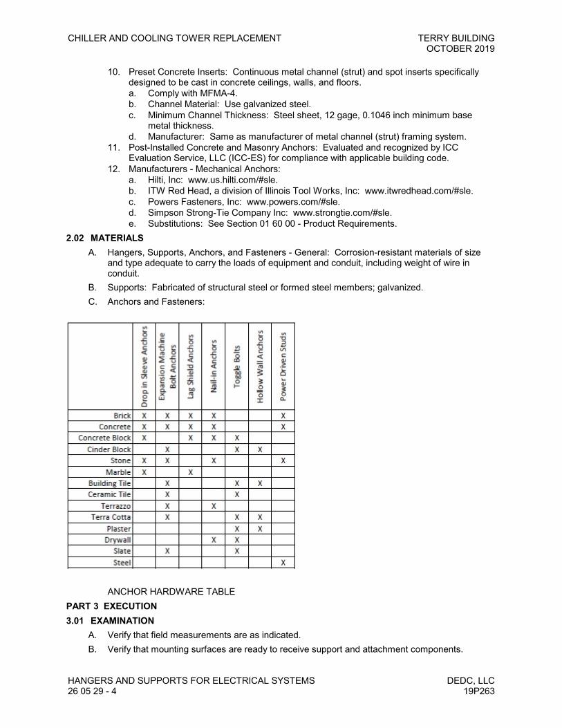
CHILLER AND COOLING TOWER REPLACEMENT TERRY BUILDINGOCTOBER 2019
HANGERS AND SUPPORTS FOR ELECTRICAL SYSTEMS DEDC, LLC26 05 29 - 4 19P263
10. Preset Concrete Inserts: Continuous metal channel (strut) and spot inserts specificallydesigned to be cast in concrete ceilings, walls, and floors.a. Comply with MFMA-4.b. Channel Material: Use galvanized steel.c. Minimum Channel Thickness: Steel sheet, 12 gage, 0.1046 inch minimum base
metal thickness.d. Manufacturer: Same as manufacturer of metal channel (strut) framing system.
11. Post-Installed Concrete and Masonry Anchors: Evaluated and recognized by ICCEvaluation Service, LLC (ICC-ES) for compliance with applicable building code.
12. Manufacturers - Mechanical Anchors:a. Hilti, Inc: www.us.hilti.com/#sle.b. ITW Red Head, a division of Illinois Tool Works, Inc: www.itwredhead.com/#sle.c. Powers Fasteners, Inc: www.powers.com/#sle.d. Simpson Strong-Tie Company Inc: www.strongtie.com/#sle.e. Substitutions: See Section 01 60 00 - Product Requirements.
2.02 MATERIALSA. Hangers, Supports, Anchors, and Fasteners - General: Corrosion-resistant materials of size
and type adequate to carry the loads of equipment and conduit, including weight of wire inconduit.
B. Supports: Fabricated of structural steel or formed steel members; galvanized.C. Anchors and Fasteners:
ANCHOR HARDWARE TABLEPART 3 EXECUTION3.01 EXAMINATION
A. Verify that field measurements are as indicated.B. Verify that mounting surfaces are ready to receive support and attachment components.

TERRY BUILDING CHILLER AND COOLING TOWER REPLACEMENTOCTOBER 2019
DEDC, LLC HANGERS AND SUPPORTS FOR ELECTRICAL SYSTEMS19P263 26 05 29 - 5
C. Verify that conditions are satisfactory for installation prior to starting work.3.02 INSTALLATION
A. Install products in accordance with manufacturer's instructions.B. Perform work in accordance with NECA 1 (general workmanship).C. Install anchors and fasteners in accordance with ICC Evaluation Services, LLC (ICC-ES)
evaluation report conditions of use where applicable.D. Provide independent support from building structure. Do not provide support from piping,
ductwork, or other systems.E. Unless specifically indicated or approved by DEDC, LLC, do not provide support from
suspended ceiling support system or ceiling grid.F. Unless specifically indicated or approved by DEDC, LLC, do not provide support from roof deck.G. Do not penetrate or otherwise notch or cut structural members without approval of Structural
Engineer.H. Equipment Support and Attachment:
1. Use metal fabricated supports or supports assembled from metal channel (strut) tosupport equipment as required.
2. Use metal channel (strut) secured to studs to support equipment surface-mounted onhollow stud walls when wall strength is not sufficient to resist pull-out.
3. Use metal channel (strut) to support surface-mounted equipment in wet or damp locationsto provide space between equipment and mounting surface.
4. Unless otherwise indicated, mount floor-mounted equipment on properly sized 3 inch highconcrete pad constructed in accordance with Section 03 30 00.
5. Securely fasten floor-mounted equipment. Do not install equipment such that it relies on itsown weight for support.
I. Conduit Support and Attachment: Also comply with Section 26 05 33.13.J. Box Support and Attachment: Also comply with Section 26 05 33.16.K. Preset Concrete Inserts: Use manufacturer provided closure strips to inhibit concrete seepage
during concrete pour.L. Secure fasteners according to manufacturer's recommended torque settings.M. Remove temporary supports.N. Identify independent electrical component support wires above accessible ceilings with color
distinguishable from ceiling support wires in accordance with NFPA 70.3.03 FIELD QUALITY CONTROL
A. See Section 01 40 00 - Quality Requirements, for additional requirements.B. Inspect support and attachment components for damage and defects.C. Repair cuts and abrasions in galvanized finishes using zinc-rich paint recommended by
manufacturer. Replace components that exhibit signs of corrosion.D. Correct deficiencies and replace damaged or defective support and attachment components.E. Install hangers and supports as required to adequately and securely support electrical system
components, in a neat and workmanlike manner, as specified in NECA 1.1. Do not fasten supports to pipes, ducts, mechanical equipment, or conduit.2. Do not drill or cut structural members.
F. Rigidly weld support members or use hexagon-head bolts to present neat appearance withadequate strength and rigidity. Use spring lock washers under all nuts.
G. Install surface-mounted cabinets and panelboards with minimum of four anchors.H. In wet and damp locations use steel channel supports to stand cabinets and panelboards 1-5/8"
off wall.

CHILLER AND COOLING TOWER REPLACEMENT TERRY BUILDINGOCTOBER 2019
HANGERS AND SUPPORTS FOR ELECTRICAL SYSTEMS DEDC, LLC26 05 29 - 6 19P263
I. Use sheet metal channel to bridge studs above and below cabinets and panelboards recessedin hollow partitions.
END OF SECTION

TERRY BUILDING CHILLER AND COOLING TOWER REPLACEMENTOCTOBER 2019
DEDC, LLC CONDUIT FOR ELECTRICAL SYSTEMS19P263 26 05 33.13 - 1
SECTION 26 05 33.13CONDUIT FOR ELECTRICAL SYSTEMS
PART 1 GENERAL1.01 SECTION INCLUDES
A. Galvanized steel rigid metal conduit (RMC).B. Aluminum rigid metal conduit (RMC).C. PVC-coated galvanized steel rigid metal conduit (RMC).D. Flexible metal conduit (FMC).E. Liquidtight flexible metal conduit (LFMC).F. Electrical metallic tubing (EMT).G. Rigid polyvinyl chloride (PVC) conduit.H. Conduit fittings.I. Accessories.J. Conduit, fittings and conduit bodies.
1.02 RELATED REQUIREMENTSA. Section 07 84 00 - Firestopping.B. Section 26 05 26 - Grounding and Bonding for Electrical Systems.
1. Includes additional requirements for fittings for grounding and bonding.C. Section 26 05 29 - Hangers and Supports for Electrical Systems.D. Section 26 05 33.16 - Boxes for Electrical Systems.E. Section 26 05 48 - Vibration and Seismic Controls for Electrical Systems.F. Section 26 05 53 - Identification for Electrical Systems: Identification products and
requirements.G. Section 31 23 16.13 - Trenching: Excavating, bedding, and backfilling.
1.03 REFERENCE STANDARDSA. ANSI C80.1 - American National Standard for Electrical Rigid Steel Conduit (ERSC); 2005.B. ANSI C80.3 - American National Standard for Steel Electrical Metallic Tubing (EMT); 2005.C. ANSI C80.5 - American National Standard for Electrical Rigid Aluminum Conduit (ERAC); 2005.D. NECA 1 - Standard for Good Workmanship in Electrical Construction; 2010.E. NECA 101 - Standard for Installing Steel Conduits (Rigid, IMC, EMT); 2013.F. NECA 102 - Standard for Installing Aluminum Rigid Metal Conduit; 2004.G. NECA 111 - Standard for Installing Nonmetallic Raceways (RNC, ENT, LFNC); 2003.H. NEMA FB 1 - Fittings, Cast Metal Boxes, and Conduit Bodies for Conduit, Electrical Metallic
Tubing, and Cable; 2012.I. NEMA RN 1 - Polyvinyl-Chloride (PVC) Externally Coated Galvanized Rigid Steel Conduit and
Intermediate Metal Conduit; 2005.J. NEMA TC 2 - Electrical Polyvinyl Chloride (PVC) Conduit; 2013.K. NEMA TC 3 - Polyvinyl Chloride (PVC) Fittings for Use with Rigid PVC Conduit and Tubing;
2015.L. NFPA 70 - National Electrical Code; Most Recent Edition Adopted by Authority Having
Jurisdiction, Including All Applicable Amendments and Supplements.M. UL 1 - Flexible Metal Conduit; Current Edition, Including All Revisions.N. UL 6 - Electrical Rigid Metal Conduit-Steel; Current Edition, Including All Revisions.
CHILLER AND COOLING TOWER REPLACEMENT TERRY BUILDINGOCTOBER 2019
CONDUIT FOR ELECTRICAL SYSTEMS DEDC, LLC26 05 33.13 - 2 19P263
O. UL 6A - Electrical Rigid Metal Conduit-Aluminum, Red Brass, and Stainless Steel; CurrentEdition, Including All Revisions.
P. UL 360 - Liquid-Tight Flexible Steel Conduit; Current Edition, Including All Revisions.Q. UL 514B - Conduit, Tubing, and Cable Fittings; Current Edition, Including All Revisions.R. UL 651 - Schedule 40, 80, Type EB and A Rigid PVC Conduit and Fittings; Current Edition,
Including All Revisions.S. UL 797 - Electrical Metallic Tubing-Steel; Current Edition, Including All Revisions.
1.04 ADMINISTRATIVE REQUIREMENTSA. Coordination:
1. Coordinate minimum sizes of conduits with the actual conductors to be installed, includingadjustments for conductor sizes increased for voltage drop.
2. Coordinate the arrangement of conduits with structural members, ductwork, piping,equipment and other potential conflicts installed under other sections or by others.
3. Verify exact conduit termination locations required for boxes, enclosures, and equipmentinstalled under other sections or by others.
4. Coordinate the work with other trades to provide roof penetrations that preserve theintegrity of the roofing system and do not void the roof warranty.
5. Notify DEDC, LLC of any conflicts with or deviations from Contract Documents. Obtaindirection before proceeding with work.
B. Sequencing:1. Do not begin installation of conductors and cables until installation of conduit is complete
between outlet, junction and splicing points.1.05 SUBMITTALS
A. See Section 01 30 00 - Administrative Requirements for submittals procedures.B. Product Data: Provide manufacturer's standard catalog pages and data sheets for conduits and
fittings.C. Project Record Documents: Record actual routing for conduits 2 inch (53 mm) trade size and
larger.1.06 QUALITY ASSURANCE
A. Conform to requirements of NFPA 70.B. Maintain at the project site a copy of each referenced document that prescribes execution
requirements.C. Product Listing Organization Qualifications: An organization recognized by OSHA as a
Nationally Recognized Testing Laboratory (NRTL) and acceptable to authorities havingjurisdiction.
1.07 DELIVERY, STORAGE, AND HANDLINGA. Receive, inspect, handle, and store conduit and fittings in accordance with manufacturer's
instructions.B. Accept conduit on site. Inspect for damage.C. Protect conduit from corrosion and entrance of debris by storing above grade. Provide
appropriate covering.PART 2 PRODUCTS2.01 CONDUIT APPLICATIONS
A. Do not use conduit and associated fittings for applications other than as permitted by NFPA 70and product listing.
B. Unless otherwise indicated and where not otherwise restricted, use the conduit types indicatedfor the specified applications. Where more than one listed application applies, comply with the

TERRY BUILDING CHILLER AND COOLING TOWER REPLACEMENTOCTOBER 2019
DEDC, LLC CONDUIT FOR ELECTRICAL SYSTEMS19P263 26 05 33.13 - 3
most restrictive requirements. Where conduit type for a particular application is not specified,use galvanized steel rigid metal conduit.
C. Underground:1. Under Slab on Grade: Use rigid PVC conduit.2. Exterior, Direct-Buried: Use rigid PVC conduit.3. Exterior, Embedded Within Concrete: Use rigid PVC conduit.4. Where rigid polyvinyl (PVC) conduit is provided, transition to galvanized steel rigid metal
conduit where emerging from underground.5. Where rigid polyvinyl (PVC) conduit larger than 2 inch (53 mm) trade size is provided, use
galvanized steel rigid metal conduit elbows for bends.6. Where steel conduit is installed in direct contact with earth where soil has a resistivity of
less than 2000 ohm-centimeters or is characterized as severely corrosive based on soilsreport or local experience, use corrosion protection tape to provide supplementarycorrosion protection or use PVC-coated galvanized steel rigid metal conduit.
7. Where steel conduit emerges from concrete into soil, use corrosion protection tape toprovide supplementary corrosion protection for a minimum of 4 inches on either side ofwhere conduit emerges or use PVC-coated galvanized steel rigid metal conduit.
D. Embedded Within Concrete:1. Within Slab on Grade: Use rigid PVC conduit.2. Within Slab Above Ground (within structural slabs only where approved by Structural
Engineer): Use rigid PVC conduit.3. Within Concrete Walls Above Ground: Use rigid PVC conduit.4. Where rigid polyvinyl (PVC) conduit is provided, transition to galvanized steel rigid metal
conduit where emerging from concrete.E. Concealed Within Masonry Walls: Use electrical metallic tubing (EMT).F. Concealed Within Hollow Stud Walls: Use electrical metallic tubing (EMT).G. Concealed Above Accessible Ceilings: Use electrical metallic tubing (EMT).H. Interior, Damp or Wet Locations: Use galvanized steel rigid metal conduit.I. Exposed, Interior (including unfinished spaces), Not Subject to Physical Damage: Use electrical
metallic tubing (EMT).J. Exposed, Interior (including unfinished spaces), Subject to Physical Damage: Use galvanized
steel rigid metal conduit.1. Locations subject to physical damage include, but are not limited to:
a. Where exposed below 8 feet, except within electrical and communication rooms orclosets.
b. Where exposed below 20 feet in warehouse areas.K. Exposed, Exterior: Use galvanized steel rigid metal conduit.L. Concealed, Exterior, Not Embedded in Concrete or in Contact With Earth: Use galvanized steel
rigid metal conduit.M. Corrosive Locations Above Ground: Use PVC-coated galvanized steel rigid metal conduit or
aluminum rigid metal conduit.1. Corrosive locations include, but are not limited to:
a. Cooling towers.N. Connections to Vibrating Equipment:
1. Dry Locations: Use flexible metal conduit.2. Damp, Wet, or Corrosive Locations: Use liquidtight flexible metal conduit.3. Maximum Length: 18 inches unless otherwise indicated.4. Vibrating equipment includes, but is not limited to:
a. Transformers.b. Motors.
O. Fished in Existing Walls, Where Necessary: Use flexible metal conduit.

CHILLER AND COOLING TOWER REPLACEMENT TERRY BUILDINGOCTOBER 2019
CONDUIT FOR ELECTRICAL SYSTEMS DEDC, LLC26 05 33.13 - 4 19P263
2.02 CONDUIT REQUIREMENTSA. Fittings for Grounding and Bonding: Also comply with Section 26 05 26.B. Provide all conduit, fittings, supports, and accessories required for a complete raceway system.C. Provide products listed, classified, and labeled as suitable for the purpose intended.D. Minimum Conduit Size, Unless Otherwise Indicated:
1. Branch Circuits: 3/4 inch (21 mm) trade size.2. Branch Circuit Homeruns: 3/4 inch (21 mm) trade size.3. Control Circuits: 1/2 inch (16 mm) trade size.4. Underground, Exterior: 1 inch (27 mm) trade size.
E. Where conduit size is not indicated, size to comply with NFPA 70 but not less than applicableminimum size requirements specified.
2.03 GALVANIZED STEEL RIGID METAL CONDUIT (RMC)A. Manufacturers:
1. Allied Tube & Conduit: www.alliedeg.com/#sle.2. Republic Conduit: www.republic-conduit.com/#sle.3. Wheatland Tube, a Division of Zekelman Industries: www.wheatland.com/#sle.4. Substitutions: See Section 01 60 00 - Product Requirements.
B. Description: NFPA 70, Type RMC galvanized steel rigid metal conduit complying with ANSIC80.1 and listed and labeled as complying with UL 6.
C. Fittings:1. Manufacturers:
a. Bridgeport Fittings Inc: www.bptfittings.com/#sle.b. O-Z/Gedney, a brand of Emerson Electric Co: www.emerson.com/#sle.c. Thomas & Betts Corporation: www.tnb.com/#sle.d. Substitutions: See Section 01 60 00 - Product Requirements.
2. Non-Hazardous Locations: Use fittings complying with NEMA FB 1 and listed and labeledas complying with UL 514B.
3. Material: Use steel or malleable iron.a. Do not use die cast zinc fittings.
4. Connectors and Couplings: Use threaded type fittings only. Threadless set screw andcompression (gland) type fittings are not permitted.
2.04 ALUMINUM RIGID METAL CONDUIT (RMC)A. Manufacturers:
1. Allied Tube & Conduit: www.alliedeg.com/#sle.2. Republic Conduit: www.republic-conduit.com/#sle.3. Wheatland Tube, a Division of Zekelman Industries: www.wheatland.com/#sle.4. Substitutions: See Section 01 60 00 - Product Requirements.
B. Description: NFPA 70, Type RMC aluminum rigid metal conduit complying with ANSI C80.5and listed and labeled as complying with UL 6A.
C. Fittings:1. Manufacturers:
a. Bridgeport Fittings Inc: www.bptfittings.com/#sle.b. O-Z/Gedney, a brand of Emerson Electric Co: www.emerson.com/#sle.c. Thomas & Betts Corporation: www.tnb.com/#sle.d. Substitutions: See Section 01 60 00 - Product Requirements.
2. Non-Hazardous Locations: Use fittings complying with NEMA FB 1 and listed and labeledas complying with UL 514B.
3. Material: Use aluminum.4. Connectors and Couplings: Use threaded type fittings only. Threadless set screw and
compression (gland) type fittings are not permitted.

TERRY BUILDING CHILLER AND COOLING TOWER REPLACEMENTOCTOBER 2019
DEDC, LLC CONDUIT FOR ELECTRICAL SYSTEMS19P263 26 05 33.13 - 5
2.05 PVC-COATED GALVANIZED STEEL RIGID METAL CONDUIT (RMC)A. Manufacturers:
1. Thomas & Betts Corporation: www.tnb.com.2. Robroy Industries: www.robroy.com.3. Substitutions: See Section 01 60 00 - Product Requirements.
B. Description: NFPA 70, Type RMC galvanized steel rigid metal conduit with external polyvinylchloride (PVC) coating complying with NEMA RN 1 and listed and labeled as complying with UL6.
C. Exterior Coating: Polyvinyl chloride (PVC), nominal thickness of 40 mil.D. PVC-Coated Fittings:
1. Manufacturer: Same as manufacturer of PVC-coated conduit to be installed.2. Non-Hazardous Locations: Use fittings listed and labeled as complying with UL 514B.3. Material: Use steel or malleable iron.4. Exterior Coating: Polyvinyl chloride (PVC), minimum thickness of 40 mil.
E. PVC-Coated Supports: Furnish with exterior coating of polyvinyl chloride (PVC), minimumthickness of 15 mil.
2.06 FLEXIBLE METAL CONDUIT (FMC)A. Manufacturers:
1. AFC Cable Systems, Inc: www.afcweb.com.2. Electri-Flex Company: www.electriflex.com.3. International Metal Hose: www.metalhose.com.4. Substitutions: See Section 01 60 00 - Product Requirements.
B. Description: NFPA 70, Type FMC standard wall steel flexible metal conduit listed and labeledas complying with UL 1, and listed for use in classified firestop systems to be used.
C. Fittings:1. Manufacturers:
a. Bridgeport Fittings Inc: www.bptfittings.com/#sle.b. O-Z/Gedney, a brand of Emerson Electric Co: www.emerson.com/#sle.c. Thomas & Betts Corporation: www.tnb.com/#sle.d. Substitutions: See Section 01 60 00 - Product Requirements.
2. Description: Fittings complying with NEMA FB 1 and listed and labeled as complying withUL 514B.
3. Material: Use steel or malleable iron.a. Do not use die cast zinc fittings.
D. Description: Interlocked steel construction.E. Fittings: NEMA FB 1.
2.07 LIQUIDTIGHT FLEXIBLE METAL CONDUIT (LFMC)A. Manufacturers:
1. AFC Cable Systems, Inc: www.afcweb.com.2. Electri-Flex Company: www.electriflex.com.3. International Metal Hose: www.metalhose.com.4. Substitutions: See Section 01 60 00 - Product Requirements.
B. Description: NFPA 70, Type LFMC polyvinyl chloride (PVC) jacketed steel flexible metal conduitlisted and labeled as complying with UL 360.
C. Fittings:1. Manufacturers:
a. Bridgeport Fittings Inc: www.bptfittings.com/#sle.b. O-Z/Gedney, a brand of Emerson Electric Co: www.emerson.com/#sle.c. Thomas & Betts Corporation: www.tnb.com/#sle.

CHILLER AND COOLING TOWER REPLACEMENT TERRY BUILDINGOCTOBER 2019
CONDUIT FOR ELECTRICAL SYSTEMS DEDC, LLC26 05 33.13 - 6 19P263
d. Substitutions: See Section 01 60 00 - Product Requirements.2. Description: Fittings complying with NEMA FB 1 and listed and labeled as complying with
UL 514B.3. Material: Use steel or malleable iron.
a. Do not use die cast zinc fittings.D. Description: Interlocked steel construction with PVC jacket.E. Fittings: NEMA FB 1.
2.08 ELECTRICAL METALLIC TUBING (EMT)A. Manufacturers:
1. Allied Tube & Conduit: www.alliedeg.com.2. Republic Conduit: www.republic-conduit.com/#sle.3. Wheatland Tube Company: www.wheatland.com.4. Triangle5. Substitutions: See Section 01 60 00 - Product Requirements.
B. Description: NFPA 70, Type EMT steel electrical metallic tubing complying with ANSI C80.3and listed and labeled as complying with UL 797.
C. Fittings:1. Manufacturers:
a. Bridgeport Fittings Inc: www.bptfittings.com/#sle.b. O-Z/Gedney, a brand of Emerson Electric Co: www.emerson.com/#sle.c. Thomas & Betts Corporation: www.tnb.com/#sle.d. Substitutions: See Section 01 60 00 - Product Requirements.
2. Description: Fittings complying with NEMA FB 1 and listed and labeled as complying withUL 514B.
3. Material: Use steel or malleable iron.a. Do not use die cast zinc fittings.
4. Connectors and Couplings: Use compression (gland) type.a. Do not use indenter type connectors and couplings.b. Do not use set-screw type connectors and couplings.
D. Description: ANSI C80.3; galvanized tubing.E. Fittings and Conduit Bodies: NEMA FB 1; steel or malleable iron compression type.
2.09 RIGID POLYVINYL CHLORIDE (PVC) CONDUITA. Manufacturers:
1. Cantex Inc: www.cantexinc.com/#sle.2. Carlon, a brand of Thomas & Betts Corporation: www.carlon.com/#sle.3. JM Eagle: www.jmeagle.com/#sle.4. Substitutions: See Section 01 60 00 - Product Requirements.
B. Description: NFPA 70, Type PVC rigid polyvinyl chloride conduit complying with NEMA TC 2and listed and labeled as complying with UL 651; Schedule 80 unless otherwise indicated; ratedfor use with conductors rated 90 degrees C.
C. Fittings:1. Manufacturer: Same as manufacturer of conduit to be connected.2. Description: Fittings complying with NEMA TC 3 and listed and labeled as complying with
UL 651; material to match conduit.2.10 ACCESSORIES
A. Corrosion Protection Tape: PVC-based, minimum thickness of 20 mil.B. Conduit Joint Compound: Corrosion-resistant, electrically conductive; suitable for use with the
conduit to be installed.
TERRY BUILDING CHILLER AND COOLING TOWER REPLACEMENTOCTOBER 2019
DEDC, LLC CONDUIT FOR ELECTRICAL SYSTEMS19P263 26 05 33.13 - 7
C. Solvent Cement for PVC Conduit and Fittings: As recommended by manufacturer of conduitand fittings to be installed.
D. Pull Strings: Use nylon cord or 14 AWG zinc-coated steel with average breaking strength of notless than 200 pound-force.
E. Sealing Compound for Sealing Fittings: Listed for use with the particular fittings to be installed.F. Modular Seals for Conduit Penetrations: Rated for minimum of 40 psig; Suitable for the
conduits to be installed.1. Product: Link-Seal.2. Substitutions: See Section 01 60 00 - Product Requirements.
PART 3 EXECUTION3.01 EXAMINATION
A. Verify that field measurements are as indicated.B. Verify that mounting surfaces are ready to receive conduits.C. Verify that conditions are satisfactory for installation prior to starting work.D. Conduit routing is shown on drawings in approximate locations unless dimensioned. Route as
required to complete wiring system.3.02 INSTALLATION
A. Install products in accordance with manufacturer's instructions.B. All conduit penetrations into equipment enclosures shall be made by the Electrical Contractor.C. Install conduit securely in a neat and workmanlike manner in accordance with NECA 1.D. Install galvanized steel rigid metal conduit (RMC) in accordance with NECA 101.E. Install aluminum rigid metal conduit (RMC) in accordance with NECA 102.F. Install PVC-coated galvanized steel rigid metal conduit (RMC) using only tools approved by the
manufacturer.G. Install rigid polyvinyl chloride (PVC) conduit in accordance with NECA 111.H. Conduit Routing:
1. Unless dimensioned, conduit routing indicated is diagrammatic.2. When conduit destination is indicated without specific routing, determine exact routing
required.3. Conceal all conduits within finished walls, ceilings and floors unless specifically indicated to
be exposed.4. Conduits in the following areas may be exposed, unless otherwise indicated:
a. Electrical rooms.b. Mechanical equipment rooms.c. Within joists in areas with no ceiling.
5. Unless otherwise approved, do not route conduits exposed:a. Across floors.b. Across roofs.c. Across top of parapet walls.d. Across building exterior surfaces.
6. Conduits installed underground or embedded in concrete may be routed in the shortestpossible manner unless otherwise indicated. Route all other conduits parallel orperpendicular to building structure and surfaces, following surface contours wherepractical.
7. Arrange conduit to maintain adequate headroom, clearances, and access.8. Arrange conduit to provide no more than the equivalent of four 90 degree bends between
pull points. Use conduit bodies to make sharp changes in direction, as around beams. Usehydraulic one-shot bender to fabricate bends in metal conduit larger than 2 inch size.
9. Arrange conduit to provide no more than 150 feet between pull points.

CHILLER AND COOLING TOWER REPLACEMENT TERRY BUILDINGOCTOBER 2019
CONDUIT FOR ELECTRICAL SYSTEMS DEDC, LLC26 05 33.13 - 8 19P263
10. Route conduits above water and drain piping where possible.11. Arrange conduit to prevent moisture traps. Provide drain fittings at low points and at
sealing fittings where moisture may collect.12. Maintain minimum clearance of 6 inches between conduits and piping for other systems.13. Maintain minimum clearance of 12 inches between conduits and hot surfaces. This
includes, but is not limited to:a. Heaters.b. Hot water piping.c. Flues.
14. Group parallel conduits in the same area together on a common rack.I. Conduit Support:
1. Secure and support conduits in accordance with NFPA 70 and Section 26 05 29 usingsuitable supports and methods approved by the authority having jurisdiction.
2. Provide independent support from building structure. Do not provide support from piping,ductwork, or other systems.
3. Installation Above Suspended Ceilings: Do not provide support from ceiling supportsystem. Do not provide support from ceiling grid or allow conduits to lay on ceiling tiles.
4. Use conduit strap to support single surface-mounted conduit.a. Use clamp back spacer with conduit strap for damp and wet locations to provide
space between conduit and mounting surface.5. Use metal channel (strut) with accessory conduit clamps to support multiple parallel
surface-mounted conduits.6. Use conduit clamp to support single conduit from beam clamp or threaded rod.7. Use trapeze hangers assembled from threaded rods and metal channel (strut) with
accessory conduit clamps to support multiple parallel suspended conduits.8. Use non-penetrating rooftop supports to support conduits routed across rooftops (only
where approved). All such conduits shall be elevated a minimum of 12 inches above therooftop where exposed to direct sunlight.
9. Use of spring steel conduit clips for support of conduits is not permitted.10. Use of wire for support of conduits is not permitted. Remove all wire used for temporary
supports.11. Use of perforated pipe straps for support of conduits is not permitted.12. Where conduit support intervals specified in NFPA 70 and NECA standards differ, comply
with the most stringent requirements.J. Connections and Terminations:
1. Use fittings compatible with conduit used and suitable for location.2. Use approved zinc-rich paint or conduit joint compound on field-cut threads of galvanized
steel conduits prior to making connections.3. Where two threaded conduits must be joined and neither can be rotated, use three-piece
couplings or split couplings. Do not use running threads.4. Use suitable adapters where required to transition from one type of conduit to another.5. Provide drip loops for liquidtight flexible conduit connections to prevent drainage of liquid
into connectors.6. Terminate threaded conduits in boxes and enclosures using threaded hubs or double lock
nuts for dry locations and raintight hubs for wet locations.7. Provide insulating bushings or insulated throats at all conduit terminations to protect
conductors.8. Bring conduit to shoulders of fittings. Secure joints and connections tightly to provide
maximum mechanical strength and electrical continuity. Use bonding bushings or wedgesat connections subject to vibration.
K. Penetrations:1. Do not penetrate or otherwise notch or cut structural members, including footings and
grade beams, without approval of Structural Engineer.
TERRY BUILDING CHILLER AND COOLING TOWER REPLACEMENTOCTOBER 2019
DEDC, LLC CONDUIT FOR ELECTRICAL SYSTEMS19P263 26 05 33.13 - 9
2. All penetrations through floors or walls shall be core-drilled. Use of jack hammers shall notbe permitted. Maximum hole diameters shall not exceed 6 inches. All holes shall bespaced at least 18 inches apart in all directions. Re-use of existing penetrations shall bepermitted.
3. Prior to any core drilling through floors or walls, the Electrical Contractor shall visuallysurvey both sides to determine if any pipes, ducts or electrical utilities exist that maypresent obstacles. The Electrical Contractor shall also indentify locations of existingconcrete slab reinforcement or in-slab utilities using a pachometer, x-ray or similar device.All core-drilled penetrations shall be a minimum of 3 inches away from existing concreteslab reinforcement or in-slab utilities.
4. Make penetrations perpendicular to surfaces unless otherwise indicated.5. Provide steel sleeves for penetrations as indicated or as required to facilitate installation.
Set sleeves flush with exposed surfaces unless otherwise indicated or required.6. Conceal bends for conduit risers emerging above ground.7. Seal interior of conduits entering the building from underground at first accessible point to
prevent entry of moisture and gases.8. Provide suitable modular seal where conduits penetrate exterior wall below grade.9. Where conduits penetrate waterproof membrane, seal as required to maintain integrity of
membrane.10. Make penetrations for roof-mounted equipment within associated equipment openings and
curbs where possible to minimize roofing system penetrations. Where penetrations arenecessary, seal as indicated or as required to preserve integrity of roofing system andmaintain roof warranty. Include proposed locations of penetrations and methods for sealingwith submittals.
11. Provide metal escutcheon plates for conduit penetrations exposed to public view.12. Install firestopping to preserve fire resistance rating of partitions and other elements, using
materials and methods specified in Section 07 84 00.L. Stub-Up Connections for Equipment: Extend conductors to equipment with rigid metal conduit
(RMC). Flexible metal conduit (FMC) or liquidtight flexible metal conduit (LFMC) may be used 6inches above the floor.
M. Underground Installation:1. Provide trenching and backfilling in accordance with Section 31 23 16.13.2. Minimum Cover, Unless Otherwise Indicated or Required:
a. Underground, Exterior: 36 inches.b. Under Slab on Grade: 36 inches to bottom of slab.
3. Provide underground warning tape in accordance with Section 26 05 53 along entireconduit length.
N. Embedment Within Structural Concrete Slabs:1. Secure conduits to prevent floating or movement during pouring of concrete.
O. Conduit Movement Provisions: Where conduits are subject to movement, provide expansionand expansion/deflection fittings or approved flexible connections to prevent damage toenclosed conductors or connected equipment. This includes, but is not limited to:1. Where conduits cross structural joints intended for expansion, contraction, or deflection.2. Where conduits are subject to earth movement by settlement or frost.
P. Condensation Prevention: Where conduits cross barriers between areas of potential substantialtemperature differential, provide conduit sealing fittings filled with listed sealing compound atapproved and accessible locations near the penetrations to prevent condensation. Forconcealed conduits, install each fitting in a flush steel box with blank cover plate having finishsimilar to that of adjacent plates or surfaces. This includes, but is not limited to:1. Where conduits pass from outdoors into conditioned interior spaces.2. Where conduits pass from unconditioned interior spaces into conditioned interior spaces.3. Where conduits penetrate coolers or freezers, or other refrigerated spaces.

CHILLER AND COOLING TOWER REPLACEMENT TERRY BUILDINGOCTOBER 2019
CONDUIT FOR ELECTRICAL SYSTEMS DEDC, LLC26 05 33.13 - 10 19P263
Q. Provide pull string in all empty conduits and in conduits where conductors and cables are to beinstalled by others. Leave minimum slack of 12 inches at each end.
R. Provide grounding and bonding of conduit in accordance with Section 26 05 26.S. Identify conduits in accordance with Section 26 05 53.
3.03 FIELD QUALITY CONTROLA. See Section 01 40 00 - Quality Requirements, for additional requirements.B. Repair cuts and abrasions in galvanized finishes using zinc-rich paint recommended by
manufacturer. Replace components that exhibit signs of corrosion.C. Where coating of PVC-coated galvanized steel rigid metal conduit (RMC) contains cuts or
abrasions, repair in accordance with manufacturer's instructions.D. Correct deficiencies and replace damaged or defective conduits.
3.04 CLEANINGA. Clean interior of conduits to remove moisture and foreign matter.
3.05 PROTECTIONA. Immediately after installation of conduit, use suitable manufactured plugs to provide protection
from entry of moisture and foreign material and do not remove until ready for installation ofconductors.
B. Arrange supports to prevent misalignment during wiring installation.C. Cut conduit square using saw or pipecutter; de-burr cut ends.D. Use suitable caps to protect installed conduit against entrance of dirt and moisture.
3.06 INTERFACE WITH OTHER PRODUCTSA. Install conduit to preserve fire resistance rating of partitions and other elements, using materials
and methods specified in Section 07 84 00.END OF SECTION
TERRY BUILDING CHILLER AND COOLING TOWER REPLACEMENTOCTOBER 2019
DEDC, LLC BOXES FOR ELECTRICAL SYSTEMS19P263 26 05 33.16 - 1
SECTION 26 05 33.16BOXES FOR ELECTRICAL SYSTEMS
PART 1 GENERAL1.01 SECTION INCLUDES
A. Outlet and device boxes up to 100 cubic inches, including those used as junction and pullboxes.
B. Cabinets and enclosures, including junction and pull boxes larger than 100 cubic inches.1.02 RELATED REQUIREMENTS
A. Section 07 84 00 - Firestopping.B. Section 26 05 26 - Grounding and Bonding for Electrical Systems.C. Section 26 05 29 - Hangers and Supports for Electrical Systems.D. Section 26 05 33.13 - Conduit for Electrical Systems:
1. Conduit bodies and other fittings.2. Additional requirements for locating boxes to limit conduit length and/or number of bends
between pulling points.E. Section 26 05 53 - Identification for Electrical Systems: Identification products and
requirements.F. Section 26 27 26 - Wiring Devices:
1. Wall plates.2. Additional requirements for locating boxes for wiring devices.
1.03 REFERENCE STANDARDSA. NECA 1 - Standard for Good Workmanship in Electrical Construction; 2010.B. NECA 130 - Standard for Installing and Maintaining Wiring Devices; 2010.C. NEMA FB 1 - Fittings, Cast Metal Boxes, and Conduit Bodies for Conduit, Electrical Metallic
Tubing, and Cable; 2012.D. NEMA OS 1 - Sheet-Steel Outlet Boxes, Device Boxes, Covers, and Box Supports; 2013.E. NEMA 250 - Enclosures for Electrical Equipment (1000 Volts Maximum); 2014.F. NFPA 70 - National Electrical Code; Most Recent Edition Adopted by Authority Having
Jurisdiction, Including All Applicable Amendments and Supplements.G. UL 50 - Enclosures for Electrical Equipment, Non-Environmental Considerations; Current
Edition, Including All Revisions.H. UL 50E - Enclosures for Electrical Equipment, Environmental Considerations; Current Edition,
Including All Revisions.I. UL 508A - Industrial Control Panels; Current Edition, Including All Revisions.J. UL 514A - Metallic Outlet Boxes; Current Edition, Including All Revisions.
1.04 ADMINISTRATIVE REQUIREMENTSA. Coordination:
1. Coordinate the work with other trades to avoid placement of ductwork, piping, equipment,or other potential obstructions within the dedicated equipment spaces and workingclearances for electrical equipment required by NFPA 70.
2. Coordinate arrangement of electrical equipment with the dimensions and clearancerequirements of the actual equipment to be installed.
3. Coordinate minimum sizes of boxes with the actual installed arrangement of conductors,clamps, support fittings, and devices, calculated according to NFPA 70.
4. Coordinate minimum sizes of pull boxes with the actual installed arrangement ofconnected conduits, calculated according to NFPA 70.
CHILLER AND COOLING TOWER REPLACEMENT TERRY BUILDINGOCTOBER 2019
BOXES FOR ELECTRICAL SYSTEMS DEDC, LLC26 05 33.16 - 2 19P263
5. Coordinate the placement of boxes with millwork, furniture, devices, equipment, etc.installed under other sections or by others.
6. Coordinate the work with other trades to preserve insulation integrity.7. Coordinate the work with other trades to provide walls suitable for installation of
flush-mounted boxes where indicated.8. Notify DEDC, LLC of any conflicts with or deviations from Contract Documents. Obtain
direction before proceeding with work.1.05 SUBMITTALS
A. See Section 01 30 00 - Administrative Requirements, for submittal procedures.B. Product Data: Provide manufacturer's standard catalog pages and data sheets for outlet and
device boxes and junction and pull boxes.C. Project Record Documents: Record actual locations for pull boxes.D. Maintenance Materials: Furnish the following for Owner's use in maintenance of project.
1. See Section 01 60 00 - Product Requirements, for additional provisions.1.06 QUALITY ASSURANCE
A. Conform to requirements of NFPA 70.B. Maintain at the project site a copy of each referenced document that prescribes execution
requirements.C. Product Listing Organization Qualifications: An organization recognized by OSHA as a
Nationally Recognized Testing Laboratory (NRTL) and acceptable to authorities havingjurisdiction.
1.07 DELIVERY, STORAGE, AND HANDLINGA. Receive, inspect, handle, and store products in accordance with manufacturer's instructions.
PART 2 PRODUCTS2.01 BOXES
A. General Requirements:1. Do not use boxes and associated accessories for applications other than as permitted by
NFPA 70 and product listing.2. Provide all boxes, fittings, supports, and accessories required for a complete raceway
system and to accommodate devices and equipment to be installed.3. Provide products listed, classified, and labeled as suitable for the purpose intended.4. Where box size is not indicated, size to comply with NFPA 70 but not less than applicable
minimum size requirements specified.5. Provide grounding terminals within boxes where equipment grounding conductors
terminate.B. Outlet and Device Boxes Up to 100 cubic inches, Including Those Used as Junction and Pull
Boxes:1. Use sheet-steel boxes for concealed interior dry locations unless otherwise indicated or
required.2. Use cast iron boxes or cast aluminum boxes for exposed interior dry locations, and for
interior and exterior damp or wet locations unless otherwise indicated or required; furnishwith compatible weatherproof gasketed covers.
3. Use cast iron boxes or cast aluminum boxes where exposed galvanized steel rigid metalconduit is used.
4. Use cast aluminum boxes where aluminum rigid metal conduit is used.5. Use suitable concrete type boxes where flush-mounted in concrete.6. Use suitable masonry type boxes where flush-mounted in masonry walls.7. Use raised covers suitable for the type of wall construction and device configuration where
required.8. Use shallow boxes where required by the type of wall construction.

TERRY BUILDING CHILLER AND COOLING TOWER REPLACEMENTOCTOBER 2019
DEDC, LLC BOXES FOR ELECTRICAL SYSTEMS19P263 26 05 33.16 - 3
9. Do not use "through-wall" boxes designed for access from both sides of wall.10. Sheet-Steel Boxes: Comply with NEMA OS 1, and list and label as complying with UL
514A.11. Cast Metal Boxes: Comply with NEMA FB 1, and list and label as complying with UL
514A; furnish with threaded hubs.12. Boxes for Supporting Luminaires and Ceiling Fans: Listed as suitable for the type and
weight of load to be supported; furnished with fixture stud to accommodate mounting ofluminaire where required.
13. Boxes for Ganged Devices: Use multigang boxes of single-piece construction. Do not usefield-connected gangable boxes unless specifically indicated or permitted.
14. Minimum Box Size, Unless Otherwise Indicated:a. Wiring Devices: 4 inch square by 2-1/8 inch deep (100 by 54 mm) trade size.
15. Wall Plates: Comply with Section 26 27 26.16. Manufacturers:
a. Cooper Crouse-Hinds, a division of Eaton Corporation: www.cooperindustries.com/#sle.
b. Hubbell Incorporated; Bell Products: www.hubbell-rtb.com.c. Hubbell Incorporated; RACO Products: www.hubbell-rtb.com.d. O-Z/Gedney, a brand of Emerson Electric Co: www.emerson.com/#sle.e. Thomas & Betts Corporation; Steel City Products: www.tnb.com/#sle.f. Substitutions: See Section 01 60 00 - Product Requirements.
C. Cabinets and Enclosures, Including Junction and Pull Boxes Larger Than 100 cubic inches:1. Comply with NEMA 250, and list and label as complying with UL 50 and UL 50E, or UL
508A.2. NEMA 250 Environment Type, Unless Otherwise Indicated:
a. Indoor Clean, Dry Locations: Type 1, painted steel.b. Outdoor Locations: Type 3R, painted steel.
3. Junction and Pull Boxes Larger Than 100 cubic inches:a. Provide screw-cover or hinged-cover enclosures unless otherwise indicated.
4. Finish for Painted Steel Enclosures: Manufacturer's standard grey unless otherwiseindicated.
5. Manufacturers:a. Cooper B-Line, a division of Eaton Corporation: www.cooperindustries.com/#sle.b. Hoffman, a brand of Pentair Technical Products: www.hoffmanonline.com/#sle.c. Hubbell Incorporated; Wiegmann Products: www.hubbell-wiegmann.com/#sle.d. Substitutions: See Section 01 60 00 - Product Requirements.
PART 3 EXECUTION3.01 EXAMINATION
A. Verify that field measurements are as indicated.B. Verify that mounting surfaces are ready to receive boxes.C. Verify that conditions are satisfactory for installation prior to starting work.D. Verify locations of floor boxes and outlets in offices and work areas prior to rough-in.
3.02 INSTALLATIONA. Install products in accordance with manufacturer's instructions.B. Install boxes in accordance with NECA 1 (general workmanship) and, where applicable, NECA
130, including mounting heights specified in those standards where mounting heights are notindicated.
C. Arrange equipment to provide minimum clearances in accordance with manufacturer'sinstructions and NFPA 70.
D. Unless otherwise indicated, provide separate boxes for line voltage and low voltage systems.

CHILLER AND COOLING TOWER REPLACEMENT TERRY BUILDINGOCTOBER 2019
BOXES FOR ELECTRICAL SYSTEMS DEDC, LLC26 05 33.16 - 4 19P263
E. Flush-mount boxes in finished areas unless specifically indicated to be surface-mounted.F. Unless otherwise indicated, boxes may be surface-mounted where exposed conduits are
indicated or permitted.G. Box Locations:
1. Unless dimensioned, box locations indicated are approximate.2. Locate and orient boxes as required for devices installed under other sections or by others.
a. Switches, Receptacles, and Other Wiring Devices: Comply with Section 26 27 26.3. Locate boxes so that wall plates do not span different building finishes.4. Locate boxes so that wall plates do not cross masonry joints.5. Unless otherwise indicated, where multiple outlet boxes are installed at the same location
at different mounting heights, install along a common vertical center line.6. Do not install flush-mounted boxes on opposite sides of walls back-to-back. Provide
minimum 6 inches horizontal separation unless otherwise indicated:a. Acoustic-Rated Walls: Do not install flush-mounted boxes on opposite sides of walls
back-to-back; provide minimum 24 inches horizontal separation.b. Fire Resistance Rated Walls: Install flush-mounted boxes such that the required fire
resistance will not be reduced.1) Do not install flush-mounted boxes on opposite sides of walls back-to-back;
provide minimum 24 inches separation where wall is constructed with individualnoncommunicating stud cavities or protect both boxes with listed putty pads.
2) Do not install flush-mounted boxes with area larger than 16 square inches orsuch that the total aggregate area of openings exceeds 100 square inches forany 100 square feet of wall area.
7. Locate junction and pull boxes as indicated, as required to facilitate installation ofconductors, and to limit conduit length and/or number of bends between pulling points inaccordance with Section 26 05 33.13.
8. Locate junction and pull boxes in the following areas, unless otherwise indicated orapproved by the Architect:a. Concealed above accessible suspended ceilings.b. Within joists in areas with no ceiling.c. Electrical rooms.d. Mechanical equipment rooms.
H. Box Supports:1. Secure and support boxes in accordance with NFPA 70 and Section 26 05 29 using
suitable supports and methods approved by the authority having jurisdiction.2. Provide independent support from building structure except for cast metal boxes (other
than boxes used for fixture support) supported by threaded conduit connections inaccordance with NFPA 70. Do not provide support from piping, ductwork, or othersystems.
3. Installation Above Suspended Ceilings: Do not provide support from ceiling grid or ceilingsupport system.
4. Use far-side support to secure flush-mounted boxes supported from single stud in hollowstud walls. Repair or replace supports for boxes that permit excessive movement.
I. Install boxes plumb and level.J. Flush-Mounted Boxes:
1. Install boxes in noncombustible materials such as concrete, tile, gypsum, plaster, etc. sothat front edge of box or associated raised cover is not set back from finished surfacemore than 1/4 inch or does not project beyond finished surface.
2. Install boxes in combustible materials such as wood so that front edge of box orassociated raised cover is flush with finished surface.
3. Repair rough openings around boxes in noncombustible materials such as concrete, tile,gypsum, plaster, etc. so that there are no gaps or open spaces greater than 1/8 inch at theedge of the box.

TERRY BUILDING CHILLER AND COOLING TOWER REPLACEMENTOCTOBER 2019
DEDC, LLC BOXES FOR ELECTRICAL SYSTEMS19P263 26 05 33.16 - 5
K. Install boxes as required to preserve insulation integrity.L. Install permanent barrier between ganged wiring devices when voltage between adjacent
devices exceeds 300 V.M. Install firestopping to preserve fire resistance rating of partitions and other elements, using
materials and methods specified in Section 07 84 00.N. Close unused box openings.O. Install blank wall plates on junction boxes and on outlet boxes with no devices or equipment
installed or designated for future use.P. Provide grounding and bonding of boxes, enclosures and cabinets in accordance with Section
26 05 26.Q. Identify boxes in accordance with Section 26 05 53.R. Install boxes securely, in a neat and workmanlike manner, as specified in NECA 1.S. Install in locations as shown on Drawings, and as required for splices, taps, wire pulling,
equipment connections, and as required by NFPA 70.T. Coordinate installation of outlet boxes for equipment connected under Section 26 27 17.U. Set wall mounted boxes at elevations to accommodate mounting heights indicated.V. Electrical boxes are shown on Drawings in approximate locations unless dimensioned.
1. Adjust box locations up to 10 feet if required to accommodate intended purpose.W. Maintain headroom and present neat mechanical appearance.X. Inaccessible Ceiling Areas: Install outlet and junction boxes no more than 6 inches from ceiling
access panel or from removable recessed luminaire.Y. Coordinate mounting heights and locations of outlets mounted above counters, benches, and
backsplashes.Z. Locate outlet boxes to allow luminaires to be positioned as shown on reflected ceiling plan.AA. Align adjacent wall mounted outlet boxes for switches, thermostats, and similar devices.AB. Locate flush mounting boxes in masonry walls to require cutting of masonry unit corner only.
Coordinate masonry cutting to achieve neat opening.AC. Secure flush mounting box to interior wall and partition studs. Accurately position to allow for
surface finish thickness.AD. Support boxes independently of conduit, except cast box that is connected to two rigid metal
conduits both supported within 12 inches of box.AE. Use gang box with plaster ring for single device outlets.
3.03 ADJUSTINGA. Adjust flush-mounting outlets to make front flush with finished wall material.B. Install knockout closures in unused box openings.
3.04 CLEANINGA. Clean interior of boxes to remove dirt, debris, plaster and other foreign material.
3.05 PROTECTIONA. Immediately after installation, protect boxes from entry of moisture and foreign material until
ready for installation of conductors.B. Clean exposed surfaces and restore finish.
END OF SECTION
CHILLER AND COOLING TOWER REPLACEMENT TERRY BUILDINGOCTOBER 2019
BOXES FOR ELECTRICAL SYSTEMS DEDC, LLC26 05 33.16 - 6 19P263
THIS PAGE INTENTIONALLY LEFT BLANK

TERRY BUILDING CHILLER AND COOLING TOWER REPLACEMENTOCTOBER 2019
DEDC, LLC IDENTIFICATION FOR ELECTRICAL SYSTEMS19P263 26 05 53 - 1
SECTION 26 05 53IDENTIFICATION FOR ELECTRICAL SYSTEMS
PART 1 GENERAL1.01 SECTION INCLUDES
A. Electrical identification requirements.B. Large Device Identification.C. Nameplates and Labels.D. Wire and cable markers.E. Voltage markers.F. Underground warning tape.G. Warning signs and labels.
1.02 RELATED REQUIREMENTSA. Section 26 05 19 - Low-Voltage Electrical Power Conductors and Cables: Color coding for
power conductors and cables 600 V and less; vinyl color coding electrical tape.1.03 REFERENCE STANDARDS
A. ANSI Z535.2 - American National Standard for Environmental and Facility Safety Signs; 2011.B. ANSI Z535.4 - American National Standard for Product Safety Signs and Labels; 2011.C. NFPA 70 - National Electrical Code; Most Recent Edition Adopted by Authority Having
Jurisdiction, Including All Applicable Amendments and Supplements.D. NFPA 70E - Standard for Electrical Safety in the Workplace; 2015.E. UL 969 - Marking and Labeling Systems; Current Edition, Including All Revisions.
1.04 ADMINISTRATIVE REQUIREMENTSA. Coordination:
1. Verify final designations for equipment, systems, and components to be identified prior tofabrication of identification products.
B. Sequencing:1. Do not conceal items to be identified, in locations such as above suspended ceilings, until
identification products have been installed.2. Do not install identification products until final surface finishes and painting are complete.
1.05 SUBMITTALSA. See Section 01 30 00 - Administrative Requirements for submittals procedures.B. Product Data: Provide manufacturer's standard catalog pages and data sheets for each
product.C. Shop Drawings: Provide schedule of items to be identified indicating proposed designations,
materials, legends, and formats.1.06 QUALITY ASSURANCE
A. Conform to requirements of NFPA 70.1.07 FIELD CONDITIONS
A. Do not install adhesive products when ambient temperature is lower than recommended bymanufacturer.
PART 2 PRODUCTS2.01 IDENTIFICATION REQUIREMENTS
A. Identification for Equipment:

CHILLER AND COOLING TOWER REPLACEMENT TERRY BUILDINGOCTOBER 2019
IDENTIFICATION FOR ELECTRICAL SYSTEMS DEDC, LLC26 05 53 - 2 19P263
1. Use identification nameplate to identify each piece of electrical distribution and controlequipment and associated sections, compartments, and components.a. Switchboards:
1) Use identification nameplate to identify load(s) served for each branch device.b. Panelboards:
1) Identify ampere rating.2) Identify voltage and phase.3) Identify power source and circuit number. Include location when not within sight
of equipment.4) Identify main overcurrent protective device. Use identification label for
panelboards with a door. For power distribution panelboards without a door, useidentification nameplate.
5) Use typewritten circuit directory to identify load(s) served for panelboards with adoor.
c. Enclosed switches, circuit breakers, and motor controllers:1) Identify voltage and phase.2) Identify power source and circuit number. Include location when not within sight
of equipment.3) Identify load(s) served. Include location when not within sight of equipment.
2. Use voltage marker to identify highest voltage present for each piece of electricalequipment with nominal voltage equal to or greater than 480 V phase-to-phase and 277 Vphase-to-ground.
3. Use identification nameplate to identify disconnect location for equipment with remotedisconnecting means.
4. Available Fault Current Documentation: Use identification label to identify the availablefault current and date calculations were performed at locations requiring documentation byNFPA 70, including but not limited to the following.a. Service equipment.b. Industrial control panels.c. Motor control centers.d. Elevator control panels.e. Industrial machinery.
5. Arc Flash Hazard Warning Labels: Use warning labels to identify arc flash hazards forelectrical equipment, such as industrial control panels, that are likely to requireexamination, adjustment, servicing, or maintenance while energized.a. Minimum Size: 3.5 by 5 inches.b. Legend: Include orange header that reads "WARNING", followed by the word
message "Arc Flash and Shock Hazard; Appropriate PPE Required; Do not operatecontrols or open covers without appropriate personal protection equipment; Failure tocomply may result in injury or death; Refer to NFPA 70E for minimum PPErequirements" or approved equivalent.
6. Use warning labels, identification nameplates, or identification labels to identify electricalhazards for equipment where multiple power sources are present with the word message"DANGER; Hazardous voltage; Multiple power sources may be present; Disconnect allelectric power including remote disconnects before servicing" or approved equivalent.
B. Identification for Conductors and Cables:1. Color Coding for Power Conductors 600 V and Less: Comply with Section 26 05 19.2. Use wire and cable markers to identify circuit number or other designation indicated for
power, control, and instrumentation conductors and cables at the following locations:a. At each source and load connection.b. Within boxes when more than one circuit is present.c. Within equipment enclosures when conductors and cables enter or leave the
enclosure.C. Identification for Raceways:

TERRY BUILDING CHILLER AND COOLING TOWER REPLACEMENTOCTOBER 2019
DEDC, LLC IDENTIFICATION FOR ELECTRICAL SYSTEMS19P263 26 05 53 - 3
1. Use voltage markers to identify highest voltage present for accessible conduits containingconductors with nominal voltage equal to or greater than 480 V phase-to-phase and 277 Vphase-to-ground at maximum intervals of 20 feet.
2. Use identification labels or plastic marker tags to identify circuits enclosed for accessibleconduits at wall penetrations, at floor penetrations, at roof penetrations, and at equipmentterminations when source is not within sight.
3. Use identification labels or plastic marker tags to identify spare conduits at each end.Identify purpose and termination location.
D. Identification for Boxes:1. Use voltage markers or identification labels to identify highest voltage present.2. Use identification labels to identify circuits enclosed.
a. Identify circuits via power source and circuit numbers.1) Include voltage and phase for other than 120 V, single phase circuits.
b. For exposed boxes in public areas, provide identification on inside face of cover.E. Identification for Devices:
1. Wiring Device and Wallplate Finishes: Comply with Section 26 27 26.2. Use identification label to identify serving branch circuit for all receptacles.
a. For receptacles with weatherproof covers, provide identification on inside surface ofweatherproof cover.
3. Use engraved wallplate to identify load controlled for wall-mounted control devicescontrolling loads that are not visible from the control location and for multiple wall-mountedcontrol devices installed at one location.
2.02 IDENTIFICATION NAMEPLATES AND LABELSA. Identification Nameplates:
1. Manufacturers:a. Brimar Industries, Inc: www.brimar.com/#sle.b. Kolbi Pipe Marker Co: www.kolbipipemarkers.com.c. Seton Identification Products: www.seton.com.d. Substitutions: See Section 01 60 00 - Product Requirements.
2. Materials:a. Indoor Clean, Dry Locations: Use plastic nameplates.b. Outdoor Locations: Use plastic nameplates suitable for exterior use.
3. Plastic Nameplates: Two-layer or three-layer laminated acrylic or electricallynon-conductive phenolic with beveled edges; minimum thickness of 1/16 inch; engravedtext.a. Exception: Provide minimum thickness of 1/8 inch when any dimension is greater
than 4 inches.4. Mounting Holes for Mechanical Fasteners: Two, centered on sides for sizes up to 1 inch
high; Four, located at corners for larger sizes.B. Identification Labels:
1. Manufacturers:a. Brady Corporation: www.bradyid.com.b. Brother International Corporation: www.brother-usa.com/#sle.c. Panduit Corp: www.panduit.com/#sle.d. Substitutions: See Section 01 60 00 - Product Requirements.
2. Materials: Use self-adhesive laminated plastic labels; UV, chemical, water, heat, andabrasion resistant.a. Use only for indoor locations.
3. Text: Use factory pre-printed or machine-printed text. Do not use handwritten text unlessotherwise indicated.
C. Format for Equipment Identification:1. Minimum Size: 1.5 inches by 4 inches.2. Legend:
CHILLER AND COOLING TOWER REPLACEMENT TERRY BUILDINGOCTOBER 2019
IDENTIFICATION FOR ELECTRICAL SYSTEMS DEDC, LLC26 05 53 - 4 19P263
a. Equipment designation or other approved description.b. Voltage and phase (single-phase or 3-phase).c. Power source and circuit number.d. Other information as indicated.
3. Text: All capitalized unless otherwise indicated.4. Minimum Text Height:
a. Equipment Designation: 1/4 inch.b. Other Information: 1/4 inch.c. Exception: Provide minimum text height of 1 inch for equipment located more than 10
feet above floor or working platform.5. Color:
a. Normal Power System: Black text on white background.D. Format for General Information and Operating Instructions:
1. Minimum Size: 2 inches by 4 inches.2. Legend: Include information or instructions indicated or as required for proper and safe
operation and maintenance.3. Text: All capitalized unless otherwise indicated.4. Minimum Text Height: 1/4 inch.5. Color: White text on blue background unless otherwise indicated.
E. Format for Caution and Warning Messages:1. Minimum Size: 2 inches by 4 inches.2. Legend: Include information or instructions indicated or as required for proper and safe
operation and maintenance.3. Text: All capitalized unless otherwise indicated.4. Minimum Text Height: 1/2 inch.5. Color: Black text on yellow background unless otherwise indicated.
F. Format for Receptacle Identification:1. Minimum Size: 3/8 inch by 1.5 inches.2. Legend: Power source and circuit number or other designation indicated.
a. Include voltage and phase for other than 120 V, single phase circuits.3. Text: All capitalized unless otherwise indicated.4. Minimum Text Height: 3/16 inch.5. Color: Black text on white background.
G. Format for Control Device Identification (toggle switches, motor starters, etc.):1. Minimum Size: 3/8 inch by 1.5 inches.2. Legend: Load controlled, power source and circuit number or other designation indicated.3. Text: All capitalized unless otherwise indicated.4. Minimum Text Height: 3/16 inch.5. Color: Black text on white background.
2.03 WIRE AND CABLE MARKERSA. Manufacturers:
1. Brady Corporation: www.bradyid.com.2. HellermannTyton: www.hellermanntyton.com.3. Panduit Corp: www.panduit.com/#sle.4. Substitutions: See Section 01 60 00 - Product Requirements.
B. Markers for Conductors and Cables: Use heat-shrink sleeve type markers suitable for theconductor or cable to be identified.1. Do not use self-adhesive type markers.
C. Markers for Conductor and Cable Bundles: Use plastic marker tags secured by nylon cableties.
D. Legend: Power source and circuit number or other designation indicated.

TERRY BUILDING CHILLER AND COOLING TOWER REPLACEMENTOCTOBER 2019
DEDC, LLC IDENTIFICATION FOR ELECTRICAL SYSTEMS19P263 26 05 53 - 5
E. Text: Use factory pre-printed or machine-printed text, all capitalized unless otherwise indicated.1. Do not use handwritten text.
F. Minimum Text Height: 1/8 inch.G. Color: Black text on white background unless otherwise indicated.H. Locations: Each conductor at pull boxes, junction boxes, and termination or connection points
including each load connection.I. Legend:
1. Power and Lighting Circuits: Power source and branch circuit or feeder number indicatedon drawings.
2.04 VOLTAGE MARKERSA. Manufacturers:
1. Brady Corporation: www.bradyid.com.2. Brimar Industries, Inc: www.brimar.com/#sle.3. Seton Identification Products: www.seton.com.4. Substitutions: See Section 01 60 00 - Product Requirements.
B. Markers for Conduits: Use factory pre-printed self-adhesive vinyl, self-adhesive vinyl cloth, orvinyl snap-around type markers.
C. Markers for Boxes and Equipment Enclosures: Use factory pre-printed self-adhesive vinyl orself-adhesive vinyl cloth type markers.
D. Minimum Size:1. Markers for Equipment: 1 1/8 by 4 1/2 inches.2. Markers for Conduits: As recommended by manufacturer for conduit size to be identified.3. Markers for Pull Boxes: 1 1/8 by 4 1/2 inches.4. Markers for Junction Boxes: 1/2 by 2 1/4 inches.
E. Legend:1. Markers for Voltage Identification: Highest voltage present.
F. Color: Black text on orange background unless otherwise indicated.G. Location: Furnish markers for each conduit longer than 6 feet.H. Spacing: 20 feet on center.
2.05 UNDERGROUND WARNING TAPEA. Manufacturers:
1. Brady Corporation: www.bradyid.com/#sle.2. Brimar Industries, Inc: www.brimar.com/#sle.3. Seton Identification Products: www.seton.com/#sle.4. Substitutions: See Section 01 60 00 - Product Requirements.
B. Materials: Use foil-backed detectable type polyethylene tape suitable for direct burial, unlessotherwise indicated.
C. Foil-backed Detectable Type Tape: 6 inches wide, with minimum thickness of 5 mil, unlessotherwise required for proper detection.
D. Legend: Type of service, continuously repeated over full length of tape.E. Color:
1. Tape for Buried Power Lines: Black text on red background.2. Tape for Buried Communication, Alarm, and Signal Lines: Black text on orange
background.2.06 WARNING SIGNS AND LABELS
A. Manufacturers:1. Brimar Industries, Inc: www.brimar.com/#sle.2. Clarion Safety Systems, LLC: www.clarionsafety.com.
CHILLER AND COOLING TOWER REPLACEMENT TERRY BUILDINGOCTOBER 2019
IDENTIFICATION FOR ELECTRICAL SYSTEMS DEDC, LLC26 05 53 - 6 19P263
3. Seton Identification Products: www.seton.com.4. Substitutions: See Section 01 60 00 - Product Requirements.
B. Comply with ANSI Z535.2 or ANSI Z535.4 as applicable.C. Warning Labels:
1. Materials: Use factory pre-printed or machine-printed self-adhesive polyester orself-adhesive vinyl labels; UV, chemical, water, heat, and abrasion resistant; producedusing materials recognized to UL 969.a. Do not use labels designed to be completed using handwritten text.
2. Machine-Printed Labels: Use thermal transfer process printing machines and accessoriesrecommended by label manufacturer.
3. Minimum Size: 2 by 4 inches unless otherwise indicated.PART 3 EXECUTION3.01 PREPARATION
A. Clean surfaces to receive adhesive products according to manufacturer's instructions.B. Degrease and clean surfaces to receive nameplates and labels.
3.02 INSTALLATIONA. Install products in accordance with manufacturer's instructions.B. Install identification products to be plainly visible for examination, adjustment, servicing, and
maintenance. Unless otherwise indicated, locate products as follows:1. Surface-Mounted Equipment: Enclosure front.2. Flush-Mounted Equipment: Enclosure front.3. Free-Standing Equipment: Enclosure front; also enclosure rear for equipment with rear
access.4. Elevated Equipment: Legible from the floor or working platform.5. Branch Devices: Adjacent to device.6. Interior Components: Legible from the point of access.7. Conduits: Legible from the floor.8. Boxes: Outside face of cover.9. Conductors and Cables: Legible from the point of access.10. Devices: Outside face of cover.
C. Install identification products centered, level, and parallel with lines of item being identified.D. Secure nameplates to exterior surfaces of enclosures using stainless steel screws or epoxy
cement and to interior surfaces using self-adhesive backing or epoxy cement.E. Install self-adhesive labels and markers to achieve maximum adhesion, with no bubbles or
wrinkles and edges properly sealed.F. Install underground warning tape above buried lines with one tape per trench at 12 inches below
finished grade.3.03 FIELD QUALITY CONTROL
A. See Section 01 40 00 - Quality Requirements, for additional requirements.B. Replace self-adhesive labels and markers that exhibit bubbles, wrinkles, curling or other signs
of improper adhesion.END OF SECTION
TERRY BUILDING CHILLER AND COOLING TOWER REPLACEMENTOCTOBER 2019
DEDC, LLC WIRING CONNECTIONS19P263 26 05 83 - 1
SECTION 26 05 83WIRING CONNECTIONS
PART 1 GENERAL1.01 SECTION INCLUDES
A. Electrical connections to equipment.1.02 RELATED REQUIREMENTS
A. Section 26 05 19 - Low-Voltage Electrical Power Conductors and Cables.B. Section 26 05 33.13 - Conduit for Electrical Systems.C. Section 26 05 33.16 - Boxes for Electrical Systems.D. Section 26 27 26 - Wiring Devices.
1.03 REFERENCE STANDARDSA. NEMA WD 1 - General Color Requirements for Wiring Devices; 1999 (R 2010).B. NEMA WD 6 - Wiring Devices - Dimensional Specifications; 2012.C. NFPA 70 - National Electrical Code; Most Recent Edition Adopted by Authority Having
Jurisdiction, Including All Applicable Amendments and Supplements.1.04 ADMINISTRATIVE REQUIREMENTS
A. Coordination:1. Obtain and review shop drawings, product data, manufacturer's wiring diagrams, and
manufacturer's instructions for equipment furnished under other sections.2. Determine connection locations and requirements.
B. Sequencing:1. Install rough-in of electrical connections before installation of equipment is required.2. Make electrical connections before required start-up of equipment.
1.05 SUBMITTALSA. See Section 01 30 00 - Administrative Requirements, for submittal procedures.B. Product Data: Provide wiring device manufacturer’s catalog information showing dimensions,
configurations, and construction.1.06 QUALITY ASSURANCE
A. Conform to requirements of NFPA 70.B. Products: Listed, classified, and labeled as suitable for the purpose intended.C. Product Listing Organization Qualifications: An organization recognized by OSHA as a
Nationally Recognized Testing Laboratory (NRTL) and acceptable to authorities havingjurisdiction.
PART 2 PRODUCTS2.01 MATERIALS
A. Cords and Caps: NEMA WD 6; match receptacle configuration at outlet provided forequipment.1. Colors: Conform to NEMA WD 1.2. Cord Construction: NFPA 70, Type SO, multiconductor flexible cord with identified
equipment grounding conductor, suitable for use in damp locations.3. Size: Suitable for connected load of equipment, length of cord, and rating of branch circuit
overcurrent protection.B. Wiring Devices: As specified in Section 26 27 26.C. Flexible Conduit: As specified in Section 26 05 33.13.D. Wire and Cable: As specified in Section 26 05 19.

CHILLER AND COOLING TOWER REPLACEMENT TERRY BUILDINGOCTOBER 2019
WIRING CONNECTIONS DEDC, LLC26 05 83 - 2 19P263
E. Boxes: As specified in Section 26 05 33.16.PART 3 EXECUTION3.01 EXAMINATION
A. Verify that equipment is ready for electrical connection, wiring, and energization.3.02 ELECTRICAL CONNECTIONS
A. Make electrical connections in accordance with equipment manufacturer's instructions.B. Make conduit connections to equipment using flexible conduit. Use liquidtight flexible conduit
with watertight connectors in damp or wet locations.C. Connect heat producing equipment using wire and cable with insulation suitable for
temperatures encountered.D. Provide receptacle outlet to accommodate connection with attachment plug.E. Provide cord and cap where field-supplied attachment plug is required.F. Install suitable strain-relief clamps and fittings for cord connections at outlet boxes and
equipment connection boxes.G. Install disconnect switches, controllers, control stations, and control devices to complete
equipment wiring requirements.H. Install terminal block jumpers to complete equipment wiring requirements.I. Install interconnecting conduit and wiring between devices and equipment to complete
equipment wiring requirements.END OF SECTION
TERRY BUILDING CHILLER AND COOLING TOWER REPLACEMENTOCTOBER 2019
DEDC, LLC PANELBOARDS19P263 26 24 16 - 1
SECTION 26 24 16PANELBOARDS
PART 1 GENERAL1.01 SECTION INCLUDES
A. Lighting and appliance panelboards.B. Overcurrent protective devices for panelboards.
1.02 RELATED REQUIREMENTSA. Section 26 05 26 - Grounding and Bonding for Electrical Systems.B. Section 26 05 29 - Hangers and Supports for Electrical Systems.C. Section 26 05 53 - Identification for Electrical Systems: Identification products and
requirements.1.03 REFERENCE STANDARDS
A. NECA 1 - Standard for Good Workmanship in Electrical Construction; 2010.B. NECA 407 - Standard for Installing and Maintaining Panelboards; 2009.C. NEMA 250 - Enclosures for Electrical Equipment (1000 Volts Maximum); 2014.D. NEMA PB 1 - Panelboards; 2011.E. NEMA PB 1.1 - General Instructions for Proper Installation, Operation and Maintenance of
Panelboards Rated 600 Volts or Less; 2013.F. NETA ATS - Acceptance Testing Specifications for Electrical Power Equipment and Systems;
2013.G. NFPA 70 - National Electrical Code; Most Recent Edition Adopted by Authority Having
Jurisdiction, Including All Applicable Amendments and Supplements.H. UL 50 - Enclosures for Electrical Equipment, Non-Environmental Considerations; Current
Edition, Including All Revisions.I. UL 50E - Enclosures for Electrical Equipment, Environmental Considerations; Current Edition,
Including All Revisions.J. UL 67 - Panelboards; Current Edition, Including All Revisions.K. UL 489 - Molded-Case Circuit Breakers, Molded-Case Switches and Circuit Breaker
Enclosures; Current Edition, Including All Revisions.L. UL 869A - Reference Standard for Service Equipment; Current Edition, Including All Revisions.
1.04 ADMINISTRATIVE REQUIREMENTSA. Coordination:
1. Coordinate the work with other trades to avoid placement of ductwork, piping, equipment,or other potential obstructions within the dedicated equipment spaces and workingclearances for electrical equipment required by NFPA 70.
2. Coordinate arrangement of electrical equipment with the dimensions and clearancerequirements of the actual equipment to be installed.
3. Coordinate the work with other trades to provide walls suitable for installation offlush-mounted panelboards where indicated.
4. Verify with manufacturer that conductor terminations are suitable for use with theconductors to be installed.
5. Notify DEDC, LLC of any conflicts with or deviations from Contract Documents. Obtaindirection before proceeding with work.
1.05 SUBMITTALSA. See Section 01 30 00 - Administrative Requirements, for submittal procedures.

CHILLER AND COOLING TOWER REPLACEMENT TERRY BUILDINGOCTOBER 2019
PANELBOARDS DEDC, LLC26 24 16 - 2 19P263
B. Product Data: Provide manufacturer's standard catalog pages and data sheets forpanelboards, enclosures, overcurrent protective devices, and other installed components andaccessories.
C. Shop Drawings: Indicate outline and support point dimensions, voltage, main bus ampacity,overcurrent protective device arrangement and sizes, short circuit current ratings, conduit entrylocations, conductor terminal information, and installed features and accessories.1. Clearly indicate whether proposed short circuit current ratings are fully rated or, where
acceptable, series rated systems.D. Project Record Documents: Record actual installed locations of panelboards and actual
installed circuiting arrangements.E. Maintenance Materials: Furnish the following for Owner's use in maintenance of project.
1. See Section 01 60 00 - Product Requirements, for additional provisions.2. Panelboard Keys: Two of each different key.
1.06 QUALITY ASSURANCEA. Conform to requirements of NFPA 70.B. Maintain at the project site a copy of each referenced document that prescribes execution
requirements.C. Manufacturer Qualifications: Company specializing in manufacturing the products specified in
this section with minimum three years documented experience.D. Product Listing Organization Qualifications: An organization recognized by OSHA as a
Nationally Recognized Testing Laboratory (NRTL) and acceptable to authorities havingjurisdiction.
1.07 DELIVERY, STORAGE, AND HANDLINGA. Receive, inspect, handle, and store panelboards in accordance with manufacturer's instructions
and NECA 407.B. Store in a clean, dry space. Maintain factory wrapping or provide an additional heavy canvas or
heavy plastic cover to protect units from dirt, water, construction debris, and traffic.C. Handle carefully in accordance with manufacturer's written instructions to avoid damage to
panelboard internal components, enclosure, and finish.1.08 FIELD CONDITIONS
A. Maintain ambient temperature within the following limits during and after installation ofpanelboards:1. Panelboards Containing Circuit Breakers: Between 23 degrees F and 104 degrees F.
PART 2 PRODUCTS2.01 MANUFACTURERS
A. ABB/GE: www.geindustrial.com/#sle.B. Eaton Corporation: www.eaton.com.C. Schneider Electric; Square D Products: www.schneider-electric.us.D. Siemens Industry, Inc: www.usa.siemens.com.E. Substitutions: See Section 01 60 00 - Product Requirements.F. Source Limitations: Furnish panelboards and associated components produced by the same
manufacturer as the other electrical distribution equipment used for this project and obtainedfrom a single supplier.
2.02 PANELBOARDS - GENERAL REQUIREMENTSA. Provide products listed and labeled by Underwriter's Laboratories or testing firm acceptable to
the authority having jurisdiction as suitable for the purpose indicated.

TERRY BUILDING CHILLER AND COOLING TOWER REPLACEMENTOCTOBER 2019
DEDC, LLC PANELBOARDS19P263 26 24 16 - 3
B. Unless otherwise indicated, provide products suitable for continuous operation under thefollowing service conditions:1. Altitude: Less than 6,600 feet.2. Ambient Temperature:
a. Panelboards Containing Circuit Breakers: Between 23 degrees F and 104 degrees F.C. Short Circuit Current Rating:
1. Provide panelboards with listed short circuit current rating as indicated on the drawings.2. Listed series ratings are not acceptable.
D. Mains: Configure for top or bottom incoming feed as indicated or as required for the installation.E. Branch Overcurrent Protective Devices: Replaceable without disturbing adjacent devices.F. Bussing: Sized in accordance with UL 67 temperature rise requirements.
1. Provide fully rated neutral bus, with a suitable lug for each feeder or branch circuitrequiring a neutral connection.
2. Provide solidly bonded equipment ground bus in each panelboard, with a suitable lug foreach feeder and branch circuit equipment grounding conductor.
G. Conductor Terminations: Suitable for use with the conductors to be installed.H. Enclosures: Comply with NEMA 250, and list and label as complying with UL 50 and UL 50E.
1. Environment Type per NEMA 250: Unless otherwise indicated, as specified for thefollowing installation locations:a. Indoor Clean, Dry Locations: Type 1.
2. Boxes: Galvanized steel unless otherwise indicated.a. Provide wiring gutters sized to accommodate the conductors to be installed.
3. Fronts:a. Fronts for Surface-Mounted Enclosures: Same dimensions as boxes.b. Finish for Painted Steel Fronts: Manufacturer's standard grey unless otherwise
indicated.4. Lockable Doors: All locks keyed alike unless otherwise indicated.
I. Future Provisions: Prepare all unused spaces for future installation of devices includingbussing, connectors, mounting hardware and all other required provisions.
J. Load centers are not acceptable.2.03 LIGHTING AND APPLIANCE PANELBOARDS
A. Description: Panelboards complying with NEMA PB 1, lighting and appliance branch circuittype, circuit breaker type, and listed and labeled as complying with UL 67; ratings,configurations and features as indicated on the drawings.
B. Conductor Terminations:1. Main and Neutral Lug Material: Aluminum, suitable for terminating aluminum or copper
conductors.2. Main and Neutral Lug Type: Mechanical.
C. Bussing:1. Phase Bus Connections: Arranged for sequential phasing of overcurrent protective
devices.2. Phase and Neutral Bus Material: Aluminum or copper.3. Ground Bus Material: Aluminum or copper.
D. Circuit Breakers: Thermal magnetic bolt-on type.E. Enclosures:
1. Provide surface-mounted enclosures as indicated.2. Fronts: Provide door-in-door trim with hinged cover for access to load terminals and wiring
gutters, and separate lockable hinged door with concealed hinges for access toovercurrent protective device handles without exposing live parts.
3. Provide metal circuit directory holder mounted on inside of door.

CHILLER AND COOLING TOWER REPLACEMENT TERRY BUILDINGOCTOBER 2019
PANELBOARDS DEDC, LLC26 24 16 - 4 19P263
F. Description: NEMA PB1, circuit breaker type, lighting and appliance branch circuit panelboard.G. Minimum Integrated Short Circuit Rating: As indicated.H. Series Rated panelboards are not acceptable.I. Enclosure: NEMA PB 1, Type 1.J. Cabinet Box: 6 inches deep, 20 inches wide for 240 volt and less panelboards, 20 inches wide
for 480 volt panelboards.K. Cabinet Front: Surface cabinet front with concealed trim clamps, concealed hinge, metal
directory frame, and flush lock all keyed alike. Finish in manufacturer's standard gray enamel.2.04 OVERCURRENT PROTECTIVE DEVICES
A. Molded Case Circuit Breakers:1. Description: Quick-make, quick-break, over center toggle, trip-free, trip-indicating circuit
breakers listed and labeled as complying with UL 489; ratings, configurations, and featuresas indicated on the drawings.
2. Interrupting Capacity:a. Provide circuit breakers with interrupting capacity as required to provide the short
circuit current rating indicated.b. Fully Rated Systems: Provide circuit breakers with interrupting capacity not less than
the short circuit current rating indicated.3. Conductor Terminations:
a. Provide mechanical lugs unless otherwise indicated.b. Lug Material: Aluminum, suitable for terminating aluminum or copper conductors.
4. Thermal Magnetic Circuit Breakers: For each pole, furnish thermal inverse time trippingelement for overload protection and magnetic instantaneous tripping element for shortcircuit protection.
5. Multi-Pole Circuit Breakers: Furnish with common trip for all poles.6. Do not use tandem circuit breakers.7. Do not use handle ties in lieu of multi-pole circuit breakers.8. Provide multi-pole circuit breakers for multi-wire branch circuits as required by NFPA 70.9. Provide the following features and accessories where indicated or where required to
complete installation:a. Handle Pad-Lock Provision: For locking circuit breaker handle in ON or OFF position.
2.05 SOURCE QUALITY CONTROLA. See Section 01 40 00 - Quality Requirements, for additional requirements.B. Factory test panelboards according to NEMA PB 1.
PART 3 EXECUTION3.01 EXAMINATION
A. Verify that field measurements are as indicated.B. Verify that the ratings and configurations of the panelboards and associated components are
consistent with the indicated requirements.C. Verify that mounting surfaces are ready to receive panelboards.D. Verify that conditions are satisfactory for installation prior to starting work.
3.02 INSTALLATIONA. Perform work in accordance with NECA 1 (general workmanship).B. Install products in accordance with manufacturer's instructions.C. Install panelboards in accordance with NECA 407 and NEMA PB 1.1.D. Arrange equipment to provide minimum clearances in accordance with manufacturer's
instructions and NFPA 70.

TERRY BUILDING CHILLER AND COOLING TOWER REPLACEMENTOCTOBER 2019
DEDC, LLC PANELBOARDS19P263 26 24 16 - 5
E. Provide required support and attachment in accordance with Section 26 05 29.F. Install panelboards plumb.G. Mount panelboards such that the highest position of any operating handle for circuit breakers or
switches does not exceed 79 inches above the floor or working platform.H. Provide grounding and bonding in accordance with Section 26 05 26.I. Install all field-installed branch devices, components, and accessories.J. Multi-Wire Branch Circuits: Group grounded and ungrounded conductors together in the
panelboard as required by NFPA 70.K. Height: 6 feet to top of panelboard; install panelboards taller than 6 feet with bottom no more
than 4 inches above floor.L. Provide filler plates to cover unused spaces in panelboards.M. Identify panelboards in accordance with Section 26 05 53.N. Provide computer-generated circuit directory for each lighting and appliance panelboard, clearly
and specifically indicating the loads served. Identify spares and spaces.O. Provide identification nameplate for each panelboard in accordance with Section 26 05 53.P. Provide arc flash warning labels in accordance with NFPA 70.Q. Ground and bond panelboard enclosure according to Section 26 05 26.R. Wiring in Panelboard Gutters: Arrange conductors into groups and bundle and wrap with wire
ties.3.03 FIELD QUALITY CONTROL
A. See Section 01 40 00 - Quality Requirements, for additional requirements.B. Perform field inspection and testing in accordance with Section 01 40 00.C. Inspect and test in accordance with NETA ATS, except Section 4.D. Molded Case Circuit Breakers: Perform inspections and tests listed in NETA ATS, Section
7.6.1.1. Tests listed as optional are not required.E. Test GFCI circuit breakers to verify proper operation.F. Correct deficiencies and replace damaged or defective panelboards or associated components.G. Perform inspections and tests listed in NETA STD ATS, Section 7.5 for switches, Section 7.6 for
circuit breakers.3.04 ADJUSTING
A. Tighten electrical connectors and terminals, including grounding connections, according tomanufacturer's published torque-tightening values. Where manufacturer's torque values are notindicated, use those specified in UL 486A and UL 486B.
B. Adjust alignment of panelboard fronts.C. Load Balancing: For each panelboard, rearrange circuits such that the difference between each
measured steady state phase load does not exceed 20 percent and adjust circuit directoriesaccordingly. Maintain proper phasing for multi-wire branch circuits.
3.05 CLEANINGA. Clean dirt and debris from panelboard enclosures and components according to manufacturer's
instructions.B. Repair scratched or marred exterior surfaces to match original factory finish.
END OF SECTION

CHILLER AND COOLING TOWER REPLACEMENT TERRY BUILDINGOCTOBER 2019
PANELBOARDS DEDC, LLC26 24 16 - 6 19P263
THIS PAGE INTENTIONALLY LEFT BLANK

TERRY BUILDING CHILLER AND COOLING TOWER REPLACEMENTOCTOBER 2019
DEDC, LLC WIRING DEVICES19P263 26 27 26 - 1
SECTION 26 27 26WIRING DEVICES
PART 1 GENERAL1.01 SECTION INCLUDES
A. Receptacles.B. Wall plates.
1.02 RELATED REQUIREMENTSA. Section 26 05 26 - Grounding and Bonding for Electrical Systems.B. Section 26 05 33.16 - Boxes for Electrical Systems.C. Section 26 05 53 - Identification for Electrical Systems: Identification products and
requirements.D. Section 26 05 83 - Wiring Connections: Cords and plugs for equipment.
1.03 REFERENCE STANDARDSA. NECA 1 - Standard for Good Workmanship in Electrical Construction; 2010.B. NECA 130 - Standard for Installing and Maintaining Wiring Devices; 2010.C. NEMA WD 1 - General Color Requirements for Wiring Devices; 1999 (R 2010).D. NEMA WD 6 - Wiring Devices - Dimensional Specifications; 2012.E. NFPA 70 - National Electrical Code; Most Recent Edition Adopted by Authority Having
Jurisdiction, Including All Applicable Amendments and Supplements.F. UL 20 - General-Use Snap Switches; Current Edition, Including All Revisions.G. UL 498 - Attachment Plugs and Receptacles; Current Edition, Including All Revisions.H. UL 514D - Cover Plates for Flush-Mounted Wiring Devices; Current Edition, Including All
Revisions.I. UL 943 - Ground-Fault Circuit-Interrupters; Current Edition, Including All Revisions.
1.04 ADMINISTRATIVE REQUIREMENTSA. Coordination:
1. Coordinate the placement of outlet boxes with millwork, furniture, equipment, etc. installedunder other sections or by others.
2. Coordinate wiring device ratings and configurations with the electrical requirements ofactual equipment to be installed.
3. Coordinate the placement of outlet boxes for wall switches with actual installed doorswings.
4. Coordinate the installation and preparation of uneven surfaces, such as split face block, toprovide suitable surface for installation of wiring devices.
5. Notify DEDC, LLC of any conflicts or deviations from Contract Documents to obtaindirection prior to proceeding with work.
B. Sequencing:1. Do not install wiring devices or wall plates until wiring, final surface finishes and painting
are complete.1.05 SUBMITTALS
A. See Section 01 30 00 - Administrative Requirements, for submittal procedures.B. Product Data: Provide manufacturer's catalog information showing dimensions, colors, and
configurations.C. Operation and Maintenance Data:
1. GFCI Receptacles: Include information on status indicators.D. Project Record Documents: Record actual installed locations of wiring devices.
CHILLER AND COOLING TOWER REPLACEMENT TERRY BUILDINGOCTOBER 2019
WIRING DEVICES DEDC, LLC26 27 26 - 2 19P263
E. Maintenance Materials: Furnish the following for Owner's use in maintenance of project.1. See Section 01 60 00 - Product Requirements, for additional provisions.2. Extra Wall Plates: One of each style, size, and finish.
1.06 QUALITY ASSURANCEA. Conform to requirements of NFPA 70.B. Maintain at the project site a copy of each referenced document that prescribes execution
requirements.C. Manufacturer Qualifications: Company specializing in manufacturing the products specified in
this section with minimum three years documented experience.D. Products: Listed, classified, and labeled as suitable for the purpose intended.E. Product Listing Organization Qualifications: An organization recognized by OSHA as a
Nationally Recognized Testing Laboratory (NRTL) and acceptable to authorities havingjurisdiction.
1.07 DELIVERY, STORAGE, AND PROTECTIONA. Store in a clean, dry space in original manufacturer's packaging until ready for installation.
PART 2 PRODUCTS2.01 WIRING DEVICE APPLICATIONS
A. Provide wiring devices suitable for intended use and with ratings adequate for load served.B. For single receptacles installed on an individual branch circuit, provide receptacle with ampere
rating not less than that of the branch circuit.C. Provide weather resistant GFCI receptacles with specified weatherproof covers for all
receptacles installed outdoors or in damp or wet locations.D. Unless noted otherwise, do not use combination switch/receptacle devices.
2.02 ALL WIRING DEVICESA. Provide products listed and classified by Underwriters Laboratories Inc. or testing firm
acceptable to the authority having jurisdiction as suitable for the purpose specified andindicated.
2.03 RECEPTACLESA. Provide as specified on drawings.
2.04 WALL PLATESA. Manufacturers: Same as wiring devices.B. Wall Plates: Comply with UL 514D.
1. Configuration: One piece cover as required for quantity and types of corresponding wiringdevices.
2. Size: Standard.3. Screws: Metal with slotted heads finished to match wall plate finish.
C. Weatherproof Covers for Wet Locations: Gasketed, cast aluminum, with hinged lockable coverand corrosion-resistant screws; listed as suitable for use in wet locations while in use withattachment plugs connected and identified as extra-duty type.
PART 3 EXECUTION3.01 EXAMINATION
A. Verify that field measurements are as indicated.B. Verify that outlet boxes are installed in proper locations and at proper mounting heights and are
properly sized to accommodate devices and conductors in accordance with NFPA 70.C. Verify that wall openings are neatly cut and will be completely covered by wall plates.D. Verify that final surface finishes are complete, including painting.

TERRY BUILDING CHILLER AND COOLING TOWER REPLACEMENTOCTOBER 2019
DEDC, LLC WIRING DEVICES19P263 26 27 26 - 3
E. Verify that floor boxes are adjusted properly.F. Verify that branch circuit wiring installation is completed, tested, and ready for connection to
wiring devices.G. Verify that conditions are satisfactory for installation prior to starting work.
3.02 PREPARATIONA. Provide extension rings to bring outlet boxes flush with finished surface.B. Clean dirt, debris, plaster, and other foreign materials from outlet boxes.
3.03 INSTALLATIONA. Perform work in accordance with NECA 1 (general workmanship) and, where applicable, NECA
130, including mounting heights specified in those standards unless otherwise indicated.B. Coordinate locations of outlet boxes provided under Section 26 05 33.16 as required for
installation of wiring devices provided under this section.1. Mounting Heights:As indicated on the drawings.
C. Install wiring devices in accordance with manufacturer's instructions.D. Install permanent barrier between ganged wiring devices when voltage between adjacent
devices exceeds 300 V.E. Where required, connect wiring devices using pigtails not less than 6 inches long. Do not
connect more than one conductor to wiring device terminals.F. Connect wiring devices by wrapping conductor clockwise 3/4 turn around screw terminal and
tightening to proper torque specified by the manufacturer. Where present, do not use push-inpressure terminals that do not rely on screw-actuated binding.
G. Unless otherwise indicated, connect wiring device grounding terminal to branch circuitequipment grounding conductor and to outlet box with bonding jumper.
H. Provide GFCI receptacles with integral GFCI protection at each location indicated. Do not usefeed-through wiring to protect downstream devices.
I. Install wiring devices plumb, secure and level with mounting yoke held rigidly in place.J. Install vertically mounted receptacles with grounding pole on top and horizontally mounted
receptacles with grounding pole on left.K. Install wall plates to fit completely flush to wall with no gaps and rough opening completely
covered without strain on wall plate. Repair or reinstall improperly installed outlet boxes orimproperly sized rough openings. Do not use oversized wall plates in lieu of meeting thisrequirement.
L. Install blank wall plates on junction boxes and on outlet boxes with no wiring devices installed ordesignated for future use.
M. Identify wiring devices in accordance with Section 26 05 53.N. Install galvanized steel cover plates on outlet boxes and junction boxes in unfinished areas,
above accessible ceilings, and on surface mounted switches & outlets.3.04 INTERFACE WITH OTHER PRODUCTS
A. Coordinate locations of outlet boxes provided under Section 26 05 37 to obtain mountingheights indicated on drawings.
3.05 FIELD QUALITY CONTROLA. See Section 01 40 00 - Quality Requirements, for additional requirements.B. Inspect each wiring device for damage and defects.C. Test each receptacle to verify operation and proper polarity.D. Test each GFCI receptacle for proper tripping operation according to manufacturer's
instructions.
CHILLER AND COOLING TOWER REPLACEMENT TERRY BUILDINGOCTOBER 2019
WIRING DEVICES DEDC, LLC26 27 26 - 4 19P263
E. Correct wiring deficiencies and replace damaged or defective wiring devices.3.06 ADJUSTING
A. Adjust devices and wall plates to be flush and level.3.07 CLEANING
A. Clean exposed surfaces to remove dirt, paint, or other foreign material and restore to matchoriginal factory finish.
END OF SECTION

TERRY BUILDING CHILLER AND COOLING TOWER REPLACEMENTOCTOBER 2019
DEDC, LLC FUSES19P263 26 28 13 - 1
SECTION 26 28 13FUSES
PART 1 GENERAL1.01 SECTION INCLUDES
A. Fuses.1.02 RELATED REQUIREMENTS
A. Section 26 05 53 - Identification for Electrical Systems: Identification products andrequirements.
1.03 REFERENCE STANDARDSA. NEMA FU 1 - Low Voltage Cartridge Fuses; 2012.B. NFPA 70 - National Electrical Code; Most Recent Edition Adopted by Authority Having
Jurisdiction, Including All Applicable Amendments and Supplements.C. UL 248-1 - Low-Voltage Fuses - Part 1: General Requirements; Current Edition, Including All
Revisions.D. UL 248-12 - Low-Voltage Fuses - Part 12: Class R Fuses; Current Edition, Including All
Revisions.1.04 ADMINISTRATIVE REQUIREMENTS
A. Coordination:1. Coordinate fuse requirements according to manufacturer's recommendations and
nameplate data for actual equipment to be installed.2. Notify DEDC, LLC of any conflicts with or deviations from Contract Documents. Obtain
direction before proceeding with work.1.05 SUBMITTALS
A. See Section 01 30 00 - Administrative Requirements, for submittal procedures.B. Product Data: Provide manufacturer's standard data sheets including voltage and current
ratings, interrupting ratings, time-current curves, and current limitation curves.C. Maintenance Materials: Furnish the following for Owner's use in maintenance of project.
1. See Section 01 60 00 - Product Requirements, for additional provisions.2. Extra Fuses: One set(s) of three for each type and size installed.3. Fuse Pullers: One set(s) compatible with each type and size installed.
1.06 QUALITY ASSURANCEA. Conform to requirements of NFPA 70.B. Manufacturer Qualifications: Company specializing in manufacturing the products specified in
this section with minimum three years documented experience.C. Product Listing Organization Qualifications: An organization recognized by OSHA as a
Nationally Recognized Testing Laboratory (NRTL) and acceptable to authorities havingjurisdiction.
D. Products: Listed and classified by Underwriters Laboratories Inc. or testing firm acceptable tothe authority having jurisdiction as suitable for the purpose specified and indicated.
PART 2 PRODUCTS2.01 MANUFACTURERS
A. Bussmann, a division of Eaton Corporation: www.cooperindustries.com.B. Littelfuse, Inc: www.littelfuse.com.C. Mersen: ep-us.mersen.com.D. Substitutions: See Section 01 60 00 - Product Requirements.
CHILLER AND COOLING TOWER REPLACEMENT TERRY BUILDINGOCTOBER 2019
FUSES DEDC, LLC26 28 13 - 2 19P263
2.02 APPLICATIONSA. Feeders:
1. Fusible Switches up to 600 Amperes: Class RK1, time-delay.2.03 FUSES
A. Provide products listed, classified, and labeled as suitable for the purpose intended.B. Unless specifically indicated to be excluded, provide fuses for all fusible equipment as required
for a complete operating system.C. Provide fuses of the same type, rating, and manufacturer within the same switch.D. Comply with UL 248-1.E. Unless otherwise indicated, provide cartridge type fuses complying with NEMA FU 1, Class and
ratings as indicated.F. Voltage Rating: Suitable for circuit voltage.G. Class R Fuses: Comply with UL 248-12.
PART 3 EXECUTION3.01 EXAMINATION
A. Verify that fuse ratings are consistent with circuit voltage and manufacturer's recommendationsand nameplate data for equipment.
B. Verify that conditions are satisfactory for installation prior to starting work.3.02 INSTALLATION
A. Do not install fuses until circuits are ready to be energized.B. Install fuses with label oriented such that manufacturer, type, and size are easily read.
END OF SECTION

TERRY BUILDING CHILLER AND COOLING TOWER REPLACEMENTOCTOBER 2019
DEDC, LLC ENCLOSED CIRCUIT BREAKERS19P263 26 28 16.13 - 1
SECTION 26 28 16.13ENCLOSED CIRCUIT BREAKERS
PART 1 GENERAL1.01 SECTION INCLUDES
A. Molded case circuit breakers.1.02 RELATED REQUIREMENTS
A. Section 26 05 26 - Grounding and Bonding for Electrical Systems.B. Section 26 05 53 - Identification for Electrical Systems: Identification products and
requirements.1.03 REFERENCE STANDARDS
A. NECA 1 - Standard for Good Workmanship in Electrical Construction; 2010.B. NETA ATS - Acceptance Testing Specifications for Electrical Power Equipment and Systems;
2013.C. NFPA 70 - National Electrical Code; Most Recent Edition Adopted by Authority Having
Jurisdiction, Including All Applicable Amendments and Supplements.D. UL 489 - Molded-Case Circuit Breakers, Molded-Case Switches and Circuit Breaker
Enclosures; Current Edition, Including All Revisions.E. UL 943 - Ground-Fault Circuit-Interrupters; Current Edition, Including All Revisions.
1.04 ADMINISTRATIVE REQUIREMENTSA. Coordination:
1. Coordinate work with other trades. Avoid placement of ductwork, piping, equipment, orother potential obstructions within dedicated equipment spaces and within workingclearances for electrical equipment required by NFPA 70.
2. Coordinate arrangement of electrical equipment with the dimensions and clearancerequirements of the actual equipment to be installed.
3. Verify with manufacturer that conductor terminations are suitable for use with theconductors to be installed.
4. Notify DEDC, LLC of any conflicts with or deviations from Contract Documents. Obtaindirection before proceeding with work.
1.05 SUBMITTALSA. See Section 01 30 00 - Administrative Requirements, for submittal procedures.B. Product Data: Provide manufacturer's standard catalog pages and data sheets for circuit
breakers, enclosures, and other installed components and accessories.1. Include characteristic trip curves for each type and rating of circuit breaker upon request.
C. Shop Drawings: Indicate outline and support point dimensions, voltage and current ratings,short circuit current ratings, conduit entry locations, conductor terminal information, and installedfeatures and accessories.
1.06 QUALITY ASSURANCEA. Conform to requirements of NFPA 70.B. Maintain at the project site a copy of each referenced document that prescribes execution
requirements.C. Manufacturer Qualifications: Company specializing in manufacturing the products specified in
this section with minimum three years documented experience.D. Product Listing Organization Qualifications: An organization recognized by OSHA as a
Nationally Recognized Testing Laboratory (NRTL) and acceptable to authorities havingjurisdiction.
CHILLER AND COOLING TOWER REPLACEMENT TERRY BUILDINGOCTOBER 2019
ENCLOSED CIRCUIT BREAKERS DEDC, LLC26 28 16.13 - 2 19P263
1.07 DELIVERY, STORAGE, AND HANDLINGA. Store in a clean, dry space. Maintain factory wrapping or provide an additional heavy canvas or
heavy plastic cover to protect units from dirt, water, construction debris, and traffic.B. Handle carefully in accordance with manufacturer's written instructions to avoid damage to
enclosed circuit breaker internal components, enclosure, and finish.1.08 FIELD CONDITIONS
A. Maintain ambient temperature between 23 degrees F and 104 degrees F during and afterinstallation of enclosed circuit breakers.
PART 2 PRODUCTS2.01 MANUFACTURERS
A. Schneider Electric; Square D Products: www.schneider-electric.us.B. Substitutions: Not permitted.
2.02 MOLDED CASE CIRCUIT BREAKERSA. Description: Quick-make, quick-break, over center toggle, trip-free, trip-indicating circuit
breakers listed and labeled as complying with UL 489; ratings, configurations, and features asindicated on the drawings.
B. Provide products listed and labeled by Underwriters Laboratories Inc. or testing firm acceptableto the authority having jurisdiction as suitable for the purpose indicated.
C. Interrupting Capacity:1. Provide circuit breaker(s) with interrupting capacity as required to provide the short circuit
current rating(s) indicated.D. Conductor Terminations:
1. Provide mechanical lugs unless otherwise indicated.2. Lug Material: Aluminum, suitable for terminating aluminum or copper conductors.
E. Thermal Magnetic Circuit Breakers: For each pole, furnish thermal inverse time trippingelement for overload protection and magnetic instantaneous tripping element for short circuitprotection.
F. Electronic Trip Circuit Breakers: Furnish solid state, microprocessor-based, true rms sensingtrip units.1. Provide the following field-adjustable trip response settings:
a. Instantaneous pickup.G. Multi-Pole Circuit Breakers: Furnish with common trip for all poles.H. Provide the following circuit breaker types where indicated:
1. Ground Fault Equipment Protection Circuit Breakers: Designed to trip at 30 mA forprotection of equipment.
PART 3 EXECUTION3.01 EXAMINATION
A. Verify that field measurements are as indicated.B. Verify that the ratings of the enclosed circuit breakers are consistent with the indicated
requirements.C. Verify that mounting surfaces are ready to receive enclosed circuit breakers.D. Verify that conditions are satisfactory for installation prior to starting work.
3.02 INSTALLATIONA. Install products in accordance with manufacturer's instructions.B. Perform work in accordance with NECA 1 (general workmanship).

TERRY BUILDING CHILLER AND COOLING TOWER REPLACEMENTOCTOBER 2019
DEDC, LLC ENCLOSED CIRCUIT BREAKERS19P263 26 28 16.13 - 3
C. Arrange equipment to provide minimum clearances in accordance with manufacturer'sinstructions and NFPA 70.
D. Provide required support and attachment in accordance with Section 26 05 29.E. Install enclosed circuit breakers plumb.F. Except where indicated to be mounted adjacent to the equipment they supply, mount enclosed
circuit breakers such that the highest position of the operating handle does not exceed 79inches above the floor or working platform.
G. Provide grounding and bonding in accordance with Section 26 05 26.H. Set field-adjustable circuit breaker tripping function settings as directed.I. Identify enclosed circuit breakers in accordance with Section 26 05 53.
3.03 FIELD QUALITY CONTROLA. See Section 01 40 00 - Quality Requirements, for additional requirements.B. Inspect and test in accordance with manufacturer's instructions and NETA ATS, except Section
4.C. Perform inspections and tests listed in NETA ATS, Section 7.6.1.1. Tests listed as optional are
not required.D. Test GFCI circuit breakers to verify proper operation.E. Correct deficiencies and replace damaged or defective enclosed circuit breakers.F. Perform several mechanical ON-OFF operations on each circuit breaker.G. Verify circuit continuity on each pole in closed position.H. Determine that circuit breaker will trip on overcurrent condition, with tripping time to NEMA AB 1
requirements.3.04 ADJUSTING
A. Adjust tightness of mechanical and electrical connections to manufacturer's recommendedtorque settings.
3.05 CLEANINGA. Clean dirt and debris from circuit breaker enclosures and components according to
manufacturer's instructions.B. Repair scratched or marred exterior surfaces to match original factory finish.
END OF SECTION

CHILLER AND COOLING TOWER REPLACEMENT TERRY BUILDINGOCTOBER 2019
ENCLOSED CIRCUIT BREAKERS DEDC, LLC26 28 16.13 - 4 19P263
THIS PAGE INTENTIONALLY LEFT BLANK
TERRY BUILDING CHILLER AND COOLING TOWER REPLACEMENTOCTOBER 2019
DEDC, LLC ELECTRICAL HEAT TRACING FOR PIPING19P263 26 29 33 - 1
SECTION 26 29 33ELECTRICAL HEAT TRACING FOR PIPING
GENERAL1.01 SUMMARY
A. This Section includes a UL Listed, CSA Certified and FM Approved heat tracing system forfreeze protection of aboveground water lines consisting of self-regulating heating cable,connection kits, thermostat and installation accessories.
1.02 SYSTEM DESCRIPTIONA. System for freeze protection of above-ground water lines with Proportional Ambient Sensing
Control (PASC), monitoring, integrated ground-fault circuit protection and Building ManagementSystem (BAS) communication capabilities.
1.03 SUBMITTALSA. Product Data
1. Heating cable data sheet2. UL, CSA, FM approval certificates for freeze protection for aboveground water lines3. Pipe freeze protection design guide4. System installation and operation manual5. System installation details6. Connection kits and accessories data sheet7. Controller data sheet8. Controller wiring diagram
1.04 QUALITY ASSURANCEA. Manufacturers Qualifications
1. Manufacturer to show minimum of ten (10) years experience in manufacturing electricself-regulating heating cables.
2. Manufacturer will be ISO-9001 registered.3. Manufacturer to provide products consistent with UL 515, CSA 22.2 No 130-03 and IEEE
515.1 requirements.B. Installer Qualifications
1. System installer shall have complete understanding of product and product literature frommanufacturer or authorized representative prior to installation. Electrical connections shallbe performed by a licensed electrician.
C. Regulatory Requirements and Approvals1. The system (heating cable, connection kits, and controller) shall be UL Listed, CSA
Certified and FM Approved for freeze protection of aboveground water lines.D. Electrical Components, Devices, and Accessories: Listed and labelled as defined in NFPA 70,
Article 100, by a Nationally Recognized Testing Laboratory (NRTL), and marked for intendeduse.
1.05 DELIVERY, STORAGE AND HANDLINGA. General Requirements: Deliver, store and handle products to prevent their deterioration or
damage due to moisture, temperature changes, contaminates or other causes.B. Delivery and Acceptance Requirements: Deliver products to site in original, unopened
containers or packages with intact and legible manufacturers' labels identifying the following:1. Product and Manufacturer2. Length/Quantity3. Lot Number4. Installation and Operation Manual5. MSDS (if applicable)
C. Storage and Handling Requirements

CHILLER AND COOLING TOWER REPLACEMENT TERRY BUILDINGOCTOBER 2019
ELECTRICAL HEAT TRACING FOR PIPING DEDC, LLC26 29 33 - 2 19P263
1. Store the heating cable in a clean, dry location with a temperature range 0°F (-18°C) to140°F (60°C).
2. Protect the heating cable from mechanical damage.3. Protect the heating cable from water damage by protecting all cable ends from water
ingress.1.06 WARRANTY
A. Extended Warranty1. Manufacturer shall provide ten (10) year warranty for all heating cables and components.
Provide two (2) year warranty for all heat trace controllers and accessories.2. Contractor shall submit to owner results of installation tests required by the manufacturer.
PRODUCTS2.01 MANUFACTURERS AND PRODUCTS
A. Contract Documents are based on manufacturer and products named below to establish astandard of quality.
B. Basis of Design1. Basis of Design Product Selections
a. Manufacturer1) Manufacturers shall have minimum of ten (10) years experience with
manufacture & installation self-regulating heating cables.2) Manufacturer shall provide UL, CSA, FM approval certificates for freeze
protection of aboveground water lines.3) Manufacturer shall be Pentair Thermal Building Solutions, located at 7433
Harwin Drive, Houston, TX 77036 Tel: (800) 545-6258 www.pentairthermal.com4) Substitutions: See Section 01 60 00 - Product Requirements.
b. Pipe Freeze Protection System1) Pentair XL-Trace/RayClic System
2.02 PRODUCTS, GENERALA. Single Source Responsibility: Furnish heat tracing system for the freeze protection of
aboveground water lines from a single manufacturer.B. The system (heating cable, connection kits, and controller) shall be UL Listed, CSA Certified
and FM Approved for freeze protection of aboveground water lines. No parts of the system maybe substituted or exchanged.
2.03 PRODUCTSA. Self-Regulating Heating Cable
1. Heating cable shall be Raychem XL-Trace self-regulating heating cable manufactured byPentair Thermal Building Solutions.a. Model Numbers
1) 5XL1-CR2. The heating cable shall consist of a continuous core of conductive polymer that is radiation
cross-linked, extruded between two (2) 16 AWG nickel-plated copper bus wires that variesits power output in response to pipe temperature changes.
3. The heating cable shall have a modified polyolefin inner jacket and a tinned-copper braidto provide a ground path and enhance the cables ruggedness.
4. The heating cable shall have a polyolefin (-CR) outer jacket.5. The heating cable shall have a self-regulating factor of at least 90 percent. The
self-regulating factor is defined as the percent reduction of the heating cable power outputgoing from a 40°F pipe temperature to 150°F pipe temperature.
6. The heating cable shall operate on line voltages of 120 volts without the use oftransformers.
7. The heating cable shall be UL part of a UL Listed, CSA Certified and FM Approvedsystem.

TERRY BUILDING CHILLER AND COOLING TOWER REPLACEMENTOCTOBER 2019
DEDC, LLC ELECTRICAL HEAT TRACING FOR PIPING19P263 26 29 33 - 3
8. The outer jacket of the heating cable shall have the following markings:a. Heating cable model numberb. Agency listingsc. Meter markd. Lot/Batch ID
B. Heating Cable Connection Kits1. Heating cable connection kits shall be Raychem RayClic connection kits2. Manufacturer shall provide power connection, splice/tee and end seal kits compatible with
selected heating cable.3. Installation shall not require the installing contractor to cut into the heating-cable core to
expose the bus wires.4. Connection kits shall be rated NEMA 4X to prevent water ingress and corrosion. All
components shall be UV stabilized.5. Connection kits shall be UL Listed, CSA Certified and FM Approved.
C. Heating Cable Installation Accessories1. High temperature, glass filament tape for attachment of heating cable to water lines. Cable
ties are not permitted. (Pentair Catalog Number: GT-66)2. Plastic Piping - provide an aluminium self-adhesive tape over the heating cable on all
plastic piping if required. (Pentair Catalog Number: AT-180)3. Metal cable ties are not permitted.
D. Identification of Heating Cable System1. Contractor shall provide and install Raychem model ETL ("Electric Heat Traced") labels on
exterior of pipe insulation every ten (10) feet on opposite sides of the pipe for the entirelength of heat traced piping.
2. In addition, all splices, tees, crosses and power connections shall be labeled on theexterior of the pipe insulation indicating the presence of a connection kit.
E. Digital Temperature Controller with built-in Ground-Fault Protection Device (GFPD)1. Single Circuit Local Digital Controller
a. Local digital controller shall be DigiTrace C910-485.b. Heating cable manufacturer shall provide a local digital controller with built-in GFPD
compatible with selected heating cable.c. Digital controller shall be capable of supporting up to two (2) RTD temperature
sensors per control point. Leads can be extended using 18 AWG, 3-wire, shieldedcable.
d. Enclosure type shall be NEMA 4X fiberglass reinforced plastic (FRP).e. Digital controller shall have an integrated adjustable GFPD (20 - 100 mA).f. Digital control system can be configured for line-sensing, ambient sensing and PASC
modes. PASC control proportionally energizes the power to the heating cable tominimize energy based on ambient sensed conditions.
g. Digital controller shall be capable of operating with supply voltages from 100 V to 277V.
h. Digital controller will have a built-in self-test feature to verify proper functionality ofheating cable system.
i. Digital controller will also be able to communicate with BMS by one of the followingprotocols using the DigiTrace ProtoNode multi-protocol gateway.1) BACnet
j. Digital controller will also supply an isolated triac alarm relay and a dry contact relayfor alarm annunciation back to the BMS.
k. The following variables will be monitored by the digital controller and reported back tothe BMS.1) Temperature2) Ground-fault3) Current draw4) Power consumption
CHILLER AND COOLING TOWER REPLACEMENT TERRY BUILDINGOCTOBER 2019
ELECTRICAL HEAT TRACING FOR PIPING DEDC, LLC26 29 33 - 4 19P263
5) Associated alarmsl. Digital controller shall have c-CSA-us approvals.
F. Remote Resistance Temperature Detector (RTD) Sensor1. Provide ambient-sensing RTD with sufficient cable length suitable for use with Digital
Temperature Controller.G. Thermal Pipe Insulation
1. Pipes must be thermally insulated in accordance with the XL-Trace design guiderequirements.
2. Thermal insulation must be a type that is flame retardant (closed-cell or fiberglass) withwaterproof covering.
2.04 SYSTEM LISTINGA. The system (heating cable, connection kits, and controller) shall be UL Listed, CSA Certified
and FM Approved for freeze protection of aboveground water lines.B. The freeze protection system shall have a design, installation and operating manual specific to
aboveground water lines.EXECUTION3.01 INSTALLERS
A. Acceptable Installers1. Subject to compliance with requirements of Contract Documents, installer shall be familiar
with installing heat-trace cable and equipment.3.02 INSTALLATION
A. Comply with manufacturer's recommendations in the XL-Trace System Installation andOperation Manual.
B. Apply the heating cable linearly on the pipe after piping has successfully completed anypressure tests. Secure the heating cable to piping with fiberglass tape.
C. Install electric heating cable according to the drawings and the manufacturer's instructions. Theinstaller shall be responsible for providing a complete functional system, installed in accordancewith applicable national and local requirements.
D. Install thermostat with outside air temperature sensor that will energize heat tracing whenoutside ambient air temperature drops below 40 degrees Fahrenheit (4.4 degrees Celsius).
E. Grounding of controller shall be equipment according to Section 26 05 26 "Grounding andBonding for Electrical Systems."
F. Connection of all electrical wiring shall be according to Section 26 05 19 "Low-Voltage ElectricalPower Conductors and Cables."
3.03 FIELD QUALITY CONTROLA. Start-up of system shall be performed by factory technician or factory representative per the
owner's requirements.B. Field Testing and Inspections
1. The system shall be commissioned in accordance to the XL-Trace Installation andOperation manual.
2. The heating cable circuit integrity shall be tested using a 2500 Vdc megohmmeter at thefollowing intervals below. Minimum acceptable insulation resistance shall be 1000megohms or greater.a. Before installing the heating cableb. After heating cable has been installed onto the pipec. After installing connection kitsd. After the thermal insulation is installed onto the pipee. Prior to initial start-up (commissioning)f. As part of the regular system maintenance

TERRY BUILDING CHILLER AND COOLING TOWER REPLACEMENTOCTOBER 2019
DEDC, LLC ELECTRICAL HEAT TRACING FOR PIPING19P263 26 29 33 - 5
3. The technician shall verify that the C910-485 control parameters are set to the applicationrequirements.
4. The technician shall verify that the C910-485 alarm contacts are corrected connected tothe BMS.
5. The technician shall verify that the C910-485 is configured correctly with the BMS.6. All commissioning results will be recorded and presented to the owner.
3.04 MAINTENANCEA. Maintenance Service
1. Comply with manufacturer's recommendations in XL-Trace System Installation andOperation Manual.
END OF SECTION

CHILLER AND COOLING TOWER REPLACEMENT TERRY BUILDINGOCTOBER 2019
ELECTRICAL HEAT TRACING FOR PIPING DEDC, LLC26 29 33 - 6 19P263
THIS PAGE INTENTIONALLY LEFT BLANK

TERRY BUILDING CHILLER AND COOLING TOWER REPLACEMENTOCTOBER 2019
DEDC, LLC TRENCHING19P263 31 23 16.13 - 1
SECTION 31 23 16.13TRENCHING
PART 3 EXECUTION1.01 EXAMINATION
A. Verify that survey bench marks and intended elevations for the work are as indicated.1.02 TRENCHING
A. Notify DEDC, LLC of unexpected subsurface conditions and discontinue affected Work in areauntil notified to resume work.
B. Slope banks of excavations deeper than 4 feet to angle of repose or less until shored.C. Do not interfere with 45 degree bearing splay of foundations.D. Cut trenches wide enough to allow inspection of installed utilities.E. Hand trim excavations. Remove loose matter.F. Remove excavated material that is unsuitable for re-use from site.G. Remove excess excavated material from site.H. Provide temporary means and methods, as required, to remove all water from trenching until
directed by the DEDC, LLC. Remove and replace soils deemed unsuitable by classification andwhich are excessively moist due to lack of dewatering or surface water control.
I. Determine the prevailing groundwater level prior to trenching. If the proposed trench extendsless than 1 foot into the prevailing groundwater, control groundwater intrusion with perimeterdrains routed to sump pumps, or as directed by the DEDC, LLC.
1.03 PREPARATION FOR UTILITY PLACEMENTA. Cut out soft areas of subgrade not capable of compaction in place. Backfill with general fill.B. Compact subgrade to density equal to or greater than requirements for subsequent fill material.C. Until ready to backfill, maintain excavations and prevent loose soil from falling into excavation.
1.04 BACKFILLINGA. Backfill to contours and elevations indicated using unfrozen materials.B. Employ a placement method that does not disturb or damage other work.C. Systematically fill to allow maximum time for natural settlement. Do not fill over porous, wet,
frozen or spongy subgrade surfaces.D. Maintain optimum moisture content of fill materials to attain required compaction density.E. Slope grade away from building minimum 2 inches in 10 feet, unless noted otherwise. Make
gradual grade changes. Blend slope into level areas.F. Correct areas that are over-excavated.
1. Other areas: Use general fill, flush to required elevation, compacted to minimum 97percent of maximum dry density.
G. Compaction Density Unless Otherwise Specified or Indicated:H. Reshape and re-compact fills subjected to vehicular traffic.
1.05 BEDDING AND FILL AT SPECIFIC LOCATIONS1.06 FIELD QUALITY CONTROL
A. See Section 01 40 00 - Quality Requirements, for general requirements for field inspection andtesting.
B. Evaluate results in relation to compaction curve determined by testing uncompacted material inaccordance with ASTM D1557 ("modified Proctor"), AASHTO T 180, or ASTM D698 ("standardProctor").
C. If tests indicate work does not meet specified requirements, remove work, replace and retest.

CHILLER AND COOLING TOWER REPLACEMENT TERRY BUILDINGOCTOBER 2019
TRENCHING DEDC, LLC31 23 16.13 - 2 19P263
D. Frequency of Tests: ________.END OF SECTION