chien-chih(paul) chao chih-chiang(michael) chang instructor: dr. ann gordon-ross introduction of...
TRANSCRIPT
Chien-Chih(Paul) ChaoChih-Chiang(Michael) Chang
Instructor: Dr. Ann Gordon-Ross
Introduction of FlexRay
1 of 41
SummaryGeneral BackgroundPerformance Analysis of FlexRay-based ECU
Networks Motivations Basic framework Modeling FlexRay Case Study Conclusion
FlexRay Schedule Optimization of the Static Segment Background & Introduction Motivation Problem definition Methodology Experimental Results Conclusion2 of 41

General BackgroundWhat is FlexRay?
3 of 41
When was it released?
Why uses FlexRay?
A next generation automotive network communications protocol.
First public release(Version 2.0) on Jun 2004.The latest version 3.0.1 was released on Oct 2010.
1. High bandwidth2. Flexibility 3. Fault-tolerance4. Reliability
General Background
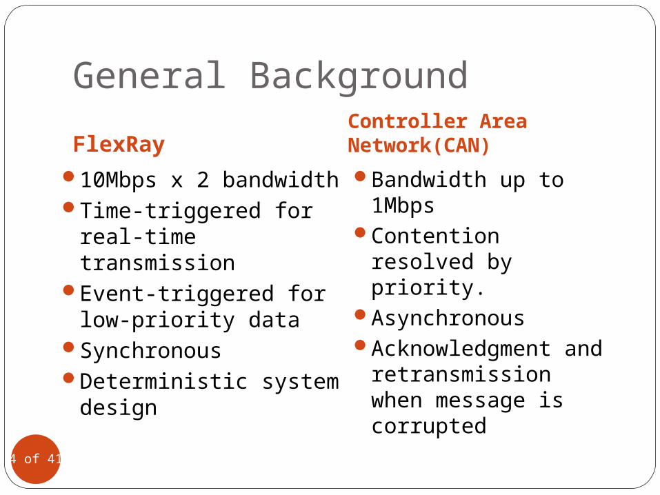
FlexRayController Area Network(CAN)
10Mbps x 2 bandwidth Time-triggered for
real-time transmissionEvent-triggered for
low-priority dataSynchronousDeterministic system
design
Bandwidth up to 1Mbps
Contention resolved by priority.
AsynchronousAcknowledgment
and retransmission when message is corrupted
4 of 41
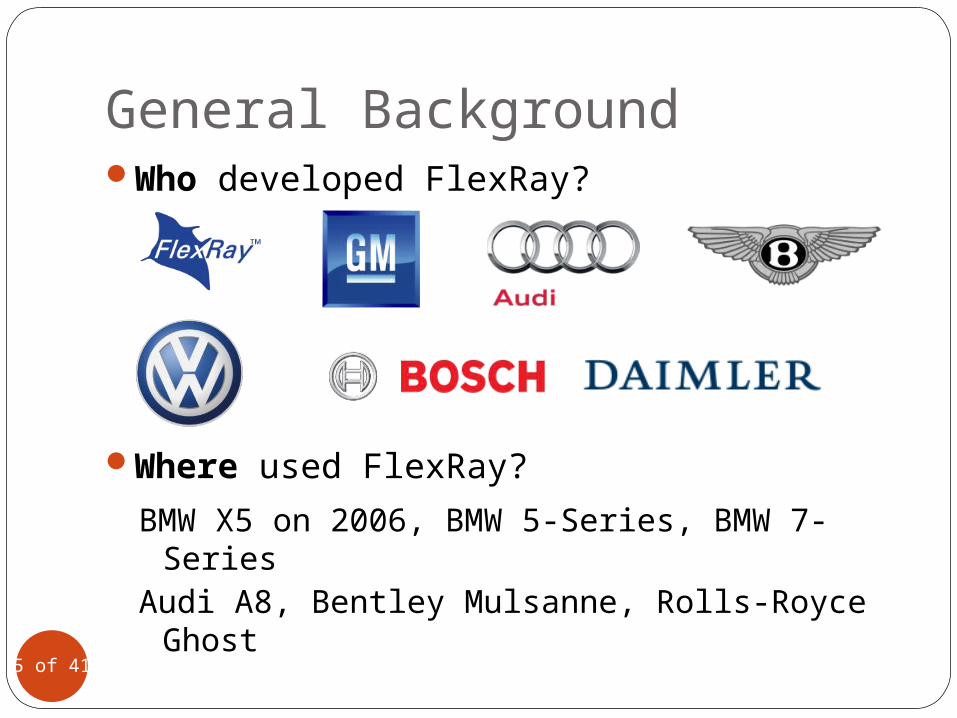
General BackgroundWho developed FlexRay?
5 of 41
Where used FlexRay?
BMW X5 on 2006, BMW 5-Series, BMW 7-SeriesAudi A8, Bentley Mulsanne, Rolls-Royce Ghost
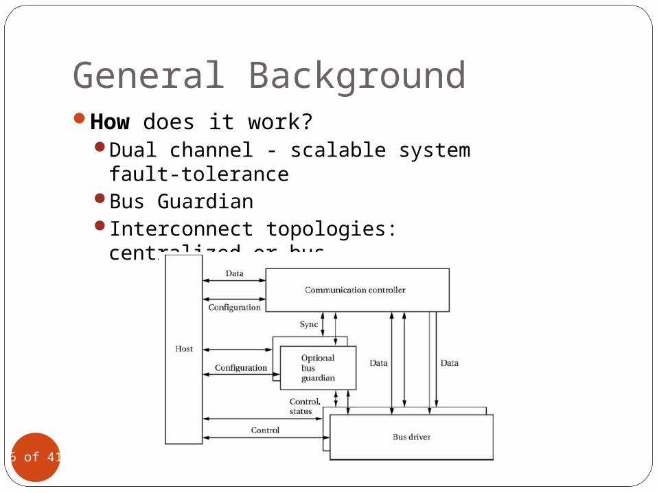
General BackgroundHow does it work?
Dual channel - scalable system fault-tolerance
Bus GuardianInterconnect topologies: centralized or
bus
6 of 41
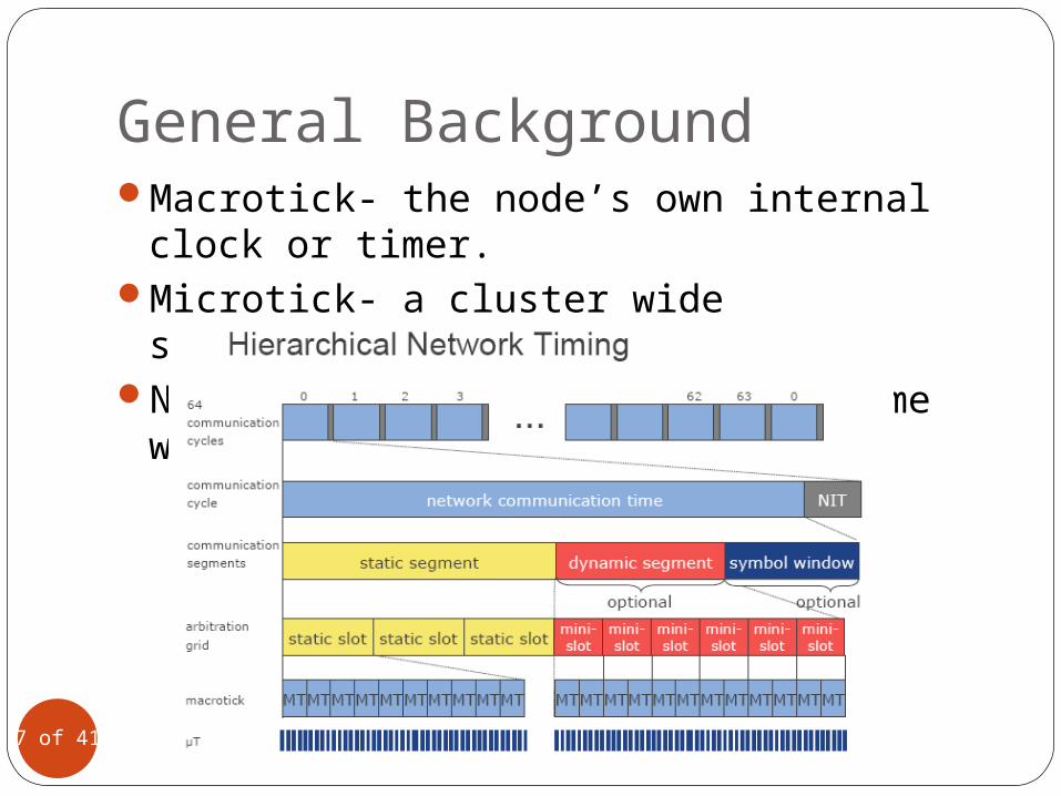
General BackgroundMacrotick- the node’s own internal clock or
timer.Microtick- a cluster wide synchronized
clock.NIT is stand for Network Idle Time which
time corrections.
7 of 41
Performance Analysis of FlexRay-based ECU Networks
Andrei Hagiescu, Unmesh D. Bordoloi, Samarjit ChakrabortyDepartment of Computer Science, National University of Singapore
Prahladavaradan Sampath, P. Vignesh V. Ganesan, S. RameshGeneral Motors R&D – India Science Laboratory, Bangalore
Design Automation Conference (DAC) 2007,San Diego, California, USA
8 of 41
MotivationIn a high-end car there are up to 70 electronic
control units (ECUs) exchanging up to 2500 signals.Commonly used protocols include CAN, local
interconnection network(LIN).Previous implementations of FlexRay using only
static segment, with the dynamic segment being unutilized.• Dynamic part of protocol is more complex.• The potential messages for dynamic segment is more
irregular.Techniques for analyzing the static segment are
known(TDMA scheme).
9 of 41
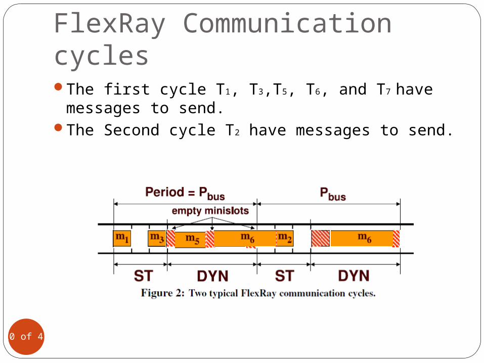
FlexRay Communication cyclesThe first cycle T1, T3,T5, T6, and T7 have
messages to send.The Second cycle T2 have messages to send.
10 of 41
Difficulties in Modeling FlexRayA message cannot straddle two
communication cycles.Once a task misses in the dynamic segment,
it will wait till the next cycle.A task can send at most one message in
each dynamic segment, where the maximum length of the message can be equal to the length of the dynamic segment.
One minislot is consumed from the available service when a task is not ready to transfer a message.
11 of 41
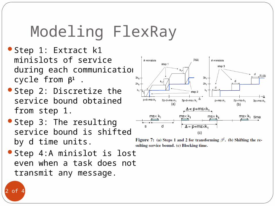
Modeling FlexRayStep 1: Extract k1 minislots
of service during each communication cycle from l .
Step 2: Discretize the service bound obtained from step 1.
Step 3: The resulting service bound is shifted by d time units.
Step 4:A minislot is lost even when a task does not transmit any message.
12 of 41
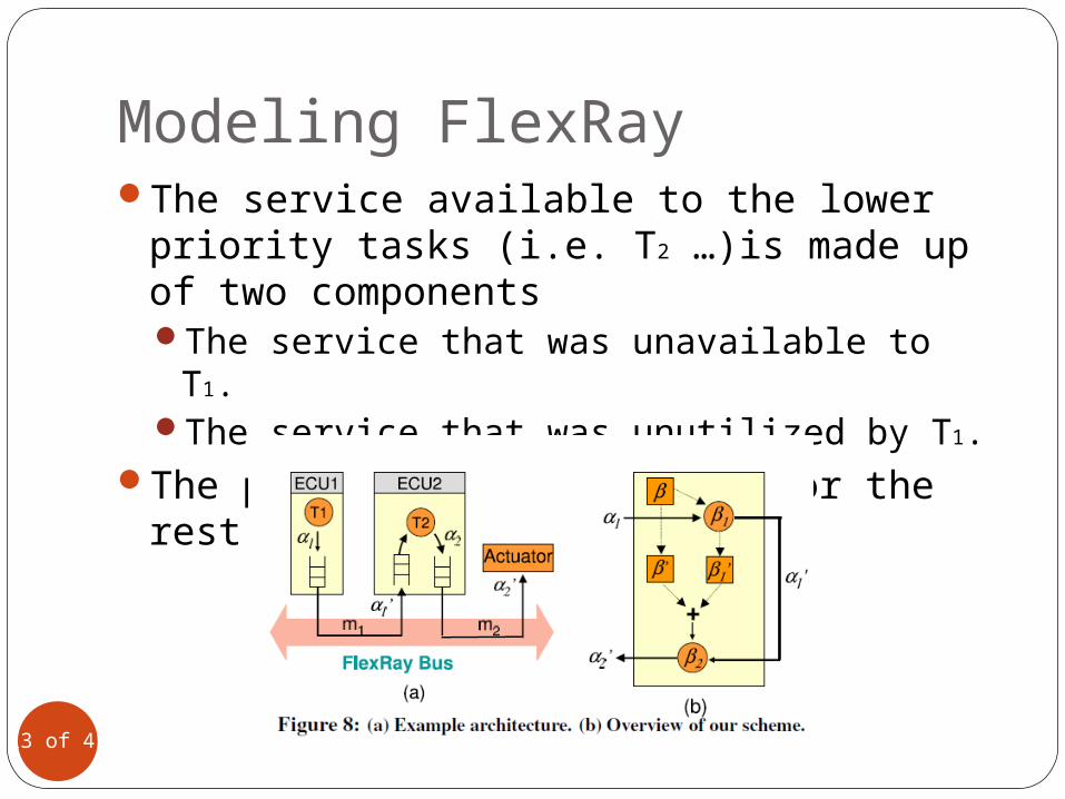
Modeling FlexRayThe service available to the lower priority
tasks (i.e. T2 …)is made up of two componentsThe service that was unavailable to T1.The service that was unutilized by T1.
The procedure is remaining for the rest tasks.
13 of 41
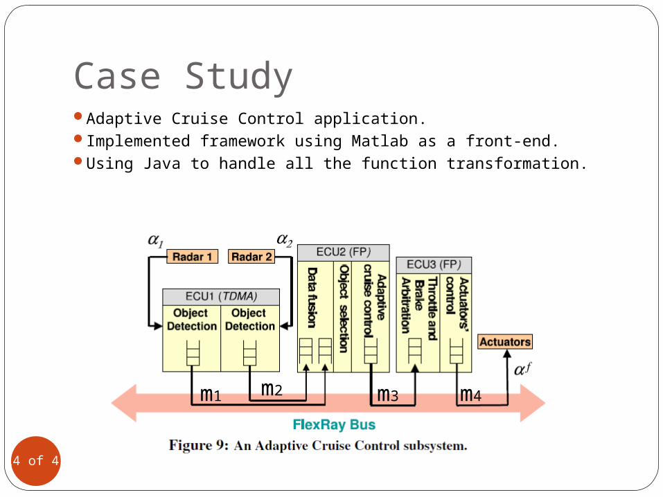
Case StudyAdaptive Cruise Control application.Implemented framework using Matlab as a front-end.Using Java to handle all the function transformation.
14 of 41
m1 m2 m3 m4
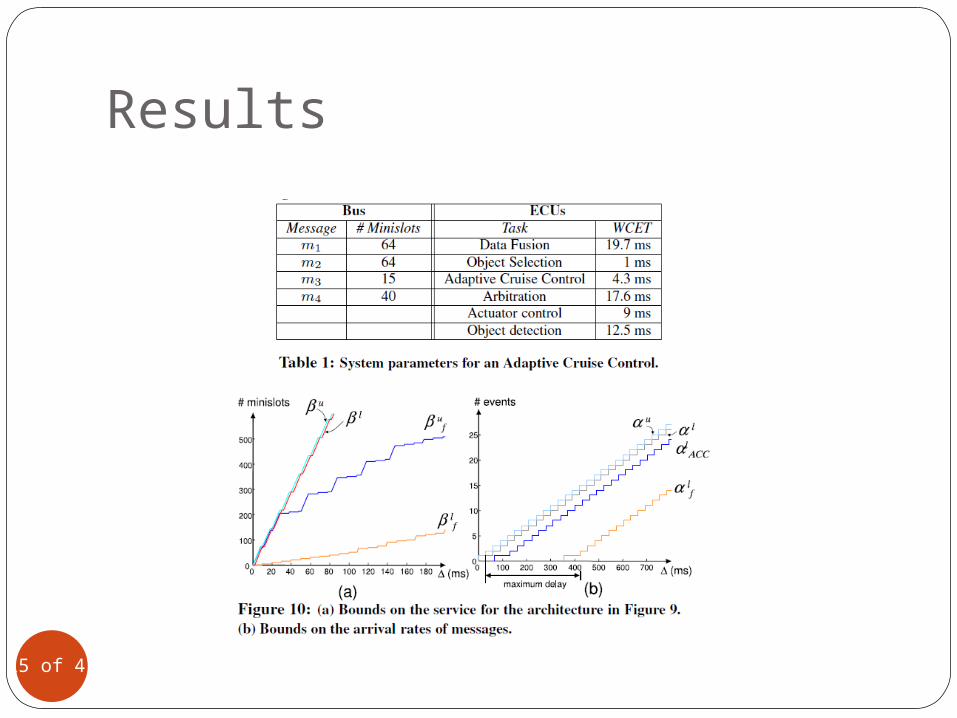
Results
15 of 41

ConclusionPresent a compositional performance
model for a network of ECUs communicating via FlexRay bus.
Formal model of the protocol governing the dynamic segment of FlexRay.
The framework can also be used for deriving the parameters of the FlexRay protocol.
Help in resource dimensioning and determining optimal scheduling policies for multitasking ECUs.
16 of 41
FlexRay Schedule Optimization of the Static SegmentMartin Lukasiewycz, Michael Glaß, and Jürgen TeichUniversity of Erlangen-Nuremberg, GermanyPaul MilbredtI/EE-81, AUDI AG, German
CODES+ISSS 2009, Grenoble, France
17 of 41
Quick ViewPresenting a Scheduling Optimization
scheme for the static segment of the FlexRay bus in compliance with the AUTOSAR specification.
What is AUTOSAR?
18 of 41

Background & Introduction
19 of 41
AUTOSARAUTomotive Open System ARchitecture
FlexRayAn Automotive Communication System
Protocol Data Units (PDUs)
Background – AUTOSARAUTomotive Open System ArchitectureOpen and Standardized automotive software
architecturePartnership for automotive E/E
(Electrics/Electronics) architecturesStandardization
Basic systems functions,Scalability to different vehicle Transferability throughout the networkMaintainability throughout the entire product life-
cycleEtc.
20 of 41
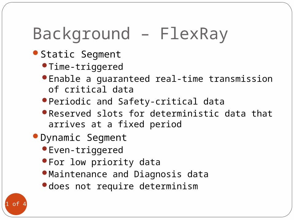
Background – FlexRayStatic Segment
Time-triggeredEnable a guaranteed real-time transmission of
critical dataPeriodic and Safety-critical dataReserved slots for deterministic data that arrives
at a fixed periodDynamic Segment
Even-triggeredFor low priority dataMaintenance and Diagnosis datadoes not require determinism
21 of 41
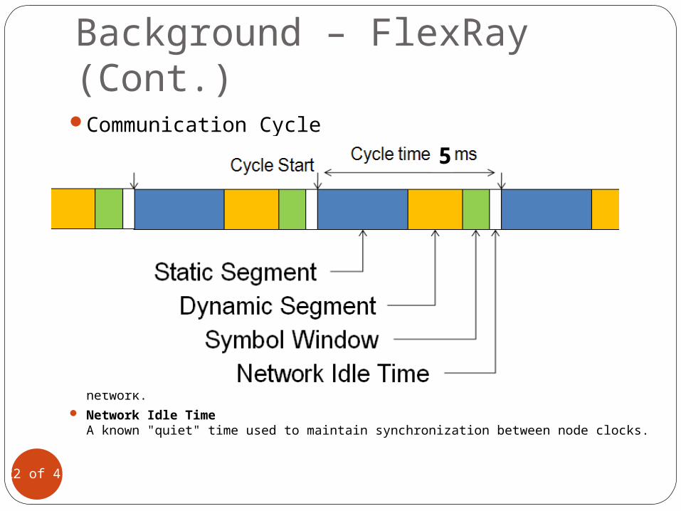
Background – FlexRay (Cont.)Communication Cycle
Symbol WindowTypically used for network maintenance and signaling for starting the network.
Network Idle TimeA known "quiet" time used to maintain synchronization between node clocks.
22 of 41
5
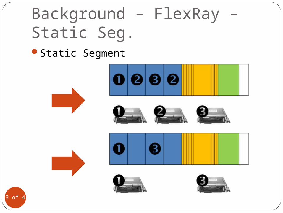
Background – FlexRay – Static Seg.Static Segment
23 of 41
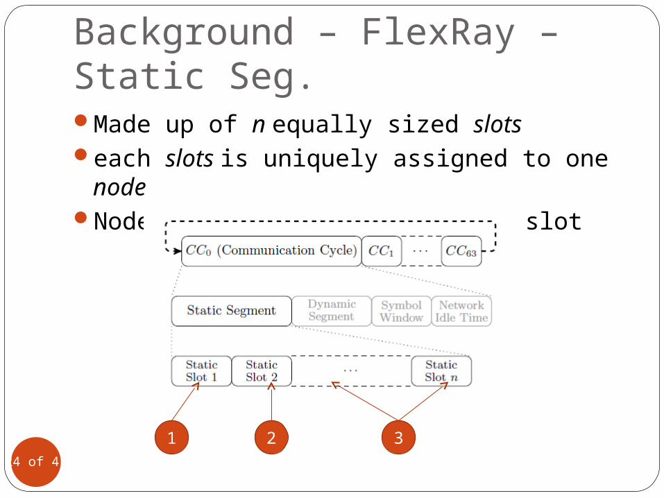
Background – FlexRay – Static Seg.Made up of n equally sized slotseach slots is uniquely assigned to one nodeNode may occupy more than one slot
24 of 41
1 2 3
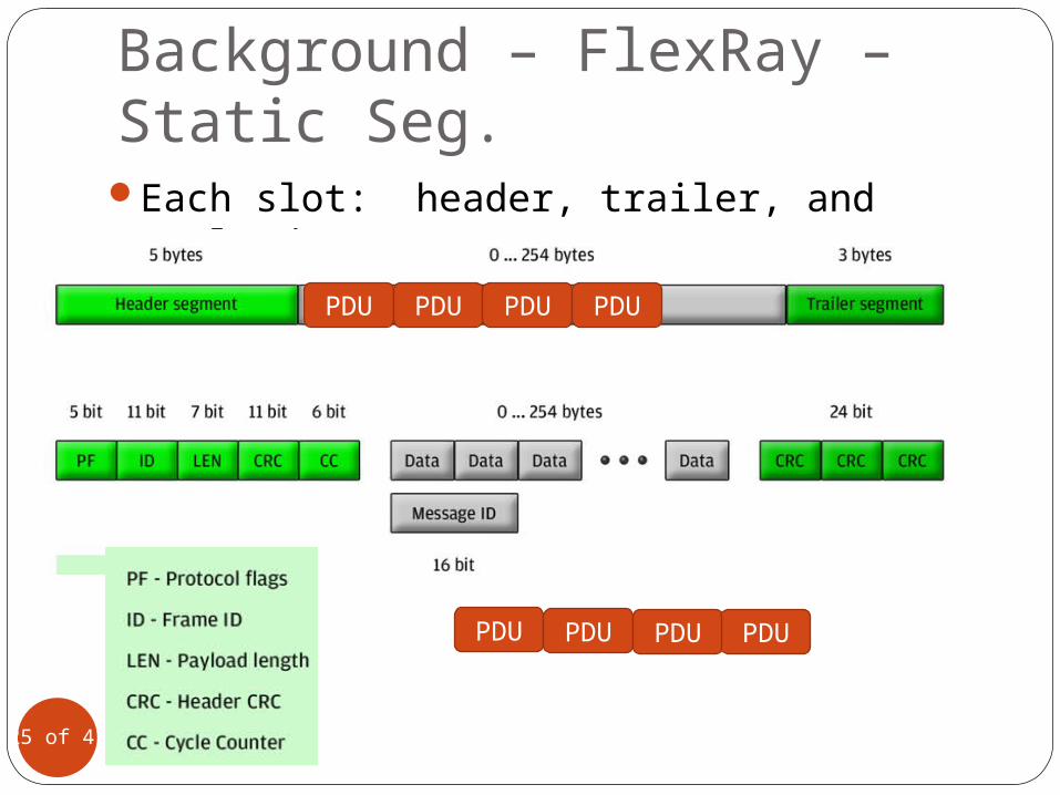
Background – FlexRay – Static Seg.Each slot: header, trailer, and payload
segment
25 of 41
PDU PDU PDU PDU
PDU PDU PDU PDU
Background – PDUs
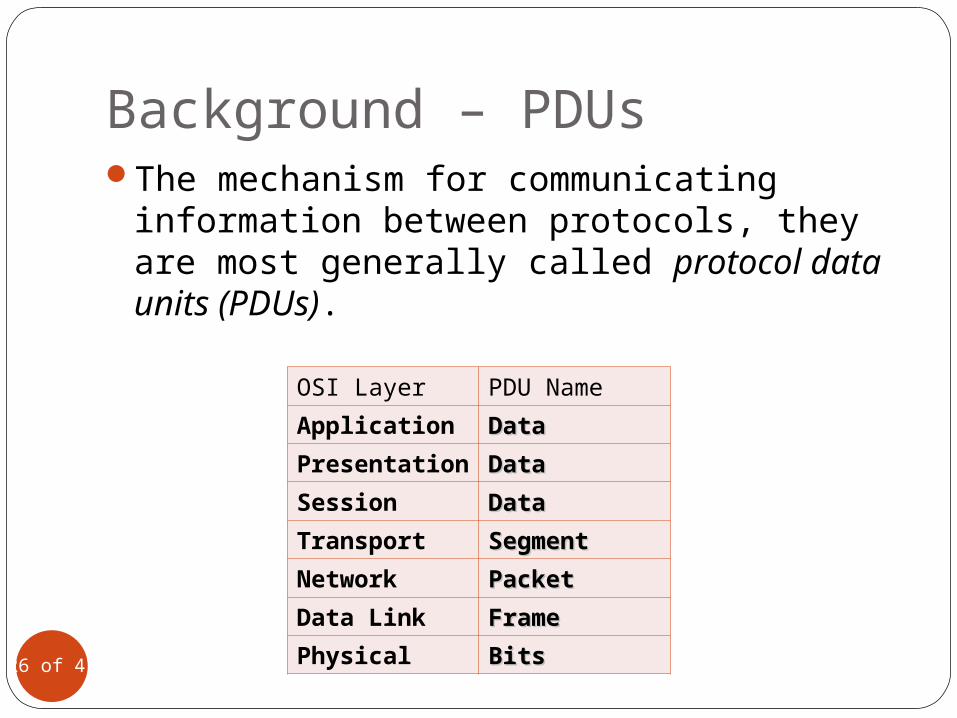
OSI Layer PDU Name
Application DataData
Presentation
DataData
Session DataData
Transport SegmentSegment
Network PacketPacket
Data Link FrameFrame
Physical BitsBits26 of 41
The mechanism for communicating information between protocols, they are most generally called protocol data units (PDUs).
Motivation
27 of 41
To minimize the number of used slots in order to maximize the utilization of the busScheduling optimization scheme for the
static segment of the FlexRay bus
Problem definition
28 of 41
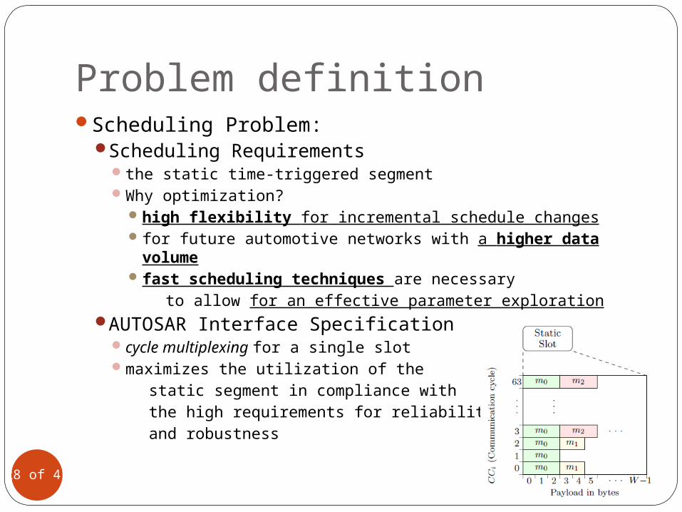
Scheduling Problem:Scheduling Requirements
the static time-triggered segmentWhy optimization?
high flexibility for incremental schedule changes for future automotive networks with a higher data
volumefast scheduling techniques are necessary to allow for an effective parameter exploration
AUTOSAR Interface Specificationcycle multiplexing for a single slotmaximizes the utilization of the static segment in compliance with the high requirements for reliability and robustness
Methodology
29 of 41
Methodology
30 of 41
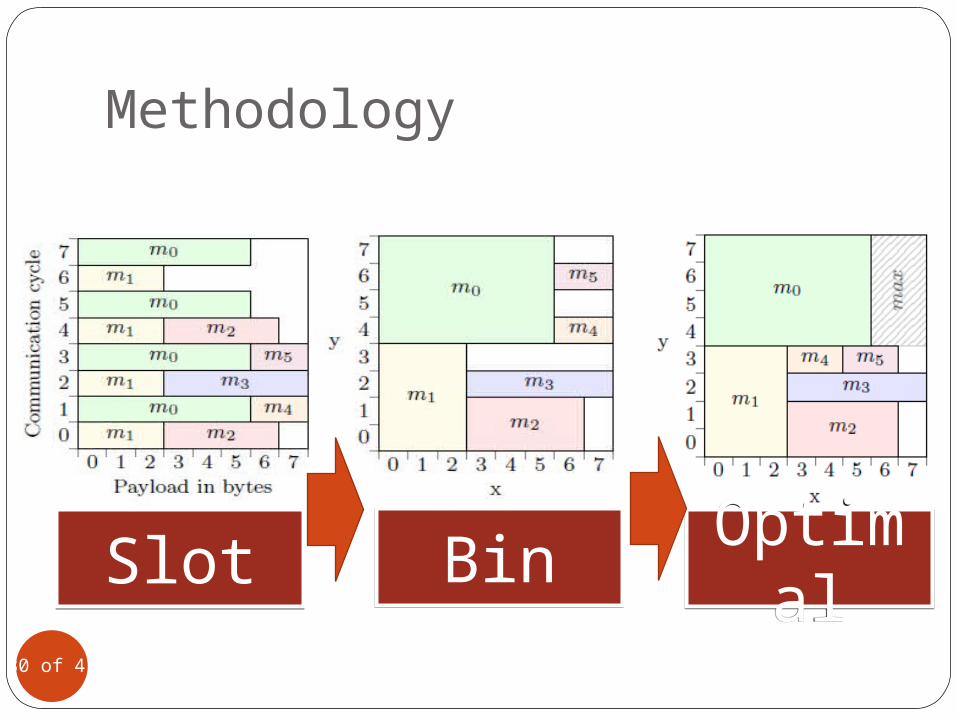
SlotSlot BinBin Optimal
Optimal
Methodology
31 of 41
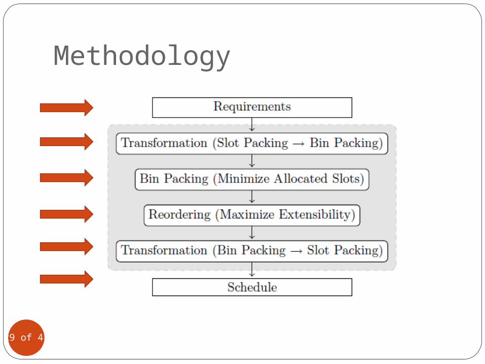
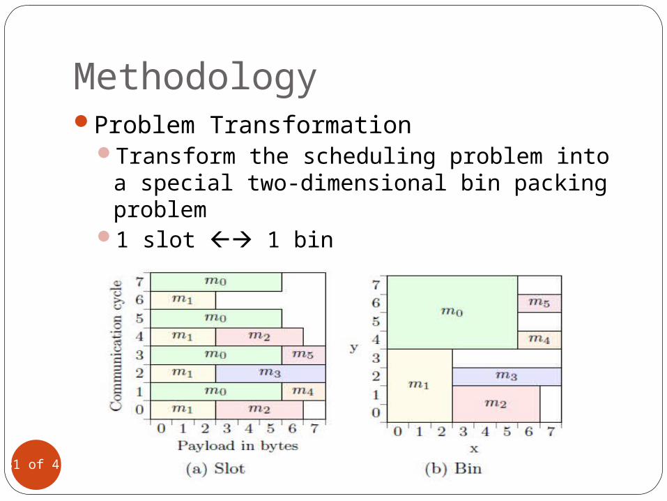
Problem TransformationTransform the scheduling problem into a
special two-dimensional bin packing problem1 slot 1 bin
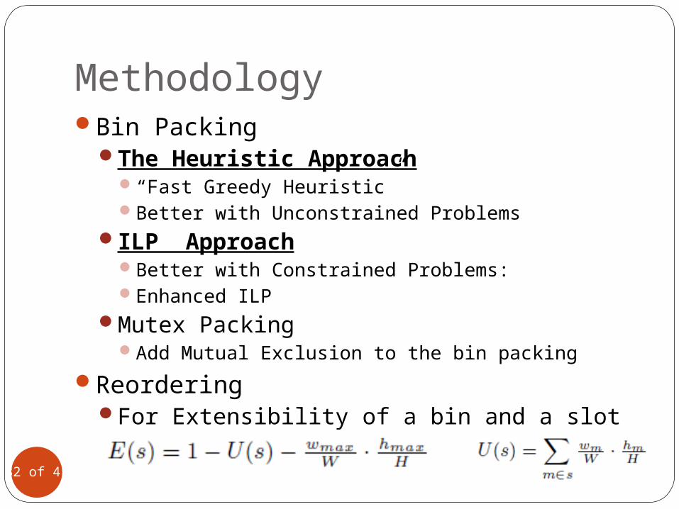
MethodologyBin Packing
The Heuristic Approach“Fast Greedy Heuristic”Better with Unconstrained Problems
ILP ApproachBetter with Constrained Problems:Enhanced ILP
Mutex PackingAdd Mutual Exclusion to the bin packing
ReorderingFor Extensibility of a bin and a slot
32 of 41

Fast Greedy Heuristic
33 of 41
“Greedy” implies: Local Optimal Global OptimalTo put “elements” into “bins”
The Order of the elements (by height and weight)Allocated new empty bin
Integer Linear Programming (ILP)
34 of 41
Placing the elements starting from the highest element to the most left void space in the bin s at the level l results in a feasible solution of the bin packing problem.
Enhanced ILPThis constraint improves the runtime of the
ILP: If the optimal solution is reached and equals the lower bound, the optimization process terminates immediately.
Experimental Results
35 of 41
Schedule OptimizationIncremental SchedulingScalability Analysis
ILP & HeuristicSlot Size ExplorationSupportive Test Case
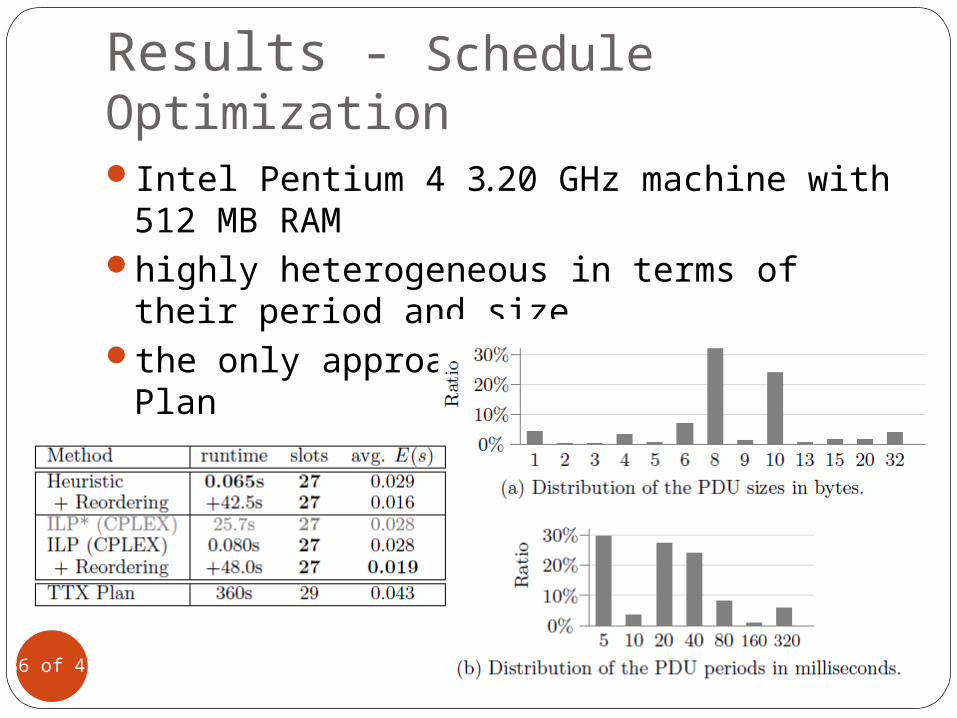
Results - Schedule OptimizationIntel Pentium 4 3.20 GHz machine with 512
MB RAMhighly heterogeneous in terms of their
period and sizethe only approach currently, TTX Plan
36 of 41
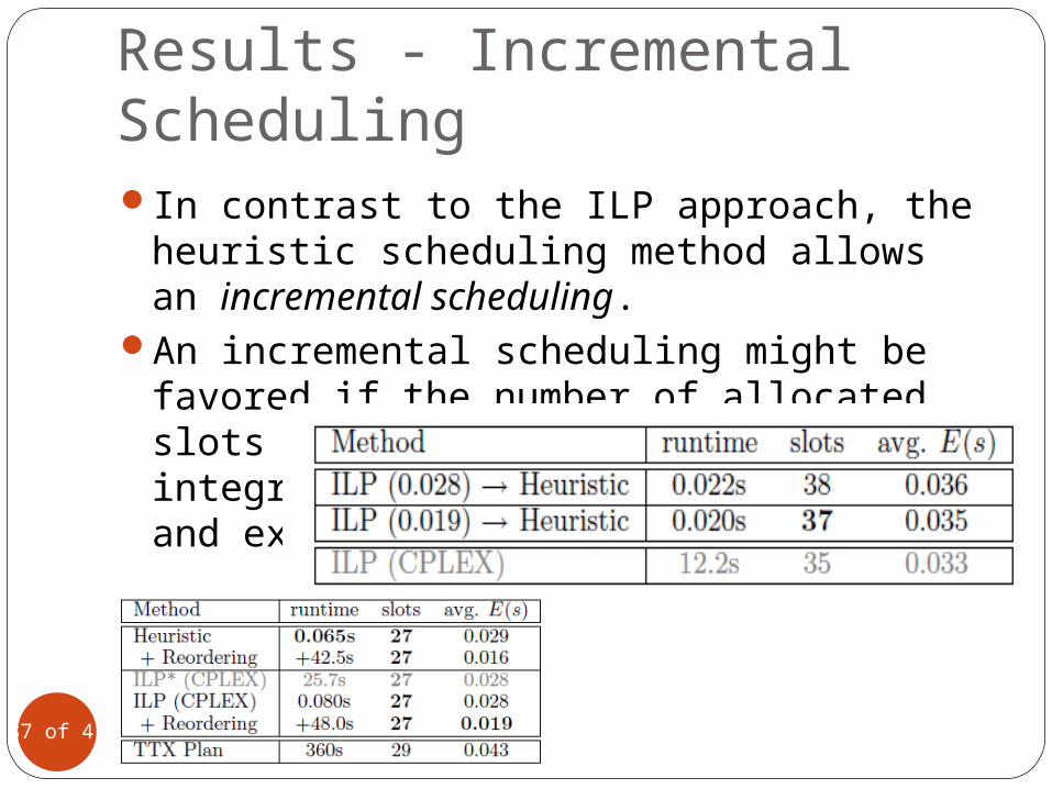
Results - Incremental SchedulingIn contrast to the ILP approach, the
heuristic scheduling method allows an incremental scheduling.
An incremental scheduling might be favored if the number of allocated slots is still not critical since integration tests are time-consuming and expensive.
37 of 41
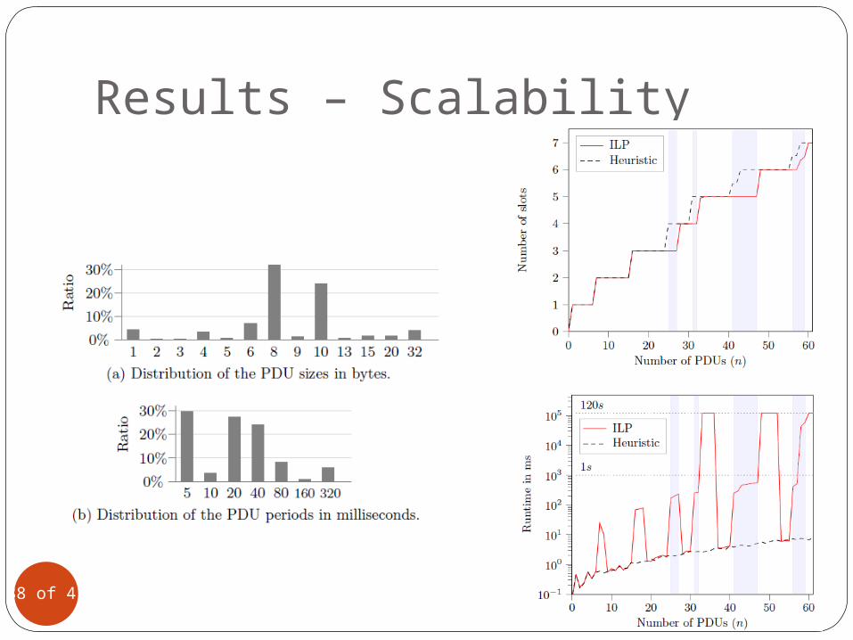
Results – Scalability
38 of 41
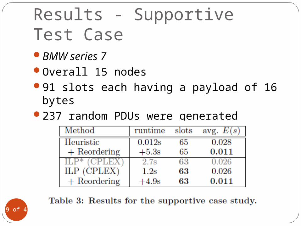
Results - Supportive Test CaseBMW series 7Overall 15 nodes91 slots each having a payload of 16 bytes237 random PDUs were generated
39 of 41
Conclusion
40 of 41
There exists no publication regarding the FlexRay bus scheduling in compliance with the industrial AUTOSAR Interface Specification.
The case study show that the heuristic and ILP approach are superior to a commercial tool in runtime and quality.
A supportive case study shows the flexibility and robustness of the proposed algorithms

Thank you!
41 of 41