chicago blower corporation - cast …the blower will run at 2470 rpm and require 1.45 bhp at 70 f...
TRANSCRIPT

CACASSTTAALLUMINUMUMINUMPPRRESSUESSURREEBBLLOWEROWER
DESIGNDESIGN 338-8-CPBCPB
CHICAGO BLOWER CORPORATION
BULLETIN CAPB-101
23902_Design 38-CPB:Design 38/CPB 4/8/08 11:42 AM Page 1

“Industrial Quality” haslong described Chicago’srugged construction andguarantees exceptionalperformance and reliability.Our fan’s most important feature isthe reliability we are able to add toyour product. If you are unsure of afan selection for a specific application,your Chicago representative will helpprovide recommendations. ChicagoBlower offices are located throughoutNorth America and around the world.
Chicago castings blend aluminum withhigh-strength alloys to create strong,corrosion-free housings and wheelsideal for adverse industrial environ-ments. Aluminum also stands up tosub-zero ambients without materialdeterioration. Since aluminum is non-magnetic and non-toxic, Chicago’spressure blowers are recommendedfor both electronic and food relatedapplications. The non-sparking proper-ties qualify Chicago’s pressure blowersfor AMCA Type B spark resistant rating.
Chicago Blower’snew series of castaluminum pressureblowers fills thediverse needsof high pressureapplications fromcombustion airto fume and dustcontrol to foodprocessing.
The same marque that has identified higher quality,extremely durable industrial fans for over 50 years is now
cast into a new series of aluminum pressure blowers.
2
23902_Design 38-CPB:Design 38/CPB 4/8/08 11:42 AM Page 2

Chicago’s WheelDesigns MeetYour PrecisePerformance
Requirement withDirect DriveReliability
Each of the eight pressure blowerhousings can be fitted with multiplewheel/inlet configurations to matchthe volume required for the application.Depending on any one size there is upto 24 combinations available.
With all these possible selections, theuser gains the efficiency and maintenance-free advantages of direct drive withthe performance versatility of belt drive.Even if performance needs shouldchange in the future, an alternate
wheel can be easily fitted to meet thenew requirement. No wasted motion.The housing and motor will usuallyremain unchanged.
Chicago’s Design 38 cast aluminumpressure blowers are offered in eightsizes from 8" to 18-1/2" in combina-tion with 64 unique wheels, all stockedfor quick assembly. They produce flowsto 5000 CFM and static pressures to20" wg. and have been performanceverified in an AMCA certified lab.
Blowersize 1000is availablewith fivewheels ofdifferingwidths anddiameters.
3
23902_Design 38-CPB:Design 38/CPB 4/8/08 11:42 AM Page 3

QualityFeaturesfrom theQualityCompany
Chicago offers two basic types ofcast aluminum wheels. Radial bladesare the most commonly used andprovide the best overall performance.They consist of either six or eightblades depending on wheel diameter.Backward curved blades haveinherently different performancecharacteristics, are somewhat quieter,but are not self-cleaning.
Wheels with tip speeds to 13,000fpm are cast of 319 aluminum whilehigher speed wheels are 356 alu-minum and heat treated. All wheelsutilize an integral straight bore huband are statically and dynamicallybalanced.
Chicago’s Design 38 pressureblowers have housings cast of319 aluminum. Their unique splithousing design with both inletand drive side cover plates providemore installation and applicationversatility.
With bolted cover plates, the
HOUSINGS
WHEELS
blower’s flow is reversable for
either clockwise or counterclock-
wise rotation. In addition, the
housings are rotatable to eight
standard discharge positions.
Bolted construction facilitates field
changeover and also simplifies
periodic cleanout.
Eight-bladedradialwheel
Six-bladedradialwheel
Back-wardcurvedwheel
4
Housingscan berotated toall eightstandarddischargepositions
23902_Design 38-CPB:Design 38/CPB 4/8/08 11:42 AM Page 4

The basic slip fit inlet is standard onChicago’s pressure blowers and iscast into the inlet coverplate.Diameters are available from 4" to10" for convenient fit of ductwork.The variety of inlet sizes helps finetune performance for direct driveblowers.
The outlet is cast into each housinghalf in 4" to 8" diameters for a slipfit duct connection.
INLETS/OUTLETS
SHAFT SEAL
RUGGED MOTOR BASE
BLOWER ARRANGEMENTS
A virgin teflon sheet is bolted to thedrive side of the housing. The seal isdesigned to reduce airstream leak-age and contamination through theblower shaft opening in the housing.
A heavy gauge steel pedestal holdsthe motor firmly in place. Theflanged and welded constructionprovides exceptional rigidly.
Motors from recognized manufac-turers are factory mounted andtested at running speed forvibration and balance.
DIRECT DRIVE• Arrangement 4, with c-face flangeand/or foot mounted motor.
• Arrangement 4V, vertical mountwith c-face flange mounted motor.Includes flanged inlet.
BELT DRIVE• Arrangement 1 includes heavysteel bearing pedestal.
• Arrangement 9 as above exceptincludes motor slide base. Motorand drives are factory mounted.
5
23902_Design 38-CPB:Design 38/CPB 4/8/08 11:42 AM Page 5

INLET/OUTLET SCREENSSpiral welded steel screen with zinc,clear chromate finish mounts over thestandard slip fit inlet or outlet. Screensare strongly recommended for installa-tions with unducted inlets or outlets.
INLET FILTEREfficient inlet filters are available aseither a disposable paper type or as acleanable, reusable wire mesh. Thecannister has a flanged base formounting to a flanged inlet.
6
FLANGED INLETS/OUTLETSCast aluminum flanges mount toeither inlet or outlet. Inlet flangeholes are on centerline. Outletflange holes straddle centerline.
HOUSING DRAINTo facilitate cleanout, a 1/2" drainwith plug is located in the lowestpoint of the housing.
VIBRATION ISOLATORSRubber-In-Shear (RIS) isolators withsteel mounting plate molded inare available for vibration sensitiveinstallations. They provide 1/4" staticdeflection.
SLIDE GATE DAMPERSDampers allow manual adjust ofair volume to suit the application.Housings are cast aluminum with agalvanized steel gate and screwlockto hold gate firmly in place. Dampersare available for inlet or outlet ineither full cutoff style mounted onthe housing, or half cutoff style thatmounts to ductwork.
OPTIONAL ACCESSORIES
Half cut-off slide gatedamper on a Series 1400blower with bottomangular up discharge.Ductwork not shown.
23902_Design 38-CPB:Design 38/CPB 4/8/08 11:42 AM Page 6
7
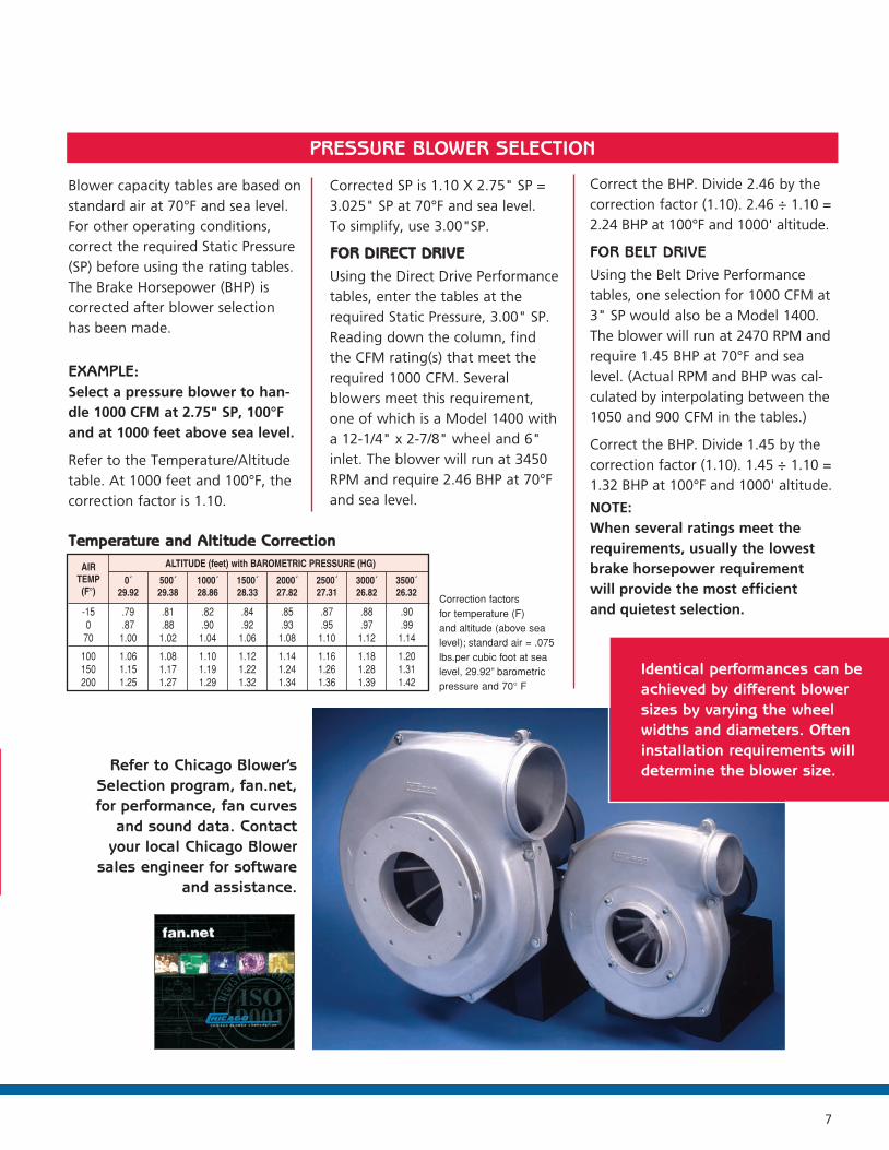
Blower capacity tables are based onstandard air at 70°F and sea level.For other operating conditions,correct the required Static Pressure(SP) before using the rating tables.The Brake Horsepower (BHP) iscorrected after blower selectionhas been made.
EXAMPLE:Select a pressure blower to han-dle 1000 CFM at 2.75" SP, 100°Fand at 1000 feet above sea level.
Refer to the Temperature/Altitudetable. At 1000 feet and 100°F, thecorrection factor is 1.10.
TTeemmppeerraattuurree aanndd AAllttiittuuddee CCoorrrreeccttiioonn
Correction factors for temperature (F) and altitude (above sealevel); standard air = .075lbs.per cubic foot at sealevel, 29.92” barometricpressure and 70° F
-150
70
100150200
.79
.871.00
1.061.151.25
.81
.881.02
1.081.171.27
.82
.901.04
1.101.191.29
.84
.921.06
1.121.221.32
.85
.931.08
1.141.241.34
.87
.951.10
1.161.261.36
.88
.971.12
1.181.281.39
AIRTEMP(F°)
0´29.92
500´29.38
1000´28.86
1500´28.33
2000´27.82
2500´27.31
3000´26.82
3500´26.32
ALTITUDE (feet) with BAROMETRIC PRESSURE (HG)
Refer to Chicago Blower’sSelection program, fan.net,for performance, fan curves
and sound data. Contactyour local Chicago Blower
sales engineer for software and assistance.
.90
.991.14
1.201.311.42
Corrected SP is 1.10 X 2.75" SP = 3.025" SP at 70°F and sea level. To simplify, use 3.00"SP.
FFOORR DDIIRREECCTT DDRRIIVVEEUsing the Direct Drive Performancetables, enter the tables at therequired Static Pressure, 3.00" SP.Reading down the column, find the CFM rating(s) that meet therequired 1000 CFM. Several blowers meet this requirement, one of which is a Model 1400 witha 12-1/4" x 2-7/8" wheel and 6"inlet. The blower will run at 3450RPM and require 2.46 BHP at 70°Fand sea level.
Correct the BHP. Divide 2.46 by thecorrection factor (1.10). 2.46 ÷ 1.10 =2.24 BHP at 100°F and 1000' altitude.
FOR BELT DRIVEUsing the Belt Drive Performancetables, one selection for 1000 CFM at3" SP would also be a Model 1400.The blower will run at 2470 RPM andrequire 1.45 BHP at 70°F and sealevel. (Actual RPM and BHP was cal-culated by interpolating between the1050 and 900 CFM in the tables.)
Correct the BHP. Divide 1.45 by thecorrection factor (1.10). 1.45 ÷ 1.10 =1.32 BHP at 100°F and 1000' altitude.
NOTE:When several ratings meet therequirements, usually the lowestbrake horsepower requirementwill provide the most efficientand quietest selection.
PRESSURE BLOWER SELECTION
Identical performances can beachieved by different blowersizes by varying the wheelwidths and diameters. Ofteninstallation requirements willdetermine the blower size.
23902_Design 38-CPB:Design 38/CPB 4/8/08 11:42 AM Page 7

CHICAGO BLOWER CORPORATIONPERFORMANCEDirect Drive
3450RPM
DESIGNDESIGN 338-8-CPBCPB
8
Performance shown is for installation type B: Free inlet, Ducted outlet. Performance ratings do not include the effects of appurtenances in the air stream.Maximum temperature 150°F.
23902_Design 38-CPB:Design 38/CPB 4/8/08 11:42 AM Page 8

CHICAGO BLOWER CORPORATION DESIGNDESIGN 338-8-CPBCPB
9
PERFORMANCEDirect Drive
3450RPM
Performance shown is for installation type B: Free inlet, Ducted outlet. Performance ratings do not include the effects of appurtenances in the air stream.Maximum temperature 150°F.
23902_Design 38-CPB:Design 38/CPB 4/8/08 11:42 AM Page 9
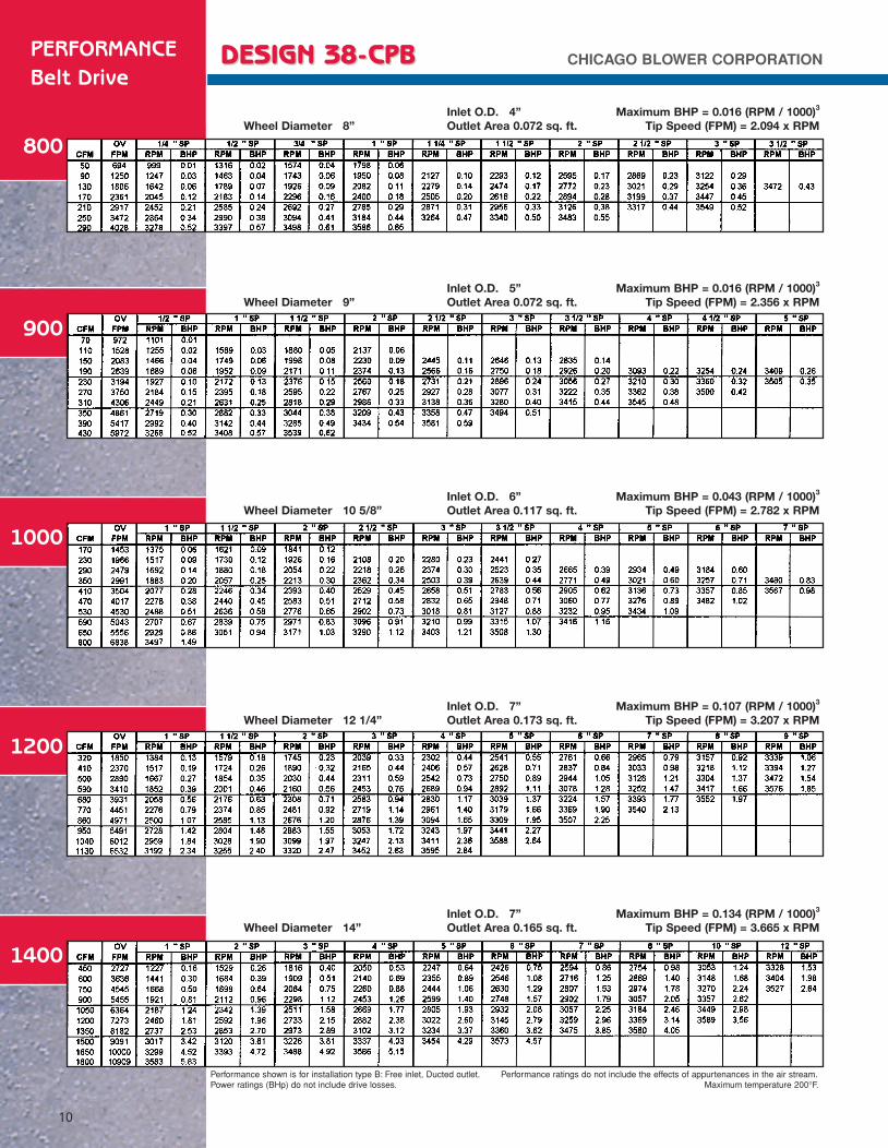
CHICAGO BLOWER CORPORATIONPERFORMANCEBelt Drive
800
DESIGNDESIGN 338-8-CPBCPB
10
Performance shown is for installation type B: Free inlet, Ducted outlet. Performance ratings do not include the effects of appurtenances in the air stream.Power ratings (BHp) do not include drive losses. Maximum temperature 200°F.
1400
1200
1000
900
Inlet O.D. 4” Maximum BHP = 0.016 (RPM / 1000)3
Wheel Diameter 8” Outlet Area 0.072 sq. ft. Tip Speed (FPM) = 2.094 x RPM
Inlet O.D. 5” Maximum BHP = 0.016 (RPM / 1000)3
Wheel Diameter 9” Outlet Area 0.072 sq. ft. Tip Speed (FPM) = 2.356 x RPM
Inlet O.D. 6” Maximum BHP = 0.043 (RPM / 1000)3
Wheel Diameter 10 5/8” Outlet Area 0.117 sq. ft. Tip Speed (FPM) = 2.782 x RPM
Inlet O.D. 7” Maximum BHP = 0.107 (RPM / 1000)3
Wheel Diameter 12 1/4” Outlet Area 0.173 sq. ft. Tip Speed (FPM) = 3.207 x RPM
Inlet O.D. 7” Maximum BHP = 0.134 (RPM / 1000)3
Wheel Diameter 14” Outlet Area 0.165 sq. ft. Tip Speed (FPM) = 3.665 x RPM
23902_Design 38-CPB:Design 38/CPB 4/8/08 11:42 AM Page 10

CHICAGO BLOWER CORPORATIONPERFORMANCE
Belt Drive
1500
DESIGNDESIGN 338-8-CPBCPB
11
Performance shown is for installation type B: Free inlet, Ducted outlet. Performance ratings do not include the effects of appurtenances in the air stream.Power ratings (BHp) do not include drive losses. Maximum temperature 200°F.
1829
1800
Inlet O.D. 5” Maximum BHP = 0.257 (RPM / 1000)3
Wheel Diameter 15.5” Outlet Area 0.307 sq. ft. Tip Speed (FPM) = 4.058 x RPM
Inlet O.D. 8” Maximum BHP = 0.333 (RPM / 1000)3
Wheel Diameter 18” Outlet Area 0.150 sq. ft. Tip Speed (FPM) = 4.712 x RPM
Inlet O.D. 10” Maximum BHP = 0.536 (RPM / 1000)3
Wheel Diameter 18.5” Outlet Area 0.287 sq. ft. Tip Speed (FPM) = 4.843 x RPM
23902_Design 38-CPB:Design 38/CPB 4/8/08 11:42 AM Page 11
800
900
1000
1200
1400
1500
1800
1829
56
56143T–145T
56143T–145T
56143T–145T182T–184T
56143T–145T182T–184T
182T–184T213T–215T254T–256T
182T–184T213T–215T254T–256T
182T–184T213T–215T254T–256T284T–286T
4
55
66
777
6, 7, 86, 7, 86, 7, 8
6, 8, 106, 8, 106, 8, 10
6, 8, 106, 8, 106, 8, 10
8, 108, 108, 108, 10
1
11
11
1-3/8
1-3/8
4
4-3/84-3/8
4-1/24-1/2
5-3/165-3/165-5/16
6-5/166-5/166-7/16
7-5/167-5/167-5/16
6-5/166-5/166-5/16
8-1/88-1/88-1/88-1/8
9-3/8
9-3/811-1/4
9-3/811-1/4
9-3/811-1/4
13-15/16
9-3/811-1/4
13-15/16
13-15/1615-9/16
19-19/32
13-15/1615-9/16
19-19/32
13-15/1615-9/16
19-19/3221-13/16
3-3/16
3-3/84-3/16
3-7/164-1/4
4-1/44-9/16
5
5-1/25-1/25-1/2
5-15/166-1/86-1/8
5-7/165-5/85-5/8
6-1/26-1/26-1/26-1/2
2-15/16
3-1/83-1/8
3-3/163-3/16
3-15/163-15/163-15/16
4-1/24-1/24-1/2
4-15/164-15/164-15/16
4-7/164-7/164-7/16
5-11/325-11/325-11/325-11/32
12-3/16
13-5/1613-13/16
13-7/1613-15/16
14-11/1615
19-3/16
20-1/420-1/420-1/4
21-1/821-5/1625-9/16
20-1/820-5/1624-9/16
24-3/3224-3/3229-3/3229-3/32
14-1/4
14-5/816-1/2
14-3/416-5/8
15-13/1617-11/16
20-3/8
16-15/1618-13/16
21-1/2
22-3/824
28-1/32
21-3/823
27-1/32
23-3/1624-13/1628-27/3231-1/16
4-3/8
5-3/45-3/4
6-3/46-3/4
7-5/167-5/167-5/16
8-1/168-1/168-1/16
8-5/88-5/88-5/8
10-1/210-1/210-1/2
9-27/329-27/329-27/329-27/32
1-1/8
1-3/161-3/16
11
7/87/87/8
1-1/81-1/81-1/8
111
15/1615/1615/16
7/87/87/87/8
4-5/8
6-1/86-1/8
6-7/86-7/8
888
8-11/168-11/168-11/16
9-13/169-13/169-13/16
10-1/210-1/210-1/2
11111111
5-5/8
7-3/87-3/8
99
9-5/89-5/89-5/8
10-1/410-1/410-1/4
11-3/811-3/811-3/8
12-11/1612-11/1612-11/16
12-7/812-7/812-7/812-7/8
6-1/2
7-7/87-7/8
9-7/169-7/16
10-1/210-1/210-1/2
11-5/1611-5/1611-5/16
12-7/812-7/812-7/8
13-3/413-3/413-3/4
14-3/3214-3/3214-3/3214-3/32
4-7/8
6-5/86-5/8
7-13/167-13/16
9-7/169-7/169-7/16
10-1/410-1/410-1/4
10-13/1610-13/1610-13/16
11-3/811-3/811-3/8
11-13/1611-13/1611-13/1611-13/16
1-1/8
1
1
4
44
55
666
666
888
666
8888
8-9/16
10-7/1611-7/8
10-7/1611-7/8
11-7/811-7/811-7/8
15-3/16
15-3/16
18181818
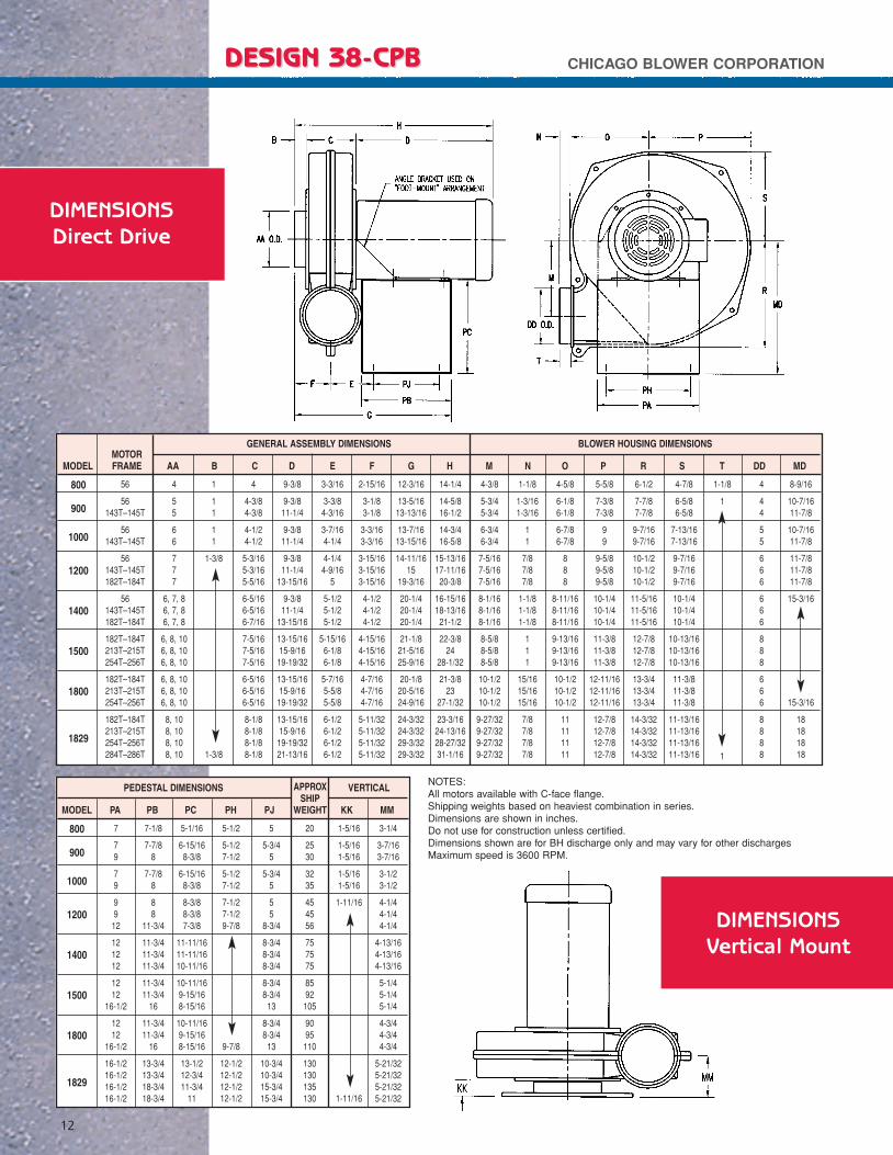
AAMOTORFRAMEMODEL B C D E F G H M N O P R S T DD MD
GENERAL ASSEMBLY DIMENSIONS BLOWER HOUSING DIMENSIONS
800
900
1000
1200
1400
1500
1800
1829
7
79
79
99
12
121212
1212
16-1/2
1212
16-1/2
16-1/216-1/216-1/216-1/2
7-1/8
7-7/88
7-7/88
88
11-3/4
11-3/411-3/411-3/4
11-3/411-3/4
16
11-3/411-3/4
16
13-3/413-3/418-3/418-3/4
5-1/16
6-15/168-3/8
6-15/168-3/8
8-3/88-3/87-3/8
11-11/1611-11/1610-11/16
10-11/169-15/168-15/16
10-11/169-15/168-15/16
13-1/212-3/411-3/4
11
5-1/2
5-1/27-1/2
5-1/27-1/2
7-1/27-1/29-7/8
9-7/8
12-1/212-1/212-1/212-1/2
5
5-3/45
5-3/45
55
8-3/4
8-3/48-3/48-3/4
8-3/48-3/4
13
8-3/48-3/4
13
10-3/410-3/415-3/415-3/4
20
2530
3235
454556
757575
8592
105
9095
110
130130135130
1-5/16
1-5/161-5/16
1-5/161-5/16
1-11/16
1-11/16
3-1/4
3-7/163-7/16
3-1/23-1/2
4-1/44-1/44-1/4
4-13/164-13/164-13/16
5-1/45-1/45-1/4
4-3/44-3/44-3/4
5-21/325-21/325-21/325-21/32
MODEL PA PB PC PH PJ
APPROXSHIP
WEIGHT KK MM
PEDESTAL DIMENSIONS VERTICAL
DIMENSIONS Vertical Mount
CHICAGO BLOWER CORPORATIONDESIGNDESIGN 338-8-CPBCPB
12
DIMENSIONS Direct Drive
NOTES:All motors available with C-face flange.Shipping weights based on heaviest combination in series.Dimensions are shown in inches. Do not use for construction unless certified.Dimensions shown are for BH discharge only and may vary for other dischargesMaximum speed is 3600 RPM.
23902_Design 38-CPB:Design 38/CPB 4/8/08 11:42 AM Page 12

800
900
1000
1200
1400
1500
1800
1829
56
56
56143T–145T
56143T–145T182T–184T
56143T–145T182T–184T213T–215T
182T–184T213T–215T254T–256T
182T–184T213T–215T254T–256T
182T–184T213T–215T254T–256T
4
5
66
777
6, 7, 86, 7, 86, 7, 86, 7, 8
6, 8, 106, 8, 106, 8, 10
6, 8, 106, 8, 106, 8, 10
8, 108, 108, 10
1
1
11
1-3/8
1-3/8
3-15/16
4-5/16
4-7/164-7/16
5-1/45-1/45-1/4
6-3/86-3/86-3/86-3/8
7-1/47-1/47-1/4
6-1/46-1/46-1/4
8-1/168-1/168-1/16
16-1/8
16-1/8
16-1/816-1/4
16-1/1616-1/1616-1/16
16161919
1919
25-1/2
19-3/1619-3/16
25-11/16
19-5/3219-5/32
25-21/32
5-3/8
5-13/16
5-7/85-7/8
6-1/46-1/46-1/4
6-3/46-3/46-3/46-3/4
7-3/87-3/87-3/8
6-7/86-7/86-7/8
7-3/47-3/47-3/4
2-15/16
3-1/8
3-3/163-3/16
3-15/163-15/163-15/16
4-1/24-1/24-1/24-1/2
4-15/164-15/164-15/16
4-7/164-7/164-7/16
5-11/325-11/325-11/32
21-1/16
21-7/16
21-9/1621-9/16
22-11/1622-11/1625-11/16
23-3/423-3/426-3/426-3/4
27-5/827-5/834-1/8
26-13/1626-13/1633-5/16
28-19/3228-19/3235-3/32
23-3/16
23-9/16
23-11/1624-1/16
24-13/1625-3/16
28-11/16
25-7/826-1/429-3/430-3/8
30-5/831-1/438-3/8
29-13/1630-7/1637-9/16
31-19/3231-7/32
39-11/32
2-1/8
2-1/8
2-1/82-1/8
2-1/82-1/2
3
2-1/82-1/2
33-5/8
33-5/84-1/4
33-5/84-1/4
33-5/84-1/4
15
15
1515
151519
19191919
191926
191926
191926
AAMOTORFRAMEMODEL B C D E F G H I ML
GENERAL ASSEMBLY DIMENSIONS
800
900
1000
1200
1400
1500
1800
1829
56
56
56143T–145T
56143T–145T182T–184T
56143T–145T182T–184T213T–215T
182T–184T213T–215T254T–256T
182T–184T213T–215T254T–256T
182T–184T213T–215T254T–256T
4-3/8
5-3/4
6-3/46-3/4
7-5/167-5/167-5/16
8-1/168-1/168-1/168-1/16
8-5/88-5/88-5/8
10-1/210-1/210-1/2
9-27/329-27/329-27/32
1-1/8
1-3/16
11
7/87/87/8
1-1/81-1/81-1/81-1/8
111
15/1615/1615/16
7/87/87/8
4-5/8
6-1/8
6-1/86-7/8
888
8-11/168-11/168-11/168-11/16
9-13/169-13/169-13/16
10-1/210-1/210-1/2
111111
5-5/8
7-3/8
99
9-5/89-5/89-5/8
10-1/410-1/410-1/410-1/4
11-3/811-3/811-3/8
12-11/1612-11/1612-11/16
12-7/812-7/812-7/8
6-1/2
7-7/8
9-7/169-7/16
10-1/210-1/210-1/2
11-5/1611-5/1611-5/1611-5/16
12-7/812-7/812-7/8
13-3/413-3/413-3/4
14-3/3214-3/3214-3/32
4-7/8
6-5/8
7-13/167-13/16
9-7/169-7/169-7/16
10-1/410-1/410-1/410-1/4
10-13/1610-13/1610-13/16
11-3/811-3/811-3/8
11-13/1611-13/1611-13/16
1-1/8
1
1
4
4
55
666
6666
888
666
888
14
14
1414
141418
18181818
181823
181823
181823
11-1/2
11-1/2
11-1/211-1/2
11-7/811-7/814-1/2
11-7/811-7/814-1/215-1/4
14-9/1615-1/4
17-15/16
14-15/1615-5/8
18-15/16
14-15/1615-5/8
18-5/16
1-1/16
1-1/16
1-1/161-1/16
1-1/321-1/321-7/32
1-1/321-1/321-1/8
1-7/32
1-7/321-1/4
1-7/16
1-1/161-1/4
1-7/16
1-1/161-3/161-7/16
13-3/8
13-3/8
13-3/813-3/8
13-3/813-3/8
18
18181818
1818
19-1/4
1818
19-1/4
1818
19-1/4
15
15
1515
151518
18181818
1818
24-1/2
1818
24-1/2
1818
24-1/2
11-3/8
11-3/8
11-3/811-3/8
11-3/811-3/8
16
16161616
1616
17-1/4
1616
17-1/4
1616
17-1/4
10
10
1010
101013
13131313
1313
19-1/2
1313
19-1/2
1313
19-1/2
65
70
7580
9595
125
105105135135
155155200
165165215
175180225
MMOTORFRAMEMODEL N O P R S T DD BD CD +/– CD PA PB PH PJ
APPROX.SHIP
WEIGHT
GENERAL ASSEMBLY DIMENSIONS PEDESTAL DIMENSIONS
NOTES:
Shipping weights (lessmotor)based on heaviest combination in series.
Unit shown is right sidemount. Left side mountavailable.
(ML) Max. motor length.
Dimensions are shownin inches.
Do not use for construction unless certified.
Dimensions shown arefor BH discharge onlyand may vary for otherdischarges.
Maximum speed is3600 RPM.
DIMENSIONS Vertical Mount
CHICAGO BLOWER CORPORATION DESIGNDESIGN 338-8-CPBCPB
13
DIMENSIONS Belt Drive
23902_Design 38-CPB:Design 38/CPB 4/8/08 11:42 AM Page 13

456
78
10
4-1/165-1/166-1/16
7-1/168-1/16
10-1/16
91111
1113-1/2
16
7-1/28-1/29-1/2
9-1/211-3/414-1/4
3-11/164-9/165-1/2
6-7/167-1/2
9-11/16
4-9/165-9/166-9/16
7-5/88-5/8
10-9/16
444
888
15/1615/161-1/16
15/1611
AA or DD FA FB* FC* FD FE
NO. ofFG
HOLES FH
NOTES:* Meets ANSI-125 lb.flange dimensions.FA fits over the Inlet(AA) or Discharge (DD)
456
78
10
3-7/84-15/165-15/16
6-7/87-15/169-15/16
6-3/48-5/8
10-1/4
11-1/412-5/817-7/8
2-1/42-3/43-1/4
3-3/44-1/45-3/4
3-1/25
5-1/4
5-3/46-3/47-5/8
6-3/49-1/4
10
11-3/41417
56
7-1/4
89-5/8
11-3/4
4-1/85-3/86-1/2
7-1/48-5/8
10-1/2
1-1/81-1/81-1/2
1-1/41-3/42-1/8
3-1/44-5/85-3/8
6-3/47-1/29-1/2
5/163/83/8
3/87-1/69/16
11-3/42-1/4
2-1/23-3/47-3/4
SIZE A B C D E F G H K L WGT.
CHICAGO BLOWER CORPORATIONDESIGNDESIGN 338-8-CPBCPB
14
DIMENSIONS Full Cut-Off Damper
DIMENSIONS Inlet/Outlet Flange
Dimensions are shown in inches. Do not use for construction unless certified.
Dimensions are shown in inches. Do not use for construction unless certified.
23902_Design 38-CPB:Design 38/CPB 4/8/08 11:42 AM Page 14

ENGINEERINGSPECIFICATIONS
Centrifugal CPB Fans
GENERAL:Provide a high performance, low maintenance, centrifugal fan with radialwheel. Fan shall be air performance tested based on tests and proceduresin accordance with AMCA 211. Fans must be manufactured and assembledin the U.S.A. Acceptable vendors: Chicago Blower Corporation
PERFORMANCE:Performance shall include steep pressure and overloading horsepower char-acteristics. Mechanical efficiency shall be no less than 60%. System staticpressure changes of 30% shall result in no more than 10% CFM reduction.
HOUSING:Housing shall be cast with 319 cast aluminum, having a 3/16" minimumwall thickness. Housing should consist of two halves which are bolted andsealed. Inlets and outlets shall be round of nominal diameters for slip fit ofductwork, flexible connector, or hose. Housings include a Teflon shaft seal.All housing sizes shall be reversible for clockwise or counterclockwiseand capable of being rotated to all eight standard discharge positions.
WHEEL:Wheels with tip speeds to 13,000 feet per minute shall be 319 cast aluminum. Wheels with tip speeds over 13,000 feet per minute shall be 356 cast aluminum with T6 heat treatment. All wheels shall have an inte-gral straight bore hub keyed with set screws for mounting. Wheels to bestatically and dynamically balanced to G 6.3 standards in accordance withISO 1940 and ANSI S2.19 specifications. The addition of weights is notallowed, thus balancing shall be accomplished by material removal only.
MOUNTING:Motorbase-Fan shall be mounted with heavy gauge steel pedestal.
FACTORY MOUNTED MOTORS:Motors to be factory mounted. Unit to be tested at running speed forvibration and balance. Filtered vibration readings, taken at bearings, not toexceed .22 inches per second.
ACCESSORIES:• Flanged Inlet/Outlet – 319 Cast Aluminum with Punched Holes
• 1/2" NPT Housing Drain with Plug
• Inlet/Outlet Screen
• RIS Isolators
• Inlet Filter
• Slide Gate Damper
• Belt Guard
• Shaft and Bearing Guard
15
23902_Design 38-CPB:Design 38/CPB 4/8/08 11:42 AM Page 15
