chennai institute of technology - · pdf filechennai institute of technology ... laboratory...
TRANSCRIPT

CHENNAI INSTITUTE OF TECHNOLOGY
Kundrathur to Sriperumbudur Highway, Kundrathur,Nandhambakkam Post, Pudupedu,
Chennai– 600 069.
DEPARTMENTOF ELECTRONICS AND COMMUNICATION
ENGINEERING
LABORATORY MANUAL
EE 6461Electrical Engineering and Control System Laboratory

2
LIST OF EXPERIMENTS
1. Open circuit and load characteristics of separately excited and self excited
D.C.Generator.
2. Load test on DC shunt motor.
3. Swinburne’s test and speed control of DC shunt motor.
4. Load test on single phase transformer and open circuit and short circuit test on single phase
transformer
5. Regulation of three phase alternator by EMF and MMF methods.
6. Load test on three phase induction motor.
7. No load and blocked rotor tests on three phase induction motor (Determination of equivalent
circuit parameters and predetermination of performance characteristics at various loads)
8. Study of D.C. motor and induction motor starters.
9. Digital simulation of linear systems.
10. Stability analysis of linear system using MATLAB.
11. Study the effect of P, PI, PID controllers using MATLAB.
12. Design of lead and lag compensator.
13. Transfer function of separately excited D.C. generator.
14. Transfer function of armature and field controlled DC motor

3
Ex. No: 1A
Date:
OCC AND LOAD CHARACTERISTICS OF SEPARATELY EXCITED D.C GENERATOR
Aim:
To conduct no load and load test on separately excited generators and to obtain the
characteristics
Exercise
1. Obtain the open circuit characteristics (OCC) of a separately excited D.C generator and
determine critical resistance.
2. Draw the external and internal characteristics of a separately excited D.C generator and compute
full load regulation.
Apparatus Required:
Sl.no Name of the component Specification Quantity
Name plate details:
Motor Generator
Fuse rating calculation for field and armature:
No load test
10 % of rated current (full load current)
Load test
125 % of rated current (full load current)
Precautions
1. Motor side field rheostat should be kept at minimum resistance position.
2. Generator side field rheostat should be kept at maximum resistance position.
3. Starter should be in off position before switching on the supply.
4. The DPST switch must be kept open.
4
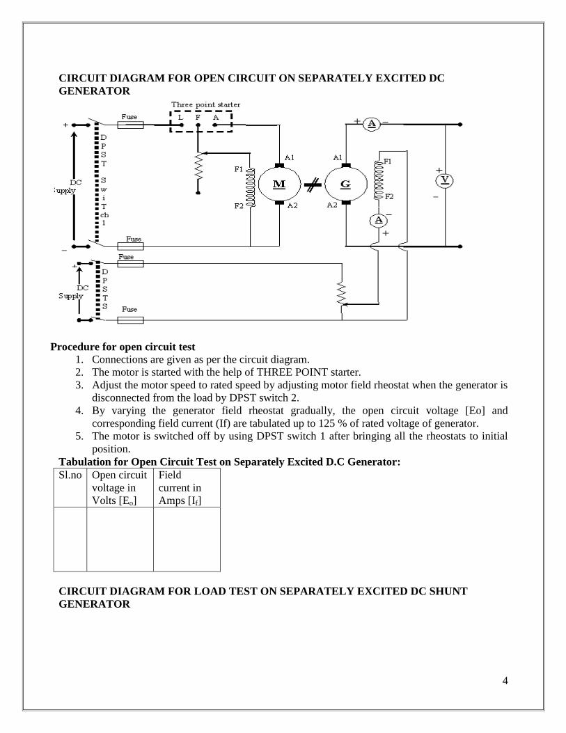
CIRCUIT DIAGRAM FOR OPEN CIRCUIT ON SEPARATELY EXCITED DC
GENERATOR
Procedure for open circuit test
1. Connections are given as per the circuit diagram.
2. The motor is started with the help of THREE POINT starter.
3. Adjust the motor speed to rated speed by adjusting motor field rheostat when the generator is
disconnected from the load by DPST switch 2.
4. By varying the generator field rheostat gradually, the open circuit voltage [Eo] and
corresponding field current (If) are tabulated up to 125 % of rated voltage of generator.
5. The motor is switched off by using DPST switch 1 after bringing all the rheostats to initial
position.
Tabulation for Open Circuit Test on Separately Excited D.C Generator:
Sl.no Open circuit
voltage in
Volts [Eo]
Field
current in
Amps [If]
CIRCUIT DIAGRAM FOR LOAD TEST ON SEPARATELY EXCITED DC SHUNT
GENERATOR

5
Procedure for Load test:
1. Connections are given as per the circuit diagram
2. The prime mover is started with the help of three point starter and it is made to run at rated speed
when the generator is disconnected from the load by DPST switch 2.
3. By varying the generator field rheostat gradually, the rated voltage [Eg] is obtained.
4. The ammeter and voltmeter readings are observed at no load condition.
5. The ammeter and voltmeter readings are observed for different loads up to the rated current by
closing the DPST switch 2.
6. After tabulating all the readings the load is brought to its initial position.
7. The motor is switched off by using DPST switch 1 after bringing all the rheostats to initial
position.
Tabulation for Load Test:
Sl.no
Armature
current
[Ia] in
Amps
Load
voltage
[VL] in
Volts
Load
current
[IL] in
Amps
Armature
drop Ia Ra
In volts
Generated
emf
[Eg =
VL+IaRa]
In volts

6
Circuit diagram for find the generator armature resistance [Ra]
Procedure for find armature resistance Ra:
1. Connections arte given as per circuit diagram
2. Check loading rheostat must be at maximum resistance position.
3. Close the DPST switch and vary the loading rheostat for various values in steps and noted
the corresponding voltmeter and ammeter reading.
4. Open the DPST switch after loading rheostat begins its initial position.
Tabulation for Finding Armature Resistance:
Sl.no Armature voltage
Va
Armature current
I Ra = Va/ Ia
Model graph
Open circuit characteristics Internal (Eg Vs Ia) and External (VL Vs IL)
characteristics
Result:
If
Field current
[If] in amps
Open
cir
cuit
volt
age
in
Volt
s [E
o]
Eo Vs If
Load current [IL] in amps
Armature current [Ia] in amps
Load
volt
age
in V
olt
s [V
L]
Gen
erat
ed e
mf
in V
olt
s [E
g]
Eg Vs Ia
VL Vs IL

7
Ex. No: 1B
Date:
OCC AND LOAD CHARACTERISTICS OF SELF EXCITED D.C SHUNT GENERATOR
Aim:
To conduct no load and load test on self excited generators and obtain the characteristics
Exercise
1. Obtain the open circuit characteristics (OCC) of a self excited D.C generator
and determine critical resistance.
2. Draw the external and internal characteristics of a self excited D.C generator
and compute full load regulation.
Apparatus Required:
Sl.no Name of the component Specification Quantity
Name plate details:
Motor Generator
Fuse rating calculation for field and armature:
No load test
10 % of rated current (full load current)
Load test
125 % of rated current (full load current)
Formula used:
Generated voltage Eg = VL + Ia Ra
Precautions 1. Motor side field rheostat should be kept at minimum resistance position.
2. Generator side field rheostat should be kept at maximum resistance position.
3. Starter should be in off position before switching on the supply.
4. The DPST switch must be kept open.

8
CIRCUIT DIAGRAM FOR OPEN CIRCUIT TEST ON SELF EXCITED DC SHUNT
GENERATOR
Procedure for open circuit test
1. Connections are given as per the circuit diagram.
2. The motor is started with the help of THREE POINT starter.
3. Adjust the motor speed to rated speed by adjusting motor field rheostat when the generator is
disconnected from the load by DPST switch 2.
4. By varying the generator field rheostat gradually, the open circuit voltage [Eo] and
corresponding field current (If) are tabulated up to 125 % of rated voltage of generator.
5. The motor is switched off by using DPST switch 1 after bringing all the rheostats to initial
position.
CIRCUIT DIAGRAM FOR LOAD TEST ON SELF EXCITED DC SHUNT GENERATOR
Procedure for Load test:
1. Connections are given as per the circuit diagram
2 The prime mover is started with the help of three point starter and it is made to run at rated
speed when the generator is disconnected from the load by DPST switch 2.
3. By varying the generator field rheostat gradually, the rated voltage [Eg] is obtained.
4. The ammeter and voltmeter readings are observed at no load condition.
5. The ammeter and voltmeter readings are observed for different loads up to the rated
current by closing the DPST switch 2.

9
6. After tabulating all the readings the load is brought to its initial position.
7. The motor is switched off by using DPST switch 1 after bringing all the rheostats to
initial position.
Tabulation for Open Circuit Test on Separately Excited D.C Shunt Generator:
Sl.no Open circuit
voltage in
Volts [Eo]
Field
current in
Amps [If]
Tabulation for Load Test:
Sl.no
Armature
current
[Ia] in
Amps
Load
voltage
[VL] in
Volts
Load
current
[IL] in
Amps
Armature
drop Ia
Ra
In volts
Generated
emf [Eg
=
VL+IaRa]
In volts
Circuit diagram for find the generator armature resistance [Ra]
Procedure for find armature resistance Ra:
1. Connections are given as per circuit diagram
2. Check loading rheostat must be at maximum resistance position.
3. Close the DPST switch and vary the loading rheostat for various values in steps and noted
the corresponding voltmeter and ammeter reading.
4. Open the DPST switch after loading rheostat begins its initial position.

10
Tabulation for Finding Armature Resistance:
Sl.no Armature voltage
Va
Armature current
I Ra = Va/ Ia
Model graph
Open circuit characteristics
Internal (Eg Vs Ia) and External (VL Vs IL) characteristics
Result:
Load current [IL] in amps
Armature current [Ia] in amps
Load
volt
age
in V
olt
s [V
L]
Gen
erat
ed e
mf
in V
olt
s [E
g]
Eg Vs Ia
VL Vs IL
If
Field current
[If] in amps
Open
cir
cuit
volt
age
in
Volt
s [E
o]
Eo Vs If

11
Ex. No: 2
Date:
LOAD CHARACTERISTICS OF DC SHUNT MOTOR
Aim:
To conduct load test on DC shunt motor and compound motor and draw the characteristic
curves
Exercise
Draw the following characteristic curves for DC shunt motor
i. Output Vs η%
ii. Output Vs T
iii. Output Vs N
iv. Output Vs IL
v. Torque Vs N
Apparatus Required:
Sl.no Name of the component type Range Quantity
-
Name plate details:
MOTOR
Fuse rating calculation for field and armature:
Load test
125 % of rated current
Formulae Used:
(i) Torque = )2
(81.9)~( 21
tRSS in N-M
S1, S2 – spring balance readings in Kg
R- Break drum radius in m
(ii) Input power = V x I in Watts
(iii) Output power = 2NT / 60 in Watts
N – Speed of the motor in RPM
(iv) Percentage of efficiency = (Output power /Input power) x 100.
CIRCUIT DIAGRAM FOR LOAD TEST ON DC SHUNT MOTOR

12
Precautions
Starter should be in off position before switching on the supply.
The DPST switch must be kept open.
The motor field rheostat must be kept at minimum resistance position
There should be no load on the motor at the time of starting.
Before connecting the meters check the polarity and zero error.
Procedure for DC shunt motor
Connections are given as per the circuit diagram.
Observe the precaution and using three-point starter the motor is started to run at the
rated speed by adjusting the field rheostat if necessary.
The meter readings are noted at no load condition.
By using break drum with spring balance arrangement the motor is loaded and the
corresponding readings are noted up to the rated current.
After observation of all the readings the load is released gradually
The motor is switched off by using DPST switch.
TABULATION FOR LOAD TEST ON DC SHUNT MOTOR
Radius of the brake drum (R) = in m Thickness of the belt (t) = in m
Sl
No
Load
Voltage
in
Volts
Load
current
I
Amps
speed
in
rpm
Spring balance
Reading
In kg
Input
Power
in
Watts
Torque
in NM
Output
Power
in
Watts
Efficiency
in %
S1 S2 S1S2
13
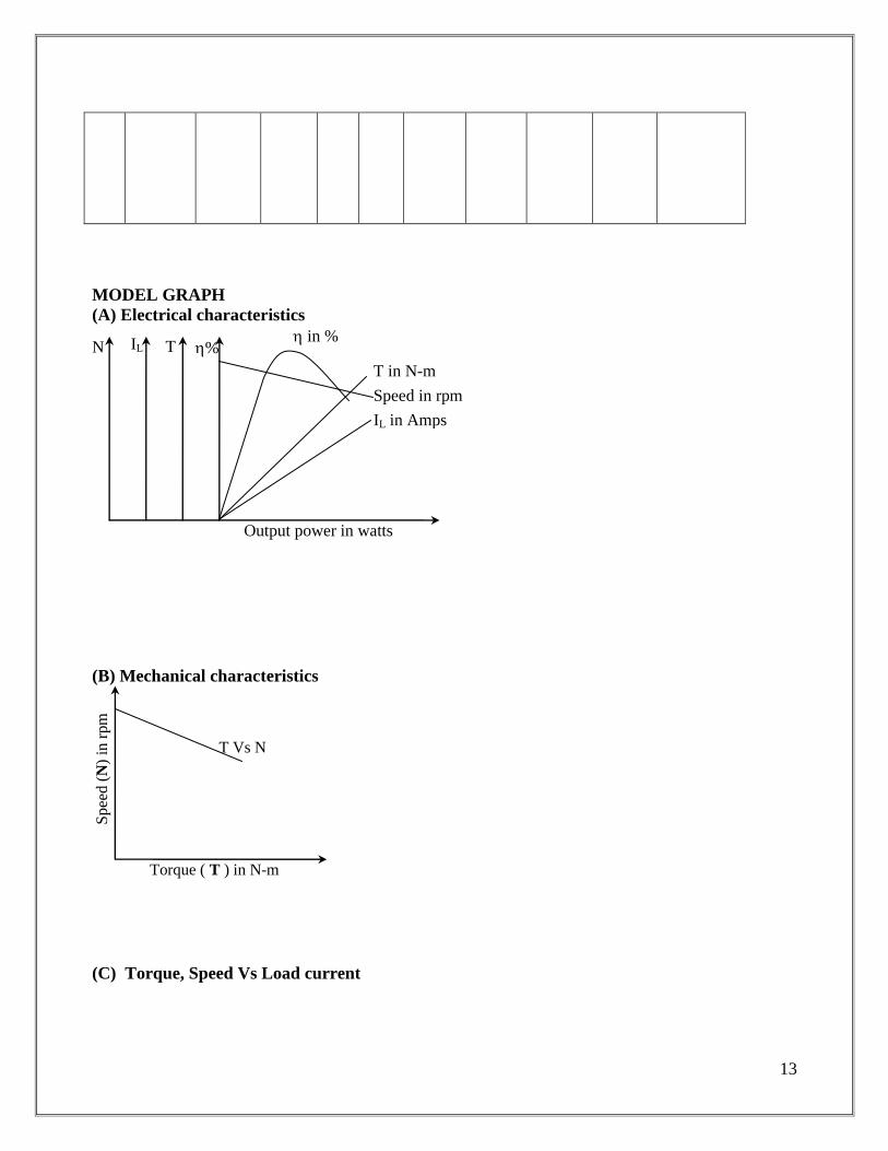
MODEL GRAPH
(A) Electrical characteristics
(B) Mechanical characteristics
(C) Torque, Speed Vs Load current
in %
T in N-m
Speed in rpm
IL in Amps
N IL T %
Output power in watts
T Vs N
Sp
eed
(N
) in
rpm
Torque ( T ) in N-m

14
Model calculation:
Graph:
Output Vs η%
Output Vs T
Output Vs N
Output Vs IL
Torque Vs N
Result:
Ex. No: 3
Date:
SWINBURNE’S TEST AND SPEED CONTROL OF DC SHUNT MOTOR
Aim
To conduct Swinburne’s test and predetermine the performance characteristics of DC
machine and speed control of DC motor
Exercise
1. Predetermine efficiency at various load current while operating as a motor and generator and
plot a graph output Vs η%
2. Draw the following curves for
a. If Vs N at Va = 0.8 Va and 1Va
b. Va Vs N at 0.8 If and If
Apparatus Required:
Sl.no Name of the component type Range Quantity
To
rqu
e (T
) i
n N
-m
Sp
eed
(N
) i
n r
pm
IL Vs N
Load current (IL) in Amps
IL Vs T
15
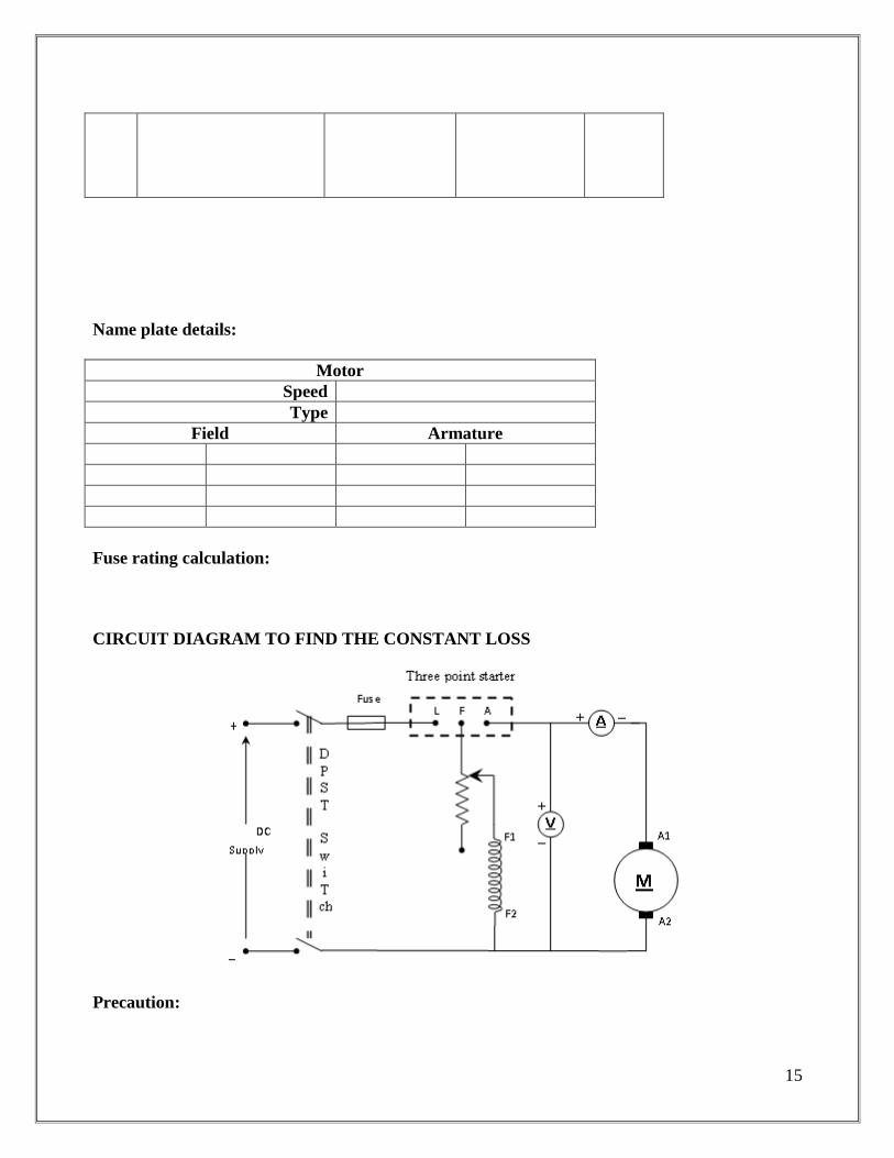
Name plate details:
Motor
Speed
Type
Field Armature
Fuse rating calculation:
CIRCUIT DIAGRAM TO FIND THE CONSTANT LOSS
Precaution:

16
Starter should be in off position before switching on the supply.
The DPST switch must be kept open.
The motor field rheostat must be kept at minimum resistance position
The motor armature rheostat must be kept at maximum resistance position.
Before connecting the meters check the polarity and zero error.
Procedure
Connections are given as per the circuit diagram.
Observe the precaution and switch ON the supply.
By adjusting the field rheostat get the motor speed to rated speed
A. Armature Control Method
Keep the Field Current Constant
By adjusting armature rheostat the speed and armature voltage are noted.
Repeat the same procedure for various positions.
B. Field Control Method
Keep the armature voltage constant.
By adjusting the field rheostat various field currents and voltage are noted.
Repeat the same procedure for various positions
Tabulation for Armature Control Method
Field current I1 Field current I2
Armature
voltage Va Speed N in RPM
Armature
voltage Va
Speed N in
RPM
Tabulation for Field Control Method
Armature Voltage V1 Armature Voltage V2
Field Current If
In AMPS Speed N in RPM
Field Current
If In AMPS
Speed N in
RPM

17
Result:
Ex. No: 4
Date:
OC AND SC TESTS ON SINGLE PHASE TRANSFORMER
Aim:
To conduct open circuit and short circuit test and to predetermine the efficiency of the
transformer at desired load and power factor and to calculate the regulation at different power factor
Exercise
1. Determine the equivalent circuit of the transformer.
2. Predetermine the efficiency at different load at UPF and 0.8 Power factor lagging.
3. Predetermine the full load regulation at different power factor.
4. Draw the following curves
a. Output Vs η%
b. Power factor Vs %Regulation
Apparatus Required:
Sl.no Name of the component type Range Quantity
-
Name plate details:
Transformer

18
Fuse calculation for transformer (O.C and S.C test):
Primary current IP = KVA rating of the transformer /primary voltage.
Secondary current IS =KVA rating of transformer / secondary voltage.
O.C test
10 % of rated primary current
S.C test
125 % of rated secondary current
Formulae Used:
Open circuit test:
1. No load power factor ococ
oc
IV
W
)(cos 0
WOC = open circuit power in watts
VOC = open circuit voltage in volts
IOC = open circuit current in amps
2. No load working component resistance (RO); oOC
OC
OCosI
VR
in ohms
3. No load magnetizing component (XO); oOC
OC
OSinI
VX
in ohms
Short circuit test:
4. Equivalent impedance referred to HV side (Z02); SC
SC
OI
VZ 2 in ohms.
5. Equivalent resistance referred to HV side (R02); 22
SC
SCO
I
WR in ohms
6. Equivalent reactance referred to HV side (X02); 2
2
2
22 OOO RZX in ohms
7. Transformation ratio (K); 1
2
V
VK
8. Equivalent resistance referred to LV side (R01); 2
2
1K
RR O
O in ohms
9. Equivalent reactance referred to LV side (X01); 2
2
1K
XX O
O in ohms
Efficiency and regulation
10. Output power = )( CosKVAX in watts
11. Chopper loss = )( 2
SCWX in watts
12. Total loss WT = )( lossIronlossCu in watts
13. Efficiency = 100 lossTotalpowerOutput
powerOutputin %
14. Regulation = 100[
2
22
O
OOSC
V
SinXCosRIX in %

19
Precautions:
1. Auto transformer should be kept at zero volt position.
2. At the time of starting the experiment DPST switch kept open and transformer should be no
load.
3. High voltage and low voltage sides of the transformer should be properly used as primary or
secondary respective to experiments.
Procedure (for Open circuit Test)
Connections are given as per the circuit diagram.
Ensuring the precautions the supply is switched on by closing DPST switch.
Auto transformer is adjusted to energize the transformer with primary voltage on LV side.
Voltmeter, ammeter and wattmeter readings are noted at no load condition.
Auto transformer is gradually decreased to its initial position.
Switch off the supply by DPST.
Procedure (for Short CKT Test)
Connections are given as per the circuit diagram.
Ensuring the precautions the supply is switched on by closing DPST switch.
Auto transformer is adjusted to energize the transformer with primary current on the HV
side.
Voltmeter, ammeter and wattmeter readings are noted at no load condition.
Auto transformer is gradually decreased to its initial position.
Switch off the supply by DPST.
Circuit diagram for open circuit test of 1 transformer
Circuit diagram for short circuit test of 1 transformer

20
Tabulation for OC Test multiplication factor:
Sl.
no
Open circuit
primary current
(IOC)
In Amps
Open circuit
primary voltage
(VOC) in Volts
Open circuit power
(Woc) in Watts Open circuit
Secondary
voltage in volts Observed Actual
Tabulation for SC Test multiplication factor:
Sl.
No
Short circuit
primary current
(ISC)
In Amps
Short circuit
primary voltage
(VSC) in Volts
Short circuit power
(Wsc) in Watts Short circuit
Secondary
Current in Amps Observed Actual
Predetermination of efficiency:
Core (or) Iron loss (Wi) = Watts, KVA rating of Transformer = .
Rated Short circuit current = Amps Short Circuit power (WSC) = .
Fraction
of load/
Load
factor
(X)
Short
circuit
current
(ISC X)
in Amps
Output
power )( CosKVAX in
watts
Copper
loss
)( 2
SCWX
in watts
Total loss
SCiT WWW
in watts
Efficiency
TWpo
po
/
/ X 100
in % 0.2 0.4 0.6 0.8 1

21
¼
½
¾
1
Tabulation to predetermine % Voltage regulation:
ISC = RO2= XO2= V2O=
Fractio
n of
load
(X)
Value of Cos Value of Sin
% of Regulation
100[
2
22
O
OOSC
V
SinXCosRIX
1 0.
8
0.
6
0.
4
0.
2 1
0.
8
0.
6 0.4 0.2 1
0.8 0.6 0.4 0.2
Lag Lead Lag Lead Lag Lead Lag Lead
¼
½
¾
1
Model graph
1) Efficiency 2) Regulation

22
Result:
EXPT NO: 4.b
Date :
LOAD TEST ON A SINGLE PHASE TRANSFORMER
AIM:
To conduct a direct load test on the given single phase transformer and to determine the
efficiency and regulation at different load conditions.
NAME PLATE DETAILS:
KVA rating =
Rated H.V side Voltage =
Rated L.V side Voltage =
INSTRUMENTS AND EQUIPMENTS REQUIRED:
S.No Equipment Type Range Quantity
1.
2.
3.
4.
5.
THEORY:
Direct load test is conducted to determine the efficiency characteristics and regulation
characteristics of the given transformer.
An ideal transformer is supposed to give constant secondary voltage irrespective of the load
current. But, practically the secondary voltage decreases as the transformer is loaded due to primary

23
and secondary impedance drops. Since these drops are dependent on load current, this variation in
terminal voltage is found using direct loading.
PRECAUTIONS:
1. Remove the fuse carriers before wiring and start wiring as per the circuit diagram.
2. Fuse Calculations: This being a load test, the required fuse ratings are 120% of rated current on
L.V side.
PROCEDURE:
1. The circuit connections are made as per the circuit diagram as shown in figure.
2. Keeping the autotransformer in its minimum position and the DPST switch in open position, the
main supply is switched ON.
3. By slowly and carefully operating the Auto transformer the rated voltage (115V) is applied to the
L.V side of the transformer.
4. Under this no-load condition one set of readings namely VH.V, IH.V, WH.Vs, VL.V, WL.V, are
recorded in the tabular column.
5. The DPST switch on the load side is now closed and the load is increased in gradual steps and at
each step all meter readings are noted down in the tabular column.
CIRCUIT DIAGRAM:
6. The procedure is continued until the current on the H.V side is equal to its full load value.
7. After the experiment is completed, the load is decreased to its minimum, the auto transformer is
brought back to its original position and then the main supply is switched OFF.
CALCULATIONS:-

24
I. EFFICIENCY CALCULATION:
i . The efficiency of the transformer for each set of reading is calculated and tabulated
using the expression,
100% XInput
Output
where,
The output of the transformer = VH.V * IH.V on the H.V side
The input of the transformer = WL.V = Wattmeter reading on the L.V side
ii . A Graph is plotted between the percentage efficiency and the output, taking %
efficiency on Y-axis and the output on X-axis, as shown in figure.
II . REGULATION CALCULATIONS: -
i . The regulation is calculated and tabulated for each set of readings using the
expression ,
100Re%
)(.
)(.)(.X
V
VVgulation
NoloadVH
loadVHNolaadVH
where,
VH.V(No-load) - is the no-load voltage on the H.V side .
VH.V(Load) - is the actual voltage on the H.V side under load condition .
ii . A Graph is plotted b=ween the percentage regulation and the output taking % regulation on
Y-axis and the output on X- axis as shown in figure.
TABULAR COLUMN:
Input Out put
(%)
%REG VL.V
IL.V
WL.V
(W)
VH.V
(V)
IH.V
(A)
WH.V
(watts)

25
MODEL CALCULATION:
MODEL GRAPH:
RESULT: -

26
Ex. No: 5
Date:
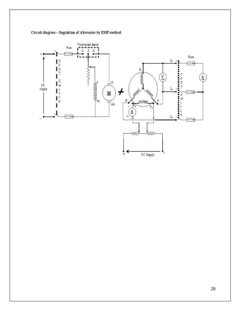
Predetermination of Regulation of Three Phase Alternator by EMF and MMF Methods
AIM:
To predetermine the regulation of three phase alternator by EMF and MMF method and also
to draw the vector diagrams.
Name plate details:
3 Alternator DC Shunt Motor
Fuse rating:
125 % of current (Full load current)
For dc shunt motor.
For alternator
Apparatus required:
s. no Name of the apparatus Type Range Quantity
Formulae used:
Emf method:
Armature resistance Ra = 1.6 Rdc where - Rdc is the resistance in DC supply.
Synchronous impedance Zs = Open circuit voltage (E1 (ph))/short circuit current (Isc)
Synchronous impedance Xs = (Zs2-Ra
2)
Open circuit voltage Eo = ((Vrated cos + Ia Ra) 2
+ (Vrated sin +IaXs)2)(For lagging power
factor)
Open circuit voltage Eo = ((Vrated cos + Ia Ra)2+(Vrated sin - IaXs)
2) (For leading power
factor)
Open circuit voltage Eo = ((Vrated cos + Ia Ra)2+( IaXs)
2) (For unity power factor)
Percentage regulation = (Eo-Vrated /Vrated)*100(For both EMF and MMF methods)
Precaution:

27
i. The motor field rheostat should be kept in the minimum resistance position.
ii. The alternator field potential divider should be in the maximum voltage position.
iii. Initially all switches are in open position.
Procedure for both emf and MMF method:
1. Note down the nameplate details of motor and alternator.
2. Connections are made as per the circuit diagram.
3. Give the supply by closing the dust switch.
4. Using the three point starter, start the motor to run at the synchronous speed by varying the
motor filed rheostat.
5. Conduct an open circuit test by varying the potential divider for various values of field
current and tabulate the corresponding open circuit voltage readings.
6. Conduct a short circuit test by closing the TPST switch and adjust the potential divider to set
the rated armature current, tabulate the corresponding field current.
7. Conduct a stator resistance test by giving connection as per the circuit diagram and tabulate
the voltage and current readings for various resistive loads.
Procedure to draw the graph for EMF method:
1. Draw the open circuit characteristics curve (generator voltage per phase Vs field current)
2. Draw the short circuit characteristics curve (short circuit current Vs field current)
3. From the graph find the open circuit voltage per phase (E1 (ph)) for the rated short circuit
current (Isc).
4. By using respective formulae find the Zs, Xs, Eo and percentage regulation.
Open circuit test:
S.NO Field current(If) Open circuit line
voltage (VOL)
Open circuit phase
voltage (Vo(ph))
Amps Volts Volts
28

29
Short circuit test:
Tabulation to find out the armature resistance (ra):
Procedure to draw the graph for MMF method:
1. Draw the open circuit characteristics curve (generator voltage per phase Vs field current)
2. Draw the short circuit characteristics curve (short circuit current Vs field current)
3. Draw the line OL to represent If’ which gives the rated generated voltage (V).
4. Draw the line LA at an angle (90Φ) to represent If” which gives the rated full load
current.(Isc) on short circuit [(90Φ) for lagging power factor and (90- Φ) for leading
power factor].
5. Join the points O and A and find the field current (If) measuring the distance OA that
gives the open circuit voltage (E0) from the open circuit characteristics.
6. Find the percentage regulation by using suitable formula.
Procedure to draw the vector diagram:
1. Draw the line OA that represents the rated voltage V.
2. Draw the line OB to represent the rated current Ia, which makes an angle Φ (it may
lags/leads in phase) with the voltage.
3. Draw the line AC to represent IRa drop, which is parallel to current axis (OB)
4. Draw the perpendicular line CD with the line AC (IRa drop) to represent IXs drop.
5. Join the points D and A to represent the IZs drop.
6. Join the points O and D and measure the length OD by voltage scale to find open circuit
voltage Eo.
7. Find the percentage regulation by using suitable using formulae.
RESULTANT TABULATION FOR REGULATION OF THREE PHASE ALTERNATOR BY EMF AND
MMF METHODS
S.No Field current(If)
Short Circuit Current
(120 to 150 % of rated
current ) (Isc)
Amps Amps
S.No Armature current
(I)
Armature voltage
(V)
Armature Resistance
Ra=V/I
Amps Volts Ohms

30
MODEL CALCULATION:
RESULT
Ex. No:6
Date:
Load Test on Three - Phase Induction Motor(Squirrel cage) Aim:
To conduct the load test on three phase squirrel cage induction motor and to draw the
performance characteristics curves.
Name plate details:
3 Induction Motor Auto Transformer
Fuse rating:
S.N
o Power
factor
EMF method MMF method
Lagging Leading unity Lagging Leading unity
1. 0.2
2. 0.4
3. 0.6
4. 0.8
5. 1.0
31
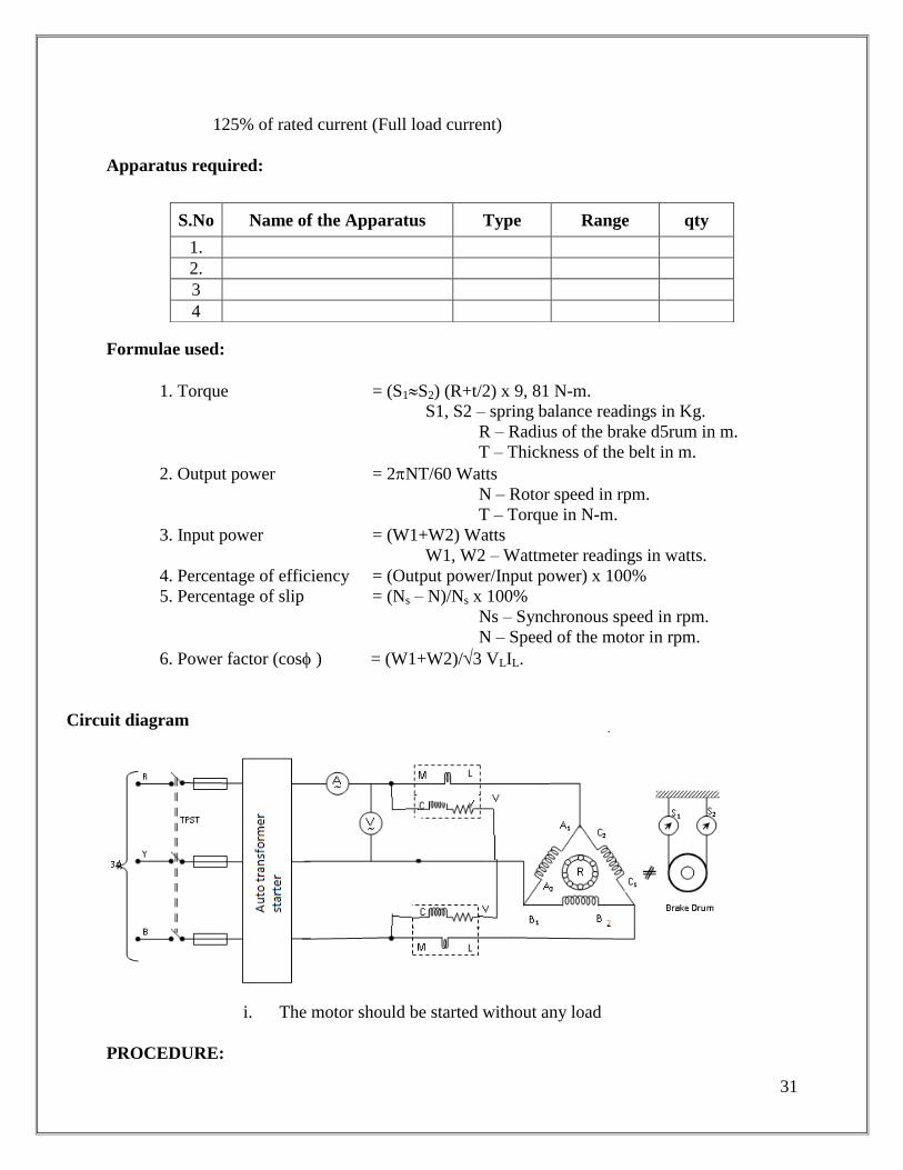
125% of rated current (Full load current)
Apparatus required:
Formulae used:
1. Torque = (S1S2) (R+t/2) x 9, 81 N-m.
S1, S2 – spring balance readings in Kg.
R – Radius of the brake d5rum in m.
T – Thickness of the belt in m.
2. Output power = 2NT/60 Watts
N – Rotor speed in rpm.
T – Torque in N-m.
3. Input power = (W1+W2) Watts
W1, W2 – Wattmeter readings in watts.
4. Percentage of efficiency = (Output power/Input power) x 100%
5. Percentage of slip = (Ns – N)/Ns x 100%
Ns – Synchronous speed in rpm.
N – Speed of the motor in rpm.
6. Power factor (cos ) = (W1+W2)/3 VLIL.
Circuit diagram
i. The motor should be started without any load
PROCEDURE:
S.No Name of the Apparatus Type Range qty
1.
2.
3
4

32
1. Note down the name plate details of motor.
2. Connections are made as per the circuit diagram.
3. The TPSTS is closed and the motor is started using On Line starter to run at rated speed.
4. At no load the speed, current, voltage and power are noted.
5. By applying the load, for various values of current the above-mentioned readings are noted.
6. The load is later released and the motor is switched off and the graph is drawn.
OBSERVATION:
Circumference of the brake drum =
Thickness of the belt =
MODELGRAPH:
The graph drawn for
Output power Vs speed
Output power Vs line current
Output power vs. Torque
Output power Vs power factor
Output power Vs Efficiency
Output power Vs %slip.
Mechanical Characteristics
Electrical Characteristics
Torque Vs Speed
Torque in N-m
Sp
eed
in r
pm

33
TABULATION FOR LOAD TEST ON THREE PHASE SQUIRREL CAGE INDUCTION
MOTOR
Multiplication factor: …………..
MODEL CALCULATION:
S. no
Load current
(IL)
Load voltage
(VL)
Input power (W1)
Input power (W2)
Speed of the
motor
(N)
Spring balance
reading
Torqu
e (T)
(s1~s
2) (R) (9.81)
Output
power
2NT/60
Efficienc
y () o/p
/ i/p x 100
Slip (S)
(Ns-N) / Ns x 100
Power
factor
(cos) i/p / VLIL
Observed Actual Observe
d Actual
S
1
S
2
S1
~S2
Amps Volts Watts Watts Watts Watts rpm K
g Kg Kg N-m Watts % %
Out put Power in Watts
%
%
Cos
Cos
N in
rpm
N i
n r
pm
T in N-
m
T i
n N
-m Sli
p
S
I L

34
RESULT:
Ex. No: 7
Date:
NO LOAD TEST AND BLOCKED ROTOR TEST ON THREE PHASE SQUIRREL
CAGE INDUCTION MOTOR
Aim:
To conduct the No Load test and Blocked rotor on three phase squirrel cage induction Motor
and to predetermine the performance characteristics at various loaded conditions.
Name plate details:
3 INDUTION MOTOR AUTO TRANSFORMERS
Fuse Rating calculation:
No Load: 10% of rated current (Full load current)
Load: 125% of rated current (Full load current)
Apparatus required:
S .No Name of the
Apparatus
Type Range Qty
1
2
3

35
4.
5.
Formulae used:
Open circuit test:
No load power factor ( Cos o) = Po / Vo Io
Working component current (IW) = Io(ph) x Cos o
Magnetizing current (Im) = Io (ph) x Sin o
No Load resistance (Ro) = Vo / Io (ph) Cos o in
No load reactance (Xo) = Vo / Io (ph) Sin o in
Where:
Vo – No load voltage per phase in volts
Io – no load current per phase in amps
Po – no load power per phase in watts
Short circuit test:
Motor equivalent impedance referred to stator (Zsc (ph)) = Vsc(ph) / Isc (ph) in
Motor equivalent resistance referred to stator (Rsc(ph)) = Psc(ph) / I2sc (ph) in
Motor equivalent reactance referred to stator (Xsc(ph)) = (Zsc(ph)2 / Rsc (ph)
2 )in
ROTOR resistance referred to stator (R2’ (ph)) = Rsc(ph) – R1 in
Rotor reactance referred to stator (X2’ (ph)) = Xsc(ph) / 2 = X1 in
Equivalent load resistance (RL’) = R2’ (1/s – 1) in
Where:
R1 – stator resistance per phase
X1 – stator reactance per phase
R1= R (ac) = 1.6 x R (dc) = R2’ (1/s-1) in
Slip (S) = (Ns-N) / Ns
Ns – Synchronous speed in rpm
N- Speed of the motor in rpm
Circuit diagram of No load test of 3 induction motor

36
Circuit diagram of Blocked Rotor test of 3 induction motor
Procedure:
Note down the name plate details of motor
1. For no-load or open circuit test by adjusting autotransformer, apply rated voltage and
note down the ammeter and wattmeter readings .In this test rotor is free to rotate.
2. For short circuit or blocked rotor test by adjusting autotransformer, apply rated current
and note down the voltmeter and wattmeter readings. In this test rotor is blocked.
3. After that make the connection to measure the stator resistance as per the circuit
Diagram
4. By adding the load through the loading rheostat note down the ammeter, voltmeter
reading for various values of load
Tabulation for No load test on three phase squirrel cage induction
Speed of the induction motor: …………..
Type of the stator connection: ……………
Multiplication factor: ………..
.
No
No
load
Current
(Io)
No
Load
Voltage
(Vo)
No load power Total No
Load
Power Po
=
(W1+W2)
No load
power /
phase
Po(ph)
=
(Po/3)
No load
Current
/ Phase
Io (ph)
No load
Voltage
/ phase
Vo (ph)
W1 W2
Observed Actual Observed Actual
Amps Volts Watts Watts Watts Watts Watts Watts Amps Volts

37
Tabulation for blocked rotor test on three phase squirrel cage induction
Type of the stator connection: ……………
Multiplication factor: ………..
No
Short
Circuit
Current
(Isc)
Short
Circuit
Voltage
(Vsc)
Short Circuit power Total
Short
Circuit
Power Po
=
(W1+W2)
Short
Circuit
power /
phase
Psc
(ph) =
(Psc/3)
Short
Circuit
Current
/ Phase
Isc (ph)
Short
Circuit
Voltage
/ phase
Vsc (ph)
W1 W2
Observed Actual Observed Actual
Amps Volts Watts Watts Watts Watts Watts Watts Amps Volts
Measurement of armature resistance
Tabulation to find out the stator resistance (r1)

38
S No Stator current (I) Stator Voltage (V)
Stator Resistance Rs
= V/I
Amps Volts Ohms
MODEL CALCULATION:
RESULT:
P R1
N
X1
230 V, 1,
50Hz
AC Supply
Equivalent circuit of 1 induction motor
Ro Xo
I1 R2’ X2’ I2
Io
RL’ = R2’ (1/s-1)

39
Expt. No: 8
Date:
TRANSFER FUNCTION OF SEPERATELY EXCITED DC GENERATOR
AIM:
To determine the transfer function of separately excited dc generator.
INSTRUMENTS & EQUIPMENTS REQUIRED:
S.
No
Name of the
Equipment
Range Type No of
Quantity
1
2.
3.
4.
5.
NAME PLATE DETAILS:
D.C.GENERATOR: D.C.MOTOR:
Rated voltage: Rated voltage:
Rated Current: Rated Current:
Rated Speed: Rated Speed:
Power Rating: Power Rating:
EXCITATION:
Voltage:
Current:

40
CIRCUIT DIAGRAM:
THEORY:
The transfer function for DC generator is defined as ratio of Laplace Transform
Of output V1(t) to Laplace Transform of Input Vf(t).
Transfer function = V1(t) / Vf(t)
The KVL to field circuit is
Vf(t) = If(t)Rf + Lf (dIf(t) /dt) ………………… 1
The armature induced emf Ea(t) is
Ea(t) If(t)
= Kf If(t) ………………… 2
where Kf is proportionality constant
The KVL to armature circuit is given by

41
Ea(t) = Ia(t) (Ra +RL) +La (dIa /dt) ………………… 3
The load voltage
V1(t) = Ia(t) RL ………………… 4
Ia(t) = IL(t)
Taking Laplace transform for equations 1,2,3 & 4 we get
Vf(s) = If(s) Rf + sLf If(s) ………………… 5
Ea(s) = Kf If(s) ………………… 6
Ea(s) = Ia(s) (Ra +RL) + sLa Ia(s) ………………… 7
V1(s) = Ia(s) RL ………………… 8
From the above equations we get
Ea(s) = Kf Vf(s) / (Rf + sLf ) ………………… 9
From 7 & 9
Kf Vf(s) / (Rf + sLf ) = Ia(s) (Ra +RL) + sLa Ia(s) ………………… 10
From equation 10
Ia(s) = Kf Vf(s) / (Rf + sLf ) [(Ra +RL) + sLa ] ………………… 11
V1(s) = Kf Vf(s) R1 / (Rf + sLf ) [(Ra +RL) + sLa ]
V1(s) / Vf(s) = Kf R1 / (Rf + sLf ) [(Ra +RL) + sLa ]
G(s) = V1(s) / Vf(s) = Kf R1 / (Rf + sLf ) [(Ra +RL) + sLa ………………… 12
G(s) = V1(s) / Vf(s) = (Kf RL / Lf La ) / (s + Rf / Lf) (s + (Ra +RL) /La )
Where Lf / Rf = field time constant, La / Ra = armature time constant
La / (Ra +RL) = total time constant
The above equation is known as the load transfer function of separately excited D.C generator.
PRECAUTIONS: (Not to be included in the Record)

42
1. Remove the fuse carriers before wiring and Start wiring as per the circuit diagram.
2. Check the positions of the various rheostats as specified.
3. The SPST switch is kept open at the time of starting the experiments.
4. Fuse calculations: As this is a no-load test the required fuse ratings are 20% of the rated
current.
5. Replace the fuse carriers with appropriate fuse wires after the circuit connections are checked
by the staff-in-charge.
PROCEDURE: (To Find K)
1. The circuit connections are made as per the circuit diagram in the shown figure 4.1.
2. Keeping the motor field rheostat in its minimum position, generator field rheostat in
maximum position and the starter in its OFF position, the main supply is switched ON to the
circuit.
3. The motor is started using the 3-point starter by slowly and carefully moving the starter
handle from its OFF to ON position.
4. The motor is brought to its rated speed by adjusting its rheostat and checked with the help of
a tachometer.
5. With the SPST switch open, the residual voltage is noted.
6. Now the SPST switch is closed and the generator field rheostat is gradually decreased in
steps and at each step the field current (If) and the corresponding induced EMF (Eg) are
recorded in the tabular column. This procedure is continued until the generator voltage
reaches 120% of its rated value.
7. After the experiment is completed the various rheostats are brought back to their original
position in sequence and then main supply is switched OFF.
CIRCUIT DIAGRAM:

43
Procedure: (To Find Ra & La)
1. The circuit connections are made as per the circuit diagram shown in figure 4.2.
2. Keeping autotransformer in minimum position, Main is switched ON.
3. Slowly adjust the variac and apply a small voltage (say 20V) to the armature winding.
4. Note down voltmeter, ammeter and wattmeter readings.
5. Bring the variac to minimum position and switch OFF the main supply.
Procedure: (To Find Rf & Lf)
1. The circuit connections are made as per the circuit diagram shown in figure 4.3.
2. Keeping autotransformer in minimum position, Main is switched ON.
3. Slowly adjust the variac and apply a small voltage (say 60V) to the field winding.
4. Note down voltmeter, ammeter and wattmeter readings.
5. Bring the variac to minimum position and switch OFF the main supply.
CALCULATION:
1. The open circuit characteristic is drawn to scale as shown in model graph.
2. A tangent is drawn to the linear portion of this OCC.
3. The slope of tangent is found using the relation Kf = Ea / If
4. The inductance and resistance of the field winding are calculated as follows:

44
W1=If2Rf
Rf =W1 / If2
Zf=Vf / If
Xf = (Zf2 – Rf
2)1/2
Lf = Xf / 2пf
5. The inductance of the armature winding is calculated using the equation
W2=Ia2Ra
Ra =W2 / Ia2
Za=Va / Ia
Xa = (Za2 – Ra
2)1/2
La = Xa / 2пf
6. The transfer function of the given separately excited D.C shunt generator is then evaluated by
substituting the values Kf, Rf, Lf, Ra & La in the standard equations
For no Load
TABULAR COLUMN :
Tabulation 1: OCC test
S.NO If (A) Eg (V)

45
Tabulation 2: To find Rf and Lf
Sl.No. W1 If Vf
Tabulation 3: To find Ra and La
Sl.No. W2 Ia Va
Model Graph
MODEL CALCULATION:
RESULT:
Thus the Transfer Function of Separately Excited D.C Shunt Generator is determined &
is given by
1. G(s)NL =
2. G(s)L =
Ex. No : 9A
Date:
TRANSFER FUNCTION OF ARMATURE CONTROLLED DC SERVO MOTOR
Aim:
To derive the transfer function of the given DC Servomotor and experimentally determine
the transfer function parameters
Apparatus required:
Sl no Apparatus Name Type/ Range Quantity

46
Name plate details:
Voltage 220 V
Current 19 A
Speed 1500 RPM
H.P 5 hp
Load Brake drum
Fuse calculation:
125 % of full load current
Formula used:
1) Transfer function ]KK)f)(JssLs[(R
K
(s)E
θ(s)G(s)
bToaa
T
a
Where:
KT – Torque constant calculated from graph (T Vs Ia)
Ra – Armature Resistance in
La – Inductance of Armature in H
fo – Viscous friction coefficient In N-M / rad /sec
J – Equivalent moment of inertia of motor and load referred to motor shaft (Kg-m2)
Kb – Is the back EMF constant.
2) Inertia constant: J
21
21
2
2
60
*
*
tt
tt
NN
IVJ
av
avav
In Kg/m
2

47
Where:
T1 – Time for fall of speed from N1 to N2 in no load condition
T2 – Time for fall of speed from N1 to N2 in load condition
2
21 VVVav
,
2
21 IIIav
2
21 NNNav
21 NNN
3) Frictional coefficient of motor and load
2
2
2
2
1
2
**60
2
NNJfo
In N-M / rad /sec
Where:
60
2 avN
4) Back EMF constant Kb
60
2 N
RIVK aa
b
Where:
V- Applied voltage in volts
Ia – Armature current in A
Ra – Armature Resistance in
N – Rated speed in RPM
Theory:
Armature control method is used when speed below the no load speed are required. As
the supplied voltage is normally constant, the voltage across the armature is varied by inserting a
variable rheostat in series with the armature circuit as shown. As controlled resistance is
increased, potential difference across the armature is decreased. For load of constant speed
approximately proportional to the potential difference across the armature.
Derivation of transfer function of armature controlled DC servo motor:
Consider the armature controlled d.c. servo motor shown in fig. below
In this system,
Ra = resistance of armature (Ω).
La = Inductance of the Armature Winding (H).
ia= = Armature Current(A).
if = Field Current (A).
ea = Applied Armature Voltage(V).
eb = Back EMF (volts).
TM = torque developed by armature (Nm).

48
θ = angular displacement of motor shaft (rad).
J = equivalent moment of inertia of motor and load referred to motor shaft
(Kg-m2)
fo = equivalent viscous friction coefficient of motor and load referred to motor
Shaft (N m/( rad/s))
In servo applications, the d.c motors are generally used in the linear range of the magnetization
curve. Therefore, the air gap flux Φ is proportional to field current
Φ= Kfif
where, Kf, is a constant.
The torque TM developed by the motor is proportional to the product of the armature
current and air gap flux,
TM = K1Kf if ia
where, K1, is a constant.
In the armature controlled d.c motor, the field current is kept constant, so that TM =
kTia
where, KT, is motor torque constant.
The motor back emf being proportional to speed is given as
dt
dθKe bb
where, Kb, is the back emf constant.
The differential equation of the armature circuit is
abaa
a
a eeiRdt
diL
The torque equation is
aTM02
2
iKTdt
dθf
dt
θdJ
Taking the Laplace transform and assuming zero initial conditions, we get
Eb(s) = Kb s θ(s)
(Las+Ra) Ia(s) = Ea(s) - Eb(s)
(Js2+fos) θ(s) = TM(s) = KTIa(s)
+
-
If (costant)
Ra
ea
La
θ ia
TM

49
The transfer function of the system is obtained as
]KK)f)(JssLs[(R
K
(s)E
θ(s)G(s)
bToaa
T
a
Assumptions:
The field current is constant.
The flux which is proportional to the field current is also constant.
The torque generated is proportional to the product of flux and the armature current
Tm ΦIa
T Ia
Tm = KtIa
Where Kt is the motor torque constant
Back EMF of the motor is proportional to the speed and the flux Eb Φ.
Precautions:
1) At the time of starting the motor should be at no load condition
2) Armature rheostat must be kept at maximum resistance position
3) Field rheostat must be kept at minimum resistance position
Procedure:
1) To find inertia constant [J]
Connections are made as per the circuit diagram
The DPST switch is switched ON. It is in the initial position at the time of starting.
After observing the precautions, switch on the DPST.
Adjust the field side rheostat and the armature side rheostat and allow the motor to run at
rated speed N1.
Open the DPST and observe the speed of the motor note the time taken for the speed to
fall down to any three values of the speed N2.
Adjust the rheostat to initial position and switch of the DPST.
Open the DPST and bring 2-2 position and immediately note down the reading
Repeat the steps 2, 3, 4.
Observe that the speed falls rapidly for the same values of speed noted in steps note down
the time taken, voltage and current.
Switch off the dc supply.
Inertia Constant is calculated using formula 21
21
2
2
60
*
*
tt
tt
NN
IVJ
av
avav
2) To Find Torque Constant [KT]
1. Connections are given as per the circuit diagram.

50
2. The DPST is switched on.
3. Adjust the armature side rheostat and keep in fixed position so that the value of Ia is
maintained constant through the experiment.
4. Note down If, Va, Ia in table.
5. Adjust the field rheostat and note down the Va, Ia, If and Speed.
6. Graph is drawn between the torque and If.
KT = T/If
3) To fined Back EMF constant [Kb]
The connections are given as per the circuit diagram
The D.C supply is given by closing the DPST switch
Run the motor at its rated speed by adjusting armature rheostat
At rated speed the readings of applied voltage and armature current were noted down
Back MEF constant is calculated using the formula
60
2 N
RIVK aa
b
4) To find armature resistance [Ra]
Connections are made as per the circuit diagram
The resistive should be in off position at the time of starting.
Adjust the load, for each values of load, note down the ammeter, voltmeter readings.
Armature resistance is calculated by using the formula
5) To find field impedance [Zf]
1. Connections are made as per the circuit diagram
2. Vary the auto transformer and note down the corresponding ammeter and voltmeter
readings.
3. Calculate the value of Zf = Vf /If and find the mean of Zf.
Circuit diagram for calculating inertia constant J

51
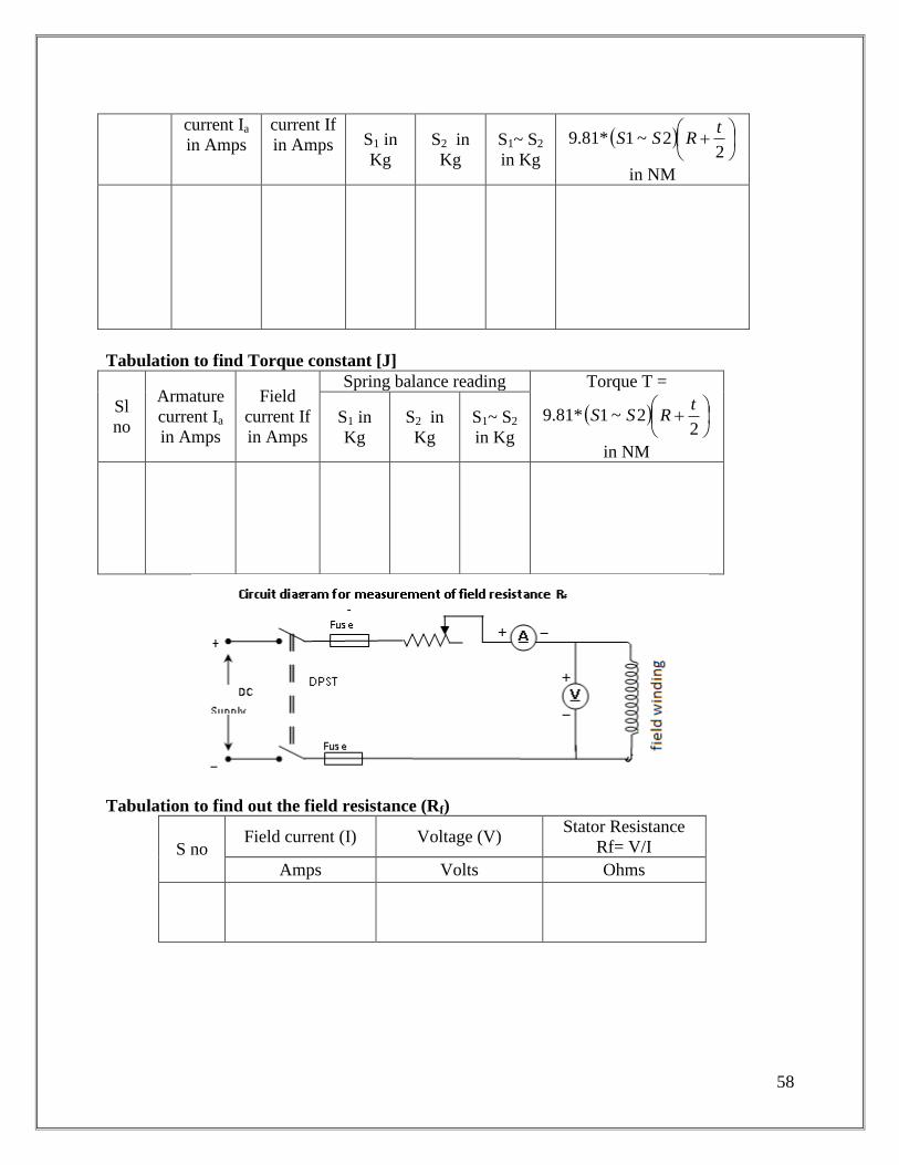
Tabulation to find Torque constant [J]
Sl no
Armature
current Ia
in Amps
Field
current If
in Amps
Spring balance reading Torque T =
9.81*
22~1
tRSS
in NM
S1 in
Kg
S2 in
Kg
S1~ S2
in Kg
Circuit diagram for find armature resistance Ra
Circuit diagram for find Impedance Za

52
Tabulation to find Back EMF constant [Kb]
Armature
Voltage Va in
Volts
Armature
current Ia in
Amps
Speed in RPM
Back EMF
Constant
60
2 N
RIVK aa
b
Tabulation to find Armature Resistance [Ra]
Armature
Voltage Va in
Volts
Armature
current Ia in
Amps
Armature
resistance Ra
= V * I in Ω
Tabulation to Find Armature Resistance [Za]
Armature
Voltage Va in
Volts
Armature
Current Ia in
Amps
Armature
Impedance Za
= V / I in Ω

53
Result:
Ex. No : 9B
Date:
TRANSFER FUNCTION OF FIELD CONTROLLED DC SERVO MOTOR
Aim:
To derive the transfer function of the given D.C Servomotor and experimentally determine
the transfer function parameters
Apparatus required:
Sl No. Apparatus Name Type/ Range Quantity
Name plate details:
Voltage
Current
Speed
H.P
Load
Fuse calculation:
125 % of full load current
T
Ia
T in
N-M
Ia in
Amps
Model graph Torque Vs Ia
a
TI
TK
T

54
Formula used:
1) Transfer function 1)s1)(τss(τ
K
(s)E
θ(s)
mef
m
f
Where:
Km = KT’/Rff – Motor Gain Constant
τf = Lf/Rf –Time Constant of Field Circuit
τme = J/f – Mechanical Time Constant.
lf – inductance of field winding in H
Rf – Resistance of field winding in
J – Equivalent of inertia of motor and load referred to motor shaft (kg-m2).
f – Equivalent viscous friction coefficient of motor and load referred to motor shaft rad/s
Nm
2) Inertia constant: J
21
21
2
2
60
*
*
tt
tt
NN
IVJ
av
avav
In Kg/m
2
Where:
T1 – Time for fall of speed from N1 to N2 in no load condition
T2 – Time for fall of speed from N1 to N2 in load condition
2
21 VVVav
,
2
21 IIIav
2
21 NNNav
21 NNN
3) Frictional coefficient of motor and load
2
2
2
2
1
2
**60
2
NNJfo
In N-M / rad /sec
Where:
60
2 avN
Derivations of transfer function of Field Controlled D C motor:
In this system
Rf - Field Winding Resistance (Ω)
Lf -Field Winding Inductance (H).
e- Field control voltage. (V).
if - Field Current(A).
TM - Torque Developed By Motor (Nm).
J- Equivalent of inertia of motor and load referred to motor shaft (kg-m2).
f- Equivalent viscous friction coefficient of motor and load referred to motor shaft rad/s
Nm

55
θ - Angular displacement of motor shaft (rad).
In this field controlled motor, the armature current is fed from a constant current source.
Therefore
TM = K1Kfiaif = KT’ if where KT’ is a constant.
The equation for the field circuit is
ffff
f eiRdt
diL
The torque equation is
(s)I 'KTdt
dθf
dt
θdJ fTM2
2
Taking the Laplace transform and assuming zero initial conditions we get
(Lfs + Rf) If(s) = Ef(s)
(Js2+fs) θ(s) = TM(s) = KT’ If(s)
From the above equations, the transfer function of the motor is obtained as
1)s1)(τss(τ
K
(s)E
θ(s)
mef
m
f
where
Km = KT’/Rff – motor gain constant
τf = lf/Rf –time constant of field circuit
τme = J/f – mechanical time constant.
Theory:
The speed of the dc motor is directly proportional to the armature voltage and inversely
proportional to the flux. In the field controlled dc motor, armature voltage is kept constant and
the speed is varied by varying the flux of the machine.
Precautions:
The DPST is kept open initially.
The field rheostat is kept at maximum position.
Procedure:
Rf
ef Lf
θ If
ia( constant)
TM
J,f

56
1) To find inertia constant [J]
Connections are made as per the circuit diagram
The DPST switch is switched ON. It is in the initial position at the time of starting.
After observing the precautions, switch on the DPST.
Adjust the field side rheostat and the armature side rheostat and allow the motor to run at
rated speed N1.
Open the DPST and observe the speed of the motor note the time taken for the speed to
fall down to any three values of the speed N2.
Adjust the rheostat to initial position and switch of the DPST.
Open the DPST and bring 2-2 position and immediately note down the reading
Repeat the steps 2, 3, 4.
Observe that the speed falls rapidly for the same values of speed noted in steps note down
the time taken, voltage and current.
Switch off the dc supply.
Inertia Constant is calculated using formula 21
21
2
2
60
*
*
tt
tt
NN
IVJ
av
avav
2) To Find Torque Constant [KT]
7. Connections are given as per the circuit diagram.
8. The DPST is switched on.
9. Adjust the armature side rheostat and keep in fixed position so that the value of Ia is
maintained constant through the experiment.
10. Note down If, Va, Ia in table.
11. Adjust the field rheostat and note down the Va, Ia, If and Speed.
12. Graph is drawn between the torque and If.
KT = T/If
3) To find armature resistance [Rf]
Connections are made as per the circuit diagram
The resistive should be in off position at the time of starting.
Adjust the load, for each values of load, note down the ammeter, voltmeter readings.
Armature resistance is calculated by using the formula Rf= V/I
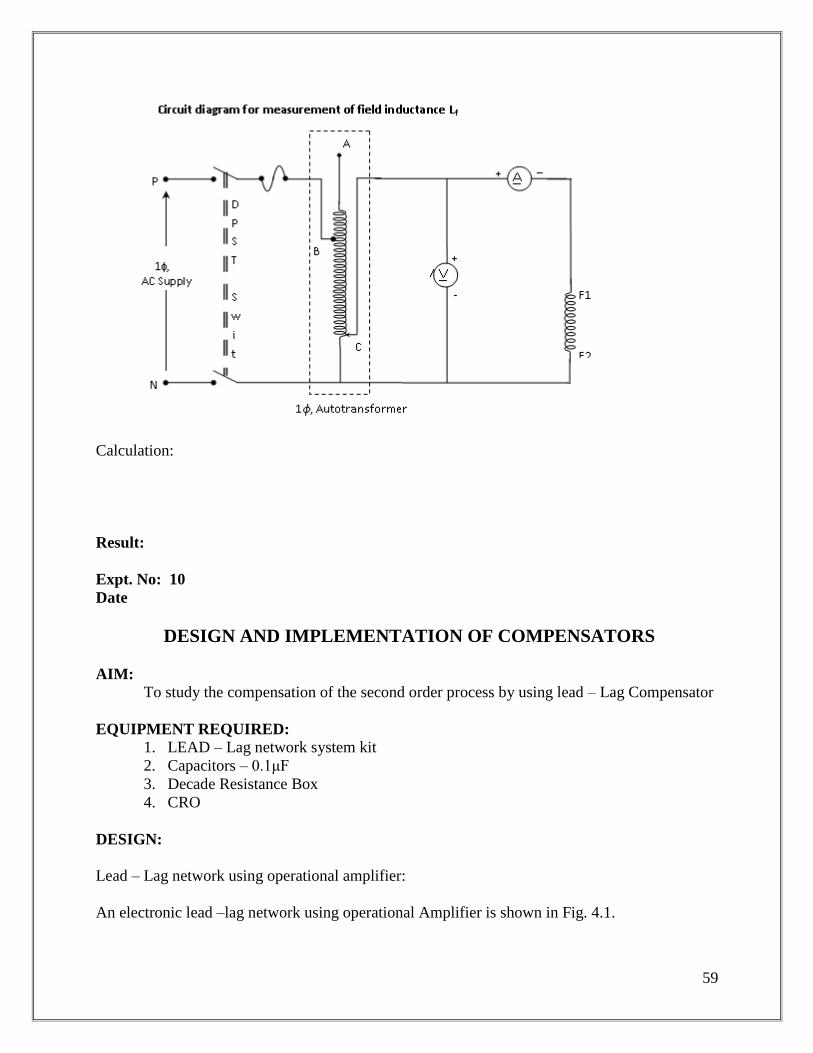
4) To find field impedance [Lf]
1. Connections are made as per the circuit diagram
2. Vary the auto transformer and note down the corresponding ammeter and voltmeter
readings.
3. Calculate the value of Zf = Vf /If and find the mean of Zf.

57
Tabulation to find Torque constant [J]
Sl no Armature Field Spring balance reading Torque T =
T
If
T in
N-M
If in
Amps
Model graph Torque Vs If
58
current Ia
in Amps
current If
in Amps S1 in
Kg
S2 in
Kg
S1~ S2
in Kg
9.81*
22~1
tRSS
in NM
Tabulation to find Torque constant [J]
Sl
no
Armature
current Ia
in Amps
Field
current If
in Amps
Spring balance reading Torque T =
9.81*
22~1
tRSS
in NM
S1 in
Kg
S2 in
Kg
S1~ S2
in Kg
Tabulation to find out the field resistance (Rf)
S no Field current (I) Voltage (V)
Stator Resistance
Rf= V/I
Amps Volts Ohms
59
Calculation:
Result:
Expt. No: 10
Date
DESIGN AND IMPLEMENTATION OF COMPENSATORS
AIM:
To study the compensation of the second order process by using lead – Lag Compensator
EQUIPMENT REQUIRED:
1. LEAD – Lag network system kit
2. Capacitors – 0.1μF
3. Decade Resistance Box
4. CRO
DESIGN:
Lead – Lag network using operational amplifier:
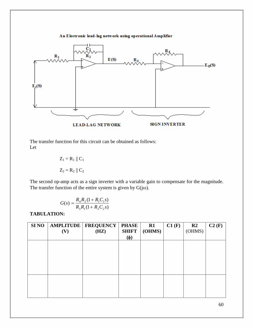
An electronic lead –lag network using operational Amplifier is shown in Fig. 4.1.
60
The transfer function for this circuit can be obtained as follows:
Let
Z1 = R1 || C1
Z2 = R2 || C2
The second op-amp acts as a sign inverter with a variable gain to compensate for the magnitude.
The transfer function of the entire system is given by G(j).
)1(
)1()(
2213
1124
sCRRR
sCRRRsG
TABULATION:
SI NO AMPLITUDE
(V)
FREQUENCY
(HZ)
PHASE
SHIFT
()
R1
(OHMS)
C1 (F) R2
(OHMS) C2 (F)

61
We have
)1(
)1()(
22
231
22
142
TRR
TRRjG
Where
T1 = R1C1
T2 = R2C2 and
Thus the steady state output is
)tantan()1(
)1()( 2
1
1
1
22
231
22
142
TTtSin
TRR
TRRtYss
for an input Esint.
From this expression, we find that if T1>T2, then 2
1
1
1 tantan TT >0. Thus if T1>T2, then the
network is a lead network. If T1 <T2, the network is a lag network.
Determination of values for angle compensation:
Frequency of sine wave (f)= 20Hz.
Phase angle to be compensated =14.50
sec023.0
)*20*2(tan)1.0*20*2(tan5.14
sec1.0
)2(tan)2(tan
2
2
11
1
2
1
1
1
T
T
TLet
fTfT
Hence the values of T1 and T2 are chosen from which the values of R1, R2, C1, and C2 can be
determined. For Example,
T1 = R1C1 = 0.1; If C1 = 0.1μF, R1=1MΩ
T2 = 0.023sec
If C2 = 0.1 μF, R2 =230KΩ.
These values produce a phase lead of 14.5o, which is the desired compensation angle.
PROCEDURE:

62
1. Switch ON the power to the instrument.
2. Connect the individual blocks using patch chords bypassing the compensating
network and gain as shown in fig. 4.2.
3. Give a sinusoidal input as the set value to the error detector.
4. Measure the amplitude and frequency of the input signal.
5. Measure the amplitude and phase difference of the output signal with respect to the
input signal using DSO.
6. Using the technique explained previously, calculate the values of R1, R2, C2, and C1
to compensate for the phase shift of the output signal.
7. Connects the components at the points provided.
8. Now include the compensation block in the forward path before the process using
patch chords as shown in fig.4.2.
9. Observe the compensated wave form through DSO.
CALCULATION: (frequency = Hz)
CALCUALTION : (frequency = Hz)
RESULT:
Thus the compensator is designed for the given process and the performance of
the compensated system is found to work satisfactorily.
Frequency : Hz R1 = C1 =
R2 = C2 =
Frequency : Hz R1 = C1 =
R2 = C2 =

63
Expt No: 11 Date
STUDY OF D.C MOTOR STARTERS
AIM:
To study the different kinds of D.C motor starters
EQUIPMENT AND APPARATUS REQUIRED :
Sl No. Name of the apparatus Quantity
1 Two Point starter 1
2 Three Point starter 1
3 Four Point starter 1
THEORY :
The value of the armature current in a D.C shunt motor is given by
Ia = ( V – Eb )/ Ra
Where V = applied voltage.
Ra = armature resistance.
E b = Back .e.m.f .
In practice the value of the armature resistance is of the order of 1 ohms and at the instant of
starting the value of the back e.m.f is zero volts. Therefore under starting conditions the value of
the armature current is very high. This high inrush current at the time of starting may damage the
motor. To protect the motor from such dangerous current the D.C motors are always started
using starters.
The types of D.C motor starters are
i) Two point starters
ii) Three point starters
iii) Four point starters.
The functions of the starters are
i) It protects the from dangerous high speed.
ii) It protects the motor from overloads.
i) TWO POINT STARTERS: ( refer fig 1)
It is used for starting D.C. series motors which has the problem of over speeding due to the loss
of load from its shaft. Here for starting the motor the control arm is moved in clock-wise
direction from its OFF position to the ON position against the spring tension. The control arm is
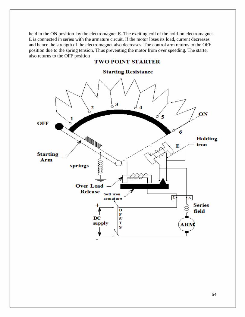
64
held in the ON position by the electromagnet E. The exciting coil of the hold-on electromagnet
E is connected in series with the armature circuit. If the motor loses its load, current decreases
and hence the strength of the electromagnet also decreases. The control arm returns to the OFF
position due to the spring tension, Thus preventing the motor from over speeding. The starter
also returns to the OFF position

65
when the supply voltage decreases appreciably. L and F are the two points of the starter which are connected with the motor terminals.
66
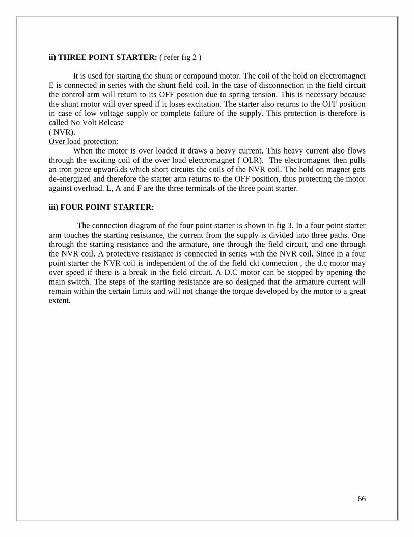
ii) THREE POINT STARTER: ( refer fig 2 )
It is used for starting the shunt or compound motor. The coil of the hold on electromagnet
E is connected in series with the shunt field coil. In the case of disconnection in the field circuit
the control arm will return to its OFF position due to spring tension. This is necessary because
the shunt motor will over speed if it loses excitation. The starter also returns to the OFF position
in case of low voltage supply or complete failure of the supply. This protection is therefore is
called No Volt Release
( NVR).
Over load protection:
When the motor is over loaded it draws a heavy current. This heavy current also flows
through the exciting coil of the over load electromagnet ( OLR). The electromagnet then pulls
an iron piece upwar6.ds which short circuits the coils of the NVR coil. The hold on magnet gets
de-energized and therefore the starter arm returns to the OFF position, thus protecting the motor
against overload. L, A and F are the three terminals of the three point starter.
iii) FOUR POINT STARTER:
The connection diagram of the four point starter is shown in fig 3. In a four point starter
arm touches the starting resistance, the current from the supply is divided into three paths. One
through the starting resistance and the armature, one through the field circuit, and one through
the NVR coil. A protective resistance is connected in series with the NVR coil. Since in a four
point starter the NVR coil is independent of the of the field ckt connection , the d.c motor may
over speed if there is a break in the field circuit. A D.C motor can be stopped by opening the
main switch. The steps of the starting resistance are so designed that the armature current will
remain within the certain limits and will not change the torque developed by the motor to a great
extent.

67
STUDY OF INDUCTION MOTOR STARTERS
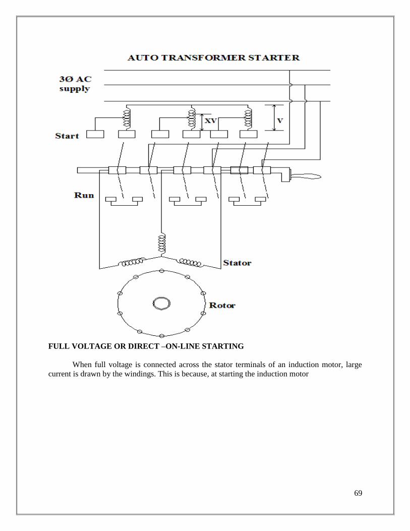
AUTO –TRANSFORMER STARTING

68
An auto transformer starter consists of an auto transformer and a switch as shown in the
fig. When the switch S is put on START position, a reduced voltage is applied across the motor
terminals. When the motor picks up speed, say to 80 per cent of its mornal speed, the switch is
put to RUN position. Then the auto-transformer is cut out of the circuit and full rated voltage
gets applied across the motor terminals.
(Ref. To text book for fig)
The circuit dia in the fig is for a manual auto-transformer starter. This can be made push button
operated automatic controlled starter so that the contacts switch over from start to run position as
the motor speed picks up to 80% of its speed. Over-load protection relay has not been shown in
the figure. The switch S is air-break type for small motors and oil break type for large motors.
Auto transformer may have more than one tapping to enable the user select any suitable starting
voltage depending upon the conditions.
Series resistors or reactors can be used to cause voltage drop in them and thereby allow low
voltage to be applied across the motor terminals at starting. These are cut out of the circuit as the
motor picks up speed.
STAR- DELTA METHOD OF STARTING:
The startor phase windings are first connected in star and full voltage is connected across its free
terminals. As the motor picks up speed, the windings are disconnected through a switch and they
are reconnected in delta across the supply terminals. The current drawn by the motor from the
lines is reduced to as compared to the current it would have drawn if connected in delta.The
motor windings, first in star and then in delta the line current drawn by the motor at starting is
reduced to one third as compared to starting current with the windings delta-connected.
In making connections for star-delta starting, care should be taken such that sequence of supply
connections to the winding terminals does not change while changing from star connection to
delta connection. Otherwise the motor will start rotating in the opposite direction, when
connections are changed from star to delta. Star-delta starters are available for manual operation
using push button control. An automatic star – delta starter used time delay relays(T.D.R)
through which star to delta connections take place automatically with some pre-fixed time delay.
The delay time of the T.D.R is fixed keeping in view the starting time of the motor.
(Ref. To text book for fig)
69
FULL VOLTAGE OR DIRECT –ON-LINE STARTING
When full voltage is connected across the stator terminals of an induction motor, large
current is drawn by the windings. This is because, at starting the induction motor

70

71
behaves as a short circuited transformer with its secondary, i.e. the rotor separated from the
primary, i.e. the stator by a small air-gap.
At starting when the rotor is at standstill, emf is induced in the rotor circuit exactly
similar to the emf induced in the secondary winding of a transformer. This induced emf of the
rotor will circulate a very large current through its windings. The primary will draw very large
current from the supply mains to balance the rotor ampere-turns. To limit the stator and rotor
currents at starting to a safe value, it may be necessary to reduce the stator supply voltage to a
low value. If induction motors are started direct-on-line such a heavy starting current of short
duration may not cause harm to the motor since the construction of induction motors are rugged.
Other motors and equipment connected to the supply lines will receive reduced voltage. In
industrial installations, however, if a number of large motors are started by this method, the
voltage drop will be very high and may be really objectionable for the other types of loads
connected to the system. The amount of voltage drop will not only be dependent on the size of
the motor but also on factors like the capacity of the power supply system, the size and length of
the line leading to the motors etc. Indian Electricity Rule restricts direct on line starting of 3
phase induction motors above 5 hp.
RESULT:
Thus the construction and working of different starters for starting D.C series, shunt,
compound and three phase induction motors are studied.
Ex. No : 12
Date:
Digital Simulation of Linear Systems

72
Aim:
To digitally simulate the time response characteristics of higher-order MIMO linear systems
using state – variable formulation
Equipments required:
PC system with mat lab
Theory: Introduction to MATLAB & SIMULINK
What is MATLAB?
MATLAB® is a high-performance language for technical computing. It integrates computation, visualization, and programming in an easy-to-use environment where problems and solutions are expressed in familiar mathematical notation. Typical uses include
Math and computation
Algorithm development
Data acquisition
Modeling, simulation, and prototyping
Data analysis, exploration, and visualization
Scientific and engineering graphics
Application development, including graphical user interface building
MATLAB is an interactive system whose basic data element is an array that does not
require dimensioning. This allows you to solve many technical computing problems, especially
those with matrix and vector formulations, in a fraction of the time it would take to write a
program in a scalar no interactive language such as C or FORTRAN.
The name MATLAB stands for matrix laboratory. MATLAB was originally written to provide
easy access to matrix software developed by the LINPACK and EISPACK projects. Today,
MATLAB engines incorporate the LAPACK and BLAS libraries, embedding the state of the art
in software for matrix computation.
MATLAB has evolved over a period of years with input from many users. In university
environments, it is the standard instructional tool for introductory and advanced courses in
mathematics, engineering, and science. In industry, MATLAB is the tool of choice for high-
productivity research, development, and analysis.
MATLAB features a family of add-on application-specific solutions called toolboxes. Very
important to most users of MATLAB, toolboxes allow you to learn and apply specialized
technology. Toolboxes are comprehensive collections of MATLAB functions (M-files) that
extend the MATLAB environment to solve particular classes of problems. Areas in which

73
toolboxes are available include signal processing, control systems, neural networks, fuzzy logic,
wavelets, simulation, and many others.
Starting MATLAB
Instructions for starting MATLAB® depend on your platform. For a list of supported
platforms, see the system requirements in the installation documentation, or the Products section
of the MathWorks Web site, http://www.mathworks.com
Starting MATLAB on Windows Platforms To start MATLAB on a Microsoft Windows
platform, select the Start -> Programs -> MATLAB 7.0 -> MATLAB 7.0, or double-click the
MATLAB shortcut icon on your Windows desktop. The shortcut was automatically created by
the installer.
Transfer function of the given 4 systems
Transfer function:
s - 1
-------------
s^2 + s + 6.5
Transfer function:
s + 7.5
-------------
s^2 + s + 6.5
Transfer function:
s + 3.553e-015
--------------
s^2 + s + 6.5
Transfer function:
s^2 + s + 13
-------------
s^2 + s + 6.5
Matlab program:
Open new m file and type the given program % State Space Analysis of MIMO System %-----X^ = Ax+Bu; y =Cx+Du -------%
A=[-1 -1; 6.5 0]; %----State Matrix(nxn)-----% B=[1 1;1 0]; %----Input Mtrix(nxm)------% C=[1 0;0 1]; %----Output Matrix(pxn) ------% D=[0 0;0 1]; %----Transistion Matrix(pxm)---%

74
step(A,B,C,D,1) hold step(A,B,C,D,2) title('Step Response of MIMO System') grid [num1,den1]=ss2tf(A,B,C,D,1) [num2,den2]=ss2tf(A,B,C,D,2) n1=num1(1,:) n2=num1(2,:) n3=num2(1,:) n4=num2(2,:) d1=den1(1,:) d2=den2(1,:) tf1=tf(n1,d1) tf2=tf(n2,d1) tf3=tf(n3,d2) tf4=tf(n4,d2)
For impulse response
response MIMO system % State Space Analysis of MIMO System %-----X^ = Ax+Bu; y =Cx+Du -------% A=[-1 -1; 6.5 0];%----State Matrix(nxn)-----% B=[1 1;1 0];%----Input Mtrix(nxm)------% C=[1 0;0 1];%----Output Matrix(pxn) ------% D=[0 0;0 1];%----Transistion Matrix(pxm)---% impulse(A,B,C,D,1) hold impulse(A,B,C,D,2) title('Impulse Response of MIMO System') grid [num1,den1]=ss2tf(A,B,C,D,1) [num2,den2]=ss2tf(A,B,C,D,2) n1=num1(1,:) n2=num1(2,:) n3=num2(1,:) n4=num2(2,:) d1=den1(1,:) d2=den2(1,:) tf1=tf(n1,d1) tf2=tf(n2,d1) tf3=tf(n3,d2) tf4=tf(n4,d2)

75
Step Response of MIMO System
Time (sec)
Am
plit
ude
0 2 4 6 8 10 12-0.5
0
0.5
1
1.5
2
2.5
3
Current plot held
num1 =
0 1.0000 -1.0000
0 1.0000 7.5000
den1 =

76
1.0000 1.0000 6.5000
num2 =
0 1.0000 0.0000
1.0000 1.0000 13.0000
den2 =
1.0000 1.0000 6.5000
n1 =
0 1.0000 -1.0000
n2 =
0 1.0000 7.5000
n3 =
0 1.0000 0.0000
n4 =
1.0000 1.0000 13.0000
d1 =
1.0000 1.0000 6.5000
d2 =
1.0000 1.0000 6.5000
Transfer function:
s - 1
-------------
s^2 + s + 6.5
Transfer function:
s + 7.5
-------------
s^2 + s + 6.5
Transfer function:
s + 3.553e-015
--------------
s^2 + s + 6.5
Transfer function:
s^2 + s + 13
-------------
s^2 + s + 6.5
Result:

77
Ex. No : 13
Date: Stability Analysis of Linear Systems
Aim
To analyse the stability of linear systems using Bode, Root locus, Nyquist plots
Equipments required:
PC system with mat lab
Program:
STABILITY ANALYSIS Program For Nyquist Plot. %---Given System G(s)=1/(s^2+0.8s+1)-----%
%--------Nyquist plot-----------%
num=[0 0 1];
den=[1 0.8 1];
nyquist(num,den);
axis(v)
grid
title('Nyquist plot of G(s)=1/(s^2+0.8s+1)')
xlabel('Real axis')
ylabel('Imag axis')
hold on Program for Root Locus %---conditionally stable system--%
%---Given System G(s)=k(s^2+2s+4)/[s(s+4)(s+6)(s^2+1.4s+1)-----%
clc;
close all;

78
clear all;
%--------Root Locus----------%
numz=[0 0 0 1 2 4];
denp=[1 11.4 39 43.6 24 0];
r=rlocus(numz,denp);
plot(r,'o');
axis(v)
grid
title('Root locus plot of G(s)=k(s^2+2s+4)/[s(s+4)(s+6)(s^2+1.4s+1)]')
xlabel('real axis')
ylabel('imag axis')
hold
Program for Bode Plot
%---Given System=s^3+2s+3/(s^5+s^4+s^3+s^2+s+1)---%
%--------Bode Plot ----------%
numg=[1 0 2 3];
deng=[1 1 1 1 1 1 ];
'G(s)'
u=tf(numg,deng);
bode(u)
grid
hold
title('Bode plot of G(s)=s^3+2s+3/(s^5+s^4+s^3+s^2+s+1)')
[Gm,Pm,Wcg,Wcp] = margin(u)
Gm_dB = 20*log10(Gm)
Program For Polar Plot
format compact
set(gcf,'Toolbar','none','Name','Polar Plot', ...
'NumberTitle','off','Position',[10,350,350,300]);
theta = 2*pi*linspace(0,1,30);
r = 2*(1 + cos(theta));
Polar(theta,r,'r-')
set(gca,'Position',[0.1 0.1 0.75 0.75]);
title('\bf\itA Polar Plot','Color','k','VerticalAlignment','bottom')
textstr(1)='r = 2(1+cos\theta)';
textstr(2)='\theta = 0 -> 2\pi';
text(5*cos(pi/4),5*sin(pi/4), ...
strcat(textstr))
title('Polar plot ')
hold
Program for Nichols Chart

79
%Plot the Nichols response of the system
num = [-4 48 -18 250 600];
den = [1 30 282 525 60];
H = tf(num,den)
nichols(H); ngrid
Response of various systems
Nyquist plot of )18.0(
1)(
2
sssG
Root locus plot of
)14.1)(6)(4(
42)(
2
2
sssss
ssksG

80
Bode plot of
)1(
32)(
2345
3
sssss
sssG

81

82
Result:
Ex. No: 14
Date:
STUDY THE EFFECT OF P, PI, PID CONTROLLERS USING MAT LAB
Aim:
To Study the effect of P, PI, PID controllers using Mat lab.
1 Choice of the Controller type
In so far were described proportional, integrative and derivative modes of the controllers
and a rational behind their use was explained. However, excerpt for a few tips, an attention was
not given to a question when to use different types of controllers. The rest of this section will
give some answers on that particular topic.
1.1 On-off Controller
On-off controller is the simplest controller and it has some important advantages. It is
economical, simple to design and it does not require any parameter tuning. If oscillations will
hamper the operation of the system and if controller parameter tuning is to be avoided, on-off
controller is a good solution. In addition, if actuators work in only two modes (on and off), then
it is almost always only controller that can be used with such actuators. That is a reason why on-
off controllers are often used in home appliances (refrigerators, washers etc.) and in process
industry when control quality requirements are not high (temperature control in buildings etc.).
Additional advantage of on-off controllers is that they in general do not require any maintenance.
1.2 P Controller

83
When P controller is used, large gain is needed to improve steady state error. Stable
system do not have a problems when large gain is used. Such systems are systems with one
energy storage (1st order capacitive systems). If constant steady state error can be accepted with
such processes, than P controller can be used. Small steady state errors can be accepted if sensor
will give measured value with error or if importance of measured value is not too great anyway.
Example of such system is liquid level control in tanks when exact approximate level of liquid
suffice for the proper plant operation. Also, in cascade control sometime it is not important if
there is an error inside inner loop, so P controller can a good solution in such cases.
Derivative mode is not required if the process itself is fast or if the control system as
whole does not have to be fast in response. Processes of 1st order react immediately on the
reference signal change, so it is not necessary to predict error (introduce D mode) or compensate
for the steady state error (introduce I mode) if it is possible to achieve satisfactory steady state
error using only P controller.
1.3 PD controller
It is well known that thermal processes with good thermal insulation act almost as
integrators. Since insulation is good and thermal losses are small, the most significant art of the
energy that is led to the system is used temperature rise. Those processes allow 18 for large gains
so that integral mode in the controller is not needed. These processes can be described as
different connections of thermal energy storages. Thermal energy is shifted from one storage into
another. In general, with such processes there is present a process dynamics with large inertia.
Since dynamics is slow, derivative mode is required for control of such processes. Integral mode
would only already slow dynamics make more slowly. The other reason for using PPD
controllers in such systems is that is possible to measure temperature with low level of noise in
the measured signal.
PD controller is often used in control of moving objects such are flying and underwater
vehicles, ships, rockets etc. One of the reason is in stabilizing effect of PD controller on sudden
changes in heading variable y(t). Often a "rate gyro" for velocity measurement is used as sensor
of heading change of moving object.
1.3 PI controller
PI controllers are the most often type used today in industry. A control without D mode is
used when:
a) fast response of the system is not required
b) large disturbances and noise are present during operation of the process
c) there is only one energy storage in process (capacitive or inductive)
d) there are large transport delays in the system
If there are large transport delays present in the controlled process, error prediction is
required. However, D mode cannot be used for prediction because every information is delayed
till the moment when a change in controlled variable is recorded. In such cases it is better to
predict the output signal using mathematical model of the process in broader sense (process +

84
actuator). The controller structures that can be used are, for example, Otto-Smith predictor
(controller), PIP controller or so called Internal Model Controller (IMC).
An interesting feature of IMC is that when the model of the process is precise
(A = AM and B = BM), then a feedback signal eM = y – yM is equal to disturbance:
It follows that a control signal is not influenced by the reference signal and control
systems behaves as open loop. A usual problems with stability that arrise when closed loop
systems are used are then avoided. Control system with IMC controller will be stable and if IMC
and process are stable. With the exact model of process IMC is actually a feedforward controller
and can designed as such, but, unlike feedforward controllers, it can compensate for unmeasured
disturbances because feedback signal is equal to disturbance, which allows suitable tuning of the
reference value of the controller.
If model of the process is not exact5 (AM = B), then feedback signal eM will
contain not only disturbance d but a modeling error, also. Thus, a feedback will
have its usual role, and stability problem can arise. This requires for parameters6 to be tuned
again so the stability is not lost.

85

86
1.4 PID controller
Derivative mode improves stability of the system and enables increase in gain
K and decrease in integral time constant Ti, which increases speed of the controller
response. PID controller is used when dealing with higher order capacitive processes
(processes with more than one energy storage) when their dynamic is not similar to
the dynamics of an integrator (like in many thermal processes). PID controller is often
used in industry, but also in the control of mobile objects (course and trajectory
following included) when stability and precise reference following are required.
Conventional autopilot are for the most part PID type controllers.
1.5 Topology of PID controllers
Problem of topology (structure) of controller arises when:
There are a number of different PID controller structures. Different
manufacturers design controllers in different manner. However, two topologies are the
most often case:
parallel (non-interactive)
Parallel structure is most often in textbooks, so it is often called "ideal" or
"textbook type". This non-interactive structure because proportional, integral and
derivative mode are independent on each other. Parallel structure is still very rare in
the market. The reason for that is mostly historical. First controllers were pneumatic
and it was very difficult to build parallel structure using pneumatic components. Due
to certain conservatism in process industry most of the controller used there are still in
serial structure, although it is relatively simple to realize parallel structure controller
using electronics. In other areas, where tradition is not so strong, parallel structure can
be found more often.
1.5.1 Parallel PID topology
A parallel connection of proportional, derivative and integral element is called parallel
or non-interactive structure of PID controller. Parallel structure is shown in Fig.
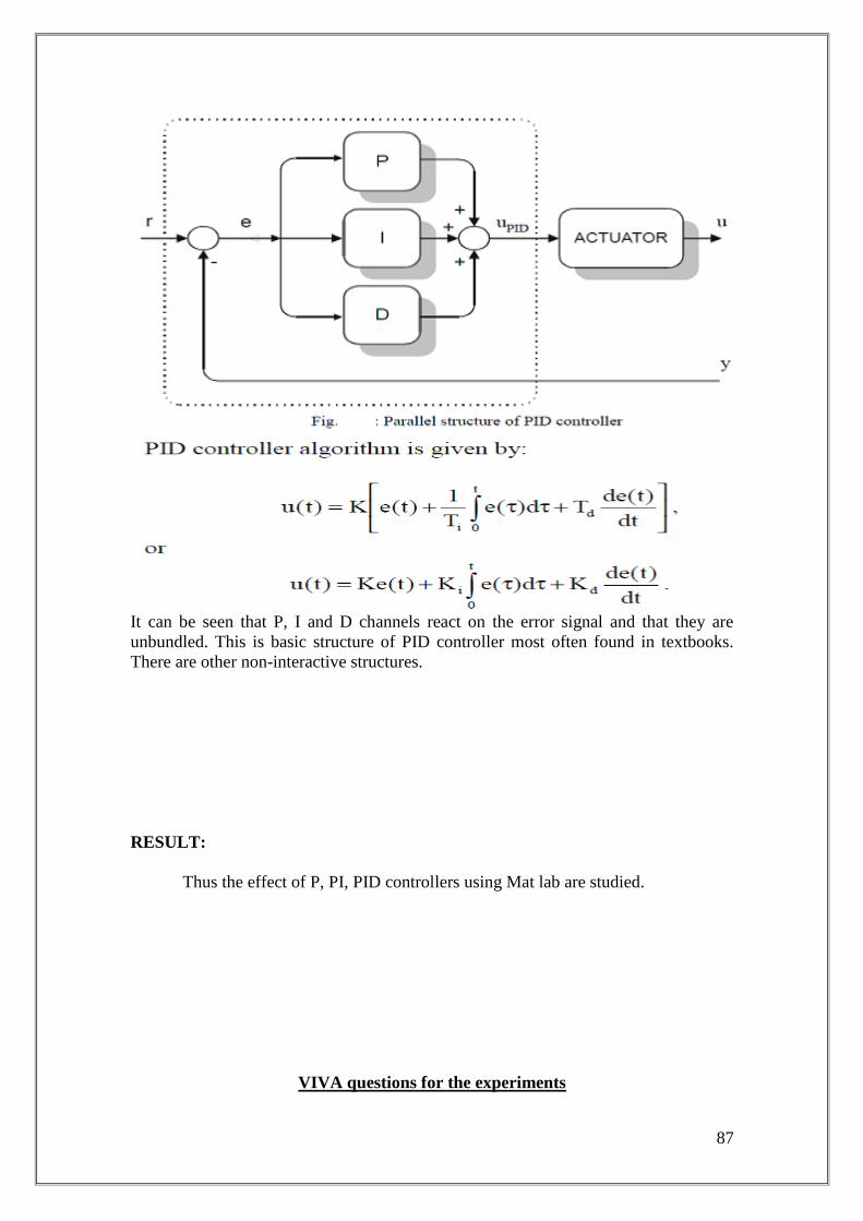
87
It can be seen that P, I and D channels react on the error signal and that they are
unbundled. This is basic structure of PID controller most often found in textbooks.
There are other non-interactive structures.
RESULT:
Thus the effect of P, PI, PID controllers using Mat lab are studied.
VIVA questions for the experiments

88
OPEN CIRCUIT CHARACTERISTICS OF SELF EXCITED
DC SHUNT GENERATOR
VIVA QUESTIONS:
1. Define critical field resistance and critical speed.
2. State the conditions to be satisfied by a DC shunt generator to build-up voltage.
3. What is residual flux and what happens to the generator induces EMF when
residual flux is zero?
4. What is the purpose of SPST switch connected in the field circuit of the
generator?
5. Why the speed must be maintained constant throughout the experiment?
LOAD TEST ON SELF EXCITED DC SHUNT GENERATOR
VIVA QUESTIONS:
1. What is a prime mover?
2. Why the speed of generator should be maintained constant during the experiment?
3. Why does the terminal voltage fall as the load on the generator is increased?
4. What is armature reaction and what are its effects on the performance of DC
generator?
OPEN CIRCUIT CHARACTERISTICS OF A SEPARATELY
EXCITED DC SHUNT GENERATOR
VIVA QUESTIONS:
1. Define critical field resistance and critical speed.
2. State the conditions to be satisfied by a DC shunt generator to build-up voltage.
3. What is residual flux and what happens to the generator induces EMF when
residual flux is zero?
4. What is the purpose of SPST switch connected in the field circuit of the
generator?
5. Why the speed must be maintained constant throughout the experiment?

89
LOAD CHARACTERISTICS ON SEPARATELY EXCITED DC SHUNT
GENERATOR
VIVA QUESTIONS:
1. What is a prime mover?
2. Why the speed of generator should be maintained constant during the experiment?
3. Why does the terminal voltage fall as the load on the generator is increased?
4. What is armature reaction and what are its effects on the performance of DC
generator?
LOAD TEST ON DC SHUNT MOTOR
VIVA QUESTIONS:
1. What is the need for a starter?
2. Name the different types of starters for DC motors.
3. Why a DC shunt motor is called a constant Speed motor?
4. State few applications of DC shunt motor.
5. What is the role of commutator in a DC motor.
6. What is the effect of armature reaction on the performance of DC motor?
7. What happen when the field circuit gets opened when a DC shunt motor is running?
8. How to reverse the direction of rotation of DC shunt motor?
SPEED CONTROL OF DC SHUNT MOTOR
VIVA QUESTIONS:
1. Which method of speed control is used for controlling the speed of the motor above its
rated speed? Give reason.
2. Which method of speed control is used for controlling the speed of the motor below its
rated speed? Give reason.
3. Explain the reasons for the shape of the graphs obtained.
4. State any method to control the speed of a D.C series motor?
SWINBURNE'S TEST
VIVA QUESTIONS:
1. What are the advantages of predetermination techniques?
2. Can the efficiency of a DC series motor be predetermined by Swinburne's test?
3. The efficiency of a generator is always more than the efficiency of motor at all load
conditions - Justify.
4. Enumerate the various losses in a DC machine.

90
LOAD TEST ON A SINGLE PHASE TRANSFORMER
VIVA QUESTIONS:
1. Define Regulation of a Transformer.
2. What is the effect of load p.f on regulation of Transformer?
3. What is the condition for maximum efficiency?
4. Determine the percentage load at which maximum efficiency occurred for the given
single-phase transformer?
5. What is the effect of change in frequency on the efficiency of the transformer?
O.C AND S.C TESTS ON A SINGLE PHASE TRANSFORMER
VIVA QUESTIONS:
1. Why O.C test is conducted on the L.V side and S.C test on the H.V side?
2. Define regulation in a transformer.
3. Why the regulation graph is not passing through the origin?
4. State the condition for maximum efficiency?
5. What is the regulation of an Ideal transformer?
6. At what fraction of full load does the efficiency of the given transformer is maximum?
PREDETERMINATION OF REGULATION BY EMFAND MMF METHOD
VIVA QUESTIONS:
1. Define regulation.
2. What is meant by pessimistic method?
3. Which method is called as optimistic method?
4. What are the advantages of EMF and MMF method?
5. Name some other methods used to predetermine the regulation.
LOAD TEST ON SQUIRREL CAGE INDUCTION MOTOR
VIVA QUESTIONS: 1. What is squirrel cage induction motor?
2. What is Skewing?
3. What is cogging?
4. What is crawling?
5. What is the no load current of an induction motor?
6. Distinguish between rotating transformer and static transformer?
7. Define slip.
NO LOAD AND BLOCKED ROTOR TEST ON THREE PHASE INDUCTION
MOTOR
VIVA QUESTIONS:
1. How will you measure three phase power using two watt meters?

91
2. What is the necessity to have starter for three phase induction motor?
3. How mechanical load is represented in the equivalent circuit of induction motor?
4. Define synchronous speed.
5. Why induction motors cannot run at synchronous speed?
STUDY OF D.C MOTOR STARTERS
VIVA QUESTIONS:
1. Differentiate two point and three point starter
2. What is the need for starter in electrical technology?
3. Differentiate four point and three point starter
4. What are the types of starter?
5. What are the protective devices used in starters?
STUDY OF INDUCTION MOTOR STARTERS
VIVA QUESTIONS:
1. Differentiate star – delta and auto transformer starter
2. What is the need for starter in electrical technology?
3. Differentiate auto transformer and DOL starter
4. What are the types of AC starters?
5. What are the protective devices used in starters?
DIGITAL SIMULATION OF LINEAR SYSTEMS
VIVA QUESTIONS:
1) Define linear system.
2) What is impulse signal?
3) What is MIMO?
4) What is time invariant system?
5) What is step signal?
STABILITY ANALYSIS OF LINEAR SYSTEM
VIVA QUESTIONS:
1) What is root locus?
2) What is bode plot?
3) What is Nyquist plot?
4) What is phase margin?
5) What is gain margin?
DESIGN AND IMPLEMENTATION OF COMPENSATORS
VIVA QUESTIONS:

92
1. What is compensation?
2. What is compensator?
3. When lag/lead/lag-lead compensators are employed?
4. What are the types of compensator?
5. Differentiate lag and lead compensators?
TRANSFER FUNCTION OF SEPERATELY EXCITED DC SHUNT
GENERATOR
VIVA QUESTIONS
1. What is the need for transfer function of a system?
2. What are the types of transfer function?
3. Define feedback.
4. Mention few applications of Separately Excited DC generator.
5. What are the basic elements used for modeling mechanical rotational system?
TRANSFER FUNCTION OF ARMATURE CONTROLLED DC SHUNT MOTOR
VIVA QUESTIONS
1. What are the draw backs of transfer function and advantages of transfer function?
2. What are the types of transfer function?
3. Define transfer function.
4. Mention few applications of Separately Excited DC generator.
5. What are the basic elements used for modeling electrical system?
TRANSFER FUNCTION OF FIELD CONTROLLED DC SHUNT MOTOR
VIVA QUESTIONS
1. What is the need for transfer function of a system?
2. Mention few applications of DC motor.
3. Differentiate open loop and closed loop system
4. Write transfer function for field control DC motor
5. Define Mechanical time constant
6. Define Electrical time constant.