chemical service valve the standard for performance · chemical service valve the standard for...
TRANSCRIPT
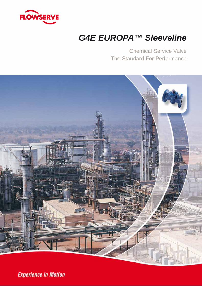
G4E EUROPA™ SleevelineChemical Service Valve
The Standard For Performance
2
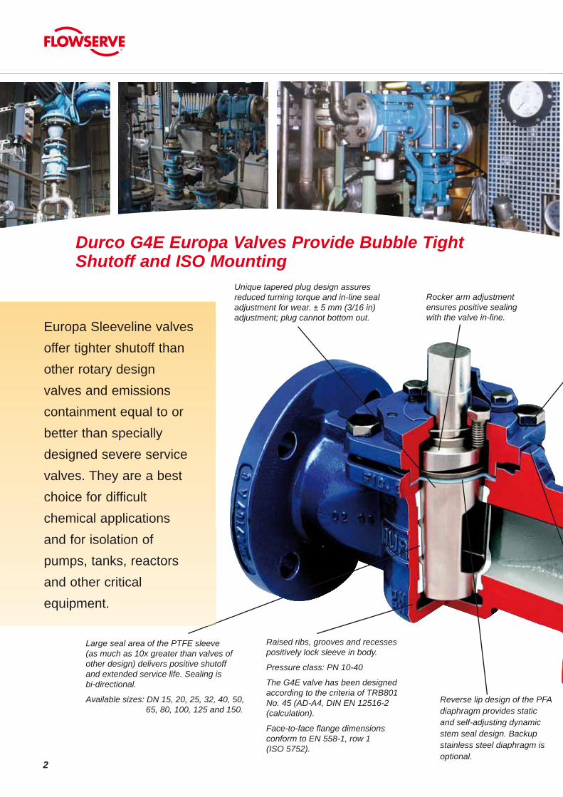
Large seal area of the PTFE sleeve(as much as 10x greater than valves ofother design) delivers positive shutoffand extended service life. Sealing isbi-directional.
Available sizes: DN 15, 20, 25, 32, 40, 50, 65, 80, 100, 125 and 150.
Raised ribs, grooves and recessespositively lock sleeve in body.
Pressure class: PN 10-40
The G4E valve has been designedaccording to the criteria of TRB801No. 45 (AD-A4, DIN EN 12516-2 (calculation).
Face-to-face flange dimensionsconform to EN 558-1, row 1(ISO 5752).
Reverse lip design of the PFA diaphragm provides static and self-adjusting dynamic stem seal design. Backup stainless steel diaphragm is optional.
Durco G4E Europa Valves Provide Bubble Tight Shutoff and ISO Mounting
Unique tapered plug design assuresreduced turning torque and in-line sealadjustment for wear. ± 5 mm (3/16 in)adjustment; plug cannot bottom out.
Rocker arm adjustment ensures positive sealing with the valve in-line.
Europa Sleeveline valvesoffer tighter shutoff thanother rotary designvalves and emissions containment equal to or better than specially designed severe service valves. They are a best choice for difficult chemical applications and for isolation of pumps, tanks, reactors and other critical equipment.

3
Static SealPFA diaphragm wedges against stem with an interference fit to seal against leakage to atmosphere or air leakage into valve on vacuum service.
Dynamic SealReverse lip diaphragm provides self-energizing dynamic stem seal where pressure activates the reverse lip to seal against the stem.
Positive stem sealA PFA diaphragm with reverse lip design provides both static and self-adjusting dynamic steam sealing. This serves as a secondary atmospheric seal to the primary plug/sleeve seal. The stem seal is not normally exposed to full line pressure.
Positive in-line plug adjustment
The unique design of the tapered plug allows a bubble tight, adjustable seal. The plug can be pushed deeper into the sleeve by two adjuster fasteners. The rocker arm gives one plane contact and resultant force down the centerline of the plug. Uniform adjustment of the two fasteners is not necessary.
Line sealingThe interference fit of the tapered plug with the PTFE sleeve serves as the sealing surface. The sleeve totally surrounds plug ports and seals the circumference of the plug, top and bottom. There are no cavities to fill up with product, and the seal area is larger than in ball valves. Sealing is both upstream and downstream. • Seal is totally independent of line pressure. • There is no metal to metal contact. • Valve remains free-turning throughout its life and never requires lubrication. • Seal is adjustable. • Wiping action between sleeve and plug provides for good slurry handling.
In-Line And Thru-Line Seal Adjustability
DIN/ISO 5211 mounting pad facilitates actuation.
Rugged, heavy-duty body may be specified in corrosion resistant stainless steels, nickel base and light reactive alloys.

4
G4EB Marathon™Valves Deliver High Cycle, Positive Stem Sealing Durability
®Viton and Kalrez are registered trademarks of the DuPont Company.®Hastelloy is a registered trademark of Haynes International.
Unique stem-sealing designThe Marathon valve can be used with confidence in chemical processing applications where tight shutoff and emissions containment are priority requirements. As a bonus, its very design assures long life, high cycle performance.
Viton O-ringsA pair of Viton® O-rings prevents stem leakage while containing line pressure. They also protect the thrust collar against attack from atmospheric corrosion. PTFE back-up rings firmly lock the Viton O-rings in the stem grooves. Optional Kalrez® O-rings are available for special services.
G4EB Marathon ValveViton O-Rings & Welded Metal Diaphragm Stem SealsSleeve & Diaphragm cut in four places
Passing the testIn a remarkable test, lab technicians defeated the PTFE sleeve and PFA diaphragm, the G4EB’s primary and secondary seals, by cutting both of them in four places. After 160,000 cycles, the G4EB emitted less than 10 parts per million of helium and showed no visible signs of stem wear.
New welded diaphragmThe integral thrust collar/alloy diaphragm is welded together for another line of defense against leakage to the atmosphere. The underside of the metal bellows-like diaphragm acts as an expansion joint by allowing the PFA diaphragm to adjust to plug movement and pressure changes.
The Hastelloy® C diaphragm provides an impermeable barrier to chlorine as well as many other services.
The conclusionG4EB Marathon valve fugitive emission containment is often equal to more expensive valves designed specifically as severe or toxic service valves.

5
G4EZ Fire Sealed Valves
Fire Sealed Sleevelinevalves – both G4EZ andG4EBZ models – incorporatespecial Grafoil® packingrings at the stem andGrafoil® gaskets at the topcap that reduce atmosphericleakage to a negligibleamount should fire destroythe PTFE sleeve anddiaphragm. A metaldiaphragm keeps the Grafoil® packing in place if the top seal is destroyed.
Durco firesealed valves have been successfully used on refinery applications such as:• Isomerization • Gas plant• Blending • Sulfur plant• Light ends • Crude desalting
Packing (Grafoil®)Diaphragm (Stainless Steel or Monel®)Diaphragm (PFA)Gasket (Grafoil)
Durco Sleeveline valves have been fire tested in accordance with the procedures set forth in API 607 Third Edition. They surpassed the external sealingrequirements of Section 4, Paragraph 4.2, “Performance Requirements.”
G4Z fire sealed valves have been temperature cycled to 204°C (400°F)*. They have provided performance superior to any other soft-seated valves available for temperature cycling applications.
Chlorine ValvesThe Durco G4E Chlorine valve is built in accordance with the recommendations of the U.S.
Chlorine Institute. This valve is manufactured with a cast carbon steel body and a vented Monel plug for dry chlorine service. It is cleaned, dried and
packaged for delivery.
Vented plug design is also recommended for
other cold liquids such as anhydrous HCL.
® Grafoil is registered trademark of Union Carbide Corporation.
* 232°C (450°F) with optional Duriron II sleeve.

6
Technical Data for Durco G4E Valves
Specially trimmed controlvalves reduce noise, cavitation and flashing whileimproving flow and pres-sure performance. Unique,self-cleaning design pre-vents particulate build-upand clogging.
Durco V-port alloy control valves are available in DN 25 through DN 150 sizes with full open Kv values of 3 through 400. They are available in a wide range of materials to satisfy your flow control needs.
Automax® automation equipmentAutomax Inc., a wholly owned sub-sidiary of Flowserve Corporation, is a specialist in complete automation systems. Automax markets a broad line of rack and pinion, heavy-duty and electric actuators. In addition, Automax offers engineered special control cir-cuits, solenoid valves, limit switches, positioners and actuator mounting kits.
G4E is readily actuated with Automax’s SuperNova™ rack and pinion actuator and Apex 5000™ positioner with Pharos®
visual position indicator.
7
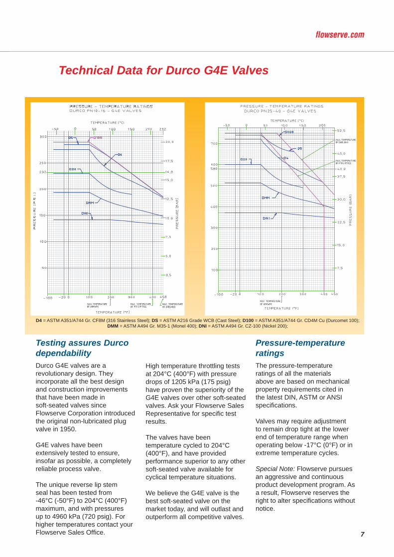
Testing assures Durco dependabilityDurco G4E valves are a revolutionary design. They incorporate all the best design and construction improvements that have been made in soft-seated valves since Flowserve Corporation introduced the original non-lubricated plug valve in 1950.
G4E valves have been extensively tested to ensure, insofar as possible, a completely reliable process valve.
The unique reverse lip stem seal has been tested from -46°C (-50°F) to 204°C (400°F) maximum, and with pressures up to 4960 kPa (720 psig). For higher temperatures contact your Flowserve Sales Office.
High temperature throttling tests at 204°C (400°F) with pressure drops of 1205 kPa (175 psig) have proven the superiority of the G4E valves over other soft-seated valves. Ask your Flowserve Sales Representative for specific test results.
The valves have been temperature cycled to 204°C (400°F), and have provided performance superior to any other soft-seated valve available for cyclical temperature situations.
We believe the G4E valve is the best soft-seated valve on the market today, and will outlast and outperform all competitive valves.
Pressure-temperature ratingsThe pressure-temperature ratings of all the materials above are based on mechanical property requirements cited in the latest DIN, ASTM or ANSI specifications.
Valves may require adjustment to remain drop tight at the lower end of temperature range when operating below -17°C (0°F) or in extreme temperature cycles.
Special Note: Flowserve pursues an aggressive and continuous product development program. As a result, Flowserve reserves the right to alter specifications without notice.
Technical Data for Durco G4E Valves
D4 = ASTM A351/A744 Gr. CF8M (316 Stainless Steel); DS = ASTM A216 Grade WCB (Cast Steel); D100 = ASTM A351/A744 Gr. CD4M Cu (Durcomet 100); DMM = ASTM A494 Gr. M35-1 (Monel 400); DNI = ASTM A494 Gr. CZ-100 (Nickel 200);

8
Technical Data for Durco G4E Valves
Manual valve turning torque*The turning torque of a PTFE sleevedplug valve is determined by two primaryfactors: setting of the plug to hold linepressure; and operating conditions(temperature, corrosion deposits,frequency of operation, etc.). All G4Evalves 150 mm and smaller are airtested at ambient temperature. The gasclosure test is in agreement with ANSIB16.34, 1988 for both the Class 150 andClass 300 valves. The average turningtorques for new valves are shown in thetable below.
0 10 20 30 40 50 60 70 80 90 100
100
90
80
70
60
50
40
30
20
10
0
Flow CharacteristicsTOTAL CHARACTERISTIC CURVE
FOR STANDARD DURCO G4E VALVE
DE
GR
EE
S O
PE
N
PER CENT OF FULL OPEN FLOW
V-PortSize Kv Cv
DN 15 - -
DN 20 - -
DN 25 3,5 / 6,9 / 26 4,1 / 8 / 30,2
DN 40 26 30,2
DN 50 46,5 54,0
DN 80 105 122,0
DN 100 162 188,3
DN 150 318 369,6
Full PortSize Kv Cv
DN 15 6,4 7,4
DN 20 16,8 19,5
DN 25 42 49
DN 40 71,8 83
DN 50 131,9 153
DN 80 276,9 322
DN 100 477,2 555
DN 150 821,2 954
Valve Standards Applicable To G4E21Specification Title
ISO 5752 (1982) Table 6-Long
Face to FaceDimensions
DIN 2501 (1971) DIN 3230 PART 3
Flange Dia., FlangeDrilling, Raised Face Dia., Etc.
DIN 2543 (1977) DIN 2545 (1977)
Flange Thickness, Raised Face Height,Etc.
ANSI B16.34 (1988)DIN 3840 (1982)
Valve Body Wall Thickness
DIN/ISO 5211.1DIN/ISO 5211.2 (1993)
Actuator Mounting Flange
Turning Torque / Sizing Torque – Nm (Ft-Lbs)Valve Size Sizing Torque for selection of actuators
Nm (Ft-Lbs)DN 15 34 (25)DN 20 34 (25)DN 25 38 (28)DN 32 38 (28)DN 40 56 (41)DN 50 95 (70)DN 65 133 (98)DN 80 133 (98)DN 100 271 (200)DN 125 271 (200)DN 150 678 (500)

9
G4E Valves are available in Materials as listed below "Materials Selection Chart"
Parts and Materials ListItem No. Description Material of Construction No.
Req.1 Body * 12 Plug * 13 Top Cap 1.4408/CF8M or Ductile Cast iron 14 Top Cap Fastener 1.4301 (B8-M S.S.) 45 Sleeve PTFE*** 16 Diaphragm PFA 1
6a Diaphragm 1.4301 S.S. (optional) 111 G4E Thrust Collar Durcoment 100 ** 112 Ajuster Durcoment 100** 113 Adjuster Fastener 1.4301 (B8-M S.S.) 217 Grounding Spring 301 S.S. 119 Stop Collar Cadmium Plated Carbon Steel 120 Stop Collar Retainer 302 S.S. 122 Wrench Ductile Iron 125 Stop Fastener 1.4301 (B8-M S.S.) 226 Stop 304 S.S. 1
Materials Selection Chart7043 = 0.7043/GGG40.3, Ref. ASTM A-395DINI = Ductile Cast Iron Nickel Plated (Plug Only)0619 = 1.0619/GSC-25, Ref. ASTM A-216, WCBDSNI = Cast Steel Nickel Plated (Plug Only 75 mm (3 in) & larger)
D2 = ASTM A351/A744 Gr. CF8 (304 S.S.)D2L = ASTM A351/A744 Gr. CF3 (304L S.S.)
4408 = 1.4408/G-X6 CrNiMo 18.10, Ref. ASTM A744, CF8MD4L = ASTM A351/A744 Gr. CF3M (316L S.S.)DV = Durcomet 5 (Durco’s High Silicon Stainless Steel)CD = ASTM A351/A744 Gr. CD4M Cu (Durcomet 100)
D20 = ASTM A351/A744 Gr. CN-7M (Durimet 20)CK3M = ASTM A351/A744 Gr. CK-3MCuN (254 SMO)1
DIN = ASTM A494 Gr. CY-40 (Inconel 600)2
DM = ASTM A494 Gr. M35-2 (Monel 400)2 DMM = ASTM A494 Gr. M35-1 (Monel 400)2
DNI = ASTM A494 Gr. CZ-100 (Nickel 200)DV2 = ASTM A494 Gr. N-7M (Chlorimet 2)DV3 = ASTM A494 Gr. CW-6M (Chlorimet 3)
Ti = ASTM B367 Gr. C-3 (Titanium)Zr = ASTM B752 Gr. 702C (Zirconium)
Zr5 = ASTM B752 Gr. 705C (Zirconium)
* Body (Item No. 1) and Plug (Item No. 2) available in the following cast materials: 0.7043, 1.0619, 1.4408, Durcomet 100, Durimet 20, Chlorimet 2 and 3, Nickel, Monel, Inconel, Titanium and Zirconium.** Durcomet 100 is a high alloy stainless steel, CD-4M Cu.***Other materials available on request.
1. Registered trademark of Avesta AB2. Registered trademark of the International Nickel Company, Inc.
6a* Backup stainless steel diaghragm is optional.

10
Flowserve Material
Specifications and Properties
Composition
Flowserve Corporation has devoted more than 90 years to the development of alloys and the production of equipment to provide long, trouble-free life when handling severe corrosives. Flowserve, valves, pipe, fittings, and various accessory castings are among the equipment engineered and produced by Flowserve Corporation in various nickel-base alloys, iron-base alloys, and reactive alloys.Corrosion charts for these alloys are available to provide assistance and reference in selection of alloy for specific service conditions.
Durco CompositionDesignation Cr Ni Mo Cu Si Mn C Fe Co
Ductile Iron 2.75 max 3.0 min Bal
Carbon Steel 0.50 max 0.5 max 0.20 max 0.30 max 0.60 max 1.00 max 0.30 max Bal
17-4PH 15.5-17.5 3.0-5.0 3.0-5.0 1.0 max 1.0 max 0.07 max Bal
Durco CF-8M 18.0-21.0 9.0-12.0 2.0-3.0 2.00 max 1.50 max 0.08 max Bal
Durcomet 100 24.5-26.5 4.75-6.00 1.75-2.25 2.75-3.25 1.00 max 1.00 max 0.04 max Bal
Durimet 20 19.0-22.0 27.5-30.5 2.0-3.0 3.0-4.0 1.50 max 1.50 max 0.07 max Bal
Durcomet 5 20.0-22.0 15.0-17.0 4.0-6.0 1.50 max .025 max Bal
Durco CK-3M 19.5-20.5 17.5-19.5 6.0-7.0 0.5-1.0 1.00 max 1.2 max. .025 max Bal
Durco CY-40 14.0-17.0 Bal 3.00 max 1.50 max 0.40 max 11.00 max
Durco M-35 Bal 26.0-33.0 1.25 max 1.50 max 0.35 max 3.50 max
Nickel CZ-100 95.0 min 1.25 max 2.00 max 1.50 max 1.00 max 3.00 max
Chlorimet 2 1.00 max Bal 30.0-33.0 1.00 max 1.00 max 0.07 max 3.00 max
Chlorimet 3 17.0-20.0 Bal 17.0-20.0 1.00 max 1.00 max 0.07 max 3.00 max
Duriron 0.50 max 0.50 max 0.50 max 14.20-14.75 1.50 max 0.70-1.10 Bal
Durichlor 51M 3.25-5.00 0.40-0.60 0.50 max 14.20-14.75 1.50 max 0.75-1.15 Bal
Superchlor 77 4.00-4.50 3.00-3.30 0.12 max. 15.50-16.00 1.00 max 0.80-0.95 Bal
Stellite 6 27.0-31.0 3.0 max 1.5 max 1.5 max 1.0 max 0.9-1.4 3.0 max Bal
Durco DC-8 Proprietary Cobalt Base Alloy Bal
Titanium N, 0.05 max; H, 0.015 max; O, 0.40 max 0.10 max 0.25 max
Titanium-Pd N, 0.05 max; H, 0.015 max; O, 0.40 max; Pd, 0.12 min 0.10 max 0.25 max
Zirconium N, 0.03 max; H, 0.005 max; O, 0.25 max; Hf, 4.5 max 0.10 max 0.30 max
Zirconium 5 N, 0.03 max; H, 0.005 max; O, 0.30 max; Hf, 4.5 max; Cb, 2.0-3.0 0.10 max 0.30 max
DurcoDesignation
DurcoSymbol
ACIDesig-nation
Equivalent-WroughtDesignation
ASTMSpecifications* DIN (WN)
Mechanical PropertiesTypicalBrinell
HardnessTensile
Strengthmin, psi
YieldPoint
min, psi
Elon-gationmin, %in 2"
Ductile Iron DCI None None A395 1693 (0.7043) 60,000 40,000 18 160Carbon Steel DS None Carbon Steel A216, Gr. WCB 17245 (1.0619) 70,000 36,000 22 15017-4PH 17-4 None 17-4PH A564, Type 630 – 145,000 125,000 13 330Durco CF-8M D4 CF-8M 316 A744, Gr. CF-8M 17445 (1.4408) 70,000 30,000 30 154Durcomet 100 CD4M CD-4MCu Ferralium 255 A995, Gr. 1B SEW410 (1.4463) 100,000 70,000 16 224Durimet 20 D20 CN-7M Alloy 20 A744, Gr. CN-7M (1.4500) 62,000 25,000 35 133Durcomet 5 DV None None None – 90,000 40,000 30 175Durco CK-3M CK-3M CK-3MCuN 254SMO A744, Gr. CK-3MCuN (1.4529) 80,000 38,000 35 195Durco CY-40 DINC CY-40 Inconel 600 A494, Gr. CY-40 17742 (2.4816) 70,000 28,000 30 147Durco M-35 DMM M-35-1 Monel 400 A494, Gr. M-35-1 17130 (2.4365) 65,000 25,000 25 130Nickel CZ-100 DNI CZ-100 Nickel 200 A494, Gr. CZ-100 17730 (2.4170) 50,000 18,000 10 118Chlorimet 2 DC2 N-7M Hastelloy B-2 A494, Gr. N-7M (2.4882) 76,000 40,000 20 200Chlorimet 3 DC3 CW-6M Hastelloy C-276 A494, Gr. CW-6M (2.4883) 72,000 40,000 25 200Duriron D None None A518, Gr. 1 – 930# (A) – – 520Durichlor 51 D51M None None A518, Gr. 2 – 930# (A) – – 520Superchlor 77 SD77 None None None – 1600# (A) – – 520Stellite 6 F6 None Stellite 6 None – 115,000 96,000 3 400Durco DC-8 DC8 None None None – – – – 300Titanium Ti None Titanium B367, Gr. C-3 17850 (3.7031) 65,000 55,000 12(B) 200Titanium-Pd Ti-Pd None Titanium-Pd B367, Gr. C-8A 17850 (3.7032) 65,000 55,000 12(B) 200Zirconium Zr None Zirconium702 B752, Gr. 702C – 55,000 40,000 12(B) 190Zirconium 5 Zr5 None Zirconium705 B752, Gr. 705C – 70,000 40,000 12(B) 190
* Whenever an ASTM specification is cited, the Durco alloy will conform to the chemical and mechanical requirements of the latest edition of the specification. (A) Minimum transverse strength. (B) Minimum percent elongation in 1".

11
G4E Valve Dimensions
Metric Units
ValveSize
Drilling Drilling DrillingA
BC D
E FPN 10-40 PN 10-16 PN25-40 PN PN PN PN PN PN PN PN PN
No. Size B.C. No. Size B.C. No. Size B.C. 10-40 10-16 25-40 10-40 10-16 25-40 10-40 10-16 25-4015 4 14 65 130 95 81 2 16 4550 4 14 75 150 105 81 2 18 5825 4 14 85 160 115 94 2 18 6832 4 18 100 180 140 94 2 18 7840 4 18 110 200 150 106 3 18 8850 4 18 125 230 165 121 3 20 10265 4 18 145 8 18 145 290 185 185 152 3 18 22 122 12280 8 18 160 310 200 152 3 24 138100 8 18 180 8 22 190 350 220 235 194 3 20 24 158 162125 8 18 210 8 26 220 400 250 270 194 3 22 26 188 188150 8 22 240 8 26 250 480 285 300 247 3 22 28 212 218
ValveSize GØ H J K M N
PR S T
W1 W2 W3 Area of Weights - kgISO Std. Std. Opt. Port PN PN PNPad Wrench Gear T-
Handle Sq. Cm. 10-40 10-16 25-4015 13.61/13.49 11.10/10.97 18 121 F05 48 130 152 350 1.59 3.250 13.61/13.49 11.10/10.97 18 121 F05 48 130 152 350 1.59 3.925 19.99/19.86 16.66/16.54 22 122 F05 58 140 178 510 5.1 6.032 19.99/19.86 16.66/16.54 22 122 F05 58 140 178 510 5.1 7.040 19.99/19.86 16.66/16.54 24 140 F05 67 140 229 510 7.8 9.350 27.31/27.18 22.23/22.10 25 160 F07 79 145 305 610 13.0 11.665 27.31/27.18 22.23/22.10 30 190 F07 106 145 457 610 30.0 16.0 18.080 27.31/27.18 22.23/22.10 30 190 F07 106 145 457 610 30.0 21.2
100 42.85/42.60 36.09/35.97 40 213 229 305 F10 133 76 150 762 224 710 48.0 30.4 35.3125 42.85/42.60 36.09/35.97 40 213 305 F10 133 76 224 48.0 45.0 55.0150 47.63/47.37 36.09/35.97 41 263 305 F12 183 76 224 104.0 66.9 73.7
English Units
ValveSize
Drilling Drilling DrillingA
BC D
E FPN 10-40 PN 10-16 PN25-40 PN PN PN PN PN PN PN PN PN
No. Size B.C. No. Size B.C. No. Size B.C. 10-40 10-16 25-40 10-40 10-16 25-40 10-40 10-16 25-40½ 4 9⁄16 29⁄16 51⁄8 3¾ 33⁄16 1⁄16 5⁄8 1¾¾ 4 6⁄16 215⁄16 515⁄16 41⁄8 33⁄16 1⁄16 11⁄16 2¼1 4 9⁄16 33⁄8 65⁄16 4½ 311⁄16 1⁄16 11⁄16 211⁄16
1¼ 4 11⁄16 315⁄16 71⁄16 5½ 311⁄16 1⁄16 11⁄16 31⁄161½ 4 11⁄16 45⁄16 77⁄8 515⁄16 43⁄16 1⁄8 11⁄16 37⁄162 4 11⁄16 415⁄16 91⁄16 6½ 4¾ 1⁄8 ¾ 4
2½ 4 11⁄16 511⁄16 8 11⁄16 511⁄16 117⁄16 7¼ 7¼ 6 1⁄8 11⁄16 7⁄8 47⁄8 413⁄163 8 11⁄16 65⁄16 123⁄16 77⁄8 6 1⁄8 15⁄16 57⁄164 8 11⁄16 71⁄16 8 7⁄8 7½ 13¾ 811⁄16 9¼ 75⁄8 1⁄8 ¾ 15⁄16 6¼ 63⁄85 8 11⁄16 8¼ 8 1 811⁄16 15¾ 97⁄8 105⁄8 75⁄8 1⁄8 7⁄8 1 73⁄8 73⁄86 8 7⁄8 97⁄16 8 1 97⁄8 187⁄8 11¼ 1113⁄16 9¾ 1⁄8 7⁄8 11⁄8 83⁄8 83⁄8
ValveSize GØ H J K M N
PR S T
W1 W2 W3 Area of Weights - kgISO Std. Std. Opt. Port PN PN PNPad Wrench Gear T-
Handle Sq. Cm. 10-40 10-16 25-40½ 17⁄32 7⁄16 23⁄32 4¾ F05 17⁄8 51⁄8 6 13¾ ¼ 7¾ 17⁄32 7⁄16 23⁄32 4¾ F05 17⁄8 51⁄8 6 13¾ ¼ 91 25⁄32 21⁄32 7⁄8 4¾ F05 25⁄16 5½ 7 20 13⁄16 13
1¼ 25⁄32 21⁄32 7⁄8 4¾ F05 25⁄16 5½ 7 20 13⁄16 161½ 25⁄32 21⁄32 1 5½ F05 25⁄8 5½ 9 20 1¼ 212 15⁄64 7⁄8 13⁄16 65⁄16 F07 31⁄8 511⁄16 12 24 2 26
2½ 15⁄64 7⁄8 13⁄16 7½ F07 43⁄16 511⁄16 18 24 45⁄8 35 403 15⁄64 7⁄8 13⁄16 7½ F07 43⁄16 511⁄16 18 24 45⁄8 474 111⁄16 127⁄64 19⁄16 83⁄8 9 12 F10 5¼ 3 57⁄8 30 813⁄16 28 73⁄8 67 785 111⁄16 127⁄64 19⁄16 83⁄8 12 F10 5¼ 3 813⁄16 73⁄8 99 1216 17⁄8 127⁄64 15⁄8 103⁄8 12 F12 73⁄16 3 813⁄16 161⁄8 148 163
All dimensions are approximate and for illustration purposes only. For exact dimensions request certified dimensional prints.

Due to continuous development of our product range, we reserve the right to alter the dimensions and information contained in this leaflet as required.Information given in this leaflet is made in good faith and based upon specific testing but does not, however, constitute a guarantee
Germany
Flowserve Ahaus GmbHvon-Braun-Straße 19aD-48683 Ahaus, GermanyTelephone: +49 (0) 2561 686 100Telefax: +49 (0) 2561 686 200
For more information about Flowserve Corporation,visit www.flowserve.com
FCD DVENBR0003-01 Printed in Germany. (Replaces V-23)
To find your local Flowserve representative: