chemical bonding and molecular structure … class 11 chemistry... · chemical bonding and...
TRANSCRIPT
96 C:\ChemistryXI\Unit-4\Unit-4(5)-Lay-4(reprint).pmd Reprint 27.7.6
96 CHEMISTRY
96
Scientists are constantly discovering new compounds, orderlyarranging the facts about them, trying to explain with theexisting knowledge, organising to modify the earlier views orevolve theories for explaining the newly observed facts.
UNIT 4
After studying this Unit, you will be
able to
• understand KÖssel-Lewisapproach to chemical bonding;
• explain the octet rule and itslimitations, draw Lewisstructures of simple molecules;
• explain the formation of differenttypes of bonds;
• describe the VSEPR theory andpredict the geometry of simplemolecules;
• explain the valence bondapproach for the formation ofcovalent bonds;
• predict the directional propertiesof covalent bonds;
• explain the different types ofhybridisation involving s, p andd orbitals and draw shapes ofsimple covalent molecules;
• describe the molecular orbitaltheory of homonuclear diatomicmolecules;
• explain the concept of hydrogenbond.
CHEMICAL BONDING ANDMOLECULAR STRUCTURE
Matter is made up of one or different type of elements.Under normal conditions no other element exists as anindependent atom in nature, except noble gases. However,a group of atoms is found to exist together as one specieshaving characteristic properties. Such a group of atoms iscalled a molecule. Obviously there must be some forcewhich holds these constituent atoms together in themolecules. The attractive force which holds variousconstituents (atoms, ions, etc.) together in differentchemical species is called a chemical bond. Since theformation of chemical compounds takes place as a resultof combination of atoms of various elements in differentways, it raises many questions. Why do atoms combine?Why are only certain combinations possible? Why do someatoms combine while certain others do not? Why domolecules possess definite shapes? To answer suchquestions different theories and concepts have been putforward from time to time. These are Kössel-Lewisapproach, Valence Shell Electron Pair Repulsion (VSEPR)Theory, Valence Bond (VB) Theory and Molecular Orbital(MO) Theory. The evolution of various theories of valenceand the interpretation of the nature of chemical bonds haveclosely been related to the developments in theunderstanding of the structure of atom, the electronicconiguration of elements and the periodic table. Everysystem tends to be more stable and bonding is nature’sway of lowering the energy of the system to attain stability.
www.stud
iestod
ay.co
m
97 C:\ChemistryXI\Unit-4\Unit-4(5)-Lay-4(reprint).pmd Reprint 27.7.6
97CHEMICAL BONDING AND MOLECULAR STRUCTURE
97
4.1 KÖSSEL-LEWIS APPROACH TOCHEMICAL BONDING
In order to explain the formation of chemicalbond in terms of electrons, a number ofattempts were made, but it was only in 1916when Kössel and Lewis succeededindependently in giving a satisfactoryexplanation. They were the first to providesome logical explanation of valence which wasbased on the inertness of noble gases.
Lewis pictured the atom in terms of apositively charged ‘Kernel’ (the nucleus plusthe inner electrons) and the outer shell thatcould accommodate a maximum of eightelectrons. He, further assumed that theseeight electrons occupy the corners of a cubewhich surround the ‘Kernel’. Thus the singleouter shell electron of sodium would occupyone corner of the cube, while in the case of anoble gas all the eight corners would beoccupied. This octet of electrons, representsa particularly stable electronic arrangement.Lewis postulated that atoms achieve thestable octet when they are linked bychemical bonds. In the case of sodium andchlorine, this can happen by the transfer ofan electron from sodium to chlorine therebygiving the Na+ and Cl
– ions. In the case of
other molecules like Cl2, H2, F2, etc., the bondis formed by the sharing of a pair of electronsbetween the atoms. In the process each atomattains a stable outer octet of electrons.
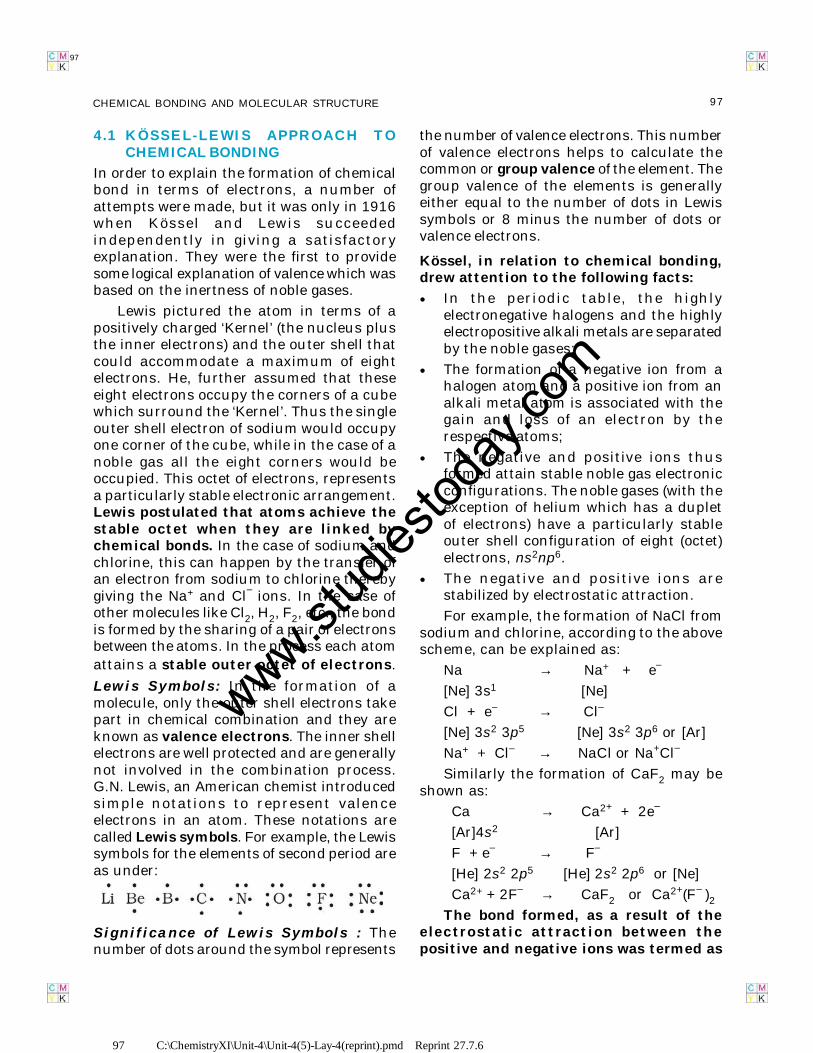
Lewis Symbols: In the formation of amolecule, only the outer shell electrons takepart in chemical combination and they areknown as valence electrons. The inner shellelectrons are well protected and are generallynot involved in the combination process.G.N. Lewis, an American chemist introducedsimple notations to represent valenceelectrons in an atom. These notations arecalled Lewis symbols. For example, the Lewissymbols for the elements of second period areas under:
Significance of Lewis Symbols : Thenumber of dots around the symbol represents
the number of valence electrons. This numberof valence electrons helps to calculate thecommon or group valence of the element. Thegroup valence of the elements is generallyeither equal to the number of dots in Lewissymbols or 8 minus the number of dots orvalence electrons.
Kössel, in relation to chemical bonding,drew attention to the following facts:
• In the periodic table, the highlyelectronegative halogens and the highlyelectropositive alkali metals are separatedby the noble gases;
• The formation of a negative ion from ahalogen atom and a positive ion from analkali metal atom is associated with thegain and loss of an electron by therespective atoms;
• The negative and positive ions thusformed attain stable noble gas electronicconfigurations. The noble gases (with theexception of helium which has a dupletof electrons) have a particularly stableouter shell configuration of eight (octet)electrons, ns2np6.
• The negative and positive ions arestabilized by electrostatic attraction.
For example, the formation of NaCl fromsodium and chlorine, according to the abovescheme, can be explained as:
Na → Na+ + e–
[Ne] 3s1 [Ne]
Cl + e– → Cl–
[Ne] 3s2 3p5 [Ne] 3s2 3p6 or [Ar]
Na+ + Cl– → NaCl or Na+Cl–
Similarly the formation of CaF2 may beshown as:
Ca → Ca2+ + 2e–
[Ar]4s2 [Ar]
F + e– → F–
[He] 2s2 2p5 [He] 2s2 2p6 or [Ne]
Ca2+ + 2F– → CaF2 or Ca2+(F– )2The bond formed, as a result of the
electrostatic attraction between thepositive and negative ions was termed as
www.stud
iestod
ay.co
m
98 C:\ChemistryXI\Unit-4\Unit-4(5)-Lay-4(reprint).pmd Reprint 27.7.6
98 CHEMISTRY
98
the electrovalent bond. The electrovalenceis thus equal to the number of unitcharge(s) on the ion. Thus, calcium isassigned a positive electrovalence of two,while chlorine a negative electrovalence ofone.
Kössel’s postulations provide the basis forthe modern concepts regarding ion-formationby electron transfer and the formation of ioniccrystalline compounds. His views have provedto be of great value in the understanding andsystematisation of the ionic compounds. Atthe same time he did recognise the fact thata large number of compounds did not fit intothese concepts.
4.1.1 Octet Rule
Kössel and Lewis in 1916 developed animportant theory of chemical combinationbetween atoms known as electronic theoryof chemical bonding. According to this,atoms can combine either by transfer ofvalence electrons from one atom to another(gaining or losing) or by sharing of valenceelectrons in order to have an octet in theirvalence shells. This is known as octet rule.
4.1.2 Covalent Bond
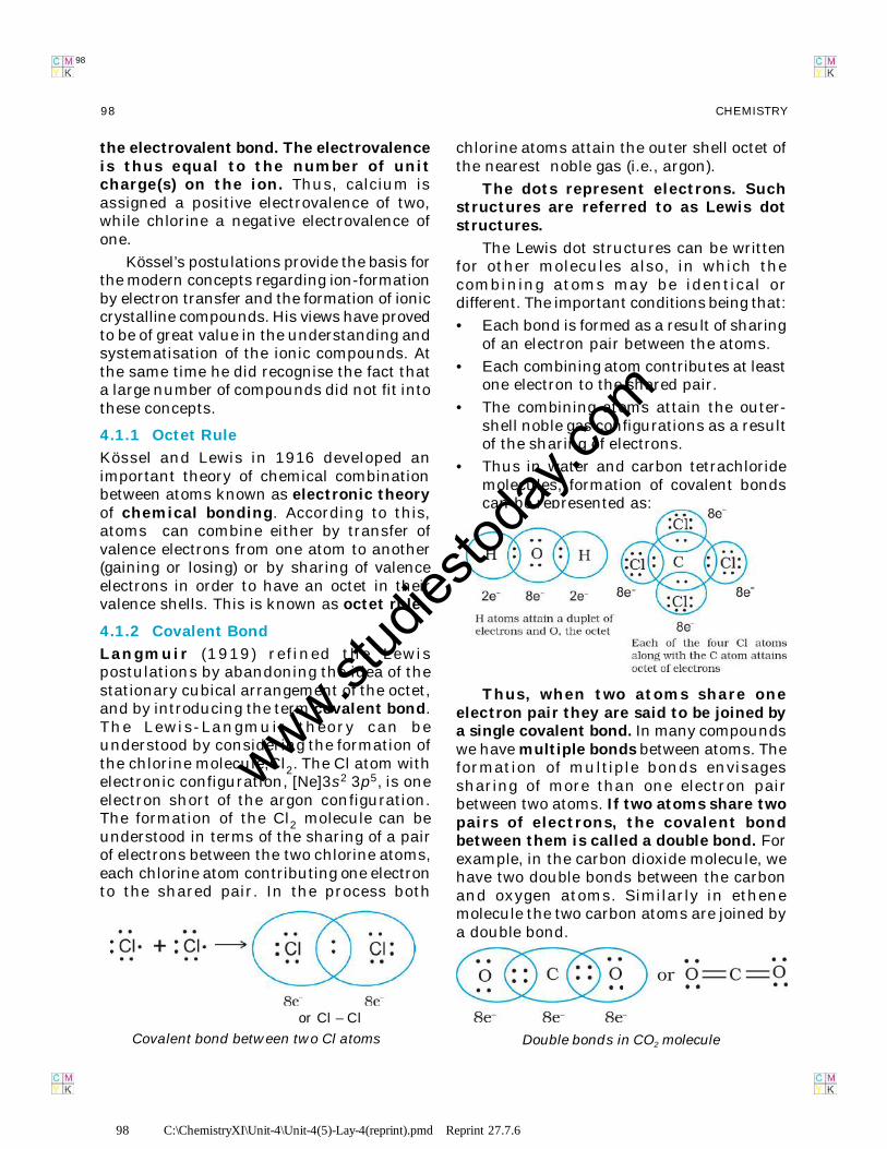
Langmuir (1919) refined the Lewispostulations by abandoning the idea of thestationary cubical arrangement of the octet,and by introducing the term covalent bond.The Lewis-Langmuir theory can beunderstood by considering the formation ofthe chlorine molecule,Cl2. The Cl atom withelectronic configuration, [Ne]3s2 3p5, is oneelectron short of the argon configuration.The formation of the Cl2 molecule can beunderstood in terms of the sharing of a pairof electrons between the two chlorine atoms,each chlorine atom contributing one electronto the shared pair. In the process both
chlorine atoms attain the outer shell octet ofthe nearest noble gas (i.e., argon).
The dots represent electrons. Suchstructures are referred to as Lewis dotstructures.
The Lewis dot structures can be writtenfor other molecules also, in which thecombining atoms may be identical ordifferent. The important conditions being that:
• Each bond is formed as a result of sharingof an electron pair between the atoms.
• Each combining atom contributes at leastone electron to the shared pair.
• The combining atoms attain the outer-shell noble gas configurations as a resultof the sharing of electrons.
• Thus in water and carbon tetrachloridemolecules, formation of covalent bondscan be represented as:
or Cl – Cl
Covalent bond between two Cl atoms
Thus, when two atoms share oneelectron pair they are said to be joined bya single covalent bond. In many compoundswe have multiple bonds between atoms. Theformation of multiple bonds envisagessharing of more than one electron pairbetween two atoms. If two atoms share twopairs of electrons, the covalent bondbetween them is called a double bond. Forexample, in the carbon dioxide molecule, wehave two double bonds between the carbonand oxygen atoms. Similarly in ethenemolecule the two carbon atoms are joined bya double bond.
Double bonds in CO2 molecule
www.stud
iestod
ay.co
m
99 C:\ChemistryXI\Unit-4\Unit-4(5)-Lay-4(reprint).pmd Reprint 27.7.6
99CHEMICAL BONDING AND MOLECULAR STRUCTURE
99
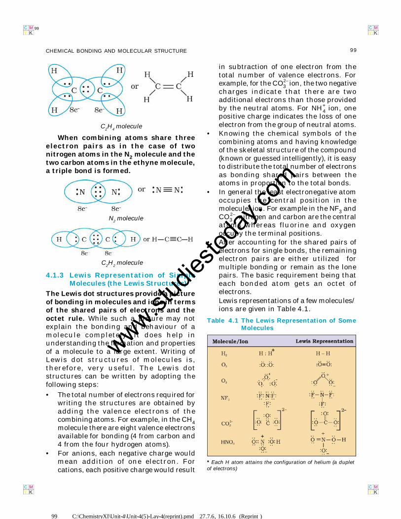
When combining atoms share threeelectron pairs as in the case of twonitrogen atoms in the N2 molecule and thetwo carbon atoms in the ethyne molecule,a triple bond is formed.
4.1.3 Lewis Representation of SimpleMolecules (the Lewis Structures)
The Lewis dot structures provide a pictureof bonding in molecules and ions in termsof the shared pairs of electrons and theoctet rule. While such a picture may notexplain the bonding and behaviour of amolecule completely, it does help inunderstanding the formation and propertiesof a molecule to a large extent. Writing ofLewis dot structures of molecules is,therefore, very useful. The Lewis dotstructures can be written by adopting thefollowing steps:
• The total number of electrons required forwriting the structures are obtained byadding the valence electrons of thecombining atoms. For example, in the CH4molecule there are eight valence electronsavailable for bonding (4 from carbon and4 from the four hydrogen atoms).
• For anions, each negative charge wouldmean addition of one electron. Forcations, each positive charge would result
in subtraction of one electron from thetotal number of valence electrons. Forexample, for the CO3
2– ion, the two negativecharges indicate that there are twoadditional electrons than those providedby the neutral atoms. For NH4
+ ion, onepositive charge indicates the loss of oneelectron from the group of neutral atoms.
• Knowing the chemical symbols of thecombining atoms and having knowledgeof the skeletal structure of the compound(known or guessed intelligently), it is easyto distribute the total number of electronsas bonding shared pairs between theatoms in proportion to the total bonds.
• In general the least electronegative atomoccupies the central position in themolecule/ion. For example in the NF3 andCO3
2–, nitrogen and carbon are the centralatoms whereas fluorine and oxygenoccupy the terminal positions.
• After accounting for the shared pairs ofelectrons for single bonds, the remainingelectron pairs are either utilized formultiple bonding or remain as the lonepairs. The basic requirement being thateach bonded atom gets an octet ofelectrons.Lewis representations of a few molecules/ions are given in Table 4.1.
Table 4.1 The Lewis Representation of SomeMolecules
* Each H atom attains the configuration of helium (a dupletof electrons)
C2H
4 molecule
N2 molecule
C2H
2 molecule
99 C:\ChemistryXI\Unit-4\Unit-4(5)-Lay-4(reprint).pmd 27.7.6, 16.10.6 (Reprint )
www.stud
iestod
ay.co
m
100 C:\ChemistryXI\Unit-4\Unit-4(5)-Lay-4(reprint).pmd Reprint 27.7.6
100 CHEMISTRY
100
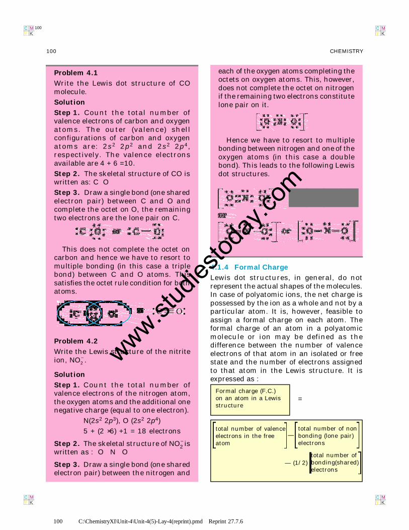
Problem 4.1
Write the Lewis dot structure of COmolecule.
Solution
Step 1. Count the total number ofvalence electrons of carbon and oxygenatoms. The outer (valence) shellconfigurations of carbon and oxygenatoms are: 2s2 2p2 and 2s2 2p4,respectively. The valence electronsavailable are 4 + 6 =10.
Step 2. The skeletal structure of CO iswritten as: C O
Step 3. Draw a single bond (one sharedelectron pair) between C and O andcomplete the octet on O, the remainingtwo electrons are the lone pair on C.
This does not complete the octet oncarbon and hence we have to resort tomultiple bonding (in this case a triplebond) between C and O atoms. Thissatisfies the octet rule condition for bothatoms.
Problem 4.2
Write the Lewis structure of the nitriteion, NO2
– .
Solution
Step 1. Count the total number ofvalence electrons of the nitrogen atom,the oxygen atoms and the additional onenegative charge (equal to one electron).
N(2s2 2p3), O (2s2 2p4)
5 + (2 × 6) +1 = 18 electrons
Step 2. The skeletal structure of NO2– is
written as : O N O
Step 3. Draw a single bond (one sharedelectron pair) between the nitrogen and
each of the oxygen atoms completing theoctets on oxygen atoms. This, however,does not complete the octet on nitrogenif the remaining two electrons constitutelone pair on it.
Hence we have to resort to multiplebonding between nitrogen and one of theoxygen atoms (in this case a doublebond). This leads to the following Lewisdot structures.
4.1.4 Formal Charge
Lewis dot structures, in general, do notrepresent the actual shapes of the molecules.In case of polyatomic ions, the net charge ispossessed by the ion as a whole and not by aparticular atom. It is, however, feasible toassign a formal charge on each atom. Theformal charge of an atom in a polyatomicmolecule or ion may be defined as thedifference between the number of valenceelectrons of that atom in an isolated or freestate and the number of electrons assignedto that atom in the Lewis structure. It isexpressed as :
Formal charge (F.C.)on an atom in a Lewisstructure
=
total number of valenceelectrons in the freeatom
—total number of nonbonding (lone pair)electrons
— (1/2)total number ofbonding(shared)electrons
www.stud
iestod
ay.co
m
101 C:\ChemistryXI\Unit-4\Unit-4(5)-Lay-4(reprint).pmd Reprint 27.7.6
101CHEMICAL BONDING AND MOLECULAR STRUCTURE
101
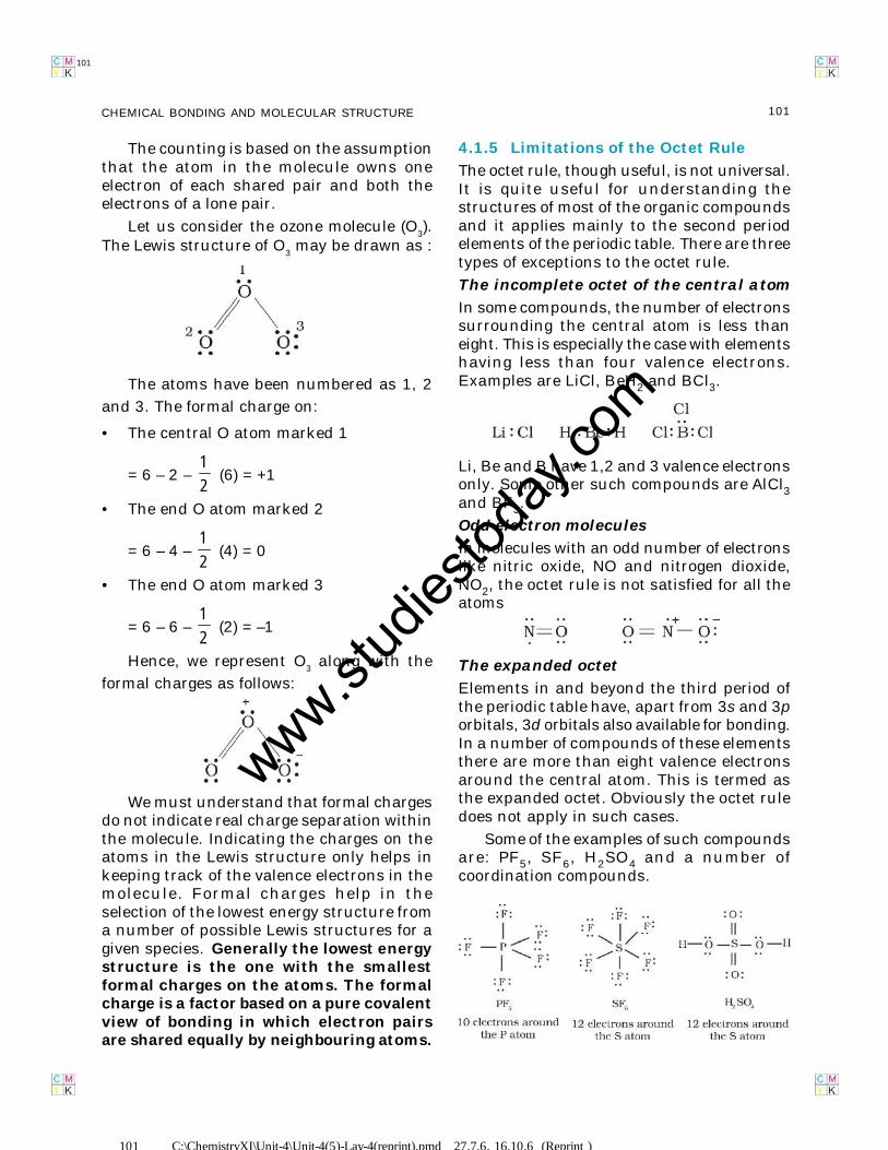
4.1.5 Limitations of the Octet Rule
The octet rule, though useful, is not universal.It is quite useful for understanding thestructures of most of the organic compoundsand it applies mainly to the second periodelements of the periodic table. There are threetypes of exceptions to the octet rule.
The incomplete octet of the central atom
In some compounds, the number of electronssurrounding the central atom is less thaneight. This is especially the case with elementshaving less than four valence electrons.Examples are LiCl, BeH2 and BCl3.
Li, Be and B have 1,2 and 3 valence electronsonly. Some other such compounds are AlCl3and BF3.
Odd-electron molecules
In molecules with an odd number of electronslike nitric oxide, NO and nitrogen dioxide,NO2, the octet rule is not satisfied for all theatoms
The expanded octet
Elements in and beyond the third period ofthe periodic table have, apart from 3s and 3porbitals, 3d orbitals also available for bonding.In a number of compounds of these elementsthere are more than eight valence electronsaround the central atom. This is termed asthe expanded octet. Obviously the octet ruledoes not apply in such cases.
Some of the examples of such compoundsare: PF5, SF6, H2SO4 and a number ofcoordination compounds.
The counting is based on the assumptionthat the atom in the molecule owns oneelectron of each shared pair and both theelectrons of a lone pair.
Let us consider the ozone molecule (O3).
The Lewis structure of O3 may be drawn as :
The atoms have been numbered as 1, 2
and 3. The formal charge on:
• The central O atom marked 1
= 6 – 2 –12
(6) = +1
• The end O atom marked 2
= 6 – 4 –12
(4) = 0
• The end O atom marked 3
= 6 – 6 –12
(2) = –1
Hence, we represent O3 along with the
formal charges as follows:
We must understand that formal chargesdo not indicate real charge separation withinthe molecule. Indicating the charges on theatoms in the Lewis structure only helps inkeeping track of the valence electrons in themolecule. Formal charges help in theselection of the lowest energy structure froma number of possible Lewis structures for agiven species. Generally the lowest energystructure is the one with the smallestformal charges on the atoms. The formalcharge is a factor based on a pure covalentview of bonding in which electron pairsare shared equally by neighbouring atoms.
101 C:\ChemistryXI\Unit-4\Unit-4(5)-Lay-4(reprint).pmd 27.7.6, 16.10.6 (Reprint )
www.stud
iestod
ay.co
m
102 C:\ChemistryXI\Unit-4\Unit-4(5)-Lay-4(reprint).pmd Reprint 27.7.6
102 CHEMISTRY
102
Interestingly, sulphur also forms manycompounds in which the octet rule is obeyed.In sulphur dichloride, the S atom has an octetof electrons around it.
Other drawbacks of the octet theory
• It is clear that octet rule is based uponthe chemical inertness of noble gases.However, some noble gases (for examplexenon and krypton) also combine withoxygen and fluorine to form a number ofcompounds like XeF
2, KrF
2, XeOF
2 etc.,
• This theory does not account for the shapeof molecules.
• It does not explain the relative stability ofthe molecules being totally silent aboutthe energy of a molecule.
4.2 IONIC OR ELECTROVALENT BOND
From the Kössel and Lewis treatment of theformation of an ionic bond, it follows that theformation of ionic compounds wouldprimarily depend upon:
• The ease of formation of the positive andnegative ions from the respective neutralatoms;
• The arrangement of the positive andnegative ions in the solid, that is, thelattice of the crystalline compound.
The formation of a positive ion involvesionization, i.e., removal of electron(s) fromthe neutral atom and that of the negative ioninvolves the addition of electron(s) to theneutral atom.
M(g) → M+(g) + e– ;Ionization enthalpy
X(g) + e– → X – (g) ;Electron gain enthalpy
M+(g) + X –(g) → MX(s)
The electron gain enthalpy, ∆egH, is theenthalpy change (Unit 3), when a gas phase atomin its ground state gains an electron. Theelectron gain process may be exothermic orendothermic. The ionization, on the other hand,is always endothermic. Electron affinity, is thenegative of the energy change accompanyingelectron gain.
Obviously ionic bonds will be formedmore easily between elements withcomparatively low ionization enthalpiesand elements with comparatively highnegative value of electron gain enthalpy.
Most ionic compounds have cationsderived from metallic elements and anionsfrom non-metall ic elements. Theammonium ion, NH4
+ (made up of two non-metallic elements) is an exception. It formsthe cation of a number of ionic compounds.
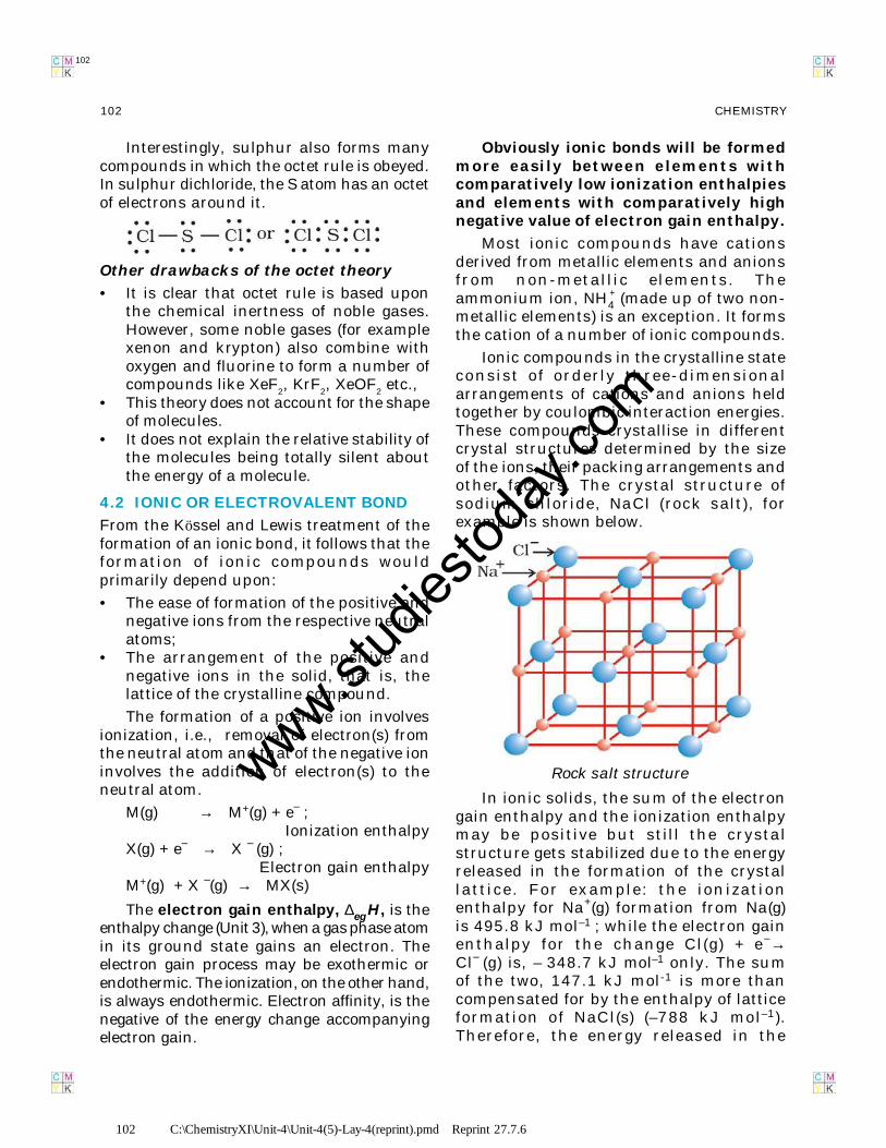
Ionic compounds in the crystalline stateconsist of orderly three-dimensionalarrangements of cations and anions heldtogether by coulombic interaction energies.These compounds crystallise in differentcrystal structures determined by the sizeof the ions, their packing arrangements andother factors. The crystal structure ofsodium chloride, NaCl (rock salt), forexample is shown below.
In ionic solids, the sum of the electrongain enthalpy and the ionization enthalpymay be positive but still the crystalstructure gets stabilized due to the energyreleased in the formation of the crystallatt ice. For example: the ionizationenthalpy for Na+(g) formation from Na(g)is 495.8 kJ mol–1 ; while the electron gainenthalpy for the change Cl(g) + e–→Cl– (g) is, – 348.7 kJ mol–1 only. The sumof the two, 147.1 kJ mol-1 is more thancompensated for by the enthalpy of latticeformation of NaCl(s) (–788 kJ mol–1).Therefore, the energy released in the
Rock salt structurewww.stud
iestod
ay.co
m
103 C:\ChemistryXI\Unit-4\Unit-4(5)-Lay-4(reprint).pmd Reprint 27.7.6
103CHEMICAL BONDING AND MOLECULAR STRUCTURE
103
processes is more than the energy absorbed.Thus a qualitative measure of thestability of an ionic compound isprovided by its enthalpy of latticeformation and not simply by achievingoctet of electrons around the ionic speciesin gaseous state.
Since lattice enthalpy plays a key rolein the formation of ionic compounds, it isimportant that we learn more about it.
4.2.1 Lattice Enthalpy
The Lattice Enthalpy of an ionic solid isdefined as the energy required tocompletely separate one mole of a solidionic compound into gaseous constituentions. For example, the lattice enthalpy of NaClis 788 kJ mol–1. This means that 788 kJ ofenergy is required to separate one mole ofsolid NaCl into one mole of Na+ (g) and onemole of Cl– (g) to an infinite distance.
This process involves both the attractiveforces between ions of opposite charges andthe repulsive forces between ions of likecharge. The solid crystal being three-dimensional; it is not possible to calculatelattice enthalpy directly from the interactionof forces of attraction and repulsion only.Factors associated with the crystal geometryhave to be included.
4.3 BOND PARAMETERS
4.3.1 Bond Length
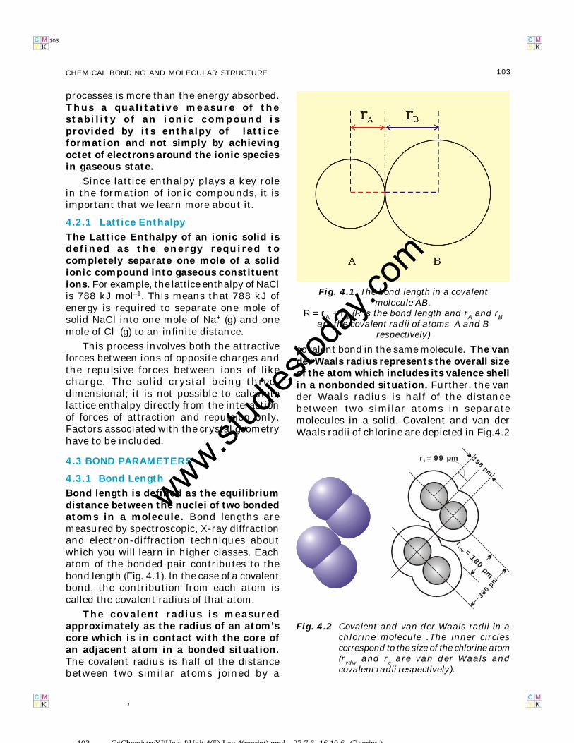
Bond length is defined as the equilibriumdistance between the nuclei of two bondedatoms in a molecule. Bond lengths aremeasured by spectroscopic, X-ray diffractionand electron-diffraction techniques aboutwhich you will learn in higher classes. Eachatom of the bonded pair contributes to thebond length (Fig. 4.1). In the case of a covalentbond, the contribution from each atom iscalled the covalent radius of that atom.
The covalent radius is measuredapproximately as the radius of an atom’score which is in contact with the core ofan adjacent atom in a bonded situation.The covalent radius is half of the distancebetween two similar atoms joined by a
,
Fig. 4.1 The bond length in a covalentmolecule AB.
R = rA + rB (R is the bond length and rA and rBare the covalent radii of atoms A and B
respectively)
covalent bond in the same molecule. The vander Waals radius represents the overall sizeof the atom which includes its valence shellin a nonbonded situation. Further, the vander Waals radius is half of the distancebetween two similar atoms in separatemolecules in a solid. Covalent and van derWaals radii of chlorine are depicted in Fig.4.2
Fig. 4.2 Covalent and van der Waals radii in achlorine molecule .The inner circlescorrespond to the size of the chlorine atom(r
vdw and r
c are van der Waals and
covalent radii respectively).
r = 99 pmc 198 pm
r=
180pm
vdw
360
pm
103 C:\ChemistryXI\Unit-4\Unit-4(5)-Lay-4(reprint).pmd 27.7.6, 16.10.6 (Reprint )
www.stud
iestod
ay.co
m
104 C:\ChemistryXI\Unit-4\Unit-4(5)-Lay-4(reprint).pmd Reprint 27.7.6
104 CHEMISTRY
104
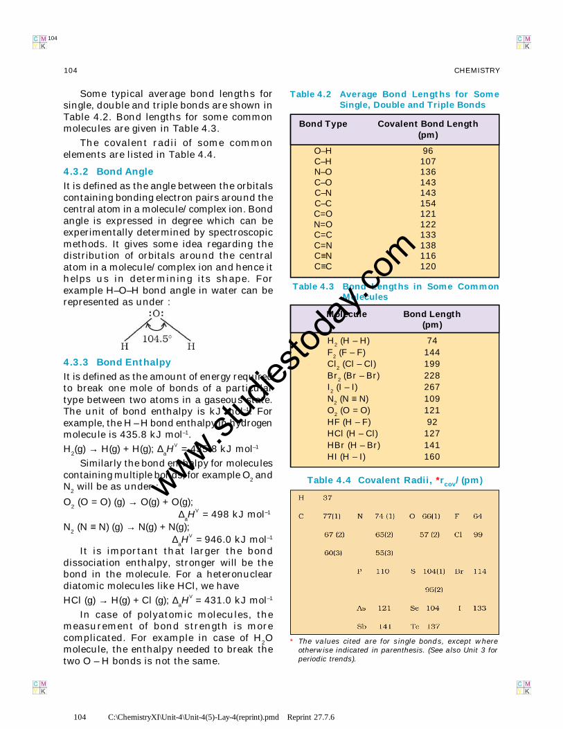
Some typical average bond lengths forsingle, double and triple bonds are shown inTable 4.2. Bond lengths for some commonmolecules are given in Table 4.3.
The covalent radii of some commonelements are listed in Table 4.4.
4.3.2 Bond Angle
It is defined as the angle between the orbitalscontaining bonding electron pairs around thecentral atom in a molecule/complex ion. Bondangle is expressed in degree which can beexperimentally determined by spectroscopicmethods. It gives some idea regarding thedistribution of orbitals around the centralatom in a molecule/complex ion and hence ithelps us in determining its shape. Forexample H–O–H bond angle in water can berepresented as under :
4.3.3 Bond Enthalpy
It is defined as the amount of energy requiredto break one mole of bonds of a particulartype between two atoms in a gaseous state.The unit of bond enthalpy is kJ mol–1. Forexample, the H – H bond enthalpy in hydrogenmolecule is 435.8 kJ mol–1.
H2(g) → H(g) + H(g); ∆
aHV = 435.8 kJ mol–1
Similarly the bond enthalpy for moleculescontaining multiple bonds, for example O
2 and
N2 will be as under :
O2 (O = O) (g) → O(g) + O(g);
∆aHV = 498 kJ mol–1
N2 (N ≡ N) (g) → N(g) + N(g);
∆aHV = 946.0 kJ mol–1
It is important that larger the bonddissociation enthalpy, stronger will be thebond in the molecule. For a heteronucleardiatomic molecules like HCl, we have
HCl (g) → H(g) + Cl (g); ∆aHV = 431.0 kJ mol–1
In case of polyatomic molecules, themeasurement of bond strength is morecomplicated. For example in case of H
2O
molecule, the enthalpy needed to break thetwo O – H bonds is not the same.
Table 4.2 Average Bond Lengths for SomeSingle, Double and Triple Bonds
Bond Type Covalent Bond Length(pm)
O–H 96C–H 107N–O 136C–O 143C–N 143C–C 154C=O 121N=O 122C=C 133C=N 138C≡N 116C≡C 120
Table 4.3 Bond Lengths in Some CommonMolecules
Molecule Bond Length(pm)
H2 (H – H) 74F2 (F – F) 144Cl2 (Cl – Cl) 199Br2 (Br – Br) 228I2 (I – I) 267N2 (N ≡ N) 109O2 (O = O) 121HF (H – F) 92HCl (H – Cl) 127HBr (H – Br) 141HI (H – I) 160
Table 4.4 Covalent Radii, *rcov/(pm)
* The values cited are for single bonds, except whereotherwise indicated in parenthesis. (See also Unit 3 forperiodic trends).
www.stud
iestod
ay.co
m
105 C:\ChemistryXI\Unit-4\Unit-4(5)-Lay-4(reprint).pmd Reprint 27.7.6
105CHEMICAL BONDING AND MOLECULAR STRUCTURE
105
H2O(g) → H(g) + OH(g); ∆
aH
1
V = 502 kJ mol–1
OH(g) → H(g) + O(g); ∆aH
2
V = 427 kJ mol–1
The difference in the ∆aHV value shows
that the second O – H bond undergoes somechange because of changed chemicalenvironment. This is the reason for somedifference in energy of the same O – H bondin different molecules like C
2H
5OH (ethanol)
and water. Therefore in polyatomic moleculesthe term mean or average bond enthalpy isused. It is obtained by dividing total bonddissociation enthalpy by the number of bondsbroken as explained below in case of watermolecule,
Average bond enthalpy =502 427
2+
= 464.5 kJ mol–1
4.3.4 Bond Order
In the Lewis description of covalent bond,the Bond Order is given by the number ofbonds between the two atoms in amolecule. The bond order, for example in H2(with a single shared electron pair), in O2(with two shared electron pairs) and in N2(with three shared electron pairs) is 1,2,3respectively. Similarly in CO (three sharedelectron pairs between C and O) the bondorder is 3. For N2, bond order is 3 and its
a∆ HV is 946 kJ mol–1; being one of thehighest for a diatomic molecule.
Isoelectronic molecules and ions haveidentical bond orders; for example, F2 andO2
2– have bond order 1. N2, CO and NO+
have bond order 3.
A general correlation useful forunderstanding the stablities of moleculesis that: with increase in bond order, bondenthalpy increases and bond lengthdecreases.
4.3.5 Resonance Structures
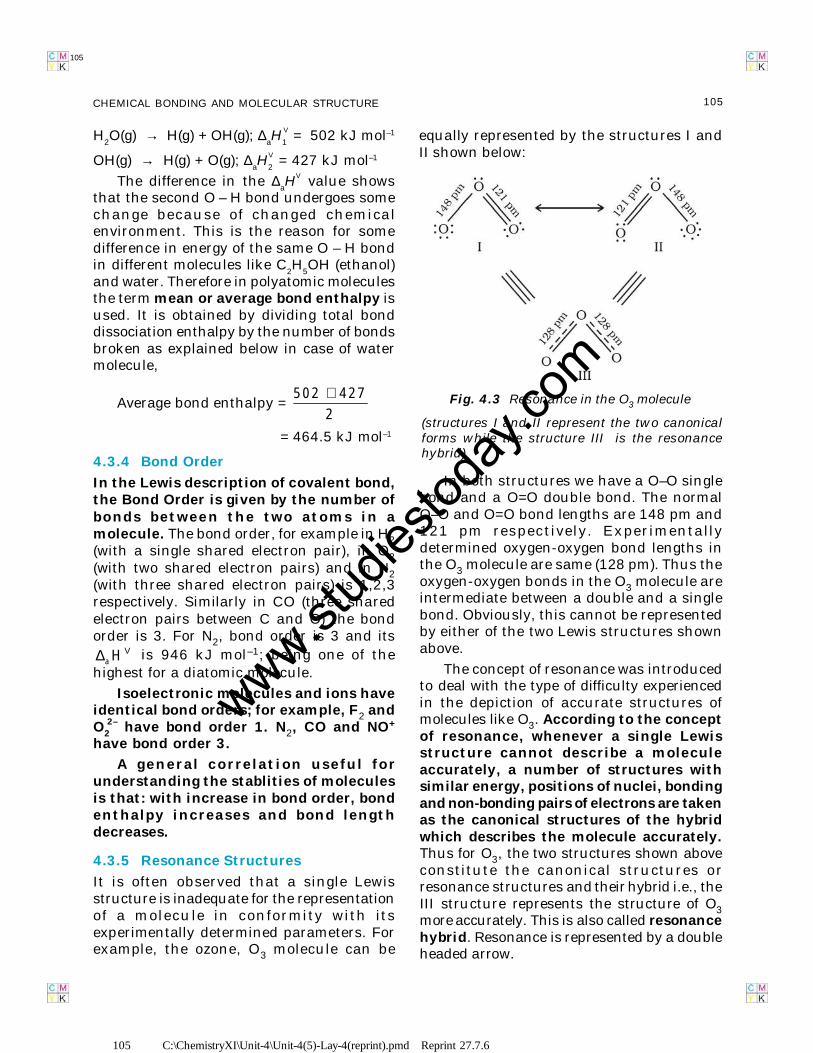
It is often observed that a single Lewisstructure is inadequate for the representationof a molecule in conformity with itsexperimentally determined parameters. Forexample, the ozone, O3 molecule can be
equally represented by the structures I andII shown below:
In both structures we have a O–O singlebond and a O=O double bond. The normalO–O and O=O bond lengths are 148 pm and121 pm respectively. Experimentallydetermined oxygen-oxygen bond lengths inthe O3 molecule are same (128 pm). Thus theoxygen-oxygen bonds in the O3 molecule areintermediate between a double and a singlebond. Obviously, this cannot be representedby either of the two Lewis structures shownabove.
The concept of resonance was introducedto deal with the type of difficulty experiencedin the depiction of accurate structures ofmolecules like O3. According to the conceptof resonance, whenever a single Lewisstructure cannot describe a moleculeaccurately, a number of structures withsimilar energy, positions of nuclei, bondingand non-bonding pairs of electrons are takenas the canonical structures of the hybridwhich describes the molecule accurately.Thus for O3, the two structures shown aboveconstitute the canonical structures orresonance structures and their hybrid i.e., theIII structure represents the structure of O3more accurately. This is also called resonancehybrid. Resonance is represented by a doubleheaded arrow.
Fig. 4.3 Resonance in the O3 molecule
(structures I and II represent the two canonicalforms while the structure III is the resonancehybrid)
www.stud
iestod
ay.co
m
106 C:\ChemistryXI\Unit-4\Unit-4(5)-Lay-4(reprint).pmd Reprint 27.7.6
106 CHEMISTRY
106
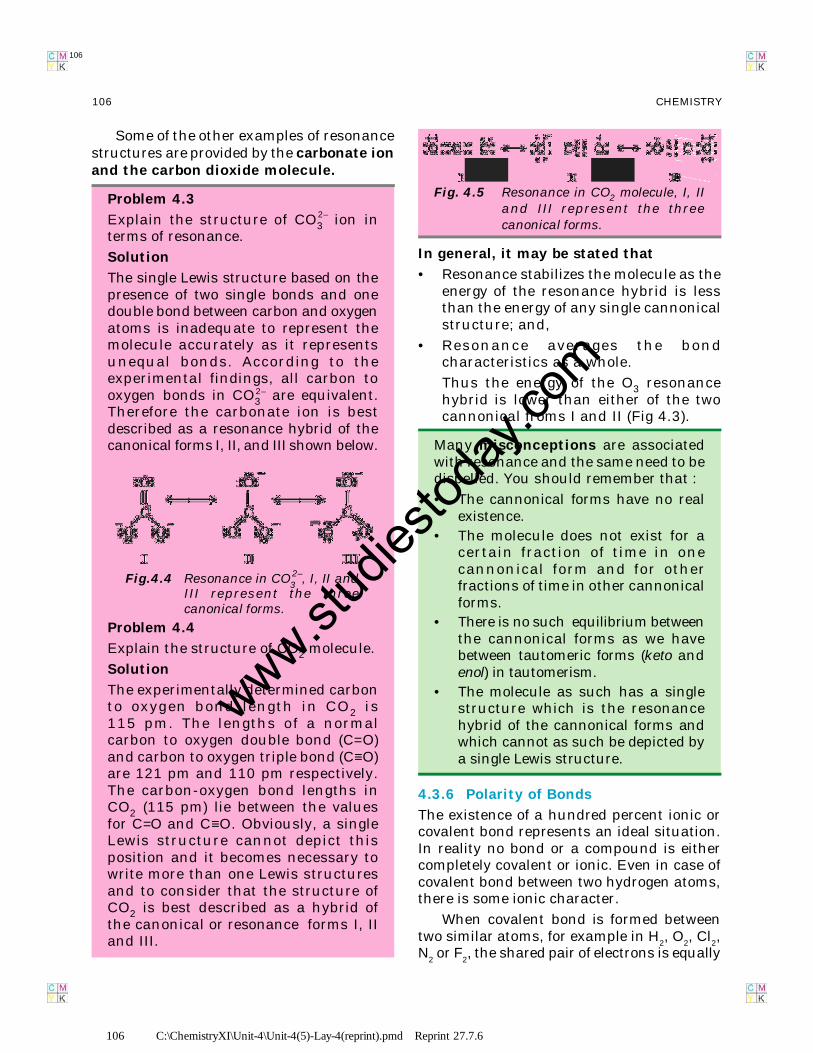
Some of the other examples of resonancestructures are provided by the carbonate ionand the carbon dioxide molecule.
Problem 4.3
Explain the structure of CO32– ion in
terms of resonance.
Solution
The single Lewis structure based on thepresence of two single bonds and onedouble bond between carbon and oxygenatoms is inadequate to represent themolecule accurately as it representsunequal bonds. According to theexperimental findings, all carbon tooxygen bonds in CO3
2– are equivalent.Therefore the carbonate ion is bestdescribed as a resonance hybrid of thecanonical forms I, II, and III shown below.
Problem 4.4
Explain the structure of CO2 molecule.
Solution
The experimentally determined carbonto oxygen bond length in CO2 is115 pm. The lengths of a normalcarbon to oxygen double bond (C=O)and carbon to oxygen triple bond (C≡O)are 121 pm and 110 pm respectively.The carbon-oxygen bond lengths inCO2 (115 pm) lie between the valuesfor C=O and C≡O. Obviously, a singleLewis structure cannot depict thisposition and it becomes necessary towrite more than one Lewis structuresand to consider that the structure ofCO2 is best described as a hybrid ofthe canonical or resonance forms I, IIand III.
In general, it may be stated that
• Resonance stabilizes the molecule as theenergy of the resonance hybrid is lessthan the energy of any single cannonicalstructure; and,
• Resonance averages the bondcharacteristics as a whole.
Thus the energy of the O3 resonancehybrid is lower than either of the twocannonical froms I and II (Fig 4.3).
Many misconceptions are associatedwith resonance and the same need to bedispelled. You should remember that :
• The cannonical forms have no realexistence.
• The molecule does not exist for acertain fraction of time in onecannonical form and for otherfractions of time in other cannonicalforms.
• There is no such equilibrium betweenthe cannonical forms as we havebetween tautomeric forms (keto andenol) in tautomerism.
• The molecule as such has a singlestructure which is the resonancehybrid of the cannonical forms andwhich cannot as such be depicted bya single Lewis structure.
4.3.6 Polarity of Bonds
The existence of a hundred percent ionic orcovalent bond represents an ideal situation.In reality no bond or a compound is eithercompletely covalent or ionic. Even in case ofcovalent bond between two hydrogen atoms,there is some ionic character.
When covalent bond is formed betweentwo similar atoms, for example in H
2, O
2, Cl
2,
N2 or F
2, the shared pair of electrons is equally
Fig.4.4 Resonance in CO32–, I, II and
III represent the threecanonical forms.
Fig. 4.5 Resonance in CO2 molecule, I, IIand III represent the threecanonical forms.
www.stud
iestod
ay.co
m
107 C:\ChemistryXI\Unit-4\Unit-4(5)-Lay-4(reprint).pmd Reprint 27.7.6
107CHEMICAL BONDING AND MOLECULAR STRUCTURE
107
attracted by the two atoms. As a resultelectron pair is situated exactly between thetwo identical nuclei. The bond so formed iscalled nonpolar covalent bond. Contrary tothis in case of a heteronuclear molecule likeHF, the shared electron pair between the twoatoms gets displaced more towards fluorinesince the electronegativity of fluorine (Unit 3)is far greater than that of hydrogen. Theresultant covalent bond is a polar covalentbond.
As a result of polarisation, the moleculepossesses the dipole moment (depictedbelow) which can be defined as the productof the magnitude of the charge and thedistance between the centres of positive andnegative charge. It is usually designated by aGreek letter ‘µ’. Mathematically, it is expressedas follows :
Dipole moment (µ) = charge (Q) × distance of separation (r)
Dipole moment is usually expressed inDebye units (D).The conversionfactor is
1 D = 3.33564 × 10⁻³⁰ C m
where C is coulomb and m is meter.
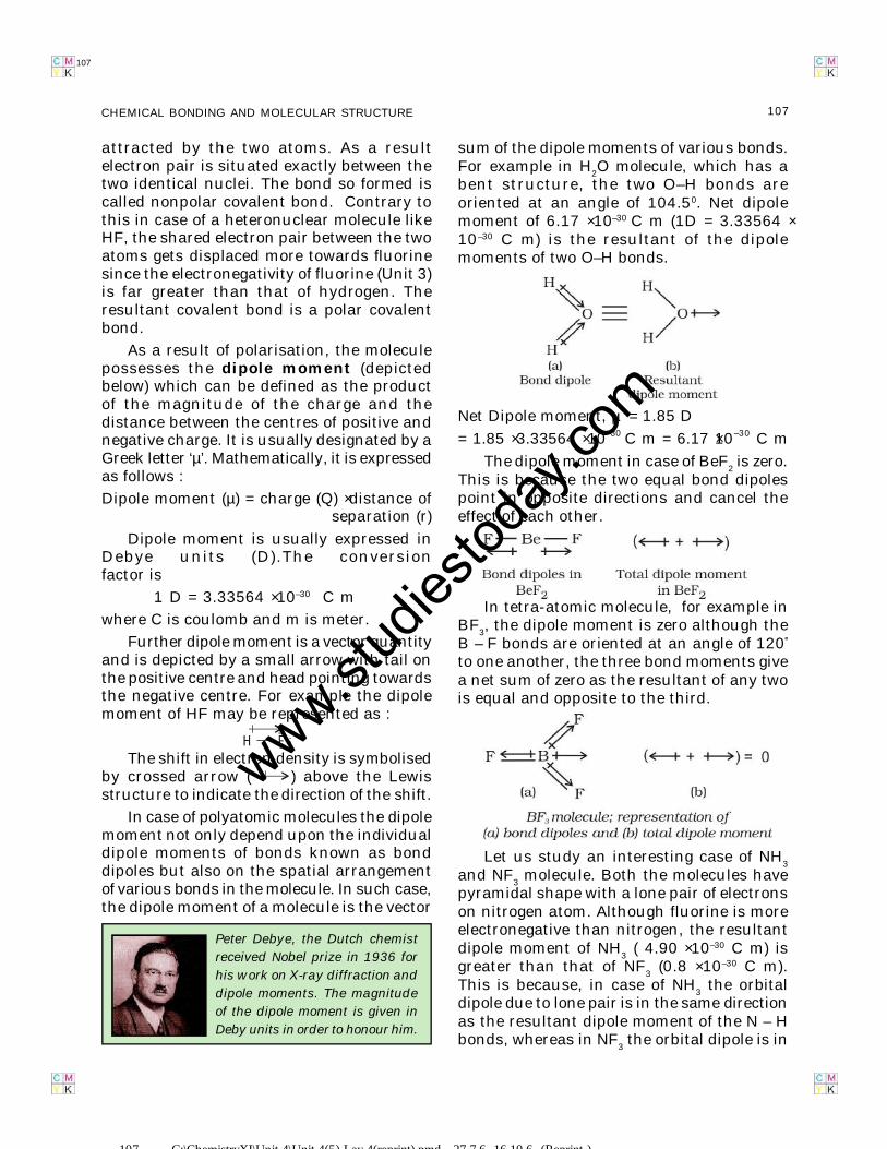
Further dipole moment is a vector quantityand is depicted by a small arrow with tail onthe positive centre and head pointing towardsthe negative centre. For example the dipolemoment of HF may be represented as :
H FThe shift in electron density is symbolised
by crossed arrow ( ) above the Lewisstructure to indicate the direction of the shift.
In case of polyatomic molecules the dipolemoment not only depend upon the individualdipole moments of bonds known as bonddipoles but also on the spatial arrangementof various bonds in the molecule. In such case,the dipole moment of a molecule is the vector
Peter Debye, the Dutch chemist
received Nobel prize in 1936 for
his work on X-ray diffraction and
dipole moments. The magnitude
of the dipole moment is given in
Deby units in order to honour him.
sum of the dipole moments of various bonds.For example in H
2O molecule, which has a
bent structure, the two O–H bonds areoriented at an angle of 104.50. Net dipolemoment of 6.17 × 10⁻³⁰ C m (1D = 3.33564 ×10⁻³⁰ C m) is the resultant of the dipolemoments of two O–H bonds.
Net Dipole moment, µ = 1.85 D
= 1.85 × 3.33564 × 10–30 C m = 6.17 ×10⁻³⁰ C m
The dipole moment in case of BeF2 is zero.
This is because the two equal bond dipolespoint in opposite directions and cancel theeffect of each other.
In tetra-atomic molecule, for example inBF
3, the dipole moment is zero although the
B – F bonds are oriented at an angle of 120°
to one another, the three bond moments givea net sum of zero as the resultant of any twois equal and opposite to the third.
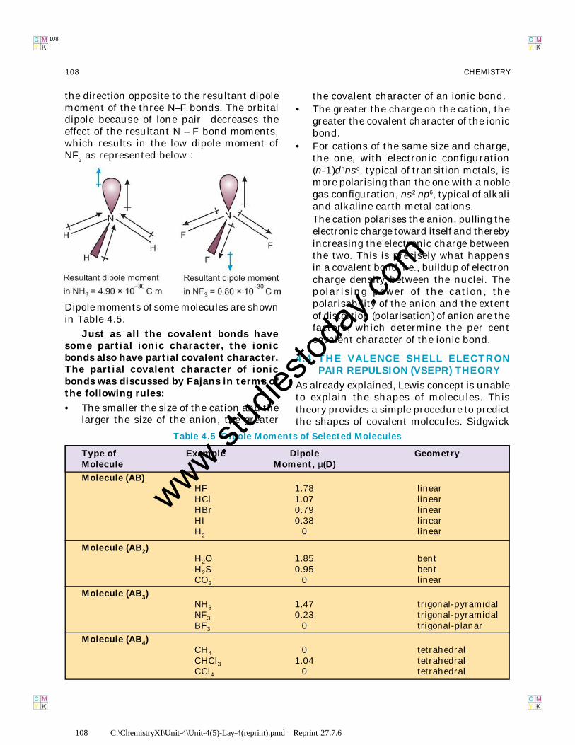
Let us study an interesting case of NH3
and NF3 molecule. Both the molecules have
pyramidal shape with a lone pair of electronson nitrogen atom. Although fluorine is moreelectronegative than nitrogen, the resultantdipole moment of NH
3 ( 4.90 × 10⁻³⁰ C m) is
greater than that of NF3 (0.8 × 10⁻³⁰ C m).
This is because, in case of NH3 the orbital
dipole due to lone pair is in the same directionas the resultant dipole moment of the N – Hbonds, whereas in NF
3 the orbital dipole is in
107 C:\ChemistryXI\Unit-4\Unit-4(5)-Lay-4(reprint).pmd 27.7.6, 16.10.6 (Reprint )
www.stud
iestod
ay.co
m
108 C:\ChemistryXI\Unit-4\Unit-4(5)-Lay-4(reprint).pmd Reprint 27.7.6
108 CHEMISTRY
108
the direction opposite to the resultant dipolemoment of the three N–F bonds. The orbitaldipole because of lone pair decreases theeffect of the resultant N – F bond moments,which results in the low dipole moment ofNF
3 as represented below :
the covalent character of an ionic bond.• The greater the charge on the cation, the
greater the covalent character of the ionicbond.
• For cations of the same size and charge,the one, with electronic configuration(n-1)dnnso, typical of transition metals, ismore polarising than the one with a noblegas configuration, ns2 np6, typical of alkaliand alkaline earth metal cations.The cation polarises the anion, pulling theelectronic charge toward itself and therebyincreasing the electronic charge betweenthe two. This is precisely what happensin a covalent bond, i.e., buildup of electroncharge density between the nuclei. Thepolarising power of the cation, thepolarisability of the anion and the extentof distortion (polarisation) of anion are thefactors, which determine the per centcovalent character of the ionic bond.
4.4 THE VALENCE SHELL ELECTRONPAIR REPULSION (VSEPR) THEORY
As already explained, Lewis concept is unableto explain the shapes of molecules. Thistheory provides a simple procedure to predictthe shapes of covalent molecules. Sidgwick
Dipole moments of some molecules are shownin Table 4.5.
Just as all the covalent bonds havesome partial ionic character, the ionicbonds also have partial covalent character.The partial covalent character of ionicbonds was discussed by Fajans in terms ofthe following rules:
• The smaller the size of the cation and thelarger the size of the anion, the greater
Type of Example Dipole GeometryMolecule Moment, µ(D)
Molecule (AB)HF 1.78 linearHCl 1.07 linearHBr 0.79 linearHI 0.38 linearH2 0 linear
Molecule (AB2)H2O 1.85 bentH2S 0.95 bentCO2 0 linear
Molecule (AB3)NH3 1.47 trigonal-pyramidalNF3 0.23 trigonal-pyramidalBF3 0 trigonal-planar
Molecule (AB4)CH4 0 tetrahedralCHCl3 1.04 tetrahedralCCl4 0 tetrahedral
Table 4.5 Dipole Moments of Selected Molecules
www.stud
iestod
ay.co
m
109 C:\ChemistryXI\Unit-4\Unit-4(5)-Lay-4(reprint).pmd Reprint 27.7.6
109CHEMICAL BONDING AND MOLECULAR STRUCTURE
109
and Powell in 1940, proposed a simple theorybased on the repulsive interactions of theelectron pairs in the valence shell of theatoms. It was further developed and redefinedby Nyholm and Gillespie (1957).
The main postulates of VSEPR theory areas follows:
• The shape of a molecule depends uponthe number of valence shell electron pairs(bonded or nonbonded) around the centralatom.
• Pairs of electrons in the valence shell repelone another since their electron clouds arenegatively charged.
• These pairs of electrons tend to occupysuch positions in space that minimiserepulsion and thus maximise distancebetween them.
• The valence shell is taken as a sphere withthe electron pairs localising on thespherical surface at maximum distancefrom one another.
• A multiple bond is treated as if it is a singleelectron pair and the two or three electronpairs of a multiple bond are treated as asingle super pair.
• Where two or more resonance structurescan represent a molecule, the VSEPRmodel is applicable to any such structure.
The repulsive interaction of electron pairsdecrease in the order:
Lone pair (lp) – Lone pair (lp) > Lone pair (lp)– Bond pair (bp) > Bond pair (bp) –Bond pair (bp)
Nyholm and Gillespie (1957) refined theVSEPR model by explaining the importantdifference between the lone pairs and bondingpairs of electrons. While the lone pairs arelocalised on the central atom, each bondedpair is shared between two atoms. As a result,the lone pair electrons in a molecule occupymore space as compared to the bonding pairsof electrons. This results in greater repulsionbetween lone pairs of electrons as comparedto the lone pair - bond pair and bond pair -bond pair repulsions. These repulsion effects
result in deviations from idealised shapes andalterations in bond angles in molecules.
For the prediction of geometrical shapesof molecules with the help of VSEPR theory,it is convenient to divide molecules into twocategories as (i) molecules in which thecentral atom has no lone pair and (ii)molecules in which the central atom hasone or more lone pairs.
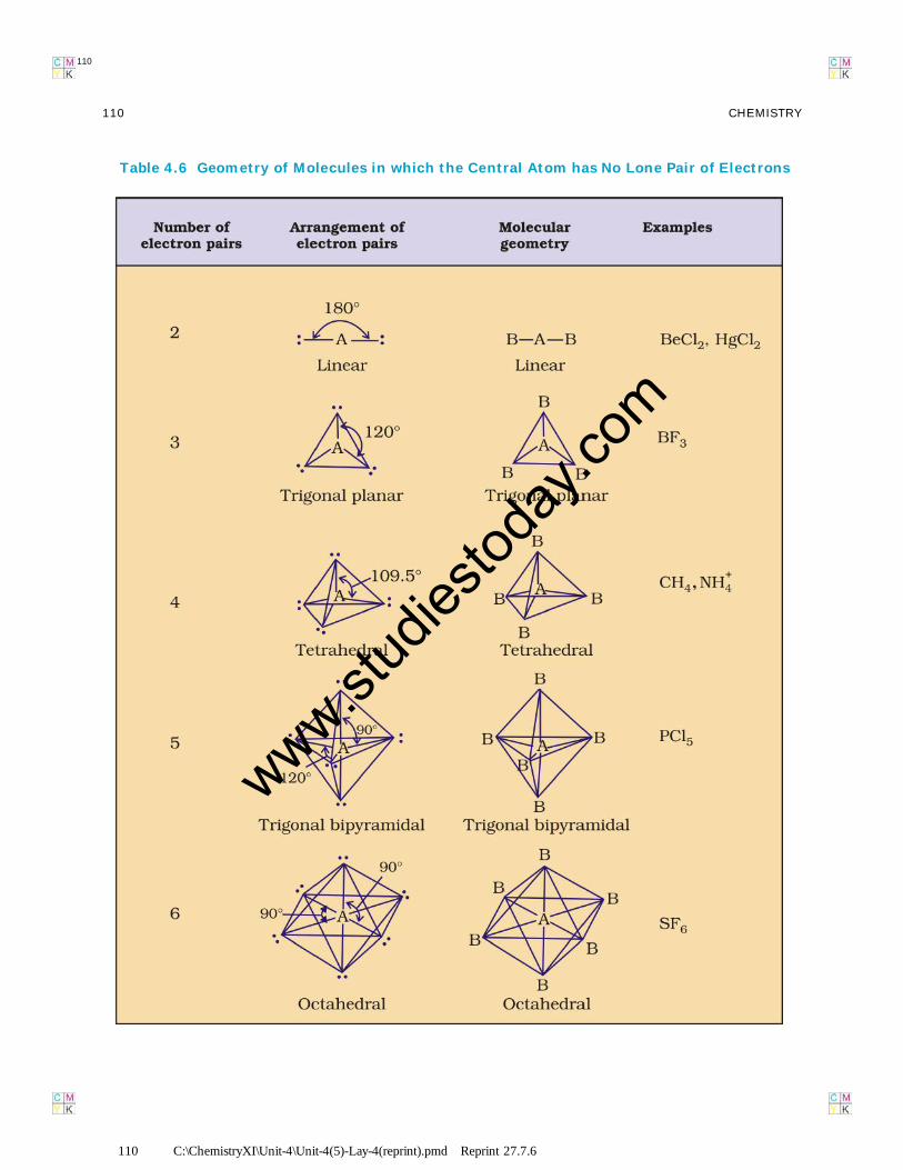
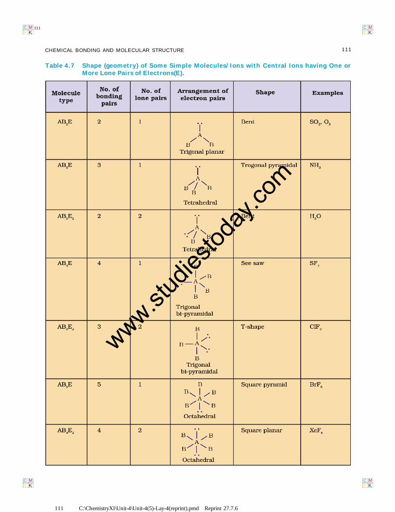
Table 4.6 (page110) shows thearrangement of electron pairs about a centralatom A (without any lone pairs) andgeometries of some molecules/ions of the typeAB. Table 4.7 (page 111) shows shapes ofsome simple molecules and ions in which thecentral atom has one or more lone pairs. Table4.8 (page 112) explains the reasons for thedistortions in the geometry of the molecule.
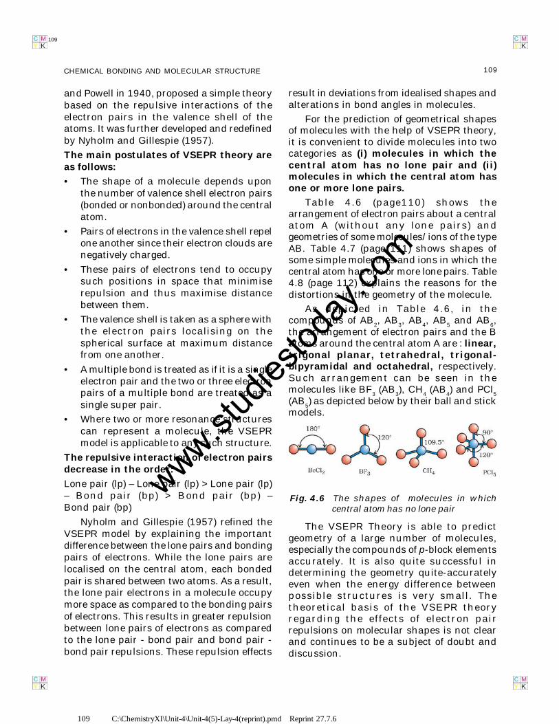
As depicted in Table 4.6, in thecompounds of AB
2, AB
3, AB
4, AB
5 and AB
6,
the arrangement of electron pairs and the Batoms around the central atom A are : linear,trigonal planar, tetrahedral, trigonal-bipyramidal and octahedral, respectively.Such arrangement can be seen in themolecules like BF
3 (AB
3), CH
4 (AB
4) and PCl
5
(AB5) as depicted below by their ball and stick
models.
The VSEPR Theory is able to predictgeometry of a large number of molecules,especially the compounds of p-block elementsaccurately. It is also quite successful indetermining the geometry quite-accuratelyeven when the energy difference betweenpossible structures is very small. Thetheoretical basis of the VSEPR theoryregarding the effects of electron pairrepulsions on molecular shapes is not clearand continues to be a subject of doubt anddiscussion.
Fig. 4.6 The shapes of molecules in whichcentral atom has no lone pair
www.stud
iestod
ay.co
m
110 C:\ChemistryXI\Unit-4\Unit-4(5)-Lay-4(reprint).pmd Reprint 27.7.6
110 CHEMISTRY
110
Table 4.6 Geometry of Molecules in which the Central Atom has No Lone Pair of Electrons
www.stud
iestod
ay.co
m
111 C:\ChemistryXI\Unit-4\Unit-4(5)-Lay-4(reprint).pmd Reprint 27.7.6
111CHEMICAL BONDING AND MOLECULAR STRUCTURE
111
Table 4.7 Shape (geometry) of Some Simple Molecules/Ions with Central Ions having One orMore Lone Pairs of Electrons(E).
www.stud
iestod
ay.co
m
112 C:\ChemistryXI\Unit-4\Unit-4(5)-Lay-4(reprint).pmd Reprint 27.7.6
112 CHEMISTRY
112
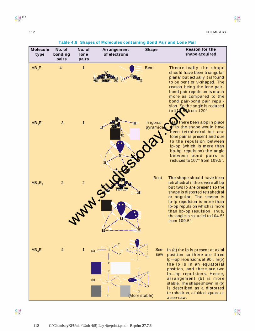
Theoretically the shapeshould have been triangularplanar but actually it is foundto be bent or v-shaped. Thereason being the lone pair-bond pair repulsion is muchmore as compared to thebond pair-bond pair repul-sion. So the angle is reducedto 119.5° from 120°.
Had there been a bp in placeof lp the shape would havebeen tetrahedral but onelone pair is present and dueto the repulsion betweenlp-bp (which is more thanbp-bp repulsion) the anglebetween bond pairs isreduced to 107° from 109.5°.
The shape should have beentetrahedral if there were all bpbut two lp are present so theshape is distorted tetrahedralor angular. The reason islp-lp repulsion is more thanlp-bp repulsion which is morethan bp-bp repulsion. Thus,the angle is reduced to 104.5°from 109.5°.
Bent
Trigonalpyramidal
Bent
AB2E 4 1
AB3E 3 1
AB2E2 2 2
In (a) the lp is present at axialposition so there are threelp—bp repulsions at 90°. In(b)the lp is in an equatorialposition, and there are twolp—bp repulsions. Hence,arrangement (b) is morestable. The shape shown in (b)is described as a distortedtetrahedron, a folded square ora see-saw.
See-saw
AB4E 4 1
(More stable)
Table 4.8 Shapes of Molecules containing Bond Pair and Lone Pair
Shape Reason for theshape acquired
Arrangementof electrons
No. oflonepairs
No. ofbonding
pairs
Moleculetype
www.stud
iestod
ay.co
m
113 C:\ChemistryXI\Unit-4\Unit-4(5)-Lay-4(reprint).pmd Reprint 27.7.6
113CHEMICAL BONDING AND MOLECULAR STRUCTURE
113
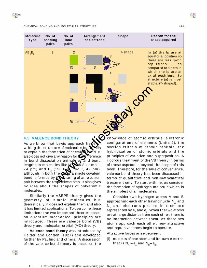
In (a) the lp are atequatorial position sothere are less lp-bprepulsions ascompared to others inwhich the lp are ataxial positions. Sostructure (a) is moststable. (T-shaped).
T-shapeAB3E2 3 2
Shape Reason for theshape acquired
Arrangementof electrons
No. oflonepairs
No. ofbonding
pairs
Moleculetype
4.5 VALENCE BOND THEORY
As we know that Lewis approach helps inwriting the structure of molecules but it failsto explain the formation of chemical bond. Italso does not give any reason for the differencein bond dissociation enthalpies and bondlengths in molecules like H
2 (435.8 kJ mol-1,
74 pm) and F2 (150.6 kJ mol-1, 42 pm),
although in both the cases a single covalentbond is formed by the sharing of an electronpair between the respective atoms. It also givesno idea about the shapes of polyatomicmolecules.
Similarly the VSEPR theory gives thegeometry of simple molecules buttheoretically, it does not explain them and alsoit has limited applications. To overcome theselimitations the two important theories basedon quantum mechanical principles areintroduced. These are valence bond (VB)theory and molecular orbital (MO) theory.
Valence bond theory was introduced byHeitler and London (1927) and developedfurther by Pauling and others. A discussionof the valence bond theory is based on the
knowledge of atomic orbitals, electronicconfigurations of elements (Units 2), theoverlap criteria of atomic orbitals, thehybridization of atomic orbitals and theprinciples of variation and superposition. Arigorous treatment of the VB theory in termsof these aspects is beyond the scope of thisbook. Therefore, for the sake of convenience,valence bond theory has been discussed interms of qualitative and non-mathematicaltreatment only. To start with, let us considerthe formation of hydrogen molecule which isthe simplest of all molecules.
Consider two hydrogen atoms A and Bapproaching each other having nuclei N
A and
NB and electrons present in them are
represented by eA and e
B. When the two atoms
are at large distance from each other, there isno interaction between them. As these twoatoms approach each other, new attractiveand repulsive forces begin to operate.
Attractive forces arise between:
(i) nucleus of one atom and its own electronthat is N
A – e
A and N
B– e
B.
www.stud
iestod
ay.co
m
114 C:\ChemistryXI\Unit-4\Unit-4(5)-Lay-4(reprint).pmd Reprint 27.7.6
114 CHEMISTRY
114
(ii) nucleus of one atom and electron of otheratom i.e., N
A– e
B, N
B– e
A.
Similarly repulsive forces arise between(i) electrons of two atoms like e
A – e
B,
(ii) nuclei of two atoms NA – N
B.
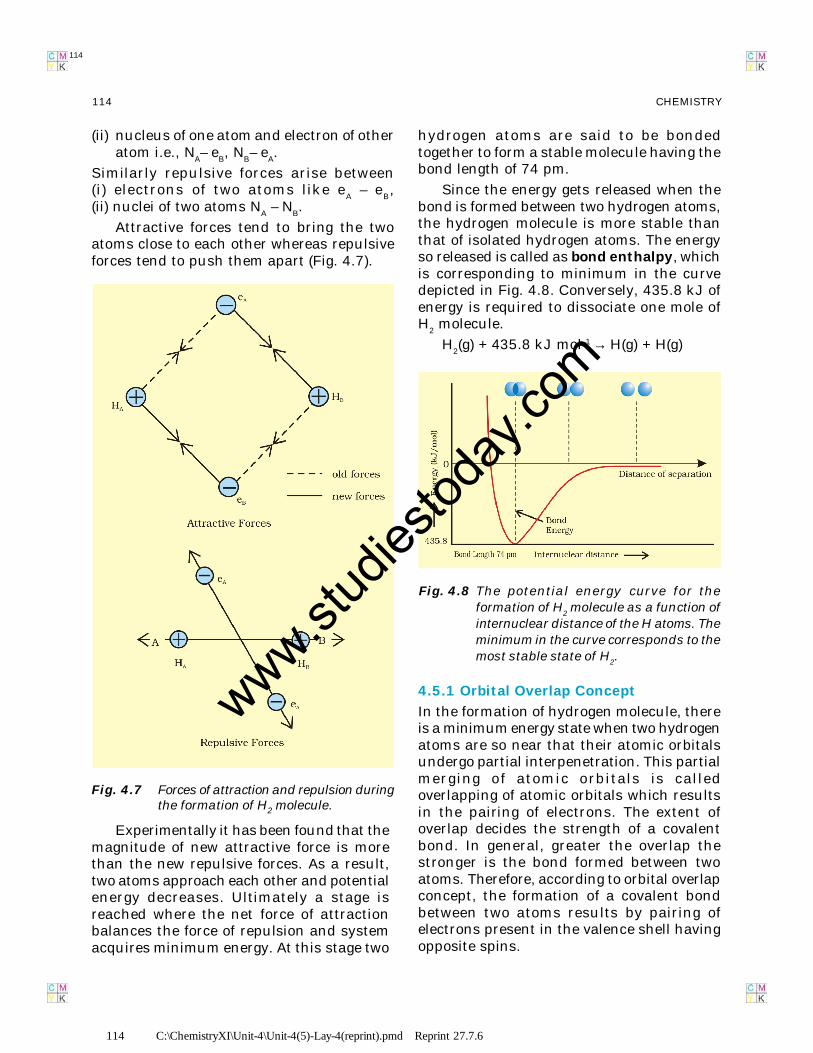
Attractive forces tend to bring the twoatoms close to each other whereas repulsiveforces tend to push them apart (Fig. 4.7).
Experimentally it has been found that themagnitude of new attractive force is morethan the new repulsive forces. As a result,two atoms approach each other and potentialenergy decreases. Ultimately a stage isreached where the net force of attractionbalances the force of repulsion and systemacquires minimum energy. At this stage two
Fig. 4.7 Forces of attraction and repulsion duringthe formation of H2 molecule.
hydrogen atoms are said to be bondedtogether to form a stable molecule having thebond length of 74 pm.
Since the energy gets released when thebond is formed between two hydrogen atoms,the hydrogen molecule is more stable thanthat of isolated hydrogen atoms. The energyso released is called as bond enthalpy, whichis corresponding to minimum in the curvedepicted in Fig. 4.8. Conversely, 435.8 kJ ofenergy is required to dissociate one mole ofH
2 molecule.
H2(g) + 435.8 kJ mol–1 → H(g) + H(g)
4.5.1 Orbital Overlap Concept
In the formation of hydrogen molecule, thereis a minimum energy state when two hydrogenatoms are so near that their atomic orbitalsundergo partial interpenetration. This partialmerging of atomic orbitals is calledoverlapping of atomic orbitals which resultsin the pairing of electrons. The extent ofoverlap decides the strength of a covalentbond. In general, greater the overlap thestronger is the bond formed between twoatoms. Therefore, according to orbital overlapconcept, the formation of a covalent bondbetween two atoms results by pairing ofelectrons present in the valence shell havingopposite spins.
Fig. 4.8 The potential energy curve for theformation of H
2 molecule as a function of
internuclear distance of the H atoms. Theminimum in the curve corresponds to themost stable state of H
2.
www.stud
iestod
ay.co
m
115 C:\ChemistryXI\Unit-4\Unit-4(5)-Lay-4(reprint).pmd Reprint 27.7.6
115CHEMICAL BONDING AND MOLECULAR STRUCTURE
115
4.5.2 Directional Properties of Bonds
As we have already seen the formation ofcovalent bond depends on the overlapping ofatomic orbitals. The molecule of hydrogen isformed due to the overlap of 1s-orbitals oftwo H atoms, when they combine with eachother.
In case of polyatomic molecules like CH4,
NH3 and H
2O, the geometry of the molecules
is also important in addition to the bondformation. For example why is it so that CH
4
molecule has tetrahedral shape and HCHbond angles are 109.5°? Why is the shape ofNH
3 molecule pyramidal ?
The valence bond theory explains theformation and directional properties of bondsin polyatomic molecules like CH
4, NH
3 and
H2O, etc. in terms of overlap and hybridisation
of atomic orbitals.
4.5.3 Overlapping of Atomic Orbitals
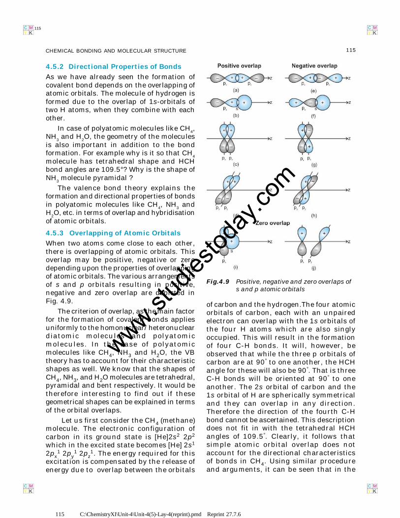
When two atoms come close to each other,there is overlapping of atomic orbitals. Thisoverlap may be positive, negative or zerodepending upon the properties of overlappingof atomic orbitals. The various arrangementsof s and p orbitals resulting in positive,negative and zero overlap are depicted inFig. 4.9.
The criterion of overlap, as the main factorfor the formation of covalent bonds appliesuniformly to the homonuclear/heteronucleardiatomic molecules and polyatomicmolecules. In the case of polyatomicmolecules like CH4, NH3 and H2O, the VBtheory has to account for their characteristicshapes as well. We know that the shapes ofCH4, NH3, and H2O molecules are tetrahedral,pyramidal and bent respectively. It would betherefore interesting to find out if thesegeometrical shapes can be explained in termsof the orbital overlaps.
Let us first consider the CH4 (methane)molecule. The electronic configuration ofcarbon in its ground state is [He]2s2 2p2
which in the excited state becomes [He] 2s1
2px1 2py
1 2pz1. The energy required for this
excitation is compensated by the release ofenergy due to overlap between the orbitals
Fig.4.9 Positive, negative and zero overlaps ofs and p atomic orbitals
of carbon and the hydrogen.The four atomicorbitals of carbon, each with an unpairedelectron can overlap with the 1s orbitals ofthe four H atoms which are also singlyoccupied. This will result in the formationof four C-H bonds. It will, however, beobserved that while the three p orbitals ofcarbon are at 90° to one another, the HCHangle for these will also be 90°. That is threeC-H bonds will be oriented at 90° to oneanother. The 2s orbital of carbon and the1s orbital of H are spherically symmetricaland they can overlap in any direction.Therefore the direction of the fourth C-Hbond cannot be ascertained. This descriptiondoes not fit in with the tetrahedral HCHangles of 109.5°. Clearly, it follows thatsimple atomic orbital overlap does notaccount for the directional characteristicsof bonds in CH4. Using similar procedureand arguments, it can be seen that in the
www.stud
iestod
ay.co
m
116 C:\ChemistryXI\Unit-4\Unit-4(5)-Lay-4(reprint).pmd Reprint 27.7.6
116 CHEMISTRY
116
case of NH3 and H2O molecules, the HNHand HOH angles should be 90°. This is indisagreement with the actual bond anglesof 107° and 104.5° in the NH3 and H2Omolecules respectively.
4.5.4 Types of Overlapping and Nature ofCovalent Bonds
The covalent bond may be classified into twotypes depending upon the types ofoverlapping:
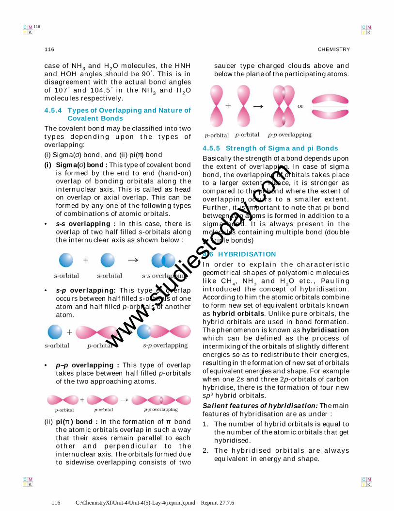
(i) Sigma(σ) bond, and (ii) pi(π) bond
(i) Sigma(σ) bond : This type of covalent bondis formed by the end to end (hand-on)overlap of bonding orbitals along theinternuclear axis. This is called as headon overlap or axial overlap. This can beformed by any one of the following typesof combinations of atomic orbitals.
• s-s overlapping : In this case, there isoverlap of two half filled s-orbitals alongthe internuclear axis as shown below :
• s-p overlapping: This type of overlapoccurs between half filled s-orbitals of oneatom and half filled p-orbitals of anotheratom.
• p–p overlapping : This type of overlaptakes place between half filled p-orbitalsof the two approaching atoms.
(ii) pi(π ) bond : In the formation of π bondthe atomic orbitals overlap in such a waythat their axes remain parallel to eachother and perpendicular to theinternuclear axis. The orbitals formed dueto sidewise overlapping consists of two
saucer type charged clouds above andbelow the plane of the participating atoms.
4.5.5 Strength of Sigma and pi Bonds
Basically the strength of a bond depends uponthe extent of overlapping. In case of sigmabond, the overlapping of orbitals takes placeto a larger extent. Hence, it is stronger ascompared to the pi bond where the extent ofoverlapping occurs to a smaller extent.Further, it is important to note that pi bondbetween two atoms is formed in addition to asigma bond. It is always present in themolecules containing multiple bond (doubleor triple bonds)
4.6 HYBRIDISATION
In order to explain the characteristicgeometrical shapes of polyatomic moleculeslike CH
4, NH
3 and H
2O etc., Pauling
introduced the concept of hybridisation.According to him the atomic orbitals combineto form new set of equivalent orbitals knownas hybrid orbitals. Unlike pure orbitals, thehybrid orbitals are used in bond formation.The phenomenon is known as hybridisationwhich can be defined as the process ofintermixing of the orbitals of slightly differentenergies so as to redistribute their energies,resulting in the formation of new set of orbitalsof equivalent energies and shape. For examplewhen one 2s and three 2p-orbitals of carbonhybridise, there is the formation of four newsp3 hybrid orbitals.
Salient features of hybridisation: The mainfeatures of hybridisation are as under :
1. The number of hybrid orbitals is equal tothe number of the atomic orbitals that gethybridised.
2. The hybridised orbitals are alwaysequivalent in energy and shape.
www.stud
iestod
ay.co
m
117 C:\ChemistryXI\Unit-4\Unit-4(5)-Lay-4(reprint).pmd Reprint 27.7.6
117CHEMICAL BONDING AND MOLECULAR STRUCTURE
117
3. The hybrid orbitals are more effective informing stable bonds than the pure atomicorbitals.
4. These hybrid orbitals are directed in spacein some preferred direction to haveminimum repulsion between electronpairs and thus a stable arrangement.Therefore, the type of hybridisationindicates the geometry of the molecules.
Important conditions for hybridisation
(i) The orbitals present in the valence shellof the atom are hybridised.
(ii) The orbitals undergoing hybridisationshould have almost equal energy.
(iii) Promotion of electron is not essentialcondition prior to hybridisation.
(iv) It is not necessary that only half filledorbitals participate in hybridisation. Insome cases, even filled orbitals of valenceshell take part in hybridisation.
4.6.1 Types of Hybridisation
There are various types of hybridisationinvolving s, p and d orbitals. The differenttypes of hybridisation are as under:
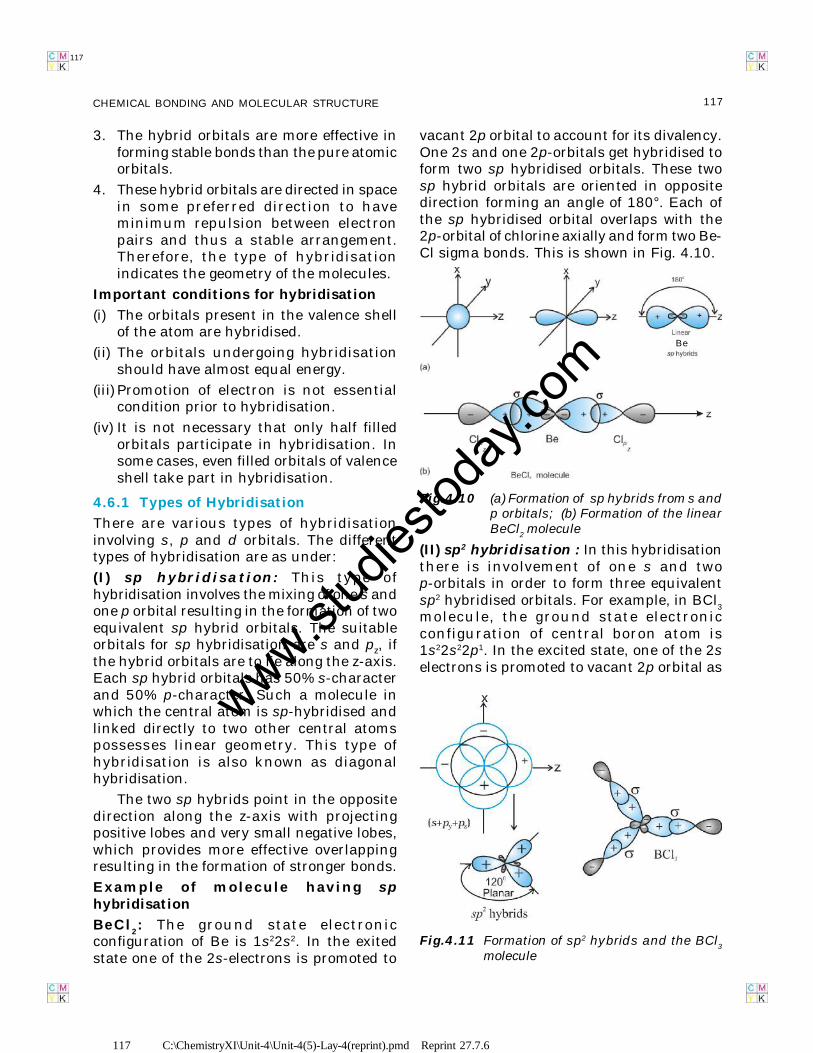
(I) sp hybridisation: This type ofhybridisation involves the mixing of one s andone p orbital resulting in the formation of twoequivalent sp hybrid orbitals. The suitableorbitals for sp hybridisation are s and pz, ifthe hybrid orbitals are to lie along the z-axis.Each sp hybrid orbitals has 50% s-characterand 50% p-character. Such a molecule inwhich the central atom is sp-hybridised andlinked directly to two other central atomspossesses linear geometry. This type ofhybridisation is also known as diagonalhybridisation.
The two sp hybrids point in the oppositedirection along the z-axis with projectingpositive lobes and very small negative lobes,which provides more effective overlappingresulting in the formation of stronger bonds.
Example of molecule having sphybridisation
BeCl2: The ground state electronic
configuration of Be is 1s22s2. In the exitedstate one of the 2s-electrons is promoted to
vacant 2p orbital to account for its divalency.One 2s and one 2p-orbitals get hybridised toform two sp hybridised orbitals. These twosp hybrid orbitals are oriented in oppositedirection forming an angle of 180°. Each ofthe sp hybridised orbital overlaps with the2p-orbital of chlorine axially and form two Be-Cl sigma bonds. This is shown in Fig. 4.10.
(II) sp2 hybridisation : In this hybridisationthere is involvement of one s and twop-orbitals in order to form three equivalentsp2 hybridised orbitals. For example, in BCl
3
molecule, the ground state electronicconfiguration of central boron atom is1s22s22p1. In the excited state, one of the 2selectrons is promoted to vacant 2p orbital as
Fig.4.10 (a) Formation of sp hybrids from s andp orbitals; (b) Formation of the linearBeCl
2 molecule
Be
Fig.4.11 Formation of sp2 hybrids and the BCl3
molecule
www.stud
iestod
ay.co
m
118 C:\ChemistryXI\Unit-4\Unit-4(5)-Lay-4(reprint).pmd Reprint 27.7.6
118 CHEMISTRY
118
a result boron has three unpaired electrons.These three orbitals (one 2s and two 2p)hybridise to form three sp2 hybrid orbitals.The three hybrid orbitals so formed areoriented in a trigonal planar arrangement andoverlap with 2p orbitals of chlorine to formthree B-Cl bonds. Therefore, in BCl
3(Fig.
4.11), the geometry is trigonal planar withClBCl bond angle of 120°.
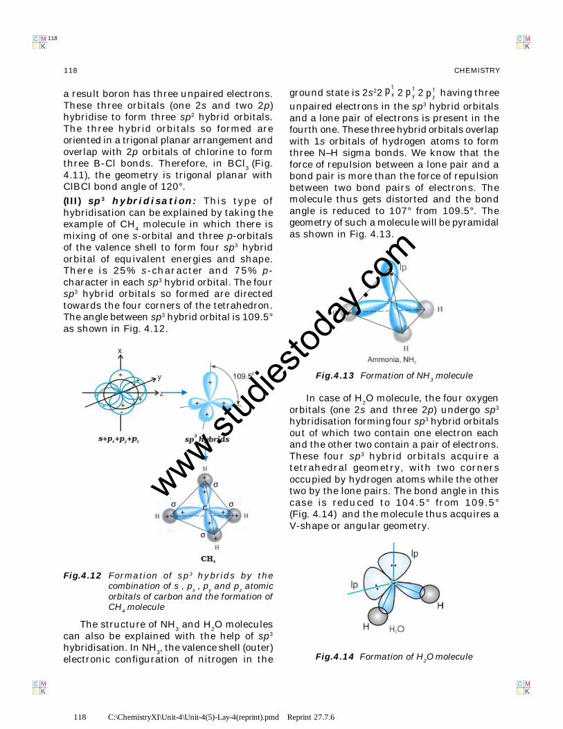
(III) sp3 hybridisation: This type ofhybridisation can be explained by taking theexample of CH
4 molecule in which there is
mixing of one s-orbital and three p-orbitalsof the valence shell to form four sp3 hybridorbital of equivalent energies and shape.There is 25% s-character and 75% p-character in each sp3 hybrid orbital. The foursp3 hybrid orbitals so formed are directedtowards the four corners of the tetrahedron.The angle between sp3 hybrid orbital is 109.5°as shown in Fig. 4.12.
Fig.4.12 Formation of sp3 hybrids by thecombination of s , p
x , p
y and p
z atomic
orbitals of carbon and the formation ofCH
4 molecule
σ
σ
σ
σ
The structure of NH3 and H
2O molecules
can also be explained with the help of sp3
hybridisation. In NH3, the valence shell (outer)
electronic configuration of nitrogen in the
ground state is 2s221xp 2 1
yp 2 1zp having three
unpaired electrons in the sp3 hybrid orbitalsand a lone pair of electrons is present in thefourth one. These three hybrid orbitals overlapwith 1s orbitals of hydrogen atoms to formthree N–H sigma bonds. We know that theforce of repulsion between a lone pair and abond pair is more than the force of repulsionbetween two bond pairs of electrons. Themolecule thus gets distorted and the bondangle is reduced to 107° from 109.5°. Thegeometry of such a molecule will be pyramidalas shown in Fig. 4.13.
Fig.4.13 Formation of NH3 molecule
In case of H2O molecule, the four oxygen
orbitals (one 2s and three 2p) undergo sp3
hybridisation forming four sp3 hybrid orbitalsout of which two contain one electron eachand the other two contain a pair of electrons.These four sp3 hybrid orbitals acquire atetrahedral geometry, with two cornersoccupied by hydrogen atoms while the othertwo by the lone pairs. The bond angle in thiscase is reduced to 104.5° from 109.5°(Fig. 4.14) and the molecule thus acquires aV-shape or angular geometry.
Fig.4.14 Formation of H2O molecule
www.stud
iestod
ay.co
m
119 C:\ChemistryXI\Unit-4\Unit-4(5)-Lay-4(reprint).pmd Reprint 27.7.6
119CHEMICAL BONDING AND MOLECULAR STRUCTURE
119
4.6.2 Other Examples of sp3, sp2 and spHybridisation
sp3 Hybridisation in C2H
6 molecule: In
ethane molecule both the carbon atomsassume sp3 hybrid state. One of the four sp3
hybrid orbitals of carbon atom overlaps axiallywith similar orbitals of other atom to formsp3-sp3 sigma bond while the other threehybrid orbitals of each carbon atom are usedin forming sp3–s sigma bonds with hydrogenatoms as discussed in section 4.6.1(iii).Therefore in ethane C–C bond length is 154pm and each C–H bond length is 109 pm.
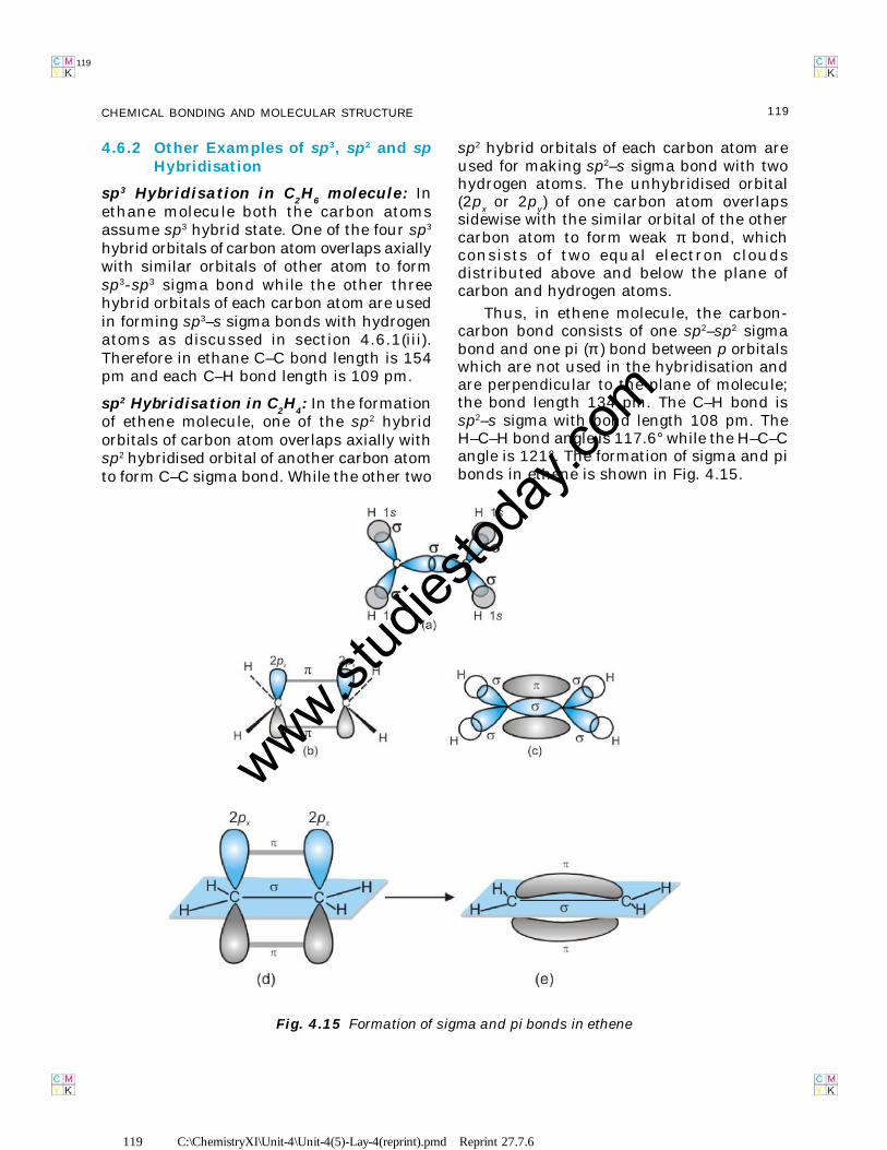
sp2 Hybridisation in C2H
4: In the formation
of ethene molecule, one of the sp2 hybridorbitals of carbon atom overlaps axially withsp2 hybridised orbital of another carbon atomto form C–C sigma bond. While the other two
sp2 hybrid orbitals of each carbon atom areused for making sp2–s sigma bond with twohydrogen atoms. The unhybridised orbital(2p
x or 2p
y) of one carbon atom overlaps
sidewise with the similar orbital of the othercarbon atom to form weak π bond, whichconsists of two equal electron cloudsdistributed above and below the plane ofcarbon and hydrogen atoms.
Thus, in ethene molecule, the carbon-carbon bond consists of one sp2–sp2 sigmabond and one pi (π ) bond between p orbitalswhich are not used in the hybridisation andare perpendicular to the plane of molecule;the bond length 134 pm. The C–H bond issp2–s sigma with bond length 108 pm. TheH–C–H bond angle is 117.6° while the H–C–Cangle is 121°. The formation of sigma and pibonds in ethene is shown in Fig. 4.15.
Fig. 4.15 Formation of sigma and pi bonds in ethene
www.stud
iestod
ay.co
m
120 C:\ChemistryXI\Unit-4\Unit-4(5)-Lay-4(reprint).pmd Reprint 27.7.6
120 CHEMISTRY
120
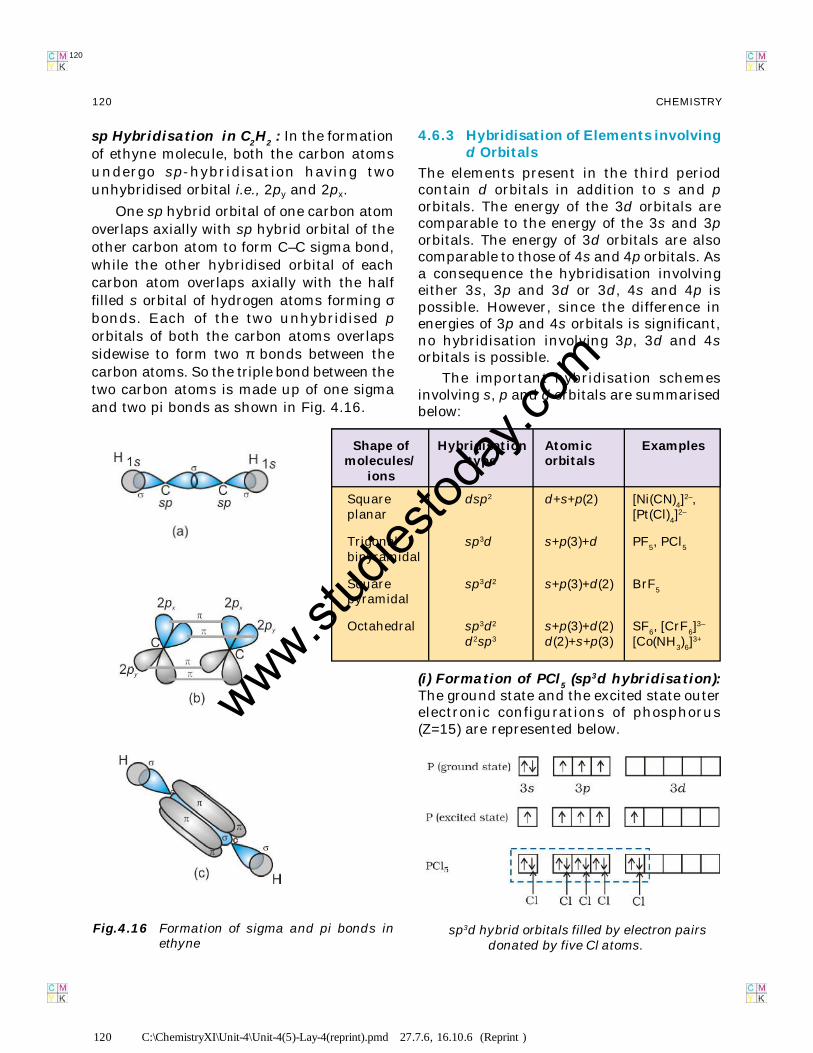
sp Hybridisation in C2H
2 : In the formation
of ethyne molecule, both the carbon atomsundergo sp-hybridisation having twounhybridised orbital i.e., 2py and 2px.
One sp hybrid orbital of one carbon atomoverlaps axially with sp hybrid orbital of theother carbon atom to form C–C sigma bond,while the other hybridised orbital of eachcarbon atom overlaps axially with the halffilled s orbital of hydrogen atoms forming σbonds. Each of the two unhybridised porbitals of both the carbon atoms overlapssidewise to form two π bonds between thecarbon atoms. So the triple bond between thetwo carbon atoms is made up of one sigmaand two pi bonds as shown in Fig. 4.16.
4.6.3 Hybridisation of Elements involvingd Orbitals
The elements present in the third periodcontain d orbitals in addition to s and porbitals. The energy of the 3d orbitals arecomparable to the energy of the 3s and 3porbitals. The energy of 3d orbitals are alsocomparable to those of 4s and 4p orbitals. Asa consequence the hybridisation involvingeither 3s, 3p and 3d or 3d, 4s and 4p ispossible. However, since the difference inenergies of 3p and 4s orbitals is significant,no hybridisation involving 3p, 3d and 4sorbitals is possible.
The important hybridisation schemesinvolving s, p and d orbitals are summarisedbelow:
Fig.4.16 Formation of sigma and pi bonds inethyne
Shape of Hybridisation Atomic Examplesmolecules/ type orbitals
ions
Square dsp2 d+s+p(2) [Ni(CN)4]2–,
planar [Pt(Cl)4]2–
Trigonal sp3d s+p(3)+d PF5, PCl5
bipyramidal
Square sp3d2 s+p(3)+d(2) BrF5
pyramidal
Octahedral sp3d2 s+p(3)+d(2) SF6, [CrF6]3–
d2sp3 d(2)+s+p(3) [Co(NH3)6]3+
(i) Formation of PCl5 (sp3d hybridisation):
The ground state and the excited state outerelectronic configurations of phosphorus(Z=15) are represented below.
sp3d hybrid orbitals filled by electron pairsdonated by five Cl atoms.
120 C:\ChemistryXI\Unit-4\Unit-4(5)-Lay-4(reprint).pmd 27.7.6, 16.10.6 (Reprint )
www.stud
iestod
ay.co
m
121 C:\ChemistryXI\Unit-4\Unit-4(5)-Lay-4(reprint).pmd Reprint 27.7.6
121CHEMICAL BONDING AND MOLECULAR STRUCTURE
121
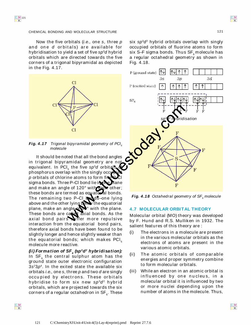
Now the five orbitals (i.e., one s, three pand one d orbitals) are available forhybridisation to yield a set of five sp3d hybridorbitals which are directed towards the fivecorners of a trigonal bipyramidal as depictedin the Fig. 4.17.
Fig. 4.17 Trigonal bipyramidal geometry of PCl5
molecule
It should be noted that all the bond anglesin trigonal bipyramidal geometry are notequivalent. In PCl
5 the five sp3d orbitals of
phosphorus overlap with the singly occupiedp orbitals of chlorine atoms to form five P–Clsigma bonds. Three P–Cl bond lie in one planeand make an angle of 120° with each other;these bonds are termed as equatorial bonds.The remaining two P–Cl bonds–one lyingabove and the other lying below the equatorialplane, make an angle of 90° with the plane.These bonds are called axial bonds. As theaxial bond pairs suffer more repulsiveinteraction from the equatorial bond pairs,therefore axial bonds have been found to beslightly longer and hence slightly weaker thanthe equatorial bonds; which makes PCl
5
molecule more reactive.
(ii) Formation of SF6 (sp3d2 hybridisation):
In SF6 the central sulphur atom has the
ground state outer electronic configuration3s23p4. In the exited state the available sixorbitals i.e., one s, three p and two d are singlyoccupied by electrons. These orbitalshybridise to form six new sp3d2 hybridorbitals, which are projected towards the sixcorners of a regular octahedron in SF
6. These
six sp3d2 hybrid orbitals overlap with singlyoccupied orbitals of fluorine atoms to formsix S–F sigma bonds. Thus SF
6molecule has
a regular octahedral geometry as shown inFig. 4.18.
sp3d2 hybridisation
4.7 MOLECULAR ORBITAL THEORY
Molecular orbital (MO) theory was developedby F. Hund and R.S. Mulliken in 1932. Thesalient features of this theory are :
(i) The electrons in a molecule are presentin the various molecular orbitals as theelectrons of atoms are present in thevarious atomic orbitals.
(ii) The atomic orbitals of comparableenergies and proper symmetry combineto form molecular orbitals.
(iii) While an electron in an atomic orbital isinfluenced by one nucleus, in amolecular orbital it is influenced by twoor more nuclei depending upon thenumber of atoms in the molecule. Thus,
Fig. 4.18 Octahedral geometry of SF6 molecule
www.stud
iestod
ay.co
m
122 C:\ChemistryXI\Unit-4\Unit-4(5)-Lay-4(reprint).pmd Reprint 27.7.6
122 CHEMISTRY
122
an atomic orbital is monocentric whilea molecular orbital is polycentric.
(iv) The number of molecular orbital formedis equal to the number of combiningatomic orbitals. When two atomicorbitals combine, two molecular orbitalsare formed. One is known as bondingmolecular orbital while the other iscalled antibonding molecular orbital.
(v) The bonding molecular orbital has lowerenergy and hence greater stability thanthe corresponding antibondingmolecular orbital.
(vi) Just as the electron probabilitydistribution around a nucleus in anatom is given by an atomic orbital, theelectron probability distribution arounda group of nuclei in a molecule is givenby a molecular orbital.
(vii) The molecular orbitals like atomicorbitals are filled in accordance with theaufbau principle obeying the Pauli’sexclusion principle and the Hund’s rule.
4.7.1 Formation of Molecular OrbitalsLinear Combination of AtomicOrbitals (LCAO)
According to wave mechanics, the atomicorbitals can be expressed by wave functions(ψ ’s) which represent the amplitude of theelectron waves. These are obtained from thesolution of Schrödinger wave equation.However, since it cannot be solved for anysystem containing more than one electron,molecular orbitals which are one electronwave functions for molecules are difficult toobtain directly from the solution ofSchrödinger wave equation. To overcome thisproblem, an approximate method known aslinear combination of atomic orbitals(LCAO) has been adopted.
Let us apply this method to thehomonuclear diatomic hydrogen molecule.Consider the hydrogen molecule consistingof two atoms A and B. Each hydrogen atomin the ground state has one electron in 1sorbital. The atomic orbitals of these atomsmay be represented by the wave functions ψ
A
and ψB. Mathematically, the formation of
molecular orbitals may be described by thelinear combination of atomic orbitals that cantake place by addition and by subtraction ofwave functions of individual atomic orbitalsas shown below :
ψMO
= ψA + ψ
B
Therefore, the two molecular orbitalsσ and σ* are formed as :
σ = ψA + ψ
B
σ* = ψA – ψ
B
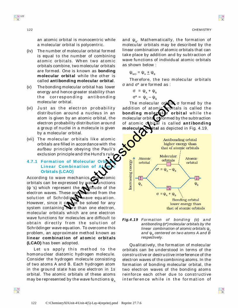
The molecular orbital σ formed by theaddition of atomic orbitals is called thebonding molecular orbital while themolecular orbital σ* formed by the subtractionof atomic orbital is called antibondingmolecular orbital as depicted in Fig. 4.19.
Fig.4.19 Formation of bonding (σ) andantibonding (σ*) molecular orbitals by thelinear combination of atomic orbitals ψ
A
and ψB centered on two atoms A and B
respectively.
Qualitatively, the formation of molecularorbitals can be understood in terms of theconstructive or destructive interference of theelectron waves of the combining atoms. In theformation of bonding molecular orbital, thetwo electron waves of the bonding atomsreinforce each other due to constructiveinterference while in the formation of
σ* = ψA – ψB
ψAψB
σ = ψA + ψB
www.stud
iestod
ay.co
m
123 C:\ChemistryXI\Unit-4\Unit-4(5)-Lay-4(reprint).pmd Reprint 27.7.6
123CHEMICAL BONDING AND MOLECULAR STRUCTURE
123
antibonding molecular orbital, the electronwaves cancel each other due to destructiveinterference. As a result, the electron densityin a bonding molecular orbital is locatedbetween the nuclei of the bonded atomsbecause of which the repulsion between thenuclei is very less while in case of anantibonding molecular orbital, most of theelectron density is located away from thespace between the nuclei. Infact, there is anodal plane (on which the electron density iszero) between the nuclei and hence therepulsion between the nuclei is high.Electrons placed in a bonding molecularorbital tend to hold the nuclei together andstabilise a molecule. Therefore, a bondingmolecular orbital always possesses lowerenergy than either of the atomic orbitals thathave combined to form it. In contrast, theelectrons placed in the antibonding molecularorbital destabilise the molecule. This isbecause the mutual repulsion of the electronsin this orbital is more than the attractionbetween the electrons and the nuclei, whichcauses a net increase in energy.
It may be noted that the energy of theantibonding orbital is raised above the energyof the parent atomic orbitals that havecombined and the energy of the bondingorbital has been lowered than the parentorbitals. The total energy of two molecularorbitals, however, remains the same as thatof two original atomic orbitals.
4.7.2 Conditions for the Combination ofAtomic Orbitals
The linear combination of atomic orbitals toform molecular orbitals takes place only if thefollowing conditions are satisfied:
1.The combining atomic orbitals musthave the same or nearly the same energy.This means that 1s orbital can combine withanother 1s orbital but not with 2s orbitalbecause the energy of 2s orbital is appreciablyhigher than that of 1s orbital. This is nottrue if the atoms are very different.
2.The combining atomic orbitals musthave the same symmetry about the
molecular axis. By convention z-axis istaken as the molecular axis. It is importantto note that atomic orbitals having sameor nearly the same energy will not combineif they do not have the same symmetry.For example, 2p
z orbital of one atom can
combine with 2pz orbital of the other atom
but not with the 2px or 2p
y orbitals because
of their different symmetries.
3.The combining atomic orbitals mustoverlap to the maximum extent. Greaterthe extent of overlap, the greater will be theelectron-density between the nuclei of amolecular orbital.
4.7.3 Types of Molecular Orbitals
Molecular orbitals of diatomic molecules aredesignated as σ (sigma), π (pi), δ (delta), etc.
In this nomenclature, the sigma (σ)molecular orbitals are symmetrical aroundthe bond-axis while pi (π) molecular orbitalsare not symmetrical. For example, the linearcombination of 1s orbitals centered on twonuclei produces two molecular orbitals whichare symmetrical around the bond-axis. Suchmolecular orbitals are of the σ type and aredesignated as σ1s and σ*1s [Fig. 4.20(a),page124]. If internuclear axis is taken to be inthe z-direction, it can be seen that a linearcombination of 2pz- orbitals of two atomsalso produces two sigma molecular orbitalsdesignated as σ2pz and σ*2pz. [Fig. 4.20(b)]
Molecular orbitals obtained from 2px and2py orbitals are not symmetrical around thebond axis because of the presence of positivelobes above and negative lobes below themolecular plane. Such molecular orbitals, arelabelled as π and π* [Fig. 4.20(c)]. A π bondingMO has larger electron density above andbelow the inter-nuclear axis. The π*antibonding MO has a node between thenuclei.
4.7.4 Energy Level Diagram for MolecularOrbitals
We have seen that 1s atomic orbitals on twoatoms form two molecular orbitals designatedas σ1s and σ*1s. In the same manner, the 2sand 2p atomic orbitals (eight atomic orbitals
www.stud
iestod
ay.co
m

124 C:\ChemistryXI\Unit-4\Unit-4(5)-Lay-4(reprint).pmd Reprint 27.7.6
124 CHEMISTRY
124
Fig. 4.20 Contours and energies of bonding and antibonding molecular orbitals formed throughcombinations of (a) 1s atomic orbitals; (b) 2pz atomic orbitals and (c) 2px atomic orbitals.
on two atoms) give rise to the following eightmolecular orbitals:
Antibonding MOs σ*2s σ*2pz
π*2px
π*2py
Bonding MOs σ2s σ2pz
π2px
π2py
The energy levels of these molecularorbitals have been determined experimentallyfrom spectroscopic data for homonucleardiatomic molecules of second row elementsof the periodic table. The increasing order of
www.stud
iestod
ay.co
m
125 C:\ChemistryXI\Unit-4\Unit-4(5)-Lay-4(reprint).pmd Reprint 27.7.6
125CHEMICAL BONDING AND MOLECULAR STRUCTURE
125
energies of various molecular orbitals for O2
and F2 is given below :
σ1s < σ*1s < σ2s < σ*2s <σ2pz<(π 2p
x= π 2p
y)
< (π *2px= π *2p
y)<σ*2p
z
However, this sequence of energy levels ofmolecular orbitals is not correct for theremaining molecules Li
2, Be
2, B
2, C
2, N
2. For
instance, it has been observed experimentallythat for molecules such as B
2, C
2, N
2 etc. the
increasing order of energies of variousmolecular orbitals is
σ1s < σ*1s < σ2s < σ*2s < (π 2px= π 2p
y) <σ2p
z
< (π *2px= π *2p
y) < σ*2p
z
The important characteristic feature ofthis order is that the energy of σ2pz
molecular orbital is higher than that ofπ 2px and π 2py molecular orbitals.
4.7.5 Electronic Configuration andMolecular Behaviour
The distribution of electrons among variousmolecular orbitals is called the electronicconfiguration of the molecule. From theelectronic configuration of the molecule, it ispossible to get important information aboutthe molecule as discussed below.
Stability of Molecules: If Nb is the number
of electrons occupying bonding orbitals andN
a the number occupying the antibonding
orbitals, then
(i) the molecule is stable if Nb is greater thanNa, and
(ii) the molecule is unstable if Nb is lessthan Na.
In (i) more bonding orbitals are occupiedand so the bonding influence is stronger and astable molecule results. In (ii) the antibondinginfluence is stronger and therefore the moleculeis unstable.
Bond order
Bond order (b.o.) is defined as one half thedifference between the number of electronspresent in the bonding and the antibondingorbitals i.e.,
Bond order (b.o.) = € (Nb–N
a)
The rules discussed above regarding thestability of the molecule can be restated interms of bond order as follows: A positive bondorder (i.e., N
b> N
a) means a stable molecule
while a negative (i.e., Nb<N
a) or zero (i.e.,
Nb
= Na) bond order means an unstable
molecule.
Nature of the bond
Integral bond order values of 1, 2 or 3correspond to single, double or triple bondsrespectively as studied in the classicalconcept.
Bond-length
The bond order between two atoms in amolecule may be taken as an approximatemeasure of the bond length. The bond lengthdecreases as bond order increases.
Magnetic nature
If all the molecular orbitals in a molecule aredoubly occupied, the substance isdiamagnetic (repelled by magnetic field).However if one or more molecular orbitals aresingly occupied it is paramagnetic (attractedby magnetic field), e.g., O
2 molecule.
4.8 BONDING IN SOME HOMONUCLEARDIATOMIC MOLECULES
In this section we shall discuss bonding insome homonuclear diatomic molecules.
1. Hydrogen molecule (H2 ): It is formed bythe combination of two hydrogen atoms. Eachhydrogen atom has one electron in 1s orbital.Therefore, in all there are two electrons inhydrogen molecule which are present in σ1smolecular orbital. So electronic configurationof hydrogen molecule is
H2 : (σ1s)2
The bond order of H2 molecule can be
calculated as given below:
Bond order = b aN N 2 01
2 2− −
= =
This means that the two hydrogen atomsare bonded together by a single covalent bond.The bond dissociation energy of hydrogenmolecule has been found to be 438 kJ mol–1
www.stud
iestod
ay.co
m
126 C:\ChemistryXI\Unit-4\Unit-4(5)-Lay-4(reprint).pmd Reprint 27.7.6
126 CHEMISTRY
126
and bond length equal to 74 pm. Since nounpaired electron is present in hydrogenmolecule, therefore, it is diamagnetic.
2. Helium molecule (He2 ): The electronicconfiguration of helium atom is 1s2. Eachhelium atom contains 2 electrons, therefore,in He
2 molecule there would be 4 electrons.
These electrons will be accommodated in σ1sand σ*1s molecular orbitals leading toelectronic configuration:
He2: (σ1s)2 (σ*1s)2
Bond order of He2is €(2 – 2) = 0
He2molecule is therefore unstable and does
not exist.
Similarly, it can be shown that Be2molecule
(σ1s)2 (σ*1s)2 (σ2s)2 (σ*2s)2 also does not exist.
3. Lithium molecule (Li2 ): The electronicconfiguration of lithium is 1s2, 2s1 . There aresix electrons in Li
2. The electronic
configuration of Li2 molecule, therefore, is
Li2 : (σ1s)2 (σ*1s)2 (σ2s)2
The above configuration is also written asKK(σ2s)2 where KK represents the closed Kshell structure (σ1s)2 (σ*1s)2.
From the electronic configuration of Li2
molecule it is clear that there are fourelectrons present in bonding molecularorbitals and two electrons present inantibonding molecular orbitals. Its bondorder, therefore, is € (4 – 2) = 1. It meansthat Li
2 molecule is stable and since it has
no unpaired electrons it should bediamagnetic. Indeed diamagnetic Li
2
molecules are known to exist in the vapourphase.
4. Carbon molecule (C2 ): The electronicconfiguration of carbon is 1s2 2s2 2p2. Thereare twelve electrons in C2. The electronicconfiguration of C2 molecule, therefore, is
C2 : 2 2 2 2 2 2( 1 ) ( *1 ) ( 2 ) ( * 2 ) ( 2 2 )σ σ σ σ =x ys s s s p pπ π
or 2 2 2 2( ) ( * ) ( )2 2 2 2σ σ =KK s s p pπ πx y
The bond order of C2 is € (8 – 4) = 2 and
C2 should be diamagnetic. Diamagnetic C
2
molecules have indeed been detected invapour phase. It is important to note that
double bond in C2 consists of both pi bonds
because of the presence of four electrons intwo pi molecular orbitals. In most of the othermolecules a double bond is made up of asigma bond and a pi bond. In a similar fashionthe bonding in N
2 molecule can be discussed.
5. Oxygen molecule (O2 ): The electronicconfiguration of oxygen atom is 1s2 2s2 2p4.Each oxygen atom has 8 electrons, hence, inO2 molecule there are 16 electrons. Theelectronic configuration of O2 molecule,therefore, is
2 2 2 2 22O : 1 *1 2 *2 2pσ σ σ σ σ z( s) ( s) ( s) ( s) ( )
( ) ( )2 2 1 1 2 2 * 2 * 2≡ ≡x y x yp p p pπ π π π or
( ) ( )2 2 2
z2
2 2 1 1y x y
KK ( 2 ) ( * 2 ) ( 2 )O :
2 2 , * 2 * 2
σ σ σ
≡ ≡
s s p
p p p pπ π π πx
From the electronic configuration of O2
molecule it is clear that ten electrons arepresent in bonding molecular orbitals and sixelectrons are present in antibondingmolecular orbitals. Its bond order, therefore,is
[ ] [ ]b a
1 1Bond order 10 6 2
2 2= − = − =N N
So in oxygen molecule, atoms are held bya double bond. Moreover, it may be noted thatit contains two unpaired electrons in π *2p
x
and π *2py molecular orbitals, therefore, O2
molecule should be paramagnetic, aprediction that corresponds toexperimental observation. In this way, thetheory successfully explains the paramagneticnature of oxygen.
Similarly, the electronic configurations ofother homonuclear diatomic molecules of thesecond row of the periodic table can bewritten. In Fig.4.21 are given the molecularorbital occupancy and molecular propertiesfor B
2 through Ne
2. The sequence of MOs and
their electron population are shown. The bondenergy, bond length, bond order, magneticproperties and valence electron configurationappear below the orbital diagrams.
www.stud
iestod
ay.co
m
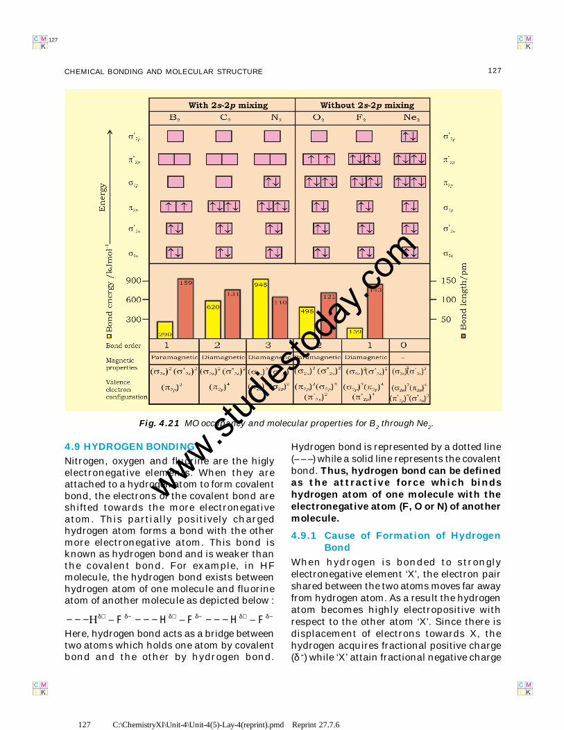
127 C:\ChemistryXI\Unit-4\Unit-4(5)-Lay-4(reprint).pmd Reprint 27.7.6
127CHEMICAL BONDING AND MOLECULAR STRUCTURE
127
4.9 HYDROGEN BONDING
Nitrogen, oxygen and fluorine are the higlyelectronegative elements. When they areattached to a hydrogen atom to form covalentbond, the electrons of the covalent bond areshifted towards the more electronegativeatom. This partially positively chargedhydrogen atom forms a bond with the othermore electronegative atom. This bond isknown as hydrogen bond and is weaker thanthe covalent bond. For example, in HFmolecule, the hydrogen bond exists betweenhydrogen atom of one molecule and fluorineatom of another molecule as depicted below :
F H F H Fδ+ δ− δ+ δ− δ+ δ−− − − − − − − − −Here, hydrogen bond acts as a bridge betweentwo atoms which holds one atom by covalentbond and the other by hydrogen bond.
Hydrogen bond is represented by a dotted line(– – –) while a solid line represents the covalentbond. Thus, hydrogen bond can be definedas the attractive force which bindshydrogen atom of one molecule with theelectronegative atom (F, O or N) of anothermolecule.
4.9.1 Cause of Formation of HydrogenBond
When hydrogen is bonded to stronglyelectronegative element ‘X’, the electron pairshared between the two atoms moves far awayfrom hydrogen atom. As a result the hydrogenatom becomes highly electropositive withrespect to the other atom ‘X’. Since there isdisplacement of electrons towards X, thehydrogen acquires fractional positive charge(δ +) while ‘X’ attain fractional negative charge
Fig. 4.21 MO occupancy and molecular properties for B2 through Ne2.
www.stud
iestod
ay.co
m
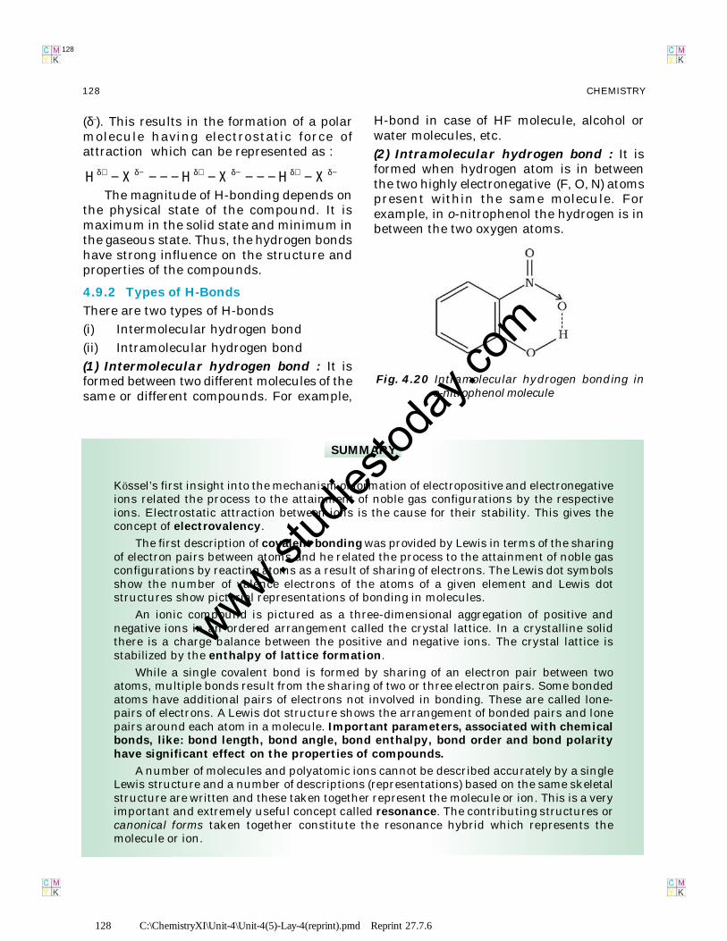
128 C:\ChemistryXI\Unit-4\Unit-4(5)-Lay-4(reprint).pmd Reprint 27.7.6
128 CHEMISTRY
128
SUMMARY
Kössel’s first insight into the mechanism of formation of electropositive and electronegativeions related the process to the attainment of noble gas configurations by the respectiveions. Electrostatic attraction between ions is the cause for their stability. This gives theconcept of electrovalency.
The first description of covalent bonding was provided by Lewis in terms of the sharingof electron pairs between atoms and he related the process to the attainment of noble gasconfigurations by reacting atoms as a result of sharing of electrons. The Lewis dot symbolsshow the number of valence electrons of the atoms of a given element and Lewis dotstructures show pictorial representations of bonding in molecules.
An ionic compound is pictured as a three-dimensional aggregation of positive andnegative ions in an ordered arrangement called the crystal lattice. In a crystalline solidthere is a charge balance between the positive and negative ions. The crystal lattice isstabilized by the enthalpy of lattice formation.
While a single covalent bond is formed by sharing of an electron pair between twoatoms, multiple bonds result from the sharing of two or three electron pairs. Some bondedatoms have additional pairs of electrons not involved in bonding. These are called lone-pairs of electrons. A Lewis dot structure shows the arrangement of bonded pairs and lonepairs around each atom in a molecule. Important parameters, associated with chemicalbonds, like: bond length, bond angle, bond enthalpy, bond order and bond polarityhave significant effect on the properties of compounds.
A number of molecules and polyatomic ions cannot be described accurately by a singleLewis structure and a number of descriptions (representations) based on the same skeletalstructure are written and these taken together represent the molecule or ion. This is a veryimportant and extremely useful concept called resonance. The contributing structures orcanonical forms taken together constitute the resonance hybrid which represents themolecule or ion.
(δ–). This results in the formation of a polarmolecule having electrostatic force ofattraction which can be represented as :
H X H X H Xδ+ δ− δ+ δ− δ+ δ−− − − − − − − − −The magnitude of H-bonding depends on
the physical state of the compound. It ismaximum in the solid state and minimum inthe gaseous state. Thus, the hydrogen bondshave strong influence on the structure andproperties of the compounds.
4.9.2 Types of H-Bonds
There are two types of H-bonds
(i) Intermolecular hydrogen bond
(ii) Intramolecular hydrogen bond
(1) Intermolecular hydrogen bond : It isformed between two different molecules of thesame or different compounds. For example,
H-bond in case of HF molecule, alcohol orwater molecules, etc.
(2) Intramolecular hydrogen bond : It isformed when hydrogen atom is in betweenthe two highly electronegative (F, O, N) atomspresent within the same molecule. Forexample, in o-nitrophenol the hydrogen is inbetween the two oxygen atoms.
Fig. 4.20 Intramolecular hydrogen bonding ino-nitrophenol molecule
www.stud
iestod
ay.co
m
129 C:\ChemistryXI\Unit-4\Unit-4(5)-Lay-4(reprint).pmd Reprint 27.7.6
129CHEMICAL BONDING AND MOLECULAR STRUCTURE
129
The VSEPR model used for predicting the geometrical shapes of molecules is based onthe assumption that electron pairs repel each other and, therefore, tend to remain as farapart as possible. According to this model, molecular geometry is determined by repulsionsbetween lone pairs and lone pairs ; lone pairs and bonding pairs and bonding pairs andbonding pairs. The order of these repulsions being : lp-lp > lp-bp > bp-bp
The valence bond (VB) approach to covalent bonding is basically concerned with theenergetics of covalent bond formation about which the Lewis and VSEPR models are silent.Basically the VB theory discusses bond formation in terms of overlap of orbitals. Forexample the formation of the H2 molecule from two hydrogen atoms involves the overlap ofthe 1s orbitals of the two H atoms which are singly occupied. It is seen that the potentialenergy of the system gets lowered as the two H atoms come near to each other. At theequilibrium inter-nuclear distance (bond distance) the energy touches a minimum. Anyattempt to bring the nuclei still closer results in a sudden increase in energy and consequentdestabilization of the molecule. Because of orbital overlap the electron density between thenuclei increases which helps in bringing them closer. It is however seen that the actualbond enthalpy and bond length values are not obtained by overlap alone and other variableshave to be taken into account.
For explaining the characteristic shapes of polyatomic molecules Pauling introducedthe concept of hybridisation of atomic orbitals. sp,sp2, sp3 hybridizations of atomic orbitalsof Be, B,C, N and O are used to explain the formation and geometrical shapes of moleculeslike BeCl2, BCl3, CH4, NH3 and H2O. They also explain the formation of multiple bonds inmolecules like C2H2 and C2H4.
The molecular orbital (MO) theory describes bonding in terms of the combinationand arrangment of atomic orbitals to form molecular orbitals that are associated with themolecule as a whole. The number of molecular orbitals are always equal to the number ofatomic orbitals from which they are formed. Bonding molecular orbitals increase electrondensity between the nuclei and are lower in energy than the individual atomic orbitals.Antibonding molecular orbitals have a region of zero electron density between the nucleiand have more energy than the individual atomic orbitals.
The electronic configuration of the molecules is written by filling electrons in themolecular orbitals in the order of increasing energy levels. As in the case of atoms, thePauli exclusion principle and Hund’s rule are applicable for the filling of molecular orbitals.Molecules are said to be stable if the number of elctrons in bonding molecular orbitals isgreater than that in antibonding molecular orbitals.
Hydrogen bond is formed when a hydrogen atom finds itself between two highlyelectronegative atoms such as F, O and N. It may be intermolecular (existing between twoor more molecules of the same or different substances) or intramolecular (present withinthe same molecule). Hydrogen bonds have a powerful effect on the structure and propertiesof many compounds.
EXERCISES
4.1 Explain the formation of a chemical bond.
4.2 Write Lewis dot symbols for atoms of the following elements : Mg, Na, B, O, N, Br.
4.3 Write Lewis symbols for the following atoms and ions:
S and S2–; Al and Al3+; H and H–
4.4 Draw the Lewis structures for the following molecules and ions :
H2S, SiCl4, BeF2,23CO − , HCOOH
www.stud
iestod
ay.co
m
130 C:\ChemistryXI\Unit-4\Unit-4(5)-Lay-4(reprint).pmd Reprint 27.7.6
130 CHEMISTRY
130
4.5 Define octet rule. Write its significance and limitations.
4.6 Write the favourable factors for the formation of ionic bond.
4.7 Discuss the shape of the following molecules using the VSEPR model:
BeCl2, BCl3, SiCl4, AsF5, H2S, PH3
4.8 Although geometries of NH3 and H2O molecules are distorted tetrahedral, bondangle in water is less than that of ammonia. Discuss.
4.9 How do you express the bond strength in terms of bond order ?
4.10 Define the bond length.
4.11 Explain the important aspects of resonance with reference to the 23CO − ion.
4.12 H3PO3 can be represented by structures 1 and 2 shown below. Can these twostructures be taken as the canonical forms of the resonance hybrid representingH3PO3 ? If not, give reasons for the same.
4.13 Write the resonance structures for SO3, NO2 and 3NO− .
4.14 Use Lewis symbols to show electron transfer between the following atoms to formcations and anions : (a) K and S (b) Ca and O (c) Al and N.
4.15 Although both CO2 and H2O are triatomic molecules, the shape of H2O molecule isbent while that of CO2 is linear. Explain this on the basis of dipole moment.
4.16 Write the significance/applications of dipole moment.
4.17 Define electronegativity. How does it differ from electron gain enthalpy ?
4.18 Explain with the help of suitable example polar covalent bond.
4.19 Arrange the bonds in order of increasing ionic character in the molecules: LiF, K2O,N2, SO2 and ClF3.
4.20 The skeletal structure of CH3COOH as shown below is correct, but some of thebonds are shown incorrectly. Write the correct Lewis structure for acetic acid.
4.21 Apart from tetrahedral geometry, another possible geometry for CH4 is square planarwith the four H atoms at the corners of the square and the C atom at its centre.Explain why CH4 is not square planar ?
4.22 Explain why BeH2 molecule has a zero dipole moment although the Be–H bonds arepolar.
4.23 Which out of NH3 and NF3 has higher dipole moment and why ?
4.24 What is meant by hybridisation of atomic orbitals? Describe the shapes of sp, sp2,sp3 hybrid orbitals.
4.25 Describe the change in hybridisation (if any) of the Al atom in the following reaction.
3 4AlCl Cl AlCl− −+ →
www.stud
iestod
ay.co
m

131 C:\ChemistryXI\Unit-4\Unit-4(5)-Lay-4(reprint).pmd Reprint 27.7.6
131CHEMICAL BONDING AND MOLECULAR STRUCTURE
131
4.26 Is there any change in the hybridisation of B and N atoms as a result of the followingreaction ?
3 3 3 3BF NH F B.NH+ →
4.27 Draw diagrams showing the formation of a double bond and a triple bond betweencarbon atoms in C2H4 and C2H2 molecules.
4.28 What is the total number of sigma and pi bonds in the following molecules ?
(a) C2H2 (b) C2H4
4.29 Considering x-axis as the internuclear axis which out of the following will not forma sigma bond and why? (a) 1s and 1s (b) 1s and 2px ; (c) 2py and 2py
(d) 1s and 2s.
4.30 Which hybrid orbitals are used by carbon atoms in the following molecules ?
CH3–CH3; (b) CH3–CH=CH2; (c) CH3-CH2-OH; (d) CH3-CHO (e) CH3COOH
4.31 What do you understand by bond pairs and lone pairs of electrons ? Illustrate bygiving one exmaple of each type.
4.32 Distinguish between a sigma and a pi bond.
4.33 Explain the formation of H2 molecule on the basis of valence bond theory.
4.34 Write the important conditions required for the linear combination of atomic orbitalsto form molecular orbitals.
4.35 Use molecular orbital theory to explain why the Be2 molecule does not exist.
4.36 Compare the relative stability of the following species and indicate their magneticproperties;
2 2 2O ,O ,O+ − (superoxide), 22O − (peroxide)
4.37 Write the significance of a plus and a minus sign shown in representing the orbitals.
4.38 Describe the hybridisation in case of PCl5. Why are the axial bonds longer ascompared to equatorial bonds ?
4.39 Define hydrogen bond. Is it weaker or stronger than the van der Waals forces?
4.40 What is meant by the term bond order ? Calculate the bond order of : N2, O2, O2
+
and O2
–.
www.stud
iestod
ay.co
m