chemagnetics double-resonance hx cp/mas nmr probe …
TRANSCRIPT

Chemagnetics
™
Double-ResonanceHX CP/MAS NMRProbe Installation
Varian NMR Spectrometer Systems
Pub. No. 01-999155-00, Rev. A0101

01-999155-00 A0101 Chemagnetcis HX CP/MAS NMR Probes Installation
1
Chemagnetics Double-Resonance HX CP/MAS NMR Probes
Installation, Testing, and Specifications
•
Overview, this page
•
Safety Precautions, page 4
•
Rotor Composition, page 6
•
MAS Speed Controller and Solids Temperature Controller, page 8
•
Mounting the Stand and Probe, page 10
•
Installing the VT Upper Stack, page 11
•
Connecting Pneumatics and RF Cables, page 11
•
Spinning the Sample, page 14
•
Changing Plug-ins on APEX and T3 Probes, page 17
•
Finding a Resonance, page 20
•
Tuning MAS Probes, page 21
•
Solids Amplifiers, page 24
•
Setting Initial Input Pulse Power for Probes, page 25
•
Testing MAS Probes, page 26
•
Verifying VT Operation (Optional), page 38
•
Preparing the Sample, page 43
•
Acquiring Data from Your Samples, page 48
•
Probe Installation Sheet, page 52
Overview
This manual covers installation and testing of Varian Chemagnetics APEX and T3 double-resonance MAS probes for widebore (89 mm) magnets.
Pub. No. 01-999155-00, Rev. A0101

Chemagnetics Double-Resonance HX CP/MAS NMR Probes
2
Chemagnetcis HX CP/MAS NMR Probes Installation 01-999155-00 A0101
Table 1.
Varian Chemagnetics APEX Double Resonance HX Probes
Magnet
*
(MHz)
Module X-Band Nucleus Range
Probe Part Number
200 2.5mm Vespel
29
Si-
31
P MPRB200-390
200 3.2mm Vespel
29
Si-
31
P MPRB200-395
200 4.0mm Kel-F
2
H-
31
P MPRB200-126
200 4.0mm Vespel
2
H-
31
P MPRB200-175
200 5.0mm Ceramic
17
O-
31
P MPRB200-156
200 5.0mm Kel-F
17
O-
31
P MPRB200-174
200 5.0mm Vespel
17
O-
31
P MPRB200-173
200 6.0mm Ceramic
15
N-
31
P MPRB200-382
200 6.0mm Kel-F
15
N-
31
P MPRB200-381
200 6.0mm Vespel
15
N-
31
P MPRB200-380
200 7.5mm Ceramic
15
N-
31
P MPRB200-116
200 7.5mm Kel-F
15
N-
31
P MPRB200-172
200 7.5mm Vespel
15
N-
31
P MPRB200-171
200 9.5mm Kel-F
15
N-
31
P MPRB200-211
200 9.5mm Vespel
15
N-
31
P MPRB200-460
200 14.0mm Kel-F
15
N-
31
P MPRB200-119
300 2.5mm Vespel
2
H-
31
P MPRB300-390
300 3.2mm Vespel
17
O-
31
P MPRB300-395
300 4.0mm Kel-F
15
N-
31
P MPRB300-126
300 4.0mm Vespel
15
N-
31
P MPRB300-175
300 5.0mm Ceramic
15
N-
31
P MPRB300-156
300 5.0mm Kel-F
15
N-
31
P MPRB300-174
300 5.0mm Vespel
15
N-
31
P MPRB300-173
300 6.0mm Ceramic
15
N-
31
P MPRB300-382
300 6.0mm Kel-F
15
N-
31
P MPRB300-381
300 6.0mm Vespel
15
N-
31
P MPRB300-380
300 7.5mm Ceramic
15
N-
31
P MPRB300-116
300 7.5mm Kel-F
15
N-
31
P MPRB300-172
300 7.5mm Vespel
15
N-
31
P MPRB300-171
300 9.5mm Kel-F
15
N-
31
P MPRB300-211
300 9.5mm Vespel
15
N-
31
P MPRB300-460
300 14.0mm Kel-F
15
N-
31
P MPRB300-119
360 2.5mm Vespel
15
N-
31
P MPRB360-390
360 3.2mm Vespel
15
N-
31
P MPRB360-395
360 4.0mm Kel-F
15
N-
31
P MPRB360-126
360 4.0mm Vespel
15
N-
31
P MPRB360-175
360 5.0mm Ceramic
15
N-
31
P MPRB360-156
360 5.0mm Kel-F
15
N-
31
P MPRB360-174
360 5.0mm Vespel
15
N-
31
P MPRB360-173
360 6.0mm Ceramic
15
N-
31
P MPRB360-382
360 6.0mm Kel-F
15
N-
31
P MPRB360-381
360 6.0mm Vespel
15N-31P MPRB360-380

01-999155-00 A0101 Chemagnetcis HX CP/MAS NMR Probes Installation 3
Overview
Table 2. Varian Chemagnetics T3 Double Resonance HX Probes
360 7.5mm Ceramic 15N-31P MPRB360-116
360 7.5mm Kel-F 15N-31P MPRB360-172
360 7.5mm Vespel 15N-31P MPRB360-171
360 9.5mm Kel-F 15N-31P MPRB360-211
360 9.5mm Vespel 15N-31P MPRB360-460
400 2.5mm Vespel 15N-31P MPRB400-390
400 3.2mm Vespel 15N-31P MPRB400-395
400 4.0mm Kel-F 15N-31P MPRB400-126
400 4.0mm Vespel 15N-31P MPRB400-175
400 5.0mm Ceramic 15N-31P MPRB400-156
400 5.0mm Kel-F 15N-31P MPRB400-174
400 5.0mm Vespel 15N-31P MPRB400-173
400 6.0mm Ceramic 15N-31P MPRB400-382
400 6.0mm Kel-F 15N-31P MPRB400-381
400 6.0mm Vespel 15N-31P MPRB400-380
400 7.5mm Ceramic 15N-31P MPRB400-116
400 7.5mm Kel-F 15N-31P MPRB400-172
400 7.5mm Vespel 15N-31P MPRB400-171
400 9.5mm Kel-F 15N-31P MPRB400-211
400 9.5mm Vespel 15N-31P MPRB400-460
*. All listed magnets are widebore (89 mm).
Magnet* (MHz)
Module X-Band Nucleus Range
Probe Part Number
400 2.5mm Vespel 15N-31P SPRB400-390
400 3.2mm Vespel 15N-31P SPRB400-395
400 4.0mm Kel-F 15N-31P SPRB400-126
400 4.0mm Vespel 15N-31P SPRB400-175
400 5.0mm Ceramic 15N-31P SPRB400-156
400 5.0mm Kel-F 15N-31P SPRB400-174
400 5.0mm Vespel 15N-31P SPRB400-173
400 6.0mm Ceramic 15N-31P SPRB400-382
400 6.0mm Kel-F 15N-31P SPRB400-381
400 6.0mm Vespel 15N-31P SPRB400-380
400 7.5mm Ceramic 15N-31P SPRB400-116
400 7.5mm Kel-F 15N-31P SPRB400-172
400 7.5mm Vespel 15N-31P SPRB400-171
400 9.5mm Kel-F 15N-31P SPRB400-211
400 9.5mm Vespel 15N-31P SPRB400-460
500 2.5mm Vespel 15N-31P SPRB500-390
500 3.2mm Vespel 15N-31P SPRB500-395
500 4.0mm Kel-F 15N-31P SPRB500-126
Magnet* (MHz)
Module X-Band Nucleus Range
Probe Part Number

Chemagnetics Double-Resonance HX CP/MAS NMR Probes
4 Chemagnetcis HX CP/MAS NMR Probes Installation 01-999155-00 A0101
Safety Precautions
WARNING: A projectile hazard exists if a spinning rotor explodes, resulting in injury. To prevent possible eye injury from an exploding rotor, avoid spinning rotors outside the magnet. If spinning a rotor outside the magnet is necessary, use a certified safety shield and full face shield at all times. Never use rotors that have been dropped onto a hard surface, since microcracks in the rotor material can cause rotor explosions at much lower spinning speeds than listed in Table 3.
CAUTION: Reduced probe life can result from a failure to maintain a clean and dry gas supply.
CAUTION: Probe damage can occur if the probe is dropped onto the tuning shafts. Hold the probe or keep at least one lock screw tightened to prevent the probe from slipping down the stand.
500 4.0mm Vespel 15N-31P SPRB500-175
500 5.0mm Ceramic 15N-31P SPRB500-156
500 5.0mm Kel-F 15N-31P SPRB500-174
500 5.0mm Vespel 15N-31P SPRB500-173
500 6.0mm Ceramic 15N-31P SPRB500-382
500 6.0mm Kel-F 15N-31P SPRB500-381
500 6.0mm Vespel 15N-31P SPRB500-380
500 7.5mm Ceramic 15N-31P SPRB500-116
500 7.5mm Kel-F 15N-31P SPRB500-172
500 7.5mm Vespel 15N-31P SPRB500-171
500 9.5mm Kel-F 15N-31P SPRB500-211
500 9.5mm Vespel 15N-31P SPRB500-460
600 2.5mm Vespel 15N-31P SPRB600-390
600 3.2mm Vespel 15N-31P SPRB600-395
600 4.0mm Kel-F 15N-31P SPRB600-126
600 4.0mm Vespel 15N-31P SPRB600-175
600 5.0mm Ceramic 15N-31P SPRB600-156
600 5.0mm Kel-F 15N-31P SPRB600-174
600 5.0mm Vespel 15N-31P SPRB600-173
600 6.0mm Ceramic 15N-31P SPRB600-382
600 6.0mm Kel-F 15N-31P SPRB600-381
600 6.0mm Vespel 15N-31P SPRB600-380
600 7.5mm Ceramic 15N-31P SPRB600-116
600 7.5mm Kel-F 15N-31P SPRB600-172
600 7.5mm Vespel 15N-31P SPRB600-171
*. All listed magnets are widebore (89 mm).
Magnet* (MHz)
Module X-Band Nucleus Range
Probe Part Number

01-999155-00 A0101 Chemagnetcis HX CP/MAS NMR Probes Installation 5
Safety Precautions
CAUTION: Magnet and probe stand damage can result from a sudden loss of pressure in the TMC antivibration legs if the probe stand nylon bolts are extended. For systems with TMC antivibration legs, do not lower the nylon bolts of the probe stand to the floor.
WARNING: Shock hazard can result in death or serious injury.Disable Spinsight with the STANDBY button in the Display icon bar whenever opening the probe or connecting cables. Disabling the acquisition process in Spinsight limits the possibility of accidental discharge of current or rf while working with the probe. Remember to click the ENABLE button when you wish to resume operation.
WARNING: Injury can occur if spinning rotors shatter or explode. Excessive spinning speeds can cause rotors to shatter and explode. Never spin rotors above specified speeds. For samples such as KBr that have densities above 3.0 g/cc, decrease the maximum spin rate by 35%.
WARNING: Damaged rotors can cause injury. Rotors must be handled with care. Never spin a rotor that has been dropped onto a hard surface. Tiny fractures, too small to see, can cause the rotor to explode when spinning.
CAUTION: Rotors and bearings can be damaged if drive or bearing air is decreased too rapidly. To prevent damage to the rotor or bearing, always smoothly decrease drive and bearing air until rotor stops, which the controller does automatically during STOP in Auto mode. Bearing air should be not be decreased below approximately 10 psi until the rotor comes to a complete stop.
CAUTION: Small scratches can damage a rotor. When removing spacers or digging out packed samples, take care not to gouge the rotor.
CAUTION: Use of the range extension hats with a single cap tune wand may result in damage to the wand.
CAUTION: The magic angle can be inadvertently misadjusted during probe tuning. Do not turn the chrome magic angle adjust knob while tuning the probe.
CAUTION: Do not mistakenly turn the Magic Angle adjust knob, which is silver in color, and set apart from the TUNE and MATCH knobs on both T3 and APEX probes.
CAUTION: The probe can be damaged when used with the 1-kW amplifiers. Be sure that you start with a(n) and sc(n) set low. Settings of a(n)=0.5 and sc(n)=0.3 are generally safe to start as long as the amplifiers have been properly padded to put out 1kW at maximum modulator and attenuator settings.
CAUTION: The probe and 1H amplifier can be damaged with a large aHdec value and long acquisition time. Reduce the value of aHdec by one half to one third of the 1H specification level for adamantane shimming.
CAUTION: The probe and magnet can be damaged if procedures are not followed carefully. Read the Solids Temperature Controller manual thoroughly before performing VT for the first time.
CAUTION: The probe can be damaged by impure or moist spinning, purge, or VT air. Use dry nitrogen for spinning, purge, and VT gas before

Chemagnetics Double-Resonance HX CP/MAS NMR Probes
6 Chemagnetcis HX CP/MAS NMR Probes Installation 01-999155-00 A0101
proceeding with temperatures above 150°C or below room temperature.
CAUTION: The magnet and probe can be damaged by improper VT gas exhaust. Do NOT continue with VT operation until VT gases are exhausted correctly.
CAUTION: The probe will be damaged if you exceed 80°C on a Kel-F module. If you are testing a probe with a Kel-F module, stop here and proceed with low temperature tests.
CAUTION: The probe can be damaged if the gas flow is disconnected too soon. DO NOT disconnect the gas flow to the upper stack until the temperature reading is at essentially room temperature for at least 20 minutes. Leaving the gas flow connected at all times is preferable.
CAUTION: The probe can be damaged by impure or moist spinning, purge, or VT air. Use dry nitrogen for spinning, purge, and VT gas before proceeding with temperatures above 150°C or below room temperature.
WARNING: Do not load explosives or labile compounds, including organic conductors if the possibility of explosion exists. Chemagnetics assumes no responsibility for any samples which detonate under the effects of sample spinning and/or high power rf application.
CAUTION: Use caution when working with electrically conductive samples. Such samples detune the probe, produce a longer 90° pulse for a given power level, and lower sensitivity. You must retune the probe as a result. Increasing transmitter power is more likely to result in probe arcing, causing damage to probe electronics.
CAUTION: To avoid the possibility of dropping the rotor and breaking it, always hold the rotor over a padded area while filling or emptying it. If the kel-F end cap is difficult to insert or remove, cool the end cap or the entire assembly. The differential shrinkage will loosen the fit.
CAUTION: Never use a magnetic metal tool to remove a sample. Such action will leave metallic marks on the inside of the rotor. These metal traces are difficult or impossible to remove.
Rotor CompositionRotors for solid-state NMR are made of zirconia, glass, or silicon nitride sleeves, with spacers and drive tips of various materials. For more information on preparing CP/MAS samples, refer to MAS Double Resonance Probe manual.
For high-speed rotors (3.2 and 2.5 mm diameters) tachometer sensing is on the top spacer, which extends from the top of the rotor. A black mark should be applied with a permanent black marker to the side of the spacer on the area that extends from the top of the rotor sleeve so that 50% of the circumference of the spacer is black. Zirconia rotors greater than 3.2 mm diameter have a laser-etched tachometer mark and no further markings should be applied. Silicon nitride (Si3N4) rotors should be marked with white enamel paint on the top 2–3 mm of the rotor sleeve so that 50% of the circumference is white. Glass CRAMPS rotors, 5.0 mm diameter, should be painted white on 50% of the circumference and marked

01-999155-00 A0101 Chemagnetcis HX CP/MAS NMR Probes Installation 7
Rotor Composition
black with permanent pen on 50% of the circumference at the top 2-3 mm of the glass rotor sleeve.
WARNING: A projectile hazard exists if a spinning rotor explodes, resulting in injury. To prevent possible eye injury from an exploding rotor, avoid spinning rotors outside the magnet. If spinning a rotor outside the magnet is necessary, use a certified safety shield and full face shield at all times. Never use rotors that have been dropped onto a hard surface, since microcracks in the rotor material can cause rotor explosions at much lower spinning speeds than listed in Table 3.
Table 3. Characteristics of Chemagnetics Rotors
Table 4. Characteristics of Chemagnetics MAS Modules
Rotor Material ColorMin Spin Rate (Hz)
Max Spin Rate Ambient (Hz)
Max Spin Rate VT (Hz)
14.0 mm,2.5 ml Vol.
Zirconia white, off-white, or yellow
500 3500 —
14.0 mm,2.1 ml Vol.
Zirconia white, off-white, or yellow
500 4500 —
9.5 mm Zirconia white, off-white, or yellow
20* 5500 5500
7.5 mm Zirconia white, off-white, or yellow
40* 7000 7000
7.5 mm Silicon nitride gray 40* 7000 7000
6.0 mm Zirconia white, off-white, or yellow
40* 9000 9000
6.0 mm Silicon nitride gray 40*
*. With optional MAT flow restrictor.
9000 9000
5.0 mm Zirconia white, off-white, or yellow
1000 12000 12000
5.0 mm Silicon nitride gray 1000 12000 12000
5.0 mm Glass clear 1000 6000 6000
4.0 mm Zirconia white, off-white, or yellow
1000 18000 16000
3.2 mm Zirconia white or off-white
3000 25000 —
2.5 mm Zirconia white or off-white
5000 30000 —
Module Material ColorRecommended Temperature Range (°C)
14.0 mm Vespel brown ambient
14.0 mm Ceramic off-white ambient
9.5 mm Vespel brown –150 to +250
9.5 mm Ceramic off-white –150 to +250
9.5 mm Kel-F translucent grey –150 to +80
7.5 mm Vespel brown –150 to +250
7.5 mm Ceramic off-white –150 to +250
7.5 mm Kel-F translucent grey –150 to +80

Chemagnetics Double-Resonance HX CP/MAS NMR Probes
8 Chemagnetcis HX CP/MAS NMR Probes Installation 01-999155-00 A0101
MAS Speed Controller and Solids Temperature ControllerThe MAS Speed Controller and Solids Temperature Controller are used with Chemagnetics VT CP/ MAS probes. These controllers handle all gas supply distribution to the probe. The supply line is permanently connected to the wall supply, which must be clean, dry air or nitrogen. The wall supply should be at a pressure not exceeding 150 psi (10 bar) and not less than 80 psi (6 bar) and be filtered appropriately (see the MAS Speed Controller manual for details).
CAUTION: Reduced probe life can result from a failure to maintain a clean and dry gas supply.
Refer to the MAS Speed Controller manual and the Solids Temperature Controller manual for more details about the controllers. Refer to the Controller Software manual for more details about the software control of spinning, temperature, and shims.
Figure 1 shows the front panel of the Chemagnetics MAS speed controller; this unit is mounted in a short rack located near the magnet.
6.0 mm Vespel brown –150 to +250
6.0 mm Ceramic off-white –150 to +250
6.0 mm Kel-F translucent grey –150 to +80
5.0 mm Vespel brown –150 to +250
5.0 mm Ceramic off-white –150 to +250
5.0 mm Kel-F translucent grey –150 to +80
4.0 mm Vespel brown –150 to +250
4.0 mm Kel-F translucent grey –150 to +80
3.2 mm Vespel brown ambient
2.5 mm Vespel brown ambient
Module Material ColorRecommended Temperature Range (°C)
Figure 1. Chemagnetics MAS Speed Controller

01-999155-00 A0101 Chemagnetcis HX CP/MAS NMR Probes Installation 9
MAS Speed Controller and Solids Temperature Controller
Figure 2 shows the VT controller and Figure 3 shows the solids gas supply box. The VT controller is mounted in the rear of the console. The gas supply box is mounted in a short cabinet with the speed controller, near the magnet.
Installing Accessory Software
Accessory software should be installed with Spinsight. The software accessory program called acc exists in the /usr/CM/bin directory.
HIGHLAND TECHNOLOGY INC.
MODEL
SERIAL
J102 RS-232
J105 REMOTE DISPLAY
J103 I/O
J101 ATHERMOCOUPLE
J101 BHEATER & RTD
J106DEFROST
OUT
ON
OFF
POWER
MODEL L950TEMPERATURE CONTROLLER
00000000
Figure 2. L950 VT Controller
Solids GasController
Pressure In
Shim CoolingRegulator
Purge GasRegulator
VT GasRegulator
FlowSensor
Figure 3. Solids Gas Supply Box

Chemagnetics Double-Resonance HX CP/MAS NMR Probes
10 Chemagnetcis HX CP/MAS NMR Probes Installation 01-999155-00 A0101
Mounting the Stand and ProbeThe Chemagnetics MAS probe includes a stand (Figure 4) designed to facilitate positioning and installation of the probe within the magnet. The adjustable stops on the stand allow the sample to be positioned at the same field location repeatedly.
Chemagnetics probes ship with the probe stand installed on the probe.
The steps below describe how to install and remove the Chemagnetics CP/MAS probe.
1. Screw both lock screws into the base of the probe. Do not tighten.
The lock screws thread into the plastic bushings that allow the probe to slide on the stand. If the threads are not visible in the plastic bushings, rotate the bushings for proper alignment.
CAUTION: Probe damage can occur if the probe is dropped onto the tuning shafts. Hold the probe or keep at least one lock screw tightened to prevent the probe from slipping down the stand.
2. Position the probe with the tuning shafts just above the base plate. Tighten one lock screw to prevent the probe from slipping on the stand. Position the lower probe stop against the bottom of the probe; tighten the probe stop.
Figure 4. Chemagnetics Probe Stand
Upperprobestop
Lowerprobestop
Nylon bolts
Legs
Top
Base
plate
plate

01-999155-00 A0101 Chemagnetcis HX CP/MAS NMR Probes Installation 11
Installing the VT Upper Stack
3. Place the assembly under the magnet.
4. Loosen the lock screws and slide the probe far enough into the magnet to prevent it from falling out sideways.
5. Tighten one of the lock screws to prevent the probe from slipping on the stand.
6. Note the placement of three holes in the shim flange that line up with the top plate holes.
7. Raise the whole assembly until the top plate is flush with the room temperature shim flange. Rotate the probe stand so that the RF power connections and sample door are oriented conveniently for inserting and removing samples.
8. Adjust the orientation of the probe stand so that three of the holes in the top plate of the stand align with the three holes in the shim flange.
9. Screw the top plate of the stand into the RT shim flange with 3 stainless steel bolts.
10. Lower the probe until the sample door is exposed and the top of the probe is just inside the magnet.
11. Reposition the lower probe stop against the bottom of the probe; tighten the probe stop.
CAUTION: Magnet and probe stand damage can result from a sudden loss of pressure in the TMC antivibration legs if the probe stand nylon bolts are extended. For systems with TMC antivibration legs, do not lower the nylon bolts of the probe stand to the floor.
12. For systems without TMC antivibration legs, you can optionally lower the nylon bolts against the floor.
Installing the VT Upper Stack1. Lower and set the VT upper stack, if not already done:
2. Lower the VT upper stack down the magnet bore until it contacts the probe.
3. Rotate the VT upper stack slowly until it engages the probe.
You should only need to rotate the upper stack 1/4-turn or less.
4. You should feel the upper stack drop approximately 1/4-inch onto the probe as it engages.
5. After the heater stack is properly seated, you can rotate it only slightly.
6. Lock the VT upper stack into place by tightening the white plastic screw at the top of the upper stack flange.
Connecting Pneumatics and RF CablesThe following steps outline the procedure for connecting the probe to the rf cables, filters, and pneumatics controllers. Figure 5 shows the pneumatics connectors on the probe.
Connecting Pneumatics
Connect all the pneumatics before applying rf to the probe.

Chemagnetics Double-Resonance HX CP/MAS NMR Probes
12 Chemagnetcis HX CP/MAS NMR Probes Installation 01-999155-00 A0101
1. Connect the BEARING air supply from the MAS Speed Controller to the BEARING port of the probe.
2. Connect the DRIVE air hose to the DRIVE port on the probe.
3. Connect the tachometer cable from the MAS Speed Controller to the probe.
4. Connect the Purge Out hose to the purge gas tap on the probe base.
WARNINGFACE SHIELD
MUST BE WORNAT ALL TIMES
Figure 5. Chemagnetics Apex Main Body Tube and Base Components
Interface for theheater stack
Sample accessdoor
Bearing gasconnection
Drive gasconnection
Purge gasconnection
Lock screw
Lock screw

01-999155-00 A0101 Chemagnetcis HX CP/MAS NMR Probes Installation 13
Connecting Pneumatics and RF Cables
Connecting RF Cables on an Infinityplus
Refer to the photo in Figure 6
WARNING: Shock hazard can result in death or serious injury.Disable Spinsight with the STANDBY button in the Display icon bar whenever opening the probe or connecting cables. Disabling the acquisition process in Spinsight limits the possibility of accidental discharge of current or rf while working with the probe. Remember to click the ENABLE button when you wish to resume operation.
1. Connect the H port of the probe to a directional coupler unit using an N-style probe cable.
2. Mount the two bandpass K&L filters (black tubular, N-style connectors) end-to-end on the directional coupler unit, on the side of the directional coupler unit opposite the probe.
3. Connect the bandpass filter to the probe output of the channel 2 preamplifier module (J5311), using an N-type cable and an N-to-BNC adaptor.
4. Connect the lowpass K&L filter to a second directional coupler. Using an N-type cable and an N-to-BNC adaptor, connect the other end of the lowpass filter to the probe output of the channel 1 preamplifier. Connect the other side of the directional coupler to the X port of the probe, through an N-type cable.
5. Install the correct quarter-wavelength cable for 13C on the channel 1 (observe) preamplifier. Install the correct quarter-wavelength cable for 1H on the channel 2 (decoupler) preamplifier, if needed.
Figure 6. Probe, Directional Coupler, Magnet Leg Interface

Chemagnetics Double-Resonance HX CP/MAS NMR Probes
14 Chemagnetcis HX CP/MAS NMR Probes Installation 01-999155-00 A0101
Spinning the SampleEach Chemagnetics MAS probe is delivered with a booklet that includes a spinning speed chart of drive and bearing pressures. Refer to these pressures in the event of spinning difficulty. Usually, spinning is performed using the MAS Speed Controller in automatic operation.
When the probe is connected to the tachometer cable, the controller reads a probe identification through the tachometer cable. This identification is used to set the correct upper speed and control algorithms in the speed controller. However, the controller must be in Auto mode in order to read the identification.
WARNING: Injury can occur if spinning rotors shatter or explode. Excessive spinning speeds can cause rotors to shatter and explode. Never spin rotors above specified speeds. For samples such as KBr that have densities above 3.0 g/cc, decrease the maximum spin rate by 35%.
Opening the ACC Speed Controller Software
1. Make sure the bearing and drive air pressure are off and the controller is in Auto mode.
2. Select a standard rotor, such as HMB or glycine.
• Never spin a full rotor of KBr to more than 65% of maximum speed because the material is too dense to safely achieve top speeds.
• Never spin an empty rotor because empty Chemagnetics rotors are not stable. Spacers and sample add balancing mass to the top part of the rotor.
3. Carefully place the rotor with the drive-tip down in the stator, close the probe door and install the probe into the magnet.
4. To open the ACC Speed Controller software, enter acc& in an xterm window.
The Acc panel is designed to fit on the right edge of the monitor.
5. Click the Solid Speed button. When the software opens, a strip chart appears on your screen, similar to Figure 7.
Adjusting the Tachometer
If the probe includes a tachometer adjust knob, first adjust the tachometer signal. If the probe does not include a tachometer adjust knob, skip to Starting the Rotor, page 15, below.
1. On the Speed Controller chassis, click the Auto/Manual button once to put the controller into Manual mode.
2. Using the manual Drive knob, add Drive pressure until you hear the rotor start to spin.
3. Using the Bearing knob, immediately add Bearing pressure up to 10–20 psi.
4. Attach the tach out connector on the back of the speed controller to a high-impedance oscilloscope input via a BNC cable.
5. If necessary, adjust the tachometer adjust knob on the probe until the speed controller displays a spinning speed greater than zero.
6. Make further adjustments to the knob until the tachometer signal displayed on the oscilloscope is the best possible square wave. This should coincide with the most stable speed reading on the speed controller.

01-999155-00 A0101 Chemagnetcis HX CP/MAS NMR Probes Installation 15
Spinning the Sample
7. Stop the rotor by first lowering the Drive pressure to zero, then lowering the Bearing pressure to zero.
8. Put the controller back into Auto mode by clicking once on the Auto/Manual button.
Starting the Rotor
WARNING: Damaged rotors can cause injury. Rotors must be handled with care. Never spin a rotor that has been dropped onto a hard surface. Tiny fractures, too small to see, can cause the rotor to explode when spinning.
1. Select Active Setpoint from the Speed menu and choose Setpoint 1.
2. Select Set Speed from the Speed menu. The Set Speed window appears.
3. Enter the initial speed (50% of maximum) in the Target Speed field and click the OK button.
4. Select Spinning from the Speed menu and choose Start. The rotor spins up to the setpoint speed.
• Note that the controller must be in Auto mode when the tachometer cable is first attached to the probe.
• Selecting Start on the controller chassis starts the rotor and brings it to the current setpoint speed.
• If the Setpoint is zero – the rotor starts and then floats at a relatively slow speed (In float mode, there is no feedback control).
5. After stable spinning is established at moderate speed (50% of maximum), gradually increase the spinning in small steps until spinning at maximum specified speed is demonstrated. To change the speed while spinning under Auto control, select Set
Figure 7. Solid Speed Controller Window

Chemagnetics Double-Resonance HX CP/MAS NMR Probes
16 Chemagnetcis HX CP/MAS NMR Probes Installation 01-999155-00 A0101
Speed from the Speed menu, enter the new desired speed in the Target Speed field, and click OK.
Stopping the Rotor
Select Spinning from the Speed menu and choose Stop.
• Selecting Stop on the controller chassis also stops the rotor.
• It might be necessary to increase the bearing pressure for ill-behaved samples or for very high spinning speeds. Follow instructions given in the Controller Software manual if bearing adjustments are necessary.
• For more details on the Speed Controller Software, see the Controller Software manual.
Rotor touch down can sometimes occur during spin-up if the rotor is unbalanced or if it has insufficient bearing gas pressure. The spinner system is designed to handle occasional touch downs. To recover from rotor touch down, increase the bearing pressure. If the problem persists, stop the spinning by pushing the STOP button on the controller or the Set Speed > Spin > Stop button on the ACC user interface, and remove and inspect the sample once it has come to a complete stop.
CAUTION: Rotors and bearings can be damaged if drive or bearing air is decreased too rapidly. To prevent damage to the rotor or bearing, always smoothly decrease drive and bearing air until rotor stops, which the controller does automatically during STOP in Auto mode. Bearing air should be not be decreased below approximately 10 psi until the rotor comes to a complete stop.
Removing a Sample
To remove a sample, take care to decrease the rotor speed smoothly. At all times that drive air is flowing, bearing air should read at least 10 psi (1 bar). Only when the drive air is completely off should the bearing be carefully decreased to zero.
Overcoming Spinning Problems
Spinning problems are typically caused by worn drive tips, damaged rotors, poor tachometer signals, too much or too little bearing pressure, or by unbalanced sample material. Check the drive tip. If the drive tip is worn, replace it. Discard damaged rotors. Occasionally, dirty bearings cause poor spinning.
If a poor tachometer mark is suspected, look at the quality of tachometry on an oscilloscope. Find the BNC connector on the back of the speed controller labeled Tach Out. Feed that signal into the high-impedance port of an oscilloscope. A clean pattern of hi-low signals should be observed, with a period equal to the rotor period. If a clean pattern of tachometer signals are not obtained, then the mark on the rotor may need to be touched up with a permanent black marker such as a Sharpie.
Some probes have a black knob located above the tachometer cable connection on the side of the probe base, labeled tach adjust. Turning this knob adjusts the light intensity in the fiber optic cable for the tachometer. Probes that have such a knob often require adjustment of the light intensity in order to establish a clean tachometer signal. Probes that do not have this knob are fitted with a different tachometer board assembly, and light intensity adjustment is not required. If adjustment is required, see the previous section, Adjusting the Tachometer, page 14.

01-999155-00 A0101 Chemagnetcis HX CP/MAS NMR Probes Installation 17
Changing Plug-ins on APEX and T3 Probes
CAUTION: Small scratches can damage a rotor. When removing spacers or digging out packed samples, take care not to gouge the rotor.
A few rotors are designed with spacers that extend beyond the top of the rotor. These are the 2.5 mm rotor, 3.2 mm rotor, and 5.0 mm glass CRAMPS rotor. For all other rotors, samples should be packed so that spacers do not extend beyond the top edge of the rotor sleeve. Spacers that extend beyond the rotor sleeve but are not designed to do so can become warped and cause poor spinning behavior.
Increased bearing pressure often stabilizes samples that do not spin well. If a rotor spins and crashes, spins and crashes, then the bearing pressure is probably set too low. Occasionally, lower bearing pressure stabilizes spinning. If a rotor spins continuously, a clean tachometer signal is observed, but spinning sounds rough or the speed displayed jumps around, then the bearing pressure is probably set too high. See the Controller Software manual for instructions on changing bearing parameters.
If you encounter problems, you can check for proper probe identification, as follows:
1. Exit the Solid Speed software by selecting Exit from the Speed menu.
2. Open an xterm window.
3. Enter tip speed.
4. Enter module at the tip prompt.
5. Verify that the module is correct. If it is not, make sure that the controller is in Auto mode, and then disconnect and reconnect the tachometer cable to the probe.
6. Enter module at the tip prompt again to verify the correct module.
7. Enter ~. to exit tip.
Refer to the Controller Software manual for more information on using tip.
Excessive VT gas flow can also cause spinning problems. Turn down or turn off VT flow if spinning problems are encountered.
Changing Plug-ins on APEX and T3 ProbesProbes should be shipped configured for tuning 1H/13C. If the probe is configured for 1H/13C, skip the section Tuning MAS Probes, page 21. If the probe is not configured for 1H/13C, insert the appropriate plug-ins before proceeding to Tuning MAS Probes, page 21.Change the plug-ins for APEX or T3 MAS probes using the appropriate procedure in this section.
Changing Plug-ins on APEX Probes
Varian Chemagnetics APEX double-resonance MAS probes are tuned with variable capacitors using knobs at the bottom of the probe and capacitor plug-ins that are inserted at the top of the probe near the rotor module.
Two capacitor plug-ins, Cb and Cf, are specific for each X nucleus. The two plug-ins are reached by rotating the cover of the probe. Removing the probe stand from the magnet is not necessary. The probe is shipped with a tuning chart showing the correct plug-ins for each tuning range.
Chemagnetics Double-Resonance HX CP/MAS NMR Probes
18 Chemagnetcis HX CP/MAS NMR Probes Installation 01-999155-00 A0101
1. Lower the probe from the magnet—do not disconnect the stand from the magnet. Open the sample door and look at the plug-ins inside. The position of the plug-ins is indicated on the can.
2. Using the probe tuning chart supplied with the probe, verify that the Cb and Cf plug-ins that are installed in the probe are correct for 13C.
3. If you need to change plug-ins, use the threaded brass plug-in removal tool supplied with the plug-in set. Insert the brass threads into a hole on the Teflon face of the plug-in. Pull the plug-in out.
4. Thread the new plug-in onto the tool, and push the new plug-in into position.
5. Repeat steps 3 and 4 for the other plug-in, if necessary.
6. Close the sample door, making sure that no openings show, and raise the probe back into the magnet.
Changing Plug-ins on T3 Probes
Observe X nucleus on the T3 probes is adjusted by changing tuning wands and/or tuning hats. Each tuning wand has a total frequency range that is approximately 14% of the top frequency (for example, if the highest frequency reached by that wand is 100 MHz, the wand will tune from 86 to 100 MHz). An additional 18% in tuning range may be obtained by placing a hat at the top of the wand and changing the dielectric in the X channel. Each probe is delivered with about 5 tuning wands and hats.
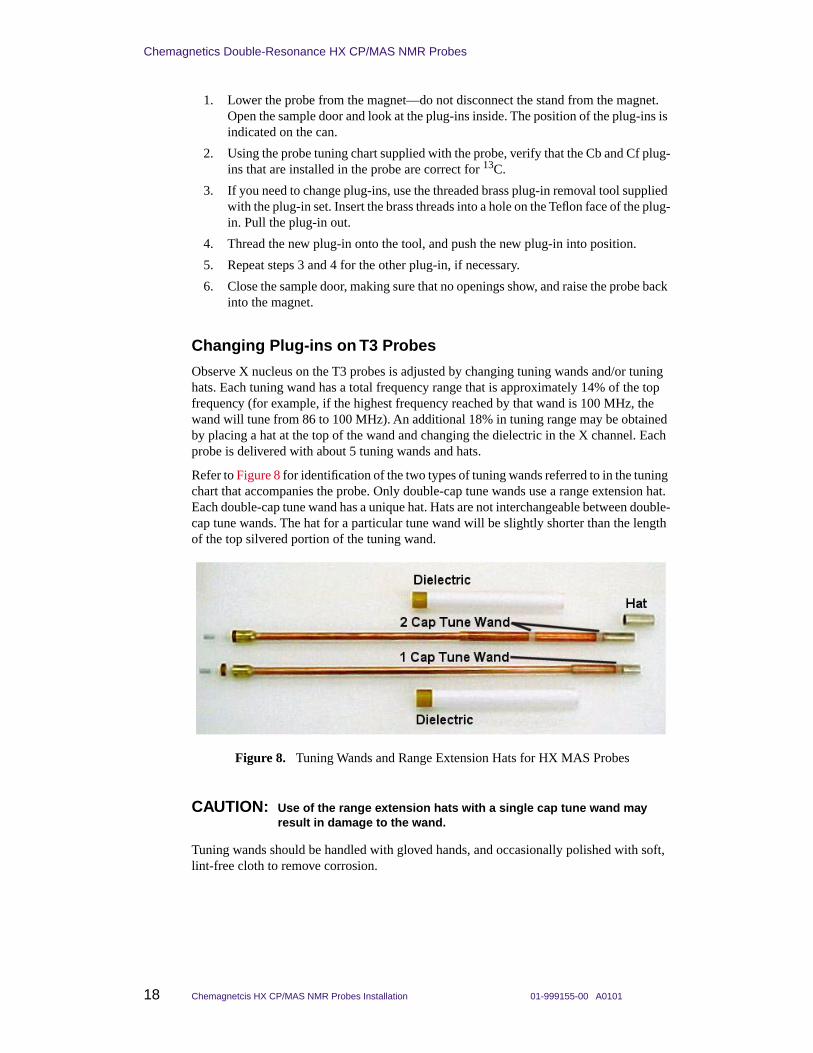
Refer to Figure 8 for identification of the two types of tuning wands referred to in the tuning chart that accompanies the probe. Only double-cap tune wands use a range extension hat. Each double-cap tune wand has a unique hat. Hats are not interchangeable between double-cap tune wands. The hat for a particular tune wand will be slightly shorter than the length of the top silvered portion of the tuning wand.
CAUTION: Use of the range extension hats with a single cap tune wand may result in damage to the wand.
Tuning wands should be handled with gloved hands, and occasionally polished with soft, lint-free cloth to remove corrosion.
Figure 8. Tuning Wands and Range Extension Hats for HX MAS Probes

01-999155-00 A0101 Chemagnetcis HX CP/MAS NMR Probes Installation 19
Changing Plug-ins on APEX and T3 Probes
Changing the tuning range on the HX probe involves either a straight plug-in replacement or a dielectric replacement.
Straight Plug-In Replacement
To replace a tuning wand and hat with a tuning wand and hat, or to replace a tuning wand and no hat with a tuning wand and no hat, use the following steps.
1. To remove the tuning wand, unscrew the knurled brass nut at the base of the tuning wand and pull out the wand. Make sure the probe is raised up in the magnet. If the tuning wand is too long, the probe may need to be removed from the magnet.
2. If there was a hat on the previous tuning wand, place a hat on the current tuning wand. If no hat was present before, do not put a hat on the current wand. If neither of these conditions is met, follow the procedure below for changing tuning wand and dielectric.
3. Slide the tuning wand back into the probe. Screw the knurled brass nut finger tight. Do not use tools to tighten past finger tight.
Dielectric Replacement
To replace a tuning wand and hat with a tuning wand and no hat, or to replace a tuning wand and no hat with a tuning wand and had, use the following steps. You will remove the tuning mechanism and tuning dielectric from the probe to make the change.
1. To remove the tuning wand, unscrew the knurled brass nut at the base of the tuning wand and pull out the wand. Make sure the probe is raised up in the magnet. If the tuning wand is too long, the probe may need to be removed from the magnet.
2. Place a hat, if desired, on the tuning wand.
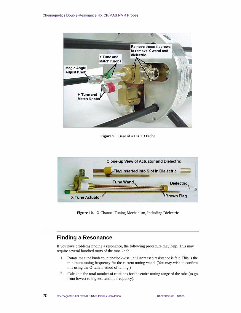
3. Remove the four screws as indicated in Figure 9. Pull on the RF connector and X-tune knob simultaneously to remove the tuning mechanism and tuning dielectric from the probe. When fully withdrawn, you will have parts as shown in Figure 10.
4. Select the proper tuning dielectric for the desired tune wand (see tune chart) and slide the dielectric onto the wand. Next insert the fully assembled tune mechanism (see Figure 10 ) part way into the probe. Before pushing the tune mechanism all the way into the probe, be sure that the brown flag on the X tune actuator engages the slot at the bottom of the tune dielectric (See inset in Figure 10). Slide the tune mechanism back into the probe and replace the screws.
5. Insert the tune wand back into the tune mechanism and tighten the knurled nut finger tight. Do not use tools to tighten.
If the new tuning configuration was chosen to tune the probe to a higher frequency than previously (i.e., going from 15N to 13C), you might need to rotate the tune knob counter-clockwise a variable number of turns before the tuning begins to respond to the changes (possibly as many as 120 turns).
To Replace a: With a: Go to:
tuning wand with hat tuning wand with hat Straight Replacement
tuning wand with no hat tuning wand with no hat Straight Replacement
tuning wand with no hat tuning wand with hat Dielectric Replacement
tuning wand with hat tuning wand with no hat Dielectric Replacement
Chemagnetics Double-Resonance HX CP/MAS NMR Probes
20 Chemagnetcis HX CP/MAS NMR Probes Installation 01-999155-00 A0101
Finding a ResonanceIf you have problems finding a resonance, the following procedure may help. This may require several hundred turns of the tune knob.
1. Rotate the tune knob counter-clockwise until increased resistance is felt. This is the minimum tuning frequency for the current tuning wand. (You may wish to confirm this using the Q-tune method of tuning.)
2. Calculate the total number of rotations for the entire tuning range of the tube (to go from lowest to highest tunable frequency).
Figure 9. Base of a HX T3 Probe
Figure 10. X Channel Tuning Mechanism, Including Dielectric

01-999155-00 A0101 Chemagnetcis HX CP/MAS NMR Probes Installation 21
Tuning MAS Probes
Total Rotations = length in inches of tune tube (from tuning chart) / 0.031.
3. Calculate the Required Rotations to go from the minimum tunable frequency to the frequency desired.
Required Rotations = Total Rotations * minimum frequency / desired frequency.
4. Turn the TUNE knob the Required Rotations clockwise to approximate the desired tune frequency.
5. Turn the MATCH knob in either direction, and observe the result using the Q-tune method of tuning described in the next section of this manual to produce a resonant dip.
Tuning MAS ProbesVarian Chemagnetics double-resonance HX MAS probes are tuned with variable capacitors using knobs at the bottom of the probe. The probe has two variable capacitor knobs each (tune and match) for the decoupler and the observe channel.
CAUTION: The magic angle can be inadvertently misadjusted during probe tuning. Do not turn the chrome magic angle adjust knob while tuning the probe.
APEX MAS Probes Tuning Knobs• 1H tune and match are adjusted interactively by turning two red knobs labeled TUNE
and MATCH.
• X tune and match are adjusted interactively by turning two green knobs labeled TUNE and MATCH.
T3 MAS Probes Tuning Knobs• 1H tune and match are adjusted interactively by turning two red knobs labeled TUNE
and MATCH.
• X tune and match are adjusted interactively by turning a green knob labeled TUNE and a silver knob, which is match, next to the TUNE knob (see Figure 9).
Tuning MAS Probes with Infinityplus
The first sample to be used in the following tests will be the adamantane sample (or adamantane + KBr sample). After verifying proper spinning, stop the spinning, lower the probe from the magnet, and insert this sample into the probe now, prior to tuning. Probes should be shipped configured for tuning 1H/13C. If the probe is not configured for 1H/13C, insert the appropriate plug-ins before proceeding with this procedure.
CAUTION: Do not mistakenly turn the Magic Angle adjust knob, which is silver in color, and set apart from the TUNE and MATCH knobs on both T3 and APEX probes. See Figure 9 (T3 probe).
The Infinityplus console provides three mechanisms for probe tuning:
• Q-type tuning through the tune interface (QTUNE),

Chemagnetics Double-Resonance HX CP/MAS NMR Probes
22 Chemagnetcis HX CP/MAS NMR Probes Installation 01-999155-00 A0101
• High-power reflected power tuning, through the directional couplers and into the tune interface (TUNE_RP), and
• CW reflected power tuning, through the tune interface (TUNE_CW).
The QTUNE method allows you to observe the position and shape (quality) of the probe tuning on the computer screen. The high-power (TUNE_RP) reflected power method using directional couplers allows you to measure forward and reflected power under high-power conditions. Using QTUNE is generally recommended for large tuning changes, such as when changing nuclei. Most users perform final, precise tuning for each sample using the reflected-power method. The low-power reflected power tuning method (TUNE_CW) may be convenient for those customers used to tuning on other Varian spectrometers, but there are some disadvantages.
The different methods of tuning usually lead to the same NMR performance, but they lead to slightly different tuning conditions. It is therefore important to consistently use one method or the other for final tuning on each sample.
• Method 1: Approximate QTUNE when the probe is initially inserted into the magnet and to change nuclei, followed by high-power, reflected-power tuning, (TUNE_RP), for each sample.
• Method 2: Precise QTUNE when the probe is initially inserted into the magnet, to change nuclei, and each time a sample is changed.
• Method 3: Approximate QTUNE when the probe is initially inserted into the magnet and to change nuclei, followed by CW reflected power tuning for each sample.
The default bandwidth of QTUNE is 10 MHz (± 5 MHz). The bandwidth of some probe plug-ins is larger than 10 MHz. If you initially have trouble seeing a resonance with QTUNE, try changing bw while running QTUNE to cover the range of the probe plug-in. Often, a small, poorly matched (shallow) dip can be found and brought into range. Adjusting match first can help in identifying the probe resonance. When bw is increased, you will notice an oscillation in intensity with a period of about 8–10 MHz, and amplitude of about 50% of maximum intensity. These are not resonances, but rather differences in intensity output at different frequencies. A resonance dip is sharp relative to these intensity oscillations.
Tuning with QTUNE
The most common use for QTUNE is to approximately set tuning during initial setup of the probe, or when changing nuclei. Then the final, precise tuning is typically performed on each sample using reflected power.
1. Make sure that the probe/magnet leg interface is cabled as described in Connecting Pneumatics, page 11 and Connecting RF Cables on an Infinityplus, page 13.
2. Check to make sure that the proper black BNC cables are attached to each directional coupler. These cables are labeled “channel 1", “channel 2", etc.
3. Make sure that the arrow on each directional coupler points away from the probe (for reflected power).
4. Run the QTUNE macro from the Experiments menu.
Click on the Experiments menu. If QTUNE does not appear in the menu, Click once on Other… If QTUNE does not appear, click on the System_Dir button at the bottom. Double-click on QTUNE to execute the macro.
5. Follow the instructions in the macro, entering the proton frequency, if requested.
6. Set ch1=2 in the acquisition panel.
01-999155-00 A0101 Chemagnetcis HX CP/MAS NMR Probes Installation 23
Tuning MAS Probes
7. Click on RS and Process to activate the tuning routine. Processing should only include magnitude correct.
8. Tune the H channel of the probe by adjusting the TUNE and MATCH interactively until a deep dip is observed on the screen, centered in the window, and reaching down to the baseline.
Note: The 1H channel can only be tuned using QTUNE if the channel is fullband. Some Infinityplus spectrometers are not fullband on the 1H channel.
9. Click STOP to stop the experiment.
10. Set ch1=1 in the acquisition panel, and make sure that sf1 is correct for the X nucleus on your machine.
Run the NUCL macro in the Utilities menu, if necessary, to set sf1 (the NUCL macro assumes that sf2 is set correctly for 1H.)
11. Start acquisition with RS and Process, and adjust TUNE and MATCH for the X channel interactively until a deep dip is observed on the screen, centered in the window, and reaching down to the baseline.
12. Click STOP to stop the experiment.
13. The probe is now tuned.
• If you plan to tune each sample by this method, you can stop.
• If you plan to tune each sample using reflected power, then you should finish tuning by using either TUNE_RP or TUNE_CW.
Tuning with High-Power Reflected-Power (TUNE_RP)
Final, precise tuning is performed on each sample using high-power reflected power.
The default amplitude and scalar values (aX and scX) set the power level for tuning in this experiment. These values are set low by default to be safe for any probe. Once your probe is calibrated, and safe amplitude and scalar values are known for each channel, the values may be increased for this tuning experiment.
1. Make sure that black BNC tune cables are connected to the directional couplers. Turn the arrows on the directional couplers to point away from the probe.
2. Run the TUNE_RP macro from the Experiments menu.
Click on the Experiments menu. If TUNE_RP does not appear in the menu, Click once on Other… If TUNE_RP does not appear, click on the “System_Dir” button at the bottom. Double-click on TUNE_RP to execute the macro.
3. Follow instructions in the macro, entering the proton frequency, if requested. Set sf2 to the desired proton frequency, and set ch1=2.
4. Click on Repeat Scan to start pulsing.
5. Tune the H channel of the probe by adjusting the TUNE and MATCH interactively until minimum reflected power is displayed on the magnet-leg tune meter. You should be able to obtain a minimum reflected power reading 2 and 4.
The reflected power is also displayed in the active viewport in Spinsight. At the start of tuning, the reflected power will probably be much larger than the voltage range of the digitizer – producing a clipped signal. As reflected power approaches a minimum on the magnet-leg tune meter, the signal displayed in the Spinsight viewport will be within the digitizer limits. Often, the level of this signal is more sensitive than the number display on the magnet-leg tune meter for the final bit of tuning.

Chemagnetics Double-Resonance HX CP/MAS NMR Probes
24 Chemagnetcis HX CP/MAS NMR Probes Installation 01-999155-00 A0101
Once minimum reflected power is obtained, the forward:reflected power ratio may be obtained. Record the number shown for reflected power. Turn the arrow on the 1H directional coupler to point towards the probe; the number displayed on the tune meter now represents forward power. Remember to turn the arrow on the coupler back to its original position pointing away from the probe. Forward: reflected ratio must be at least 10:1, and preferably much higher.
6. Click STOP to stop the experiment.
7. Set ch1=1, and set sf1 to the desired frequency for the X nucleus. Start acquisition with Repeat Scan, and adjust TUNE and MATCH for the X channel interactively until minimum reflected power is displayed on the magnet-leg tune meter. You should be able to obtain a minimum reflected power reading between 2 and 4.
8. Click STOP to stop the experiment.
9. Your probe is now tuned.
CW Reflected-Power Tuning (TUNE_CW)
Final, precise tuning is performed on each sample using CW reflected power. This method is not generally recommended for two reasons.
• Reconnecting cables is required each time tuning is performed.
• Tuning is based on reflected power, but the power used is very low.
However, those familiar with tuning on other Varian instruments may be comfortable with this method, and it is reliable.
1. Attach the H port of the probe to the Tune Interface (J5321) via a BNC cable and BNC-to-N type adaptor.
2. Run the TUNE_CW macro from the Experiments menu.
Click on the Experiments menu. If TUNE_CW does not appear in the menu, Click once on Other… If TUNE_CW does not appear, click on the “System_Dir” button at the bottom. Double-click on TUNE_CW to execute the macro.
3. Follow instructions in the macro, entering the proton frequency, if requested. Set sf1 to the desired proton frequency.
4. Click on Repeat Scan to start the tuning program.
5. Tune the H channel of the probe by adjusting the H-channel TUNE and MATCH interactively until minimum reflected power is observed on the Tune Meter. Click on STOP to stop the experiment.
6. Reattach the probe to its N-type probe cable when done.
7. Repeat steps 1–6 for the X channel of the probe, connecting the X probe cable to the Tune Interface connector. Set sf1 to the desired frequency for 13C. Start the tuning program with Repeat Scan, and adjust the X-channel TUNE and MATCH interactively. Replace the X probe cable to J5311.
Solids AmplifiersSeveral different amplifier configurations are available for solids. For each amplifier configuration, you must limit the input pulse power to avoid damaging the probe with excessive power.

01-999155-00 A0101 Chemagnetcis HX CP/MAS NMR Probes Installation 25
Setting Initial Input Pulse Power for Probes
Solids Amplifiers for Infinityplus
The Infinityplus console can be equipped with several different amplifier options for solids. The proton amplifier consists of a 50 to 100 W AMT driver chassis in the console, and a 500 to 1000 W high-power CMA amplifier, depending on 1H frequency. The lowband amplifier is a 1000-W AMT amplifier covering a frequency range of either 10–130 MHz or 6–220 MHz (or another option at 800 MHz).
WARNING: Shock hazard can result in death or serious injury. Disable Spinsight with the STANDBY button in the Display icon bar whenever opening the probe or connecting cables. Disabling the acquisition process in Spinsight limits the possibility of accidental discharge of current or RF while working with the probe. Remember to click the ENABLE button when you wish to resume operation.
The Varian/ Chemagnetics 500 to 1000-W CMA highband amplifier can be operated in Class C or Class AB (linear) mode. Class AB mode is recommended for CP/MAS. Class C mode is used for proton multiple pulse experiments.
Setting Initial Input Pulse Power for ProbesInput pulse power is controlled by amplitude and scalar parameters.
Amplitude Parameters
Linear amplitude modulators in each transmitter also provide power control. The linear modulators are controlled by the amplitude parameters, which can be assigned values of 0.0 to 1.0. Amplitude parameters are named a(n), for example: aX and aXcp (X channel amplitudes) and aH and aHdec (1H channel amplitudes).
Scalar Parameters
A set of attenuators (79-dB total range) on the output of the transmitter allow you to set the maximum power. The attenuators are software-controlled by the scalar parameters, which can be assigned values of 0.001 to 1.0. Scalar parameters have names such as sc(n), for example: scX (X channel) and scH (1H channel).
Be sure to set the amplitude and scalar values to provide safe power levels to the probe:
• For CP/MAS probes, set aX=0.5 and scX=0.3 for the X channel; set aH=0.5 and scH=0.3 for the 1H channel. These are starting values. You can then increase the power to find a reasonable pulse width.
• If you have a power meter, you may adjust the initial amplitude and scalar values to produce power levels given for this particular probe, if available. Do not rely on oscilloscope voltage measurements to calculate power unless your oscilloscope is properly calibrated for the frequencies that you are using.
• The exact values should be determined during the probe calibration.
Maximum Decoupling Times at Specified 90° Pulse Width Power
Table 5 lists the maximum decoupling times at specified 90° pulse width power values. When running multiple channel experiments, the duty cycle for any single channel must not exceed 3%.

Chemagnetics Double-Resonance HX CP/MAS NMR Probes
26 Chemagnetcis HX CP/MAS NMR Probes Installation 01-999155-00 A0101
Testing MAS ProbesThis section contains test and calibration procedures for the MAS probes. Table 6 lists the test order, samples, and parameter sets.
Specifications for this particular Double-Resonance HX MAS probes are given on the probe installation sheet, which was delivered with the probe.
Note: For rotor sizes 5-mm and larger, you can use a sample that is 50% KBr + 50% adamantane to position the probe, set the magic angle, measure homogeneity, measure decoupler power, and measure carbon pulse width. Use individual samples of 100% KBr and 100% adamantane for 4.0-, 3.2-, and 2.5-mm rotors.
Description of the Pulse Sequences and Parameters
All MAS probe tests use four pulse sequences: 1pncyc, 1pncycH, 1pda, and cp.
The X-channel power is determined by the following parameters:
• aX (1pncyc and 1pda), aXcp (cp) – linear amplitude modulator setting
• scX – attenuator (scalar) setting
Table 5. Maximum Decoupling Times
Proton Frequency Max 1H Irradiation Time Max Duty Cycle
200 MHz 100.0 ms 3%
300 MHz 66.7 ms 3%
400 MHz 50.0 ms 3%
500 MHz 40.0 ms 3%
600 MHz 33.3 ms 3%
Table 6. MAS Probe Test Order, Samples, and Parameter Sets
NMR Tests SamplesTest Parameters in /vnmr/tests
Positioning the Probe in the Magnet, page 28 KBr (+ adamantane) kbr.par
Adjusting the Magic Angle, page 30 KBr (+ adamantane) kbr.par
Calibrating the 1H 90° Pulse Width, page 31 adamantane (+ KBr) masH1.par
Calibrating the 13C 90° Pulse Width, page 32 adamantane (+ KBr) masC13.par
Adjusting the Homogeneity, page 33 adamantane (+ KBr) masC13.par
Adjusting the Hartmann-Hahn Match, page 34 HMB hmb.par
Measuring Signal-to-Noise, page 35 HMB hmb.par
Measuring Decoupler Isolation, page 36 HMB hmb.par
Measuring 31P and 15N 90° Pulse Widths, page 37 31P – Chiraphos15N– 15N glycine
masP31.parmasN15.par

01-999155-00 A0101 Chemagnetcis HX CP/MAS NMR Probes Installation 27
Testing MAS Probes
The proton power is determined by the following parameters:
• aH – linear amplitude modulator setting during 90º pulse
• aHcp – linear amplitude modulator setting during the Hartmann-Hahn match
• aHdec – linear amplitude modulator setting during decoupling
• scH – attenuator (scalar) setting
The pulse width is pw90X (pw90H in cp and 1pncycH). The parameter ct is the Hartmann-Hahn contact time during cross polarization.
Best practice is to set scX and scH to constant values such that the amplitude values, a(n), are set mid-range – around 0.3 – 0.7. Use the linear amplitude modulator settings (aX, aH) to calibrate the precise value of the 13C 90º pulse width and 1H 90º pulse width, and aXcp to match the Hartmann-Hahn condition.
Standard Data Sets
The standard data sets are provided as an easy way to call experiments. Each time a standard data set is called, you should carefully set parameters before proceeding to acquire data.
CAUTION: The probe can be damaged when used with the 1-kW amplifiers. Be sure that you start with a(n) and sc(n) set low. Settings of a(n)=0.5 and sc(n)=0.3 are generally safe to start as long as the amplifiers have been properly padded to put out 1kW at maximum modulator and attenuator settings.
You should save standard data sets for this particular probe as you go, either in ~systest/data/std_files, or in a similar directory in the account in which you are operating. Recommendations to save standard data for this probe are made at several points in the following procedures. You may also wish to print copies of the standard spectra that you collect.
Note: You can only save data in subdirectories of the account in which you are running, but you may open data from any account.
Standard data sets are stored in ~/systest/data/std_files. To open standard data sets, follow one of the following procedures:
If running in the account systest:
1. Click on the menu File, then on Open.
2. Enter a name in the Buffer field. The name must start with a letter. Usually, people use buffer names that indicate the experiment – i.e., cp or c13 – or names that indicate viewport – i.e., a,b,c,d.
3. Double click on the directory std_files.
4. Double click on the appropriate file name to open.
If running in another account, either:
1. Click on the menu File, then on Open.
2. Double click on ..<Parent>. Double click on ..<Parent> again.
3. Double click on systest. Double click on data. Double click on std_files.
4. Enter a name in the Buffer field. The name must start with a letter. Usually, people use buffer names that indicate the experiment – i.e., cp or c13.
5. Double click on the appropriate file name.

Chemagnetics Double-Resonance HX CP/MAS NMR Probes
28 Chemagnetcis HX CP/MAS NMR Probes Installation 01-999155-00 A0101
If standard data sets can not be found, they may be downloaded from the FTP site, ftp.nmr.varianinc.com.
1. Log into systest, and enter cd data.
2. On the FTP site, go to the pub/chemagnetics/InfinityPlus/data directory.
3. Get the file std_files.tar.
4. Exit FTP. Enter tar xvf std_files.tar. Enter rm std_files.tar.
Positioning the Probe in the Magnet
The probe is positioned at the field center by finding the position at which a change in the Z1 shim does not affect the peak position of the sample. The 79Br signal of KBr can be used for probe positioning. Widebore magnet dimensions vary and the approximate field center for an individual magnet is best obtained from the factory if needed. In general though, one can guess and then find the correct position with the following procedure.
Positioning the Probe in the Magnet for Infinityplus
1. Insert the sample of KBr or 50% KBr/Adamantane in the probe. Raise the probe to the approximate operating position. Adjust the upper VT stack if it is in the way. Hold the upper stack in place by tightening the white plastic bolt on the upper stack flange.
2. Spin the sample at 3.0 to 5.0 kHz.
3. Open the standard data set systest/data/std_files/KBr. Refer to Standard Data Sets, page 27.
4. Set sf1 to the correct frequency for 79Br. If you do not know this frequency, then set sf2 to the correct frequency for 1H, and run the macro NUCL under the menu Utilities, entering 79 in the nucleus field.
5. Set aX and scX to safe values for this probe. See “Setting Input Pulse Power for Probes” above.
6. Adjust the tuning of the X channel of the probe for 79Br (see Tuning MAS Probes, page 21, above. If probe was just tuned for 13C, you may skip this step.)
7. Set pw90X to a value from 3.0 to 7.0 µs, set na=1.
It might be necessary to do an array of pw90X to determine the 79Br 90° pulse width if signal-to-noise is inadequate. This parameter set will be used for the magic angle adjustment.
8. Click on Acquire and Process to take an FID and process it. Processing should be set to DC OFFSET, FT, Phase…buffers last values, DC OFFSET, Auto display.
• Processing functions are off when the little box to the left of the function is teal. A Processing function is turned on when the little box to the left of the function is red.
• To phase, press Alt-H or click on Phasing… under the Analysis menu.
• Gain is not set automatically on Infinityplus spectrometers. The acquisition parameter rg controls the gain setting. If your spectrum can not be phased, especially if the large main peak looks like it sits in a hole (peak in a pit), then the gain may be set too high. Click the reread button on the display panel. Then

01-999155-00 A0101 Chemagnetcis HX CP/MAS NMR Probes Installation 29
Testing MAS Probes
type Alt-B (hold down the Alt and B keys at the same time) to display both Real and Imaginary parts of the data. Press Alt-G to display the digitizer limits. If the FID from a single acquisition extends right to the digitizer limits, then the gain must be reduced.
9. Click on Setup menu –>Set Observe Frequency. Click once on the central tall line to move the peak on resonance.
10. Acquire and process another spectrum. Phase the spectrum and zoom the display around the central peak by clicking on Expand in the Display icon bar and then clicking once to the left and once to the right of the peak.
11. Open the shim controller panel. If the accessories panel is already open, proceed to step d below.
a. Under the File menu, select Shell.
b. In the xterm window that appears, type acc& at the prompt. This brings up the accessory controller panel to the right of the Spinsight window.
c. Minimize or lower the xterm window (not the accessory controller panel).
d. In the accessory controller panel, click on Shim to open the Shim Controller panel.
12. In the Shim Controller panel, click on the File menu and select Load Data. If you see a file called zero.shim, double click on it to open and skip to step 14. If not, close the window and proceed with step 13.
13. Using the Shim Controller Panel, set all shims to zero by clicking + and – buttons next to the shim you want to change.
You can toggle between increments of 1, 5, 10, 50, 100, 500 and 1000 for each shim by selecting the desired increment from a pull-down menu. A button next to each shim displays the current increment and activates the pull-down menu.
When all shims are zero (be sure to check all shim groupings listed under the Manual menu), store the settings to a file called zero.shim.
a. In the Shim Controller panel, click on the File menu and select Store Data.
b. Type in the filename zero.shim.
c. Click on OK.
14. Acquire and process; reposition the display if necessary.
15. Measure the gap between the bottom of the shim flange and the top of the probe base. Record this value.
16. Change the Z1 shim to +20,000 (or large positive value). Acquire and process a spectrum. The peak will probably shift left or right. Note the position of the peak (in kHz or ppm – absolute referencing is not important) by clicking and holding the left mouse button and reading the position from the pop-up window.
• If the “peak” is a complex pattern or an asymmetric line, visually estimate the center of gravity (first moment) of the signal and use that value for peak position.
• If the Shim Controller panel disappears behind the Spinsight window while working in Spinsight, double click on the Shim icon in the Accessories panel to bring back to the front (single click to close plus one more click to re-open).
17. Change the Z1 shim to –20,000 (or large negative value). Acquire and process a spectrum and note the position of the peak.

Chemagnetics Double-Resonance HX CP/MAS NMR Probes
30 Chemagnetcis HX CP/MAS NMR Probes Installation 01-999155-00 A0101
18. Reposition the probe up or down. You may need to move the VT stack. Repeat step 15 to step 17 and continue adjusting the probe position until the Z1 shim does not change the peak position.
19. Record the final vertical position of the probe in the probe installation sheet. Tighten the upper probe stop to maintain the probe in the correct position when inserted. Close the Shim Controller panel (single click on Shim icon in Accessories panel). Reposition the VT stack so that if correctly mates to the top of the probe.
Adjusting the Magic Angle
The magic angle (54.7°) is the angle between the MAS rotor and the vertical field direction. This angle is set in the factory but requires frequent adjustment in the field.
The angle should be set:
• when the probe is installed after not be used for a while
• every few days during continuing operation
• if the HMB linewidth is suspiciously large (see Setting the Hartmann-Hahn Match)
Figure 11 and Figure 12 show FID displays of KBr on and off angle.
1. Zero the shims. Obtain a KBr spectrum.
Figure 11. FID Display of KBr On-Angle
Figure 12. FID Display of KBr 1/2 Turn Off-Angle
01-999155-00 A0101 Chemagnetcis HX CP/MAS NMR Probes Installation 31
Testing MAS Probes
2. Under the Setup menu, select Set Observe Frequency and click on the peak to move it on resonance.
3. Acquire another FID, this time clicking on Acquire. Press Alt-B to display both the real and imaginary channels (or select Both from the Real/Imag option under the Display menu).
4. Phase the FID so that all of the signal is positive and in the real channel.
5. Press Alt-D to open the Process panel (or click on Process Panel in the Panel menu). Turn off all processing functions except Phase…Buffers Last Values and Auto Display.
6. Click RS and Process to begin acquiring data repetitively and phasing prior to display. Press Alt-R to display only the Real data. The FID should look like Figure 11 or Figure 12.
7. Adjust the magic angle by turning the chrome-colored knob on the bottom of the probe. Observe the signal continuously and adjust in 1/8-turn steps until the FID is similar to Figure 11 (where the “spikes” on the FID are visible until the signal has decayed).
Maximize the intensity and number of spikes in the picket-fence pattern. When the magic angle is adjusted correctly the spikes should disappear just as the overall decay disappears into the baseline. The angle is now adjusted.
8. Optional: Save a standard file of the KBr FID. Suggested directory: ~/data/std_files. Suggested filename: KBr.serial_number(e.g., KBr.7024). You can also print a copy of this FID.
Calibrating the 1H 90° Pulse Width
The 1H channel is calibrated using the 50% KBr/adamantane sample. The specification for the decoupler is the 1H 90° pulse width. The 1H field strength, γB2 = 1.0/(4.0*pw90). 1H pulse width specifications is listed on the probe installation sheet that came with your probe.
1. Insert the 50% KBr/Adamantane sample or adamantane-only and set the rotor speed to 5.0 kHz (3.5 kHz for 9.5mm rotors).
2. Open the standard data set systest/data/std_files/adam.1H.
3. Tune both the 1H and 13C channels of the probe for this sample— you will be using the 13C channel in later experiments. Refer to Tuning MAS Probes, page 21.
4. Acquire and process a 1H spectrum of adamantane.
Processing should include DC Offset, Back LP Good—5 pts, Exponential broadening=20 Hz, Complex FT=8096, Phase—Use buffers last values, DC Offset.
Phase the spectrum. Place the transmitter on resonance by selecting Set Observe Frequency from the Setup menu and clicking on the tallest peak, and repeat the acquisition, process and phase. Record the value of sf2 for the spectrum on resonance.
5. Array pw90H to calibrate the 1H 90° pulse width. Start with values of aH and scH that should produce a 90° pulse width greater than the specified value and increase them until the specification is obtained.
True 90° pulse width =1/2 (time for 360° null – time for the 180° null)

Chemagnetics Double-Resonance HX CP/MAS NMR Probes
32 Chemagnetcis HX CP/MAS NMR Probes Installation 01-999155-00 A0101
This value might be less than the pulse width used to obtain maximum intensity due to rf inhomogeneity of the coil, and non-ideality of the rf pulse.
Some double-resonance MAS probes have substantial proton background. The adamantane resonance sits on top of a broad line that increases in intensity monotonically with pulse width. Linear prediction may be used to back predict (replace) the first n points of the FID to eliminate probe background from the spectrum. See processing in step 4 above. If linear prediction is not used when a large probe background is present, pulse width measurements will not be accurate.
6. Record the value of aH and scH needed to obtain the specified 1H 90° pulse width. These values provide the upper limits on aH, aHdec, aHcp, (=aH), and scH (=scH) that should not be exceeded during subsequent calibration of cross polarization.
7. Optional: Acquire and save a standard data file of the 1H adamantane FID with sf2 set to on resonance, pw90H set to the measured 1H 90° pulse width, and aH and scH set accordingly for that pulse width. Suggested directory: ~/data/std_files. Suggested filename: adam.1H.serial_number.
Calibrating the 13C 90° Pulse Width
The 13C 90° pulse width is calibrated using the 50% KBr/adamantane sample or adamantane sample. The specification for the lowband channel is the 13C 90° pulse width. 13C pulse width specifications is listed on the probe installation sheet that came with your probe.
1. If not already done, insert the 50% KBr/adamantane (or adamantane) sample and set the rotor speed to 5.0 kHz (3.5 kHz for 9.5-mm rotors). Tune both the 1H and 13C channels of the probe for this sample.
2. Open the standard data set systest/data/std_files/adam.13C.
3. Set aX and scX to safe values (aX=0.5 and scX=0.3 if you do not already know some safe values). Set al=1024. Set aHdec=[amplitude for 1H pulse width measured above]. Set scH=[scalar measured for 1H pulse width above]. Set sf2= [on resonance for 1H], set in step 4 above.
4. Acquire and process a spectrum.
Processing should include DC OFFSET, apodize>exponential=10, FT, Phase… buffers last values, DC OFFSET, Auto display).
5. Position the transmitter between the two adamantane resonances. Acquire, process, and rephase.
6. Array pw90X to calibrate the 13C 90° pulse width. Start with a value of aX that should produce a 13C 90° pulse width greater than the specified value and increase aX (and scX as necessary) until the specification is obtained.
True 13C 90° pulse width = 1/2 (time for 360° null – time for the 180° null)
7. This value may be less than the pulse width used to obtain maximum intensity due to rf inhomogeneity of the coil.
8. Record the values of aX and scX needed to obtain the specified 13C 90° pulse width. These values determine the 13C power used during cross polarization, except for ceramic modules. For ceramic modules, repeat the 13C 90° calibration to obtain

01-999155-00 A0101 Chemagnetcis HX CP/MAS NMR Probes Installation 33
Testing MAS Probes
values of aX and scX that are needed to obtain the 13C 90° pulse width equal to the specified 1H 90° pulse width.
Adjusting the Homogeneity
Use the 50% KBr/adamantane sample or adamantane sample for the homogeneity adjustment. Be sure that the sample is well packed, with no vortex. Check the 50% KBr/adamantane sample periodically to ensure that no vortex is present. A vortex is a small hole in the center of the sample due to incomplete packing. Adamantane evaporates from the solid state over time and leaves a vortex. Repack the sample if a vortex is present. Figure 13 shows a typical MAS spectrum of adamantane.
1. The 50% KBr/adamantane sample or adamantane sample should already be in place and spinning at 5.0 kHz (3.5 kHz for 2.5-mm rotors), and the probe should be tuned for 1H and 13C. If not, load the sample, and repeat the 1H and 13C PW90 calibrations.
2. Using the parameters and experiment from the previous section (Calibrating the 13C pulse width) obtain a 13C spectrum. Set attdec=1/2, its previous value.
3. Increase the number or data points, al, to a value necessary to avoid truncation of the adamantane FID. The value of al can be set as high as 5000 (aqtm=500 ms) when low values of aHdec and scH are used. In the processing panel, turn off apodization. Set FT size to 32768 (32K).
CAUTION: The probe and 1H amplifier can be damaged with a large aHdec value and long acquisition time. Reduce the value of aHdec by one half to one third of the 1H specification level for adamantane shimming.
4. Begin repetitive mode acquisition by clicking on Repeat Scan and Process. Open the Shim panel and adjust shims to increase the peak height.
5. A typical procedure is to first adjust Z1, Z2, X and Y. Additional improvement can be obtained with XZ, YZ, XY, X2Y2, XZ2, and YZ2. Usually other shims have little affect. The specification for adamantane line width for all MAS probes is 0.1 ppm,
Figure 13. Typical MAS Spectrum of Adamantane
lb=1.0at=0.2

Chemagnetics Double-Resonance HX CP/MAS NMR Probes
34 Chemagnetcis HX CP/MAS NMR Probes Installation 01-999155-00 A0101
at half height, as shown in Figure 13. Although line shape specification is only given for the peak at half height, it is expected that the line obtained to demonstrate specification will be a nice Lorentzian shape, i.e., no large feet or shoulders.
6. Save the shim file; suggested name is probe_serial_number.shim. Close the Shim Controller panel.
7. Optional: Acquire and save a standard data file of the shimmed 13C adamantane FID. Suggested directory: ~/data/std_files. Suggested filename: adam.13C_serial.number (e.g., adam.13C_7014).
Adjusting the Hartmann-Hahn Match
For this adjustment, use the HMB sample and set the rotor speed to 3.3 kHz (5.0 kHz for 2.5-mm rotors) Figure 14 shows a typical Hexamethylbenzene (HMB) spectrum.
1. Insert the HMB sample and set the rotor speed to 3.3 kHz (5.0 kHz for 2.5mm rotors).
2. Open the standard data file systest/data/std_files/hmb.cp.
3. Tune both the 1H and 13C channels of the probe for this sample. This time, now that pulse width is set, try to optimize tuning by adjusting only the TUNE knobs; avoiding changing the MATCH knob.
4. Set na=2 pd=3s ct=1ms.
5. Set aXcp and scX to the values determined in the 13C 90º pulse width calibration.
6. Set aH, aHcp, and aHdec to the value determined for aH in the 1H 90º pulse width calibration. Set scH to the value determined for scH in the 1H 90º pulse width calibration.
7. Acquire and process a spectrum. Processing should be DC, apodize>exponential=10, FT, phase, DC.
Figure 14. Typical Hexamethylbenzene (HMB) Spectrum
Aromatic
Methyl

01-999155-00 A0101 Chemagnetcis HX CP/MAS NMR Probes Installation 35
Testing MAS Probes
Position the transmitter near the low frequency methyl resonance.
8. Acquire, process and rephase the spectrum. The spectrum should look similar to Figure 14.
Set up an array for aXcp starting at the current value of aXcp and stepping down in steps of –0.007 for 40 steps.
To set up an array, click in the aXcp parameter field. Then click the Array button. Enter the size of the array in the #values field and press the Return key. The maximum size is 40. Set the Dimension field to 2. Verify that the initial value of aXcp = [value set for aX in the 13C 90º pulse width calibration]. Enter –0.007 in the Increment field. Click the Apply button. Verify that all values of aXcp are positive. Decrease # values if not. Click the Close button. Note that the aXcp parameter field now has a small asterisk next to it. This indicates that the parameter is arrayed. Make sure that the little box next to the Array button is red (on).
9. Select a value of aXcp from the arrayed data set that yields maximum signal. The maximum signal should be obtained for a value of aXcp just less than that determined for the 13C 90° pulse width (this is matching on the lower sideband).
10. With the new value of aXcp set an array of values of pw90H from 1 µs to at least 4 times the current pw90H.
True 90° pulse width for CP=1/2 (time for 360° null – time for 180° null)
Make a fine adjustment of pw90H for maximum signal. Cross-polarization is now calibrated.
• The 1H 90º pulse width by CP may be less than the 1H 90º pulse width measured in 1H 90º pulse width calibration. This is due to rf inhomogeneity. If there is a large difference between the two pulse widths (more than 0.2 to 0.3 microseconds), it is safest to adjust the aHdec power level down so that aHdec corresponds to the larger, specified 1H 90º pulse. The reason for this is that some of the sample is seeing a higher decoupling power than the original calibration indicated as an average over the sample. This is typically only an issue in large coils, such as 9.5 mm. The new aHdec can be calculated rather than re-calibrated. For example:
aHdec(new) = aHdec(set above) * (1H 90º pulse by CP)/(1H 90º pulse measured in pulse width calibration)
• For routine CP/MAS, matching the Hartmann-Hahn condition corresponding to the specification of the probe is not necessary. Hartmann-Hahn Matching with pw90H set to 4–5.5 µs, and aH, aHcp, and aXcp reduced by corresponding amounts is adequate for most experiments. (Note that for 7.5 and 9.5 mm rotors, this is already at the specified levels.)
Measuring Signal-to-Noise
Signal-to-noise specifications are listed on the probe installation sheet that came with your probe.
1. Use the HMB sample and the same parameters as Adjusting the Hartmann-Hahn Match, page 34.
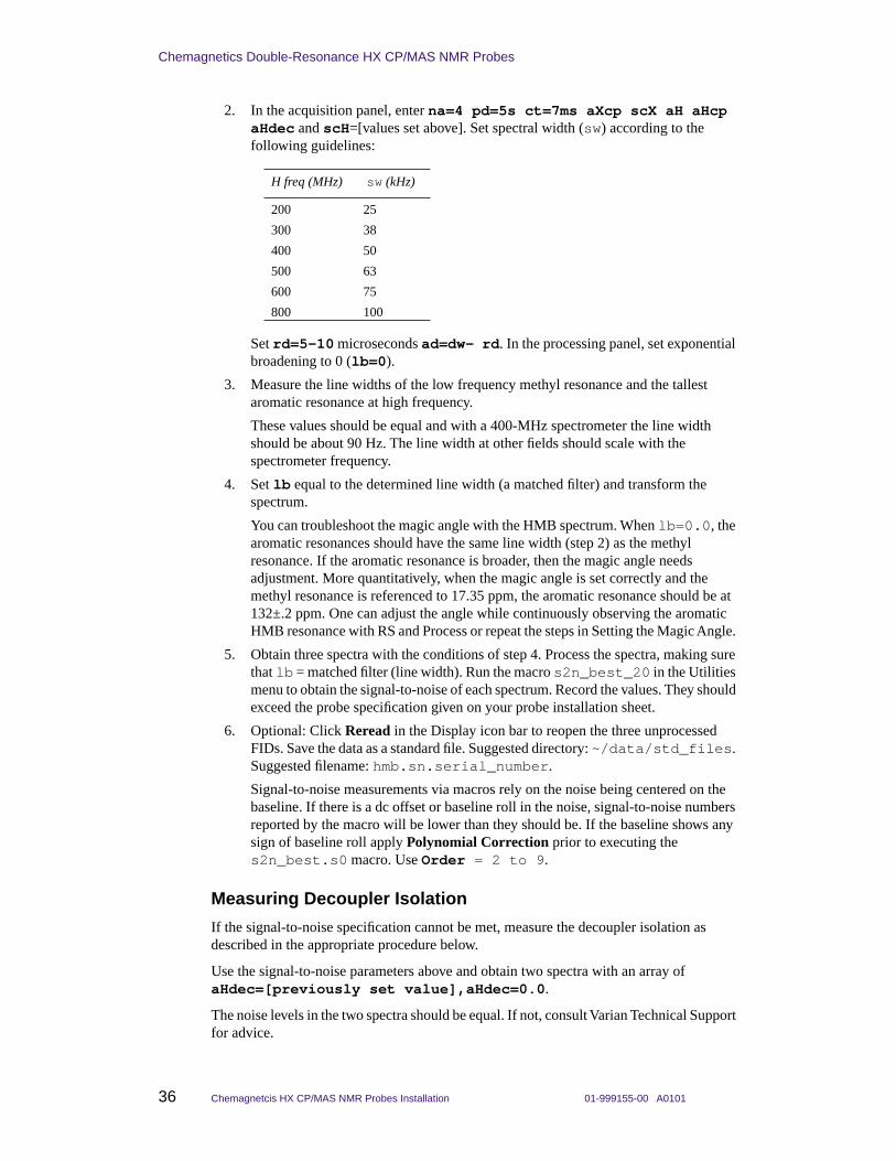
Chemagnetics Double-Resonance HX CP/MAS NMR Probes
36 Chemagnetcis HX CP/MAS NMR Probes Installation 01-999155-00 A0101
2. In the acquisition panel, enter na=4 pd=5s ct=7ms aXcp scX aH aHcp aHdec and scH=[values set above]. Set spectral width (sw) according to the following guidelines:
Set rd=5–10 microseconds ad=dw– rd. In the processing panel, set exponential broadening to 0 (lb=0).
3. Measure the line widths of the low frequency methyl resonance and the tallest aromatic resonance at high frequency.
These values should be equal and with a 400-MHz spectrometer the line width should be about 90 Hz. The line width at other fields should scale with the spectrometer frequency.
4. Set lb equal to the determined line width (a matched filter) and transform the spectrum.
You can troubleshoot the magic angle with the HMB spectrum. When lb=0.0, the aromatic resonances should have the same line width (step 2) as the methyl resonance. If the aromatic resonance is broader, then the magic angle needs adjustment. More quantitatively, when the magic angle is set correctly and the methyl resonance is referenced to 17.35 ppm, the aromatic resonance should be at 132±.2 ppm. One can adjust the angle while continuously observing the aromatic HMB resonance with RS and Process or repeat the steps in Setting the Magic Angle.
5. Obtain three spectra with the conditions of step 4. Process the spectra, making sure that lb = matched filter (line width). Run the macro s2n_best_20 in the Utilities menu to obtain the signal-to-noise of each spectrum. Record the values. They should exceed the probe specification given on your probe installation sheet.
6. Optional: Click Reread in the Display icon bar to reopen the three unprocessed FIDs. Save the data as a standard file. Suggested directory: ~/data/std_files. Suggested filename: hmb.sn.serial_number.
Signal-to-noise measurements via macros rely on the noise being centered on the baseline. If there is a dc offset or baseline roll in the noise, signal-to-noise numbers reported by the macro will be lower than they should be. If the baseline shows any sign of baseline roll apply Polynomial Correction prior to executing the s2n_best.s0 macro. Use Order = 2 to 9.
Measuring Decoupler Isolation
If the signal-to-noise specification cannot be met, measure the decoupler isolation as described in the appropriate procedure below.
Use the signal-to-noise parameters above and obtain two spectra with an array of aHdec=[previously set value],aHdec=0.0.
The noise levels in the two spectra should be equal. If not, consult Varian Technical Support for advice.
H freq (MHz) sw (kHz)
200 25
300 38
400 50
500 63
600 75
800 100

01-999155-00 A0101 Chemagnetcis HX CP/MAS NMR Probes Installation 37
Testing MAS Probes
Measuring 31P and 15N 90° Pulse Widths
This section describes measuring 31P and 15N pulse widths. Most double-resonance MAS probes tune from 15N to 31P. The pulse width specifications for these nuclei establish the upper and lower limits for all pulse widths. For example, if the 15N 90° pulse width is 5 µs, and the 13C 90° pulse width is 3 µs, the 2H pulse width should be about 4 µs.
31P 90° Pulse Width
1. Refer to the probe tuning chart, provided in a booklet with the probe, to determine the appropriate plug-ins for 31P. Insert these into the probe (see Changing Plug-ins on APEX and T3 Probes, page 17).
2. Insert a sample of chiraphos (or ammonium dihydrogen phosphate) sample into the probe and set the rotor speed to 3.0 kHz (5.0 kHz for 2.5 mm probes).
3. Change the quarter-wave cable on the observe preamplifier to that appropriate for 31P. Check the low pass filters on the observe channel to be sure the cutoff is greater than the 31P frequency; the cutoff is correct if the correct filter kit is being used.
4. Open the standard data file ~/systest/data/std_files/chiraphos.31P.
5. Tune the 31P and 1H channels of the probe.
6. Set aX and scX to the levels used for the 13C 90° pulse width calibration. Initially set aX to a value slightly less than that used for the 13C 90° pulse width calibration.
7. Set aHdec, and scH to the final values determined from the “Adjusting the Hartmann-Hahn Match” section.
8. Acquire a spectrum. Process and phase. (Processing = DC OFFSET, FT, Phase, DC). Set the transmitter to the high frequency side of the two resonances. Acquire, process, and phase another spectrum.
9. Array pw90X to calibrate the 31P 90° pulse width. Start with a value of aX that should produce a 90° pulse width larger than the specified value and increase aX until the recommended value is obtained.
The 31P T1 of both chiraphos and ammonium dihydrogen phosphate is very long. You can speed up the pulse width calibration by finding the 360º and 720º nulls instead of the 180º null, which will be distorted by incomplete relaxation. Even if you pulse faster than T1, the 360º and 720º nulls will still be accurate.
• True 90° pulse width = 1/2(time for 360° null - time for 180° null)
• True 90° pulse width = 1/4(time for 720° null - time for 360° null)
This value might differ from the pulse width used to obtain maximum intensity due to rf inhomogeneity of the coil or pulsing faster than T1.
10. Record the values of aX and scX needed to obtain the recommended 31P 90° pulse width.
11. Optional: Save a standard data file. Suggested directory: ~/data/std_files. Suggested filename: chiraphos.31P.serial_number.
12. Optional: You can also calibrate 31P cross-polarization with the procedures described in Adjusting the Hartmann-Hahn Match, page 34.

Chemagnetics Double-Resonance HX CP/MAS NMR Probes
38 Chemagnetcis HX CP/MAS NMR Probes Installation 01-999155-00 A0101
15N 90° Pulse Width
1. Refer to the probe tuning chart, provided in a booklet with the probe, to determine the appropriate plug-ins for 15N. Insert these into the probe (see Changing Plug-ins on APEX and T3 Probes, page 17).
2. Insert the sample of 15N glycine into the probe and set the rotor speed to 3.0 kHz (5.0 kHz for 2.5 mm probes).
3. Change the quarter-wave cable on the observe preamplifier to that appropriate for 15N.
4. Open the standard data file ~/systest/data/std_files/gly.15N_1pda.
5. Tune the 15N and 1H channels of the probe.
6. Set aX and scX to the levels used for the 13C 90° pulse width calibration. Initially set aX to a value slightly less than that used for the 13C 90° pulse width calibration.
7. Set aHdec and scH to the final values determined from Adjusting the Hartmann-Hahn Match, page 34.
8. Acquire, process, and phase a spectrum. (Processing should be DC, Back Predict Good = 6 pts, Apodize>Exponential = 20, FT, Phase, DC.) Set the transmitter near the single 15N resonance. Acquire, process and rephase another spectrum.
9. Array pw90X to calibrate the 15N 90° pulse width. Start with a value of aX that should produce a 90° pulse width greater than the specified value and increase aX until the recommended value is obtained.
True 90° pulse width = 1/2(time for 360° null - time for 180° null). This value might be less than the pulse width used to obtain maximum intensity due to rf inhomogeneity of the coil.
10. Record the values of aX and scX needed to obtain the recommended 15N 90° pulse width.
11. Optional: Save a standard data file. Suggested directory: ~/data/std_files. Suggested filename: gly.15N_1pda_serial_number.
12. Optional: Calibrate 15N cross-polarization with the procedures described in Adjusting the Hartmann-Hahn Match, page 34.
Acoustic ringing often causes considerable baseline roll in single-pulse 15N spectra. Linear back prediction may be necessary to eliminate this roll. Acoustic ringing in cross-polarization is cancelled by the 4 elements of the phase cycle and so is a smaller problem.
Verifying VT Operation (Optional)This test should be performed on a VT-capable MAS probe of the customers choice at instrument installation. Performing this test on each probe is not necessary. The customer must make sure that appropriate cryogens and nitrogen gases are available, and at the required pressures.
VT tests include raising and lowering temperature over the allowed VT range, verifying tuning, and taking representative spectra to check noise level and check that the probe does not arc. At each temperature setting, check to make sure that temperature is regulated to ±1 degree; typically the regulation is better.
Note: If the customer does not supply nitrogen boil-off gas at sufficient pressure (80 psi), it might be impossible to maintain temperature and spin fast at the same time.

01-999155-00 A0101 Chemagnetcis HX CP/MAS NMR Probes Installation 39
Verifying VT Operation (Optional)
See the Solids Temperature Controller manual and Controller Software manual for details on the controller operation if difficulties arise, or for more details concerning operation.
CAUTION: The probe and magnet can be damaged if procedures are not followed carefully. Read the Solids Temperature Controller manual thoroughly before performing VT for the first time.
Preparing for VT Operation
1. Insert the HMB sample. Insert the proper 13C plug-ins into probe. Raise the probe into the magnet.
CAUTION: The probe can be damaged by impure or moist spinning, purge, or VT air. Use dry nitrogen for spinning, purge, and VT gas before proceeding with temperatures above 150°C or below room temperature.
2. Switch the spinning, VT, and purge gas supply to clean, dry nitrogen. Spin the sample to 5.0 kHz (3.0–4.0 kHz for 9.5 mm probes). Make sure that the sample is spinning smoothly before proceeding with VT operation.
3. Set up probe cabling, filters, and observe quarter-wave cable for 13C observe. Tune the probe channels for 13C observe and 1H decoupling.
4. Make sure the VT upper stack is installed as described in Installing the VT Upper Stack, page 11.
5. Make sure that the purge hose is connected to the probe purge nipple. Turn on the purge gas supply and adjust the flow until the purge gas flowmeter indicates 100 standard cubic feet per hour (SCFH).
6. Make sure that both the VT hose and the heater stack sensor cable are connected to the top of the VT upper stack. Turn on the heater gas and adjust the flow until the heater gas flowmeter indicates 100–150 SCFH.
The spinning speed will likely change slightly as the VT flow comes on, but the controller should soon correct the speed.
Put your hand behind the VT exhaust at the top of the solids upper stack. You should feel a good flow of gas coming out of the stack. If you do not feel a reasonable flow coming out, the upper stack and the probe are not mated properly, and VT gas is being dissipated in the magnet bore. If you are not sure whether the flow is appropriate, intentionally disengage the stack by raising it about a centimeter, and feel the flow that comes out of the VT exhaust at the top of the stack. Then engage the stack and feel the flow again. You should notice a difference in the flow.
7. Use the parameters from the 13C signal-to-noise spectrum.
8. Acquire a 13C CP/MAS spectrum at room temperature.
CAUTION: The magnet and probe can be damaged by improper VT gas exhaust. Do NOT continue with VT operation until VT gases are exhausted correctly.
• A flashing display on the VT readout chassis indicates a poor connection between the sensor and the probe. Check both ends of the sensor cable if a temperature reading does not display on the VT controller chassis.
• A safety switch prevents power from being applied to the probe heater when the heater gas flow is less than 80 SCFH.

Chemagnetics Double-Resonance HX CP/MAS NMR Probes
40 Chemagnetcis HX CP/MAS NMR Probes Installation 01-999155-00 A0101
• Any time you are concerned about VT operation, you can select the Reset button from the Controller menu to shut down the heater and reset the controller functions to default settings.
• Signal intensities might be different than those noticed previously because you are now spinning at a different speed. As long as the signal is reasonably strong, continue. If the signal is very weak, find a new Hartmann-Hahn match, which is described in Adjusting the Hartmann-Hahn Match, page 34
Starting Temperature Control Operation (High Temperature)
1. To open the ACC Temperature Controller software, enter acc& in an xterm window. Click the Solid Temp button.
2. Select the Reset button from the Controller menu.
3. Choose the Set Temperature option from the Temperature menu.
• Enter 80.00 into the Target Temperature box.
• Click the OK button.
The temperature begins to climb. Note the spinning speed. It might fluctuate slightly during a temperature change, but the controller should compensate and return the speed to the set point. Spinning should remain smooth throughout.
If the temperature climbs too slowly, click on Select Slew Rate from the Controller menu, and select 20 or 40.
4. After 80°C is achieved, wait about 10 minutes, then tune the 1H and 13C channels of the probe for minimum reflected power. Wait another 5 minutes, verify that tuning is stable. If tuning is not stable, re-tune and wait another 5 minutes.
5. Acquire a CP/MAS spectrum using the parameters from the room temperature spectrum.
The HMB CP/MAS spectra acquired at various temperatures might change in signal-to-noise, but should appear essentially the same. While signal-to-noise changes due to changing CP and relaxation dynamics at various temperatures, the general noise level should remain constant, and no sign of arcing should be observed.
CAUTION: The probe will be damaged if you exceed 80°C on a Kel-F module. If you are testing a probe with a Kel-F module, stop here and proceed with low temperature tests.
6. Set the temperature to 175°C and repeat the probe tuning process.
a. Choose the Set Temperature option from the Temperature menu.
Enter 175.00 into the Target Temperature box.
Click the OK button.
The temperature begins to rise. Note the spinning speed. It might fluctuate slightly during a temperature change, but the controller should compensate and return the speed to the set point. Spinning should remain smooth throughout.
b. After 175°C is achieved, wait about 10 minutes, then tune the 1H and 13C channels of the probe for minimum reflected power. Wait another 5 minutes, verify that tuning is stable. If tuning is not stable, re-tune and wait another 5 minutes.

01-999155-00 A0101 Chemagnetcis HX CP/MAS NMR Probes Installation 41
Verifying VT Operation (Optional)
c. Acquire a CP/MAS spectrum using the parameters from the room temperature spectrum.
The melting point of HMB is 166 to 168°C, so the CP spectrum at 175°C might show signs of melting, including substantial loss of CP signal. This is okay. Note the noise level and tuning stability for acceptable performance.
7. Set the temperature to 250°C and repeat the probe tuning process.
a. Enter 250.00 into the Target Temperature box.
Click the OK button.
The temperature begins to rise. Note the spinning speed. It might fluctuate slightly during a temperature change, but the controller should compensate and return the speed to the set point. Spinning should remain smooth throughout.
b. After 250°C is achieved, wait about 10 minutes, then tune the 1H and 13C channels of the probe for minimum reflected power. Wait another 5 minutes, verify that tuning is stable. If tuning is not stable, re-tune and wait another 5 minutes.
c. Acquire a CP/MAS spectrum using the parameters from the room temperature spectrum.
If achieving 250°C is difficult, reducing the VT flow might be necessary. Make sure the flow stays above 80 SCFH.
The melting point of HMB is 166–168°C, so the final high-temperature spectrum at 250°C will show signs that the HMB had melted, including substantial, or complete loss of CP signal. This is okay. Note the noise level and tuning stability for acceptable performance.
8. Cool down probe and sample.
Set the temperature target to 10C. The heater stops pulsing, and temperature begins to drop. Select the Reset button from the Controller menu to drop the temperature faster.
CAUTION: The probe can be damaged if the gas flow is disconnected too soon. DO NOT disconnect the gas flow to the upper stack until the temperature reading is at essentially room temperature for at least 20 minutes. Leaving the gas flow connected at all times is preferable.
9. When the temperature stabilizes at room temperature, repeat the tuning process. Waiting for complete thermal eqilibration is not necessary; 20 minutes should be enough.
• After room temperature is achieved, wait about 10 minutes, then tune the 1H and 13C channels of the probe for minimum reflected power. Wait another 5 minutes, verify that tuning is stable. If tuning is not stable, re-tune and wait another 5 minutes.
• Acquire a CP/MAS spectrum using the parameters from the room temperature spectrum.
The CP/MAS spectrum might not be perfectly identical to the previous room temperature CP/MAS spectrum due to some residual heat in the probe, but the two results should be very similar. Noise level should be the same, with no sign of arcing.

Chemagnetics Double-Resonance HX CP/MAS NMR Probes
42 Chemagnetcis HX CP/MAS NMR Probes Installation 01-999155-00 A0101
Starting Temperature Control Operation (Low Temperature)
CAUTION: The probe can be damaged by impure or moist spinning, purge, or VT air. Use dry nitrogen for spinning, purge, and VT gas before proceeding with temperatures above 150°C or below room temperature.
1. To open the ACC Temperature Controller software, enter acc& in an xterm window. Click the Solid Temp button.
2. Choose the Set Temperature option from the Temperature menu.
• Enter 10.00 (below room temperature) into the Target Temperature box.
• Click the OK button.
3. Disconnect the VT gas hose from the top of the VT upper stack, and reconnect it to one side of the heat-exchange coil.
4. Connect one end of the insulated transfer line to the other side of the heat exchange coil, and the other end of the insulated transfer line to the top of the VT upper stack.
5. Put the heat exchange coil into the supplied bucket, and fill with liquid nitrogen.
Note that once full, you will need to continue to drizzle liquid nitrogen into the bucket to keep it full during operation.
If the level of liquid nitrogen drops significantly in the bucket, VT performance will suffer. A low temperature might not be maintained if liquid nitrogen level is too low, or temperature will fluctuate greatly.
6. Choose the Set Temperature option from the Temperature menu.
• Enter –80.00 (below room temperature) into the Target Temperature box.
• Click the OK button.
The temperature will begin to fall. Note the spinning speed. It can fluctuate slightly during a temperature change, but the controller should compensate and return the speed to the set point. Spinning should remain smooth throughout.
7. After –80°C is achieved, wait about 10 minutes, then tune the 1H and 13C channels of the probe for minimum reflected power. Wait another 5 minutes, verify that tuning is stable. If tuning is not stable, re-tune and wait another 5 minutes.
8. Acquire a CP/MAS spectrum using the parameters from the room temperature spectrum.
The HMB CP/MAS spectra acquired at various temperatures can change in signal-to-noise, but should appear essentially the same. While signal-to-noise will change due to changing CP and relaxation dynamics at various temperatures, the general noise level should remain constant, and no sign of arcing should be observed.
9. Set the temperature to –150°C and repeat the probe tuning process:
a. Choose the Set Temperature option from the Temperature menu.
Enter –150.00 into the Target Temperature box.
Click the OK button.
The temperature will begin to fall. Note the spinning speed. It can fluctuate slightly during a temperature change, but the controller should compensate and return the speed to the set point. Spinning should remain smooth throughout.
b. After –150°C is achieved, wait about 10 minutes, then tune the 1H and 13C channels of the probe for minimum reflected power. Wait another 5 minutes,

01-999155-00 A0101 Chemagnetcis HX CP/MAS NMR Probes Installation 43
Preparing the Sample
verify that tuning is stable. If tuning is not stable, re-tune and wait another 5 minutes.
c. Acquire a CP/MAS spectrum using the parameters from the room temperature spectrum.
If achieving –150°C is difficult, try increasing the VT flow. Flow can be increased up to 250 SCFH.
10. Return to room temperature.
a. Set the temperature target to 30°C.
The heater will come on, and temperature will begin to rise.
b. Remove the heat exchange coil from the bucket to help bring up the sample and probe temperature faster, but keep the gas supply connected.
CAUTION: The probe can be damaged if the gas flow is disconnected too soon. DO NOT disconnect the gas flow to the upper stack until the temperature reading is at essentially room temperature for at least 20 minutes. Leaving the gas flow connected at all times is preferable.
11. After the temperature stabilizes at room temperature, repeat probe tuning process:
a. After room temperature is achieved, wait about 10 minutes, then tune the 1H and 13C channels of the probe for minimum reflected power. Wait another 5 minutes, verify that tuning is stable. If tuning is not stable, re-tune and wait another 5 minutes.
b. Acquire a CP/MAS spectrum using the parameters from the room temperature spectrum.
The CP/MAS spectrum might not be perfectly identical to the previous room temperature CP/MAS spectrum due to some residual cooling in the probe, but the two results should be very similar.
Preparing the SampleYour HX CP/MAS NMR probe is capable of spinning many sample types at high speeds over a wide range of temperatures. Your probe will achieve its highest performance if the sample is prepared properly.
If you routinely spin coarse or unbalanced samples, you may want a pre-spinner accessory from Varian. With this accessory, you can safely spin-test rotors before inserting them in your probe. Coarse or unbalanced samples may spin roughly and degrade the air bearings, resulting in expensive probe damage.
This section includes the following procedures:
• Preparing Different Types of Samples, page 43
• Loading a Sample, page 45
• Marking the Rotor, page 47
• Unpacking the Sample, page 48
Preparing Different Types of Samples
The Spinning module inside your probe is capable of spinning five basic types of samples:
• powders

Chemagnetics Double-Resonance HX CP/MAS NMR Probes
44 Chemagnetcis HX CP/MAS NMR Probes Installation 01-999155-00 A0101
• coarse materials
• fibrous materials
• solid plugs and ampoules
• soft materials
You must prepare a sample before you load it in the rotor. The following sections explain how to prepare each of the basic sample types.
WARNING: Do not load explosives or labile compounds, including organic conductors if the possibility of explosion exists. Chemagnetics assumes no responsibility for any samples which detonate under the effects of sample spinning and/or high power rf application.
CAUTION: Use caution when working with electrically conductive samples. Such samples detune the probe, produce a longer 90° pulse for a given power level, and lower sensitivity. You must retune the probe as a result. Increasing transmitter power is more likely to result in probe arcing, causing damage to probe electronics.
Avoid samples with excessive paramagnetic or ferromagnetic impurities or the signal line may broaden significantly. Certain naturally occurring samples, such as coals, oil shales, and minerals are notorious for containing these contaminants. In extreme cases, contaminated samples may prevent the rotor from spinning.
Allow samples containing moisture, especially in the form of water or electrolytes, to dry as much as possible. The centrifugal action of spinning may cause liquid to seep around the cap and contaminate the probe. The presence of water in the rotor will also degrade probe performance.
• Powders – Most samples used in magic angle spinning (MAS) probes are in powdered from. Because particles should be as uniform as possible, you should grind the sample with a mortar and pestle or ball mill. Do not use steel balls or a steel container. When sample material is limited, you may need to combine an inert powder with the sample to fill the sample chamber. Alternatively, the end caps can be positioned to concentrate the sample in the center of the coil to maximize the signal-to-noise ratio.
• Coarse materials – Prepare coarse materials that can not or should not be ground, such as small seeds or beads, by mixing them with an inert, powdery material such as diatomaceous earth, powdered sulfur, or magnesium oxide.
• Fibrous materials – Tightly roll fibrous materials, films, and sheets into cylindrical forms before inserting them in the rotor sleeve. You may have to add an inert ballast powder to achieve smooth spinning.
• Solid plugs and ampoules – You may spin a solid plug by machining it slightly undersized to fit the rotor body directly. A plug should be the same length as the sample region. If necessary, wind Teflon tape around the plug to achieve a push-tight fit inside the rotor body. Cut off any excess tape on the outside of the rotor or unstable spinning may result.
You may spin a liquid, gel, air-sensitive, or hygroscopic sample by sealing it in a glass ampoule. Seal the ampoule carefully; the glass must be as symmetric as possible for the ampoule to spin smoothly. If necessary, wrap the ampoule with Teflon tape for a push-tight fit and insert it into the rotor body directly.Glass seals may break under the force of spinning. As a precaution, limit the spinning speed to less than 4 kHZ. Alternatively, you can use a snap-cap Kel-F ampoule, or special-order spacers from Varian, for these samples.

01-999155-00 A0101 Chemagnetcis HX CP/MAS NMR Probes Installation 45
Preparing the Sample
• Soft materials – Pour soft materials, such as waxes, resins, and tars, into the rotor sleeve or ampoule.
This results in a permanent sample if you can not remove the material from the rotor by scraping or dissolving.
Loading a Sample
Chemagnetics zirconia PENCIL rotors hold the sample within the rotor body. Each rotor is fitted with a removable drive tip, end cap, and sample spacer. Both end cap designs fit completely inside the rotor for rotors 4-mm and larger.
Procedures for loading zirconia PENCIL rotors depend on which end cap you plan to use.
Select from the following procedures to load the sample:
Removing the Kel-F End Cap (7.5 and 9.5 mm Rotor Only)
Removing a Kel-F end cap from a 7.5 or 9.5 mm rotor requires a special extraction tool, Figure 15.
For all other end cap and rotor designs, see and use the extraction tool illustrated in Figure 16.
To remove the end cap from the rotor body:
CAUTION: To Avoid the possibility of dropping the rotor and breaking it, always hold the rotor over a padded area while filling or emptying it. If the kel-F end cap is difficult to insert or remove, cool the end cap or the entire assembly. The differential shrinkage will loosen the fit.
1. Turn the extractor sleeve counterclockwise until it stops. The extraction tool houses an expandable head, sheathed in the black extractor sleeve. Rotating the sleeve exposes the expandable head.
2. Turn the head expander knob at least six full turns counterclockwise.
3. Insert the expandable head into the top of other end cap; turn the expander knob clockwise until it stops. The expandable head should be fully exposed.
4. Slowly turn the extractor sleeve clockwise, drawing the rotor into the extractor sleeve. Continue turning until the end cap and sleeve separate.
5. Remove the end cap from the extraction tool by turning the extractor sleeve all the way counterclockwise. Then, turn the expander knob counterclockwise at least six full turns.
6. Pull the end cap from the extraction tool.
Figure 15. Kel_F End Cap Extraction Tool 7.5/9.5 mm Rotors
Expandablehead
Extractorsleeve
Head expanderknob

Chemagnetics Double-Resonance HX CP/MAS NMR Probes
46 Chemagnetcis HX CP/MAS NMR Probes Installation 01-999155-00 A0101
Removing Teflon and Kel-F End Caps
Use the same extraction tool to remove all Teflon and most Kel-F end caps, Figure 16.
CAUTION: To avoid the possibility of dropping the rotor and breaking it, always hold the rotor over a padded area while filling or emptying it. If the kel-F end cap is difficult to insert or remove, cool the end cap or the entire assembly. The differential shrinkage will loosen the fit.
• Removing Teflon end caps from 2.5 and 3.2 mm rotors:
Teflon end caps for the 3.2 and 2.5 mm rotors extend beyond the end of the rotor and hold the tachometer mark for the rotor.
A small rotor wrench is supplied, which may be used to grasp the end of the cap and extract it.
• Removing end caps and spacers from rotors fitted for ceramic modules:
Rotors for ceramic modules contain a boron nitride spacer, and an end cap consisting of a second boron nitride spacer and Kel-F end cap.
Remove the drive tip first. Then, remove the Kel-F end cap as described above. Finally push the two boron nitride spacers and sample through the rotor and out one end.
• For all other Teflon and Kel-F end cap designs, follow the instructions below. Figure 16 illustrates the tool used to remove all Teflon and most Kel-F end caps.
Thread the extraction tool into the hole in the Teflon or Kel-F end cap. Pull out the end cap. Remove the end cap from the extraction tool.
Filling the Sleeve
Filling the rotor sleeve requires a sample filling funnel and a tamping tool.Figure 17 shows the required tools and illustrates their use.Refer to Figure 17 and fill the rotor sleeve as follows:
1. Place the rotor, drive tip first, into the sample filling funnel. Verify that a bottom spacer is installed in the rotor. This defines the bottom of the sample region.
2. Place a small amount of sample material into the cone of the funnel.
3. Settle the sample in the rotor by tapping the funnel up and down on the tabletop. Do not tap on the side of the funnel as this will radially imbalance the sample.
4. Insert the tamping tool into the rotor and press gently downward while rotating the tamping tool. The tamping tool has a notch cut into the bottom of the shaft. The notch indicates the length of the inserted rotor end cap.
5. Continue packing the rotor until the bottom of the notch in the tamping tool is even with the top edge of the sleeve.
Figure 16. Teflon and most Kel-F End Cap Extraction Tool

01-999155-00 A0101 Chemagnetcis HX CP/MAS NMR Probes Installation 47
Preparing the Sample
Replacing the End Cap
1. Select an end cap, or a boron nitride spacer and end cap for rotors destined to spin in ceramic modules.
2. Press the end cap until it contacts the sample. The end cap must fit flush with or inside the rotor body (For ceramic modules, insert the boron nitride spacer first, then the Kel-F end cap).
End caps on 2.5 and 3.2 mm rotors should be inserted until the narrow shaft is completely inserted in the rotor, and the bottom of the thicker top portion is flush with the top of the rotor.
Marking the Rotor
The tachometer detects the rotor speed optically, so the intensity of the reflected light from the rotor must vary. For this system to function, you must have a dark mark on the end of the rotor (or on the end cap for 2.5 and 3.2 mm rotors). Modern rotors should already contain a mark made by laser etching.
1. With a sharp-tipped, black pen, draw a single mark beginning at the top outside edge and extending down the rotor body about 1/16 of an inch.
2. Rotate the rotor 180° and draw an identical mark.
Figure 17. Filling the Rotor Sleeve
Sample tampingtool
Sample fillingfunnel
Rotor
Sample
Spacer
Drive tip
Fill line

Chemagnetics Double-Resonance HX CP/MAS NMR Probes
48 Chemagnetcis HX CP/MAS NMR Probes Installation 01-999155-00 A0101
3. Fill evenly between the marks on one side of the rotor.
Figure 18 illustrates how to mark the rotor. Always inspect the mark before inserting the rotor. Retouch the mark if it appears uneven or faded.
Unpacking the SampleTo unpack the sample, (except for rotors used with ceramic modules) follow these steps:
CAUTION: Never use a magnetic metal tool to remove a sample. Such action will leave metallic marks on the inside of the rotor. These metal traces are difficult or impossible to remove.
1. Remove the end cap from the rotor. You can generally remove all plastic parts by cooling the rotor in liquid nitrogen.
2. Insert the sample removal tool into the rotor and remove the sample with a twisting motion. The amount of force required varies with the nature of the sample.
3. Loosen stubborn samples with the sharpened end of a wooden applicator or dissolve them out with the appropriate solvent.
Acquiring Data from Your SamplesBefore acquiring data you must do the following:
• Adjust the Hartmann-Han match with the HMB sample as described in Adjusting the Hartmann-Hahn Match, page 34.
• Prepare your sample as described in Preparing the Sample, page 43.
Use the following procedures to acquire data from your samples:
• Preparing the Probe, page 49
• Starting the experiment:, page 49
• Adjusting Gain, page 49
• Optimizing the Hartmann-Hahn Match Condition, page 49
• Improving Decoupling, page 50
• Viewing Data During the Experiment, page 50
• Stopping the Experiment, page 50
Figure 18. Marking the Rotor
The black mark should extend halfway around the rotor, to this point.
Filled black rotor mark(1/16” down the rotor)

01-999155-00 A0101 Chemagnetcis HX CP/MAS NMR Probes Installation 49
Acquiring Data from Your Samples
Preparing the Probe
1. If not already done, follow the procedures below:
• Tune the probe – Tuning MAS Probes, page 21
• Set the angle (if necessary) – Adjusting the Magic Angle, page 30
• Measure the 1H and 13C 90° pulse widths – Calibrating the 1H 90° Pulse Width, page 31 and Calibrating the 13C 90° Pulse Width, page 32
• Find the best Hartmann-Hahn condition – Adjusting the Hartmann-Hahn Match, page 34
2. Replace the HMB sample with your sample.
3. Tune the probe for your sample. Check probe tuning every time you change the sample.
Earlier in this manual, you learned how to tune the probe with a standard sample. Now you are ready to tune the probe with your sample. Check probe tuning every time you change the sample.
Starting the experiment:
1. Click in the viewport that holds the CP data from the HMB sample.
2. Check the acquisition parameters in the acquisition panel to ensure that they are correct for your sample: aH, aHcp, aHdec, scH, aXcp, and scX should all still be set to the best values for the HMB Hartmann-Hahn match condition.
3. Set pd, ct, pw90H and al for your particular sample. Make sure that txduty1 stays below 2% (0.02) to ensure long probe life.
4. Enter an appropriate value in the na field.
5. Click on Acquire to start acquiring data. Alternatively, click on Acquire and Store, and enter a filename and comment in the pop-up window that appears.
Additional Tips
Adjusting Gain
Gain is not set automatically on Infinityplus spectrometers. The acquisition parameter rg controls the gain setting. If your spectrum cannot be phased, especially if the peaks look like they sit in holes (peaks in a pit), then the gain might be set too high. Adjust the gain as follows:
1. Press Alt-B to display both Real and Imaginary parts of the data.
2. Press Alt-G to display the digitizer limits.
3. Acquire one acquisition on your sample. If the FID from a single acquisition extends right to the digitizer limits, then the gain must be reduced.
4. The optimum gain setting is one where the initial part of the FID fills the digitizer limits approximately half way.
Optimizing the Hartmann-Hahn Match Condition
Generally, the best Hartmann-Hahn match condition is obtained by matching on a sideband, rather than on the true Hartmann-Hahn match condition, which would be optimum intensity for a static sample. If you choose a match condition on a sideband, then that condition will change for different spinning speeds. You can deal with this feature of CP/MAS in several ways.

Chemagnetics Double-Resonance HX CP/MAS NMR Probes
50 Chemagnetcis HX CP/MAS NMR Probes Installation 01-999155-00 A0101
• Ramp the CP power on either X or H.
The pulse program vacpX uses a ramp on the X channel. In vacpX, the parameter aXcp is the highest amplitude that is output. The X-channel power is ramped down during CP in intervals determined by the parameter step. The parameter steps gives the number of discrete amplitude levels per step. Thus, a ramp given by aXcp = 0.5, step = 0.01, steps = 11 would produce a ramp from 0.5 to 0.4 amplitude units in 11 steps, each amplitude 0.01 units smaller than the last. The ramp should generally be large enough to cover an entire matching sideband.
– OR –
• Use the standard CP sequence cp, but determine the best match condition at each spinning speed that you wish to use.
Improving Decoupling
Decoupling can often be improved by the use of phase modulation (TPPM) during decoupling. Several standard pulse sequences incorporate TPPM decoupling. Most standard pulse sequences that use TPPM decoupling are named *_pm, e.g., cp_pm and vacpX_pm. The parameter pw must be set correctly in the acquisition panel in order to use TPPM decoupling correctly. The parameter pw is the duration of each TPPM step and can generally be set equal to the 1H 180° pulse width that corresponds to the aHdec setting.
Viewing Data During the Experiment
While the experiment runs, you see the FID accumulating in the acquisition viewport. If you want to process a copy of a portion of the data while the experiment runs, follow these steps:
1. Open more than one viewport. Select Format from the Display menu, and choose 1x2, 2x2, or another choice besides 1x1.
2. Take a snapshot of the data:
a. Click on an empty viewport.
b. Click on the Snapshot button in the acquisition and processing area.
3. Process the data in the snapshot buffer and evaluate the experimental progress without stopping the experiment.
You can take snapshots of the data as often as you wish. The Snapshot Cycle button works like Snapshot, only it waits until a phase cycle is complete before taking the snapshot.
The snapshot function creates a snapshot buffer which contains the snapshot data. You can not start acquisition from a viewport containing the snapshot buffer. The snapshot buffer is reserved for the special snapshot function.
Stopping the Experiment
If you do not want to wait until the number of acquisitions you set with the na parameter is completed, you can stop the acquisition prematurely by clicking the Stop Cycle button in the acquisition and processing area.
• Stopping the experiment after an integral number of phase cycles minimizes spectrum artifacts. For most CP experiments this corresponds to ac being a multiple of 4. In the acquisition panel, system pulse programs show the number of phase cycle steps as na #acq’s (xn), where n equals the number of steps in once cycle. Also, once acquisition starts, the acquisition information area displays the number of steps in the phase cycle.

01-999155-00 A0101 Chemagnetcis HX CP/MAS NMR Probes Installation 51
Acquiring Data from Your Samples
Once you stop an experiment, you can not restart it. If you stop an experiment and then decide to take additional acquisitions, first save the data that you have. Then, start an identical run, store the new data to disk, and then sum the data blocks. To sum two buffers, open the Macro dialog box from the Macros menu, and type a = b + c; dis a in the command line, where b and c are the two buffers containing data, and a is a new buffer containing the summed data. See the Writing Macros manual for more details about buffer math.

Chemagnetics Double-Resonance HX CP/MAS NMR Probes
52 Chemagnetcis HX CP/MAS NMR Probes Installation 01-999155-00 A0101
Probe Installation Sheet
Customer initials Date
Probe description(magnet, rotor size, module material: e.g., 400 MHz 3.2mm Vespel)
Probe part number Probe serial number
Spinning operation Specification Verified Y / NRT, no acquisition
Probe position in magnet Actual position measured
Magic angle adjustment Verified Y / N
1H 90° pulse length Specification Actualadamantane, MAS sf2 on resonance
Power setting (aH, scH)
13C 90° pulse length Specification Actualadamantane, MAS Power settings (aX, scX)
13C line width (50%) Specification 0.1 ppm Actualadamantane, MAS
13C sensitivity Specification Actualhexamethylbenzene, CP/MAS Power settings (aXcp, scX, aH,
aHcp, aHdec, scH)
31P 90° pulse width Specification Actualchiraphos Power settings (aX, scX)
15N 90° pulse width Specification Actual15N glycine Power settings (aX, scX)
VT operation (optional) Performed Y / N Pass / Fail
Comments / Notes
This signed document represents acceptance by the customer of all passed or checked items. The warranty period for accepted items begins on this date.
Varian, Inc. Date
Customer Date

01-999155-00 A0101 Chemagnetcis HX CP/MAS NMR Probes Installation 53
Probe Installation Sheet
Chemagnetics HX CP/MAS NMR Probe InstallationPub. No. 01-999155-00, Rev. A0101
Technical contributors: Cindy Ridenour, John Stringer, Kevin GeohringTechnical writer: Dan Steele, Mike Miller
Revision history:A1100 – Initial release.A0101 – Added maximum decoupling times, Table 5, pg. 25
Copyright © 2000 by Varian, Inc. 3120 Hansen Way, Palo Alto, California 94304http://www.varianinc.comAll rights reserved. Printed in the United States
The information in this document has been carefully checked and is believed to be entirely reliable. However, no responsibility is assumed for inaccuracies. Statements in this document are not intended to create any warranty, expressed or implied. Specifications and performance characteristics of software and hardware described in this manual may be changed at any time without notice. Varian reserves the right to make changes in any products herein to improve reliability, function, or design. Varian does not assume any liability arising out of the application or use of any product or circuit described herein; neither does it convey any license under its patent rights nor the rights of others. Inclusion in this document does not imply that any particular feature is standard on the instrument.
UNITYINOVA, MERCURY, Infinityplus,Chemagnetics, APEX, and T3 registered trademarks or trademarks of Varian, Inc. Other product names are trademarks of their respective holders.