checklist after service of plm€¦ · 2 check list plm-series ..... 2 1 introduction this...
TRANSCRIPT

Modified: 2013-01-08 Page 1 of 13
THIS DOCUMENT IS CONFIDENTIAL. IT MAY NOT BE REPRODUCED W ITHOUT THE W RITTEN PERMISSION OF Lab.gruppen AB
2013 Lab.gruppen AB, Faktorvägen 1, S-434 44 KUNGSBACKA, SWEDEN
Checklist after service of
PLM
PLM 20000Q
Created by: PT
Date: 2013-01-08
Modified: 2013-01-08 Page 2 of 13
THIS DOCUMENT IS CONFIDENTIAL. IT MAY NOT BE REPRODUCED W ITHOUT THE W RITTEN PERMISSION OF Lab.gruppen AB
2013 Lab.gruppen AB, Faktorvägen 1, S-434 44 KUNGSBACKA, SWEDEN
Index
1 INTRODUCTION ............................................................................................................ 2
2 CHECK LIST PLM-SERIES ......................................................................................... 2
1 Introduction This checklist shall be used to make sure the amplifier is always checked in a proper way after
service has been done. It is important to follow the steps in this check list and check all points so that the set up of parameters in the amplifier is correct adjusted. When have done all checks and adjusted the parameters the amplifier will work properly and will have the output
power that it is designed for.
2 Check list PLM-series Always clean the amplifier by blowing with compressed air through coolers and fans. Be careful when blowing where big electrolytic capacitors are placed so that the capacitor doesn’t get damaged.

Modified: 2013-01-08 Page 3 of 13
THIS DOCUMENT IS CONFIDENTIAL. IT MAY NOT BE REPRODUCED W ITHOUT THE W RITTEN PERMISSION OF Lab.gruppen AB
2013 Lab.gruppen AB, Faktorvägen 1, S-434 44 KUNGSBACKA, SWEDEN
1. SECONDARY GROUND. SG
2. PRIMARY POWER GROUND. PPG
3. Ensure fuses are mounted and working. 20A250V
Modified: 2013-01-08 Page 4 of 13
THIS DOCUMENT IS CONFIDENTIAL. IT MAY NOT BE REPRODUCED W ITHOUT THE W RITTEN PERMISSION OF Lab.gruppen AB
2013 Lab.gruppen AB, Faktorvägen 1, S-434 44 KUNGSBACKA, SWEDEN
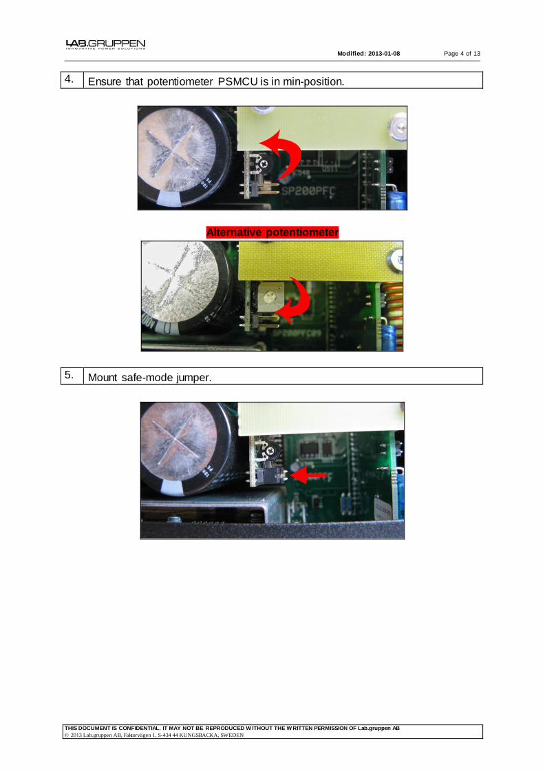
4. Ensure that potentiometer PSMCU is in min-position.
Alternative potentiometer
5. Mount safe-mode jumper.

Modified: 2013-01-08 Page 5 of 13
THIS DOCUMENT IS CONFIDENTIAL. IT MAY NOT BE REPRODUCED W ITHOUT THE W RITTEN PERMISSION OF Lab.gruppen AB
2013 Lab.gruppen AB, Faktorvägen 1, S-434 44 KUNGSBACKA, SWEDEN
6. Ensure that Trimmer Resistor RAIL is in min-position (clockwise from solder
side).
7. Attach multimeter for RAIL and use SG for reference (Pic 1).
Attach multimeter to PFC-voltage and use PPG (Pic 2).
Attach 1:100probe and earth clip for oscilloscope in PPG
Note! Use an isolation transformer for the oscilloscope (Pic3).
Pic 1
Pic 2

Modified: 2013-01-08 Page 6 of 13
THIS DOCUMENT IS CONFIDENTIAL. IT MAY NOT BE REPRODUCED W ITHOUT THE W RITTEN PERMISSION OF Lab.gruppen AB
2013 Lab.gruppen AB, Faktorvägen 1, S-434 44 KUNGSBACKA, SWEDEN
Pic 3
OVERVIEW
8. Plug in power cord, signal cables and network cable. Network cable in
secondary port.
9. Ramp up variable voltage transformer to 110VAC. Start the amplifier on the power button.
Multimeter RAIL ~ 1-5VDC
Multimeter PFC ~22-26VDC

Modified: 2013-01-08 Page 7 of 13
THIS DOCUMENT IS CONFIDENTIAL. IT MAY NOT BE REPRODUCED W ITHOUT THE W RITTEN PERMISSION OF Lab.gruppen AB
2013 Lab.gruppen AB, Faktorvägen 1, S-434 44 KUNGSBACKA, SWEDEN
10. Measure 6 switch nodes with 1:100-probe grounded in PPG.
Important that the wave is symmetrical.

Modified: 2013-01-08 Page 8 of 13
THIS DOCUMENT IS CONFIDENTIAL. IT MAY NOT BE REPRODUCED W ITHOUT THE W RITTEN PERMISSION OF Lab.gruppen AB
2013 Lab.gruppen AB, Faktorvägen 1, S-434 44 KUNGSBACKA, SWEDEN
11. New oscilloscope settings.
12. Slowly ramp up PFC voltage with potentiometer on PSMCU to max (~220VDC)
Alternative potentiometer
Modified: 2013-01-08 Page 9 of 13
THIS DOCUMENT IS CONFIDENTIAL. IT MAY NOT BE REPRODUCED W ITHOUT THE W RITTEN PERMISSION OF Lab.gruppen AB
2013 Lab.gruppen AB, Faktorvägen 1, S-434 44 KUNGSBACKA, SWEDEN
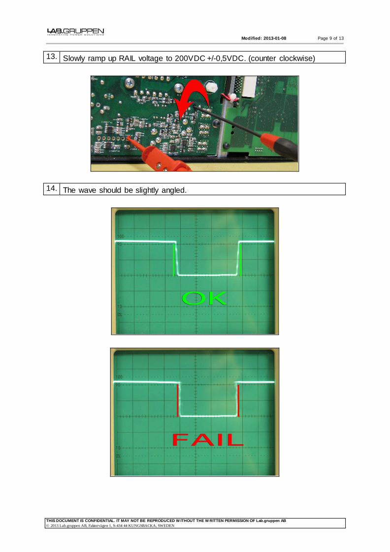
13. Slowly ramp up RAIL voltage to 200VDC +/-0,5VDC. (counter clockwise)
14. The wave should be slightly angled.

Modified: 2013-01-08 Page 10 of 13
THIS DOCUMENT IS CONFIDENTIAL. IT MAY NOT BE REPRODUCED W ITHOUT THE W RITTEN PERMISSION OF Lab.gruppen AB
2013 Lab.gruppen AB, Faktorvägen 1, S-434 44 KUNGSBACKA, SWEDEN
15. If the performed tests have worked according to instruction, turn off the amplifier
with the variable voltage transformer 0VAC.
Remove the safe-mode jumper.
16. Ramp up variable voltage transformer to anywhere between 110 and 230 VAC.
17. RAIL-voltage 200VDC +/-0,5VDC. PFC-voltage ~380VDC
18. Measure 6 switchnodes with 1:100-probe grounded to primary power ground
(PPG) according to earlier picture. In this measurement the output modules are
active and the power supply is running with load. The wave in picA is now
slightly angled, if the wave is straight something is wrong and the power supply will go hot. The break in the wave on picB can occur on slightly different levels.
PicA
PicB
19. Check output signal from one channel at a time by activating mute on the
remaining channels.
Modified: 2013-01-08 Page 11 of 13
THIS DOCUMENT IS CONFIDENTIAL. IT MAY NOT BE REPRODUCED W ITHOUT THE W RITTEN PERMISSION OF Lab.gruppen AB
2013 Lab.gruppen AB, Faktorvägen 1, S-434 44 KUNGSBACKA, SWEDEN
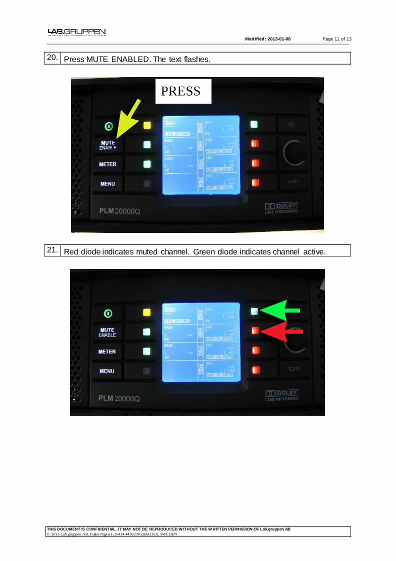
20. Press MUTE ENABLED. The text flashes.
21. Red diode indicates muted channel. Green diode indicates channel active.
PRESS
Modified: 2013-01-08 Page 12 of 13
THIS DOCUMENT IS CONFIDENTIAL. IT MAY NOT BE REPRODUCED W ITHOUT THE W RITTEN PERMISSION OF Lab.gruppen AB
2013 Lab.gruppen AB, Faktorvägen 1, S-434 44 KUNGSBACKA, SWEDEN
22. When testing a channel;
Check so that you get two bars on the user interface also check so that the channel goes into voltage clip.
Check offset with no input (+/- 50mV).
Increase input signal and check output signal at clip 8Ω
Wave measured at 1.3kHz.
Wave measured at 13kHz.
23. When all channels have been tested activate all outputs and inputs.
Power down with power-button.
24. Turn down the variable voltage transformer to 0VAC!
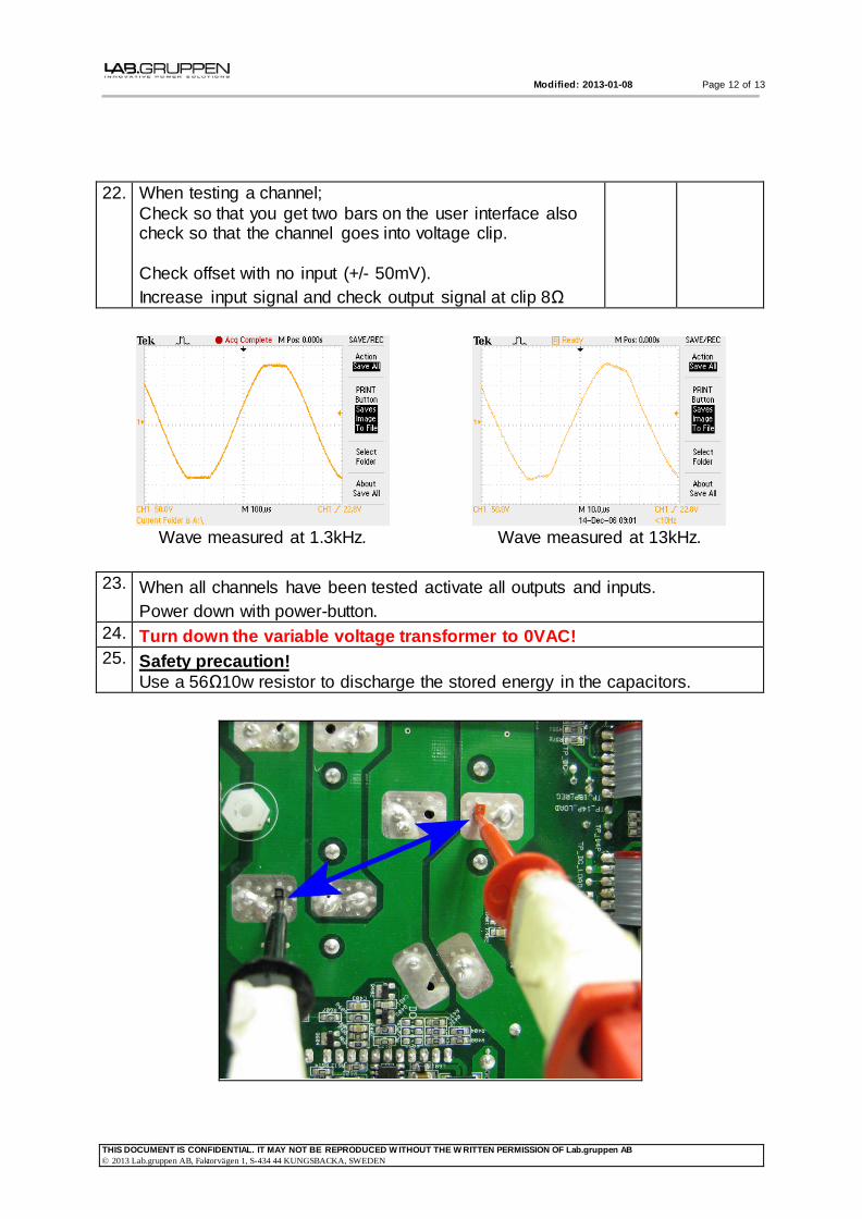
25. Safety precaution!
Use a 56Ω10w resistor to discharge the stored energy in the capacitors.

Modified: 2013-01-08 Page 13 of 13
THIS DOCUMENT IS CONFIDENTIAL. IT MAY NOT BE REPRODUCED W ITHOUT THE W RITTEN PERMISSION OF Lab.gruppen AB
2013 Lab.gruppen AB, Faktorvägen 1, S-434 44 KUNGSBACKA, SWEDEN
26. Check dust filters, change when needed.