checking and repairing a hallicrafters sx-28 gerry o’hara
TRANSCRIPT
Checking and Repairing a Hallicrafters SX-28 – Gerry O’Hara
Overview of the SX-28/28A Receiver
The SX-28 was introduced in August, 1940 and stayed in
production through 1944, with production then swapping to the
SX-28A from late-1944/February 1945 through to July 1946,
after an estimated total of 27,150 SX-28/SX28A’s were
manufactured. The receiver was widely used by the military in
WWII and in the post-war period quite rightly became a very
sought-after and popular receiver within the amateur
community.
The receiver is very solidly
constructed on a stout steel
chassis, weighing-in at 78lbs.
The thick steel front panel is
separate to the main chassis,
with some controls being
mounted directly to this. The
RF circuits are contained in a
series of screened
compartments beneath the chassis, reducing heat build-up here,
however, a temperature-compensating capacitor is included, this
being a negative-temperature coefficient ceramic trimmer located in
the tuning gang compartment above the chassis where the four RF
tubes are located. The gearbox in the SX-28 uses gears to drive both
the main and bandspread gangs, however, the SX-28A uses a dial cord
to drive the bandspread gang. Cords are also used to operate band
indicators on each of the two tuning dials on both models when the bandswitch is operated. Some
other differences between the SX-28 and SX-28A include:
- Construction of the RF circuits: in the SX-28A, ‘Hi-Q Micro Set’ coils with phenolic formers were
mounted on phenolic plates, whereas in the SX-28, the coil units were mounted onto the sub-chassis;
- The coil box cover is screwed in place in the SX-28 and is held on with retaining clips in the SX-28A, the
cover in this model also having a louvered top;
- The SX-28 has open ‘spoke’-style tuning knobs and the SX-28A was fitted with closed-in ‘webbed’- style
tuning knobs.
The Hallicrafters SX-28 and SX-28A receivers are 15-tube single-conversion superheterodyne designs
(nominal 455kHz IF), covering 550kHz through 42MHz in six bands:
550kHz – 1.6MHz
1.6MHz – 3.0MHz
Hallicrafters SX-28 Gerry O’Hara
2
3.0MHz – 5.8MHz
5.8MHz – 11MHz
11MHz – 21 MHz
21MHz – 42MHz
In addition, an electronic bandspread facility is provided in a separate scale for the following frequency
ranges, covering the 80m, 40m, 20m and 10m amateur bands:
3.5MHz – 4.0MHz
7.0MHz – 7.3MHz
14MHz – 14.45MHz
28MHz – 30MHz
The set is designed to receive AM and CW signals, but with care, SSB signals can be received quite well.
Controls include main and bandspread tuning, a six-position selectivity control (three positions with the
single crystal filter in-circuit), crystal phasing, ANL, BFO, AGC on/off, antenna tune, RF gain, AF gain,
tone, a ‘bass boost’ switch and a standby switch.
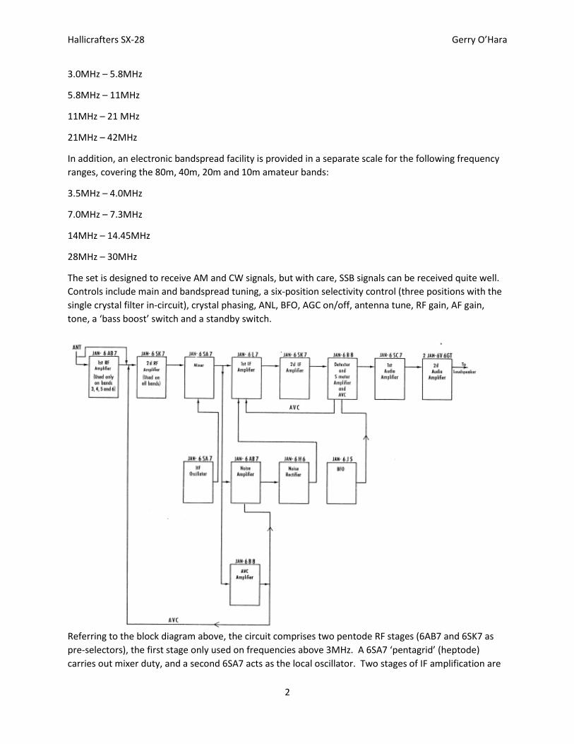
Referring to the block diagram above, the circuit comprises two pentode RF stages (6AB7 and 6SK7 as
pre-selectors), the first stage only used on frequencies above 3MHz. A 6SA7 ‘pentagrid’ (heptode)
carries out mixer duty, and a second 6SA7 acts as the local oscillator. Two stages of IF amplification are
Hallicrafters SX-28 Gerry O’Hara
3
provided, a 6L7 heptode followed by a 6SK7, feeding a
6B8 dual-diode pentode as detector/AGC/S-meter
amplifier. Audio from the detector is fed to a 6SC7 dual
triode doing duty as a pre-amplifier and phase-splitter,
to two 6V6 output tubes in push-pull, giving 8W of
audio. A second 6B8 is used as an AGC
amplifier/detector for the RF and mixer stages, a second
6AB7 as the ANL noise amplifier and a 6H6 dual diode as
the ANL rectifiers (see below). A 6J5 triode is used in the BFO circuit, which is loosely-coupled to the
detector circuit with a ‘gimmick’ capacitor. The power supply is conventional, using a 5Z3 rectifier.
The circuit includes some interesting innovations: there are two AGC circuits – one amplified, feeding
the RF and mixer stages, and the other conventional, controlling the first IF stage. There are also two
ANL circuits: the first provides for shunting of the detector diode load with a capacitor to momentarily
bypass audio signals on noise peaks, the second amplifies the noise signal at the IF frequency and places
an instantaneous negative potential on the 3rd grid of the first IF amplifier (a 6L7 heptode) at a level
selected by the operator thus canceling out noise pulses – this is a version of the Lamb noise silencer
(‘blanker’). The use of permeability-tuned RF transformers using iron-dust slugs was a fairly new
innovation at the time, as was the variable-bandwidth IF and single crystal gate circuitry. Even the S-
meter circuit is a little novel having its own amplifier stage, and the audio output impressively has a pair
of 6V6 tubes in push-pull for great sounding audio, complete with a switchable bass boost circuit.
Background
This SX-28, S/N H164758, originally came from Hans Alderliesten, who has since passed away. Hans was
a former technician at the local Naval Base, and a member of the Victoria Radio Group, of which Lorne
and I are also members. He had sold it to Lorne saying he wanted to make sure it went to a good home,
along with a RACAL RA-17. Hans thought that a resistor had gone bad in the SX-28 but couldn’t
remember. He believed he had replaced the caps at some point but wasn’t sure. Lorne knew it had
been working but did not know how long ago that was. Knowing how meticulous Hans was, Lorne was
sure he had done a good job. Lorne had already undertaken the basic clean-up and cosmetic work on
the cabinet and chassis. Lorne had not tested the chassis and, as he intended to use it fairly frequently,
wanted me to check it over, replace components where needed, and then align it as best I could.
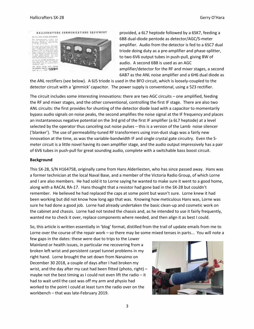
So, this article is written essentially in ‘blog’ format, distilled from the trail of update emails from me to
Lorne over the course of the repair work – so there may be some mixed tenses in parts... You will note a
few gaps in the dates: these were due to trips to the Lower
Mainland or health issues, in particular me recovering from a
broken left wrist and persistent carpel tunnel problems in my
right hand. Lorne brought the set down from Nanaimo on
December 30 2018, a couple of days after I had broken my
wrist, and the day after my cast had been fitted (photo, right) –
maybe not the best timing as I could not even lift the radio – it
had to wait until the cast was off my arm and physio had
worked to the point I could at least turn the radio over on the
workbench – that was late-February 2019.
Hallicrafters SX-28 Gerry O’Hara
4
Preliminary Inspection, Observations and Checks
(Feb 28 2019): I always like to give a chassis a close visual inspection, plus a few basic electrical checks
before I undertake any further work (see my article on radio repairs in the Winter 2019 issue of
‘Canadian Vintage Radios’). This is always time well-spent: you become familiar with the chassis layout
v schematic, identify any obvious issues, eg. burnt-out resistors, poor insulation, suspect dry joints, or
missing dial cord, assess the presence and quality of any previous repairs, check the continuity of
transformers, etc. On this SX-28, the following was noted during this inspection:
- The majority of the original paper caps had been replaced with high quality metal-encapsulated caps
(mainly ‘JAN’ and Gen. Inst.). I tested a random number of these and found their values to be accurate
and to have zero measurable leakage when tested to within 100v of their rated working voltage. Given
the exceptional low leakage, I assessed these caps as likely being plastic film types and tended towards
leaving the majority of these in circuit. The exceptions would be those between the line supply and the
chassis, which should be replaced with Y2-type safety caps;
- Some paper caps had been replaced with plastic-encapsulated caps. These may or may not be paper
or plastic film types. I recommended
replacing all of these with new plastic
film types;
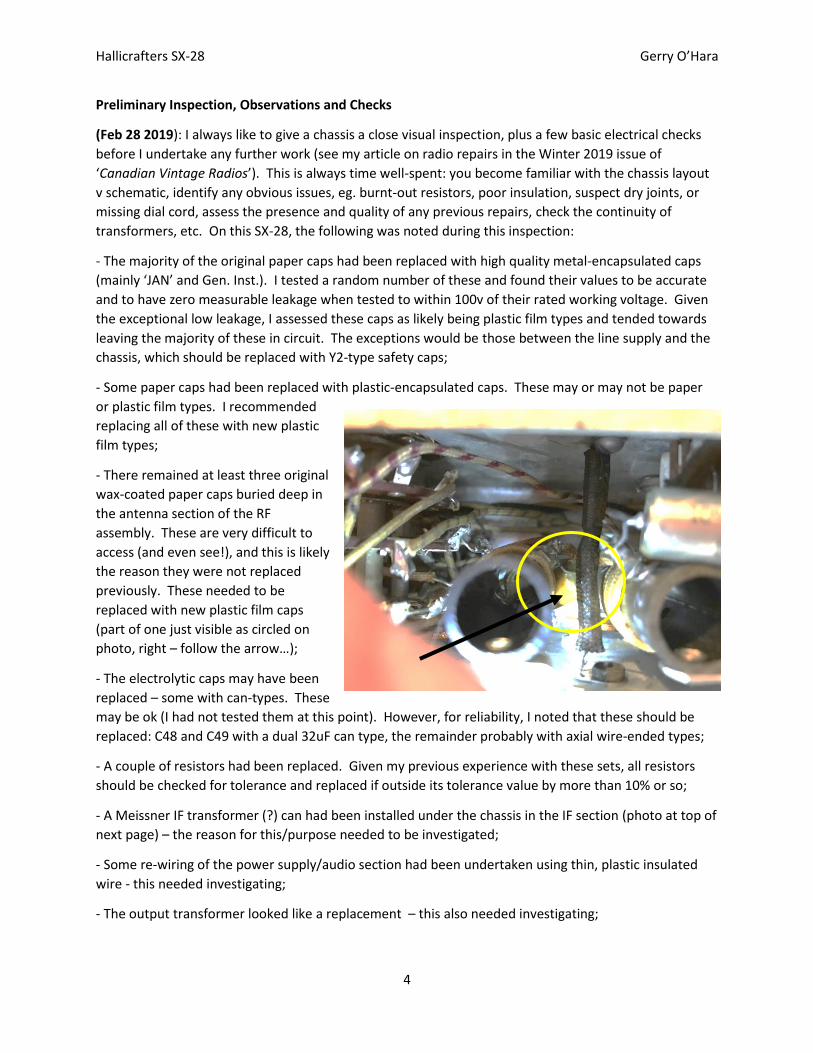
- There remained at least three original
wax-coated paper caps buried deep in
the antenna section of the RF
assembly. These are very difficult to
access (and even see!), and this is likely
the reason they were not replaced
previously. These needed to be
replaced with new plastic film caps
(part of one just visible as circled on
photo, right – follow the arrow…);
- The electrolytic caps may have been
replaced – some with can-types. These
may be ok (I had not tested them at this point). However, for reliability, I noted that these should be
replaced: C48 and C49 with a dual 32uF can type, the remainder probably with axial wire-ended types;
- A couple of resistors had been replaced. Given my previous experience with these sets, all resistors
should be checked for tolerance and replaced if outside its tolerance value by more than 10% or so;
- A Meissner IF transformer (?) can had been installed under the chassis in the IF section (photo at top of
next page) – the reason for this/purpose needed to be investigated;
- Some re-wiring of the power supply/audio section had been undertaken using thin, plastic insulated
wire - this needed investigating;
- The output transformer looked like a replacement – this also needed investigating;
Hallicrafters SX-28 Gerry O’Hara
5
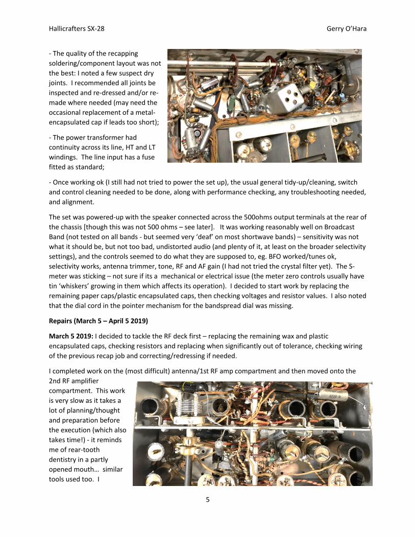
- The quality of the recapping
soldering/component layout was not
the best: I noted a few suspect dry
joints. I recommended all joints be
inspected and re-dressed and/or re-
made where needed (may need the
occasional replacement of a metal-
encapsulated cap if leads too short);
- The power transformer had
continuity across its line, HT and LT
windings. The line input has a fuse
fitted as standard;
- Once working ok (I still had not tried to power the set up), the usual general tidy-up/cleaning, switch
and control cleaning needed to be done, along with performance checking, any troubleshooting needed,
and alignment.
The set was powered-up with the speaker connected across the 500ohms output terminals at the rear of
the chassis [though this was not 500 ohms – see later]. It was working reasonably well on Broadcast
Band (not tested on all bands - but seemed very ‘deaf’ on most shortwave bands) – sensitivity was not
what it should be, but not too bad, undistorted audio (and plenty of it, at least on the broader selectivity
settings), and the controls seemed to do what they are supposed to, eg. BFO worked/tunes ok,
selectivity works, antenna trimmer, tone, RF and AF gain (I had not tried the crystal filter yet). The S-
meter was sticking – not sure if its a mechanical or electrical issue (the meter zero controls usually have
tin ‘whiskers’ growing in them which affects its operation). I decided to start work by replacing the
remaining paper caps/plastic encapsulated caps, then checking voltages and resistor values. I also noted
that the dial cord in the pointer mechanism for the bandspread dial was missing.
Repairs (March 5 – April 5 2019)
March 5 2019: I decided to tackle the RF deck first – replacing the remaining wax and plastic
encapsulated caps, checking resistors and replacing when significantly out of tolerance, checking wiring
of the previous recap job and correcting/redressing if needed.
I completed work on the (most difficult) antenna/1st RF amp compartment and then moved onto the
2nd RF amplifier
compartment. This work
is very slow as it takes a
lot of planning/thought
and preparation before
the execution (which also
takes time!) - it reminds
me of rear-tooth
dentistry in a partly
opened mouth… similar
tools used too. I
Hallicrafters SX-28 Gerry O’Hara
6
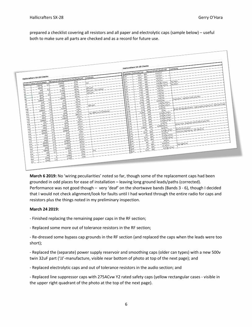
prepared a checklist covering all resistors and all paper and electrolytic caps (sample below) – useful
both to make sure all parts are checked and as a record for future use.
March 6 2019: No ‘wiring peculiarities’ noted so far, though some of the replacement caps had been
grounded in odd places for ease of installation – leaving long ground leads/paths (corrected).
Performance was not good though – very ‘deaf’ on the shortwave bands (Bands 3 - 6), though I decided
that I would not check alignment/look for faults until I had worked through the entire radio for caps and
resistors plus the things noted in my preliminary inspection.
March 24 2019:
- Finished replacing the remaining paper caps in the RF section;
- Replaced some more out of tolerance resistors in the RF section;
- Re-dressed some bypass cap grounds in the RF section (and replaced the caps when the leads were too
short);
- Replaced the (separate) power supply reservoir and smoothing caps (older can types) with a new 500v
twin 32uF part (‘JJ’-manufacture, visible near bottom of photo at top of the next page); and
- Replaced electrolytic caps and out of tolerance resistors in the audio section; and
- Replaced line suppressor caps with 275ACvw Y2 rated safety caps (yellow rectangular cases - visible in
the upper right quadrant of the photo at the top of the next page).
Hallicrafters SX-28 Gerry O’Hara
7
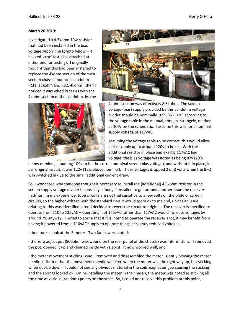
March 26 2019:
Investigated a 4.5kohm 10w resistor
that had been installed in the bias
voltage supply line (photo below – it
has red ‘croc’ test clips attached at
either end for testing). I originally
thought that this had been installed to
replace the 4kohm section of the twin
section chassis-mounted candohm
(R31, 11kohm and R32, 4kohm), then I
noticed it was wired in series with the
4kohm section of the candohm, ie. the
4kohm section was effectively 8.5kohm. The screen
voltage (bias) supply provided by this candohm voltage
divider should be nominally 109v (+/- 10%) according to
the voltage table in the manual, though, strangely, marked
as 100v on the schematic. I assume this was for a nominal
supply voltage of 117vAC.
Assuming the voltage table to be correct, this would allow
a bias supply up to around 120v to be ok. With the
additional resistor in place and exactly 117vAC line
voltage, the bias voltage was noted as being 87v (20%
below nominal, assuming 109v to be the correct nominal screen bias voltage), and without it in place, ie.
per original circuit, it was 122v (12% above nominal). These voltages dropped 2 or 3 volts when the BFO
was switched in due to the small additional current draw.
So, I wondered why someone thought it necessary to install the (additional) 4.5kohm resistor in the
screen supply voltage divider? – possibly a ‘bodge’ installed to get around another issue the receiver
had/has. In my experience, tube circuits are not that sensitive to a few volts on the plate or screen
circuits, so the higher voltage with the standard circuit would seem ok to me and, unless an issue
relating to this was identified later, I decided to revert the circuit to original. The receiver is specified to
operate from 110 to 125vAC – operating it at 125vAC rather than 117vAC would increase voltages by
around 7% anyway. I noted to Lorne that if it is intend to operate the receiver a lot, it may benefit from
having it powered from a 110vAC supply to operate things at slightly reduced voltages.
I then took a look at the S-meter. Two faults were noted:
- the zero adjust pot (500ohm wirewound on the rear panel of the chassis) was intermittent. I removed
the pot, opened it up and cleaned inside with Deoxit. It now worked well; and
- the meter movement sticking issue: I removed and disassembled the meter. Gently blowing the meter
needle indicated that the movement/needle was free when the meter was the right way up, but sticking
when upside down. I could not see any obvious material in the coil/magnet air gap causing the sticking
and the springs looked ok. On re-installing the meter in the chassis, the meter was noted as sticking all
the time at various (random) points on the scale. So, I could not resolve this problem at this point,
Hallicrafters SX-28 Gerry O’Hara
8
noting that it was possibly a bad/misaligned bearing issue. I noted to Lorne that more extensive fiddling
with the movement may fix it, but in my experience its maybe better to try to find another meter
movement that could be substituted. An external meter connected to the circuit worked ok, so the
problem was definitely a mechanical one in the meter mechanism.
March 27 2019: I operated the receiver for a couple of hours after I removed the ‘extra’ resistor in the
bias line. It was receiving a local Broadcast station without any antenna connected. During various
voltage checks at critical circuit nodes and tube bases, I noted that the ‘cold’ end of the 1kohm 1st RF
stage plate feed resistor (R5) was at the same voltage as the HT supply line, ie. the resistor was not
dropping any voltage as the tube was not drawing current. I felt the 1st RF tube (6AB7) and it was cool
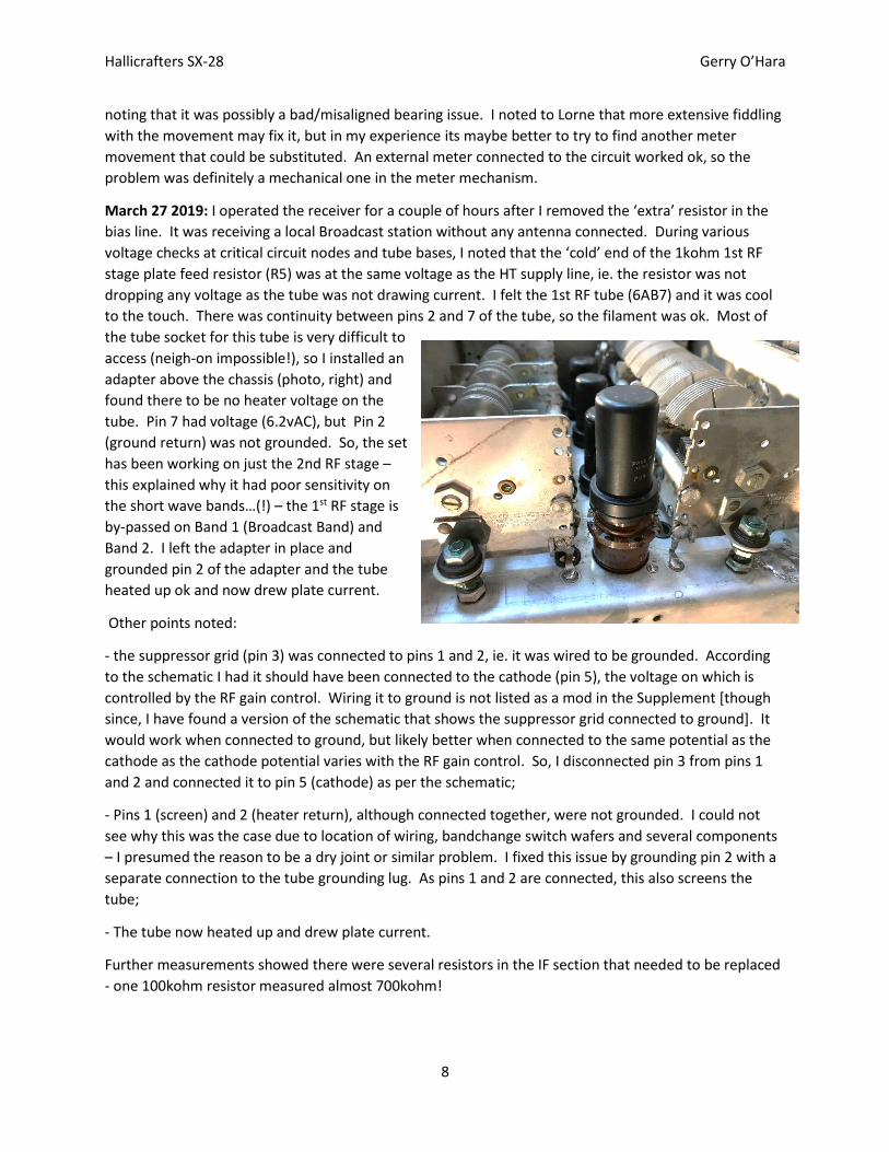
to the touch. There was continuity between pins 2 and 7 of the tube, so the filament was ok. Most of
the tube socket for this tube is very difficult to
access (neigh-on impossible!), so I installed an
adapter above the chassis (photo, right) and
found there to be no heater voltage on the
tube. Pin 7 had voltage (6.2vAC), but Pin 2
(ground return) was not grounded. So, the set
has been working on just the 2nd RF stage –
this explained why it had poor sensitivity on
the short wave bands…(!) – the 1st RF stage is
by-passed on Band 1 (Broadcast Band) and
Band 2. I left the adapter in place and
grounded pin 2 of the adapter and the tube
heated up ok and now drew plate current.
Other points noted:
- the suppressor grid (pin 3) was connected to pins 1 and 2, ie. it was wired to be grounded. According
to the schematic I had it should have been connected to the cathode (pin 5), the voltage on which is
controlled by the RF gain control. Wiring it to ground is not listed as a mod in the Supplement [though
since, I have found a version of the schematic that shows the suppressor grid connected to ground]. It
would work when connected to ground, but likely better when connected to the same potential as the
cathode as the cathode potential varies with the RF gain control. So, I disconnected pin 3 from pins 1
and 2 and connected it to pin 5 (cathode) as per the schematic;
- Pins 1 (screen) and 2 (heater return), although connected together, were not grounded. I could not
see why this was the case due to location of wiring, bandchange switch wafers and several components
– I presumed the reason to be a dry joint or similar problem. I fixed this issue by grounding pin 2 with a
separate connection to the tube grounding lug. As pins 1 and 2 are connected, this also screens the
tube;
- The tube now heated up and drew plate current.
Further measurements showed there were several resistors in the IF section that needed to be replaced
- one 100kohm resistor measured almost 700kohm!
Hallicrafters SX-28 Gerry O’Hara
9
March 28 2019: All out of tolerance resistors were changed out except one. Amazingly, one resistor in
the Noise Limiter circuit was missing completely(!) – likely from new. It was the anode load resistor for
V9, so the Noise Limiter would not have worked. The resistor not yet changed was inside the T1
transformer housing (R62, which should be 500kohms, but measured 768kohms). It’s the grid leak for
the AVC amplifier, V8, so its value is not critical. Rather than pull T1 apart (unless I need to for another
reason – see below) I decided to leave well-alone. I also found a couple more wiring errors (corrected)
and incorrect replacement capacitor values (also corrected).
March 29 2019: All paper and electrolytic caps now checked and replaced where needed. I also re-
dressed some component leads and checked they had all been installed at the correct points in the
circuit. All remnant caps were replaced by others in the
past with high quality JAN or Gen Inst. types (except
two yellow square body types that were plastic film -
replaced), and all tested good.
On inspecting the wiring, I found that the Meissner IF
transformer under the chassis was actually being used
as a substitute for Choke 3 and associated trimmer C55,
which together act as a 455kHz wave trap in the
automatic noise limiter (ANL) circuit. Perhaps the
original choke burned out at some point – though I
could not see why a component failure would do that,
so maybe it developed a ‘green wire’ corrosion
problem, or someone shorted a high voltage to it when
checking something else – who knows…. I decided that
if it was working ok when I checked the ANL, to leave it
in place.
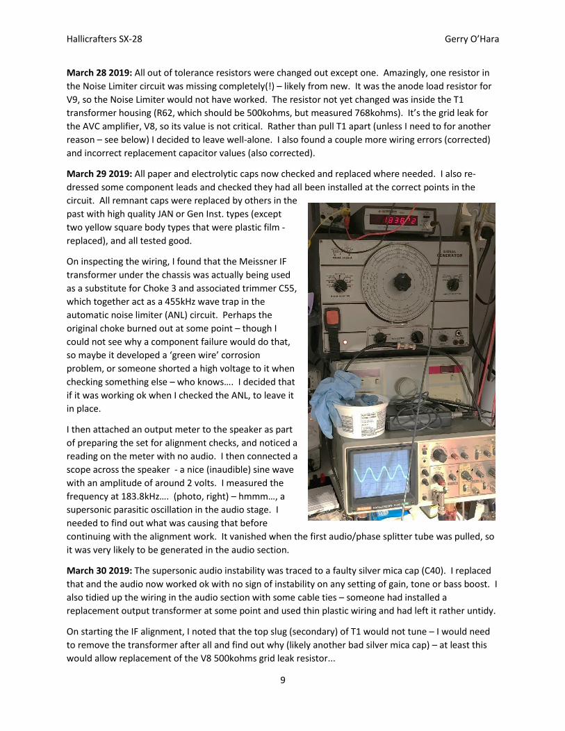
I then attached an output meter to the speaker as part
of preparing the set for alignment checks, and noticed a
reading on the meter with no audio. I then connected a
scope across the speaker - a nice (inaudible) sine wave
with an amplitude of around 2 volts. I measured the
frequency at 183.8kHz…. (photo, right) – hmmm…, a
supersonic parasitic oscillation in the audio stage. I
needed to find out what was causing that before
continuing with the alignment work. It vanished when the first audio/phase splitter tube was pulled, so
it was very likely to be generated in the audio section.
March 30 2019: The supersonic audio instability was traced to a faulty silver mica cap (C40). I replaced
that and the audio now worked ok with no sign of instability on any setting of gain, tone or bass boost. I
also tidied up the wiring in the audio section with some cable ties – someone had installed a
replacement output transformer at some point and used thin plastic wiring and had left it rather untidy.
On starting the IF alignment, I noted that the top slug (secondary) of T1 would not tune – I would need
to remove the transformer after all and find out why (likely another bad silver mica cap) – at least this
would allow replacement of the V8 500kohms grid leak resistor...
Hallicrafters SX-28 Gerry O’Hara
10
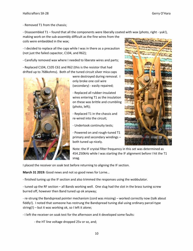
- Removed T1 from the chassis;
- Disassembled T1 – found that all the components were liberally coated with wax (photo, right - yuk!),
making work on the sub-assembly difficult as the fine wires from the
coils were embedded in the wax;
- I decided to replace all the caps while I was in there as a precaution
(not just the failed capacitor, C104, and R62);
- Carefully removed wax where I needed to liberate wires and parts;
- Replaced C104, C105 C61 and R62 (this is the resistor that had
drifted up to 768kohms). Both of the tuned circuit silver mica caps
were destroyed during removal. I
only broke one coil wire
(secondary) - easily repaired;
- Replaced all rubber-insulated
wires entering T1 as the insulation
on these was brittle and crumbling
(photo, left);
- Replaced T1 in the chassis and
re-wired into the circuit;
- Undertook continuity tests;
- Powered on and rough-tuned T1
primary and secondary windings –
both tuned up nicely.
Note: the IF crystal filter frequency in this set was determined as
454.250kHz while I was starting the IF alignment before I hit the T1
snag.
I placed the receiver on soak test before returning to aligning the IF section.
March 31 2019: Good news and not so good news for Lorne…
- finished tuning up the IF section and also trimmed the responses using the wobbulator.
- tuned up the RF section – all Bands working well. One slug had the slot in the brass tuning screw
burred off, however then Band tuned up ok anyway;
- re-strung the Bandspread pointer mechanism (cord was missing) – worked correctly now (talk about
fiddly!). I noted that someone has restrung the Bandspread tuning dial using ordinary parcel-type
string(!) – but it was working ok, so I left it alone;
- I left the receiver on soak test for the afternoon and it developed some faults:
- the HT line voltage dropped 25v or so, and;
Hallicrafters SX-28 Gerry O’Hara
11
- the IF section developed a fault that caused a significant drop in signal strength.
Nothing was obviously causing these issues, though I noticed a slight smell - but could not trace it.
April 1 2019: During troubleshooting, I found two issues:
- There was a resistance of 516kohms measured between the IF AGC line and ground, even with all
components disconnected. I could not find what was causing this [at this time] ,and it would not cause
the symptoms I described yesterday; and
- The replacement 250pf 500vw silver mica cap that connects the plate of V3 to the grid (top cap) of V8
(C61) had failed and was now acting as a 318ohm resistor – aaarghhh!! This was a brand new part
installed as a precaution when I had T1 opened up. I have never had a new silver mica fail like that, and
I had even tested it before I fitted it. It was a new 500v part that had around 280v across it in operation.
This failure would have the following implications:
- HT would be applied to the grid of V8;
- V8 would therefore be conducting heavily (which I had noted was running hot after the problem
occurred);
- V8 would be drawing excessive anode current, likely the reason for the reduced HT line voltage;
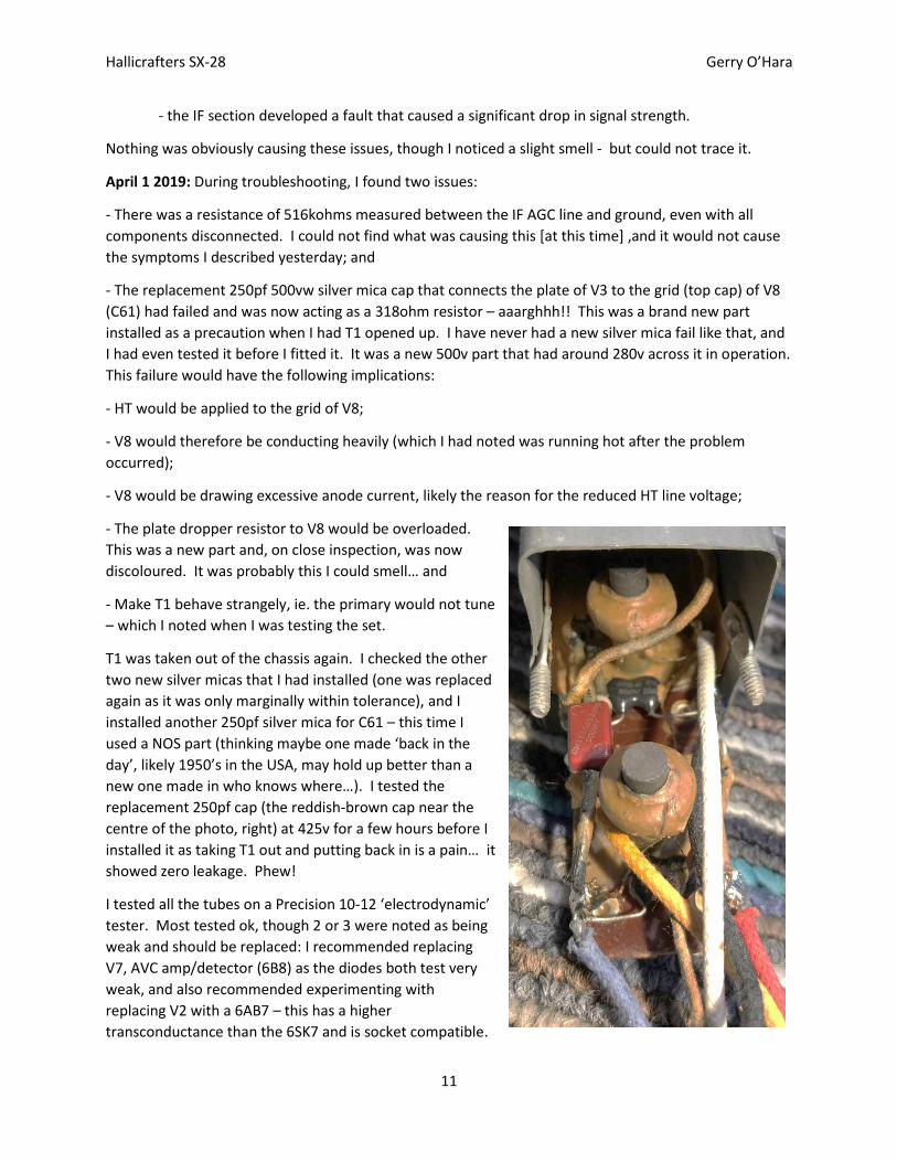
- The plate dropper resistor to V8 would be overloaded.
This was a new part and, on close inspection, was now
discoloured. It was probably this I could smell… and
- Make T1 behave strangely, ie. the primary would not tune
– which I noted when I was testing the set.
T1 was taken out of the chassis again. I checked the other
two new silver micas that I had installed (one was replaced
again as it was only marginally within tolerance), and I
installed another 250pf silver mica for C61 – this time I
used a NOS part (thinking maybe one made ‘back in the
day’, likely 1950’s in the USA, may hold up better than a
new one made in who knows where…). I tested the
replacement 250pf cap (the reddish-brown cap near the
centre of the photo, right) at 425v for a few hours before I
installed it as taking T1 out and putting back in is a pain… it
showed zero leakage. Phew!
I tested all the tubes on a Precision 10-12 ‘electrodynamic’
tester. Most tested ok, though 2 or 3 were noted as being
weak and should be replaced: I recommended replacing
V7, AVC amp/detector (6B8) as the diodes both test very
weak, and also recommended experimenting with
replacing V2 with a 6AB7 – this has a higher
transconductance than the 6SK7 and is socket compatible.
Hallicrafters SX-28 Gerry O’Hara
12
April 2 2019:
T1 was re-fitted and the set was working ok, with the HT and screen voltages normal (279v and 110v
respectively). I noted that V8 was still hot to the touch, but maybe that is normal, as V7 (another 6B8)
was also hot.
On re-fitting T1, I noticed that the set had a wiring error, possibly from a repair done years ago: the
‘cold’ end of R62 (V8 grid leak) had been connected to the incorrect tag on a small tagstrip under T1.
Instead of being connected to the ground tag, it was connected to the IF AGC line(!). This is what had
been causing the unexplained 516kohms resistance to ground noted earlier. This was now corrected
(when I re-fitted T1 the first time I just copied where it had been connected to previously). I also
replaced the scorched resistor (R63), even though it was still within tolerance. On powering-up, T1 was
tuning normally again.
After the radio seemed to be running nice and stable for a few
hours, I started to re-align the IF again. All went well until I
started to adjust C31 (the crystal balancing trimmer) – it
adjusted fine last time I had adjusted it. This time it had no
effect (it should peak at the crystal resonant frequency). The
reason is that the centre bush had broken off (a very cheaply
made part – upper trimmer in photo, right – I have had issues
with these in other Hallicrafters repairs). It’s a 4 – 20pf ceramic
trimmer. I had several similar ones in stock (4.5 – 25pf), so
selected a good one - much better quality than the Hallicrafters
one too (lower trimmer in same photo for comparison).
April 4 2019: I fully aligned the RF deck. I noted that Band 6 was not the best above 30MHz or so (but
apparently never was), and age has done nothing to improve things – mind you, there is nothing to
listen to up there anyway.
I completed the checklist and noted that a total of 38 resistors and 28 capacitors had been replaced by
me (some twice!). I did not replace any tubes as my
stock is not accessible since I moved house last
year... one day I will get things organized better!
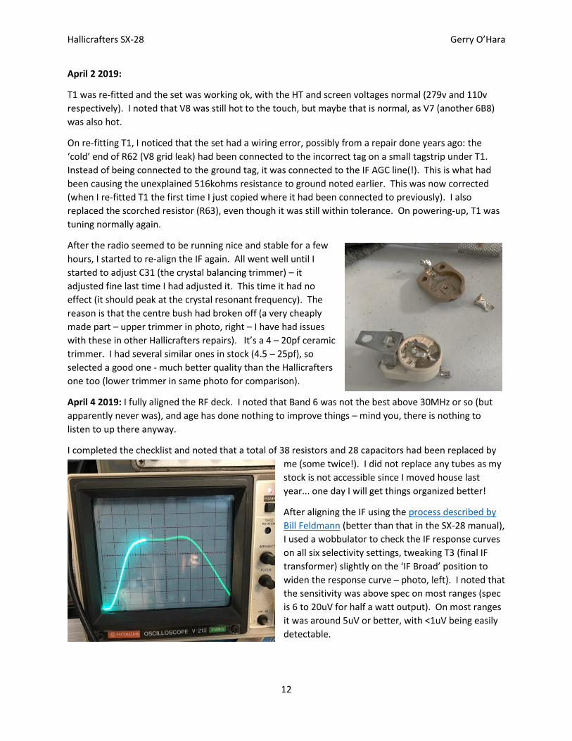
After aligning the IF using the process described by
Bill Feldmann (better than that in the SX-28 manual),
I used a wobbulator to check the IF response curves
on all six selectivity settings, tweaking T3 (final IF
transformer) slightly on the ‘IF Broad’ position to
widen the response curve – photo, left). I noted that
the sensitivity was above spec on most ranges (spec
is 6 to 20uV for half a watt output). On most ranges
it was around 5uV or better, with <1uV being easily
detectable.
Hallicrafters SX-28 Gerry O’Hara
13
After soak testing again for about 9 hours, including some on/off cycles and using the set on various
bands, the following points were noted:
- HT was around 280v and screen supply around 110v, so both nominally at spec;
- The S-Meter worked but still stuck intermittently – a tap usually got it working again;
- There was noticeable mixer noise (a little higher than I would expect), and alignment would not
eliminate this. I suggested to Lorne that he might want to change out the 6SA7s, and also the 6B8 with
weak diodes (V7) to see if there is any improvement;
- Overall, the set is ‘well worn’ and has seen a lot of use (and likely abuse) over the last 77 years or so:
some of the resultant issues are worn threads/slackness in some of the IF and RF tuning slugs,
potentially more problems with the poor quality ceramic trimmers in the future, and a rather sloppy
gearbox with a very free-running mechanism – I suggested trying a little Rocol ‘Kilopoise’ on some of the
gearing to give it a smoother/’tighter’ feel (use very sparingly);
- The workmanship of whoever replaced most of the paper caps was not the best – they left part of the
old components leads in place and soldered the replacement caps to these. I tidied-up and re-dressed
some to look a bit better and also to improve grounding arrangements, but the overall appearance is
still not good. At least they had used top quality
components and these should be very reliable;
- Like any old radio, it could (will) develop faults in
the future, though very few original resistors and
capacitors remain. The original resistors that are left
are within their stated tolerances, but could drift
(likely over decades, but who can tell?), and the only
original caps remaining are silver mica ones, but
these can also develop issues in time (as can brand
new ones, as the fun and games I had with C61
showed!); and
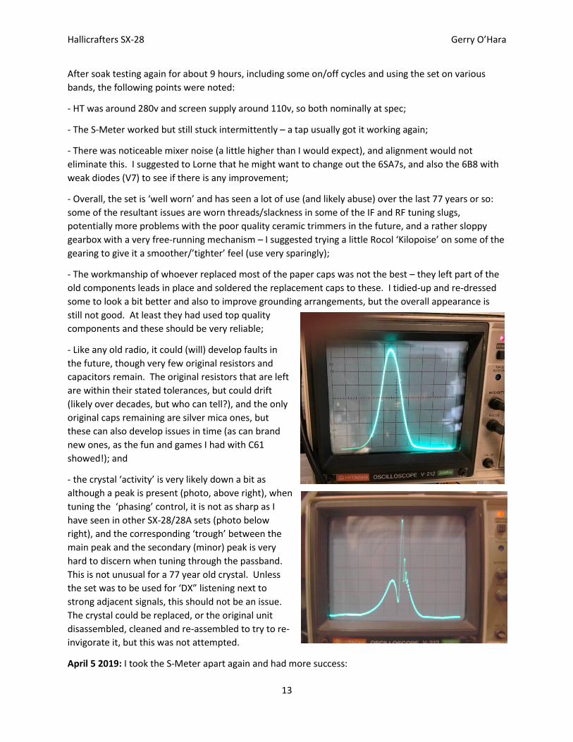
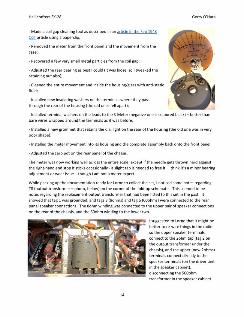
- the crystal ‘activity’ is very likely down a bit as
although a peak is present (photo, above right), when
tuning the ‘phasing’ control, it is not as sharp as I
have seen in other SX-28/28A sets (photo below
right), and the corresponding ‘trough’ between the
main peak and the secondary (minor) peak is very
hard to discern when tuning through the passband.
This is not unusual for a 77 year old crystal. Unless
the set was to be used for ‘DX” listening next to
strong adjacent signals, this should not be an issue.
The crystal could be replaced, or the original unit
disassembled, cleaned and re-assembled to try to re-
invigorate it, but this was not attempted.
April 5 2019: I took the S-Meter apart again and had more success:
Hallicrafters SX-28 Gerry O’Hara
14
- Made a coil gap cleaning tool as described in an article in the Feb 1943
QST article using a paperclip;
- Removed the meter from the front panel and the movement from the
case;
- Recovered a few very small metal particles from the coil gap;
- Adjusted the rear bearing as best I could (it was loose, so I tweaked the
retaining nut also);
- Cleaned the entire movement and inside the housing/glass with anti-static
fluid;
- Installed new insulating washers on the terminals where they pass
through the rear of the housing (the old ones fell apart);
- Installed terminal washers on the leads to the S-Meter (negative one is coloured black) – better than
bare wires wrapped around the terminals as it was before;
- Installed a new grommet that retains the dial light on the rear of the housing (the old one was in very
poor shape);
- Installed the meter movement into its housing and the complete assembly back onto the front panel;
- Adjusted the zero pot on the rear panel of the chassis.
The meter was now working well across the entire scale, except if the needle gets thrown hard against
the right-hand end stop it sticks occasionally - a slight tap is needed to free it. I think it’s a minor bearing
adjustment or wear issue – though I am not a meter expert!
While packing up the documentation ready for Lorne to collect the set, I noticed some notes regarding
T8 (output transformer – photo, below) on the corner of the fold-up schematic. This seemed to be
notes regarding the replacement output transformer that had been fitted to this set in the past. It
showed that tag 1 was grounded, and tags 3 (8ohms) and tag 6 (60ohms) were connected to the rear
panel speaker connections. The 8ohm winding was connected to the upper pair of speaker connections
on the rear of the chassis, and the 60ohm winding to the lower two.
I suggested to Lorne that it might be
better to re-wire things in the radio
so the upper speaker terminals
connect to the 2ohm tap (tag 2 on
the output transformer under the
chassis), and the upper (now 2ohms)
terminals connect directly to the
speaker terminals (on the driver unit
in the speaker cabinet),
disconnecting the 500ohm
transformer in the speaker cabinet
Hallicrafters SX-28 Gerry O’Hara
15
completely. A 2ohm to 3.2ohm mismatch being better than a 60ohms to 500ohms (or maybe even a
5000ohms1) mismatch.
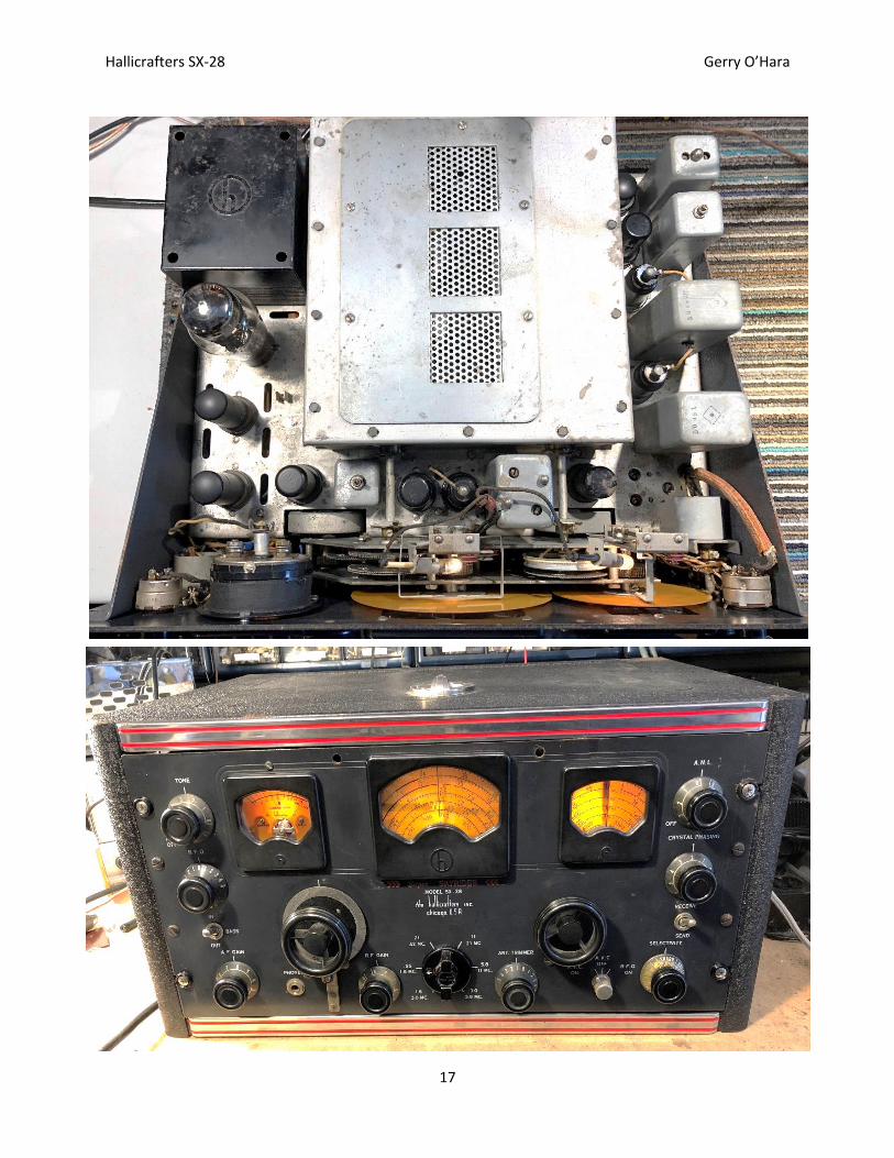
Finally, the chassis was re-installed in its great-looking art-deco metal table top cabinet – complete with
red ‘go-faster’ stripes, ready for Lorne to take away and enjoy.
1 Some information on the PM23 speaker indicates a 500ohm, others a 5000ohm primary on the matching transformer
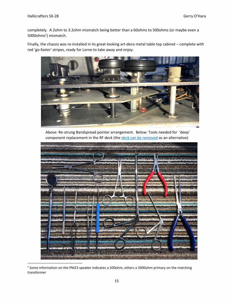
Above: Re-strung Bandspread pointer arrangement. Below: Tools needed for ‘deep’
component replacement in the RF deck (the deck can be removed as an alternative)
Hallicrafters SX-28 Gerry O’Hara
16
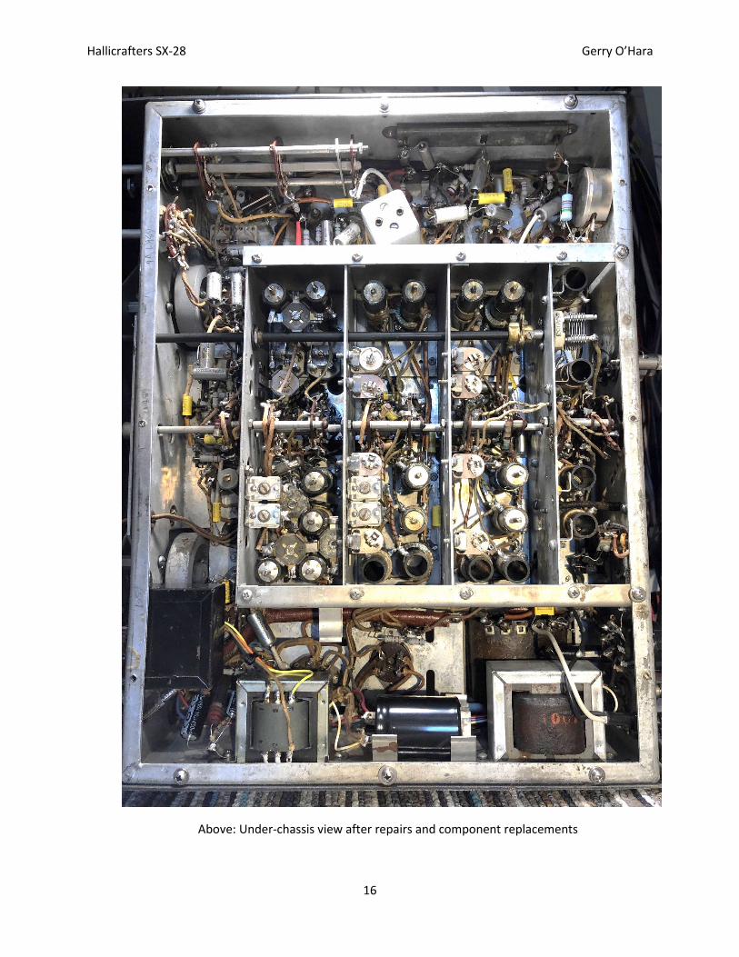
Above: Under-chassis view after repairs and component replacements
Hallicrafters SX-28 Gerry O’Hara
17