check valves - wafer style - pk...
TRANSCRIPT

www.australianpipelinevalve.com.au
CheCk ValVes - Wafer style
Sub brand Super Check Check Valves Wafer Dual & Single Flap WebV.indd 1 30/5/13 4:34:13 PM

QUALITY VALVE MANUFACTURER
QUALITY COMMITMENT
Quality is Our First Priority, and is
achieved by embracing a philosophy
of Total Quality Commitment.

ContentsPage 4-6Page 7-15Page 16-24Page 25Page 26-29Page 30-31Page 32-33Page 34-35Page 36-39
Wafer Check Dual Flap Iron Body SG12 SeriesWafer Check Dual Flap Steel Body SG SeriesWafer Check Dual Flap Steel Body GW Series
Wafer Check Dual Flap TUF-SKINWafer Check Single Flap Long Pattern SLP/SW Series
Wafer Check Super-Lite Model 2024Wafer Check Non Slam Axial Disc Model NSSLSCWafer Check Threaded In-Line Model R-APSC-V
Non Slam Nozzle Check Valve
AUSTRALIAN PIPELINE VALVE®
70-78 Stanbel Road Salisbury Plain South Australia 5109Telephone +61 (0)8 8285 0033 Fax +61 (0)8 8285 0044
email: [email protected]

Wafer Check Dual FlapIron Body
PAGE 4
• Alleviation from Water HammerReaction of torsion spring makes plates rapidlyclose prior to the start of reverse flow of fluiddue to the stop of power, thus prevents damagefrom water, hammering caused by pumps andother reciprocating devices.
PN10 & PN16 RATED
DESIGN FEATURES
BILL OF MATERIALS
IMPORTANT:Ensure the valve is at least eight pipe diametersfrom reciprocating or pulsating devices.
Part Name Materials
1 BODY Iron 126 Class B, Ductile Iron
2 PLATE Bronze, 304SS, 410SS, 316SS, iron etc
3 SPRING 316SS
4 PIN 304SS or 316SS
5 BODY SEAT NBR (BUNA), EPDM, Viton, Metal
7 BEARING PTFE
9 RETAINER S25C or S/S
10 EYE BOLT SS41
• Lower Head LossDesigned with optimum venturi to reduce head losswhen compared with similar Dual Plate Type CheckValves.
• Installation Directions In addition to the compact size, SUPER-CHECKvalves can be installed either horizontally or vertically.
• Long Leg Torsion SpringAction which allows the plates to open and closewithout seat scrubbing.
• Super-Check provide a complete range of sizesfrom ND40 through ND 1800, designed and rated inaccordance with ANSI 125 LB
SG12 Series
Rating (cold) :- 16 Bar (232 PSI). Over 200NB10 bar but 16 & 20 bar also available. Also available inTufskin style (rubber lined) in10, 16 and 20 bar.Max temp :- -18ºC* to 100ºC Buna - N, -18ºC* to 110ºCEPDM, -18ºC* to 121ºC metal seat (As Body).Flanging :- To suit ASA 150, PN10, PN16, AST-D/E(SGBD12, SGBE121). • Soft seated valves zero leakage, metal seated3CC/min/inch of valve size per API598
* Iron body limitation -18°C

PAGE 5
• Non-SlamSUPER-CHECK is a non-slam check valve
because it operates on flow cessation, not
flow reversal. The normal position of the
plates is closed, held against the seat by the
unique spring design. As flow begins, the
heels of the two plates are lifted off the seat
face on the central rib.
This cracking pressure is less than 2 psi
across most of the range (larger sizes can be
more). As flow increases, the plates then
pivot against the spring pressure. Since the
heels have already lifted off the rib seat
there is no scrub or wear, either on the rib,
body or plate seating surfaces. A pressure
of only 4 psi is required to keep the plates
fully open.
When flow stops and the pressure ceases,
the spring closes the plates. Flow reversal is
then stopped by the closed Supercheck
valve and in fact any back pressure only
serves to make the valve seal more tightly.
DIMENSIONS(To suit ASA125 AND BS Table E Flanging)
* In 300NB to 600NB the OD (A/A1) design is often smaller than shown to facilitate multiple flange patterns but a lifting eye is fitted to allow valve to be centralised
HEAD LOSS CURvES
Opening Degree of Plates Flow Rate Pressure Wave
15˚C Water
(50m
/m)
(65m
/m)
(80m
/m)
(100
m/m
)(1
25m
/m)
(150
m/m
)
(200
m/m
)(2
50m
/m)
(300
m/m
)
2" 21/2" 3" 4" 5" 6" 8" 10" 12"
0.1
0.2
0.30.40.50.60.71.0
2.0
3.0
5.06.07.0
10
20
3040506070100
ft
10 20 30 40 7050 60 100
200
300
400
500
600
700
1000
2000
3000
4000
5000
6000
7000
10000
20000
30000
40000
50000
60000
70000
100000
U.S. Gallons per minute
Hea
d Lo
ss
4.0
FLOW
GR
ND SuitFlanging Facing Dimensions Weight
(Kgs)øA A1 B B1 C D GR50 BST-E FF 98 43 60 26 32 3
125 105 104 54 60 26 32 465 BST-E FF 111 0 46 73 26 37 4
125 124 123 54 73 26 37 580 BST-E FF 130 64 89 28 45 5
125 136 134 73 89 38 45 6100 BST-E FF 164 158 64 114 31 53 6
125 175 174 64 114 31 53 8125 BST-E FF 194 190 70 141 32 67 9
125 197 190 70 141 32 67 10150 BST-E FF 215 76 168 31 79 10
125 222 219 76 168 31 79 16200 BST-E FF 276 270 89 219 38 105 19
125 279 270 95 219 38 105 30250 BST-E FF 336 332 114 274 43 123 31
125 340 332 108 274 43 123 45*300 BST-E FF 382 77 114 324 59 155 56
125 410 403 143 324 69 153 80*350 BST-E FF 446 434 127 356 4 170 71
125 451 434 184 356 94 170 71*375 BST-E FF 471 140 406 89 95 99*400 BST-E FF 497 483 191 406 89 195 99
125 514 500 191 406 89 195 99*450 BST-E FF 560 538 152 457 86 219 118
125 549 538 203 457 86 219 118*500 BST-E FF 617 595 152 508 89 244 180
125 606 595 223 508 89 244 180*600 BST-E FF 795 698 178 610 87 300 258
125 718 698 222 610 87 292 258
LOW WAVE
SG12 Series

PAGE 6 ®
Style Body and Plates*
Rating
Seat
Ends
Modifier for Alternate plates (flaps) and seat overlay
Spring Material3
5
2
41
9
7
1 2 3 4 5 6 7 8 9
Other Trim Material (hinge pin, stop pin)8
Part Number System Dual Flap Check
*Body & plate are same material unless partnumber modified suffix (9) indicates differentplate material.
*Modifier suffix (9) indicates specialoverlay materials. P Seat is ‘as body’ ifno modifier suffix.
SG Standard Design.
GW Retainerless Design
12 ANSI Class 125
15 ANSI Class 150
25 ANSI Class 250
30 ANSI Class 300
40 ANSI Class 400
60 ANSI Class 600
90 ANSI Class 900
150 ANSI Class 1500
250 ANSI Class 2500
21 API 2000
31 API 3000
51 API 5000
101 API 10000
151 API 15000
BD12 BS Table D
BE12 BS Table E
BF BS Table F
BH BS Table H
BJ BS Table J
6 DIN/JIS PN06
10 DIN/JIS PN10
16 DIN/JIS PN16
25 DIN/JIS PN25
40 DIN/JIS PN40
A 4130/4140/A487 4C (API6A)
B Aluminium Bronze
C 316/CF8M Stainless Steel
D 304/CF8 Stainless Steel
E 410/F6A/CA15 Stainless Steel
F Alloy 20
G Low Temp. C.S. LF2/LCB
H Cast Iron
HD Ductile Iron
M Monel
S Carbon Steel A105/WCB
T 317 SS
U WC6 Alloy Steel
V 347 SS
W 316L SS/CF3M
X WC9 Alloy Steel
Y C5 Alloy Steel
AF F6A
CA CD3MN Duplex SS
DZ F51 Duplex/S31803 SS
FN Inconel®
GC LCC Low Temp. Steel
SC WCC Steel
TT Titanium
Z Special
A EPDM
H HNBR
M Buna/NBR
N Neoprene
P Metal*
V Viton B
Z Special
F Raised Face (serrated)
G Graylock® Hub
P Plain Face
R Ring Joint
W Buttweld1 304 SS Plates
2 AL Bronze Plates
3 Ductile Iron Plates
4 316 SS Plates
39 410 SS Plates
40 410 Plates, Stellite overlay Seat
41A 316 Plates, Stellite Seat & Plates
42B 316 Plates, Stellite overlay Seat
61A 410 Plates, Stellite Seat & Plates
72A WCB Plates, Stellite Seat & Plates
72B WCB Plates, Stellite overlay Seat
88 316 Plates, 316 overlay Seat
169 410 Plates, 410 overlay Seat
999 Special
4 316 SS
5 304 SS
6 Aluminium Bronze
8 Inconel 600
9 Inconel X750
1 304 SS
3 F51/ UNS S31803
4 316 SS
5 410 SS
8 AL-Bronze
9 A20
SG 12 H M P 1 - 4 4 - 2
Body Type6
None Wafer Style
(Blank)
1 Lugged & Tapped
2 Lugged Through Bolt
3 Double Flanged Through Bolt
4 Double Flanged Tapped
SG12 Series

Wafer Check Dual Flap Steel Body
PAGE 7
• Face to face to API-594, wall thickness & design to API594, test & inspection to API598 flanging to ANSI B16.5
• Vertical or Horizontal installation.• Intrinsically Firesafe• Very low head loss & minimum occupation of space• Suitable to fit between ANSI 150, 300, 600, 900, 1500 & 2500 flangesas well as API3000, 5000, BS, AS, JIS, DIN etc.
• Can be mounted horizontal or vertically• Service Pressure150 class 20 Bar (285 PSI)300 class 51.1 Bar (740 PSI)600 class 102.1 Bar (1480 PSI)900 class 153.2 Bar (2220 PSI)1500 class 255.3 Bar (3705 PSI)2500 class 425.5 Bar (6170 PSI)
• Alleviation from Water HammerReaction of torsion spring makes plates rapidly close prior to the start ofreverse flow of fluid due to the cessation of power, thus preventing pump andother devices from causing damage due to Water Hammering.
• Lower Head LossDesigned with optimum venturi to reduce head loss and iscomparable with similar Dual Plate type Check Valves.
CHARACTERISTICS
DESIGN FEATURES
FIG# SG 15 SG 30 SG 60 SG 90 SG 150 SG 250
* Seat types:- As per body, ST#6, HF, CR13, 316† For other available trim configurations refer part number system.
Trim# Body (1) Plates (2) Seat (11) Spring (3) Stop (5) & Hinge Pins (4)
Body plate & Spring Bear-ings (7/9)
SvF WCB WCB / CR13 / 304 / 316 Viton 316 or Inconel 316 SS / CR13 PTFE / SS
SPF WCB WCB / CR13 / 304 / 316 Metal* 316 or Inconel 316 SS / CR13 PTFE / SS
SvF WCB WCB / CR13 / 304 / 316 Viton 316 or Inconel 316 SS / CR13 PTFE / SS
SMF WCB WCB / CR13 / 304 / 316 Buna-NBR 316 or Inconel 316 SS / CR13 PTFE / SS
DMF CF8 (304 SS) 304 SS Buna-NBR 304 or Inconel 304 SS PTFE / SS
DPF CF8 (304 SS) 304 SS Metal* 316 or Inconel 316 SS PTFE / SS
DvF CF8 (304 SS) 304 SS Viton 316 or Inconel 316 SS PTFE / SS
CPF CF8M (316 SS) 316 SS Metal 316 or Inconel 316 SS PTFE / SS
CvF CF8M (316 SS) 316 SS Viton 316 or Inconel 316 SS PTFE / SS
11
STANDARD TRIM (WETTED PARTS) CONFIGURATIONS†
SG Series

PAGE 8
• Non-SlamSUPERCHECK is a non-slam check valve becauseit operates on flow cessation, not flow reversal.The normal position of the plates is closed, heldagainst the seat by the unique spring design. Asflow begins, the heels of the two plates are liftedoff the seat face on the central rib.The cracking pressure is less than 3 psi acrossmost of the range (larger sizes and higher classesare slightly higher). As flow increases, the platesthen pivot against the spring pressure. Since theheels have already lifted off the rib seat there isno scrub or wear, either on the rib, body or plateseating surfaces. A pressure of only 4 psi isrequired to keep the plates fully open in 150 class,slightly higher in other classes, (“Light” springsalso available)When flow stops and pressure ceases the springcloses the plates. Flow reversal is then stoppedby the closed Supercheck valve and any backpressure only serves to make the valve seal more tightly.
Operating Temperature Range for Seal Materials
Material Operating Temperature °C
EPDM - 25 to 110
Buna-N - 30 to 100
Neoprene - 10 to 80
Metal* - 267 to 537 (As Body)
viton-B - 29 to 200
The temperature range is a general guide. As temperature increase thepressure rating of the valve decreases. Ask for pressure/temperaturechart. *Dependant on body material.
Spring Operating Temperature
Spring Material Maximum Temperature °C
Type 316SS 120
Inconel x 750 (Heat treated) 537
END TYPES
SG Series
Pin
Lug bearing
Bodybearing
Plate
Spring
Pin retainers
Body
• InstallationIn addition to the compact shape, SUPER-CHECK Valves can be installed eitherhorizontally or vertically.
RaisedFace(serrated)
RingJoint
PlainFace
➡ ➡
➡➡

PAGE 9
2” - 5” / 50mm-125mm - vALvE DIMENSIONS
SERIESAD B C* D ER J
in mm in mm in mm in mm in mm in mm
2”
50mm
125 41⁄8 105 21⁄8 54 11⁄2 38 23⁄8 60 15⁄32 29 15⁄16 24
150 41⁄8 105 23⁄8 60 13⁄16 30 23⁄8 60 15⁄32 29 7⁄8 22
250 43⁄8 111 21⁄8 54 11⁄2 38 23⁄8 60 15⁄32 29 15⁄16 24
300 43⁄8 111 23⁄8 60 13⁄16 30 23⁄8 60 15⁄32 29 7⁄8 22
400 43⁄8 111 23⁄8 60 13⁄16 30 23⁄8 60 15⁄32 29 7⁄8 22
600 43⁄8 111 23⁄8 60 13⁄16 30 23⁄8 60 15⁄32 29 7⁄8 22
900 55⁄8 143 23⁄4 70 0 0 23⁄8 60 15⁄32 29 13⁄16 30
1500 55⁄8 143 23⁄4 70 0 0 23⁄8 60 15⁄32 29 13⁄16 30
2500 53⁄4 146 23⁄4 70 0 0 23⁄8 60 15⁄32 29 13⁄16 30
21⁄2”
65mm
125 47⁄8 124 23⁄8 60 27⁄32 56 27⁄8 73 115⁄32 37 1 25
150 47⁄8 124 25⁄8 67 21⁄8 54 27⁄8 73 115⁄32 37 11⁄8 29
250 51⁄8 130 23⁄8 60 27⁄32 56 27⁄8 73 115⁄32 37 1 25
300 51⁄8 130 25⁄8 67 21⁄8 54 27⁄8 73 115⁄32 37 11⁄8 29
400 51⁄8 130 25⁄8 67 21⁄8 54 27⁄8 73 115⁄32 37 11⁄8 29
600 51⁄8 130 25⁄8 67 21⁄8 54 27⁄8 73 115⁄32 37 11⁄8 29
900 61⁄2 165 31⁄4 83 2 51 27⁄8 73 115⁄32 37 13⁄16 30
1500 61⁄2 165 31⁄4 83 2 51 27⁄8 73 115⁄32 37 13⁄16 30
2500 65⁄8 168 31⁄4 83 2 51 27⁄8 73 115⁄32 37 13⁄16 30
3”
80mm
125 53⁄8 137 25⁄8 67 225⁄32 71 35⁄8 92 13⁄4 44 11⁄16 27
150 53⁄8 137 27⁄8 73 23⁄4 70 35⁄8 92 13⁄4 44 13⁄16 30
250 57⁄8 149 25⁄8 67 225⁄32 71 35⁄8 92 13⁄4 44 11⁄16 27
300 57⁄8 149 27⁄8 73 23⁄16 56 35⁄8 92 13⁄4 44 13⁄16 30
400 57⁄8 149 27⁄8 73 23⁄16 56 35⁄8 92 13⁄4 44 13⁄16 30
600 57⁄8 149 27⁄8 73 23⁄16 56 35⁄8 92 13⁄4 44 13⁄16 30
900 65⁄8 168 31⁄4 83 21⁄8 54 35⁄8 92 13⁄4 44 17⁄16 37
1500 67⁄8 175 31⁄4 83 21⁄8 54 35⁄8 92 13⁄4 44 17⁄16 37
2500 73⁄4 197 33⁄8 86 21⁄8 54 35⁄8 92 13⁄4 44 17⁄16 37
4”
100mm
125 67⁄8 175 25⁄8 67 323⁄32 94 45⁄8 117 25⁄16 59 13⁄8 35
150 67⁄8 175 27⁄8 73 311⁄16 94 45⁄8 117 25⁄16 59 17⁄16 37
250 71⁄8 181 25⁄8 67 323⁄32 94 45⁄8 117 25⁄16 59 13⁄8 35
300 71⁄8 181 27⁄8 73 311⁄16 94 45⁄8 117 25⁄16 59 17⁄16 37
400 7 178 31⁄8 79 35⁄16 85 45⁄8 117 25⁄16 59 15⁄8 41
600 75⁄8 194 31⁄8 79 35⁄16 85 45⁄8 117 25⁄16 59 15⁄8 41
900 81⁄8 206 4 102 31⁄16 78 45⁄8 117 25⁄16 59 13⁄4 44
1500 81⁄4 210 4 102 31⁄16 78 45⁄8 117 25⁄16 59 13⁄4 44
2500 91⁄4 235 41⁄8 105 31⁄16 78 45⁄8 117 25⁄16 59 13⁄4 44
5”
125mm
125 73⁄4 197 31⁄4 83 45⁄8 117 55⁄8 143 211⁄16 68 13⁄8 35
150 73⁄4 197 31⁄4 83 45⁄8 117 55⁄8 143 211⁄16 68 13⁄8 35
250 81⁄2 216 31⁄4 83 45⁄8 117 55⁄8 143 211⁄16 68 13⁄8 35
300 81⁄2 216 31⁄4 83 45⁄8 117 55⁄8 143 211⁄16 68 13⁄8 35
400 83⁄8 213 41⁄8 105 41⁄2 114 55⁄8 143 211⁄16 68 13⁄4 44
600 91⁄2 241 41⁄8 105 41⁄2 114 55⁄8 143 211⁄16 68 13⁄4 44* Minimum Flange Bore
ANSI INSTALLATION DIMENSIONS†
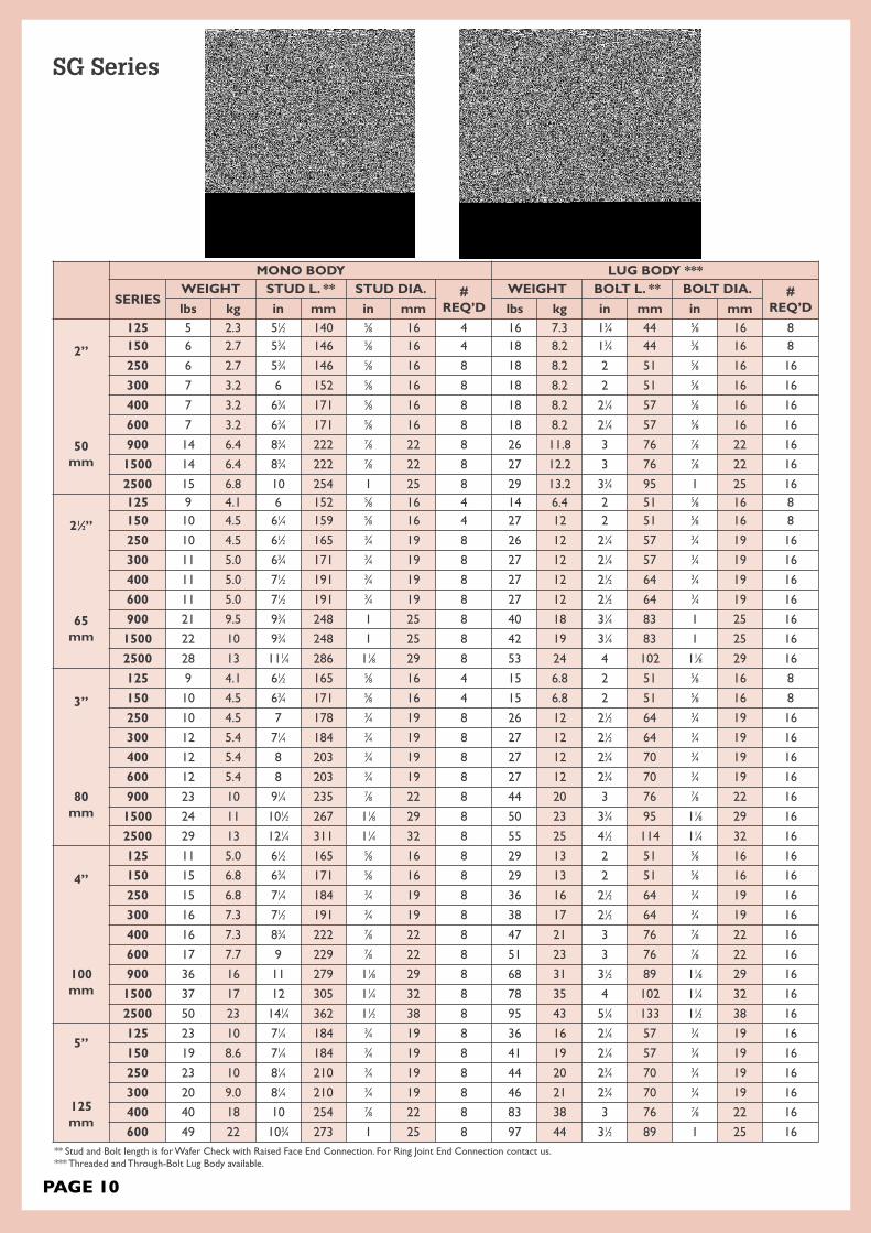
• †API 2000, 3000, 5000 available upon request.• 11⁄2” (40mm) Refer to drawings.• Dimensions for larger valve sizes available upon request.• Also available with JIS, DIN, BS, AS and ISO dimensions.• Approximate valve weight only.• ***Threaded and Through-Bolt Lugged Body available.
SG Series
PAGE 10
MONO BODY LUG BODY ***
SERIESWEIGHT STUD L. ** STUD DIA. #
REQ’DWEIGHT BOLT L. ** BOLT DIA. #
REQ’Dlbs kg in mm in mm lbs kg in mm in mm
2”
50mm
125 5 2.3 51⁄2 140 5⁄8 16 4 16 7.3 13⁄4 44 5⁄8 16 8150 6 2.7 53⁄4 146 5⁄8 16 4 18 8.2 13⁄4 44 5⁄8 16 8
250 6 2.7 53⁄4 146 5⁄8 16 8 18 8.2 2 51 5⁄8 16 16
300 7 3.2 6 152 5⁄8 16 8 18 8.2 2 51 5⁄8 16 16
400 7 3.2 63⁄4 171 5⁄8 16 8 18 8.2 21⁄4 57 5⁄8 16 16
600 7 3.2 63⁄4 171 5⁄8 16 8 18 8.2 21⁄4 57 5⁄8 16 16
900 14 6.4 83⁄4 222 7⁄8 22 8 26 11.8 3 76 7⁄8 22 16
1500 14 6.4 83⁄4 222 7⁄8 22 8 27 12.2 3 76 7⁄8 22 16
2500 15 6.8 10 254 1 25 8 29 13.2 33⁄4 95 1 25 16
21⁄2”
65mm
125 9 4.1 6 152 5⁄8 16 4 14 6.4 2 51 5⁄8 16 8150 10 4.5 61⁄4 159 5⁄8 16 4 27 12 2 51 5⁄8 16 8
250 10 4.5 61⁄2 165 3⁄4 19 8 26 12 21⁄4 57 3⁄4 19 16
300 11 5.0 63⁄4 171 3⁄4 19 8 27 12 21⁄4 57 3⁄4 19 16
400 11 5.0 71⁄2 191 3⁄4 19 8 27 12 21⁄2 64 3⁄4 19 16
600 11 5.0 71⁄2 191 3⁄4 19 8 27 12 21⁄2 64 3⁄4 19 16
900 21 9.5 93⁄4 248 1 25 8 40 18 31⁄4 83 1 25 16
1500 22 10 93⁄4 248 1 25 8 42 19 31⁄4 83 1 25 16
2500 28 13 111⁄4 286 11⁄8 29 8 53 24 4 102 11⁄8 29 16
3”
80mm
125 9 4.1 61⁄2 165 5⁄8 16 4 15 6.8 2 51 5⁄8 16 8
150 10 4.5 63⁄4 171 5⁄8 16 4 15 6.8 2 51 5⁄8 16 8
250 10 4.5 7 178 3⁄4 19 8 26 12 21⁄2 64 3⁄4 19 16
300 12 5.4 71⁄4 184 3⁄4 19 8 27 12 21⁄2 64 3⁄4 19 16
400 12 5.4 8 203 3⁄4 19 8 27 12 23⁄4 70 3⁄4 19 16
600 12 5.4 8 203 3⁄4 19 8 27 12 23⁄4 70 3⁄4 19 16
900 23 10 91⁄4 235 7⁄8 22 8 44 20 3 76 7⁄8 22 16
1500 24 11 101⁄2 267 11⁄8 29 8 50 23 33⁄4 95 11⁄8 29 16
2500 29 13 121⁄4 311 11⁄4 32 8 55 25 41⁄2 114 11⁄4 32 16
4”
100mm
125 11 5.0 61⁄2 165 5⁄8 16 8 29 13 2 51 5⁄8 16 16
150 15 6.8 63⁄4 171 5⁄8 16 8 29 13 2 51 5⁄8 16 16
250 15 6.8 71⁄4 184 3⁄4 19 8 36 16 21⁄2 64 3⁄4 19 16
300 16 7.3 71⁄2 191 3⁄4 19 8 38 17 21⁄2 64 3⁄4 19 16
400 16 7.3 83⁄4 222 7⁄8 22 8 47 21 3 76 7⁄8 22 16
600 17 7.7 9 229 7⁄8 22 8 51 23 3 76 7⁄8 22 16
900 36 16 11 279 11⁄8 29 8 68 31 31⁄2 89 11⁄8 29 16
1500 37 17 12 305 11⁄4 32 8 78 35 4 102 11⁄4 32 16
2500 50 23 141⁄4 362 11⁄2 38 8 95 43 51⁄4 133 11⁄2 38 16
5”
125mm
125 23 10 71⁄4 184 3⁄4 19 8 36 16 21⁄4 57 3⁄4 19 16
150 19 8.6 71⁄4 184 3⁄4 19 8 41 19 21⁄4 57 3⁄4 19 16
250 23 10 81⁄4 210 3⁄4 19 8 44 20 23⁄4 70 3⁄4 19 16
300 20 9.0 81⁄4 210 3⁄4 19 8 46 21 23⁄4 70 3⁄4 19 16
400 40 18 10 254 7⁄8 22 8 83 38 3 76 7⁄8 22 16
600 49 22 103⁄4 273 1 25 8 97 44 31⁄2 89 1 25 16** Stud and Bolt length is for Wafer Check with Raised Face End Connection. For Ring Joint End Connection contact us.*** Threaded and Through-Bolt Lug Body available.
SG Series

PAGE 11
6” - 16” / 150mm-400mm - vALvE DIMENSIONS
SERIESAD B C* D ER J
in mm in mm in mm in mm in mm in mm
6”
150mm
125 83⁄4 222 33⁄4 95 59⁄16 141 65⁄8 168 39⁄32 83 111⁄16 43150 83⁄4 222 37⁄8 98 59⁄16 141 65⁄8 168 39⁄32 83 111⁄16 43250 97⁄8 251 33⁄4 95 59⁄16 141 65⁄8 168 39⁄32 83 111⁄16 43300 97⁄8 251 37⁄8 98 59⁄16 141 65⁄8 168 39⁄32 83 111⁄16 43400 93⁄4 248 53⁄8 137 43⁄4 121 65⁄8 168 39⁄32 83 25⁄16 59600 101⁄2 267 53⁄8 137 43⁄4 121 65⁄8 168 39⁄32 83 25⁄16 59900 113⁄8 289 61⁄4 159 35⁄8 92 65⁄8 168 39⁄32 83 213⁄16 711500 111⁄8 283 61⁄4 159 35⁄8 92 65⁄8 168 39⁄32 83 213⁄16 712500 121⁄2 318 61⁄4 159 35⁄8 92 65⁄8 168 39⁄32 83 213⁄16 71
8”
200mm
125 11 279 5 127 71⁄2 191 85⁄8 219 41⁄4 108 23⁄16 56150 11 279 5 127 71⁄2 191 85⁄8 219 41⁄4 108 23⁄16 56250 121⁄8 308 5 127 71⁄2 191 85⁄8 219 41⁄4 108 23⁄16 56300 121⁄8 308 5 127 71⁄2 191 85⁄8 219 41⁄4 108 23⁄16 56400 12 305 61⁄2 165 71⁄2 191 85⁄8 219 41⁄4 108 21⁄2 64600 125⁄8 321 61⁄2 165 625⁄32 172 85⁄8 219 41⁄4 108 29⁄16 65900 141⁄8 359 81⁄8 206 61⁄2 165 85⁄8 219 41⁄4 108 27⁄8 731500 137⁄8 352 81⁄8 206 61⁄2 165 85⁄8 219 41⁄4 108 27⁄8 732500 151⁄4 387 81⁄8 206 61⁄16 155 85⁄8 219 41⁄4 108 3 76
10”
250mm
125 133⁄8 340 51⁄2 140 97⁄16 240 103⁄4 273 57⁄32 133 25⁄16 59150 133⁄8 340 53⁄4 146 97⁄16 240 103⁄4 273 57⁄32 133 25⁄16 59250 141⁄4 362 51⁄2 140 97⁄16 240 103⁄4 273 57⁄32 133 25⁄16 59300 141⁄4 362 53⁄4 146 97⁄16 240 103⁄4 273 57⁄32 133 25⁄16 59400 141⁄8 359 83⁄8 213 81⁄2 216 103⁄4 273 57⁄32 133 33⁄16 81600 153⁄4 400 83⁄8 213 81⁄2 216 103⁄4 273 57⁄32 133 33⁄16 81900 171⁄8 435 91⁄2 241 83⁄16 208 103⁄4 273 57⁄32 133 33⁄8 861500 171⁄8 435 93⁄4 248 8 203 103⁄4 273 57⁄32 133 31⁄2 892500 183⁄4 476 10 254 61⁄2 165 103⁄4 273 57⁄32 133 43⁄16 106
12”
300mm
125 161⁄8 410 71⁄8 181 111⁄4 286 127⁄8 327 63⁄8 162 31⁄4 83150 161⁄8 410 71⁄8 181 111⁄4 286 127⁄8 327 63⁄8 162 31⁄4 83250 165⁄8 422 71⁄8 181 111⁄4 286 127⁄8 327 63⁄8 162 31⁄4 83300 165⁄8 422 71⁄8 181 111⁄4 286 127⁄8 327 63⁄8 162 31⁄4 83400 161⁄2 419 9 229 109⁄16 268 127⁄8 327 63⁄8 162 35⁄8 92600 18 457 9 229 109⁄16 268 127⁄8 327 63⁄8 162 35⁄8 92900 195⁄8 498 111⁄2 292 93⁄4 248 127⁄8 327 63⁄8 162 41⁄4 1081500 201⁄2 521 12 305 91⁄4 235 127⁄8 327 63⁄8 162 41⁄2 1142500 215⁄8 549 12 305 91⁄4 235 127⁄8 327 63⁄8 162 41⁄2 114
14”
350mm
125 173⁄4 451 71⁄4 184 125⁄8 321 14 356 67⁄8 175 3 76150 173⁄4 451 71⁄4 184 125⁄8 321 14 356 67⁄8 175 3 76250 191⁄8 486 83⁄4 222 127⁄16 316 14 356 67⁄8 175 33⁄16 81300 191⁄8 486 83⁄4 222 127⁄16 316 14 356 67⁄8 175 33⁄16 81400 19 483 103⁄4 273 1115⁄16 303 14 356 615⁄16 176 35⁄8 92600 193⁄8 492 103⁄4 273 1115⁄16 303 14 356 615⁄16 176 33⁄8 86900 201⁄2 521 14 356 815⁄16 227 14 356 615⁄16 177 51⁄2 1401500 223⁄4 578 14 356 815⁄16 227 14 356 615⁄16 177 51⁄2 140
16”
400mm
125 201⁄4 514 71⁄2 191 1411⁄16 373 16 406 723⁄32 196 21⁄2 64150 201⁄4 514 71⁄2 191 1411⁄16 373 16 406 723⁄32 196 21⁄2 64250 211⁄4 540 91⁄8 232 141⁄2 368 16 406 723⁄32 196 3 76300 211⁄4 540 91⁄8 232 141⁄2 368 16 406 723⁄32 196 3 76400 211⁄8 537 12 305 131⁄2 343 16 406 725⁄32 198 41⁄4 108600 221⁄4 565 12 305 131⁄2 343 16 406 725⁄32 198 41⁄4 108900 225⁄8 575 151⁄8 384 117⁄32 286 16 406 713⁄16 199 55⁄8 1431500 251⁄4 641 151⁄8 384 117⁄32 286 16 406 713⁄16 199 55⁄8 143
* Minimum Flange Bore
ANSI INSTALLATION DIMENSIONS†
• †API 2000, 3000, 5000 available upon request• 11⁄2” (40mm) Refer to drawings.• Dimensions for larger valve sizes available upon request.• Also available with JIS, DIN, BS, AS and ISO dimensions.• Approximate valve weight only.• ***Threaded and Through-Bolt Lugged Body available
SG Series

MONO BODY LUG BODY ***
SERIESWEIGHT STUD L. ** STUD DIA. #
REQ’DWEIGHT BOLT L. ** BOLT DIA. #
REQ’Dlbs kg in mm in mm lbs kg in mm in mm
6”
150mm
125 28 13 8 203 3⁄4 19 8 41 19 21⁄4 57 3⁄4 19 16150 30 14 8 203 3⁄4 19 8 51 23 21⁄4 57 3⁄4 19 16250 35 16 83⁄4 222 3⁄4 19 12 78 35 23⁄4 70 3⁄4 19 24300 36 16 9 229 3⁄4 19 12 81 37 23⁄4 70 3⁄4 19 24400 64 29 111⁄2 292 7⁄8 22 12 140 64 31⁄4 83 7⁄8 22 24600 65 30 121⁄4 311 1 25 12 151 69 31⁄2 89 1 25 24900 115 52 14 356 11⁄8 29 12 240 109 4 102 11⁄8 29 241500 121 55 163⁄4 425 13⁄8 35 12 242 110 51⁄4 133 13⁄8 35 242500 132 60 20 508 2 51 8 251 114 7 178 2 51 16
8”
200mm
125 49 22 91⁄2 241 3⁄4 19 8 88 40 21⁄2 64 3⁄4 19 16150 50 23 91⁄2 241 3⁄4 19 8 91 41 21⁄2 64 3⁄4 19 16250 67 30 103⁄4 273 7⁄8 22 12 141 64 3 76 7⁄8 22 24300 69 31 103⁄4 273 7⁄8 25 12 151 69 31⁄4 83 1 25 24400 105 48 131⁄2 343 1 29 12 237 108 33⁄4 95 11⁄8 29 24600 115 52 141⁄4 362 11⁄8 29 12 261 119 4 102 11⁄8 29 24900 252 115 17 432 13⁄8 35 12 443 201 41⁄2 114 13⁄8 35 241500 205 93 193⁄4 502 15⁄8 41 12 401 182 6 152 15⁄8 41 242500 257 117 231⁄2 597 2 51 12 461 210 73⁄4 197 2 51 24
10”
250mm
125 83 38 101⁄4 260 7⁄8 22 12 136 62 21⁄2 64 7⁄8 22 24150 92 42 101⁄2 267 7⁄8 22 12 151 69 21⁄2 64 7⁄8 22 24250 107 49 12 305 1 25 16 236 107 31⁄2 89 1 25 32300 93 42 121⁄4 311 1 25 16 251 114 31⁄2 89 1 25 32400 210 95 16 406 11⁄8 29 16 431 196 4 102 11⁄8 29 32600 209 95 17 432 11⁄4 32 16 460 209 41⁄2 114 11⁄4 32 32900 348 158 19 483 13⁄8 35 16 661 300 43⁄4 121 13⁄8 35 321500 378 172 231⁄4 591 17⁄8 48 12 711 323 63⁄4 171 17⁄8 48 242500 466 212 291⁄2 749 21⁄2 64 12 751 341 93⁄4 248 21⁄2 64 24
12”
300mm
125 149 68 12 305 7⁄8 22 12 248 113 23⁄4 70 7⁄8 22 24150 156 71 12 305 7⁄8 22 12 241 110 23⁄4 70 7⁄8 22 24250 166 75 14 356 11⁄8 29 16 330 150 33⁄4 95 11⁄8 29 32300 139 63 14 356 11⁄8 29 16 342 155 33⁄4 95 11⁄8 29 32400 255 116 171⁄4 438 11⁄4 32 16 451 205 41⁄4 108 11⁄4 32 32600 264 120 18 457 11⁄4 32 20 587 267 41⁄2 114 11⁄4 32 40900 490 223 213⁄4 552 13⁄8 35 20 981 446 51⁄4 133 13⁄8 35 401500 540 245 27 686 2 51 16 972 442 71⁄2 191 2 51 322500 678 308 331⁄2 851 23⁄4 70 12 1118 508 103⁄4 273 23⁄4 70 24
14”
350mm
125 183 83 123⁄4 324 1 25 12 271 123 3 76 1 25 24150 210 95 123⁄4 324 1 25 12 291 132 3 76 1 25 24250 285 130 16 406 11⁄8 29 20 504 229 33⁄4 95 11⁄8 29 40300 270 123 16 406 11⁄8 29 20 543 246 33⁄4 95 11⁄8 29 40400 440 200 191⁄4 489 11⁄4 32 20 792 360 41⁄4 108 11⁄4 32 40600 430 195 201⁄4 514 13⁄8 35 20 817 371 43⁄4 121 13⁄8 35 40900 926 421 25 635 11⁄2 38 20 1241 564 51⁄2 140 11⁄2 38 401500 948 431 301⁄4 768 21⁄4 57 16 1659 754 81⁄4 210 21⁄4 57 32
16”
400mm
125 213 97 13 330 1 25 16 441 200 3 76 1 25 32150 214 97 13 330 1 25 16 464 211 3 76 1 25 32250 375 170 163⁄4 425 11⁄4 32 20 761 346 41⁄4 108 11⁄4 32 40300 356 162 163⁄4 425 11⁄4 32 20 792 360 41⁄4 108 11⁄4 32 40400 510 232 21 533 13⁄8 35 20 1046 475 41⁄2 114 13⁄8 35 40600 504 229 221⁄4 565 11⁄2 38 20 1058 481 51⁄4 133 11⁄2 38 40900 1152 524 261⁄2 673 15⁄8 41 20 2074 943 53⁄4 146 15⁄8 41 401500 1380 627 323⁄4 832 21⁄2 64 16 2277 1035 9 229 21⁄2 64 32
** Stud and Bolt length is for Wafer Check with Raised Face End Connection. For Ring Joint End Connection contact us. *** Threaded and Through-Bolt Lug Body available.
PAGE 12
SG Series
PAGE 13
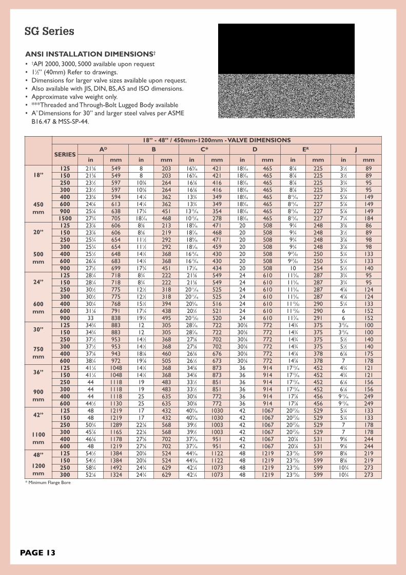
18” - 48” / 450mm-1200mm - vALvE DIMENSIONS
SERIESAD B C* D ER J
in mm in mm in mm in mm in mm in mm
18”
450mm
125 215⁄8 549 8 203 169⁄16 421 185⁄16 465 87⁄8 225 31⁄2 89150 215⁄8 549 8 203 169⁄16 421 185⁄16 465 87⁄8 225 31⁄2 89250 231⁄2 597 103⁄8 264 163⁄8 416 185⁄16 465 87⁄8 225 33⁄4 95300 231⁄2 597 103⁄8 264 163⁄8 416 185⁄16 465 87⁄8 225 33⁄4 95400 233⁄8 594 141⁄4 362 133⁄4 349 185⁄16 465 815⁄16 227 57⁄8 149600 241⁄8 613 141⁄4 362 133⁄4 349 185⁄16 465 815⁄16 227 57⁄8 149900 251⁄8 638 173⁄4 451 1315⁄16 354 185⁄16 465 815⁄16 227 57⁄8 1491500 273⁄4 705 187⁄16 468 1015⁄16 278 185⁄16 465 815⁄16 227 71⁄4 184
20”
500mm
125 237⁄8 606 83⁄8 213 189⁄16 471 20 508 93⁄4 248 33⁄8 86150 237⁄8 606 85⁄8 219 187⁄16 468 20 508 93⁄4 248 31⁄2 89250 253⁄4 654 111⁄2 292 189⁄16 471 20 508 93⁄4 248 37⁄8 98300 253⁄4 654 111⁄2 292 181⁄16 459 20 508 93⁄4 248 37⁄8 98400 251⁄2 648 141⁄2 368 1615⁄16 430 20 508 927⁄32 250 51⁄4 133600 267⁄8 683 141⁄2 368 1615⁄16 430 20 508 927⁄32 250 51⁄4 133900 271⁄2 699 173⁄4 451 171⁄16 434 20 508 10 254 51⁄2 140
24”
600mm
125 281⁄4 718 83⁄4 222 215⁄8 549 24 610 115⁄16 287 33⁄4 95150 281⁄4 718 83⁄4 222 215⁄8 549 24 610 115⁄16 287 33⁄4 95250 301⁄2 775 121⁄2 318 2011⁄16 525 24 610 115⁄16 287 47⁄8 124300 301⁄2 775 121⁄2 318 2011⁄16 525 24 610 115⁄16 287 47⁄8 124400 301⁄4 768 151⁄2 394 205⁄16 516 24 610 1113⁄32 290 51⁄4 133600 311⁄8 791 171⁄4 438 201⁄2 521 24 610 1113⁄32 290 6 152900 33 838 191⁄2 495 2015⁄32 520 24 610 117⁄16 291 6 152
30”
750mm
125 343⁄4 883 12 305 287⁄16 722 303⁄8 772 143⁄4 375 315⁄16 100150 343⁄4 883 12 305 287⁄16 722 303⁄8 772 143⁄4 375 315⁄16 100250 371⁄2 953 141⁄2 368 275⁄8 702 303⁄8 772 143⁄4 375 51⁄2 140300 371⁄2 953 141⁄2 368 275⁄8 702 303⁄8 772 143⁄4 375 51⁄2 140400 371⁄8 943 181⁄8 460 265⁄8 676 303⁄8 772 147⁄8 378 67⁄8 175600 381⁄4 972 197⁄8 505 261⁄2 673 303⁄8 772 147⁄8 378 7 178
36”
900mm
125 411⁄4 1048 141⁄2 368 343⁄8 873 36 914 1713⁄16 452 43⁄4 121150 411⁄4 1048 141⁄2 368 343⁄8 873 36 914 1713⁄16 452 43⁄4 121250 44 1118 19 483 331⁄2 851 36 914 1713⁄16 452 61⁄8 156300 44 1118 19 483 331⁄2 851 36 914 1713⁄16 452 61⁄8 156400 44 1118 25 635 303⁄8 772 36 914 177⁄8 456 913⁄16 249600 441⁄2 1130 25 635 303⁄8 772 36 914 177⁄8 456 913⁄16 249
42”
1100mm
125 48 1219 17 432 409⁄16 1030 42 1067 2027⁄32 529 51⁄4 133150 48 1219 17 432 409⁄16 1030 42 1067 2027⁄32 529 51⁄4 133250 503⁄4 1289 223⁄8 568 391⁄2 1003 42 1067 2027⁄32 529 7 178300 457⁄8 1165 223⁄8 568 391⁄2 1003 42 1067 2027⁄32 529 7 178400 463⁄8 1178 275⁄8 702 377⁄16 951 42 1067 207⁄8 531 95⁄8 244600 48 1219 275⁄8 702 377⁄16 951 42 1067 207⁄8 531 95⁄8 244
48”
1200mm
125 541⁄2 1384 205⁄8 524 443⁄16 1122 48 1219 2319⁄32 599 85⁄8 219150 541⁄2 1384 205⁄8 524 443⁄16 1122 48 1219 2319⁄32 599 85⁄8 219250 583⁄4 1492 243⁄4 629 421⁄4 1073 48 1219 2319⁄32 599 103⁄4 273300 521⁄8 1324 243⁄4 629 421⁄4 1073 48 1219 2319⁄32 599 103⁄4 273
* Minimum Flange Bore
ANSI INSTALLATION DIMENSIONS†
• †API 2000, 3000, 5000 available upon request• 11⁄2” (40mm) Refer to drawings.• Dimensions for larger valve sizes available upon request.• Also available with JIS, DIN, BS, AS and ISO dimensions.• Approximate valve weight only.• ***Threaded and Through-Bolt Lugged Body available• AD Dimensions for 30” and larger steel valves per ASMEB16.47 & MSS-SP-44.
SG Series

PAGE 14
MONO BODY FLANGE BODY ***
SERIESWEIGHT STUD L. ** STUD DIA. #
REQ’DWEIGHT BOLT L. ** BOLT DIA. #
REQ’Dlbs kg in mm in mm lbs kg in mm in mm
18”
450mm
125 305 138 14 356 11⁄8 29 16 419 190 31⁄4 83 11⁄8 29 32150 308 140 14 356 11⁄8 29 16 431 196 31⁄4 83 11⁄8 29 32250 470 213 181⁄4 464 11⁄4 32 24 623 283 4 102 11⁄4 32 48300 500 227 181⁄4 464 11⁄4 32 24 651 295 4 102 11⁄4 32 48400 710 322 231⁄2 597 13⁄8 35 24 981 445 41⁄2 114 13⁄8 35 48600 740 336 251⁄4 641 15⁄8 41 20 1011 459 51⁄2 140 15⁄8 41 40900 1039 471 303⁄4 781 17⁄8 48 20 1418 643 61⁄2 165 17⁄8 48 401500 1621 735 381⁄4 972 23⁄4 70 16 2551 1157 93⁄4 248 23⁄4 70 32
20”
500mm
125 338 153 143⁄4 375 11⁄8 29 20 488 221 31⁄4 83 11⁄8 29 40150 357 162 15 381 11⁄8 29 20 501 227 31⁄4 83 11⁄8 29 40250 590 268 193⁄4 502 11⁄4 32 24 757 343 41⁄4 108 11⁄4 32 48300 590 268 193⁄4 502 11⁄4 32 24 780 354 41⁄4 108 11⁄4 32 48400 841 382 241⁄4 616 11⁄2 38 24 1191 540 43⁄4 121 11⁄2 38 48600 980 445 26 660 15⁄8 41 24 1279 580 53⁄4 146 15⁄8 41 48900 1421 645 313⁄4 806 2 51 20 1892 858 63⁄4 171 2 51 40
24”
600mm
125 522 237 153⁄4 400 11⁄4 32 20 657 298 31⁄2 89 11⁄4 32 40150 500 227 153⁄4 400 11⁄4 32 20 682 309 31⁄2 89 11⁄4 32 40250 690 313 213⁄4 552 11⁄2 38 24 981 445 43⁄4 121 11⁄2 38 48300 727 330 213⁄4 552 11⁄2 38 24 1011 459 43⁄4 121 11⁄2 38 48400 1200 544 261⁄4 667 13⁄4 44 24 1551 704 51⁄4 133 13⁄4 44 48600 1445 656 301⁄2 775 17⁄8 48 24 1851 840 61⁄2 165 17⁄8 48 48900 1900 862 37 940 21⁄2 64 20 2786 1264 81⁄2 216 21⁄2 64 40
30”
750mm
125 1135 515 211⁄4 540 11⁄4 32 28 1273 577 43⁄4 121 11⁄4 32 56150 1100 499 211⁄4 540 11⁄4 32 28 1321 599 43⁄4 121 11⁄4 32 56250 1400 635 261⁄2 673 13⁄4 44 28 1883 854 53⁄4 146 13⁄4 44 56300 1500 680 261⁄2 673 13⁄4 44 28 1974 895 53⁄4 146 13⁄4 44 56400 2500 1135 311⁄2 800 2 51 28 2773 1258 61⁄2 165 2 51 56600 2640 1199 341⁄4 870 2 51 28 2987 1355 7 178 2 51 56
36”
900mm
125 1457 661 251⁄2 648 11⁄2 38 32 1811 821 51⁄2 140 11⁄2 38 64150 1520 690 251⁄2 648 11⁄2 38 32 1898 861 51⁄2 140 11⁄2 38 64250 3050 1384 321⁄4 819 2 51 32 3811 1729 61⁄2 165 2 51 64300 3200 1452 321⁄4 819 2 51 32 3926 1781 61⁄2 165 2 51 64400 4070 1846 391⁄4 997 2 51 32 5241 2377 7 178 2 51 64600 4200 1905 41 1041 21⁄2 64 28 5364 2433 8 203 21⁄2 64 56
42”
1100mm
125 2700 1225 283⁄4 730 11⁄2 38 36 3179 1442 6 152 11⁄2 38 72150 2800 1270 283⁄4 730 11⁄2 38 36 3236 1468 6 152 11⁄2 38 72250 3830 1738 37 940 2 51 36 4651 2110 71⁄4 184 2 51 72300 4000 1815 37 940 2 51 36 4830 2191 71⁄4 184 2 51 72400 5650 2563 431⁄4 1099 17⁄8 48 32 6921 3139 73⁄4 197 17⁄8 48 64600 5800 2631 47 1194 21⁄2 64 28 7048 3197 93⁄4 248 21⁄2 64 56
48”
1200mm
125 3900 1769 331⁄4 845 11⁄2 38 44 4711 2137 61⁄4 159 11⁄2 38 88150 4400 1996 331⁄4 845 11⁄2 38 44 4899 2219 61⁄4 159 11⁄2 38 88250 5500 2495 401⁄2 1029 2 51 40 6477 2938 73⁄4 197 2 51 80300 5700 2586 401⁄2 1029 2 51 40 6653 3018 73⁄4 197 2 51 80
** Stud and Bolt length is for Raised Face End Connection. For Ring Joint End Connection contact us.
SG Series

PAGE 15 ®
Style Body and Plates*
Rating
Seat
Ends
Body Type
Modifier for Alternate plates(flaps) and seat overlay
Spring Material3
5
2
6
41
9
7
1 2 3 4 5 6 7 8 9
Other Trim Material (hinge pin, stop pin)
8
Part Number System Dual Flap Check
* Body & plate are same material unless partnumber modified suffix (9) indicates differentplate material.
*Modifier suffix (9) indicates specialoverlay materials. P Seat is ‘as body’ ifno modifier suffix.
SG Standard Design.
GW Retainerless Design
12 ANSI Class 125
15 ANSI Class 150
25 ANSI Class 250
30 ANSI Class 300
40 ANSI Class 400
60 ANSI Class 600
90 ANSI Class 900
150 ANSI Class 1500
250 ANSI Class 2500
21 API 2000
31 API 3000
51 API 5000
101 API 10000
151 API 15000
BD12 BS Table D
BE12 BS Table E
BF BS Table F
BH BS Table H
BJ BS Table J
6 DIN/JIS PN06
10 DIN/JIS PN10
16 DIN/JIS PN16
25 DIN/JIS PN25
40 DIN/JIS PN40
A 4130/4140/A487 4C (API6A)
B Aluminium Bronze
C 316/CF8M Stainless Steel
D 304/CF8 Stainless Steel
E 410/F6A/CA15 Stainless Steel
F Alloy 20
G Low Temp. C.S. LF2/LCB
H Cast Iron
HD Ductile Iron
M Monel
S Carbon Steel A105/WCB
T 317 SS
U WC6 Alloy Steel
V 347 SS
W 316L SS/CF3M
X WC9 Alloy Steel
Y C5 Alloy Steel
AF F6A Stainless Steel
CA CD3MN/4A Duplex SS
DZ F51 Duplex/S31803 SS
FN Inconel®
GC LCC Low Temp. Steel
SC WCC Steel
TT Titanium
Z Special
A EPDM
H HNBR
M Buna/NBR/Nitrile
N Neoprene
P Metal*
V Viton B
Z Special
F Raised Face (serrated)*G Graylock® Hub
P Plain Face
R Ring Joint
W Buttweld
None Wafer Style
(Blank)
1 Lugged & Tapped
2 Lugged Through Bolt
3 Double Flanged Through Bolt
4 Double Flanged Tapped
1 304 SS Plates
2 AL Bronze Plates
3 Ductile Iron Plates
4 316 SS Plates
39 410 SS Plates
40 410 Plates, Stellite overlay Seat
41A 316 Plates, Stellite Seat & Plates
42B 316 Plates, Stellite overlay Seat
61A 410 Plates, Stellite Seat & Plates
72A WCB Plates, Stellite Seat & Plates
72B WCB Plates, Stellite overlay Seat
88 316 Plates, 316 overlay Seat
169 410 Plates, 410 overlay Seat
999 Special
4 316 SS
5 304 SS
6 Aluminium Bronze
8 Inconel 600
9 Inconel X750
1 304 SS
3 F51/ UNS S31803
4 316 SS
5 410 SS
8 AL-Bronze
9 A20
SG 30 S M F 1 - 4 4 - 61A
SG Series

Wafer Check Dual FlapSteel Body
PAGE 16
• Retainerless design meets fugitive emission requirements as there areno threaded plugs in the pressure boundary, thus eliminating potentialleak paths.
• Face to face to API-594, wall thickness & design to API594, test & inspection to API598, flanging to ANSI B16.5
• Vertical or Horizontal installation.• Intrinsically Firesafe• Very low head loss & minimum occupation of space.• Suitable to fit between ANSI 150,300,600,900,1500 & 2500 flanges aswell as API3000, 5000, BS, AS, JIS, DIN etc
• Service Pressure150 class 20 Bar (285 PSI)300 class 51.1 Bar (740 PSI)600 class 102.1 Bar (1480 PSI)900 class 153.2 Bar (2220 PSI)1500 class 255.3 Bar (3705 PSI)2500 class 425.5 Bar (6170 PSI)
• ALLEvIATION from WATER HAMMERReaction of torsion spring makes plates rapidly close prior to the start of reverse flow of fluid due to the cessation of power, thus preventing pumpand other devices from causing damage due to Water Hammering.
• LOWER HEAD LOSSDesigned with optimum venturi to reduce head loss and is comparable withsimilar Dual Plate type Check Valves.
CHARACTERISTICS
DESIGN FEATURES
FIG# GW 15 GW 30 GW 60 GW 90 GW 150 GW 250
*Seat types:- As per body, F6NM, HF, CR13, 316† For other available trim configurations refer part number system.
Trim# Body (1) Plates (2) Seat (11) Spring (3) Stop (5) & Hinge Pins (4)
Body plate & SpringBearings (7/9)
SVF WCB WCB / CR13 / 304 / 316 Viton 316 or Inconel 316 SS / CR13 PTFE / SS
SPF WCB WCB / CR13 / 304 / 316 Metal* 316 or Inconel 316 SS / CR13 PTFE / SS
SVF WCB WCB / CR13 / 304 / 316 Viton 316 or Inconel 316 SS / CR13 PTFE / SS
SMF WCB WCB / CR13 / 304 / 316 Buna-NBR 316 or Inconel 316 SS / CR13 PTFE / SS
DMF CF8 (304 SS) 304 SS Buna-NBR 304 or Inconel 304 SS PTFE / SS
DPF CF8 (304 SS) 304 SS Metal* 316 or Inconel 316 SS PTFE / SS
DVF CF8 (304 SS) 304 SS Viton 316 or Inconel 316 SS PTFE / SS
CPF CF8M (316 SS) 316 SS Metal* 316 or Inconel 316 SS PTFE / SS
CVF CF8M (316 SS) 316 SS Viton 316 or Inconel 316 SS PTFE / SS
STANDARD TRIM (WETTED PARTS) CONFIGURATIONS†
11
GW Series - Retainerless Fugitive Emission

PAGE 17
SUPERCHECK is a non-slam check valve because it operates on flowcessation, not flow reversal. The normal position of the plates isclosed, held against the seat by the unique spring design. As flow begins, the heels of the two plates are lifted off the seat face on thecentral rib.The cracking pressure is less than 3 psi across most of the range(larger sizes and higher classes are slightly higher). As flow increases,the plates then pivot against the spring pressure. Since the heels havealready lifted off the rib seat there is no scrub or wear, either on therib, body or plate seating surfaces. A pressure of only 4 psi is required to keep the plates fully open in 150 class, slightly higher inother classes. (“Light” springs also available)When flow stops and pressure ceases the spring closes the plates.Flow reversal is then stopped by the closed Supercheck valve and anyback pressure only serves to make the valve seal more tightly.
NON-SLAM
INSTALLATIONIn addition to the compact shape, SUPER-CHECK Valves canbe installed either horizontally or vertically.
Operating Temperature Range for Seal Materials
Material Operating Temperature °C
EPDM - 25 to 110
Buna-N - 30 to 100
Neoprene - 10 to 80
Metal* - 267 to 537 (As Body)
viton-B - 29 to 200
The temperature range is a general guide. As temperature increase thepressure rating of the valve decreases. Ask for pressure/temperaturechart. *Dependant on body material.
Spring Temperature
Spring Material Maximum Temperature °C
Type 316SS 120
Inconel x 750 (Heat treated) 537
END TYPES
GW Series
➡ ➡
➡➡
RaisedFace(serrated)
RingJoint
PlainFace
ØA
ØD
B

PAGE 18
ANSI INSTALLATION DIMENSIONS†
• † API 2000, 3000, 5000 available upon request• 11⁄2” (40mm) Refer to drawings.• Dimensions for larger valve sizes available upon request.• Also available with JIS, DIN, BS, AS and ISO dimensions.• Approximate valve weight only.• ***Threaded and Through-Bolt Lugged Body available
2” - 5” / 50mm-125mm - vALvE DIMENSIONS
SERIESAD B C* D ER J
in mm in mm in mm in mm in mm in mm
2”
50mm
125 41⁄8 105 21⁄8 54 11⁄2 38 23⁄8 60 15⁄32 29 15⁄16 24
150 41⁄8 105 23⁄8 60 13⁄16 30 23⁄8 60 15⁄32 29 7⁄8 22
250 43⁄8 111 21⁄8 54 11⁄2 38 23⁄8 60 15⁄32 29 15⁄16 24
300 43⁄8 111 23⁄8 60 13⁄16 30 23⁄8 60 15⁄32 29 7⁄8 22
400 43⁄8 111 23⁄8 60 13⁄16 30 23⁄8 60 15⁄32 29 7⁄8 22
600 43⁄8 111 23⁄8 60 13⁄16 30 23⁄8 60 15⁄32 29 7⁄8 22
900 55⁄8 143 23⁄4 70 0 0 23⁄8 60 15⁄32 29 13⁄16 30
1500 55⁄8 143 23⁄4 70 0 0 23⁄8 60 15⁄32 29 13⁄16 30
2500 53⁄4 146 23⁄4 70 0 0 23⁄8 60 15⁄32 29 13⁄16 30
21⁄2”
65mm
125 47⁄8 124 23⁄8 60 27⁄32 56 27⁄8 73 115⁄32 37 1 25
150 47⁄8 124 25⁄8 67 21⁄8 54 27⁄8 73 115⁄32 37 11⁄8 29
250 51⁄8 130 23⁄8 60 27⁄32 56 27⁄8 73 115⁄32 37 1 25
300 51⁄8 130 25⁄8 67 21⁄8 54 27⁄8 73 115⁄32 37 11⁄8 29
400 51⁄8 130 25⁄8 67 21⁄8 54 27⁄8 73 115⁄32 37 11⁄8 29
600 51⁄8 130 25⁄8 67 21⁄8 54 27⁄8 73 115⁄32 37 11⁄8 29
900 61⁄2 165 31⁄4 83 2 51 27⁄8 73 115⁄32 37 13⁄16 30
1500 61⁄2 165 31⁄4 83 2 51 27⁄8 73 115⁄32 37 13⁄16 30
2500 65⁄8 168 31⁄4 83 2 51 27⁄8 73 115⁄32 37 13⁄16 30
3”
80mm
125 53⁄8 137 25⁄8 67 225⁄32 71 35⁄8 92 13⁄4 44 11⁄16 27
150 53⁄8 137 27⁄8 73 23⁄4 70 35⁄8 92 13⁄4 44 13⁄16 30
250 57⁄8 149 25⁄8 67 225⁄32 71 35⁄8 92 13⁄4 44 11⁄16 27
300 57⁄8 149 27⁄8 73 23⁄16 56 35⁄8 92 13⁄4 44 13⁄16 30
400 57⁄8 149 27⁄8 73 23⁄16 56 35⁄8 92 13⁄4 44 13⁄16 30
600 57⁄8 149 27⁄8 73 23⁄16 56 35⁄8 92 13⁄4 44 13⁄16 30
900 65⁄8 168 31⁄4 83 21⁄8 54 35⁄8 92 13⁄4 44 17⁄16 37
1500 67⁄8 175 31⁄4 83 21⁄8 54 35⁄8 92 13⁄4 44 17⁄16 37
2500 73⁄4 197 33⁄8 86 21⁄8 54 35⁄8 92 13⁄4 44 17⁄16 37
4”
100mm
125 67⁄8 175 25⁄8 67 323⁄32 94 45⁄8 117 25⁄16 59 13⁄8 35
150 67⁄8 175 27⁄8 73 311⁄16 94 45⁄8 117 25⁄16 59 17⁄16 37
250 71⁄8 181 25⁄8 67 323⁄32 94 45⁄8 117 25⁄16 59 13⁄8 35
300 71⁄8 181 27⁄8 73 311⁄16 94 45⁄8 117 25⁄16 59 17⁄16 37
400 7 178 31⁄8 79 35⁄16 85 45⁄8 117 25⁄16 59 15⁄8 41
600 75⁄8 194 31⁄8 79 35⁄16 85 45⁄8 117 25⁄16 59 15⁄8 41
900 81⁄8 206 4 102 31⁄16 78 45⁄8 117 25⁄16 59 13⁄4 44
1500 81⁄4 210 4 102 31⁄16 78 45⁄8 117 25⁄16 59 13⁄4 44
2500 91⁄4 235 41⁄8 105 31⁄16 78 45⁄8 117 25⁄16 59 13⁄4 44
5”
125mm
125 73⁄4 197 31⁄4 83 45⁄8 117 55⁄8 143 211⁄16 68 13⁄8 35
150 73⁄4 197 31⁄4 83 45⁄8 117 55⁄8 143 211⁄16 68 13⁄8 35
250 81⁄2 216 31⁄4 83 45⁄8 117 55⁄8 143 211⁄16 68 13⁄8 35
300 81⁄2 216 31⁄4 83 45⁄8 117 55⁄8 143 211⁄16 68 13⁄8 35
400 83⁄8 213 41⁄8 105 41⁄2 114 55⁄8 143 211⁄16 68 13⁄4 44
600 91⁄2 241 41⁄8 105 41⁄2 114 55⁄8 143 211⁄16 68 13⁄4 44* Minimum Flange Bore
GW Series

PAGE 19
MONO BODY LUG BODY ***
SERIESWEIGHT STUD L. ** STUD DIA. #
REQ’DWEIGHT BOLT L. ** BOLT DIA. #
REQ’Dlbs kg in mm in mm lbs kg in mm in mm
2”
50mm
125 5 2.3 51⁄2 140 5⁄8 16 4 16 7.3 13⁄4 44 5⁄8 16 8150 6 2.7 53⁄4 146 5⁄8 16 4 18 8.2 13⁄4 44 5⁄8 16 8
250 6 2.7 53⁄4 146 5⁄8 16 8 18 8.2 2 51 5⁄8 16 16
300 7 3.2 6 152 5⁄8 16 8 18 8.2 2 51 5⁄8 16 16
400 7 3.2 63⁄4 171 5⁄8 16 8 18 8.2 21⁄4 57 5⁄8 16 16
600 7 3.2 63⁄4 171 5⁄8 16 8 18 8.2 21⁄4 57 5⁄8 16 16
900 14 6.4 83⁄4 222 7⁄8 22 8 26 11.8 3 76 7⁄8 22 16
1500 14 6.4 83⁄4 222 7⁄8 22 8 27 12.2 3 76 7⁄8 22 16
2500 15 6.8 10 254 1 25 8 29 13.2 33⁄4 95 1 25 16
21⁄2”
65mm
125 9 4.1 6 152 5⁄8 16 4 14 6.4 2 51 5⁄8 16 8150 10 4.5 61⁄4 159 5⁄8 16 4 27 12 2 51 5⁄8 16 8
250 10 4.5 61⁄2 165 3⁄4 19 8 26 12 21⁄4 57 3⁄4 19 16
300 11 5.0 63⁄4 171 3⁄4 19 8 27 12 21⁄4 57 3⁄4 19 16
400 11 5.0 71⁄2 191 3⁄4 19 8 27 12 21⁄2 64 3⁄4 19 16
600 11 5.0 71⁄2 191 3⁄4 19 8 27 12 21⁄2 64 3⁄4 19 16
900 21 9.5 93⁄4 248 1 25 8 40 18 31⁄4 83 1 25 16
1500 22 10 93⁄4 248 1 25 8 42 19 31⁄4 83 1 25 16
2500 28 13 111⁄4 286 11⁄8 29 8 53 24 4 102 11⁄8 29 16
3”
80mm
125 9 4.1 61⁄2 165 5⁄8 16 4 15 6.8 2 51 5⁄8 16 8
150 10 4.5 63⁄4 171 5⁄8 16 4 15 6.8 2 51 5⁄8 16 8
250 10 4.5 7 178 3⁄4 19 8 26 12 21⁄2 64 3⁄4 19 16
300 12 5.4 71⁄4 184 3⁄4 19 8 27 12 21⁄2 64 3⁄4 19 16
400 12 5.4 8 203 3⁄4 19 8 27 12 23⁄4 70 3⁄4 19 16
600 12 5.4 8 203 3⁄4 19 8 27 12 23⁄4 70 3⁄4 19 16
900 23 10 91⁄4 235 7⁄8 22 8 44 20 3 76 7⁄8 22 16
1500 24 11 101⁄2 267 11⁄8 29 8 50 23 33⁄4 95 11⁄8 29 16
2500 29 13 121⁄4 311 11⁄4 32 8 55 25 41⁄2 114 11⁄4 32 16
4”
100mm
125 11 5.0 61⁄2 165 5⁄8 16 8 29 13 2 51 5⁄8 16 16
150 15 6.8 63⁄4 171 5⁄8 16 8 29 13 2 51 5⁄8 16 16
250 15 6.8 71⁄4 184 3⁄4 19 8 36 16 21⁄2 64 3⁄4 19 16
300 16 7.3 71⁄2 191 3⁄4 19 8 38 17 21⁄2 64 3⁄4 19 16
400 16 7.3 83⁄4 222 7⁄8 22 8 47 21 3 76 7⁄8 22 16
600 17 7.7 9 229 7⁄8 22 8 51 23 3 76 7⁄8 22 16
900 36 16 11 279 11⁄8 29 8 68 31 31⁄2 89 11⁄8 29 16
1500 37 17 12 305 11⁄4 32 8 78 35 4 102 11⁄4 32 16
2500 50 23 141⁄4 362 11⁄2 38 8 95 43 51⁄4 133 11⁄2 38 16
5”
125mm
125 23 10 71⁄4 184 3⁄4 19 8 36 16 21⁄4 57 3⁄4 19 16
150 19 8.6 71⁄4 184 3⁄4 19 8 41 19 21⁄4 57 3⁄4 19 16
250 23 10 81⁄4 210 3⁄4 19 8 44 20 23⁄4 70 3⁄4 19 16
300 20 9.0 81⁄4 210 3⁄4 19 8 46 21 23⁄4 70 3⁄4 19 16
400 40 18 10 254 7⁄8 22 8 83 38 3 76 7⁄8 22 16
600 49 22 103⁄4 273 1 25 8 97 44 31⁄2 89 1 25 16** Stud and Bolt length is for Wafer Check with Raised Face End Connection. For Ring Joint End Connection contact us.*** Threaded and Through-Bolt Lug Body available.
GW Series

PAGE 20
6” - 16” / 150mm-400mm - vALvE DIMENSIONS
SERIESAD B C* D ER J
in mm in mm in mm in mm in mm in mm
6”
150mm
125 83⁄4 222 33⁄4 95 59⁄16 141 65⁄8 168 39⁄32 83 111⁄16 43150 83⁄4 222 37⁄8 98 59⁄16 141 65⁄8 168 39⁄32 83 111⁄16 43250 97⁄8 251 33⁄4 95 59⁄16 141 65⁄8 168 39⁄32 83 111⁄16 43300 97⁄8 251 37⁄8 98 59⁄16 141 65⁄8 168 39⁄32 83 111⁄16 43400 93⁄4 248 53⁄8 137 43⁄4 121 65⁄8 168 39⁄32 83 25⁄16 59600 101⁄2 267 53⁄8 137 43⁄4 121 65⁄8 168 39⁄32 83 25⁄16 59900 113⁄8 289 61⁄4 159 35⁄8 92 65⁄8 168 39⁄32 83 213⁄16 711500 111⁄8 283 61⁄4 159 35⁄8 92 65⁄8 168 39⁄32 83 213⁄16 712500 121⁄2 318 61⁄4 159 35⁄8 92 65⁄8 168 39⁄32 83 213⁄16 71
8”
200mm
125 11 279 5 127 71⁄2 191 85⁄8 219 41⁄4 108 23⁄16 56150 11 279 5 127 71⁄2 191 85⁄8 219 41⁄4 108 23⁄16 56250 121⁄8 308 5 127 71⁄2 191 85⁄8 219 41⁄4 108 23⁄16 56300 121⁄8 308 5 127 71⁄2 191 85⁄8 219 41⁄4 108 23⁄16 56400 12 305 61⁄2 165 71⁄2 191 85⁄8 219 41⁄4 108 21⁄2 64600 125⁄8 321 61⁄2 165 625⁄32 172 85⁄8 219 41⁄4 108 29⁄16 65900 141⁄8 359 81⁄8 206 61⁄2 165 85⁄8 219 41⁄4 108 27⁄8 731500 137⁄8 352 81⁄8 206 61⁄2 165 85⁄8 219 41⁄4 108 27⁄8 732500 151⁄4 387 81⁄8 206 61⁄16 155 85⁄8 219 41⁄4 108 3 76
10”
250mm
125 133⁄8 340 51⁄2 140 97⁄16 240 103⁄4 273 57⁄32 133 25⁄16 59150 133⁄8 340 53⁄4 146 97⁄16 240 103⁄4 273 57⁄32 133 25⁄16 59250 141⁄4 362 51⁄2 140 97⁄16 240 103⁄4 273 57⁄32 133 25⁄16 59300 141⁄4 362 53⁄4 146 97⁄16 240 103⁄4 273 57⁄32 133 25⁄16 59400 141⁄8 359 83⁄8 213 81⁄2 216 103⁄4 273 57⁄32 133 33⁄16 81600 153⁄4 400 83⁄8 213 81⁄2 216 103⁄4 273 57⁄32 133 33⁄16 81900 171⁄8 435 91⁄2 241 83⁄16 208 103⁄4 273 57⁄32 133 33⁄8 861500 171⁄8 435 93⁄4 248 8 203 103⁄4 273 57⁄32 133 31⁄2 892500 183⁄4 476 10 254 61⁄2 165 103⁄4 273 57⁄32 133 43⁄16 106
12”
300mm
125 161⁄8 410 71⁄8 181 111⁄4 286 127⁄8 327 63⁄8 162 31⁄4 83150 161⁄8 410 71⁄8 181 111⁄4 286 127⁄8 327 63⁄8 162 31⁄4 83250 165⁄8 422 71⁄8 181 111⁄4 286 127⁄8 327 63⁄8 162 31⁄4 83300 165⁄8 422 71⁄8 181 111⁄4 286 127⁄8 327 63⁄8 162 31⁄4 83400 161⁄2 419 9 229 109⁄16 268 127⁄8 327 63⁄8 162 35⁄8 92600 18 457 9 229 109⁄16 268 127⁄8 327 63⁄8 162 35⁄8 92900 195⁄8 498 111⁄2 292 93⁄4 248 127⁄8 327 63⁄8 162 41⁄4 1081500 201⁄2 521 12 305 91⁄4 235 127⁄8 327 63⁄8 162 41⁄2 1142500 215⁄8 549 12 305 91⁄4 235 127⁄8 327 63⁄8 162 41⁄2 114
14”
350mm
125 173⁄4 451 71⁄4 184 125⁄8 321 14 356 67⁄8 175 3 76150 173⁄4 451 71⁄4 184 125⁄8 321 14 356 67⁄8 175 3 76250 191⁄8 486 83⁄4 222 127⁄16 316 14 356 67⁄8 175 33⁄16 81300 191⁄8 486 83⁄4 222 127⁄16 316 14 356 67⁄8 175 33⁄16 81400 19 483 103⁄4 273 1115⁄16 303 14 356 615⁄16 176 35⁄8 92600 193⁄8 492 103⁄4 273 1115⁄16 303 14 356 615⁄16 176 33⁄8 86900 201⁄2 521 14 356 815⁄16 227 14 356 615⁄16 177 51⁄2 1401500 223⁄4 578 14 356 815⁄16 227 14 356 615⁄16 177 51⁄2 140
16”
400mm
125 201⁄4 514 71⁄2 191 1411⁄16 373 16 406 723⁄32 196 21⁄2 64150 201⁄4 514 71⁄2 191 1411⁄16 373 16 406 723⁄32 196 21⁄2 64250 211⁄4 540 91⁄8 232 141⁄2 368 16 406 723⁄32 196 3 76300 211⁄4 540 91⁄8 232 141⁄2 368 16 406 723⁄32 196 3 76400 211⁄8 537 12 305 131⁄2 343 16 406 725⁄32 198 41⁄4 108600 221⁄4 565 12 305 131⁄2 343 16 406 725⁄32 198 41⁄4 108900 225⁄8 575 151⁄8 384 117⁄32 286 16 406 713⁄16 199 55⁄8 1431500 251⁄4 641 151⁄8 384 117⁄32 286 16 406 713⁄16 199 55⁄8 143
* Minimum Flange Bore
ANSI INSTALLATION DIMENSIONS†
• † API 2000, 3000, 5000 available upon request• 11⁄2” (40mm) Refer to drawings.• Dimensions for larger valve sizes available upon request.• Also available with JIS, DIN, BS, AS and ISO dimensions.• Approximate valve weight only.• ***Threaded and Through-Bolt Lugged Body available
GW Series

PAGE 21** Stud and Bolt length is for Wafer Check with Raised Face End Connection. For Ring Joint End Connection contact us.*** Threaded and Through-Bolt Lug Body available.
MONO BODY LUG BODY ***
SERIESWEIGHT STUD L. ** STUD DIA. #
REQ’DWEIGHT BOLT L. ** BOLT DIA. #
REQ’Dlbs kg in mm in mm lbs kg in mm in mm
6”
150mm
125 28 13 8 203 3⁄4 19 8 41 19 21⁄4 57 3⁄4 19 16150 30 14 8 203 3⁄4 19 8 51 23 21⁄4 57 3⁄4 19 16250 35 16 83⁄4 222 3⁄4 19 12 78 35 23⁄4 70 3⁄4 19 24300 36 16 9 229 3⁄4 19 12 81 37 23⁄4 70 3⁄4 19 24400 64 29 111⁄2 292 7⁄8 22 12 140 64 31⁄4 83 7⁄8 22 24600 65 30 121⁄4 311 1 25 12 151 69 31⁄2 89 1 25 24900 115 52 14 356 11⁄8 29 12 240 109 4 102 11⁄8 29 241500 121 55 163⁄4 425 13⁄8 35 12 242 110 51⁄4 133 13⁄8 35 242500 132 60 20 508 2 51 8 251 114 7 178 2 51 16
8”
200mm
125 49 22 91⁄2 241 3⁄4 19 8 88 40 21⁄2 64 3⁄4 19 16150 50 23 91⁄2 241 3⁄4 19 8 91 41 21⁄2 64 3⁄4 19 16250 67 30 103⁄4 273 7⁄8 22 12 141 64 3 76 7⁄8 22 24300 69 31 103⁄4 273 7⁄8 25 12 151 69 31⁄4 83 1 25 24400 105 48 131⁄2 343 1 29 12 237 108 33⁄4 95 11⁄8 29 24600 115 52 141⁄4 362 11⁄8 29 12 261 119 4 102 11⁄8 29 24900 252 115 17 432 13⁄8 35 12 443 201 41⁄2 114 13⁄8 35 241500 205 93 193⁄4 502 15⁄8 41 12 401 182 6 152 15⁄8 41 242500 257 117 231⁄2 597 2 51 12 461 210 73⁄4 197 2 51 24
10”
250mm
125 83 38 101⁄4 260 7⁄8 22 12 136 62 21⁄2 64 7⁄8 22 24150 92 42 101⁄2 267 7⁄8 22 12 151 69 21⁄2 64 7⁄8 22 24250 107 49 12 305 1 25 16 236 107 31⁄2 89 1 25 32300 93 42 121⁄4 311 1 25 16 251 114 31⁄2 89 1 25 32400 210 95 16 406 11⁄8 29 16 431 196 4 102 11⁄8 29 32600 209 95 17 432 11⁄4 32 16 460 209 41⁄2 114 11⁄4 32 32900 348 158 19 483 13⁄8 35 16 661 300 43⁄4 121 13⁄8 35 321500 378 172 231⁄4 591 17⁄8 48 12 711 323 63⁄4 171 17⁄8 48 242500 466 212 291⁄2 749 21⁄2 64 12 751 341 93⁄4 248 21⁄2 64 24
12”
300mm
125 149 68 12 305 7⁄8 22 12 248 113 23⁄4 70 7⁄8 22 24150 156 71 12 305 7⁄8 22 12 241 110 23⁄4 70 7⁄8 22 24250 166 75 14 356 11⁄8 29 16 330 150 33⁄4 95 11⁄8 29 32300 139 63 14 356 11⁄8 29 16 342 155 33⁄4 95 11⁄8 29 32400 255 116 171⁄4 438 11⁄4 32 16 451 205 41⁄4 108 11⁄4 32 32600 264 120 18 457 11⁄4 32 20 587 267 41⁄2 114 11⁄4 32 40900 490 223 213⁄4 552 13⁄8 35 20 981 446 51⁄4 133 13⁄8 35 401500 540 245 27 686 2 51 16 972 442 71⁄2 191 2 51 322500 678 308 331⁄2 851 23⁄4 70 12 1118 508 103⁄4 273 23⁄4 70 24
14”
350mm
125 183 83 123⁄4 324 1 25 12 271 123 3 76 1 25 24150 210 95 123⁄4 324 1 25 12 291 132 3 76 1 25 24250 285 130 16 406 11⁄8 29 20 504 229 33⁄4 95 11⁄8 29 40300 270 123 16 406 11⁄8 29 20 543 246 33⁄4 95 11⁄8 29 40400 440 200 191⁄4 489 11⁄4 32 20 792 360 41⁄4 108 11⁄4 32 40600 430 195 201⁄4 514 13⁄8 35 20 817 371 43⁄4 121 13⁄8 35 40900 926 421 25 635 11⁄2 38 20 1241 564 51⁄2 140 11⁄2 38 401500 948 431 301⁄4 768 21⁄4 57 16 1659 754 81⁄4 210 21⁄4 57 32
16”
400mm
125 213 97 13 330 1 25 16 441 200 3 76 1 25 32150 214 97 13 330 1 25 16 464 211 3 76 1 25 32250 375 170 163⁄4 425 11⁄4 32 20 761 346 41⁄4 108 11⁄4 32 40300 356 162 163⁄4 425 11⁄4 32 20 792 360 41⁄4 108 11⁄4 32 40400 510 232 21 533 13⁄8 35 20 1046 475 41⁄2 114 13⁄8 35 40600 504 229 221⁄4 565 11⁄2 38 20 1058 481 51⁄4 133 11⁄2 38 40900 1152 524 261⁄2 673 15⁄8 41 20 2074 943 53⁄4 146 15⁄8 41 401500 1380 627 323⁄4 832 21⁄2 64 16 2277 1035 9 229 21⁄2 64 32
GW Series

PAGE 22
18” - 48” / 450mm-1200mm - vALvE DIMENSIONS
SERIESAD B C* D ER J
in mm in mm in mm in mm in mm in mm
18”
450mm
125 215⁄8 549 8 203 169⁄16 421 185⁄16 465 87⁄8 225 31⁄2 89150 215⁄8 549 8 203 169⁄16 421 185⁄16 465 87⁄8 225 31⁄2 89250 231⁄2 597 103⁄8 264 163⁄8 416 185⁄16 465 87⁄8 225 33⁄4 95300 231⁄2 597 103⁄8 264 163⁄8 416 185⁄16 465 87⁄8 225 33⁄4 95400 233⁄8 594 141⁄4 362 133⁄4 349 185⁄16 465 815⁄16 227 57⁄8 149600 241⁄8 613 141⁄4 362 133⁄4 349 185⁄16 465 815⁄16 227 57⁄8 149900 251⁄8 638 173⁄4 451 1315⁄16 354 185⁄16 465 815⁄16 227 57⁄8 1491500 273⁄4 705 187⁄16 468 1015⁄16 278 185⁄16 465 815⁄16 227 71⁄4 184
20”
500mm
125 237⁄8 606 83⁄8 213 189⁄16 471 20 508 93⁄4 248 33⁄8 86150 237⁄8 606 85⁄8 219 187⁄16 468 20 508 93⁄4 248 31⁄2 89250 253⁄4 654 111⁄2 292 189⁄16 471 20 508 93⁄4 248 37⁄8 98300 253⁄4 654 111⁄2 292 181⁄16 459 20 508 93⁄4 248 37⁄8 98400 251⁄2 648 141⁄2 368 1615⁄16 430 20 508 927⁄32 250 51⁄4 133600 267⁄8 683 141⁄2 368 1615⁄16 430 20 508 927⁄32 250 51⁄4 133900 271⁄2 699 173⁄4 451 171⁄16 434 20 508 10 254 51⁄2 140
24”
600mm
125 281⁄4 718 83⁄4 222 215⁄8 549 24 610 115⁄16 287 33⁄4 95150 281⁄4 718 83⁄4 222 215⁄8 549 24 610 115⁄16 287 33⁄4 95250 301⁄2 775 121⁄2 318 2011⁄16 525 24 610 115⁄16 287 47⁄8 124300 301⁄2 775 121⁄2 318 2011⁄16 525 24 610 115⁄16 287 47⁄8 124400 301⁄4 768 151⁄2 394 205⁄16 516 24 610 1113⁄32 290 51⁄4 133600 311⁄8 791 171⁄4 438 201⁄2 521 24 610 1113⁄32 290 6 152900 33 838 191⁄2 495 2015⁄32 520 24 610 117⁄16 291 6 152
30”
750mm
125 343⁄4 883 12 305 287⁄16 722 303⁄8 772 143⁄4 375 315⁄16 100150 343⁄4 883 12 305 287⁄16 722 303⁄8 772 143⁄4 375 315⁄16 100250 371⁄2 953 141⁄2 368 275⁄8 702 303⁄8 772 143⁄4 375 51⁄2 140300 371⁄2 953 141⁄2 368 275⁄8 702 303⁄8 772 143⁄4 375 51⁄2 140400 371⁄8 943 181⁄8 460 265⁄8 676 303⁄8 772 147⁄8 378 67⁄8 175600 381⁄4 972 197⁄8 505 261⁄2 673 303⁄8 772 147⁄8 378 7 178
36”
900mm
125 411⁄4 1048 141⁄2 368 343⁄8 873 36 914 1713⁄16 452 43⁄4 121150 411⁄4 1048 141⁄2 368 343⁄8 873 36 914 1713⁄16 452 43⁄4 121250 44 1118 19 483 331⁄2 851 36 914 1713⁄16 452 61⁄8 156300 44 1118 19 483 331⁄2 851 36 914 1713⁄16 452 61⁄8 156400 44 1118 25 635 303⁄8 772 36 914 177⁄8 456 913⁄16 249600 441⁄2 1130 25 635 303⁄8 772 36 914 177⁄8 456 913⁄16 249
42”
1100mm
125 48 1219 17 432 409⁄16 1030 42 1067 2027⁄32 529 51⁄4 133150 48 1219 17 432 409⁄16 1030 42 1067 2027⁄32 529 51⁄4 133250 503⁄4 1289 223⁄8 568 391⁄2 1003 42 1067 2027⁄32 529 7 178300 457⁄8 1165 223⁄8 568 391⁄2 1003 42 1067 2027⁄32 529 7 178400 463⁄8 1178 275⁄8 702 377⁄16 951 42 1067 207⁄8 531 95⁄8 244600 48 1219 275⁄8 702 377⁄16 951 42 1067 207⁄8 531 95⁄8 244
48”
1200mm
125 541⁄2 1384 205⁄8 524 443⁄16 1122 48 1219 2319⁄32 599 85⁄8 219150 541⁄2 1384 205⁄8 524 443⁄16 1122 48 1219 2319⁄32 599 85⁄8 219250 583⁄4 1492 243⁄4 629 421⁄4 1073 48 1219 2319⁄32 599 103⁄4 273300 521⁄8 1324 243⁄4 629 421⁄4 1073 48 1219 2319⁄32 599 103⁄4 273
* Minimum Flange Bore
ANSI INSTALLATION DIMENSIONS†
• †API 2000, 3000, 5000 available upon request• 11⁄2” (40mm) Refer to drawings.• Dimensions for larger valve sizes available upon request.• Also available with JIS, DIN, BS, AS and ISO dimensions.• Approximate valve weight only.• ***Threaded and Through-Bolt Lugged Body available• AD Dimensions for 30” and larger steel valves per ASMEB16.47 & MSS-SP-44.
GW Series

PAGE 23
** Stud and Bolt length is for Raised Face End Connection. For Ring Joint End Connection contact us.
MONO BODY FLANGE BODY ***
SERIESWEIGHT STUD L. ** STUD DIA. #
REQ’DWEIGHT BOLT L. ** BOLT DIA. #
REQ’Dlbs kg in mm in mm lbs kg in mm in mm
18”
450mm
125 305 138 14 356 11⁄8 29 16 419 190 31⁄4 83 11⁄8 29 32150 308 140 14 356 11⁄8 29 16 431 196 31⁄4 83 11⁄8 29 32250 470 213 181⁄4 464 11⁄4 32 24 623 283 4 102 11⁄4 32 48300 500 227 181⁄4 464 11⁄4 32 24 651 295 4 102 11⁄4 32 48400 710 322 231⁄2 597 13⁄8 35 24 981 445 41⁄2 114 13⁄8 35 48600 740 336 251⁄4 641 15⁄8 41 20 1011 459 51⁄2 140 15⁄8 41 40900 1039 471 303⁄4 781 17⁄8 48 20 1418 643 61⁄2 165 17⁄8 48 401500 1621 735 381⁄4 972 23⁄4 70 16 2551 1157 93⁄4 248 23⁄4 70 32
20”
500mm
125 338 153 143⁄4 375 11⁄8 29 20 488 221 31⁄4 83 11⁄8 29 40150 357 162 15 381 11⁄8 29 20 501 227 31⁄4 83 11⁄8 29 40250 590 268 193⁄4 502 11⁄4 32 24 757 343 41⁄4 108 11⁄4 32 48300 590 268 193⁄4 502 11⁄4 32 24 780 354 41⁄4 108 11⁄4 32 48400 841 382 241⁄4 616 11⁄2 38 24 1191 540 43⁄4 121 11⁄2 38 48600 980 445 26 660 15⁄8 41 24 1279 580 53⁄4 146 15⁄8 41 48900 1421 645 313⁄4 806 2 51 20 1892 858 63⁄4 171 2 51 40
24”
600mm
125 522 237 153⁄4 400 11⁄4 32 20 657 298 31⁄2 89 11⁄4 32 40150 500 227 153⁄4 400 11⁄4 32 20 682 309 31⁄2 89 11⁄4 32 40250 690 313 213⁄4 552 11⁄2 38 24 981 445 43⁄4 121 11⁄2 38 48300 727 330 213⁄4 552 11⁄2 38 24 1011 459 43⁄4 121 11⁄2 38 48400 1200 544 261⁄4 667 13⁄4 44 24 1551 704 51⁄4 133 13⁄4 44 48600 1445 656 301⁄2 775 17⁄8 48 24 1851 840 61⁄2 165 17⁄8 48 48900 1900 862 37 940 21⁄2 64 20 2786 1264 81⁄2 216 21⁄2 64 40
30”
750mm
125 1135 515 211⁄4 540 11⁄4 32 28 1273 577 43⁄4 121 11⁄4 32 56150 1100 499 211⁄4 540 11⁄4 32 28 1321 599 43⁄4 121 11⁄4 32 56250 1400 635 261⁄2 673 13⁄4 44 28 1883 854 53⁄4 146 13⁄4 44 56300 1500 680 261⁄2 673 13⁄4 44 28 1974 895 53⁄4 146 13⁄4 44 56400 2500 1135 311⁄2 800 2 51 28 2773 1258 61⁄2 165 2 51 56600 2640 1199 341⁄4 870 2 51 28 2987 1355 7 178 2 51 56
36”
900mm
125 1457 661 251⁄2 648 11⁄2 38 32 1811 821 51⁄2 140 11⁄2 38 64150 1520 690 251⁄2 648 11⁄2 38 32 1898 861 51⁄2 140 11⁄2 38 64250 3050 1384 321⁄4 819 2 51 32 3811 1729 61⁄2 165 2 51 64300 3200 1452 321⁄4 819 2 51 32 3926 1781 61⁄2 165 2 51 64400 4070 1846 391⁄4 997 2 51 32 5241 2377 7 178 2 51 64600 4200 1905 41 1041 21⁄2 64 28 5364 2433 8 203 21⁄2 64 56
42”
1100mm
125 2700 1225 283⁄4 730 11⁄2 38 36 3179 1442 6 152 11⁄2 38 72150 2800 1270 283⁄4 730 11⁄2 38 36 3236 1468 6 152 11⁄2 38 72250 3830 1738 37 940 2 51 36 4651 2110 71⁄4 184 2 51 72300 4000 1815 37 940 2 51 36 4830 2191 71⁄4 184 2 51 72400 5650 2563 431⁄4 1099 17⁄8 48 32 6921 3139 73⁄4 197 17⁄8 48 64600 5800 2631 47 1194 21⁄2 64 28 7048 3197 93⁄4 248 21⁄2 64 56
48”
1200mm
125 3900 1769 331⁄4 845 11⁄2 38 44 4711 2137 61⁄4 159 11⁄2 38 88150 4400 1996 331⁄4 845 11⁄2 38 44 4899 2219 61⁄4 159 11⁄2 38 88250 5500 2495 401⁄2 1029 2 51 40 6477 2938 73⁄4 197 2 51 80300 5700 2586 401⁄2 1029 2 51 40 6653 3018 73⁄4 197 2 51 80
GW Series

PAGE 24
Style Body and Plates*
Rating
Seat
Ends
Body Type
3
5
2
6
41
1 2 3 4 5 6 7 8 9
Part Number System Dual Flap Check
*Body & plate are same material unless indicated by modifier suffix 9 indicating different plate material.
*Modifier suffix 9 indicates specialoverlay materials. P Seat is ‘as body’ ifno modifier suffix.
SG Standard Design.
GW Retainerless Design
12 ANSI Class 125
15 ANSI Class 150
25 ANSI Class 250
30 ANSI Class 300
40 ANSI Class 400
60 ANSI Class 600
90 ANSI Class 900
150 ANSI Class 1500
250 ANSI Class 2500
21 API 2000
31 API 3000
51 API 5000
101 API 10000
151 API 15000
BD12 BS Table D
BE12 BS Table E
BF BS Table F
BH BS Table H
BJ BS Table J
6 DIN/JIS PN06
10 DIN/JIS PN10
16 DIN/JIS PN16
25 DIN/JIS PN25
40 DIN/JIS PN40
A 4130/4140/A487 4C (API6A)
B Aluminium Bronze
C 316/CF8M Stainless Steel
D 304/CF8M Stainless Steel
E 410/F6A/CA15 Stainless Steel
F Alloy 20
G Low Temp. C.S. LF2/LCB
H Cast Iron
HD Ductile Iron
M Monel
S Carbon Steel A105/WCB
T 317 SS
U WC6 Alloy Steel
V 347 SS
W 316L SS/CF3M
X WC9 Alloy Steel
Y C5 Alloy Steel
AF F6A Stainless Steel
CA CD3MN/4A Duplex SS
CB CD4MCu/CE3MN/5A Duplex SS
DZ F51 S31803 Duplex SS
FN Inconel®
GC LCC Low Temp. Steel
SC WCC Steel
TT Titanium
Z Special
A EPDM
H HNBR
M Buna/NBR/Nitrile
N Neoprene
P Metal*
V Viton B
Z Special
F Raised Face (serrated)*G Graylock® Hub
P Plain Face
R Ring Joint
W Buttweld
None Wafer Style
(Blank)
1 Lugged & Tapped
2 Lugged Through Bolt
3 Double Flanged Through Bolt
4 Double Flanged Tapped
GW 30 S M F 1 - 4 4 - 61A
Modifier for Alternateplates (flaps) and seat overlay
Spring Material
9
7
Other Trim Material(hinge pin, stop pin)8
1 304 SS Plates
2 AL Bronze Plates
3 Ductile Iron Plates
4 316 SS Plates
39 410 SS Plates
40 410 Plates, Stellite overlay Seat
40A 410 Plates, Stellite Seat & Plates
41A 316 Plates, Stellite Seat & Plates
42B 316 Plates, Stellite overlay Seat
72A WCB Plates, Stellite Seat & Plates
72B WCB Plates, Stellite overlay Seat
88 316 Plates, 316 overlay Seat
169 410 Plates, 410 overlay Seat
999 Special
4 316 SS
5 304 SS
6 Aluminium Bronze
8 Inconel 600
9 Inconel X750
0 Special
1 304 SS
3 F51/ UNS 31803
4 316 SS
5 410 SS
8 AL-Bronze
9 A20
0 Special
GW
Series®

Wafer Check Dual FlapTUF-SKIN
PAGE 25
Do away with expensive full SS bodied valves. The TUF-SKIN isfactory bonded over all "wetted areas" i.e. in bore & full facesViton or EPDM or teflon over entire valve with S/S or A-Bronzetrim. The external body can be epoxy coated. Only the outerbody is iron, even the flange faces are fully encased by the liner. R in front of figure # denotes Rubber Check Tuf-Skin design.This design gives a much larger and together seating area forbetter seal and longer life. Also ideal where even stainless steelis subject to corrosion. This design prevents eventual leakage ofo-ring seals normally used in soft seated duo-checks and alsoprovides superior seal on flange contact area. The seat and flangeface are both ribbed for superior sealing.
1
PART NO. PART NAME
MATERIAL
JIS ASTM
1 BODY10K 150P FC200 A126-B
20K FCD450 A536
2 DISC SCS13 A351-CF8
3 STOP PIN SUS304 A182 F30
4 HINGE PIN SUS304 A182 F304
5 SPRING SUS316 A182 F316
6 RUBBER SEAT BUNA-N(NBR), EPDM, TEFLON
7 WASHER TEFLON
20 Bar Also Available
PN10 & PN16 Rated(1600 KPA)
Opening Degree of Plates Flow Rate Pressure Wave
B/B1
GR
C A
2 3
65
4
7
Light and strongSupercheck SLP/SW series valves are light, so line stress is reduced to aminimum. Yet the installed valve assembly is more rigid than an equivalentlength of heavy-walled pipe.
Smooth, fully automatic operationThe SLP/SW series valves are designed to be fully automatic in function. The smooth opening and closing action reduces line hammer to a minimum.SLP/SW series valves are engineered to present an essentially unobstructed orifice.
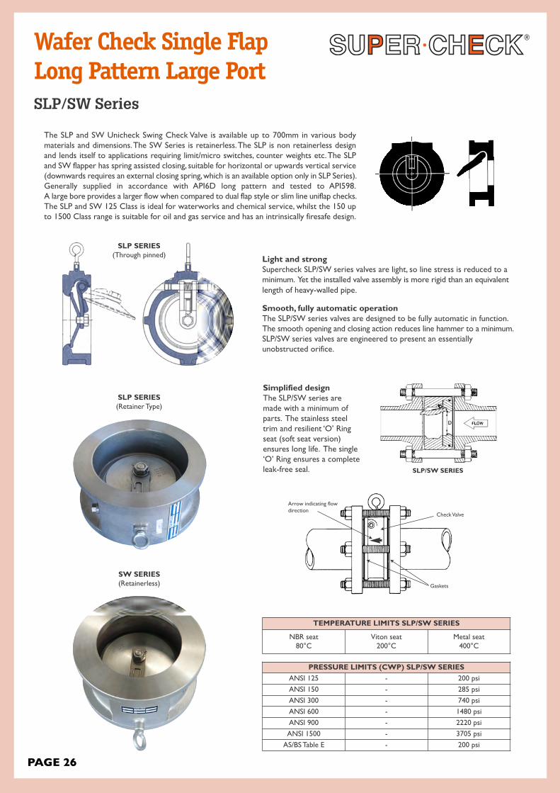
The SLP and SW Unicheck Swing Check Valve is available up to 700mm in various bodymaterials and dimensions. The SW Series is retainerless. The SLP is non retainerless designand lends itself to applications requiring limit/micro switches, counter weights etc. The SLPand SW flapper has spring assisted closing, suitable for horizontal or upwards vertical service(downwards requires an external closing spring, which is an available option only in SLP Series).Generally supplied in accordance with API6D long pattern and tested to API598.A large bore provides a larger flow when compared to dual flap style or slim line uniflap checks.The SLP and SW 125 Class is ideal for waterworks and chemical service, whilst the 150 upto 1500 Class range is suitable for oil and gas service and has an intrinsically firesafe design.
Check Valve
Gaskets
Arrow indicating flowdirection
Simplified designThe SLP/SW series aremade with a minimum ofparts. The stainless steeltrim and resilient ‘O’ Ringseat (soft seat version) ensures long life. The single‘O’ Ring ensures a completeleak-free seal.
SLP SERIES(Through pinned)
SLP/SW SERIES
Wafer Check Single FlapLong Pattern Large PortSLP/SW Series
PAGE 26
SW SERIES (Retainerless)
SLP SERIES(Retainer Type)
PRESSURE LIMITS (CWP) SLP/SW SERIESANSI 125 - 200 psi
ANSI 150 - 285 psi
ANSI 300 - 740 psi
ANSI 600 - 1480 psi
ANSI 900 - 2220 psi
ANSI 1500 - 3705 psi
AS/BS Table E - 200 psi
TEMPERATURE LIMITS SLP/SW SERIES
NBR seat80°C
Viton seat200°C
Metal seat400°C

PERFORMANCE STANDARD
• ANSI B16.5 [1.5” up to 24”] - Flange Dimension• API 6A - Face to Face Dimension• API 598 - Testing, allowable leakage rate• ANSI B16.34 - Wall Thickness
RETAINERLESS DESIGN
The SW Series unique design doesn’t have a shaft hole boredthrough the body wall, unlike many competitors. This uniquedesign prohibits any possibility of shell leakage and makes thevalve inherently fugitive emission by design.
DESIGN & PERFORMANCE STANDARD SERIES SW RETAINERLESS
SW COMPONENTS
SP01 Body
SP02 Disc
SP03 Insert
SP04 Hinge Pin
SP05 Spring
SP06 Washer
SP07 Set Screw
SW SERIES (Retainerless)
SW SERIES (Retainerless)
SW SERIES (Retainerless)
PAGE 27
SW Series

PAGE 28
WAFER SWING BODY DIMENSION FOR SLP/SW
DIMENSIONS* SLP/SW (150/300 CLASS*) BOLTING
Sizein (mm)
ANSI Rating
End Facing
A†(mm)
A1(mm)
B(mm)
C(mm)
Qty Dia(mm)
Length (mm)
Weight Kg
1.5 (40)150 RF 51 67 46 4 13 23⁄4 2.0
300 RF 51 73 46 4 19 31⁄2 2.2
2 (50)150 RF 60 44 104 57 4 16 152 2.3
300 RF 60 44 111 57 4 16 152 3.2
3 (80)150 RF 72 51 137 82 8 16 178 4.1
300 RF 72 51 149 82 8 19 207 5.9
4 (100)150 RF 72 57 175 110 8 16 178 8.6
300 RF 72 57 181 110 8 16 178 12.8
6 (150)150 RF 97 70 222 158 8 19 203 13
300 RF 97 70 250 158 12 19 245 16.2
8 (200)150 RF 125 73 279 180 8 19 248 23
300 RF 125 73 308 180 12 22 286 32.1
10 (250)150 RF 146 79 340 241 12 22 279 43
300 RF 146 79 362 241 16 25 324 24.3
12 (300)150 RF 181 86 410 314 12 22 311 71
300 RF 81 86 422 314 16 29 372 80.9
14 (350)150 RF 184 108 451 336 12 25 330 81.6
300 RF 222 222 486 336 20 29 419 102.7
16 (400)150 RF 191 108 514 390 16 25 343 104
300 RF 232 232 540 390 20 32 441 187.9
* Class 600 to 1500 available from 1” (25mm) to 16” (400mm) refer to drawing.† Face to face dimension A1 is API594, A1 is to ANSI/ASME
RESILIENT ‘O’ RING SEAT FEATURES SLP/SW
1. A truly dynamic seal, mechanically contained in a specially designed groove.
2. Unique in design and application.3. As pressure is applied to the valve disc,
the seal is compressed into the groove, ensuring a consistent and uniform seal.
4. The load on the seal is controlled reducing wear for longer life.
Metal seated is also available.
SLP/SW Series

PAGE 29
LARGE PORT SIZEInlet ports and disc have been shape optimized to achieve a fullyopen position at low flow rates. Therefore, the SLP/SW series operates exceptionally well in the flow rates typically found inpipeline containing control valves and lines with varying mediaflows. Compare the SLP/SW series to typical full-sized swing checkvalves. Due in part to their oversized, heavier discs, these valvesonly fully open at larger flow rates. When activated at a lowerflow rate, these valves lose true controllability and do not fullyopen. A partially open disc creates an obstruction that produces a higher pressure drop and fluttering of the disc valve -disturbing the flow and increasing the chance of waterhammer. SLP/SW Series will eliminate or reduce these problems.
HIGH FLOW CAPACITYThe SLP/SW Series valve inlet elliptical shape and optimumdiameter, plus its virtually unobstructed opening combine to pro-duce a substantially higher flow capacity (Cv) than other wafercheck valves.
REDUCED WATER HAMMERThe design of the SLP/SW Series will largely reduce or eliminatewater hammer by closing the valve at the right moment (beforereverse flow occurs).
SPECIAL APPLICATION ACCESSORIES
A0 Eternal Spring
A1 External Spring & Weight
A2 Limit Switch
A3 Backflush Lever and Eternal Spring
A4 External Position Indicator
A5 Backflush Lever
A6 Emergency Shut-off, Fusible Link
A7 Dual Balanced Weights
A8 External Weight
A9 External Compression Spring
B1 External Compression Spring and Weight
B2 External Spring, Weight, Hydraulic Damper
B3 External Compression Spring, Weight & Hydraulic Damper
- Other
SLP/SW PART NUMBER CODESLP - Conventional DesignSW - Retainerless Design
A- Class 150 G- BST-CB - Class 300 H- BST-DC- Class 400 I - BST-ED- Class 600 J - BST-FE - Class 900 K- BST-HF - Class 1500 L - ASA125
M -Other
1 - RF2 - Smooth3 - RTJ4 - Butt Weld
A- Carbon SteelB - 316 Stainless SteelC- 304 Stainless SteelD- Chrome Plated SteelE - Cast IronF - Ductile Iron
2 - Epoxy Coating internal/external3 - Galvanized and epoxy coated4 - ENP body5 - Standard body
B - Carbon SteelK- Stainless Steel 316L - Stainless Steel 304
1 - Integral Resilient2 - Integral Metal
A- Buna NB - VitonC- TeflonD- EPDME - Low Temp, Buna NF - Peroxide Cured Buna N
(90 Durometer)G- AtlasH- Metal Seat as BodyI - 316SS OverlayJ - Stellite Overlay
1 - Inconel2 - 316SS3 - 304SS
A- 316SSB - 304SS
T - TeflonS - 316SSN - NA
1 - Wafer2 - Lugged3 - Flanged
See Table
Model
Class
Ends
Body
Coating
Disc
Seat Type
Seat Insert
Spring
Hingepin
Washer
Body Type
Acc.
X X X X X X X X X X X X X
SLP/SW Series
valve Size Cv Min Flow to Fully
Open valveApprox PressureDrop w/Water
inch / mm GPM Ft/sec. PSI
1 / 25 30 28 10.4 0.78
1.5 / 40 38 68 10.7 2.1
2 / 50 84 46 4.4 1.7
2.5 / 65 137 76 5.1 1.4
3 / 75 221 197 8.5 1.1
4 / 100 373 157 4 1.4
5 / 125 679 352 5.6 1.1
6 / 150 931 367 4.1 1.5
8 / 200 1440 428 2.7 1.6
10 / 250 2623 837 3.4 1.1
12 / 300 3531 1229 3.5 1.2
14 / 350 3226 1180 2.7 2
16 / 400 3911 1447 2.5 2.6
18 / 450 5799 3376 4.8 1.7
20 / 500 7769 6500 6.3 1.5
24 / 600 10105 8321 5.9 1.6
28 / 700 14100 9250 5.3 1.5
30 / 750 18041 10303 5.1 0.9
32 / 800 20900 12150 5.0 1.4
36 / 900 25675 15850 5.2 2
40 / 1000 39340 25310 6.1 2.4
42 / 1050 47914 31304 7.5 2.7
48 / 1200 44983 33095 5.9 1.6
54 / 1350 63000 45000 6 .9
60 / 1500 70500 62800 6.2 1.1
Full open stable minimum velocity and the efficiency calculated at a normal velocity of 10 f/sec.
PRESSURE DROP WITH WATER

• 50NB thru 1000NB 150 Class to 900 Class• Drop-In or Thru-Pin Clappers• Material: Carbon Steel, Chrome Plate, Stainless, NI-Aluminium-Bronze, PTFE coated, Hastelloy, Titanium etc
• API6D Short Pattern, reduced bore (equal or better flow characteristics to a dual flap wafer check valve)
• Can be fitted with closing spring on request.• Spring can be fitted around shaft to reduce chattering• Super-Lite is lighter, smaller and therefore less expensive both to install and to maintain than conventional check valves.Because dual flap wafer checks are not only reduced bore but also have a central bar, superlite checks still have equalor better flow characteristics in most sizes.
• Simplified Design - There are only five parts in the Body of the Super-Lite.• Will close at very low pressure (closes under weight of disc alone)• O-rings housed in special profile grooves for high pressure with composition holes behind o-rings. Generally opens aslow as 2 kpa minimum differential.
NOTICEDo not install near rotating or
reciprocating device, not suitable towithstand “hammering”
OPTIONSFace Type:O-Ring face, smooth finish*, RTJ or spiral face.* Standard to 12", o-ring face over 12" (depending on class)
SealsViton, Teflon, peroxide cured Buna-N, EPDM etc.
TEMPERATURENBR: -40 to 90°C, FPM/Viton 150°C, PTFE -30° to 200°CMetal to Metal will do higher temp up to 350°C
SERvICESteam PTFE (only up to 200° C)Hot Water (Subject to temperature)Air, Oil, Water, NBR, Viton, Buna, PTFE Any
MATERIALS
* Nickle plated or galv on request.
FLOW COEFFICIENT:(Cv)
• The flow coefficient (Cv) is the flow of water in US gallons/min passing through a valve with a resulting pressure loss of 1 PSI
Body 316SS 304SS Steel Ni-AluminiumBronze
Seat & Body SealMetal to Metal, Viton, Teflon,EPDM or Buna
Metal to Metal,Viton, Teflon,EPDM or Buna
Metal to Metal, Viton, Teflon,EPDM or Buna
Metal to Metal,Viton, Teflon,EPDM or Buna
Flapper + Pin 316SS 304SS * Steel NI-AI-BZ
U-Bolt 316 304SS * Steel NI-AI-BZ
ND 50 (2) 65 (21⁄2) 80 (3) 100 (4) 125 (5) 150 (6) 200 (8)
Cv 42 73 107 329 646 747 1338
Wafer Check Super-LiteModel 2024
PAGE 30
A B
C

DIMENSIONS
WORKING PRESSURECLASS 125/BST-D/BST-E/PN10
To 300NB:- 200 PSI CWP (oil, water etc.)350 to 600NB:- 100 PSI CWP (oil, water etc.)Available to suit -40°C to 200°C. (Pressure rating dropsfor higher temperature applications) Over 200°C on request.
WORKING PRESSURECLASS 150/300
ANSI 150:- 280 PSI CWPANSI 300:- 720 PSI CWPANSI 600 and ANSI 900 available up to 450NBAvailable to suit -40°C to 200°C. (Pressure rating dropfor higher temperature applications) Over 200°C onrequest.
FLANGE FACINGSO-RINGO-Ring in conjunction with serrated face.Designed so that either type will provideeffective sealing surface. Only required inlarger sizes.
RTJ (Ring Joint)
RF/FF/SF
STAINLESS STEEL AISI 316 FULLY PTFE COATED
RUBBER FLAPPER OPTION
A rubber flapper can be supplied, whichalso acts as a body gasket. This design islight weight, cheaper to make easy &cheap to change clapper, low wearingand maintenance free. Can be suppliedin Buna, EPDM etc. The same dimen-sions and bore sizes etc. apply, suits low
pressure applications.
PART LIST1. Body2. Clapet + Pin3. Eyebolt4. Body O-Ring*5. Seat O-Rings6. Screws7. Washer* Optional smaller sizes
vALvE DATA
ØB
ØC
NB(mm)
NB(“)
150#øA
150#øB
300#øA
300#øB
600#øA
600#øB
Min. PortI.D.
150#/300#øC
Min PortI.D. 600#
øCøE
50 2 104 14/19 111 14/19 14/19 14/19 27 27 52.7
65 2.5 124 14/19 130 14/19 14/19 14/19 38 65.9
80 3 136 14/19 149 14/19 14/19 14/19 48 48 78.1
100 4 174 19 188 19 19 19 69 67 102.3
125 5 197 19 216 19 19 19 100 126.6
150 6 222 19 251 20/22 20/22 20/22 110 105 151.0
200 8 279 22/29 308 27/29 27/29 27/29 140 127 199.9
250 10 340 26/29 362 33/38 33/38 33/38 191 178 254
300 12 410 32/38 422 41/51 41/51 41/51 203/240 216 305
350 14 410 38 485 46 46 46 270
400 16 514 44 540 52 52 52 310
450 18 549 50 597 57 57 57 360
500 20 606 56 654 68 68 68 405
600 24 716 68 485
700 28 832 80
800 32 940 86
900 36 1048 96
1000 40 1162
Size in mm KvMin. openingpressure in br(vertical)
Zeta Value
50 49 0.00650 4.09
65 76 0.00700 4.98
80 125 0.00650 4.12
100 183 0.00800 4.00
125 340 0.00750 3.32
150 500 0.00950 3.18
200 1100 0.00875 2.08
250 1610 0.01100 2.37
300 2290 0.01300 2.43
350 3880 0.01550 2.82
400 2700 0.01700 2.94
450 5310 0.02000 2.28
500 6550 0.02350 2.29
600 9500 0.02300 2.25
PAGE 31
Model 2024
B
ØA
ØE
ØC
1
4
3
12
5

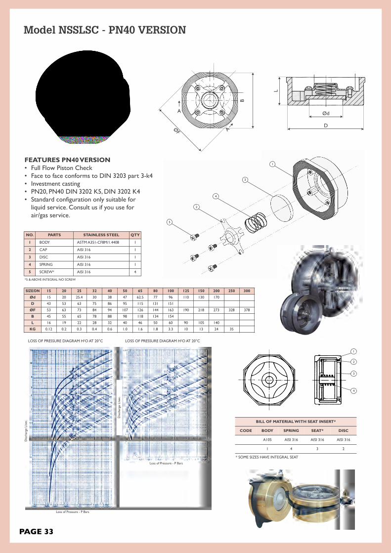
Check Valve Non Slam Axial Disc Full Flow Piston CheckModel NSSLSC
SC01, DN 15-100 mm (1⁄2”-4”) withspecial centering ring (optional)
SC02, DN 15-100 mm (1⁄2”-4”) with self-centering body
DEGREE OF OPENING
stillclosed
slightly opencheck valvewill clatter
more widelyopen
clatter stillpossible
fully openno
clatter
Degree of opening of a spring-assisted non-return valves as a function of volume flow
PARTS MATERIALS
DIMENSIONS AND WEIGHT
SC03, DN 125-200 mm (5”-12”)(Stem guided piston check)
BODY WCB ZG1Cr18Ni9Ti SS304 SS304L ZG1Cr18Ni
12M02TiSS316(1.4408) SS316L
DISC & SEAT 2Cr13ZG1Cr18Ni
9TiSS304 SS304L
ZG1Cr18Ni12M02Ti
SS316 SS316L
SPRING 4Cr131Cr18Ni9Ti
-L0Cr18Ni9-L
00Cr19Ni11-L
1Cr18Ni12M02Ti-L
0Cr17Nil2M02-L
00Cr17Nil4Mo2-L
SHAFT 2Cr131Cr18Ni9Ti
-L0Cr19Ni11 (304)
00Cr19Ni11(304L)
1Cr18Ni12Mo2T1
0Cr17Ni12M02(316)
00Cr17Ni14M02 (316L)
TEMP.* -29°C ˜300°C* - 196°C ˜300°C*
Required cracking pressure Mbar
CLASS 150* 300* 600 900 PN40SIZE DIMENSIONS (MM) WEIGHT
(KG)DIMENSIONS (MM) WEIGHT
(KG)DIMENSIONS (MM) WEIGHT
(KG)DIMENSIONS (MM) WEIGHT
(KG)DIMENSIONS (MM) WEIGHT
(KG)IN MM THICKNESS OD THICKNESS OD THICKNESS OD THICKNESS OD THICKNESS B F1⁄2 15 16 47 0.2 25 53 0.23 25 53 0.25 25 63 0.3 16 45 53 0.13⁄4 20 19 57 0.3 31.5 65 0.36 31.5 65 0.38 31.5 69 0.4 19 55 63 0.2
1 25 22 66 0.45 35.5 72 0.52 35.5 72 0.55 35.5 78 0.6 22 65 73 0.3
11⁄4 32 28 75 0.6 40 81 0.75 40 81 0.8 40 88 1 28 78 84 0.4
11⁄2 40 31.5 85 0.8 45 95 1.1 45 95 1.2 45 98 1.5 32 89 94 0.6
2 50 40 103 1.2 56 110 1.95 56 110 2 56 142 2.5 40 98 107 1.0
21⁄2 65 46 122 1.9 63 129 2.9 63 129 3 63 164 4 46 118 126 1.6
3 80 50 136 2 71 148 5.5 71 148 6 71 167 8 50 134 144 1.8
4 100 60 175 4 80 180 9 80 192 10 80 205 13 60 154 163 3.3
5 125 90 196 10 110 215 15 110 240 17 110 247 20 90 190 10
6 150 106 222 13 125 250 20 125 265 22 125 288 25 105 218 13
8 200 140 279 24 140 185 273 24
10 250 150 340 35 150 266 35
12 300 160 410 50 160 410 50
PTFE & PP BODY ALSO AVAILABLE* Absolute maximum range at 0 PSI and dependent upon materials and trim. Up to 400°C possible depending on spring.However, severe pressure limitations apply as temperature increases (400°C limit is zero PSI)
*PN40 will multi fit ANSI 150 & ANSI 300
F
B
PAGE 32
LOSS OF PRESSURE DIAGRAM H2O AT 20°C LOSS OF PRESSURE DIAGRAM H2O AT 20°C
BILL OF MATERIAL WITH SEAT INSERT*
CODE BODY SPRING SEAT* DISC
A105 AISI 316 AISI 316 AISI 316
1 4 3 2
* SOME SIZES HAVE INTEGRAL SEAT
Loss of Pressure - P Bars
Loss of Pressure - P Bars
FEATURES PN40 vERSION• Full Flow Piston Check• Face to face conforms to DIN 3203 part 3-k4• Investment casting• PN20, PN40 DIN 3202 K5, DIN 3202 K4• Standard configuration only suitable forliquid service. Consult us if you use for air/gas service.
Discharge L/sec.
Discharge L/sec.
PAGE 33
NO. PARTS STAINLESS STEEL QTY
1 BODY ASTM A351-CF8M/1.4408 1
2 CAP AISI 316 1
3 DISC AISI 316 1
4 SPRING AISI 316 1
5 SCREW* AISI 316 4
*5 & ABOVE INTEGRAL NO SCREW
SIZE/DN 15 20 25 32 40 50 65 80 100 125 150 200 250 300
Ød 15 20 25.4 30 38 47 62.5 77 96 110 130 170
D 43 53 63 75 86 95 115 131 151
ØF 53 63 73 84 94 107 126 144 163 190 218 273 328 378
B 45 55 65 78 88 98 118 134 154
L 16 19 22 28 32 40 46 50 60 90 105 140
KG 0.12 0.2 0.3 0.4 0.6 1.0 1.6 1.8 3.3 10 13 24 35
Model NSSLSC - PN40 VERSION
1
2
3
4
5
2
4
3
1
Ød
D
L
B
ØF
A
A

The Supercheck R-APSC-V is our versatile, low maintenance, ‘non slam’, spring assisted, problem solving check valve. This threadedinline check valve is mountable vertically or horizontally and preventswater hammer and flow reversal. Fit it and forget it! The 316 SS body, body-guided disc and seat ensure corrosion resistance for mostmediums and lapped seats & disc provides tight shut-off.
• Sizes from 1/2” to 3”• NPT, SW or BW ends.
• CONDENSATE• WATER• STEAM• CHEMICALS• NITROGEN• WATER INJECTION
• BOILER FEED• FLARE LINES• AMMONIA• CRYOGENIC• OXYGEN COOL DOWN
OPTIONS
• Hastelloy C• Alloy 20• SEVERE Chemical Service• Soft seat for bubble tight shut off• NACE• Higher cracking pressures
APPLICATIONS
COMPONENT 750 PSI CWP 3600 PSI CWP
Body A351 CF8M A351 CF8M
Seat (3,4) A351 CF8M A351 CF8M
Disc A240 316 A240 316
Spring Inconel® X-750 or 316 Inconel® X-750 or 316
Body Seal (4) Zelon (243°C max.) or Buna-N Zelon (204°C max.) or Buna-N
Option: Body seal weld (371°C max.) Option: Body seal weld (371°C max.)
Threaded In-Line Check Valve750 to 3000PSIModel R-APSC-V
3 Optional Buna-N or Zelon soft seats for bubble tight shut off.4 Only Zelon is suitable for steam. Buna-N is required for CO2 resistance / NACE service.
PAGE 34
SEAT
“O” RING
BODY
DISC
SPRING

NOTES:
(1.) Cracking pressure (PSIG)(2.) Maximum Temperature for Buna-N(3.) ASME B16.34-2004(4.) Maximum temperature for Viton®
and Zelon w/3600 PSI CWP, R-APSC-V.(5.) Maximum temperature for Zelon
w/750 PSI CWP, R-APSC-V.
PRESSURE TEMPERATURE RATING (PSIG) (3)
Temperature A351 CF8M Alloy 20 (CN7M) Hastelloy C(CW-12MW)
(C°) 750 CWP 3600 CWP ASME 300 ASME 300
38 750 3600 600 600
93 645 3095 520 550
121 (2) 610 2945 490 535
149 580 2795 465 520
204 (4) 535 2570 420 490
243 (5) 510
Class 750 CWP / 500 PSI CWP
3600 PSICWP
1/2”(15NB)
A (mm) 68 80
B (mm) 41 48
Weight (Kg) 0.49 0.68
Cv 7 6
CP(1) 0.29 0.62
3/4”(20NB)
A (mm) 76.2 76
B (mm) 54 59
Weight (Kg) 0.68 1.36
Cv 13 11
CP(1) 0.24 0.26
1”(25NB)
A (mm) 84.3 95
B (mm) 64.5 70
Weight (Kg) 0.86 2.04
Cv 22 19
CP(1) 0.36 0.36
1 1/4”(32NB)
A (mm) 98.3
B (mm) 77.7
Weight (Kg) 1.76
Cv 39
CP(1) 0.28
1 1/2”(40NB)
A (mm) 120.6
B (mm) 87.3
Weight (Kg) 2.13
Cv 54
CP(1) 0.24
2”(50NB)
A (mm) 127 162
B (mm) 111.7 109
Weight (Kg) 3.49 6.35
Cv 93 65
CP(1) 0.42 0.36
3”(80NB)
A (mm) 171.4
B (mm) 157.2
Weight (Kg) 8.52
Cv 180
CP(1) 0.20
A
B
SEAT SPRINGD-RING DISC
BODY
PAGE 35
FLOW
Model R-APSC-V

DESIGN FEATURES• Design to API 6D and Face to Face Distance as per manufacturer’s standards.• Fast acting spring prevents water hammer and pressure surge, this is a truly Non Slam Check Valve.• Short Travel and Ultra Light weight Disc make the advantages of Non Slam Check Valves possible and reduceswater hammering. Quick closing and fast traveling disc are the fundamental design features.
• High Velocity and Gas Flow under compressed conditions can reach sonic velocity and the ‘sonic booms’ aredetrimental to the valves operation. The simple but precisely calculated spring design overcomes this problem.
• Bernoulli’s equation of conservation of energy is the solution for spring design. Velocity head exchanges the energy with Pressure Head and the Supercheck Non Slam Check keeps on performing without the fear ofsonic boom and valves offer low Pressure Drop when compared to Dual Plate Check Valves staticpressure. Dropping the velocity head at vena contracta increases static pressure reducing cavitation.
• Single piece body construction allows High Pressure Applications and Non Slam Nozzle Check Valvesare inherently Fire Safe.
PRODUCT RANGE• Rating : ANSI #150, #300, #600, #900, #1500 & #2500 & up to 10,000 psi.• Material : ASTM A105, A182, Gr. LF2, Gr. F316, Gr. F51, Gr. F55 etc.• Designed using Computational Fluid Dynamics (CFD)• Low head loss & minimum pressure loss can be acheived.• Metal to Metal seated design.• Conical seating surface is self aligning & provides tight shut off.• Spring loaded disc design allows mounting in any orientation.
Non Slam Nozzle Check Valve
APPLICATIONS• Chemical, Oil & Gas Industries• Residual Heat Removal Systems• Nuclear Power Plants• Offshore & Onshore Production Platform, FPSO• Containment Isolation• Water, Steam, Gas, Vacuum• Steam Injection Systems• Power Station, Water Pumping Stations• Natural Gas, Refineries• Critical Equipment Discharge• Gas Compressor Unit• Cracker Plants
1 Body2 Diffuser3 Disc4 Seat5 Spring
CHARACTERISTICS• Non Slam Closure• Extremely quick Closure• Low Pressure Loss• Short stroke of disc• Axial movement of disc• Disc’s minimal wear characteristics
NOZZLE CHECK VALVE FLANGED ENDFLOW
NOZZLE CHECK VALVE HUB ENDFLOW
SW-NC/FL-NCFO Series
INSTALLATION
PAGE 36
1
2
3
4
5
FL-NCFO Series

Swing-Check
SupercheckDual DiscCheck Valve
Nozzle Check
StandardDual Disc Check Valve
Vr R
ever
se V
elocit
y
dr/dt Deceleration
Example Only. Refer to as built drawings. (FL-NCFO Series) also refer to drawings as all dimensions are different.
PAGE 37
SW-NCA & NCB Series
A/A1
OPEN SW-NCA Series
A/A1
CLOSED SW-NCB Series
250NB (10”) and above 150~2500LBS multi springloaded design (Model Number: SW-NCB) minimumpressure loss with excellent dynamic performance.
2
1
6 4
Multi Spring Loaded Nozzle Check valveSW-NCB Series
FaceToFace
Up to 250NB (10”) and 150~300LBS single springloaded design (Model Number: SW-NCA) minimumpressure loss with excellent dynamic performance.
3
4 5
Single Spring Loaded Nozzle Check valveSW-NCA Series
FaceToFace

Sizein 2 4 6 8 10 12 14 16 18 20 24 28 30 36
mm 50 100 150 200 250 300 350 400 450 500 600 700 750 900
ShortPattern
A
in 4.49 8.98 13.07 15.12 16.81 17.32 18.70 19.69 22.24 27.17 30.24 35.43 36.54 40.67
mm 114 228 332 394 427 440 475 500 565 690 768 900 928 1033
kg 6 21 38 118 198 254 312 373 484 965 1179 1404 1768 2344
LongPattern
A1
in 7.99 11.50 14.02 19.49 24.49 27.52 30.98 34.02 38.50 38.50 50.98 57/01 60.00 77.01
mm 203 292 358 495 622 699 787 864 978 978 1295 1448 1524 1956
kg 11 43 68 175 219 257 385 440 733 1037 1297 1805 2211 2443
Sizein 2 4 6 8 10 12 14 16 18 20 24 28 30 36
mm 50 100 150 200 250 300 350 400 450 500 600 700 750 900
ShortPattern
A
in 4.69 9.33 13.58 15.12 17.32 17.48 19.05 19.69 22.24 27.17 30.24 35.43 36.54 40.67
mm 119 237 345 394 440 444 484 500 565 690 768 900 928 1033
kg 8 36 68 147 226 274 400 477 621 981 1233 1980 2155 3303
LongPattern
A1
in 10.51 14.02 17.52 20.98 24.49 27.99 32.99 39.02 42.99 47.01 55.00 62.99 65.00 82.01
mm 267 356 445 553 622 711 838 991 1092 1194 1397 1600 1651 2083
kg 12 43 86 184 251 298 534 582 738 1056 1363 2148 2380 3922
ANSI 150
ANSI 300
Example Only. Refer to as built drawings. (FL-NCFO Series) also refer to drawings as all dimensions are different.
ANSI INSTALLATION DIMENSIONSDimension for larger valve sizes available upon request.Also available with JIS, DIN, BN, AS and ISO dimensions.API 2000, 3000, 5000, 10000 also available
SW-NCA Single Spring SW-NCB Multi Spring
SW-NCA Single Spring SW-NCB Multi Spring
FACE TO FACE DIMENSIONS
PAGE 38
Supercheck Nozzle Check valve is designed to meet the criteria of conventional check valves by allowing forwardflow under normal conditions, opening easily and firmlybackseating at low velocity.
SW-NCA & NCB Series Dimensions
A/A1 A/A1

Sizein 2 4 6 8 10 12 14 16 18 20 24 28 30 36
mm 50 100 150 200 250 300 350 400 450 500 600 700 750 900
ShortPattern
A
in 7.99 9.61 13.98 16.02 17.99 18.03 19.61 20.59 27.09 28.27 30.63 34.33 38.19 45.98
mm 203 244 355 407 457 458 498 523 688 718 778 872 970 1168
kg 12 41 152 176 302 383 484 711 1219 1242 1741 2394 2700 4050
LongPattern
A1
in 11.50 17.01 22.01 25.98 30.98 32.99 35.00 39.02 42.99 47.01 55.00 52.99 65.00 82.01
mm 292 432 559 660 787 838 889 991 1092 1194 1397 1600 1651 2083
kg 28 67 174 225 365 464 587 861 1192 1383 2170 2748 3541 7901
Sizein 2 4 6 8 10 12 14 16 18 20 24 28 30 36
mm 50 100 150 200 250 300 350 400 450 500 600 700 750 900
ShortPattern
A
in 8.19 9.84 14.33 16.42 18.43 18.62 20.08 21.10 27.76 28.98 31.38 35.20 39.13 47.13
mm 208 250 364 417 468 473 510 536 705 736 797 894 994 1197
kg 27 54 174 261 435 607 625 1098 1296 1908 2864 4185 4275 6525
LongPattern
A1
in 14.49 17.99 24.02 29.02 32.99 37.99 40.51 44.49 47.99 52.01 60.98
mm 368 457 610 737 838 965 1029 1130 1219 1321 1539
kg 41 136 229 301 616 796 1195 1317 1819 2647 3317
ANSI 600
ANSI 900
SW-NCA Single Spring SW-NCB Multi Spring
SW-NCA Single Spring SW-NCB Multi Spring
ANSI INSTALLATION DIMENSIONSDimension for larger valve sizes available upon request.Also available with JIS, DIN, BN, AS and ISO dimensions.API 2000, 3000, 5000, 10000 also available
PAGE 39
Supercheck Nozzle Check valve is designed to beclosed prior to reverse flow as non-slamming with aspring loaded disc that allows mounting in any orientation.
SW-NCA & NCB Series Dimensions
A/A1 A/A1
FACE TO FACE DIMENSIONS
Example Only. Refer to as built drawings. (FL-NCFO Series) also refer to drawings as all dimensions are different.

Notes

Notes

Notes

View our catalogues at www.australianpipelinevalve.com.au
AUSTRALIAN PIPELINE VALVE BRAND RANGE - CATALOGUES
APV FAMILY OF BRANDS RANGE - CATALOGUES
COMPLETE PRODUCT LINE
“Australian Pipeline Valve
produces isolation,
control and flow reversal
protection products for
severe and critical service
media in utility, steam,
pipelines, oil & gas
and process industries.
APV valves and pipeline
products form the most
competitive portfolio
in the market.”
Gate, Globe & Check Valves - Forged Steel
Oilfield Products Valves & Wellheads
Plug Valves Lubricated, Sleeved & Lined
Gate, Globe & Check Valves - Cast
Diamond Gear Gearboxes
Flowturn Gate, Globe & Check Valves
Flowturn Instrument Valves
Flowturn Ball Valves Multiway & Deadman
Flowturn Strainers & Sight Glasses
Supercheck Wafer Check Valves
Superseal Butterfly Valves
Steamco Steam Valves
Superseal Industrial Ball Valves
TwinLok Tube Fittings Uniflo Check ValvesTorqturn Actuators
Ball Valves Floating & Trunnion Mounted
Ball Valves Floating Small Bore
Ball ValvesSpecial Service
Product Brochure
Contact us for your local stockist/distributor

Quality assurance and certificationWe are continually improving all facets of quality assurance. Full metallurgical and test certificates are always supplied for all pressure retaining parts, we also provide it on all major trim components.
We have endeavoured to provide a broad outline of our range and capabilities. Because we are continually developing new products for our customers this catalogue will, to some extent be incomplete. This catalogue is a general overview only, individual drawings and data sheets can be furnished on request.
If you have any requirement in the field of valves, please contact us for a prompt response. Continuous development of Australian Pipeline Valve products may necessitate changes in the design or manufacturing processes. Australian Pipeline Valve reserves the right to effect any such changes without prior notice.
www.australianpipelinevalve.com.au
© Australian Pipeline Valve 1990 - 2013 Edition
LocaL Distributor
a D E L a i D E • b r i s b a N E • P E r t H