check valves as safeguards: friend or foe in process...
TRANSCRIPT
Check Valves as Safeguards: Friend or Foe in Process Hazard Analysis
Author: Kay A. Modi, Senior Process Safety Consultant with JCL Risk Services
Presented April 25, 2017
SynGas Association
Producers & Suppliers of the Synthetic Gas Industry
1 Abstract The use of check valves as a Process Hazard Analysis safeguard is ardently debated, and corporate policies are not consistent. The proper design and use of check valves in processes are prescribed by codes, recommended practices, and historical design practices. Their reliability, as well as their usefulness in reducing hazards, depends on many factors. Their use as safeguards is explored in PHAs as well as more refined analyses such as Layers of Protection Analyses, Event Trees, and Incident Investigations. Concerns presented are the leakage rates of closed check valves (non-return valves), potential problems during stagnant flow periods, potential flaws in design intent, double jeopardy of unrevealed failures, and application in gas and liquid services. Their use as safeguards should incorporate a discussion of their ability to reliably prevent the hazard. Risk, mitigation, consequence, and other principles will be used to frame the check valve discussion and its varied acceptance as a safeguard and qualitative credit value.
Preventing major consequences may have lesser secondary consequences, but are still a concern for personnel injury from releases. While check valves impede backflow, well-engineered non-return valves may be able to reduce flow in a reverse direction with limited to no consequence.
2 Review of Check Valves in Processes: Check valves are required by codes and recommended practices in many engineering documents, so facilities have a number of check valves in primary sections of the process. However, the codes and practices seldom note what type of check valve to install. Check valves are recommended to prevent or minimize back flow in:
• Pump discharges to prevent reverse rotation and internal pump damage; • Compressor discharges; • Truck/Railcar unloading;

Check Valves as Safeguards
Page 2 of 12
• Utility hose connections to process lines; • Truck or railcar vapor balance lines for one direction flow; • Vessel drain lines to environmental systems; • Interconnecting transfer lines between tanks; • Fired-heater process discharge piping (to prevent flow if tubes rupture); • Reflux lines into towers or distillation columns to protection the pump from reverse rotation; • Connections to flare lines; • Reactor systems with multiple feeds to prevent contamination of each feed; • Permanent steam injections into processes; and • Reboiler gas flows back to the column.
3 Preventative Safeguards
The preventative safeguard definition is to forestall the occurrence of a particular loss event, given that an initiating cause has occurred (Guidelines for Hazard Evaluation Procedures, Glossary xxvi).
Considering a series of check valves or even a single check valve as a safeguard prior to the “development of its functional test and required frequency” during a PHA study is better as a recommendation. It is better to prove the premise that a specific safeguard can be well-maintained. An example of a “preventative safeguard failure probabilities” lists check valves as once per year for hardware automatic safety system that is not functionally tested [1.0 failures per year compared to process control valves with a failure rate of 0.1 per year], such as a typical single check valve (CCPS Guidelines for Hazard Evaluation Procedures, Reference 1, page 221). Although this reference is copyrighted in 2008, it highlights a repeated concern. What is an appropriate functional test and what frequency is needed? What are the probabilities of failure? According to check valve manufacturers, each type and service has its own characteristics.
4 Check Valve Probability of Failure Approach
There are numerous key issues to be assessed in the placement and selection of check valves within the process and impacts on process and non-routine operating conditions. These issues may include:
• Understanding what happens when process systems are partially shut down or inactive and the potential for backflows need review (unusual pressure profiles of gases and liquids when processes do not have greater than 100 psi differentials);
• Event Tree analysis presents the multiple consequences of check valve failures; • Double jeopardy is probable for unrevealed failures of safeguards (not a true double failure when in
failed state);

Check Valves as Safeguards
Page 3 of 12
• Quantification of backflow rate by check valve type and size and age is typically not known or tested by manufacturing companies (unless engineer tested for a specific design);
• Industrial guidelines suggest an assumption for 10% backflow if there are dual check valves that are well maintained;
• Maximum allowable leakage rate (is it acute exposure within 10 or 100 feet of the leak point if preventing flows directly to the environment?) that is tolerable for a release and what is the exposure prevention objective;
• Check valves placed in the piping system that is used to vent overpressure can fail closed and not permit flow; and
• Notations from distributors indicate that zero leakage of metal-to-metal check valves cannot be readily achieved without an elastomeric element in the seating arrangement. Thus, if the check valve has metal to metal seating, leakage should be expected and included in the consequence assessment in PHAs.
4.1 Integrity and Latent Failure The ability to verify check valve functionality raises an important question. How dependable are they when used in industrial facilities? Probability of failure may include the review of several issues.
• Integrity depends on use (number of demands to close per year), service (clean, well know contaminants), and maintenance (reliability, testing while in-service, frequency of complete functional testing).
• Latent failures include contributory factors that may lie dormant for days, weeks, months, or years until they contribute to an incident. Check valves rarely have revealed failures, except when impeding the normal flow direction due to failure to open (stuck in the closed or partially closed position).
• If the frequency of check valve closure per year (demand) is once per year, the check valve may have a reliability of 0.1 failures per year for a well-maintained single check valve that is relatively new construction (limited studies to support this assumption). Refer to Guidelines for Initiating Events and Independent Protection Layers of Protection Analysis (Reference 2) for more information.
• The ability to perform maintenance at a frequency required by demand is critical. Demand of once per year or once per day have very different requirements to validate performance.
• The ability to test check valves while in service and evaluate the ability to reduce latent failures (is the testing effectively reducing failures) is important for any process control element.
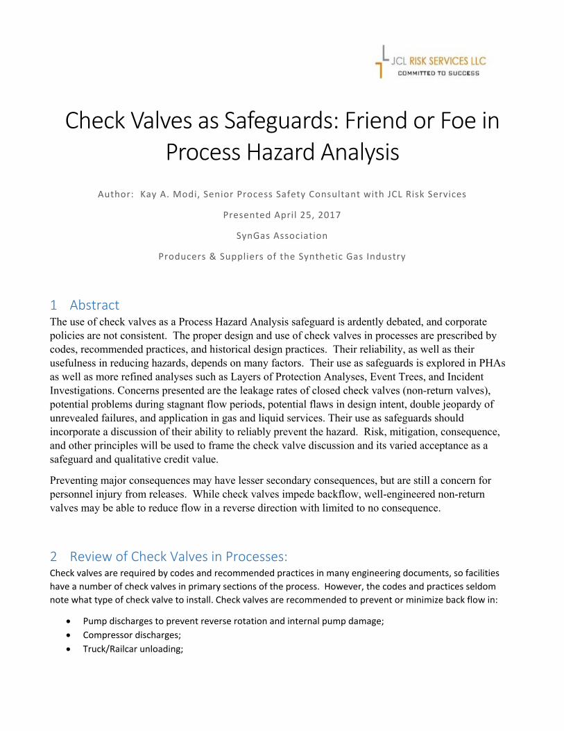
Refer to the following study by Department of Energy (DOE) on check valves in the nuclear industry and their graph on tracked cause of failures. It is easily noted that the failure of stuck open is a significant percentage of the failure mode.
Check Valves as Safeguards
Page 4 of 12
Figure 4.1, Distribution of Significant Failures by Check Valves
(Oak Ridge National Laboratory, Reference 3)
Double Jeopardy is typically not addressed in PHAs based on the assumption that two revealed failures (such as a control valve failure at the same time as a utility supply failure) occur concurrently will have very low frequency of the cause of events. By contrast, unrevealed failures will and can occur at any time prior to the revealed failure initiating event, and the probability of the component is in the failed state when an initiating event occurs will generally be much greater frequency than [revealed failure components]. For this reason, when an initiating event is combined with one or more unrevealed failures, this is “not double jeopardy.” (Guidelines for Initiating Events and Independent Protection Layers of Protection Analysis, Reference 2).
Recommended maintenance needs to be based on the service, which includes the number of closures and service (clean or dirty streams). Services that cycle open-closed need frequent maintenance compared to those that typically remain open during normal operations (always forward flow). As an example, flows may vary based on the alternating selection of piping systems for routing product ammonia to storage tanks (or flows that are intermittent). These check valves are cycling on and off and need more frequent maintenance programs to maintain integrity.
5 Unrevealed Failures of Check Valves Due to Lack of Functional Testing
An unrevealed or latent failure (sometimes termed an unannounced failure) does not have an immediate effect on the system or surroundings, so it can persist in the failed state for an extended duration (often months or years) before being detected and corrected or before being needed to perform its intended function and not doing so. Examples of unrevealed failures include an emergency

Check Valves as Safeguards
Page 5 of 12
block valve being stuck in the open position or check valve being stuck in the open position which is unrevealed due to normal forward flow. This highlights the importance of periodically performing functional tests of standby safety systems (API Standard 521, Reference 4).
API Standard 521 also discussed latent failures of check valves as a probable event for pressure safety valve (PSV) design.
Reverse flow through a pipe can be initiated by turning off a pump or compressor without closure of an isolation valve. This is characteristic of an unloading operation or alternating feeds into several pressurized storage tanks. High frequency of starts and stops and valve closures associated with the unloading of hazardous materials disqualify any working knowledge of the check valve’s ability to function based on high demand mode of operations. A high frequency of maintenance and testing would be appropriate for this service.
Industrial operators recognize the importance of not back-flowing through process lines. However, are operating managers and engineers training new operators to understand the importance of proper maintenance of check valves? Additionally, do the operators understand the intent and limitation of the design? If an operating unit properly maintains a few due to severe service, is it apparent which check valves are not maintained?
6 Historical Perspective of Design and Operation of Facilities and Approach for Consequences
Historically, the inclusion of check valves in process designs was primarily for protection of reverse flow on assets (e.g., preventing reverse rotation, contaminating utilities). Many systems were built decades ago and did not list check valves as equipment. Thus, maintenance was not specified by designers. Many facilities had check valves that were unnumbered and untracked assets in operating plants from the design, construction, and operating standpoint (may be the current status for a facility). Thus, they traditionally have not had tracked maintenance for integrity. The service and predicted maintenance intervals may be unknown without the track record of the performance.
Check valves can be engineered for a specific purpose or many that can be bought off the shelf. Most quality check valves have a stem and spring loaded plate to assist in shut off. Tight seals require a different type of material (typically soft seated materials for tight shutoff).
Hazards of service should be taken into consideration. Propane, butanes, liquified petroleum gas (LPG), anhydrous ammonia, and other services (possibly highly hazardous toxic/reactive materials) may require additional consideration to allow for the consequences of failure. Less hazardous materials may simply have lower consequences when flow is reversed.
Reliability based on application should be reviewed. Unloading of raw materials into a pressurized vessel can be the most hazardous application of a check valve as a safeguard if the check valve is not “engineered for the

Check Valves as Safeguards
Page 6 of 12
service” and well maintained. The cycle of open-close is high and untested closure and untested performance during an operating period (between turnarounds) can lead to false dependence on its safeguarding the process when other safeguard’s failures coincide (probability of failure on demand). Unrevealed failures lead to misplaced confidence in safeguards. When was the last time a check valve was tested? How does an operating facility know if the current check valve is viable?
6.1 Estimating reverse flow through two check valves in series Notations from distributors indicate that zero leakage of metal-to-metal check valves cannot be readily achieved without an elastomeric element in the seating arrangement. Thus, if a check valve has metal to metal seating, leakage should be expected and included in the consequence assessment in PHAs. The following from API Standard 521 provides a basis for estimation of back flow if it is unknown.
Experience has shown when inspected and maintained to ensure reliability and capability to limit reverse flow, two back-flow-prevention devices in series are sufficient to eliminate significant reverse flow. As the differential pressure increases, the use of additional safeguards should be considered to reduce the risk of check-valve latent failures resulting in mechanical equipment damage causing loss of containment. If reliability of the series of back-flow prevention cannot be assured, then it can be necessary to estimate the reverse flow. The quantity of back-flow leakage through check valves in series depends on the types of check valves, the fouling nature of the fluid and other system considerations. Therefore, it is the responsibility of the user to determine an appropriate technique for estimating the reverse flow through the check valves in series. Where no specific experience or company guidelines exist, one may estimate the reverse flow through series check valves as the flow through a single orifice with an equal diameter equal to one-tenth of the largest check valve’s nominal flow diameter (API Standard 521, Section 4.3.4.4).
6.2 Assessing Consequences in PHAs with Two Levels PHAs can be performed to present the complexity of consequences when check valves are used as safeguards. Foremost, it is important to give check valves credit for reducing catastrophic releases of entire storage vessels at high flow rates, assuming proper design and maintenance. Second, it is important to evaluate the secondary consequence of reduced flow rates when check valves are used as a safeguard. The PHA needs to assess what additional safeguards are needed to prevent the secondary scenario (risk appropriate).
Refer to Appendix A for an assessment of both consequences, total failure of the check valve and success of the check valve closure with small release (leakage rate is smaller than forward flow).
6.3 What Does Good Look Like What does good look like for check valve applications? Refer to Appendix B for an example of a well-designed and well-maintained dual check valve system. The check valves can be serviced during operating periods. Appendix B also presents a review of a probable scenario (pump fails to operate) and its resolution through the

Check Valves as Safeguards
Page 7 of 12
use of Layers of Protection Analysis (LOPA). It reviews the consequences with the check valves’ success and failure to impede backflow.
6.4 Review of Consequences by Event Tree A review of possible consequences can be illustrated by an event tree for a reverse flow scenario associated with loading of hazardous materials (ammonia). There are multiple outcomes and varying probabilities. The following table compares the outcomes with check valve system design and reliability as the only variable (its probability of failure on demand (PFD)). It has three options; two check valves in series with an engineering design for purpose (tight shutoff with soft-seated construction), single check valve without a maintenance program, and double check valves and maintenance program (with 10% expected back flow).
In summary, the system that is not well maintained and has a single check valve has 455 times the frequency of catastrophic events than a well-designed tight-shutoff series of dual check valves (including an appropriate integrity program). This is based on the assumption that all other safeguards are equal (Quick Disconnect on hose, ESD shutoff of pump and isolation valve at a remote location). The outcome comparisons are presented below. The Event Tree for each case is presented in Appendix C for a detailed review.
Table 5.1, Comparing Failure Probability Between Check Valves that Fail at a High Rate versus New Check Valves (Dual System) that Are Well-Maintained
CASE 1:
50% FAILURE RATE OF SINGLE CV (10% LEAKAGE)
CASE 2:
10% FAILURE RATE OF SINGLE CV (WELL MAINTAINED), AND LEAKS AT 10% RATE
CASE 3:
10 % FAILURE RATE BUT WELL -DESIGNED FOR SHUTOFF
CASE 4:
NEWLY DESIGNED DUAL CV, WELL TESTED AND MAINTAINED, LOW PROBABILITY OF FAILURES (< 1% FAILURE RATE)
RATIO OF WORST EVENT
PROBABILITY TO EACH OTHER 455 91 91 1
WORST EVENTS PROBABILITY
PER YEAR 0.00950 0.00190 0.00190 0.000021
EVENT FREQUENCY OF ANY
RELEASE 0.019 0.019 0.0019 0.0000209
7 Selection of the Right Check Valve
Pins, stems, springs, or other components that are constantly cycled [on a check valve] can fail. That is why it is important to properly select check valves for their possible applications. A check valve with high Cv in a low flow application is doomed from the start. It is not the check valves fault. So, what is the ideal check valve?
Check Valves as Safeguards
Page 8 of 12
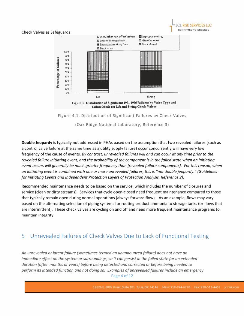
Regardless of type or style of valve, the longest trouble-free service will come from valves sized for the application, not the line size, whereby the disc is stable against the internal stop in the open position or fully closed. When these conditions are met, no fluttering of the disc will occur, resulting in premature failure. Unfortunately, most check valves are selected in the same way on/off valves are selected—based on line size and the desire for the largest Cv available. This ignores the fact that, unlike on/off valves, the flow conditions determine the internal performance of the check valve since its disc is always in the flow stream (The Misunderstood Check Valve, DTI, Inc, Reference 5).
8 Historical Incidents Demonstrate Lessons
A review of incidents helps industrial designers, operators, and managers evaluate their own processes and think more critically about the success and possible failures in process controls. Each of the incidents illustrates the complexity of check valve use in design and reliance.
8.1 Reducing Large Pump Fires Auditing of PHAs demonstrates whether the value of a check valve has been included in the consequence limitations. The most common is a pump seal failure where limited rate of leakage was credited to the safeguard of a check valve. Before a check valve is used to minimize the consequence of pump leaks, its performance should be known. Review of the following case demonstrates this point.
After a fire, [the investigation found that] the check valves on all three pumps were out of order. On one, the seat had become unscrewed. On another, the fulcrum pin was badly worn. On the third, the pin was worn right through and the flap was loose. The valves had not been inspected since the plant was built. Check valves have a bad name among many plant operators. However, this is because many of these valves are never inspected or tested. No equipment, especially that containing moving parts, can be expected to work correctly forever without inspection and repair. When check valves are relied on for emergency isolation, they should be scheduled for regular inspection. (What Went Wrong, Reference 6, page 140).
8.2 Start-up Pressure Testing Fails Another case study indicates the hazards associated with check valves placed in locations where operators have not anticipated impact during prestart-up pressure testing. The check valves prevented the pressure test from entering all parts of the selected process to demonstrate piping integrity. Refer to Figure XX for an illustration of the scenario.
A plant was pressure-tested before startup, but the check valves (nonreturn valves, NRV) in the feed lines to each unit [section of pipe] made it impossible to test the equipment to the left [upstream] of them. A leak of liquefied petroleum gas (LPG) occurred during startup at the point [flow meters and associated flanges] indicated. The three check valves were then replaced by a single one in the common feed line [to the flow meters] (What Went Wrong, Reference 6, Page 250).

Check Valves as Safeguards
Page 9 of 12
Figure 6.1, Pressure Testing Blocked by Check Valves
(What Went Wrong, Reference 6)
8.3 Pressure Profiles Change During Operations Check valves are traditionally placed in the process anytime a connection is made to a utility, such as nitrogen or steam. However, many incidents have occurred through contamination of the utility supply when used by others. The following case illustrates a limited perspective of utility system pressures. If a nitrogen supply is designed for 80 psig, is it truly 80 psig at all times (high demand or end of system piping)?
For example, a small solvent drying unit was designed to operate at a pressure of 30 psig. The drying chambers had to be emptied frequently, so a nitrogen connection was needed. The designer looked up the plant specifications and found that the nitrogen supply operated at a pressure of 80 psig. This was far above the unit’s operating pressure, so the designer assumed there was no danger of the solvent entering the nitrogen main by reverse flow and supplied a permanent connection. (He supplied a check valve in the line, but these are not 100% effective. They would be more effective if they were regularly maintained but rarely are; we cannot expect equipment containing moving parts to work forever without maintenance.) If the designer had asked the operating staff, they would have told him that the unit was to be located near the end of the nitrogen supply line and that its pressure fell to < 30 psig when other units were using a lot of nitrogen. If the designer had ever worked at a plant, he would have known that it is by no means uncommon for nitrogen supply. [The contamination led to a flammable mixture and internal explosion in another unit using the nitrogen to clear a system] (What Went Wrong, Reference 6, Page 483)

Check Valves as Safeguards
Page 10 of 12
8.4 Reactive Hazards When Materials are Mixed Slack flow (no significant flow either direction can lead to more backflow than anticipated/designed since the standard 100 psi differential is not present for check valve closure. For inappropriate mixing outside of a controlled process system, these incidents can present consequences in unusual sections of the plant - in waste streams and in raw material storage. The US Chemical Safety Board prepared a comprehensive study of major accidents on reactive hazards. Refer to the illustration below to understand where the hazards occurred in the process.
Figure 8.1, Reactive Hazards: Equipment Involved in Incidents
(US Chemical Safety Board, Reference 7)
9 Companies Vary on PHA Procedures
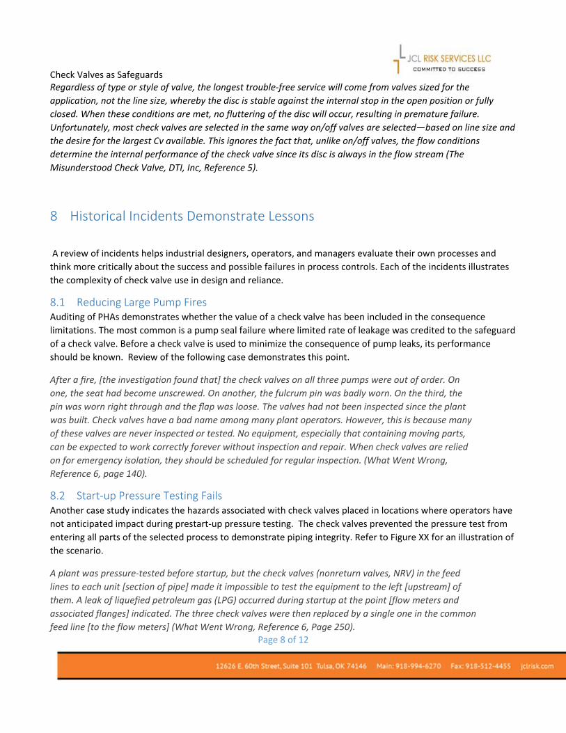
Most companies are aligned in their procedures for PHA safeguard acceptance of process control valves and pressure safety valves (PSV), but check valves as a safeguard are varied and overly simplistic. A PHA Study can too readily apply check valves as a safeguard without verification of reliability and maintenance track record. Where as, control valves and PSV have rigorous maintenance programs. Refer to Table 9.1 for a comparison of company procedures for check valves as safeguards.
Check Valves as Safeguards
Page 11 of 12
Table 9.1 Company Procedures for Check Valves as Safeguards
Company PHA – Procedure for Check Valves
Safeguard Credit
IPL Credit
(PFD) Numerous Companies No Procedure or Policy addressing the use of check
valves in PHAs ? ?
A- Major Oil Refinery and Chemical Complexes
Single check valve. Must be designed to prevent the scenario consequence.
0
A- Major Oil Refinery and Chemical Complexes
Dual check valves in series. Must be designed to prevent the scenario consequence. Additionally, check valves be of a different type or manufacturer and must be part of the facility’s preventive maintenance program.
1 0.1
B- Small Size National Chemical Company – owner of numerous facilities
Single check valve and added to the maintenance list 1
C- Midstream – owner of numerous facilities and other industries
Dual check valves in series. Must be designed to prevent the scenario or consequence. Additionally, check valves be of a different type or manufacturer and must be part of the facility’s preventive maintenance program.
1
D- Small Refining Company with more than one facility
Dual check valves in series. Must be designed to prevent the scenario consequence. Additionally, check valves be of a different type or manufacturer and must be part of the facility’s preventive maintenance program.
1
E- Small Refining Company with more than one facility
No credit for a single check valve 0
F- Midstream Design and Engineering Firm
Credit for single check valve for baseline designs .5
G- Midstream Operations, Numerous Facilities
Two check valves in series (no other specifications); Check for differential pressure at normal operations, >100 psi
1
H- Major Oil Refinery and Chemical Complexes
Single check valves; listed as unreliable
0
H- Major Oil Refinery and Chemical Complexes
Double check valve arrangement when slight reverse flow is tolerable, clean service, >100 psi, consider replacement at each turnaround
1 0.1
Check Valves as Safeguards
Page 12 of 12
10 References: The following references were used in the document and may provide the reader with more information on the subjects presented.
1 Guidelines for Hazard Evaluation Procedures, Page 221, American Institute of Chemical Engineers, Inc., Wiley 2008.
2 Guidelines for Enabling Conditions and Conditional Modifiers in Layer of Protection Analysis, American Institute of Chemical Engineers, Inc., Wiley 2014.
3 Failure Modes and Causes for Swing and Lift Type Check Valves; Oak Ridge National Laboratory, K.L. McElhaney, 1997. https://www.osti.gov/scitech/servlets/purl/621557
4 API Standard 521, Pressure-Relieving and Depressurized Systems, Sixth Edition, January 2014. 5 The Misunderstood Check Valve, Back to Basics, Published in Valve Magazine in 2006, Authors
by DFT, Inc. located in Exton, PA. http://www.dft-valves.com/pdf/literature/general-information/CheckValveBacktoBasicsArticle.pdf
6 What Went Wrong?, Fifth Edition: Case Histories of Process Plant Disasters and How They Could Have Been Avoided (Butterworth-Heinemann/IChemE), 5th Edition; Trevor Kletz
7 Hazard Investigation, Improving Reactive Hazard Management, US Chemical Safety and Hazard Investigation Board, Report No.2001-01-H, Issued October 2002.

Appendix A
PHA - HAZOP Worksheets Node: 1. Failure on delivery of Ammonia (or other hazardous materials) into large pressurized storage vessels
Deviation Causes Consequences CAT Pre-Risk Reduction
Safeguards Mitigated Risk Rank HAZOP
Recommendations
Final Risk Ranking Comment
S P RR S P RR S P RR
Reverse Flow 1.1.1. Operator failure to follow procedure: not securing the block valves at the unloading station between truck unloading hose and the unloading pump (Quick Disconnect does not hold, failure frequency of .1/yr, or the unloading hoses are removed from the piping system after each load is completed)
1.1.1.1. Potential backflow of pressurized liquid ammonia from large storage vessel and reverse flow through unloading pump (due to quick disconnect failure into the unloading area or the loading hose is removed from the piping after each load) and open valves, potential multiple personnel injuries due to large release, potential community impact to toxic gas.
PER I B High 3. Procedure to stop pump at the end of the unload with automated isolation valve closure if pump is not operating.
I D Medium 1. Need 1 additional safeguard
I E Low 1. Need to maintain check valves as critical safety device: review testing period based on the demand rate of weekly unloading of ammonia.
1. Dual Check Valves (metal to metal seating, 10% backflow since never tested, current age of the check valves is 15 years of service) with routine maintenance programs, diverse type and greater than 100 psi differential to close
2. Caution for credit of pump shutdown automatically closed an isolation valve (must include the automated closure, not another operator task to close the discharge of the pump). Many operations do not have this safeguard due to potential for thermal expansion in the piping and pump case while isolated from the process. Location of isolation valve is critical.
1.1.1.2. Potential backflow of pressurized liquid ammonia from large storage vessel and reverse flow through unloading pump (due to quick disconnect failure into the unloading area or the loading hose is removed from the piping after each load) and open valves, potential release of 10% backflow from check valve inability to securely block complete flow, potential personnel exposure at high concentration of ammonia in the load area and injury.
PER III B Medium 3. Procedure to stop pump at the end of the unload with automated isolation valve closure if pump is not operating.
III C Medium 1. Need 1 additional safeguard
III D Low 1. Need to maintain check valves as critical safety device: review testing period based on the demand rate of weekly unloading of ammonia
2. Caution for credit of pump shutdown automatically closed an isolation valve (must include the automated closure, not another operator task to close the discharge of the pump). Many operations do not have this safeguard due to potential for thermal expansion in the piping and pump case while isolated from the process. Location of isolation valve is critical.
Leak or Rupture 1.2.1. Loading hose fails during delivery of ammonia
1.2.1.1. Potential backflow of pressurized liquid ammonia from large storage vessel and reverse flow through unloading pump due to hose failure into the unloading area, potential multiple personnel injuries due to large release, potential community impact to toxic gas.
PER I B High 1. Dual Check Valves (metal to metal seating, 10% backflow since never tested, current age of the check valves is 15 years of service) with routine maintenance programs, diverse type and greater than 100 psi differential to close
I E Low I E Low 1. Need to maintain check valves as critical safety device: review testing period based on the demand rate of weekly unloading of ammonia
2. Operator initiated ESD for Pump shutoff and isolation valve closure (no credit as safeguard, if the ESD uses the same isolation valve as #3 if used in the same scenario).
2. Caution for credit of pump shutdown automatically closed an isolation valve (must include the automated closure, not another operator task to close the discharge of the pump). Many operations

Deviation Causes Consequences CAT Pre-Risk Reduction
Safeguards Mitigated Risk Rank HAZOP
Recommendations
Final Risk Ranking Comment
S P RR S P RR S P RR
Remote location activation to reduce hazard to operator.
do not have this safeguard due to potential for thermal expansion in the piping and pump case while isolated from the process. Location of isolation valve is critical.
4. Critical Task of hose replacement on annual basis and weekly visual test of all sections of the hose (may include periodic pressure test to determine if all parts are functional).
1.3.1. Loading hose fails during delivery of ammonia
1.3.1.1. Potential backflow of pressurized liquid ammonia from large storage vessel and reverse flow through unloading pump due to hose failure into the unloading area, potential release of 10% backflow from check valve inability to securely block complete flow, potential personnel exposure to high concentration of ammonia in the load area and injury.
PER III B Medium 2. Operator initiated ESD for Pump shutoff and isolation valve closure (no credit as safeguard, if the ESD uses the same isolation valve as #3 if used in the same scenario). Remote location activation to reduce hazard to operator.
III D Low III D Low 1. Need to maintain check valves as critical safety device: review testing period based on the demand rate of weekly unloading of ammonia
4. Critical Task of hose replacement on annual basis and weekly visual test of all sections of the hose (may include periodic pressure test to determine if all parts are functional).
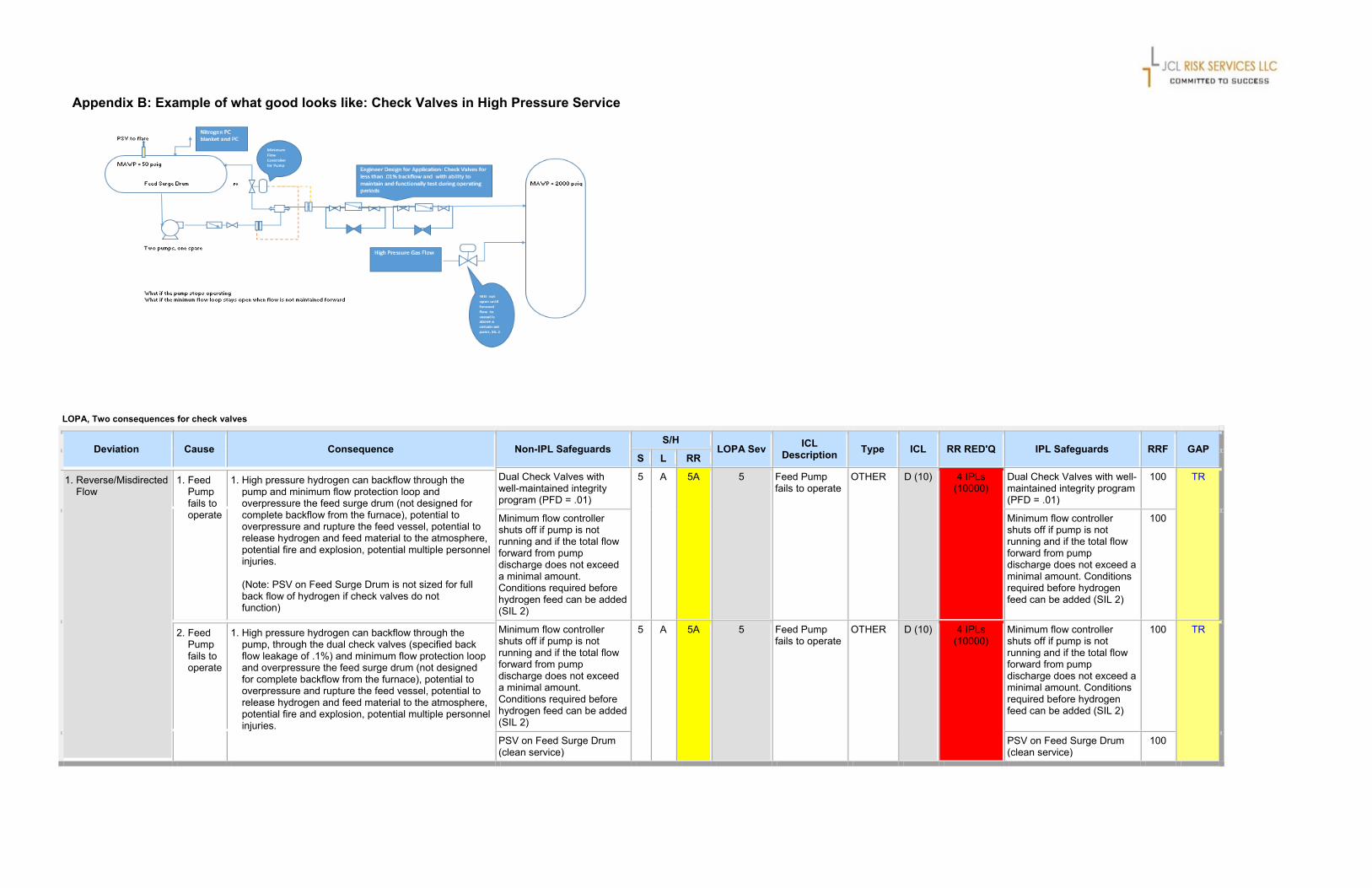
Appendix B: Example of what good looks like: Check Valves in High Pressure Service
LOPA, Two consequences for check valves
Deviation Cause Consequence Non-IPL Safeguards S/H
LOPA Sev ICL Description Type ICL RR RED'Q IPL Safeguards RRF GAP
S L RR
1. Reverse/Misdirected Flow
1. Feed Pump fails to operate
1. High pressure hydrogen can backflow through the pump and minimum flow protection loop and overpressure the feed surge drum (not designed for complete backflow from the furnace), potential to overpressure and rupture the feed vessel, potential to release hydrogen and feed material to the atmosphere, potential fire and explosion, potential multiple personnel injuries. (Note: PSV on Feed Surge Drum is not sized for full back flow of hydrogen if check valves do not function)
Dual Check Valves with well-maintained integrity program (PFD = .01)
5 A 5A 5 Feed Pump fails to operate
OTHER D (10) 4 IPLs (10000)
Dual Check Valves with well-maintained integrity program (PFD = .01)
100 TR
Minimum flow controller shuts off if pump is not running and if the total flow forward from pump discharge does not exceed a minimal amount. Conditions required before hydrogen feed can be added (SIL 2)
Minimum flow controller shuts off if pump is not running and if the total flow forward from pump discharge does not exceed a minimal amount. Conditions required before hydrogen feed can be added (SIL 2)
100
2. Feed Pump fails to operate
1. High pressure hydrogen can backflow through the pump, through the dual check valves (specified back flow leakage of .1%) and minimum flow protection loop and overpressure the feed surge drum (not designed for complete backflow from the furnace), potential to overpressure and rupture the feed vessel, potential to release hydrogen and feed material to the atmosphere, potential fire and explosion, potential multiple personnel injuries.
Minimum flow controller shuts off if pump is not running and if the total flow forward from pump discharge does not exceed a minimal amount. Conditions required before hydrogen feed can be added (SIL 2)
5 A 5A 5 Feed Pump fails to operate
OTHER D (10) 4 IPLs (10000)
Minimum flow controller shuts off if pump is not running and if the total flow forward from pump discharge does not exceed a minimal amount. Conditions required before hydrogen feed can be added (SIL 2)
100 TR
PSV on Feed Surge Drum (clean service)
PSV on Feed Surge Drum (clean service)
100

Appendix C
MITIGATION, so two layers of protection fail first
Check valve is not well maintained 1 Final Event Frequency =
CASE 1Frequency = .2 (wind direction)/Human Failure .1 0.1
Leakage of 1/2 Hole is Equivalent to 7000#/Hr (116#/min)
1
Event Is Small Hole Size Release of Toxic Materials to Atmosphere with Employees in the Near Area
Frequency = .9 0.5Only one EIV, either activated by human or Gas Detector
Human exposure
2
Check Valve Close (poorly maintained
Equivalent to 1/2 Inch Hole Size; 250 psig Differential Frequency = .1 0.1 Final Event Frequency =
1000 Loads in a year, 1 event per 1000 Tasks due to Human Failure to Follow Procedures For Well Trained Human Unload, Event Frequency is 1 per year (could be 10 per year) of incomplete valve shutoff by human, Quick Disconnect is the remaining closure when hose is removed 0.1
Check Valve does not have absolute closure
Frequency = .9 (Prevailing Wind Direction is 80%) or Human Response is .9 0.9
EIV Fails to Close/Open Deluge, DCS Controlled (BPCS Failure); Leakage of 1/2 Inch Hole is Equivalent to 7000#/Hr (116#/min)
1
Event Is Small Hole Size Release of Toxic Materials to Atmosphere with Employees in the Near Area
Human exposure
Frequency = .9 0.9EIV Closes, DCS Controlled (BPCS Failure) No Release of Material to the Atmosphere 1 Final Event Frequency =
No Event Consequence
1
EIV Fails to Close, DCS Controlled (BPCS Failure); Leakage Rate Increases Due Cap/Valve at Loading Station was not Restricted Flow
1 Final Event Frequency =
Frequency = .1, is this known? 0.5
Frequency = .2 (wind direction)/Human Response = .1 1
Difference of Pressure is 200 psig Across Cap/Block Valve That is Leaking;
Human exposureEvent Is 2-inch Hole Size Release Leading to a Large Event if event is not abdated, Leading to elongated Release of Toxic Materials to Atmosphere
0.10Initiating Event Frequency - Task is 3 Times Per Day1/year
Fails Task to Secure Shutoff System, Hoses are disconnectedWhen Departing the Unloading Station
TASK FAILURE: Non-Operator Task, Truck Driver Frequency = .1 0.1 Final Event Frequency =
Frequency = .8 (Prevailing Wind Direction is 80%)/ .9 for human response 1
EIV Fails to Close, DCS Controlled (BPCS Failure); Leakage Rate Increases Due Cap/Valve at Loading Station was not Restricted Flow Assume
response 1
Check Valve Failure, EIV Failure
Gas Detection Detects Leak g Close EIV or Operator Responds to the Alarm and Frequency = .9 0.9
EIV Closes, DCS Controlled (BPCS Failure) No Release of Material to the Atmosphere 1 Final Event Frequency =
No Event
0.9 No Event
Final Event Frequency = no event due to quick disconnect holdingRatio of worst events to each otherWorst events summation
Summation of Injury EventsNo event Frequency =Event frequency
Initiating Event 0.1One Check Valves 1Gas Detect with EIV/ or Operator Response to leak 0.1
Event Frequency of Injury Event= 0.01
No Credit Should be GivenIf Same Operator Task Failure/Operator Required to Close EIV `
Gas Detection Does Not Detect Leak
Operator Fails to perform task to intitate EIV/Deluge
Incomplete Task Leads to Leakage of Material Through
Loading Hose Disconnection at a Rate of 1/2 Inch Hole Size
Gas Detection Detects Leak
Initiates Signal to Close EIV or Operator
Responds to the Alarm and Remotely Activates
EIV in DCS to Close/Deluge
Unloading Ammonia or Other Highly Toxic/Hazardous Materials
Check Valve Fail to Close Equivalent to 2-Inch Hole
Size
Gas Detection Does Not Detect Leak Due to wind
Direction or Human Response to leak and
shutoff of EIV
End-Cap is Not Well Secured on Loading Hose; Shutoff Valve is not closed properly or Does Not Have Tight Shutoff and Valve has Unknown
Leakage (Unrevealed); Loading hose failure is not included based on critical task to maintain hoses (every year replacement).
0.90
Incomplete Task Does Not Lead to Leakage of Material Through
Loading Hose
Simplified PHA
Recommendation of Unloading Operation Stopped to Initiate EIV Closure
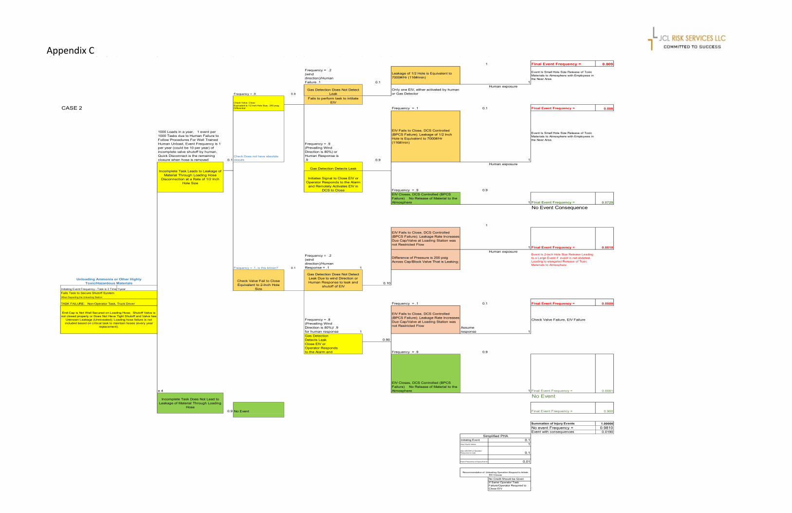
Appendix C 1 Final Event Frequency = 0.009
Frequency = .2 (wind direction)/Human Failure .1 0.1
Leakage of 1/2 Hole is Equivalent to 7000#/Hr (116#/min)
1
Event Is Small Hole Size Release of Toxic Materials to Atmosphere with Employees in the Near Area
Frequency = .9 0.9Only one EIV, either activated by human or Gas Detector
Human exposure
Check Valve Close
CASE 2Equivalent to 1/2 Inch Hole Size; 250 psig Differential Frequency = .1 0.1 Final Event Frequency = 0.008
1000 Loads in a year, 1 event per 1000 Tasks due to Human Failure to Follow Procedures For Well Trained Human Unload, Event Frequency is 1 per year (could be 10 per year) of incomplete valve shutoff by human, Quick Disconnect is the remaining closure when hose is removed 0.1
Check Does not have absolute closure
Frequency = .9 (Prevailing Wind Direction is 80%) or Human Response is .9 0.9
EIV Fails to Close, DCS Controlled (BPCS Failure); Leakage of 1/2 Inch Hole is Equivalent to 7000#/Hr (116#/min)
1
Event Is Small Hole Size Release of Toxic Materials to Atmosphere with Employees in the Near Area
Human exposure
Frequency = .9 0.9EIV Closes, DCS Controlled (BPCS Failure) No Release of Material to the Atmosphere 1 Final Event Frequency = 0.0729
No Event Consequence
1
EIV Fails to Close, DCS Controlled (BPCS Failure); Leakage Rate Increases Due Cap/Valve at Loading Station was not Restricted Flow
1 Final Event Frequency = 0.0010
Frequency = .1, is this known? 0.1
Frequency = .2 (wind direction)/Human Response = .1 1
Difference of Pressure is 200 psig Across Cap/Block Valve That is Leaking;
Human exposureEvent Is 2-inch Hole Size Release Leading to a Large Event if event is not abdated, Leading to elongated Release of Toxic Materials to Atmosphere
0.10
Initiating Event Frequency - Task is 3 Times 1/yearFails Task to Secure Shutoff SystemWhen Departing the Unloading Station
TASK FAILURE: Non-Operator Task, Truck Driver Frequency = .1 0.1 Final Event Frequency = 0.0009
Frequency = .8 (Prevailing Wind Direction is 80%)/ .9 for human response 1
EIV Fails to Close, DCS Controlled (BPCS Failure); Leakage Rate Increases Due Cap/Valve at Loading Station was not Restricted Flow Assume
response 1
Check Valve Failure, EIV Failure
Gas Detection Detects Leak g Close EIV or Operator Responds to the Alarm and Frequency = .9 0.9
e 4
EIV Closes, DCS Controlled (BPCS Failure) No Release of Material to the Atmosphere 1 Final Event Frequency = 0.0081
No Event
0.9 No Event Final Event Frequency = 0.900
Summation of Injury Events 1.00000No event Frequency = 0.9810Event with consequences 0.0190
Initiating Event 0.1One Check Valves 1
Gas with EIV/ or Operator Response to leak 0.1
Event Frequency of Injury Event= 0.01
No Credit Should be GivenIf Same Operator Task Failure/Operator Required to Close EIV `
Gas Detection Does Not Detect Leak p
Fails to perform task to intitate EIV
Incomplete Task Leads to Leakage of Material Through Loading Hose
Disconnection at a Rate of 1/2 Inch Hole Size
Gas Detection Detects Leak
Initiates Signal to Close EIV or Operator Responds to the Alarm
and Remotely Activates EIV in DCS to Close
Unloading Ammonia or Other Highly Toxic/Hazardous Materials
Check Valve Fail to Close Equivalent to 2-Inch Hole
Size
Gas Detection Does Not Detect Leak Due to wind Direction or Human Response to leak and
shutoff of EIV
End-Cap is Not Well Secured on Loading Hose; Shutoff Valve is not closed properly or Does Not Have Tight Shutoff and Valve has
Unknown Leakage (Unrevealed); Loading hose failure is not included based on critical task to maintain hoses (every year
replacement).
0.90
Incomplete Task Does Not Lead to Leakage of Material Through Loading
Hose
Simplified PHA
Recommendation of Unloading Operation Stopped to Initiate EIV Closure

Appendix C
Engineered check valve with soft seat for tight shutoff, well maintained to fit service demand
MITIGATION, so two layers of protection fail first
1 Final Event Frequency = 0.009Frequency = .2 (wind direction)/Human Failure .1 0.1
Leakage of 1/2 Hole is Equivalent to 438 #/Hr (7#/min)
1
Event Is Very Small Hole Size Release of Toxic Materials to Atmosphere with Employees in the Near Area
Severity = Small Toxic Exposure (no lost time)
CASE 3 Frequency = .9 0.9
Only one EIV, either activated by human or Gas Detector
Human exposure
Check Valve Close (well maintained)Equivalent to 1/8 Inch Hole Size; 250 psig Differential Frequency = .1 0.1 Final Event Frequency = 0.0081
1000 Loads in a year, 1 event per 1000 Tasks due to Human Failure to Follow Procedures For Well Trained Human Unload, Event Frequency is 1 per year (could be 10 per year) of incomplete valve shutoff by human, Quick Disconnect is the remaining closure when hose is removed 0.1 Check Valve have absolute closure
Frequency = .9 (Prevailing Wind Direction is 80%) or Human Response is .9 0.9
EIV Fails to Close/Open Deluge, DCS Controlled (BPCS Failure); Leakage of 1/2 Inch Hole is Equivalent to 438 #/Hr (7#/min)
1
Event Is Very Small Hole Size Release of Toxic Materials to Atmosphere with Employees in the Near Area
Severity = Small Toxic Exposure (no lost time)
Human exposure
Frequency = .9 0.90EIV Closes, DCS Controlled (BPCS Failure) No Release of Material to the Atmosphere After Detection 1 Final Event Frequency = 0.0729
No Event Consequence
1
EIV Fails to Close, DCS Controlled (BPCS Failure); Leakage Rate Increases Due Cap/Valve at Loading Station was not Restricted Flow
1 Final Event Frequency = 0.0010
Frequency = .1, is this known? 0.1
Frequency = .2 (wind direction)/Human Response = .1 1
Difference of Pressure is 200 psig Across Cap/Block Valve That is Leaking;
Human exposureEvent Is 2-inch Hole Size Release Leading to a Large Event if event is not abdated, Leading to elongated Release of Toxic Materials to Atmosphere
Severity = Multiple Injuries or Fatalities from Escalating due to long event
0.10Initiating Event Frequency - Task is 3 Times Per Day1/year
Fails Task to Secure Shutoff SystemWhen Departing the Unloading Station
TASK FAILURE: Non-Operator Task, Truck Driver Frequency = .1 0.1 Final Event Frequency = 0.0009
Frequency = .8 (Prevailing Wind Direction is 80%)/ .9 for human response 1
EIV Fails to Close, DCS Controlled (BPCS Failure); Leakage Rate Increases Due Cap/Valve at Loading Station was not Restricted Flow Assume
response 1
Check Valve Failure, EIV Failure Severity = Multiple Injuries or Fatalities from Escalating Toxic Exposure
Gas Detection Detects Leak g Close EIV or Operator Responds to the Alarm and Frequency = .9 0.9
EIV Closes, DCS Controlled (BPCS Failure) No Release of Material to the Atmosphere 1 Final Event Frequency = 0.0081
No Event
0.9 No Event Final Event Frequency = 0.900
Summation of Injury Events 1.0000No event Frequency = 0.9981Event frequency 0.00190
Initiating Event 0.1One Check Valves 0.1Gas Detect with EIV/ or Operator Response to leak 0.1
Event Frequency of Catastrophic Injury Event= 0.001
No Credit Should be GivenIf Same Operator Task Failure/Operator Required to Close EIV `
Gas Detection Does Not Detect Leak p
Fails to perform task to intitate EIV/Deluge
Incomplete Task Leads to Leakage of Material Through Loading Hose Disconnection at a Rate of 1/2 Inch
Hole Size
Gas Detection Detects Leak
Initiates Signal to Close EIV or Operator Responds to the
Alarm and Remotely Activates EIV in DCS to Close/Deluge
Unloading Ammonia or Other Highly Toxic/Hazardous Materials Check Valve Fail to Close Equivalent to 2-Inch Hole Size
Gas Detection Does Not Detect Leak Due to wind Direction or Human Response to leak and
shutoff of EIV
End-Cap is Not Well Secured on Loading Hose; Shutoff Valve is not closed properly or Does Not Have Tight Shutoff and Valve has Unknown Leakage (Unrevealed); Loading hose failure is not included based on critical task to
maintain hoses (every year replacement).
0.90
Incomplete Task Does Not Lead to Leakage of Material Through
Loading Hose
Simplified PHA
Recommendation of Unloading Operation Stopped to Initiate EIV Closure

Appendix C
Engineered dual check valve with soft seat for tight shutoff, well maintained to fit service demand
MITIGATION, so two layers of protection fail first
1 Final Event Frequency = 0.00999Frequency = .2 (wind direction)/Human Failure .1 0.1
Leakage of 1/2 Hole is Equivalent to 438 #/Hr (7#/min)
1
Event Is Very Small Hole Size Release of Toxic Materials to Atmosphere with Employees in the Near Area
Severity = Small Toxic Exposure (no lost time)
CASE 4 Frequency = .9 0.9989Only one EIV, either activated by human or Gas Detector
Human exposure
Dual Check Valve Close (well maintained)
Equivalent to 1/8 Inch Hole Size; 250 psig Differential Frequency = .1 0.1 Final Event Frequency = 0.00899
1000 Loads in a year, 1 event per 1000 Tasks due to Human Failure to Follow Procedures For Well Trained Human Unload, Event Frequency is 1 per year (could be 10 per year) of incomplete valve shutoff by human, Quick Disconnect is the remaining closure when hose is removed 0.1
Check Valve have absolute closure
Frequency = .9 (Prevailing Wind Direction is 80%) or Human Response is .9 0.9
EIV Fails to Close/Open Deluge, DCS Controlled (BPCS Failure); Leakage of 1/2 Inch Hole is Equivalent to 438 #/Hr (7#/min)
1
Event Is Very Small Hole Size Release of Toxic Materials to Atmosphere with Employees in the Near Area
Severity = Small Toxic Exposure (no lost time)
Human exposure
Frequency = .9 0.90EIV Closes, DCS Controlled (BPCS Failure) No Release of Material to the Atmosphere After Detection 1 Final Event Frequency = 0.08091
No Event Consequence
1
EIV Fails to Close, DCS Controlled (BPCS Failure); Leakage Rate Increases Due Cap/Valve at Loading Station was not Restricted Flow
1 Final Event Frequency = 0.00001
Frequency = .0011 based on tes 0.0011
Frequency = .2 (wind direction)/Human Response = .1 1
Difference of Pressure is 200 psig Across Cap/Block Valve That is Leaking;
Human exposureEvent Is 2-inch Hole Size Release Leading to a Large Event if event is not abdated, Leading to elongated Release of Toxic Materials to Atmosphere
Severity = Multiple Injuries or Fatalities from Escalating due to long event
0.10Initiating Event Frequency - Task is 3 Times Per Day1/year
Fails Task to Secure Shutoff SystemWhen Departing the Unloading Station
TASK FAILURE: Non-Operator Task, Truck Driver Frequency = .1 0.1 Final Event Frequency = 0.00001
Frequency = .8 (Prevailing Wind Direction is 80%)/ .9 for human response 1
EIV Fails to Close, DCS Controlled (BPCS Failure); Leakage Rate Increases Due Cap/Valve at Loading Station was not Restricted Flow Assume
response 1
Check Valve Failure, EIV Failure Severity = Multiple Injuries or Fatalities from Escalating Toxic Exposure
Gas Detection Detects Leak Close EIV or Operator Responds to the Alarm and Frequency = .9 0.9
EIV Closes, DCS Controlled (BPCS Failure) No Release of Material to the Atmosphere 1 Final Event Frequency = 0.00009
No Event
0.9 No Event Final Event Frequency = 0.90000
Summation of Injury Events 1.00000No event Frequency = 0.99998Event frequency 0.00002
Initiating Event 0.1One Check Valves 0.1Gas Detect with EIV/ or Operator Response to leak 0.1
Event Frequency of Catastrophic Injury Event= 0.001
No Credit Should be GivenIf Same Operator Task Failure/Operator Required to Close EIV `
Gas Detection Does Not Detect Leak
Operator Fails to perform task to intitate EIV/Deluge
Incomplete Task Leads to Leakage of Material Through
Loading Hose Disconnection at a Rate of 1/2 Inch Hole Size
Gas Detection Detects Leak
Initiates Signal to Close EIV or Operator
Responds to the Alarm and Remotely Activates
EIV in DCS to Close/Deluge
Unloading Ammonia or Other Highly Toxic/Hazardous Materials
Dual Check Valve Fail to Close Equivalent to 2-Inch
Hole Size
Gas Detection Does Not Detect Leak Due to wind
Direction or Human Response to leak and
shutoff of EIV
End-Cap is Not Well Secured on Loading Hose; Shutoff Valve is not closed properly or Does Not Have Tight Shutoff and Valve has Unknown
Leakage (Unrevealed); Loading hose failure is not included based on critical task to maintain hoses (every year replacement).
0.90
Incomplete Task Does Not Lead to Leakage of Material Through
Loading Hose
Simplified PHA
Recommendation of Unloading Operation Stopped to Initiate EIV Closure

When the upstream level controller fails- or the vessel pressure goes high, is there anything to protect the steam system
Consider low flow shutoff and inclusion of check valve in an accessible loop for inspection
and maintenance

UNREVEALED FAILURES- DOUBLE JEOPARDY?
JCL Risk Services is a fully integrated
risk services firm that is a subsidiary of JCL Service
Company. The management team of JCL Risk
Services has been engaged in the management of safety
and risk mitigation for over 30 years.
Our clients choose us for our experience,
practical approach, and ability to bring forth
high quality solutions to their most challenging
risk management issues.
PROGRAM AUDITS & REVIEWS
Our quality-focused professionals will review the existing process safety information. After the review, we will design an audit that takes a comprehensive snapshot of your existing PSM and RMP process that will result in an actionable plan to bring the necessary program elements into compliance with both regulatory and company requirements.
Our experts will provide support for the following:
■■ PSM System Elements■■ RMP Requirements, Scenarios, and Updates■■ Code Compliance■■ Spill Prevention■■ Flammable and Combustible Liquids Control■■ Fire Protection Requirements■■ Ventilation■■ Gas Detection■■ Community and Mutual Aid Integration
COMPREHENSIVE MANAGEMENT SYSTEMS
Our experienced professionals will bring start-up facilities into compliance and mature facilities to the next level of operations improvement. We understand the requirements and communicate in such a way that everyone understands how their facility processes work.
We provide support for the following:
■■ Management Systems Development■■ Operating Procedures Development■■ RMP Development■■ Facility Siting & Release Modeling■■ PSI Updates■■ Process Hazard Analysis■■ PSM and RMP Audits■■ Pre-Startup Safety Reviews
jcl r isk .com

Jim Lefler President & CEO
David Jones Director, Process Safety Services
Donna Seabolt Administrative Manager
Oklahoma12626 East 60th Street, Suite 101, Tulsa, OK 74146
Office 918-994-6270
Texas16225 Park Ten Place, Suite 500, Houston, TX 77084
Office 713-338-3421
jc l r isk .com
JCL RISK SERVICES LLCA Subsidiary of JCL Service Company LLC
Our Senior Safety Consultants with JCL Safety Services can provide expert support
in project reviews, incident investigations, and
comprehensive safety services management.
We routinely assist our clients with:■■ Turnaround Safety Planning■■ Facility Audits■■ New Start-ups■■ Maintenance Operations
SAFETY MANAGEMENT & CONSULTING
jclsafety.com

Kay A Modi Senior Process Safety Consultant Summary Ms. Modi has 30+ years of petroleum and petrochemical experience and is well-seasoned in Process Safety Management Systems and Practices and large project management. She possesses a rare blend of process engineering, process hazard analysis, facility siting evaluations, risk analysis (consequence and quantitative), emergency release modeling, employee exposure modeling, incident investigation, and environmental consequences. Ms. Modi has participated in new plant start-ups, FEED/new construction reviews, plant optimizations, plant turnarounds, and corporate risk oversight. She has extensive knowledge of chemical and petroleum refining process technologies. Large projects have included staff and technical responsibilities for major pipeline (gas, liquids, terminals, and gas facilities) systems database development of assets and EHS regulatory tracking. Asset and due diligence assessments of facilities for transactions with site visits. Management of engineering and administrative staff for safety services companies. Short-term contract to provide environmental and health regulatory affairs management within major pipeline corporation during staff transitions. Prior to working with JCL Risk Services, Ms. Modi worked with Shell Oil and Shell Chemical Company at the Deer Park, Texas and Mobile, Alabama locations. Ms. Modi worked with the teams for the startup of pesticide with waste destruction facilities and for the startup of high pressure hydrotreating units. Ms. Modi has process engineering experience with vacuum distillation, catalytic systems, hydrotreating, gas processing, various chemical processes, and marine terminals. Ms. Modi has performed numerous risk dispersion modeling projects associated with low level exposures to carcinogenic materials and catastrophic releases with highly toxic chemicals stored in significant quantities (OSHA/EPA/WHO thresholds). Ms. Modi oversaw engineering project’s SHE assessments for consulting firms. She has developed risk assessments for SHE in various countries and predominantly in the petroleum upstream and downstream processes for new business and new construction. Selected Projects
• Facility Siting Evaluations to reduce the footprint of overpressure sources • Major Pipeline (Oil and Gas Systems, Marine Terminals) Database developed for EHS regulatory and asset
tracking of 50+ facilities plus minor assets • Development of PHA/LOPA/Enabling Modifiers procedures with Quantitative Methods for setting Targeted
Mitigation Event Likelihoods for new construction projects to optimize SIS designs in specialty chemical processes
• Quantitative risk assessments for explosions from LOC within chemical process units with highly flammable raw materials
Education Bachelor of Science, Chemical Engineering – University of Missouri-Rolla