check out these great features
TRANSCRIPT
Sun Certified Data Management Engineer(emphasis on VERITAS VolumeManager)Version 3.0.0
Notice: While every precaution has been taken in the preparation of this material, neither the author norCramsession.com assumes any liability in the event of loss or damage directly or indirectly caused by anyinaccuracies or incompleteness of the material contained in this document. The information in this documentis provided and distributed "as-is", without any expressed or implied warranty. Your use of the information inthis document is solely at your own risk, and Cramsession.com cannot be held liable for any damagesincurred through the use of this material. The use of product names in this work is for information purposesonly, and does not constitute an endorsement by, or affiliation with Cramsession.com. Product names usedin this work may be registered trademarks of their manufacturers. This document is protected under US andinternational copyright laws and is intended for individual, personal use only. For more details, visit our legal page.
Check out these great features at www.cramsession.com
> Discussion Boardshttp://boards.cramsession.com
> Info Centerhttp://infocenter.cramsession.com
> SkillDrillhttp://www.skilldrill.com
> Newslettershttp://newsletters.cramsession.com/default.asp
> CramChallenge Questionshttp://newsletters.cramsession.com/signup/default.asp#cramchallenge
> Discounts & Freebieshttp://newsletters.cramsession.com/signup/ProdInfo.asp
Your TrustedStudy Resource
for Technical
CertificationsWritten by experts.The most popular
study guides on the web.
In Versatile PDF file format
Sun Certified Data Management Engineer (emphasis on VERITAS Volume Manager)
Sun Certified Data Management Engineer (emphasis on VERITAS Volume Manager) Version 3.0.0
Abstract: This study guide will help you prepare for the Sun Certified Data Management Engineer (emphasis on VERITAS Volume Manager), exam 310-101. Exam topics include: RAID Overview and Introduction to Sun Hardware RAID Storage Systems; Sun Storage Systems Architecture Overview; The SunStorEdge T3 Array; RAID Manager; VERITAS Volume Manager; Solstice DiskSuite[tm] Software with Hardware RAID; Installation; VERITAS Volume Manager Operations; and Performance Management and Troubleshooting.
Find even more help here:
05/24/02
© 2002 All Rights Reserved – BrainBuzz.com 1

Sun Certified Data Management Engineer (emphasis on VERITAS Volume Manager)
Contents: RAID Overview and Introduction to Sun Hardware RAID Storage Solutions............. 4
Sun Storage Philosophy ............................................................................... 4 Key Components of Sun Storage Architecture ................................................. 4
SCSI and FC-AL ...................................................................................... 4 RAID Explained .......................................................................................... 5 StorEdge A1000 Components ....................................................................... 5 StorEdge D1000 Components ....................................................................... 6 The Difference Between A1000 and D1000 Arrays ........................................... 6 Sun StorEdge 3500 RAID Controller Functions ................................................ 6
Controller System Level Indicators............................................................. 6 Controller Status LED’s............................................................................. 7 Back Panel ............................................................................................. 7
StorEdge A3500 Components ....................................................................... 7 RAID Manager ............................................................................................... 8
RAID Manager Features ............................................................................... 8 Installation ................................................................................................ 8 RAID Manager Glossary of Terms .................................................................. 9
Drive Group............................................................................................ 9 LUN....................................................................................................... 9 Cache Memory .......................................................................................10 Parity ...................................................................................................10 RAID Module..........................................................................................10 RDAC Driver ..........................................................................................10
Command Line Interface.............................................................................10 Device Naming Conventions.....................................................................11
Using a Hot Spare......................................................................................11 Deleting a Drive Group............................................................................11 Creating a New Drive Group.....................................................................12 Check Status Message Log.......................................................................12
Drive Recovery..........................................................................................13 Maintenance and Tuning .............................................................................13
StorEdgeT3 Features .....................................................................................14 Supported Configurations............................................................................15 Partner Group Defined and Failover Operation................................................15 T3 Administration ......................................................................................16 T3 FRU Options .........................................................................................17 Software that Supports the T3.....................................................................17 pSOS .......................................................................................................18 Standard Admin Command Examples ...........................................................18 Identifying Faults in pSOS...........................................................................19 Creating a Volume on T3 ............................................................................20
05/24/02
© 2002 All Rights Reserved – BrainBuzz.com 2

Sun Certified Data Management Engineer (emphasis on VERITAS Volume Manager)
Making the T3 Array Available to Solaris ....................................................20 T3 Drive LED Decoding............................................................................21 Power and Cooling Unit ...........................................................................21 Controller LED and Channel LED Decoding .................................................22 Unit Interconnect Controller .....................................................................22
Software for Performing Configuration and Monitoring StorEdge Systems...........23 VERITAS Volume Manager..............................................................................23
Hardware and Software RAID ......................................................................23 Integrating Volume Manager and Hardware RAID ...........................................23
The purpose of Alternate Pathing ..............................................................24 Volume Manager Overview..........................................................................25
Installation ............................................................................................26 Disk Encapsulation Versus Initialization .....................................................26 Mirroring ...............................................................................................26
Volume Manager Operations ...........................................................................27 Create Simple, Striped and RAID 5 Volumes ..................................................28
Some Notes of Interest ...........................................................................28 Guidelines for Optimized Stripe Width for Sequential and Random I/O............29
Remove a Volume......................................................................................29 Replace a Failed Disk Drive .........................................................................29 Remove a Mirror from a Volume...................................................................30 Create a Disk Group and Add Disks to It .......................................................30
Initialise a Disk Drive fo ..........................................................................30 r Volume Manager Use ............................................................................30
Add a Dirty Region Log to Disk ....................................................................30 Modify Volume Ownership and Permissions....................................................30
Solstice Disksuite..........................................................................................31 Differences Between VERITAS Volume Manager and Solstice Disksuite ..............31
Performance Management and Troubleshooting.................................................32 List the Three Types of RAID 5 Write Procedures ............................................32 Troubleshooting Storage Faults....................................................................32 Administrative Tools to Troubleshoot and Isolate Storage-Related Problems .......33
05/24/02
© 2002 All Rights Reserved – BrainBuzz.com 3
Sun Certified Data Management Engineer (emphasis on VERITAS Volume Manager)
RAID Overview and Introduction to Sun Hardware RAID Storage Solutions
Sun Storage Philosophy
All information for all users and all accounts must be available at all times.
Key Components of Sun Storage Architecture
The key components are:
• Reliability
• Availability
• Serviceability (RAS) SCSI and FC-AL
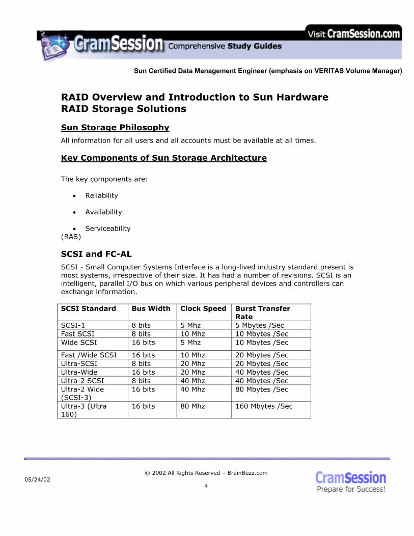
SCSI - Small Computer Systems Interface is a long-lived industry standard present is most systems, irrespective of their size. It has had a number of revisions. SCSI is an intelligent, parallel I/O bus on which various peripheral devices and controllers can exchange information. SCSI Standard Bus Width Clock Speed Burst Transfer
Rate SCSI-1 8 bits 5 Mhz 5 Mbytes /Sec Fast SCSI 8 bits 10 Mhz 10 Mbytes /Sec Wide SCSI 16 bits 5 Mhz 10 Mbytes /Sec
Fast /Wide SCSI 16 bits 10 Mhz 20 Mbytes /Sec Ultra-SCSI 8 bits 20 Mhz 20 Mbytes /Sec Ultra-Wide 16 bits 20 Mhz 40 Mbytes /Sec Ultra-2 SCSI 8 bits 40 Mhz 40 Mbytes /Sec Ultra-2 Wide (SCSI-3)
16 bits 40 Mhz 80 Mbytes /Sec
Ultra-3 (Ultra 160)
16 bits 80 Mhz 160 Mbytes /Sec
05/24/02
© 2002 All Rights Reserved – BrainBuzz.com 4

Sun Certified Data Management Engineer (emphasis on VERITAS Volume Manager)
Fiber Channel operates on fiber-optic cable and copper wire and is often used for more than disk I/O. It is a protocol that supports high-speed systems and network interconnects based on various protocols such as SCSI, TCP/IP, and ATM. FC-AL (Fiber Channel-Arbitrated Loop) is a very common topology using a shared gigabit transport. Thus bandwidth is dependant on the numbers of devices on the loop. It can be used with hubs, which act like their network counterparts. The advantage of FC-AL is that it supports greater node address-ability, up to 127 nodes on a single host. It also supports existing SCSI protocols, uses a unique naming convention based on WWN (World Wide Numbers) and requires simplified wiring. RAID Explained
While there has been plenty written about RAID, here are the common RAID levels and their definitions: RAID 0 – Disk Striping – High I/O performance, no redundancy RAID 1 – Mirroring – Two or more identical disks RAID 2 – Hamming Code Correction – Parallel mapping and protection RAID 3 – Striping Dedicated Parity – Like RAID 2 but with parity RAID 4 – Independent Reads, Writes – Parity on a single disk RAID 5 – Disk Striping with Parity – Distributed parity on all disks; generally poor write performance RAID 6 – Striping with distributed parity – Can handle two disk failures at the expense of severe performance penalty, as there are two independent forms of check data StorEdge products only support RAID levels 0,1,5, while RAID Manager supports 0,1,3,5. StorEdge A1000 Components
The A1000 includes a RAID Controller and a Single Differential SCSI interface with two Ultra Wide SCSI buses for disk drives and has dual redundant power supplies and cooling modules. It uses split back plane, but the RAID controller connects to both with two host adaptors.
05/24/02
© 2002 All Rights Reserved – BrainBuzz.com 5
Sun Certified Data Management Engineer (emphasis on VERITAS Volume Manager)
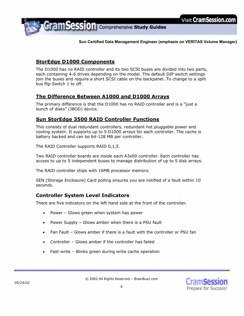
StorEdge D1000 Components
The D1000 has no RAID controller and its two SCSI buses are divided into two parts, each containing 4-6 drives depending on the model. The default DIP switch settings join the buses and require a short SCSI cable on the backpanel. To change to a split bus flip Switch 1 to off.
The Difference Between A1000 and D1000 Arrays
The primary difference is that the D1000 has no RAID controller and is a “just a bunch of disks” (JBOD) device. Sun StorEdge 3500 RAID Controller Functions
This consists of dual redundant controllers, redundant hot pluggable power and cooling system. It supports up to 5 D1000 arrays for each controller. The cache is battery backed and can be 64-128 MB per controller. The RAID Controller supports RAID 0,1,5. Two RAID controller boards are inside each A3x00 controller. Each controller has access to up to 5 independent buses to manage distribution of up to 5 disk arrays. The RAID controller ships with 16MB processor memory. SEN (Storage Enclosure) Card polling ensures you are notified of a fault within 10 seconds. Controller System Level Indicators
There are five indicators on the left hand side at the front of the controller.
• Power – Glows green when system has power
• Power Supply – Glows amber when there is a PSU fault
• Fan Fault – Glows amber if there is a fault with the controller or PSU fan
• Controller – Glows amber if the controller has failed
• Fast-write – Blinks green during write cache operation
05/24/02
© 2002 All Rights Reserved – BrainBuzz.com 6

Sun Certified Data Management Engineer (emphasis on VERITAS Volume Manager)
Controller Status LED’s
Each controller has ten LED’s that indicate its individual status. ● ●● ●●●●●●● From left to right:
• Amber Fault LED – On when controller has error
• Green Power LED – On when power to controller
• Green Heartbeat LED – Blinks at 2 sec intervals There are 7 Green Status LED’s which display in patterns:
• Solid all on – Controller held in reset
• Chasing light pattern – Firmware upgrade in process
• Cycling light pattern – Indicates that controller is held at boot Two lights in first bank of status lights indicate failure:
• ●● ●● ● ●● ● - Main processor memory failure
• ●● ●● ● ●●● - RAID parity SIMM failure
Back Panel
Both controllers plug directly into the A3x00 controller module back panel. This interconnects to all others components in the controller module. The A3500 does not support any Ethernet connections but does have a serial RS-232 connection. Controller SCSI id’s – default are 4 for the bottom and 5 for the top.
StorEdge A3500 Components
Can have 1x5 (1 RAID Controller and 5 D1000 Arrays) Can have 2 x7 (2 RAID Controllers and 7 D1000 Arrays)
A3500FC – Converts differential SCSI to single ended SCSI and performs all RAID functions as in the A3500 but supports Fiber channel connections.
05/24/02
© 2002 All Rights Reserved – BrainBuzz.com 7

Sun Certified Data Management Engineer (emphasis on VERITAS Volume Manager)
RAID Manager
RAID Manager Features
RAID Manager is used to configure the disks in Hardware RAID arrays. Virtual Disks – Groups of devices presented as one to the OS:
• Striping
• Mirroring
• RAID 5
• Hot Spares Disk Grouping – Multiple drives that are assigned to LUNS (Logical Units) GUI – Is supported Free-Space Management – Based on physical partitions
Installation
Install the following packages:
• SUNWosafw – Storage Array firmware
• SUNWosar - Storage Array root
• SUNWosau - Storage Array /usr
• SUNWosamn – Storage Arrray man pages
05/24/02
© 2002 All Rights Reserved – BrainBuzz.com 8
Sun Certified Data Management Engineer (emphasis on VERITAS Volume Manager)
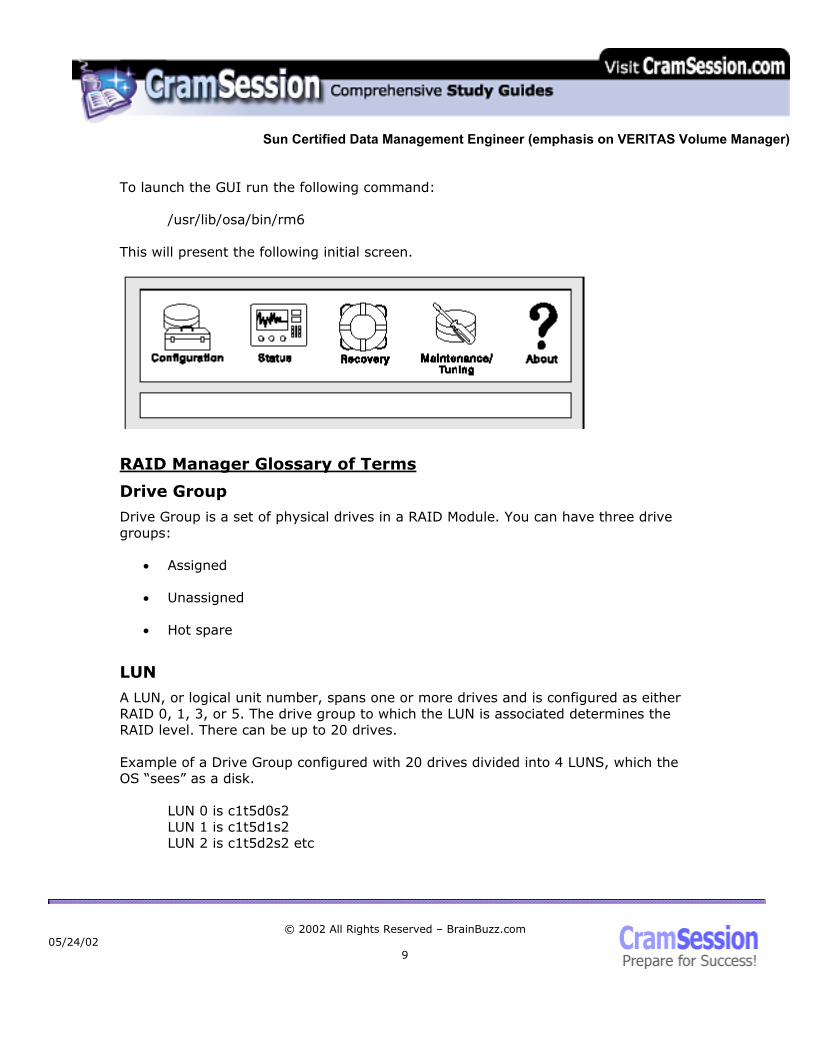
To launch the GUI run the following command:
/usr/lib/osa/bin/rm6 This will present the following initial screen.
RAID Manager Glossary of Terms
Drive Group
Drive Group is a set of physical drives in a RAID Module. You can have three drive groups:
• Assigned
• Unassigned
• Hot spare
LUN
A LUN, or logical unit number, spans one or more drives and is configured as either RAID 0, 1, 3, or 5. The drive group to which the LUN is associated determines the RAID level. There can be up to 20 drives. Example of a Drive Group configured with 20 drives divided into 4 LUNS, which the OS “sees” as a disk.
LUN 0 is c1t5d0s2 LUN 1 is c1t5d1s2 LUN 2 is c1t5d2s2 etc
05/24/02
© 2002 All Rights Reserved – BrainBuzz.com 9
Sun Certified Data Management Engineer (emphasis on VERITAS Volume Manager)
Cache Memory
Cache memory is used as a high-speed data area before staging to disk. Writes are made to cache and acknowledged back to the OS and then written to disk as required. Reads check cache first and, if hits are made, there’s no interaction with the disks at all, resulting in much faster reads.
Parity
It is extra information written to allow the system to rebuild data in the event of a failure. Note: Only RAID 3 and 5 use this.
RAID Module
A RAID Module is a group of disk drives with one or two controllers that are physically connected. RDAC Driver
This is a redundant disk array controller that manages I/O on RAID Modules with two controllers so that, in event of failure, I/O gets re-directed to the remaining controller.
Command Line Interface
The following commands are located in /usr/sbin/osa:
• drivutil – Manages drives and luns
• fwutil – Used for firmware downloads etc.
• healthck – Reports health of RAID Modules
• lad – List array devices
• logutil – Formats error log to screen
• nvutil – Control nvram settings
• parityck – Parity check and repair
05/24/02
© 2002 All Rights Reserved – BrainBuzz.com
10
Sun Certified Data Management Engineer (emphasis on VERITAS Volume Manager)
• RAIDutil – Perform lun and hot spare creation
• rdautil – Redundant controller functions; i.e., load balancing
• storutil – Host-store utility Device Naming Conventions
/dev/rdsk and /dev/osa/dev/rdsk are both linked to the /devices file. There are:
• Max 16 LUNS per RAID Module
• Max 32 LUNS per HBA
Using a Hot Spare
From the configuration menu, select unassigned drives -->> click create hot-spare (the button with a + sitting on a drive) --> select number of drives in pool. If you click options, it will show you which ones have been selected. NOTE: You should have one per hot spare SCSI Channel for each RAID Module. Remember, a host spare cannot replace a bigger disk so make sure your hot spare is as big as the largest disk on the SCSI channel.
Deleting a Drive Group
Open the configuration menu, select the desired drive group and click on the delete button, which looks like a trash can. If you want to delete an individual LUN in a drive group, just open the drive group, select the LUN and click delete.
05/24/02
© 2002 All Rights Reserved – BrainBuzz.com
11
Sun Certified Data Management Engineer (emphasis on VERITAS Volume Manager)
Creating a New Drive Group
Select Configuration ---> select unassigned drives ---> click Create LUN >> select RAID Level >> select number of drives -->> select number of LUNS If you click on options you can --->> select Drives --->> caching Parameters----- There are three choices of caching:
1. Write Caching – Data written to cache
2. Write Cache Mirroring – Data written to cache and mirrored to other controller
3. Cache without batteries – Enables the use of cache even if there is no battery which puts data at risk unless you have a UPS
---> Select Segment Size --->> Select LUN Assignment --->> Once you are happy with the selection click create. Check Status Message Log
From the GUI, click on Status. This gives you three options:
1. Message Log Viewing (/usr/lib/osa/rmlog.log)
2. LUN reconstruct monitoring – You can change the Reconstruct Rate
3. Performance Monitoring – You can set the Polling Interval Message Log – displays historical messages for RAID Module events. Click on event and then click Show Details to get more information. You can change log settings to move the log file, change log max size, and when to check RAID modules. This default is 5 minutes.
05/24/02
© 2002 All Rights Reserved – BrainBuzz.com
12

Sun Certified Data Management Engineer (emphasis on VERITAS Volume Manager)
Drive Recovery
This comes in two flavours, depending on the RAID level you are using and type of failure. Degraded Mode - With RAID 1, 3, and 5 a failed disk puts the LUN into degraded mode but data is still available. Dead Mode – This is single disk failure in RAID 0 or multiple failures in RAID 1, 3, 5. Normally you have to replace faulty drive(s) and restore data on replacement drives to fix this type of failure. To recover a drive, you should do one of the following:
• Open the recovery window ---- > Click on Health Check (Stethoscope)
• If a failure is found, you can click on the failure and then click “show procedure” for how to fix it
Maintenance and Tuning
Here are some recommendations:
• Firstly, you should keep firmware as up-to-date as possible
• You can change the LUN Reconstruct Rate from Reconstruct Performance – System Performance
• Balance LUN assignments between controllers automatically or manually
• Change controller mode from active /passive to active/active
• Set the automatic parity check or repair option
05/24/02
© 2002 All Rights Reserved – BrainBuzz.com
13
Sun Certified Data Management Engineer (emphasis on VERITAS Volume Manager)
StorEdgeT3 Features
The StorEdge T3 includes the following:
• 256 MB cache that adapts to the workload
• High performance RAID XOR engine
• FC-AL copper to FC-AL optical using Media Interface Adaptor
• Redundant PSU, Fans, FC-AL interconnects, Cache Mirrored in partner group
• All FRU’s hot pluggable including: o Fans o Controllers o Power Supplies
• 9 x Dual Ported Fiber Channel disks per tray
• Very scalable can add multiple T3 trays including expansion units which do
not have any controller installed
• Supports Ethernet connection and RS-232 for admin
05/24/02
© 2002 All Rights Reserved – BrainBuzz.com
14
Sun Certified Data Management Engineer (emphasis on VERITAS Volume Manager)
Supported Configurations
The T3 supports one or two logical volumes with an array of 9 disks. These two volumes can be either RAID 0,1 or 5. The default T3 shipped configuration is one RAID 5 volume. T3’s operate under some configuration rules:
• LUNS must consist of a continuous block of disks
• A disk can only be in one LUN If a hot spare is used, it must be disk 9. Partner Group Defined and Failover Operation
Two T3’s with controllers can be paired together into a partner group. The trays are connected to each other over interconnects. This provides for path fail over, controller fail over, cache mirroring and increased performance. There can be two types of failover:
• Path
• Controller In the case of a path failure, the I/O directed to that controller will timeout and is redirected by VERITAS or AP to the alternate controller. This controller will then realise that the data is for disks not local to its array. In this case, it verifies that it can still talk to the other controller and assumes ownership of the partner LUN. All data now passes to it for the other controller and is redirected to the correct disks over the backend interconnects. Once the path comes back on line, the software automatically fails back to the original controller, which then assumes ownership of the LUN. In the case of a controller failure, it initially acts the same as the loss of a path. The difference comes when the controller, which is receiving I/O it doesn’t expect, tries to communicate to its partner controller. This times out so it takes some more drastic action. It stops using cache and write operations directed to disk and immediately writes any cached data to disk. It also stops mirroring cache if setup to do so.
05/24/02
© 2002 All Rights Reserved – BrainBuzz.com
15

Sun Certified Data Management Engineer (emphasis on VERITAS Volume Manager)
In the case of a failure of the master controller, the alternate takes over the IP address, host name and MAC address assigned to the master and enables its Ethernet port, so it becomes the administration controller. Once you replace the failed controller, it boots automatically and gets I/O redirected back as you would expect, but the Master controller does not regain any admin function until it is next reset. T3 Administration
T3’s are easily managed through a number of means. You can use Sun Component Manager, which provides a Web front end. Component manager gives you access to a system event log, a graphical view of the array, complete with Status LED’s. You can also run a health check and create volumes from this GUI. You can also telnet to the T3 array and use command line options to perform maintenance and administration.
Example: sunbox# telnet t3name Trying 192.168.40.15... Connected to t3name Escape character is '^]'. pSOSystem (192.168.40.15) Login: root Password
T300 Release 1.17a 2001/05/07 13:39:18 (192.168.40.15) Copyright (C) 1997-2001 Sun Microsystems, Inc. All Rights Reserved.
t3name:/:<1>
05/24/02
© 2002 All Rights Reserved – BrainBuzz.com
16

Sun Certified Data Management Engineer (emphasis on VERITAS Volume Manager)
T3 FRU Options
With the T3 there are a number of Field Replaceable Units (FRU’s). The most obvious are the disk drives themselves. There are 9 per tray and there cannot be less than this under normal circumstances. If one disk was removed, you would have 30 minutes before the T3 shutdowns to replace the disk. This is because of cooling requirements. In the T3 array, the operating system of the T3 resides in the first 200MB of each disk, with the first disk in the master controller being used under normal circumstances. If that fails, the Master controller will try each disk in turn until it can locate a valid system area. The Controller is the smart element in the T3 and provides such things as the fiber connection, Ethernet connection, RAID Management and cache. Each controller has a PowerPC 603 chip installed and 32MB of System RAM. There is one per tray. The UIC or Unit Interconnect Card provides the T3 access to its partner over loops. The proprietary interconnect cable allows the T3 to be linked or daisy chained together. There are normally two in a tray, one for each loop. The PCU or power cooling unit on each T3 has two fans, a power supply, and two batteries. Each T3 tray has two PCU’s. The T3 can operate with 3 of the 4 fans operational. One the neat things about the T3 is that, because it has a mid-plane, one power supply can fail and the other can power the fans and battery using the mid-plane. The mid-plane in the T3 has all FRU’s connect to it. In the rare event the mid-plane needs to be replaced, the whole chassis would be replaced. With this in mind, Sun has published a MTBF (mean time between failure) of 7.8 million hours. Software that Supports the T3
Volume Manager 3.0.2c and above support the T3 as does any version of Solstice Disksuite.
05/24/02
© 2002 All Rights Reserved – BrainBuzz.com
17
Sun Certified Data Management Engineer (emphasis on VERITAS Volume Manager)
pSOS
pSOS, or Plug in Silicon Operating System, is similar to UNIX: it supports login, file system , daemon processes and admin files. As mentioned before, it resides on the 200MB System Area of each disk in the array. The following daemons are running on the T3:
• Ftpd
• telnetd
• timed
• pshd
• httpd
• snmpd
• schd pfile is the local file system and contains /etc and /web directories. Note: The T3 only supports one account, the root one. Key thing to note is that most of the T3 commands, except help and reset, are non-re-entrant; i.e., cannot be executed multiple times in different shells. Standard Admin Command Examples
fru stat – Displays FRU status fru list – Displays FRU firmware levels, model information port listmap – Displays volume and Fiber port information refresh –s – Displays battery information sys stat – Displays which is the master Controller proc list – Displays running processes; i.e., reconstruct
05/24/02
© 2002 All Rights Reserved – BrainBuzz.com
18

Sun Certified Data Management Engineer (emphasis on VERITAS Volume Manager)
vol verify – Checks data parity on RAID 1 and RAID5 volumes and can be used with the fix switch vol mode – Displays cache operation and if cache is mirrored vol recon volume-name from_standby – Forces reconstruct vol stat – Displays volume status by numbers 0 Drive is mounted 2 Drive is present 3 Drive is spun-up 4 Drive is disabled 7 Invalid System Area on drive 9 The drive is not present D Drive is disabled and being reconstructed S The drive is being substituted id read unpcun – Displays battery related information, including life span date – Sets the date tzset - Sets the time zone
Identifying Faults in pSOS
To identify faults, the key commands to use are fru stat and vol stat. fru stat will display all components and their status and is the command you would normally use. vol stat will tell you if the volume on the T3 is still mounted and the individual status of each drive.
05/24/02
© 2002 All Rights Reserved – BrainBuzz.com
19

Sun Certified Data Management Engineer (emphasis on VERITAS Volume Manager)
Creating a Volume on T3
There are a few steps to follow when creating a volume on the T3. Once you have telneted onto the T3 as the root account, which by default has no password, you need to define the volume you wish to create. Volumes parameters include:
• Volume size
• RAID level
• Host spare availability vol add volume_name data u2d1-8 RAID 5 standby u2d9 Creates the volume using eight disks, in a RAID 5 configuration with hot spare. vol init volume_name data Initialises the volume. vol mount volume-name Mounts the volume ready for use. Making the T3 Array Available to Solaris
Assuming the T3 volumes are mounted, you must update the device tree by doing one of the following:
• Luxadm
• devfsadm
• reboot -- -r
• boot –r ( from the ok prompt) Once you have done this you must label the drive by running format. Select the drive and answer yes to the label prompt. Type type and select 0 auto configure and then label the drive.
05/24/02
© 2002 All Rights Reserved – BrainBuzz.com
20

Sun Certified Data Management Engineer (emphasis on VERITAS Volume Manager)
T3 Drive LED Decoding
Drive Activity Green Drive Status Description Off Off The drive is not installed or
recognized Solid Off Drive OK but idle Flashing Off The drive is OK, active N/A Solid Drive recon or firmware
download N/A Slow Blink Drive is OK to replace Slow Blink Off Drive spinning down/up Power and Cooling Unit
AC LED PS LED Description Off Off Power is OFF Amber Off Power is turned off but has
AC Green Green PCU is on AC Power N/A Amber, Solid Shutdown in progress Green Off T3 is in shutdown mode N/A Amber Slow Blink PCU Failed. OK to replace Green Blinking Battery is charging
05/24/02
© 2002 All Rights Reserved – BrainBuzz.com
21
Sun Certified Data Management Engineer (emphasis on VERITAS Volume Manager)
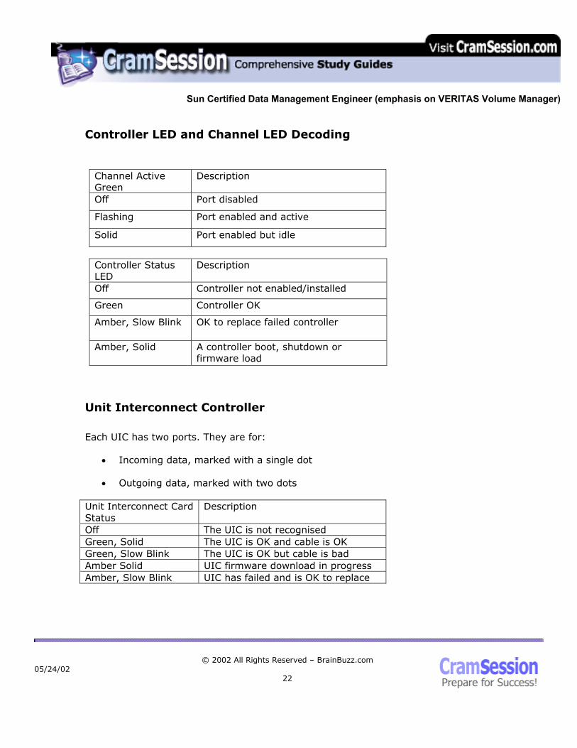
Controller LED and Channel LED Decoding
Channel Active Green
Description
Off Port disabled
Flashing Port enabled and active
Solid Port enabled but idle
Controller Status LED
Description
Off Controller not enabled/installed
Green Controller OK
Amber, Slow Blink OK to replace failed controller
Amber, Solid A controller boot, shutdown or firmware load
Unit Interconnect Controller
Each UIC has two ports. They are for:
• Incoming data, marked with a single dot
• Outgoing data, marked with two dots Unit Interconnect Card Status
Description
Off The UIC is not recognised Green, Solid The UIC is OK and cable is OK Green, Slow Blink The UIC is OK but cable is bad Amber Solid UIC firmware download in progress Amber, Slow Blink UIC has failed and is OK to replace
05/24/02
© 2002 All Rights Reserved – BrainBuzz.com
22

Sun Certified Data Management Engineer (emphasis on VERITAS Volume Manager)
Software for Performing Configuration and Monitoring StorEdge Systems
Sun provide Component Manager, which is a java and web enabled management tool for monitoring T3 and A5x00 arrays. It supports:
• Alarm notification
• Remote reporting
• Visual representation of device status
VERITAS Volume Manager
Hardware and Software RAID
Some of the benefits of using software RAID with hardware RAID are improved:
• Availability
• Performance
• Manageability You can do such things as configure RAID 5 volumes on your array then stripe in Volume Manager for increased performance without having to worry about a lack of resilience normally associated with RAID 0. Integrating Volume Manager and Hardware RAID
As the OS does not “see” the hardware RAID array as anything but a disk device, it is easy to integrate hardware RAID with Volume Manager. Follow the normal procedure, putting the disk under VERITAS control as detailed below.
05/24/02
© 2002 All Rights Reserved – BrainBuzz.com
23

Sun Certified Data Management Engineer (emphasis on VERITAS Volume Manager)
The purpose of Alternate Pathing
Alternate Pathing (AP) provides redirection of a failed interface or connection. The Solaris AP provides host-path redundancy for T3 partner pairs, and dual attached A series hardware RAID arrays. Note that it provides active/passive channels only and no load balancing. VERITAS includes Dynamic Multipathing (DMP) version 3, which provides load balancing and resilience for A1000 and A3500FC arrays. Note that when using T3 arrays DMP does not provide load balancing. In the T3’s case, when using partner groups, DMP provides dual paths to each controller as follows:
• Primary channel to master controller for volumes on its disk array and secondary for volumes on the alternate masters array should it lose its channel
• Primary channel to alternate master for volumes in its disk array and
secondary for volumes in the master controllers array should it lose its channel
So DMP assumes two host loop paths to a SUN storage T3 Partner group, where each data path functions as the primary path for its own disks. In Solaris, a partner pair of T3’s is shown below as four devices. You can see by the last 4 digits of the WWN the two paths to each T3. Note the WWN is generated off the MAC address of each tray.
05/24/02
© 2002 All Rights Reserved – BrainBuzz.com
24

Sun Certified Data Management Engineer (emphasis on VERITAS Volume Manager)
For example # format Searching for disks...done
AVAILABLE DISK SELECTIONS:
0. c0t0d0 <SUN18G cyl 7506 alt 2 hd 19 sec 248>
/sbus@60,0/QLGC,isp@0,10000/sd@0,0
1. c1t2d0 <SUN-T300-0117 cyl 34901 alt 2 hd 224 sec 128>
/sbus@61,0/SUNW,socal@0,0/sf@0,0/ssd@w50020f2300003728,0
2. c1t2d1 <SUN-T300-0117 cyl 34901 alt 2 hd 224 sec 128>
/sbus@61,0/SUNW,socal@0,0/sf@0,0/ssd@w50020f2300003728,1
3. c3t1d0 <SUN-T300-0117 cyl 34901 alt 2 hd 224 sec 128>
/sbus@65,0/SUNW,socal@0,0/sf@0,0/ssd@w50020f2300003e44,0 4. c3t1d1 <SUN-T300-0117 cyl 34901 alt 2 hd 224 sec 128> /sbus@65,0/SUNW,socal@0,0/sf@0,0/ssd@w50020f2300003e44,1 Specify disk (enter its number): Volume Manager Overview
Volume Manager acts as an intermediary between the OS and the actual array or disk. It allows the creation of “virtual” disks, which it calls volumes. Volumes are simply containers. They contain plexes, which are copies of a volumes data and can be referred to as mirrors, as VM calls one copy of data mirrors. These plexes are made up of subdisks, which are contiguous portions of real disks similar to Solaris partitions but there is no real limit on subdisks.
In summary: A disk group is a container for Volumes, which are made up of Plexes, which are made up of Subdisks, the smallest unit in VM.
05/24/02
© 2002 All Rights Reserved – BrainBuzz.com
25
Sun Certified Data Management Engineer (emphasis on VERITAS Volume Manager)
Installation
To install VERITAS Volume Manager, add the following packages from CD: VRTSvxvm - Drivers, daemons and utilities (required) VRTSvmman - Manual pages VRTSvmdoc – Docs VRTSvmsa - Storage Administrator (provides GUI and remote management) Then run vxinstall and provide license information. When you run vxinstall, VM identifies the boot disk and describes a procedure for bringing it under VM control as the rootdisk in rootdg, the default disk group. It does this by encapsulating the disk; i.e., preserving all data. VM brings a disk under its control by creating two partitions on the disk:
• Private region of 1 Cylinder in size
• Public region that is the remainder of the disk It removes all other partitions except Slice 2. Solaris Volume Manager uses the VTOC to determine size of the disk.
Disk Encapsulation Versus Initialization
The disk can either be encapsulated or initalised. With encapsulation, data is preserved by converting partitions to volumes, whereas with initialization, data is destroyed. Note that to encapsulate you require two free Solaris partitions available on the disk with enough space to be encapsulated.
Mirroring
Volume Manager supports three way mirroring. It is best to stripe A1000’s and A3500 and then mirror them in VM.
05/24/02
© 2002 All Rights Reserved – BrainBuzz.com
26
Sun Certified Data Management Engineer (emphasis on VERITAS Volume Manager)
Volume Manager Operations
Here are some general Volume Manager commands: vxassist – Creates and manages volumes vxdctl – Controls volume config daemon vxdg – Manages disk groups vxdiskadd – Adds disks for use with VM vxedit – Creates, removes, modifies VM records vxinstall – Installs VM vxdiskadm – Command line admin interface vxdmpadm – Command line DMP admin interface vxevac – Evacuates a disk vxprint – Reports configuration of volumes to screen vxdisk – Lists disk information vxrecover – Performs recovery operations vxresize – Resizes Volumes vxtrace – Traces disk/volume information vxtask – Lists running VM tasks vxunroot – Removes VM from root volumes vxstat – Displays VM stats vxrootmir – Mirrors the root disk vxplex – Performs operations on plexes; i.e., Mark Stale, Failing, etc. vxmend – Mends simple problems in configuration records
05/24/02
© 2002 All Rights Reserved – BrainBuzz.com
27

Sun Certified Data Management Engineer (emphasis on VERITAS Volume Manager)
vxr5check – Checks RAID 5 volume parity vxreattach – Reattaches drives that have become accessible vxrelocd – Monitors VM for failures and relocates failed subdisks Create Simple, Striped and RAID 5 Volumes
To create a simple volume of 20MB in the Diskgroup datadg, called vol01, run: vxassist –g datadg make vol01 20m To create a striped volume of 500MB in the Diskgroup datadg, called vol02, run: vxassist –g datadg make vol02 500m layout=stripe ncols=4 stripeunit=64k datadg01 To create a RAID 5 Volume of 100MB in the Diskgroup datadg, called vol03, run: vxassist –g datadg make vol03 100m layout=RAID-5 ncols=4 stripeunit=64k !datadg01 To create a mirrored volume with log of 400MB in the Diskgroup datadg, called vol04, run: vxassist –g datadg make vol04 400m layout=mirror,log
Some Notes of Interest
Specifying a disk will force VM to attempt to use it. Excluding a disk requires a ! before the disk name as shown above. If you don’t select a disk, VM will choose one. Concatenated is the default layout; i.e., simple volume. A Striped Volume requires at least two disks default stripe size is 64KB. RAID 5 requires 3 disks, 4 if logging is enabled. If you do not specify a diskgroup, then the root diskgroup rootdg is always assumed.
05/24/02
© 2002 All Rights Reserved – BrainBuzz.com
28
Sun Certified Data Management Engineer (emphasis on VERITAS Volume Manager)
Guidelines for Optimized Stripe Width for Sequential and Random I/O
Where possible, use Write cache for all Luns. Also, where possible, use VxFS. Use 16KB strip unit size in RAID Manager for RAID 5 Luns. Use 64KB in volume Manager when creating stripes. Note that, by default, Volume Manager uses half K blocks in a layout so that 64KB is 128 blocks. When setting up for random I/O, the recommendation is that each unit of I/O should complete in each stripe column; i.e., each disk. To do this, you should set your stripe unit size equal or greater than the size of your I/O. For example, if your I/O is 8KB and you have four disks, each stripe unit is at least 8KB so that the total stripe width is 32KB. When setting up for sequential I/O, all disks should participate in I/O so you should match your total stripe width to I/O size. For example, if your I/O is 256KB and you have 4 disks, 256 / 4 = 64KB which is the size of your stripe unit. So the total stripe width for this case is 256KB. Remove a Volume
Command line removal of vol01 in diskgroup datadg: vxassist –g datadg remove vol01 OR vxedit –g datadg –rf rm vol01 The –r removes the plexes, while the –f forces the volume to stop for the removal. Replace a Failed Disk Drive
Use vxdiskadm option 5, which guides you through the disk removal and replacement procedure. This removes the disk then initialises a new disk and writes the disk media name to the replacement disk and starts a vxrecover.
05/24/02
© 2002 All Rights Reserved – BrainBuzz.com
29
Sun Certified Data Management Engineer (emphasis on VERITAS Volume Manager)
Remove a Mirror from a Volume
Command line for removal of one of the mirrors of vol05 in diskgroup datadg: vxassist –g datadg remove mirror vol05 If this reduces the copies to 1, any log will be deleted as well. Create a Disk Group and Add Disks to It
To create a new disk group called newdg and add disks, list them as below: vxdg init newdg newdg01=c0t0d0,c3t4d2 etc
Initialise a Disk Drive fo
r Volume Manager Use
From the command line run: Run vxdiskadm and chose option 1 vxdisksetup disk=disk media name
Add a Dirty Region Log to Disk
To add a DRL to vol04 on diskgroup datadg, run: vxassist –g datadg addlog vol04 Modify Volume Ownership and Permissions
The default permissions and ownership are user root, group root and permissions 0600, resulting in read and write permissions for only the root. You can change this using vxassist when you make a volume: vxassist –g notesdg make vol01 20m user=root group=notes mode=0660 To modify this setting, use vxedit. Note that the mode is in octal, same as Solaris permissions. vxedit set user=username group=groupname mode=xxx volumename
05/24/02
© 2002 All Rights Reserved – BrainBuzz.com
30

Sun Certified Data Management Engineer (emphasis on VERITAS Volume Manager)
Solstice Disksuite
A logical disk is called a metadevice and logical devices can be made up of one or more partitions. Solaris addresses these metadevices as follows: /dev/md/dsk/d0 /dev/md/rdsk/d0 A metatrans device is supported, thus enabling ufs logging. There must be at least three state database replicas, which can be on two disks. A replica is stored near the beginning of a disk like a label. Each is 517KB and should be on a dedicated partition. Metadevices can be:
• RAID5
• Mirrored
• Concat
• Stripe
• Concat stripe Differences Between VERITAS Volume Manager and Solstice Disksuite
• VERITAS provides DMP whereas Disksuite provides AP
• VERITAS uses soft partitions, Disksuite uses hard partitions; i.e., Solaris max
of 8
• Solstice uses metasets whereas Volume Manager uses disk groups
• VM uses private area on all disks whereas Disksuite configures database replicas and must maintain a quorum of three drives
05/24/02
© 2002 All Rights Reserved – BrainBuzz.com
31

Sun Certified Data Management Engineer (emphasis on VERITAS Volume Manager)
• With VM, it is easy to create volumes. This is difficult under Solstice
• Volume Manager must use VxFS if logging is required
• RAID 5 under solstice must use logging
Performance Management and Troubleshooting
List the Three Types of RAID 5 Write Procedures
There are three ways an array can write under RAID 5. They are, listed in order of efficiency:
• Full-stripe write – This occurs when all the data for the modified stripe exists in cache. This is the best method, as the array does not have to read from the disk to complete the parity generation.
• Partial-stripe write – In this case, not all the information for the modified
stripe exists in cache so the array must read in the remaining data to generate the new parity information
• The other method is different from the two listed above in that the array
determines which data bits have changed and the changes only the corresponding parity bits. To do this, the array must perform two reads, two writes and two parity calculations. This is known as a read-modify-write.
Troubleshooting Storage Faults
• Check Revisions of firmware
• Run tests on suspect loop, array or disk
• Identify and locate failing FRU
• Replace FRU as required
• Check revisions of FRU and upgrade if necessary
• Run a test with Component Manager or pSOS if applicable
• Create a configuration snapshot file if necessary
05/24/02
© 2002 All Rights Reserved – BrainBuzz.com
32

Sun Certified Data Management Engineer (emphasis on VERITAS Volume Manager)
Administrative Tools to Troubleshoot and Isolate Storage-Related Problems
• If you have them, use StorTools and System Monitor to help you troubleshoot
Special thanks to Steve Lawrence
for contributing this Cramsession.
05/24/02
© 2002 All Rights Reserved – BrainBuzz.com
33