che october 2012
TRANSCRIPT

October
2012
www.che.com
PAGE 26
Process
Vacuum Systems
Dry Solids Mixing
Facts at your
Fingertips:
Fans and Blowers
Steam Systems
Focus on
Gas Detection
Ethylene from
Shale Gas
CONTINUOUS
VERSUS
BATCH
PROCESSING
PAGE 34
action loves reactionChemical reactions require chemical catalysts. As the
global leader in chemical catalysts, BASF acts through
continuous product and process innovations in collaborative
partnerships with our customers. The result is a broad
chemical catalyst portfolio backed by dedicated customer
and technical service and enabled through the strength of
BASF - The Chemical Company.
At BASF, we create chemistry.
www.catalysts.basf.com/process
� Adsorbents� Fine Chemical Catalysts � Environmental Catalysts � Catalysts for Fuel Cells � Catalysts for Oleochemicals & Other Biorenewables � Oxidation & Dehydrogenation Catalysts � Petrochemical Catalysts � Polyole� n Catalysts � Re� ning Catalysts � Syngas Catalysts � Custom Catalysts
Circle 5 on p. 60 or go to adlinks.che.com/40272-05

Dual Bulk Bag Weigh Batch Eductor conditions,discharges by weight, andblends into a liquid stream
Bulk-Bag-To-Bin WeighBatching System discharges,de-lumps and feeds materialgravimetrically
Continuous Loss-of-WeightBulk Bag Unloader allowscontinuous gravimetricdischarging
Bulk Bag Unloader forPneumatic Conveyors hassurge hopper with rotaryairlock feeder for metering
Sanitary Bulk BagDischarger with patentedUSDA-accepted flow control valve cleans rapidly
AA-0
417
Now save time, money and space with BULK-OUT™multi-function dischargers
Condition, de-lump, screen, feed, weigh batch, combine with liquids, and convey as you discharge,with a custom-integrated, performance-guaranteed discharger system from Flexicon
USA
[email protected] 888 FLEXICON
See the full range of fast-payback equipment at flexicon.com: Flexible Screw Conveyors, Pneumatic Conveying Systems, Bulk Bag Unloaders, Bulk Bag Conditioners, Bulk Bag Fillers, Bag Dump Stations, Drum/Box/Container Dumpers, Weigh Batching and Blending Systems, and Automated Plant-Wide Bulk Handling Systems
©2012 Flexicon Corporation. Flexicon Corporation has registrations and pending applications for the trademark FLEXICON throughout the world.
*Patent(s) granted and/or pending.
CHILE
UK
AUSTRALIA
SOUTH AFRICA
+56 2 415 1286+44 (0)1227 374710 +61 (0)7 3879 4180+27 (0)41 453 1871
Bulk Bag Unloader forPneumatic Conveyors hassurge hopper with non-flow-through pick-up adapter
Bulk Bag Conditioner-Unloader loosens solidifiedmaterial, then discharges, de-lumps and conveys
Half Frame Unloaders with Conveyor or Airlockrequire forklift, eliminatingcost of upper frame
Combination Bulk BagDischarger and ManualDumping Station has multi-purpose hopper interface
Split-Frame allows loading of bag frame or rigid bins onto subframe within 4 in.(100 mm) of ceiling
Unlimited configurations:All Flexicon dischargers are available
as fully enclosed, dust-free systems withdurable industrial finishes or in stainless
steel finished to food, dairy, pharmaceuticalor industrial standards, and as weigh
batching systems complete with automatedcontrols and pneumatic or mechanical
conveying systems.
Flexicon innovations:• SPOUT-LOCK® clamp ring*: forms high-integrity
seal between clean sides of bag and equipment• TELE-TUBE® telescoping tube: maintains
constant downward tension on spout as bagempties/elongates, promoting complete discharge
• POWER-CINCHER® flow control valve*: allowsretying of partially empty bags dust-free bycinching spout concentrically.
Circle 8 on p. 60 or go to adlinks.che.com/40272-08

Sulzer Chemtech Ltd
Process Technology
4123 Allschwil, Switzerland
Phone +41 61 486 3737
www.sulzerchemtech.com
Sulzer Chemtech USA, Inc.
Tulsa, OK 74131, USA
Phone +1 918 446 6672
Sulzer Chemtech Pte. Ltd.
Singapore 629845
Phone +65 6515 5500
•Yougetthebestfromourinnovativerangeoftechnologies:distillation–evaporation–liquid-liquidextraction–crystallization–membraneseparation–hybridsolutions–polymerproduction.
•Jointlywefullydevelopyourprocesssolutionfromfirstconceptandpilottestingtoaninstalledplantwithguaranteedperformance.
Whetheryouareactiveinthechemical,pharmaceutical,biofuelsorfood&beverageindustry,weareheretosupportyou.
Proven Process
Solutions for You
CT.38e-1
Circle 20 on p. 60 or go to adlinks.che.com/40272-20

CHEMICAL ENGINEERING WWW.CHE.COM OCTOBER 2012 3
OCTOBER 2012 VOLUME 119, NO. 10IN THIS ISSUE
COVER STORY
26 Cover Story Acids Handling General guidelines on materials, storage, pumping and other concerns for the proper and safe handling of acids
NEWS
11 Chementator A cryogenic turbo mill generates rubber powder from recycled tires; A concept for making gasoline from air; A polymersome that releases its cargo where needed; Progress for making smart membranes; and more
16 Newsbriefs CFATS administration needs improvement, testimony argues; Shell to construct world’s first oil-sands CCS project; ECHA seeks public consultation; and more
17 Newsfront Shale Gas Ushers in Ethylene Feed Shifts Growth in ethane cracking has wide effects for the CPI
20 Newsfront A Steamy Situation Many chemical processors do not realize the full potential of their steam systems
ENGINEERING
25 Facts at Your Fingertips Fans and Blowers This one-page reference guide discusses major considerations in setting up and operating fans and blowers
34 Feature Report From Batch to Continuous Processing Continuous flow reactors can provide many benefits over batch processes. This article answers why and how
41 Solids Processing Blending, Sampling and Segregation Don’t
discount these aspects of dry solids mixing, which represent three sides of the same coin
47 Environmental Manager Reduce Hazards in Process Vacuum Systems
Reduce explosion risks, and chemical and physical hazards, to ensure safe operation of vacuum pumps and related systems
ONLY ON CHE.COM
More on: Shale Gas news; A Web Exclusive article on Environmental Permitting Issues
for Dryers and Kilns; New Products;
Latest news; and morewww.che.com
EQUIPMENT & SERVICES
23 Focus on Gas Detection Measure thousands of gases in the field; Fixed gas
detector is protected against dust and water; Detector approved for underground mining; Carbon dioxide detector protects against dangerous leaks; and more
24D-1 ChemInnovations Show Preview (Domestic edition) The 3rd annual
ChemInnovations conference and tradeshow will take place in New Orleans on November 14–15. The show will feature a conference program, news on emerging technologies and more. Featured subjects of the Chementator Lightning Round, a live, on-stage interview with experts on innovative technologies, are described
24I-1 New Products (International edition) Let this company collect and
analyze machinery vibration data; Power supplies with large current outputs; New features offered in this latest CFD software; This wireless vibration transmitter now has ATEX approval; This oxygen analyzer is certified for hazardous areas; and more
COMMENTARY
5 Editor’s Page Water and energy are linked The interdependence between
water and energy is explored
55 The Fractionation Column Who says ChE careers aren’t
adventurous A cautionary tale from the FRI technical director on traveling abroad
DEPARTMENTS
Letters 6
Calendar . . . . . . . 8–9
Who’s Who . . . . . . 62
Reader Service . . . 60
Economic Indicators . . . . 63–64
ADVERTISERS
Product Showcase . 56
Classified Advertising . . . 57–59
Advertiser Index . . 61
COMING IN NOVEMBER
Look for: Feature Re-ports on Dust Safety; and Variable Frequency Drives for Centrifugal Pumps; Engineering Practice articles on Anti-surge valve selec-tion and sizing; and Chemical Injection Sys-tems; a Focus on Ana-lyzers; News articles on the Employment Outlook; and Pressure Measurement and Con-trol; and more
Cover: David Whitcher

1-800-624-8765 • [email protected]
Get more performance from Echotel. www.magnetrol.com
The more you rely on Echotel®, the less you’ll worry if your current tuning fork is calibrated to the
right density – or can measure your low-density liquids at all. Unlike tuning fork technology, Echotel
Model 961 Single–Point and Model 962 Dual–Point ultrasonic level switches provide continuously
accurate and reliable level control independent of the liquid density. With the capability to read
any density, even below 0.6 SG, and no DIP switch to configure, you’ll be assured of superior
overfill prevention across your tank inventory.
Density calibration is just one less thing to worry about when you choose Echotel® Ultrasonic Level Switches.
Echotel Gap Technology Offers MORE Than Tuning Fork Technology
MORE Efficiency – Dual–point capability allows two-point detection from the same unit.
MORE Versatility – Echotel can be remote mounted for easy access and control.
MORE Information – Separate relay outputs for diagnostics and level alarms.
MORE Advanced Diagnostics – Thorough testing of electronics, transducer, crystals, and for electromagnetic noise.
Circle 14 on p. 60 or go to adlinks.che.com/40272-14
Editor’s Page
This month marks the 40th anniversary of the Clean Water Act (CWA),
the primary federal law regulating discharges of pollutants into U.S.
waters. As far as the developed world’s water priorities go, a great
deal has changed since 1972. For one thing, the top challenge back then
was eliminating releases of toxic substances. Today, that challenge is ar-
guably being met, and we are now getting more serious about minimizing
the consumption of water altogether.
Despite that growing intention, a sometimes-overlooked fact is that
water and energy consumption are interdependent. Whether the context
is the chemical process industries (CPI) or much broader, the truth is this:
The more water that is consumed, the more energy that is needed, and
vice versa. The connection can be illustrated very clearly by looking at an
everyday example from the U.S. Environmental Protection Agency (EPA;
Washington, D.C.; www.epa.gov). Approximately 4% of electricity demand
in the U.S. is devoted simply to moving and treating drinking water and
wastewater. Conversely, it takes 3,000–6,000 gal/yr of water to power just
one 60-W, incandescent light bulb for 12 h/d.
In the CPI, water requires significant energy input for pumping, heat-
ing, process uses and treatment (both on the front and back ends). So even
if cost savings in water use are not incentive enough on their own, in many
cases reductions in energy use could make up the difference, and some-
times more. Meanwhile, shifts in energy and water supplies promise to
increase the stakes moving forward.
Consider for a moment that emerging energy supplies are not likely to
require less water per unit of energy, and in some cases they will require
much more. Take the practice of hydraulic fracturing, for instance, which
uses vast volumes of water and is increasingly being applied to both oil
and gas exploration. Meanwhile, many emerging biobased routes to both
energy and chemicals — including those from crops or algae — are based
on mechanisms that need water to grow. Perhaps innovation in these areas
will improve this state of affairs, but it is doubtful that anything would
result in a net decrease in global, or even regional, water demand.
Now think about the fact that as fresh-water resources become more
scarce, the energy required to deliver a gallon of water could itself be on
the rise. If demand increases enough to require that significantly more
water be sourced through desalination processes, that would in itself mag-
nify the energy drain. Desalination is power intensive.
With that in mind, it is time that the CPI start looking at water and
energy bills together. In addition to reducing operating costs today, it
can also get a head start on a brewing problem that is poised to get even
more profound.
This month’s Equipment News Roundup (p. 20), presents new innovations
that can achieve big benefits in one of the most obvious connections between
water and energy efficiency: steam.
Meanwhile, in the CE archives (www.che.com) there is a wealth of prac-
tical, how-to guidance on this subject. For instance, the
article Wastewater Treatment: Energy-Conservation Op-
portunities* presents details on five specific proposals:
• Use variable frequency drives (VFDs) to adjust the speed of electric motors to meet process demand
• Replace old electric motors• Maximize the production and use of biogas as a fuel• Switch to a distributed effluent cooling system• Optimize aeration and oxygen transfer ■
Rebekkah Marshall
* www.che.com/technical_and_practical/5404.html
Water and energy are linked
Winner of Eight Jesse H. Neal Awards for Editorial Excellence
Published since 1902An Access Intelligence Publication
PUBLISHER
BRIAN NESSEN Group [email protected]
EDITORS
REBEKKAH J. MARSHALLEditor in [email protected]
DOROTHY LOZOWSKIManaging [email protected]
GERALD ONDREY (Frankfurt)Senior [email protected]
SCOTT JENKINSAssociate [email protected]
CONTRIBUTING EDITORS
SUZANNE A. [email protected]
CHARLES BUTCHER (U.K.)[email protected]
PAUL S. GRAD (Australia)[email protected]
TETSUO SATOH (Japan)[email protected]
JOY LEPREE (New Jersey)[email protected]
GERALD PARKINSON (California) [email protected]
INFORMATION SERVICES
CHARLES SANDSSenior DeveloperWeb/business Applications [email protected]
MARKETING
JAMIE REESBYMarketing DirectorTradeFair Group, [email protected]
JENNIFER BRADYMarketing Coordinator TradeFair Group, Inc. [email protected]
ART & DESIGN
DAVID WHITCHERArt Director/Editorial Production [email protected]
PRODUCTION
STEVE OLSONDirector of Production &[email protected]
JOHN BLAYLOCK-COOKEAd Production [email protected]
AUDIENCE DEVELOPMENT
SARAH GARWOODAudience Marketing [email protected]
GEORGE SEVERINE Fulfillment [email protected]
JEN FELLING List Sales, Statlistics (203) [email protected]
EDITORIAL ADVISORY BOARD
JOHN CARSONJenike & Johanson, Inc.
DAVID DICKEYMixTech, Inc.
MUKESH DOBLEIIT Madras, India
HENRY KISTERFluor Corp.
TREVOR KLETZLoughborough University, U.K.
GERHARD KREYSA (retired)DECHEMA e.V.
RAM RAMACHANDRAN (Retired) The Linde Group
CHEMICAL ENGINEERING WWW.CHE.COM OCTOBER 2012 5
HEADQUARTERS
88 Pine Street, 5th Floor, New York, NY 10005, U.S.Tel: 212-621-4900 Fax: 212-621-4694
EUROPEAN EDITORIAL OFFICES
Zeilweg 44, D-60439 Frankfurt am Main, GermanyTel: 49-69-9573-8296 Fax: 49-69-5700-2484
CIRCULATION REQUESTS:
Tel: 847-564-9290 Fax: 847-564-9453Fullfillment Manager; P.O. Box 3588, Northbrook, IL 60065-3588 email: [email protected]
ADVERTISING REQUESTS: see p. 60
For photocopy or reuse requests: 800-772-3350 or [email protected] reprints: Wright’s Media, 1-877-652-5295, [email protected]
ACCESS INTELLIGENCE, LLC
DON PAZOURChief Executive Officer
ED PINEDOExecutive Vice President & Chief Financial Officer
MACY L. FECTOExec. Vice President, Human Resources & Administration
HEATHER FARLEYDivisional President, Access Intelligence
ROBERT PACIOREKSenior Vice President, Chief Information Officer
SYLVIA SIERRASenior Vice President, Corporate Audience Development
MICHAEL KRAUSVice President, Production and Manufacturing
STEVE BARBERVice President, Financial Planning and Internal Audit
GERALD STASKOVice President/Corporate Controller
4 Choke Cherry Road, Second FloorRockville, MD 20850 • www.accessintel.com
More opinions on ChE education
I would like to contribute to the discussion on “practical”
ChE education (CE, September 2012, p. 5–6). After gradu-
ation, I as well didn’t know what a pipe flange was, nor a
gasket, didn’t know how to read a pump curve, didn’t know
how to size a relief valve and so on. I could have learned
more that applies to the CPI [chemical process industries]
in an operator training (process technology) curriculum
that’s offered at the local community college than I ever
learned in college. The problem as I see it is that the faculty
of universities are trying to train students to become like
them. But very few actually go on to become teaching pro-
fessors since the salaries are better in industry.
While I agree with Mr. Blanton’s suggestion that intern-
ships are the way to go, opportunities are limited these
days. Those lucky individuals who get an internship repre-
sent a tiny percentage of those who are eligible. The rest of
us (like myself at the time) end up in manual labor summer
jobs with no practical experience upon graduation.
I disagree with Mr. Bloss’s assumption that the “engineer-
ing field is so broad that it is difficult for any university to
meet the need of every industry.” Isn’t the ChE curriculum
itself broad enough supposedly to meet the needs of all
chemical engineers? Are you telling me that a centrifugal
pump used in the plastics industry is different from one used
in a biofuels plant? Common practical basics that can and
should be taught to engineers bound for industry.
I also believe there is no reason why you can’t combine
engineering theory and practicality in one four-year cur-
riculum. The amount of math and theory taught in a stan-
dard ChE program is far too excessive for those going on to
industry, and there’s no reason why you can’t trim the fat.
Like you say, eliminate the Laplace Transforms and the
linear algebra that nobody’s ever going to use. (I did apply a
differential equation one time on the job, but that was early
on and I still had to go back to the textbook to remember
how its done.) For example, in the process controls class,
devote one half of the semester to theory, and one half to a
practical lab where one can do hands on tuning of control
valves on a DCS simulation of a process plant.
I believe it is the responsibility of universities to provide
more practical engineering options, and they are doing all
of us a disservice by not offering an applied-ChE degree.
I remember other articles discussing how it is difficult to
pass the vast knowledge accumulated by retiring engineers
onto the newly-hired, and a more practical degree would go
a long way in shortening this gap. In some areas, new engi-
neers could essentially “hit the ground running”.
Jeff Kinsey, process engineerHouston, Tex.
Letters
6 CHEMICAL ENGINEERING WWW.CHE.COM OCTOBER 2012
Modular Applicatio
ns
Custom Installa
tions
Planned or Em
ergency
24/7/365 Servic
e
Rental Solutions
Don’t sweat it.
Keep your cool – and your facility’s productivity – moving forward with Aggreko Cooling Tower Services (ACTS).
From reineries to chemical plants, no one brings you cooling tower solutions and conidence like ACTS. With options for both quick installation and custom design, ACTS always has the right it for your facility’s needs—so you never have to feel the heat.
800.348.8370 | aggreko.com/northamerica
Circle 3 on p. 60 or go to adlinks.che.com/40272-03

A B
C D
“Join the ultra-high shear revolution.”
When Ross introduced the first Ultra-High Shear Mixer,
we revolutionized high speed, high shear mixing. Operating
with tip speeds up to six times higher than conventional
rotor/stator mixers, these mixers can produce
sub-micron emulsions and dispersions faster than
any conventional rotor/stator design.
Today, in applications from foods to pharmaceuticals,
coatings and adhesives, the results include smaller particle
sizes, tighter particle size distributions, greater
throughput – and superior end-products.
Patent No. 5,632,596: X-Series
Patent No. 6,241,472: MegaShear
Patent No. 6,000,840: PreMaxChristine Banaszek
Applications Engineer
Employee Owner
Ross Ultra-High Shear Mixers produce
ultra-fine emulsions and dispersions in inline
(A-C) and batch (D) applications. Many models
also allow you to fine-tune shear to mix
shear-sensitive materials safely. See the newest generation of
rotor/stator mixing technology.
Visit highshearmixers.com/ultra
Or call 1-800-243-ROSS
Scan to learn more.Free Tag Reader: http://gettag.mobi
Circle 18 on p. 60 or go to adlinks.che.com/40272-18

NORTH AMERICA2012 Gasification Technologies Conference.
Gasification Technologies Council (Arlington, Va.).
Phone: 703-276-0110; Web: gasification.org
Washington, D.C. October 28–31
2012 AIChE Annual Meeting. AIChE (New York, N.Y).
Phone: 203-702-7660; Web: aiche.org
Pittsburgh, Pa. October 28–November 2
AFPM International Lubricants & Waxes Meeting.
American Fuel & Petrochemical Manufacturers (AFPM;
formerly NPRA) (Washington, D.C.). Phone: 202-457-0480;
Web: afpm.org
Houston November 1–2
Carbon Black World 2012. Smithers Rapra
(Shrewsbury, U.K.). Phone: 207-781-9618; Web:
carbonblackworld.com
San Diego, Calif. November 7–9
1st International Forum on Commercializing
Global Green: From Raw Materials to International
Brands. Society for the Commercial Development of
Industrial Biotechnology (SCD-iBIO, a SOCMA affiliate
(Washington, D.C.). Phone: 202-721-4100; Web: scd-ibio.org
Philadelphia, Pa. November 12–14
2012 Aveva World North America User
Conference. Aveva (Houston). Phone:
832-204-5623; Web: aveva.com
New Orleans, La. November 12–14
3rd Annual ChemInnovations Conference
& Exhibition, co-located with Clean
Gulf/Industrial Fire, Safety and Security, and
Shale EnviroSafe Conference & Exhibitions.
TradeFair Group, an Access Intelligence Co. (Houston).
Phone: 713-343-1891; Web: cpievent.com
New Orleans, La. November 14–15
Silicon-Containing Polymers & Composites.
American Chemical Society, Polymer Chemistry Div.
(Washington, D.C.). Phone: 540-231-3029; Web: polyacs.
net/workshops/12silicon/home.htm
San Diego, Calif.. December 9–12
SOCMA’s 91st Annual Dinner. SOCMA (Washington,
D.C.). Phone: 202-721-4165; Web: socma.com
New York, N.Y. December 10
Calendar
8 CHEMICAL ENGINEERING WWW.CHE.COM OCTOBER 2012
Need Tube Bundles or Heat Exchangers?
Available in stainless steel.1-800-339-7991
www.MultiThermCoils.com
Heat Transfer Fluids • Industrial Coils • HVAC Equipment
Tube Bundles
• Duplication of any existing bundle to include
dimensions, materials and performance.
Heat Exchangers
• Design new or replacement exchangers
for your application.
Coils• Replacement or new.
Circle 15 on p. 60 or go to adlinks.che.com/40272-15

Power-Gen International. PennWell (Dallas, Tex.).
Phone: 888-299-8016; Web: power-gen.com
Orlando, Fla. December 11–13
EUROPE7th World Mycotoxin Forum and 13th International
IUPAC Symposium on Mycotoxins & Phycotoxins.
Bastiaanse Communication (Blithoven, The Netherlands).
Phone: +31-30-2294247; Web: wmfmeetsiupac.org
Rotterdam, The Netherlands November 5–9
Water Wastewater & Environmental Monitoring
(WWEM) 2012. International Labmate Ltd. (St. Albans,
Hertfordshire, U.K.). Phone: +44-1604-879-861; Web:
wwem.uk.com
Telford, England November 7–8
New Horizons in Catalysis: The Art of Catalysis in
Chemistry. Scientific Update (E. Sussex, U.K.). Phone:
+44-1435-873062; Web: scientificupdate.co.uk
Prague, Czech Republic November 19–20
Valve World Expo 2012, 8th Biennial Valve World
Conference & Exhibition. Messe Düsseldorf North
America (Chicago, Ill). Phone: 312-781-5180; Web:
mdna.com
Düsseldorf, Germany November 27–29
International Electronics Recycling Congress
(IERC 2013). ICM AG (Birrwil, Switzerland). Phone:
+41-62-785-1000; Web: icm.ch
Salzburg, Austria January 16–18, 2013
Interplastica 2013 — 16th International Trade Fair
Plastics and Rubber. Messe Düsseldorf North America
(Chicago, Ill.). Phone: 312-781-5180; Web: mdna.com
Moscow, Russia January 29 – February 1, 2013
ASIA & ELSEWHEREElectronics Recycling Asia. ICM AG (Birrwil, Switzer-
land). Phone: +41-62-785-1000; Web: icm.ch
Guangzhou, China November 13–16
Industrial Pumps, Valves and Systems (IPVS)
Trade Fair & Conference — India 2012. Orbitz Ex-
hibitions Pvt. Ltd. (Mumbai, India). Phone: +91-22-2410-
2801; Web: ipvs.in
Pune, India December 14–16 ■
Suzanne Shelley
CHEMICAL ENGINEERING WWW.CHE.COM OCTOBER 2012 9
PLASTIC CONTROL VALVES FORALL YOUR CORROSIVE APPLICATIONS
P.O. Box 938 • Angleton, TX 77516Tel. (979) 849-8266 • www.collinsinst.com
Collins plastic control valves arehighly responsive control valvesdesigned for use with corrosivemedia and/or corrosive atmos-pheres.
Collins valves feature all-plasticconstruction with bodies in PVDF,PP, PVC and Halar in various bodystyles from 1/2" - 2" with Globe,Angle or Corner configurations andmany trim sizes and materials.Valves may be furnished withoutpositioner for ON-OFF applications.
Call for more information on ourplastic control valves.
Circle 7 on p. 60 or go to adlinks.che.com/40272-07
PERFORMANCEH ig
h-Con t ras t V isua l Ind ica t ion +
Integrated Guided Wave Radar
THE ORIGINAL INNOVATORS
The patented Aurora® magnetic level indicator from Orion Instruments®
provides high-visibility local indication while supplying real-time Guided Wave Radar digital feedback to the control room.
This combination of application-proven technologies relies on completely different properties
of the liquid (density and dielectric), therefore providing you
a safety net of redundancy...all in a single device.
Magnetic Float
GWR Probe
Perforated Bafle
┘┘┘くラヴキラミキミゲデヴ┌マWミデゲくIラマ ひ ヲヱヰヵ O;ニ Vキノノ; Bラ┌ノW┗;ヴS ひ B;デラミ Rラ┌ェWが Lラ┌キゲキ;ミ; ひ ΑヰΒヱヵ ひ ΒヶヶどヵヵどORIONHARTイ キゲ ; ヴWェキゲデWヴWS デヴ;SWマ;ヴニ ラa デエW HART Cラママ┌ミキI;ピラミ Fラ┌ミS;ピラミく づ FOUNDATION gWノSH┌ゲゥ キゲ ; デヴ;SWマ;ヴニ ラa FキWノSH┌ゲ Fラ┌ミS;ピラミくOヴキラミ Iミゲデヴ┌マWミデゲが Oヴキラミ ノラェラデ┞ヮWが M;ェミWデヴラノ ノラェラデ┞ヮWが EIノキヮゲWが RW┗W;ノが ;ミS A┌ヴラヴ; ;ヴW ヴWェキゲデWヴWS デヴ;SWマ;ヴニゲ ラa M;ェミWデヴラノ IミデWヴミ;ピラミ;ノが IミIく
NOW
CエWマキI;ノ PヴラIWゲゲキミェPラ┘Wヴ GWミWヴ;ピラミOキノ わ G;ゲ PヴラS┌IピラミOキノ わ G;ゲ RWgミキミェ
W;ゲデW┘;デWヴ TヴW;デマWミデP┌ノヮ わ P;ヮWヴMキミキミェMキノキデ;ヴ┞
┘キS
W ┗キ
W┘ キ
ミSキI
;デラ
ヴaW
;デ┌ヴ
キミェ
Circle 16 on p. 60 or go to adlinks.che.com/40272-16

Last month, Lewa GmbH (Leonberg, Ger-
many; www.lewa.de) and Burckhardt
Compression AG (Winterthur, Switzerland;
www.burckhardtcompression.com) signed an
agreement to commercialize hybrid compres-
sion systems for enhanced-oil-recovery (EOR)
applications. EOR — injecting high-pressure
CO2 into oil wells to both reduce the crude oil’s
viscosity and increase the underground pres-
sure — has been used for decades to boost the
yield of a reservoir to up to 60%, compared to
20–40% achieved with primary and secondary
recovery. Nevertheless, EOR requires consid-
erable energy to compress the CO2 to the pres-
sures required (up to over 400 bars).
The two companies have developed a hy-
brid approach that makes use of an interme-
diate step — gas liquefaction — to increase
the overall energy efficiency of the compres-
sion. First, the semi isothermal compres-
sion is performed in multiple stages by re-
ciprocating compressors from Burckhardt
Compression. Then, at about 70 bars, the
CO2 is cooled and liquefied to a tempera-
ture of about 20°C. Finally, the pressure of
Save energy (and more) with this hybrid compressor system for EOR
A process developed by Lehigh Technolo-
gies (Lehigh; Tucker, Ga.; www.lehight-
echnologies.com) for embrittling and milling
rubber from end-of-life vehicle-tire material
is capable of generating micron-scale rubber
particles that can be used in a host of rub-
ber, foam and plastic products to lower costs
while maintaining performance. The process
(flowsheet) depends on a specially designed
turbo mill that Lehigh CEO Alan Barton
likens to “a jet engine with teeth.” Spinning
at 2,000 rpm, the mill’s turbine rotates rows
of plates that are studded with small metal
protrusions. These metal “teeth” impact
cryogenically frozen rubber chunks that are
fed into the mill.
Through a carefully orchestrated addition
of liquid nitrogen, the recycled tire rubber
is taken to a temperature below its glass-
transition temperature (Tg), which renders
the rubber chunks brittle, explains Barton.
The frozen rubber is fragmented in the mill
into micronized rubber powder (MRP), with
an average particle size distribution in the
range of 105–400 µm.
“We can shift the distribution to larger
or smaller particle sizes, as well as make it
narrower, by altering our proprietary liquid-
nitrogen addition technique and by chang-
ing the pattern of teeth inside the turbine,”
says Barton. The MRP that comes off the
turbine is classified using cyclones to obtain
the desired particle sizes for particular ap-
plications, he adds.
The powder can then be introduced into
customer processes, such as tire making and
plastics production, to replace a percentage
of virgin material, extending the normal
feedstock and saving money. For example,
the powder is used at levels from 3–7% in
tire manufacturing, and from 5–40% in plas-
tics production.
The main benefit of using MRP is feed-
stock cost savings (by displacing a portion
of the original material), and in some cases,
the MRP imparts improved properties. Bar-
ton cites examples where the powder makes
plastic floor tiles softer and less slippery, and
its addition to polyurethane foam for car in-
teriors acts as a sound deadener. The rubber
powder also produces a smoother, quieter
ride when added to road asphalt.
Note: For more information, circle the 3-digit number on p. 60, or use the website designation.
Edited by Gerald Ondrey October 2012
Flexible aerogelsResearchers at the NASA Glenn Research Center (Cleveland, Ohio; www.nasa.gov) have developed new flexible aerogels that could eventually be used in highly insulating materials and lin-ings. Aerogels, sometimes called “solid smoke,” are su-perlightweight structures of silica reinforced with polymer to add flexibility. Traditional silica aerogels were brittle, and crumbled easily. Another type of aerogel was made from polyimide, a strong and heat-resistant polymer, braced with cross-links for added strength. The work was presented at the recent meeting of the American Chemical Society (ACS; Washington, D.C.; www.acs.org) in Philadelphia.
HART enhancementsLast month, the HART Com-munication Foundation (Aus-tin, Tex.; www.hartcomm.org) unveiled � ve new enhance-ments to the HART Communi-
CHEMICAL ENGINEERING WWW.CHE.COM OCTOBER 2012 11
Raw material source:
end-of-life and
post-industrial rubber
Cyclone
separation
Sustainable
end products
containing MRP
Micronized
rubber
powder (MRP)Packaging
Finished
goods silos
ClassificationTurbo mill
Warming
Liquid
nitrogen
Cryogenic freezing
(Continues on p. 12)(Continues on p. 12)
A cryogenic turbo mill generates rubber powder from recycled tires
Lehigh Technologies

CHEMENTATOR
Air Fuel Synthesis Ltd. (AFS; Darlington,
U.K.; www.airfuelsynthesis.com) has re-
cently demonstrated a process for producing
carbon-neutral liquid hydrocarbon (HC) fuel
from air-captured carbon dioxide and hydro-
gen. The proof-of-concept demonstration fa-
cility, located at Teesside, England produces
5–10 L/d of liquid HCs. The next step of the
company’s three-year (2012–2015), £1.1-mil-
lion development program is scaling up to
1–10 metric tons (m.t) per day commercial
unit, with the long-term goal of 10-million
m.t./yr by the year 2025.
AFS’s process combines well-understood
chemical techniques. First, CO2 is absorbed
from air (fluegas or a fermentation process,
such as in a distillery) in a sodium-hydroxide
scrubber to form aqueous sodium carbonate.
The Na2CO3 solution is then pumped to an
electrolytic cell where the carbonate is re-
duced to CO2, and the Na2CO3 solution is
returned to the scrubber. Meanwhile, water
— either recovered from air by means of
a dehumidifier and condenser, or another
source of clean water — is electrolyzed to
produce hydrogen and caustic. The H2 and
CO2 are then reacted to form synthesis gas
(syngas; CO and H2) via a reverse water-gas-
shift reaction. The syngas can then be used
to make liquid HCs via Fischer-Tropsch syn-
thesis, or methanol, which can be converted
into HCs via a mobile methanol-to-gasoline
(MTG) reactor.
The process can be used for making die-
sel, gasoline and aviation fuels, as well as
methanol and raw materials for plastics and
construction materials. Economics for the
process are being evaluated in the demon-
stration facility.
A concept for making gasoline from ‘air’
Several drug delivery systems have been
studied involving the encapsulation
of molecules in a suitable structure and
their transport through the human body.
In particular, polymersomes — tiny hollow
spheres that enclose a solution — formed
using synthetic block copolymers to form
a vesicle membrane (with radii from 50
nm to 5 µm, mostly containing an aque-
ous solution in their core) have been used
for encapsulating molecules such as drugs,
enzymes, other proteins and peptides, and
DNA. Those encapsulated molecules can be
transported and released anywhere within
the human body.
A group led by professor Kyoung Taek
Kim from the School of Nano-Bioscience
and Chemical Engineering, Ulsan National
Institute of Science and Technology (South
Korea; www.unist.ac.kr) has reported what
it claims to be the first synthesis of the
boroxole-containing styrene monomer and
its controlled radical polymerization via the
reversible addition-fragmentation and chain
transfer (RAFT) method.
The group synthesized a series of sugar-
responsive block copolymers that self-as-
sembled to form polymersomes in water.
It demonstrated that the polymersomes of
these block copolymers could encapsulate
water-soluble cargo, such as insulin, which
could then be released only in response to
the presence of monosaccharides in aqueous
solution under physiological pH conditions.
“To the best of our knowledge, there have
been no reports describing boronic acid-
containing block copolymers that form poly-
mer vesicles and exhibit sugar-responsive
release of cargo in water at physiologically
relevant pH,” says the group.
A polymersome that releases its cargo where needed
cation Protocol standard. When implemented in new HART-en-abled products, these enhance-ments will give users a simple device-status not� cation and easy access to WirelessHART network performance.
The new enhancements are: Condensed Device Status Indicators, which provide new commands and standardized support for Namur NE107 diagnostics for operator noti� cation of failure, out of speci� cation, function check or maintenance required; Key Performance Indicators, which are additional standardized commands to support Namur NE 124 for host access to WirelessHART networks per-formance indicators; HART Over Internet Protocol, which speci� es and standardizes the protocol between remote I/O systems, multiplexers and gateways and host systems; Discrete Functionality, which are new commands that en-able enhanced support of several types of discrete and on/off type devices with diag-nostics; and Infrared Device Access, a new wireless inter-face option for device con� gu-ration and maintenance that eliminates the need to open the device housing in hazard-ous areas.
(Continued from p. 11)
12 CHEMICAL ENGINEERING WWW.CHE.COM OCTOBER 2012
Good thinking.Feedback from our users is what inspires us to keep making CHEMCAD better. Many features, like this one, were added to the software as a direct response to user need. That’s why we consider every CHEMCAD user part of our development team.
Get the whole story behind this user-inspired feature and learn more about how CHEMCAD advances engineering at chemstations.com/feedback.
Engineering advanced
Predictive solid-liquid, vapor-solid, and vapor-liquid-solid equilibrium calculations.
CHE
MCAD 6.5
NO
W AVAILABLE
© 2012 Chemstations, Inc. All rights reserved. | CMS-1789 9/12
the liquefied CO2 is boosted to the re-
quired pressure using a Lewa triplex
diaphragm pump.
The overall power savings due to liq-
uefaction can be up to 15%, says Lewa,
because the power consumption for the
compression of liquids is lower than
for gases. Other advantages of this ap-
proach are: Corrosion problems associ-
ated with low-pressure CO2 are avoided
in the liquid phase; variable flowrates
and gas compositions can be handled by
the use of speed control; and changes in
reservoir pressure are not disruptive be-
cause the system boosts the liquid to the
final pressure in a single step.
The limit for piston compressors and
diaphragm pumps is approximately 150
ton/h of acid gases, so one set of machines
could handle the CO2 emissions from a
200–300-MW, fossil-fueled power plant.
HYBRID COMPRESSOR SYSTEM
(Continued from p. 11)
Air Fuel Synthesis

Circle XX on p. XX or go to adlinks.che.com/230XX-XX
CHEMENTATOR
CHEMICAL ENGINEERING WWW.CHE.COM SEPTEMBER 2012 13
Last month marked the comple-
tion of the three-year, €3.6-million
E.U.-funded research project, Self-
assembled Polymer Membranes (Self-
Mem). Coordinated by the Institute of
Polymer Research at the Helmholtz-
Zentrum Geesthacht (HZG; Germany;
www.hzg.de), with twelve partners
from industry and academia in Israel,
Canada and Europe, the SelfMem net-
work studied self-organizing isopo-
rous block copolymer membranes. For
example, fine block copolymer mem-
branes were produced with an upper
surface layer that is highly ordered
and uniformly permeated with pores,
which serves as a filter, and a lower
layer with a sponge-like structure that
provides stability (photo).
In the beginning of the project, “we
knew practically nothing about struc-
ture property relationships and the
parameters that are necessary for the
formation of membranes,” says Volker
Abetz, the project coordinator and HZG
institute director. In 2011, membranes
could be made from chemically differ-
ent block copolymers for the first time.
It was established that solubility is a
key parameter. “Very slight variations
in the composition of the solvent can
suffice to prevent a membrane from
forming,” he says.
One achievement of SelfMem was
the production of membranes with
20-nm-dia. pores that could be used,
for example, for separation of hor-
mones and pharmaceutical substances
from wastewater. Other applications
for such fine-pores membranes are for
intensifying catalytic reactions and for
gas separation.
HZG has applied for four patents, in-
cluding one for “switchable” membranes
in which the pore size can be adjusted
by variations of temperature and pH.
“Their functionality can also be ex-
tended by means of a subsequent coat-
ing of the membrane,” explains Abetz.
Polydopamine, for example, increases
the hydrophobicity of the membrane,
thereby inhibiting fouling.
The membranes are made by first
pouring a solution of the block copoly-
mers onto a fleece. As the solvent evapo-
rates, cylinders are formed that grow
vertically downward from the surface.
A solvent exchange is then performed in
a subsequent precipitation bath, which
fixes the formed structures.
Progress for making smart membranes
Good thinking.Feedback from our users is what inspires us to keep making CHEMCAD better. Many features, like this one, were added to the software as a direct response to user need. That’s why we consider every CHEMCAD user part of our development team.
Get the whole story behind this user-inspired feature and learn more about how CHEMCAD advances engineering at chemstations.com/feedback.
Engineering advanced
Predictive solid-liquid, vapor-solid, and vapor-liquid-solid equilibrium calculations.
CHE
MCAD 6.5
NO
W AVAILABLE
© 2012 Chemstations, Inc. All rights reserved. | CMS-1789 9/12
Circle 6 on p. 60 or go to adlinks.che.com/40272-06
Helmholz-Zentrum Geestacht

CHEMENTATOR
Professor Kenichoro Itami and his group
at Nagoya University (synth.chem.
nagoya-u.ac.jp) have synthesized a cage-type
carbon nano-molecule, Carbon Nano-cage,
composed of 20 condensed benzene rings —
C120H78. The group used a procedure it de-
veloped four years ago to synthesize carbon
nano-rings with the ability to eliminate the
distortion of ring-type benzene structures
during synthesis steps. First, they synthe-
sized an unstrained cyclic precursor by as-
sembling six L-shaped units [cis-di(p-bro-
mophenyl)cyclohexane derivative] and two
three-way units (1,3,5-triborylbenzene) by
cross- and homo-coupling reactions. Then,
they obtained carbon nano-cages through
acid-mediated aromatization of the cyclo-
hexane moieties in the precursor.
The nano-cage is a white solid that is
soluble in almost all organic solvents and
stable at temperatures up to 300°C. It
has a 1.8-nm inner diameter, which could
confine a guest molecule. In collaboration
with the National Institute of Advanced
Industrial Science and Technology, the re-
searchers found that the carbon nano-cage
has a large two-photon absorption cross
section and a high fluorescence quantum
yield of 87%. These properties are advan-
tageous for such applications as organic
electroluminescent and organic transistor
materials, optical recording materials, for
high-density light storage, fluorescence
imaging of bio-molecules and light sensing
(using a guest molecule). The structural
characteristics of the C120H78 cage make
it suitable as a backbone structure that
could be applied for the bottom-up syn-
thesis of branched carbon nanotubes, or as
a junction unit of branched carbon nano-
tubes, which could be applied as miniscule
transistors and logic gates.
A nano cage made from a stack of benzenes
Kazuaki Ishihara and his group at
Nagoya University (Japan; www.
ishihara-lab.net) have established a
new, environment friendly reaction
technology — using Baeyer-Villiger
oxidations — for selectively oxidiz-
ing ketones into esters. The reaction
uses hydrogen peroxide as the oxidant,
and has potential as a safer alterna-
tive to the conventional industrial
route for making the nylon precursor
-caprolactam from -caprolactone. In-
stead of H2O2, industrial routes have
used acetyl hydroperoxide for making
-caprolactam, which required very
careful handling of explosive acetyl
hydroperoxide, and also purification
steps for removing byproducts and
the corrosive, smelly residual catalyst
after the reaction.
The new route uses hydrogen perox-
ide with an effective oxidation-accelera-
tion catalyst system, both of which are
easier to handle, and no byproducts are
produced. The researchers found that
two environmentally friendly catalysts
— lithium tetrakis(pentafluorophenyl)
borate or Li[B(C6F5)4], and cal-
cium tetrakis(pentafluorophenyl) or
Ca[B(C6F5)4] — can be used in both
hydrophilic systems with H2O2 as the
oxidant, and in lipophilic systems, in-
cluding those with ketone substrates
and ester products. These catalysts se-
lectively oxidize the C=O group, even if
the substrate contains groups that are
sensitive to oxidation.
In laboratory trials, the research-
ers produced -caprolactone from cy-
clohexanone with 80% yield after 2
h agitation at 70°C, using H2O2 with
Ca[B(C6F5)4] as the oxidation catalyst
system. They also obtained the lactone
from 2-adamantanone with 98% yield
after 10 h agitation at 70°C using the
oxidation catalyst system of hydrogen
peroxide, Ca[B(C6F5)4], and oxalic acid
as a promoter.
New catalysts for Baeyer-Villiger oxidation reactions
A wall-less vessel
Scientists at the U.S. Dept. of Energy’s Argonne National Labo-ratory (Ill.; www.anl.gov) have discovered a way to levitate indi-vidual droplets of solutions con-taining different pharmaceuticals — a technique that may help in the development of more efficient drugs. By eliminating the vessel walls — where compounds typi-cally crystallize — the researchers are hoping to better understand the formation of amorphous solids as the solvent evaporates. Most drugs are crystalline, so they don’t get fully absorbed by the body, says Argonne’s Chris Benmore. who leads the study.
The scientists use an acoustic levitator to study how droplets evaporate without touching anything. The droplet is placed at the node of standing waves, which are generated by two op-posed speakers. The acoustic pressure from the sound waves is sufficient to cancel the effect of gravity. The system allows in-situ analysis with the high-energy X-Ray beam at Argonne’s Ad-
vanced Photon Source. ❏
A challenge in the development of
polymer-electrolyte membrane fuel
cells is the durability and electro-
catalytic activity of platinum-based
electrocatalysts. The sluggishness of
the oxygen reduction reaction (ORR)
causes the fuel cell performance to be
limited by the cathodic reaction, and
a high Pt loading is required for the
cathode catalyst to achieve good activ-
ity for the ORR.
Now researchers from the Institute
of Bioengineering and Nanotechnol-
ogy (IBN; Singapore: www.ibn.a-star.
edu.sg), led by IBN executive director,
professor Jackie Y. Ying, have discov-
ered that by replacing the central part
of the catalyst with a gold-copper alloy
and leaving just the outer layer in
platinum, a superior electrocatalytic
activity and excellent stability toward
the ORR are achieved.
The researchers reported the synthesis
of core-shell AuCu@Pt nanoparticles by
depositing Pt on preformed AuCu-alloy
nanoparticles in oleylamine. The AuCu
alloy core has a slightly smaller lattice
parameter than Pt, creating a benefi-
cial compressive strain effect on the Pt
shell. In contrast, a tensile strain effect
would be induced by depositing Pt on a
core of Au — which has a larger lattice
parameter than Pt — leading to a lower
catalytic activity. In addition to the sta-
bilization effect exerted by the alloy core
on the Pt shell during the ORR, using
the alloy also reduces the Pt loading in
the resulting electrocatalyst.
The catalytic activity of AuCu@Pt was
0.571 A/mg of Pt, which was more than
five times higher than that of commer-
cial Pt catalysts.
A little gold can reduce the Pt loading in fuel cells
14 CHEMICAL ENGINEERING WWW.CHE.COM OCTOBER 2012
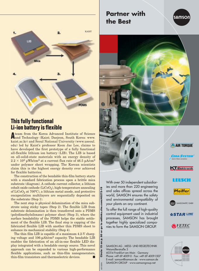
This fully functional Li-ion battery is flexible
A team from the Korea Advanced Institute of Science
and Technology (Kaist; Daejeon, South Korea: www.
kaist.ac.kr) and Seoul National University (www.useoul.
edu) led by Kaist’s professor Keon Jae Lee, claims to
have developed the first prototype of a fully functional
all-flexible lithium ion battery (LIB). The LIB is based
on all-solid-state materials with an energy density of
2.2 103 µWh/cm3 at a current flux rate of 46.5 µA/cm2
under polymer sheet wrapping. The Korean scientists
claim this is the highest energy density ever achieved
for flexible batteries.
The construction of the bendable thin-film battery starts
with a standard fabrication process upon a brittle mica
substrate (diagram). A cathode current collector, a lithium
cobalt oxide cathode (LiCoO2), high-temperature annealing
of LiCoO2 at 700ºC), a lithium metal anode, and protective
encapsulation multilayers are sequentially deposited on
the substrate (Step 1).
The next step is physical delamination of the mica sub-
strate using sticky tapes (Step 2). The flexible LIB from
substrate delamination is then transferred onto a PDMS
(polydimethylsiloxane) polymer sheet (Step 3), where the
surface bondability of the PDMS helps the stable settle-
ment of the flexible LIB. The final step is capping of the
fabricated flexible LIB with another thin PDMS sheet to
enhance its mechanical stability (Step 4).
The thin film LIB is capable of a maximum 4.2-V charg-
ing voltage and 106-µAh/cm2 capacity. The bendable LIB
enables the fabrication of an all-in-one flexible LED dis-
play integrated with a bendable energy source. This novel
approach can be expanded to various high-performance
flexible applications, such as thin-film nanogenerators,
thin-film transistors and thermoelectric devices. ■
A01
120
EN
Partner with
the Best
With over 50 independent subsidiar-ies and more than 220 engineering and sales offi ces spread across the world, SAMSON ensures the safety and environmental compatibility of your plants on any continent.
To offer the full range of high-quality control equipment used in industrial processes, SAMSON has brought together highly specialized compa-nies to form the SAMSON GROUP.
SAMSON AG · MESS- UND REGELTECHNIK Weismüllerstraße 360314 Frankfurt am Main · GermanyPhone: +49 69 4009-0 · Fax: +49 69 4009-1507 E-mail: [email protected] · www.samson.deSAMSON GROUP · www.samsongroup.net
Cir
cle
19
on
p.
60
or
go
to
ad
lin
ks.c
he
.co
m/4
02
72
-19
KAIST

16 CHEMICAL ENGINEERING WWW.CHE.COM OCTOBER 2012
NewsbriefsNewsbriefs
STB SEEKS RATE PROTECTION
FOR CAPTIVE RAIL SHIPPERS
The U.S. Surface Transportation Board (STB; Washington, D.C.; www.stb.dot.gov) announced two initiatives to explore
ways to further protect captive shippers — those having no practical alternative carrier for transporting their goods — from unreasonable rail rates. First, the STB proposed to reform its rules on how it resolves rate disputes to ensure that all cap-tive rail shippers have a meaningful way to challenge rates. Second, the STB is considering a proposal submitted by the National Industrial Transportation League (NITL) to increase rail-to-rail competition.
The centerpiece of the STB’s rate-rules proposal removes the limitation on relief for cases brought under the Simplified Stand-Alone Cost (SAC) alternative. “Our goal is to encourage shippers to use a simplified alternative to a Full-[Stand Alone Cost] analysis that is economically sound, yet provides a less complicated and less expensive way to challenge freight rates by discarding the requirement that shippers design a hypo-thetical railroad to judge a railroad’s real-world rates,” the STB wrote in a recently issued decision.
Captive shippers have long stated that they do not bring rate disputes to the STB because of the high litigation costs associ-ated with the Board’s complex Stand Alone Cost test, tradition-ally used to resolve major rate cases. To provide rail customers with a lower-cost, expedited alternative to this test, STB sim-plified evidentiary procedures, but because the methods used are less precise than those used in full SAC cases, the Board capped the amount of relief available under them. ❏
The Society of Chemical
Manufacturers and Affili-
ates (SOCMA; Washington,
D.C.; www.socma.com) testi-
fied before Congress last
month that poor implemen-
tation of the nation’s chemi-
cal security regulations has
created burdens on small
chemical companies.
Testifying on behalf of
SOCMA before the House
Subcommittee on Environ-
ment and the Economy,
Matthew Leary, corporate
EHS&S manager for Pilot
Chemical Co. (Cincinnati,
Ohio; www.pilotchemical.
com), discussed several is-
sues impeding compliance
with the Chemical Facility
Anti-Terrorism Standards
(CFATS), which are admin-
istered by the U.S. Dept. of
Homeland Security (DHS;
Washington, D.C.; www.
dhs.gov). Specifically, Leary
highlighted communications
issues with DHS and dif-
ficulties budgeting for com-
pliance. Leary said small
companies cannot afford to
spend on security in advance
unless they are certain it
will lead to compliance.
Also testifying was Timo-
thy Scott, chief security
officer at the Dow Chemical
Co., who also represented
the American Chemistry
Council (ACC; Washington,
D.C.; www.americanchem-
istry.com). Scott said that
while the CFATS concept is
sound, problems with imple-
menting the standards —
particularly in the area of
personnel surety — are real.
CFATS administration needs improve-ment, testimony argues
Royal Dutch Shell (The
Hague, the Netherlands;
www.shell.com) says it will
go ahead with the first
carbon capture and storage
(CCS) project for an oil-
sands operation in Canada.
The project will be built on
behalf of the Athabasca Oil
Sands Project joint-venture
owners (Shell, Chevron and
Marathon Oil) with support
from the governments of
Canada and Alberta.
The Athabasca Oil Sands
project produces bitumen,
which is piped to Shell’s
Scotford Upgrader near
Edmonton. Starting in late
2015, the project will cap-
ture and store, deep under-
ground, more than 1 mil-
lion metric tons a year of
CO2 produced in bitumen
processing. The project is
the world’s first commer-
cial-scale CCS project to
tackle carbon emissions in
the oil sands, and the first
CCS project in which Shell
will hold majority owner-
ship and act as designer,
builder and operator. It will
also form the core of Shell’s
CCS research program and
help develop Shell’s CO2
capture technology.
The CO2 will be trans-
ported through an 80-km
underground pipeline to
a storage site north of the
Scotford site. Here, the CO2
will be injected more than
2,000 m underground into
a porous rock formation
called the Basal Cambrian
Sands. Sophisticated moni-
toring technologies will
ensure the CO2 is perma-
nently stored.
ECHA seeks public consultation on substances of high concern
The European Chemicals
Agency (ECHA; Helsinki;
Finland; echa.europa.eu)
has opended a public com-
ment period on 54 poten-
tially harmful substances,
including 44 that are
proposed to be identified
as substances of very high
concern (SVHCs) because
of their classifications as
carcinogenic, mutagenic
or toxic for reproduction
(CMR). The list of sub-
stances proposed for identi-
fication as SVHCs include
four fluorodecanoic acid
compounds, several phtha-
lates and lead compounds,
as well as diazene-1,2 di-
carboxamide, methoxy ace-
tic acid and N,N-dimethyl
formamide.
The European Commis-
sion has requested ECHA to
prepare Annex XV dossiers
for 37 of the substances
on its behalf, and other
countries have put forward
proposals for the other 17
proposed substances.
Comments can be posted
on the ECHA website until
October 18, 2012. The
Member State Committee
will take comments into ac-
count when seeking agree-
ment on the identification
of all proposed substances
as SVHCs.
ECHA is also seeking
information on the uses of
the substances. This would
include data on tonnages
per use and exposures or re-
leases resulting from these
uses. Information on safer
alternatives and techniques,
and supply-chain structure,
are also welcome. ■
Shell to construct world’s first oil sands CCS project

Increasing production of natural gas from hydraulic fracturing of shale deposits has fundamentally altered the landscape of chemi-
cal production in North America. The higher margins on steam-cracking eth-ane to produce ethylene have resulted in significant feedstock shifts in the U.S. over the past two years. Numer-ous chemical producers are expanding ethylene capacity to take advantage of the increased availability of ethane from natural gas. The shift toward using more ethane as a feedstock for ethylene is generating a number of ripple effects for other chemicals, in-cluding tightness in the propylene and butadiene markets. Meanwhile, as manufacturers in energy-intensive industries take advantage of lower en-ergy costs offered by shale gas, other companies continue the pursuit of an alternative route to ethylene using methane as the feedstock.
Higher shale-gas production has re-sulted in a significant and longterm change in the relationship between petroleum and natural gas prices, ex-plains Russell Heinen, director of IHS Chemicals (Englewood, Colo.; www.ihs.com). “This change in price relation-ships has kept prices for ethane low relative to naptha, which is still the dominant feedstock for ethylene pro-ducers worldwide,” he says (Figure 2). IHS is preparing a report, “The Game Has Changed: The Influence of Shale Development on the Global Chemical Industry,” to be released this month.
Shale deposits vary greatly in the composition of natural gas. Some areas contain virtually no natural gas liquids (NGLs; ethane, propane
and butane), and some are very “wet,” containing from a few percent up to even 20% NGLs. Parts of the Marcel-lus shale in the eastern U.S. are very wet, for example, notes Heinen, while the Eagle Ford and Barnett shales in Texas produce dryer gas (more meth-ane with less NGLs).
Ethane to ethyleneDriven by a wide range of derivatives, ethylene is the most-produced organic chemical in the world, with volumes expected to top 160 million tons in 2012, accounting for $150 billion in sales. Major polymers and chemicals made from ethylene include: low-den-sity polyethylene (LDPE); linear low-density polyethylene (LLPDE); and high-density polyethylene (HDPE); as well as polyvinyl chloride; ethyl-ene oxide; ethanol; ethylene propylene diene monomer (EPDM) and others. End-use markets include wire and cable insulation; consumer, industrial and agricultural packaging; woven
fabrics; coverings, pipes, conduits and assorted construction materials; drums, bottles and other containers; and antifreeze, solvents and coatings.
According to an analysis by the American Chemistry Council (ACC; Washington, D.C.; www.american-chemistry.com), the additional output of chemical derivatives generated by a 25% increase in ethane production would translate to $18.3 billion worth of bulk petrochemicals and organic intermediates, as well as $13.1 billion worth of plastics resins and $1.0 bil-lion of rubber.
New capacityA major driver of the increasing eth-ane-cracking capacity is the ratio be-tween crude oil and natural gas prices, which has been generally increasing since January 2009, and is at histori-cally high levels (40 to 1 or higher).
“To date, most new capacity for eth-ylene has come through retrofits and expansions, but the bulk of new capac-
CHEMICAL ENGINEERING WWW.CHE.COM OCTOBER 2012 17
Newsfront
Growth in North American ethane cracking
has wider effects for the CPI, while some companies
look to harness methane for ethylene
FIGURE 1. Siluria Technolo-gies has developed a catalyst
for the oxidative coupling of methane (OCM), potentially
opening the door to commer-cial-scale ethylene directly from methane in one step
TABLE 1. NORTH AMERICAN ETHYLENE CAPACITY GROWTH
Company Location Capacity, thou-sands of ton/yr
Start up year
Dow Chemical Freeport, Texas 1,906 2014–2017
Ineos Lake Charles, La. 1,361 2018
CP Chem Baytown, Tex. 1,134 2016–2017
Braskem/Idesa Coatzacoalcos, Mexico 998 2015
Shell Chemical Pennsylvania 907 2016+
Formosa Plastics Point Comfort, Tex. 799 2015
LyondellBasell Texas and Illinois 658 2012–2014
Dow Chemical Hahnville, La. 363 2012 (4th Q)
Williams Lake Charles, La. 272 2013 (3rd Q)
Westlake Chemical Lake Charles, La. 104 2012
Ineos Chocolate Bayou, Tex. 104 2013
Total 8,607
SHALE GAS USHERS IN ETHYLENE FEED SHIFTS
Siluria Technologies
Source: IHS Chemical
18 CHEMICAL ENGINEERING WWW.CHE.COM OCTOBER 2012
Newsfront
ity from newly built plants will
start to come online in 2016 and
2017,” says IHS’s Heinen.
Since 2010, 450,000 ton/yr
of ethylene production capac-
ity have been added through retrofits,
upgrades and expansions in the U.S.,
and producers have announced over 5
million ton/yr of new ethylene capacity
that are scheduled to come online by
2018 (Table 1). And since the additional
ethane potential would allow about 11
million ton/yr of ethylene, there is still
plenty of room for new capacity to be
added to balance potential supply with
demands. That means more ethylene
capacity is likely, Heinen says.
Industry faces several challenges
associated with the added capacity,
Heinen notes, including the ability to
bring capacity online without delay,
and the ability of ethylene producers
to work out the supply logistics of han-
dling nearly 300–400 thousand bbl/d
of new ethane by 2020. Also, Heinen
points out that other potential chal-
lenges are that U.S. ethylene supply
increases could impact pricing; and
environmental concerns related to
shale-gas drilling could spur legisla-
tion restricting hydraulic fracturing.
Another challenge for ethylene
producers is that some of the newer
crackers are ethane-specific, giving up
feedstock flexibility to focus on eth-
ane cracking, so future growth might
be hindered if economics change and
flexibility is needed.
On-purpose propyleneThe shift to lighter feedstocks for eth-
ylene (using more ethane) is beginning
to have ripple effects that are likely
to grow going forward. When steam-
cracking naptha or gas oil, propylene
and other chemicals are formed as
co-products alongside ethylene; but
when ethane is the feedstock, ethyl-
ene is the primary product, with mini-
mal co-products formed. So the shift to
ethane as a feedstock has resulted in
tighter supplies of three- and four-car-
bon chemicals, particularly propylene
and butadiene, which is likely to raise
prices for those chemicals, says IHS’
Heinan (Figure 3).
Tightness in propylene supply has
improved the cost-competitiveness
of on-purpose propylene production,
notes Felipe Tavares, director of In-
tratec (Houston; www.intratec.com).
Several on-purpose propylene produc-
tion alternatives exist, including those
using NGLs — propane dehydrogena-
tion (PDH) and propylene production
via metathesis chemistry.
PDH is a catalytic process in which
the hydrogen byproduct can be used
as fuel for the reaction. Metathesis is
a catalyzed reaction between butenes
and ethylene where double bonds are
reformed. Propylene technology is
among the first topics covered in In-
tratec’s “Knowledge Base,” an online
encyclopedia of chemical technology
and economics. The tool can be found
at: base.intratech.us.
Capacity growth for propylene from
PDH is poised to grow significantly.
The Dow Chemical Co. (Midland,
Mich.; www.dow.com) has announced
plans for a 750,000 ton/yr PDH plant
in Freeport, Tex., using technology
from UOP LLC (Des Plaines, Ill.; www.
uop.com). Formosa Plastics and Enter-
prise Products Partners LP (Houston;
www.enterpriseproducts.com) has also
announced plans for PDH facilities on
the U.S. Gulf Coast.
Lummus Technology / CB&I Co. (The
Hague, the Netherlands; www.cbi.com)
is currently the only licensor to offer
an olefin metathesis process, known
as olefin conversion technology (OCT),
to make propylene from ethylene and
butenes. In cases where only ethylene
is readily available, Intratec’s Tavares
says the metathesis process could be
combined with a dimerization plant,
which converts ethylene to 2-butene.
Utilizing methaneWhile methane from natural gas will
continue to play a prominent role as
a cleaner-burning alternative to coal
for power generation, its abundance
(~10 times more than ethane in natu-
ral gas) and price (about half the price
of ethane) is spurring a wide-ranging
effort to utilize methane directly as
a feedstock for ethylene and other
chemicals, rather than burning it as
fuel (Figure 1). Since so much natu-
ral gas is available, new demands for
methane are needed, says Rahul Iyer,
senior director of corporate develop-
ment at Siluria Technologies (San
Francisco, Calif.; www.siluria.com).
Dallas Kachan (Kachan & Co.; San
Francisco, Calif.; www.kachan.com),
an analyst and consultant in the clean
technology industry, points out that
the energy and capital intensity re-
quired for steam cracking of ethane
provides an incentive to make ethyl-
ene in alternative ways. Commercially
viable ways to make ethylene directly
from methane, if successful, could be
a watershed moment for the chemical
and petroleum industries, Kachan re-
cently wrote in a blog post.
Significant activity is ongoing to-
ward commercialization of methane-
to-ethylene technologies, with many
startups — some announced and some
“undercover” — working on various
technologies, while university and
government laboratories also attack
the problem, according to research by
Kachan & Co. The major integrated
petroleum companies, including Chev-
ron, ExxonMobil, Shell and BP hold a
surprisingly wide-ranging portfolio of
patents for methane-to-ethylene tech-
nologies, and several large chemical
companies also hold some intellectual
property in this area (BASF, Lubrizol,
SABIC, GE, Honeywell and others),
Kachan research found.
Methane-to-ethylene technologies
are being considered for use in remote
areas where natural gas associated
with crude oil drilling is flared, or re-
mote gasfields where no pipelines exist
and transporting the gas is difficult.
Smaller-scale gas-to-liquids (GTL)
technologies are needed for areas
with “stranded gas,” says Sulkhan
Davitadze, an investment director at
Bright Capital (Moscow, Russia; www.
bright-capital.com), a venture capital
firm with a portfolio of companies in
the energy and chemicals areas.
A number of smaller-scale GTL
processes exist, some using a Fischer-
Tropsch (F-T)-based approach and
some taking different paths. All are
WIDER SHALE GAS EFFECTS
A host of additional effects of the shale gas boom is generating profound changes across the chemical industry and beyond, including rising methanol and ammonia production capacity in
the U.S., says ACC economist Martha Gilchrist-Moore, who will be speaking about the implica-tions of the shale gas boom at ChemInnovations 2012, along with IHS’ Heinen (see p. 24D-1).
The availability of shale gas will also have a profound effect on manufacturing more generally. Energy-intensive sectors like iron and steel, plastics, glass, rubber, aluminum, fabricated metals and papers all stand to gain from inexpensive shale gas, she says. Also, combined heat and power cogeneration plants are even more economically attractive, she notes.
CHEMICAL ENGINEERING WWW.CHE.COM OCTOBER 2012 19
potentially useful, but it’s not clear yet
what the economics will turn out to be,
Davitadze remarks.
SynFuels International (Dallas,
Tex.; www.synfuels.com) is looking
to make higher-value chemicals from
methane without using Fischer-Trop-
sch chemisty. SynFuels has designed
a non-catalytic, water-jacketed, fixed-
bed reactor that pyrolyzes methane,
generating a mixture of gases com-
posed mostly of acetylene, as well as
some carbon monoxide and hydrogen
(Figure 4). The gas mix is fed into an
absorber that separates the acetylene
from the other gases.
Acetylene is then hydrogenated,
while still absorbed, using some of the
hydrogen produced in the initial pyrol-
ysis step. A specially designed hydro-
genation catalyst that tolerates high
levels of carbon monoxide is used. The
process, based on technology originally
conceived at Texas A&M University
(College Station, Tex.; www.tamu.edu),
is capable of producing polymer-grade
ethylene in 96% yields from acetylene.
The ethylene can also be taken fur-
ther to gasoline blendstock (a mix of
C4 to C12 hydrocarbons) through an
oligomerization technique also devel-
oped by SynFuels. The company oper-
ates a fully integrated GTL demon-
stration plant in Bryan, Tex., capable
of processing 50,000 ft3/day of natural
gas into gasoline blendstock.
Siluria Technologies is trying to
commercialize a single-step methane-
to-ethylene process. The company just
announced plans to build a demon-
stration facility for its process, which
is based on oxidative coupling of meth-
ane (OCM) chemistry. According to Si-
luria CEO Alex Tchachenko, construc-
tion on the demonstration plant will
begin in 2013, and it will be capable
of producing hundreds of thousands
of gallons per year. Siluria’s technol-
ogy depends on a carefully made cata-
lyst that promotes ethylene formation
over non-selective oxidation reactions
(Chem. Eng., December 2010, p. 12).
Siluria’s technology is attractive
because it’s a one-step process that is
capital efficient as well as energy ef-
ficient, Davitadze comments.
Using a genetically engineered bac-
teriophage (bacteria-infecting virus) as
a template for material growth, Siluria
scientists developed a catalyst mate-
rial that has a unique crystal structure
and surface morphology. The structure
gives rise to catalyst active sites that
can select ethylene formation over
non-specific oxidation of methane. The
catalyst is a doped metal oxide of tran-
sition metals that is designed for com-
patability with existing petrochemical-
industry infrastructure.
The Siluria technology has a num-
ber of advantages over F-T approaches
because it can be accomplished in
one step, at lower temperatures, and
works well with existing hydrocarbon
processing equipment. Siluria’s OCM
technology is an exothermic reaction,
so it requires less energy input, and
the heat given off by the process can
be harvested to drive the process. “We
believe we are the first to develop a
commercially viable, scalable process
for OCM,” Tchachenko says.
Siluria’s catalyst-discovery engine
has the potential to develop other cata-
lysts to make different products. Silu-
ria’s Iyer says the company will be able
to achieve the economics enjoyed by a
world-scale plant in a much smaller
facility, so significant capital-expense
savings are possible.
OCM is also of interest to the Pol-
ish national research laboratory Fer-
tilizer Research Institute (Pulawy,
Poland; www.ins.pulawy.pl). Scien-
tists there have built a pilot plant for
a methane-to-ethylene facility based
on OCM. Also, UOP has reportedly
proved, in the laboratory, a one-step
process for directly converting meth-
ane to ethylene. The company is look-
ing for partners to build a pilot plant
for the process. UOP says its technol-
ogy could potentially save 40% of the
cost of ethane-based ethylene. ■ Scott Jenkins
Editor’s note: An expanded version of this arti-cle, with additional background information and graphics can be found at www.che.com.
U.S. ethylene production by feedstock
0
5,000
10,000
15,000
20,000
25,000
30,000
1990
1991
1992
1993
1994
1995
1996
1997
1998
1999
20
00
20
01
20
02
20
03
20
04
20
05
20
06
20
07
20
08
20
09
2010
2011
2012
Heavier
Butane
Propane
Ethane
Metr
ic t
on
s
Steam cracker propylene and butadiene production
Ratio to ethylene33 8
8
7
7
6
6
5
5
4
31
29
27
25
23
21
19
17
15
1990
1991
1992
1993
1994
1995
1996
1997
1998
1999
20
00
20
01
20
02
20
03
20
04
20
05
20
06
20
07
20
08
20
09
2010
2011
2012
Pro
pyle
ne/e
thyle
ne
, %
Bu
tad
ien
e/e
thyle
ne
, %
Propylene/ethylene
Butadiene/ethylene
FIGURE 2. Shale gas has pushed natural gas and ethane production higher. Fore-casts indicate the production will rise further
FIGURE 3. Propylene and butadiene production (shown as a ratio to ethylene) have fallen as a result of the shift to lighter feedstocks by ethylene producers
FIGURE 4. SynFuels International uses methane in pyrolysis reactors to generate acetylene, which is then hydrogenated to ethylene
Source: IHS Chemical
Source: IHS Chemical
Syn
Fu
els In
tern
atio
na
l
20 CHEMICAL ENGINEERING WWW.CHE.COM OCTOBER 2012
Newsfront
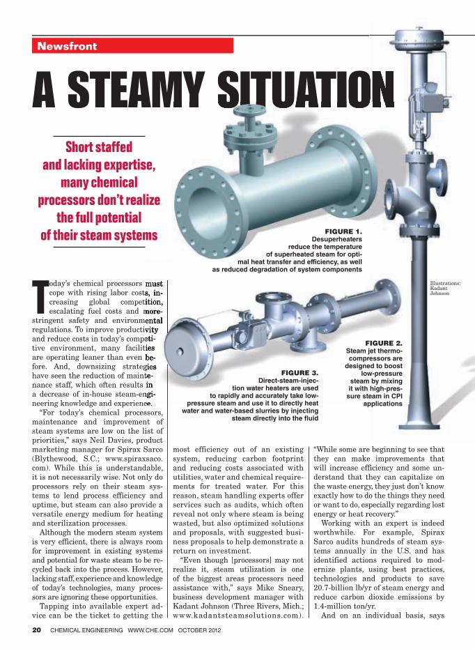
Today’s chemical processors must
cope with rising labor costs, in-
creasing global competition,
escalating fuel costs and more-
stringent safety and environmental
regulations. To improve productivity
and reduce costs in today’s competi-
tive environment, many facilities
are operating leaner than even be-
fore. And, downsizing strategies
have seen the reduction of mainte-
nance staff, which often results in
a decrease of in-house steam-engi-
neering knowledge and experience.
“For today’s chemical processors,
maintenance and improvement of
steam systems are low on the list of
priorities,” says Neil Davies, product
marketing manager for Spirax Sarco
(Blythewood, S.C.; www.spiraxsaco.
com). While this is understandable,
it is not necessarily wise. Not only do
processors rely on their steam sys-
tems to lend process efficiency and
uptime, but steam can also provide a
versatile energy medium for heating
and sterilization processes.
Although the modern steam system
is very efficient, there is always room
for improvement in existing systems
and potential for waste steam to be re-
cycled back into the process. However,
lacking staff, experience and knowledge
of today’s technologies, many proces-
sors are ignoring these opportunities.
Tapping into available expert ad-
vice can be the ticket to getting the
most efficiency out of an existing
system, reducing carbon footprint
and reducing costs associated with
utilities, water and chemical require-
ments for treated water. For this
reason, steam handling experts offer
services such as audits, which often
reveal not only where steam is being
wasted, but also optimized solutions
and proposals, with suggested busi-
ness proposals to help demonstrate a
return on investment.
“Even though [processors] may not
realize it, steam utilization is one
of the biggest areas processors need
assistance with,” says Mike Sneary,
business development manager with
Kadant Johnson (Three Rivers, Mich.;
www.kadantsteamsolutions.com).
“While some are beginning to see that
they can make improvements that
will increase efficiency and some un-
derstand that they can capitalize on
the waste energy, they just don’t know
exactly how to do the things they need
or want to do, especially regarding lost
energy or heat recovery.”
Working with an expert is indeed
worthwhile. For example, Spirax
Sarco audits hundreds of steam sys-
tems annually in the U.S. and has
identified actions required to mod-
ernize plants, using best practices,
technologies and products to save
20.7-billion lb/yr of steam energy and
reduce carbon dioxide emissions by
1.4-million ton/yr.
And on an individual basis, says
Newsfront
Short staffed
and lacking expertise,
many chemical
processors don’t realize
the full potential
of their steam systems
A STEAMY SITUATION
FIGURE 3. Direct-steam-injec-
tion water heaters are used to rapidly and accurately take low-
pressure steam and use it to directly heat water and water-based slurries by injecting
steam directly into the � uid
FIGURE 1. Desuperheaters
reduce the temperature of superheated steam for opti-
mal heat transfer and efficiency, as well as reduced degradation of system components
FIGURE 2.
Steam jet thermo-compressors are
designed to boost low-pressure
steam by mixing it with high-pres-
sure steam in CPI applications
Illustrations: Kadant Johnson

CHEMICAL ENGINEERING WWW.CHE.COM OCTOBER 2012 21
Sneary, steam system improve-
ments for many facilities can identify
50,000 to 100,000 lb of lost steam en-
ergy, which, if stopped, can result in
a tremendous savings. But, he says,
to reap the savings, processors need
the assistance of an expert. “Often,
folks in the facility just look at the
wasted steam and think ‘this is the
way it’s always been,’ or they may
not be aware of new equipment that
could benefit their steam system.
But, people from the outside can see
the wasted energy, figure out ways to
recover it and use it elsewhere and
point out how modern equipment can
assist with the process. So, it’s really
worth it to tap into this expertise.”
The first step is to find a firm that has
the experience to provide a range of ser-
vices from onsite auditing to steam trap
surveys to the ability to recommend and
provide turnkey installations, as well
as the knowledge and understanding to
provide financial information that will
justify any improvements.
From there, an audit, including a
steam trap survey that reveals the
condition of the steam traps and
which ones have failed, closed or gone
cold, is normally conducted. Follow-
ing this audit, recommendations are
made to repair or replace failed steam
traps first, then cold steam traps and
finally closed steam traps. And finan-
cial justification is often offered to
increase the chances of investment in
the system.
Once the expert fully understands
the complete process that takes place
in the facility, and if the processor
chooses, the expert can then make
recommendations on how to modify
the system in an effort to move some
of the wasted energy into another
process. “The process is all about un-
derstanding their facility and their
process and then trying to figure out a
way to save them money,” says Sneary.
“And often we save them money by
turning wasted steam into usable
steam, using a wealth of equipment
for this purpose that they may not yet
know exists.”
He says that currently products are
available from many steam system
providers, such as thermocompres-
sors, desuperheaters (Figure 1) and
water-jet heaters, to make heat recov-
ery easier and more affordable than
ever before.
For example, steam-jet thermo-
compressors (Figure 2) are designed
to boost low-pressure steam by mix-
ing it with high-pressure steam
in the chemical process industries
(CPI) in applications such as drying,
filtration, distillation, absorption,
mixing, vacuum packaging, freeze
drying, flash cooling, deaerating and
dehydrating.
Desuperheaters are intended to re-
duce the temperature of superheated
steam for optimal heat transfer and
efficiency, as well as reduced degra-
dation of system components. The ef-
ficient geometry allows for direct in-
stallation into the steam pipeline with
flanged connections.
And, direct-steam-injection water
heaters (Figure 3) are used to rap-
idly and accurately take low-pressure
steam and use it to directly heat water
and water-based slurries by injecting
steam directly into the fluid. They are
used in CPI applications including
boiler feedwater preheating, fibrous
slurries such as pulp stock and bio-
mass pre-treatment, sanitization and
tank cleaning and anaerobic treat-
ment of organic waste.
While just a simple steam-trap
survey can yield hundreds of thou-
sands of dollars a year in lost steam
savings and energy reductions, it
may provide the impetus to further
investigate the possibility for heat
recovery projects that could boost
these savings even more. ■
STEAM CYCLE SOLUTION CAN OPTIMIZE PERFORMANCE
FOR POWER PLANT BOILERS
Steam plant operators are looking for control solutions that will help them optimize boiler efficiency by reducing fuel consumption while reducing emissions, according to Bill
Pezalla, global energy industry manager for GE Intelligent Plat-forms (Charlottesville, Va.; www.ge.com). High-performance plants under 300 MW can meet these needs with control solu-tions based on expertise in steam-cycle generation management, which can help reduce fuel usage while allowing boilers to run safely and efficiently.
For example, GE’s Steam Cycle control solution is based on a flexible and scalable DCS, Proficy Process Systems, along with pre-packaged advanced combustion-control algorithms and strat-egies for fossil and biomass fuels to achieve operational benefits and mitigate risk.
These advanced combustion-control algorithms and strategies op-timize the combustion process to reduce fuel usage 3 to 5%, which allows them to better meet stringent emissions regulations. In addi-tion, the technologies keep equipment safe and protected by main-taining the water level in the boiler to prevent damage. Because the control algorithms and strategies are pre-engineered, they are capable of reducing system implementation time by 50 to 80%.
“Power plants are running longer with shorter maintenance out-
ages,” says Pezalla. “The advantage of this control system is that it is an open system that works with any type of boiler and can be implemented during a short maintenance outage leading to the realization of rapid fuel and water savings. These efficiencies need to be factored into the total cost of ownership when purchas-ing control systems.”
“Adding boiler and turbine auxiliary-equipment control strategies provides a more comprehensive solution,” notes Craig Thorsland, steam-cycle solutions leader for GE Intelligent Platforms. “Opti-mally, the overall control solution reduces the need for operator intervention. This stabilizes steam production and frees operators to focus on plant operations. With stable and consistent opera-tions, the thermal stresses on the boiler and turbine are reduced, extending their lifecycles.”
Safety is a concern and the Steam Cycle solution addresses that concern with drum-level control strategies that allow water levels to be properly maintained to avoid boiler failure. “It is critical to keep the water level in the boiler at the proper level,” explains Thorsland. “If it falls too low, the boiler can be damaged, or worse yet, fail with problematic consequences. Control strategies can compensate for varying loads and the resulting increases or de-creases in water level.” ❏

22 CHEMICAL ENGINEERING WWW.CHE.COM OCTOBER 2012
Newsfront
Free float trap for facilities with corrosive environmentsThis free float trap (photo) is suitable
for the food industry, plants with cor-
rosive environments and petroleum
refineries and petrochemical plants
where steel materials are required.
The J3X provides corrosion resistance
through the use of high quality CF8
stainless-steel material. It delivers
continuous, smooth, low-velocity con-
densate discharge as process loads
vary. The float has an unmatched
sealing performance and is designed
for severe service operations. Rated
for 1,740 psig hydraulic shock, the
free float provides waterhammer re-
sistance. The product also offers the
possibility for inline repairs and a
thermostatic air vent that automati-
cally vents air for easier startups. —
TLV Corp., Charlotte, N.C.
www.tlv.com
Steam generators and fluid heaters offered in many sizesOffered in 18 sizes ranging from 25 to
1,000 boiler hp and 862 to 34,500 lb/h
of steam, these controlled-flow water-
tube boiler units are built to appropri-
ate national and local standards. Units
are designed to burn natural gas, pro-
pane, light oil and heavy oil, as well as
a combination of these fuels and are
available with steam design pressures
up to 3,000 psig. A Superheat version
of the E-Series product, which provides
superheated steam is available in a va-
riety of sizes for a range of steam pres-
sures and temperatures. — Clayton
Industries, City of Industry, Calif.
www.claytonindustries.com
Thermostatic steam trap is unaffected by waterhammerThe Gestra MK 36/51 thermostatic
steam trap with a corrosion-resistant
membrane regulator (thermostatic
capsule) is unaffected by water ham-
mer. An integral strainer and stan-
dard capsule for discharge are avail-
able with virtually no backing up. The
traps are suitable for draining satu-
rated steam lines and steam tracers
and can also be used for air venting.
They can be installed in any position,
but if installed in horizontal pipes, it
is important to make sure the cover is
on top. — Flowserve, Irving, Tex.
www.gestra.com
This steam trap resists corrosion from clean and pure steamThe BTS7.1 stainless-steel clean steam
trap is constructed to withstand cor-
rosion from clean and pure steam ap-
plications. The unit is pressure rated
to ASME standards and is designed to
remove condensate from clean steam
systems with minimal backup, mak-
ing it suitable for the pharmaceutical,
biotechnology and food-and-beverage
industries. The self-draining trap
operates close to steam saturation
temperatures, reducing condensate
backup and effectively venting air, en-
suring full sterilization. The smooth
surfaces provide a free-draining
surface, reducing the risk of bacte-
rial growth and product blockage. —
Spirax Sarco, Inc., Blythewood, S.C.
www.spiraxsarco.com
A disc trap that performs with low-cost maintenancePart of the PowerDyne thermody-
namic steam trap family, the stainless
steel P46SRN has a replaceable mod-
ule that allows the unit to be serviced
without removing the trap body from
installation. With the same capacity,
pressure and temperature specifica-
tions as the cast steel version, the
P46SRN has a corrosion-resistant
stainless-steel body. Designed for ef-
ficient performance, low-cost mainte-
nance and durability, the product is a
suitable for steam mains, tracers and
coils. — TLV Corp., Charlotte, N.C.
www.tlv.com ■Joy LePree
STEAM-HANDLING
PRODUCTS
TLV
RECEIVE
FULL ACCESS
to ALL of Chemical Engineering’s
Facts at Your Fingertips articles in
one convenient location.
EACH INFORMATION PACKED PDF
article includes graphs, charts, tables,
equations and columns on the full
chemical engineering processes you
deal with on a daily basis. This is the
tool you will come to rely on, referring
back to the information again and
again with just the click of a mouse.
Facts at Your Fingertips Topics Include:
Conservation Economics: Carbon
Pricing Impacts
Distillation Tray Design
Burner Operating Characteristics
Measurement Guide for
Replacement Seals
Steam Tracer Lines and Traps
Positive Displacement Pumps
Low-Pressure Measurement for
Control Valves
Creating Installed Gain Graphs
Aboveground and Underground
Storage Tanks
Chemical Resistance of
Thermoplastics
Heat Transfer: System Design II
Adsorption
Flowmeter Selection
Specialty Metals
Plus much, much more…
Receive full access today by visiting
www.omeda.com/cbm/facts
17872
Receive full access today by visitinghttp://store.che.com/product/facts

Manufacturer’s warranty period
extended to two years
This manufacturer of gas detection
and environmental monitoring sys-
tems has extended its warranty period
to two years, providing additional cov-
erage for all of its equipment. The com-
pany also offers a service contract spe-
cifically tailored to requirements that
cover the maintenance of its products
(photo). When customers call for prod-
uct support, they speak directly to an
engineer, not a call center. — Trolex
Ltd., Stockport, Cheshire, U.K.
www.trolex.com
PID detects VOCs and up to
four more hazards
Rugged and durable, the GasAlertMi-
cro 5 PID (photo) measures for photo-
ionization detectable (PID) VOCs
(volatile organic compounds), while si-
multaneously monitoring and display-
ing up to four additional atmospheric
hazards, including oxygen, combus-
tible gases and a range of toxic gases.
The PID sensor adds photo-ionization
detection capabilities. Compact and
lightweight, with a concussion-proof,
waterproof IP66/67-rated boot, it is
well suited for harsh industrial envi-
ronments. The portable gas detector
provides multi-language support in
English, French, German, Spanish
and Portuguese and offers visual, au-
dible and vibrating alarms. — Honey-
well Process Solutions, Houston
www.honeywell.com
Detector now approved
for underground mining
The lightweight and highly configu-
rable Ventis MX4 (photo) is capable
of detecting from one to four gases,
including oxygen (O2), methane (CH4)
and any two of the following toxic
gases: carbon monoxide (CO), hydrogen
sulfide (H2S), nitrogen dioxide (NO2)
and sulfur dioxide (SO2). The Ventis
can be configured with CH4, CO, and
O2 sensors for many everyday mining
applications, or it can be configured
with CH4, CO, O2 and NO2 sensors,
making it ideal for mines using diesel
equipment. In fact, the Ventis MX4 has
recently received MSHA approval for
underground mining. The Ventis with-
out pump has been certified by MSHA
under Title 30 CFR, Part 22 when used
with the standard or extended runtime
lithium-ion battery packs. The com-
pany anticipates that the Ventis with
pump will receive MSHA approval
later this year. — Industrial Scientific
Corp., Pittsburgh, Pa.
www.indsci.com/ventis
Measure thousands of gases
in the fi eld
The DX4040 (photo) is the second
generation of what is said to be the
world’s first truly portable FTIR (Fou-
rier transform infrared) spectroscopy
analyzer, a technology that brought
laboratory-grade gas analysis into the
field. Up to 25 gases can be displayed
simultaneously when operating the
DX4040 with a handheld PDA. How-
ever, the most important development
lies in the ability of the device to iden-
tify unknown gases in the field (at
the touch of one button) when using
a new version of the unit’s Calcmet
software on a Windows tablet. The
DX4040 is unique because it is able
to identify both organic and inorganic
compounds, while also storing sample
spectra for post-measurement analysis
using a chemical library of over 5,000
compounds. There are no sensors that
might need future replacement. No
sample preparation is required, and
calibration is simply a zero check with
nitrogen or air. — Gasmet Technolo-
gies Oy, Helsinki, Finland
www.gasmet.fi
O2 analyzer approved for hazard-
ous-area use in North America
XTP601 Oxygen Analyzer (photo, p. 24)
has attained CSA certification, making
it approved for use in hazardous areas
in the U.S. and Canada. The instru-
ment already carries certification from
ATEX and IEC Ex, and the addition of
CSA broadens its global coverage. The
XTP601 uses thermo-paramagnetic
measurement technology to make ac-
curate and stable measurements of ox-
ygen in background gases such as hy-
drogen, nitrogen and carbon dioxide. It
is capable of measuring oxygen ranges
from 0–1% up to 0–25%. Typical haz-
ardous applications include monitor-
ing of inerting or blanketing gases in
CHEMICAL ENGINEERING WWW.CHE.COM OCTOBER 2012 23 Note : For more information, circle the 3-digit number on p. 60, or use the website designation.
Honeywell Process Solutions
Trolex
Industrial Scientific
Gasmet Technologies
FOCUS ON
Gas Detection & Handling

Focus
24 CHEMICAL ENGINEERING WWW.CHE.COM OCTOBER 2012
petroleum refining, chemical and phar-
maceutical industries. The analyzer,
which is housed in a tough flame-proof
and explosion-proof housing, is avail-
able in three versions: a blind trans-
mitter; a unit with status LEDs or a
full-display unit. This last version has
a touch-screen interface, which allows
through-the-glass interaction, elimi-
nating the need to remove the analyzer
lid (except for service). All versions are
supplied with two 4–20-mA outputs,
two concentration alarms Modbus
RTU over RS485 protocol and applica-
tion software as standard. — Michell
Instruments, Ely, Cambridgeshire, U.K.
www.michell.com
Fixed gas detector is protected
against dust and water
The OLCT IR infrared fixed gas detec-
tor (photo) has been tested according
to IEC/EN 60529 and gets the IP67
protection degrees. As a result, the
OLCT IR is totally protected against
dust and against the effect of immer-
sion in up to 1 m of water, putting the
OLCT IR ahead of competitors’ prod-
ucts, says the manufacturer. With a
stainless-steel 316L enclosure, dual
source, four-beam technology, and
heated optics the OLCT IR is said to
be one of the most reliable infrared
(IR) gas detectors on the market. A
low-temperature version allows op-
eration down to –50°C for the harsh-
est industrial environment. The mean
time between failures (MTBF) and
the probability of failures on demand
(PDF) both calculated by INERIS are
respectively 28 years and 1,6 10–3
with a one-year interval test. — Old-
ham Gas, Pittsburgh, Pa.
www.oldhamgas.com
CO2 detector protects
against dangerous leaks
Offering reliable gas detection per-
formance with low maintenance, the
rugged Model IR700 Carbon Dioxide
Point Detector (photo) requires no
routine calibration and provides com-
plete control room status and control
capability for monitoring 0–5,000
ppm. The Model IR700 features a pre-
cision IR point-sensing element that
offers reliable protection against the
hazards of carbon-dioxide gas leaks.
While CO2 is nonflammable, exposure
to atmospheric concentrations above
5,000 ppm is considered unhealthy,
making careful monitoring crucial
at lower levels. The IR700 features a
true fail-to-safe design for dependable
gas detection performance, heated op-
tics to eliminate condensation, and a
dirty optics indicator informs the user
the device must be cleaned before the
lenses are entirely blocked, thereby
reducing downtime. The Model IR700
IR detector features microprocessor-
based technology to continuously
monitor CO2. It features multiple
communication outputs, a 4–20-mA
signal, proportional to 0–100% full-
scale, Modbus and HART. — General
Monitors, Lake Forest, Calif.
www.generalmonitors.com
Wireless communication im-
proves installation and trending
Said to be an industry first, ELDS
Version 1.2 Open Path Gas Detectors
(OPGDs) feature Integrated 2.4 GHz
Wireless Communications between the
ELDS Transmitters/Receivers and the
vendor’s installation and commission-
ing tools. The ELDS is easy to install,
with 2.4 GHz wireless alignment and
access to event logs, self check results,
and system diagnostics. This eliminates
hard-wired Class I Division I or II con-
nectors and cables, or area de-classifi-
cation for technician access to detectors
via open junction box terminals for com-
missioning. ELDS Version 1.2 Wireless
is particularly beneficial for OPGD sys-
tems installed high in the air or under
floor grates. Version 1.2 also features
expanded gas applications for high-
level H2S detection at 0–15,000 ppm in
FPSO Vent Gases, low-level ppm ammo-
nia OPGD, low-level ppm HF OPGD for
refinery alkylation processes, percent
LEL HVAC OPGD cross-duct methane
detection, and percent LEL cross-duct
continuous methane monitoring for
coal-bed combustion. — Senscient, Inc.,
League City, Tex.
www.senscient.com
Detect oxygen defi ciency with-
out high maintenance burdens
The 4501-03, Oxygen Deficiency Gas
Detector (photo) is a two-wire, loop-
powered gas detector that boasts lower
cost and easier installation and main-
tenance. This eliminates the need for
separate power runs and associated
power distribution and circuit protec-
tion for each device. Meanwhile, main-
tenance costs are low due to 4–20-mA,
two-wire loop-powered design, a six-
month calibration interval and the
ability to calibrate without declassify-
ing the area. — Sierra Monitor Corp.,
Milpitas, Calif.
www.sierramonitor.com ■Rebekkah Marshall
Michell Instruments
Oldham Gas General Monitors
Sierra Monitor
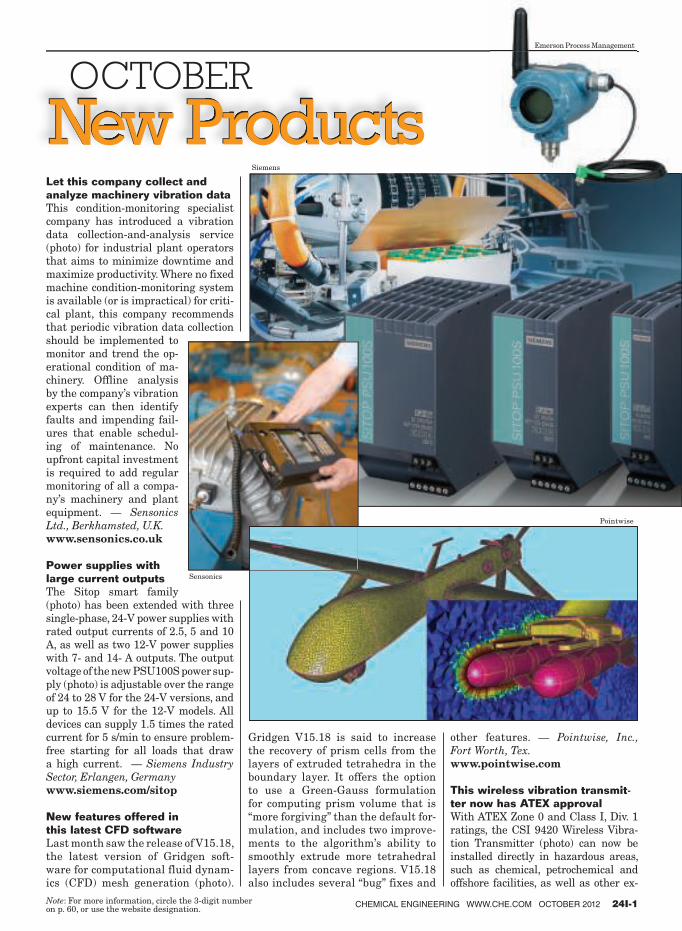
Let this company collect and
analyze machinery vibration data
This condition-monitoring specialist
company has introduced a vibration
data collection-and-analysis service
(photo) for industrial plant operators
that aims to minimize downtime and
maximize productivity. Where no fixed
machine condition-monitoring system
is available (or is impractical) for criti-
cal plant, this company recommends
that periodic vibration data collection
should be implemented to
monitor and trend the op-
erational condition of ma-
chinery. Offline analysis
by the company’s vibration
experts can then identify
faults and impending fail-
ures that enable schedul-
ing of maintenance. No
upfront capital investment
is required to add regular
monitoring of all a compa-
ny’s machinery and plant
equipment. — Sensonics
Ltd., Berkhamsted, U.K.
www.sensonics.co.uk
Power supplies with
large current outputs
The Sitop smart family
(photo) has been extended with three
single-phase, 24-V power supplies with
rated output currents of 2.5, 5 and 10
A, as well as two 12-V power supplies
with 7- and 14- A outputs. The output
voltage of the new PSU100S power sup-
ply (photo) is adjustable over the range
of 24 to 28 V for the 24-V versions, and
up to 15.5 V for the 12-V models. All
devices can supply 1.5 times the rated
current for 5 s/min to ensure problem-
free starting for all loads that draw
a high current. — Siemens Industry
Sector, Erlangen, Germany
www.siemens.com/sitop
New features offered in
this latest CFD software
Last month saw the release of V15.18,
the latest version of Gridgen soft-
ware for computational fluid dynam-
ics (CFD) mesh generation (photo).
Gridgen V15.18 is said to increase
the recovery of prism cells from the
layers of extruded tetrahedra in the
boundary layer. It offers the option
to use a Green-Gauss formulation
for computing prism volume that is
“more forgiving” than the default for-
mulation, and includes two improve-
ments to the algorithm’s ability to
smoothly extrude more tetrahedral
layers from concave regions. V15.18
also includes several “bug” fixes and
other features. — Pointwise, Inc.,
Fort Worth, Tex.
www.pointwise.com
This wireless vibration transmit-
ter now has ATEX approval
With ATEX Zone 0 and Class I, Div. 1
ratings, the CSI 9420 Wireless Vibra-
tion Transmitter (photo) can now be
installed directly in hazardous areas,
such as chemical, petrochemical and
offshore facilities, as well as other ex-
CHEMICAL ENGINEERING WWW.CHE.COM OCTOBER 2012 24I-1 Note : For more information, circle the 3-digit number on p. 60, or use the website designation.
Siemens
Emerson Process Management
Sensonics
Pointwise

plosion-classified environments. The
safety ratings, which are in addition
to existing hazardous-area ratings to
the IECEx and Brazilian standards,
further extends the benefit of wireless
technology to new areas of the plant.
The CSI 9420 connects quickly, easily
and economically to any machine, and
provides key insights to the condition of
pumps, fans and other assets located in
hazardous areas, without the expense
of running cables. — Emerson Process
Management, Baar, Switzerland
www.emersonprocess.com
A safety relay that is
certified for SIL 2
The Safety Relay Module (SRM; photo)
is said to be a versatile relay re-
peater module that has
been certified by Exida
for single use in safety-in-
strumented systems (SIS)
up to SIL 2. The SRM is
part of the company’s FS
Functional Safety Series
and accepts single-contact closure in-
puts from logic-solver trip outputs,
including the STA Safety Trip Alarm
and the SPA2 Programmable Limit
Alarm Trip. With three contacts per
alarm input, the SRM allows for the
addition of alarm contacts to safety
processes without special installation
or configuration. — Moore Industries
International, Inc., North Hills, Calif.
www.miinet.com
Measure soil dampness
with one hand
The new HSM50 Series of digital
handheld moisture meters (photo) is
easy to operate, and enclosed in a com-
pact ABS-plastic housing for measur-
ing moisture in soil or similar mate-
rial. The microprocessor-based device
displays data quickly and accurately
on an LCD screen. The unit has a
measurement range of 0 to 50% mois-
ture content with an accuracy of ±5%
of full scale, and operates over a tem-
perature range of 0 to 50°C. — Omega
Engineering, Inc., Stamford, Conn.
www.omega.com
This O2 analyzer is certified for
hazardous areas
This company has attained CCSAUS
certification for its XTP601 Oxygen
Analyzer (photo), making it approved
for use in hazardous areas in the U.S.
and Canada. The instrument already
carries certification from ATEX and
IEC Ex. The XTP601 uses thermo-
paramagnetic measurement technol-
ogy to make accurate and stable mea-
surement of O2 in background gases,
such as H2, N2 and CO2, over ranges
from 0–1% and 0–25%. Housed in a
flame- and explosion-proof enclosure,
the instrument is available in three
versions: a blind transmitter, a unit
with status LEDs or a full-display unit.
All three versions are supplied with
two 4–20-mA outputs, two concentra-
tion alarms, Modbus RTU over RS485
protocol and application software. —
Michell Instruments, Ely, U.K.
www.michell.com
A Web-based application for
generating valve assemblies
The new RapidDraw3D Valve-model
Generator is a free automated valve-
assembly model generator that al-
lows users to quickly generate real-
istic, to-scale three dimensional (3D)
valve assemblies and export them to
any CAD program for use in plant
piping diagrams. RapidDraw3D is
said to be easy to use, and can be
accessed for free upon registering
at www.rapiddraw3d.com. The 3D
rendering can be downloaded from
the Internet for import to the chosen
CAD program, such as PDF, Auto-
CAD, SolidWorks, DXF, STEP IGES
Parasolids and more. — Metso Auto-
mation Inc., Helsinki, Finland
www.metso.com
24I-2 CHEMICAL ENGINEERING WWW.CHE.COM OCTOBER 2012
New Products
Omega Engineering
Moore Industries International
Michell Instruments

FluidFuture® is KSB’s comprehensive energy efi ciency concept. Its aim is to maximise your
plant’s overall efi ciency. To make that reality, we’ve developed i ve interlocking modules to
optimise your processes. State-of-the-art equipment tracks the pump’s current load proi le.
We analyse the entire system with a view to future demands. Our SES System Efi ciency Services
and PumpMeter increase the transparency of pump operation, and help you identify further
potential for energy savings. Find out more on www.ksb.com/l uidfuture/analysis
System analysis: we spend all our efforts on saving you money.
Pumps ■ Valves ■ Systems
Scan the code, and have our experts explain all benefi ts.
Circle 11 on p. 60 or go to adlinks.che.com/40272-11
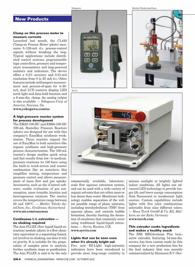
Clamp on this process meter to
measure currents
Launched last month, the CL420
Clamp-on Process Meter (photo) mea-
sures 0–120-mA d.c. process-control
signals without breaking the loop.
Typical applications include distrib-
uted control systems, programmable
logic controllers, pressure and temper-
ature transmitters and loop-powered
isolators and indicators. The device
offers a 0.2% accuracy and 0.01-mA
resolution from 0 to 20 mA d.c. Other
features include milliampere measure-
ment and percent-of-span for 4–20-
mA, dual LCD numeric display, LED
torch light and data-hold function and
a 6-mm-dia. clamp. An analog output
is also available. — Yokogawa Corp. of
America, Newnan, Ga.
www.yokogawa.com/us
A high-pressure reactor system
for process development
The EM20-100-HC and EM60-100-HC
100-mL Hastelloy Pressure Reactors
(photo) are designed for use with this
company’s EasyMax synthesis work-
station. These reactors expand the
use of EasyMax to both autoclave-like
organic synthesis and high-pressure
process characterization. The 100-mL
reactor’s design enables quick setup
and fast results from low- to medium-
pressure reactions (to 100 bars) using
the built-in touch-screen and reactor
combination like an autoclave; this
simplifies mixing, temperature and
pressure control and allows measure-
ment of mass flow and gas uptake.
Accessories, such as the iControl soft-
ware, enable evaluation of gas con-
sumption, mass transfer, kinetics and
heterogeneous catalysis. The reactor
covers the temperature range between
20 and 180°C. — Mettler Toledo Au-
toChem, Inc., Greifensee, Switzerland
www.mt.com/easymax
Continuous L-L extraction —
no shaking required
The Asia FLLEX (flow liquid-liquid ex-
traction) module (photo) is a flow chem-
istry equivalent to a separating funnel,
yet involves no shaking, nor does it rely
on gravity. It is suitable for the prepa-
ration of samples prior to analysis,
further synthetic steps or purification.
The Asia FLLEX is said to be the only
commercially available, laboratory-
scale flow aqueous extraction system,
and can be used with a wide variety of
organic solvents that are either more or
less dense than water. Membrane tech-
nology enables separation of the wid-
est possible range of phase mixtures,
including tetrahydrofuran (THF) from
aqueous phase, and controls bubble
formation, thereby limiting the forma-
tion of emulsions that commonly occur
using traditional liquid-liquid extrac-
tions. — Syrris, Royston, U.K.
www.syrris.com
Lights that can be seen even
when it’s already bright out
Five new EZ-Light high-intensity
indicators have been introduced to
provide clear, long-range visibility in
intense sunlight or brightly lighted
indoor conditions. All lights use ad-
vanced LED technology to provide lon-
ger life and lower energy consumption
than fluorescent or incadescent light
sources. Custom capabilities include
lights with five color combinations
selectable from nine different colors.
— Hans Turck GmbH & Co. KG, Mül-
heim an der Ruhr, Germany
www.turck.com
This extruder cooks ingredients
and makes a healthy snack
The ZSK MEGAvolume Plus twin-
screw extruder, featuring 54-mm-dia.
screws, has been custom made by this
company for a new production line for
the food industry that was recently
commercialized by Dinnissen B.V. (Sev-
24I-4 CHEMICAL ENGINEERING WWW.CHE.COM OCTOBER 2012
New Products
Yokogawa Mettler Toledo AutoChem
Syrris

enum, The Netherlands). Tradenamed
Magi-N.ext (photo), the new production
line permits the production of a wide
range of preserved and healthy conve-
nience foods. The starch components
of different recipes are gelatinized by
means of an extrusion cooking process
in which the shearing action of the
twin screws rapidly causes the temper-
ature of the mixture to rise to 100°C.
In conjuction with the water from the
content in the product, the native raw
starch is gelatinized. A degassing step
removes a large portion of the moisture
via a vacuum system, creating directly
expanded, easily manageable products
obtained at the pelletizing stage by a
centric pelletizer, ZGF 70. — Coperion
GmbH, Stuttgart, Germany
www.coperion.com
This analyzer optimizes biogas
yields, minimizes H2S formation
Designed and manufactured in Ger-
many, the Awi-Flex multifunctional
biogas analyzer (photo) is sup-
plied with a small air
compressor that regu-
lates air injection into
the digester (above
the sludge level) to
between 0.5 and 1
vol.% for breaking
down H2S into elemen-
tal sulfur and water. By accurately
measuring the O2 and H2S levels in
the biogas and using a combination of
PI and fuzzy logic control, H2S levels
can be reduced by up to 80%, says the
company. The Awi-Flex analyzer is
designed to measure CH4, CO2, H2S,
O2 and H2, with up to five measuring
points. It features an integral PC that
enables easy access to recorded data,
sensor parameters and system diag-
nostics, with 4–20-mA, Profibus and
Ethernet communications. — Allison
Engineering, Basildon, U.K.
www.allison.co.uk
Separate components from gases
with this desublimator
The Pluto mini-desublimator is used
to separate substances in applications
such as for tank breathing, thereby
reducing emissions to the environ-
ment, for recovering raw materials
or for protection of downstream vac-
uum generators. Gas comes in con-
tact with cooled lamellae in the Pluto
unit; here, the gas component to be
separated desublimates at or below
its triple point and adheres to the
cold surface in crystalline form. The
www.ksb.com/fl uidfuture
SYSTEM ANALYSIS
Our experts analyse your system and show where you can save energy – with SES System Efワ ciency Services or PumpMeter.
SELECTION
Your KSB partner or KSB EasySelect will help you ワ nd exactly the right pumps and valves.
HIGH-EFFICIENCY
HYDRAULIC COMPONENTS
Top pump and valve performance with minimum loss – all thanks to 140 years of innovation and expertise.
HIGH-EFFICIENCY
DRIVES
Our high-efワ ciency motors even exceed today’s standards.
DEMAND-DRIVEN
OPERATION
Optimised control systems like PumpDrive continuously match pump output to system requirements.
Circle 12 on p. 60 or go to adlinks.che.com/40272-12
Coperion
Allison Engineering

Pluto unit is split into several sectors
to prevent deposits from clogging the
gas inlet. As soon as the desublimator
is loaded, the solid product is melted
off. Separation efficiencies of over
95% are achieved, says the manufac-
turer. The Pluto unit can be supplied
in all weldable materials, and can be
used across the temperature range
from –20 to 350°C, as well as within a
pressure range between vacuum and
10 bars. — GEA Luftkühler GmbH,
Bochum, Germany
www.gea.com
Software simulates vibrations to
keep machinery healthy
In order to detect unexpected torsional
and lateral vibrations in mechanical
drive systems, computer simulation
is crucial to determine the dynamic
behavior of rotating machinery. This
company offers a new, re-
vised software package
to simulate both torsional
and lateral vibrations while
also considering nonlinear
characteristics (such as high-
elastic coupling elements, gear
couplings and backlash in gear
stages), steady state and also time-
transient conditions. A software pack-
age for a comprehensive rotordynamic
analysis, including fluid-film bearings
(photo), is also available and inte-
grated into the rotordynamic analysis
simulation system ARMD 5.7 G2. —
ARLA Maschinentechnik GmbH, Wip-
perfuerth, Germany
www.arla.de
Gas cylinder storage simplifi ed
with Website Wizard
This company’s updated Website now
features a Gas Cage Wizard that
makes choosing the right gas cylinder
storage option simpler. Users enter
the height, diameter and the number
of cylinders that need to be stored, and
the Wizard instantly calculates and
suggests the most suitably sized cage
from a standard range of cages. In ad-
dition to a wide range of mesh cages,
enclosures and cabinets, the Website
also provides essential, up-to-date
U.K. Health and Safety Executive
(HSE) information and FAQs. — Gas
Cage Direct, Crawley, U.K.
www.gascagedirect.co.uk
A smart fl ange system for
increased safety
The QVF Supra-Line is com-
patible with two proven flange
systems — the QVF/WPR2002
and the Schott/KF systems —
and thus reduces the number
of technically equivalent com-
ponents required while provid-
ing the user with increased
safety. The Supra-Line ex-
tends the allowable operating
conditions for temperatures up
to 200°C, provides extensive
resistance to acids and sol-
vents, and an even higher
corrosion resistance
due to its fire-pol-
ished flanges. The
Supra-Line flanges
in the nominal
size range from DN
15 to 300 require only one seal per
nominal diameter, regardless of the
shape of the flange. The flange con-
nection features a patented clamp-
ing system with a ringed grounding
element within the groove of the
flange instead of screwed-on lugs. —
De Dietrich Process Systems GmbH,
Mainz, Germany
www.qvf.de
An economical way to distill
large volumes of products
The patented Plate Molecular Still
(photo) is capable of distilling large
quantities of product (10 ton/h and
more), under medium- or high-
vacuum conditions. The system is
suitable for applications involving
temperature-sensitive substances,
such as oils, fats, pharmaceuticals,
vitamins, methyl esters and more.
The product is fed through a distri-
bution system to the outer surface of
the evaporator plates within a cylin-
drical vessel. In this arrangement,
the heated and cooled panels lead
to a high evaporation and conden-
sation surface in the smallest pos-
sible space. As a result, the econom-
ics are more favorable when using
the Plate Molecular Still compared
to more expensive short-path distil-
lation processors, says the company.
— GIG Karasek GmbH, Gloggnitz,
Austria
www.gigkarasek.at
Level control is simplifi ed with
non-steady-state tuning
This company’s software now in-
cludes non-steady-state (NSS) mod-
eling features for integrating control
loops. These tools are said to provide
fast, simple modeling and tuning of
level controls. Unlike temperature,
pressure and flow, level controls
have different dynamics, and these
new tools make it simple to tune
level controls, even while the level
is moving, says the company. NSS
tuning integrates seamlessly with
the company’s PlantTriage and PID
Loop Optimizer software. These tools
also provide capabilities for both
tight control and surge-tank scenar-
ios. NSS modeling is included with
PlantTriage Version 11 and higher,
and with PID Loop Optimizer Ver-
sion 21 and higher. — ExperTune
Inc., Hartland, Wisc.
www.expertune.com
24I-6 CHEMICAL ENGINEERING WWW.CHE.COM OCTOBER 2012
New Products
ARLA Maschinentechnik
GIG Karasek

Granulate and recycle plastics
waste for less energy
Among the products being exhibited at
the Fakuma Plastics Recycling Trade
Show (Friedrichshafen, Germany; Oc-
tober 16–20) is the Granulator SML
45/60 SB (photo) with forced feeding
(patent pending). This unit has a spe-
cial granulator design that can consid-
erably reduce its energy demand, with
a 30 to 50% lower connected load com-
pared to a traditional machine. Pre-
shredded waste and hollow bodies can
thus be recycled in a very economic
way. — Herbold Meckesheim GmbH,
Meckesheim, Germany
www.herbold.com
New piping software slashes
time for modeling workflows
With the new release, EdgeWise MEP
for Autodesk Revit, users can now,
for the first time, bring extracted
pipes, conduits and other cylindrical
mechanical, electrical and plumbing
(MEP) elements directly into Revit.
This new MEP software leverages the
powerful feature-extraction technol-
ogy of EdgeWise to automatically ex-
tract pipe solids from laser scan-point
clouds. These pipe solids can
be automatically connected
into pipe runs, annotated with
EdgeWise MEP, and then
brought directly into Revit
as fully functional Revit pipe
objects. All data, such as di-
ameter, length, elbow bend ra-
dius and more, are also trans-
ferred into Revit. Beta testers
report modeling-time savings
of up to 85% over previous
workflows, says the company.
Future releases will handle
square ducting, cable trays
and other planar objects. —
ClearEdge3D, Herndon, Va.
www.clearedge3d.com
Efficient filter cartridges
that require no precoating
Installed into Viledon sinTexx
filter cartridges, this new cor-
rugated polyester medium
with nanofiber lining (photo)
is said to achieve optimum
performance when dealing
with fine and difficult-to-
handle dust and smoke. Com-
pared to conventional corrugated poly-
ester materials and ePTFE (expanded
polytetrafluoroethylene) membranes,
the Viledon sinTexx media with nano-
fiber lining offers several advantages,
says the manufacturer: Higher collec-
tion efficiency, even during initial op-
eration; lower flow resistance, which
reduces power and compressed-air
consumption and extends their use-
ful lifetime; and customary precoat-
ing is not required. — Freudenberg
Filtration Technologies SE & Co. KG,
Weinheim, Germany
www.freudenberg-filter.com
No membranes required for this
dissolved oxygen sensor
The new 2610 Optical Dissolved Oxy-
gen Sensor utilizes optical technology
to measure dissolved oxygen with
high repeatability and accuracy while
reducing maintenance and energy
costs, says the company. This device
eliminates the need for replacement
membranes and reference solutions
associated with traditional galvanic
or polarimetric measurement tech-
nologies, and therefore has reduced
maintenance costs. The 2610 has
THE CHEMICAL DIVISION
FILLING VISIONS
TURNKEY VISIONS
n process technologies
which are free of interfaces:
stocking – mixing – filling
n complete turnkey plants
from the
HAVER & BOECKER group:
engineering – delivery –
service
HAVER & BOECKER, GermanyPhone: +49 2522 30-271
Fax: +49 2522 30-403E-mail: [email protected]
www.haverboecker.com
M 957-E4
M 957-E4.QXD_Chem_Engineering 10.06.11 09:18 Seite 1
Circle 9 on p. 60 or go to adlinks.che.com/40272-09
Herbold Meckesheim
Freudenberg Filtration Technologies

an optical cap sensor that is
factory calibrated — no field
calibration is necessary — and
built-in ModBus RS485 and
4–20-mA current-loop out-
puts. The sensor can be com-
bined with the new 9900
transmitter, and covers the
range from 0 to 20 mg/L,
0–200% saturation with
accuracies of ±0.1 mg/L
(for 0–8 mg/L) or ±0.2
mg/L (for 8–22 mg/L). —
GF Piping Systems, Tus-
tin, Calif.
www.gfpiping.com
Process more beer with this
larger clarifi er
To be introduced next month at Brau
Beviale 2012 (Nuremberg, Germany;
November 13–15), the AC2500 beer
clarifier (photo) processes up to 600
hL/h of beer, making it suitable for big
breweries. The AC2500 can be used
flexibly for pre-clarification before fil-
tration, green-beer clarification and
for turbidity adjustment in the case of
cloudy beer, such as wheat beer. Like
its smaller predecessors, the AC2500
features the SoftShot bowl discharge
system, in which yeast is separated
from beer and collected in the solids
chamber of the bowl. The system auto-
matically recognizes, by turbidity mon-
itoring, when the bowl is completely
full. The feed system, valves and dis-
charge system have been optimized to
minimize the impact of shear forces. —
Flottweg SE, Vilsbiburg, Germany
www.flottweg.com
A pelletizing system for
smaller-scale production
With a production flowrate of up to
600 kg/h, the Sphero 50 underwater
pelletizing system can be applied in
testing plants and smaller produc-
tion plants with pelletizing options
for virgin polymers, masterbatches,
compounds, recycling, organic and
wood-based polymers, and more. The
entire system is mounted on a mobile
frame with lockable wheels, and can
be easily moved and adapted to dif-
ferent extruders. All components, such
as startup valves, die plates, water
basins and drives are suspended from
a T-bar, can be shifted horizontally
and are easily accessible. Special at-
tention was given to the new design
of the cutter head in order to ensure
the production of evenly shaped, high-
quality pellets, says the manufacturer.
— Maag, Oberglatt, Switzerland
www.maag.com
This large-capacity mill has
design features of smaller ones
The new 36-in. Orbital Bottom Side
Feed Mill (photo) is designed to pro-
cess 3,000–6,000-lb/h capacities, and
combines design features normally
found only in smaller mills, says the
manufacturer. The combination of
the bottom side feed and orbital-mill
design elements is said to offer best-
in-class performance, efficiency and
durability. The orbital distribution
chamber offers multiple injection
points, ensuring even distribution of
material into the grinding chamber,
which results in tighter product dis-
tribution and higher processing rates.
The bottom side-feed modifications
allow for greater process clarification
of product, while reducing wear on the
mill. Traditional C-clamps have been
replaced with bolts to add rigidity, flat
seals have been replaced by O-rings
for tighter sealing, and a new feed-
injector nozzle design allows for easy
adjustments during processing. — The
Jet Pulverizer Co., Moorestown, N.J.
www.jetpulverizer.com
Four headworks processes
preassembled into one package
The complete Pista Works headworks
system (photo) combines several head-
works processes — screening, grit re-
moval and grit washing — into one
skid-mounted package. Each system
is preassembled and shipped directly
to the job site on one truck, thereby
significantly reducing field installa-
tion costs while allowing for a compact
footprint. All components are con-
structed of stainless steel and utilize
patented technologies, including grit-
removal technologies with V-Force
Baffel, S&L Pista Turbo Grit Pump
and the Grit Washer featuring Tri-
Cleanse Technology. The system comes
with a PLC-based control system with
touch-screen, color human machine in-
terface (HMI) and NEMA 4X panel to
operate the entire system. Pista Works
operates peak system flow capacity
of 0.5–7-million gal/d, depending on
the model. — Smith & Loveless, Inc.,
Lenexa, Kan.
www.smithandloveless.com
This concentrate pump operates
with steam, air or more
The new Pivotrol PTF4 is a high-capac-
ity, pressure-powered condensate pump
that covers a wider motive-pressure
range. This new version can be oper-
ated by steam, air or other pressurized
gases, and covers a complete pressure
range of up to 200 psig. The PTF4 incor-
porates dual Pivotrol pumping mecha-
nisms with PowerPivotol technology,
and is backed by a 3-million cycles or
five-year extended warranty, which is
available as an option. Patented vent-
assist valves release pressure in the
pump during the exhaust stroke, for
faster filling or overall cycling, leading
to higher capacities. — Spirax Sacro,
Blythewood, S.C.
www.spirax.com ■Gerald Ondrey
24I-8 CHEMICAL ENGINEERING WWW.CHE.COM OCTOBER 2012
New Products
Flottweg
The Jet Pulverizer
Smith & Loveless
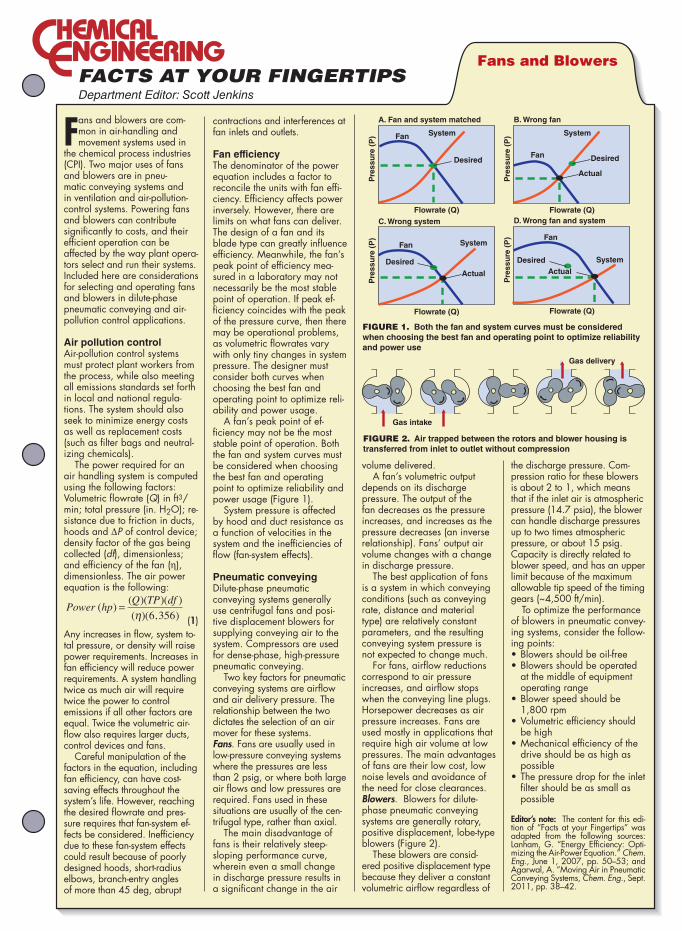
Department Editor: Scott Jenkins
Fans and blowers are com-mon in air-handling and movement systems used in
the chemical process industries (CPI). Two major uses of fans and blowers are in pneu-matic conveying systems and in ventilation and air-pollution-control systems. Powering fans and blowers can contribute significantly to costs, and their efficient operation can be affected by the way plant opera-tors select and run their systems. Included here are considerations for selecting and operating fans and blowers in dilute-phase pneumatic conveying and air-pollution control applications.
Air pollution controlAir-pollution control systems must protect plant workers from the process, while also meeting all emissions standards set forth in local and national regula-tions. The system should also seek to minimize energy costs as well as replacement costs (such as filter bags and neutral-izing chemicals).
The power required for an air handling system is computed using the following factors: Volumetric flowrate (Q) in ft3/min; total pressure (in. H2O); re-sistance due to friction in ducts, hoods and ∆P of control device; density factor of the gas being collected (df), dimensionless; and efficiency of the fan (η), dimensionless. The air power equation is the following: Power hp
Q TP df( )
( )( )( )
( )( , )=
η 6 356 (1)
Any increases in flow, system to-tal pressure, or density will raise power requirements. Increases in fan efficiency will reduce power requirements. A system handling twice as much air will require twice the power to control emissions if all other factors are equal. Twice the volumetric air-flow also requires larger ducts, control devices and fans.
Careful manipulation of the factors in the equation, including fan efficiency, can have cost-saving effects throughout the system’s life. However, reaching the desired flowrate and pres-sure requires that fan-system ef-fects be considered. Inefficiency due to these fan-system effects could result because of poorly designed hoods, short-radius elbows, branch-entry angles of more than 45 deg, abrupt
contractions and interferences at fan inlets and outlets.
Fan efficiencyThe denominator of the power equation includes a factor to reconcile the units with fan effi-ciency. Efficiency affects power inversely. However, there are limits on what fans can deliver. The design of a fan and its blade type can greatly influence efficiency. Meanwhile, the fan’s peak point of efficiency mea-sured in a laboratory may not necessarily be the most stable point of operation. If peak ef-ficiency coincides with the peak of the pressure curve, then there may be operational problems, as volumetric flowrates vary with only tiny changes in system pressure. The designer must consider both curves when choosing the best fan and operating point to optimize reli-ability and power usage.
A fan’s peak point of ef-ficiency may not be the most stable point of operation. Both the fan and system curves must be considered when choosing the best fan and operating point to optimize reliability and power usage (Figure 1).
System pressure is affected by hood and duct resistance as a function of velocities in the system and the inefficiencies of flow (fan-system effects).
Pneumatic conveyingDilute-phase pneumatic conveying systems generally use centrifugal fans and posi-tive displacement blowers for supplying conveying air to the system. Compressors are used for dense-phase, high-pressure pneumatic conveying.
Two key factors for pneumatic conveying systems are airflow and air delivery pressure. The relationship between the two dictates the selection of an air mover for these systems. Fans. Fans are usually used in low-pressure conveying systems where the pressures are less than 2 psig, or where both large air flows and low pressures are required. Fans used in these situations are usually of the cen-trifugal type, rather than axial.
The main disadvantage of fans is their relatively steep-sloping performance curve, wherein even a small change in discharge pressure results in a significant change in the air
volume delivered. A fan’s volumetric output
depends on its discharge pressure. The output of the fan decreases as the pressure increases, and increases as the pressure decreases (an inverse relationship). Fans’ output air volume changes with a change in discharge pressure.
The best application of fans is a system in which conveying conditions (such as conveying rate, distance and material type) are relatively constant parameters, and the resulting conveying system pressure is not expected to change much.
For fans, airflow reductions correspond to air pressure increases, and airflow stops when the conveying line plugs. Horsepower decreases as air pressure increases. Fans are used mostly in applications that require high air volume at low pressures. The main advantages of fans are their low cost, low noise levels and avoidance of the need for close clearances.Blowers. Blowers for dilute-phase pneumatic conveying systems are generally rotary, positive displacement, lobe-type blowers (Figure 2).
These blowers are consid-ered positive displacement type because they deliver a constant volumetric airflow regardless of
the discharge pressure. Com-pression ratio for these blowers is about 2 to 1, which means that if the inlet air is atmospheric pressure (14.7 psia), the blower can handle discharge pressures up to two times atmospheric pressure, or about 15 psig. Capacity is directly related to blower speed, and has an upper limit because of the maximum allowable tip speed of the timing gears (~4,500 ft/min).
To optimize the performance of blowers in pneumatic convey-ing systems, consider the follow-ing points: •Blowersshouldbeoil-free•Blowersshouldbeoperated
at the middle of equipment operating range
•Blowerspeedshouldbe1,800 rpm
•Volumetriceficiencyshouldbe high
•Mechanicaleficiencyofthedrive should be as high as possible
•Thepressuredropfortheinletfilter should be as small as possible
Editor’s note: The content for this edi-tion of “Facts at your Fingertips” was adapted from the following sources: Lanham, G. “Energy Efficiency: Opti-mizing the Air-Power Equation.” Chem. Eng., June 1, 2007, pp. 50–53; and Agarwal, A. “Moving Air in Pneumatic Conveying Systems, Chem. Eng., Sept. 2011, pp. 38–42.
Fans and Blowers
System
Desired
Fan
Flowrate (Q)
A. Fan and system matched
Pre
ssu
re (
P) System
DesiredFan
Flowrate (Q)
B. Wrong fan
Pre
ssu
re (
P)
System
Desired
Fan
Flowrate (Q)
C. Wrong system
Pre
ssu
re (
P)
Actual
SystemDesired
Fan
Flowrate (Q)
D. Wrong fan and system
Pre
ssu
re (
P)
ActualActual
Gas delivery
Gas intake
FIGURE 1. Both the fan and system curves must be considered
when choosing the best fan and operating point to optimize reliability
and power use
FIGURE 2. Air trapped between the rotors and blower housing is
transferred from inlet to outlet without compression
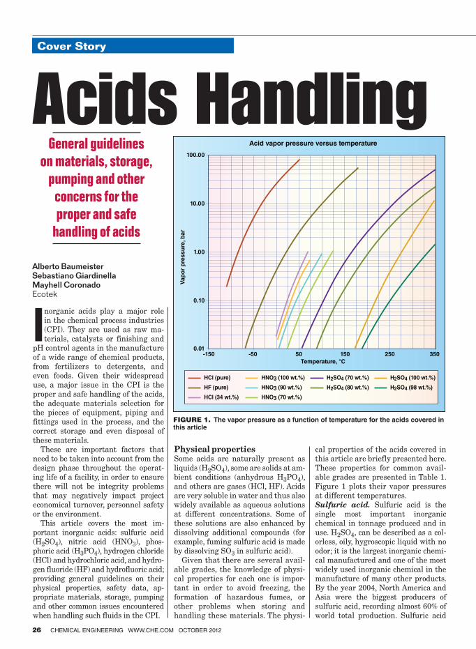
Inorganic acids play a major role
in the chemical process industries
(CPI). They are used as raw ma-
terials, catalysts or finishing and
pH control agents in the manufacture
of a wide range of chemical products,
from fertilizers to detergents, and
even foods. Given their widespread
use, a major issue in the CPI is the
proper and safe handling of the acids,
the adequate materials selection for
the pieces of equipment, piping and
fittings used in the process, and the
correct storage and even disposal of
these materials.
These are important factors that
need to be taken into account from the
design phase throughout the operat-
ing life of a facility, in order to ensure
there will not be integrity problems
that may negatively impact project
economical turnover, personnel safety
or the environment.
This article covers the most im-
portant inorganic acids: sulfuric acid
(H2SO4), nitric acid (HNO3), phos-
phoric acid (H3PO4), hydrogen chloride
(HCl) and hydrochloric acid, and hydro-
gen fluoride (HF) and hydrofluoric acid;
providing general guidelines on their
physical properties, safety data, ap-
propriate materials, storage, pumping
and other common issues encountered
when handling such fluids in the CPI.
Physical propertiesSome acids are naturally present as
liquids (H2SO4), some are solids at am-
bient conditions (anhydrous H3PO4),
and others are gases (HCl, HF). Acids
are very soluble in water and thus also
widely available as aqueous solutions
at different concentrations. Some of
these solutions are also enhanced by
dissolving additional compounds (for
example, fuming sulfuric acid is made
by dissolving SO3 in sulfuric acid).
Given that there are several avail-
able grades, the knowledge of physi-
cal properties for each one is impor-
tant in order to avoid freezing, the
formation of hazardous fumes, or
other problems when storing and
handling these materials. The physi-
cal properties of the acids covered in
this article are briefly presented here.
These properties for common avail-
able grades are presented in Table 1.
Figure 1 plots their vapor pressures
at different temperatures.
Sulfuric acid. Sulfuric acid is the
single most important inorganic
chemical in tonnage produced and in
use. H2SO4, can be described as a col-
orless, oily, hygroscopic liquid with no
odor; it is the largest inorganic chemi-
cal manufactured and one of the most
widely used inorganic chemical in the
manufacture of many other products.
By the year 2004, North America and
Asia were the biggest producers of
sulfuric acid, recording almost 60% of
world total production. Sulfuric acid
Feature Report
26 CHEMICAL ENGINEERING WWW.CHE.COM OCTOBER 2012
Cover Story
Alberto BaumeisterSebastiano GiardinellaMayhell CoronadoEcotek
General guidelines
on materials, storage,
pumping and other
concerns for the
proper and safe
handling of acids
Acids Handling100.00
Acid vapor pressure versus temperature
10.00
1.00
0.10
0.01-150 -50 50 150
Temperature, °C
Vap
or
pre
ssu
re, b
ar
250 350
HCl (pure)
HF (pure)
HCl (34 wt.%)
HNO3 (100 wt.%)
HNO3 (90 wt.%)
HNO3 (70 wt.%)
H2SO4 (70 wt.%)
H2SO4 (80 wt.%)
H2SO4 (100 wt.%)
H2SO4 (98 wt.%)
FIGURE 1. The vapor pressure as a function of temperature for the acids covered in this article

is manufactured by the combustion of
sulfur with dry air to form sulfur diox-
ide (SO2), then sulfur trioxide (SO3) is
produced through a catalytic conver-
sion. Finally, sulfuric acid is obtained
after absorption of SO3 in water.
Sulfuric acid is a strong acid and a
strong oxidizing agent; therefore it re-
acts violently with bases, combustible,
reducing materials, water and organic
compounds with the evolution of heat.
It is highly corrosive to most common
metals and forms a flammable/explo-
sive gas.
Sulfuric acid is mostly used in the
manufacturing of fertilizers, organic
pigments, explosives and more. As a
strong electrolyte it is used in electro-
plating baths for pickling, and for op-
erations in the production of iron and
steel. Moreover, it is extensively used
as a solvent for ores and as a catalyst
in the petroleum industry.
Nitric acid. HNO3 is a solution of ni-
trogen dioxide (NO2) in water; it is a
colorless to light-brown fuming liquid
with an acrid suffocating odor. Nitric
acid is the second most important in-
dustrial acid; it is a highly oxidizing
agent, used in the manufacture of
chemicals, explosives, fertilizers, steel
pickling and metal cleaning. However,
the largest use for nitric acid is for the
production of fertilizers.
Nitric acid is a strong acid that re-
acts violently in the presence of strong
bases, reducing agents and combusti-
ble fluids, such as turpentine, charcoal
and alcohol. It is corrosive to metals,
forming flammable or explosive gas.
Nitric acid also reacts violently with
organic compounds.
Phosphoric acid. H3PO4 or or-
thophosphoric acid is a white solid
with a melting point of 42°C, which is
highly soluble in water, non-toxic and
a relatively weak acid.
H3PO4 is the third most important
acid in industry. It is used mostly in
the production of phosphate fertiliz-
ers; but also in the manufacturing of
agricultural feeds, soaps, detergents,
waxes; and in the food industry as pre-
servative, acidifier, clarifier or flavor
enhancer; among other uses.
H3PO4 has two main methods of pro-
duction: the wet process and electric
furnace. It is commercially available
at concentrations of 75, 80, 85 and 87
wt.% of PO3. Higher concentrations,
such as 105 wt.% (superphosphoric)
and 115 to 118 wt.% (polyphosphoric)
are also available. “Pure” or “techni-
cal grade” phosphoric acid is usually
found at 85 wt.%.
Hydrogen chloride and hydrochlo-
ric acid. Hydrochloric acid is a solu-
tion of the gas hydrogen chloride; it is
a poisonous, highly corrosive, hazard-
ous liquid that reacts with most met-
als to form explosive hydrogen gas. Its
appearance varies from pale yellow to
colorless, according to purity.
Hydrochloric acid has many appli-
cations in the production of organic
and inorganic compounds such as fer-
tilizers, chlorides, dyes and more. HCl
plays an important role in pickling
of steel, acid treatment of oil wells,
chemical cleaning and processing, and
ore reduction among others.
When boiling all aqueous solutions,
HCl forms an azeotropic constant-
boiling mixture that contains 20.24%
HCl and boils at 110°C (230°F).
Hydrogen fluoride and hydroflu-
ric acid. Anhydrous hydrogen fluo-
ride (AHF) is a clear, colorless, corro-
sive fuming liquid with an extremely
sharp odor. It easily dissolves in water
to form hydrofluoric acid.
HF forms dense white vapor clouds
if released. Both liquid and vapor can
cause severe burns to all parts of the
body. Specialized medical treatment is
required for all exposures.
HF occurs naturally in volcanic
gases and may result from industrial
activities, such as coal-burning, and
the manufacture or production of alu-
minum, phosphate fertilizer, steel and
other chemical derivatives.
Commercially, HF is used to man-
ufacture fluoropolymers, pharma-
ceuticals, aluminum, stainless steel,
CHEMICAL ENGINEERING WWW.CHE.COM OCTOBER 2012 27
TABLE 1. PHYSICAL AND CHEMICAL PROPERTIES OF ACIDS [1–5]
Units H2SO4 H3PO4 HNO3 HF HCl
CAS Number 7664-93-97664-38-7
7697-37-2 7664-39-3 7647-01-0
Molecular weight
g/gmol 98.079 97.994 63.01 20.01 36.46
GradeConcen-trated
Fertilizer TowerFuming, 65% oleum
Pure WFNA Strong CommonGas (an-hydrous)
Aqueous AqueousGas (an-hydrous)
Aqueous
Aqueous. Technical Grade22°Be
Concentra-tion
wt.% 98 78–80 62–7035 H2SO4,65 SO3
75–85 100 90 68 100 48–51 40 100 50 33
Physical state
Liquid Liquid Liquid Liquid Solid Liquid Liquid Liquid Gas Liquid Liquid Gas Liquid Liquid
Color Colorless Colorless Colorless Colorless Colorless Colorless Colorless Colorless Colorless Colorless Colorless Colorless Colorless Colorless
Odor Odorless Odorless Odorless Odorless OdorlessPungent odor
Pungent odor
Disagree-able (can cause choking)
Pungent odor
Acrid Odor
Acrid odorPungent odor
Pungent odor
Pungent odor
Boiling point (760 mmHg)
°C 340 200 155.85 151.1 212.8 86 120.5 121 20 108 112.2F –85 100 83
Vapor density (air = 1)
3.4 3.4 2.2 2.5D 0.7 1.97 1.3 0.62 1.267
Specific grav-ity (H2O=1)
1.83 1.72 1.57 1.56 1.87 1.50 1.50 1.50 1.17 1.14 1.03 1.16
Liquid density (at 20ºC)
g/mL 1.8361 1.7272B 1.6105C 1.5533 1.579A 1.5129 1.4826 1.4048 1.202 1.159 1.251 1.164
Melting point °C 10.5 –4.29 –36.55 –36.98 42.2 –42 –41.6 –83 –40 –62 –114 –46.2
Dynamic viscosity (at 20ºC)
cP 20.5 6.5 3.52 2.68E 2
Notes: A Liquid Density of phosphoric acid at 75% B Liquid density of sulfuric acid at 80% C Liquid density of sulfuric acid at 70% D Vapor density of nitric acid at 65% E Dynamic viscosity obtained after extrapolation F Boiling point at 38.2%

Cover Story
28 CHEMICAL ENGINEERING WWW.CHE.COM OCTOBER 2012
high-octane gasoline, electronics (mi-
crochips and printed circuit board
cleaning) and uranium isotopes. It is
also used to etch glass or metal.
Safety and emergency responseBecause acids are mostly hazardous
chemicals, their toxicity levels and in-
compatibilities need to be taken into
account when storing and transport-
ing them, as well as how to respond in
the event of a spillage.
Permissible exposure limits (PEL) for
hazardous materials are given by the
U.S. Occupational Safety and Health
Administration (OSHA) regulations:
29 CFR 1910.1000, 29 CFR 1926.55
and 29 CFR 1915.1000 for the general,
construction and maritime industries,
respectively. Other toxicity levels, such
as the Recommended Exposure Limit
(REL) and Immediately Dangerous
to Life and Health Concentrations
(IDLH) are published in the U.S. Na-
tional Institute of Occupational Safety
and Health (NIOSH) Pocket Guide
to Chemical Hazards. The chemical
incompatibilities, health effects and
other concerns when handling or stor-
ing hazardous chemicals are also given
in the NIOSH Pocket Guide.
In the U.S., transportation of these
acids or other hazardous materials
is subject to the U.S. Department of
Transportation Pipeline and Hazard-
ous Materials Safety Transportation
regulations. Transportation of hazard-
ous materials in various forms (bulk,
pipeline or tank cars) is subject to
Title 49 of the Code of Federal Regula-
tions (49 CFR).
In the event of spills of these acids
or other hazardous materials, only
properly trained personnel such as
firemen and policemen (or properly
trained plant personnel) should be in-
volved in the emergency response and
containment of the product.
The Emergency Response Guide-
book 2008 (ERG2008) provides guide-
lines for managing emergencies when
hazardous chemicals are involved.
This guidebook is available in printed
form, and can also be downloaded in
convenient electronic form, includ-
ing applications for smart phone that
allow for quick searches of the chemi-
cals and their associated guides. A new
version of the Emergency Response
Guidebook is scheduled for release
this year (2012).
The chemical safety data for the
acids covered in this article, including
toxicity levels, incompatibilities and
emergency response guides are sum-
marized in Table 2.
Materials selectionThe materials of construction, as well
as any lining or internal coating re-
quirements should be determined by a
materials expert based on the acid, its
concentration and storage conditions.
Aqueous acid solutions are very cor-
rosive, and usually require special ma-
terials depending on the temperature
or phase.
Some recommendations are given
regarding the correct material selec-
tion depending on acid, such as in the
following reference for H2SO4: NACE
RP0391 — Materials for the Han-
dling and Storage of Concentrated
(90 to 100%) Sulfuric Acid at Ambient
Temperatures; HF: NACE 5A171 —
Materials for Storing and Handling
Commercial Grades of Aqueous Hy-
drofluoric Acid and Anhydrous Hydro-
gen Fluoride.
Depending on the acid and stor-
age, transport or process conditions,
interior coatings or linings could also
be considered. For instance, rail tank
cars transporting concentrated sulfu-
ric acid should be internally coated
according to NACE SP0592 — Appli-
cation of a Coating System to Interior
Surfaces of New and Used Rail Tank
Cars in Concentrated (90 to 98%) Sul-
furic Acid Service.
TABLE 2. TOXICITY AND EMERGENCY RESPONSE DATA
H2SO4 H3PO4 HNO3 HF HCl
PEL (OSHA) [6–8]
1 mg/m3 1 mg/m3 TWA 2 ppm, 5 mg/m3 TWA
3 ppm, 2 mg/m3 TWA 5 ppm, 7 mg/m3 ceiling
REL (NIOSH) [9]
1 mg/m3 TWA 1 mg/m3 TWA;3 mg/m3 STEL
2 ppm, 5 mg/m3 TWA;4 ppm, 10 mg/m3 STEL
3 ppm, 2.5 mg/m3 TWA;6 ppm, 5 mg/m3 (15 min) ceiling
5 ppm, 7 mg/m3 ceiling
IDLH (NIOSH) [9]
15 mg/m3 1,000 mg/m3 25 ppm 30 ppm 50 ppm
Incompat-ibilities & Reactivities
Organic materials, chlorates, carbides, fulminates, water, powdered metals. Reacts with water to produce heat. Corrosive to metals
Strong caustics, most metals, Reacts with metals to form H2 gas. Do not mix with solutions containing bleach or ammonia
Combustible materi-als, metallic powders, hydrogen sulfide, car-bides, alcohol. Reacts with water to produce heat. Corrosive to metals
Metals, water or steam. Cor-rosive to metals. Attacks glass and concrete
Hydroxides, amines, alkalis, copper, brass, zinc. Hydrochlo-ric acid is highly corrosive to most metals
UN Listing Number
1830: sulfuric acid; sulfuric acid, with more than 51% acid1831: sulfuric acid, fuming; sul-furic acid, fuming, with less than 30% free sulfur trioxide; sulfuric acid, fuming, with not less than 30% free sulfur trioxide1832: sulfuric acid, spent
2796: sulfuric acid, with not more than 51% acid
1805: phosphoric acid; phosphoric acid, liquid; phos-phoric acid, solid; phosphoric acid, solution3453: phosphoric acid, solid
2031: nitric acid, other than red fuming2032: nitric acid, fuming; nitric acid, red fuming
1052: hydro-gen fluoride, anhydrous
1790: hydro-fluoric acid
1050: hydrogen chloride, anhy-drous2186: hydrogen chloride, refriger-ated liquid
1789: hy-drochloric acid; hydro-chloric acid, solution
Emergency Response [10]
Guide 137 Guide 157 Guide 154 Guide 157 Guide 125 Guide 157 Guide 125 Guide 157
Notes: PEL: Permissible exposure limit REL: Recommended exposure limit IDLH: Immediately dangerous to life or health concentration
TWA: Total weighted average STEL: Short time exposure limit ERG: Emergency Response Guidebook

CHEMICAL ENGINEERING WWW.CHE.COM OCTOBER 2012 29
Tables 3–8 list some common metal
alloys used in the CPI, along with their
general acceptable use ranges (concen-
trations and temperatures) for each of
the acids covered in this article.
Storage tanksUsually aboveground storage tanks
(ASTs) are used to store acid as they
facilitate accessibility to tanks and
ancillary equipment for inspection
and maintenance. The storage tank
should be sized for at least 50% more
volume than required.
Tanks for acid storage are usually
built of either metal (lined or non-
lined), or fiber reinforced plastic (FRP).
Metal tanks offer a higher durability,
and can also resist higher stresses or
impacts; whereas FRP tanks are eco-
nomical, usually chemically inert, and
can be a good alternative for low-vol-
ume, short storage times.
The mechanical design of tanks for
acid storage usually follows either of
the following codes:
•API STD 650 — Welded SteelTanks for Oil Storage: for vertical
tanks with flat bottoms and oper-
ating pressures less than 0.14 barg
(2.5 psig)
•API STD 620 — RecommendedRules of Construction of Large,
Welded, Low Pressure StorageTanks: for vertical tanks with flat
bottoms and operating pressures
between 0.14 barg and 1.03 barg
(2.5 psig and 15 psig)
•ASMEBPVCode,SectVIII,Div1:for other operating pressures
Special design criteria, such as par-
ticular corrosion allowances or nozzle
design, are also considered in acid
storagetanks—eitherbyspecialcom-
pany or supplier criteria, or from pro-
fessional associations. For instance,
concentrated sulfuric acid tanks de-
sign should followNACE SP0294—Design, Fabrication, and Inspectionof Storage Tank Systems for Concen-
trated Fresh and Process Sulfuric Acid
and Oleum at Ambient Temperatures.
Tanks should allow access to the
top nozzles and the vent system, and
offer an appropriate facility for sam-
pling. Periodically, it is necessary to
homogenize the contents of the tank,
because the acid that remains on the
surface establishes a vapor-liquid
equilibrium in which toxic and corro-
sive gases are released, so a recircula-
tion system is recommended.
Special attention should be given to
the acid physical properties in stor-
age to prevent freezing, high corrosion
rates or vaporization.
In general, corrosion rates increase
at higher temperatures, so acids
should be stored at the lowest pos-
sible temperature without freezing
the acid. Higher corrosion rates could
also result from heating of the metal
surfaces due to sun radiation, so the
tank exterior should be painted with
a radiation reflecting color, such as
white. Another regular measure to
maintain acids at an appropriate
temperature is coating the tank with
an adequate material such as vinyl-
based materials.
In places where the storage tem-
perature could be below the acid
freezing point, storage tanks and ves-
sels should be provided with heating
facilities, such as plate coils mounted
on the outside of the tank wall, or ex-
ternal heat exchangers connected to
TABLE 3. MATERIALS OF CONSTRUCTION, CLADDING & LINING [12]
Materials of
construction
H2SO4
AluminumAluminum alloys may be used to handle dilute (concentration below 10%) and concentrated acid (above 98%). It suffers corrosion for handling sulfuric acid in a range of concentration of 40–95 %
Carbon steelIt can be used to handle concentrated sulfuric acid at ambient temperatures under static and low-velocity condition. Corrosion resistance depends on temperature, acid concentration, iron content and flowrates
Cast IronAlloys with 14.5% content of silicon have shown best resistance to corrosion for sulfuric acid handling in all concentrations at temperatures up to the boiling point
Copper Copper and copper alloys are not suitable for sulfuric acid handling
LeadIt has shown high resistance to corrosion in sulfuric acid handling up to 70% concentration. Although, this material is not recommended for pumps or valves
NickelNickel 200 demonstrates good tolerance to sulfuric acid when it is handled at low or moder-ate temperatures
NiobiumIt can be used for handling sulfuric acid at concentrations below 95% under oxidizing condi-tions
GoldExhibits excellent resistance to sulfuric acid up to 250°C (480°F) and is used when no corro-sion can be tolerated
Platinum Resists sulfuric acid in all concentrations and temperatures
Palladium It is attacked by sulfuric acid in the presence of air
Rhodium In wrought or cast form rhodium is not recommended for handling sulfuric acid
Stainless steelConcentrated sulfuric acid turns extremely corrosive in presence of 316 and 304 stainless steels. The conventional austenitic grades show good resistance in dilute or highly concen-trated acid at moderate temperatures
ZincIt is slowly dissolved by dilute sulfuric acid; corrosion resistance depends on the concentra-tion of the acid and the purity of the metal
TABLE 4. MATERIALS OF CONSTRUCTION, CLADDING & LINING [12]
Materials of
construction
H3PO4
Aluminum
Aqueous solutions of phosphoric acid with concentration of 5 to 85% are highly corrosive for alloys 1100. Consequently this material is not recommended for phosphoric acid han-dling
Cast Iron
All cast irons can be considered to handle phosphoric acid; although the presence of contaminants must be previously evaluated since it can provoke severe cases of corrosion. High-silicon cast irons are ideal to manage phosphoric acid in all concentrations at any temperature, no presences of fluoride ions (F-) are allowed
Copper Copper and copper alloys can be used to manage pure phosphoric acid solutions in heat-exchanger tubes, pipes and fittings. System impurities can accelerate the rate of corrosion more than acid concentration
LeadIt is extensively used in the manufacture of phosphoric acid. It is highly resistant to corro-sion
NickelNickel alloys are appropriate for handling phosphoric acid. For dilute acid alloys 20Cb-3 and 825 are recommended; for concentrated acid at high temperatures alloy B-2 offers the highest corrosion resistance
Niobium Resistant to corrosion for handling acid at temperatures below 100°C in all concentrations
SilverResistant to corrosion for handling acid at temperatures between 160 and 200°C in all concentrations
TantalumResistant to corrosion for handling acid at temperatures up to the boiling point in all con-centrations in absence of fluoride ions (F–)
Stainless SteelConventional austenitic stainless steel has shown elevated corrosion resistance for all con-centrations of phosphoric acid up to 65°C (150°F)

Cover Story
30 CHEMICAL ENGINEERING WWW.CHE.COM OCTOBER 2012
the tank. Internal heating coils are
not recommended, because excess
temperature in the coil walls acceler-
ates corrosion and could cause leaks.
Also, high-pressure steam is not rec-
ommended as a heating medium since
heat exchange surfaces could exceed
100°C, causing severe corrosion.
Pressurized storage is required
when the vapor pressure exceeds the
atmospheric pressure at the storage
temperature.
Common guidelines for acid storage
tank design are summarized in Chem.
Eng. May 2008, Facts at your Finger-
tips: Acid Storage.
When storing acids above ground,
containment is also an issue. Tanks
should be properly diked, or double
walled, to contain spills. In general,
containment should be at least for one
tank volume (if not properly drained),
or less provided there is adequate
drainage to an acid neutralization
pit, with blockage valves accessible
to operators. Local code requirements
should also be addressed when de-
signing acid-tank containment; for
instance, the U.S. State of Florida has
specific requirements as given by Rule
62-762.891 — Mineral Acid Storage
Tank Requirements.
PumpsThe design basis should be set before
selecting a pump, that is, the operat-
ing conditions such as temperature,
suction pressure, acid concentration,
and so on.
A primary issue that must be taken
into account while pumping acids is
safety, so, the selected pump for the
system cannot leave place for leak-
age; this is an advantage regularly
offered by vertical submerged pumps
over horizontal pumps. Also, material
selection guidelines shall be followed
to avoid casing, impeller or other in-
ternals damage.
Piping and fittingsSelecting pipe material and designing
the pipe system is a very important
issue in a plant, especially while han-
dling acids. The system must ensure
the acid is transported safely and ef-
ficiently. Piping should have as few
flanges as possible, so the chance of
having leaks becomes negligible.
In order to select the piping mate-
rial, the following aspects have to be
defined: acid concentration, transport
temperature, phase, fluid velocity,
type of flow, impurities in the acid and
solids presence.
Corrosion is often related to an
acid’s velocity. In order to maintain a
low velocity of the fluid, a bigger pipe
diameter is suggested.
ValvesValves are used for various functions,
including the following:
For blocking, gate valves or plug
valves are regularly used. However,
plug valves are preferred for this ser-
vice, to ensure proper valve operation.
For control, globe or butterfly valves
are suitable; they can be manually op-
erated or be fitted with actuators.
Materials for different parts of the
valves (disk, stem and seat) should be
selected according to the acid concen-
tration and operating conditions, by
consulting the valve manufacturer.
Some common materials according
to the acid to be handled are presented
in Tables 9–13.
Acid handlingSulfuric acid. Sulfuric acid must be
stored separately from combustible
and reducing substances in a well-
ventilated environment at tempera-
tures below 23°C (73.4°F). Concen-
trated acid needs to be isolated from
water, as it may react violently, releas-
TABLE 6. MATERIALS OF CONSTRUCTION, CLADDING & LINING [12]
Materials of con-
struction
HF
Aluminum Unsuitable for handling hydrofluoric acid
Stainless steelStainless-steel type 304 has a good performance for handling anhydrous hydrogen fluoride up to 200°C (390°F), it has poor resistance to dilute or concentrated hydrofluoric acid. On the other hand stainless-steel type 316 can be used for handling dilute acid at low temperatures
CopperThe use of copper alloys is affected by aeration and velocity, its corrosion resistance depends on the concentration and temperature
LeadFair corrosion resistance in a wide range of concentration and temperatures for handling hydrofluoric acid. Not recommended for handling dilute acid
MolybdenumIt offers great corrosion resistance to aqueous and anhydrous hydrofluoric acid with concen-trations up to 50%, below 100°C (212°F)
NickelNickel 200 is ideal for handling hot anhydrous hydrogen fluoride vapor, but it is not recom-mended for handling hydrofluoric acid in aqueous solutions
Niobium Unsuitable for handling hydrofluoric acid
Tin Unsuitable for handling hydrofluoric acid
Titanium Unsuitable for handling hydrofluoric acid
Zirconium Unsuitable for handling hydrofluoric acid
TABLE 5. MATERIALS OF CONSTRUCTION, CLADDING & LINING [12]
Materials of con-
struction
HNO3
AluminumAluminum alloys commonly used for nitric acid services are 1100 and 3003. Corrosion de-pends on temperature and concentration of the acid. Aluminum alloys are compatible with ni-tric acid at temperatures up to at least 71°C (160°F) when it is inhibited by hydrofluoric acid
Cast ironCast iron can be used for handling concentrated nitric acid under control conditions such as low temperature and low velocity. Corrosion attacks when handling dilute nitric acid
Stainless steelFor concentrations of 0 to 65%, most AISI 300-Series stainless steel has shown great corro-sion resistance for temperatures up to the boiling point
Copper Not suitable for use in nitric acid
Lead It can be used for concentration between 52 and 70%
Molybdenum Not suitable for use in nitric acid
NickelNickel alloys are widely used in the production of nitric acid. Alloy 617 offers an excellent performance and corrosion resistance for handling nitric acid at high temperatures in the catalyst-support grids in high pressure plants
Niobium It is completely resistant to nitric acid in all concentration at temperatures below 100°C
Gold It is resistant to nitric acid in concentrations up to 50% above that it is attack by corrosion
Palladium It is vulnerable to attack from corrosion when nitric acid is in presence of air
RhodiumIn wrought or cast form rhodium is resistant to corrosion produced by concentrated nitric acid at 100°C
Silver Not suitable for use in nitric acid
Tin Not suitable for use in nitric acid. Complex reaction occurs
Titanium
Appropriate for handling nitric acid at any concentration in temperatures below the boiling point. As temperatures exceed 80°C (175°F), corrosion becomes stronger depending on nitric acid purity. Titanium alloys can’t be used for red fuming nitric acid due to a violent reaction that can take place in the system

CHEMICAL ENGINEERING WWW.CHE.COM OCTOBER 2012 31
ing heat. If sulfuric acid needs to be
diluted or combined with water, then
it has to be added to water carefully.
To manipulate sulfuric acid, proper
personal protective equipment, such
as gloves, a vapor respirator when
ventilation is inadequate, face shield
and full suit shall be used.
Nitric acid. Nitric acid must be
stored separately in a corrosion resis-
TABLE 8. MATERIALS OF CONSTRUCTION, CLADDING & LINING
ACIDS COMMON ALLOYS
H2SO4
For dilute and intermediate sulfuric acid (between 40 and 80% concentration) Incoloy alloys 25-6MO, 825, 020 and Inconel alloy G-3 have shown excellent corrosion resistance for temperatures up to 50 °C (120°F). When handling aggressive acid, Inconel alloys 625, 622, C-276 and 686 are suit-able. For reducing conditions, Monel alloy 400 is appropriate in the absence of air for temperatures up to boiling point for concentrations below 15%. For storage of H2SO4, Monel alloy 400 can be used at room temperatures up to 80% concentration. Hastelloy B3, C-2000 and G-30 are also suitable for handling sulfuric acid
HNO3
Chromium enhances corrosion resistance in alloys while handling nitric acid, due to this fact, Incoloy alloy 800 and 825 are adequate for nitric acid at all concentrations for temperatures up to the boiling point. Inconel alloy 600 and C-276 also offer good corrosion resistance to nitric acid for concentra-tion over 20% at room temperature; alloy 690 has shown better corrosion resistant because its chromium content is higher. Hastelloy G-30 alloy and G-35 offer excellent corrosion resistance for this same reason
H3PO4
When handling phosphoric acid, Incoloy alloys 825, 020 and 25-6MO, as well as Inconel alloy G-3 are suitable and regularly used. For extreme conditions such as high temperature and high amount of impurities or halides contaminants, Inconel alloys 625, 622, C-276 and 686 are recommended. Has-telloy alloys B-3 and G-30 stand phosphoric acid in all concentrations and temperatures. Hastelloy alloy G-35 was especially designed for phosphoric acid wet processing in fertilizers manufacture
HCl
Incoloy alloys 25-6MO, 825 and 020, and Inconel alloy G-3 are used for dilute hydrochloric acid handling. Another alloy that offers good corrosion resistant in concentrations below 10% with aer-ated conditions at room temperature is Monel alloy 400. Nickel alloy 200 can be used at room temperature for concentrations up to 30% as well. For environments that contemplate the presence of oxidizing contaminants and hot hydrochloric acid, Inconel alloys 625, 622, C-276 and 686 are rec-ommended. Hastelloy alloys B-3, C-2000 and G-30 are also suitable for handling hydrochloric acid, at all concentrations and temperatures
HF
The formation of fluoride films is key on engineering materials in order to offer good corrosion-resistance rates while handling hydrofluoric acid. Monel alloy 400 is widely used for this purpose, due to the fact that it has shown excellent corrosion resistance for all hydrofluoric acid services in all concentrations and temperatures up to (and even above) the boiling point. For anhydrous hydrogen fluoride up to 82°C (180°F), Nickel alloy 200 is commonly used. For dilute HF and temperatures up to 70°C (158°F) Inconel alloy 600 can also be used. Other alloys like Hastelloy C-2000 and Hastelloy G-30 are also recommended for handling hydrofluoric acid
TABLE 7. MATERIALS OF CONSTRUCTION, CLADDING & LINING
Materials of con-
struction
HCl
AluminumIt is not appropriate for handling HCl; it has no resistance to corrosion
Cast IronUnalloyed cast iron systems are unsuitable for handling HCl, especially if high velocities are involve. A high-silicon iron alloyed with small amounts of molybdenum, chromium and copper can be used to handle hydrochloric acid up to 95° C (200°F) at all concentrations
Stainless steelCorrosion attacks stainless steel (316) and stainless steel (304) when handling HCl at any concentration or temperature
CopperCopper can be used to handle dilute hydrochloric acid only, due to its sensitivity to velocity, aeration and oxidizing impurities
LeadIt exhibits tolerance to corrosion at 24°C (75°F) and concentrations up to 15%. It is unsuit-able for concentrated acid at higher temperatures
Nickel
Pure nickel and nickel-copper alloys can be used for handling hydrochloric acid below 10% concentration, without air presence, at low temperatures. The lower the concentration the higher can be the temperature of the system; for example, HCl at 0.5% can stand tempera-tures up to 200°C before corrosion attacks the alloy
NiobiumIt has shown excellent corrosion resistance to handle HCl at any concentrations and tem-peratures up to 100°C (212°F)
GoldIt can be used for handling hydrochloric acid at any concentrations and atmospheric pres-sure up to the boiling point
Palladium Unsuitable for handling hydrochloric acid
RhodiumIn cast or wrought form, rhodium has excellent corrosion resistance to handle concentrated hydrochloric acid in temperatures up to 100°C (212°F)
Silver It is very susceptible to aeration when concentration and temperature are high
TantalumIt has shown excellent corrosion resistance to handle HCl at any concentrations under atmospheric pressure and temperatures up to 90°C (195°F). It can be used to handle acid with concentrations below 25% up 190°C (375°F)
Titanium Unsuitable for handling hydrochloric acid
References
1. Perry, R., Green, D. W., & Maloney, J. O. “Perry’s Chemical Engineers’ Handbook,” McGraw-Hill, N.Y., 2008.
2. Davenport, W. G., and King, M. J., Sulfuric Acid Properties, In Sulfuric Acid Manufac-ture: Analysis, Control and Optimization, Elsevier, pp. 287–291, 2006.
3. DKL Engineering, Inc.,. Technical Manual, April 12, 2003. Retrieved July 6, 2012, from Sulfuric Acid Properties: www.sulphuric-acid.com/techmanual/Properties/proper ties_acid_properties.htm
4. Material Safety Data Sheet, Nitric acid, 65% MSDS.
5. Potash Corp., Purified Phosphoric Acid, Tech-nical information bulletin, PCS Sale — In-dustrial Products, 2005.
6. U.S. Dept. of Labor, Occupational Safety and Health Administration (OSHA). Retrieved May 14, 2012, from Regulations: 29 CFR 1910.1000 (General Industry): www.osha.gov/pls/oshaweb/owadisp.show_document?p_table=Standards&p_id=9991
7. U.S. Dept. of Labor, Occupational Safety and Health Administration (OSHA), Re-trieved May 16, 2012, from Regulation: 29 CFR 1926.55 (Construction Industry): www.osha.gov/pls/oshaweb/owadisp.show_document?p_table=Standards&p_id=10628
8. U.S. Dept. of Labor, Occupational Safety and Health Administration (OSHA), Re-trieved May 16, 2012, from Regulation: 29 CFR 1915.1000 (Maritime): www.osha.gov/pls/oshaweb/owadisp.show_document?p _table=standards&p_id=10286
9. National Institute of Occupational Safety and Health, “NIOSH Pocket Guide to Chemical Hazards”, NIOSH Publications, 2007.
10. U.S. Dept. of Transportation, “Emergency Re-sponse Guidebook 2008 (ERG2008)”, 2008.
11. Grossel, Stanley S., Safe, Efficient Handling of Acids, Chem. Eng., July 1998, pp. 88–98.
12. ASM International, (2002). Handbook of Cor-rosion Data, 2002.13. API Std. 620.
14. API Std. 650.
15. ASME Boiler and Pressure Vessel Code Sec. VIII Div 1.
16. DKL Engineering, Inc., Technical Manual, December 20, 2005, Retrieved July 6, 2012, from Strong Acid System — Piping, www.sulphuric-acid.com/techmanual/strong%20acid/sa_piping.htm
17. International Program on Chemical Safety, Chemical Safety Information from Intergov-ernmental Organizations, April 2000, Re-trieved May 12, 2012, from Hydrogen Chlo-ride: www.inchem.org/documents/icsc/icsc/eics0163.htm
18. Pohanish, R. P. , “Sittig’s Handbook of Toxic and Hazardous Chemicals and Carcinogens”, Elsevier, 2012.
19. Southerm States Chemical A Dulany Indus-tries Co., Chemical Safety Handbook, 2002.
20. The Dow Chemical Company, June 2008, 2008, Retrieved July 9, 2012, from Prod-uct Safety Assessment: Nitric Acid: http//msdssearch.dow.com/publishedliterature-DOWCOM/dh_0131/0901b80380131028.pdf?filepath=productsafety/pdfs/noreg/233-00312.pdf&fromPage=GetDoc
21. U.S. Dept. Transportation, Electronic Code of Federal Regulation. Retrieved May 14, 2012, from Chapter I Pipeline and Haz-ardous Materials Safety Transportation regulation: http://ecfr.gpoaccess.gov/cgi/t/text/text-idx?c=ecfr&tpl=/ecfrbrowse/Title49/49cfrv2_02.tpl

Cover Story
32 CHEMICAL ENGINEERING WWW.CHE.COM OCTOBER 2012
tant location, avoiding contact with
powders, carbides, hydrogen, sulfide,
turpentine and strong bases. Along
the same lines it is important to men-
tion that nitric acid’s storage requires
special conditions, such as adequate
ventilation and especially low tem-
peratures to ensure a cool environ-
ment for the solution, because heat
may cause containers to burst and
result in escape of poisonous gases;
so it should not be stored above 23°C
(73.4°F), and the container must re-
main dry and locked up.
Nitric acid and its vapors can cause
severe damage during its handling to
persons who have contact with it; the
severity of the damage is related to
the time of contact or exposure and
the acid concentration.
Every process that involves nitric
acid handling or storage must contem-
plate an adequate ventilation system
that ensures airborne levels below the
safety exposure limits allowed, not
only this measure needs to be taken
into account but also workers should
be aware of the risks arising from
management of nitric acid.
Phosphoric acid. Phosphoric acid
can be described as a stable chemical,
because it is not subject to thermal
decomposition. However, the design
criteria for its handling should be
based on the acid concentrations and
operating temperatures. The most
important issue about this acid is the
variation of its freezing point accord-
ing to its concentration; the freezing
point of standard concentrations are
–17.5°C (0.5°F) at 75%, 4.6°C (40.2°F)
at 80% and 21.1°C (70.01°F) at 85%,
therefore it becomes necessary to
heat phosphoric acid at high concen-
trations in order to maintain the acid
as a liquid solution.
Unlike other acids, phosphoric acid
does not react violently with metals;
reaction occurs slowly and progres-
sively with hydrogen as a product, so,
caution should be exercised because
the vapors formed are flammable.
Hydrofluoric acid. HF acid is a very
hazardous material, both in liquid and
vapor phase. It can cause severe burns,
which may not be immediately pain-
ful or visible. HF is a strong irritant
to the skin, eyes and respiratory tract.
The fluoride ion easily penetrates the
skin and generates destruction of tis-
sue and severe bone damage.
Package sizes range from 500–1,000
mL for analytical products, to 10,000-L
ISO containers. HF is delivered com-
mercially in concentrations of 98 wt.%,
48–51 wt.% and 40 wt.%.
Due to HF’s nature, strict measures
shall be taken when handling the acid
in industrial facilities. Such measures
include administrative controls (for
example, work permits); engineering
controls (instrumentation: detectors,
relief valves, emergency dump sys-
tems); and personal protection equip-
ment (appropriate clothing).
When boiling all aqueous solutions,
HF forms an azeotropic constant boil-
ing mixture that contains 35.6% (by
weight) HF and boils at 111.35°C
(231.8 °F).
Hydrochloric acid. HCl must be
stored in a corrosion resistant loca-
tion. Even though the acid is non-
flammable, when it is heated hy-
drochloric acid fumes are released,
TABLE 10. SPECIFIC EQUIPMENT, PIPING, VALVES AND PROTECTIVE
CLOTHING GUIDELINES
Equipment H3PO4
Tanks
Heating coils should be provided in order to maintain the phosphoric acid above its freezing point, depending on ambient conditions and acid concentration. For instance, 85% H3PO4 freezes at 21.1°C
Pumps
All fittings should have wetted parts of 316 L stainless steel, with mechanical seals rather than packing. Centrifugal pumps are also used for phosphoric acid handling
Piping and Fittings
Stainless steel 316 is regularly used for piping because it has shown excellent results in cor-rosion resistance for all concentrations of phosphoric acid, even though the piping material can be the same used for storage
When using stainless steel, the fittings and valves should be welded or flanged; screwed fit-tings are not recommended because they may allow leakage
ValvesButterfly valves: 316 SS, Alloy 20 and Hastelloy C are good stem and disk materials for phos-phoric acid at various concentrations, with Monel also showing fair results. Common seat materials include: PVF, Neoprene, Hypalon, Viton or EPT
Protective Clothing
Properly fitted chemical goggles and protective clothing should be worn. Impervious gloves and aprons are recommended. No special respiratory protection is required under ordinary conditions of use, provided that adequate ventilation is maintained. When vapor or mist con-centrations exceed applicable standards, approved respiratory protective equipment must be used
TABLE 9. SPECIFIC EQUIPMENT, PIPING, VALVES AND PROTECTIVE
CLOTHING GUIDELINES
Equipment H2SO4
Tanks
Iron sulfate is produced in storage tanks of sulfuric acid; it is a consequence of interaction between the tank’s surface and the acid. Usually iron sulfate precipitates, therefore the pump suction pipe should be placed above the tank bottom to avoid pumping solid residues that can compromise pump well-functioning. Under the same line, storage tanks must provide a facility to clean the tank bottom. The tank’s maintenance should be performed periodically according to the laws of the state and the company policies
Pumps
According to the plant requirements, pumps used for sulfuric acid handling are usually hori-zontal centrifugal pumps or heavy duty vertical, submerged type
For handling sulfuric acid at 93.19% (66 °Bè) usually horizontal centrifugal pumps with me-chanical seals are used
Common materials of construction are: cast iron or Alloy 20 wetted ends, Alloy 20 plunger, tetrafluoroethylene plastic chevron packings
Piping and fittings
For sulfuric acid service, welded pipe lines with schedule 80 are commonly used, these pipes should be kept full of acid to minimize corrosion attacks. Sulfuric acid also promotes hydrogen gas formation; for this reason it is necessary to avoid pressure buildup by venting the line
In case of draining the pipe, the use of air is not recommended, because it can accelerate cor-rosion. Nitrogen can be used for such purposes
ValvesButterfly Valves: Lead is an adequate stem and disk material for sulfuric acid at all concentra-tions; for concentrations lower than 75% at low temperatures Alloy 20 and Hastelloy have also been used. The seat should be made of PVF, with Viton and Hypalon also been used
Protective clothing
Properly fitted chemical safety goggles, face shield (8-in. high minimum) and protective cloth-ing should be worn. Acid-proof clothing should be fitted snugly at neck and wrists, in a manner preventing drainage of acid to gloves or boots. Impervious rubber or polyvinyl chloride gloves with gauntlets covering forearms should be used. Boots made of the same material should be worn, with tops being covered by the trousers. Head protection via hard hat or full cover acid hood should be worn, as well as a respirator for protection against fumes

CHEMICAL ENGINEERING WWW.CHE.COM OCTOBER 2012 33
which can compromise the safety and
toxicity levels allowed, therefore stor-
age tanks need proper venting that
shall be directed to a safe location
and treatment facility.
Operators handling hydrochloric
acid must wear protective equipment
and it is advisable for them to take a
shower and gargle with sodium bicar-
bonate after manipulating the acid in
order to avoid teeth corrosion in other
activities performed by the operator.
Undesirable reactions can take
place between hydrochloric acid and
the following compounds: chromate,
permanganate and sulfate. Such re-
actions generate chlorine gas as a
result. A subsequent reaction occurs
with metal peroxide forming its cor-
responding chloride.
When storing hydrochloric acid,
proper ventilation has to be ensured
in order to maintain the acid concen-
tration in air below the permitted
limit of exposure. ■Edited by Gerald Ondrey
TABLE 13. SPECIFIC EQUIPMENT, PIPING, VALVES AND PROTECTIVE
CLOTHING GUIDELINES
Equipment HCl
Tanks
Outdoor tanks are preferred for storing hydrochloric acid; some common measures of pro-tection when tank is placed indoors are coating the floor with asphalt or another corrosion resistant material to prevent several damages in case of leaks or spills. The tank must be provided with a vent so acid fumes do not accumulate in the tank and a drainage system so maintenance can be performed periodically. Vents should be routed to a scrubber
Pumps
Pumps similar to those used for H2SO4 and H3PO4 can be used. Centrifugal pumps lined with, or constructed of TFE, PVDF of Derakane are commonly used. Mechanical seals of carbon and ceramic faces with TFE or fluoroelastomer secondary seals, and Hastelloy C metal parts, are also recommended [11]
Piping and fit-tings
CS piping with TFE, PVDF, Derakane or polypropylene lining is frequently used for HCl. PVC or FRP piping have also been used, depending on fluid pressure
ValvesButterfly Valves: common stem and disc materials include: lead or Hastelloy C. Common seat materials include: PVF, Neoprene, Hypalon and Viton
Protective cloth-ing
For concentrations up to 40% neoprene and fluoroelastomer gloves are recommended for handling hydrochloric acid. For concentrated acid, butyl gloves are suitable
TABLE 12. SPECIFIC EQUIPMENT, PIPING, VALVES AND PROTECTIVE
CLOTHING GUIDELINES
Equipment HF
Tanks
Anhydrous and 70 wt.% HF up to 66°C, or HF between 60 to 70 wt.% up to 38°C, can be stored in carbon steel (CS) tanks, since the metal is passivated with an iron fluoride film when the fluid is in contact with the metal. Hydrogen corrosion may occur in steel tanks. Other grades of HF can be stored in tanks made of CS with natural rubber lining, polyethyl-ene or unplasticized PVC [11]
Pumps
Diaphragm pumps with TFE or polychlorotrifluoroethylene (CTFE) diaphragms can handle anhydrous, 70 wt.% and electronic-grade HF.Centrifugal pump materials depend on grade: Ni-Cu alloy of Alloy 20 is used for anhydrous HF, Vinylidene chloride (VC)-lined steel for 70 wt.% and electronic-grade HF, and Penton-lined steel or solid Penton for electronic grade HF [11]
Piping and fit-tings
Anhydrous and 70% wt HF can be transported in seamless CS piping. The rating and sched-ule should be selected according to the operating pressure and corrosion allowance, with Sch 80 and Sch 160 commonly used for both grades, respectively. CS with VC, TFE and FEP lining is also used, depending on fluid temperature.Electronic-grade HF can be transported in unplasticized PVC pipe
ValvesButterfly valves: Hastelloy C is the best material for the stem and disk, with Alloy 20 also exhibiting fair results. Common seat materials include: PVF, Hypalon and Viton; for pure (100%) HF, only PVF or Viton should be considered
Protective Clothing
Neoprene and natural rubber gloves are excellent for handling hydrofluoric acid in all con-centrations, glove change is necessary before 8 hours
TABLE 11. SPECIFIC EQUIPMENT, PIPING, VALVES AND PROTECTIVE
CLOTHING GUIDELINES
Equipment HNO3
Tanks
For acid grades lower than 95 wt.%, tanks should be designed for slight pressure and vac-uum, with fumes collected at a disposal system and sent to a scrubber. Vent piping should be designed taking into consideration possible corrosion from contact with moisture
Pumps
Wetted parts should be made of 304L stainless steel for concentrations lower than 95 wt.%; for higher concentrations, they should be made of titanium (with a water content higher than 1.34% to prevent spontaneous combustion), silicon iron or 3003 aluminum
alloy [11]
Piping and Fit-tings
Piping made of 304L stainless steel is frequently used for HNO3 up to 95 wt.%, and of alumi-num for higher concentrations. Carbon steel (CS) piping with TFE, FEP or glass linings (up to certain temperatures) can also be used for all grades. [11]
Valves
Butterfly valves: 316 SS, Alloy 20 and Hastelloy C are good stem and disk materials for nitric acid at various concentrations. Seats made of Viton can handle various concentrations up to 70%; for low concentrations at low temperatures, Neoprene, Hypalon and EPT have also been used
Protective Clothing
Neoprene or natural rubber latex gloves are acceptable for handling nitric acid.
AuthorsAlberto Baumeister is the CEO and co-owner of the Ecotek group of companies, which is located in the City of Knowledge, Panama (Calle 60, PH Obarrio 60, Piso 15, Ofc. 15-A, Obarrio, Panamá, Rep. De. Panamá; Phone: +507-203-8490; Fax: +507-203-8491; Email: [email protected]). He has experience as coordinator and
senior process consultant in engineering projects for the chemical, petrochemical, refining, oil and gas industries. He has a Master’s Diploma in water treatment management from Universidad de León (Spain, 2011), a specialization in man-agement for engineers at Instituto de Estudios Superiores de Administración (Venezuela, 1990), and a degree in chemical engineering from Uni-versidad Metropolitana (1987), graduating first of his class. He has been a professor of the Chem-ical Engineering School at Universidad Metro-politana between 1995 and 2007 and has written several technical publications for international associations.
Sebastiano Giardinella is the vice president and co-owner of the Ecotek group of companies (same address as above; Email: [email protected]). He has ex-perience as process leader, and in project planning and control, in engineering proj-ects for the chemical, petro-chemical, refining, oil and gas industries. He is a certified
project management professional (PMP), has Master’s Degree in project management from Universidad Latina de Panamá (Panama, 2009), and a degree in chemical engineering from Universidad Simón Bolívar (Venezuela, 2006), graduating summa cum laude; and is currently a student of the M.Sc. in renewable energy de-velopment at Heriot-Watt University (Scotland). He is also professor of project management at Universidad Latina de Panamá, and has written technical publications for Chemical Engineering magazine, international associations and aca-demic institutions.
Mayhell Coronado is a pro-cess engineer of the Ecotek group of companies (same address as above; email: [email protected]). She has experience in the de-velopment of conceptual and basic engineering projects for the oil and gas, and chemical industries, as well as in sup-port to company management. She has a degree in chemical
engineering from Universidad Metropolitana (Venezuela), where she taught thermodynamics, transport phenomena and general chemistry as professor assistant, and has published a work on the effects of microbial contamination in diesel fuel used for thermal power generation.
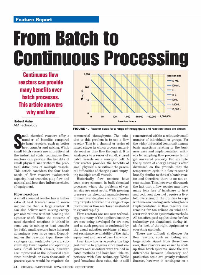
Small chemical reactors offer a
number of benefits compared
to large reactors, such as better
heat transfer and mixing. While
small batch vessels are impractical at
the industrial scale, continuous flow
reactors can provide the benefits of
small physical size without the prac-
tical difficulties of multiple vessels.
This article considers the four basic
needs of flow reactors (volumetric
capacity, heat transfer, plug flow and
mixing) and how they influence choice
of equipment.
Flow reactors
A small chemical reactor has a higher
ratio of heat transfer area to work-
ing volume than a large reactor. It
can also deliver more mixing energy
per unit volume without bending the
agitator shaft. Since the outcome of
most chemical reactions is linked in
some way to mixing or heat transfer
(or both), small reactors have inherent
advantages over large ones. Depend-
ing on the reaction type, these ad-
vantages can contribute toward sub-
stantially lower capital and operating
costs. Small batch vessels, however,
are impractical at the industrial scale
since hundreds or even thousands of
process cycles would be required for
commercial throughputs. The solu-
tion to this problem is to use a flow
reactor. This is a channel or series of
mixed stages in which process materi-
als react as they flow through it. It is
analogous to a series of small, stirred
batch vessels on a conveyor belt. A
flow reactor provides the benefits of
small physical size without the practi-
cal difficulties of charging and empty-
ing multiple small vessels.
Historically, flow reactors have
been more common in bulk chemical
processes where the problems of ves-
sel size are most acute. With growing
pressure on chemical manufacturers
to meet ever-tougher cost and regula-
tory targets however, the range of ap-
plications for flow reactors has started
to expand rapidly.
Flow reactors are not new technol-
ogy, but many of the applications they
are now being developed for are new,
and as such progress is confronted by
the usual adoption problems of mar-
ket resistance, availability of the right
equipment and lack of user knowhow.
User knowhow is arguably the big-
gest hurdle to progress since most en-
gineers and scientists were trained in
batch methods and have had little ex-
perience with flow technology. While
good knowhow does exist, this is still
concentrated within a relatively small
number of individuals or groups. For
the wider industrial community, many
basic questions relating to the busi-
ness case and implementation meth-
ods for adopting flow processes fail to
get answered properly. For example,
the question of energy saving is often
dismissed on the grounds that the
temperature cycle in a flow reactor is
broadly similar to that of a batch reac-
tor and therefore, there is no net en-
ergy saving. This, however, disregards
the fact that a flow reactor may have
many tons less of hardware to heat
and cool, and does not require a five-
fold oversizing of the utilities to cope
with uneven heating and cooling loads.
Implementation of flow reactors also
remains far too reliant on trial-and-
error rather than systematic methods.
All too often good applications for flow
technology get abandoned during tri-
als for lack of the right equipment or
operating methods.
There are difficult challenges for
flow reactors, such as fouling and
large solids. Apart from these how-
ever, flow reactors are easier to scale
up than batch systems, since the size
differences between laboratory and
production scale are greatly reduced.
Success, however, is contingent on a
Feature Report
34 CHEMICAL ENGINEERING WWW.CHE.COM OCTOBER 2012
Feature Report
Robert Ashe
AM Technology
Continuous flow
reactors can provide
many benefits over
batch processes.
This article answers
why and how
From Batch to Continuous Processing
0
10
100
1,000
0 10 100 1,000 10,000 100,000 1,000,000
Flo
w, L
/h
Reaction time, s
Reactor size
10 mL
100 mL
1 L
10 L
100 L
1,000 L
10,000 L
FIGURE 1. Reactor sizes for a range of throughputs and reaction times are shown

good understanding of the underlying
process characteristics and a broad
knowledge of reactor types to address
the specific needs.
Reasons for continuous The benefits of flow reactors vary ac-
cording to the nature of the process, but
they typically include the following:
• Improved yield and quality — For competitive and consecutive re-actions, flow reactors can deliver
significant improvements to yield and purity
• Reduced solvent use — For heat-transfer limited reactions, flow re-actors can operate with leaner re-
action mixtures and therefore with less solvent. Similarly, continuous countercurrent processes for opera-
tions, such as extraction, yield bet-ter separation with less solvent
• Capital cost — For mixing or heat-transfer limited processes, flow re-actors are smaller and often signifi-cantly smaller than batch reactors. Smaller physical size contributes to lower equipment costs as well as smaller utilities and buildings. Capi-tal expenditure reductions on build-ing costs alone for a continuous plant
can amount to 50% or more [1]
• Utility costs — Over 50% of the en-ergy used in a batch reactor is wasted
on the hardware, cross mixing be-tween the heating and cooling fluids
and uneven utility loads. Flow reac-tors can reduce this waste by 90% or more by virtue of reduced physical size and steady state operation
• Plant flexibility — Batch reactors have good flexibility in terms of the unit operations they can perform, but very limited flexibility in terms of working capacity. A flow reactor
is more specialized in terms of unit operations it can perform, but the capacity per cycle can be varied by
orders of magnitude by changing the cycle time. This can contribute to greater plant flexibility and there-fore less process equipment
• Safety costs — For hazardous pro-cesses, the cost of managing safety in small flow reactors is inherently cheaper than large batch reactors.
Small pressure vessels are cheaper to fabricate and require smaller emergency-relief systems
The extent to which these benefits apply depends on factors such as pro-
cess type, product value and through-
put. It also depends on whether the application is for an existing facility or a new one.
Manufacturers from the chemical process industries (CPI) often view the batch versus continuous ques-tion as an either/or option, and reject
flow reactors on the grounds that the
batch vessels are still required for work-up operations. While this may be true in many cases, the commer-cial advantages of using flow reac-
tors within existing batch processes should not be underestimated. Flow reactors generally occupy small foot-prints and can be integrated within
existing batch plants. Where flow re-actors can make a material difference to yield or reduction in batch fail-
ures, the commercial case for using them within existing batch processes can be self-evident. There are also
other reasons for using flow reactors
within existing batch processes, such as debottlenecking, reducing energy
waste, more efficient use of solvents, improved safety, reduced problems of bursting disc failure (which can dis-
able an entire production facility) and increasing plant flexibility.
Understanding the process While microreactors can be used suc-cessfully with very little process in-
formation, the same does not apply to larger flow reactors. Scaling up flow
reactors by trial-and-error is difficult
and potentially dangerous. A good un-
derstanding of the process is required before trials are undertaken.
A variety of analytical devices can be
used to study flow processes, but one
of the most useful tools for generating design data is a reaction calorimeter, since this provides information about both kinetics and heat of reaction. It is also worth noting that the differ-
ences between batch and flow reactors
relate to scale (there is no flow effect) and a small reaction calorimeter with similar heat transfer and mixing char-acteristics (to the proposed flow reac-
tor) can provide reliable design data for scaleup.
Even where processes are relatively
well understood however, there is no
substitute for testing under flow con-
ditions. The equipment used for scale-up development should be as similar as possible to the full sized reactor. This generally favors the use of large
flow reactors for scaleup work rather
than microreactors (other than where microreactors can be used at the pro-duction scale).
Reactor capacityThe volumetric capacity of a flow re-actor should be as small as possible. Apart from the obvious benefits of small footprint and higher perfor-mance, small flow reactors have proportionately lower startup and
shutdown losses. The physical size is calculated from the relationship:
Reactor size (L) = Throughput (L/s) ×
Reaction time (s)
Reactor sizes for a range of through-puts and reaction times are shown in Figure 1.
A flow reactor can be scaled up by
a process of numbering up (or scaling out). For this, the channel size is kept constant and capacity is increased by
using multiple parallel channels of similar size. The size of the scaled up system can be predicted accurately when numbering up, since the func-tional capabilities of the channels re-
main unchanged. The reactor can also be scaled up
by increasing the channel length, al-
though scope for this is limited by pressure drop. In some cases, longer channels will give better performance (due to higher velocities) and there-fore require smaller working capaci-ties than predicted.
Increasing the tube diameter is often the only practical way of scaling up,
especially where high reactor volumes are required. Increasing the diameter, however, often reduces performance, and therefore the scaled system may have to be larger than predicted to
compensate for the difference. When scaling up, it is preferable to
use the maximum tube diameter pos-sible, subject to satisfactory perfor-
mance. Short, large-diameter tubes have lower fabrication costs, a reduced
tendency to block and a lower pressure
drop. They are also easier to clean.
CHEMICAL ENGINEERING WWW.CHE.COM OCTOBER 2012 35
FIGURE 2. In plug � ow, the � uid velocity across the face of a channel is uniform
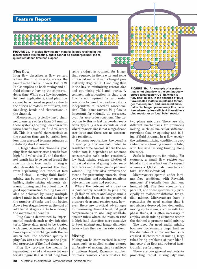
Feature Report
36 CHEMICAL ENGINEERING WWW.CHE.COM OCTOBER 2012
Plug flow Plug flow describes a flow pattern
where the fluid velocity across the
face of a channel is uniform (Figure 2).
It also implies no back mixing and all
fluid elements having the same resi-
dence time. While plug flow is required
for most applications, ideal plug flow
cannot be achieved in practice due to
the effects of molecular diffusion, sur-
face drag, bends and obstructions in
the channel.
Microreactors typically have chan-
nel diameters of less than 0.5 mm. In
these systems, the plug flow character-
istics benefit from low fluid velocities
[2]. This is a useful characteristic as
the reaction time can be varied from
less than a second to many minutes in
relatively short channels.
In larger diameter channels, good
plug-flow characteristics benefit from
high fluid velocities [2], and the chan-
nel length has to be varied to suit the
reaction time. Good radial mixing is
also desirable to prevent the fluid
from separating into zones of fast
— and slow — moving fluid. Radial
mixing can be achieved by means of
baffles, static mixing elements, dy-
namic mixing and turbulent flow. A
good approximation to plug flow can
also be achieved by using multiple
stirred tanks in series, and the higher
the number of tanks used the better.
Above ten stages, however, the cost of
additional stages starts to outweigh
the incremental benefits.
Plug flow is determined by experi-
mental methods such as dye injection
tests. These data need to be treated
with care, because the quality of plug
flow required will change with the re-
action rate. The observed quality of
plug flow can also change as the phys-
ical properties of the fluid changes.
Plug flow provides the means for
separating reacted and unreacted ma-
terial (Figure 3a). Without plug flow,
some product is retained for longer
than required in the reactor and some
unreacted material is discharged pre-
maturely (Figure 3b). Good plug flow
is the key to minimizing reactor size
and optimizing yield and purity. A
common misconception is that plug
flow is not required for zero order
reactions (where the reaction rate is
independent of reactant concentra-
tion). This is not correct. Plug flow is
important for virtually all processes,
even for zero order reactions. The ex-
ception to this is fast zero-order reac-
tions (typically a few seconds or less)
where reactor size is not a significant
cost issue and there are no consecu-
tive reactions.
For many applications, the benefits
of good plug flow are not limited to
residence time control. Where the re-
action rate is dependent on reactant
concentration (nth order reactions),
low back mixing reduces dilution of
unreacted material giving faster reac-
tion rates and higher yields per unit
volume. Plug flow also provides the
means for preventing material from
over reacting, and reducing reactions
between reactants and product.
Where the outcome of a reaction
is particularly sensitive to plug flow,
high fluid velocities and long channels
are desirable. From the perspective of
pressure drop and reactor cost, how-
ever, there are practical advantages
to minimizing channel length. A good
compromise is to use long small-di-
ameter tubes where the reaction rate
is high (and therefore more sensitive
to back mixing) and larger diameter
tubes where the reaction rate is slow.
Mixing Mixing can be characterized in many
ways, such as applied mixing energy,
uniformity of mixing, time to achieve
a uniform blend, Reynolds number
or mass transfer characteristics for
two phase mixtures. There are also
different mechanisms for promoting
mixing, such as molecular diffusion,
turbulent flow or splitting and fold-
ing of fluid streams. In a flow reactor,
the optimum mixing condition is good
radial mixing (mixing across the tube)
with low axial mixing (mixing along
the tube).
Scale is important for mixing. For
example, a small flow reactor can
blend a fluid in a fraction of a second,
whereas a 1,600-L batch reactor can
take 10 to 20 seconds [3].
Microreactors operate under lami-
nar flow conditions with Reynolds
numbers of typically less than one
hundred [4]. The flow streams are
parallel, and these systems rely prin-
cipally on molecular diffusion for ra-
dial mixing. Microreactors have a
reputation for good mixing that is
not always deserved. For demanding
mixing applications, such as with two
phase fluids, it is often necessary to
employ static mixing elements within
the channel to promote radial mixing.
The need for good radial mixing
becomes increasingly important as
the diameter of a flow reactor is in-
creased. Without radial mixing, large
tubes bring problems of poor blend-
ing, poor plug flow and reduced heat-
transfer performance.
There are two general methods for
promoting radial mixing: dynamic
FIGURE 3a. In a plug � ow reactor, material is only retained in the reactor while it is reacting, and it cannot be discharged until the re-quired residence time has elapsed
FIGURE 3b. An example of a system that is not plug � ow is the continuously stirred tank reactor (CSTR), which is fully back-mixed. In the absence of plug � ow, reacted material is retained for lon-ger than required, and unreacted mate-rial is discharged prematurely. It is there-fore inherently less efficient than either a plug reactor or an ideal batch reactor
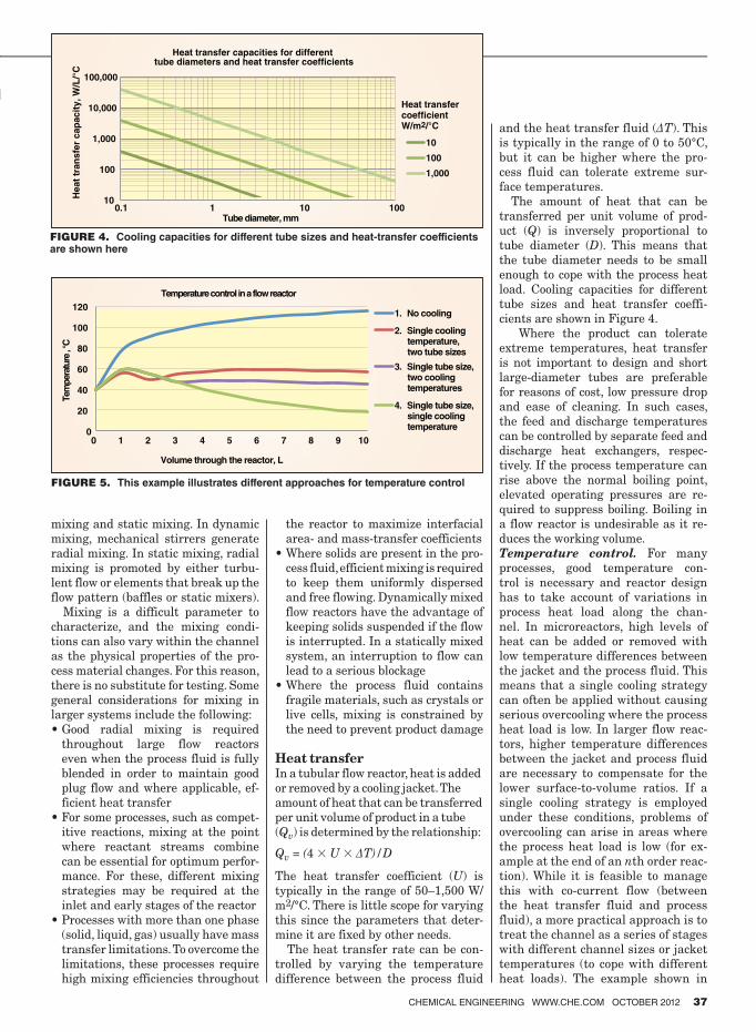
CHEMICAL ENGINEERING WWW.CHE.COM OCTOBER 2012 37
mixing and static mixing. In dynamic
mixing, mechanical stirrers generate
radial mixing. In static mixing, radial
mixing is promoted by either turbu-
lent flow or elements that break up the
flow pattern (baffles or static mixers).
Mixing is a difficult parameter to
characterize, and the mixing condi-
tions can also vary within the channel
as the physical properties of the pro-
cess material changes. For this reason,
there is no substitute for testing. Some
general considerations for mixing in
larger systems include the following:
• Good radial mixing is required throughout large flow reactors
even when the process fluid is fully
blended in order to maintain good
plug flow and where applicable, ef-
ficient heat transfer
• For some processes, such as compet-itive reactions, mixing at the point
where reactant streams combine
can be essential for optimum perfor-
mance. For these, different mixing
strategies may be required at the inlet and early stages of the reactor
• Processes with more than one phase (solid, liquid, gas) usually have mass transfer limitations. To overcome the
limitations, these processes require high mixing efficiencies throughout
the reactor to maximize interfacial
area- and mass-transfer coefficients
• Where solids are present in the pro-cess fluid, efficient mixing is required to keep them uniformly dispersed
and free flowing. Dynamically mixed
flow reactors have the advantage of
keeping solids suspended if the flow
is interrupted. In a statically mixed
system, an interruption to flow can
lead to a serious blockage
• Where the process fluid contains fragile materials, such as crystals or
live cells, mixing is constrained by
the need to prevent product damage
Heat transfer
In a tubular flow reactor, heat is added
or removed by a cooling jacket. The
amount of heat that can be transferred
per unit volume of product in a tube
(Qv) is determined by the relationship:
Qv = (4 × U × ∆T)/D
The heat transfer coefficient (U) is
typically in the range of 50–1,500 W/m2/°C. There is little scope for varying this since the parameters that deter-
mine it are fixed by other needs.
The heat transfer rate can be con-
trolled by varying the temperature
difference between the process fluid
and the heat transfer fluid (∆T). This
is typically in the range of 0 to 50°C, but it can be higher where the pro-
cess fluid can tolerate extreme sur-
face temperatures.
The amount of heat that can be
transferred per unit volume of prod-
uct (Q) is inversely proportional to
tube diameter (D). This means that
the tube diameter needs to be small
enough to cope with the process heat
load. Cooling capacities for different tube sizes and heat transfer coeffi-
cients are shown in Figure 4.
Where the product can tolerate extreme temperatures, heat transfer
is not important to design and short
large-diameter tubes are preferable
for reasons of cost, low pressure drop
and ease of cleaning. In such cases,
the feed and discharge temperatures
can be controlled by separate feed and
discharge heat exchangers, respec-
tively. If the process temperature can
rise above the normal boiling point,
elevated operating pressures are re-
quired to suppress boiling. Boiling in a flow reactor is undesirable as it re-
duces the working volume.
Temperature control. For many
processes, good temperature con-
trol is necessary and reactor design
has to take account of variations in
process heat load along the chan-
nel. In microreactors, high levels of
heat can be added or removed with
low temperature differences between
the jacket and the process fluid. This
means that a single cooling strategy
can often be applied without causing
serious overcooling where the process
heat load is low. In larger flow reac-
tors, higher temperature differences
between the jacket and process fluid
are necessary to compensate for the
lower surface-to-volume ratios. If a
single cooling strategy is employed
under these conditions, problems of
overcooling can arise in areas where
the process heat load is low (for ex-
ample at the end of an nth order reac-
tion). While it is feasible to manage this with co-current flow (between
the heat transfer fluid and process
fluid), a more practical approach is to
treat the channel as a series of stages
with different channel sizes or jacket
temperatures (to cope with different
heat loads). The example shown in
FIGURE 4. Cooling capacities for different tube sizes and heat-transfer coefficients are shown here
FIGURE 5. This example illustrates different approaches for temperature control
0
20
40
60
80
100
120
0 1 2 3 4 5 6 7 8 9 10
Tem
per
ature
, °C
Volume through the reactor, L
Temperature control in a flow reactor
1. No cooling
2. Single cooling temperature, two tube sizes
3. Single tube size, two cooling temperatures
4. Single tube size, single cooling temperature
10
100
1,000
10,000
100,000
0.1 1 10 100
Heat
tran
sfe
r cap
acit
y, W
/L/°
C
Tube diameter, mm
Heat transfer coefficientW/m2/°C
10
100
1,000
Heat transfer capacities for different tube diameters and heat transfer coefficients
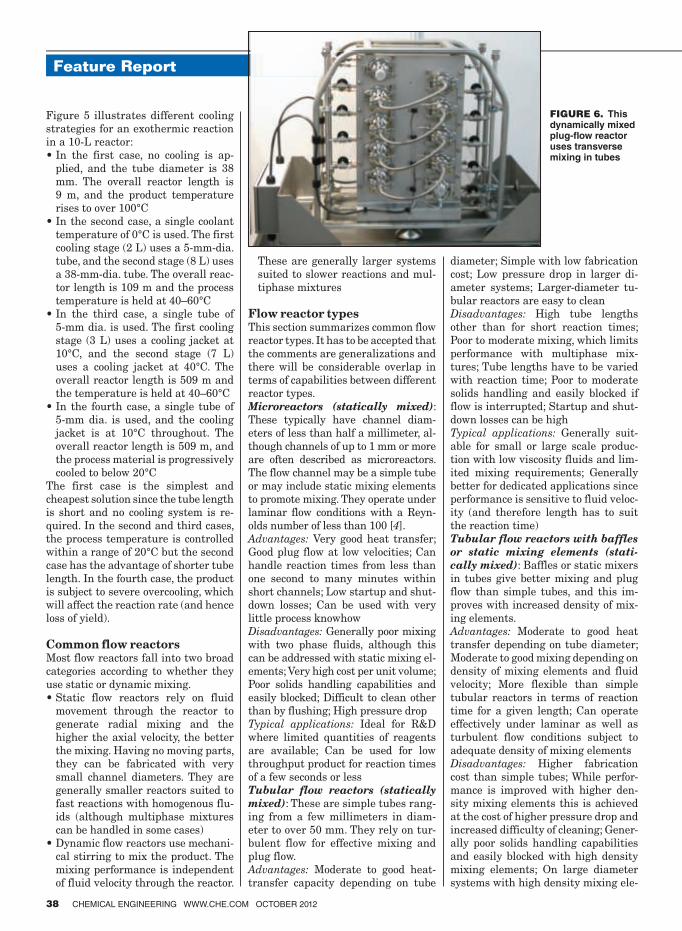
Feature Report
38 CHEMICAL ENGINEERING WWW.CHE.COM OCTOBER 2012
Figure 5 illustrates different cooling
strategies for an exothermic reaction
in a 10-L reactor:
• In the first case, no cooling is ap-plied, and the tube diameter is 38 mm. The overall reactor length is
9 m, and the product temperature rises to over 100°C
• In the second case, a single coolant temperature of 0°C is used. The first cooling stage (2 L) uses a 5-mm-dia.
tube, and the second stage (8 L) uses a 38-mm-dia. tube. The overall reac-tor length is 109 m and the process temperature is held at 40–60°C
• In the third case, a single tube of 5-mm dia. is used. The first cooling
stage (3 L) uses a cooling jacket at 10°C, and the second stage (7 L) uses a cooling jacket at 40°C. The overall reactor length is 509 m and
the temperature is held at 40–60°C • In the fourth case, a single tube of
5-mm dia. is used, and the cooling jacket is at 10°C throughout. The overall reactor length is 509 m, and the process material is progressively cooled to below 20°C
The first case is the simplest and cheapest solution since the tube length is short and no cooling system is re-quired. In the second and third cases, the process temperature is controlled within a range of 20°C but the second case has the advantage of shorter tube length. In the fourth case, the product is subject to severe overcooling, which will affect the reaction rate (and hence loss of yield).
Common flow reactorsMost flow reactors fall into two broad categories according to whether they use static or dynamic mixing. • Static flow reactors rely on fluid
movement through the reactor to
generate radial mixing and the
higher the axial velocity, the better the mixing. Having no moving parts, they can be fabricated with very small channel diameters. They are generally smaller reactors suited to fast reactions with homogenous flu-ids (although multiphase mixtures can be handled in some cases)
• Dynamic flow reactors use mechani-cal stirring to mix the product. The mixing performance is independent of fluid velocity through the reactor.
These are generally larger systems suited to slower reactions and mul-tiphase mixtures
Flow reactor typesThis section summarizes common flow reactor types. It has to be accepted that the comments are generalizations and
there will be considerable overlap in terms of capabilities between different reactor types. Microreactors (statically mixed):
These typically have channel diam-eters of less than half a millimeter, al-though channels of up to 1 mm or more are often described as microreactors. The flow channel may be a simple tube or may include static mixing elements to promote mixing. They operate under laminar flow conditions with a Reyn-olds number of less than 100 [4].
Advantages: Very good heat transfer; Good plug flow at low velocities; Can handle reaction times from less than
one second to many minutes within short channels; Low startup and shut-down losses; Can be used with very little process knowhowDisadvantages: Generally poor mixing with two phase fluids, although this can be addressed with static mixing el-ements; Very high cost per unit volume; Poor solids handling capabilities and easily blocked; Difficult to clean other than by flushing; High pressure drop Typical applications: Ideal for R&D where limited quantities of reagents are available; Can be used for low throughput product for reaction times of a few seconds or lessTubular flow reactors (statically
mixed): These are simple tubes rang-ing from a few millimeters in diam-eter to over 50 mm. They rely on tur-bulent flow for effective mixing and plug flow. Advantages: Moderate to good heat-
transfer capacity depending on tube
diameter; Simple with low fabrication cost; Low pressure drop in larger di-ameter systems; Larger-diameter tu-bular reactors are easy to clean Disadvantages: High tube lengths other than for short reaction times; Poor to moderate mixing, which limits performance with multiphase mix-tures; Tube lengths have to be varied with reaction time; Poor to moderate solids handling and easily blocked if flow is interrupted; Startup and shut-down losses can be highTypical applications: Generally suit-able for small or large scale produc-tion with low viscosity fluids and lim-ited mixing requirements; Generally better for dedicated applications since performance is sensitive to fluid veloc-ity (and therefore length has to suit the reaction time)
Tubular flow reactors with baffles
or static mixing elements (stati-
cally mixed): Baffles or static mixers
in tubes give better mixing and plug flow than simple tubes, and this im-proves with increased density of mix-ing elements.
Advantages: Moderate to good heat
transfer depending on tube diameter; Moderate to good mixing depending on density of mixing elements and fluid velocity; More flexible than simple tubular reactors in terms of reaction time for a given length; Can operate effectively under laminar as well as turbulent flow conditions subject to adequate density of mixing elements Disadvantages: Higher fabrication cost than simple tubes; While perfor-mance is improved with higher den-sity mixing elements this is achieved at the cost of higher pressure drop and increased difficulty of cleaning; Gener-ally poor solids handling capabilities and easily blocked with high density mixing elements; On large diameter systems with high density mixing ele-
FIGURE 6. This dynamically mixed plug-� ow reactor uses transverse mixing in tubes

CHEMICAL ENGINEERING WWW.CHE.COM OCTOBER 2012 39
ments, hot spots can occur at the cen-
ter of the tube
Typical applications: Suitable for a
broad range of manufacturing op-
erations, but preferably with clean
fluids; For reasons of cost and pres-
sure drop, generally better suited to
reaction times of a few minutes or
less; Given the practical difficulties
of cleaning, generally better for ded-
icated applications
Oscillatory flow reactors (stati-
cally mixed): In static flow reactors,
mixing relies on axial movement of
fluid through the channel. The pen-
alty for this is high tube length and
high pressure drop for processes with
long reaction times. The oscillatory
flow reactor addresses this problem
using bidirectional flow. This gives
higher average velocities in short,
larger diameter tubes even with long
reaction times.
Advantages: Significant reduction
in overall length compared to other
static flow reactors; Better solids
handling characteristics than other
static flow reactors; Moderate to good
mixing; Generally more flexible than
other static flow reactors in terms of
residence time
Disadvantages: The additional vari-
able of oscillatory flow makes charac-
terization more difficult; Accumula-
tion of gas or vapor in the reactor can
severely impair mixing performance;
Performance is a trade off between
good mixing (which favors short tubes)
and good plug flow (which favors long
tubes); An additional pump is required
for the oscillatory flow; This has to
generate relatively high pressures
and can present material selection
problems with some process fluids
Typical applications: Suited to a broad
range of slower reactions and can han-
dle slurries
Single, continuously stirred-tank
reactor (dynamically mixed): This
is a conventional stirred tank with
continuous feed and discharge. This
is not a plug flow reactor, which se-
verely limits its suitability for most
applications.
Advantages: Good mixing that is inde-
pendent of fluid velocity through the
reactor; Good solids handling; Very
low pressure drop (gravity transfer
can often be used)
Disadvantages: Poor performance for
most applications due to the lack of
plug flow; Significant oversizing is re-
quired to compensate for the high level
of reacted material retained in the re-
actor; Moderate to poor heat transfer
capacity depending on size
Typical applications: Only a small
number of applications suit this type of
reactor. These are generally zero order
processes where reactor size is not a
significant cost factor and there are no
consecutive or competitive reactions
Multiple, continuously stirred-
tank reactors in series (dynami-
cally mixed): The lack of plug flow in
a single-stage stirred tank can be over-
come by using multiple stirred tanks
in series. While as few as three tanks
in series have been employed by some
users, a substantial improvement in
plug flow (in terms of residence time
distribution) is observed by using ten
stages [5]. Above ten stages, the trade-
off between cost and performance be-
comes increasingly difficult to justify.
For very small systems, agitated cell
reactors that employ transverse mix-
ing can be used. For larger systems,
conventional tanks with rotational
stirrers can be used.
Advantages: Good mixing that is inde-
pendent of fluid velocity through the
reactor; Good solids handling; Very
low pressure drop (gravity transfer
can often be used)
Disadvantages: Small systems are
expensive due to the high number of
stirred stages required for optimum
performance; Large systems suffer
from the same heat-transfer and
mixing limitations of conventional
batch reactors
Typical applications: Process devel-
opment with multi-phase mixtures;
At the industrial scale, they are more
common where volumetric capacities
of thousands of liters are required
Dynamically mixed plug-flow re-
actors: Plug flow reactors need to be
long and tubular to achieve good plug
flow. While rotating stirrers can be
designed for use in tubes, they gen-
erally present significant cost and
fabrication problems. An alternative
design for agitated tube reactors uses
transverse mixing with free-moving
agitator elements (Figure 6). These
generate strong radial mixing in long
tubes without the cost and technical
problems associated with mechanical
seals, baffles and shaft stability.
Advantages: Good mixing that is in-
dependent of fluid velocity through
the reactor; Good plug flow; High flex-
ibility in terms of reaction time range
for a given tube length; Short, large
diameter tubes that are easy to clean;
Good handling characteristics for
multi-phase mixtures. Very low pres-
sure drop (gravity transfer can often
be used)
Disadvantages: Subject to minimum
diameter constraints, which limits the
scope for strong exotherms where good
temperature control is required
Typical applications: Processes with
long reaction times, slurries and gas-
liquid mixtures
Conclusion
The batch to continuous debate en-
compasses a broad spectrum of views.
At one extreme are those who remain
fully committed to batch methods. For
some applications batch reactors are
clearly a better solution or the only op-
tion. Processes with sticky materials
for example are inherently unsuited
to flow systems as are some slurries
with large solids. In the absence of
heat transfer or mixing constraints,
batch reactors are also cheaper than
flow reactors (although significantly
less energy efficient). The resistance
to change from batch to continuous
is often justified on the grounds that
existing batch processes are well op-
timized and offer little scope for im-
provement. This is true for some pro-
cesses and particularly so when the
cost of switching from batch to con-
tinuous is factored in.
Where there are mixing or heat
transfer constraints however, the com-
mercial benefits of flow reactors are
often clear cut and compelling. It has
been suggested that as much as 60%
of commercially important non-poly-
mer reactions could be run more effi-
ciently in flow reactors [6] (and higher
if peripheral benefits are included). To
quantify these benefits, however, ac-
count needs to be taken of many fac-
tors that contribute to lower cost of
goods. It also has to be recognized that
most processes in use today were de-
veloped for batch reactors and would
Feature Report
40 CHEMICAL ENGINEERING WWW.CHE.COM OCTOBER 2012
not necessarily be the first choice of
method given the option of more-capa-
ble flow reactors.
At the other extreme of the batch
to continuous debate are advocates
of fully continuous processes where
multiple steps are carried out within
a single process train. The difficulty
here is that good residence-time con-
trol is critical to many flow processes.
Problems in one stage of a continuous
process will impact the entire process
train, and the system will only be as
good as the least reliable step. As pro-
cess equipment and knowhow develop
in this field, the scope for integrating
multiple steps will improve, but as
things stand, multi-step continuous
processes will remain the exception
rather than the rule.
The near term future for chemical
process technology must lie between
the extremes of fully batch and fully
continuous [7]. There are many com-
mon processes where incumbent
methods are severely constrained by
heat transfer and mixing limitations.
Integrating flow reactors within exist-
ing batch processes for the right ap-
plications will contribute to: smaller
equipment, greater plant flexibility,
fewer batch failures, improved yield/
quality, improved safety, lower energy
costs and reduced solvent use. Prog-
ress in this area, however, will depend
on a broader understanding of the
subject in terms of methods for iden-
tifying suitable applications for flow
reactors, a better knowledge of the
available equipment and systematic
methods for process development. ■ Edited by Dorothy Lozowski
Author
Robert Ashe (AM Technology, The Heath Business & Tech-nical Park, Runcorn,Cheshire, WA7 4QX, U.K.; Phone: +44 (0) 1928.515454; Email: [email protected]) is a chemical engineer with over 35 years of experience in fine chemicals, pharmaceuti-cals and food manufacturing. Much of his career has been devoted to chemical plant de-
sign in high-value chemical manufacturing. In 2000, he co-founded AM Technology with David Morris. This company specializes in the manu-facture of flow reactors and holds a broad portfo-lio of patents for dynamic mixing in tubes.
Circle 1 on p. 60 or go to adlinks.che.com/40272-01
References
1. Nichols, J., Innovations in Process Technol-ogy for Manufacture of APIs and BCPs, Pharm. Eng., Vol. 28, No 5, Sept./Oct. 2008.
2. Levenspiel, O., Bischoff, K., “Backmixing in the Design of Chemical Reactors” Vol. 51, Dec. 1959.
3. Eslinger, J., De Dietrich Process Systems, Bulletin BP 8, F-61170, Sept. 28, 2004.
4. Capretto L. and others, “Micromixing Within Microfluidic Devices, Topics in Current Chemistry”, Vol. 304, pp. 27–68, 2011.
5. Levenspiel, O., “Chemical Reaction Engineer-ing”, 2nd Ed., John Wiley and Sons, 1972.
6. Calabrese, G.S. and Pissavini, S., From batch to continuous flow processing in chemicals manufacturing, AIChE J., Vol. 57, No. 4, pp. 828–834, 2011.
7. Roberge, D.M. and others, Microreactor Tech-nology and Continuous processes in the fine chemical and pharmaceutical Industry: is the Revolution Underway?, OPRD, Vol. 12, pp. 905–910, 2008.

Blending and segregation are
two opposite and competing
processes in solids handling
that ideally fit the expres-
sion “two sides of the same coin.” But,
if you think about it, coins have three
sides and sampling completes the idi-
omatic expression perfectly. Blending
is a necessary and essential process
operation widely employed in many
industries and materials, from nano-
scale powders to run-of-mine ores.
Segregation is almost always an un-
wanted consequence of handling op-
erations that reverses the blending
process or creates a need for blending
where it might not otherwise be nec-
essary if it were not for the effects of
segregation. Sampling is the vitally
important tool for measuring and
quantifying a blend, understanding
the sources and effects of segregation
and for troubleshooting problems.
BlendingBlending is the process of combining
two or more materials to achieve a
combined product. The mixture may
be a combination of dissimilar materi-
als such as cement, sand and aggre-
gate to make concrete; or cereal flakes,
raisins, nuts and marshmallows to
make breakfast cereal. A blend may
also be a combination of chemically
similar particles blended to create a
uniform mixture of particle sizes, or
another property such as color, flavor,
melt index and so on. Blend-
ing bulk solids can be achieved
in many ways including batch
and continuous methods and
with a wide variety of equip-
ment, covering the range from
extremely low intensity blend-
ing with gravity recirculation
or layering components onto a
belt, to high intensity blending
with high-speed, high specific-
horsepower blenders.
All of the various equipment
and processes for blending sol-
ids rely on three principal mechanisms
for achieving a blend: convection, dif-
fusion and shear.
Convection. Convection is the trans-
fer of a collection of particles from one
location to another. This can occur as a
result of material cascading in a tum-
ble blender, material moving against
the blade of a ribbon or paddle blender
or as a result of gas pressure pulses in
a pneumatic blender.
Diffusion. Diffusion is the random
redistribution of particles that occurs
as a result of increased particle mobil-
ity. Increased mobility typically occurs
when the bulk density of the material
is decreased sufficiently to allow in-
dividual particles to move relative to
one another. Fluidization in fluidized
bed reactors or granulators results in
diffusion. Mechanical blenders move
collections of particles by convection,
but when the speed of the agitator is
sufficient to locally fluidize material,
diffusion occurs. Tumble blenders,
continuous screw blenders and agi-
tated blenders also provide opportu-
nities for diffusion where material is
cascading or in free-fall.
Shear. The definition of shear as it
applies to solids blending is some-
times misunderstood. Shear occurs in
a flowing granular solid as a result of
a velocity gradient, and can develop
as either a discontinuous shear (for
instance, a shear or slip plane) or as
a continuous gradient of velocity. In
either case there can be some over-
lap in what could be called shear and
what might be characterized as con-
vection. The important difference, at
least as it applies to solids blending,
is in the intensity. Shear planes that
develop in gravity blending or in a
tumble blender or screw blender will
achieve blending predominantly by a
Solids Processing
Blending, Sampling and Segregation
These aspects of dry solids mixing
represent three sides of the same coin.
Do not discount them
Thomas G. Troxel
Jenike & Johanson, Inc.
CHEMICAL ENGINEERING WWW.CHE.COM OCTOBER 2012 41
Solids Processing
FIGURE 1. This pattern shows how the faster velocity in the center displaces material relative to the slower material at the walls

42 CHEMICAL ENGINEERING WWW.CHE.COM OCTOBER 2012
Solids Processing
convective process. Shear in a high-
speed mixer will have a different end
result in that it will be much more
effective in breaking up agglomer-
ates of fine powders and distribut-
ing small-particle-size material with
high surface activity.
Figure 1 is a cross section view
through a bin showing the displace-
ment of material as it flows. The pat-
tern shows how the faster velocity in
the center displaces material relative
to the slower material at the walls.
This displacement pattern can be
described as shear deformation, but
the blending that occurs is caused by
convection of collections of material
from the central part of the bin that
reach the outlet sooner than material
near the wall. If material withdrawn
from the bin is circulated back to the
top, the discreet fill pattern that was
placed into the bin will be smeared
and homogenized, and some degree of
blending will be achieved after several
recirculations [1].
In a high-speed agitated blender,
shear occurs with significantly higher
intensity near the agitator but affects
a relatively small volume of material.
The high-intensity shear can break
agglomerates, plate fine particles onto
the surface of larger particles and re-
distribute particles with much higher
intensity, causing better diffusion of
small particles that may adhere to
themselves or other particles. Ideally,
the convective component of blending
in this type of blender brings all of the
material in the blender into the high
shear zones.
Blend qualityIn casual conversation, terms such as
“uniform blend”, “homogenous mix-
ture”, and “well blended” are often
used without quantifying what they
mean. In the heavily scrutinized phar-
maceutical industry, regulations and
guidelines dictate specific and often
rigorous methodology for quantifying
the uniformity of a mixture. Food and
other consumer products must also
meet trade regulations for delivering
the stated quantity of product and
composition of ingredients. Quantify-
ing the structure of a blend requires
defining not only the composition (for
instance, the proportion of each com-
ponent and allowable
variation) but also the
quantity of material
that is to be measured.
The compositional re-
quirement of a blend
is usually well known
because it is either the
entire objective of the
process to produce a
particular mixture, such
as a pharmaceutical
tablet or box of cereal,
or it is an intermediate
mixture that has well
defined requirements. Determining
the amount of material to measure is
sometimes less clear, and may be dif-
ferent depending on who is answering
the question. In pharmaceutical ap-
plications the answer is clear in that
it is almost always based on the unit
dose of the blend that makes up the
final tablet.
In other applications the sample
size subjected to scrutiny is not as
clear cut. Take, for example, a box
of cereal. In one specific example a
manufacturer produced a cereal with
a cereal particle and a marshmallow
candy particle. The packaging line
filled boxes from a series of conveyors
that fed a mixture of the two compo-
nents into a gravimetric packaging
machine that dispensed the required
weight of the blend into each package.
The two components of the mixture
were of similar size and density and
the only blending that occurred was
in the handling system along several
conveyors and in a surge hopper. Each
component was metered onto the con-
veyor system at the correct ratio, but
there was not a discreet blending pro-
cess. The manufacturing plants fine
tuned their systems to get an accept-
able mixture into each box.
In this case, each box was always
within weight tolerance for the stated
package quantity, but there was no
direct control of the ratio of the two
components in any box. In an effort to
improve quality, a new packaging line
was installed that handled each com-
ponent individually up to the packag-
ing head where each component was
weighed in a series of weigh hoppers,
and then each box was filled from
several hoppers of each component,
selected by the packaging system
controller, to control both the propor-
tion of each component and the total
weight in a box. This would seem an
ideal solution since it would guaran-
tee both accurate package weight and
composition. From the producers point
of view, they had improved quality by
insuring that every package met their
quality standard.
However, to everyone’s surprise,
consumer complaints from packages
produced at this plant went up. What
the plant had gained in compositional
accuracy they had sacrificed in unifor-
mity. Consumers found that individual
bowls of cereal poured from the new
packages had much wider variations of
the two components than boxes filled
from the old filling line. The new fill-
ing line had given up control of blend-
ing, even though the blending in the
old system was very “low tech”. The
new system allowed only about one
second from the time the ingredients
were separate until they were com-
bined in the package. There was very
little opportunity to do any blending,
and the result was that some boxes
were well blended while others were
segregated. From the manufacturers
point of view, they had “improved qual-
ity” and were taking responsibility for
what they could control to the highest
degree of precision, but they were not
controlling the sample size of interest
to consumers.
Random blend. The simplified case
of blending two different ingredients
that do not have significant bonding
or other interactions is often referred
to as a random blend. In a random
blend, all individual particles are free
to move relative to each other, and
FIGURE 2. Sifting segregation occurs when a mixture containing a range of particle sizes is allowed to form a pile. Smaller particles sift between larger particles as each layer of material slides along the pile surface

CHEMICAL ENGINEERING WWW.CHE.COM OCTOBER 2012 43
particle bonding is very weak or does
not occur. Particles that form random
blends can be easy to blend, because
the particles move easily relative to
one another, but that also means that
they can readily separate from each
other and collect in zones of similar
particles when forces such as gravity,
airflow, or vibration act on the blend.
This process is referred to as segrega-
tion. Random blends are never perfect,
and even in the best-blended state
there will be random variations in
concentrations of components.
Ideal random blends are uncommon
in most industrial applications, al-
though the cereal example described
above comes close. In most dry blend-
ing applications, particles have some
tendency to interact with one another
by way of chemical, molecular, physi-
cal, or other means such that individ-
ual particles can agglomerate, coat or
bond to one another. When particle
interaction occurs, the blend is re-
ferred to as an ordered, structured, or
interactive blend. In an ideal world,
this type of blending process could
create new particles, each consisting
of the combined individual ingredi-
ents. A perfect particle created in this
blender would consist of the desired
ratio of each ingredient. This concept
of combining ingredients to create
new, chemically homogeneous parti-
cles is one of the primary objectives of
wet and dry granulation processes. In
most industrial blending processes,
the reality is somewhere between a
random blend and an ordered blend.
Some particles of the blend may have
very little tendency to interact while
other blend components may have
significant interaction.
SegregationSegregation is the separation of par-
ticles that have identifiable differ-
ences. By definition, identical parti-
cles cannot segregate. Segregation can
be driven by many forces including
gravity, electrostatic forces, fluid drag
forces and elastic forces.
Sifting. The most prevalent type of
segregation is sifting, which results
in separation by particle size. Sift-
ing segregation occurs to some de-
gree in virtually every industry that
handles bulk solids. Sifting will occur
in mixtures of different size particles
when particles are sufficiently large
so that surface forces are weak
relative to gravity (usually larger
than 100 microns), when particles
have mobility relative to one another
(in other words, they do not adhere to
each other) and when there is some
mechanism to allow particles to move
relative to one another. Collections of
different size particles will not spon-
taneously segregate when at rest, but
will often readily segregate when al-
lowed to move in many common, in-
dustrial handling processes.
Figure 2 shows an example of sift-
ing segregation that occurs when a
mixture containing a range of particle
sizes is allowed to form a pile. Smaller
particles sift between larger particles
as each layer of material slides along
the pile surface. As the pile builds up,
the finer fraction deposits preferen-
tially near the center and coarser frac-
tion near the edges.
A blend of perfect structured par-
ticles of identical size will not segre-
gate after discharge from the blender.
However, if there are size differences
between the particles, then segrega-
tion by size may occur. Even if all the
particles are chemically homogeneous,
this segregation may cause problems
because it may affect other blend prop-
erties, such as solubility or bulk den-
sity. There are many examples where
this type of segregation is important,
such as with spray-dried laundry de-
tergent and food products, and other
natural materials such as clay cat lit-
ter, coal and other mineral materials.
In these examples the particles vary
in size, but are virtually identical from
a chemical standpoint.
In many other industrial-blending
applications, particles not only dif-
fer in size, but also in chemical com-
position. And in most cases, particles
of different size also have different
chemical composition, so sifting seg-
regation not only results in physical
FIGURE 3. In the example described in the box on p. 44, cy-lindrical pellets with a nominal size of about 3 mm were being blended with nearly spherical beads with a size range from about 1 mm down to 150 microns
0.0
5.0
10.0
15.0
20.0
25.0
30.0
0 20 40 60 80 100
% B
ea
ds
Material emptied, %
Discharge from V blender
FIGURE 4. Implementation of a more-rigorous sampling method in the example on p. 44, revealed inadequate blending. Area between dotted lines represents desired blend ratio
FIGURE 5. Based on the improved sampling results, the example blender was modi� ed to improve the blending performance and minimize segregation mechanisms

44 CHEMICAL ENGINEERING WWW.CHE.COM OCTOBER 2012
property differences associated with
size distribution, such as bulk density
and fluidization behavior, but also dif-
ferences in chemical composition.
Fluidization segregation and
particle entrainment. Other com-
mon mechanisms of segregation that
act primarily on particle size are flu-
idization segregation and particle
entrainment or dusting segregation.
Fluidization segregation occurs where
gas movement through a bed of solids
causes finer, lighter particles to rise to
the top surface of a fluidized blend of
powder, while the larger, heavier par-
ticles concentrate at the bottom of the
bed. Particle entrainment or dusting
segregation occurs when fine particles
in a blend are carried by air currents
(such as during transfer of a blend
into a container) and then settle pref-
erentially at the container walls.
SamplingSampling is essential in determining the
state of the blend in a blender, in down-
stream equipment or in the final deliv-
ered product. Samples are analyzed to
measure the variables of interest to the
application, such as particle size, chemi-
cal composition, pH, dissolution rate,
color and so on. The overall average of
the sample results represents the aver-
age composition of the blend. Variations
between samples provide a measure of
blend uniformity. Variability can be ex-
pressed by statistical measures, such as
standard deviation, coefficient of varia-
tion, or relative standard deviation, as
well as other measures [2].
The single most important rule of
sampling is to collect a sample that
accurately represents the state of the
blend at the point where it is sampled.
In many industrial processes this is a
significant challenge due to either the
difficulty of getting a sample at the de-
sired location or because of the potential
for sampling error that is introduced by
the sampling method. The two “golden
rules” of sampling are to always collect
a full stream sample, and always collect
a sample while it is moving [3].
In the case of the cereal example
given above, sampling is easy because
the sample is either a whole box of ce-
real or individual servings poured from
the box. In either case the sample is
easy to get and it is possible to analyze
the entire sample. For other processes,
significant challenges can prevent
the use of good sampling techniques.
In an example involving limestone
AN EXAMPLE
0
5
10
15
20
25
30
0 20 40 60 80 100
% B
ea
ds
Material emptied, %
Optimized Blensert blender FIGURE 6. The sampling results for the new blender design show the improved perfor-mance. Area be-tween dotted lines represents desired blend ratio
In an example involving plastic compounding, engineers for the project had experience using a V-type rotating blender for simi-lar materials at other plants. Batch ingredients would be fed into
a scale hopper and then discharged into the blender. The blended batch would then be discharged into a surge bin feeding an ex-truder. While this process had worked successfully at other com-pounding plants, this plant would blend ingredients with a wider size range. The most extreme case involved blending the two ma-terials shown in Figure 3, which consisted of cylindrical pellets with a nominal size of about 3 mm and nearly spherical beads with a size range from about 1mm down to 150 microns.
Engineers for the project ran tests in a small-scale V-blender and evaluated blend uniformity by taking samples from the blender. The overall blend results showed a lot of scatter. Some samples were acceptable, while others were significantly outside the de-sired blend ratio. Engineers also noticed that when the batch was discharged after a test, the material in the receiving container was severely segregated. This prompted development of a more rigorous sampling method that included collecting samples from the discharge of the blender from beginning to end. When this was done the results, shown in Figure 4, clearly showed inad-equate blending. Based on this realization, further testing was done to determine if a tumbling type of blender could be used. After a series of trials, a cylindrical blend vessel with an conical hopper and insert was found to produce a blend within specifica-tion, and discharge a blended stream to the downstream vessel.
This example illustrates several key points about blending, seg-regation and sampling. First, the blender must provide the cor-rect blending action for the solids. These two materials are very
free flowing and hence blend easily. Blend time in the tumbling type blender is very short, on the order of tens of revolutions. However, the other side of the coin is equally important because the material also segregates readily, so maintaining the material in a blended state is difficult. This required two modifications to the geometry of the blend container. First, the dead zone near the center of the blender had to be reduced because the blender geometry did not allow enough diffusion to mix material in the center of the blender. Convection dominated the action in the blender, and diffusion occurred on the cascading surfaces, but some material remained poorly blended in the center. In addition to the blending performance, the flow pattern that developed dur-ing discharge had to be changed from funnel flow, where some of the blend remained stagnant during discharge, to mass flow, where all of the blend flowed as it discharged. In funnel flow, the highly segregating material could de-mix along shear surfaces during discharge. A mass flow pattern was achieved by design-ing a sufficiently steep hopper-shaped blend container with an internal bullet to displace material in the center of the container. The final configuration of the blender, shown in Figure 5, pro-duced the results shown in Figure 6.
The other important point illustrated in this example is sampling. Without sampling the blender discharge stream from start to fin-ish, it would be impossible to know if the blend delivered to the extruder would be uniform and within specification.
A blending process shouldn’t be considered as an independent step in a block diagram, but really must be treated as a synergy of the mixing activity, segregation and sampling to produce the desired end result. ❑
Solids Processing
CHEMICAL ENGINEERING WWW.CHE.COM OCTOBER 2012 45
at a circulating fluidized-bed boiler,
the size distribution of the limestone
used for fluegas desulfurization came
into question. This became a critically
important question because the plant
could not meet emission regulations
above about 50% output, and the blame
was falling on the size distribution of
the limestone produced by the onsite
preparation plant. The plant produced
about 50 ton/h of limestone, and to get
a meaningful sample was not a trivial
task. To satisfy all parties involved, the
plant had to modify its chute systems
to put in large diverter gates and posi-
tion several operators to coordinate the
collection of simultaneous full-stream
samples in 55-gal drum quantities.
Samples of this size pose another
challenge in analysis. Usually it is not
practical or convenient to analyze such
large sample quantities, so samples
must be reduced or split. Simply grab-
bing a small sample from a large sample
container can introduce significant sam-
pling error, especially if sifting segrega-
tion can occur. The preferred method of
splitting samples is to use a spin riffler,
which can divide a sample into a num-
ber of smaller splits, usually from 6 to
16 divisions. Spin rifflers are capable of
providing a high degree of uniformity
between the individual sub-samples.
Another challenging task is sampling
from a static bed in a blender. Clearly
these samples cannot be collected while
the material is moving, so some means
of getting a meaningful sample must
be used. Simply scooping material from
the top surface is insufficient for many
reasons, including particle segrega-
tion, which could make the top surface
significantly different from material
deeper in the bed. A sampling thief is
often used to collect samples from a sta-
tionary bed.
A sampling thief is a probe that can
be inserted into a bed of material to col-
lect a sample from below the surface.
Many designs exist, but in their basic
form, they consist of a rod, frequently
with a pointed tip. The rod has cavi-
ties cut into it along its length which
are covered by a tube that fits closely
over the rod and has openings that cor-
respond to the cavities in the rod. The
tube can be rotated to cover the cavities
or open them. When the rod is inserted
into the bed of material, and the tube
rotated to exposed the cavities, blended
material will fill the cavities, which can
then be covered again and withdrawn.
Thief sampling has been used exten-
sively and studied thoroughly. While it
remains the only practical way to collect
samples from all positions in a static
bed, it has been shown to have biases
and limitations that can cause sampling
error. These can come from properties of
the blend and from operator technique.
Some typical sources of error include
local segregation as material fills the
cavities, smearing as the thief is in-
serted into the bed, and preferential ad-
hesion or repulsion of some components
of the blend.
Sampling will always introduce
• ZERO CORROSION(unlike stainless and alloys)
• ZERO CONTAMINATION(unlike stainless and alloys)
• ZERO CHEMICAL ABSORPTION OR WICKING(unlike fiberglass reinforced plastics)
• ZERO TEARING, CRACKING, OR PEELING(unlike plastic linings)
• ZERO OR NEAR-ZERO ABRASION(unlike stainless, alloys, and fiberglass)
Vanton solid thermoplastic pumps to stainless, high alloy, plastic-lined and fiberglass pumps for water,
wastewater and corrosive treatment chemicals:
Vanton molds all wet end components ofsolid, homogeneous thermoplastics thatare 100% inert to the caustic and acidictreatment chemicals you handle, such as alum, ferric chloride, hydrofluosilicicacid, polymer, sodium hydroxide, sodiumhypochloride, sulfuric acid and others.
All wet end components of Vantoncentrifugal pumps are molded of solid PVC,PP or PVDF, and handle flows to 1450 gpm(330 m3/h), heads to 400 ft (122 m) andtemperatures to 275°F (135°C).
SUMP-GARD® Vertical
Centrifugal Pumps
Standard, bearingless,
low headroom, wash
down, integral motor/
shaft and vortex
CHEM-GARD® Horizontal
Centrifugal Pumps
Standard, ANSI, DIN,
mag drive, close coupled
and self priming
FLEX-I-LINER® Rotary
Peristaltic Pumps
Dosing/feeding liquids
and viscous fluids
to 6000 SSU
Non-metallic
Pump/Tank Systems
Tanks from 60 to 5000 gal
(227 to 18,900 liter) with
pumps and automated
controls
It means you can say good-bye to pumping problems you nowexperience with chemical transfer,disinfection, dosing, effluentcollection, lift stations, odor control,recirculation and other processapplications.
1-908-688-4216 [email protected]
Z-0
551
Circle 23 on p. 60 or go to adlinks.che.com/40272-23

Solids Processing
some degree of error, which can affect
the sampling results in three ways.
Perhaps the most common effect is
that sampling increases the variability
of samples, which produces data show-
ing that the uniformity of the blend is
worse than it actually is. In some cases,
this presumed “fact” is used to suggest
that a blend is actually better than
what the sampling data shows.
Sampling error can also produce
bias, or an overall shift in the results,
indicating that the measured average
from the collected samples is higher
or lower than the known blend com-
position. This type of error can be con-
founding because people often jump
to the conclusion that there is “miss-
ing” or “extra” material, somehow.
It is more likely that one component
adheres to, or is repelled by, the thief,
or preferential flow of one component
into the thief shifts the sample com-
position. Another possibility is that
a sample is collected from an inap-
propriate location, such as a known
dead zone in the blender that may be
holding the “missing” material. When
this type of error is observed it usually
requires additional detective work to
determine the cause of the bias.
Sampling devices can also produce
samples that show lower variabil-
ity than are actually present due to
smearing of the sample. This type of
error is often referred to as “counter-
feiting.” Counterfeiting is hard to de-
tect because it may produce results
that show blending is good.
The purpose of sampling is to ac-
curately quantify the state of a blend
or uncover blend quality issues, not to
mask or overlook suspected problems.
Samples should be intentionally col-
lected from suspected regions where
the blend may be less uniform, not just
from the middle of the blender, or dur-
ing the “best” part of a production run.
Fringe regions may include the surface
of the material, regions where the ma-
terial may have been stagnant during
blending and at the beginning and end
of discharge from a batch bin. ■Edited by Rebekkah Marshall
References
1. Carson, J.W., and Royal, T.A., Techniques of in-bin blending, IMechE, C418/056, 1991.
2. Fan, L.T., Chen, S.J., and Watson, C.A. Solids mixing. Industrial Eng. Chem. 62, 53–69, July 1970.
Author
Thomas G. Troxel is a vice president at Jenike & Johan-son, Inc. (3485 Empresa Dr., San Luis Obispo, CA 93401; Phone: 805-541-0901; Email: [email protected]). He holds a B.S. in Engineering Science (ES) from California Polytech-nic State University (Cal Poly) in San Luis Obispo. After graduating as the Outstand-ing Senior in the ES program
in 1981, he worked at General Dynamics Co. He then helped to open Jenike & Johanson’s San Luis Obispo, California facility in 1982. Troxel has been intimately involved in many aspects of the firm’s consulting and research activities on a wide range of projects including flow properties testing, modeling, blending, pneumatic convey-ing and fluidization. He has been a major force behind the firm’s expansion in mechanical design engineering and custom-built equipment.
Circle 10 on p. 60 or go to adlinks.che.com/40272-10

Vacuum conditions for many
unit operations — including
distillation, evaporation, dry-
ing, crystallization, filtration
and more — are typically achieved
using the following three approaches:
•Steamejectorsystems•Mechanicalvacuumpumps•Integrated vacuum systems (whichcombine steam ejectors and me-
chanical vacuum pumps)
This article is the second part of a
two-part series,1 and provides practi-
cal guidance for addressing — during
design and operation — some of the
most commonly encountered hazards
and maximizing the overall safety of
these systems.
This section reviews the potential
hazards that can occur with process
vacuum pumps and systems. These
include chemical sources of hazards,
explosion-related hazards and physi-
cal sources of hazards. They are dis-
cussed below, and are based on mate-
rial in Reference 1.
Chemical sources of hazardsChemical reactions and explo-
sions. All possible chemical reactions
that a vacuum system might encoun-
ter at any point in mechanical vacuum
pump systems should be considered —
particularly those that could result in
afireorexplosion(deflagration).Andsuch an analysis should consider these
scenarios during normal use, potential
misuse and failure conditions.
For instance, experience has shown
that explosions have occurred in situ-
ations involving materials that were
not originally considered by the sys-
tem designer, and in which the failure
mode of that particular scenario had
not been taken into account. During
this analysis, the reactions that should
be considered include homogeneous,
heterogeneous and abnormal reac-
tions. Two other sources of chemical
hazards are toxic and corrosive mate-
rials. Each of these chemical sources
of hazards is also discussed below.
Homogeneous reactions. Homogeneous
reactions occur in the gas phase be-
tween two or more gasmolecules. Ifsuch reactions are possible in a given
manufacturing process, the process
pressure and reactant concentrations
must be carefully controlled to pre-
vent excessive reaction rates.
Heterogeneous reactions. Heteroge-
neous reactions require a solid surface
(a catalyst) to occur. Most heteroge-
neous reactions become homogeneous
at higher pressures, normally at pres-
sures well below atmospheric pressure.
This means that the way in which the
gases react inside the process equip-
ment will not necessarily relate to the
way that they react when compressed
by a mechanical vacuum pump.
Abnormal reactions. Abnormal reac-
tions can occur when chemicals come
into contact with gases or materials
that the designer did not anticipate.
This can occur, for example, when
there is a leak that either allows atmo-
sphericgases(air)toleakintothesys-tem, or toxic, flammable, or explosive
gases to leak into the atmosphere.
To prevent the occurrence of abnor-
mal reactions, high-vacuum applica-
tions should typically maintain a leak
tightness of 1 × 10⁻⁵ mbar-L/s (1 ×10⁻³ Pa-L/s), or lower. Itmustbe en-
sured that all valves in the system are
leak-tight across their seats.
In estimating an acceptable air-leakage rate, do not overlook the im-
plications of process contamination
by air leakage. If leakage into thevacuum system could in any way ad-
versely affect the process, or create a
safety hazard, the acceptable air leak-
age may be considerably less than
that presented in Ref. 1, pp. 83–86, for
medium- and high-vacuum systems.
Consideration should be given to the
fact that gases that do not normally
come into contact with each other dur-
ing the process cycle may be mixed in
the pumping system and exhaust pip-
ing.Itispossiblethatwatervapororcleaning solutions may be present in
the process equipment after routine
maintenance procedures due to the
equipment having been washed and
cleaned. Water vapor may also enter
the system from exhaust ducts and
exhaust scrubbers.Where solvents are
used to flush process deposits from the
vacuum system, it is important to en-
sure that the selected solvent is com-
patible with all the process materials
in the vacuum system.
Explosion-related hazardsExplosions can occur in vacuum
pumps. The most common causes of
violent rupture of a vacuum system
due to an explosion results from the
ignition of flammable materials, or the
blockage or restriction of the pump ex-
haust.Ingeneral,thesourceofexplo-
sion hazards in vacuum systems fall
into one of the these categories:
•Oxidants•Flammablematerials•Pyrophoricmaterials•UnstablematerialsOxidants.Oxidants,suchasoxygen,ozone, fluorine and others are often
pumped using vacuum pumps. Oxi-dants readily react with a variety of
substances and materials. The reac-
tion often produces heat and an in-
creased gas volume with a potential
for fire and overpressure in the pump
or exhaust system. The practices dis-
cussed below are recommended to
minimize the potential for an explo-
sion in pumps handling oxidants:
Environmental Manager
CHEMICAL ENGINEERING WWW.CHE.COM OCTOBER 2012 47
Reduce Hazards in ProcessVacuumSystems
Reduce explosion risks, and chemical
and physical hazards, to ensure safer operation
of vacuum pumps and related systems
1. Editor’s note: Part 1 of this two-part article ap-pearedintheSeptember2012issue(pp.59–66).
Stanley S. GrosselProcess Safety and Design
Consultant

48 CHEMICAL ENGINEERING WWW.CHE.COM OCTOBER 2012
Environmental Manager
1. Always use perfluoropolyether
(PFPE) lubricant in pumps that are
used to pump oxygen in concentra-
tions above 25 vol.% in an inert gas.
Although PFPE lubricants are pre-
ferred, hydrocarbon-based lubricants
may be used if a suitable inert purge
is used to guarantee that the oil is not
exposed to unsafe levels of oxidant.
2. If it is not desired to use PFPE lu-
bricants in oil-sealed rotary vane or
piston vacuum pumps, dilute the oxi-
dant to a safe concentration using an
inert gas (dry nitrogen). However, this
approach is only feasible for relatively
low flowrates of oxidant gases.
3. One must install safety features in
a mechanical pump system to ensure
that the minimum flow of the dilution
gas required to reduce the oxidant
concentration to a safe level is always
available, and to ensure that the flow
of oxidant does not exceed the maxi-
mum allowed flowrate. The safety sys-
tem must be designed so that the flow
of oxidant stops immediately if these
conditions are not met.
Flammable materials. Many gases
are flammable and can explode (defla-
grate) if they are within the flamma-
bility limits, and there is an ignition
source of sufficient energy available
(for instance, from a localized heat
source). It may be possible to reduce
the explosion hazard if the concen-
tration of flammable gases is lowered
by introducing an inert gas at several
points within the pump or system.
Another way to reduce the probabil-
ity of an explosion is to eliminate po-
tential ignition sources. It may be dif-
ficult to eliminate all ignition sources
because there is often a possibility of
static discharge or friction hot spots
where rotating machinery is used.
Where it is not possible under abnor-
mal conditions to avoid the flammable
zone, the equipment must be designed
to contain any resulting explosion
without rupturing or transmitting a
flame to the environment. This is typi-
cally achieved by installing a flame ar-
rester on the exhaust piping.
Pyrophoric materials. A number of
gases (such as silane, phosphine and
others) are pyrophoric — that is, they
are spontaneously flammable in air at
atmospheric pressure, so combustion
could occur if the gases were to come
in contact with air anywhere in the
vacuum system. This can happen if
air leaks into the system, or if the sys-
tem exhaust comes in contact with the
atmosphere. In a confined space (such
as an exhaust duct, a dust filter, or an
oil box of a mechanical pump) combus-
tion can cause an explosion.
If, in addition to pyrophoric materi-
als, an oxidant is also present in the
process, the probability of an explosion
occurring at both atmospheric and pro-
cess conditions increases greatly. Simi-
larly, if oxidants from other processes
are vented through a common extrac-
tion (treatment) system, combustion or
an explosion could result. It is neces-
sary, therefore, that an independent
extraction system be used when pyro-
phoric materials are pumped.
While the use of PFPE lubricants in
the pump will not prevent the ignition
and explosion of pyrophoric materials, it
will help to minimize the risk of a sub-
sequent oil fire. However, PFPE lubri-
cants can absorb process gases which,
in the case of pyrophoric materials, can
lead to local ignition when the lubri-
cant is exposed to air. The probability of
this occurring can be reduced by using
a dry vacuum pump, which contains no
lubricant in the swept volume.
Unstable materials. Sodium azide is
occasionally used in the preparation of
products for freeze drying and other
manufacturing processes. Sodium azide
can produce hydrozoic acid, the vapors
of which can react with heavy metals to
form unstable metal azides, which may
then explode spontaneously.
Brass, copper, cadmium, tin and zinc
are commonly used in many compo-
nents in vacuum pumps, accessories
and piping. If one’s process system uses
or produces sodium azide, it must be en-
sured that the gas path in the process
system does not contain heavy metals.
Toxic materials. Toxic materials are
not necessarily explosive in nature, but
they are hazardous to one’s health, and
thus require special care. The following
methods for handling them in vacuum
pump systems should be considered:
•Gas dilution: Systems can be in-
stalled to allow the dilution of toxic
process gases as they pass through
the vacuum pump and into the ex-
haust piping. Dilution may be used
to reduce the concentration of the
gas to below its toxic limit
•Leak detection: Many vacuum pumps
are generally designed to be leak
tight to a level of < 1 × 10⁻³ mbar-
L/S (< 1 × 10⁻¹ Pa-L/s). However,
the leak-tightness of the adjoining
process system cannot be ensured
and thus should be checked with a
reliable leak-detection method (such
as helium mass-spectrometry leak
detection) to confirm the integrity of
the vacuum and exhaust systems
•Shaft sealing (dry pumps): Many
vacuum pumps use a gas purge to
ensure that process gases do not
enter the gearbox, and thereby, po-
tentially escape into the atmosphere.
The integrity of the purge gas sup-
ply must be ensured when handling
toxic gases. Non-venting regulators
must be used in combination with a
non-return check valve
•Shaft sealing (other pumps): Oil-
flooded shaft-seal designs (for in-
stance, for mechanical booster pumps
and rotary vane pumps) minimize
the risk of process gas leakage (or, of
the in-leakage of air), and can pro-
vide a visual warning (oil leakage or
oil level reduction) before a hazard
arises. Other seal designs may not
give adequate warning of failure
•Magnetic drives: Where total her-
metic sealing is required, dry vac-
uum pumps can be fitted with a
magnetic drive employing a ceramic
containment vessel (housing); this
eliminates the need for shaft sealing
on the motor input shaft
If pressure-relief valves or rupture
disks are used to relieve excess pres-
sure, ensure that they are safely
vented into a suitable exhaust system
to prevent the toxic gas from escaping
into the atmosphere and possibly com-
ing in contact with people.
Corrosive materials. Corrosive gases
generally attack the material they are
in contact with by the mechanism of
ion exchange, a process that can only
happen in the presence of a suitable
liquid solvent (such as water). This
mechanism cannot occur when the
material is in the vapor phase, even if
a suitable solvent is present.
The possibility of corrosion occur-
ring in mechanical vacuum pumps
should be considered when carrying
out a hazard analysis.

CHEMICAL ENGINEERING WWW.CHE.COM OCTOBER 2012 49
Many vacuum pumps are not de-
signed to resist wet corrosive mate-
rials. Therefore, the following points
should be considered:
• Anhydrous materials: The removal
of a liquid solvent (water) will pre-
vent corrosion. However, special
care must be taken to prevent the
ingress of wet air from the exhaust
of the vacuum pump, especially
when the pump is stopped and air
is sucked back into the pump. An
inert purge should be used as part
of the shutdown procedure in order
to flush corrosive vapors out of the
system prior to shutdown
• Dilution: Use a suitable dilution gas
to prevent condensation of corrosive
vapors and thus prevent the pos-
sible resulting corrosion
• Temperature: Increase the pump-
and exhaust-line temperature to
prevent condensation and, therefore,
corrosion. Where the low tempera-
ture of the incoming gas flow could
lead to condensation and subsequent
corrosion, an inert gas purge should
be used to avoid condensation
• Corrosion of safety equipment: Where
safety critical equipment (such as
flame arrester elements, tempera-
ture sensors, safety relief valves and
so on) could be damaged by corrosive
products in the process gas flow, their
materials of construction must be se-
lected to avoid this hazard
• Phase changes: Unplanned phase
changes can result in condensation
and possible corrosion. Consideration
of changes in temperature and pres-
sure is required to avoid this hazard
• Unplanned reactions: These can lead
to the generation of corrosive prod-
ucts. Careful consideration should
be given to the possibility of cross
contamination when equipment is
used for more than one purpose
To minimize hazards from chemical
sources and to minimize explosion haz-
ards, attention should be paid to the
items listed below to ensure safe opera-
tion of vacuum pumps and systems:
• Consider all possible chemical reac-tions within your system
• Make allowance for abnormal chem-ical reactions, including those that
could occur under fault conditions
• Refer to material safety data sheets when you assess the potential haz-
ards associated with your process
materials
• Use dilution techniques to minimize reactions with oxidants and flam-
mable materials
• Use dry vacuum pumps if flammable materials could enter the flammable
zone under abnormal conditions
• Use the correct type of lubricant in your pump when you pump oxidants,
and consider the use of a dry pump
• Do not use heavy metals in the gas path of your system if your process
uses or produces sodium azide
• Take specific care when handling toxic, corrosive, or unstable materials
• Ensure that the concentration of flammable materials in the vacuum
system does not permit these mate-
rials to enter the flammable zone.
During operation, there should be a suitable supply of inert gas (ni-
trogen) to achieve dilution to a safe
level under all foreseeable operating
conditions and failure modes
• Ensure that exhaust blockages can-not occur during operation, either
because of mechanical components
(such as valves or blinds) or because
of process materials or byproducts
depositing in pipelines, filters and
other exhaust components
• Use only PFPE (perfluoropolyether) oils to lubricate pump mechanisms
that are exposed to high concentra-
tions of oxygen or other oxidants.
Other types of oils sold as “non-
flammable” may only be suitable for
use with concentrations of oxidants
up to 30% v/v
• Ensure that the accidental overpres-
sure of a deliberately closed and iso-
lated vacuum system cannot occur,
for instance, as a result of a fault in
a pressure regulator or purge con-
trol system
• Where the pumped product can react violently with water, it is recom-
mended that a cooling fluid other than
water (for example, a heat transfer
fluid) be used in the cooling circuit
Physical sources of hazardsExhaust system over-pressure. The
most common physical hazard is an
over-pressurized exhaust due to a
blockage or restriction in the exhaust
system. All high-vacuum pumps are
specifically designed to operate with
high outlet-to-inlet compression ra-
tios. They are designed to exhaust to
atmospheric pressure, or to a pressure
only slightly higher. If the exhaust is
restricted or blocked, many typical vac-
uum pumps can generate an exhaust
pressure in excess of 7 barg (101.6 psig).
This can lead to failure of the pump or
other components in the system.
In addition to the potential over-
pressure caused by the operation of
the pump, the introduction of a com-
pressed gas (such as a purge or dilu-
tion gas) can also over-pressure the
system if the exhaust system is re-
stricted or blocked.
Where a vacuum pump is fitted with
a flame arrester on the exhaust side, it
is essential that the exhaust back pres-
sure does not exceed the maximum
limit stated in the vacuum system's
instruction manual. A regularly sched-
uled maintenance program should be
instituted to ensure that process de-
posits do not block the exhaust system
and flame arrester. In addition, it may
be desirable to install a pressure sen-
sor located between the pump and the
flame arrester to detect if a blockage is
occurring and to sound an alarm.
Phase change. Another cause of
overpressure is sublimation or phase
change, which can lead to blockage of
process piping. The instruction manual
supplied with a vacuum pump should
be read for information on the maxi-
mum and recommended continuous
backpressure, and the exhaust system
should be designed so that these limi-
tations can be met.
Some recommendations for oil-
FIGURE 1. Prudent design, operating and maintenance strategies are needed to minimze the potential hazards associated with all types of vacuum systems
Edwards Vacuum Pumps
50 CHEMICAL ENGINEERING WWW.CHE.COM OCTOBER 2012
Environmental Manager
sealed rotary vane and piston pumps,
dry pumps, and exhaust system design
are summarized below:
•Foroil-sealedrotaryvaneandpistonpumps, design the exhaust system
so that the pump is never subjected
to a back-pressure greater than 1bar gauge (14.5 psig). Under nor-mal operating conditions, the pump
should not run continuously with a
back-pressureofmorethan0.35bargauge(5.1psig)
•Manydrypumpsalsogeneratehighexhaust pressures when the exhaust
systemisblockedorrestricted.Onewell-knowndry-pumpmanufacturerrecommends that its dry pumps
should not be operated with an ex-haustpressurehigherthan0.3bargauge(4.4psig).Ifthereisariskofhigh exhaust pressures occurring,
this vendor recommends that the
system incorporate an exhaust pres-sure switch to shut down the pump
and prevent the recommended pres-surefrombeingexceeded
•Itisrecommendedthattheexhaustsystem be designed to withstand
an internalpressureofat least1.3bar gauge (18.9 psig) for oil-sealedpumps and at least 10 bar gauge(14.5 psig) for dry pumps, unlessover-pressurereliefisprovided.
If a vacuum pump exhaust systemcontains accessory components that
might cause restrictions or blockages
the protection methods shown in the
Table(p.53)shouldbeprovided.Inlet overpressure. The most com-moncauseofover-pressureinvacuum-pumpinletpipingistheintroductionofcompressedgas(suchaspurgegases)when the pump is not operating. Ifcomponents in the inlet piping are not
suitableforthepressuresthatresult,the piping will rupture and process
gaseswillleakfromthesystem.Caremustbetakenbeforeconnect-
ing compressed gas supplies to the
vacuum system through pressure reg-ulators, which are designed to provide
a low-pressure flowsothattheregu-lated pressure is within the pressure
ratingofthevacuumsystem.Thenon-venting regulators most commonly
used will cause the pressure within
the vacuum system to rise to the pres-sure of thegas supply to the regula-tor,ifoperatedunderconditionswhere
there is no process gas flow throughthe system. These two methods canhelptopreventover-pressurization:•Reduce thepressure andallow the
gases to bypass the pump into a
freelyventedexhaustvolume•Monitor thepressureof thevacuumsystem and use a positive-closurevalve to shut off the supply of com-pressed gas at a preset pressure level
Inletoverpressurecanalsoresultfromincorrect vacuum pump operation,
and special precautions must be taken
until it has been established that the
pumpisoperatingcorrectly.If the direction of rotation of the
pump is incorrect and the pump is
operated with the inlet blocked or re-stricted, the pump will generate high
pressureintheinletpiping.Thiscouldresultinruptureofthepump,thepip-ingandcomponentsinthepiping.
Always use a blanking plate (line
blind)looselysecuredbyscrewstothepump inlet until it has been estab-lishedthatthedirectionofrotationforthepumpiscorrect.
Operationathighrotationalspeedscouldresultinpumpbreak-up.Donotoperate the pump at rotational speeds
abovethemaximumdesignedspeedofrotation; this is particularly important
wherefrequencyinvertersareusedforspeedcontrol.
General design practicesMoredetailsaboutthedesignpracticesdescribedbelowcanbefoundinRef.1.Pressure ratings in a system. Vac-uum systems and piping are designed
to operate with internal pressures
below atmospheric pressure. In prac-tice, however, it is necessary to design
thesystem(pumpandpiping) forusewith internal pressures above atmo-sphericpressureaswell.Itmaybenec-essary to incorporate pressure reliefdevicestopreventover-pressurization.
Exhaust systems must always be de-signed to produce the smallest possible
backpressure to the pump during opera-tion.Itisimportant,however,todesigntheexhaustsystemwithanadequatepressurerating;itmustbesuitableforthe pressures that can be generated by
the pump and by the introduction into
thesystemofacompressedgas,andbesuitableforusewiththeoverpressure-protectionmeasuresused.
Where the vacuum system is used to
handle a vapor or gas mixture in the
flammablerange,andwhere there isa potential ignition source, the pump,
piping and associated vessels should
have a minimum design pressure of10bargauge(145psig).Eliminate stagnant volumes. A stag-nant volume is any closed volume in a
vacuum pipe or component that is not
subjectedtoathroughflowofgas.Ex-amplesarethegearboxofamechani-calboosterpumporthegaugeheadofan instrument. Valved piping and ni-trogen-gasinletpipescanalsobecomestagnantwhentheyareisolated.
Stagnant volumes must be taken
into account when one considers the
mixture and reaction of process gasesthat are not normally present together
in the process vessel.A stagnant vol-ume is not purged and may be filledwith process gases as the pressure in
thesystemrisesandfalls.Inthisway,gases that pass through the system at
onestageoftheprocesscanberetained.Thesemaythenreactwithgasesfroma subsequent phase of the process.Thorough evacuation of the processchamber between episodes involving
theintroductionofincompatiblegaseswilllowertheriskofanexplosion.
Special care must be taken when
considering cross-contamination instagnant volumes, especially when the
pressure is relatively high (close to at-mosphericpressure)andthegasesarepotentiallyexplosive.Inparticular,oneshouldconsiderthehazardofbuildupinfiltersandseparators.Whereappro-priate, use high-integrity, continuousflowsof inertpurgegastoreducetheprobabilityofcross-contamination.
Whenpumping flammablegases, itispossibleforstagnantvolumestofillwith potentially explosive gases or va-pors that cannot be removed by normal
purging.Whenanignitionsourcemayalsobepresent,specificpurgingofthestagnantvolumeshouldbeconsidered.Sources of potentially explosive gas
or vapor mixtures. Whenaflammablegas or vapor is mixed with the correct
concentrationof oxygenorother suit-ableoxidant,itwillformapotentiallyexplosive mixture, which will ignite in
thepresenceofanignitionsource.While it is generally apparent if a
pumped gas or vapor is potentially

CHEMICAL ENGINEERING WWW.CHE.COM OCTOBER 2012 51
explosive, there are some conditions
where a potentially explosive mixture
is produced due to conditions that
were not considered when the process
was designed. One must identify all
possible sources of potentially explo-
sive mixtures that could be generated
by the process vacuum equipment. Ex-
amples are listed:
•Cross-contamination. Where a vac-
uum pump is being used for a num-
ber of duties, it is possible that its
use with individual gases or vapors
is safe, but if the pump is not purged
before use with another gas or vapor,
then cross-contamination could occur
with unexpected reactions
•Cleaning fluids. An application may
be viewed as benign, but the use of
flammable cleaning fluids and the
subsequent drying by evacuation
through the vacuum pump can cre-
ate a potentially explosive mixture
•Unexpected material. On “house
vacuum” duties where the vacuum
pump is used to provide a distrib-
uted vacuum system, it is possible
to pump flammable gases or vapors
that were not considered during sys-
tem design. These gases or vapors
may have autoignition temperatures
that are lower than the internal
temperatures of the vacuum pump
•Dissolved vapors. Low autoignition-
temperature vapors generally have
high vapor pressures. Pumping
these vapors at pressures above the
vapor pressure will generally result
in internal dry-pump stage temper-
atures below the autoignition point.
However, it is possible for these va-
pors to become absorbed in a liquid
with a lower vapor pressure, and for
them to be released as the pressure
falls below the vapor pressure of the
dissolved vapors. At this lower pres-
sure, it is possible for the internal
dry-pump stage temperature to ex-
ceed the autoignition point
•Air leakage. The accidental ingress
of air or oxidant into a vacuum sys-
tem may change the concentration
of a flammable gas or vapor and cre-
ate a potentially explosive mixture
•Flammable sealing liquids. Where a
flammable liquid is used as the seal-
ing liquid in a liquid-ring vacuum
pump, air ingress will create a poten-
tially explosive internal mixture
Avoiding the flammable zone. A
flammable gas or vapor will only cre-
ate a potentially explosive atmosphere
if it is combined with sufficient air or
oxygen (or another oxidant, such as
chlorine) and the concentration of the
vapor in the mixture lies between the
lower flammability limit (LFL) and
the upper flammability limit (UFL).
To be potentially explosive, it is
also necessary for the concentration
of oxygen to be above the limiting oxi-
dant concentration (LOC). There are
several strategies that can be used to
avoid operating with gas mixtures in
the flammable region. The choice of
strategy will depend on the outcome of
the hazard analysis for the process and
the pumping system. Recommended
strategies include the following:
•Maintain the flammable gas con-
centration below the LFL. This is
accomplished by diluting the flam-
mable mixture with an inert gas
(usually nitrogen) that is introduced
into the pump inlet and/or purge
connections. Refer to NFPA 69 [2]
for recommendations as to what
percentage of the LFL the flamma-
ble concentration should be main-
tained. The required integrity of the
dilution system and of any alarms or
interlocks will depend on the nature
of the hazards that would result if
the dilution system were to fail
•Maintain the oxidant concentration
below the LOC. This mode of opera-
tion requires the use of oxygen-con-
centration monitoring of the pumped
gases to ensure safe operation. To
minimize the risk of flammable gas
accidentally entering the flammable
zone, a safety margin below the LOC
should be maintained. NFPA 69
[2] presents recommendations for
these safety margins. The preferred
method of maintaining the oxidant
(usually oxygen) level below the
LOC is to carry out both rigorous ex-
clusion of air and oxygen from
the process and pump system,
and dilution of the pumped gas
with an inert purge gas (usu-
ally nitrogen) that is intro-
duced into the pump inlet or purge
connections, if needed. The required
integrity of the air/oxygen-exclusion
measures (for example, purging)
and of any alarms or interlocks will
depend on the hazardous zone that
would result, were the exclusion and
dilution systems to fail
Precautions typically required to rigor-
ously exclude air from the process and
pump system include the following:
•Eliminate air leaks. Use a leak detec-
tor or conduct a pressure-rise test
•Remove all air from the system before
the start of the process. Before any
flammable gas is admitted into the
process, the system should be fully
evacuated and purged with an inert
gas (usually nitrogen) to remove all
air from the system. At the end of
the process, repeat this procedure
before the system is finally vented
to the atmosphere
•Maintain the integrity of shaft-seal
gas. For dry-vacuum pumps, ensure
that any shaft-seal gas cannot be
supplied with, or contaminated by,
air under any circumstances (for
dry-vacuum pumps). In addition,
ensure that any gas ballast port is
either sealed, or only used to intro-
duce inert gas
•Follow instructions and maintain
proper lubrication. For wet vacuum
pumps (rotary piston or rotary vane
pumps), maintain the shaft seals in
accordance with the manufacturer’s
instructions, and use a pumped, pres-
surized oil-lubrication system with
an alarm that indicates the loss of oil
pressure. This system may comprise
an external accessory to provide fil-
tered and pressurized lubricating oil,
with a pressure switch. Ensure that
any gas ballast port is either sealed,
or only used to introduce inert gas.
Provide an adequate purge of inert
gas to the oil box, to remove air before
the start of the process
•Maintain the drive-shaft seal for
vacuum booster pumps (such as the
Roots pump). Maintain the primary
drive shaft seal fully in accordance
with the manufacturer’s instruc-
TABLE. OPTIONS FOR PROTECTING VACUUM PUMP EXHAUST SYSTEMS
Component Protection method
Valve in exhaust
Interlock the valve so that its piping is always open when the pump is operating
Incorporate a pressure relief bypass
Exhaust scrubber
Incorporate a pressure relief bypass
Incorporate a pressure monitor or sensor and interlock this with the pump motor so that the pump is shut down when the exhaust pressure is too high
Flame arrester
Provide an exhaust pressure measurement or a differential-pressure measurement
Oil mist filter Incorporate a pressure-relief device

52 CHEMICAL ENGINEERING WWW.CHE.COM OCTOBER 2012
Environmental Manager
tions, and ensure that any purge or
breather port connections can only
be used to introduce inert gas
•Guard against reverse flow. Ensure
that the system operating proce-
dures and protective equpment pro-
tect the system from any reverse air
flow that might result from a pump
failure. Ensure that any pumped
flammable gases are safely dis-
posed of at the final vent from the
pump exhaust. Ensure that flam-
mable gas mixtures cannot occur in
the exhaust piping. This is done by
using suitable inert-gas purging of
the piping before the start of, and
after the end of, the flammable gas
process, and by the use of adequate
inert-gas purging during operation,
to prevent turbulent back-mixing of
air down the exhaust
•Maintain the flammable gas concen-
tration above the UFL. Where the
flammable gas concentrations are
very high, operation above the UFL
can be used. Procedures for doing this
are given in NFPA 69 [2]. To maintain
the oxygen at a safe level, rigorous
exclusion of air and oxygen from the
process and pump system is required.
This can be accomplished by dilution
of the pumped gas with an inert gas
(usually nitrogen) or by addition of
enrichment flammable gas (NFPA
69 discusses the use of methane for
this), introduced into the pump inlet
and/or purge connections
Use of flame-arrester protection
systems. When dry vacuum pumps
are used for pumping gases or vapors
that could enter the flammable zone
under abnormal conditions, exhaust
flame arresters should be installed to
quench any resulting flame front in
the event of an ignition. Flame arrest-
ers should be closely coupled to the ex-
haust connections.
Where there is the possibility of con-
tinuous burning within a dry vacuum
pump, special precautions should be
taken. Such conditions could occur due
to a continuous ignition source result-
ing from the accidental pumping of a
gas or vapor with an auto-ignition tem-
perature lower than the internal pump
temperatures. In this case, one must
use a PT100 or equivalent tempera-
ture-sensing device on the pump side
of each flame arrester to detect a burn
condition, and adopt a suitable flame-
suppression strategy to make the sys-
tem safe in the event of a burn being
detected. The suitable strategy depends
on the application, but could include
the following:
•Stopping the supply of fuel. Closing
a valve located on the inlet of the
dry vacuum pump will prevent the
supply of fuel (process gas or vapor)
into the vacuum pump
•Stopping the source of ignition. Stop-
ping the pump by turning off power
to the motor will bring the pump to
a halt in approximately 10 seconds
•Inerting the area of the burn. The
rapid addition of inert gas into the
area of the burn (typically, but not
always located in the exhaust mani-
fold of the pump) will eliminate the
flame. Note that it is possible for a
flame to reignite if the source of ig-
nition is not removed
Piping design This section discusses design prac-
tices for piping components used with
mechanical vacuum pumps.
Bellows. Bellows are short, thin-
walled components with deep convo-
lutions. They are used to reduce the
transfer of vibration from a pump to a
vacuum system. They are available in
metal, rubber or plastic construction.
Always install bellows in a straight
line with both ends rigidly con-
strained. When installed correctly, the
bellows can withstand a small positive
internal pressure (refer to the Instruc-
tion Manual supplied with the bellows
for details). Note: Do not use bellows
on dry vacuum-pumps’ exhausts: use
braided flexible bellows (see below).
Braided flexible bellows. Braided flex-
ible bellows are bellows with an outer
protective layer of woven stainless-
steel braid. They are suitable for use
as exhaust connections on dry pumps
and other applications where there is
significant gas pulsation or the possi-
bility of high gas pressures.
Braided flexible bellows are intended
for installation in static systems. They
are not suitable for repeated flexing, as
this could cause fatigue failure. When
a braided flexible bellows is installed,
one must comply with the minimum
bend radius given in the manufactur-
ers’s instruction manual.
Flexible hoses. Flexible hoses have
a thicker wall section and shallower
convolutions than bellows. Flexible
hoses provide a convenient method
for the connection of vacuum system
components and help to compensate
for misalignment or small movements
in rigid vacuum piping. Flexible hoses
can be formed into relatively sharp
bends that will hold their position.
Flexible hoses are intended for in-
stallation in static systems. They are
not suitable for repeated flexing, as
this could cause fatigue failure. When
flexible hoses are used, use the short-
est possible length and avoid unneces-
sary bends. Do not use flexible hoses
on dry pump exhausts.
Anchor points. Piping and piping com-
ponents must be anchored correctly. For
example, if bellows are anchored incor-
rectly, they will not reduce the vibration
generated by the pump, and this could
lead to fatigue in the piping.
Seals. Where there is the possibil-
ity of positive pressure occurring in
any part of the vacuum system (even
under failure conditions), one must use
trapped O-ring type seals, which are
capable of withstanding the expected
vacuum and positive pressures.
Physical over-pressure protection Over-pressure can be caused by a re-
striction or blockage in the vacuum
system or in one of its components.
The over-pressure may also occur as a
result of compressed-gas flow from the
pump or from external compressed gas
supplies (such as those for a dilution
system). There are two main methods
of over-pressure protection, as follows:
Pressure relief. Rupture disks or
pressure-relief valves may be used
to relieve an overpressure situation.
These devices must be provided with
discharge piping to convey the relief
device discharge fluid to a safe location
(where plant personnel are not usually
located), and the vent line should have
no restrictions. If the process produces
solid byproducts, the pressure-relief
devices must be inspected on a regu-
larly scheduled basis to ensure that
they are not blocked or restricted.
Over-pressure alarm or trip. This
method of protection is used by several
vacuum-pump system manufacturers.

This type of protection can be used for
any vacuum-pump system, but it is
particularly suitable for systems that
produce solid byproducts.
Since the use of an alarm or trip
system forms part of a primary safety
system, it must incorporate a design
of high integrity. One should not rely
on a simple pressure switch or sensor
installed in a flow line, as the conden-
sation of solid particles or corrosion of
the sensor can cause the device to fail
without indication of the failure.
It is also recommended that a sen-
sor be used that incorporates a nitro-
gen purge flow to the sensor. A purge
flow keeps the sensor relatively free
from blockage, and such a sensor is de-
signed so that, if the sensor is blocked,
the nitrogen supply pressure is high
enough to operate the pressure alarm
and trip. The normal settings for such
devices are usually no higher than 0.3
bar gauge (4.35 psig) and no greater
than 0.4 bar gauge (5.80 psig).
The control system should be de-
signed so that both the pump and any
gas inlets (which are capable of pres-
surizing the system above its maxi-
mum operating pressure) are shut
down when the trip point is reached.
Purge systems. The correct use of
a purge (usually nitrogen) can ensure
that corrosive products are removed,
preventing them from damaging the
vacuum pump, and also from plugging
or damaging protective systems such
as flame arresters. In addition, the
removal of process gases ensures that
undesired and potentially dangerous
chemical reactions do not occur be-
tween process gases and vapors used
in different process cycles. ■Edited by Suzanne Shelley
AuthorStanley S. Grossel is president of Process Safety and Design, Inc. (4 Marble Court, Unit 9, Clifton, N.J. 07013-2212; Phone: 973-779-3668; Email: [email protected]). He provides consulting ser-vices related to process safety and loss prevention, storage and handling of bulk solids and powders, air pollution control, and process design of batch plants. Prior to his 1993 retirement, Grossel spent 25 years in the Engineering Dept. of Hoffman-La-Roche, in a variety of roles. He was honored as the only Senior Engineering Fellow ever to be desig-nated by Hoffman-LaRoche. Grossel is a fellow of AIChE, and holds AIChE’s Norton Walton/Rus-sell Miller Award for outstanding contributions to loss prevention. He has lectured and been pub-lished widely, and has authored major standards and guidelines. Grossel is also a contributor on process safety to the 7th Ed. of “Perry's Chemical Engineers’ Handbook.” He holds a B.S.Ch.E. from City College of New York and an M.S.Ch.E. from Drexel Inst. of Technology, and has completed courses toward a doctoral degree.
AcknowledgementsThe author wishes to thank J.L. Ryans of East-man Chemical Co. (Kingsport, Tenn.) for his re-view of the draft of this article and for his help-ful comments and recommendations. I should also like to acknowledge the assistance of the following people, who provided technical infor-mation used during the development of this ar-ticle: Peter N. Lodal (Eastman Chemical Co.), John Campbell (SIHI Pumps Americas), Mark Nichols (Edwards Ltd.), and Eric Johnson (Gra-ham Manufacturing Co.).
References1. Edwards Ltd., Safety Manual-Vacuum Pump
and Vacuum (corporate manual).
2. NFPA 69, Standard on Explosion Prevention Systems, National Fire Protection Associa-tion, Quincy, Mass., 2008.
CHEMICAL ENGINEERING WWW.CHE.COM OCTOBER 2012 53
Get Chemical Engineering’s plant cost index to improve plant cost estimates…
and delivered in advance of the print edition!
Subscribe today at www.che.com/pci
For more than 37 years, chemical process industries professionals- engineers, manager and technicians, have used
Chemical Engineering’s Plant Cost Index to adjust process plant construction costs from one period to another.
This database includes all annual archives (1947 to present) and monthly data archives (1970 to present). Instead
of waiting more than two weeks for the print or online version of Chemical Engineering to arrive, subscribers can
access new data as soon as it’s calculated.
Sep ‘06
Prelim.
Aug ‘06
Final
Sep ‘05
Final
CE Index 513.1 510.0 467.2
Equipment 606.5 602.3 541.2
Heat Exchanges and Tanks 565.1 560.9 509.2
Process Machinery 559.6 556.2 521.7
Pipe, valves and fittings 734.7 731.7 620.8
Process Instruments 441.4 437.2 379.5
Pumps and Compressions 788.9 788.3 756.3
Electrical equipment 418.9 414.2 374.6
Structural supports 643.7 637.7 579.3
Construction Labor 314.7 312.9 309.1
Buildings 476.9 475.2 444.7
Engineering Supervision 350.7 351.9 346.9
510
500
490
480
470
460Jan Feb Mar Apr May Jun Jul Aug Sep Oct Nov Dec
• Electronic notiication of monthly updates as soon as they are available
• All annual data archives (1947 to present)
• Monthly data archives (1970 to present)• Option to download in Excel format
Resources included with Chemical Engineering’s Plant Cost Index:
17817

The entire shale drilling community will come
together in one place to take part in the event
focused on environmental, health, safety, and
regulatory considerations faced by the industry.
Organized by:
November 14 - 15, 2012
MORIAL CONVENTION CENTER
NEW ORLEANS, LA
For a complete conference agenda and list
of exhibitors, visit www.ShaleEnviroSafe.com
7TH ANNUAL
CO-LOCATED WITH:
Deepwater PREVENTION
& RESPONSE
3rd Annual22ND ANNUAL
Get the answers to these questions from industry experts at
Shale EnviroSafe and discover how the CPI is being affected
by the rise in shale gas supplies
» How is natural gas changing the CPI?
» What are the latest regulatory considerations?
» How are costs affecting feedstock?
» What chemicals are being provided to the
unconventional oil & gas industry for fracking?

CHEMICAL ENGINEERING WWW.CHE.COM OCTOBER 2012 55
Environmental Manager
According to my version of the story, Robert Kohler said, “We don’t need visas to enter Hungary.” Accord-ing to Robert’s version, he said,
“It’s easy to get visas to enter Hungary.” Either way, he was wrong. Either way, he got us to Budapest.
Robert Kohler and I visited the OMV plant in Schwechat, Austria, on a Friday morning. At Robert’s urg-ing, we decided to go to Budapest for the weekend, without visas. We took a Vienna-to-Budapest train that stopped at the Hungarian border. The immigration agent was unimpressed by our visa-less American passports. He ordered us off the train — and our luggage too.
We found ourselves in a very small border station that some might call a cottage. A tall black-haired taxi driver with a brown leather beret approached us hurriedly and requested $20 each for emergency visa service. We had no other options that we knew about. Robert and I agreed to his price. The taxi driver ran to his cab. Robert and I power-walked behind him, lugging our luggage behind us. Before the car doors were closed, the taxi was speed-ing through a recently harvested corn field. After a 15-min ride, most of my teeth were loose. When the cab exited the cornfield, we were faced by a high-way border station with buildings that looked governmental. The taxi driver stated, in reasonably good English, “Leave your bags in the cab. We. Must. Hurry.”
Inside the building, we encountered a long line. Our taxi driver took us to the front of the line, by shouting something in Hungarian that did not completely satisfy everybody that we were cutting in front of. Nevertheless, we left the building with photographs and stamps in our passports.
We jumped back into the taxi and sped toward an automobile border crossing that had three closed lanes and three open lanes. Each open lane had 20 cars in each. Our driver took us to one of the closed lanes.
Unfortunately, his friends weren’t working the gates on that particular day. Our taxi driver slowed but did not stop. Two very young Hungarian soldiers were very unimpressed by the explanation that our driver shouted as we drove past them. They un-slung their weapons. They looked at each other, wondering whether to shoot or not. Robert and I looked at each other, wondering whether to slouch or not. They did not. We did. Within two minutes we were back at the train station and on the very same train that we were thrown off of, and headed toward Budapest.
Some Americans feel that, when
they travel abroad, their American passports and American dollars will pave their way to and from anywhere and will shield them from all troubles. Whether at the border to Hungary, or in a market square in Mongolia, the U.S. State Department does not re-ally know you. You’re on your own. Be careful. ■
Mike Resetarits
Fractionation Column
Who says ChE careers aren’t adventurous?
Mike Resetarits is the technical director at Fraction-ation Research, Inc. (FRI; Stillwater, Okla.; www.fri.org), a distillation research consortium. Each month, Mike shares his irst-hand experience with CE readers
Circle 4 on p. 60 or go to adlinks.che.com/40272-04

PRODUCT SHOWCASE
• PTFE or FKMdiaphragms.
• PVC, Polypro orPVDF bodies.
• Available with or withoutgauges.
• GaugeShields forharsh environments.
PLAST-O-MATIC VALVES, INC.CEDAR GROVE, NJ 07009
(973) 256-3000 • Fax: (973) 256-4745www.plastomatic.com • [email protected]
Compact and Economical, Plast-O-MaticGauge Guards prevent dangerous leaks andallow dependable instrument readings fromfull vacuum to 250 psi.
Protect pressure or vacuuminstruments from clogging, corrosion and damage.
Circle 203 on p. 60 or go to adlinks.ce.com/40272-203
Circle 201 on p. 60 or go to adlinks.ce.com/40272-201
Circle 202 on p. 60 or go to adlinks.ce.com/40272-202
Circle 204 on p. 60 or go to adlinks.ce.com/40272-204
Precise
Density Measurement
For Caustics and Acids
• Handletemperaturesupto300°• Corrosionresistanttocaustics, acids,ammonia,sulfuricacid, hydrochloricacidsandnitricacids• Calculatesspeciicgravity,Baumé andpercentconcentration• Tantalummediacontactpartsor HastelloyC-276,Carpenter20, StainlessSteel
Automation Products, Inc.800-231-2062•713-869-0361
56 CHEMICAL ENGINEERING WWW.CHE.COM OCTOBER 2012
NLB makes shellside cleaning fast and easy. High-pressure water jets (10,000 psi) move robotically along a rotating bundle, removing hardened deposits while personnel keep clear.
Call NLB today, or download our SSC brochure at www.nlbcorp.com.
Water jets blast shellsides clean
NLB. The Leader in Water Jet Productivity
(248) 624-5555

Intelligen Suite®
The Market-Leading Engineering Suite for Modeling, Evaluation,
Scheduling, and Debottlenecking of Multi-Product Facilities
SuperPro® SchedulePro®
Use SuperPro Designer to model, evaluate, and
optimize batch and continuous processesMigrate to SchedulePro to model, schedule,
and debottleneck multi-product facilities
Easy production tracking, conflict
resolution and rescheduling
Tracking demand for resources
(e.g., labor, materials, utilities, etc.)
Managing inventories for input,
intermediate, and output materials
SuperPro Designer is a comprehensive process simulator that facilitates modeling, cost analysis, debottlenecking, cycle
time reduction, and environmental impact assessment of integrated biochemical, bio-fuel, fine chemical, pharmaceutical
(bulk & fine), food, consumer product, mineral processing, water purification, wastewater treatment, and related processes.Its development was initiated at the Massachusetts Institute of Technology (MIT). SuperPro is already in use at more than
500 companies and 900 universities around the globe (including 18 of the top 20 pharmaceutical companies and 9 of the top
10 biopharmaceutical companies).
SchedulePro is a versatile production planning, scheduling, and resource management tool. It generates feasibleproduction schedules for multi-product facilities that do not violate constraints related to the limited availability of equipment,
labor, utilities, and inventories of materials. It can be used in conjunction with SuperPro (by importing its recipes) or
independently (by creating recipes directly in SchedulePro). Any industry that manufactures multiple products by sharing
production lines and resources can benefit from the use of SchedulePro. Engineering companies use it as a modeling tool to
size shared utilities, determine equipment requirements, reduce cycle times, and debottleneck facilities.
Visit our website to download detailed product literature and
functional evaluation versions of our tools
INTELLIGEN, INC. ● 2326 Morse Avenue ● Scotch Plains, NJ 07076 ● USA
Tel: (908) 654-0088 ● Fax: (908) 654-3866
Email: [email protected] ● Website: www.intelligen.comIntelligen also has offices in Europe and representatives in countries around the world
Circle 240 on p. 60 or go to adlinks.che.com/40272-240

58 CHEMICAL ENGINEERING WWW.CHE.COM OCTOBER 2012
Circle 246 on p. 60 or go toadlinks.che.com/40272-246
Circle 248 on p. 60 or go toadlinks.che.com/40272-248
WABASH SELLS & RENTSBoilers
20,000 - 400,000 #/Hr.
Diesel & Turbine Generators50 - 25,000 KW
Gears & Turbines25 - 4000 HP
We stock large inventories of:Air Pre-Heaters • Economizers • Deaerators
Pumps • Motors • Fuel Oil Heating and Pump SetsValves • Tubes • Controls • CompressorsPulverizers • Rental Boilers & Generators24/7 Fast Emergency Service
800-704-2002Phone: 847-541-5600 Fax: 847-541-1279
www.wabashpower.com
POWER EQUIPMENT CO.
444 Carpenter Ave., Wheeling, IL 60090
wabash
Circle 244 on p. 60 or go to adlinks.che.com/40272-244
Circle 249 on p. 60 or go toadlinks.che.com/40272-249
HEAT EXCHANGERS
Liquid Cooled
Air Cooled▼
▼
FOR GASES & LIQUIDS!Talk Directly with Design Engineers!Blower Cooling Vent Condensing
(952) 933-2559 [email protected]
Circle 242 on p. 60 or go toadlinks.che.com/40272-242
SOFTWARE
NEW & USED EQUIPMENT
Circle 245 on p. 60 or go toadlinks.che.com/40272-245
HFP
NOISE MEASUREMENT, ASSESSMENT, AND CONTROL • COMPUTER NOISE MODELING
NOISE CONTROL ENGINEERING
ACOUSTICAL CONSULTANTS
HOUSTON, TEXAS(713) 789-9400
CALGARY, AB(403) 259-6600
INDUSTRIAL AND ENVIRONMENTAL SOUND LEVEL SURVEYS • REGULATORY COMPLIANCE STUDIES FER
C, E
UB,
OSH
A, N
EPA
• P
LAN
T N
OIS
E C
ON
TOU
RS
AC
OU
STICA
L BUILD
ING
DESIG
N • C
OM
MISSIO
NIN
G TESTS
www.HFPacoustical.com/CE
Circle 247 on p. 60 or go toadlinks.che.com/40272-247
CONSULTING
ADVERTISE IN THE CLASSIFIED
Contact Diane Hammes
Tel: 512-250-9555
Fax: 512-213-4855
Email:

CHEMICAL ENGINEERING WWW.CHE.COM OCTOBER 2012 59
Circle 243 on p. 60 or go toadlinks.che.com/40272-243
Remove Tramp Metals
Plates from
$248
Grates from
$85
ProGrade MagnetsLow Cost • High Power
9100Metal Separator
• Detects & Rejects: - Aluminum - Steel - Brass/Copper - Stainless
call 888-300-3743visit www.eriez.com
RemoveTrampAd-ChemEng_Layout 1 1/30/12 5:
The Chemical Engineering bookstore offers a
variety of industry topics you will come to rely on.
• Environmental Management: Air-Pollution Control• Environmental Management: Wastewater and Groundwater Treatment• Fluid Handling• Gas-Solid and Liquid-Solid Separation• Liquid-Liquid and Gas-Liquid Separation• Managing Bulk Solids
For a complete list of products, visit the Chemical
Engineering bookstore now. http://store.che.com/product/book
17792
GET CONNECTED TODAY
www.che.com
Circle 241 on p. 60 or go to adlinks.che.com/40272-241
Faster-More Effi cientLiquid/Liquid Separations
AMACS Process Tower Internals | 1-800-231-0077 | [email protected]
Our materials, constructions and experience can increase through put in new and retrofi t CPI applications.
*Remove Haze and/or Caustic
*Reduce Storage Tank Inventory
*Produce a Dryer Fractionator Refl ux
*Increase Separator Capacities
*Improve BTX or Phenol Processes
*Improve Electrowinning processes
Liquid/Liquid Coalescers
Visit our new website atwww.amacs.com

60 ChemiCal engineering www.Che.Com oCtober 2012
FREE PRODUCT INFO (please answer all the questions)
YOUR INDUSTRY
01 Food & beverages
02 wood, Pulp & Paper
03 inorganic Chemicals
04 Plastics, Synthetic resins
05 Drugs & Cosmetics
06 Soaps & Detergents
07 Paints & allied Products
08 organic Chemicals
09 agricultural Chemicals
10 Petroleum reining,
Coal Products
11 rubber & misc. Plastics
12 Stone, Clay, glass, Ceramics
13 metallurgical & metal Products
14 engineering, Design & Construc-
tion Firms
15 engineering/environmental Ser-
vices
16 equipment manufacturer
17 energy incl. Co-generation
18 other————————————
JOB FUNCTION
20 Corporate management
21 Plant operations incl. mainte-
nance
22 engineering
23 research & Development
24 Safety & environmental
26 other————————————
EMPLOYEE SIZE
28 less than 10 employees
29 10 to 49 employees
30 50 to 99 employees
31 100 to 249 employees
32 250 to 499 employees
33 500 to 999 employees
34 1,000 or more employees
YOU RECOMMEND, SPECIFY, PURCHASE (please circle all that apply)
40 Drying equipment
41 Filtration/Separation equipment
42 heat transfer/energy Conserva-
tion equipment
43 instrumentation & Control Sys-
tems
44 mixing, blending equipment
45 motors, motor Controls
46 Piping, tubing, Fittings
47 Pollution Control equipment
& Systems
48 Pumps
49 Safety equipment & Services
50 Size reduction & agglomeration
equipment
51 Solids handling equipment
52 tanks, Vessels, reactors
53 Valves
54 engineering Computers/Soft-
ware/Peripherals
55 water treatment Chemicals
& equipment
56 hazardous waste management
Systems
57 Chemicals & raw materials
58 materials of Construction
59 Compressors
Fax this page back to 800-571-7730
New Product Information October 2012
JustFAXit! or go toFill out the form and circle or write in the number(s) below, cut it out, and fax it to 800-571-7730.
www.che.com/adlinksgo on the web and ill out the online reader service card.
1
2
3
4
5
6
7
8
9
10
11
12
13
14
15
16
17
18
19
20
21
22
23
24
25
26
27
28
29
30
31
32
33
34
35
36
37
38
39
40
41
42
43
44
45
46
47
48
49
50
51
52
53
54
55
56
57
58
59
60
61
62
63
64
65
66
67
68
69
70
71
72
73
74
75
76
77
78
79
80
81
82
83
84
85
86
87
88
89
90
91
92
93
94
95
96
97
98
99
100
101
102
103
104
105
106
107
108
109
110
111
112
113
114
115
116
117
118
119
120
121
122
123
124
125
126
127
128
129
130
131
132
133
134
135
136
137
138
139
140
141
142
143
144
145
146
147
148
149
150
151
152
153
154
155
156
157
158
159
160
161
162
163
164
165
166
167
168
169
170
171
172
173
174
175
176
177
178
179
180
181
182
183
184
185
186
187
188
189
190
191
192
193
194
195
196
197
198
199
200
201
202
203
204
205
206
207
208
209
210
211
212
213
214
215
216
217
218
219
220
221
222
223
224
225
226
227
228
229
230
231
232
233
234
235
236
237
238
239
240
241
242
243
244
245
246
247
248
249
250
251
252
253
254
255
256
257
258
259
260
261
262
263
264
265
266
267
268
269
270
271
272
273
274
275
276
277
278
279
280
281
282
283
284
285
286
287
288
289
290
291
292
293
294
295
296
297
298
299
300
301
302
303
304
305
306
307
308
309
310
311
312
313
314
315
316
317
318
319
320
321
322
323
324
325
326
327
328
329
330
331
332
333
334
335
336
337
338
339
340
341
342
343
344
345
346
347
348
349
350
351
352
353
354
355
356
357
358
359
360
361
362
363
364
365
366
367
368
369
370
371
372
373
374
375
376
377
378
379
380
381
382
383
384
385
386
387
388
389
390
391
392
393
394
395
396
397
398
399
400
401
402
403
404
405
406
407
408
409
410
411
412
413
414
415
416
417
418
419
420
421
422
423
424
425
426
427
428
429
430
431
432
433
434
435
436
437
438
439
440
441
442
443
444
445
446
447
448
449
450
451
452
453
454
455
456
457
458
459
460
461
462
463
464
465
466
467
468
469
470
471
472
473
474
475
476
477
478
479
480
481
482
483
484
485
486
487
488
489
490
491
492
493
494
495
496
497
498
499
500
501
502
503
504
505
506
507
508
509
510
511
512
513
514
515
516
517
518
519
520
521
522
523
524
525
526
527
528
529
530
531
532
533
534
535
536
537
538
539
540
541
542
543
544
545
546
547
548
549
550
551
552
553
554
555
556
557
558
559
560
561
562
563
564
565
566
567
568
569
570
571
572
573
574
575
576
577
578
579
580
581
582
583
584
585
586
587
588
589
590
591
592
593
594
595
596
597
598
599
600
if number(s) do not appear above, please write them here and circle:
name title
Company
address
City State/Province Zip/Postal Code
Country\ telephone Fax
email | | | | | | | | | | | | | | | | | | | | | | | | | | | | | | | | | | | | | | | | | | |
✁
ADVERTISING SALES REPRESENTATIVES
North America
Eric Freer, District Sales ManagerChemical Engineering
11000 richmond ave, Suite 690, houston, tX 77042
tel: 713-343-1904 E-mail: [email protected]
Alabama, Alaska, Canada, Connecticut, Delaware, Florida,
Hawaii, Idaho, Kentucky, Maine, Maryland, Massachusetts,
Michigan, Mississippi, Montana, Nebraska, New Hampshire,
New Jersey, New York, North & South Carolina, North & South
Dakota, Ohio, Oregon, Pennsylvania, Rhode Island, Tennessee,
Utah, Vermont, Virginia, Washington, D.C., West Virginia,
Wyoming, Latin America
International
Petra Trautes
Chemical Engineering
Zeilweg 44
D-60439 Frankfurt am main
germany
Phone: +49-69-58604760
Fax: +49-69-5700-2484
email: [email protected]
Austria, Czech Republic, Benelux,
Eastern Europe, Germany, Scandinavia,
Switzerland, United Kingdom
Jason Bullock,
District Sales Manager
Chemical Engineering
8325 broadway, Ste. 202/Pmb 261
Pearland, tX 77581
tel: 281-485-4077; Fax: 281-485-1285
E-mail: [email protected];
Arkansas, Arizona, California,
Colorado, Georgia, Kansas,
Louisiana, Missouri, New Mexico,
Nevada, Oklahoma, Texas,
Washington
Diane Hammes
Inside Sales Manager
Chemical Engineering;
11000 richmond ave, Suite 690,
houston, tX 77042
tel: 713-444-9939
E-mail: [email protected]
Product Showcase,
Literature Reviews,
Classiied Display
Advertising
Dipali Dhar
Chemical Engineering
88 Pine Street, 5th loor, new York, nY 10005
tel: 718-263-1162
E-mail: [email protected]
India
Katshuhiro Ishii
Chemical Engineering
ace media Service inc., 12-6, 4-chome
nishiiko, adachi-ku, tokyo 121, Japan
tel: 81-3-5691-3335; Fax: 81-3-5691-3336
e-mail: [email protected]
Japan
Ferruccio Silvera
Chemical Engineering
Silvera Pubblicita
Viale monza, 24 milano 20127, italy
tel: 39-02-284-6716;
Fax: 39-02-289-3849
E-mail: [email protected]/www.
silvera.it
Andorra, France, Gibraltar, Greece,
Israel, Italy, Portugal, Spain
Rudy Teng
Sales Represntative
Chemical Engineering;
room 1102 #20 aly 199 baiyang road
Pudong Shanghai 201204
China
tel: +86 21 50592439
Fax: +86 21 50592442
mP: +86 13818181202
E-mail: [email protected]
Asia-Paciic, Hong Kong, People’s
Republic of China, Taiwan
Dan Gentile
District Sales Manager
tel: 512-918-8075
E-mail: [email protected]
Indiana, Illinois, Iowa,
Minnesota, Wisconsin

✁
CHEMICAL ENGINEERING WWW.CHE.COM OCTOBER 2012 61
Advertisers’ Index
A Box 4 U 401-877-522-6948
adlinks.che.com/40272-01
Abbe, Paul O. 24D-41-800-524-2188
adlinks.che.com/40272-02
Aggreko 61-800-348-8370
adlinks.che.com/40272-03
Arizona Instrument LLC 551-800-528-7411
adlinks.che.com/40272-04
BASF SECOND COVER adlinks.che.com/40272-05
Chemstations, Inc. 13 adlinks.che.com/40272-06
Collins Instrument Co. 91-979-849-8266
adlinks.che.com/40272-07
Flexicon Corporation 11-888-FLEXICON
adlinks.che.com/40272-08
• Haver & Boecker 24I-749 2522 30-271
adlinks.che.com/40272-09
Hytorc 461-877GUN-2-GUN
adlinks.che.com/40272-10
• KSB AG #1 24I-3 adlinks.che.com/40272-11
• KSB AG #2 24I-5 adlinks.che.com/40272-12
Load Controls 24D-31-888-600-3247
adlinks.che.com/40272-13
Magnetrol 41-800-624-8765
adlinks.che.com/40272-14
MultiTherm LLC 81-800-225-7440
adlinks.che.com/40272-15
Orion Instruments 101-866-55-ORION
adlinks.che.com/40272-16
Ross, Charles & Son Company 71-800-243-ROSS
adlinks.che.com/40272-18
Samson AG 1549 69 4009-0
adlinks.che.com/40272-19
Sulzer Chemtech AG 241 61 486 3737
adlinks.che.com/40272-20
Swagelok FOURTH Company COVER adlinks.che.com/40272-21
Vanton Pump & Equipment Corp. 451-908-688-4216
adlinks.che.com/40272-23
Advertiser Page numberPhone number Reader Service #
Advertiser Page numberPhone number Reader Service #
Advertiser Page numberPhone number Reader Service #
* International Edition
See bottom of next page for
advertising sales representatives' contact information
AMACS 591-800-231-0077
adlinks.che.com/40272-241
Amandus Kahl Hamburg 56 adlinks.che.com/40272-201
Applied e-Simulators Software 56 adlinks.che.com/40272-242
Automation Products, Inc. 561-800-231-2062
adlinks.che.com/40272-202
Eriez Manufacturing Co. 591-800-300-3743
adlinks.che.com/40272-243
Heat Transfer Research, Inc. 58 adlinks.che.com/40272-244
HFP Acoustical Consultants 581-713-789-9400
adlinks.che.com/40272-245
Indeck Power Equipment Co. 581-847-541-8300
adlinks.che.com/40272-246
Intelligen Inc. 571-908-654-0088
adlinks.che.com/40272-240
NLB Corp. 561-248-624-5555
adlinks.che.com/40272-203
Plast-O-Matic Valves, Inc. 51-973-256-3000
adlinks.che.com/40272-204
Ross, Charles & Son Company 51-800-243-ROSS
adlinks.che.com/40272-247
Wabash Power Equipment Co. 51-800-704-2002
adlinks.che.com/40272-248
Xchanger, Inc. 51-952-933-2559
adlinks.che.com/40272-249
Classiied Index October 2012
Advertiser Page numberPhone number Reader Service #
Advertiser’s Product Showcase . . . . . . . . . . 56
Computer Software . . . . . . . 57–58
Consulting . . . . . . . . . . . . . . . . . 58
Equipment, New & Used . . 58–59
Advertiser Page numberPhone number Reader Service #
Send Advertisements and Box replies to: Diane Hammes
Chemical Engineering, 11000 Richmond Ave, Houston, TX 77042
E-mail: [email protected] Tel: 713-343-1885

62 CHEMICAL ENGINEERING WWW.CHE.COM OCTOBER 2012
People
SNC-Lavalin (Montreal, Quebec), a
global engineering and construction
group that specializes in infrastruc-
ture and operations and maintenance
services, names Robert Card
president and CEO.
Tony Thill becomes president of
CST International (Lexana, Kan.),
a global manufacturer of factory-
coated metal storage tanks, alumi-
num domes and related products.
Blachoh Fluid Control (Riverside,
Calif.), a maker of industrial fluid
control products, names Bill Bendel
technical sales manager and
Terri Simmons global customer
service manager.
Dow Corning Electronics Solu-
tions (Midland, Mich.) promotes
Eric Peeters to vice president.
The Hallstar Co. (Chicago, Ill.), a
producer of specialty ingredients for
use in industrial and personal care
applications, promotes David Rosen-
berger to vice president of sales and
Louis Pace to chief operating officer.
Conrad Winters becomes director of
drug product development for
Hovione (Loures, Portugal), a
global producer of active pharmaceu-
tical ingredients and drug
product intermediates.
Abresist Kalenborn Corp. (Urbana,
Ind.), a manufacturer of impact- and
wear-resistant linings, appoints
Jennifer Lind as a territory manager
for Mississippi, Alabama, western
Tennessee, eastern Arkansas and the
panhandle of Florida. ■Suzanne Shelley
Thill LindRosenbergerPeeters
OCTOBER WHO’S WHO
Pace
SUBSCRIBE SUBSCRIBE SUBSCRIBE SUBSCRIBE SUBSCRIBE SUBSCRIBE SUBSCRIBE SUBSCRIBE SUBSCRIBE
SUBSCRIBE SUBSCRIBE SUBSCRIBE SUBSCRIBE SUBSCRIBE SUBSCRIBE SUBSCRIBE SUBSCRIBE SUBSCRIBE
SUBSCRIBE SUBSCRIBE SUBSCRIBE SUBSCRIBE SUBSCRIBE SUBSCRIBE SUBSCRIBE SUBSCRIBE SUBSCRIBE
SUBSCRIBE SUBSCRIBE SUBSCRIBE SUBSCRIBE SUBSCRIBE SUBSCRIBE SUBSCRIBE SUBSCRIBE SUBSCRIBE
SUBSCRIBE SUBSCRIBE SUBSCRIBE SUBSCRIBE SUBSCRIBE SUBSCRIBE SUBSCRIBE SUBSCRIBE SUBSCRIBE S U B S C R I B E T O
Written for engineers, by engineers
More and more, business in the Chemical Process Industries (CPI) is not
local, it’s global. To keep up with this rapidly evolving marketplace, you
need a magazine that covers it all, not just one country or region, not just
one vertical market, but the whole CPI.
With editorial offices in Europe, Asia, and North America, CHEMICAL
ENGINEERING is well-positioned to keep abreast of all the latest innovations
in the equipment, technology, materials, and services used by process
plants worldwide. No other publication even comes close.
To subscribe, please call 1-847-564-9290
or visit [email protected]
www.che.com
The #1 choice
of worldwideCPI organizations
July 2008
www.che.com
6
Incorporating Solids Into Liquids
Focus on Gas DetectionNew Engineering MaterialsClosed Liquid Dispensing Finding the Right Gloves
To Fit the ApplicationFacts at Your Fingertips:
Vacuum PumpsFlowmeter News
PAGE 34
August 2008
www.che.com
8Sterilization
Reverse OsmosisHeat Transfer
FluidsHydrocarbon Properties
PAGE 34
Focus on FiltrationFacts at Your Fingertips:
ValvesPreventing Caking
Lessons-Learned Systems

Economic Indicators
October 2012; VOL. 119; NO. 10Chemical Engineering copyright @ 2012 (ISSN 0009-2460) is published monthly, with an additional issue in October, by Access Intelligence, LLC, 4 Choke Cherry Road, 2nd Floor, Rockville, MD, 20850. Chemical Engineering Executive, Editorial, Advertising and Publication Offices: 88 Pine Street, 5th Floor, New York, NY 10005; Phone: 212-621-4674, Fax: 212-621-4694. Subscription rates: $149.97 U.S. and U.S. possessions, $166.97 Canada, and $269 International. $20.00 Back issue & Single copy sales. Periodicals postage paid at Rockville, MD and additional mailing offices. Postmaster: Send address changes to Chemical Engineering, Fulfillment Manager, P.O. Box 3588, Northbrook, IL 60065-3588. Phone: 847-564-9290, Fax: 847-564-9453, email: [email protected]. Change of address, two to eight week notice requested. For information regarding article reprints, please contact Wright’s Media, 1-877-652-5295, [email protected]. Contents may not be reproduced in any form without written permission. Canada Post 40612608. Return undeliverable Canadian Addresses to: PitneyBowes, P.O. BOX 25542, LONDON, ON N6C 6B2
FOR ADDITIONAL NEWS AS IT DEVELOPS, PLEASE VISIT WWW.CHE.COM
PLANT WATCH
Solvay increases fluorinated-derivatives
production capacity in France
September 6, 2012 — Solvay S.A. (Brussels, Belgium; www.solvay.com) is investing over €10 million to double the capacity of the fluorinated aliphatic-derivatives production line at its plant in Salindres, France. The project’s first stage is cur-rently underway. The Group decided to double production capacity for triflic acid and triflic anhydride, as well as for lithium bis(trifluoromethanesulfonyl)imide to meet the rapidly expanding requirements of electronic applications and the battery and pharmaceuticals markets.
BASF to build production plant for
specialty zeolites in Ludwigshafen
September 6, 2012 — BASF SE (Ludwig-shafen, Germany; www.basf.com) is invest-ing in the construction of a production plant for specialty zeolites at its Ludwigshafen, Germany site. The plant is expected to start up operations in the 1st Q of 2014. BASF cur-rently produces specialty zeolites at its oper-ating site in Seneca, S.C., where production capacity is also being expanded.
NatureWorks broadens Ingeo product
portfolio with Sulzer equipment
September 6, 2012 — Sulzer Chemtech Ltd. (Winterthur, Switzerland; www.sulzerchemtech.com) is supplying pro-prietary production equipment to the NatureWorks LLC (Minnetonka, Minn.; www.natureworksllc.com) Blair, Nebr., facility to enable NatureWorks to increase production of Ingeo biopolymer and produce high-per-formance resins and lactides. Ingeo produc-tion capacity at Blair will rise from 140,000 to 150,000 metric tons per year (m.t./yr). Commissioning of the new equipment is expected in the 1st Q of 2013 with capac-ity increases and new products becoming available in the 2nd Q.
Shell to construct the world’s first oil-sands
carbon capture and storage project
September 5, 2012 — Shell (The Hague, the Netherlands; www.shell.com) plans to go ahead with the first carbon capture and storage (CCS) project for an oil sands operation in Canada. The so-called Quest project will be built on behalf of the Atha-basca Oil Sands Project joint venture owners (Shell, Chevron and Marathon Oil). From late 2015, Quest will capture and store, deep
underground, more than 1-million m.t./yr of CO2 produced in bitumen processing. The Alberta government will invest $745 million in Quest from a $2-billion fund to support CCS, while the Government of Canada will invest $120 million through its Clean Energy Fund. Quest is said to be the world’s first commercial-scale CCS project to tackle carbon emissions in the oil sands. Shell has received the necessary federal and provin-cial regulatory approvals for Quest.
Lanxess to build the world’s largest
EPDM plant in China
September 4, 2012 — Lanxess AG (Le-verkusen, Germany; www.lanxess.com) is building what is said to be the world’s largest plant for ethylene propylene diene monomer (EPDM) synthetic rubber in Chi-na. The company is investing €235 million in the plant in Changzhou, Jiangsu Province. The plant will have a capacity of 160,000 m.t./yr and is expected to start up in 2015. All necessary permits have been obtained from the local authorities.
Technology from Veolia Water Solutions is
selected for potash and salt recovery
August 30, 2012 — Veolia Water Solutions & Technologies (Saint Maurice, France; www.veoliawaterst.com) has been awarded the supply of a large-scale evaporation and crystallization plant by Iberpotash, S.A., a business unit of ICL Fertilizers. Iberpotash pro-duces potash fertilizers from sylvinite mining from deposits located near Suria, Spain. The plant, to be completed in 2014, will recover and purify high-quality sodium chloride and potassium chloride from byproduct salts resulting from the production of fertilizer. Uti-lizing technology from Veolia, Iberpotash will expand production capabilities to include 750,000 tons/yr of chemical and food-grade salts, as well as recover up to 50,000 tons/yr of white potash from the process.
Linde to build Vietnam’s largest
air separation unit
August 29, 2012 — The Linde Group (Mu-nich, Germany; www.linde.com) has been awarded a long-term contract to supply Vietnamese steel-company Posco SS-Vina (PSSV) with industrial gases. The deal will see Linde construct the country’s largest air sep-aration unit (ASU) at the Phu My industrial park in Ba Ria. The Group will be investing a total of around €40 million in the project. The ASU will be able to produce 35,000 Nm3/h of gases, and is set to go onstream in 2014.
Lummus propane-dehydrogenation
technology selected for unit in China
August 28, 2012 — CB&I (The Woodlands, Tex.; www.cbi.com) has been awarded a contract by the Hebei Haiwei Group for the license and basic engineering design of a grassroots propane dehydrogenation unit to be located in Jingxian, Hebei Province, China. The unit will use the Catofin propane dehydrogenation process from Lummus Technology that employs Süd-Chemie’s latest Catofin catalyst to produce 500,000 m.t./yr of propylene. The unit is expected to start up in 2015.
Foster Wheeler awarded contract for
gas-to-chemicals complex in Brazil
August 23, 2012 — Foster Wheeler AG (Zug, Switzerland; www.fwc.com) says that a sub-sidiary of its Global Engineering and Con-struction Group has been awarded a con-tract by Petróleo Brasileiro S.A. (Petrobras) for a gas-to-chemicals complex in Linhares, Espirito Santo State, Brazil. Foster Wheeler will provide basic and front-end engineering design, as well as additional assistance. The design phase is scheduled for completion at the end of 2013.The complex is expected to produce more than 1-million m.t./yr of ammonia and urea fertilizers, methanol, acetic acid, plus formic acid and melamine.
MERGERS AND ACQUISITIONS
BP agrees to sell Carson refinery and
Arco Retail Network to Tesoro
August 13, 2012 — BP (London, U.K.; www.bp.com) has reached an agreement to sell its Carson, Calif. petroleum refinery and related logistics and marketing assets in the region to Tesoro Corp. for $2.5 billion in cash (including the estimated value of hydrocarbon inventories and subject to post-closing adjustments) as part of a previously announced plan to reshape BP’s U.S. fuels business. Subject to regulatory and other approvals, Tesoro will acquire the 266,000-bbl/d refinery near Los Angeles as well as the associated logistics network of pipelines and storage terminals and the Arco-branded retail marketing network in Southern California, Arizona and Nevada. The sale also includes BP’s interests in associated cogeneration and coke calcining operations. The closing is expected to happen before mid-2013. This is part of the previously announced program to divest $38 billion of assets by the end of 2013. ■
Dorothy Lozowski
BUSINESS NEWS
FOR MORE ECONOMIC INDICATORS, SEE NEXT PAGE CHEMICAL ENGINEERING WWW.CHE.COM OCTOBER 2012 63
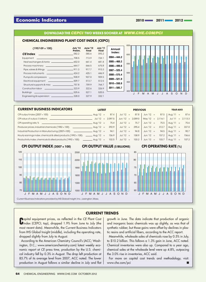
Economic Indicators
CURRENT BUSINESS INDICATORS LATEST PREVIOUS YEAR AGO
CPI output index (2007 = 100) Aug. '12 = 87.4 Jul. '12 = 87.8 Jun. '12 = 87.5 Aug. '11 = 87.6
CPI value of output, $ billions Jul. '12 = 2,097.5 Jun. '12 = 2,059.0 May. '12 = 2,116.1 Jul. '11 = 2,113.3
CPI operating rate, % Aug. '12 = 75.4 Jul. '12 = 75.7 Jun. '12 = 75.5 Aug. '11 = 75.6
Producer prices, industrial chemicals (1982 = 100) Aug. '12 = 292.9 Jul. '12 = 295.4 Jun. '12 = 312.7 Aug. '11 = 337.0
Industrial Production in Manufacturing (2007=100) Aug. '12 = 94.1 Jul. '12 = 94.8 Jun. '12 = 94.5 Aug. '11 = 90.7
Hourly earnings index, chemical & allied products (1992 = 100) Aug. '12 = 156.9 Jul. '12 = 158.9 Jun. '12 = 157.2 Aug. '11 = 156.6
Productivity index, chemicals & allied products (1992 = 100) Aug. '12 = 102.5 Jul. '12 = 103.2 Jun. '12 = 103.7 Aug. '11 = 107.2
60
65
70
75
80
85
1000
1300
1600
1900
2200
2500
J F M A M J J A S O N D J F M A M J J A S O N D J F M A M J J A S O N D
70
80
90
100
110
120
CPI OUTPUT INDEX (2007 = 100) CPI OUTPUT VALUE ($ BILLIONS) CPI OPERATING RATE (%)
400
450
500
550
600
650
J F M A M J J A S O N D
DOWNLOAD THE CEPCI TWO WEEKS SOONER AT WWW.CHE.COM/PCI
CURRENT TRENDS
2010 2011 2012
CHEMICAL ENGINEERING PLANT COST INDEX (CEPCI)
(1957-59 = 100) July '12Prelim.
June '12Final
July '11Final
CE Index 582.2 585.6 593.2
Equipment 708.5 713.9 724.1
Heat exchangers & tanks 652.0 661.4 681.8
Process machinery 664.7 666.5 675.8
Pipe, valves & fittings 911.3 917.7 915.3
Process instruments 424.2 425.1 446.9
Pumps & compressors 928.9 927.0 909.5
Electrical equipment 509.7 513.7 512.5
Structural supports & misc 757.8 759.9 764.7
Construction labor 323.9 322.6 326.9
Buildings 525.6 527.1 520.5
Engineering & supervision 328.0 327.9 332.1
Current Business Indicators provided by IHS Global Insight, Inc., Lexington, Mass.
Capital equipment prices, as reflected in the CE Plant Cost Index (CEPCI; top), dropped 1.9% from June to July (the
most recent data). Meanwhile, the Current Business Indicators from IHS Global Insight (middle), including the operating rate, dropped slightly from July to August.
According to the American Chemistry Council’s (ACC; Wash-ington, D.C.; www.americanchemistry.com) latest weekly eco-nomic report at CE press time, production by the U.S. chemi-cal industry fell by 0.3% in August. The drop left production at 85.7% of its average level from 2007, ACC noted. The lower production in August follows a similar decline in July and flat
growth in June. The data indicate that production of organic and inorganic basic chemicals was up slightly, as was that of synthetic rubber, but those gains were offset by declines in plas-tic resins and artificial fibers, according to the ACC report.
Meanwhile, wholesale sales of chemicals rose by 0.5% in July, to $10.2 billion. This follows a 1.3% gain in June, ACC noted. Chemical inventories were also up. Compared to a year ago, chemical sales at the wholesale level were up 4.8%, outpacing the 3.0% rise in inventories, ACC said.
For more on capital cost trends and methodology, visit:www.che.com/pci ■
Annual
Index:
2004 = 444.2
2005 = 468.2
2006 = 499.6
2007 = 525.4
2008 = 575.4
2009 = 521.9
2010 = 550.8
2011 = 585.7
64 CHEMICAL ENGINEERING WWW.CHE.COM OCTOBER 2012

ChemInnovations and Chemical Engineering Magazine are excited to present eLearning On Demand. This new feature allows you the convenience of watching online courses anytime, anywhere, and at your own pace. 2 hour courses start at $49. Receiving educational training has never been easier!
Visit www.cpievent.com/elearning and use promo code TRIAL to view a free trial of ChemInnovations’ 2011 Keynote Presentation “U.S. Oil, Natural Gas, and Natural Gas Liquids (NGL) Outlook and its Impact on the Chemical Industry by 2020.”
Learn valuable information relevant to your daily work
without having to leave your desk!
Visit the BRAND NEW eLearning On Demand site and enjoy the luxury of receiving training without leaving the office!
www.cpievent.com/elearning
OUR INDUSTRY EXPERTS COVER DOZENS OF TOPICS INCLUDING:
» Global Energy Outlook » Regulatory Issues » Process, Design and Operations » EH & S » Equipment Maintenance » Equipment Reliability » Instrumentation » Controls » Automation » And more…

Swagelok® Pressure Regulators are now an even better choice for all
your pressure regulator needs. Why? Well, alongside our proven experience
and expertise, our range now covers sizes from 1/8 to 4 in. and all your
regulator needs – high-fl ow capability, two-stage, back-pressure and
vaporizing models. With our regulators you get accuracy, sensitivity and
pressure stability. In short – total predictability. Exactly what you would expect.
Visit swagelok.com/pressure.
Make the unpredictable totally predictable.
© 2
012 S
wag
elo
k C
om
pany
Circle 21 on p. 60 or go to adlinks.che.com/40272-21