chbe320 lecture iii actuator and control valve selection · actuator and control valve selection...
TRANSCRIPT

3-1CHBE320 Process Dynamics and Control Korea University
CHBE320 LECTURE IIIACTUATOR AND CONTROL VALVE
SELECTION
Professor Dae Ryook Yang
Spring 2018Dept. of Chemical and Biological Engineering
Korea University

3-2CHBE320 Process Dynamics and Control Korea University
Road Map of the Lecture III
• Visit Actuator
– What is actuator?– D/A converter, Kinds of Valves– Valve characteristics– Selection of control valves
PROCESS
Sensor
Actuator Controller +-

3-3CHBE320 Process Dynamics and Control Korea University
INTRODUCTION TO ACTUATOR
• What is actuator?– Actuator converts the command signal from controllers
or higher-level components into physical adjustment in adjustable process variable
• Actuator types– Control valve: pneumatic, electric, hydraulic– Electric heater output: SCR, thyristor– Pump/Motor speed: inverter– Displacement: pneumatic, electric, hydraulic
ActuatorAdjustment of Physical Variable
(F, motor speed, …)
Command signal
(V, mA, psig, …)
3-4CHBE320 Process Dynamics and Control Korea University
ACTUATOR AND D/A CONVERTER
• Actuator– Convert the industrial standard signal to action such as valve
opening, power level, displacement, and etc.– Standard instrumentation signal levels and signal conversion
transmitters are used.– Actuator power
• Pneumatic: simple, low cost, fast, low torque, hysteresis• Electric: motor and gear box, high torque, slow• Hydraulic: high torque, fast, expensive
• Digital-to-Analog (D/A) converter (+Hold)– Digital signal is converted to continuous signal and the signal is
hold until the signal is changed– Specification: hold type, resolution (8bit, 12bit, 16bit)
3-5CHBE320 Process Dynamics and Control Korea University
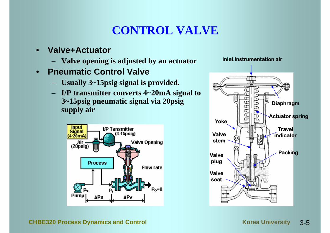
CONTROL VALVE• Valve+Actuator
– Valve opening is adjusted by an actuator• Pneumatic Control Valve
– Usually 3~15psig signal is provided.– I/P transmitter converts 4~20mA signal to
3~15psig pneumatic signal via 20psig supply air
Inlet instrumentation air
Diaphragm
Actuator springYoke
Valvestem
Travelindicator
Valveplug
Valveseat
Packing

3-6CHBE320 Process Dynamics and Control Korea University
CONTROL VALVE IMPLEMENTATION
• For the maintenance– Bypass– Block valves
• Installation– Horizontal– Vertical– Flange type– Screw type– Reducer may be
required

3-7CHBE320 Process Dynamics and Control Korea University
AIR-TO-OPEN OR AIR-TO-CLOSE
• As air pressure increases, the valve opening can becomes larger or smaller
• Air-to-open (normally closed, fail close): as the air P increases, the valve opening gets larger
• Air-to-close (normally open, fail open): as the air P increases, the valve opening gets smaller
• The selection should be made based on the safety consideration– Furnace fuel valve should be closed in case of utility failure– Coolant valve in exothermic reactor should be open in case of utility failure

3-8CHBE320 Process Dynamics and Control Korea University
CONTROL VALVE PACKING
• Packing is essential to maintain the sealing• Packing has to be replaced periodically• Excessive usage may shorten the lifetime of the
packing• Control action should not be too vigorous in
order to prevent the excessive wear

3-9CHBE320 Process Dynamics and Control Korea University
CONTROL VALVE CLASSIFICATION
Control Valve
Linear motion
Rotary motion
GlobeDiaphragmPinch or clampGate
2 wayangle
3 wayDouble seated
Single seated
Split bodied
Eccentric plugButterflyBall
Butterfly Diaphragm Pinch Gate

3-10CHBE320 Process Dynamics and Control Korea University
VALVE TYPES
• Globe valve– rugged, usually the most expensive, particularly in the larger sizes,
accurate and repeatable control, high pressure drop• Gate Valve
– sliding disc (gate), ideal for high pressure and high temperature applications where operation is infrequent, multi-turn or long stroke pneumatic and electro-hydraulic actuators are needed, poor control
• Ball Valve– tight shutoff, high capacity with just a quarter-turn to operate
• Butterfly Valve– damper valve , most economical valves, high torque required
• Diaphragm Valve– simplest, tight shutoff, isolated, ideal for corrosive, slurry and
sanitary services.

3-11CHBE320 Process Dynamics and Control Korea University
VALVE EQUATION
• Basic Equation
where is the valve stem position.– Valve coeff. (Cv) is decided by valve size– Valve trim type for different plug
• Linear:• Square-Root (Quick Opening):• Equal Percentage:
• R: rangeability (ratio between minimum flow and maximum flow) the bigger R is, the more accurate
10)()(
s
vv g
PfCq
)(f )(f
1)( Rf

3-12CHBE320 Process Dynamics and Control Korea University
VALVE TRIM(PLUG) TYPE
• Equal Percentage– Most commonly used– Used where large
pressure drop is expected• Linear
– Used where fairly constant press. drop is expected
– Used for liquid level or flow loop
• Quick Opening– Used for frequently on-off
service– Used where instantly
large flow is needed

3-13CHBE320 Process Dynamics and Control Korea University
VALVE FLOW CHARACTERISTICS
• Inherent characteristics– All P is in valve: no P in process
• Installed characteristics– Total P in a system is provided by a pump or compressor– Change in valve opening flow change in process change
in P across the valve– Linear plug does not lead to linear
behavior when installed
svtotal PPP 2kqPs
2max
2
max kqgCqP s
vtotal

3-14CHBE320 Process Dynamics and Control Korea University
NONLINEAR BEHAVIOR
• Flow vs. valve trim (installed)
where
implicit nonlinear equation of flow and valve trim
• The pumping requirement (Ptotal) is determined by the P in both process and control valve at the max. flow
10)()(
s
vv g
PfCq
22max
2
max kqkqgCqPPP s
vstotalv

3-15CHBE320 Process Dynamics and Control Korea University
VALVE SIZING• Step1
– Decide max. and min. flow of a fluid (rangeability for equal percentage valve) and Ptotal .
• Step2– Define a max. allowable Pv when the valve is wide open.– It should be 10~15% of Ptotal or about 10psi whichever is greater.
• Step3– Calculate the installed valve characteristic.– It should be linear around the region you want.
• Step4– Adjust the pumping requirement (Ptotal) if possible and valve coeff.
(Cv) so that the max. flow can be achieved at about 80-85% opening and the min. flow can be achieved at about 10-15% opening .
– Make sure that the Pv when the valve is wide open is not over the limit in Step2.
– Select valve size with suitable Cv value. The valve size should not be smaller than half of pipe size.

3-16CHBE320 Process Dynamics and Control Korea University
OTHER CONSIDERTIONS• If pump characteristic curve is available
– For many pumps, as flow increases, the pump discharge pressure is decreased.
– Then the pump discharge P (Ptotal) will change with flow rate.• Choked flow (flow at sound velocity)
– When the P across the valve is large, sonic velocity is attained. A different type of flow equation should be used.
– When P gets larger, then choked flow occurs, and the downstream pressure does not influence the flow rate.
– Also, if the P is too high, flashing may occur for liquid flows. (Noisy)– Thus, avoid excessive pressure drop.
• If lager valve is used, there will be less Pv and lesspumping requirement (Ptotal) is needed. However, thecontrollability of the flow is sacrificed. (trade-off)
• As a rule of thumb, the Pv should be around 1/3~1/4 ofPtotal at nominal flow rate.

3-17CHBE320 Process Dynamics and Control Korea University
HYSTERESIS AND VALVE POSITIONER
• Hysteresis– Due to friction between the stem and packing, loose linkage,
pressure drop, stiction or etc.– When the command signal (pneumatic signal) is going up and
down, the flow rate will not be same even though the command signal is same depending on the direction of signal change.
– Remedy• Change the command signal with the same direction by lowering
or increasing it momentarily• Use valve positioner
• Valve positioner– The valve positioner is a controller which can synchronize the
command signal and its corresponding valve stem position.– By use of valve positioner, hysteresis can be overcome.
3-18CHBE320 Process Dynamics and Control Korea University
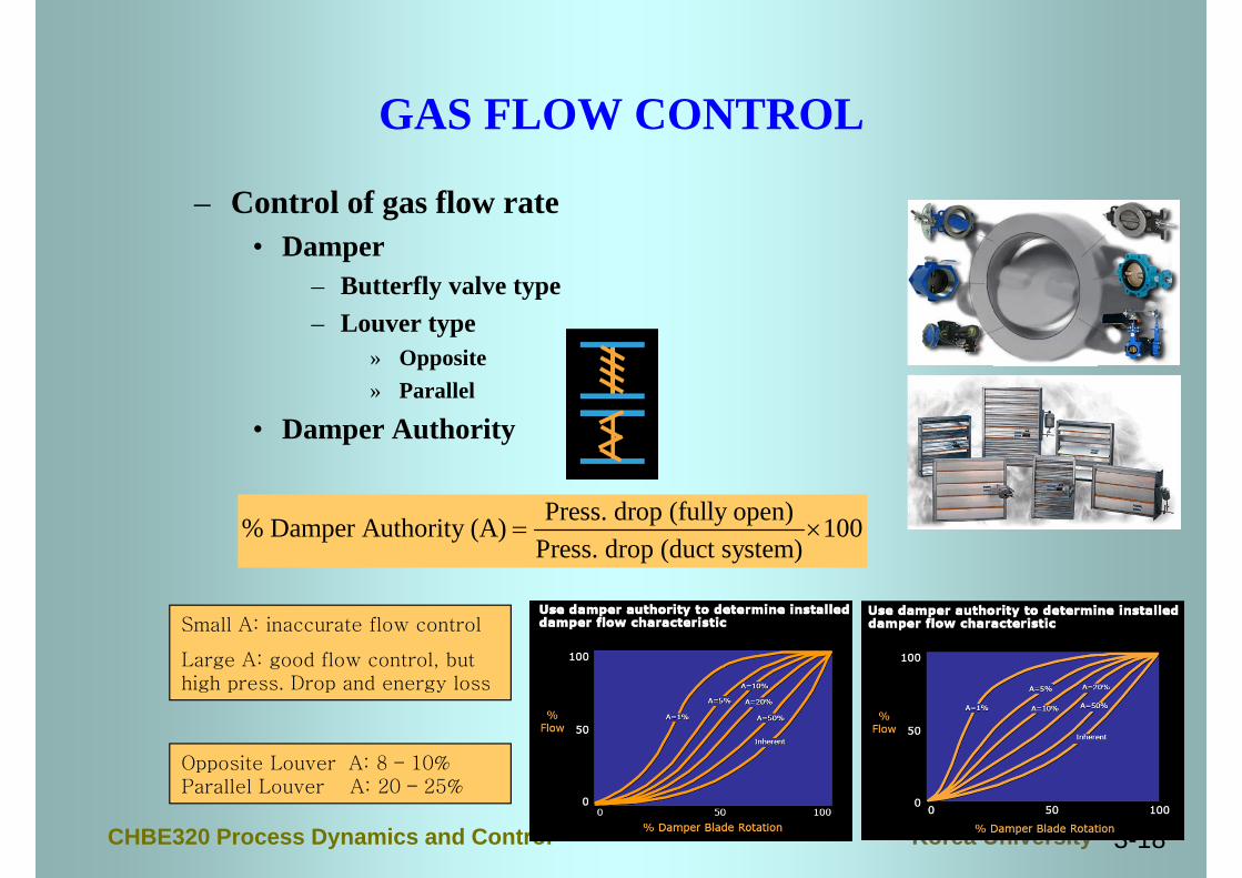
GAS FLOW CONTROL
– Control of gas flow rate• Damper
– Butterfly valve type– Louver type
» Opposite» Parallel
• Damper Authority
Press. drop (fully open)% Damper Authority (A) 100Press. drop (duct system)
Small A: inaccurate flow control
Large A: good flow control, but high press. Drop and energy loss
Opposite Louver A: 8 – 10%Parallel Louver A: 20 – 25%
3-19CHBE320 Process Dynamics and Control Korea University
MOTOR SPEED CONTROL
• Control of motor– Need to control rpm, position, acceleration, torque, etc.
• DC Motor– The rpm changes continuously depending on the voltage imposed.– High price and larger size for power than AC motor– Need a converter from AC to DC
• AC Motor– Low price and low maintenance cost– Small size for power and reliable– Hard to control the motor speed accurately and lower performance at
low speed than DC motor– Widely used for the cases where accurate speed control is not
required such as fan, pump, compressor and etc.– Recent development of electronics and control technique, the control
performance is approaching to that of DC motor and the usage of AC motor will be extended.
– To control the speed of AC motor, the inverter is widely used.
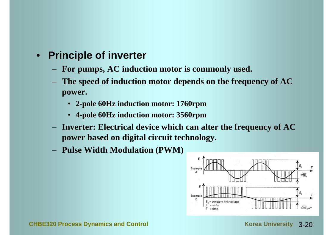
3-20CHBE320 Process Dynamics and Control Korea University
• Principle of inverter– For pumps, AC induction motor is commonly used.– The speed of induction motor depends on the frequency of AC
power.• 2-pole 60Hz induction motor: 1760rpm• 4-pole 60Hz induction motor: 3560rpm
– Inverter: Electrical device which can alter the frequency of AC power based on digital circuit technology.
– Pulse Width Modulation (PWM)

3-21CHBE320 Process Dynamics and Control Korea University
• Traditional flow control by blower – At constant speed of fan motor, adjust the opening of damper
or louver to control the flow rate• Fan motor is designed commonly oversized by 10-15%• The sizing of damper/louver for operating condition is important
to control the flow rate precisely.• Through the pressure loss, the flow rate is controlled. (35-50%
energy loss)
• Blower flow control using Inverter– The speed of fan motor is adjusted freely using inverter
• Pressure loss is maintained almost constant• Less energy is required at low flow rate (low motor speed): 50-
60% energy saving compared to pressure loss• Instead of damper/louver, inverters need to be installed• Requires shut-off valve if seal is needed at zero flow rate

3-22CHBE320 Process Dynamics and Control Korea University
• Example of energy saving– 2400 gpm@3560rpm– Pump: 550hp, 77.5% efficiency– Flow rates: 2400(A)1200(B)gpm
– For constant speed pump• using control valve (friction loss)• 400hp, 62% efficiency
– For variable speed pump• 70hp, 78% efficiency
– Comparisons• Variable speed pump is more energy efficient• Pump sized can be reduced by 330hp• Almost no loss in pump efficiency

3-23CHBE320 Process Dynamics and Control Korea University
• Calculation of energy saving– 200hp constant speed pump: at normal operating flow
condition, 185hp (efficiency=0.92)• Cost of electricity: $0.035/Kwh• Operation pattern: 100% load (15%), 87.5% load (65%), 50%
load (15%) total 95% turned-on• Annual operating time: 8760 hr • Annual cost: 0.742(Kw/hp)*185hp/0.92*$0.035*8760*0.95=$43,693
– Variable speed pump• F=(frictional head)/(total head) and assume F=75/(75+25)=0.75.• Pressure drop ratio for valve: 75%F • Saving: (0.15*16%)+(0.65*31%)+(0.15*69%)=32.9%• Money saving: $43,693*0.329=$14,375
– Other advantages• Low noise• Long life of pump by soft startup
<Energy savings chart of variable speed pump>