charles steinmetz theorycalculatio00steiiala
TRANSCRIPT

8/2/2019 Charles Steinmetz Theorycalculatio00steiiala
http://slidepdf.com/reader/full/charles-steinmetz-theorycalculatio00steiiala 1/557
8/2/2019 Charles Steinmetz Theorycalculatio00steiiala
http://slidepdf.com/reader/full/charles-steinmetz-theorycalculatio00steiiala 2/557

8/2/2019 Charles Steinmetz Theorycalculatio00steiiala
http://slidepdf.com/reader/full/charles-steinmetz-theorycalculatio00steiiala 3/557
QC
6*/l
,5?

8/2/2019 Charles Steinmetz Theorycalculatio00steiiala
http://slidepdf.com/reader/full/charles-steinmetz-theorycalculatio00steiiala 4/557

8/2/2019 Charles Steinmetz Theorycalculatio00steiiala
http://slidepdf.com/reader/full/charles-steinmetz-theorycalculatio00steiiala 5/557

8/2/2019 Charles Steinmetz Theorycalculatio00steiiala
http://slidepdf.com/reader/full/charles-steinmetz-theorycalculatio00steiiala 6/557

8/2/2019 Charles Steinmetz Theorycalculatio00steiiala
http://slidepdf.com/reader/full/charles-steinmetz-theorycalculatio00steiiala 7/557
THEORY AND CALCULATION
ALTERNATING CURRENT
PHENOMENA/
BY
CHARLES PROTEUS.STEINMETZ
WITH THE ASSISTANCE OF
ERNST J. BERG
THIRD EDITION, REVISED AND ENLARGED
NEW YORK
ELECTRICAL WORLD AND ENGINEERINCORPORATED
I9OO

8/2/2019 Charles Steinmetz Theorycalculatio00steiiala
http://slidepdf.com/reader/full/charles-steinmetz-theorycalculatio00steiiala 8/557
COPYRIGHT, 1900,
ELECTRICAL WORLD AND ENGINEER.
(INCORPORATED.)
TYPOGRAPHY BY C. J. PETERS * SON, BOSTON.

8/2/2019 Charles Steinmetz Theorycalculatio00steiiala
http://slidepdf.com/reader/full/charles-steinmetz-theorycalculatio00steiiala 9/557
1C 27
DEDICATEDTO THE
MEMORY OF MY FATHER,
CARL HEINRICH STEINMETZ.

8/2/2019 Charles Steinmetz Theorycalculatio00steiiala
http://slidepdf.com/reader/full/charles-steinmetz-theorycalculatio00steiiala 10/557
8/2/2019 Charles Steinmetz Theorycalculatio00steiiala
http://slidepdf.com/reader/full/charles-steinmetz-theorycalculatio00steiiala 11/557
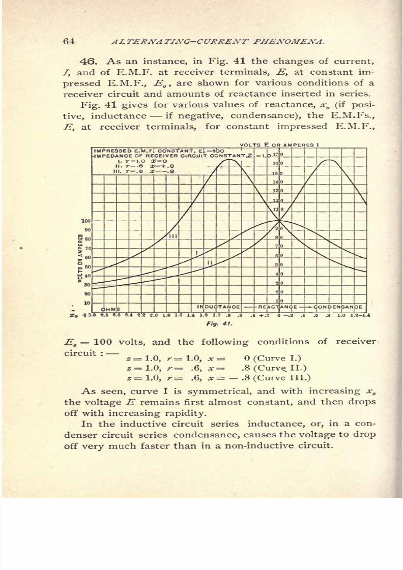
PREFACE TO THE THIRD EDITION.
IN preparing the third edition, great improvements have
been made, and a considerable part of the work entirely re-
written, with the addition of much new material. A number
of new chapters have been added, as those on vector rep-
resentation of double frequency quantities as power and
torque, and on symbolic representation of general alternating
waves. Many chapters have been more or less completely
rewritten and enlarged, as those on the topographical
method, on distributed capacity and inductance, on fre-
quencyconverters and induction
machines, etc.,and the
size of the -volume thereby greatly increased.
The denotations have been carried through systematically,
by distinguishing between complex vectors and absolute
values throughout the text;and the typographical errors
which had passed into the first and second editions, have
been eliminated with the utmost care.
To those gentlemen who so materially assisted me by
drawing my attention to errors in the previous editions, I
herewith extend my best thanks, and shall be obliged for
any further assistance in this direction. Great credit is
due to the publishers, who have gone to very considerable
expense in bringing out the third edition in its present form,
and carrying out all my requests regarding changes and
additions. Many thanks are due to Mr. Townsend Wolcott
for his valuable and able assistance in preparing and editing
the third edition.
CHARLES PROTEUS STEINMETZ.
CAMP MOHAWK, VIELE'S CREEK,
July, jgoo.
8/2/2019 Charles Steinmetz Theorycalculatio00steiiala
http://slidepdf.com/reader/full/charles-steinmetz-theorycalculatio00steiiala 12/557

8/2/2019 Charles Steinmetz Theorycalculatio00steiiala
http://slidepdf.com/reader/full/charles-steinmetz-theorycalculatio00steiiala 13/557
PREFACE TO FIRST EDITION.
THE following volume is intended as an exposition of
the methods which I have found useful in the theoretical
investigation and calculation of the manifold phenomena
taking place in alternating-current circuits, and of their
application to alternating-current apparatus.
While the book is not intended as first instruction for
a beginner, but presupposes some knowledge of electrical
engineering, I have endeavored to make it as elementary
as possible, and have therefore only used common algebra
and trigonometry, practically excluding calculus, except in
106 to 115 and Appendix II.;and even 106 to 115
have been paralleled by the elementary approximation of
the same phenomenon in 102 to 105.
All the methods used in the book have been introduced
and explicitly discussed, with instances of their application,
the first part of the book being devoted to this. In the in-
vestigation of alternating-current phenomena and apparatus,
one method only has usually been employed, though the
other available methods are sufficiently explained to show
their application.
A considerable part of the book is necessarily devoted
to the application of complex imaginary quantities, as the
method which I found most useful in dealing with alternat-
ing-current phenomena ;and in this regard the book may be
considered as an expansion and extension of my paper on
the application of complex imaginary quantities to electri-
calengineering, read before the International
Electrical Con-

8/2/2019 Charles Steinmetz Theorycalculatio00steiiala
http://slidepdf.com/reader/full/charles-steinmetz-theorycalculatio00steiiala 14/557

8/2/2019 Charles Steinmetz Theorycalculatio00steiiala
http://slidepdf.com/reader/full/charles-steinmetz-theorycalculatio00steiiala 15/557
8/2/2019 Charles Steinmetz Theorycalculatio00steiiala
http://slidepdf.com/reader/full/charles-steinmetz-theorycalculatio00steiiala 16/557

8/2/2019 Charles Steinmetz Theorycalculatio00steiiala
http://slidepdf.com/reader/full/charles-steinmetz-theorycalculatio00steiiala 17/557
CONTENTS.
CHAP. I. Introduction.
1, p. 1. Fundamental laws of continuous current circuits.
2, p. 2. Impedance, reactance, effective resistance.
3, p. 3. Electro-magnetism as source of reactance.
4, p. 5. Capacity as source of reactance.
5, p. 6. Joule's law and power equation of alternating circuit.
6, p. 6. Fundamental wave and higher harmonics, alternating
waves with and without even harmonics.
7, p. 9. Alternating waves as sine waves.
CHAP. II. Instantaneous Values and Integral Values.
8, p. 11. Integral values of wave.
9, p. 13. Ratio of mean to maximum to effective value of wave.
CHAP. III. Law of Electro-magnetic Induction.
11, p. 16. Induced E.M.F. mean value.
12, p. 17. Induced E.M.F. effective value.
13, p. 18. Inductance and reactance.
CHAP. IV. Graphic Representation.
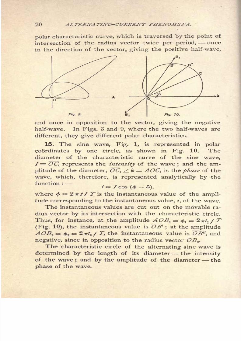
14, p. 19. Polar characteristic of alternating wave.
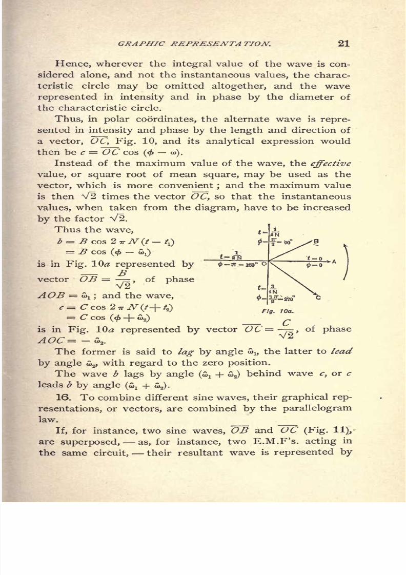
15, p. 20. Polar characteristic of sine wave.
16, p. 21. Parallelogram of sine waves, Kirchhoff's laws, and energy
equation.
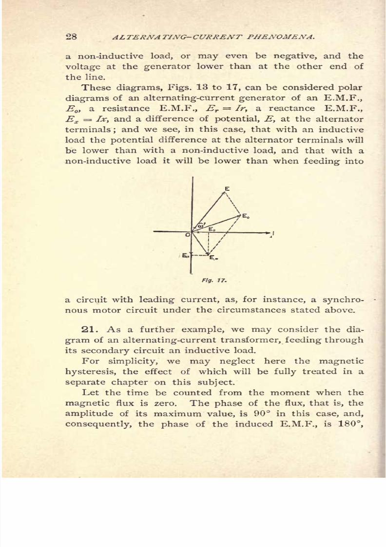
17, p. 23. Non-inductive circuit fed over inductive line, instance.
18, p. 24. Counter E.M.F. and component of impressed E.M.F.
19, p. 26. Continued.
20, p 26. Inductive circuit and circuit with leading current fed over
inductive line. Alternating-current generator.
21, p. 28. Polar diagram of alternating-current transformer, instance.
22, p. 30. Continued.
CHAP. V. Symbolic Method.
23, p. 33. Disadvantage of graphic method for numerical calculatioa
24, p. 34. Trigonometric calculation.
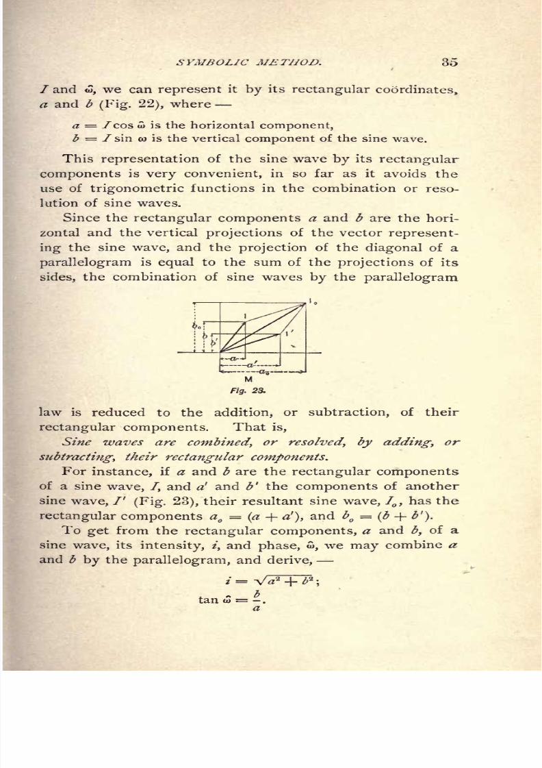
25, p. 34. Rectangular components of vectors.
26, p. 36. Introduction of / as distinguishing index.
27, 36. Rotation of vector 180 and 90. =

8/2/2019 Charles Steinmetz Theorycalculatio00steiiala
http://slidepdf.com/reader/full/charles-steinmetz-theorycalculatio00steiiala 18/557

8/2/2019 Charles Steinmetz Theorycalculatio00steiiala
http://slidepdf.com/reader/full/charles-steinmetz-theorycalculatio00steiiala 19/557
CONTENTS. xiii
CHAP. IX. Resistance and Reactance of Transmission Lines. Continued.
59, p. 86. Instance.
60, p. 87. Maximum power supplied over inductive line.
61, p. 88. Dependence of output upon the susceptance of the re-
ceiver circuit.
62, p. 89. Dependence of output upon the conductance of the re-
ceiver circuit.
63, p. 90. Summary.
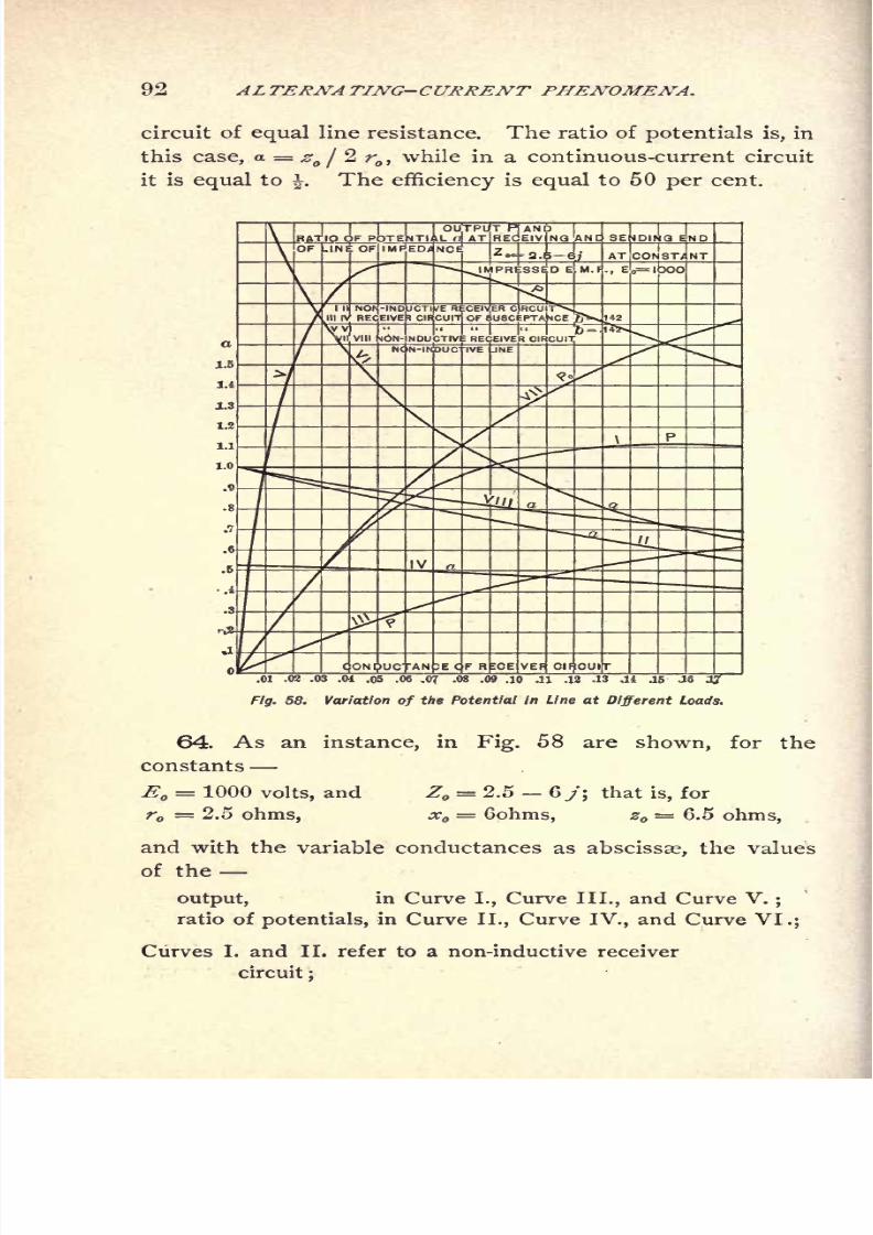
64, p. 92. Instance.
65, p. 93. Condition of maximum efficiency.
6, p. 96. Control of receiver voltage by shunted susceptance.
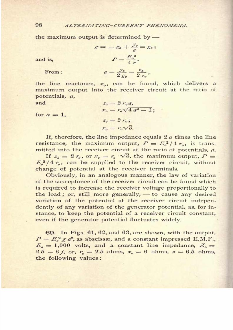
67, p. 97. Compensation for line drop by shunted susceptance.
68, p. 97. Maximum output and discussion.
69, p. 98. Instances.
70, p. 101. Maxium rise of potential in receiver circuit.
71, p. 102. Summary and instances.
CHAP. X. Effective Resistance and Reactance.
72, p. 104. Effective resistance, reactance, conductance, and suscep-
tance.
73, p. 105. Sources of energy losses in alternating-current circuits.
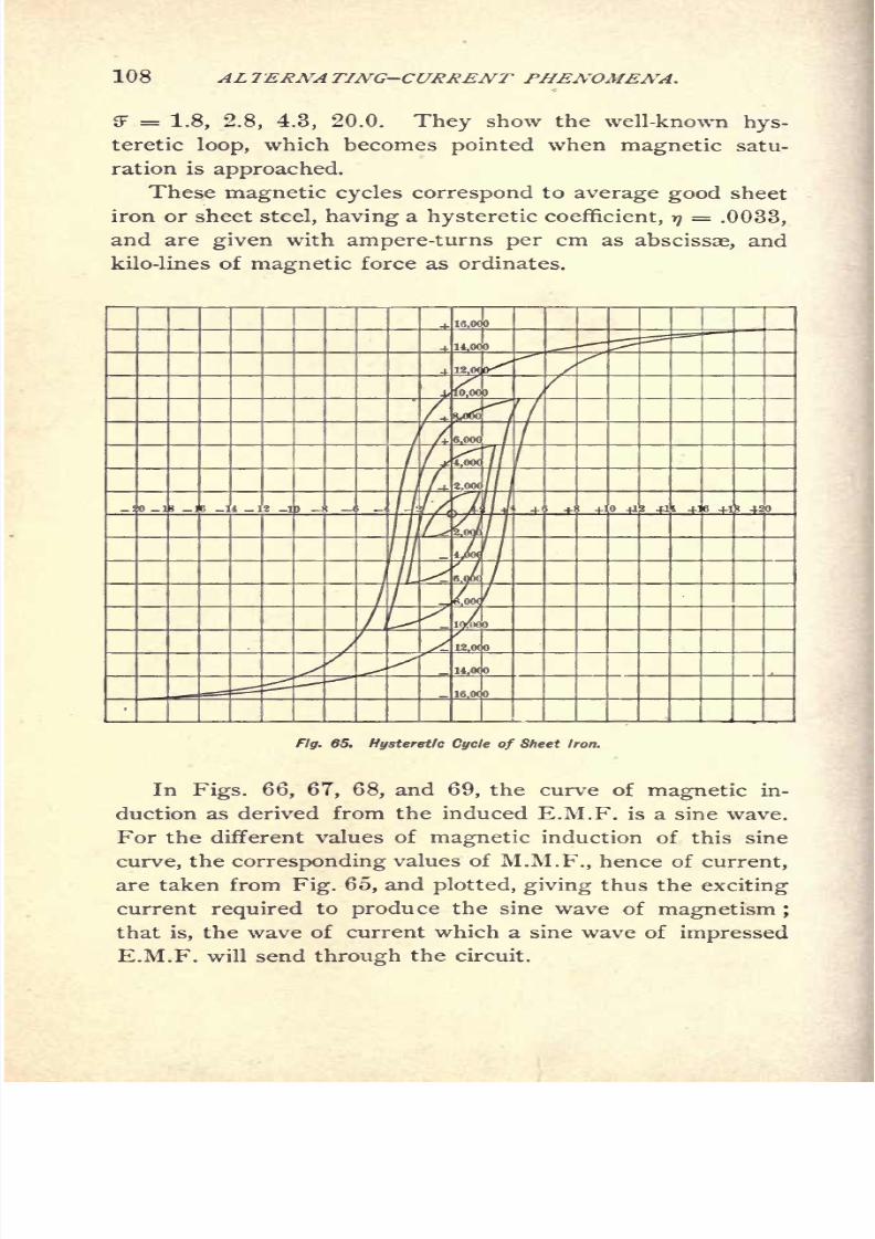
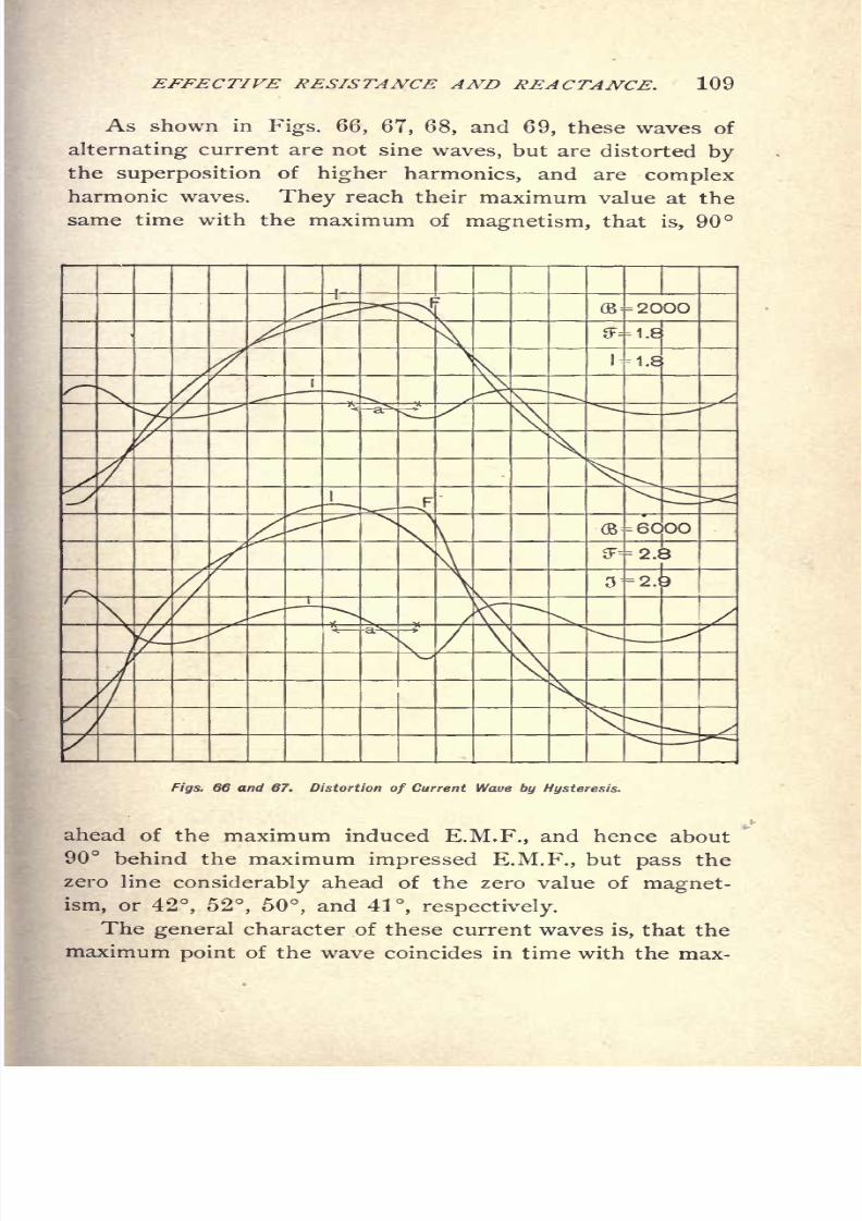
74, p. 106. Magnetic hysteresis.
75, p. 107. Hysteretic cycles and corresponding current waves.
76, p.111. Action of air-gap and of induced current on hysteretic
distortion.
77, p.111. Equivalent sine wave and wattless higher harmonic.
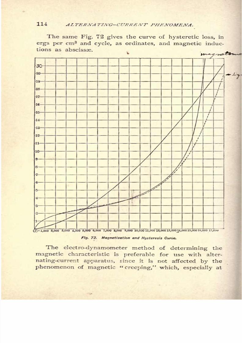
78, p. 113. True and apparent magnetic characteristic.
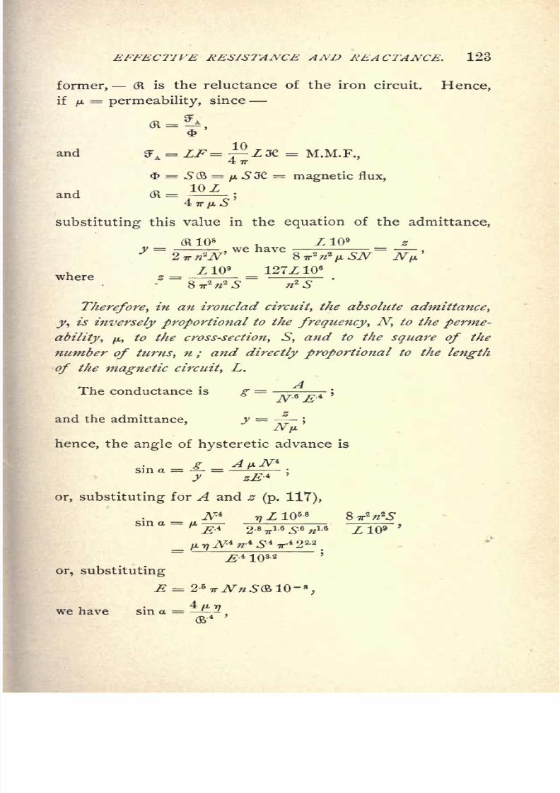
79, p. 115. Angle of hysteretic advance of phase.
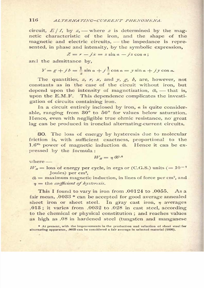
80, p. 116. Loss of energy by molecular magnetic friction.
81, p. 119. Effective conductance, due to magnetic hysteresis.
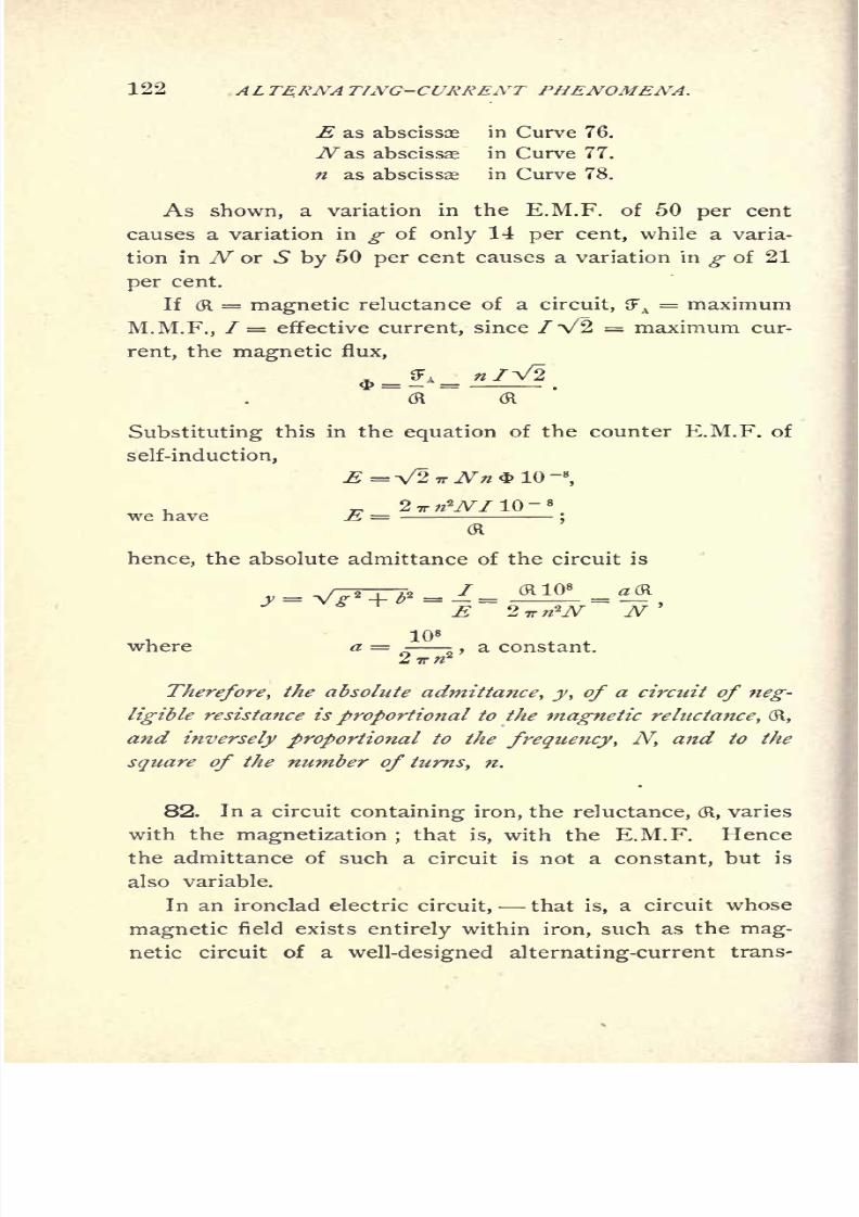
82, p. 122. Absolute admittance of ironclad circuits and angle of
hysteretic advance.
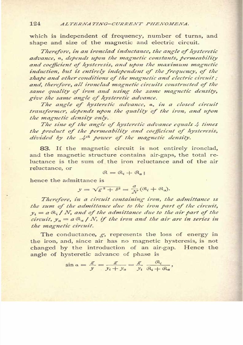
83, p. 124. Magnetic circuit containing air-gap.
84, p. 125. Electric constants of circuit containing iron.
85, p. 127. Conclusion.
CHAP. XI. Foucault or Eddy Currents.
86, p. 129. Effective conductance of eddy currents.
87, p. 130. Advance angle of eddy currents.
88, p. 131. Loss of power by eddy currents, and coefficient of eddy
currents.
89, p. 131. Laminated iron.
90, p. 133. Iron wire.
91, p. 135. Comparison of sheet iron and iron wire.
92, p. 136. Demagnetizing or screening effect of eddy currents.
93, p. 138. Continued.
94, p. 138. Large eddy currents.
8/2/2019 Charles Steinmetz Theorycalculatio00steiiala
http://slidepdf.com/reader/full/charles-steinmetz-theorycalculatio00steiiala 20/557
CONTENTS.
CHAP. XI. Foucault or Eddy Currents. Continued.
95, p. 139. Eddy currents in conductor and unequal current dis-
tribution.
96, p. 140. Continued.
97, p. 142. Mutual inductance.
98, p. 144. Dielectric and electrostatic phenomena.
99, p. 145. Dielectric hysteretic admittance, impedance, lag, etc.
100, p. 147. Electrostatic induction or influence.
101, p. 149. Energy components and wattless components.
CHAP. XII. Power, and Double Frequency Quantities in General.
102, p. 150. Double frequency of power.
103, p. 151. Symbolic representation of power.
104, p. 153. Extra-algebraic features thereof.
105, p. 155. Combination of powers.
106, p. 156. Torque as double frequency product.
CHAP. XIII. Distributed Capacity, Inductance, Resistance, and Leak-
age.
107, p. 158. Introduction.
108, p. 159. Magnitude of charging current of transmission lines.
109, p. 160. Line capacity represented by one condenser shunted
across middle of line.
110, p. 161. Line capacity represented by three condensers.
111, p. 163. Complete investigation of distributed capacity, induc-
tance, leakage, and resistance.
112, p. 165. Continued.
113,p.
166. Continued.
114, p. 166. Continued.
115, p. 167. Continued.
116, p. 169. Continued.
117, p. 170. Continued.
118, p. 170. Difference of phase at any point of line.
119, p. 17-2. Instance.
120, p. 173. Further instance and discussion.
121, p. 178. Particular cases, open circuit at end of line, line
grounded at end, infinitely ong conductor, generator feeding
into closed circuit.
122, p. 181. Natural period of transmission line.
123, p. 186. Discussion.
124, p. 190. Continued.
125, p. 191. Inductance of uniformly charged line.
CHAP. XIV. The Alternating-Current Transformer.
126, p. 193. General.
127, p. 193. Mutual inductance and self-inductance of transformer.
194. circuit of transformer.
8/2/2019 Charles Steinmetz Theorycalculatio00steiiala
http://slidepdf.com/reader/full/charles-steinmetz-theorycalculatio00steiiala 21/557

8/2/2019 Charles Steinmetz Theorycalculatio00steiiala
http://slidepdf.com/reader/full/charles-steinmetz-theorycalculatio00steiiala 22/557
xvi CONTENTS.
CHAP. XVI. Induction Machines Continued.
168, p.
265. Inductiongenerator.
169, p. 268. Power factor of induction generator.
170, p. 269. Constant speed, induction generator.
171, p. 272. Induction generator and synchronous motor.
172, p. 274. Concatenation or tandem control of induction motors.
173, p.276. Calculation of concatenated couple.
174, p.280. Numerical instance.
175, p. 281. Single-phase induction motor.
176, p. 283. Starting devices of single-phase motor.
177, p. 284. Polyphase motor on single-phase circuit.
178, p. 286. Condenser intertiary circuit.
179, p. 287. Speed curves with condenser.
180, p. 291. Synchronous induction motor.
181, p. 293. Hysteresis motor.
CHAP. XVII. Alternate-Current Generator.
182, p. 297. Magnetic reaction of lag and lead.
183, p. 300. Self-inductance and synchronous reactance.
184, p. 302. Equations of alternator.
185, p. 303. Numerical instance, field characteristic.
186, p. 307. Dependence of terminal voltage on phase relation.
187, p. 307. Constant potential regulation.
188, p. 309. Constant current regulation, maximum output.
CHAP. XVIII. Synchronizing Alternators.
189, p. 311. Introduction.
190, p. 311. Rigid mechanical connection.
191, p. 311. Uniformity of speed
192, p. 312. Synchronizing.
193, p. 313. Running in synchronism.
194, p. 313. Series operation of alternators.
195, p. 314. Equations of synchronous running alternators, synchro-
nizing power.
196, p.317. Special case of equal alternators at equal excitation.
197, p.320. Numerical instance.
CHAP. XIX. Synchronous Motor.
198, p. 321. Graphic method.
199, p. 323. Continued.
200, p. 325. Instance.
201, p. 326. Constant impressed E.M.F. and constant current.
202, p. 329. Constant impressed and counter E.M.F.
203, p. 332. Constant impressed E.M.F. and maximum efficiency.
204, p. 334. Constant impressed E.M.F. and constant output.
205, p. 338. Analytical method. Fundamental equations and power,
characteristic.
8/2/2019 Charles Steinmetz Theorycalculatio00steiiala
http://slidepdf.com/reader/full/charles-steinmetz-theorycalculatio00steiiala 23/557
CONTENTS. xvii
CHAP. XIX. Synchronous Motor Continued.
206, p.
342. Maximumoutput.
207, p. 343. No load.
208, p. 345. Minimum current.
209, p. 347. Maximum displacement of phase.
210, p. 349. Constant counter E.M.F.
211, p. 349. Numerical instance.
212, p. 351. Discussion of results.
CHAP. XX. Commutator Motors.
213, p. 354. Types of commutator motors.
214, p. 354. Repulsion motor as induction motor.
215, p. 356. Two types of repulsion motors.
216, p. 358. Definition of repulsion motor.
217, p. 359. Equations of repulsion motor.
218, p. 360. Continued.
219, p. 361. Power of repulsion motor. Instance.
220, p. 363. Series motor, shunt motor.
221, p. 366. Equations of series motor.222, p. 367. Numerical instance.
223, p. 368. Shunt motor.
224, p. 370. Power factor of series motor.
CHAP. XXI. Reaction Machines.
225, p. 371. General discussion.
226, p. 372. Energy component of reactance.
227, p. 372. Hysteretic energy component of reactance.
228, p. 373. Periodic variation reactance.
229, p. 375. Distortion of wave-shape.
230, p. 377. Unsymmetrical distortion of wave-shape.
231, p. 378. Equations of reaction machines.
232, p. 380. Numerical instance.
CHAP. XXII. Distortion of Wave-shape, and its Causes.
233, p. 383. Equivalent sine wave.
234, p. 383. Cause of distortion.
235, p. 384. Lack of uniformity and pulsation of magnetic field^
S 236, p. 388. Continued.
237, p. 391. Pulsation of reactance.
238, p. 391. Pulsation of reactance in reaction machine.
239, p. 393. General discussion.
240, p. 393. Pulsation of resistance arc.
241, p. 395. Instance.
242, p. 396. Distortion of
wave-shape byarc.
243. p. 397. Discussion.
8/2/2019 Charles Steinmetz Theorycalculatio00steiiala
http://slidepdf.com/reader/full/charles-steinmetz-theorycalculatio00steiiala 24/557

8/2/2019 Charles Steinmetz Theorycalculatio00steiiala
http://slidepdf.com/reader/full/charles-steinmetz-theorycalculatio00steiiala 25/557
CONTENTS. XIX
CHAP. XXVIII. Interlinked Polyphase Systems.
277, p. 452. Interlinked and independent systems.
278, p.452. Star connection and ring connection. Y connection and
delta connection.
279, p.454. Continued.
280, p.455. Star potential and ring potential. Star current and ring
current. Y potential and Y current, delta potential and delta
current.
281, p. 455. Equations of interlinked polyphase systems.
282, p. 457. Continued.
CHAP. XXIX. Transformation of Polyphase Systems.
283, p. 460. Constancy of balance factor.
284, p. 460. Equations of transformation of polyphase systems.
285, p. 462. Three-phase, quarter-phase transformation.
286, p. 463. Some of the more common polyphase transformations.
287, p. 466.f Transformation with change of balance factor.
CHAP. XXX. Copper Efficiency of Systems.
288, p. 468. General discussion.
289, p. 469. Comparison on the basis of equality of minimum dif-
ference of potential.
290, p. 474. Comparison on the basis of equality of maximum dif-
ference of potential.
291, p. 476. Continued.
CHAP. XXXI. Three-phase System.
292, p. 478. General equations.
293, p.
481.Special
cases: balancedsystem,
one branchloaded,
two branches loaded.
CHAP. XXXII. Quarter-phase System.
294, p. 483. General equations.
295, p. 484. Special cases : balanced system, one branch loaded.
APPENDIX I. Algebra of Complex Imaginary Quantities.
296, p. 489. Introduction.
297, p. 489.
Numeration, addition, multiplication,involution.
298, p. 490. Subtraction, negative number.
299, p. 491. Division, fraction.
300, p. 491. Evolution and logarithmation.
301, p. 492. Imaginary unit, complex imaginary number.
302, p. 492. Review.
303, p. 493. Algebraic operations with complex quantities.
304, p. 494. Continued.
305, p. 495. Roots of the unit.
306, p. 495. Rotation.
307, p. 496. Complex imaginary plane.
8/2/2019 Charles Steinmetz Theorycalculatio00steiiala
http://slidepdf.com/reader/full/charles-steinmetz-theorycalculatio00steiiala 26/557
8/2/2019 Charles Steinmetz Theorycalculatio00steiiala
http://slidepdf.com/reader/full/charles-steinmetz-theorycalculatio00steiiala 27/557
THEORY AND CALCULATION
OF
ALTERNATING-CURRENT PHENOMENA.
CHAPTER I.
INTRODUCTION.
1. IN the practical applications of electrical energy, we
meet with two different classes of phenomena, due respec-
tively to the continuous current and to the alternating
current.
The continuous-current phenomena have been brought
within the realm of exact analytical calculation by a few
fundamental laws :
1.) Ohm's law: i = e j r, where r, the resistance, is a
constant of the circuit.
2.) Joule's law: P= izr, where P is the rate at which
energy is expended by the current, i, in the resistance, r.
3.) The power equation : P =ei, where P is the
power expended in the circuit of E.M.F., e, and current, /.
4.) Kirchhoff's laws :
a.} The sum of all the E.M.Fs. in a closed circuit = 0,
if the E.M.F. consumed by the resistance, ir, is also con-
sidered as a counter E.M.F., and all the E.M.Fs. are taken
in their proper direction.
b.) The sum of all the currents flowing towards a dis-
tributing point = 0.
In
alternating-currentcircuits, that is, in circuits con-
veying curr'ents which rapidly and periodically change their
8/2/2019 Charles Steinmetz Theorycalculatio00steiiala
http://slidepdf.com/reader/full/charles-steinmetz-theorycalculatio00steiiala 28/557

8/2/2019 Charles Steinmetz Theorycalculatio00steiiala
http://slidepdf.com/reader/full/charles-steinmetz-theorycalculatio00steiiala 29/557
INTRODUCTION. 3
circuit, but depends upon the frequency, andfrequently,
as in circuits containing iron, or in electrolytic conductors,
upon the E.M.F. also. Hence, while the effective resist-
ance, r, refers to the energy component of E.M.F., or the
E.M.F. in phase with the current, the reactance, x, refers
to the wattless component of E.M.F., or the E.M.F. in
quadrature with the current.
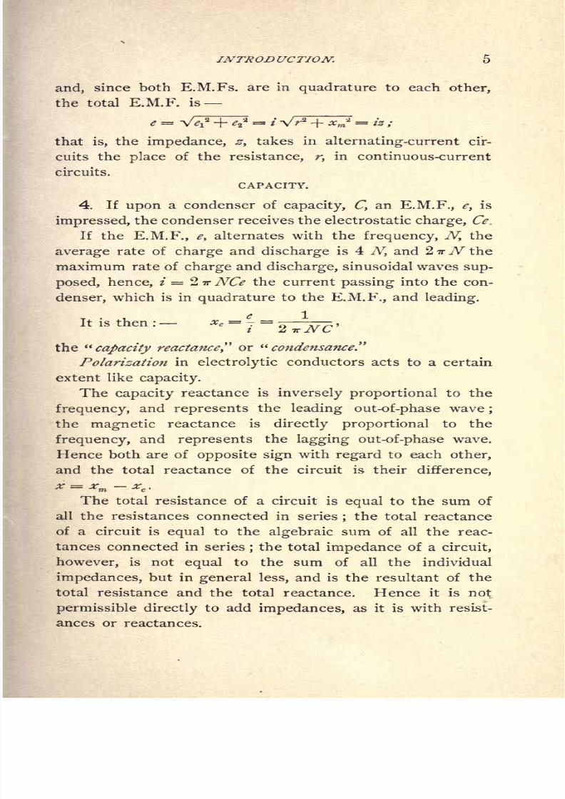
3. The principal sources of reactance are electro-mag-
netism and capacity.
ELECTRO MAGNETISM.
An electric current, i, flowing through a circuit, produces
a magnetic flux surrounding the conductor in lines of
magnetic force (or more correctly, lines of magnetic induc-
tion), of closed, circular, or other form, which alternate
with the alternations of the current, and thereby induce
an E.M.F. in the conductor. Since the magnetic flux is
in phase with the current, and the induced E.M.F. 90, or
a quarter period, behind the flux, this E.M.F. of self-induc-
tance lags 90, or a quarter period, behind the current;that
is, is in quadrature therewith, and therefore wattless.
If now 4> = the magnetic flux produced by, and inter-
linked with, the current i (where those lines of magnetic
force, which are interlinked w-fold, or pass around n turns
of the conductor, are counted n times), the ratio, $ / z, is
denoted by L, and called self-inductance, or the coefficient of
self-induction
of the circuit. It is
numerically equal,
in
absolute units, to the interlinkages of the circuit with the
magnetic flux produced by unit current, and is, in the
system of absolute units, of the dimension of length. In-
stead of the self-inductance, L, sometimes its ratio with
the ohmic resistance, r, is used, and is called the Time-
Constant of the circuit :

8/2/2019 Charles Steinmetz Theorycalculatio00steiiala
http://slidepdf.com/reader/full/charles-steinmetz-theorycalculatio00steiiala 30/557
8/2/2019 Charles Steinmetz Theorycalculatio00steiiala
http://slidepdf.com/reader/full/charles-steinmetz-theorycalculatio00steiiala 31/557
8/2/2019 Charles Steinmetz Theorycalculatio00steiiala
http://slidepdf.com/reader/full/charles-steinmetz-theorycalculatio00steiiala 32/557
6 ALTERNA TIA'G-CURRENT PHENOMENA,
A further discussion cf these quantities will be found in
the later chapters.
5. In Joule's law, P = i2r, r is not the true ohmic
resistance any more, but the " effective resistance;
"that
is, the ratio of the energy component of E.M.F. to the cur-
rent. Since in alternating-current circuits, besides by the
ohmic resistance of the conductor, energy is expended,
partly outside, partly even inside, of the conductor, by
magnetic hysteresis, mutual inductance, dielectric hystere-
sis, etc., the effective resistance, r, is in general larger than
the true resistance of the conductor, sometimes many times
larger, as in transformers at open secondary circuit, and is
not a constant of the circuit any more. It is more fully
discussed in Chapter VII.
In alternating-current circuits, the power equation con-
tains a third term, which, in sine waves, is the cosine of
the difference of phase between E.M.F. and current :
P = ei cos <.
Consequently, even if e and i are both large, P may be
very small, if cos <f>is small, that is, <f> near 90.
Kirchhoff's laws become meaningless in their original
form, since these laws consider the E.M.Fs. and currents
as directional quantities, counted positive in the one, nega-
tive in the opposite direction, while the alternating current
has no definite direction of its own.
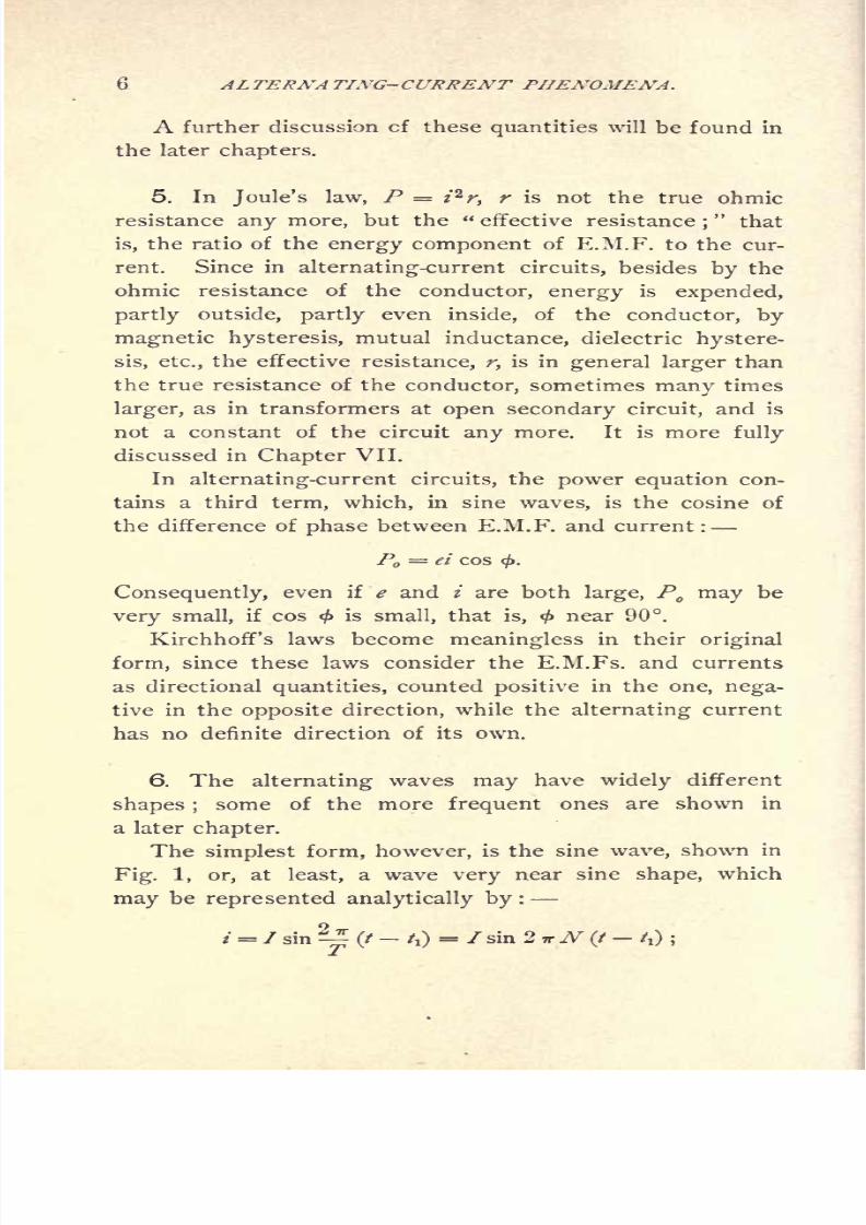
6.
The alternatingwaves
mayhave
widelydifferent
shapes ;some of the more frequent ones are shown in
a later chapter.
The simplest form, however, is the sine wave, shown in
Fig. 1, or, at least, a wave very near sine shape, which
may be represented analytically by :
/ = / sin
^(/
-4)
= /sin 2 TT yV(/
-4)
;

8/2/2019 Charles Steinmetz Theorycalculatio00steiiala
http://slidepdf.com/reader/full/charles-steinmetz-theorycalculatio00steiiala 33/557
8/2/2019 Charles Steinmetz Theorycalculatio00steiiala
http://slidepdf.com/reader/full/charles-steinmetz-theorycalculatio00steiiala 34/557
8 ALTERNA TING-CURRENT PHENOMENA.
where fv 72 ,73 ,
. . . are the maximum values of the differ-
ent components of the wave, fv fv /3
. . . the times, where
the respective components pass the zero value.
The first term, 7X
sin lirN(t tj,
is called the fun-
damental wave, or the first harmonic; the further terms are
called the higher harmonics, or "overtones," in analogy to
the overtones of sound waves. In sin 2 mrN
(t /) is the
thharmonic.
By resolving the sine functions of the time differences,
/ fp t /2
. . .,we reduce the general expression of
the wave to the form :
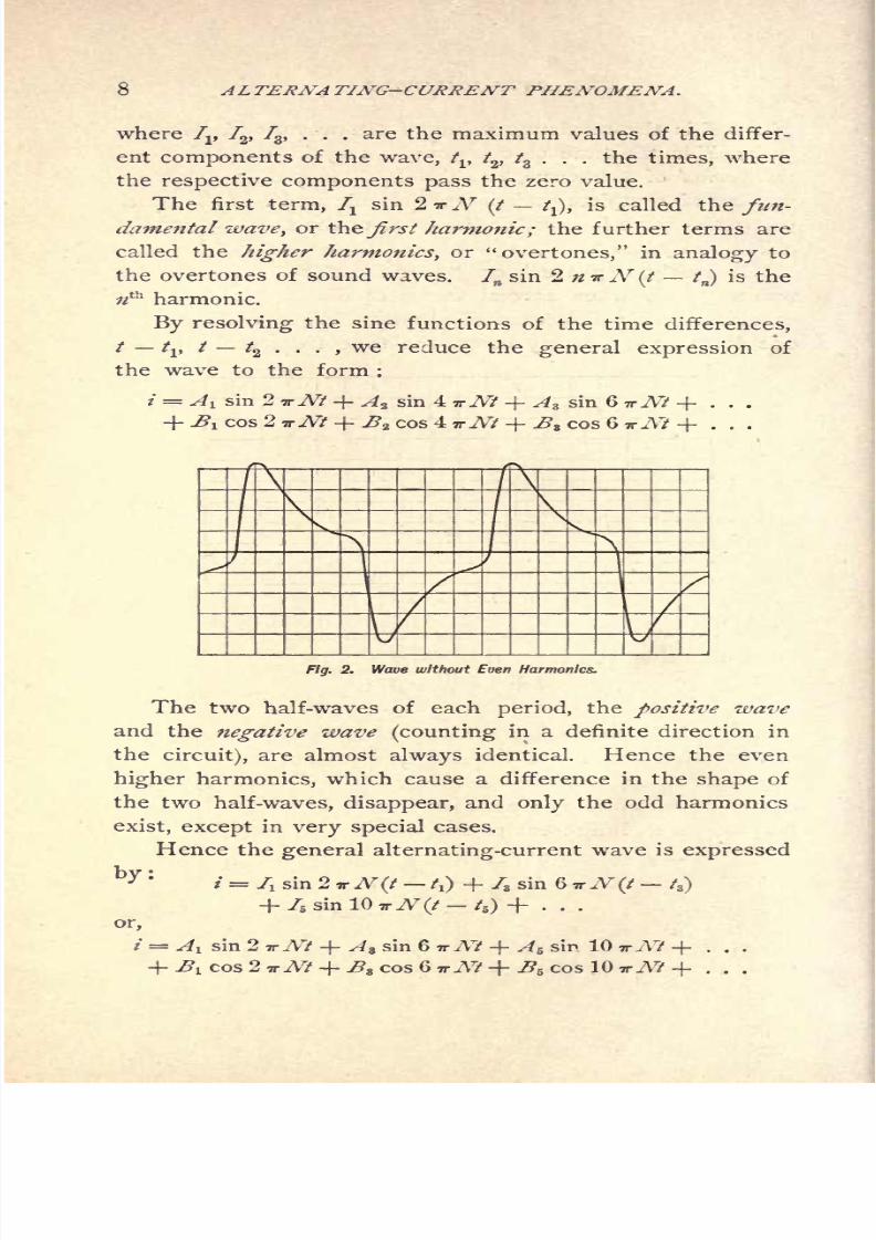
A l sin 2 TrNt + A* sin 4 vNt + Az sin G TTNt + . . .
1 cos27rA?-f^2 cos47rA?-f ^8 cos67ry\7+ . . .
F/g. 2. Wave without Even Harmonics.
The two half-waves of each period, the positive wave
and the negative wave (counting in a definite direction in
thecircuit), are almost always identical. Hence the even
higher harmonics, which cause a difference in the shape of
the two half-waves, disappear, and only the odd harmonics
exist, except in very special cases.
Hence the general alternating-current wave is expressed
ty :
i = 7i sin 2 TTN(t A) + 7, sin 6 TTN (t /3)
+ 75 sin 10 TT A^(/ /5 ) + ...
or,
/ = ^ sin 2 TTA7 + Az sin 6 TTA7 + A& sin 10 wA? + . . .
cos 2 TTNt + ^8 cos 6 TrNt + ^5 cos 10 vNt + . . .

8/2/2019 Charles Steinmetz Theorycalculatio00steiiala
http://slidepdf.com/reader/full/charles-steinmetz-theorycalculatio00steiiala 35/557
8/2/2019 Charles Steinmetz Theorycalculatio00steiiala
http://slidepdf.com/reader/full/charles-steinmetz-theorycalculatio00steiiala 36/557
10 ALTERNA TING-CURRENT PHENOMENA.
sufficient to keep the distortion from sine shape in mind as
a possible disturbing factor, which generally, however, is in
practice negligible perhaps with the only exception of
low-resistance circuits containing large magnetic reactance,
and large condensance in series with each other, so as to
produce resonance effects of these higher harmonics.

8/2/2019 Charles Steinmetz Theorycalculatio00steiiala
http://slidepdf.com/reader/full/charles-steinmetz-theorycalculatio00steiiala 37/557
INSTANTANEOUS AND INTEGRAL VALUES. 11
CHAPTER II
INSTANTANEOUS VALUES AND INTEGRAL VALUES.
8. IN a periodically varying function, as an alternating
current, we have to distinguish between the instantaneous
value, which varies constantly as function of the time, and
the integral value, which characterizes the wave as a whole.
As such integral value, almost exclusively the effective
Fig. 4. Alternating Wave.
value is used, that is, the square root of the mean squares ;
and wherever the intensity of an electric wave is mentioned
without further reference, the effective value is understood.
The maximum value of the wave is of practical interest
only in few cases, and may, besides, be different for the two
half-waves, as in Fig. 3.
As arithmetic mean, or average value, of a wave as in
Figs. 4 and 5, the arithmetical average of all the instan-
taneous values during one complete period is understood.
This arithmetic mean is either = 0, as in Fig. 4, or it
differs
from 0, as. in Fig. 5. In thefirst
case,the wave
is called an alternating wave, in the latter a pttlsatingwave.

8/2/2019 Charles Steinmetz Theorycalculatio00steiiala
http://slidepdf.com/reader/full/charles-steinmetz-theorycalculatio00steiiala 38/557
12 ALTERNA TING-CURRENT PHENOMENA.
Thus, an alternating wave is a wave whose positive
values give the same sum total as the negative values;
that
is, whose two half-waves have in rectangular coordinates
the same area, as shown in Fig. 4.
A pulsating wave is a wave in which one of the half-
waves preponderates, as in Fig. 5.
By electromagnetic induction, pulsating waves are pro-
duced only by commutating and unipolar machines (or by
the superposition of alternating upon direct currents, etc.).
All inductive apparatus without commutation give ex-
clusively alternating waves, because, no matter what con-
Fig. 5. Pulsating Wave.
ditions may exist in the circuit, any line of magnetic force,
which during a complete period is cut by the circuit, and
thereby induces an E.M.F., must during the same period
be cut again in the opposite direction, and thereby induce
the same total amount of E.M.F. (Obviously, this doesnot apply to circuits consisting of different parts movable
with regard to each other, as in unipolar machines.)
In the following we shall almost exclusively consider the
alternating wave, that is the wave whose true arithmetic
mean value = 0.
Frequently, by mean value of an alternating wave, the
average of one half-wave only is denoted, or rather the
8/2/2019 Charles Steinmetz Theorycalculatio00steiiala
http://slidepdf.com/reader/full/charles-steinmetz-theorycalculatio00steiiala 39/557
INSTANTANEOUS AND INTEGRAL VALUES. 13
average of all instantaneous values without regard to their
sign. This mean value is of no practical importance, and
is, besides, in many cases indefinite.
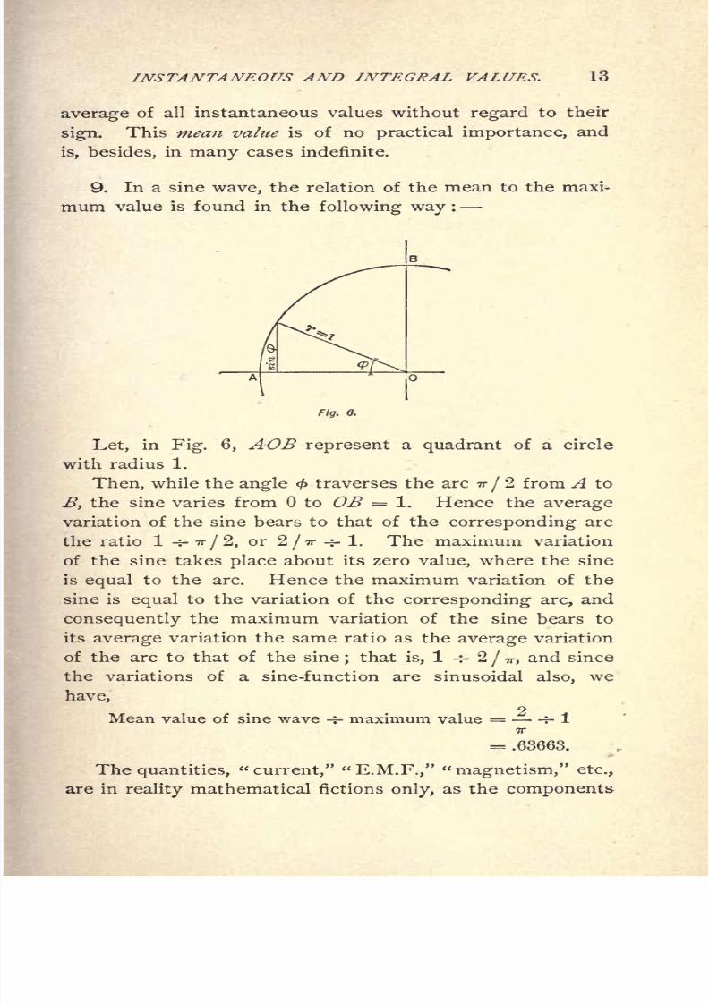
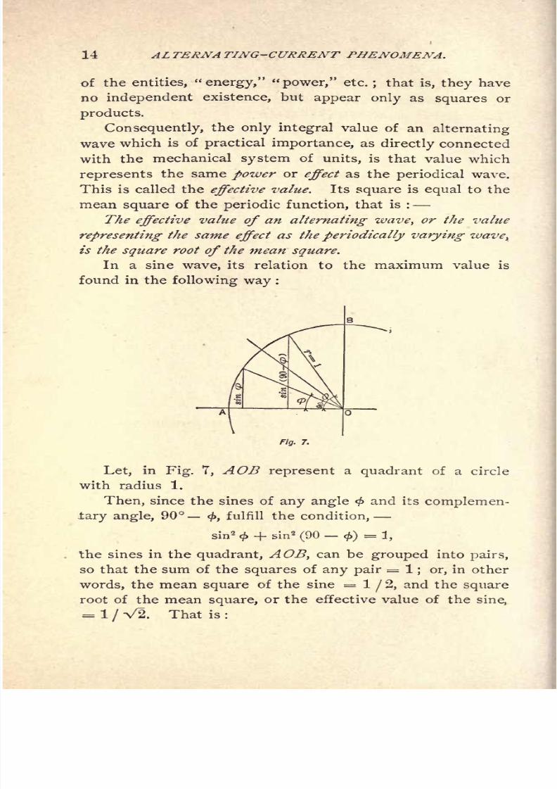
9. In a sine wave, the relation of the mean to the maxi-
mum value is found in the following way :
Fig. 8.
Let, in Fig. 6, AOB represent a quadrant of a circle
with radius 1.
Then, while the angle < traverses the arc -n-
/2 from A to
B, the sine varies from to OB = 1. Hence the average
variation of the sine bears to that of the corresponding arc
the ratio 1 -j- 7r/2,or 2
/TT +- 1. The maximum variation
of the sine takes place about its zero value, where the sine
is equal to the arc. Hence the maximum variation of the
sine is equal to the variation of the corresponding arc, and
consequently the maximum variation of the sine bears to
its
averagevariation the same ratio as the
averagevariation
of the arc to that of the sine;that is, 1 -f- 2
/ 77-,and since
the variations of a sine-function are sinusoidal also, we
have,o
Mean value of sine wave -r- maximum value = -f- 17T
= .63663.
The quantities, "current," "E.M.F.," "magnetism," etc.,
are in mathematical fictions only, as the components
8/2/2019 Charles Steinmetz Theorycalculatio00steiiala
http://slidepdf.com/reader/full/charles-steinmetz-theorycalculatio00steiiala 40/557
8/2/2019 Charles Steinmetz Theorycalculatio00steiiala
http://slidepdf.com/reader/full/charles-steinmetz-theorycalculatio00steiiala 41/557
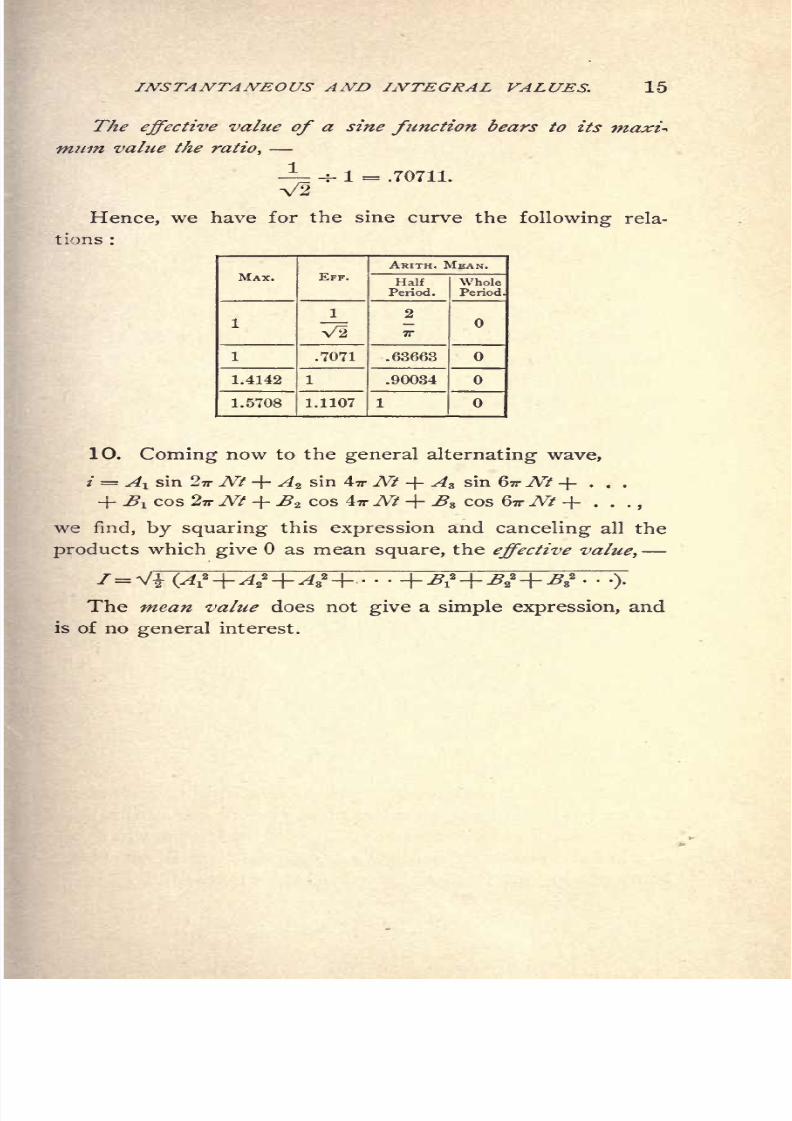
INSTANTANEOUS AND INTEGRAL VALUES. 15
The effective value of a sine function bears to its
mum value the ratio,
1
V2
Hence, we have for the sine curve the following rela-
tions :
1 = .70711.
10. Coming now to the general alternating wave,
/ = Ai sin 27r Nt + Az sin 4-n- Nt + A3 sin GTT Nt + . . .
+ BI cos 2-n-Nt + B* cos TrNt + s cos GTT Nt + . .
we find, by squaring this expression and canceling all the
products which give as mean square, the effective value,
1= V*WThe mean value does not give a simple expression, and
is of no general interest.
8/2/2019 Charles Steinmetz Theorycalculatio00steiiala
http://slidepdf.com/reader/full/charles-steinmetz-theorycalculatio00steiiala 42/557

8/2/2019 Charles Steinmetz Theorycalculatio00steiiala
http://slidepdf.com/reader/full/charles-steinmetz-theorycalculatio00steiiala 43/557

8/2/2019 Charles Steinmetz Theorycalculatio00steiiala
http://slidepdf.com/reader/full/charles-steinmetz-theorycalculatio00steiiala 44/557
18 ALTERNA TING-CURRENT PHENOMENA,
13. If, in a circuit of n turns, the magnetic flux, <t>,
inclosed by the circuit is produced by the current flowing
in the circuit, the ratio
flux X number of turns X 10~ 8
current.
is called the inductance, L, of the circuit, in henrys.
The product of the number of turns, n, into the maxi-
mum flux, <S>, produced by a current of / amperes effective,
or /V2 amperes maximum, is therefore
n =Z/V2 108
;
and consequently the effective E.M.F. of self-inductance is:
E = V2=' 2 TTNLI volts.
The product, x = 2 vNL, is of the dimension of resistance,
and is called the reactance of the circuit;and the E.M.F.
of self-inductance of the circuit, or the reactance voltage, is
E = Ix,
and lags 90 behind the current, since the current is in
phase with the magnetic flux produced by the current,
and the E.M.F. lags 90 behind the magnetic flux. TheE.M.F. lags 90 behind the magnetic flux, as it is propor-
tional to the change in flux;thus it is zero when the mag-
netism is at its maximum value, and a maximum when the
flux passes through zero, where it changes quickest.
8/2/2019 Charles Steinmetz Theorycalculatio00steiiala
http://slidepdf.com/reader/full/charles-steinmetz-theorycalculatio00steiiala 45/557
GRAPHIC REPRESENTA TION, 19
CHAPTER IV.
GRAPHIC REPRESENTATION.
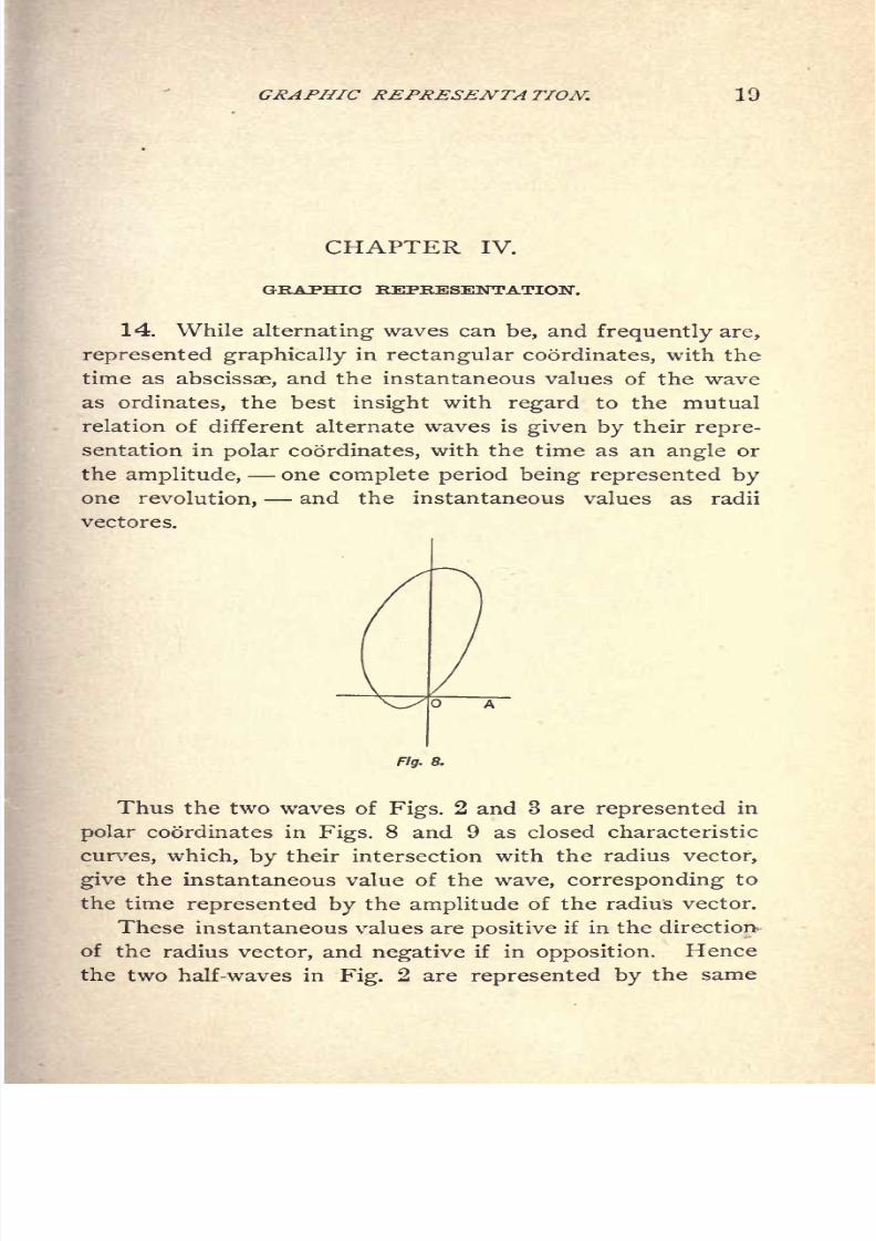
14. While alternating waves can be, and frequently are,
represented graphically in rectangular coordinates, with the
time as abscissae, and the instantaneous values of the wave
as ordinates, the best insight with regard to the mutual
relation of different alternate waves is given by their repre-
sentation in polar coordinates, with the time as an angle or
the amplitude, one complete period being represented byone revolution, and the instantaneous values as radii
vectores.
Fig. 8.
Thus the two waves of Figs. 2 and 3 are represented in
polar coordinates in Figs. 8 and 9 as closed characteristic
curves, which, by their intersection with the radius vector,
give the instantaneous value of the wave, corresponding to
the time represented by the amplitude of the radius vector.
These instantaneous values are positive if in the direction
of the radiusvector, and negative
if inopposition.
Hence
the two half-waves in Fig. 2 are represented by the same
8/2/2019 Charles Steinmetz Theorycalculatio00steiiala
http://slidepdf.com/reader/full/charles-steinmetz-theorycalculatio00steiiala 46/557
8/2/2019 Charles Steinmetz Theorycalculatio00steiiala
http://slidepdf.com/reader/full/charles-steinmetz-theorycalculatio00steiiala 47/557

8/2/2019 Charles Steinmetz Theorycalculatio00steiiala
http://slidepdf.com/reader/full/charles-steinmetz-theorycalculatio00steiiala 48/557
22 ALTERNATING-CURRENT PHENOMEA?A.
OD, the diagonal of a parallelogram with OB and OC as
sides.
For at any time, /, represented by angle <f>= AOX, the
instantaneous values of the three waves, OB, OC, OD, are
their projections upon OX, and the sum of the projections
of OB and OC is equal to the projection of OD;that is, the
instantaneous values of the wave OD are equal to the sum
of the instantaneous values of waves OB and OC.
From the foregoing considerations we have the con-
clusions :
The sine wave is represented graphically in polar coordi-
nates by a vector, which by its length, OC, denotes the in-
Fig. 11.
tensity, and by its amplitude, AOC, the phase, of the sine
wave.
Sine waves are combined or resolved graphically, in polar
coordinates, by the law of parallelogram or tJie polygon of
sine waves.
Kirchhoff's laws now assume, for alternating sine waves,
the form :
a.) The resultant of all the E.M.Fs. in a closed circuit,
as found by the parallelogram of sine waves, is zero if
the counter E.M.Fs. of resistance and of reactance are
included.
b.} The resultant of all the currents flowing towards a

8/2/2019 Charles Steinmetz Theorycalculatio00steiiala
http://slidepdf.com/reader/full/charles-steinmetz-theorycalculatio00steiiala 49/557
8/2/2019 Charles Steinmetz Theorycalculatio00steiiala
http://slidepdf.com/reader/full/charles-steinmetz-theorycalculatio00steiiala 50/557
24 ALTERNA TING-CURRENT PHENOMENA.
of self-induction, an E.M.F. of the value Ix is required,
in phase 90 ahead of the current, hence represented by
vector OEX . Thus resistance consumes E.M.F. in phase,
and reactance an E.M.F. 90 ahead of the current. The
E.M.F. of the generator, E ,has to give the three E.M.Fs.,
E, Er yand Ex, hence it is determined as their resultant.
Combining by the parallelogram law, OEr and OEX , give
OEZ ,
the E.M.F. required to overcome the impedance of
the line, and similarly OEZand OE give OE ,
the E.M.F.
required at the generator side of the line, to yield the
E.M.F. E at the receiving end of the line. Algebraically,
we get from Fig. 12
or, E = VX2
(/*)2 - Jr.
In this instance we have considered the E.M.F. con-
sumed by the resistance (in phase with the current) and
the E.M.F. consumed by the reactance (90 ahead of the
current) as parts, or components, of the impressed E.M.F.,
E,and have derived E by combining Er ,
Ex,and E.
E'.
E?
Fig. 13.
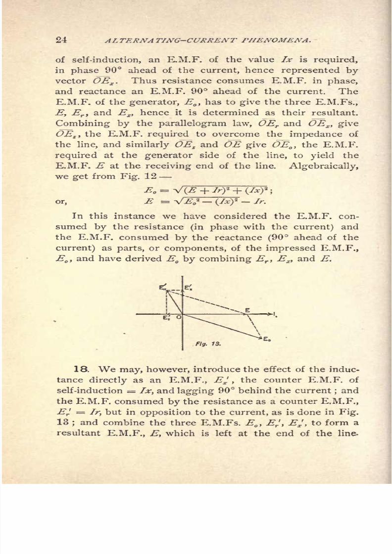
18. We may, however, introduce the effect of the induc-
tance directly as an E.M.F., Ex ,the counter E.M.F. of
self-induction = Ix, and lagging 90 behind the current;and
the E.M.F. consumed by the resistance as a counter E.M.F.,
Ef =Ir, but in opposition to the current, as is done in Fig.
13;and combine the three E.M.Fs. E
,
EJ,
Ex ,to form a
resultant E.M.F., E, which is left at the end of the line-

8/2/2019 Charles Steinmetz Theorycalculatio00steiiala
http://slidepdf.com/reader/full/charles-steinmetz-theorycalculatio00steiiala 51/557

8/2/2019 Charles Steinmetz Theorycalculatio00steiiala
http://slidepdf.com/reader/full/charles-steinmetz-theorycalculatio00steiiala 52/557
26 ALTERNATING-CURRENT PHENOMENA.
Obviously, these counter E.M.Fs. are different from, for
instance, the counter E.M.F. of a synchronous motor, in so
far as they have no independent existence, but exist only
through, and as long as, the current flows. In this respect
they are analogous to the opposing force of friction in
mechanics.
if.
\f
Fig. 15.
19. Coming back to the equation found for the E.M.F.
at the generator end of the line,
we find, as the drop of potential in the line
AE = E E = V />'2 /* 2 E.
This is different from, and less than, the E.M.F. of
impedance
Hence it is wrong to calculate the drop of potential in a
circuit by multiplying the current by the impedance ;and the
drop of potential in the line depends, with a given current
fed over the line into a non-inductive circuit, not only upon
the constants of the line, r and *, but also upon the E.M.F.,
E, at end of line, as can readily be seen from the diagrams.
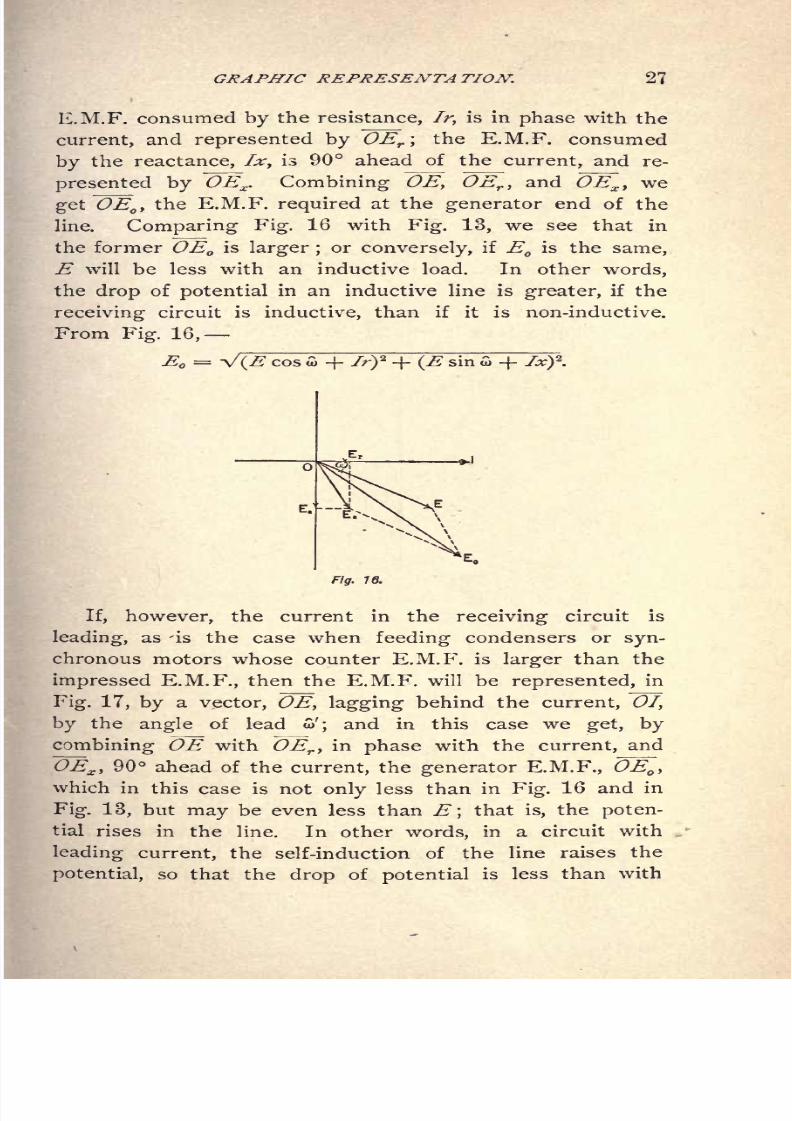
20. If the receiver circuit is inductive, that is, if the
current, /, lags behind the E.M.F., E, by an angle w, and
we choose again as the zero line, the current OI (Fig. 16),
the E.M.F., OE is ahead of the current by angle . The
8/2/2019 Charles Steinmetz Theorycalculatio00steiiala
http://slidepdf.com/reader/full/charles-steinmetz-theorycalculatio00steiiala 53/557
8/2/2019 Charles Steinmetz Theorycalculatio00steiiala
http://slidepdf.com/reader/full/charles-steinmetz-theorycalculatio00steiiala 54/557

8/2/2019 Charles Steinmetz Theorycalculatio00steiiala
http://slidepdf.com/reader/full/charles-steinmetz-theorycalculatio00steiiala 55/557

8/2/2019 Charles Steinmetz Theorycalculatio00steiiala
http://slidepdf.com/reader/full/charles-steinmetz-theorycalculatio00steiiala 56/557

8/2/2019 Charles Steinmetz Theorycalculatio00steiiala
http://slidepdf.com/reader/full/charles-steinmetz-theorycalculatio00steiiala 57/557
8/2/2019 Charles Steinmetz Theorycalculatio00steiiala
http://slidepdf.com/reader/full/charles-steinmetz-theorycalculatio00steiiala 58/557

8/2/2019 Charles Steinmetz Theorycalculatio00steiiala
http://slidepdf.com/reader/full/charles-steinmetz-theorycalculatio00steiiala 59/557

8/2/2019 Charles Steinmetz Theorycalculatio00steiiala
http://slidepdf.com/reader/full/charles-steinmetz-theorycalculatio00steiiala 60/557
8/2/2019 Charles Steinmetz Theorycalculatio00steiiala
http://slidepdf.com/reader/full/charles-steinmetz-theorycalculatio00steiiala 61/557

8/2/2019 Charles Steinmetz Theorycalculatio00steiiala
http://slidepdf.com/reader/full/charles-steinmetz-theorycalculatio00steiiala 62/557

8/2/2019 Charles Steinmetz Theorycalculatio00steiiala
http://slidepdf.com/reader/full/charles-steinmetz-theorycalculatio00steiiala 63/557
8/2/2019 Charles Steinmetz Theorycalculatio00steiiala
http://slidepdf.com/reader/full/charles-steinmetz-theorycalculatio00steiiala 64/557

8/2/2019 Charles Steinmetz Theorycalculatio00steiiala
http://slidepdf.com/reader/full/charles-steinmetz-theorycalculatio00steiiala 65/557
SYMBOLIC METHOD. 39
E.M.F. of self-induction, is the product of the current
and reactance, and lags 90 behind the current ;it is,
therefore, represented by the expression
The E.M.F. required to overcome the reactance is con- ,
sequently 90 ahead of the current (or,as usually expressed,-**
the current lags 90 behind the E.M.F.), and represented
by the expression
jxl= jxi -f- xi'.
Hence, the E.M.F. required to overcome the resistance,
r, and the reactance, x, is
that is
Z= r
jxis the
expression ofthe
impedance of thecir-
cuit, in complex quantities.
Hence, if / = i -\-ji' is the current, the E.M.F. required
to overcome the impedance, Z = r jx, is
hence, sincey"2 = 1
or, if E = e -\- je' is the impressed E.M.F., and Z = r jxthe impedance, the current flowing through the circuit is :
or, multiplying numerator and denominator by(r+jx)
to
eliminate the imaginary from the denominator, we have
T_
or, if E = e -\-je' is the impressed E.M.F., and 7 = i
'
-\- ji'
the current flowing in the circuit, its impedance is
+./>') O'-./*'') '+^*''.
' ~ ei'
'
8/2/2019 Charles Steinmetz Theorycalculatio00steiiala
http://slidepdf.com/reader/full/charles-steinmetz-theorycalculatio00steiiala 66/557
40 ALTERNATING-CURRENT PHENOMENA.
30. If C is the capacity of a condenser in series in
a circuit of current I = i + //', the E.M.F. impressed upon
the terminals of the condenser is E = -- ,90 behind
the current;and may be represented by
--,or jx^ /,
where x^=- is the capacity reactance or condensatice
2 TTNC
of the condenser.
Capacity reactance is of opposite sign to magnetic re-
actance;both may be combined in the name reactance.
We therefore have the conclusion that
If r = resistance and L = inductance,
then x = 2 ITNL = magnetic reactance.
If C = capacity, x^ =
-= capacity reactance, or conden-
sance;
Z = r j (x JCi),is the impedance of the circuit
Ohm's law is then reestablished as follows :
, -, .
The more general form gives not only the intensity of
the wave, but also its phase, as expressed in complex
quantities.
31. Since the combination of sine waves takes place by
the addition of their symbolic expressions, Kirchhoff's laws
are now reestablished in their original form :
a.} The sum of all the E.M.Fs. acting in a closed cir-
cuit equals zero, if they are expressed by complex quanti-
ties, and if the resistance and reactance E.M.Fs. are also
considered as counter E.M.Fs.
b.) The sum of all the currents flowing towards a dis-
tributing point is zero, if the currents are expressed as
complex quantities.
8/2/2019 Charles Steinmetz Theorycalculatio00steiiala
http://slidepdf.com/reader/full/charles-steinmetz-theorycalculatio00steiiala 67/557

8/2/2019 Charles Steinmetz Theorycalculatio00steiiala
http://slidepdf.com/reader/full/charles-steinmetz-theorycalculatio00steiiala 68/557
8/2/2019 Charles Steinmetz Theorycalculatio00steiiala
http://slidepdf.com/reader/full/charles-steinmetz-theorycalculatio00steiiala 69/557

8/2/2019 Charles Steinmetz Theorycalculatio00steiiala
http://slidepdf.com/reader/full/charles-steinmetz-theorycalculatio00steiiala 70/557
8/2/2019 Charles Steinmetz Theorycalculatio00steiiala
http://slidepdf.com/reader/full/charles-steinmetz-theorycalculatio00steiiala 71/557
8/2/2019 Charles Steinmetz Theorycalculatio00steiiala
http://slidepdf.com/reader/full/charles-steinmetz-theorycalculatio00steiiala 72/557
8/2/2019 Charles Steinmetz Theorycalculatio00steiiala
http://slidepdf.com/reader/full/charles-steinmetz-theorycalculatio00steiiala 73/557
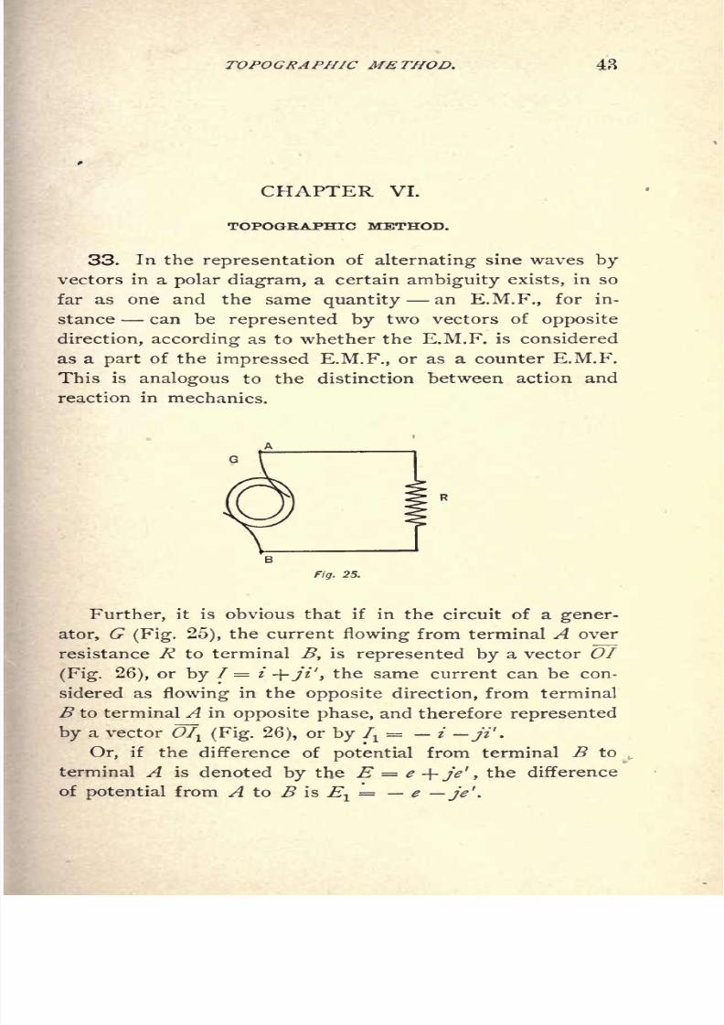
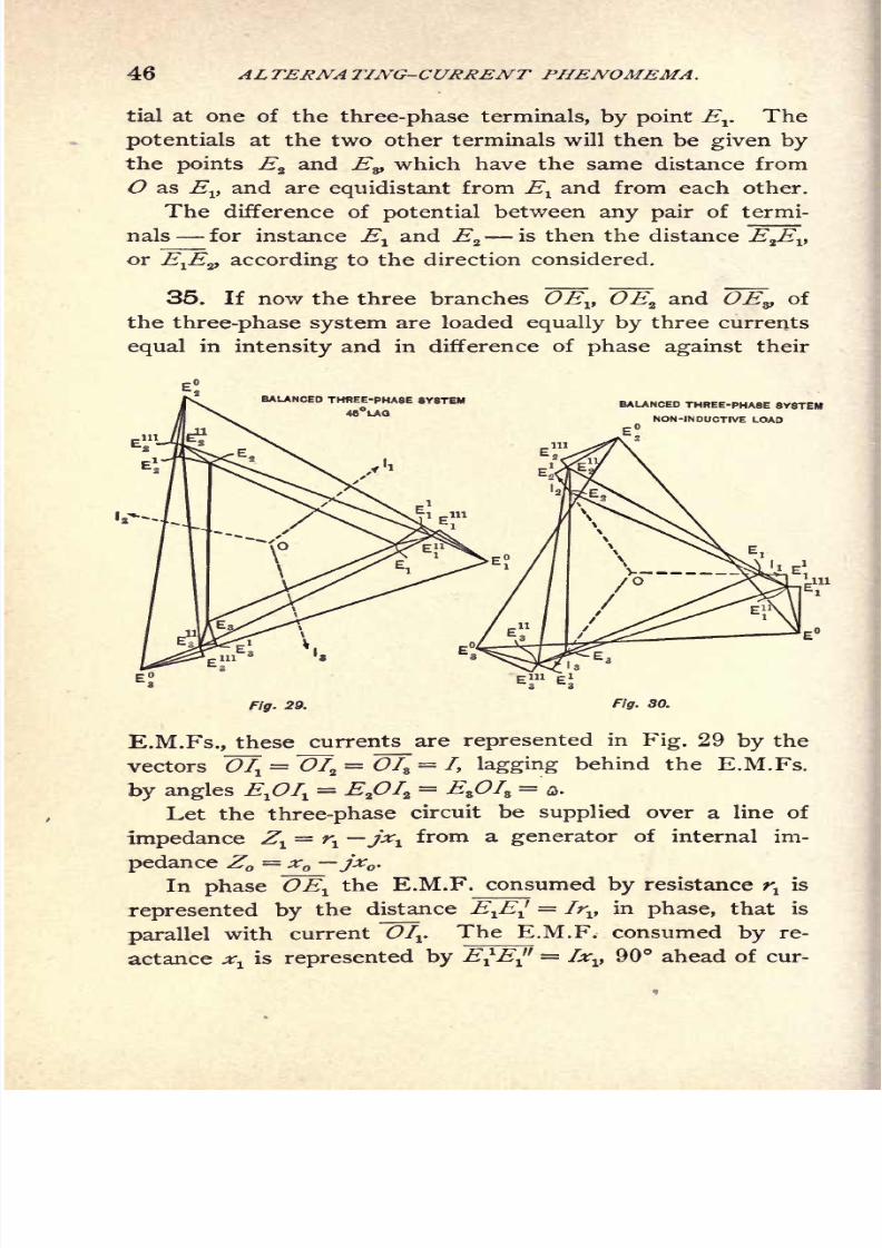
TOPOGRAPHIC METHOD. 47
rent OIr The same applies to the other two phases, and
it thus follows that to produce the E.M.F. triangle E^E^E^at the terminals of the consumer's circuit, the E.M.F. tri-
angle E^E^E? is required at the generator terminals.
Repeating the same operation for the internal impedance
of the generator we get E"E'" = Iroi
and parallel to OIVE'"E = Ixoy and 90 ahead of ~OTV and thus as triangle of
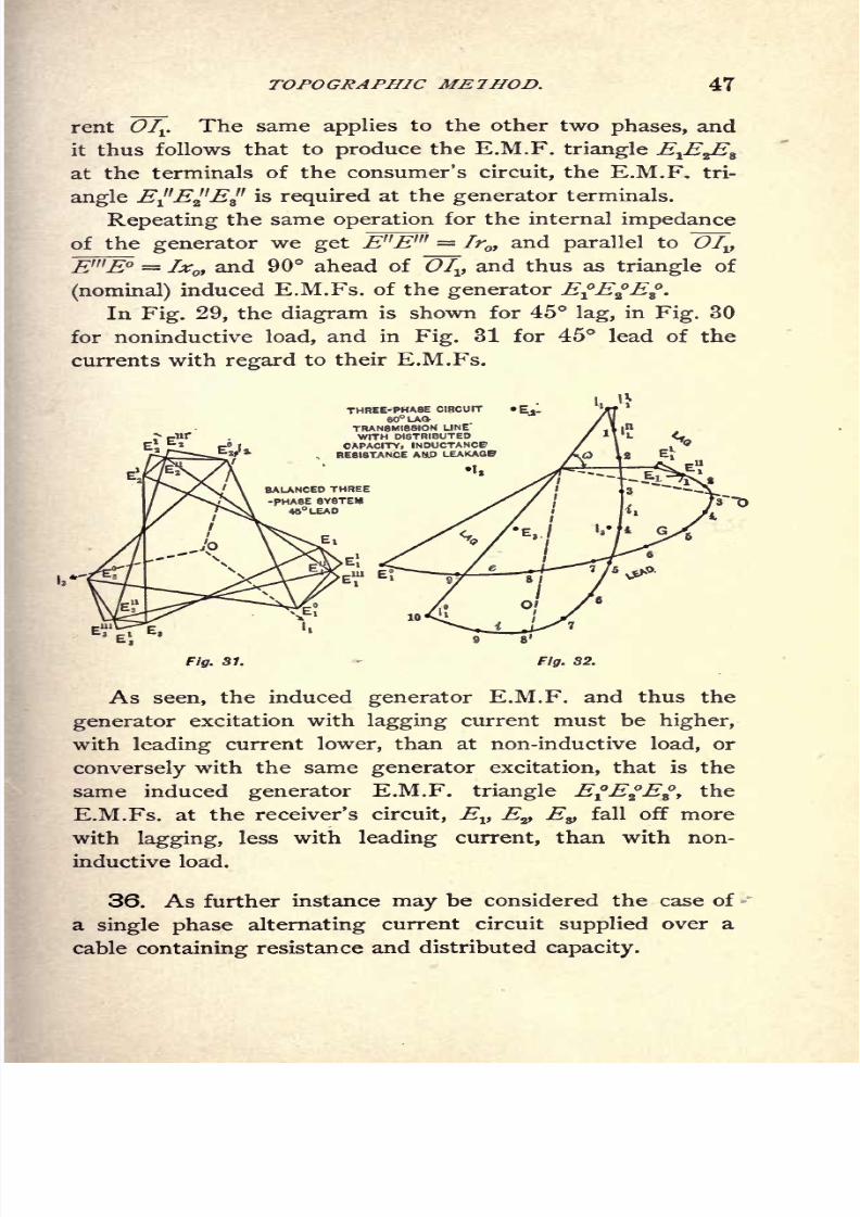
(nominal) induced E.M.Fs. of the generator EEE.In Fig. 29, the diagram is shown for 45 lag, in Fig. 30
for noninductive load, and in Fig. 31 for 45 lead of the
currents with regard to their E.M.Fs.
BALANCED THREE
-PHASE SYSTEM
45 LEAD
THREE-PHASE CIRCUIT
80LATRANSMISSION LINE'
WITH DISTRIBUTED
CAPACITY, INDUCTANCBRESISTANCE AUD LEAKAQB
I,
Fig. 31. Fig. 32.
As seen, the induced generator E.M.F. and thus the
generator excitation with lagging current must be higher,
with leading current lower, than at non-inductive load, or
conversely with the same generator excitation, that is the
same induced generator E.M.F. triangle EEE, the
E.M.Fs. at the receiver's circuit, Ev Ez,E9 fall off more
with lagging, less with leading current, than with non-
inductive load.
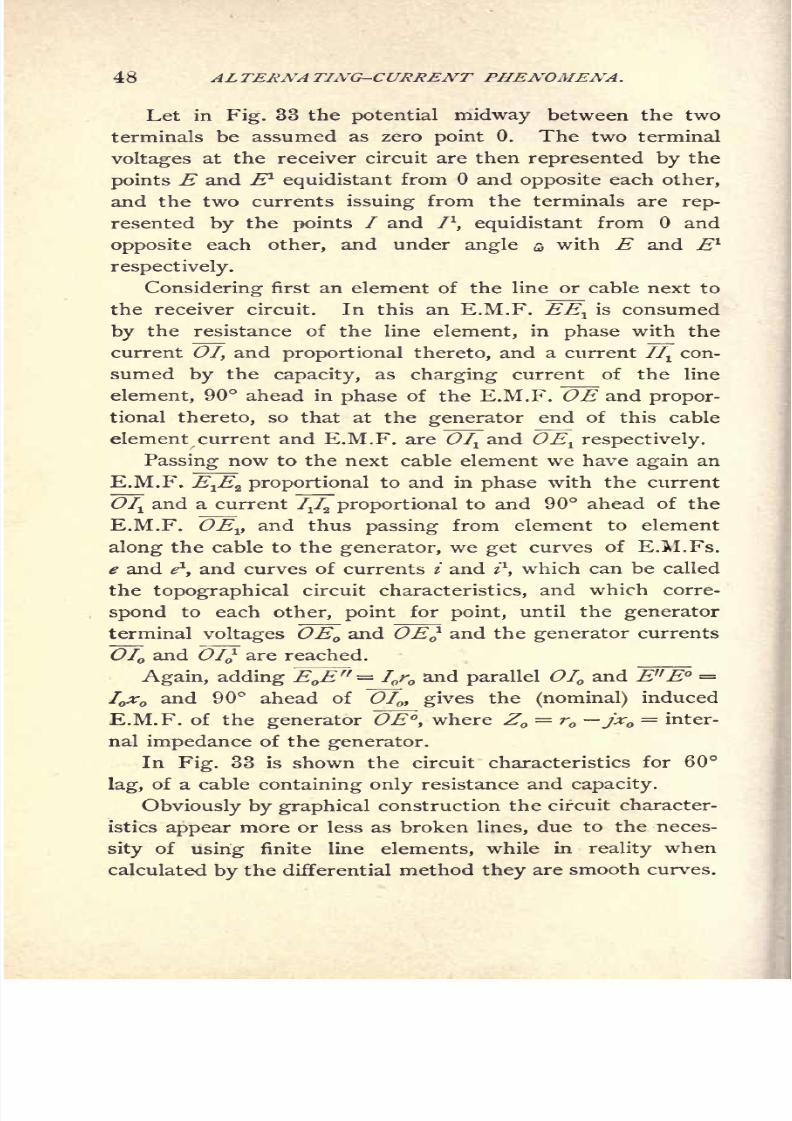
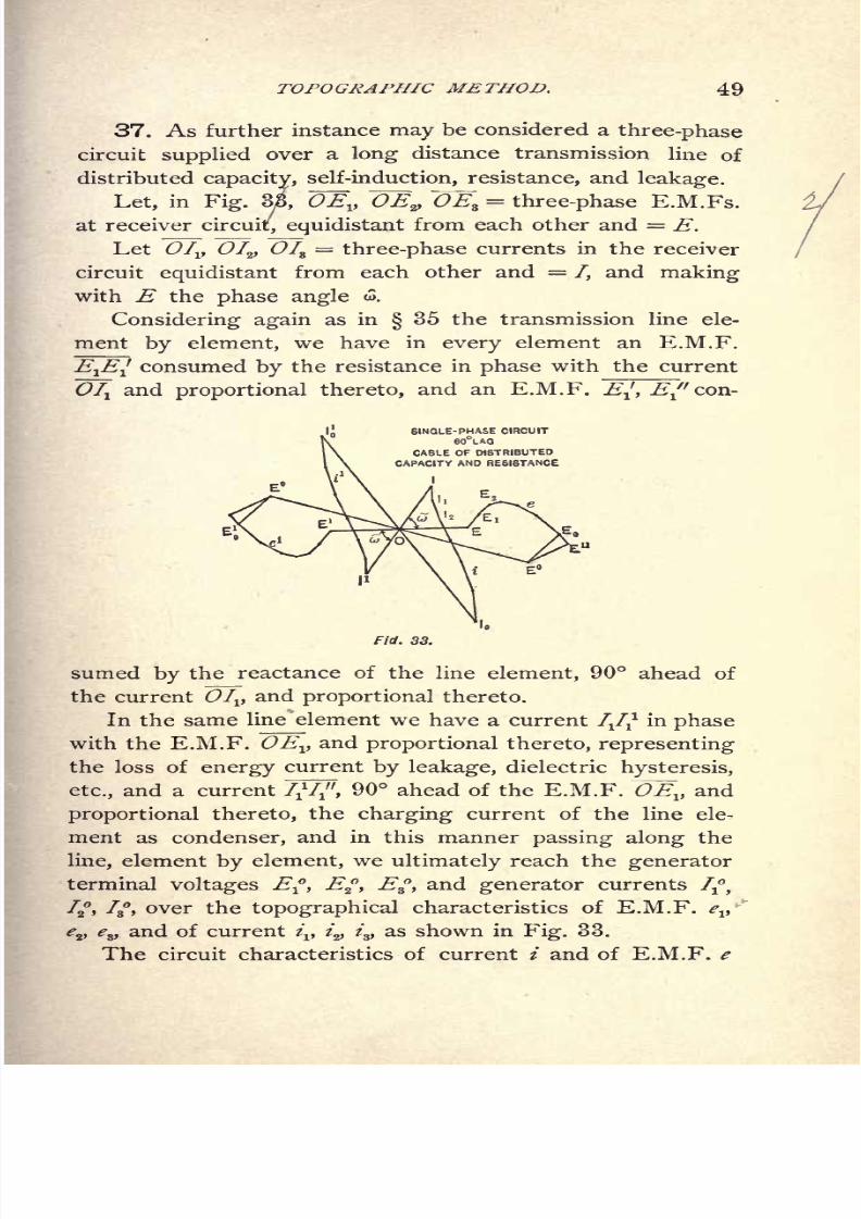
36. As further instance may be considered the case of
a single phase alternating current circuit supplied over a
cable containing resistance and distributed capacity.
8/2/2019 Charles Steinmetz Theorycalculatio00steiiala
http://slidepdf.com/reader/full/charles-steinmetz-theorycalculatio00steiiala 74/557
8/2/2019 Charles Steinmetz Theorycalculatio00steiiala
http://slidepdf.com/reader/full/charles-steinmetz-theorycalculatio00steiiala 75/557

8/2/2019 Charles Steinmetz Theorycalculatio00steiiala
http://slidepdf.com/reader/full/charles-steinmetz-theorycalculatio00steiiala 76/557
8/2/2019 Charles Steinmetz Theorycalculatio00steiiala
http://slidepdf.com/reader/full/charles-steinmetz-theorycalculatio00steiiala 77/557

8/2/2019 Charles Steinmetz Theorycalculatio00steiiala
http://slidepdf.com/reader/full/charles-steinmetz-theorycalculatio00steiiala 78/557

8/2/2019 Charles Steinmetz Theorycalculatio00steiiala
http://slidepdf.com/reader/full/charles-steinmetz-theorycalculatio00steiiala 79/557
8/2/2019 Charles Steinmetz Theorycalculatio00steiiala
http://slidepdf.com/reader/full/charles-steinmetz-theorycalculatio00steiiala 80/557
8/2/2019 Charles Steinmetz Theorycalculatio00steiiala
http://slidepdf.com/reader/full/charles-steinmetz-theorycalculatio00steiiala 81/557
8/2/2019 Charles Steinmetz Theorycalculatio00steiiala
http://slidepdf.com/reader/full/charles-steinmetz-theorycalculatio00steiiala 82/557
56 AL TERNA TING-CURRENT PHENOMENA.
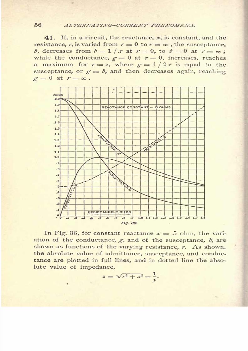
41. If, in a circuit, the reactance, *-, is constant, and the
resistance, r, is varied from r = to r = oo , the susceptance,
b, decreases from b = 1/x at r = 0, to # = at r = cc ;
while the conductance, g at r = 0, increases, reaches
a maximum for r = x, where g 1/2 r is equal to the
susceptance, or g = b, and then decreases again, reaching
g = at r = oo .
In Fig. 36, for constant reactance ^- = .5 ohm, the vari-
ation of the conductance, g, and of the susceptance, b, are
shown as functions of the varying resistance, r. As shown,
the absolute value of admittance, susceptance, and conduc-
tance are plotted in full lines, and in dotted line the abso-
lute value of impedance,

8/2/2019 Charles Steinmetz Theorycalculatio00steiiala
http://slidepdf.com/reader/full/charles-steinmetz-theorycalculatio00steiiala 83/557
ADMITTANCE, CONDUCTANCE, SUSCEPTANCE. 57
Obviously, if the resistance, r, is constant, and the reac-
tance, x, is varied, the values of conductance and susceptance
are merely exchanged, the conductance decreasing steadily
from g = 1/r to 0, and the susceptance passing from at
x = to the maximum, b = 1/2 r = g =1 /'2 x at x = r,
and to b = at x = GO .
The resistance, r, and the reactance, x, vary as functions
of the conductance, g, and the susceptance, b, in the same
manner as g and b vary as functions of r and x.
The sign in the complex expression of admittance is
always opposite to that of impedance ;this is obvious, since
if the current lags behind the E.M.F., the E.M.F. leads the
current, and conversely.
We can thus express Ohm's law in the two forms
E = IZ,
I =Y,and therefore
The joint impedance of a number of series-connected im-
pedances is equal to the sum. of the individual impedances ;
the joint admittance of a number ofparallel-connected admit-
tances, if expressed in complex quantities, is equal to the sum
ofthe individual admittances. In
diagrammatic represen-tation, combination by the parallelogram law takes the place
of addition of the complex quantities.

8/2/2019 Charles Steinmetz Theorycalculatio00steiiala
http://slidepdf.com/reader/full/charles-steinmetz-theorycalculatio00steiiala 84/557
8/2/2019 Charles Steinmetz Theorycalculatio00steiiala
http://slidepdf.com/reader/full/charles-steinmetz-theorycalculatio00steiiala 85/557
8/2/2019 Charles Steinmetz Theorycalculatio00steiiala
http://slidepdf.com/reader/full/charles-steinmetz-theorycalculatio00steiiala 86/557
8/2/2019 Charles Steinmetz Theorycalculatio00steiiala
http://slidepdf.com/reader/full/charles-steinmetz-theorycalculatio00steiiala 87/557
8/2/2019 Charles Steinmetz Theorycalculatio00steiiala
http://slidepdf.com/reader/full/charles-steinmetz-theorycalculatio00steiiala 88/557

8/2/2019 Charles Steinmetz Theorycalculatio00steiiala
http://slidepdf.com/reader/full/charles-steinmetz-theorycalculatio00steiiala 89/557
8/2/2019 Charles Steinmetz Theorycalculatio00steiiala
http://slidepdf.com/reader/full/charles-steinmetz-theorycalculatio00steiiala 90/557
8/2/2019 Charles Steinmetz Theorycalculatio00steiiala
http://slidepdf.com/reader/full/charles-steinmetz-theorycalculatio00steiiala 91/557

8/2/2019 Charles Steinmetz Theorycalculatio00steiiala
http://slidepdf.com/reader/full/charles-steinmetz-theorycalculatio00steiiala 92/557
8/2/2019 Charles Steinmetz Theorycalculatio00steiiala
http://slidepdf.com/reader/full/charles-steinmetz-theorycalculatio00steiiala 93/557
8/2/2019 Charles Steinmetz Theorycalculatio00steiiala
http://slidepdf.com/reader/full/charles-steinmetz-theorycalculatio00steiiala 94/557

8/2/2019 Charles Steinmetz Theorycalculatio00steiiala
http://slidepdf.com/reader/full/charles-steinmetz-theorycalculatio00steiiala 95/557
8/2/2019 Charles Steinmetz Theorycalculatio00steiiala
http://slidepdf.com/reader/full/charles-steinmetz-theorycalculatio00steiiala 96/557

8/2/2019 Charles Steinmetz Theorycalculatio00steiiala
http://slidepdf.com/reader/full/charles-steinmetz-theorycalculatio00steiiala 97/557
8/2/2019 Charles Steinmetz Theorycalculatio00steiiala
http://slidepdf.com/reader/full/charles-steinmetz-theorycalculatio00steiiala 98/557
8/2/2019 Charles Steinmetz Theorycalculatio00steiiala
http://slidepdf.com/reader/full/charles-steinmetz-theorycalculatio00steiiala 99/557

8/2/2019 Charles Steinmetz Theorycalculatio00steiiala
http://slidepdf.com/reader/full/charles-steinmetz-theorycalculatio00steiiala 100/557
8/2/2019 Charles Steinmetz Theorycalculatio00steiiala
http://slidepdf.com/reader/full/charles-steinmetz-theorycalculatio00steiiala 101/557
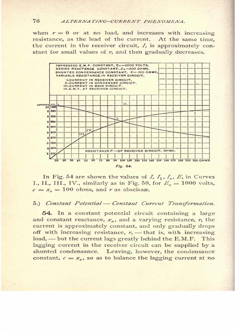
RESISTANCE, INDUCTANCE, CAPACITY. 75
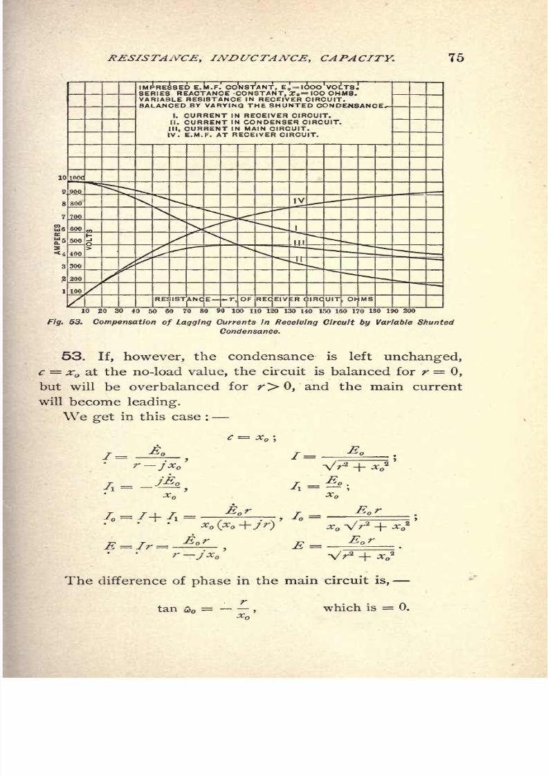
IMPRESSED E.M.F. CONSTANT, E = IOOO VOLTS.SERIES REACTANCE CONSTANT, X = IOO OHMS.
VARIABLE RESISTANCE IN RECEIVER CIRCUIT.BALANCED BY VARYING THE SHUNTED CONDENSANCE,
I. CURRENT IN RECEIVER CIRCUIT.
II. CURRENT IN CONDENSER CIRCUIT.
III. CURRENT IN MAIN CIRCUIT.
JV. E.M.F. AT RECEIVER CIRCUIT.
100 /r. OF RECEIVER CIRCUIT OHMS
10 20 30 40 50 60 70 80 90 100 110 120 130 HO 150 160 170 180 190 200
Fig. 53. Compensation of Lagging Currents in Receiving Circuit by Variable Shunted
Condensance.
53. If, however, the condensance is left unchanged,
c = x at the no-load value, the circuit is balanced for r = 0,
but will be overbalanced for r> 0, and the main current
will become leading.
We get in this case :
r-jx
The difference of phase in the main circuit is,
tan u>=
,which is = 0.
8/2/2019 Charles Steinmetz Theorycalculatio00steiiala
http://slidepdf.com/reader/full/charles-steinmetz-theorycalculatio00steiiala 102/557
8/2/2019 Charles Steinmetz Theorycalculatio00steiiala
http://slidepdf.com/reader/full/charles-steinmetz-theorycalculatio00steiiala 103/557

8/2/2019 Charles Steinmetz Theorycalculatio00steiiala
http://slidepdf.com/reader/full/charles-steinmetz-theorycalculatio00steiiala 104/557

8/2/2019 Charles Steinmetz Theorycalculatio00steiiala
http://slidepdf.com/reader/full/charles-steinmetz-theorycalculatio00steiiala 105/557

8/2/2019 Charles Steinmetz Theorycalculatio00steiiala
http://slidepdf.com/reader/full/charles-steinmetz-theorycalculatio00steiiala 106/557

8/2/2019 Charles Steinmetz Theorycalculatio00steiiala
http://slidepdf.com/reader/full/charles-steinmetz-theorycalculatio00steiiala 107/557
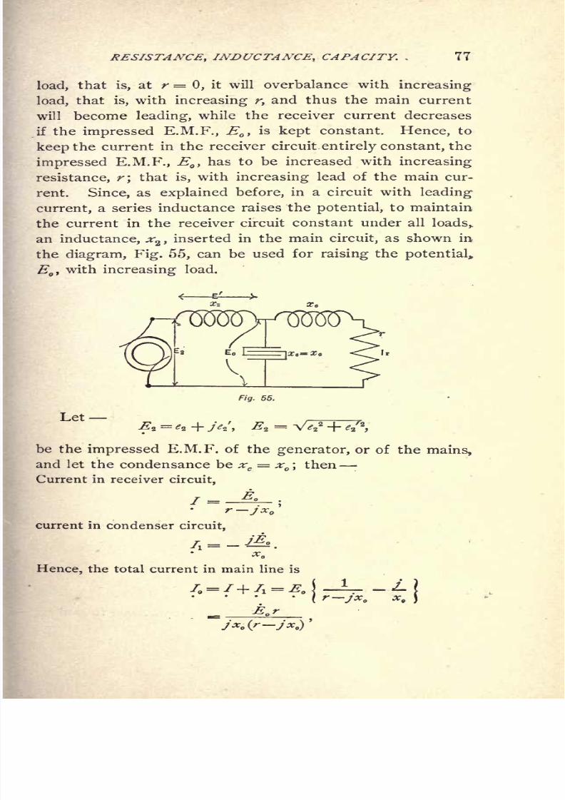
RESISTANCE, INDUCTANCE, CAPACITY. 81
56. In practice, the power consumed in the main circuit
will be larger than the power delivered to the receiver cir-
cuit, due to the unavoidable losses of power in the induc-
tances and condensances.
F/3.
50. Constant-Potential Constant-Current Transformation.
Let
ri= 2 ohms = effective resistance of condensance
;
r = 3 ohms = effective resistance of each of the inductances.
We then have :
Power consumed in condensance, I* r = 200 + .02 r2
;
power consumed by first inductance, 72r = 300
;
power consumed by second inductance, / 2 r = .03 r*.
Hence, the total loss of energy is 500 + -05 r2
;
output of system,/ 2 r = 100 r
input, 500 + 100 r -\
effidenCy'
500 + 1WMIt follows that the main current, f
,increases slightly
by the amount necessary to supply the losses of energy
8/2/2019 Charles Steinmetz Theorycalculatio00steiiala
http://slidepdf.com/reader/full/charles-steinmetz-theorycalculatio00steiiala 108/557
8/2/2019 Charles Steinmetz Theorycalculatio00steiiala
http://slidepdf.com/reader/full/charles-steinmetz-theorycalculatio00steiiala 109/557
RESISTANCE OF TRANSMISSION LINES.
CHAPTER IX.
RESISTANCE AND REACTANCE OF TRANSMISSION LINES.
57. In alternating-current circuits, E.M.F. is consumed
in the feeders of distributing networks, and in the lines of
long-distance transmissions, not only by the resistance, but
also by the reactance, of the line. The E.M.F. consumed by
the resistance is in phase, while the E.M.F. consumed by the
reactance is in quadrature, with the current. Hence their
influence upon the E.M.F. at the receiver circuit depends
upon the difference of phase between the current and the
E.M.F. in that circuit. As discussed before, the drop of
potential due to the resistance is a maximum when the
receiver current is in phase, a minimum when it is in
quadrature, with the E.M.F. The change of potential due
to line reactance is small if the current is in phase with
the E.M.F., while a drop of potential is produced with a
lagging, and a rise of potential with a leading, current in
the receiver circuit.
Thus the change of potential due to a line of given re-
sistance and inductance depends upon the phase difference
in the receiver circuit, and can be varied and controlled
by varying
this
phase
difference;that is,
by varying
the
admittance, Y = g -f jb, of the receiver circuit.
The conductance, gyof the receiver circuit depends upon
the consumption of power, that is, upon the load on the
circuit, and thus cannot be varied for the purpose of reg-
ulation. Its susceptance, b, however, can be changed by
shunting the circuit with a reactance, and will be increased
by a shunted inductance, and decreased by a shunted con-
densance. for the of the
8/2/2019 Charles Steinmetz Theorycalculatio00steiiala
http://slidepdf.com/reader/full/charles-steinmetz-theorycalculatio00steiiala 110/557
8/2/2019 Charles Steinmetz Theorycalculatio00steiiala
http://slidepdf.com/reader/full/charles-steinmetz-theorycalculatio00steiiala 111/557
8/2/2019 Charles Steinmetz Theorycalculatio00steiiala
http://slidepdf.com/reader/full/charles-steinmetz-theorycalculatio00steiiala 112/557

8/2/2019 Charles Steinmetz Theorycalculatio00steiiala
http://slidepdf.com/reader/full/charles-steinmetz-theorycalculatio00steiiala 113/557
8/2/2019 Charles Steinmetz Theorycalculatio00steiiala
http://slidepdf.com/reader/full/charles-steinmetz-theorycalculatio00steiiala 114/557

8/2/2019 Charles Steinmetz Theorycalculatio00steiiala
http://slidepdf.com/reader/full/charles-steinmetz-theorycalculatio00steiiala 115/557

8/2/2019 Charles Steinmetz Theorycalculatio00steiiala
http://slidepdf.com/reader/full/charles-steinmetz-theorycalculatio00steiiala 116/557
8/2/2019 Charles Steinmetz Theorycalculatio00steiiala
http://slidepdf.com/reader/full/charles-steinmetz-theorycalculatio00steiiala 117/557
8/2/2019 Charles Steinmetz Theorycalculatio00steiiala
http://slidepdf.com/reader/full/charles-steinmetz-theorycalculatio00steiiala 118/557

8/2/2019 Charles Steinmetz Theorycalculatio00steiiala
http://slidepdf.com/reader/full/charles-steinmetz-theorycalculatio00steiiala 119/557
8/2/2019 Charles Steinmetz Theorycalculatio00steiiala
http://slidepdf.com/reader/full/charles-steinmetz-theorycalculatio00steiiala 120/557
8/2/2019 Charles Steinmetz Theorycalculatio00steiiala
http://slidepdf.com/reader/full/charles-steinmetz-theorycalculatio00steiiala 121/557

8/2/2019 Charles Steinmetz Theorycalculatio00steiiala
http://slidepdf.com/reader/full/charles-steinmetz-theorycalculatio00steiiala 122/557
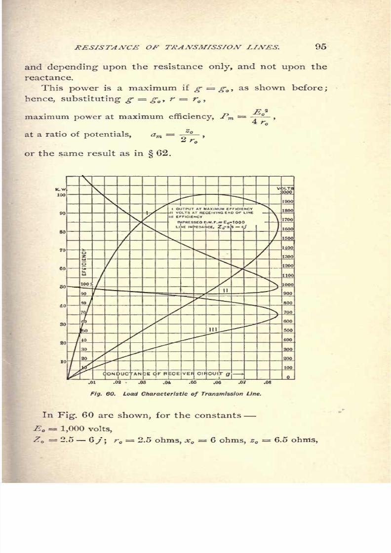
96 ALTERNATING-CURRENT PHENOMENA.
andwith
the variableconductances, g,
of the receiver circuit
as abscissae, the
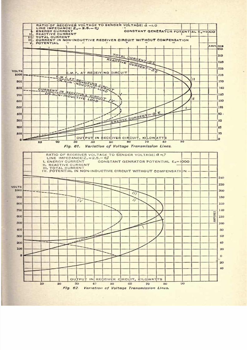
Output at maximum efficiency, (Curve I.) ;
Volts at receiving end of line, (Curve II.) ;
Efficiency=
, (Curve III.).r + r
4.)Control of Receiver Voltage by Shunted Snsceptance.
66. By varying the susceptance of the receiver circuit,
the potential at the receiver terminals is varied greatly.
Therefore, since the susceptance of the receiver circuit can
be varied at will, it is possible, at a constant generator
E.M.F., to adjust the receiver susceptance so as to keep
the potential constant at the receiver end of the line, or to
vary it in any desired manner, and independently of the
generator potential, within certain limits.
The ratio of E.M.Fs. is
If at constant generator potential E ,the receiver potential
E shall be constant,a constant
;
hence,
#2'
or, expanding,
which is the value of the susceptance, b, as a function of
the receiver conductance, that is, of the load, which is
required to yield constant potential, aE, at the receiver
circuit.
For increasing g, that is, for increasing load, a point is
reached, where, in the expression
b = -
8/2/2019 Charles Steinmetz Theorycalculatio00steiiala
http://slidepdf.com/reader/full/charles-steinmetz-theorycalculatio00steiiala 123/557
8/2/2019 Charles Steinmetz Theorycalculatio00steiiala
http://slidepdf.com/reader/full/charles-steinmetz-theorycalculatio00steiiala 124/557
8/2/2019 Charles Steinmetz Theorycalculatio00steiiala
http://slidepdf.com/reader/full/charles-steinmetz-theorycalculatio00steiiala 125/557
8/2/2019 Charles Steinmetz Theorycalculatio00steiiala
http://slidepdf.com/reader/full/charles-steinmetz-theorycalculatio00steiiala 126/557
8/2/2019 Charles Steinmetz Theorycalculatio00steiiala
http://slidepdf.com/reader/full/charles-steinmetz-theorycalculatio00steiiala 127/557

8/2/2019 Charles Steinmetz Theorycalculatio00steiiala
http://slidepdf.com/reader/full/charles-steinmetz-theorycalculatio00steiiala 128/557
8/2/2019 Charles Steinmetz Theorycalculatio00steiiala
http://slidepdf.com/reader/full/charles-steinmetz-theorycalculatio00steiiala 129/557

8/2/2019 Charles Steinmetz Theorycalculatio00steiiala
http://slidepdf.com/reader/full/charles-steinmetz-theorycalculatio00steiiala 130/557

8/2/2019 Charles Steinmetz Theorycalculatio00steiiala
http://slidepdf.com/reader/full/charles-steinmetz-theorycalculatio00steiiala 131/557

8/2/2019 Charles Steinmetz Theorycalculatio00steiiala
http://slidepdf.com/reader/full/charles-steinmetz-theorycalculatio00steiiala 132/557
106 .ALTERNATING-CURRENT PHENOMENA.
2.) Primary electric currents, as,
a.} Leakage or escape of current through the insu-
lation, brush discharge ; b.) Eddy currents in
the conductor or unequal current distribution.
3.) Secondary or induced currents, as,
a.) Eddy or Foucault currents in surrounding mag-
netic materials; b.} Eddy or Foucault currents
in surrounding conducting materials; c.}
Sec-
ondary currents of mutual inductance in neigh-
boring circuits.
4.)Induced electric charges, electrostatic influence.
While all these losses can be included in the terms effec-
tive resistance, etc., only the magnetic hysteresis and the
eddy currents in the iron will form the subject of what fol-
lows, since they are the most frequent and important sources
of energy loss.
Magnetic Hysteresis.
74. In an alternating-current circuit surrounded by iron
or other magnetic material, energy is expended outside of
the conductor in the iron, by a kind of molecular friction,
which, when the energy is supplied electrically, appears as
magnetic hysteresis, and is caused by the cyclic reversals of
magnetic flux in the iron in the alternating magnetic field.
To examine this phenomenon, first a circuit may be con-
sidered, of very high inductance, but negligible true ohmic
resistance;that is, a circuit entirely surrounded by iron, as,
for instance, the primary circuit of an alternating-current
transformer with open secondary circuit.
The wave of current produces in the iron an alternating
magnetic flux which induces in the electric circuit an E.M.F.,
the counter E.M.F. of self-induction. If the ohmic re-
sistance is negligible, that is, practically no E.M.F. con-
sumed by the resistance, all the impressed E.M.F. must be
consumed
by
the counter E.M.F. of self-induction, that is,
the counter E.M.F. equals the impressed E.M.F.; hence, if
8/2/2019 Charles Steinmetz Theorycalculatio00steiiala
http://slidepdf.com/reader/full/charles-steinmetz-theorycalculatio00steiiala 133/557
8/2/2019 Charles Steinmetz Theorycalculatio00steiiala
http://slidepdf.com/reader/full/charles-steinmetz-theorycalculatio00steiiala 134/557
8/2/2019 Charles Steinmetz Theorycalculatio00steiiala
http://slidepdf.com/reader/full/charles-steinmetz-theorycalculatio00steiiala 135/557

8/2/2019 Charles Steinmetz Theorycalculatio00steiiala
http://slidepdf.com/reader/full/charles-steinmetz-theorycalculatio00steiiala 136/557
8/2/2019 Charles Steinmetz Theorycalculatio00steiiala
http://slidepdf.com/reader/full/charles-steinmetz-theorycalculatio00steiiala 137/557

8/2/2019 Charles Steinmetz Theorycalculatio00steiiala
http://slidepdf.com/reader/full/charles-steinmetz-theorycalculatio00steiiala 138/557
8/2/2019 Charles Steinmetz Theorycalculatio00steiiala
http://slidepdf.com/reader/full/charles-steinmetz-theorycalculatio00steiiala 139/557
8/2/2019 Charles Steinmetz Theorycalculatio00steiiala
http://slidepdf.com/reader/full/charles-steinmetz-theorycalculatio00steiiala 140/557

8/2/2019 Charles Steinmetz Theorycalculatio00steiiala
http://slidepdf.com/reader/full/charles-steinmetz-theorycalculatio00steiiala 141/557
8/2/2019 Charles Steinmetz Theorycalculatio00steiiala
http://slidepdf.com/reader/full/charles-steinmetz-theorycalculatio00steiiala 142/557

8/2/2019 Charles Steinmetz Theorycalculatio00steiiala
http://slidepdf.com/reader/full/charles-steinmetz-theorycalculatio00steiiala 143/557

8/2/2019 Charles Steinmetz Theorycalculatio00steiiala
http://slidepdf.com/reader/full/charles-steinmetz-theorycalculatio00steiiala 144/557

8/2/2019 Charles Steinmetz Theorycalculatio00steiiala
http://slidepdf.com/reader/full/charles-steinmetz-theorycalculatio00steiiala 145/557

8/2/2019 Charles Steinmetz Theorycalculatio00steiiala
http://slidepdf.com/reader/full/charles-steinmetz-theorycalculatio00steiiala 146/557

8/2/2019 Charles Steinmetz Theorycalculatio00steiiala
http://slidepdf.com/reader/full/charles-steinmetz-theorycalculatio00steiiala 147/557
EFFECTIVE RESISTANCE AND REACTANCE. 1-21
RELATION BETWEEN Q AND NFOR L-6, E= IOO. S = 20, n=IOO
Fig. 77. Hysteresis Conductance as Function of Cycles,
200 250 300 350
Fig. 78. Hysteresis Conductance as Function of Number of Turns.
8/2/2019 Charles Steinmetz Theorycalculatio00steiiala
http://slidepdf.com/reader/full/charles-steinmetz-theorycalculatio00steiiala 148/557
8/2/2019 Charles Steinmetz Theorycalculatio00steiiala
http://slidepdf.com/reader/full/charles-steinmetz-theorycalculatio00steiiala 149/557
8/2/2019 Charles Steinmetz Theorycalculatio00steiiala
http://slidepdf.com/reader/full/charles-steinmetz-theorycalculatio00steiiala 150/557

8/2/2019 Charles Steinmetz Theorycalculatio00steiiala
http://slidepdf.com/reader/full/charles-steinmetz-theorycalculatio00steiiala 151/557
EFFECTIVE RESISTANCE AND REACTANCE. 125
and a maximum, gjyt ,for the ironclad circuit, but decreases
with increasing width of the air-gap. The introduction of
the air-gap of reluctance, (R,decreases sin a in the ratio,
<Rj
* + <*
'
In the range of practical application, from (B = 2,000 to
(B = 12,000, the permeability of iron varies between 900
and2,000 approximately,
while sin a in an ironclad circuit
varies in this range from .51 to .69. In air, /t= 1.
If, consequently, one per cent of the length of the iron
consists of an air-gap, the total reluctance only varies through
the above range of densities in the proportion of 1^ to Ig^,
or about 6 per cent, that is, remains practically constant;
while the angle of hysteretic advance varies from sin a = .035
to sin a = .064. Thus g is negligible compared with b, and
b is practically equal to j.
Therefore, in an electric circuit containing iron, but
forming an open magnetic circuit whose air-gap is not less
than T^ the length of the iron, the susceptance is practi-
cally constant and equal to the admittance, so long as
saturation is not yet approached, or,
b = <Ra / N, or : x = N/ (Ra .
The angle of hysteretic advance is small, below 4, and the
hysteretic conductance is,
- = AEA N*
'
The current wave is practically a sine wave.
As aninstance,
in
Fig. 71,Curve
II.,
the current curve
of a circuit is shown, containing an air-gap of only ^ of
the length of the iron, giving a current wave much resem-
bling the sine shape, with an hysteretic advance of 9.
84. To determine the electric constants of a circuit
containing iron, we shall proceed in the following way :
Let
E = counter E.M.F. of self-induction;

8/2/2019 Charles Steinmetz Theorycalculatio00steiiala
http://slidepdf.com/reader/full/charles-steinmetz-theorycalculatio00steiiala 152/557

8/2/2019 Charles Steinmetz Theorycalculatio00steiiala
http://slidepdf.com/reader/full/charles-steinmetz-theorycalculatio00steiiala 153/557
8/2/2019 Charles Steinmetz Theorycalculatio00steiiala
http://slidepdf.com/reader/full/charles-steinmetz-theorycalculatio00steiiala 154/557
128 ALTERNATING-CURRENT PHENOMENA.
8.) The hysteretic conductance, ,is proportional to the
coefficient of hysteresis, 17,and to the length of the magnetic-
circuit, L, inversely proportional to the .4th
power of the
E.M.F., E, to the .6^hpower of frequency, N, and of the
cross-section of the magnetic circuit, S, and to the 1.6 th
power of the number of turns of the electric circuit, ;/, as
expressed in the equation,58 7 Z 103
9.)The absolute value of hysteretic admittance,
is proportional to the magnetic reluctance : (R = (R, -f (Ra ,
and inversely proportional to the frequency, N, and to the
square of the number of turns, n, as expressed in the
>
_(. + )10-
2-irNn*
10.) In an ironclad circuit, the absolute value of admit-
tance is proportional to the length of the magnetic circuit,
and inversely proportional to cross-section, S, frequency, Ny
permeability, /*,and square of the number of turns, n, or
127 L 106
11.) In an open magnetic circuit, the conductance, gtis
the same as in a closed magnetic circuit of the same iron part.
12.) In an open magnetic circuit, the admittance, ytis
practically constant, if the length of the air-gap is at least
TJC of the length of the magnetic circuit, and saturation be
not approached.
13.) In a closed magnetic circuit, conductance, suscep-
tance, and admittance can be assumed as constant through
a limited range only.
14.) From the shape and the dimensions of the circuits,
and the magnetic constants of the iron, all the electric con-
stants,
gy
b,y;r, x, z, can be calculated.

8/2/2019 Charles Steinmetz Theorycalculatio00steiiala
http://slidepdf.com/reader/full/charles-steinmetz-theorycalculatio00steiiala 155/557
FOUCAULT OR EDDY CURRENTS. 129
CHAPTER XI.
FOUCAULT OR EDDY CURRENTS.
86. While magnetic hysteresis or molecular friction is
a magnetic phenomenon, eddy currents are rather an elec-
trical phenomenon. When iron passes through a magnetic
field, a loss of energy is caused by hysteresis, which loss,
however, does not react magnetically upon the field. When
cutting an electric conductor, the magnetic field induces a
current therein. The M.M.F. of this current reacts upon
and affects the magnetic field, more or less; consequently,
an alternating magnetic field cannot penetrate deeply into a
solid conductor, but a kind of screening effect is produced,
which makes solid masses of iron unsuitable for alternating
fields, and necessitates the use of laminated iron or iron
wire as the carrier of magnetic flux.
Eddy currents are true electric currents, though flowing
in minute circuits; and they follow all the laws of electric
circuits.
Their E.M.F. is proportional to the intensity of magneti-
zation, (B, and to the frequency, N.
Eddy currents are thus proportional to the magnetization,
(B, the frequency, N, and to the electric conductivity, y,of
the iron; hence, can be expressed by
The power consumed by eddy currents is proportional to
their square, and inversely proportional to the electric con-
ductivity, and can be expressed by
W=
8/2/2019 Charles Steinmetz Theorycalculatio00steiiala
http://slidepdf.com/reader/full/charles-steinmetz-theorycalculatio00steiiala 156/557
130 ALTERNATING-CURRENT PHENOMENA.
or, since, ($>N is proportional to the induced E.M.F., E, in
the equation
it follows that, TJie loss ofpower by eddy currents is propor-
tional to the square of the E.M.F., and proportional to tlie
electric conductivity of the iron ; or,
W=aE*y.
Hence, that component of the effective conductance
which is due to eddy currents, is
that is, The equivalent conductance due to eddy currents in
the iron is a constant of the magnetic circuit ; it is indepen-
dent
of^M..^.,
frequency,etc., but
proportional
to the electric
conductivity of the iron, y.
87. Eddy currents, like magnetic hysteresis, cause an
advance of phase of the current by an angle of advance, ft ;
but, unlike hysteresis, eddy currents in general do not dis-
tort the current wave.
Theangle
of advance of
phase
due to
eddycurrents is,
sin/3=
,
where y = absolute admittance of the circuit, g = eddy
current conductance.
While the equivalent conductance, g, due to eddy cur-
rents, is a constant of the circuit, and independent of
E.M.F., frequency, etc., the loss of power by eddy currents
is proportional to the square of the E.M.F. of self-induction,
and therefore proportional to the square of the frequency
and to the square of the magnetization.
Only the energy component, gE, of eddy currents, is of
interest, since the wattless component is identical with the
wattless component of hysteresis, discussed in a preceding
chapter.
8/2/2019 Charles Steinmetz Theorycalculatio00steiiala
http://slidepdf.com/reader/full/charles-steinmetz-theorycalculatio00steiiala 157/557
FOUCAULT OR EDDY CURRENTS. 131
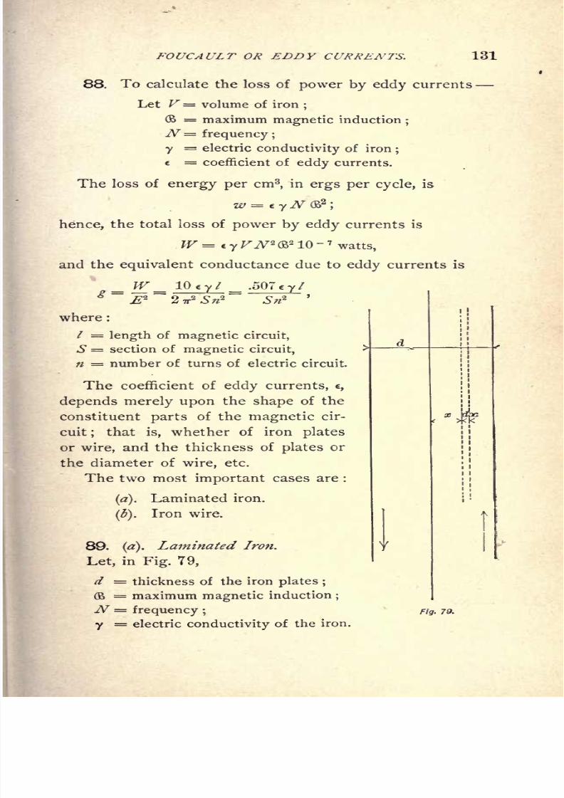
88. To calculate the loss of power by eddy currents
Let V= volume of iron;
(B = maximum magnetic induction;
N= frequency;
y= electric conductivity of iron
;
= coefficient of eddy currents.
The loss of energy per cm3
,in ergs per cycle, is
hence, the total loss of power by eddy currents is
W = e y VN* (B2 10
- 7
watts,
and the equivalent conductance due to eddy currents is
8/2/2019 Charles Steinmetz Theorycalculatio00steiiala
http://slidepdf.com/reader/full/charles-steinmetz-theorycalculatio00steiiala 158/557
132 ALTERNATING-CURRENT PHENOMENA.
Then, if x is the distance of a zone, d x, from the center
of the sheet, the conductance of a zone of thickness, */x,
and of one cm length and width is y^x ;and the magnetic
flux cut by this zone is (Bx. Hence, the E.M.F. induced in
this zone is
8 E = V2 TrN($> x, in C.G.S. units.
This E.M.F. produces the current :
///=S J y</x = V2 TrN<$> y x dx, in C.G.S. units,
provided the thickness of the plate is negligible as compared
with the length, in order that the current may be assumed
as flowing parallel to the sheet, and in opposite directions
on opposite sides of the sheet.
The power consumed by the induced current in this
zone, dx, is
dP = EdI= 2 7T2^2
(B2
y xVx, in C.G.S. units or ergs per second,
and, consequently, the total power consumed in one cm2 of
the sheet of thickness, d, is
= C+ *
dP = 27rW 2(B
2
y Cin C.G.S. units;
the power consumed per cm3 of iron is, therefore,
.
/ = =- '-
,m C.G.S. units or erg-seconds,
and the energy consumed per cycle and per cm3 of iron is
N 6
The coefficient of eddy currents for laminated iron is,
therefore,
c = ^- = 1.645 d\
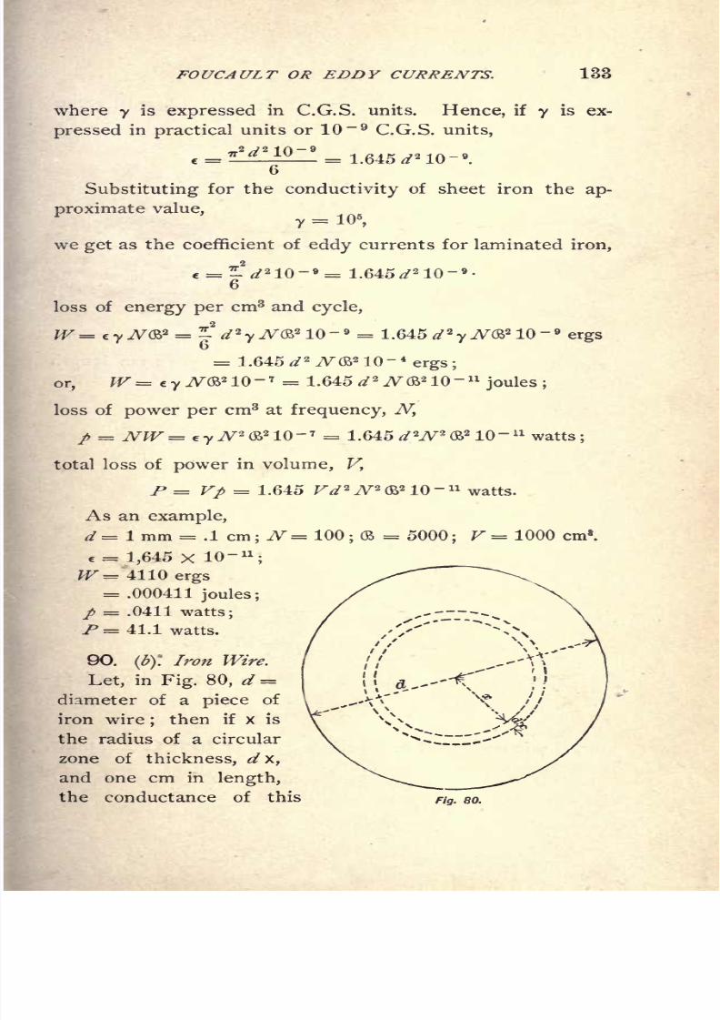
8/2/2019 Charles Steinmetz Theorycalculatio00steiiala
http://slidepdf.com/reader/full/charles-steinmetz-theorycalculatio00steiiala 159/557

8/2/2019 Charles Steinmetz Theorycalculatio00steiiala
http://slidepdf.com/reader/full/charles-steinmetz-theorycalculatio00steiiala 160/557
134 ALTERNATING-CURRENT PHENOMENA.
zone is, y^/x/2 TT x, and the magnetic flux inclosed by the
zone is (B x 2 *.
Hence, the E.M.F. induced in this zone is :
8 = V2 7r2 ^(B x
2
,in C.G.S. units,
and the current produced thereby is,
,in C.G.S. units.
The power consumed in this zone is, therefore,
dP= EdI= 7T8
y N'2(B
2 x3d x, in C.G.S. units
consequently, the total power consumed in one cm length
of wireis
8P =f~dW = 7T
3
y N'1 2 f
*
xa dx
=^-y^
2 &V 4
,in C.G.S. units.
Since the volume of one cm length of wire is
/ ,*?,
-
'Ithe power consumed in one cm3 of iron is
x P 2
P =-^-
=^ y^2 (BV 2
,in C.G.S. units or erg-seconds,
and the energy consumed per cycle and cm3 of iron is
ergs.
Therefore, the coefficient of eddy currents for iron wire is
c =^^
2 = .617 </2
;
or, if y is expressed in practical units, or 10~ 9 C.G.S. units,
c = -^10
8/2/2019 Charles Steinmetz Theorycalculatio00steiiala
http://slidepdf.com/reader/full/charles-steinmetz-theorycalculatio00steiiala 161/557
FOUCAULT OR EDDY CURRENTS. 135
Substituting^=
^we get as the coefficient of eddy currents for iron wire,
e= ^ 2 10~ 9 = .617 </2 10- 9
.
16
The loss of energy per cm3 of iron, and per cycle
becomes
= .617 d*N? 10~ 4
ergs,
loss of power per cm3
,at frequency, N,
p = Nh = ey^2(B
2 10- 7 = .617 d 2 N*<$? 10-" watts;
total loss of power in volume, V,
P= Vp = .617 FVJV'&'IO- 11watts.
As an example,
d = 1 mm, = .1 cm;N= 100
;
2 = 5,000 ;V= 1000 cm8
.
e = .617 X 10- 11
,
W= 1540 ergs= .000154 joules,
p = .0154 watts,
P = 15.4 watts,
hence very much less than in sheet iron of equal thickness.
91. Comparison of sheet iron and iron wire.
If
//!= thickness of lamination of sheet iron, and
dz= diameter of iron wire,
the eddy-coefficient of sheet iron being
T* j 2 10-9*T?
and the eddy coefficient of iron wire

8/2/2019 Charles Steinmetz Theorycalculatio00steiiala
http://slidepdf.com/reader/full/charles-steinmetz-theorycalculatio00steiiala 162/557
136 AL TERNA TING-CURRENT PHENOMENA.
the loss of power is equal in both other things being
equal if ex = e
2 ;that is, if,
# =!</!,
or 4 = 1.63 ^.o
It follows that the diameter of iron wire can be 1.63
times, or, roughly, 1| as large as the thickness of laminated
iron, to give the same loss of energy through eddy currents,
as shown in Fig. 81.
Fig. 81.
92. Demagnetizing, or screening effect of eddy currents.
The formulas derived for the coefficient of eddy cur-
rents in laminated iron and in iron wire, hold only when
the eddy currents are small enough to neglect their mag-
netizing force. Otherwise the phenomenon becomes more
complicated; the magnetic flux in the interior of the lam-
ina, or the wire, is not in phase with the flux at the sur-
face, but lags behind it. The magnetic flux at the surface
is due to the impressed M.M.F., while the flux in the inte-
rior is due to the resultant of the impressed M.M.F. and to
the M.M.F. of eddy currents;since the eddy currents lag
90 behind the flux producing them, their resultant with
theimpressed M.M.F.,
and therefore themagnetism
in the
8/2/2019 Charles Steinmetz Theorycalculatio00steiiala
http://slidepdf.com/reader/full/charles-steinmetz-theorycalculatio00steiiala 163/557
FOUCAULT OR EDDY CUKREN7*S. 137
interior, is made lagging. Thus, progressing from the sur-
face towards the interior, the magnetic flux gradually lags
more and more in phase, and at the same time decreases
in intensity. While the complete analytical solution of this
phenomenon is beyond the scope of this book, a determina-
tion of the magnitude of this demagnetization, or screening
effect, sufficient to determine whether it is negligible, or
whether the subdivision of the iron has to be increased
to make it negligible, can be made by calculating the maxi-
mum magnetizing effect, which cannot be exceeded by the
eddys.
Assuming the magnetic density as uniform over the
whole cross-section, and therefore all the eddy currents in
phase with each other, their total M.M.F. represents the
maximum possible value, since by the phase difference and
the lesser magnetic density in the center the resultant
M.M.F. is reduced.
In laminated iron of thickness d, the current in a zone
of thickness, dx at distance x from center of sheet, is :
dl= -rrN&jxdx units (C.G.S.)
= V2 TT
N&jxdx10
- 8
amperes;
hence the total current in sheet is
/=
amperes.
Hence, the maximum possible demagnetizing ampere-turns
acting upon the center of the lamina, are
A/9 - 8 = .555 N&jd* 10- 8
8
= .555 ./V(B</2 10~ 3
ampere-turns per cm
Example : d = .1 cm, N= 100, (B = 5,000,
or / = 2.775 ampere-turns per cm.
8/2/2019 Charles Steinmetz Theorycalculatio00steiiala
http://slidepdf.com/reader/full/charles-steinmetz-theorycalculatio00steiiala 164/557
138 ALTERNATING-CURRENT PHENOMENA.
93. In iron wire of diameter d, the current in a tubular
zone of dx thickness and x radius is
dl= TT JV&j'x dxlO-* amperes;
hence, the total current is
I = f$4I~?2. vN&j 10- f* xdxJo " Jo
A/9 ~ *
amperes.16
Hence, the maximum possible demagnetizing ampere-turns,
acting upon the center of the wire, are
10-
16
=.2775 N(S> d* 10
- 8
ampere-turns percm.
For example, if d= .1 cm, N = 100, = 5,000, then
/= 1,338 ampere-turns per cm; that is, half as much as in
a lamina of the thickness d.
94. Besides the eddy, or Foucault, currents proper, which
flow as parasitic circuits in the interior of the iron lamina
or wire, under certain circumstances eddy currents also
flow in larger orbits from lamina to lamina through the
whole magnetic structure. Obviously a calculation of these
eddy currents is possible only in a particular structure.
They are mostly surface currents, due to short circuits
existing between the laminae at the surface of the magnetic
structure.
Furthermore, eddy currents are induced outside of the
magnetic iron circuit proper, by the magnetic stray field
cutting electric conductors in the neighborhood, especially
when drawn towards them by iron masses behind, in elec-
tric conductors passing through the iron of an alternating
field, etc. All these phenomena can be calculated only in
particular cases, and are of less interest, since they can
and should be avoided.

8/2/2019 Charles Steinmetz Theorycalculatio00steiiala
http://slidepdf.com/reader/full/charles-steinmetz-theorycalculatio00steiiala 165/557
FOUCAULT OR EDDY CURRENTS. 139
Eddy Currents in Conductor, and Unequal Current
Distribution.
95. If the electric conductor has a considerable size, the
alternating magnetic field, in cutting the conductor, mayset up differences of potential between the different parts
thereof, thus giving rise to local or eddy currents in the
copper. This phenomenon can obviously be studied only
with reference to a particular case, where the shape of the
conductor and the distribution of the magnetic field are
known.
Only in the case where the magnetic field is produced
by the current flowing in the conductor can a general solu-
tion be given. The alternating current in the conductor
produces a magnetic field, not only outside of the conductor,
but inside of it also;and the lines of magnetic force which
close themselves inside of the conductor induce E.M.Fs.
in their interior only. Thus the counter E.M.F. of self-
inductance is largest at the axis of the conductor, and least
at its surface; consequently, the current density at the
surface will be larger than at the axis, or, in extreme cases,
the current may not penetrate at all to the center, or areversed current flow there. Hence it follows that only the
exterior part of the conductor may be used for the conduc-
tion of the current, thereby causing an increase of the
ohmic resistance due to unequal current distribution.
The general solution of this problem for round conduc-
tors leads to complicated equations, and can be found else-
where.
In practice, this phenomenon is observed only with very
high frequency currents, as lightning discharges ;in power
distribution circuits it has to be avoided by either keeping
the frequency sufficiently low, or having a shape of con-
ductor such that unequal current distribution does not
take place, as by using a tubular or a flat conductor, or
several conductors in parallel.

8/2/2019 Charles Steinmetz Theorycalculatio00steiiala
http://slidepdf.com/reader/full/charles-steinmetz-theorycalculatio00steiiala 166/557
140 ALTERNATING-CURRENT PHENOMENA.
96. It will, therefore, be sufficient to determine the
largest size of round conductor, or the highest frequency,
where this phenomenon is still negligible.
In the interior of the conductor, the current density
is not only less than at the surface, but the current lags
behind the current at the surface, due to the increased
effect of self-inductance. This lag of the current causes the
magnetic fluxes in the conductor to be out of phase with
each other, making their resultant less than their sum, while
the lesser current density in the center reduces the total
flux inside of the conductor. Thus, by assuming, as a basis
for calculation, a uniform current density and no difference
of phase between the currents in the different layers of the
conductor, the unequal distribution is found larger than it
is in
reality.
Hence this
assumption brings
us on the safe
side, and at the same time simplifies the calculation greatly.
Let Fig. 82 represent a cross-section of a conductor of
radius R, and a uniform current density,
where / = total current in conductor.
Fig. 82.
The magnetic reluctance of a tubular zone of unit length
and thickness dxtof radius x, is

8/2/2019 Charles Steinmetz Theorycalculatio00steiiala
http://slidepdf.com/reader/full/charles-steinmetz-theorycalculatio00steiiala 167/557
FOUCAULT OR EDDY CURRENTS. 141
The current inclosed by this zone is Ix = zW, and there
fore, the M.M.F. acting upon this zone is
$x= 47r Ix / 10 = 4 **/ 10,
and the magnetic flux in this zone is
d$> = $x I G(x = 2 Trixdx / 10.
Hence, the total magnetic flux inside the conductor is
,27T . CR . TTiR* I
From this we get, as the excess of counter E.M.F. at the
axis of the conductor over that at the surface
&E = V27r^0> 10~ 8 = V27r7W10
- 9
, per unit length,
and the reactivity, or specific reactance at the center of the
conductor, becomes k = &E / i = V2 i^NR* 10~ 9
.
Let p=
resistivity,or specific resistance, of the material of
the conductor.
We have then, k/p = V^TrW^lO- 9
/?;
and p/ VFT7,
the ratio of current densities at center and at periphery.
Forexample,
if, in
copper, p
= 1.7xlO 6,and the
percentage decrease of current density at center shall not
exceed 5 per cent, that is
P -H VF+72 = .95 - 1,
we have, = .51xlO-;
hence .51 x 10- 6 = V^TrW^lO- 9
or N2? = 36.6;
hence, when N= 125 100 60 25= .541 .605 .781 1.21 cm.
D = 1R= 1.08 1.21 1.56 2.42cm.
Hence, even at a frequency of 125 cycles, the effect of
unequal current distribution is still negligible at one cm
diameter of the conductor. Conductors of this size are,
however, excluded from use at this frequency by the exter-
nal self-induction, which is several times larger than the.

8/2/2019 Charles Steinmetz Theorycalculatio00steiiala
http://slidepdf.com/reader/full/charles-steinmetz-theorycalculatio00steiiala 168/557
142 ALTERNATING-CURRENT PHENOMENA.
resistance. We thus see that unequal current distribution
is usually negligible in practice. The above calculation was
made under the assumption that the conductor consists of
unmagnetic material. If this is not the case, but the con-
ductor of iron of permeability p.,then
;d$ = pffx / (&x and
thus ultimately ;k = V2 wW/^10
~" and;k / P
= V2 **
NpR* 10 '// Thus, for instance, for iron wire at
/>= 10xlO- 6
, ft= 500 it is, permitting 5% difference
between center and outside of wire; k = 3.2 X 10 ~ 6 and
NR* = .46,
hence when, N= 125 100 60 25
X = .061 .068 .088 .136 cm.
thus the effect is noticeable even with relatively small iron
wire.
Mutual Inductance.
97. When an alternating magnetic field of force includes
a secondary electric conductor, it induces therein an E.M.F.
which produces a current, and thereby consumes energy if
the circuit of the secondary conductor is closed.
A particular case of such induced secondary currents
are the eddy or Foucault currents previously discussed.
Another important case is the induction of secondary
E.M.Fs. in neighboring circuits;that is, the interference of
circuits running parallel with each other.
In general, it is preferable to consider this phenomenon
of mutual inductance as not merely producing an energy
component and a wattless component of E.M.F. in the
primary conductor, but to consider explicitly both the sec-
ondary and the primary circuit, as will be done in the
chapter on the alternating-current transformer.
Only in cases where the energy transferred into the
secondary circuit constitutes a small part of the total pri-
mary energy, as in the discussion of the disturbance caused
by one circuit upon a parallel circuit, may the effect on the
primary circuit be considered analogously as in the chapter
on eddy currents, by the introduction of an energy com-

8/2/2019 Charles Steinmetz Theorycalculatio00steiiala
http://slidepdf.com/reader/full/charles-steinmetz-theorycalculatio00steiiala 169/557
FOUCAULT OR EDDY CURRENTS. 143
ponent, representing the loss of power, and a wattless
component, representing the decrease of self-inductance.
Let
x = 2 TTNL = reactance of main circuit;that is, L =
total number of interlinkages with the main conductor, of
the lines of magnetic force produced by unit current in
that conductor;
.#!= 2-jrNL
1= reactance of secondary circuit
;that is,
Ll = total number of interlinkages with the secondary
conductor, of the lines of magnetic force produced by unit
current in that conductor;
xm = 2 TTNLm = mutual inductance of circuits;that is,
Lm = total number of interlinkages with the secondary
conductor, of the lines of magnetic force produced by unit
current in the mainconductor,
or total number of inter-
linkages with the main conductor of the lines of magnetic
force produced by unit current in the secondary conductor.
Obviously : xm* < xx^*
* As coefficient of self-inductance L, L^, the total flux surrounding the conductor
is here meant. Usually in the discussion of inductive apparatus, especially of trans-
formers, that part of the magnetic flux is derroted self-inductance of the one circuit
which surrounds this circuit, but not the other circuit;that is, which passes between
both circuits. Hence, the total self-inductance, L, is in this ease equal to the sum of
the self-inductance, Z,j, and the mutual inductance, Lm .
The object of this distinction is to separate the wattless part, Z1?of the
total self-inductance, L, from that part,Lm ,
which represents the transfer of
E.M.F. into the secondary circuit, since the action of these two components is
essentially different.
Thus, in alternating-current transformers it is customary and will be
done later in this book to denote as the self-inductance, Z, of each circuit
only that part of the magnetic flux produced by the circuit which passes
between both circuits, and thus acts in"choking
"only, but not in transform-
ing; while the flux surrounding both circuits is called mutual inductance, or
useful magnetic flux.
With' this denotation, in transformers the mutual inductance, Lm ,is usu-
ally very much greater than the self-inductances, //, and Z/, while, if the
self-inductances, Z and Zj , represent the total flux, their product is larger
than the square of the mutual inductance, Lm ;or

8/2/2019 Charles Steinmetz Theorycalculatio00steiiala
http://slidepdf.com/reader/full/charles-steinmetz-theorycalculatio00steiiala 170/557
144 ALTERNATING CURRENT PHENOMENA.
Let rx= resistance of secondary circuit. Then the im-
pedance of secondary circuit is
^i = rv /*! ,
zl= V/v + xi
2
;
E.M.F. induced in the secondary circuit,=jxm f,
where / = primary current. Hence, the secondary current is
and the E.M.F. induced in the primary circuit by the secon-
dary current, 7lis
or, expanded,Y zr j~. 2xm^ JXm
2 _i_
r2
r2 i JT
T^ ^i "l " * 2
Hence, the E.M.F. consumed thereby
effective resistance of mutual inductance;
^ = effective reactance of mutual inductance.
The susceptance of mutual inductance is negative, or of
opposite sign from the reactance of self-inductance. Or,
Mutual inductance consumes energy and decreases theself-
inductance.
Dielectric and Electrostatic Phenomena.
98. While magnetic hysteresis and eddy currents can
be considered as the energy component of inductance, con-
densance has an energy component also, namely, dielectric
hysteresis. In an alternating magnetic field, energy is con-
sumed in hysteresis due to molecular friction, and similarly,
energy is also consumed in an alternating electrostatic field
in the dielectric medium, in what is called electrostatic or
dielectric hysteresis.
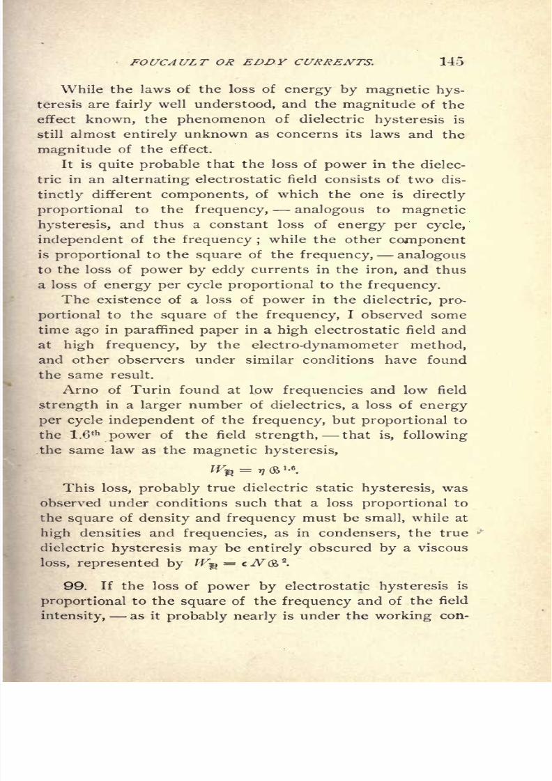
8/2/2019 Charles Steinmetz Theorycalculatio00steiiala
http://slidepdf.com/reader/full/charles-steinmetz-theorycalculatio00steiiala 171/557
FOUCAULT OR EDDY CURRENTS. 145
While the laws of the loss of energy by magnetic hys-
teresis are fairly well understood, and the magnitude of the
effect known, the phenomenon of dielectric hysteresis is
still almost entirely unknown as concerns its laws and the
magnitude of the effect.
It is quite probable that the loss of power in the dielec-
tric in an alternating electrostatic field consists of two dis-
tinctlydifferent
components,of which the one is
directly
proportional to the frequency, analogous to magnetic
hysteresis, and thus a constant loss of energy per cycle,
independent of the frequency ;while the other component
is proportional to the square of the frequency, analogous
to the loss of power by eddy currents in the iron, and thus
a loss of energy per cycle proportional to the frequency.
The existence of a loss of power in the dielectric, pro-
portional to the square of the frequency, I observed some
time ago in paraffined paper in a high electrostatic field and
at high frequency, by the electro-dynamometer method,
and other observers under similar conditions have found
the same result.
Arno of Turin found at low frequencies and low field
strength in a larger number of dielectrics, a loss of energy
per cycle independent of the frequency, but proportional to
the 1.6th
power of the field strength, that is, following
the same law as the magnetic hysteresis,
^ =^(B'-
6.
This loss, probably true dielectric static hysteresis, was
observed under conditions such that a loss proportional to
the square of density and frequency must be small, while at
high densities and frequencies, as in condensers, the true
dielectric hysteresis may be entirely obscured by a viscous
loss, represented by W^ = e7V(B2
.
99. If the loss of power by electrostatic hysteresis is
proportional to the square of the frequency and of the field
as it is under the con-
8/2/2019 Charles Steinmetz Theorycalculatio00steiiala
http://slidepdf.com/reader/full/charles-steinmetz-theorycalculatio00steiiala 172/557
146 ALTERNA TING-CURRENT PHENOMENA.
ditions of
alternating-currentcondensers, then it is
pro-portional to the square of the E.M.F., that is, the effective
conductance, g, due to dielectric hysteresis is a constant;
and, since the condenser susceptance, b= b', is a constant
also, unlike the magnetic inductance, the ratio of con-
ductance and susceptance, that is, the angle of difference
of phase due to dielectric hysteresis, is a constant. This I
found proved by experiment. This would mean that the
dielectric hysteretic admittance of a condenser,
Y=g+jb=g-jb',
where : g = hysteretic conductance, b' = hysteretic suscep-
tance;and the dielectric hysteretic impedance of a con-
denser, . . .
Z = r jx r +jxc ,
where : r = hysteretic resistance, xc hysteretic condens-
ance;and the angle of dielectric hysteretic lag, tan a = b' /g
= xc / r, are constants of the circuit, independent of E.M.F.
and frequency. The E.M.F. is obviously inversely propor-
tional to the frequency.
The true static dielectric hysteresis, observed by Arno
as proportional to the 1.6th
power of the density, will enter
the admittance and the impedance as a term variable and
dependent upon E.M.F. and frequency, in the same manner
as discussed in the chapter on magnetic hysteresis.
To the magnetic hysteresis corresponds, in the electro-
static field, the static component of dielectric hysteresis,
following, probably, the same law of 1.6th
power.
To the eddycurrents in the iron
corresponds,in
theelectrostatic field, the viscous component of dielectric hys-
teresis, following the square law.
As a rule however, these hysteresis losses in the alter-
nating electrostatic field of a condenser are very much
smaller than the losses in an alternating magnetic field, so
that while the latter exert a very marked effect on the de-
sign of apparatus, representing frequently the largest of all

8/2/2019 Charles Steinmetz Theorycalculatio00steiiala
http://slidepdf.com/reader/full/charles-steinmetz-theorycalculatio00steiiala 173/557
FOUCAULT OR EDDY CURRENTS. 147
To the phenomenon of mutual inductance corresponds,
in the electrostatic field, the electrostatic induction, or in-
fluence.
100. The alternating electrostatic field of force of an
electric circuit induces, in conductors within the field of
force, electrostatic charges by what is called electrostatic
influence. These charges are proportional to the field
strength ;that is, to the E.M.F. in the main circuit.
If a flow of current is produced by the induced charges,
energy is consumed proportional to the square of the charge ;
that is, to the square of the E.M.F.
These induced charges, reacting upon the main conduc-
tor, influence therein charges of equal but opposite phase,
and hence laggingbehind the
main E.M.F. bythe
angleof lag between induced charge and inducing field. They
require the expenditure of a charging current in the main
conductor in quadrature with the induced charge thereon;
that is, nearly in quadrature with the E.M.F., and hence
consisting of an energy component in phase with the
E.M.F. representing the power consumed by electrostatic
influence and a wattless component, which increases the
capacity of the conductor, or, in other words, reduces its
capacity reactance, or condensance.
Thus, the electrostatic influence introduces an effective
conductance, g, and an effective susceptance, b, of the
same sign with condenser susceptance, into the equations
of the electric circuit.
While theoretically g and b should be constants of the
circuit, frequently they are very far from such, due to
disruptive phenomena beginning to appear at high electro-
static stresses.
Even the capacity condensance changes at very high
potentials ; escape of electricity into the air and over the
surfaces of the
supporting
insulators
by
brush discharge or
electrostatic glow takes place. As far as this electrostatic

8/2/2019 Charles Steinmetz Theorycalculatio00steiiala
http://slidepdf.com/reader/full/charles-steinmetz-theorycalculatio00steiiala 174/557
148 ALTERNATING-CURRENT PHENOMENA
corona reaches, the space is in electric connection with the
conductor, and thus the capacity of the circuit is deter-
mined, not by the surface of the metallic conductor, but
by the exterior surface of the electrostatic glow surround-
ing the conductor. This means that with increasing po-
tential, the capacity increases as soon as the electrostatic
corona appears ; hence, the condensance decreases, and at
the same time an energy component appears, representingthe loss of power in the corona.
This phenomenon thus shows some analogy with the de-
crease of magnetic inductance due to saturation.
At moderate potentials, the condensance due to capacity
can be considered as a constant, consisting of a wattless
component, the condensance proper, and an energy com-
ponent, the dielectric hysteresis.
The condensance of a polarization cell, however, begins
to decrease at very low potentials, as soon as the counter
E.M.F. of chemical dissociation is approached.
The condensance of a synchronizing alternator is of
the nature of a variable quantity ;that is, the effective
reactance changes gradually, according to the relation of
impressed and of counter E.M.F., from inductance over
zero to condensance.
Besides the phenomena discussed in the foregoing as
terms of the energy components and the wattless compo-
nents of current and of E.M.F., the electric leakage is
to be considered as a further energy component ;that is,
the direct
escape
of current from conductor to return con-
ductor through the surrounding medium, due to imperfect
insulating qualities. This leakage current represents an
effective conductance, g, theoretically independent of the
E.M.F., but in reality frequently increasing greatly with the
E.M.F., owing to the decrease of the insulating strength of
the medium upon approaching the limits of its disruptive
strength.

8/2/2019 Charles Steinmetz Theorycalculatio00steiiala
http://slidepdf.com/reader/full/charles-steinmetz-theorycalculatio00steiiala 175/557
FOUCAULT OR EDDY CURRENTS. 149
101. In the foregoing, the phenomena causing loss of
energy in an alternating-current circuit have been dis-
cussed;and it has been shown that the mutual relation
between current and E.M.F. can be expressed by two of
the four constants :
Energy component of E.M.F., in phase with current, and =current X effective resistance, or r
;
wattless component of E.M.F., in quadrature with current, and =current 'X effective reactance, or x
energy component of current, in phase with E.M.F., and =E.M.F. X effective conductance, or g ;
wattless component of current, in quadrature with E.M.F., and =E.M.F. X effective susceptance, or b.
In many cases the exact calculation of the quantities,
r, x, g, b, is not possible in the present state of the art.
In general, r, x, g, b, are not constants of the circuit, but
depend besides upon the frequency more or less upon
E.M.F., current, etc. Thus, in each particular case it be-
comes necessary to discuss the variation of r, x, g, b, or to
determine whether, and through what range, they can be
assumed as constant.
In what follows, the quantities r, x, g, b, will always be
considered as the coefficients of the energy and wattless
components of current and E.M.F., that is, as the effec-
tive quantities, so that the results are directly applicable
to the general electric circuit containing iron and dielectric
losses.
Introducing now,in
ChaptersVII. to
IX.,instead of
" ohmic resistance," the term "effective resistance," etc.,
as discussed in the preceding chapter, the results apply
also within the range discussed in the preceding chapter
to circuits containing iron and other materials producing
energy losses outside of the electric conductor.

8/2/2019 Charles Steinmetz Theorycalculatio00steiiala
http://slidepdf.com/reader/full/charles-steinmetz-theorycalculatio00steiiala 176/557
150 ALTERNATING-CURRENT PHENOMENA.
CHAPTER XII.
POWER, AND DOUBLE FREQUENCY QUANTITIESIN GENERAL.
102. Graphically alternating currents and E.M.F's
are represented by vectors, of which the length represents
the intensity, the direction the phase of the alternating
wave. The vectors generally issue from the center of
co-ordinates.
In the topographical method, however, which is more
convenient for complex networks, as interlinked polyphase
circuits, the alternating wave is represented by the straight
line between two points, these points representing the abso-
lute values of potential (with regard to any reference point
chosen as co-ordinate center) and their connection the dif-
ference of potential in phase and intensity.
Algebraically these vectors are represented by complex
quantities. The impedance, admittance, etc., of the circuit
is a complex quantity also, in symbolic denotation.
Thus current, E.M.F., impedance, and admittance are
related by multiplication and division of complex quantities
similar as current, E.M.F., resistance, and conductance are
related by Ohms law in direct current circuits.
In direct current circuits, power is the product of cur-
rent into E.M.F. In alternating current circuits, if
The product,
P = EI= l - +j (W
8/2/2019 Charles Steinmetz Theorycalculatio00steiiala
http://slidepdf.com/reader/full/charles-steinmetz-theorycalculatio00steiiala 177/557
POWER, AND DOUBLE FREQUENCY QUANTITIES. 151
is not the power; that is, multiplication and division, which
are correct in the inter-relation of current, E.M.F., impe-
dance, do not give a correct result in the inter-relation of
E.M.F., current, power. The reason is, that El are vec-
tors of the same frequency, and Z a constant numerical
factor which thus does not change the frequency.
The power P, however, is of double frequency compared
with E and /, that is, makes a
complete
wave for
everyhalf wave of E or 7, and thus cannot be represented by a
vector in the same diagram with E and /.
P = E I is a quantity of the same frequency with E
and /, and thus cannot represent the power.
\
103. Since the power is a quantity of double frequency
of E and /, and thus a phase angle w in E and / corre-
sponds to a phase angle 2 w in the power, it is of interest to
investigate the product E I formed by doubling the phase
angle.
Algebraically it is,
P=EI= (* +>") (V1
+/zn)=
Since j*= -
1, that is 180 rotation for E and /, for the
double frequency vector, P,j* = + 1, or 360 rotation, and
j x 1 =j1 x>= -j
That is, multiplication with / reverses the sign, since it
denotes a rotation by 180 for the power, corresponding to
a rotation of 90 for E and /.
Hence, substituting these values, we have,
p = [El]= (W
1 + ^V11
) +/ (W1 - A'u
)
The symbol [E /]here denotes the transfer from the
of E and / to the double of P.
8/2/2019 Charles Steinmetz Theorycalculatio00steiiala
http://slidepdf.com/reader/full/charles-steinmetz-theorycalculatio00steiiala 178/557
152 ALTERNA TING-CURRENT PHENOMEMA.
The product, P =\E /] consists of two components ;
the real component,
JP1 = [EIJ = (W1 + e"in)
and the imaginary component,
JPJ =j
The component,
P1
is the power of the circuit,= E I cos (E /)
The component,
PJ =
is what may be called the " wattless power," or the power-
less or quadrature volt-amperes of the circuit,= E /sin
(El}.
The real component will be distinguished by the index
1, the imaginary or wattless component by the index/.
By introducing this symbolism, the power of an alternat-
ing circuit can be represented in the same way as in the
direct current circuit, as the symbolic product of current
and E.M.F.
Just as the symbolic expression of current and E.M.F.
as complex quantity does not only give the mere intensity,
but also the phase,=
jfc ==
Ptan <f>
= -j
so the double frequency vector product P =[E /] denotes
more than the mere power, by giving with its two compo-
nents P1 = [E I]1 and PJ = [E /]>, the true energy volt-
amperes, and the wattless volt-amperes.
If
E =

8/2/2019 Charles Steinmetz Theorycalculatio00steiiala
http://slidepdf.com/reader/full/charles-steinmetz-theorycalculatio00steiiala 179/557
POWER, AND DOUBLE FREQUENCY QUANTITIES. 153
then
and
P1 =
or
2 2 22 22 22 22+PJ =<* ,1 + *" /
where ^ = total volt amperes of circuit. That is,
The true
power P
1 and the wattless
powerP$ are the two
rectangular components of the total apparent power Q of the
circuit.
Consequently,
In symbolic representation as doublefreqi'ency vector pro-
ducts, powers can be combined and resolved by the parallelo-
gram of vectors just as currents and E.M.F's in graphical
or symbolic representation.
The graphical methods of treatment of alternating cur-
rent phenomena are here extended to include double fre-
quency quantities as power, torque, etc.
P1
=p = cos w = power factor.
PJ =q= sin w = inductance factor
of the circuit, and the general expression of power is,
= Q (cos co -\-j sino>)
104. The introduction of the double frequency vector
product P = \E I~\ brings us outside of the limits of alge-
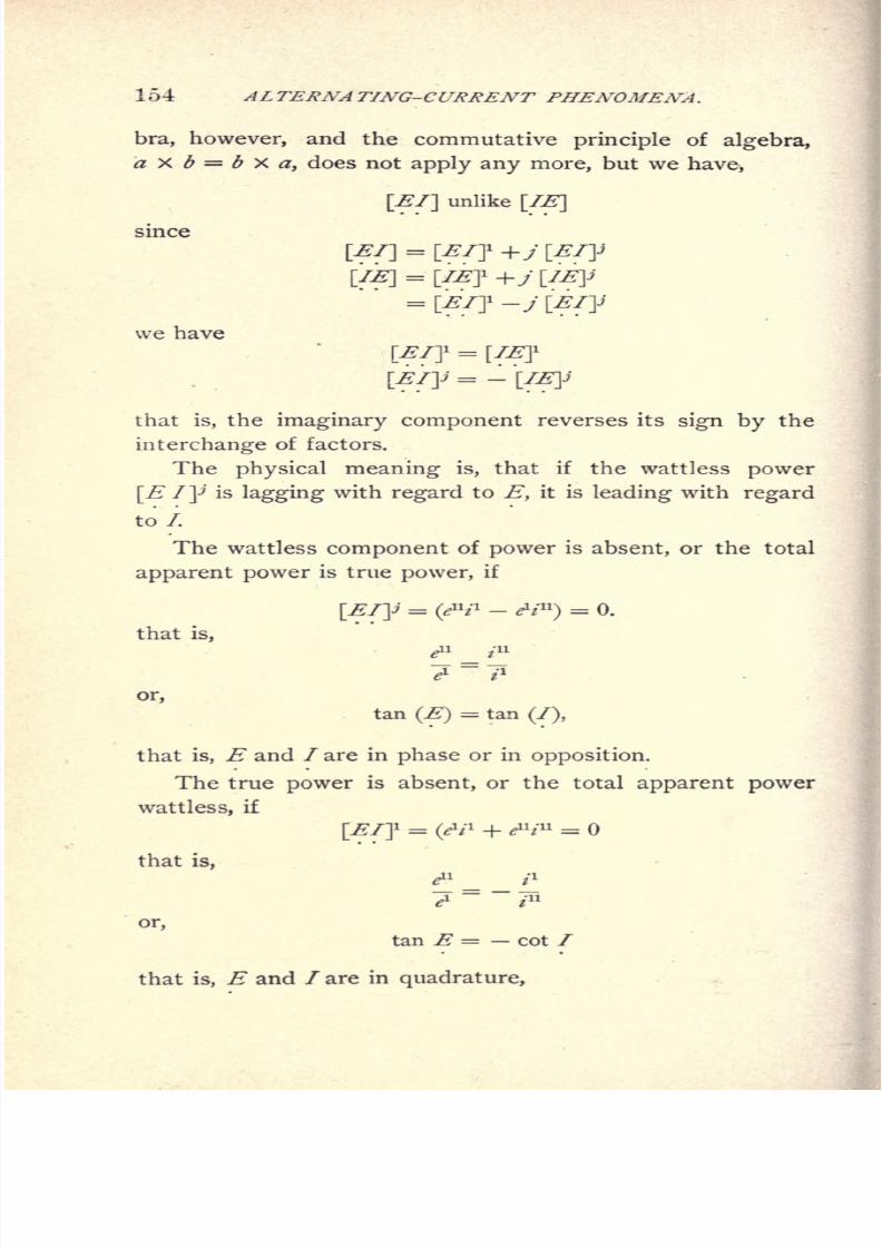
8/2/2019 Charles Steinmetz Theorycalculatio00steiiala
http://slidepdf.com/reader/full/charles-steinmetz-theorycalculatio00steiiala 180/557
154 ALTERNATING-CURRENT PHENOMENA.
bra, however, and the commutative principle of algebra,
a X b = b X a, does not apply any more, but we have,
[El] unlike [IE]
since
we have
[EIJ = [IEJ
[EI]J=-[IE]J
that is, the imaginary component reverses its sign by the
interchange of factors.
The physical meaning is, that if the wattless power
[E 7p is lagging with regard to E, it is leading with regard
to/.
The wattless component of power is absent, or the total
apparent power is true power, if
[EI]J= (W1 - A'11
)= 0.
thatis,
or,
tan (E)= tan
(/),
that is, E and / are in phase or in opposition.
The true power is absent, or the total apparent power
wattless, if
[El]1 = (W
1 + M* =
that is,
*" _ i1
7~~/
or,
tan E = cot I
that is, E and / are in quadrature,
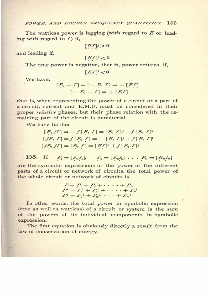
8/2/2019 Charles Steinmetz Theorycalculatio00steiiala
http://slidepdf.com/reader/full/charles-steinmetz-theorycalculatio00steiiala 181/557
POWER, AND DOUBLE FREQUENCY QUANTITIES. 155
The wattless power is lagging (with regard to E or lead-
ing with regard to /) if,
and leading if,
The true power is negative, that is, power returns, if,
We have,
[,-
7]= [- E, 7]
= -
that is, when representing the power of a circuit or a part of
a circuit, current and E.M.F. must be considered in their
proper relative phases, but their phase relation with the re-
maining part of the circuit is immaterial.
We have further
\EJT\ = -j [, 7]=
[E, iy -j \E, 7]1
\JE, 7] =j [E, 7]= -
[E, Jy +j [E, 7]1
\jEjr\ = [, 7]= [E7? +j [E, jy
105. If 7- =[^/J,
7>2 = [E2/2]
. . . Pn = [Enln}
are the symbolic expressions of the power of the different
parts of a circuit or network of circuits, the total power of
the whole circuit or network of circuits is
7^' = TV + T'ijJ.. + TV
In other words, the total power in symbolic expression
(true as well as wattless) of a circuit or system is the sum
of the powers of its individual components in symbolic
expression.
The first equation is obviously directly a result from thelaw of conservation of

8/2/2019 Charles Steinmetz Theorycalculatio00steiiala
http://slidepdf.com/reader/full/charles-steinmetz-theorycalculatio00steiiala 182/557
156 ALTERNATING-CURRENT PHENOMENA.
One result derived herefrom is for instance :
If in a generator supplying power to a system the cur-
rent is out of phase with the E.M.F. so as to give the watt-
less power Pi, the current can be brought into phase with
the generator E.M.F., or the load on the generator made
non-inductive by inserting anywhere in the circuit an appa-
ratus producing the wattless power F$\ that is, compen-
sation for wattless currents in a system takes place regardless
of the location of the compensating device.
Obviously between the compensating device and the
source of wattless currents to be compensated for, wattless
currents will flow, and for this reason it may be advisable
to bring the compensator as near as possible to the circuit
to be compensated.
106. Like power, torque in alternating apparatus is a
double frequency vector product also, of magnetism and
M.M.F. or current, and thus can be treated in the same
way.
In an induction motor, for instance, the torque is the
product of the magnetic flux in one direction into the com-
ponentof
secondaryinduced current in
phasewith the
magnetic flux in time, but in quadrature position therewith
in space, times the number of turns of this current, or since
the induced E.M.F. is in quadrature and proportional to
the magnetic flux and the number of turns, the torque
of the induction motor is the product of the induced E.M.F.
into the component of secondary current in quadrature
therewith in time and space, or the product of the inducedcurrent into the component of induced E.M.F. in quadra-
ture therewith in time and space.
Thus if
E1 = +jea-
induced E.M.F. in one direction in
space.
72= z
1
+j z11 =
secondary current in the quadrature di-
rection in space,
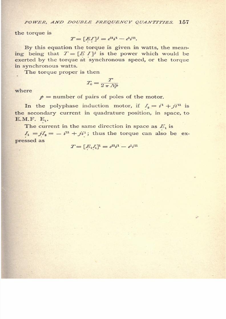
8/2/2019 Charles Steinmetz Theorycalculatio00steiiala
http://slidepdf.com/reader/full/charles-steinmetz-theorycalculatio00steiiala 183/557
POWER, AND DOUBLE FREQUENCY QUANTITIES. 157
the torque is
By this equation the torque is given in watts, the mean-
ing being that T = \E /]>'is the power which would be
exerted by the torque at synchronous speed, or the torque
in synchronous watts.
The torque proper is then
where
/ = number of pairs of poles of the motor.
In the polyphase induction motor, if 72= i
l
+/zu
is
the secondary current in quadrature position, in space, to
E.M.F. Ej.
The current in the same direction in space as Elis
/! =y72= z
11
+//1
;thus the torque can also be ex-
pressed as

8/2/2019 Charles Steinmetz Theorycalculatio00steiiala
http://slidepdf.com/reader/full/charles-steinmetz-theorycalculatio00steiiala 184/557
158 ALTERNATING-CURRENT PHENOMENA.
CHAPTER XIII.
DISTRIBUTED CAPACITY, INDUCTANCE, RESISTANCE, AND
LEAKAGE.
107. As far as capacity has been considered in the
foregoing chapters, the assumption has been made that the
condenser or other source of negative reactance is shunted
across the circuit at a definite point. In many cases, how-
ever, the capacity is distributed over the whole length of the
conductor, so that the circuit can be considered as shunted
by an infinite number of infinitely small condensers infi
nitely near together, as diagrammatically shown in Fig. 83.
iiiimiiiiumiiiTTTTTTTTTTT.TTTTTTTTTT
Fig. 83. Distributed Capacity.
In this case the intensity as well as phase of the current,
and consequently of the counter E.M.F. of inductance and
resistance, vary from point to point ;and it is no longer
possible to treat the circuit in the usual manner by the
vector diagram.
This phenomenon is especially noticeable in long-distance
lines, in underground cables, and to a certain degree in the
high-potential coils of alternating-current transformers for
very high voltage. It has the effect that not only the
E.M.Fs., but also the currents, at the beginning, end, and
different points of the conductor, are different in intensity
and in phase.
Wherethe
capacityeffect of the line is
small,it
maywith sufficient approximation be represented by one con-

8/2/2019 Charles Steinmetz Theorycalculatio00steiiala
http://slidepdf.com/reader/full/charles-steinmetz-theorycalculatio00steiiala 185/557
DISTRIBUTED CAPACITY. 159
denser of the same capacity as the line, shunted across the
line. Frequently it makes no difference either, whether
this condenser is considered as connected across the line at
the generator end, or at the receiver end, or at the middle.
The best approximation is to consider the line as shunted
at the generator and at the motor end, by two condensers
of \ the line capacity each, and in the middle by a con-
denser of | the line capacity. This approximation, based
on Simpson's rule, assumes the variation of the electric
quantities in the line as parabolic. If, however, the capacity
of the line is considerable, and the condenser current is of
the same magnitude as the main current, such an approxi-
mation is not permissible, but each line element has to be
considered as an infinitely small condenser, and the differ-
entialequations based thereon integrated. Or the pheno-
mena occurring in the circuit can be investigated graphically
by the method given in Chapter VI. 37, by dividing the
circuit into a sufficiently large number of sections or line
elements, and then passing from line element to line element,
to construct the topographic circuit characteristics.
108. It is thus desirable to first investigate the limits
of applicability of the approximate representation of the line
by one or by three condensers.
Assuming, for instance, that the line conductors are of
1 cm. diameter, and at a distance from each other of 50 cm.,
and that the length of transmission is 50 km., we get the
capacity of the transmission line from the formula
C = 1.11 X 10 -K/ -=- 4 log e 2 d/ 8 microfarads,
where
K = dielectric constant of the surrounding medium = 1 in air;
/ = length of conductor = 5 x 106cm.
;
d = distance of conductors from each other = 50 cm.;
8 = diameter of conductor = 1 cm.
Since C = .3 microfarads,
the capacity reactance is x 106
/ 2 TTNC ohms,

8/2/2019 Charles Steinmetz Theorycalculatio00steiiala
http://slidepdf.com/reader/full/charles-steinmetz-theorycalculatio00steiiala 186/557
160 ALTERNATING-CURRENT PHENOMENA.
where N'=frequency; hence, at N = 60 cycles,
x = 8,900 ohms;
and the charging current of the line, at E = 20,000 volts,
becomes, ^ = E / x = 2.25 amperes.
The resistance of 100 km of line of 1 cm diameter is 22
ohms; therefore, at 10 per cent = 2,000 volts loss in the
line, the main current transmitted over the line is
2,000/ =-^-
= 91 amperes,
representing about 1,800 kw.
In this case, the condenser current thus amounts to less
than 2^ per cent., and hence can still be represented by the
approximation of one condenser shunted across the line.
If the length of transmission is 150 km., and the voltage,
30,000,
capacity reactance at 60 cycles, x = 2,970 ohms;
charging current, i = 10.1 amperes ;
line resistance, r = 66 ohms;
main current at 10 per cent loss, 7= 45.5 amperes.
The condenser current is thus about 22
per
cent of the
main current, and the approximate calculation of the effect
of line capacity still fairly accurate.
At 300 km length of transmission it will, at 10 per cent,
loss and with the same size of conductor, rise to nearly 90
per cent, of the main current, thus making a more explicit
investigation of the phenomena in the line necessary.
In most cases of practical engineering, however, the ca-
pacity effect is small enough to be represented by the approx-
imation of one; viz., three condensers shunted across the line.
109. A.} Line capacity represented by one condenser
shunted across middle of line.
Let
Y =g + j
b = admittance of
receiving
circuit;
z = r jx = impedance of line;

8/2/2019 Charles Steinmetz Theorycalculatio00steiiala
http://slidepdf.com/reader/full/charles-steinmetz-theorycalculatio00steiiala 187/557
DISTRIBUTED CAPACITY. 161
Denoting,in
Fig.84,
the E.M.F., viz., current in receiving circuit by ,I
t
the E.M.F. at middle of line by ',
the E.M.F., viz., current at generator by E0) I \
If
We have,
Fig. 84. Capacity Shunted across Middle of Line.
.= I-jbc
E'
E\\ \
(r
Jbe (r-Jx) ., (r-jxy(~or, expanding,
[(*- bc}
- (rg+
-jx)
I (r-jx)(g+jt)-\}2 Jf
110. ^.) ZW capacity represented by three condensers^
in the middle and at the ends of the line.
Denoting, in Fig. 85,
the E.M.F. and current in receiving circuit by , 7,
'
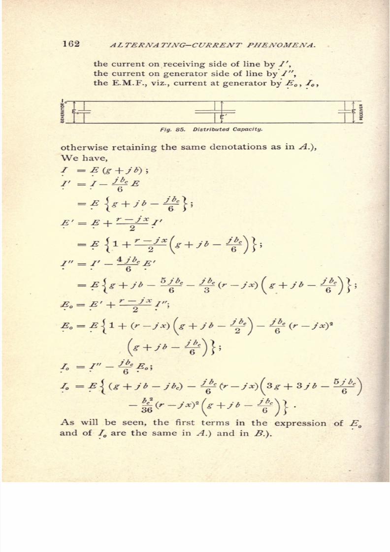
8/2/2019 Charles Steinmetz Theorycalculatio00steiiala
http://slidepdf.com/reader/full/charles-steinmetz-theorycalculatio00steiiala 188/557
162 ALTERNATING-CURRENT PHENOMENA.
the current on receiving side of line by /',
the current on generator side of line by 7",
the E.M.F., viz., current at generator by ,f
,
Iff_L I
85. Distributed Capacity.
otherwise retaining the same denotations as in A.),
We have,
7 =
2" = 1' -
As will beseen,
the first terms in theexpression
of
Eand of I are the same in A.) and in B.).
8/2/2019 Charles Steinmetz Theorycalculatio00steiiala
http://slidepdf.com/reader/full/charles-steinmetz-theorycalculatio00steiiala 189/557
DISTRIBUTED CAPACITY. 163
111. C.) Complete investigation of distributed capacity,
inductance, leakage, and resistance.
In some cases, especially in very long circuits, as in
lines conveying alternating power currents at high potential
over extremely long distances by overhead conductors or un-
derground cables, or with very feeble currents at extremely
high frequency, such as telephone currents, the consideration
of the line resistance which consumes E.M.Fs. in
phasewith the current and of the line reactance which con-
sumes E.M.Fs. in quadrature with the current is not
sufficient for the explanation of the phenomena taking place
in the line, but several other factors have to be taken into
account.
In long lines, especially at high potentials, the electro-
static capacity of the line is sufficient to consume noticeable
currents. The charging current of the line condenser is
proportional to the difference of potential, and is one-fourth
period ahead of the E.M.F. Hence, it will either increase
or decrease the main current, according to the relative phase
of the main current and the E.M.F.
As a consequence, the current will change in intensity
as well as in phase, in the line from point to point ; and the
E.M.Fs. consumed by the resistance and inductance will
therefore also change in phase and intensity from point
to point, being dependent upon the current.
Since no insulator has an infinite resistance, and as at
high potentials not only leakage, but even direct escape of
electricity into the air, takes place by"silent discharge," we
have to recognize the existence of a current approximately
proportional and in phase with the E.M.F. of the line.
This current represents consumption of energy, and is
therefore analogous to the E.M.F. consumed by resistance,
while the condenser current and the E.M.F. of inductance
are wattless.
Furthermore, the alternate current passing overthe line
induces in all neighboring conductors secondary currents,

8/2/2019 Charles Steinmetz Theorycalculatio00steiiala
http://slidepdf.com/reader/full/charles-steinmetz-theorycalculatio00steiiala 190/557
164 ALTERNATING-CURRENT PHENOMENA.
which react
uponthe
primary current,and
therebyintro-
duce E.M.Fs. of mutual inductance into the primary circuit.
Mutual inductance is neither in phase nor in quadrature
with the current, and can therefore be resolved into an
energy component of mutual inductance in phase with the
current, which acts as an increase of resistance, and into
a wattless component in quadrature with the current, which
decreases the self-inductance.
This mutual inductance is not always negligible, as,
for instance, its disturbing influence in telephone circuits
shows.
The alternating potential of the line induces, by electro-
static influence, electric charges in neighboring conductors
outside of the circuit, which retain corresponding opposite
charges on the line wires. This electrostatic influence re-
quires the expenditure of a current proportional to the
E.M.F., and consisting of an energy component, in phase
with the E.M.F., and a wattless component, in quadrature
thereto.
The alternating electromagnetic field of force set up by
the line current produces in some materials a loss of energy
by magnetic hysteresis, or an expenditure of E.M'.F. in
phase with the current, which acts as an increase of re-
sistance. This electromagnetic hysteretic loss may take
place in the conductor proper if iron wires are used, and
will then be very serious at high frequencies, such as those
of telephone currents.
The effect ofeddy
currents hasalready
been referred
to under "mutual inductance," of which it is an energy
component.
The alternating electrostatic field of force expends
energy in dielectrics by what is called dielectric hysteresis.
In concentric cables, where the electrostatic gradient in the
dielectric is comparatively large, the dielectric hysteresis
may at high potentials consume considerable amounts of
The dielectric in the circuit

8/2/2019 Charles Steinmetz Theorycalculatio00steiiala
http://slidepdf.com/reader/full/charles-steinmetz-theorycalculatio00steiiala 191/557
DISTRIBUTED CAPACITY. 165
as
consumption
of a current, whose component in phase
with the E.M.F. is the dielectric energy current, which
may be considered as the power component of the capacity
current.
Besides this, there is the increase of ohmic resistance
due to unequal distribution of current, which, however, is
usually not large enough to be noticeable.
112. This gives, as the most general case, and per unit
length of line :
E.M.Fs. consumed in phase with the current I, and = rl,
representing consumption of energy, and due to :
Resistance, and its increase by unequal current distri-
tribution;
to the energy component of mutual
inductance; to induced currents ; to the energy
component of self-inductance ; or to electromag-
netic hysteresis.
E.M.Fs. consumed in quadrature with the current I, and
= x I, wattless, and due to :
Self-inductance, and Mutual inductance.
Currents consumed in phase with the E.M.F., E, and= gE, representing consumption of energy, and
due to :
Leakage through the insulating material, including
silent discharge; energy component of electro-
static influence ; energy component of capacity, or
of dielectric hysteresis.
Currents consumed in quadrature to the E.M.F., E, and
= bE, being wattless, and due to :
Capacity and Electrostatic influence.
Hence we get fo'ur constants :
Effective resistance, r,
Effective reactance, x,
Effective conductance, g,
b
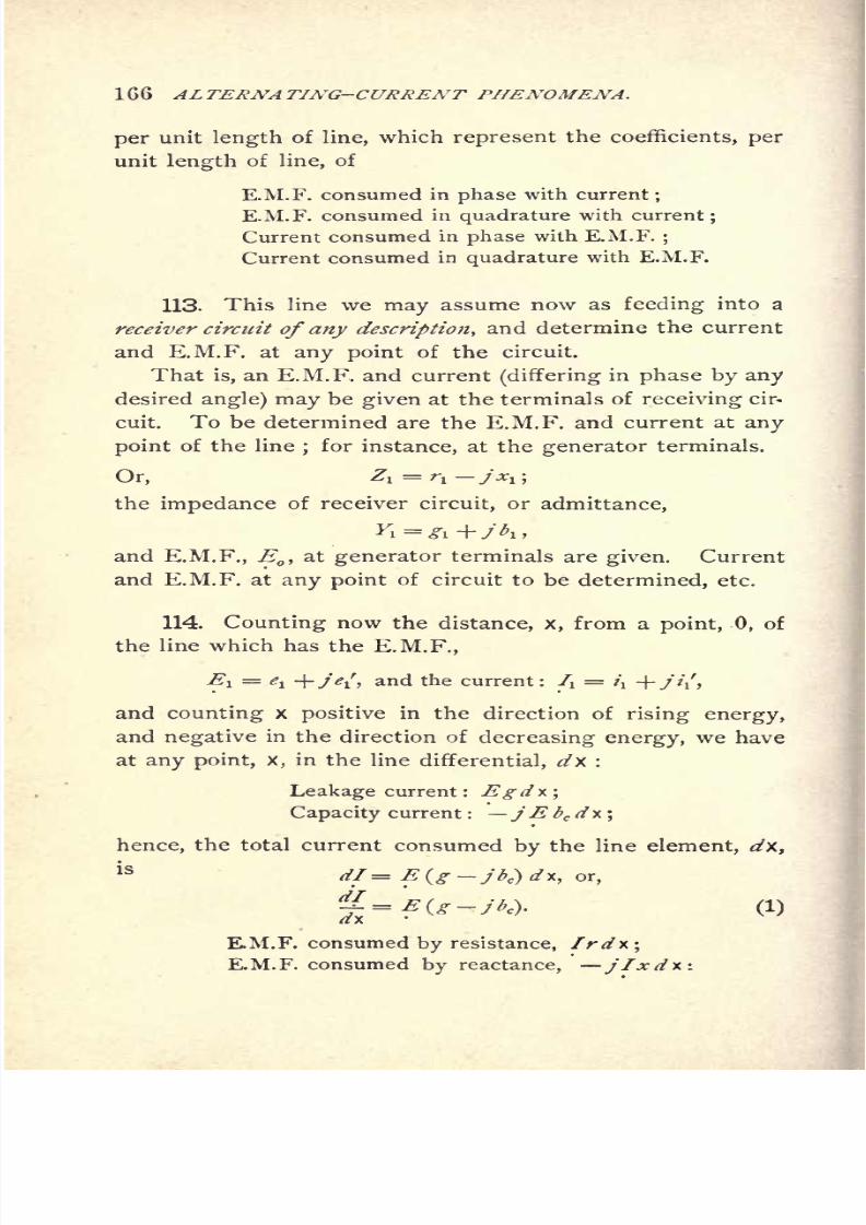
8/2/2019 Charles Steinmetz Theorycalculatio00steiiala
http://slidepdf.com/reader/full/charles-steinmetz-theorycalculatio00steiiala 192/557
1GG ALTERNATING-CURRENT PHENOMENA.
per unit length of line, which represent the coefficients, per
unit length of line, of
E.M.F. consumed in phase with current;
E.M.F. consumed in quadrature with current;
Current consumed in phase with E.M.F.;
Current consumed in quadrature with E.M.F.
113. This line wemay
assume now as
feedinginto a
receiver circuit of any description, and determine the current
and E.M.F. at any point of the circuit.
That is, an E.M.F, and current (differing in phase by any
desired angle) may be given at the terminals of receiving cir-
cuit. To be determined are the E.M.F. and current at any
point of the line;for instance, at the generator terminals.
Or, Zl =rl JXl ;
the impedance of receiver circuit, or admittance,
and E.M.F., E ,at generator terminals are given. Current
and E.M.F. at any point of circuit to be determined, etc.
114. Counting now the distance, x, from a point, 0, ofthe line which has the E.M.F.,
Ei = e\ +Je\i and the current : /i = i\ +///,
and counting x positive in the direction of rising energy,
and negative in the direction of decreasing energy, we have
at any point, X, in the line differential, dx :
Leakage current : JEgdx',
Capacity current : jE bc d x;
hence, the total current consumed by the line element, dx,
is dl= E(g-jbc}d*, or,
d-t=E(g-jbc\ (1)
E.M.F. consumed by resistance, Ird*\E.M.F. consumed reactance,
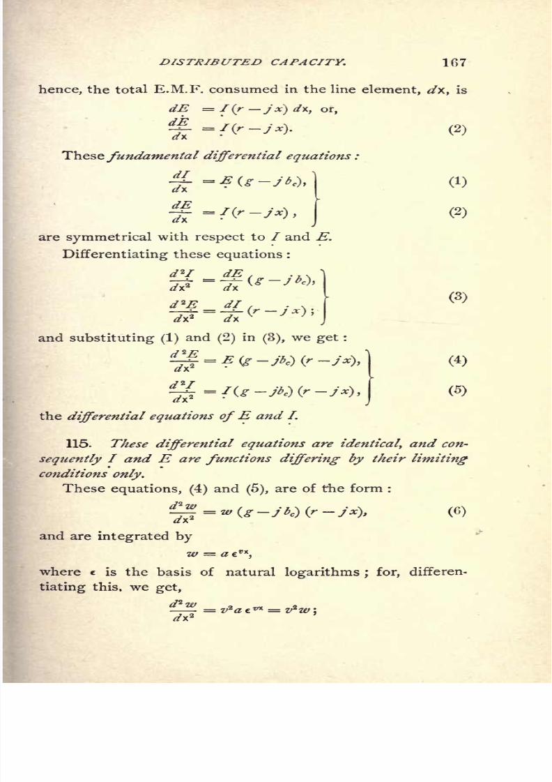
8/2/2019 Charles Steinmetz Theorycalculatio00steiiala
http://slidepdf.com/reader/full/charles-steinmetz-theorycalculatio00steiiala 193/557
DISTRIBUTED CAPACITY. 107
hence, the total E.M.F. consumed in the line element, ^/x, is
dE = I (r j'x) </x, or,
ffi. -I(f-jx). (2)
Thesefundamental differential equations :
*L-E(g-jt,),\ (1)
(2)
are symmetrical with respect to / and E.
Differentiating these equations :
d*I dE ,
and substituting (1)and
(2)in
(3),we get :
(4)
(5)
the differential equations ofE and L
115. These differential equations are identical, and con-
sequently I and E are functions differing by their limiting
conditions only.
These equations, (4) and(5),
are of the form :
(6)
and are integrated by
W = tf 6rx
,
where e is the basis of natural logarithms ; for, differen-
tiating this, we get,

8/2/2019 Charles Steinmetz Theorycalculatio00steiiala
http://slidepdf.com/reader/full/charles-steinmetz-theorycalculatio00steiiala 194/557
168 ALTERNATING-CURRENT PHENOMENA.
hence, z>2 =
(g j bc) (r jx) ;
(7)
or, v = V (g- Jbe) (r joe) \
hence, the general integral is :
tr*.e+-Mr (8)
where a and b are the two constants of integration ;
Substituting
r--/0 (9)
into (7),we have,
(a -JP)* = (g- jbc) (r
- jx) ;
or,
therefore,_ f
);-' (10)
Vl/2 6-
e
/3= Vl/2
substituting (9) into (8) :
= a-cax
(cos/3x /sin^Sx) + ^c~ ax(cos/3x +y sin/3x) ;
/ =(a
x + /5>e~ax
) cos)8x y(aeax ^- ax
)sin /3x (12)
which is the general solution of differential equations (4)
and (5)
Differentiating (8) gives :
hence, substituting, (9) :
(a JP) {(a
x}. (13)
Substituting now / for w, and substituting (13) in(1),
and writing,

8/2/2019 Charles Steinmetz Theorycalculatio00steiiala
http://slidepdf.com/reader/full/charles-steinmetz-theorycalculatio00steiiala 195/557
DISTRIBUTED CAPACITY. 169
we get,
where ^4 and ^ are the constants of integration.
Transformed, we get,
/=JAe a*
(cos )8x j sin 0x) + Bf.~a JP (
'
(cos /?x +/ sin/8x)
>
1^4e ax
(cos /8x y sin
^-.
(cos /3x +y siny8x)
Thus the waves consist of two components, one, with
factor ^e ax, increasing in amplitude toward the generator,
the other, with factor ^e- ax, decreasing toward the genera-
tor. The latter may be considered as a reflected wave.
At the point x = 0.
a-j/3
A-B
n
Thus m (costo j sin G)
= -
and,
m = amplitude.
w = angle of reflection.
These are the general integral equations of the problem.
116. If
/! = /! + /// is the currentat x (15)
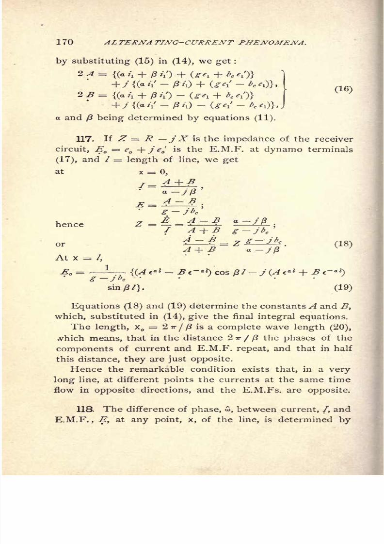
8/2/2019 Charles Steinmetz Theorycalculatio00steiiala
http://slidepdf.com/reader/full/charles-steinmetz-theorycalculatio00steiiala 196/557
170 ALTERNATING-CURRENT PHENOMENA.
by substituting (15) in (14), we get :
2 A ={(a t\ + ft //) + (gev + bc ^')
(16)2 B =
{(a /! + /? //)-
(ge, + /;c ,/)}
+/{(//- 0/0 -(^I'-^a and ft being determined by equations (11).
117. H Z R jXis the impedance of the receiver
circuit, E = e + j>'
is the E.M.F. at dynamo terminals
(17), and / = length of line, we get
at
henceg jbc
or
a-; ft
At X = /,
E
sin/?/}. (19)
Equations (18) and (19) determine the constants A and B,
which, substituted in(14), give the final integral equations.
The length, X = 2 TT/ ft is a complete wave length (20),
,vhich means, that in the distance 2 IT / ft the phases of the
components of current and E.M.F. repeat, and that in half
this distance, they are just opposite.
Hence the remarkable condition exists that, in a very
long line, at different points the currents at the same time
flow in opposite directions, and the E.M.Fs. are opposite.
118. The difference of phase, w, between current, /, and
E.M.F., Ey at any point, x, of the line, is determined by

8/2/2019 Charles Steinmetz Theorycalculatio00steiiala
http://slidepdf.com/reader/full/charles-steinmetz-theorycalculatio00steiiala 197/557
DISTRIBUTED CAPACITY. 171
the equation,
Z?(cos+/sin) =y,:
\j JsTI71
where Z> is a constant.
Hence, w varies from point to point, oscillating around a
medium position, wx ,which it approaches at
infinity.
This difference of phase, C>x ,towards which current and
E.M.F. tend atinfinity, is determined by the expression,
^(cos . .. ,
(/
or, substituting for E and /their values, and since e~ a * = 0,
and A eax
(cos ftx j sin
ft x), cancels, and
D (cos tow +/sin oioc)= 2-p-
hence, tan ^ =~
a
c +^
(21)
This angle, Stx,=
;that is, current and E.M.F. come
more and more in phase with each other, when
abc fig ;that is,
a -T- ft g -r- bc , or,
2a/3
!
*2^*/5
substituting (10), gives,
hence, expanding, r -4- ^ = ^ -f- ^c ; (22)
that is, tJie ratio of resistance to inductance equals the ratio
of leakage to capacity.
This angle, wx,= 45
;that is, current and E.M.F. differ
by th period, if a bc + fig
=a.g + pbc ; or,
=
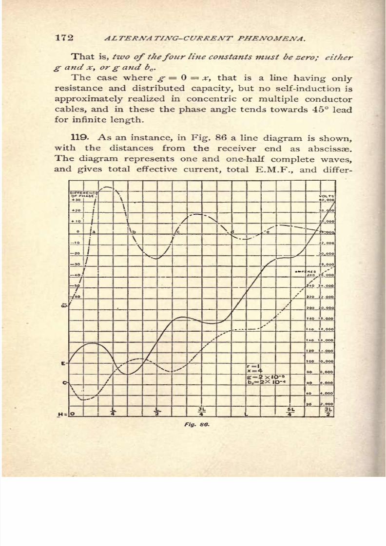
8/2/2019 Charles Steinmetz Theorycalculatio00steiiala
http://slidepdf.com/reader/full/charles-steinmetz-theorycalculatio00steiiala 198/557
172 ALTERNA TING-CURRENT PHENOMENA.
That is, two of thefour line constants must be zero; cither
g and x, org and bc.
The case where g = =x, that is a line having only
resistance and distributed capacity, but no self-induction is
approximately realized in concentric or multiple conductor
cables, and in these the phase angle tends towards 45 lead
for infinite length.
119. As an instance, in Fig. 86 a line diagram is shown,with the distances from the receiver end as abscissae.
The diagram represents one and one-half complete waves,
and gives total effective current, total E.M.F., and differ-
Fig. 86.

8/2/2019 Charles Steinmetz Theorycalculatio00steiiala
http://slidepdf.com/reader/full/charles-steinmetz-theorycalculatio00steiiala 199/557
DISTRIBUTED CAPACITY. 173
ence of phase between both as function of the distance from
receiver circuit ; under the conditions,
E.M.F. at receiving end, 10,000 volts; hence, Ev=e
l= 10,000;
current at receiving end, 65 amperes, with a power factor
of .385.
that is, /=t\+j //
= 25 + 60j ;
line constants per unit length,
r = 1, g = 2 X 10- 5,
hence,
a = 4.95 x 10- 3
,
]
13= 28.36 x 10
- 3
, j-
length of line corresponding to
one
complete period
of the wave= L = = 221.5 =
(^
of propagation.
A = 1.012 - 1.206 y )
B = .812 + .794/ j
These values, substituted, give,
/= {x
(47.3 cos /?x + 27.4 sin fix) e-*
(22.3 cos ftx + 32.6 sinfix)}
+ y (ex
(27.4 cos ftx 47.3 sin ftx) + - x
(32.6 cos y3x 22.3 sin/3x)};
E ={e
ox(6450 cos /3x + 4410 sin
j8x) + c- ax
(3530 cos fix + 4410 sin/?x)}
+ y (eox
(4410 cos /3x 6450 sinx) e~ ax
(4410 cosftx- 3530 sin
/3x)};
tan 5, = ~- ljc
+ PS = _ .073, JJ = - 4.2.
120. As a further instance are shown the characteristic
curves of a transmission line of the relative constants,
r\x\g>.b = % : 32 : 1.25 X 10~ 4
: 25 X 10~ 4
,and e
= 25,000, i = 200 at the receiving circuit, for the con-
ditions,
a, non-inductive load in the receiving circuit, Fig. 87.

8/2/2019 Charles Steinmetz Theorycalculatio00steiiala
http://slidepdf.com/reader/full/charles-steinmetz-theorycalculatio00steiiala 200/557
174 ALTERNATING-CURRENT PHENOMENA.
b, wattless receiving circuit of 90lag, Fig. 88.
c, wattless receiving circuit of 90 lead, Fig. 89.
These curves are determined graphically by constructing
the topographic circuit characteristics in polar coordinates
as explained in Chapter VI., paragraphs 36 and 37, and de-
riving corresponding values of current, potential difference
and phase angle therefrom.
As seen from these diagrams, for wattless
receiving
cir-
cuit, current and E.M.F. oscillate in intensity inversely to
ZJ
7sa
7
rig. 87.

8/2/2019 Charles Steinmetz Theorycalculatio00steiiala
http://slidepdf.com/reader/full/charles-steinmetz-theorycalculatio00steiiala 201/557
DISTRIBUTED CAPACITY. 175
each other, with an amplitude of oscillation gradually de-
creasing when passing from the receiving circuit towards
the generator, while the phase angle between current and
E.M.F. oscillates between lag and lead with decreasing am-
plitude. Approximately maxima and minima of current co-
incide with minima and maxima of E.M.F. and zero phase
angles.
\
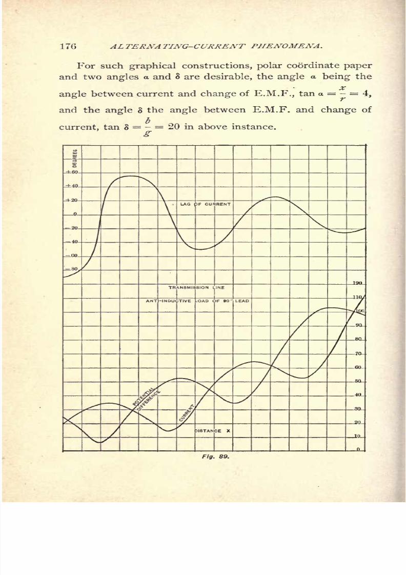
8/2/2019 Charles Steinmetz Theorycalculatio00steiiala
http://slidepdf.com/reader/full/charles-steinmetz-theorycalculatio00steiiala 202/557
176 AL TERNA TING-CURRENT PHENOMENA.
For such graphical constructions, polar coordinate paper
and two angles a and 8 are desirable, the angle a being the
angle between current and change of E.M.F., tan a = - =4,
and the angle 8 the angle between E.M.F. and change of
current, tan 8 = - = 20 in above instance.
g
\
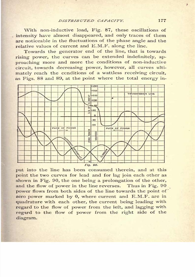
8/2/2019 Charles Steinmetz Theorycalculatio00steiiala
http://slidepdf.com/reader/full/charles-steinmetz-theorycalculatio00steiiala 203/557
DISTRIBUTED CAPACITY. 177
With non-inductive load, Fig. 87, these oscillations of
intensity have almost disappeared, and only traces of them
are noticeable in the fluctuations of the phase angle and the
relative values of current and E.M.F. along the line.
Towards the generator end of the line, that is towards
rising power, the curves can be extendedindefinitely, ap-
proaching more and more the conditions of non-inductive
circuit, towards decreasing power, however, all curves ulti-
mately reach the conditions of a wattless receiving circuit,
as Figs. 88 and 89, at the point where the total energy in-
t
a +120
ISSION LINE
V
Fig. 90.
put into the line has been consumed therein, and at this
point the two curves for lead and for lag join each other as
shown in Fig. 90, the one being a prolongation of the other,
and the flow of power in the line reverses. Thus in Fig. 90
power flows from both sides of the line towards the point of
zero power marked by 0, where current and E.M.F. are in
quadrature with each other, the current being leading with
regard to the flow of power from the left, and lagging with
regard to theflow of
power from the rightside of the
diagram.

8/2/2019 Charles Steinmetz Theorycalculatio00steiiala
http://slidepdf.com/reader/full/charles-steinmetz-theorycalculatio00steiiala 204/557
178 DISTRIBUTED CAPACITY.
121. The following are some particular cases :
A.) Open circuit at end of lines :
x = : /!= 0.
hence,
E = i-r ^{(eax + e- ax
) cos/3x y(cax c- ax
)sin/3x} ;
.?.)Line grounded at end:
A(a/\ -J- /?//) +/ (
a// ^ zi)=
-?
-^-T
-^{(e
ax c- ax) cos/?x >(e
ax + c~ ax) sin)8x};
(T.) Infinitely long conductor :
Replacing x by x, that is, counting the distance posi-
tive in the direction of decreasing energy, we have,
x = oo : 7= 0, E = 0;
hence
and
I = - ^- x
(cos/Sx +y sin/3x),
revolving decay of the electric wave, that is the reflected
wave does not exist.
The total impedance of the infinitely long conductor is
(q-yff)
(g+M+ b? g* + b*
8/2/2019 Charles Steinmetz Theorycalculatio00steiiala
http://slidepdf.com/reader/full/charles-steinmetz-theorycalculatio00steiiala 205/557
ALTERNATING-CURRENT PHENOMENA. 179
The infinitely long conductor acts like an impedance
7 _ -K+ P ?>c _ fig Q-bc
f*+v g* + K'
that is, like a resistance
combined with a reactance
We thus get the difference of phase between E.M.F.
and current,
which is constant at all points of the line.
If g = 0, x = 0, we have,
hence,
tan to = 1, or,
= 45;
that is, current and E.M.F. differ by th period.
D.) Generatorfeeding into closed circuit :
Let x = be the center of cable; then,
hence : E at x =;
which equations are the same as in B, where the line is
grounded at x = 0.
E.) Let the length of a line be one-quarter wave length;
and assume the resistance r and conductance g as negligible
8/2/2019 Charles Steinmetz Theorycalculatio00steiiala
http://slidepdf.com/reader/full/charles-steinmetz-theorycalculatio00steiiala 206/557
180 ALTERNA TING-CURRENT PHENOMENA.
compared with x and bc
.
r=0=g
These values substituted in(11) give
a=0.
(3= V^
Let the E.M.F. at the receiving end of the line be
assumed zero vector
l=
ei= E.M.F. and
fi i'i + ji\.current at end of line x =
= E.M.F. and
S = current at beginning of line
Substituting in (16) these values of Eland 7
:and also r =
=g, we have
From these equations it follows that
which values, together with the foregoing values of Ev Iv r,
g, a, and /8, substituted in (14) reduce these equations to
j (i\ +jiC) \~rs^
8/2/2019 Charles Steinmetz Theorycalculatio00steiiala
http://slidepdf.com/reader/full/charles-steinmetz-theorycalculatio00steiiala 207/557
ALTERNATING-CURRENT TRANSFORMER, 181
Then at x
Hence also
"
and 7 are both in quadrature ahead of <?xand 7j
respectively.
Il
= EQ y
= constant, if 7f = constant. That is, at
constant impressed E.M.F. E& the current 7Xin the receiv-
ing circuit of a line of one-quarter wave length is constant,
and inversely (constant potential constant current trans-
formation by inductive line). In this case, the current 7 at
the beginning of the line is proportional to the load elat the
end of the line.
If XQ= lx = total reactance,
b = lbc= total susceptance of line, then
*<A>=
4-
Instance* = 4, bc= 20 X 10
~ 5
,E = 10,000 V. Hence
/ = 55.5, * = 222, b = .0111, 7j = 70.7, 7 = .00707 e.
122. An interesting application of this method is the
determination of the naturalperiod of a transmission line ;
that is the frequency at which such a line discharges an
accumulated charge of atmospheric electricity (lightning),
or oscillates at a suddenchange
ofload,
as a break of cir-
cuit.

8/2/2019 Charles Steinmetz Theorycalculatio00steiiala
http://slidepdf.com/reader/full/charles-steinmetz-theorycalculatio00steiiala 208/557
182 ALTERNATING-CURRENT PHENOMENA.
The discharge of a condenser through a circuit contain-
ing self-induction and resistance is oscillating (provided that
the resistance does not exceed a certain critical value de-
pending upon the capacity and the self-induction). That is,
the discharge current alternates with constantly decreasing
intensity. The frequency of this oscillating discharge de-
pends upon the capacity, C, and the self-induction, L, of the
circuit, and to a much lesser extent
upon
the resistance, so
that if the resistance of the circuit is not excessive the fre-
quency of oscillation can, by neglecting the resistance, be
expressed with fair, or even close, approximation by the
formula -
An electric transmission line represents a capacity as well
as a self-induction;and thus when charged to a certain
potential, for instance, by atmospheric electricity, as by in-
duction from a thunder-cloud passing over or near the line,
the transmission line discharges by an oscillating current.
Such a transmission line differs, however, from an ordi-
nary condenser, in that with the former the capacity and
the self-induction are distributed along the circuit.
In determining the frequency of the oscillating discharge
of such a transmission line, a sufficiently close approximation
is obtained by neglecting the resistance of the line, which,
at the relatively high frequency of oscillating discharges,
is small compared with the reactance. This assumption
means that the dying out of the discharge current through
the influence of the resistance of the circuit is neglected,
and the current assumed as an alternating current of ap-
proximately the same frequency and the same intensity as
the initial waves of the oscillating discharge current. Bythis means the problem is essentially simplified.
Let / = total length of a transmission line,
r = resistanceper
unitlength,
x = reactance per unit length= 2 ?r NL.

8/2/2019 Charles Steinmetz Theorycalculatio00steiiala
http://slidepdf.com/reader/full/charles-steinmetz-theorycalculatio00steiiala 209/557
DISTRIBUTED CAPACITY. 183
where L = coefficient of self-induction or inductance per unit
length ;
g = conductance from line to return (leakage and dis-
charge into theair) per unit length ;
b = capacity susceptance per unit length= 2 TT NC
where C = capacity per unit length.
x = the distance from the beginning of the line,
We have then the equations :
The E.M.F.,
(^ eax _ ^e -ax) CQS x _j (4
g jb I+ ^e~
ax)sin /3x
the current,
1^(Ae a* + ^e~ ax
)COS /3x y (^4e
where,
,(14.)
(r1 + ^c
2
) + (^r-
'
(11.)
c = base of the natural logarithms, and A and B integration
constants.
Neglecting the line resistance, r = 0, and the conduc-
tance (leakage, etc.), g=0, gives,
These values substituted in (14) give,
J-J-\(A
-B} cos ^fbx^ -j (A + H) sin
/ = -4= J (^ + -ff) cos V^x y (<4 - B) sin;
J
8/2/2019 Charles Steinmetz Theorycalculatio00steiiala
http://slidepdf.com/reader/full/charles-steinmetz-theorycalculatio00steiiala 210/557
184 ALTERNATING-CURRENT PHENOMENA.
If the discharge takes place at the point : x = 0, that is,
if the distance is counted from the discharge point to theend of the line
;x =
/, hence :
At x = 0, E =0,
Atx=/, 7=0.
Substituting these values in (25) gives,
For x = 0,
^-7^ = A = Bwhich reduces these equations to,
E = sin Nbx xb
\
7= -^4^= cos V&t: x
VA*I
and atx
= 0,
At x =/, / = 0, thus, substituted in (26),
cos V^/ = (28.)
hence :
V^/^2
**1
)", 1 = 0,1, 2,... (29.)
that is, *Jbx I is an odd multiple of ^ And at x =/,
2t
O A
Substituting in (29) the values,
we have,
hence,
^=M+l
(31.)4/VCZ
8/2/2019 Charles Steinmetz Theorycalculatio00steiiala
http://slidepdf.com/reader/full/charles-steinmetz-theorycalculatio00steiiala 211/557
DISTRIBUTED CAPACITY. 185
the frequency of the oscillating discharge,
where k = 0, 1, 2. . . .
That is, the oscillating discharge of a transmission line
of distributed capacity does not occur at one definite fre-
quency (as that of a condenser), but the line can discharge
at any one of an infinite number of frequencies, which are
the odd multiples of the fundamental discharge frequency,
*-I7^z (32'>
Since
C = 1C = total capacity of transmission line, )
L = IL = total self-inductance of transmission line, J
^ ''
we have,
2, + 1
-= the frequencyof
oscillation, (34.)
or natural period of the line, and
NI -- the fundamental,-
or lowest natural period of the line.
From(30), (33),
and(34),
b = 2irNC=2/ \T (36-)
and from(29),
V^ = (2
^2f
/)7r
-<37 ')
These substituted in (26) give,
f- (38.)
4/7 (2 + l)7rx/=(2TTi)-^
cosL^HThe oscillating discharge of a line can thus follow any of
the forms given by making k 0, 1, 2, 3 . . .in equation
(38).
Reduced from symbolic representation to absolute values

8/2/2019 Charles Steinmetz Theorycalculatio00steiiala
http://slidepdf.com/reader/full/charles-steinmetz-theorycalculatio00steiiala 212/557
186 ALTERNATING-CURRENT PHENOMENA.
by multiplying E with cos 2 * Nt and / with sin 2 TT A7/ and
omittingj, and substituting A7
"
from equation (34), we have,
(2+l)7rxsin
JT- -cos2/
where ^4 is an integration constant, depending upon the
initial distribution of voltage, before the discharge, and
/ = time after discharge.
123. The fundamental discharge wave is thus, for k = 0,
47. Lo . . 7TX 7T/
-^ A sin 7^C 2/
. o . . 7TX= \ -^ A sin 7^ cos
TT V
4 / -
_,7T X 7T/
fi= A cos 7n
- sin -
With this wave the current is a maximum at the begin-
ning of the line : x = 0, and gradually decreases to zero at
the end of the line : x = /.
The voltage is zero at the beginning of the line, and
rises to a maximum at the end of the line.
Thus the relative intensities of current and potential
along the line are as represented by Fig. 91, where the cur-
is shown as /, the potential as E.
The next higher discharge frequency, for : k 1, gives :
47. [Ln . .
3v_(41.)
4/" " - '
/,= o- A cos n 7
27
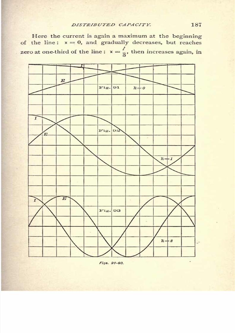
8/2/2019 Charles Steinmetz Theorycalculatio00steiiala
http://slidepdf.com/reader/full/charles-steinmetz-theorycalculatio00steiiala 213/557
DISTRIBUTED CAPACITY. 187
Here the current is again a maximum at the beginning
of the line : x = 0, and gradually decreases, but reaches
zero at one-third of the line : x = _, then increases again, ino
Fig. H----0
Fig.
\\
\
\1
Figs. 91-93.
8/2/2019 Charles Steinmetz Theorycalculatio00steiiala
http://slidepdf.com/reader/full/charles-steinmetz-theorycalculatio00steiiala 214/557
188 ALTERNATING CURRENT-PHENOMENA.
the opposite direction, reaches a second but opposite maxi-
2/
mum at two-thirds of the line : x = ^ , and decreases too
zero at the end of the line. There is thus a nodal point of
current at one-third of the line.
The E.M.F. is zero at the beginning of the line : x = 0,
rises to a maximum at one-third of the line : x = -,de-
2/3
creases to zero at two-thirds of the line: x =
IT >
and rises
again to a second but opposite maximum at the end of the
line: x = /. The E.M.F. thus has a nodal point at two-
thirds of the line.
The discharge waves : k = 1, are shown in Fig. 92,
those with k = 2, with two nodal points, in Fig. 93.
Thus k is the number of nodal points or zero points of
current and of E.M.F. existing in the line (not counting
zero points at the ends of the line, which of course are not
nodes).
In case of a lightning discharge the capacity C is the
capacity of the line against ground, and thus has no direct
relation to the capacity of the line conductor against its
return. The same applies to the inductance L.
If d = diameter of line conductor,
D = distance of conductor above ground,
and / = length of conductor,
the capacity is,
1.11 x 10- 6/ ,.~
the self-inductance,
The fundamental frequency of oscillation is thus, by
substituting (42) in (35),
8/2/2019 Charles Steinmetz Theorycalculatio00steiiala
http://slidepdf.com/reader/full/charles-steinmetz-theorycalculatio00steiiala 215/557
DISTRIBUTED CAPACITY. 189
That is, the frequency of oscillation of a line discharging
toground
is
independentof the size of line wire and its
distance from the ground, and merely depends upon the
length / of the line, being inversely proportional thereto.
We thus get the numerical values,
Length of line
10 20 30 40 50 60 80 100 miles.
= 1.6 3.2 4.8 6.4 8 9.6 12.8 16 x 106cm..
hence frequency,
N-i= 4680 2340 1560 1170 937.5 780 585 475
cycles-..
As seen, these frequencies are comparatively low, and
especially with very long lines almost approach alternator
frequencies.
The higher harmonics of the oscillation are the odd!
multiples of these frequencies.
Obviously all these waves of different frequencies repre-
sented in equation (39) can occur simultaneously in the
oscillating discharge of a transmission line, and in general
the oscillating discharge of a transmission line is thus of
the form,
(by substituting: ak =*
j
where a^ asay . . . are constants depending upon the
initial distribution of potential in the transmission line, at
the moment of discharge, or at / = 0, and calculated there-
from.
8/2/2019 Charles Steinmetz Theorycalculatio00steiiala
http://slidepdf.com/reader/full/charles-steinmetz-theorycalculatio00steiiala 216/557
190 ALTERNA TING-CURRENT PHENOMENA .
124. As an instance the following discharge equation
of a line charged to a uniform potential e over, its entire
length, and then discharging at x = 0, has been calculated.
The harmonics are determined up to the 11 that is, av
a& #5>av a
9>an-
These six unknown quantities require six equations, which
/ 2/ 3/ 4/ 5/ 6/are given by assuming E = e for x =
g,_,_,_,_,_.
At / = 0, E = e, equation (44) assumes the form
4 / HT(
. TTX,
. 3 TTXe =
V ?j
ism
27+ *
3sm
~27+ ' ' ' ' + *u
(45.)
/ 2/ 6/Substituting herein for x the values :
-, ,
. . .
gives six equations for the determination of av <73
. . . an .
These equations solved give,
E = e (1.26 sin w cos $ + .40 sin 3 w cos 3<f + .22 sin ^
5 w cos 5<^ + .12 sin 7 o> cos 7 < + .07 sin 9 co
cos 9 ^ + .02 sin 11 o> cos 11^>
5Lcos 5 <o sin 5
<^ + .12 cos 7 o> sin 7 < + .07 cos
9 to sin 9 < + .02 cos 11 o> sin 11</>
7= e i/5(1.26
cos o> sin <
+.40 cos 3 w sin 3 <
+.22
V 7rt
,(46.)
where,
"-57 1
r<47
')
Instance, .
Length of line, / = 25 miles = 4 x 106 cm.
Size of wire : No. 000 B. & S. G., thus : d = 1 cm.
Height above ground : D 18 feet = 550 cm.
Let e = 25,000 volts = potential of line in the moment of
-discharge.
8/2/2019 Charles Steinmetz Theorycalculatio00steiiala
http://slidepdf.com/reader/full/charles-steinmetz-theorycalculatio00steiiala 217/557
DISTRIBUTED CAPACITY. 191
We then have,
E = 31,500 sin w cos<fr + 10,000 sin 3 <o cos 3 < + 5500 sin
5 o> cos 5<J> + 3000 sin 7 o> cos 7 < -j- 1750 sin 9 o> cos
9 < + 500 sin 11 w cos 11 <.
/= 61.7 cos w sin < + 19.6 cos 3 o> sin 3 < + 10.8 cos 5 sin
5 < + 5.9 cos 7 CD sin 7</> + 3.4 cos 9 to sin 9 < + 1.0
cos 11 <o sin 11<J>.
<o= .39 .r 10
- 6
</>= 1.18/ 10+ 4
A simple harmonic oscillation as a line discharge would
require a sinoidal distribution of potential on the trans-
mission line at the instant of discharge, which is not proba-
ble, so that probably all lightning discharges of transmission
lines or oscillations
produced bysudden
changesof circuit
conditions are complex waves of many harmonics, which in
their relative magnitude depend upon the initial charge and
its distribution that is, in the case of the lightning dis-
charge, upon the atmospheric electrostatic field of force.
The fundamental frequency of the oscillating discharge
of a transmission line is relatively low, and of not much
higher magnitude than frequencies in commercial use in
alternating current circuits. Obviously, the more nearly
sinusoidal the distribution of potential before the discharge,
the more the low harmonics predominate, while a very un-
equal distribution of potential, that is a very rapid change
along the line, as caused for instance by a sudden short
circuit rupturing itself instantly, causes the higher harmo-
nics to predominate, which as a rule are more liable to cause
excessive rises of voltage by resonance.
125. As has been shown, the electric distribution in a
transmission line containing distributed capacity, self-induc-
tion, etc., can be represented either by a polar diagram
with the
phase
as
amplitude,
and theintensity
as radius
vector, as in Fig. 34, or by a rectangular diagram with the

8/2/2019 Charles Steinmetz Theorycalculatio00steiiala
http://slidepdf.com/reader/full/charles-steinmetz-theorycalculatio00steiiala 218/557
192 ALTERNATING-CURRENT PHENOMENA.
distance as abscissae, and the intensity as ordinate, as in
Fig. 35 and in the preceding paragraphs.In the former case, the consecutive points of the circuit
characteristic refer to consecutive points along the trans-
mission line, and thus to give a complete representation of
the phenomenon, should not be plotted in one plane but in
front of each other by their distance along the transmission
line. That is, if 0, 1, 2, etc., are the polar vectors in Fig.
34, corresponding to equi-distant points of the transmission
line, 1 should be in a plane vertically in front of the plane
of 0, 2 by the same distance in front of 1, etc.
In Fig. 35 the consecutive points of the circuit charac-
teristic represent vectors of different phase, and thus should
be rotated out of the plane around the zero axis by the
angles of phase difference, and then give a length view of
the same space diagram, of which Fig. 34 gives a view along
the axis.
Thus, the electric distribution in a transmission line can
be represented completely only by a space diagram, and as
complete circuit characteristic we get for each of the lines
a screw shaped space curve, of which the distance along the
axis of the screwrepresents
the distance
along
the transmis-
sion line, and the distance of each point from the axis rep-
resents by its direction the phase, and by its length the
intensity.
Hence the electric distribution in a transmission line
leads to a space problem of which Figs. 34 and 35 are par-
tial views. The single-phase line is represented by a double
screw, the three-phase line by a triple screw, and the quarter-
phase four-wire line by a quadruple screw. In the symbolic
expression of the electric distribution in the transmission
line, the real part of the symbolic equation represents a pro-
jection on a plane passing through the axis of the screw,
and the imaginary part a projection on a plane perpendicular
to the first, and also passing through the axis of the screw.

8/2/2019 Charles Steinmetz Theorycalculatio00steiiala
http://slidepdf.com/reader/full/charles-steinmetz-theorycalculatio00steiiala 219/557
ALTERNATING-CURRENT TRANSFORMER. 193
CHAPTER XIV.
THE ALTERNATING-CURRENT TRANSFORMER.
126. The simplest alternating-current apparatus is the
transformer. It consists of a magnetic circuit interlinked
with two electric circuits, a primary and a secondary. The
primary circuit is excited by an impressed E.M.F., while in
the secondary circuit an E.M.F. is induced. Thus, in the
primary circuit power is consumed, and in the secondary
a corresponding amount of power is produced.Since the same magnetic circuit is interlinked with both
electric circuits, the E.M.F. induced per turn must be the
same in the secondary as in the primary circuit; hence,
the primary induced E.M.F. being approximately equal to
the impressed E.M.F., the E.M.Fs. at primary and at sec-
ondary terminals have approximately the ratio of their
respective turns. Since the power produced in the second-
ary is approximately the same as that consumed in the
primary, the primary and secondary currents are approxi-
mately in inverse ratio to the turns.
127. Besides the magnetic flux interlinked with both
electric circuits which flux, in a closed magnetic circuit
transformer, has a circuit of low reluctance a magnetic
cross-flux passes between the primary and secondary coils,
surrounding one coil only, without being interlinked with
the other. This magnetic cross-flux is proportional to the
current flowing in the electric circuit, or rather, the ampere-
turns or M.M.F. increase with the increasing load on the
transformer, and constitute what is called the self-induc-
tance of the transformer;while the flux surrounding both

8/2/2019 Charles Steinmetz Theorycalculatio00steiiala
http://slidepdf.com/reader/full/charles-steinmetz-theorycalculatio00steiiala 220/557
194 ALTERNATING-CURRENT PHENOMENA.
coils may be considered as mutual inductance. This cross-
flux of self-induction does not induce E.M.F. in the second-
ary circuit, and is thus, in general, objectionable, by causing
a drop of voltage and a decrease of output. It is this
cross-flux, however, or flux of self-inductance, which is uti-
lized in special transformers, to secure automatic regulation,
for constant power, or for constant current, and in this
case is exaggerated by separating primary and secondary
coils. In the constant potential transformer however, the
primary and secondary coils are brought as near together as
possible, or even interspersed, to reduce the cross-flux.
As will be seen by the self-inductance of a circuit, not
the total flux produced by, and interlinked with, the circuit
is understood, but only that (usually small) part of the flux
which surrounds one circuit withoutinterlinking
with the
other circuit.
128. The alternating magnetic flux of the magnetic
circuit surrounding both electric circuits is produced by
the combined magnetizing action of the primary and of the
secondary current.
This magnetic flux is determined by the E.M.F. of the
transformer, by the number of turns, and by the frequency.
If
< = maximum magnetic flux,
N= frequency,
n = number of turns of the coil;
the E.M.F. induced in this coil is
E= V2 * JVfc * 10- 8 = 4.44 .Afo* 10 -'volts;
hence, if the E.M.F., frequency, and number of turns are
determined, the maximum magnetic flux is
To produce the magnetism, $, of the transformer, a
M.M.F. of 5 ampere-turns is required, which is determined

8/2/2019 Charles Steinmetz Theorycalculatio00steiiala
http://slidepdf.com/reader/full/charles-steinmetz-theorycalculatio00steiiala 221/557
ALTERNATING-CURRENT TRANSFORMER. 195
by the shape and the magnetic characteristic of the iron, in
the manner discussed in Chapter X.For instance, in the closed magnet circuit transformer,
the maximum magnetic induction is ($> = & /S, where S= the cross-section of magnetic circuit.
129. To induce a magnetic density, ($>, a M.M.F. of 3CTO
ampere-turns maximum is required, or, 3COT /
V2 ampere-
turns effective, per unit length of the magnetic circuit ;
hence, for the total magnetic circuit, of length, /,
/3C& = :r- ampere-turns ;
*V2
where n = number of turns.
At no load, or open secondary circuit, this M.M.F., CF, is
furnished by the exciting current, T00 , improperly called the
leakage current, of the transformer;
that is, that small
amount of primary current which passes through the trans-
former at open secondary circuit.
In a transformer with open magnetic circuit, such as
the "hedgehog" transformer, the M.M.F., &, is the sum
of the M.M.F. consumed in the iron and in the air part of
the magnetic circuit (see Chapter X.).
The energy of the exciting current is the energy con-
sumed by hysteresis and eddy currents and the small ohmic
loss.
The exciting currentis
not a sine wave, but is, at least
in the closed magnetic circuit transformer, greatly distorted
by hysteresis, though less so in the open magnetic circuit
transformer. It can, however, be represented by an equiv-
alent sine wave, f00 ,of equal intensity and equal power with
the distorted wave, and a wattless higher harmonic, mainly
of triple frequency.
Since the higher harmonic is small compared with the
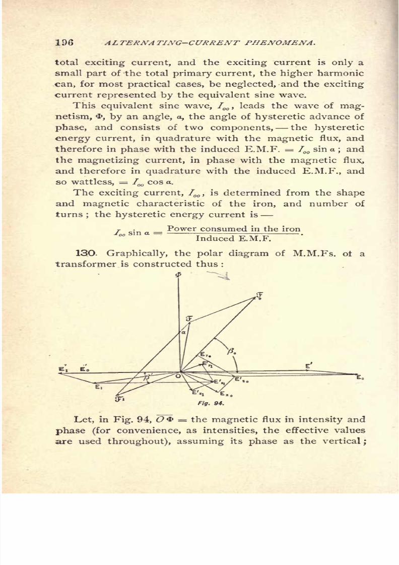
8/2/2019 Charles Steinmetz Theorycalculatio00steiiala
http://slidepdf.com/reader/full/charles-steinmetz-theorycalculatio00steiiala 222/557
196 ALTERNATING-CURRENT PHENOMENA.
total exciting current, and the exciting current is only a
small part of the total primary current, the higher harmonic
.can, for most practical cases, be neglected, and the exciting
current represented by the equivalent sine wave.
This equivalent sine wave, 7^, leads the wave of mag-
netism, 3>, by an angle, a, the angle of hysteretic advance of
phase, and consists of two components, the hysteretic
energy current, in quadrature with the magnetic flux, and
therefore in phase with the induced E.M.F. = I00
sin a; and
the magnetizing current, in phase with the magnetic fluXj
and therefore in quadrature with the induced E.M.F., and
so wattless, = I00cos a.
The exciting current, 700 ,
is determined from the shape
and magnetic characteristic of the iron, and number of
turns;
the hysteretic energy current is
Power consumed in the ironI00 sin aInduced E.M.F.
130. Graphically, the polar diagram of M.M.Fs. ot a
transformer is constructed thus :
Fig. 94.
Let, in Fig. 94, O = the magnetic flux in intensity and
phase (for convenience, as intensities, the effective values
are used throughout), assuming its phase as the vertical;

8/2/2019 Charles Steinmetz Theorycalculatio00steiiala
http://slidepdf.com/reader/full/charles-steinmetz-theorycalculatio00steiiala 223/557
ALTERNATING-CURRENT TRANSFORMER. 197
that is, counting the time from the moment where the
rising magnetism passes its zero value.
Then the resultant M.M.F. is represented by the vector
QS, leading O<b by the angle &O = a.
The induced E.M.Fs. have the phase 180, that is, are
plotted towards the left, and represented by the vectors
OZT; and OE.
If, now, ft'= angle of lag in the secondary circuit, due
to the total (internal and external) secondary reactance, the
secondary current II ,
and hence the secondary M.M.F.,
JF1= j /L,will lag behind [ by an angle ft
1
,and have the
phase, 180 + ft', represented by the vector O^1
. Con-
structing a parallelogram of M.M.Fs., with Off as a diag-
onal and Oif1
as one side, the other side or O'S is the
primary M.M.F.,in
intensity and phase, and hence, dividing
by the number of primary turns, n ,the primary current is
/.-*./*..To complete the diagram of E M.Fs.
,we have now,
In the primary circuit :
E.M.F. consumed by resistance is 7 r,in phase with fot and
represented by the vector OEr
E.M.F. consumed by reactance is IoX ,90 ahead of I ,
and
represented by the vector OEx;
E.M.F. consumed by induced E.M.F. is E', equal and oppo-
site to E'o, and represented by the vector Off.
Hence, the total primary impressed E.M.F. by combina-
tion of OEr,OEx
,and OE' by means of the parallelo-
gramof E.M.Fs. is,
E = ~OE,
and the difference of phase between the primary impressed
E.M.F. and the primary current is
ft= E O5 .
In the secondary circuit :
Counter E.M.F. of resistanceis
1^ in opposition with Ivand represented by the vector OJS'r^ ;
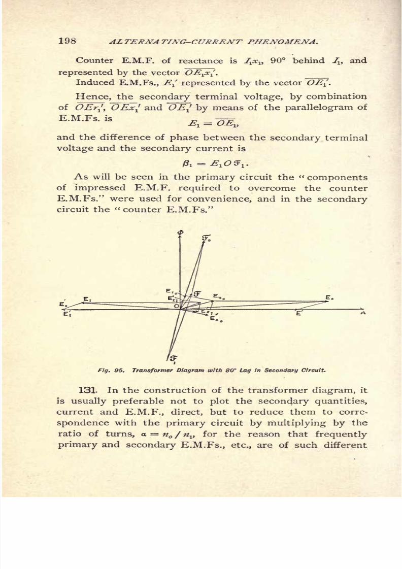
8/2/2019 Charles Steinmetz Theorycalculatio00steiiala
http://slidepdf.com/reader/full/charles-steinmetz-theorycalculatio00steiiala 224/557
198 ALTERNA TING-CURRENT PHENOMENA,
90 behind 7X ,
andounter E.M.F. of reactance is
represented by the vector OE^x^Induced E.M.Fs., E( represented by the vector OE-[.
Hence, the secondary terminal voltage, by combination
of OEr^ OEx{ and OE^ by means of the parallelogram of
E.M.Fs. is -==A = MII
and the difference of phase between the secondary terminal
voltage and the secondary current is
As will be seen in the primary circuit the "components
of impressed E.M.F. required to overcome the counter
E.M.Fs." were used for convenience, and in the secondary
circuit the "counter E.M.Fs."
E r ,
Fig. 95. Transformer Diagram with 80 Lag in Secondary Circuit.
131. In the construction of the transformer diagram, it
is usually preferable not to plot the secondary quantities,
current and E.M.F., direct, but to reduce them to corre-
spondence with the primary circuit by multiplying by the
ratio of turns, a = n / nv for the reason that frequently
primary and secondary E.M.Fs., etc., are of such different
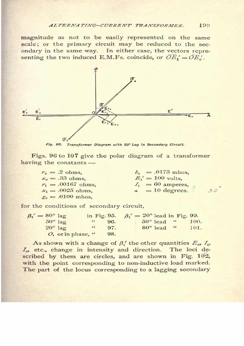
8/2/2019 Charles Steinmetz Theorycalculatio00steiiala
http://slidepdf.com/reader/full/charles-steinmetz-theorycalculatio00steiiala 225/557
AL TERA?A TING-CURRENT TRANSFORMER. 19!)
magnitude as not to be easily represented on the same
scale; or the primary circuit may be reduced to the sec-
ondary in the same way. In either case, the vectors repre-
senting the two induced E.M.Fs. coincide, or OE-^= OE^.
Fig. 96. Transformer Diagram with 50 Lag in Secondary Circuit.
Figs. 96 to 107 give the polar diagram of a transformer
having the constants
r = .2 ohms,
x = .33 ohms,
f! = .00167 ohms,
*! = .0025 ohms,
g = .0100 mhos,
for the conditions of secondary circuit,
= .0173 mhos,
= 100 volts,
= 60 amperes,
=10 degrees. ?
20 lead in Fig. 99.
50 lead"
100.
80 lead"
101.
ft'= 80 lag in Fig. 95.
50 lag"
96.
20 lag"
97.
O, or in phase,"
98.
As shown with a change of /?/ the other quantities E ,Iv
I, etc., change in intensity and direction. The loci de-
scribed by them are circles, and are shown in Fig. 102,
with the point corresponding to non-inductive load marked.
The part of the locus corresponding to a lagging secondary

8/2/2019 Charles Steinmetz Theorycalculatio00steiiala
http://slidepdf.com/reader/full/charles-steinmetz-theorycalculatio00steiiala 226/557
200 ALTERNATING-CURRENT PHENOMENA.
Fig. 97. Transformer Diagram with 20 Lag in Secondary Circuit
Fig. 98. Transformer Diagram with Secondary Current in Phase with E.M.F.
Fig. 99. Transformer Diagram with 20 Lead in Secondary Current.
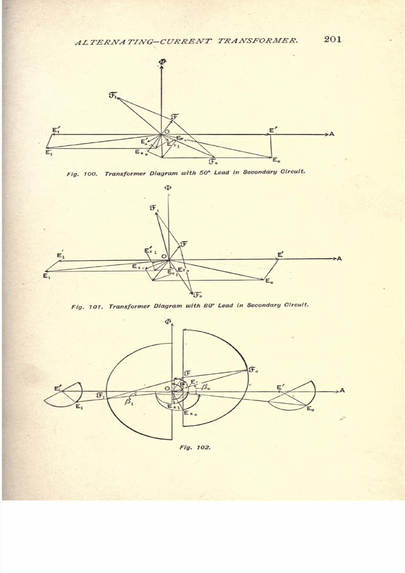
8/2/2019 Charles Steinmetz Theorycalculatio00steiiala
http://slidepdf.com/reader/full/charles-steinmetz-theorycalculatio00steiiala 227/557
ALTERNATING-CURRENT TRANSFORMER. 201
(ToEO
Fig. 100. Transformer Diagram with 50 Lead in Secondary Circuit.
Fig. 101. Transformer Diagram with 80 Lead in Secondary Circuit.
Fig. 102.

8/2/2019 Charles Steinmetz Theorycalculatio00steiiala
http://slidepdf.com/reader/full/charles-steinmetz-theorycalculatio00steiiala 228/557
202 AL TERNA TING-CURRENT PHENOMENA.
current is shown in thick full lines, and the part correspond-
ing to leading current in thin full lines.
132. This diagram represents the condition of constant
secondary induced E.M.F., "/,that is, corresponding to a
constant maximum magnetic flux.
By changing all the quantities proportionally from the
diagram of Fig. 102, the diagrams for the constant primary
impressed E.M.F. (Fig. 103), and for constant secondary
terminal voltage (Fig. 104), are derived. In these cases,
the locus gives curves of higher order.
Fig. 103.
Fig. 105 gives the locus of the various quantities when
the load is changed from full load, /j= 60 amperes in a
non-inductive secondary external circuit to no load or open
circuit.
a.) By increase of secondary resistance; b.} by increase
of secondary inductive reactance; c.) by increase of sec-
ondary capacity reactance.
As shown ina.),
the locus of the secondary terminal vol-
tage, J5lt
and thus of E, etc., are straight lines; and in
b.)and
c.}, parts of one and the same circle a.} is shown
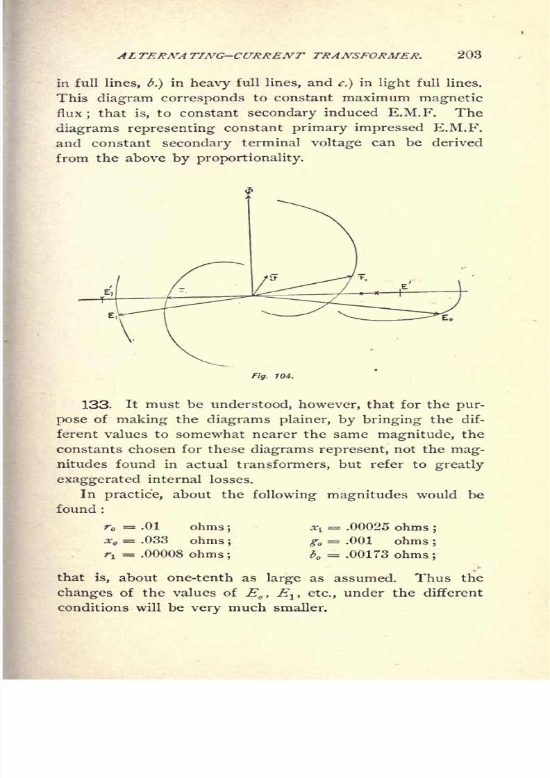
8/2/2019 Charles Steinmetz Theorycalculatio00steiiala
http://slidepdf.com/reader/full/charles-steinmetz-theorycalculatio00steiiala 229/557
AL TERNA TING-CURRENT TRANSFORMER. 203
in full lines, b.}in heavy full lines, and
c.}in light full lines.
This diagram corresponds to constant maximum magnetic
flux;that is, to constant secondary induced E.M.F. The
diagrams representing constant primary impressed E.M.F.
and constant secondary terminal voltage can be derived
from the above by proportionality.
Fig. 104.
133. It must be understood, however, that for the pur-
pose of making the diagrams plainer, by bringing the dif-
ferent values to somewhat nearer the same magnitude, the
constants chosen for these diagrams represent, not the mag-
nitudes found in actual transformers, but refer to greatly
exaggerated internal losses.
Inpractice,
about thefollowing magnitudes
would be
found :
r = .01 ohms;
x = .033 ohms;
ri= .00008 ohms
j
#! = .00025 ohms;
g = .001 ohms;
b = .00173 ohms;
that is, about one-tenth as large as assumed. Thus the
changes of the values of E,E
lt etc., under the different
conditions will be very much smaller.

8/2/2019 Charles Steinmetz Theorycalculatio00steiiala
http://slidepdf.com/reader/full/charles-steinmetz-theorycalculatio00steiiala 230/557
204 ALTERNATING-CURRENT PHENOMENA.
Symbolic Method.
134. In symbolic representation by complex quantities
the transformer problem appears as follows :
The exciting current, 700 ,
of the transformer depends
upon the primary E.M.F., which dependance can be rep-
resented by an admittance, the "primary admittance,"
f tne transformer.
Fig. 105.
The resistance and reactance of the primary and the
secondary circuit are represented in the impedance by
Z =r - jx ,and Z
l=r
l- jxl
.
Within the limited range of variation of the magnetic
density in a constant potential transformer, admittance and
impedance can usually, and with sufficient .exactness, be
considered as constant.
Let
n = number of primary turns in series;
#1 = number of secondary turns in series;
a = = ratio of turns;
Y = g 4- jb =primary admittance
Exciting current . ~i I
Primary counter E.M.F.' .VVWvVl
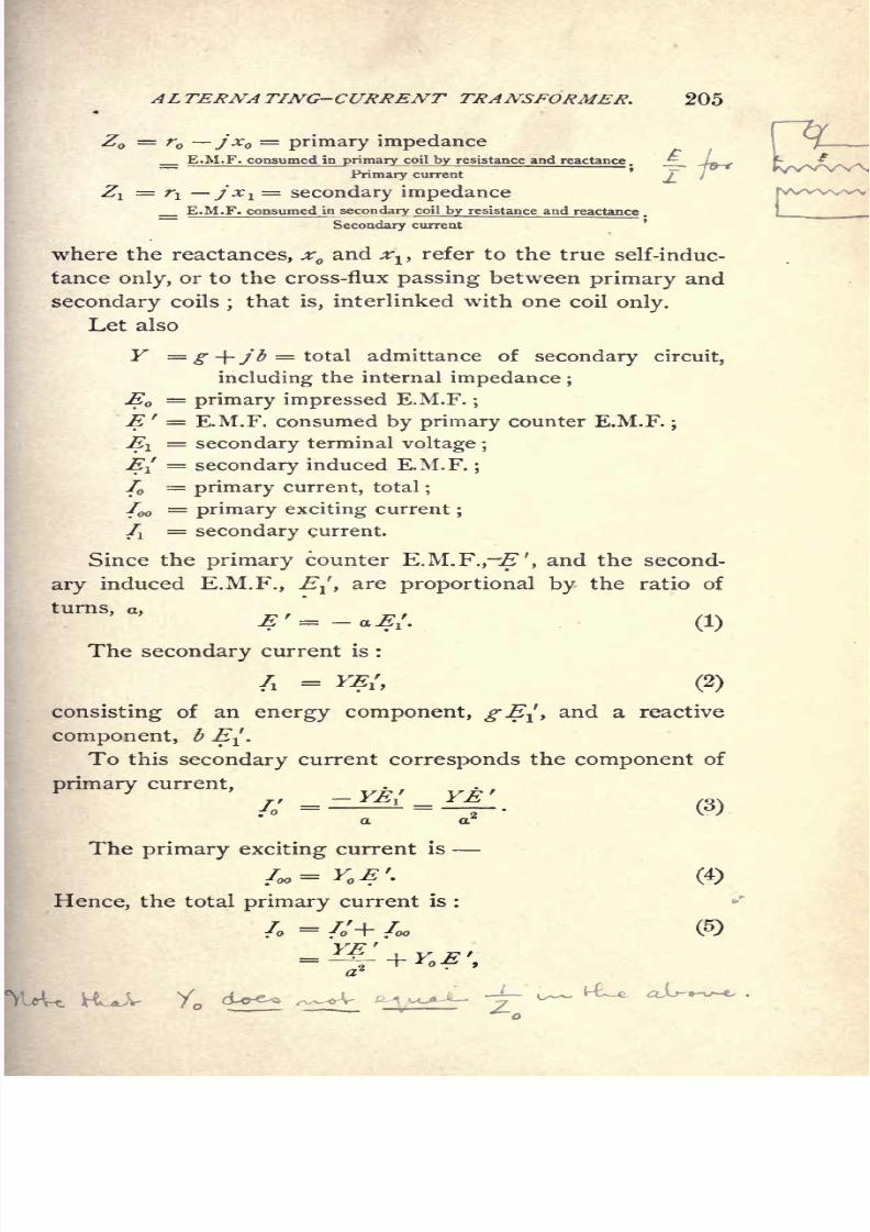
8/2/2019 Charles Steinmetz Theorycalculatio00steiiala
http://slidepdf.com/reader/full/charles-steinmetz-theorycalculatio00steiiala 231/557
rw^ww
ALTERNATING-CURRENT TRANSFORMER. 205
Z = r jx =primary impedance 7.
E.M.F. consumed in primary coil by resistance and reactance. ^ -n-f'" '
j**/\.
Primary current~
/
Z = r jx 1=
secondary impedance__ E.M.F. consumed in secondary coil by resistance and reactance .
Secondary current
where the reactances, x and ^ ,refer to the true self-induc-
tance only, or to the cross-flux passing between primary and
secondary coils;that is, interlinked with one coil only.
Let also
Y = g -\-jb- total admittance of secondary circuit,
including the internal impedance ;
E =primary impressed E.M.F.
;
E ' = E.M.F. consumed by primary counter E.M.F.;
i=
secondary terminal voltage ;
EI
=secondary
induced E.M.F.;
I = primary current, total;
/oo=
primary exciting current;
/i=
secondary current.
Since the primary counter E.M.F.,-"', and the second-
ary induced E.M.F., E^, are proportional by the ratio of
turns, a,
E ' = a E{. (1)
The secondary current is :
/i= **/, (2)
consisting of an energy component, gE^, and a reactive
component, b E^.
To this secondary current corresponds the component of
primary current,7o
=
~a a*
The primary exciting current is
I>=YO E>. (4)
Hence, the total primary current is :

8/2/2019 Charles Steinmetz Theorycalculatio00steiiala
http://slidepdf.com/reader/full/charles-steinmetz-theorycalculatio00steiiala 232/557
206 ALTERNA TING-CURRENT PHENOMENA.
(6)
The E.M.F. consumed in the secondary coil by the
internal impedance isZ-J^.
The E.M.F. induced in the secondary coil by the mag-
netic flux is EI.
Therefore, the secondary terminal voltage is
or, substituting (2),we have
,=
,' {I- Z,Y} (7)
The E.M.F. consumed in the primary coil by the inter-
nal impedance is Z I .
The E.M.F. consumed in the primary coil by the counter
E.M.F. is E'.
Therefore, the primary impressed E.M.F. is
E = E' + Z S,
or, substituting (6),
(8)\/
136. We thus have,
primary E.M.F., E = - aE{j
1 + Z Y + ^Z J
, (8)
secondary E.M.F., E^ = E{ {1 - Z
l Y}, (7)
primary current, I = -{Y+a*Y }, (6)
secondary current, /i= YE
l
'
t (2)
as functions of the secondary induced E.M.F., EJ, as pa-
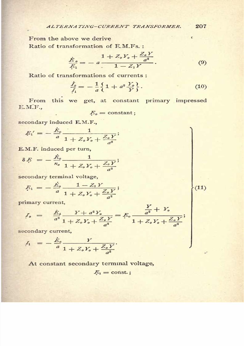
8/2/2019 Charles Steinmetz Theorycalculatio00steiiala
http://slidepdf.com/reader/full/charles-steinmetz-theorycalculatio00steiiala 233/557
ALTERNATING-CURRENT TRANSFORMER. 207
From the above we derive
Ratio of transformation of E.M.Fs. :
. 1-Z.K
Ratio of transformations of currents :
(10)
From this we get, at constant primary impressed
E.M.F.,
E = constant;
secondary induced E.M.F.,
E.M.F. induced per turn,
E 1
n-\
\ 7 y \
secondary terminal voltage,
primary current,^
4- Y,
.
EA Y+a*Y _ w ^^y
secondary current,
Y
At constant secondary terminal voltage,
-fi
1
!= const.
;

8/2/2019 Charles Steinmetz Theorycalculatio00steiiala
http://slidepdf.com/reader/full/charles-steinmetz-theorycalculatio00steiiala 234/557
208 AL TERNA TING-CURRENT PHENOMENA.
secondary induced E.M.F.,
F1 - l
1-^F'E.M.F. induced per turn,
^1-Z.F'primary impressed E.M.F.,
primary current,
/
secondary current,
136. Some interesting conclusions can be drawn from
these equations.
The apparent impedance of the total transformer is
(14)
Substituting now, = V, the total secondary admit-
tance, reduced to the primary circuit by the ratio of turns,
it is
Y -\-Y' is the total admittance of a divided circuit with
the exciting current, of admittance Y,and the secondary
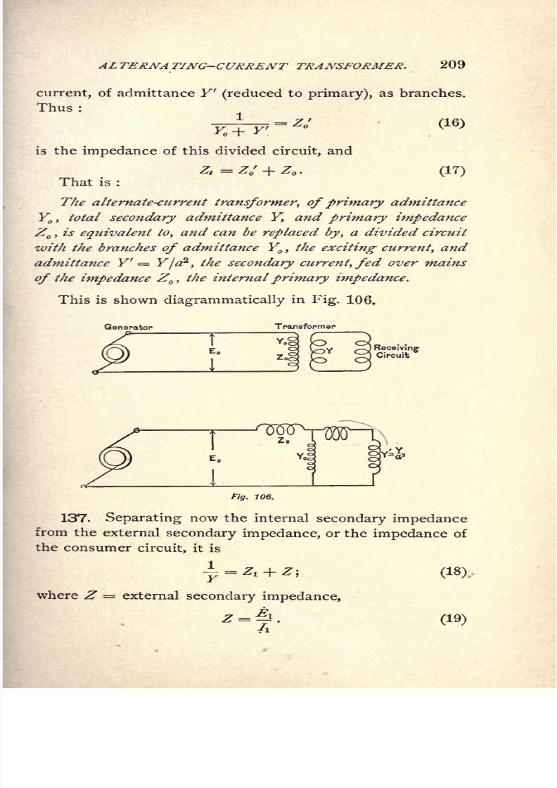
8/2/2019 Charles Steinmetz Theorycalculatio00steiiala
http://slidepdf.com/reader/full/charles-steinmetz-theorycalculatio00steiiala 235/557
ALTERNA TING-CURRENT TRANSFORMER. 209
current, of admittance Y 1
(reducedto
primary),
as branches.
Thus :
is the impedance of this divided circuit, and
That is :
(17)
The alternate-current transformer, ofprimary admittance
Y,
total secondary admittance Y, and primary impedance
Z,is equivalent to, and can be replaced by, a divided circuit
with the branches of admittance Y,the exciting current, and
admittance Y' = Y/a2
,the secondary current, fed over mains
of the impedance Z ,the internal primary impedance.
This is shown diagrammatically in Fig. 106.
Yog
z
Fig. 106.
137. Separating now the internal secondary impedance
from the external secondary impedance, or the impedance of
the consumer circuit, it is
4-.+ *! (18)
where Z = external secondary impedance,
(19)
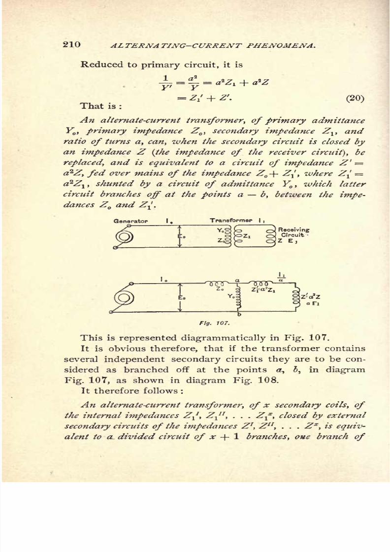
8/2/2019 Charles Steinmetz Theorycalculatio00steiiala
http://slidepdf.com/reader/full/charles-steinmetz-theorycalculatio00steiiala 236/557
210 ALTERNATING-CURRENT PHENOMENA.
Reduced to
primarycircuit, it is
= Z/ + Z7
.
(20)
That is :
An alternate-current transformer, of primary admittance
Y, primary impedance Z
, secondary impedance Zv and
ratio of turns a, can, when the secondary circuit is closed by
an impedance Z (the impedance of the receiver circuit), be
replaced, and is equivalent to a circtiit of impedance Z' =
a?Z, fed over mains of the impedance Z -\- Z^, where Z^ =a2Z
ltshunted by a circuit of admittance Y
,which latter
circuit branches off at the points a b, between the impe-
dances Z and Z-.
Generator I,Transformer I
Fig. 107.
This is represented diagrammatically in Fig. 107.
It is obvious therefore, that if the transformer contains
several independent secondary circuits they are to be con-
sidered as branched off at the points a, i, in diagram
Fig. 107, as shown in diagram Fig. 108.
It therefore follows :
An alternate-current transformer, of x secondary coils, of
the internal impedances Z^, Z^1
,. . . Z-f, closed by external
secondary circuits of the impedances Z1, Zn,
. . .
Zx
, is equiv-
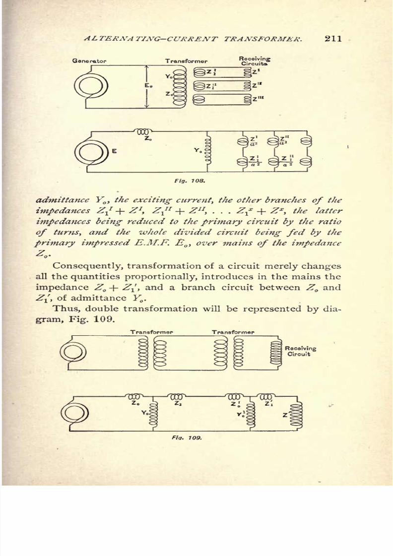
8/2/2019 Charles Steinmetz Theorycalculatio00steiiala
http://slidepdf.com/reader/full/charles-steinmetz-theorycalculatio00steiiala 237/557
ALTERNA TING-CURRENT TRANSFORMER.
Generator Transformer
211
Fig. 108.
admittance Y0)the exciting current, the other branches of the
impedances ZJ + Z7
,
ZJ
1
+ Zn
,. . .
2f + Zx
,
the latter
impedances being reduced to the primary circuit by the ratio
of turns, and the whole divided circuit being fed by the
primary impressed E.M.F., over -mains of the impedance
Z -
Consequently, transformation of a circuit merely changes
all the quantities proportionally, introduces in the mains the
impedance Z + Z^, and a branch circuit between Z and
Z^, of admittance Y .
Thus, double transformation will be represented by dia-
gram, Fig. 109.

8/2/2019 Charles Steinmetz Theorycalculatio00steiiala
http://slidepdf.com/reader/full/charles-steinmetz-theorycalculatio00steiiala 238/557
212 AL TERNA TING-CURRENT PHENOMENA .
With this the discussion of the alternate-current trans-
former ends, by becoming identical with that of a divided
circuit containing resistances and reactances.
Such circuits have explicitly been discussed in Chapter
VIII., and the results derived there are now directly appli-
cable to the transformer, giving the variation and the con-
trol of secondary terminal voltage, resonance phenomena, etc.
Thus, for instance, if Z/ = Z ,and the transformer con-
tains an additional secondary coil, constantly closed by a
condenser reactance of such size that this auxiliary circuit,
together with the exciting circuit, gives the reactance x,
.
with a non-inductive secondary circuit Z^= rv we get the
condition of transformation from constant primary potential
to constant secondary current, and inversely, as previously
discussed.
Non-inductive Secondary Circuit.
138. In a non-inductive secondary circuit, the external
secondary impedance is,
or, reduced to
primarycircuit,
Assuming the secondary impedance, reduced to primary
circuit, as equal to the primary impedance,
* is>
Y
'
i r
Substituting these values in Equations (9), (10),and (13),
we have
Ratio of E.M.Fs. :
(r jx }
4- ra jx
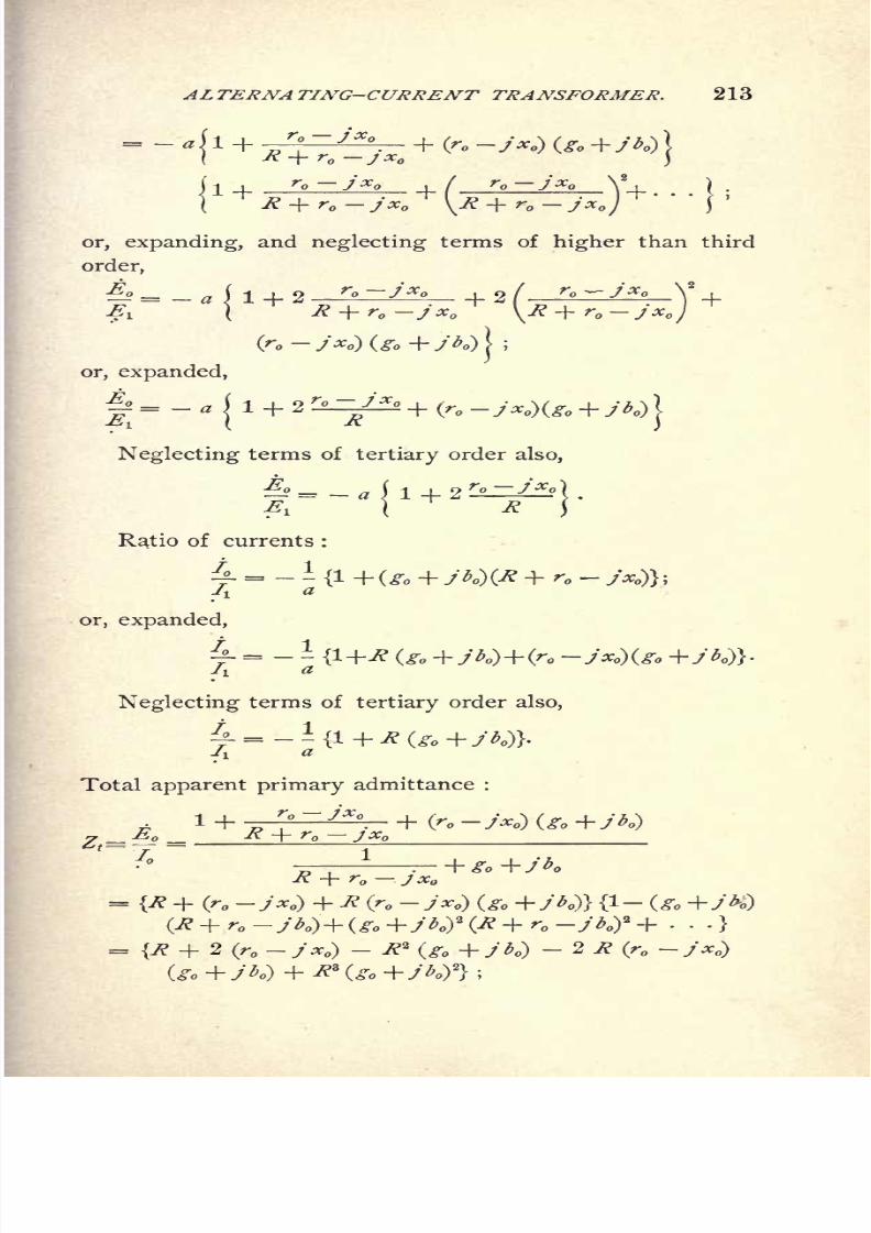
8/2/2019 Charles Steinmetz Theorycalculatio00steiiala
http://slidepdf.com/reader/full/charles-steinmetz-theorycalculatio00steiiala 239/557
ALTERNATING-CURRENT TRANSFORMER. 213
+r -jx f r -jx
Y| . . .\ .
R + r jx \R + rn /#
or, expanding, and neglecting terms of higher than third
order,
jx^
or, expanded,
J|=-
1
1 + 2r
^'^ + (r, -y^)(.%
Neglecting terms of tertiary order also,
t
Ratio of currents :
^-= - -
/I^
or, expanded,
~=--/! a
Neglecting terms of tertiary order also,
Totalapparent primary
admittance :
R + r jx
(r -jx } + R (r-
= {R + 2 (r - y x } - &(go +jb }
-2 R (r - Jx )
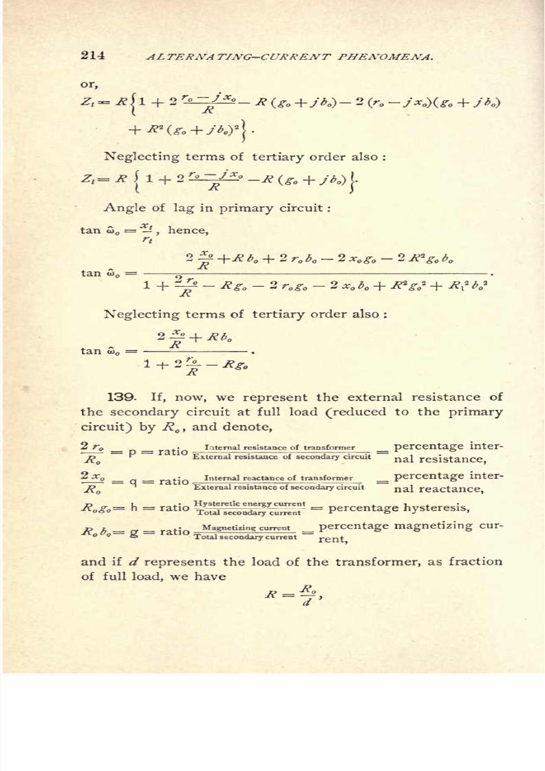
8/2/2019 Charles Steinmetz Theorycalculatio00steiiala
http://slidepdf.com/reader/full/charles-steinmetz-theorycalculatio00steiiala 240/557
214 ALTERNATING-CURRENT PHENOMENA.
or,
b }- 2 (r -Jx }(
Neglecting terms of tertiary order also :
Zt=R
Angle of lag in primary circuit :
tan S> = ^, hence,
rt
2^+Rb + 2r b -2 Xogo -2tan S> = a
Neglecting terms of tertiary order also :
'R
139. If, now, we represent the external resistance of
the secondary circuit at full load (reduced to the primary
circuit) by R ,and denote,
2 r _ _ . Internal resistance of transformer _ percentage
R~
External resistance of secondary circuit~
na^ resistance,
2 X _ __ratjQ
Internal reactance of transformer _ percentage
J'
External resistance of secondary circuit nal reactance
X*.- h - ratio - percentage hysteresis,
,, , ,. Magnetizing current percentage magnetizing cur-
KO o= g = -10Totalsecondarycurrent
=rent
^
and if d represents the load of the transformer, as fraction
of full load, we have

8/2/2019 Charles Steinmetz Theorycalculatio00steiiala
http://slidepdf.com/reader/full/charles-steinmetz-theorycalculatio00steiiala 241/557
ALTERNATING-CURRENT TRANSFORMER. 215
and,
**.-.a
Substituting these values we get, as the equations of the
transformer on non-inductive load,
Ratio of E.M.Fs. :
or, eliminating imaginary quantities,
H"-"^)
Ratio of currents :
+ (h +>
d 2 f
.^r, eliminating imaginary quantities,
1f
a \
i i
hi

8/2/2019 Charles Steinmetz Theorycalculatio00steiiala
http://slidepdf.com/reader/full/charles-steinmetz-theorycalculatio00steiiala 242/557
216 ALTERNATING-CURRENT PHENOMENA.
Total
apparent primary impedance
:
Z, =
or, eliminating imaginary quantities,
Angle of lag in primary circuit :
That is,
An alternate-current transformer, feeding into a non-induc-
tive secondary circuit, is represented by the constants :
R =secondary external resistance at full load
;
p=
percentage resistance;
q=
percentage reactance;
h =percentage hysteresis ;
g =percentage magnetizing current
;
d =secondary percentage load.
All these qualities being considered as reduced to the primarycircuit the the ratio turns, a2
.

8/2/2019 Charles Steinmetz Theorycalculatio00steiiala
http://slidepdf.com/reader/full/charles-steinmetz-theorycalculatio00steiiala 243/557
ALTERNATING-CURRENT TRANSFORMER. 217
140. As an instance, a transformer of the following
constants may be given :
e =1,000;a = 10
;
= 120;
p= .02
q= .06
;
h = .02;
g = .04.
Substituting these values, gives :
100=
V(i.oou +.02
</)
2
+ (.0002 +.06
<ty
*-^--.1 ii V/Y 1.0014 + Y + (
-\\ d
J \ d.0002 .
- -.0004-
tan w,^-
1.9972 +.
110. Load
8/2/2019 Charles Steinmetz Theorycalculatio00steiiala
http://slidepdf.com/reader/full/charles-steinmetz-theorycalculatio00steiiala 244/557
218 ALTERNATING-CURKENT PHENOMENA.
In diagram Fig. 110 are shown, for the values from
d = to d= 1.5, with the secondary current ix
as abscis-
sae, the values :
secondary terminal voltage, in volts,
secondary drop of voltage, in per cent,
primary current, in amps,
excess of primary current over proportionality with
secondary, in per cent,
primary angle of lag.
The power-factor of the transformer, cos w,
is .45 at
open secondary circuit, and is above .99 from 25 amperes,
upwards, with a maximum of .995 at full load.

8/2/2019 Charles Steinmetz Theorycalculatio00steiiala
http://slidepdf.com/reader/full/charles-steinmetz-theorycalculatio00steiiala 245/557
ALTERNATING-CURRENT TRANSFORMER. 219
CHAPTER XV.
THE GENERAL ALTERNATING-CURRENT TRANSFORMER ORFREQUENCY CONVERTER.
141. The simplest alternating-current apparatus is the
alternating-current transformer. It consists of a magnetic-
circuit, interlinked with two electric circuits or sets of
electric circuits. The one, the primary circuit, is excited
by an impressed E.M.F., while in the other, the secondary
circuit, an E.M.F. is induced. Thus, in the primary circuit,
power is consumed, in the secondary circuit a correspond-
ing amount of power produced ;or in other words, power
is transferred through space, from primary to secondary
circuit. This transfer of power finds its mechanical equiv-
alent in a repulsive thrust acting between primary and
secondary. Thus, if the secondary coil is not held rigidly
as in the stationary transformer, it will be repelled and
move away from the primary. This mechanical effect is
made use of in the induction motor, which represents a
transformer whose secondary is mounted movably with re-
gard to the primary in such a way that, while set in rota-
tion, it still remains in the primary field of force. The
condition that the secondary circuit, while revolving with
regard to the primary, does not leave the primary field of
magnetic force, requires that this field is not undirectional,
but that an active field exists in every direction. One way
of producing such a magnetic field is by exciting different
primary circuits angularly displaced in space with each
other by currents of different phase. Another way is to
excite the primary field in one direction only, and get the
cross magnetization, or the angularly displaced magneticfield, by the reaction of the current.

8/2/2019 Charles Steinmetz Theorycalculatio00steiiala
http://slidepdf.com/reader/full/charles-steinmetz-theorycalculatio00steiiala 246/557
220 ALTERNATING-CURRENT PHENOMENA.
We see, consequently, that the stationary transformer
and the induction motor are merely different applications
of the same apparatus, comprising a magnetic circuit in-
terlinked with two electric circuits. Such an apparatus
can properly be called a "general alternating-current trans-
former" The equations of the stationary transformer and
those of the induction motor are merely specializations of
the general alternating-current transformerequations.
Quantitatively the main differences between induction
motor and stationary transformer are those produced by
the air-gap between primary and secondary, which is re-
quired to give the secondary mechanical movability. This
air-gap greatly increases the magnetizing current over that
in the closed magnetic circuit transformer, and requires
an ironclad construction of primary and secondary to keepthe magnetizing current within reasonable limits. An iron-
clad construction again greatly increases the self-induction
of primary and secondary circuit. Thus the induction
motor is a transformer of large magnetizing current and
large self-induction; that is, comparatively large primary
exciting susceptance and large reactance.
The general alternating-current transformer transforms
between electrical and mechanical power, and changes not
only E.M.Fs. and currents, but frequencies also, and maytherefore be called a "frequency converter." Obviously,
it also may change the number of phases.
142. Besides the magnetic flux interlinked with both
primary and secondary electric circuit, a magnetic cross-
flux passes in the transformer between primary and second-
ary, surrounding one coil only, without being interlinked
with the other. This magnetic cross-flux is proportional to
the current flowing in the electric circuit, and constitutes
what is called the self-induction of the transformer. As
seen, as self-induction of a transformer circuit, not the total
fluxproduced by
and interlinked with this circuit is under-
stood, but only that usually small part of the flux

8/2/2019 Charles Steinmetz Theorycalculatio00steiiala
http://slidepdf.com/reader/full/charles-steinmetz-theorycalculatio00steiiala 247/557
ALTERNA TING-CURRENT TRANSFORMER. 221
which surrounds the one circuit without interlinking with
the other, and is thus produced by the M.M.F. of one
circuit only.
143. The mutual magnetic flux of the transformer is
produced by the resultant M.M.F. of both electric circuits.
It is determined by the counter E.M.F., the number of
turns, and the frequency of the electric circuit, by the.
equation:
Where E = effective E.M.F.
JV= frequency.
n = number of turns.
< == maximum magnetic flux.
The M.M.F. producing this flux, or the resultant M.M.F.
of primary and secondary circuit, is determined by shape
and magnetic characteristic of the material composing the
magnetic circuit, and by the magnetic induction. At open
secondary circuit, this M.M.F. is the M.M.F. of the primary
current, which in this case is called the exciting current,
and consists of an energy component, the magnetic energy
current, and a reactive component, the magnetizing current.
144. In the general alternating-current transformer,
where the secondary is movable with regard to the primary,
the rate of cutting of the secondary electric circuit with the
mutual magnetic flux is different from that of the primary.
Thus, the frequencies of both circuits are different, and the
induced E.M.Fs. are not proportional to the number of
turns as in the stationary transformer, but to the product
of number of turns into frequency.
145. Let, in a general alternating-current transformer :
* = ratio iS^ frequency, or slip ;
thus, if
N'=primary frequency, or frequency of impressed E.M.F.,
s JV= secondary frequency ;
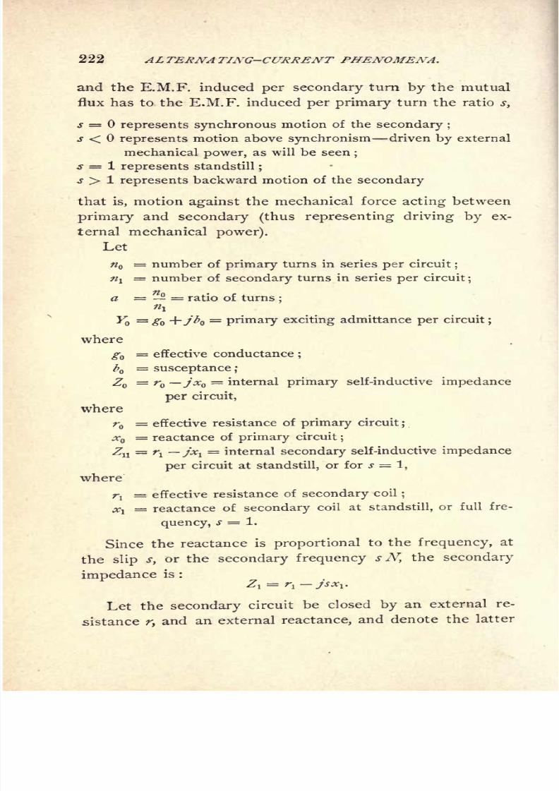
8/2/2019 Charles Steinmetz Theorycalculatio00steiiala
http://slidepdf.com/reader/full/charles-steinmetz-theorycalculatio00steiiala 248/557
222 ALTERNATING-CURRENT PHENOMENA.
and the E.M.F. induced per secondary turn by the mutual
flux has to the E.M.F. induced per primary turn the ratio s,
s = represents synchronous motion of the secondary ;
s < represents motion above synchronism driven by external
mechanical power, as will be seen;
s = 1 represents standstill;
s > 1 represents backward motion of the secondary
that is, motion against the mechanical force acting between
primary and secondary (thus representing driving by ex-
ternal mechanical power).
Let
= number of primary turns in series per circuit;
/?!= number of secondary turns in series per circuit
;
a = = ratio of turns;
i
Y ="0 H~./A)=
primary exciting admittance per circuit;
where
gQ= effective conductance
;
b = susceptance ;
Z = r jx = internal primary self-inductive impedance
per circuit,
where
r = effective resistance of primary circuit;
jr = reactance of primary circuit;
Zu = TI jxv= internal secondary self-inductive impedance
per circuit at standstill, or for s = 1,
where
rj= effective resistance of secondary coil
;
Xl reactance of secondary coil at standstill, or full fre-
quency, s = 1.
Since the reactance is proportional to the frequency, at
the slip s, or the secondary frequency s N, the secondary
impedance is :
Zl= r
1 -jsxl.
Letthe
secondarycircuit be closed
byan external re-
sistance r, and an external reactance, and denote the latter
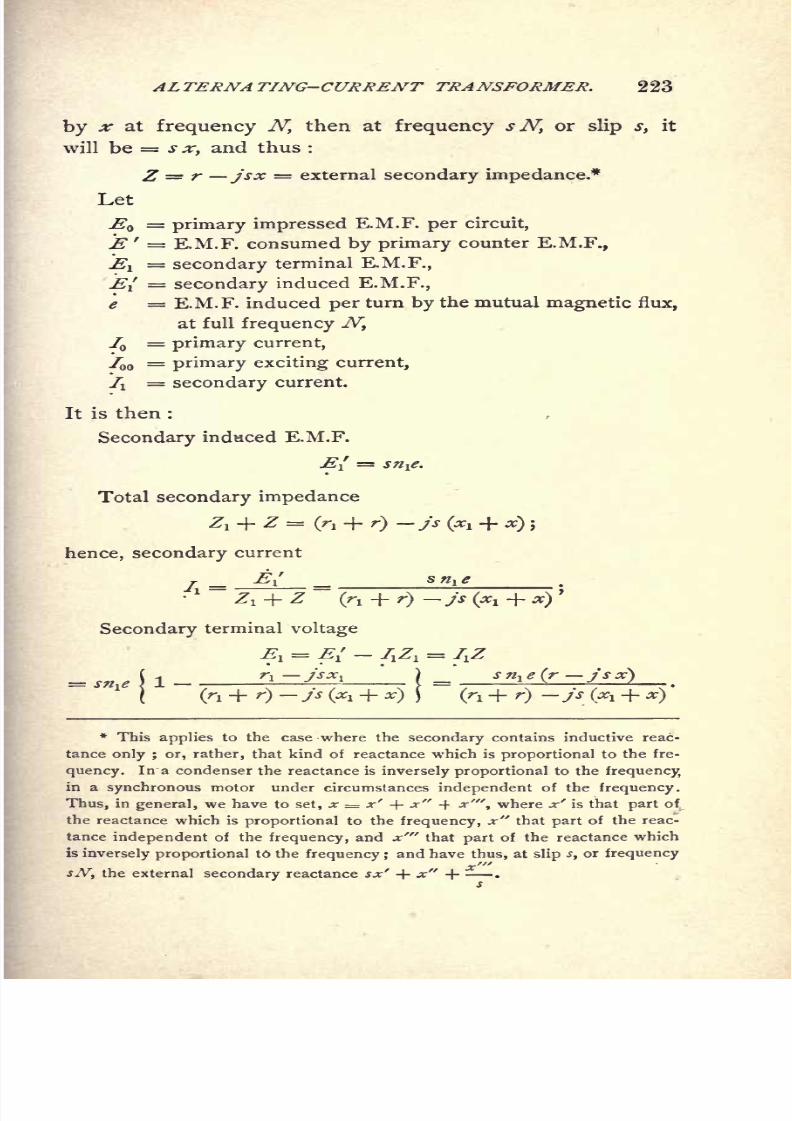
8/2/2019 Charles Steinmetz Theorycalculatio00steiiala
http://slidepdf.com/reader/full/charles-steinmetz-theorycalculatio00steiiala 249/557
ALTERNATING-CURRENT TRANSFORMER, 223
by x at frequency N, then at frequency s N, or slip s, it
will be = s x, and thus :
Z = r jsx = external secondary impedance.*
Let
=primary impressed E.M.F. per circuit,
E ' = E.M.F. consumed by primary counter E.M.F.,
1= secondary terminal E.M.F.,
EI = secondary induced E.M.F.,e = E.M.F. induced per turn by the mutual magnetic flux,
at full frequency JY,
IQ=
primary current,
^ = primary exciting current,
7i= secondary current.
It is then :
Secondary induced E.M.F.
EI =sn^e.
Total secondary impedance
Z, + Z= (r, + r)
hence, secondary current
Secondary terminal voltage
* This applies to the case where the secondary contains inductive reac-
tance only ; or, rather, that kind of reactance which is proportional to the fre-
quency. In a condenser the reactance is inversely proportional to the frequency,
in a synchronous motor under circumstances independent of the frequency.
Thus, in general, we have to set, x = x' + x" -\ x"\ where x' is that part of
the reactance which is proportional to the frequency, x" that part of the reac-
tance independent of the frequency, and x'" that part of the reactance which
is inversely proportional t6 the frequency ;and have thus, at slip s, or frequency
sN, the external secondary reactance sx' + x" -f- .
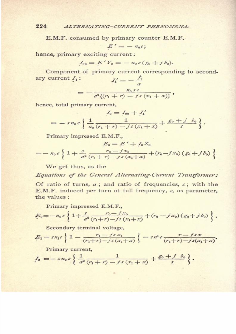
8/2/2019 Charles Steinmetz Theorycalculatio00steiiala
http://slidepdf.com/reader/full/charles-steinmetz-theorycalculatio00steiiala 250/557
224 ALTERNA TING-CURRENT PHENOMENA,
E.M.F. consumed by primary counter E.M.F.
'= -<>';
hence, primary exciting current :
700 = E' YQ
= e (g + /<))
Component of primary current corresponding to second-
ary current 7X
:
hence, total primary current,
//
1
Primary impressed E.M.F.,
We get thus, as the
Equations of the General Alternating-Current Transformer:
Of ratio of turns, a;and ratio of frequencies, s
;with the
E.M.F. induced per turn at full frequency, e, as parameter,
the values :
Primary impressed E.M.F.,
Secondary terminal voltage,
Primary current,
\ 1

8/2/2019 Charles Steinmetz Theorycalculatio00steiiala
http://slidepdf.com/reader/full/charles-steinmetz-theorycalculatio00steiiala 251/557
ALTERNATING-CURRENT TRANSFORMER. 225
Secondary current,
II =7 -7-
Therefrom, we get :
Ratio of currents,
Ratio of E.M.Fs.,
Total apparent primary impedance,
, , . x" . x'"where
xx-\---
\-
s s2
in the general secondary circuit as discussed in foot-note,
page 221.
Substituting in these equations :
*-l,gives the
General Equations of the Stationary Alternating-Current
Transformer :
z*+z\ z, + z
'* = -<\
.,;,* +IU-(Zj + Z)
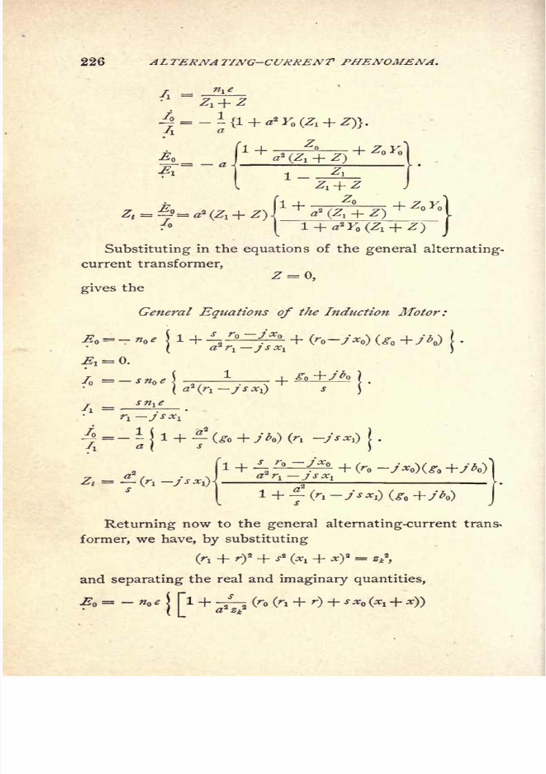
8/2/2019 Charles Steinmetz Theorycalculatio00steiiala
http://slidepdf.com/reader/full/charles-steinmetz-theorycalculatio00steiiala 252/557
ALTERNA TING-CURRENT PHENOMENA.
r n t e
yi
= Z, + Z
/! a
P f1 + *f7\^ + Z' Y*
^o_= _ a }a (Z-j + 2}
& I- Z*
( Z, + Z
1+2// x+^oKo]2
(Zj + Z) _I
l + ^Fo^ + Z)J
Substituting in the equations of the general alternating-
current transformer,
Z = 0,
gives the
General Eqtiations of tJie Induction Motor:
a'r^-jsx^
^ = 0.
1i ^o +y^o7 = _ s f
] -T, . .
1
(>-! y**or j,^A =
5
"^:
~ + (ro y^o)(^b +/
^i JSXi
Returning now to the general alternating-current trans^
former, we have, by substituting
(ri + r? + ^2
(*i + *)2 =
**f
,
and separating the real and imaginary quantities,
-- (r (r, + r)+sx9 (Xl + x))2

8/2/2019 Charles Steinmetz Theorycalculatio00steiiala
http://slidepdf.com/reader/full/charles-steinmetz-theorycalculatio00steiiala 253/557
ALTERNATING-CURRENT TRANSFORMER, 227
Neglecting the exciting current, or rather considering
it as a separate and independent shunt circuit outside of
the transformer, as can approximately be done, and assum-
ing the primary impedance reduced to the secondary circuit
as equal to the secondary impedance,
Substituting this in the equations of the general trans-
former, we get,
,=- e\ I + -
fr fa + r)
146. The true power is, in symbolic representation (see
Chapter XII.) :
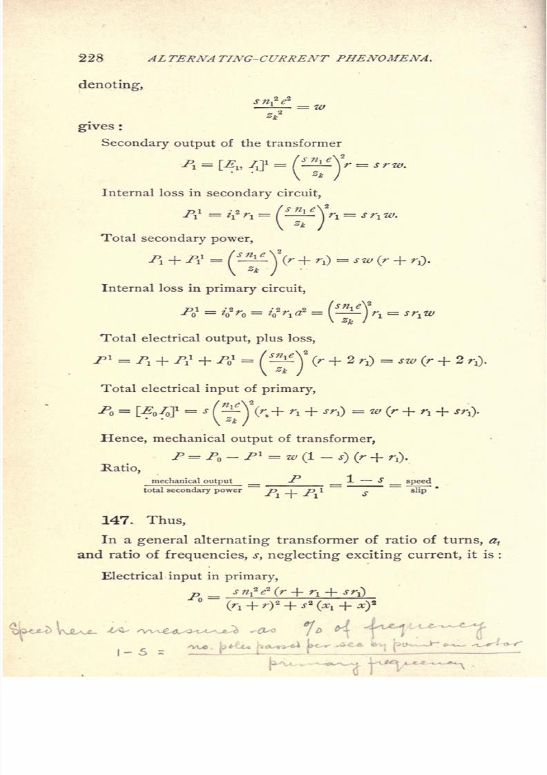
8/2/2019 Charles Steinmetz Theorycalculatio00steiiala
http://slidepdf.com/reader/full/charles-steinmetz-theorycalculatio00steiiala 254/557
228 ALTERNATING-CURRENT PHENOMENA.
denoting,
safe*
-7F= W
gives :
Secondary output of the transformer
Internal loss in
secondary circuit,
m -2 t s n\ ^\2
-Pi=
'i
2 n =( }
V ** /
Total secondary power,
**
Internal loss in primary circuit,
ri -9 -9o^o = V'o = 4 rt<r
Total electrical output, plus loss,
2
Total electrical input of primary,
Hence, mechanical output of transformer,
P=P-P* = w(l-s)(rE.atio,
mechanical output _P 1 S _ speed
total secondary power P -\- P l
147. Thus,
In a general alternating transformer of ratio of turns, a,
and ratio of frequencies, s, neglecting exciting current, it is :
Electrical input in primary,
P
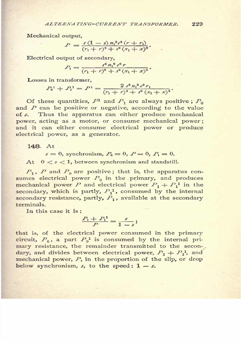
8/2/2019 Charles Steinmetz Theorycalculatio00steiiala
http://slidepdf.com/reader/full/charles-steinmetz-theorycalculatio00steiiala 255/557
ALTERNATING-CURRENT TRANSFORMER. 229
Mechanical output,
P - jg-j)iV(r+rO '
Electrical output of secondary,
Losses in transformer,
Of these quantities, P1 and Plare always positive ;
PQ
and P can be positive or negative, according to the value
of s. Thus the apparatus can either produce mechanical
power, acting as a motor, or consume mechanical power;
and it can either consume electrical power or produce
electrical power, as a generator.
148. At
s = 0, synchronism, PQ=
0, P = 0, Pl= 0.
At < s < 1, between synchronism and standstill.
Pl ,P and PQ are positive ;
that is, the apparatus con-
sumes electrical power PQin the primary, and produces
mechanical power P and electrical power Pl -j- P^ in the
secondary, which is partly, P-^, consumed by the internal
secondary resistance, partly, Pl ,available at the secondary
terminals.
In this case it is :
Pi + ^i
1
_ J
P ~l-s>
that is, of the electrical power consumed in the primary
circuit, P ,a part P^ is consumed by the internal pri-
mary resistance, the remainder transmitted to the secon-
dary, and divides between electrical power, P1 + P^1,and
mechanical power, P, in the proportion of the slip,or drop
below synchronism, s, to the speed : 1 s.

8/2/2019 Charles Steinmetz Theorycalculatio00steiiala
http://slidepdf.com/reader/full/charles-steinmetz-theorycalculatio00steiiala 256/557
230 ALTERNATING-CURRENT PHENOMENA.
In this range, the apparatus is a motor.
At s > 1; or, backwards driving,
P < 0, or negative ;that is, the apparatus requires mechanical
power for driving.
It is then : P - A 1 - A 1 < PI ;
that is : the secondary electrical power is produced partly
by
the primary electrical power,partly by
the mechanical
power, and the apparatus acts simultaneously as trans-
former and as alternating-current generator, with the sec-
ondary as armature.
The ratio of mechanical input to electrical input is the
ratio of speed to synchronism.
In this case, the secondary frequency is higher than the
primary.
At s < 0, beyond synchronism,
P < ;that is, the apparatus has to be driven by mechanical
power.
/o<0; that is, the primary circuit produces electrical power
from the mechanical input.
At r+r! + srj. = 0, or, s < ^^J
;
rt
the electrical power produced in the primary becomes less
than required to cover the losses of power, and /> becomes
positive again.
We have thus :
K-flr\
consumes mechanical and primary electric power ; produces
secondary electric power.
-r-^ < s <
?i
consumes mechanical, and produces electrical power in
primary and in secondary circuit.

8/2/2019 Charles Steinmetz Theorycalculatio00steiiala
http://slidepdf.com/reader/full/charles-steinmetz-theorycalculatio00steiiala 257/557
ALTERNATING-CURRENT TRANSFORMER. 231
consumes primary electric power, and produces mechanical
and secondary electrical power.
consumes mechanical and primary electrical power ; pro-
duces secondary electrical power.
T
GENERAL ALTERNATE CURRENT TRANSFORMER
A
648Fig
H
149. As an instance, in Fig. Ill are plotted, with the
slip s as abscissae, the values of :
Secondary electrical output as Curve I.;
Total internal loss as Curve II.;
Mechanical output as Curve III.;
Primary electrical input as Curve IV.;
for the values :
n,e = 100.0;
r = A;
r 4.i x = .3;
8/2/2019 Charles Steinmetz Theorycalculatio00steiiala
http://slidepdf.com/reader/full/charles-steinmetz-theorycalculatio00steiiala 258/557
232 ALTERNATING-CURRENT PHENOMENA.
hence,
p= 16,000 ^
2
.
pl , P i _ 8,000 j.""" l
-i, j"
?
_ 4,000 s + (5 + J) .~1 I
2'
p = 20,000 s (1-
j)
150. Since the most common practical application of
the general alternating current transformer is that of fre-
quency converter, that is to change from one frequency to
another, either with or without change of the number of
phases, the following characteristic curves of this apparatus
are of great interest.
1. The regulation curve;that is, the change of second-
ary terminal voltage as function of the load at constant im-
pressed primary voltage.
2. The compounding curve;that is, the change of pri-
mary impressed voltage required to maintain constant sec-
ondary terminal voltage.
In this case the impressed frequency and the speed are
constant, and consequently the secondary frequency. Gen-
erally the frequency converter is used to change from a low
frequency, as 25 cycles, to a higher frequency, as 62.5
cycles, and is then driven backward, that is, against its
torque, by mechanical power. Mostly a synchronous motor
is
employed,connected to the
primary mains,which
byover-excitation compensates also for the lagging current of
the frequency converter.
Let,
Y = g +j& =primary exciting admittance per circuit
of the frequency converter.
Z^= r
t jx^ internal self inductive impedance per
secondary circuit, at the secondary frequency.

8/2/2019 Charles Steinmetz Theorycalculatio00steiiala
http://slidepdf.com/reader/full/charles-steinmetz-theorycalculatio00steiiala 259/557
ALTERNATING-CURRENT TRANSFORMER. 233
Z^= r jx^
= internal self inductive impedance per
primary circuit at the primary frequency.a = ratio of secondary to primary turns per circuit.
b = ratio of number of secondary to number of primary
circuits.
c = ratio of secondary to primary frequencies.
Let,
e = induced E.M.F. per secondary circuit at secondary
frequency.
Z = r jx = external impedance per secondary circuit
at secondary frequency, that is load on secondary system,
where x for noninductive lead.
We then have,
total secondary impedance,
Z + Z1
=(r-^rl
)-j(x + x1)
secondary current,
where,
r+ r. x + Xl
(r + 0>2 + (* + ^)
2
(r +^i)2 + (* +
secondary terminal voltage,
Ei = IiZ = e ^4-T
e(r jx) (at
where,
primaryinduced E.M.F.
percircuit,
primary load current per circuit,
71 =abli
= abe (a{
primary exciting current per circuit,

8/2/2019 Charles Steinmetz Theorycalculatio00steiiala
http://slidepdf.com/reader/full/charles-steinmetz-theorycalculatio00steiiala 260/557
234 ALTERNATING-CURRENT PHENOMENA.
thus, total primary current,
7 = 71
+ /oo
= e(fi
where,
<.= **+ <.=**+!
primary terminal voltage :
where,
d - re x d -re -xac
or absolute,
e = e vX2 + 42
. =e -
V^2 + 4
substituting this value of e in the preceding equations,
gives, as function of the primary impressed E.M.F., e :
secondary current,
7 = >
absolu 7 = viV4 + 4
2 v ^i2 +
secondary terminal voltage,
primary current,
, _
primary impressed E.M.F.
^ _ ^0 (4"
V4
secondary output,
gl
^+

8/2/2019 Charles Steinmetz Theorycalculatio00steiiala
http://slidepdf.com/reader/full/charles-steinmetz-theorycalculatio00steiiala 261/557
AL TERNA TING-CURRENT TRANSFORMER. 235
primary electrical input,
i +Lr: oj
</ + </.*
primary apparent input, voltamperes,
<2o=
4/o
Substituting thus different values for the secondary in-
ternal impedance Z gives the regulation curve of the fre-
quency converter.
REGULATION CURVESVOLTS CONSTANT! 25 CYCLES
DARY 62.5 CYCLE QUARTER-PHASE
TDARY0
CURRENT PER PHASE, AMP.
3)
Fig. 112,
Such a curve, taken from tests of a 20"0 KW frequency
converter changing from 6300 volts 25 cycles three-phase,
to 2500 volts 62.5 cycles quarter-phase, is given in Fig.
112.

8/2/2019 Charles Steinmetz Theorycalculatio00steiiala
http://slidepdf.com/reader/full/charles-steinmetz-theorycalculatio00steiiala 262/557
236 ALTERNA TING-CURRENT PHENOMENA.
From the secondary terminal voltage,
it follows, absolute,
Fig. 113.
Substituting these values in tne above equation gives
the quantities as functions of the secondary terminal vol-
tage, that is at constant el ,
or the compounding curve.
Thecompounding
curve of the frequency converter
above mentioned is given in Fig. 113.

8/2/2019 Charles Steinmetz Theorycalculatio00steiiala
http://slidepdf.com/reader/full/charles-steinmetz-theorycalculatio00steiiala 263/557
INDUCTION MOTOR. 237
CHAPTER XVI.
INDUCTION MOTOR.
151. A specialization of the general alternating-current
transformer is the induction motor. It differs from the
stationary alternating-current transformer, which is also a
specialization of the general transformer, in so far as in the
stationary transformer only the transfer of electrical energy
from primary to secondary is used, but not the mechanical
force acting between the two, and therefore primary and
secondary coils are held rigidlyin position with regard to
each other. In the induction motor, only the mechanical
force between primary and secondary is used, but not the
transfer of electrical energy, and thus the secondary circuits
closed upon themselves. Transformer and induction motor
thus are the two limiting cases of the general alternating-
current transformer. Hence the induction motor consists
of a magnetic circuit interlinked with two electric circuits or
sets of circuits, the primary and the secondary circuit, which
are movable with regard to each other. In general a num-
ber of primary and a number of secondary circuits are used,
angularly displaced around the periphery of the motor, and
containing E.M.Fs. displaced in phase by the same angle.
This multi-circuit arrangement has the object always to
retain secondary circuits in inductive relation to primary
circuits and vice versa, in spite of their relative motion.
The result of the relative motion between primary and
secondary is, that the E.M.Fs. induced in the secondary or
the motor armature are not of the same frequency as the
E.M.Fs. impressed upon the primary, but of a frequency
which is the difference between the impressed frequency
8/2/2019 Charles Steinmetz Theorycalculatio00steiiala
http://slidepdf.com/reader/full/charles-steinmetz-theorycalculatio00steiiala 264/557
238 ALTERNATING-CURRENT PHENOMENA.
and the frequency of rotation, or equal to the "slip," that is,
the difference between synchronism and speed (in cycles).
Hence, if
N =frequency of main or primary E.M.F.,
and s =percentage slip ;
sJV =frequency of armature or secondary E.M.F.,
and (1 s)N= frequency of rotation of armature.
In its reaction upon the primary circuit, however, the
armature current is of the same frequency as the primary
current, since it is carried around mechanically, with a fre-
quency equal to the difference between its own frequency
and that of the primary. Or rather, since the reaction of
the secondary on the primary must be of primary frequency
whatever the speed of rotation the secondary frequencyis always such as to give at the existing speed of rotation a
reaction of primary frequency.
152. Let the primary system consist of / equal circuits,
displaced angulary in space by 1 // of a period, that is,
1 // of the width of two poles, and excited by / E.M.Fs.
displaced in phase by 1 // of a period ; that is, in other
words, let the field circuits consist of a symmetrical / -phase
system. Analogously, let the armature or secondary circuits
consist of a symmetrical /rphase system.
Let
n = number of primary turns per circuit or phase ;
a= number of
secondary
turns per circuit or phase ;
a = -^ = ratio of total primary turns to total secondary turnsn\P\
or ratio of transformation.
Since the number of secondary circuits and number of
turns of the secondary circuits, in the induction motor as
in the stationary transformer is entirely unessential, it is
preferable to reduce all secondary quantities to the primarythe ratio of a thus

8/2/2019 Charles Steinmetz Theorycalculatio00steiiala
http://slidepdf.com/reader/full/charles-steinmetz-theorycalculatio00steiiala 265/557
INDUCTION MOTOR. 239
if E{ = secondary E.M.F. per circuit, El
= aE{=
secondary E.M.F. per circuit reduced to primary system;
if // =secondary current per circuit, fl=
=secondary current per circuit reduced to primary system ;
if r^ =secondary resistance per circuit, r
t= a2
r{
=secondary resistance per circuit reduced to primary system ;
if x = secondary reactance per circuit, xt
= a2
x\=
secondary reactance per circuit reduced to primary system ;
if / =secondary impedance per circuit, z
1= az
z\
=secondary impedance per circuit reduced to primary system ;
that is, the number of secondary circuits and of turns per
secondary circuit is assumed the same as in the primary
system.In the following discussion, as secondary quantities, the
values reduced to the primary system shall be exclusively
used, so that, to derive the true secondary values, these
quantities have to be reduced backwards again by the factor
a = ?*-.iA
153. Let
$ = total maximum flux of the magnetic field per motor pole,
We then have
E V2 77-72TV^ 10~ 8 = effective E.M.F. induced by the mag-
netic field per primary circuit.
Counting the time from the moment where the rising
magnetic flux of mutual induction &(flux interlinked with
both electric circuits, primary and secondary) passes through
zero, in complex quantities, the magnetic flux is denoted by
and the primary induced E.M.F.,
8/2/2019 Charles Steinmetz Theorycalculatio00steiiala
http://slidepdf.com/reader/full/charles-steinmetz-theorycalculatio00steiiala 266/557
240 ALTERNATING-CURRENT PHENOMENA.
where
e= V2irrt7V<I>10-8
maybe considered as the "Active E.M.F.
of the motor," or " Counter E.M.F."
Since the secondary frequency is s N, the secondary in-
duced E.M.F. (reduced to primary system) is El= se.
Let
I = exciting current, or current passing through the motor, per
primary circuit, when doing no work(at synchronism),
and
K= g -j-j'b = orimary admittance per circuit = .
We thus have,
ge = magnetic energy current, ge* = loss of power oy hysteresis
(and eddy currents) per primary coil.
Hence
= total loss of energy by hysteresis and eddys,
as calculated according to Chapter X.
be =magnetizing current,
and
n be = effective M.M.F. per primary circuit;
hence ^n be = total effective M.M.F.;
z
and
l^-n^be= total maximum M.M.F., as resultant of the M.M.Fs.
of the / -phases, combined by the parallelogram of
M.M.Fs.*
If (R = reluctance of magnetic circuit per pole, as dis-
cussed in Chapter X., it is
A^^ft*.

8/2/2019 Charles Steinmetz Theorycalculatio00steiiala
http://slidepdf.com/reader/full/charles-steinmetz-theorycalculatio00steiiala 267/557
INDUCTION MOTOR. 241
Thus, from the hysteretic loss, and the reluctance, the
constants, g and b, and thus the admittance, Fare derived.
Let rQ= resistance per primary circuit
;
XQ= reactance per primary circuit
;
thus,
^o = ro jXQ
= impedance per primary circuit;
rv = resistance per secondary circuit reduced to pri-
mary system ;
xv= reactance per secondary circuit reduced to primary
system, at full frequency, .A7
";
hence,
sx! = reactance per secondary circuit at slip s;
and
=secondary internal impedance.
154. We now have,
Primary induced E.M.F.,
E = -e.
Secondary induced E.M.F.,
Hence,
Secondary current,
*-$Component of primary current, corresponding thereto,
primary load current,
7" --/, =
Primary exciting current,
/ =eY= e (g+jfy; hence,

8/2/2019 Charles Steinmetz Theorycalculatio00steiiala
http://slidepdf.com/reader/full/charles-steinmetz-theorycalculatio00steiiala 268/557
242 ALTERNATING-CURRENT PHENOMENA.
Total primary current,
E.M.F. consumed by primary impedance,
E.M.F. required to overcome the primary induced E.M.F.,
- E =e;
hence,
Primary terminal voltage,
E. = e + Ez
We get thus, in an induction motor, at slip s and active
E.M.F. e,
Primary terminal voltage,
Primary current,
or, in complex expression,
Primary terminal voltage,
Primary current,

8/2/2019 Charles Steinmetz Theorycalculatio00steiiala
http://slidepdf.com/reader/full/charles-steinmetz-theorycalculatio00steiiala 269/557
INDUCTION MOTOR. 243
To eliminate e, we divide, and get,
Primary current, at slip s, and impressed E.M.F., ;
f=^
or,
/=_j + (>i-yji _E(
Neglecting, in the denominator, the small quantity
F, it is
Z, F
+ r\
or, expanded,
[(j^ + A') + r^ -f s^ (rog
-
+/ [J
3
(jfo+^O+r^+JT! (xtg+r^+fx^ (xj>+xj-
Hence, displacement of phase between current and
E.M.F.,
tan, = ^(^o+^
Neglecting the exciting current, /< altogether, that is,
setting Y=
0,
We have
7= sEn ^-
S
tan <D
=
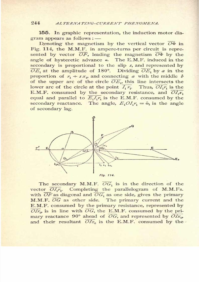
8/2/2019 Charles Steinmetz Theorycalculatio00steiiala
http://slidepdf.com/reader/full/charles-steinmetz-theorycalculatio00steiiala 270/557
244 AL TEKNA TING-CURRENT PHENOMENA.
155. In graphic representation, the induction motor dia-
gram appears as follows :
Denoting the magnetism by the vertical vector O<b in
Fig. 114, the M.M.F. in ampere-turns per circuit is repre-
sented by vector OF, leading the magnetism O<& by the
angle of hysteretic advance a. The E.M.F. induced in the
secondary is proportional to the slip s, and represented by
~OEl at the amplitude of 180. Dividing ~OEl by a in the
proportion of rt
-*- sxv and connecting a with the middle b
of the upper arc of the circle OEV this line intersects the
lower arc of the circle at the point 7Xrr Thus, OIj\ is the
E.M.F. consumed by the secondary resistance, and OI^equal and parallel to EJ^ is the E.M.F. consumed by the
secondary reactance. The angle, E^OI^\= ^ is the angle
of secondary lag.
\
The secondary M.M.F. OGl
is in the direction of the
vector OIfv Completing the parallelogram of M.M.Fs.
with OF as diagonal and OGlas one side, gives the primary
M.M.F. OG as other side. The primary current and the
E.M.F. consumed by the primary resistance, represented by
OIry is in line with OG, the E.M.F. consumed by the pri-
mary reactance 90 ahead of OG, and represented by OIxvand their resultant Ofz is the E.M.F. consumed by the

8/2/2019 Charles Steinmetz Theorycalculatio00steiiala
http://slidepdf.com/reader/full/charles-steinmetz-theorycalculatio00steiiala 271/557
INDUCTION MOTOR. 245
primary impedance. The E.M.F. induced in the primary
circuit is OE', and the E.M.F. required to overcome this
counter E.M.F. is OE equal and opposite to OE1
. Com-
bining OE with OIzQ gives the primary terminal voltage
represented by vector OEy and the angle of primary lag,
EOG
Fig. 115.
156. Thus far the diagram is essentially the same as
the diagram of the stationary alternating-current trans-
former. Regarding dependence upon the slip of the motor,
the locus of the different quantities for different values of
the slip s is determined thus,
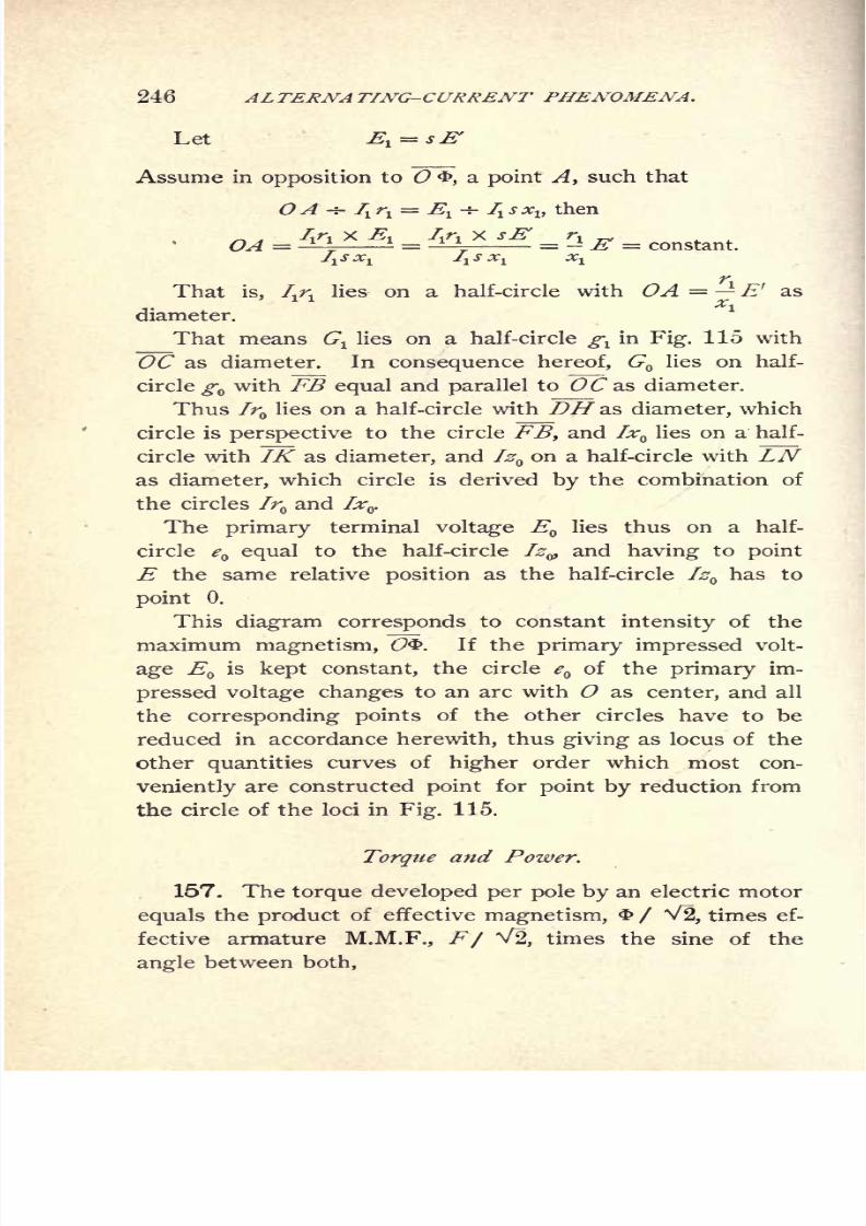
8/2/2019 Charles Steinmetz Theorycalculatio00steiiala
http://slidepdf.com/reader/full/charles-steinmetz-theorycalculatio00steiiala 272/557
246 ALTERNATING-CURRENT PHENOMENA.
Let l= s
f
Assume in opposition to O&, a point A, such that
OA -r- 7Xrx= E
v-* /! J.*!, then
/ir, x .", /ir, x sE r, _,= - ^ = constant.
That is, /^ lies on a half-circle with OA = E' as
diameter.
That means Gllies on a half-circle ^ in Fig. 115 with
OC as diameter. In consequence hereof, G lies on half-
circle^ with FB equal and parallel to OCas diameter.
Thus Ir lies on a half-circle with DH as diameter, which
circle is perspective to the circle FB, and Ix lies on a half-
circle with IK as diameter, and IzQon a half-circle with LN
as diameter, which circle is derived by the combination of
the circles Ir and Ixv
The primary terminal voltage EQlies thus on a half-
circle e equal to the half-circle Iz9 and having to point
E the same relative position as the half-circle Iz^ has to
point 0.
Thisdiagram corresponds
to constantintensity
of the
maximum magnetism, O. If the primary impressed volt-
age EQis kept constant, the circle e of the primary im-
pressed voltage changes to an arc with O as center, and all
the corresponding points of the other circles have to be
reduced in accordance herewith, thus giving as locus of the
other quantities curves of higher order which most con-
veniently are constructed point for point by reduction fromthe circle of the loci in Fig. 115.
Torque and Power.
157. The torque developed per pole by an electric motor
equals the product of effective magnetism, / V2, times ef-
fective armatureM.M.F.,
F/ V2,
times the sine of the
angle between both,

8/2/2019 Charles Steinmetz Theorycalculatio00steiiala
http://slidepdf.com/reader/full/charles-steinmetz-theorycalculatio00steiiala 273/557
INDUCTION MOTOR. 247
If!= number of turns, 7
t
=current, per circuit, with
/rarmature circuits, the total maximum current polarization,
or M.M.F. of the armature, is
Hence the torque per pole,
If q= the number of poles of the motor, the total torque
of the motor is,
The secondary induced E.M.F., Ev lags 90 behind the
inducing magnetism, hence reaches a maximum displaced in
space by 90 from the position of maximum magnetization.
Thus, if the secondary current, Iv lags behind its E.M.F.,
Ev by angle, <av the space displacement between armature
current and field magnetism is
hence sin (4> fj)= cos o^
We have, however,
thus, !<$
substituting these values in the equation of the torque, it is
T.
8/2/2019 Charles Steinmetz Theorycalculatio00steiiala
http://slidepdf.com/reader/full/charles-steinmetz-theorycalculatio00steiiala 274/557
248 ALTERNATING-CURRENT PHENOMENA.
or, in practical(C.G.S.)
units,
is the Torque of the Induction Motor.
At the slip s, the frequency N, and the number of poles
q, the linear speed at unit radius is
hence the output of the motor,
P= TV
or, substituted,
is the Power of the Induction Motor.
158. We can arrive at the same results in a different
way :
By the counter E.M.F. e of the primary circuit with
current /'
= f + 7Xthe power is consumed, e I = e I + e 7r
The power e I is that consumed by the primary hysteresis
and eddys. The power e 1^ disappears in the primary circuit
by being transmitted to the secondary system.
Thus the total power impressed upon the .secondary
system, per circuit, is
Pi-tf,
Of this power a part, 1fl,
is consumed in the secondary
circuit by resistance. The remainder,
P' = fl (e- 1),
disappears as electrical power altogether ; hence, by the law
of conservation of energy, must reappear as some other
form of energy, in this case as mechanical power, or as the
output of the motor (including friction).
Thus the mechanical output per motor circuit is
8/2/2019 Charles Steinmetz Theorycalculatio00steiiala
http://slidepdf.com/reader/full/charles-steinmetz-theorycalculatio00steiiala 275/557
INDUCTION MOTOR. 249
Substituting,
se;
se
it is
hence, since the imaginary part has no meaning as power,
and the total power of the motor,
At the linear speed,
at unit radius the torque is
In the foregoing, we found
= e\ 1 +j|?
+ Z, Y
or, approximately,
or,
expanded,
or, eliminating imaginary quantities,
8/2/2019 Charles Steinmetz Theorycalculatio00steiiala
http://slidepdf.com/reader/full/charles-steinmetz-theorycalculatio00steiiala 276/557
250 ALTERNATING-CURRENT PHENOMENA.
Substituting this value in the equations of torque and of
power, they become,
torque, T=
Maximum Torque.
159. The torque of the induction motor is a maximumfor that value of slip s, where
qpi r^ Eg s
or, since T= -. . T, .
4 7T JV^ (>1
for,
ds
expanded, this gives,
r 2
"7
or, st=
Substituting this in the equation of torque, we get thevalue of maximum torque,
That is, independent of the secondary resistance, rr
The power corresponding hereto is, by substitution of st
in P,
Pt = ;
This power is not the maximum output of the motor,
but already below the maximum output. The maximum
output is found at a lesser slip, or higher speed, while at
the maximum torque point the output is already on the
decrease, due to the decrease of speed.

8/2/2019 Charles Steinmetz Theorycalculatio00steiiala
http://slidepdf.com/reader/full/charles-steinmetz-theorycalculatio00steiiala 277/557
INDUCTION MOTOR. 251
With increasing slip, or decreasing speed, the torque of
the induction motor increases ; or inversely, with increasing
load, the speed of the motor decreases, and thereby the
torque increases, so as to carry the load down to the slip st,
corresponding to the maximum torque. At this point of
load and slip the torque begins to decrease again ;that is,
as soon as with increasing load, and thus increasing slip,
the motor passes the maximum torque point st,
it"falls out
of step," and comes to a standstill.
Inversely, the torque of the motor, when starting from
rest, will increase with increasing speed, until the maximum
torque point is reached. From there towards synchronism
the torque decreases again.
In consequence hereof, the part of the torque-speed
curve below the maximum torque point is in general un-
stable, and can be observed only by loading the motor
with an apparatus, whose countertorque increases with the
speed faster than the torque of the induction motor.
In general, the maximum torque point, st,
is between
synchronism and standstill, rather nearer to synchronism.
Only in motors of very large armature resistance, that is
low efficiency, st
> 1, that is, the maximum torque falls
below standstill, and the torque constantly increases from
synchronism down to standstill.
It is evident that the position of the maximum torque
point, stcan be varied by varying the resistance of the
secondary circuit, or the motor armature. Since the slip
of the maximum torque point, st ,
is directly proportional to
the armature resistance, rlf it follows that very constant
speed and high efficiency will bring the maximum torque
point near synchronism, and give small starting torque,
while good starting torque means a maximum torque point
at low speed ;that is, a motor with poor speed regulation*
and low efficiency.
Thus, to combine high efficiency and close speed regula-
tion with large starting torque, the armature resistance has
8/2/2019 Charles Steinmetz Theorycalculatio00steiiala
http://slidepdf.com/reader/full/charles-steinmetz-theorycalculatio00steiiala 278/557
252 ALTERNATING-CURRENT PHENOMENA.
to be varied during the operation of the motor, and the
motor started with
higharmature resistance, and with in-
creasing speed this armature resistance cut out as far as
possible.
160. If *=:1,__it is ^ = Vr 2 + (xl + *
)
2.
In this case the motor starts with maximum torque, and
when overloaded does not drop out of step, but gradually
slows down more and more, until it comes to rest.
If, st >l,
then ^ > Vr 2 + (^ + *)
2.
In this case, the maximum torque point is reached only
by driving the motor backwards, as countertorque.
As seen above, the maximum torque Tt,
is entirely in-
dependent of the armature resistance, and likewise is the
current corresponding thereto, independent of the armature
resistance. Only the speed of the motor depends upon the
armature resistance.
Hence the insertion of resistance into the motor arma-
ture does not change the maximum torque, and the current
corresponding thereto, but merely lowers the speed at whichthe maximum torque is reached.
The effect of resistance inserted into the induction motor
is merely to consume the E.M.F., which otherwise would
find its mechanical equivalent in an increased speed, analo-
gous as resistance in the armature circuit of a continuous-
current shunt motor.
Further discussion on the effect of armature resistance
is found under "Starting Torque."
Maximum Power.
161. The power of an induction motor is a maximum
for that slip,sv ,
where

8/2/2019 Charles Steinmetz Theorycalculatio00steiiala
http://slidepdf.com/reader/full/charles-steinmetz-theorycalculatio00steiiala 279/557
INDUCTION MOTOR. 253
expanded, this gives
sn-
substituted in P, we get the maximum power,
2{('i + ''o) + (^ + r
)
2 + (^i + *o)2
}
This result has a simple physical meaning :
(i\ + r)= r
is the total resistance of the motor, primary plus secondary
(the latter reduced to the primary), (x^ + x^ is the total
reactance, and thus Vrx
+ r)
2 +(x^
+ x}
z = z is the total
impedance of the motor. Hence
is the maximum output of the induction motor, at the slip,
The same value has been derived in Chapter IX., as the
maximum power which can be transmitted into a non-
inductive receiver circuit over a line of resistance r, and
impedance z, or as the maximum output of a generator, or
of a stationary transformer. Hence :
The maximum output of an induction motor is expressed
by the same formula as the maximum output of a generator,
or of a stationary transformer, or the maximum output which
can be transmitted over an inductive line into a non-inductive-
receiver circuit.
The torque corresponding to the maximum output Pp is,.
8/2/2019 Charles Steinmetz Theorycalculatio00steiiala
http://slidepdf.com/reader/full/charles-steinmetz-theorycalculatio00steiiala 280/557
254 ALTERNATING-CURRENT PHENOMENA.
This is not the maximum torque ;but the maximum
torque, Tt,takes place at a lower speed, that is, greater slip,
since,
-that is,s
t > sp .
It is obvious from these equations, that, to reach as large
an output as possible, r and z should be as small as possible ;
that is, the resistances ^ + r,and the impedances, z,
and thus the reactances, x + x,should be small. Since
r + r is usually small compared with x^ -f- x it follows, that
the problem of induction motor design consists in con-
structing the motor so as to give the minimum possible
reactances, x^ + x .
Starting Torque.
162. In the moment of starting an induction motor,
the slip is
hence, starting current,
Oo-
or, expanded, with the rejection of the last term in the
denominator, as insignificant,
T _io 11 010 ,io 1.
- 8
and, displacement of phase, or angle of lag,
fi + r] + *! [Jfx 4- Jf
])-
jf (r ^ - * rt)
1 W
r )
8/2/2019 Charles Steinmetz Theorycalculatio00steiiala
http://slidepdf.com/reader/full/charles-steinmetz-theorycalculatio00steiiala 281/557
INDUCTION MOTOR. 255
Neglecting the exciting current, g = =b, these equa-
tions assume the form,
or, eliminating imaginary quantities,
and tan w =+ 'o
That means, that in starting the induction motor without
additional resistance in the armature circuit, in which case
^ + x is large compared with t\ + r , and the total impe-
dance, z, small, the motor takes excessive and greatly
lagging currents.
The starting torque is
T =
That is, the starting torque is proportional to the
armature resistance, and inversely proportional to the square
of the total impedance of the motor.
It is obvious thus, that, to secure large starting torque,
the impedance should be as small, and the armature resis-
tance as large, as possible. The former condition is the
condition of large maximum output and good efficiency
and speed regulation ;the latter condition, however, means
inefficiency and poor regulation, and thus cannot properly
be fulfilled by the internal resistance of the motor, but only
byan additional resistance which is short-circuited while
the motor is in operation.

8/2/2019 Charles Steinmetz Theorycalculatio00steiiala
http://slidepdf.com/reader/full/charles-steinmetz-theorycalculatio00steiiala 282/557
256 ALTERNATING-CURRENT PHENOMENA.
Since, necessarily,
ri<*,
''<<and since the starting current is, approximately,
7 =f ,
we have, Ta <
would be the theoretical torque developed at 100 per cent
efficiency and power factor, by E.M.F., E ,and current, /,
at synchronous speed.
Thus, T0< T00,
and the ratio between the starting torque T ,and the theo-
retical maximum torque, T^, gives a means to judge the
perfection of a motor regarding its starting torque.
This ratio, T / Tw ,exceeds .9 in the best motors.
Substituting 7 = E / z in the equation of starting torque,
it assumes the form,
7V,.
Since 4 ITN/ q=
synchronous speed, it is :
The starting torque of the induction motor is equal to the
resistance loss in the motor armature, divided by the synchro-
nous speed.
The armature resistance which gives maximum starting
torque is

8/2/2019 Charles Steinmetz Theorycalculatio00steiiala
http://slidepdf.com/reader/full/charles-steinmetz-theorycalculatio00steiiala 283/557
INDUCTION MOTOR. 257
dr,
expanded, this gives,
the same value as derived in the paragraph on "maximumtorque."
Thus, adding to the internal armature resistance, r/ in
starting the additional resistance,
makesthe
motorstart with
maximum torque, while with in-
creasing speed the torque constantly decreases, and reaches
zero at synchronism. Under these conditions, the induc-
tion motor behaves similarly to the continuous-current series
motor, varying in the speed with the load, the difference
being, however, that the induction motor approaches a
definite speed at no load, while with the series motor the
speed indefinitely increases with decreasing load.
The additional armature resistance, t\", required to give
a certain starting torque, if found from the equation of
starting torque :
Denoting the internal armature resistance by rj, the total
armature resistance is ^ = r^ + r".
and thus, ?A Eg rj + r"4 TTN (r^ + r^ + r
)
2 + (Xl + *)
2 '
hence,
This gives two values, one above, the other below, the
maximum torque point.

8/2/2019 Charles Steinmetz Theorycalculatio00steiiala
http://slidepdf.com/reader/full/charles-steinmetz-theorycalculatio00steiiala 284/557
258 ALTERNATING-CURRENT PHENOMENA.
Choosing the positive sign of the root, we get a larger
armature resistance, a small current in starting, but the
torque constantly decreases with the speed.
Choosing the negative sign, we get a smaller resistance,
a large starting current, and with increasing speed the
torque first increases, reaches a maximum, and then de-
creases again towards synchronism.
These two points correspond to the two points of the
speed-torque curve of the induction motor, in Fig. 116,
giving the desired torque T .
The smaller value of r1
"will give fairly good speed regu-
lation, and thus in small motors, where the comparatively
large starting current is no objection, the permanent arma-
ture resistance may be chosen to represent this value.
The larger value of rj' allows to start with minimum
current, but requires cutting out of the resistance after the
start, to secure speed regulation and efficiency.
Synchronism.
163. At synchronism, s = 0, we have,
or,
0, T=Q;
that is, power and torque are zero. Hence, the induction
motor can never reach complete synchronism, but must
slip sufficiently to give the torque consumed by friction.
Running near Synchronism.
164. When running near synchronism, at a slip s above
the maximum output point, where s is small, from .02 to
.05 at full load, the equations can be simplified by neglect-
ing terms with s, as of higher order.
8/2/2019 Charles Steinmetz Theorycalculatio00steiiala
http://slidepdf.com/reader/full/charles-steinmetz-theorycalculatio00steiiala 285/557
INDUCTION MOTOR. 25
We then have, current,
or, eliminating imaginary quantities,
angleof
lag,o*i
+*o
,
c2 (r_ -I- <r_\ -4- r.2 h r.
tan w
T=
or, inversely,
AA
that is,
Near sychronism, the slip, s, of an induction motor, or
its drop in speed, is proportional to the armature resistance>
i\and to the power, P, or torque, T.
Example.
165. As an instance are shown, in Fig. 116, character-
istic curves of a 20 horse-power three-phase induction motor,
of 900 revolutions synchronous speed, 8 poles, frequency
of 60 cycles.
The impressed E.M.F. is 110 volts between lines, and
the motor star connected, hence the E.M.F. impressed per
circuit :
= 63.5 ; or EQ = 63.5.
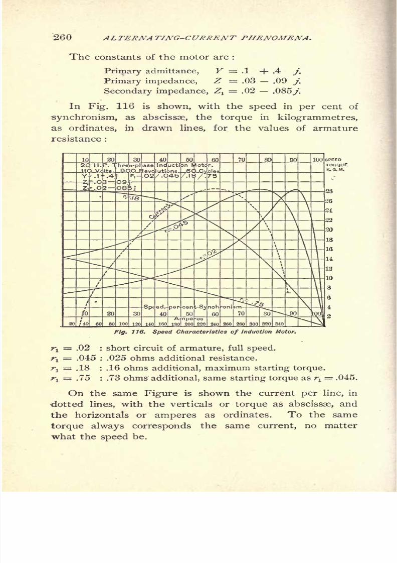
8/2/2019 Charles Steinmetz Theorycalculatio00steiiala
http://slidepdf.com/reader/full/charles-steinmetz-theorycalculatio00steiiala 286/557
260 AL TERNA TING-CURRENT PHENOMENA.
The constants of the motor are :
Primary admittance, Y = .1 + .4 j.
Primary impedance, Z = .03 .09 j.
Secondary impedance, Zx= .02 .085/.
In Fig. 116 is shown, with the speed in per cent of
synchronism, as abscissae, the torque in kilogrammetres,
as ordinates, in drawn lines, for the values of armature
resistance :
116. Speed Characteristics of Induction Motor.
rt= .02 : short circuit of armature, full speed.
^= .045 : .025 ohms additional resistance.
^ = .18 : .16 ohms additional, maximum starting torque.
^ = .75 : .73 ohms additional, same starting torque as rt== .045.
On the same Figure is shown the current per line, in
dotted lines, with the verticals or torque as abscissae, and
the horizontals or amperes as ordinates. To the same
torque always corresponds the same current, no matter
what the speed be.

8/2/2019 Charles Steinmetz Theorycalculatio00steiiala
http://slidepdf.com/reader/full/charles-steinmetz-theorycalculatio00steiiala 287/557
INDUCTION MOTOR. 261
On Fig. 117 is shown, with the current input per line as
abscissae, the torque in kilogrammetres and the output in
horse-power as ordinates in drawn lines, and the speed and
the magnetism, in per cent of their synchronous values, as
ordinates in dotted lines, for the armature resistance ^ = .02
or short circuit.
20 lase Induotio Motor.
. 60Cyc10V
Jiagram
=.03-.09jz0=J&B
\
\\
\\
12
-1
Amperes150
1 200 2,50 300
Fig. 117. Current Characteristics of Induction Motor.
In Fig. 118 is shown, with the speed, in per cent of
synchronism, as abscissae, the torque in drawn line, and
theoutput
in dottedline,
for the value of armature resist-
ance?i= .045, for the whole range of speed from 120 per
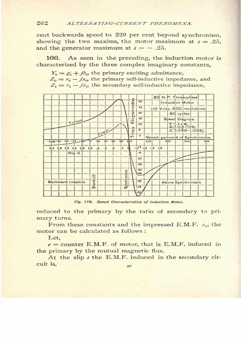
8/2/2019 Charles Steinmetz Theorycalculatio00steiiala
http://slidepdf.com/reader/full/charles-steinmetz-theorycalculatio00steiiala 288/557
262 ALTERNA TING-CURRENT PHENOMENA.
cent backwards speed to 220 per cent beyond synchronism,
showing the two maxima, the motor maximum at s = .25,
and the generator maximum at s = .25.
166. As seen in the preceding, the induction motor is
characterized by the three complex imaginary constants,
Y = g +jbw the primary exciting admittance,
Z = r jx ,the primary self-inductive impedance, and
Zi
= rjx^
thesecondary
self-inductive
impedance,
Fig. 1 18. Speed Characteristics of Induction Motor.
reduced to the primary by the ratio of secondary to pri-
mary turns.
From these constants and the impressed E.M.F. cot
the
motor can be calculated as follows :
Let,
e = counter E.M.F. of motor, that is E.M.F. induced in
the primary by the mutual magnetic flux.
At the slip s the E.M.F. induced in the secondary cir-
cuit is, se
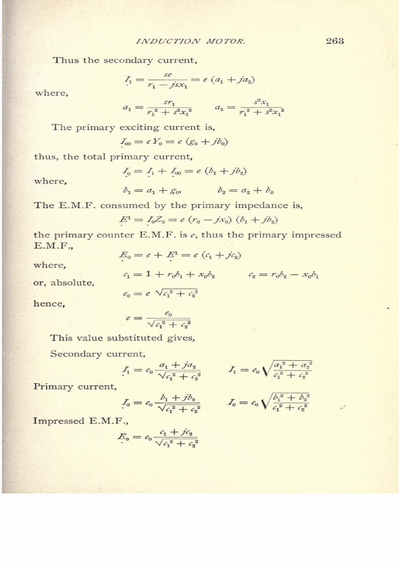
8/2/2019 Charles Steinmetz Theorycalculatio00steiiala
http://slidepdf.com/reader/full/charles-steinmetz-theorycalculatio00steiiala 289/557
INDUCTION MOTOR. 263
Thus the secondary current,
where,
l= -5T
r* + Atf r? +
The primary exciting current is,
thus, the total primary current,
/ =/! + /oo
= *(^i +A)
where,
The E.M.F. consumed by the primary impedance is,
^ = /oZ = * (r -> ) (^
the primary counter E.M.F. is e, thus the primary impressed
E.M.F.,
,
where,
c\
or, absolute,
^ =hence,
This value substituted gives,
Secondary current,
ffi+AA = *b T7=
Primary current,
~
Impressed E.M.F.,
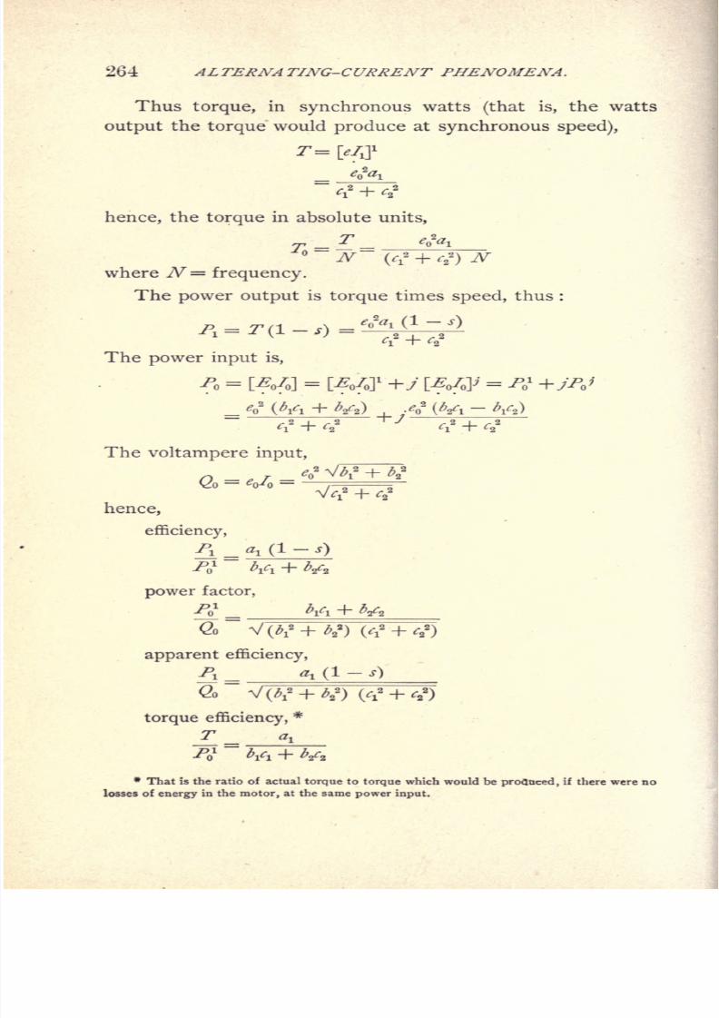
8/2/2019 Charles Steinmetz Theorycalculatio00steiiala
http://slidepdf.com/reader/full/charles-steinmetz-theorycalculatio00steiiala 290/557
264 ALTERNATING-CURRENT PHENOMENA.
Thus torque, in synchronous watts (that is, the watts
output the torque would produce at synchronous speed),
tf + tf
hence, the torque in absolute units,
= =
N (f* + r22
)
Wwhere N= frequency.
The power output is torque times speed, thus :
The power input is,
^l
2 +
The voltampere input,
o
2
(Vi + V,) /o2
(Vi - V8 )
hence,
efficiency,
J\ _ a, (I-
s)
J? Vi + V2
power factor,
apparent efficiency,
<2o
torque efficiency,*
a.
./V Vi + V.
* That 5s the ratio of actual torque to
torquewhich would be
profloced,
if there were nc
losses of energy in the motor, at the same power input.
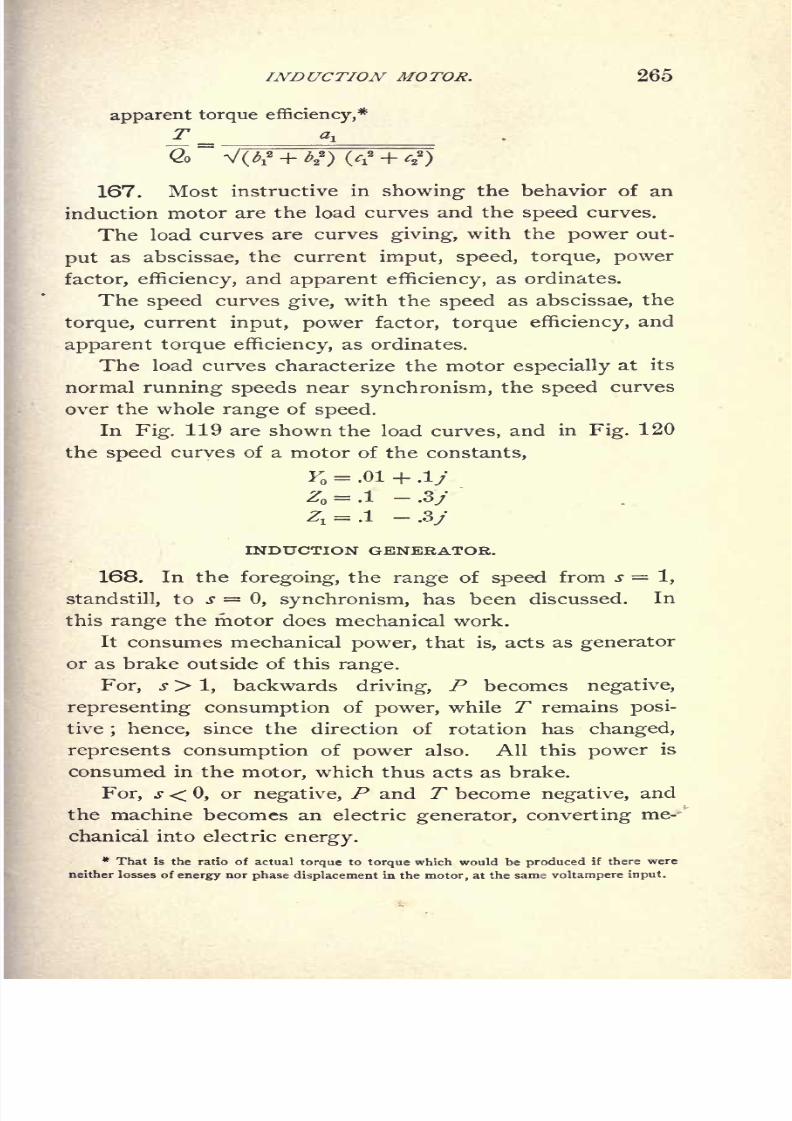
8/2/2019 Charles Steinmetz Theorycalculatio00steiiala
http://slidepdf.com/reader/full/charles-steinmetz-theorycalculatio00steiiala 291/557
INDUCTION MOTOR. 265
apparent torque efficiency,*rrt
~Q~ VW~+1?YT^
167. Most instructive in showing the behavior of an
induction motor are the load curves and the speed curves.
The load curves are curves giving, with the power out-
put as abscissae, the current imput, speed, torque, power
factor, efficiency,and
apparent efficiency,as ordinates.
The speed curves give, with the speed as abscissae, the
torque, current input, power factor, torque efficiency, and
apparent torque efficiency, as ordinates.
The load curves characterize the motor especially at its
normal running speeds near synchronism, the speed curves
over the whole range of speed.
In Fig. 119 are shown the load curves, and in Fig. 120the speed curves of a motor of the constants,
K = .01 + .!/
z* = .i -.3>
Z, = .1 -.3j
INDUCTION GENERATOR.
168. In the foregoing, the range of speed from s = 1,
standstill, to s = 0, synchronism, has been discussed. In
this range the motor does mechanical work.
It consumes mechanical power, that is, acts as generator
or as brake outside of this range.
For, s > 1, backwards driving, P becomes negative,
representing consumption of power, while T remains posi-
tive; hence, since the direction of rotation has changed,
represents consumption of power also. All this power is
consumed in the motor, which thus acts as brake.
For, s < 0, or negative, P and T become negative, and
the machine becomes an electric generator, converting me-
chanical into electric energy.
* That is the ratio of actualtorque
totorque
whichwould
beproduced
if there were
neither losses of energy nor phase displacement in the motor, at the same voltampere input.

8/2/2019 Charles Steinmetz Theorycalculatio00steiiala
http://slidepdf.com/reader/full/charles-steinmetz-theorycalculatio00steiiala 292/557
266 ALTERNA TING-CURRENT PHENOMENA.
The calculation of the induction generator at constant
frequency, that is, at a speed increasing with theload
by the
negative slip,slt
is the same as that of the induction motor
except that slhas negative values, and the load curves for
the machine shown as motor in Fig. 119 are shown in Fig.
121 for negative slip s{as induction generator.
CURV
POWER
4000 ">Fig. 119.
Again, a maximum torque point and a maximum output
point are found, and the torque and power increase from
zero at synchronism up to a maximum point, and then de-
crease again, while the current constantly increases.
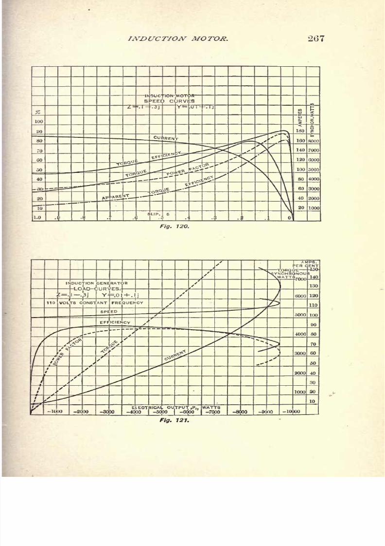
8/2/2019 Charles Steinmetz Theorycalculatio00steiiala
http://slidepdf.com/reader/full/charles-steinmetz-theorycalculatio00steiiala 293/557
INDUCTION MOTOR. 267
Fig. 120.
8/2/2019 Charles Steinmetz Theorycalculatio00steiiala
http://slidepdf.com/reader/full/charles-steinmetz-theorycalculatio00steiiala 294/557
268 ALTERNATING-CURRENT PHENOMENA.
169. The induction generator differs essentially from
the ordinary synchronous alternator in so far as the induc-
tion generator has a definite power factor, while the syn-
chronous alternator has not. That is, in the synchronous
alternator the phase relation between current and terminal
voltage entirely depends upon the condition of the external
circuit. The induction generator, however, can operate
only if the phase relation of current and E.M.F., that is, the
power factor required by the external circuit, exactly coin-
cides with the internal power factor of the induction gen-
erator. This requires that the power factor either of the
external circuit or of the induction generator varies with
the voltage, so as to permit the generator and the external
circuit to adjust themselves to equality of power factor.
Beyond magneticsaturation the
powerfactor decreases
;
that is, the lead of current increases in the induction ma-
chine. Thus, when connected to an external circuit of con-
stant power factor the induction generator will either not
generate at all, if its power factor is lower than that of the
external circuit, or, if its power factor is higher than that of
the external circuit, the voltage will rise until by magnetic
saturation in the induction generator its power factor hasfallen to equality with that of the external circuit. This,
however, requires magnetic saturation in the induction gen-
erator, which is objectionable, due to excessive hysteresis
losses in the alternating field.
To operate below saturation, that is, at constant inter-
nal power factor, the induction generator requires an exter-
nal circuit with leading current, whose power factor varies
with the voltage, as a circuit containing synchronous motors
or synchronous converters. In such a circuit, the voltage
of the induction generator remains just as much below the
counter E.M.F. of the synchronous motor as necessary to
give the required leading exciting current of the induction
generator, and the synchronous motor can thus to a certain
extent be called the exciter of the induction generator.

8/2/2019 Charles Steinmetz Theorycalculatio00steiiala
http://slidepdf.com/reader/full/charles-steinmetz-theorycalculatio00steiiala 295/557
INDUCTION MOTOR. 269
When operating self-exciting, that is shunt-wound, con-
verters from the induction generator, below saturation of
both the converter and the induction generator, the condi-
tions are unstable also, and the voltage of one of the two
machines must rise beyond saturation of its magnetic field.
When operating in parallel with synchronous alternat-
ing generators, the induction generator obviously takes its
leading exciting current from the synchronous alternator,
which thus carries a lagging wattless current.
170. To generate constant frequency, the speed of the
induction generator must increase with the load. Inversely,
when driven at constant speed, with increasing load on the
induction generator, the frequency of the current generated
thereby decreases. Thus, when calculating the character-
istic curves of the constant speed induction generator, due
regard has to be taken of the decrease of frequency with
increase of load, or what may be called the slip of fre-
quency, s.
Let in an induction generator,
Y = gQ + j\ primary exciting admittance,
Z = r jxQ = primary self-inductive impedance,
Zi=
r^ jXj_=
secondary self-inductive impedance,
reduced to primary, all these quantities being reduced to
the frequency of synchronism with the speed of the ma-
chine, N.
Let e induced E.M.F., reduced to full frequency.
s = slip of
frequency,
thus :
(1-j)
N=frequency gener-
ated by machine.
We then have
Secondary induced E.M.F.
se
thus, secondary current,
r in\ Jsx\

8/2/2019 Charles Steinmetz Theorycalculatio00steiiala
http://slidepdf.com/reader/full/charles-steinmetz-theorycalculatio00steiiala 296/557
270 ALTERNATING-CURRENT PHENOMENA.
where,
primary exciting current,
In = EY = e
thus, total primary current,
/ =/i +
foo
where,
^1=
<*\ + b
primary impedance voltage,
& = S (r-
primary induced E.M.F.,
thus, primary terminal voltage,
= e(l-s) -S (r -j[l- s]x
)= e
where,
fi= ! - s ~ rA -
(1- s
hence, absolute,
e = e V^and,
Thus,
Secondary current,
TeO (a
i
Primary current,
j _ eo (A +A)
Primary terminal voltage,
j-. ^0 \^"l=T-,
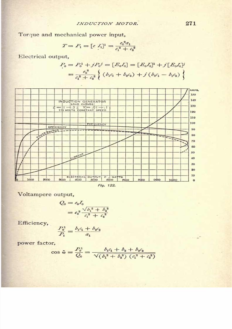
8/2/2019 Charles Steinmetz Theorycalculatio00steiiala
http://slidepdf.com/reader/full/charles-steinmetz-theorycalculatio00steiiala 297/557
INDUCTION MOTOR.
Torque and mechanical power input,
T P \f n le air*
~\-
e ^ ~7^+^
Electrical output,
271
ELECTRICAL OUTPUT P,WATTS
1000 2000 3COO 4000 fiOOO fiOOO 7000 8000
Fig. 122.
Voltampere output,
G, = <
Efficiency,
j
power factor,
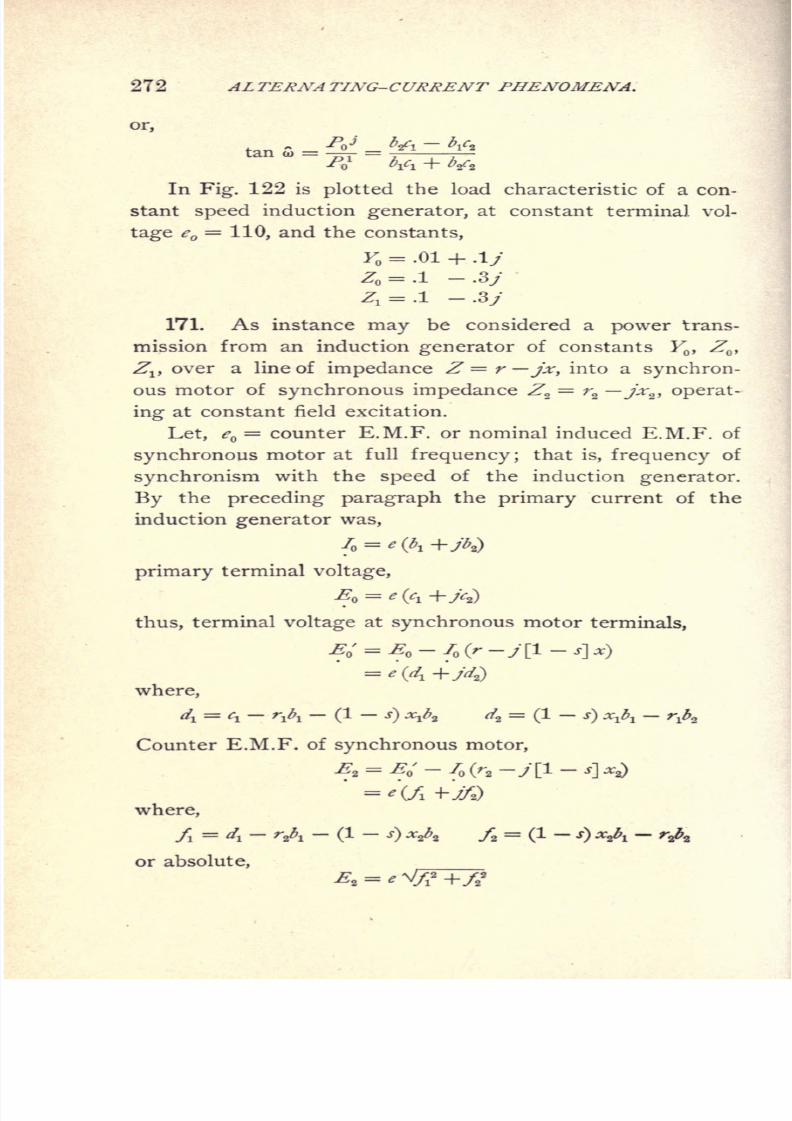
8/2/2019 Charles Steinmetz Theorycalculatio00steiiala
http://slidepdf.com/reader/full/charles-steinmetz-theorycalculatio00steiiala 298/557
272 AL TERNA TING-CURRENT PHENOMENA.
or,
p,j b* - V,=^-
=^T^In Fig. 122 is plotted the load characteristic of a con-
stant speed induction generator, at constant terminal vol-
tage e =110, and the constants,
K = .01 + .!/
171. As instance may be considered a power trans-
mission from an induction generator of constants Y,Z
,
Zj, over a line of impedance Z = r jx, into a synchron-
ous motor of synchronous impedance Zz= r
z jxz , operat-
ing at constant field excitation.
Let, e = counter E.M.F. or nominal induced E.M.F. of
synchronous motor at full frequency ;that is, frequency of
synchronism with the speed of the induction generator.
By the preceding paragraph the primary current of the
induction generator was,
primary terminal voltage,
E = e
thus, terminal voltage at synchronous motor terminals,
where,
4=
fi
~ r
A~
C
1 - J) *A 4
=
Counter E.M.F. of synchronous motor,
E2
'
where,
/ = 4 - r& -(1
or absolute,
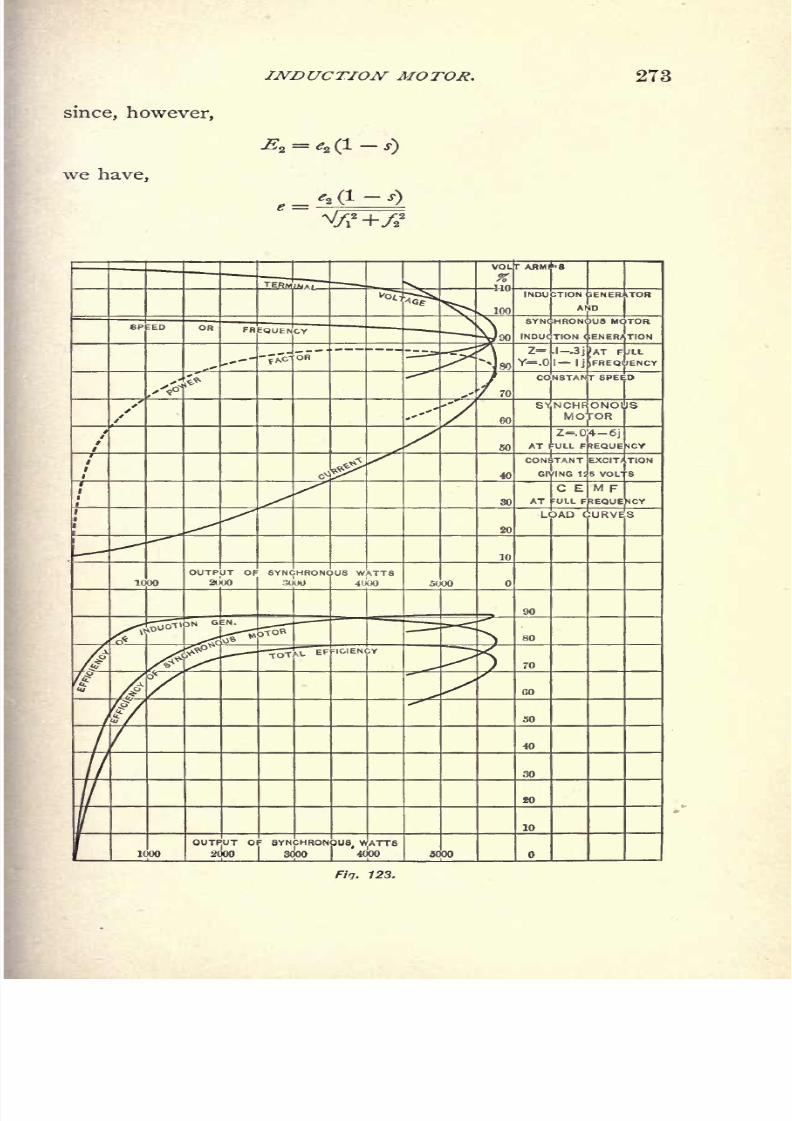
8/2/2019 Charles Steinmetz Theorycalculatio00steiiala
http://slidepdf.com/reader/full/charles-steinmetz-theorycalculatio00steiiala 299/557
INDUCTION MOTOR.
since, however,
Z=.0|4-6jULL F EQUE
EXCIT/
5 VOL'
OUTPUT OF SYNCHRONOUS, WATTS
1000 2000 I 8000 4000 5000

8/2/2019 Charles Steinmetz Theorycalculatio00steiiala
http://slidepdf.com/reader/full/charles-steinmetz-theorycalculatio00steiiala 300/557
274 ALTERNATING-CURRENT PHENOMENA.
Thus,
Current, _ e2 (1 - j) (^ +y7;2)
Terminal voltage at induction generator,
Terminal voltage at synchronous motor,
and herefrom in the usual way the efficiencies, power fac-
tor, etc. are derived.
When operated from an induction generator, a syn-
chronous motor gives a load characteristic very similar to
that of an induction motor operated from a synchronous
generator, but in the former case the current is leading, in
the latter lagging.
In either case, the speed gradually falls off with increas-
ing load(in
the synchronous motor, due to the falling off
of the frequency of the induction generator), up to a maxi-
mumoutput point,
where the motordrops
out of
step
and
comes to standstill.
Such a load characteristic of the induction generator in
Fig. 121, feeding a synchronous motor of counter E.M.F.
eQ= 125 volts
(atfull frequency) and synchronous impe-
dance Z2= .04 Gj, over a line of negligible impedance
is shown in Fig. 123.
CONCATENATION, OR TANDEM CONTROL OF INDUCTIONMOTORS.
172. If of two induction motors the secondary of the
first motor is connected to the primary of the second motor,
the second machine operates as motor with the E.M.F. and
frequency impressed upon it by the secondary of the first
machine, which acts as general alternating-current trans-
former, converting a part of the primary impressed power
8/2/2019 Charles Steinmetz Theorycalculatio00steiiala
http://slidepdf.com/reader/full/charles-steinmetz-theorycalculatio00steiiala 301/557
INDUCTION MOTOR. 275
into secondary electrical power for the supply of the second
machine, and a part into mechanical work.
The frequency of the secondary E.M.F. of the first motor,
and thus the frequency impressed upon the second motor, is
the frequency of slip below complete synchronism, s. The
frequency of the secondary induced E.M.F. of the second
motor is the difference between its impressed frequency,
s, and its speed ; thus, if both motors are connected together
mechanically to turn at the same speed, 1 s, the secondary
frequency of the second motor is 2^1, hence equal to
zero at s = .5. That is, the second motor reaches its syn-
chronism at half speed. At this speed its torque becomes
equal to zero, the energy current flowing into it, and conse-
quently the energy component of the secondary current of
the first
"motor,and thus the
torqueof the first motor be-
comes equal to zero also, when neglecting the hysteresis
energy current of the second motor. That is, a system of
concatenated motors with short-circuited secondary of the
second motor approaches half synchronism, in the same
manner as the ordinary induction motor approaches syn-
chronism. With increasing load, its slip below half syn-
chronism increases.
More generally, any pair of induction motors connected
in concatenation divide the speed so that the sum of their
two respective speeds approaches synchronism at no load;
or, still more generally, any number of concatenated motors
run at such speeds that the sum of the speeds approaches
synchronism at no load.
With mechanical connection between the two motors,
concatenation thus offers a means to operate a pair of
induction motors at full efficiency at half speed in tandem,
as well as at full speed in parallel, and thus gives the same
advantage as the series-parallel control of the continuous-
current motor.
In starting, a concatenated
system
is controlled by re-
sistance in the armature of the second motor.
8/2/2019 Charles Steinmetz Theorycalculatio00steiiala
http://slidepdf.com/reader/full/charles-steinmetz-theorycalculatio00steiiala 302/557
276 ALTERNATING-CURRENT PHENOMENA.
Since, with increasing speed, the frequency impressed
upon the second motor decreases proportionally to the de-
crease of voltage, when neglecting internal losses in the
first motor, the magnetic density of the second motor re-
mains practically constant, and thus its torque the same as
when operated at full voltage and full frequency under the
same conditions.
At half synchronism the torque of the concatenated
couple becomes zero, and above half synchronism the sec-
ond motor runs beyond its impressed frequency ;that is,
becomes generator. In this case, due to the reversal of
current in the secondary of the first motor, its torque
becomes negative also, that is the concatenated couple
becomes induction generator above half synchronism. At
about two-thirds synchronism, with low resistance armature,
the torque of the couple becomes zero again, and once more
positive between about two-thirds synchronism and full syn-
chronism, and negative once more beyond full synchronism.
With high resistance in the secondary of the second motor,
the second range of positive torque, below full synchronism,
disappears, more or less.
173. The calculation of a concatenated couple of in-
duction motors is as follows,
Let
N =frequency of main circuit,
s = slip of the first motor from synchronism.
the frequency induced in the secondary of the first motor
and thus impressed upon the primary of the second motor
is, s N.
The^peed of the first motor is(1 s) N, thus the slip
of the second motor, or the frequency induced in its sec-
ondary, is
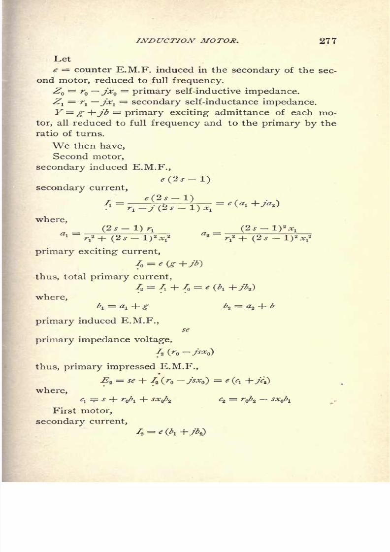
8/2/2019 Charles Steinmetz Theorycalculatio00steiiala
http://slidepdf.com/reader/full/charles-steinmetz-theorycalculatio00steiiala 303/557
INDUCTION MOTOR. 277
Let
e = counter E.M.F. induced in the secondary of the sec-
ond motor, reduced to full frequency.
Z = r jxQ=
primary self-inductive impedance.
Z^=
i\ jxv
=secondary self-inductance impedance.
Y g +jb = primary exciting admittance of each mo-
tor, all reduced to full frequency and to the primary by the
ratio of turns.
We then have,
Second motor,
secondary induced E.M.F.,
*(*/-!)secondary current,
where,
(2s-l)r1
i~r*+ (2 J -1)
2 ^1
2 z~r*+ (2s-
primary exciting current,
4 = * (g +JI>}
thus, total primary current,
72 = 7, + 7 = e(
where,
primary induced E.M.F.,
se
primary impedance voltage,
ft (
ro >^o)
thus, primary impressed E.M.F.,
3= se + 72 (r -jsx )
= e (^
where,
First motor,
secondarycurrent,

8/2/2019 Charles Steinmetz Theorycalculatio00steiiala
http://slidepdf.com/reader/full/charles-steinmetz-theorycalculatio00steiiala 304/557
278 ALTERNATING-CURRENT PHENOMENA.
secondary induced E.M.F.,
9 =
where,
primary induced E.M.F.,
EI = -
where,
s
primary exciting current,
total primary current,
where,
primary impedance voltage,
|(>o ~>
thus,
primaryimpressed E.M.F.,
= E, + S(r ->where,
^i =/i + ^o5i + *ba
or, absolute,
<-
and,
VV + V
Substituting now this value of ^ in the preceding gives
the values of the currents and E.M.F.'s in the different
circuits of the motor series.
* At s = theseterms/i and/s
becomeindefinite,
and thus at andvery
nearsynchronism
have to be derived by substituting the complete expressions fory^ andy"2 .
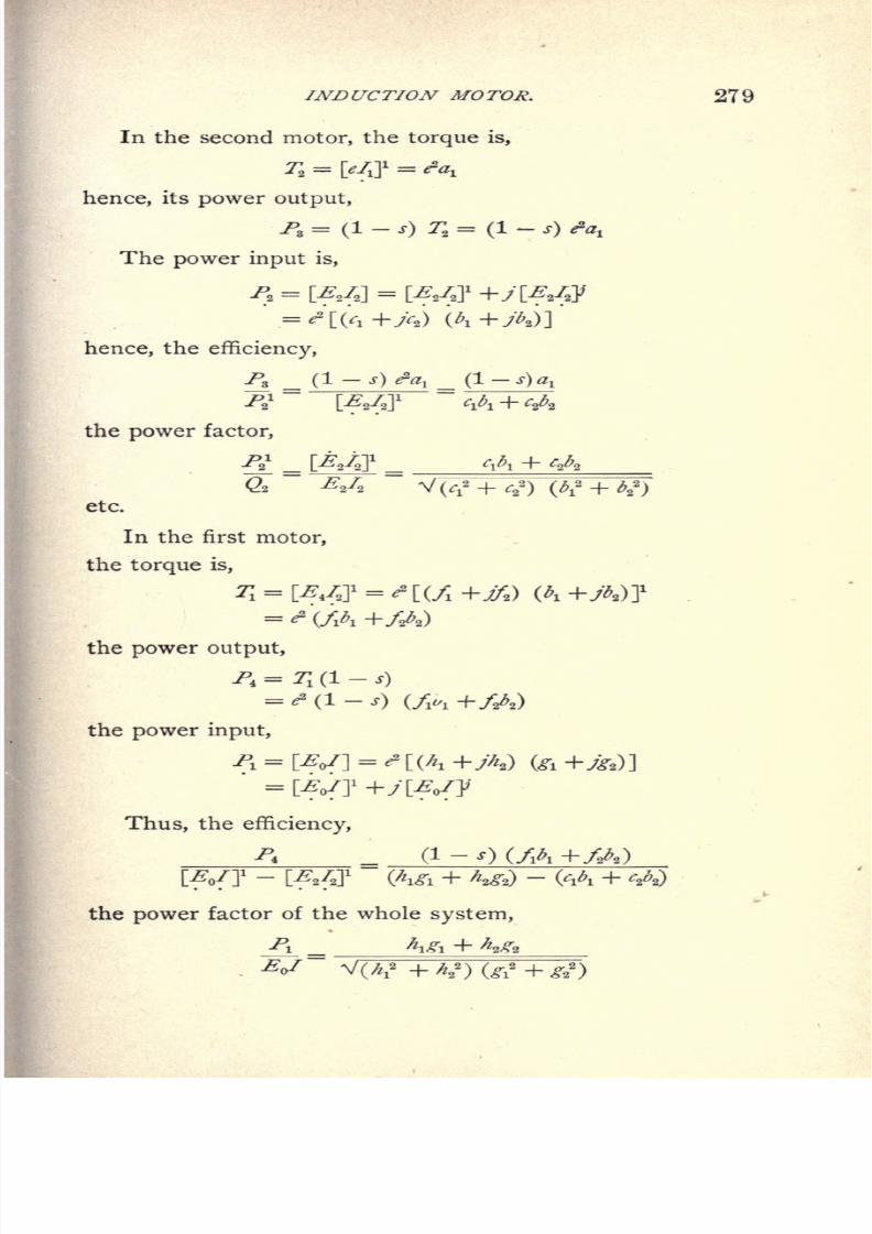
8/2/2019 Charles Steinmetz Theorycalculatio00steiiala
http://slidepdf.com/reader/full/charles-steinmetz-theorycalculatio00steiiala 305/557
INDUCTION MOTOR. 279
In the second motor, the torque is,
T =[,/J
=^hence, its power output,
/,= (!- s) r2=
(1-
s) <?ai
The power input is,
hence, the efficiency,
PS (1-
s) fa,
the power factor,
etc.
In the first motor,
the torque is,
the power output,
PI = 71 (1-
j)
= ^ (1-
,) (/^ -h/A)
the power input,
P1=
Thus, the efficiency,
^ (1- Q (/A +/A)+ 2̂)
- (^ +
the power factor of the whole system,
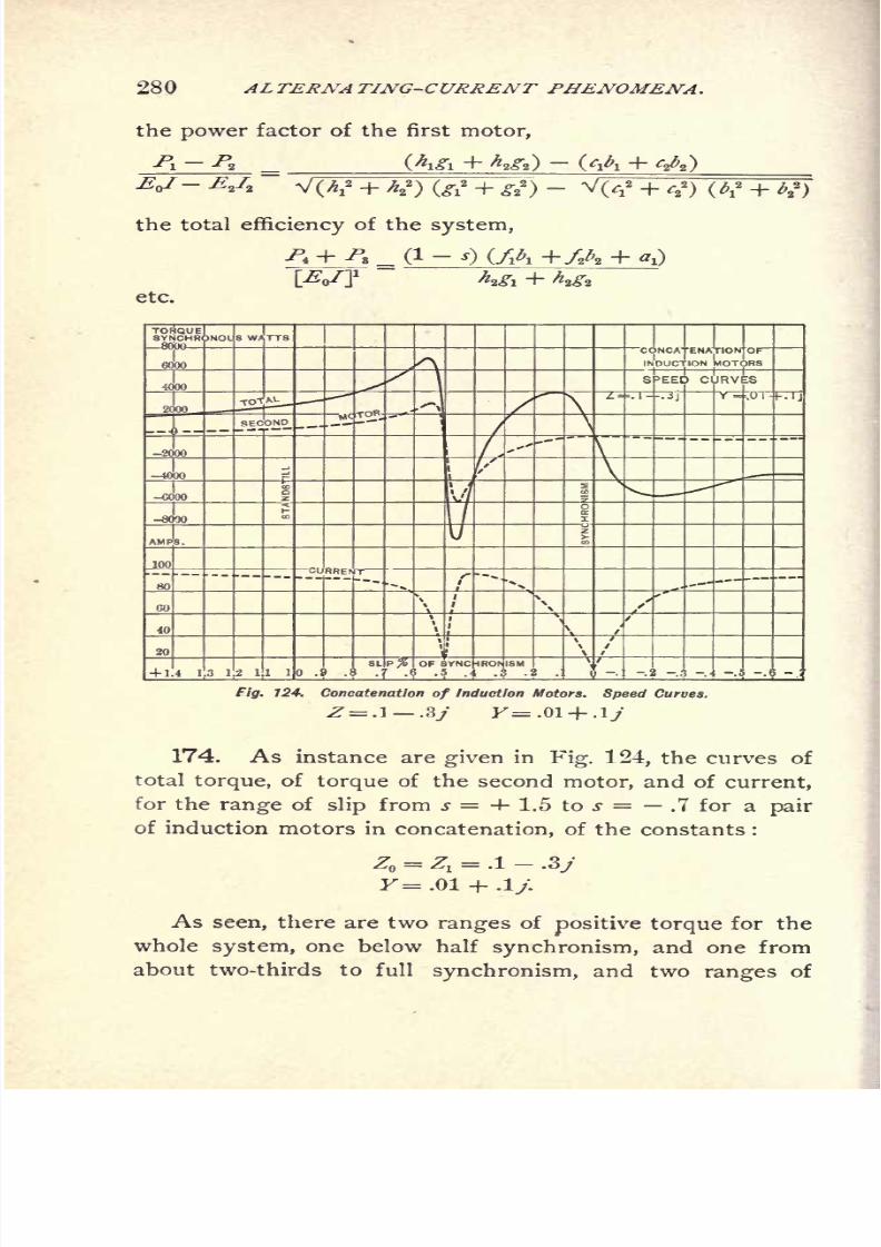
8/2/2019 Charles Steinmetz Theorycalculatio00steiiala
http://slidepdf.com/reader/full/charles-steinmetz-theorycalculatio00steiiala 306/557
280 ALTERNATING-CURRENT PHENOMENA.
the power factor of the first motor,
the total efficiency of the system,
etc.
f/ff. 724. Concatenation of Induction Motors. Speed Curves.
Z=.1 .3/ K=.01 + .l>
174. As instance are given in Fig. 124, the curves of
total torque, of torque of the second motor, and of current,
for the range of slip from s = + 1.5 to s = .7 for a pair
of induction motors in concatenation, of the constants :
Z =Z, = .1 - .Bj
As seen, there are two ranges ofpositive torque for the
whole system, one below half synchronism, and one from
about two-thirds to full synchronism, and two ranges of

8/2/2019 Charles Steinmetz Theorycalculatio00steiiala
http://slidepdf.com/reader/full/charles-steinmetz-theorycalculatio00steiiala 307/557
INDUCTION MOTOR. 281
negative torque, or generator action of the motor, from half
to two-third synchronism, and above full synchronism.
With higher resistance in the secondary of the second
motor, the second range of positive torque of the system
disappears more or less, and the torque curves become as
shown in Fig. 125.
Fig. 125. Concatenation of Induction Motors. Speed Curves.
SINGLE-PHASE INDUCTION MOTOR.
175. The magnetic circuit of the induction motor at or
near synchronism consists of two magnetic fluxes super-
imposed upon each other in quadrature, in time, and in
position. In the polyphase motor these fluxes are produced
by E.M.Fs. displaced in phase. In the monocyclic motor
one of the fluxes is due to the primary energy circuit, the
other to the circuit. In the
8/2/2019 Charles Steinmetz Theorycalculatio00steiiala
http://slidepdf.com/reader/full/charles-steinmetz-theorycalculatio00steiiala 308/557
282 ALTERNA TING-CURRENT PHENOMENA.
motor the one flux is produced by the primary circuit, the
other by the currents induced in the secondary or armature,
which are carried into quadrature position by the rotation
of the armature. In consequence thereof, while in all these
motors the magnetic distribution is the same at or near syn-
chronism, and can be represented by a rotating field of
uniform intensity and uniform velocity, it remains such in
polyphase and monocyclic motors;but in the single-phase
motor, with increasing slip, that is, decreasing speed,
the quadrature field decreases, since the induced armature
currents are not carried to complete quadrature position ;
and thus only a component available for producing the
quadrature flux. Hence, approximately, the quadrature flux
of a single-phase motor can be considered as proportional to
its
speed;that
is,
it is zero at standstill.
Since the torque of the motor is proportional to the
product of secondary current times magnetic flux in quad-
rature, it follows that the torque of the single-phase motor
is equal to that of the same motor under the same condition
of operation on a polyphase circuit, multiplied with the
speed ;hence equal to zero at standstill.
Thus, while single-phase induction motors are quite sat-
isfactory at or near synchronism, their torque decreases
proportionally to the speed, and becomes zero at standstill.
That is, they are not self-starting, but some starting device
has to be used.
Such a starting device may either be mechanical or elec-
trical. All the electrical starting devices essentially consist
in impressing upon the motor at standstill a magnetic quad-
rature flux. This may be produced either by some outside
E.M.F., as in the monocyclic starting device, or by displa-
cing the circuits of two or more primary coils from each
other, either by mutual induction between the coils, that
is, by using one as secondary to the other, or by impe-
dances of different inductance factors connected with the
different primary coils.
8/2/2019 Charles Steinmetz Theorycalculatio00steiiala
http://slidepdf.com/reader/full/charles-steinmetz-theorycalculatio00steiiala 309/557
INDUCTION MOTOR. 283
176. The starting-devices of .the single-phase induc-
tion motor by producing a quadrature magnetic flux can be
subdivided into three classes :
1. Phase-Splitting Devices. Two or more primary
circuits are used, displaced in position from each other, and
either in series or in shunt with each other, or in any other
way related, as by transformation. The impedances of
these circuits are made different from each other as muchas possible, to produce a phase displacement between them.
This can be done either by inserting external impedances
into the circuits, as a condenser and a reactive coil, or by
making the internal impedances of the motor circuits differ-
ent, as by making one coil of high and the other of low
resistance.
2. Inductive Devices. The different primary circuits
of the motor are inductively related to each other in such a
way as to produce a phase displacement between them.
The inductive relation can be outside of the motor or inside,
by having the one coil induced by the other;and in this
latter case the current in the induced coil may be made
leading, accelerating coil, or lagging, shading coil.
3. Monocyclic Devices. External to the motor an
essentially wattless E.M.F. is produced in quadrature with
the main E.M.F. and impressed upon the motor, either
directly or after combination with the single-phase main
E.M.F. Such wattless quadrature E.M.F. can be produced
by the common connection of two impedances of different
power factor, as an inductance and a resistance, or an in-
ductance and a condensance connected in series across the
mains.
The investigation of these starting-devices offers a very
instructive application of the symbolic method of investiga-
tion of alternating-current phenomena, and a study thereof
is thus recommended to the reader.*
See paper on the Single-phase Induction Motor, A.I.E.E. Transactions, 1898.

8/2/2019 Charles Steinmetz Theorycalculatio00steiiala
http://slidepdf.com/reader/full/charles-steinmetz-theorycalculatio00steiiala 310/557
284 ALTERNATING-CURRENT PHENOMENA.
177. As a rule, no special motors are built for single-
phase operation, but polyphase motors used in single-phase
circuits, since for starting the polyphase primary winding is
required, the single primary coil motor obviously not allow-
ing the application of phase-displacing devices for produ-
cing the starting quadrature flux.
Since at or near synchronism, at the same impressed
E.M.F. that is, the same magnetic density the total
voltamperes excitation of the single-phase induction motor
must be the same as of the same motor on polyphase circuit,
it follows that by operating a quarter-phase motor from
single-phase circuit on one primary coil, its primary excit-
ing admittance is doubled. Operating a three-phase motor
single-phase on one circuit its primary exciting admittance
is trebled. The self-inductive primary impedance is the
same single-phase as polyphase, but the secondary impe-
dance reduced to the primary is lowered, since in single-
phase operation all secondary circuits correspond to the
one primary circuit used. Thus the secondary impedance
in a quarter-phase motor running single-phase is reduced to
one-half, in a three-phase motor running single-phase re-
duced to one-third. Inconsequence
thereof theslip
of
speed in a single-phase induction motor is usually less than
in a polyphase motor;but the exciting current is consider-
ably greater, and thus the power factor and the efficiency
are lower.
The preceding considerations obviously apply only when
running so near synchronism that the magnetic field of the
single-phase motor can be assumed as uniform, that is the
cross magnetizing flux produced by the armature as equal
to the main magnetic flux.
When investigating the action of the single-phase motor
at lower speeds and at standstill, the falling off of the mag-
netic quadrature flux produced by the armature current, the
change of secondary impedance, and where a starting device
is used the effect of the magnetic field produced by the
8/2/2019 Charles Steinmetz Theorycalculatio00steiiala
http://slidepdf.com/reader/full/charles-steinmetz-theorycalculatio00steiiala 311/557
INDUCTION MOTOR. 285
The exciting current of the single-phase motor consists
of the primary exciting current or current producing the
main magnetic flux, and represented by a constant admit-
tanceF,,
1
,the primary exciting admittance of the motor, and'
the secondary exciting current, that is that component of
primary current corresponding to the secondary current
which gives the excitation for the quadrature magnetic flux.
This latter magnetic flux is equal to the main magnetic flux
3> at synchronism, and falls off with decreasing speed to
zero at standstill, if no starting device is used or to 4^= /<
at standstill if by a starting device a quadrature magnetic
flux is impressed upon the motor, and at standstill t = ratio-
of quadrature or starting magnetic flux to main magnetic
flux.
Thus thesecondary exciting
current can berepresented
by an admittance Y* which changes from equality with the
primary exciting admittance Y^ at synchronism, to Y* = 0,
respectively to Y^ t Y^ at standstill. Assuming thus that
the starting device is such that its action is not impaired by
the change of speed, at slip s the secondary exciting admit-
tance can be represented by :
Y* = [!-(!-/) j] Fo1
The secondary impedance of the motor at synchronism
is the joint impedance of all the secondary circuits, since all
secondary circuits correspond to the same primary circuit,
hence =-^
with a three-phase secondary, and =-^
with a
two-phase secondary with impedance Z1 per circuit.
At standstill, however, the secondary circuits correspond
to the primary circuit only with their projection in the direc-
tion of the primary flux, and thus as resultant only one-half
of the secondary circuits are effective, so that the secondary
impedance at standstill is equal to 2 Zl / 3 with a three-phase,
and equalto
Z^with a
two-phase secondary.Thus the
effective secondary impedance of the single-phasemotor
8/2/2019 Charles Steinmetz Theorycalculatio00steiiala
http://slidepdf.com/reader/full/charles-steinmetz-theorycalculatio00steiiala 312/557
286 ALTERNATING-CURRENT PHENOMENA.
changes with the speed and can at the slip s be represented
by Zf = ----^ - in a three-phase motor, and Z{ =--<p
-1
in a two-phase motor, with the impedance Z^ per secondary
circuit.
In the single-phase motor without starting device, due to
the falling off of the quadrature flux, the torque at slip s is :
T = a^ (I-
s)
In a single-phase motor with a starting device which at
standstill produces a ratio of magnetic fluxes t, the torque at
standstill is;
TQ=
/7I
where 7^= total torque of the same motor on polyphase
circuit.
. Thus denoting the value ~ = v&f
the single-phase motor torque at standstill is :
and the single-phase motor torque at slip s is :
T = of [1-
(1-
v) s]
178. In the single-phase motor considerably more
advantage is gained by compensating for the wattless mag-
netizing component of current by capacity than in the
polyphase motor, where this wattless current is relatively
small. The use of shunted capacity, however, has the dis-
advantage of requiring a wave of impressed E.M.F. very
close to sine shape ;since even with a moderate variation
from sine shape the wattless charging current of the con-
denser of higher frequency may lower the power factor
more than the compensation for the wattless component of
the fundamental wave raises it, as will be seen in the chap-
ter on General Alternating Current Waves.
Thus the most satisfactory application of the condenser
in the single-phase motor is not in shunt to the primary
8/2/2019 Charles Steinmetz Theorycalculatio00steiiala
http://slidepdf.com/reader/full/charles-steinmetz-theorycalculatio00steiiala 313/557
INDUCTION MOTOR. 287
circuit, but in a tertiary circuit;that is, in a circuit
stationary
with regard to the primary impressed circuit, but induced
by the revolving secondary circuit.
In this case the condenser is supplied with an E.M.F.
transformed twice, from primary to secondary, and from
secondary to tertiary, through multitooth structures in a
uniformly revolving field, and thus a very close approxi-
mation to sine wave produced at the condenser, irrespective
of the wave shape of primary impressed E.M.F.
With the condenser connected into a tertiary circuit of
a single-phase induction motor, the wattless magnetizing
current of the motor is supplied by the condenser in a
separate circuit, and the primary coil carries the energy cur-
rent only, and thus the efficiency of the motor is essentially
increased.
The tertiary circuit may be at right angles to the pri-
mary, or under any other angle. Usually it is applied on an
angle of 60, so as to secure a mutual induction between
tertiary and primary for starting, which produces in start-
ing in the condenser a leading current, and gives the quad-
rature magnetic flux required.
179. The most convenient way to secure this arrange-
ment is the use of a three-phase motor which with two of
its terminals 1-2, is connected to the single-phase mains,
and with terminals 1 and 3 to a condenser.
Let YQ= g -\-jb
=primary exciting admittance of the
motor per delta circuit.
Z = r jxQ=
primary self-inductive impedance per
delta circuit.
Z^=
i\ jx^=
secondary self-inductive impedance per
delta circuit reduced to primary.
Let
Ys = gs jb9 = admittance of the condenser connected
8/2/2019 Charles Steinmetz Theorycalculatio00steiiala
http://slidepdf.com/reader/full/charles-steinmetz-theorycalculatio00steiiala 314/557
288 ALTERNATING-CURRENT PHENOMENA.
If then, as single-phase motor,
/ = ratio of auxiliary quadrature flux to main flux in
starting,
h = ratio of E.M.F. induced in condenser circuit to
E.M.F. induced in main circuit in starting,
starting torque
It is single-phase
Fo1 = 1.5 Y = 1.5
( +/ )=
primary exciting admit-
tance,
Y? = 1.5 Y [1-
(1-
s]
= 1.5 (g +/<)) [1 (1 J]=
secondary exciting
admittance at slip s.
Z l = ?^ = 2 fo~^*o) = primary self-inductive impe-o o
dance.
Zx
i = L^Zi = ^L+^
(ri -jsxj = secondary self-o o
inductive impedance.
Z,1 =
^=
2 (r~
***> =tertiary self-inductive impe-
o o
dance of motor.
Thus,
Y4=
-^r-T- = total admittance of tertiary circuit.
Since the E.M.F. induced in thetertiary
circuit decreases
from e at synchronism to he at standstill, the effective ter-
tiary admittance or admittance reduced to an induced E.M.F.
e is at slip s
Y? = [!-(!-*) s]Y
4
Let then,
e = counter E.M.F. of primary circuit,
s = slip.
8/2/2019 Charles Steinmetz Theorycalculatio00steiiala
http://slidepdf.com/reader/full/charles-steinmetz-theorycalculatio00steiiala 315/557
INDUCTION MOTOR. 289
We have,
secondary load current
3se
(1 + s) (r, -jsx,)
secondary exciting current
secondary condenser current
thus, total secondary current
primary exciting current
thus, total primary current
/o= 71 + /o
1
=/, + /, +
= ' (*i +A)
primary impressed E.M.F.
thus, main counter E.M.F.
or,
and, absolute
V^2 + c*
hence, primary current
T_ s lW + %J* - e v f* + ^
8/2/2019 Charles Steinmetz Theorycalculatio00steiiala
http://slidepdf.com/reader/full/charles-steinmetz-theorycalculatio00steiiala 316/557
290 ALTERNATING-CURRENT PHENOMENA.
voltampere input,
Qo = **!
power input
*t Oo O 2 , 2
6j T '2
torque at slip .$
2^= r1
[i-
(i-
v) s]
and, power output
and herefrom in the usual manner the efficiency, apparent
efficiency, torque efficiency, apparent torque efficiency, and
power factor.
The derivation o.* the constants /, //, v, which have to be
determined before calculating the motor, is as follows :
Let <? = single-phase impressed E.M.F.,
Y total stationary admittance of motor per delta cir-
cuit,
Ez= E.M.F. at condenser terminals in
starting.
In the circuit between the single-phase mains from ter-
minal 1 over terminal 3 to 2, the admittances Y+ Y8,and Y,
are connected in series, and have the respective E.M.Fs. E^
and e - Ey It is thus,
Y+ Ys + Y=e -t+ s,
since with the same current passing through both circuits,
the impressed E.M.Fs. are inverse proportional to the re-
spective admittances.
Thus,
8/2/2019 Charles Steinmetz Theorycalculatio00steiiala
http://slidepdf.com/reader/full/charles-steinmetz-theorycalculatio00steiiala 317/557
INDUCTION MOTOR. 291
and quadrature E.M.F.
hence
thus
Since in the three-phase E.M.F. triangle, the altitude
corresponding to the quadrature magnetic flux =y= ,
and
the quadrature and main fluxes are equal, in the single-phase
motor the ratio of quadrature to main flux is
/ = 2 = 1.155 Aa
V3
From /, v is derived as shown in the preceding.
For further discussion on the Theory and Calculation of
the Single-phase Induction Motor, see American Institute
Electrical Engineers Transactions, January, 1900.
SYNCHRONOUS INDUCTION MOTOR.
180. The induction motor discussed in the foregoing
consists of one or a number of
primary
circuits
acting upona movable armature which comprises a number of closed
secondary circuits displaced from each other in space so as
to offer a resultant circuit in any direction. In consequence
thereof the motor can be considered as a transformer, having
to each primary circuit a corresponding secondary circuit,
a secondary coil, moving out of the field of the primary
coil, being replaced by another secondary coil moving into
the field.
In such a motor the torque is zero at synchronism, posi-
tive below, and negative above, synchronism.
If, however, the movable armature contains one closed
circuit only, it offers a closed secondary circuit only in the
direction of the axis of the armature coil, but no secondary
circuit at right angles therewith. That is, with the rotati .n
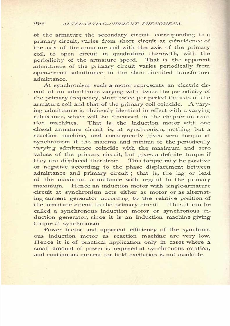
8/2/2019 Charles Steinmetz Theorycalculatio00steiiala
http://slidepdf.com/reader/full/charles-steinmetz-theorycalculatio00steiiala 318/557
292 ALTERNATING-CURRENT PHENOMENA.
of the armature the secondary circuit, corresponding to a
primary circuit, varies from short circuit at coincidence of
the axis of the armature coil with the axis of the primary
coil, to open circuit in quadrature therewith, with the
periodicity of the armature speed. That is, the apparent
admittance of the primary circuit varies periodically from
open-circuit admittance to the short-circuited transformer
admittance.
At synchronism such a motor represents an electric cir-
cuit of an admittance varying with twice the periodicity of
the primary frequency, since twice per period the axis of the
armature coil and that of the primary coil coincide. A vary-
ing admittance is obviously identical in effect with a varying
reluctance, which will be discussed in the chapter on reac-
tion machines. That is, the induction motor with one
closed armature circuit is, at synchronism, nothing but a
reaction machine, and consequently gives zero torque at
synchronism if the maxima and minima of the periodically
varying admittance coincide with the maximum and zero
values of the primary circuit, but gives a definite torque if
they are displaced therefrom. This torque may be positive
or negative according to the phase displacement betweenadmittance and primary circuit
;that is, the lag or lead
of the maximum admittance with regard to the primary
maximum. Hence an induction motor with single-armature
circuit at synchronism acts either as motor or as alternat-
ing-current generator according to the relative position of
the armature circuit to the primary circuit. Thus it can be
called a synchronous induction motor or synchronous in-
duction generator, since it is an induction machine giving
torque at synchronism.
Power factor and apparent efficiency of the synchron-
ous induction motor as reaction' machine are very low.
Hence it is of practical application only in cases where a
small amount of power is required at synchronous rotation,
and continuous current for field excitation is not available.

8/2/2019 Charles Steinmetz Theorycalculatio00steiiala
http://slidepdf.com/reader/full/charles-steinmetz-theorycalculatio00steiiala 319/557
INDUCTION MOTOR. 293
The current induced in the armature of the synchronous
induction motor is of double the frequency impressed upon
the primary.
Below and above synchronism theordinary induction
motor, or induction generator, torque is superimposed upon
the synchronous induction machine torque. Since with the
frequency of slip the relative position of primary and of
secondary coil changes, the synchronous induction machine
torque alternates periodically with the frequency of slip.
That is, upon the constant positive or negative torque be-
low or above synchronism an alternating torque of the fre-
quency of slip is superimposed, and thus the resultant
torque pulsating with a positive mean value below, a nega-
tive mean value above, synchronism.
Whenstarted
from rest,asynchronous
inductionmotor
will accelerate like an ordinary single-phase induction mo-
tor, but not only approach synchronism, as the latter does,
but run up to complete synchronism under load. When
approaching synchronism it makes definite beats with the
frequency ofslip, which disappear when synchronism is
reached.
THE HYSTERESIS MOTOR.181. In a revolving magnetic field, a circular iron disk,
or iron cylinder of uniform magnetic reluctance in the
direction of the revolving field, is set in rotation, even if
subdivided so as to preclude the induction of eddy currents.
This rotation is due to the effect of hysteresis of the revolv-
ing disks or cyclinder, and such a motor may thus be called
a hysteresis motor.
Let / be the iron disk exposed to a rotating magnetic
field or resultant M.M.F. The axis of resultant magneti-
zation in the disk / does not coincide with -the axis of the
rotating field, but lags behind the- latter, thus producing a
couple. That is, the component of magnetism in a direction
of therotating
disk, /, ahead of the axis of
rotatingM.M.F.,
is rising, thus below, and in a direction behind the axis

8/2/2019 Charles Steinmetz Theorycalculatio00steiiala
http://slidepdf.com/reader/full/charles-steinmetz-theorycalculatio00steiiala 320/557
294 ALTERNA TING-CURRENT PHENOMENA.
of rotating M.M.F. decreasing; that is, above proportion-
ality with the M.M.F., in consequence of the lag of magnet-
ism in the hysteresis loop, and thus the axis of resultant
magnetism in the iron disk, /, does not coincide with the
axis of rotating M.M.F., but is shifted backwards by an
angle, a, which is the angle of hysteretic lead in Chapter
X., 79.
The induced magnetism gives with the resultant M.M.F.
a mechanical couple,
T= mF& sin a,
where
F= resultant M.M.F.,
< = resultant magnetism,
a = angle of hysteretic advance of phase,
m = a constant.
The apparent or voltampere input of the motor is,
Q = mF.
Thus the apparent torque efficiency,
T
2
= sma,
and the power of the motor is,
P = (1 s) T= (1 s)m F<$> sin a,
where
s = slip as fraction of synchronism.
The apparent efficiency is,
P- = (!_*) sin a.
Since in a magnetic circuit containing an air gap the
angle a is extremely small, a- few degrees only, it follows
that the apparent efficiency of the hysteresis motor is ex-
tremelylow, the motor
consequentlyunsuitable for
produ-cing larger amounts of mechanical work.

8/2/2019 Charles Steinmetz Theorycalculatio00steiiala
http://slidepdf.com/reader/full/charles-steinmetz-theorycalculatio00steiiala 321/557
INDUCTION MOTOR. 295
From the equation of torque it follows, however, that at
constant impressed E.M.F., or current, that inconstant
F, the torque is constant and independent of the speed ;
and therefore such a motor arrangement is suitable, and
occasionally used as alternating-current meter.
The same result can be reached from a different point
of view. In such a magnetic system, comprising a mov-
able iron disk, /, of uniform magnetic reluctance in a
revolving field, the magnetic reluctance and thus the dis-
tribution of magnetism is obviously independent of the
speed, and consequently the current and energy expenditure
of the impressed M.M.F. independent of the speed also. If,
now,V'= volume of iron of the movable part,
B =magnetic density,
and77 = coefficient of hysteresis,
the energy expended by hysteresis in the movable disk, /, is
per cycle,
IV,= V^B,
hence, if N= frequency, the energy supplied by the M.M.F.
to the rotating iron disk in the hysteretic loop of the
M.M.F. is,
P =
At the slip, s N, that is, the speed (1 s) N, the energy
xpended by hysteresis in the rotating disk is, however,
Hence, in the transfer from the stationary to the revolv-
ing member the magnetic energy,
has disappeared, and thus reappears as mechanical work,
and the torque is,
'-p^iprW'that is, independent of the speed.

8/2/2019 Charles Steinmetz Theorycalculatio00steiiala
http://slidepdf.com/reader/full/charles-steinmetz-theorycalculatio00steiiala 322/557
296 ALTERNA TING-CURRENT PHENOMENA.
Since, as seen in Chapter X., sin a is the ratio of the
energy of the hysteretic loop to the total apparent energy,
in voltampere, of the magnetic cycle, it follows that the
apparent efficiency of such a motor can never exceed the
value (1 s)sin a, or a fraction of the primary hysteretic
energy.
The primary hysteretic energy of an induction motor, as
represented by its conductance, g, being a part of the loss
in the motor, and thus a very small part of its output only,
it follows that the output of a hysteresis motor is a very
small fraction only of the output which the same magnetic
structure could give with secondary short-circuited winding,
as regular induction motor.
As secondary effect, however, the rotary effort of the
magneticstructure as
hysteresismotor
appearsmore or less
in all induction motors, although usually it is so small as to
be neglected.
If in the hysteresis motor the rotary iron structure has
not uniform reluctance in all directions but is, for in-
stance, bar-shaped or shuttle-shaped on the hysteresis
motor effect is superimposed the effect of varying magnetic
reluctance, which tends to accelerate the motor to syn-
chronism, and maintain it therein, as shall be more fully
investigated under " Reaction Machine"
in Chapter XX.

8/2/2019 Charles Steinmetz Theorycalculatio00steiiala
http://slidepdf.com/reader/full/charles-steinmetz-theorycalculatio00steiiala 323/557
ALTERNATING-CURRENT GENERATOR. 297
CHAPTER XVII.
ALTERNATING-CURRENT GENERATOR.
182. In the alternating-current generator, E.M.F. is
induced in the armature conductors by their relative motion
through a constant or approximately constant magnetic
field.
When yielding current, two distinctly different M.M.Fs.
are acting upon the alternator armature the M.M.F. of
the field due to the field-exciting 'spools, and the M.M.F.of the armature current. The former is constant, or approx-
imately so, while the latter is alternating, and in synchro-
nous motion relatively to the former; hence, fixed in space
relative to the field M.M.F., or uni-directional, but pulsating
in a single-phase alternator. In the polyphase alternator,
when evenly loaded or balanced, the resultant M.M.F. of
the armature current is more or less constant.
The E.M.F. induced in the armature is due to the mag-
netic flux passing through and interlinked with the arma-
ture conductors. This flux is produced by the resultant of
both M.M.Fs., that of the field, and that of the armature.
On open circuit, the M.M.F. of the armature is zero, and
the E.M.F. of the armature is due to the M.M.F. of the
field coils only. In this case the E.M.F. is, in general, a
maximum at the moment when the armature coil faces the
position midway between adjacent field coils, as shown in
Fig. 126, and thus incloses no magnetism. The E.M.F.
wave in this case is, in general, symmetrical.
An exception from this statement may take place only
in thosetypes
of alternatorswhere
themagnetic
reluctance
of the armature is different in different directions; thereby,

8/2/2019 Charles Steinmetz Theorycalculatio00steiiala
http://slidepdf.com/reader/full/charles-steinmetz-theorycalculatio00steiiala 324/557
298 ALTERNA TING-CURRENT PHENOMENA.
during the synchronous rotation of the armature, a pulsa-
tion of the magnetic flux passing through it is produced.
This pulsation of the magnetic flux induces E.M.F. in the
field spools, and thereby makes the field current pulsating
also. Thus, we have t in this case, even on open circuit, no
Fig. 126.
rotation through a constant magnetic field, but rotation
through a pulsating field, which makes the E.M.F. wave
unsymmetrical, and shifts the maximum point from its the-
oretical position midway between the field poles. In gen-
eral this secondary reaction can be neglected, and the field
M.M.F. be assumed as constant.
The relative position of the armature M.M.F. with re-
spect to the field M.M.F. depends upon the phase rela-
tion existing in the electric circuit. Thus, if there is no
displacement of phase between current and E.M.F., the
current reaches its maximum at the same moment as the
E.M.F.; or, in the position of the armature shown in Fig.
126, midway between the field poles. In this case the arma-
ture current tends neither to magnetize nor demagnetize the
field, but merely distorts it;that is, demagnetizes the trail-
ing-pole corner, a, and magnetizes the leading-pole corner,
b. A change of the total flux, and thereby of the resultant
E.M.F., will take place in this case only when the magnetic
densities are so near to saturation that the rise of
densityat the leading-pole corner will be less than the decrease of
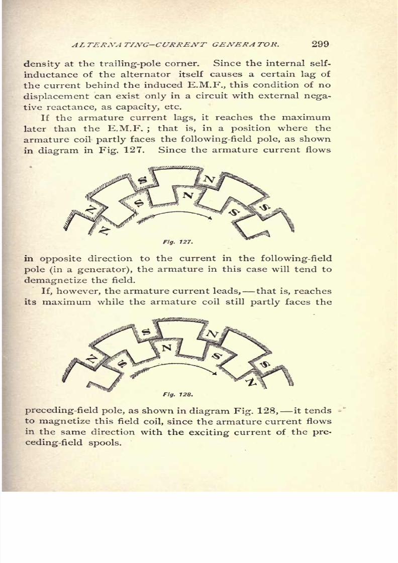
8/2/2019 Charles Steinmetz Theorycalculatio00steiiala
http://slidepdf.com/reader/full/charles-steinmetz-theorycalculatio00steiiala 325/557
AL TERNA TING-CURRENT GENERA TOR. 299
density at the trailing-pole corner. Since the internal self-
inductance of the alternator itself causes a certain lag of
the current behind the induced E.M.F., this condition of no
displacement can exist only in a circuit with external nega-
tive reactance, as capacity, etc.
If the armature current lags, it reaches the maximum
later than the E.M.F.;
that is, in a position where the
armature coil
partly
faces thefollowing-field
pole, as shown
in diagram in Fig. 127. Since the armature current flows
Fig. 127.
in opposite direction to the current in the following-field
pole (ina generator), the armature in this case will tend to
demagnetize the field.
If, however, the armature current leads, that is, reaches
its maximum while the armature coil still partly faces the
Fig. 128.
preceding-field pole, as shown in diagram Fig. 128, it tends
to magnetize this field coil, since the armature current flows
in
the same direction with the exciting current of the pre-
ceding-field spools.

8/2/2019 Charles Steinmetz Theorycalculatio00steiiala
http://slidepdf.com/reader/full/charles-steinmetz-theorycalculatio00steiiala 326/557
300 ALTERNA TING-CURRENT PHENOMENA.
Thus, with a leading current, the armature reaction of
the alternator strengthens the field, and thereby, at con-
stant-field excitation, increases the voltage ;with lagging
current it weakens the field, and thereby decreases the vol-
tage in a generator. Obviously, the opposite holds for a
synchronous motor, in which the armature current flows in
the opposite direction;and thus a lagging current tends to
magnetize, a leading current to demagnetize, the field.
183. The E.M.F. induced in the armature by the re-
sultant magnetic flux, produced by the resultant M.M.F. of
the field and of the armature, is not the terminal voltage
of the machine;the terminal voltage is the resultant of this
induced E.M.F. and the E.M.F. of self-inductance and the
E.M.F. representing the energy loss by resistance in the
alternator armature. That is, in other words, the armature
current not only opposes or assists the field M.M.F. in cre-
ating the resultant magnetic flux, but sends a second mag-
netic flux in a local circuit through the armature, which
flux does not pass through the field spools, and is called the
magnetic flux of armature self-inductance.
Thus we have to distinguish in an alternator betweenarmature reaction, or the magnetizing action of the arma-
ture upon the field, and armature self-inductance, or the
E.M.F. induced in the armature conductors by the current
flowing therein. This E.M.F. of self-inductance is(if
the
magnetic reluctance, and consequently the reactance, of
the armature circuit is assumed as constant) in quadrature
behind the armature current, and will thus combine with
the induced E.M.F. in the proper phase relation. Obvi-
ously the E.M.F. of self-inductance and the induced E.M.F.
do not in reality combine, but their respective magnetic
fluxes combine in the armature core, where they pass through
the same structure. These component E.M.Fs. are there-
fore mathematical fictions, but their resultant is real. This
means that, if the armature current lags, the E.M.F. of self-

8/2/2019 Charles Steinmetz Theorycalculatio00steiiala
http://slidepdf.com/reader/full/charles-steinmetz-theorycalculatio00steiiala 327/557
ALTERNATING-CURRENT GENERATOR. 301
inductance will be more than 90 behind the induced E.M.F.,
and therefore in partial opposition, and will tend to reduce
the terminal voltage. On the other hand, if the armature
current leads, the E.M.F. of self-inductance will be less
than 90 behind the induced E.M.F., or in partial conjunc-
tion therewith, and increase the terminal voltage. This
means that the E.M.F. of self-inductance increases the ter-
minal voltage with a leading, and decreases it with a lagging
current, or, in other words, acts in the same manner as the
armature reaction. For this reason both actions can be
combined in one, and represented by what is called the syn-
cJironous reactance of the alternator. In the following, we
shall represent the total reaction of the armature of the
alternator by the one term, synchronous reactance. While
this is notexact,
as statedabove,
since the reactance should
be resolved into the magnetic reaction due to the magnet-
izing action of the armature current, and the electric reac-
tion due to the self-induction of the armature current, it is
in general sufficiently near for practical purposes, and well
suited to explain the phenomena taking place under the
various conditions of load. This synchronous reactance, x,
Is frequently not constant, but is pulsating, owing to the
synchronously varying reluctance of the armature magnetic
circuit, and the field magnetic circuit;
it may, however, be
considered in what follows as constant;that is, the E.M.Fs.
induced thereby may be represented by their equivalent sine
waves. A specific discussion of the distortions of the wave
shape due to the pulsation of the synchronous reactance is
found in Chapter XX. The synchronous reactance, x, is
not a true reactance in the ordinary sense of the word, but
an equivalent or effective reactance. Sometimes the total
effects taking place in the alternator armature, are repre-
sented by a magnetic reaction, neglecting the self-inductance.'
altogether, or rather replacing it by an increase of the arma-
ture reaction or armature M.M.F. to such a value as to in-
clude the self-inductance. This assumption is mostly made
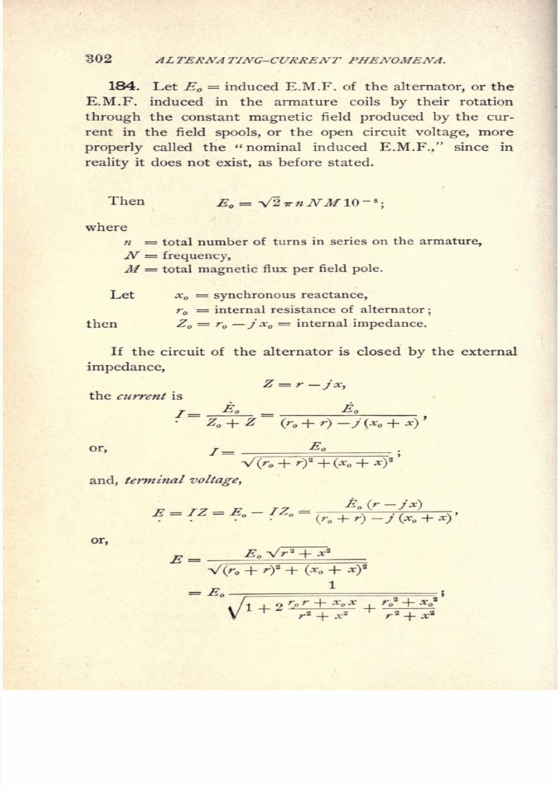
8/2/2019 Charles Steinmetz Theorycalculatio00steiiala
http://slidepdf.com/reader/full/charles-steinmetz-theorycalculatio00steiiala 328/557
"302 ALTERNATING-CURRENT PHENOMENA.
184. Let E = induced E.M.F. of the alternator, or the
E.M.F. induced in the armature coils by their rotation
through the constant magnetic field produced by the cur-
rent in the field spools, or the open circuit voltage, more
properly called the "nominal induced E.M.F.," since in
reality it does not exist, as before stated.
Then E
where
n = total number of turns in series on the armature,
JV = frequency,
M = total magnetic flux per field pole.
Let x =synchronous reactance,
r = internal resistance of alternator;
then Z r j x = internal impedance.
If the circuit of the alternator is closed by the external
impedance,
Z = r-jx,the current is
E E
or, /=
and, terminal voltage,
or,
+x-

8/2/2019 Charles Steinmetz Theorycalculatio00steiiala
http://slidepdf.com/reader/full/charles-steinmetz-theorycalculatio00steiiala 329/557
ALTERNA TING-CURRENT GENERA TOR. 303
or, expanded in a series,
As shown, the terminal voltage varies with the condi-
tions of the external circuit.
185. As an instance, in Figs. 129-134, at constant
induced E.M.F.,Eo = 2500
;
Fig. 129. Field Characteristic of Alternator on Non-inductive Load.
'
+
and the values of the internal impedance,
z = r -j Xo = i - ioy.
With the current / as abscissae, the terminal voltages E

8/2/2019 Charles Steinmetz Theorycalculatio00steiiala
http://slidepdf.com/reader/full/charles-steinmetz-theorycalculatio00steiiala 330/557
304 AL TEKNA TING-CURRENT PHENOMENA.
dotted lines, we have, for the following conditions of external
circuit :
In Fig. 129, non-inductive external circuit, x = 0.
In Fig. 130, inductive external circuit, of the condition, r / x
= -f .75, with a power factor, .6.
InFig. 131, inductive external circuit, of the condition, r= <>,
with a power factor, 0.
In Fig. 132, external circuit with leading current, of the condi-
tion, r/x = .75, with a power factor, .6.
In Fig. 133, external circuit with leading current, of the condi-
tion, r = 0, with a power factor, 0.
In Fig. 134, all the volt-ampere curves are shown together as
complete ellipses, giving also the negative or synchronous
motor part of the curves.
Fig. 130. Field Characteristic of Alternator, at 60% Power-factor on Inductive Load.
Such a curve is called a field characteristic.
As shown, the E.M.F. curve at non-inductive load is
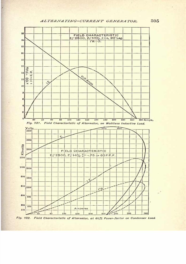
8/2/2019 Charles Steinmetz Theorycalculatio00steiiala
http://slidepdf.com/reader/full/charles-steinmetz-theorycalculatio00steiiala 331/557
ALTERNATING-CURRENT GENERATOR. 305
Fig. 131. Field Characteristic of Alternator, on Wattless Inductive Load.

8/2/2019 Charles Steinmetz Theorycalculatio00steiiala
http://slidepdf.com/reader/full/charles-steinmetz-theorycalculatio00steiiala 332/557
306 ALTERNA TING-CURRENT PHENOMENA.
fig. 133. Field Characteristic of Alternator, on Wattless Condenser Load.
With reactive load the curves are more nearly straight
lines.
The voltage drops on inductive, rises on capacity load.
The output increases from zero at open circuit to a maxi-
mum, and then decreases again to zero at short circuit.
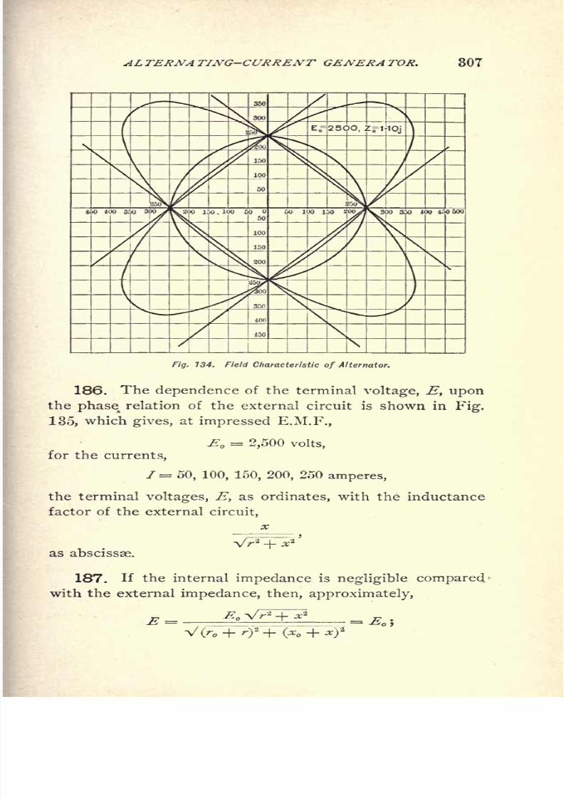
8/2/2019 Charles Steinmetz Theorycalculatio00steiiala
http://slidepdf.com/reader/full/charles-steinmetz-theorycalculatio00steiiala 333/557
ALTERNA TING-CURRENT GENERA TOR. 307
MK
4^z
W
Fig. 134. Field Characteristic of Alternator.
186. The dependence of the terminal voltage, E, upon
thephase
relation ofthe
externalcircuit
is
shown in Fig.
135, which gives, at impressed E.M.F.,
E = 2,500 volts,
for the currents,
1= 50, 100, 150, 200, 250 amperes,
the terminal voltages, E, as ordinates, with the inductance
factor of the external circuit,
as abscissas.
187. If the internal impedance is negligible compared
with the external impedance, then, approximately,

8/2/2019 Charles Steinmetz Theorycalculatio00steiiala
http://slidepdf.com/reader/full/charles-steinmetz-theorycalculatio00steiiala 334/557
308 AL TERNA TING-CURRENT PHENOMENA,
'
.C .5 .4 .3 .2 .1 -.1 -.2 -.3 -.1 -.5 -.0 -.7 -.8
Fig. 135. Regulation of Alternator on Various Loads.
that is, an alternator with small internal resistance and syn-
chronous reactance tends to regulate for constant terminal
voltage.
Every alternator does this near open circuit, especially
on non-inductive load.
Even if the synchronous reactance, x ,is not quite neg-
ligible, this regulation takes place, to a certain extent, on
non-inductive circuit, since for
* = 0, E
and thus the expression of the terminal voltage, E, contains
the synchronous reactance, x, only as a term of second
order in the denominator.
On inductive circuit, however, x appears in the denom-
inatoras a term of first
order,and therefore constant poten-
tial regulation does not take place as well.
8/2/2019 Charles Steinmetz Theorycalculatio00steiiala
http://slidepdf.com/reader/full/charles-steinmetz-theorycalculatio00steiiala 335/557
ALTERNATING-CURRENT GENERATOR. 309
With a non-inductive external circuit, if the synchronous
reactance, XQ ,of the alternator is very large compared with
the external resistance, r,
current /=x
-g. 1 _E,
approximately, or constant; or, if the external circuit con-
tains the reactance, x,
T=-**1 - *
approximately, or constant.
The terminal voltage of a non-inductive circuit is
approximately, or proportional to the external resistance.
In an inductive circuit,
x
approximately, or proportionalto
theexternal
impedance.
188. That is, on a non-inductive external circuit, an
alternator with very low synchronous reactance regulates
for constant terminal voltage, as a constant-potential ma-
chine;an alternator with a very high synchronous reac-
tance regulates for a terminal voltage proportional to the
external resistance, as a constant-current machine.Thus, every alternator acts as a constant-potential ma-
chine near open circuit, and as a constant-current machine
near short circuit. Between these conditions, there is a
range where the alternator regulates approximately as a
constant power machine, that is current and E.M.F. vary
in inverse proportion, as between 130 and 200 amperes in
Fig. 129.
8/2/2019 Charles Steinmetz Theorycalculatio00steiiala
http://slidepdf.com/reader/full/charles-steinmetz-theorycalculatio00steiiala 336/557
310 ALTERNATING-CURRENT PHENOMENA.
chines of the first class;the old alternators, as built by
Jablockkoff, Gramme, etc., were machines of the second
class, used for arc lighting, where constant-current regula-
tion is an advantage.
Obviously, large external reactances cause the same reg-
ulation for constant current independently of the resistance,
r, as a large internal reactance, .r .
On non-inductive circuit, if
theoutputis
hence, if
or
thendr
That is, the
poweris a
maximum,and
and 7 =
V2 So {so + r )
Therefore, with an external resistance equal to the inter-
nal impedance, or, r ^ = VV 2 + x^ ,the output of an
alternator is a maximum, and near this point it regulates
for constant output ;that is, an mcrease of current causes
a proportional decrease of terminal voltage, and inversely.
The field characteristic of the alternator shows this
effectplainly.

8/2/2019 Charles Steinmetz Theorycalculatio00steiiala
http://slidepdf.com/reader/full/charles-steinmetz-theorycalculatio00steiiala 337/557
SYNCHRONIZING ALTERNATORS. 311
CHAPTER XVIII.
SYNCHRONIZING ALTERNATORS.
189. All alternators, when brought to synchronism with
each other, will operate in parallel more or less satisfactorily.
This is due to the reversibility of the alternating-current
machine;that is, its ability to operate as synchronous motor.
In consequence thereof, if the driving power of one of sev-
eral parallel-operating generators is withdrawn, this gene-
rator will keep revolving in synchronism as a synchronous
motor;and the power with which it tends to remain in
synchronism is the maximum power which it can furnish
as synchronous motor under the conditions of running.
190. The principal and foremost condition of parallel
operation of alternators is equality of frequency ;that is,
the transmission of power from the prime movers to thealternators must be such as to allow them to run at the
same frequency without slippage or excessive strains on
the belts or transmission devices.
Rigid mechanical connection of the alternators cannot be
considered as synchronizing ;since it allows no flexibility or
phase adjustment between the alternators, but makes them
essentially one machine. If connected in parallel, a differ-
ence in the field excitation, and thus the induced E.M.F. of
the machines, must cause large cross-current;since it cannot
be taken care of by phase adjustment of the machines.
Thus rigid mechanical connection is not desirable for
parallel operation of alternators.
191. The second important condition of parallel opera-
tion is of that of
8/2/2019 Charles Steinmetz Theorycalculatio00steiiala
http://slidepdf.com/reader/full/charles-steinmetz-theorycalculatio00steiiala 338/557
312 ALTERNATING-CURRENT PHENOMENA.
If, for instance, two alternators are driven by independent
single-cylinder engines, and the cranks of the engines hap-
pen to be crossed, the one engine will pull, while the other
is near the dead-point, and conversely. Consequently, alter-
nately the one alternator will tend to speed up and the
other slow down, then the other speed up and the first
slow down. This effect, if not taken care of by fly-wheel
capacity, causes a "hunting" or pumping action; that is, a
fluctuation of the lights with the period of the engine revo-
lution, due to the alternating transfer of the load from one
engine to the other, which may even become so excessive
as to throw the machines out of step, especially when by an
approximate coincidence of the period of engine impulses
(or a multiple thereof), with the natural period of oscillation
of the revolving structure, theeffect is
madecumulative.
Thisdifficulty as a rule does not exist with turbine or water-
wheel driving.
192. In synchronizing alternators, we have to distin-
guish the phenomena taking place when throwing the ma-
chines in parallel or out of parallel, and the phenomena
when running in synchronism.
When connecting alternators in parallel, they are first
brought approximately to the same frequency and same
voltage ;and then, at the moment of approximate equality
of phase, as shown by a phase-lamp or other device, they
are thrown in parallel.
Equality of voltage is much less important with modern
alternators than equality of frequency, and equality of phase
is usually of importance only in avoiding an instantaneous
flickering of the lights on the system. When two alter-
nators are thrown together, currents pass between the
machines, which accelerate the one and retard the other
machine until equal frequency and proper phase relation
are reached.
With modern ironclad alternators, this interchange of
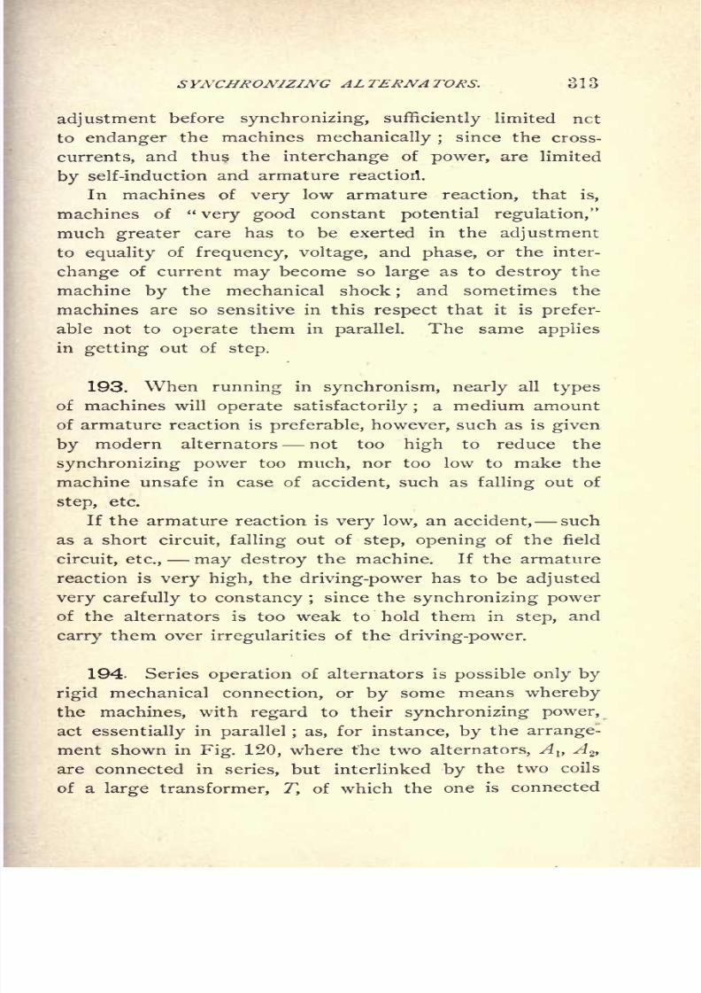
8/2/2019 Charles Steinmetz Theorycalculatio00steiiala
http://slidepdf.com/reader/full/charles-steinmetz-theorycalculatio00steiiala 339/557
SYNCHRONIZING ALTERNATORS. 313
adjustmentbefore
synchronizing, sufficientlylimited net
to endanger the machines mechanically ;since the cross-
currents, and thus the interchange of power, are limited
by self-induction and armature reaction .
In machines of very low armature reaction, that is,
machines of "very good constant potential regulation,"
much greater care has to be exerted in the adjustment
to equality of frequency, voltage, and phase, or the inter-
change of current may become so large as to destroy the
machine by the mechanical shock;
and sometimes the
machines are so sensitive in this respect that it is prefer-
able not to operate them in parallel. The same applies
in getting out of step.
193. When running in synchronism, nearly all types
of machines will operate satisfactorily ;a medium amount
of armature reaction is preferable, however, such as is given
by modern alternators not too high to reduce the
synchronizing power too much, nor too low to make the
machine unsafe in case of accident, such as falling out of
step, etc.
If the armature reaction is very low, an accident, such
as a short circuit, falling out of step, opening of the field
circuit, etc., may destroy the machine. If the armature
reaction is very high, the driving-power has to be adjusted
very carefully to constancy ;since the synchronizing power
of the alternators is too weak to hold them in step, and
carry them over irregularities of the driving-power.
194. Series operation of alternators is possible only by
rigid mechanical connection, or by some means whereby
the machines, with regard to their synchronizing power,
act essentially in parallel ; as, for instance, by the arrange-
ment shown in Fig. 120, where the two alternators, A l}A
2 ,
are connected in series, but interlinked by the two coils
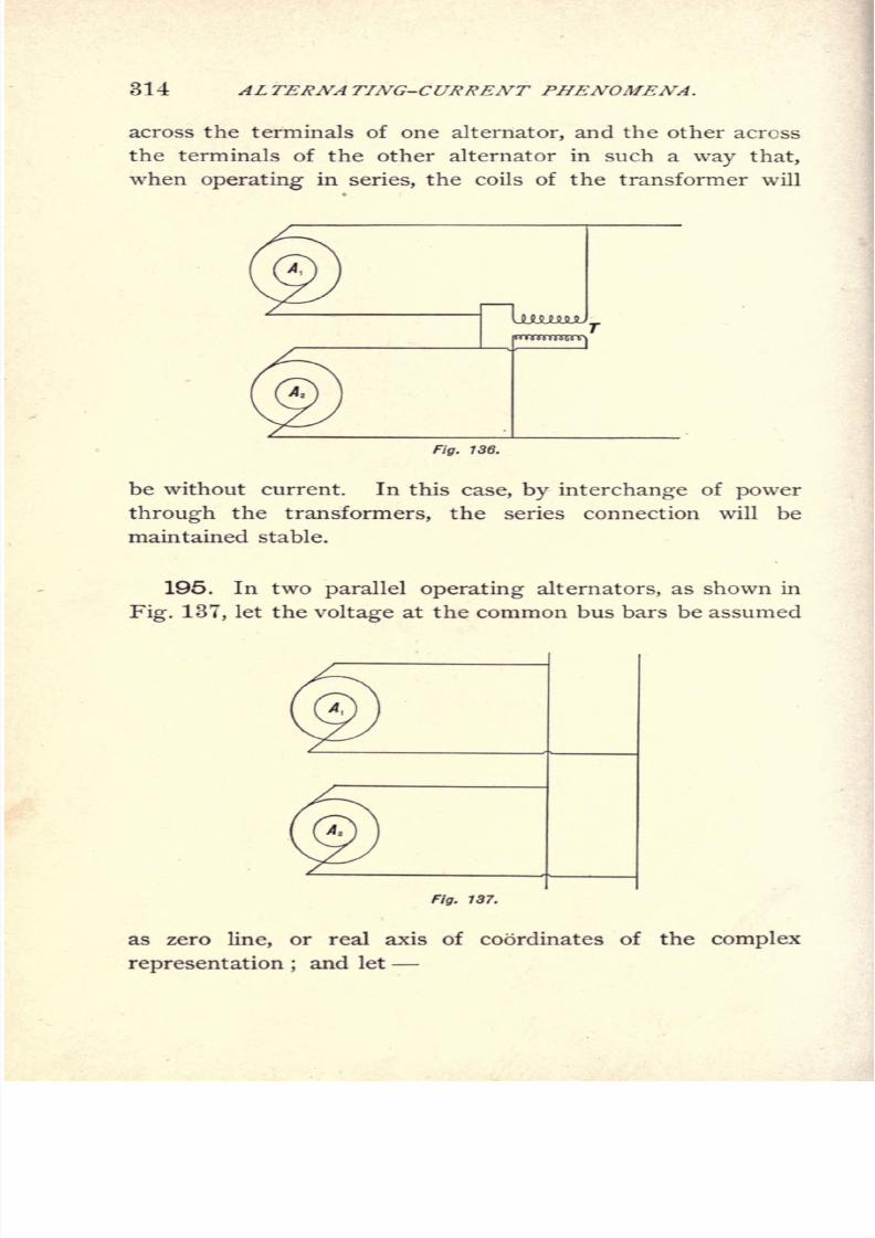
8/2/2019 Charles Steinmetz Theorycalculatio00steiiala
http://slidepdf.com/reader/full/charles-steinmetz-theorycalculatio00steiiala 340/557
314 AL TERNA TING-CURRENT PHENOMENA.
across the terminals of one alternator, and the other across
the terminals of the other alternator in such a way that,
when operating in series, the coils of the transformer will
Fig. 136.
be without current. In this case, by interchange of power
through the transformers, the series connection will be
maintained stable.
195. In two parallel operating alternators, as shown in
Fig. 137, let the voltage at the common bus bars be assumed
Fig. 137.
as zero line, or real axis of coordinates of the complex
representation ;and let

8/2/2019 Charles Steinmetz Theorycalculatio00steiiala
http://slidepdf.com/reader/full/charles-steinmetz-theorycalculatio00steiiala 341/557
SYNCHRONIZING ALTERNATORS. 315
e = difference of potential at the common bus bars of
the two alternators,
Z = r jx = impedance of external circuit,
Y= g -\-jb= admittance of external circuit
;
hence, the current in external circuit is
Let
J?i=
e-i je\= #2 (cos u>
1 j sin>i)= induced E.M.F. of first
machine;
2= e.2 _/>/
= a2 (cos w2 j sin w2)= induced E.M.F. of sec-
ond machine;
/! =/! -f-//i'
= current of first machine;
/2= /2 -j-yY2
' = current of second machine;
Z^ = T! jxi = internal
impedance,and Yv
=gi
-\-
jbl= inter-
nal admittance, of first machine;
Z2= r2 jxz
= internal impedance, and K2 =gz ~\~ jb<i= inter-
nal admittance, of second machine.
Then,
i^! , or ^ je^= (e
2Z2 ,or <?2 jej= (e
72 ,or
This gives the equations
4*+ *"-**;
or eight equations with nine variables: ^, ^', ^2 , ^/, /
lf
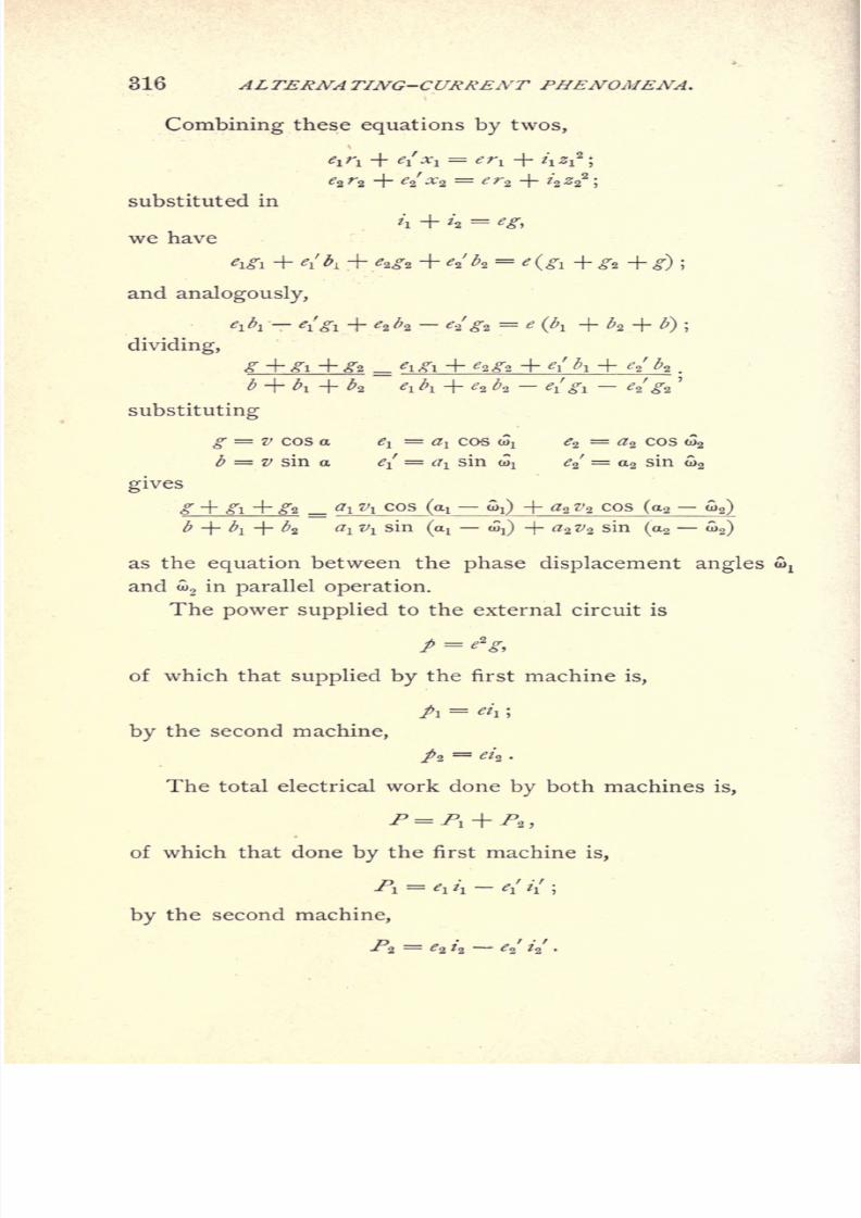
8/2/2019 Charles Steinmetz Theorycalculatio00steiiala
http://slidepdf.com/reader/full/charles-steinmetz-theorycalculatio00steiiala 342/557
316 ALTERNATING-CURRENT PHENOMENA.
Combining these equations by twos,
el rl -f eSxj. = er^ + t\ 2l2 -
e*r9 + ^/^2 = e
substituted in
'i + H =we have
and analogously,
'1^1 ^iVi + 'a *a <?aVa = ' (^ + ^2 +dividing,
b + ^i + ^2 ^i;̂i + <?a ^ ^iVi ^a' ^2
'
substituting
g = V COS a Cl=
tfj COS Wj 2̂= ^2 COS d)2
^ = z/ sin a^/
=^
sinoJj
^2
' = a2
sin <o
2
gives
a\ v\ cos (en aQ + a2 z>2 cos (a2 a2)
tfj z/! sin(ai w^) -\- a^Vs sin (a2
a>2)
as the equation between the phase displacement angles
and oi2in parallel operation.
The power supplied to the external circuit is
of which that supplied by the first machine is,
/i=
\ ;
by the second machine,
/2=
a
The total electrical work done by both machines is,
P = Pl + P*,
of. which that done by the first machine is,
PI = '! h - e,' // ;
by the second machine,
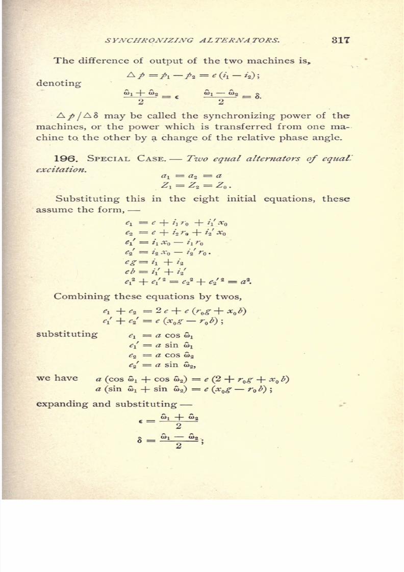
8/2/2019 Charles Steinmetz Theorycalculatio00steiiala
http://slidepdf.com/reader/full/charles-steinmetz-theorycalculatio00steiiala 343/557
SYNCHRONIZING ALTERNATORS. . 317
The difference of output of the two machines is,
denoting
>! -f- 0)2 <QI o>2 s
~2~ ~2~
A^>/AS may be called the synchronizing power of the
machines, or the power which is transferred from one ma-
chine to. the other by a change of the relative phase angle.
196. SPECIAL CASE. Two equal alternators of equaL
excitation.
Substituting this in the eight initial equations, these
assume the form,
e- = t x t r
e2' = /2 .r // r .
*g=i\ +'a
eb = i{ + /a
'
4* + 4" -</+ *"-<
Combining these equations by twos,
substituting el= a cos o^
e{ = a sin o^
^2= a cos 0)2
e2
f = a sin o)
2 ,
we have a (cos wx + cos wa)
= * (2 + r ^ +a (sin Si + sin w2)
= e (x^g rli)
expanding and substituting
8 =
8/2/2019 Charles Steinmetz Theorycalculatio00steiiala
http://slidepdf.com/reader/full/charles-steinmetz-theorycalculatio00steiiala 344/557
318 ALTERNA TING-CURRENT PHENOMENA.
a cos e cos 8 = e(1 +
rQg -\-Xzb
a sin e cos 8 = ^^ ^
hence
That is
-and cos 8 = -
tan e = ^ ^ = constant.
+ A2= constant;
-M1*5zaiy,
/^o^-^o^\
2
.
cos 8
at no-phase displacement between the alternators, or,
-we have e = ^.
V/('
+ n>^ + -*o^\2
, fxn r*b
From the eight initial equations we get, by combina-
(''o
2
subtracted and expanded
.or, since
<?!
<?
2
= ^(cos wj
cos G2)
= 2 tf2sin c sin 8
^/ <?/= a (sin wx sin w2)
= 2 a cos e sin 8;
we have
2 a s *n 8 - r sin c}
2 ay sin 8 cos(c -f a),
where
tan d = 2-.
/"o

8/2/2019 Charles Steinmetz Theorycalculatio00steiiala
http://slidepdf.com/reader/full/charles-steinmetz-theorycalculatio00steiiala 345/557
SYNCHRONIZING ALTERNATORS. 319
The difference of output of the two alternators is
A/ =/! / 2 = e(/i
/2) ;
hence, substituting,
substituting,
2ggsin8{jfrcos
- r sin c};
,
H
XQ r*b
2
i 'of, T *<)"
\ i
2 J
+V 2
we have,
2a2sin 8 cos 8
j*
(1 +
r *+ x *\ r
expanding,
A / = nr
Hence, the transfer of power between the alternators,
A ptis a maximum, if 8 = 45
;or Wj
w2= 90
;that is,
when the alternators are in quadrature.

8/2/2019 Charles Steinmetz Theorycalculatio00steiiala
http://slidepdf.com/reader/full/charles-steinmetz-theorycalculatio00steiiala 346/557
320 ALTERNATING-CURRENT PHENOMENA.
The synchronizing power, A p /A
8, is a maximum if
8 = ; that is, the alternators are in phase with each other.
197. As an instance, curves may be plotted
for,
a =2500,
with the angle 8 =U)l a>2 as abscissae, giving
the value of terminal voltage, e
the value of current in the external circuit, / = ey ;
the value of interchange of current between the alternators,
*i-*2 ;
the value of interchange of power between the alternators, A p=A-/2 ;
the value of synchronizing power, ^ .
A o
For the condition of external circuit,
g = 0, b = 0, y = 0,
.05, 0, .05,
.08, 0, .08,
.03, + .04, .05,
.03,-
.04, .05.

8/2/2019 Charles Steinmetz Theorycalculatio00steiiala
http://slidepdf.com/reader/full/charles-steinmetz-theorycalculatio00steiiala 347/557
SYNCHRONOUS MOTOR. 321
CHAPTER XIX.
SYNCHRONOUS MOTOR.
198. In the chapter on synchronizing alternators we
have seen that when an alternator running in synchronism
is connected with a system of given E.M.F., the work done
by the alternator can be either positive or negative. In
the latter case the alternator consumes electrical, and
consequently produces mechanical, power ;that is, runs
as a synchronous motor, so that the investigationof the
synchronous motor is already contained essentially in the
equations of parallel-running alternators.
Since in the foregoing we have made use mostly of
the symbolic method, we may in the following, as an
instance of the graphical method, treat the action of the
synchronous motor diagrammatically.
Let an alternator of the E.M.F., E, be connected as
synchronous motor with a supply circuit of E.M.F., EQ ,
by a circuit of the impedance Z.
If E is the E.M.F. impressed upon the motor termi-
nals, Z is the impedance of the motor of induced E.M.F.,
E. If E is the E.M.F. at the generator terminals, Z is
the impedance of motor and line, including transformers
and other intermediate apparatus. If EQis the induced
E.M.F. of the generator, Z is the sum of the impedances
of motor, line, and generator, and thus we have the prob-
lem, generator of induced E.M.F. EQ ,
and motor of induced'
E.M.F. El ; or, more general, two alternators of induced
E.M.Fs., E ,E
lfconnected together into a circuit of total
impedance,Z.
Since in this case several E.M.Fs. are acting in circuit

8/2/2019 Charles Steinmetz Theorycalculatio00steiiala
http://slidepdf.com/reader/full/charles-steinmetz-theorycalculatio00steiiala 348/557
322 ALTERNATING-CURRENT PHENOMENA.
with the same current, it is convenient to use the current,
/, as zero line OI of the polar diagram. Fig. 188.
If I=i= current, and Z = impedance, r = effective
resistance, x = effective reactance, and s = Vr2-f x
2 =
absolute value of impedance, then the E.M.F. consumed
by the resistance is E,, = ri, and in phase with the cur-
rent, hence represented by vector OE,, ;and the E.M.F.
consumedby
the reactance is E2
=xi,
and 90 ahead of
the current, hence the E.M.F. consumed by the impedance
is E = V(,,)2 + (E 2f, or = i Vr2 + x* = is, and ahead of
the current by the angle 8, where tan 8 = x/ r.
We have now acting in circuit the E.M.Fs., E, ElfE
Q ;
or Eland E are components of E
Q ;that is, EQ
is the
diagonal of a parallelogram, with Eland E as sides.
Since the E.M.Fs. Elf
Ez , E, are represented in the
diagram, Fig. 138, by the vectors OE~lf OE2 , OE, to get
the parallelogram ofQ ,E
lt E, we draw arcs of circles
around with EQ ,
and around E with El
. Their point of
intersection gives the impressed E.M.F., OEQ= E
Q ,and
completing the parallelogram OE EQE we get, OE = E
,
the induced E.M.F. of the motor.
IOE is the difference of phase between current and im-
pressed E.M.F., or induced E.M.F. of the generator.
IOEi is the difference of phase between current and in-
duced E.M.F. of the motor.
And the power is the current /times the projection of the E.M.F.
upon the current, or the zero line OI.
Hence, dropping perpendiculars, E^EJ and E^E^, from
EQand E! upon OI, it is
P = iX OE^ = power supplied by induced E.M.F. of gen-
erator.
PI = / X OE^ = electric power transformed in mechanical
power by the motor.
P = / x OEl = power consumed in the circuit by effective
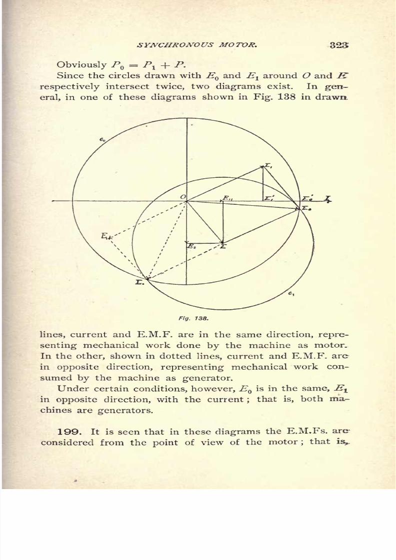
8/2/2019 Charles Steinmetz Theorycalculatio00steiiala
http://slidepdf.com/reader/full/charles-steinmetz-theorycalculatio00steiiala 349/557
SYNCHRONOUS MOTOR. 323
Since the circles drawn with EQand E around O and K
respectively intersect twice, two diagrams exist. In gen-
eral, in one of these diagrams shown in Fig. 138 in drawn
Fig. 138.
lines, current and E.M.F. are in the same direction, repre-
senting mechanical work done by the machine as motor-
In theother,
shown in dottedlines,
current and E.M.F. are
in opposite direction, representing mechanical work con-
sumed by the machine as generator.
Under certain conditions, however, Qis in the same, E^
in opposite direction, with the current;
that is, both ma-
chines are generators.
199. It is seen that in these diagrams the E.M.Fs. are-
considered from the of view of the motor that is,.

8/2/2019 Charles Steinmetz Theorycalculatio00steiiala
http://slidepdf.com/reader/full/charles-steinmetz-theorycalculatio00steiiala 350/557
324 ALTERNATING-CURRENT PHENOMENA.
work done as synchronous motor is considered as positive,
work done as generator is negative. In the chapter on syn-
chronizing generators we took the opposite view, from the
generator side.
In a single unit-power transmission, that is, one generator
supplying one synchronous motor over a line, the E.M.F.
consumed by the impedance, E = OE, Figs. 139 to 141, con-
sists of three components ;the E.M.F. OE E
z ,consumed
Fig. 139.
by the impedance of the motor, the E.M.F.
consumed by the impedance of the line, and the E.M.F.
EZ E = E consumed by the impedance of the generator.
Hence, dividing the opposite side of the parallelogram E1E
(),
in the same way, we have : OEl= E
1= induced E.M.F. of
the motor, OEZ= 2?
a= E.M.F. at motor terminals or at
end of line, OE3= E
3= E.M.F. at generator terminals,
or at
beginningof line.
OEQ
=EQ
= induced E.M.F. of
generator.

8/2/2019 Charles Steinmetz Theorycalculatio00steiiala
http://slidepdf.com/reader/full/charles-steinmetz-theorycalculatio00steiiala 351/557
SYNCHRONOUS MOTOR. 325
The phase relation of the current with the E.M.Fs.lt
, depends upon the current strength and the E.M.Fs. El
and
200. Figs. 139 to 141 show several such diagrams for
different values of Elf
but the same value of / and EQ
.
The motor diagram being given in drawn line, the genera-
tor diagram in dotted line.
Fig. 140.
As seen, for small values of E1the potential drops in
the alternator and in the line. For the value of E1= E
the potential rises in the generator, drops in the line, and
rises again in the motor. For larger values of Ely
thfe
potential rises in the alternator as well as in the line, so
that the highest potential is the induced E.M.F. of the
motor, the lowestpotential
the induced E.M.F. of thegen-
erator.
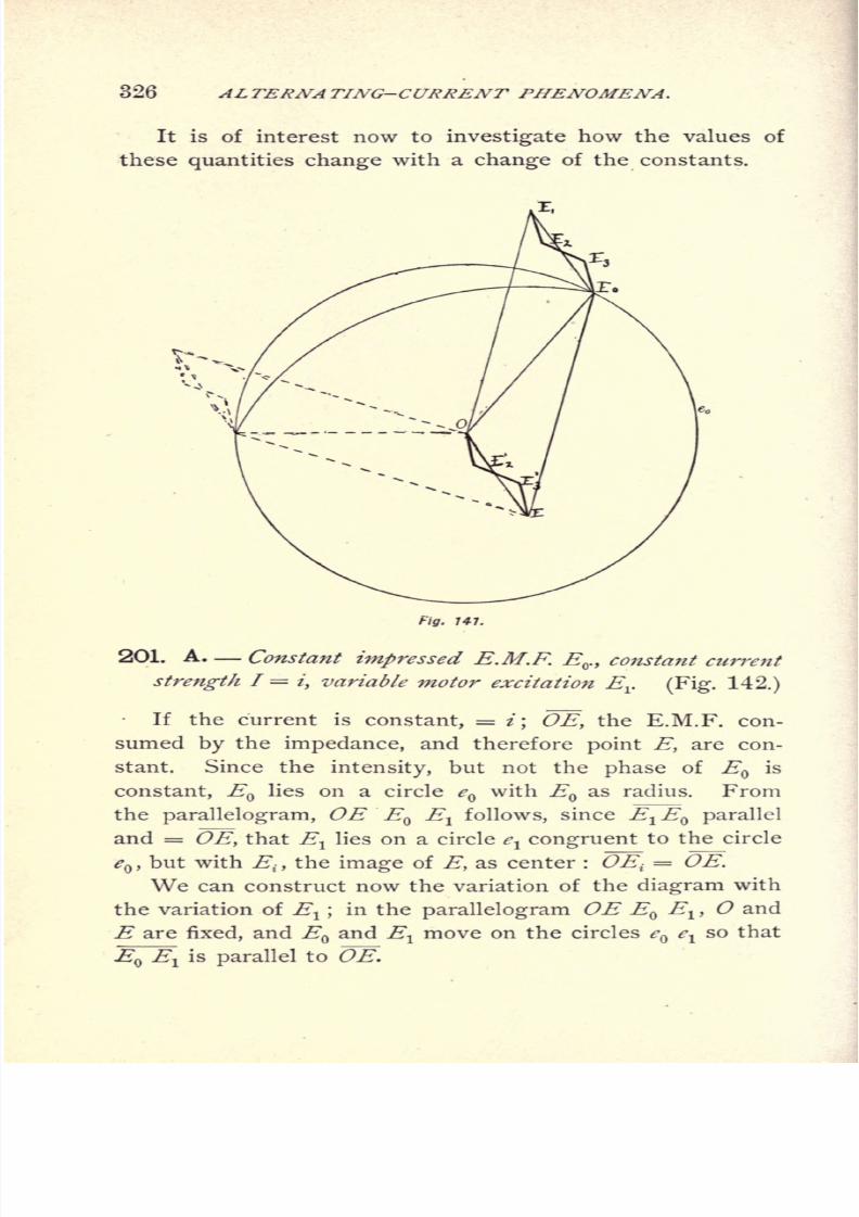
8/2/2019 Charles Steinmetz Theorycalculatio00steiiala
http://slidepdf.com/reader/full/charles-steinmetz-theorycalculatio00steiiala 352/557
326 ALTERNATING-CURRENT PHENOMENA,
It is of interest now to investigate how the values of
these quantities change with a change of the constants.
Fig.747.
201. A. Constant impressed E.M.F. Ev , constant current
strength I =i, variable motor excitation Ev (Fig. 142.)
If the current is constant, = z; OE, the E.M.F. con-
sumed by the impedance, and therefore point E, are con-
stant. Since the intensity, but not the phase of EQ
is
constant, EQlies on a circle e
Qwith EQ
as radius. From
the parallelogram, OE EQE
l follows, since E1E
Q parallel
and = OE, that Ellies on a circle e
l congruent to the circle
eQ ,
but with Ei}
the image of E, as center : OEi= OE.
We can construct now the variation of the diagram with
the variation of El ;
in the parallelogram OE EQE
1 ,O and
Eare
fixed, and E and El move
on the circles <? el
so that
EQ E^ is parallel to OE.

8/2/2019 Charles Steinmetz Theorycalculatio00steiiala
http://slidepdf.com/reader/full/charles-steinmetz-theorycalculatio00steiiala 353/557
SYNCHRONOUS MOTOR. 327
The smallest value of Elconsistent with current
strength/ is Olj = E^, 01 = EQ. In this case the power of the
motor is Olj1 x /, hence already considerable. Increasing
Elto 02"^ OSj, etc., the impressed E.M.Fs. move to 02, 03,
etc., the power is / x 02^, I x 03^, etc., increases first,
Fig. 142.
reaches the maximum at the point 3j, 3, the most extreme
point at the right, with the impressed E.M.F. in phase with
the current, and then decreases again, while the induced
E.M.F. of the motor E^ increases and becomes =Q
at
4,, 4. At 5 15 5, the power becomes zero, and further ona and

8/2/2019 Charles Steinmetz Theorycalculatio00steiiala
http://slidepdf.com/reader/full/charles-steinmetz-theorycalculatio00steiiala 354/557
328 ALTERNATING-CURRENT PHENOMENA.
produces electrical energy, while the impressed E.M.F. E^
still furnishes electrical energy, that is, both machines as
generators feed into the line, until at 6 1} 6, the power of the
impressed E.M.F. E becomes zero, and further on power
begins to flow back;that is, the motor is changed to a gen-
erator and the generator to a motor, and we are on the
generator side of the diagram. At 1l , 7, the maximum value
of Elt
consistent with the current /, has been reached, and
passing still further the E.M.F. Eldecreases again, while
the power still increases up to the maximum at Slt 8, and
then decreases again, but still El remaining generator, EQ
motor, until at 11^ 11, the power of EQbecomes zero; that
is, EQ changes again to a generator, and both machines are
generators, up to 12lf 12, where the power of E
lis zero, El
changesfrom
generatorto
motor,and we come
againto
the motor side of the diagram, and while Elstill decreases,
the power of the motor increases until lu 1, is reached.
Hence, there are two regions, for very large Elfrom
5 to 6, and for very small Elfrom 11 to 12, where both
machines are generators ;otherwise the one is generator,
the other motor.
For small values of El the current is lagging, begins,
however, at 2 to lead the induced E.M.F. of the motor Elf
at 3 the induced E.M.F. of the generator E .
It is of interest to note that at the smallest possible
value of EI} lj,
the power is already considerable. Hence,
the motor can run under these conditions only at a certain
load. If this load is thrown off, the motor cannot run with
the same current, but the current must increase. We have
here the curious condition that loading the motor reduces,
unloading increases, the current within the range between
1 and 12.
The condition of maximum output is 3, current in phase
with impressed E.M.F. Since at constant current the loss
is constant, this is at the same time the condition of max-
imum efficiency : no displacement of phase of the impressed

8/2/2019 Charles Steinmetz Theorycalculatio00steiiala
http://slidepdf.com/reader/full/charles-steinmetz-theorycalculatio00steiiala 355/557
SYNCHRONOUS MOTOR. 329
E.M.F., or self-induction of the circuit compensated by the
effect of the lead of the motor current. This condition of
maximum efficiency of a circuit we have foundalready in
the Chapter on Inductance and Capacity.
202. B. EQand E
l constant, I variable.
Obviously EQlies
againon the circle e
Qwith
EQ as radiusand O as center.
Fig. 143.
E lies on a straight line e, passing throtigh the origin;
Since in the parallelogram OE E Ev EEQ= E^ we
derive EQ by laying a line EE
Q= E from any point E
in the circle eQ ,
and complete the parallelogram.All these lines EE a certain curve e which

8/2/2019 Charles Steinmetz Theorycalculatio00steiiala
http://slidepdf.com/reader/full/charles-steinmetz-theorycalculatio00steiiala 356/557
030 ALTERNATING-CURRENT PHENOMENA.
can be considered as the characteristic curve of this prob-
lem, just as circle e^ in the former problem.
These curves are drawn in Figs. 143, 144, 145, for the
three cases : 1st, El= E
Q ; 2d, El< EQ ; 3d, 1
>Q
.
In the first case, El= E
Q (Fig. 127), we see that at
Fig. 144.
very small current, that is very small OE, the current /
leads the impressed E.M.F. EQ by an angle EQ
Of = WQ
.
This lead decreases with increasing current, becomes zero,
and afterwards for larger current, the current lags. Taking
now any pair of corresponding points E, EQ ,and producing
EEQ
until it intersects eit
in
Eif
we have
^^ Ei
OE 90,El= E
Q ,thus : OE
1= EE
Q=OE
Q= E
QE
t ;that is, EE{
=

8/2/2019 Charles Steinmetz Theorycalculatio00steiiala
http://slidepdf.com/reader/full/charles-steinmetz-theorycalculatio00steiiala 357/557
SYNCHRONOUS MOTOR. 331
2EQ
. That means the characteristic curve el
is the enve-
lope of lines EEiy of constant lengths 2EQ , sliding between
the legs of the right angle Et OE; hence, it is the sextic
hypocyloid osculating circle <?,which has the general equa-
tion, with e, eias axes of coordinates :
In the next case, E1< E
Q (Fig. 144) we see first, that
the current can never become zero like in the first case,
VFig. 145.
EI = EQ, but has a minimum value corresponding to the
minimum value of OEl
: I{=
,and a maximum
value : //'=
. Furthermore, the current can never
lead the impressed E.M.F. E^, but always lags. The mini-
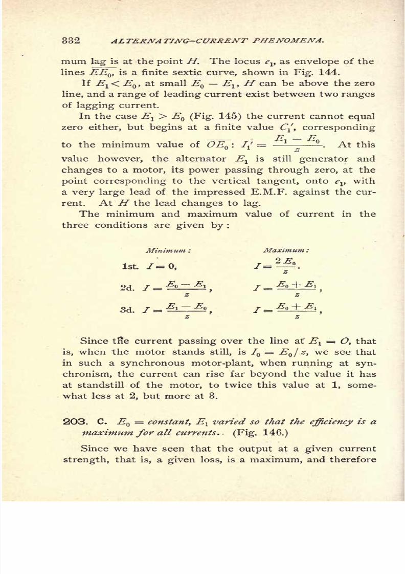
8/2/2019 Charles Steinmetz Theorycalculatio00steiiala
http://slidepdf.com/reader/full/charles-steinmetz-theorycalculatio00steiiala 358/557
332 ALTERNATING-CURRENT PHENOMENA.
mum lag is at the point H. The locus ev as envelope of the
lines EEty is a finite sextic curve, shown in Fig. 144.
If El< EQ ,
at small EQ
El ,H can be above the zero
line, and a range of leading current exist between two ranges
of lagging current.
In the case E1> E
Q (Fig. 145) the current cannot equal
zero either, but begins at a finite value C, corresponding
to the minimum value of OEQ :
// =*
-. At this
value however, the alternator E1
is still generator and
changes to a motor, its power passing through zero, at the
point corresponding to the vertical tangent, onto elf
with
a very large lead of the impressed E.M.F. against the cur-
rent. At H the lead changes to lag.
The minimum and maximum value of current in the
three conditions are given by :
Minimum: Maximum:
1st. 7=0, 7=^.
Since tfie current passing over the line at El= O, that
is, when the motor stands still, is 7 = EQ j z, we see that
in such a synchronous motor-plant, when running at syn-
chronism, the current can rise far beyond the value it has
at standstill of the motor, to twice this value at 1, some-
what less at 2, but more at 3.
203. C. EQ = constant, Elvaried so that the efficiency is a
maximum for all currents. (Fig. 146.)
Since we have seen that the output at a given current

8/2/2019 Charles Steinmetz Theorycalculatio00steiiala
http://slidepdf.com/reader/full/charles-steinmetz-theorycalculatio00steiiala 359/557
SYNCHRONOUS MOTOR. 333
the efficiency a maximum, when the current is in phase
with the induced E.M.F. EQof the generator, we have as
the locus of EQthe point EQ (Fig. 146), and when E with
increasing current varies on<?,E must vary on the straight
line ev parallel to c.
Hence, at no-load or zero current, El= E
,decreases
with increasing load, reaches a minimum at OE^ perpen-
dicular to clt
and then increasesagain,
reaches once more
Fig. 146.
El= E
Qat E?, and then increases beyond E . The cur-
rent is always ahead of the induced E.M.F. Elof the motor,
and by its lead compensates for the self-induction of the
system, making the total circuit non-inductive.
The power is a maximum at Ef, where OEf = EfEQ=
1/2 x ~OE^ and is then = / x "^7/2. Hence, since OEf =
EJ2,f=E()/2randP hence = the maxi-
mum power which, over a non-inductive line of resistance r
can be transmitted, at 50 per cent, efficiency, into a non-inductive circuit.

8/2/2019 Charles Steinmetz Theorycalculatio00steiiala
http://slidepdf.com/reader/full/charles-steinmetz-theorycalculatio00steiiala 360/557
-334 ALTERNATING-CURRENT PHENOMENA.
In this case,
In general, it is, taken from the diagram, at the condi-
tion of maximum efficiency :
Comparing these results with those in Chapter IX. on
Self-induction and Capacity, we see that the condition of
maximum efficiency of the synchronous motor system is
the same as in a system containing only inductance and
capacity, the lead of the current against the induced E.M.F.
Elhere acting in the same way as the condenser capacity
in Chapter IX.
204.
Fig. 147.
D. En= constant ; P = constant.
If the power of a synchronous motor remains constant,
we have (Fig. 147) / x OE^ = constant, or, since OE1
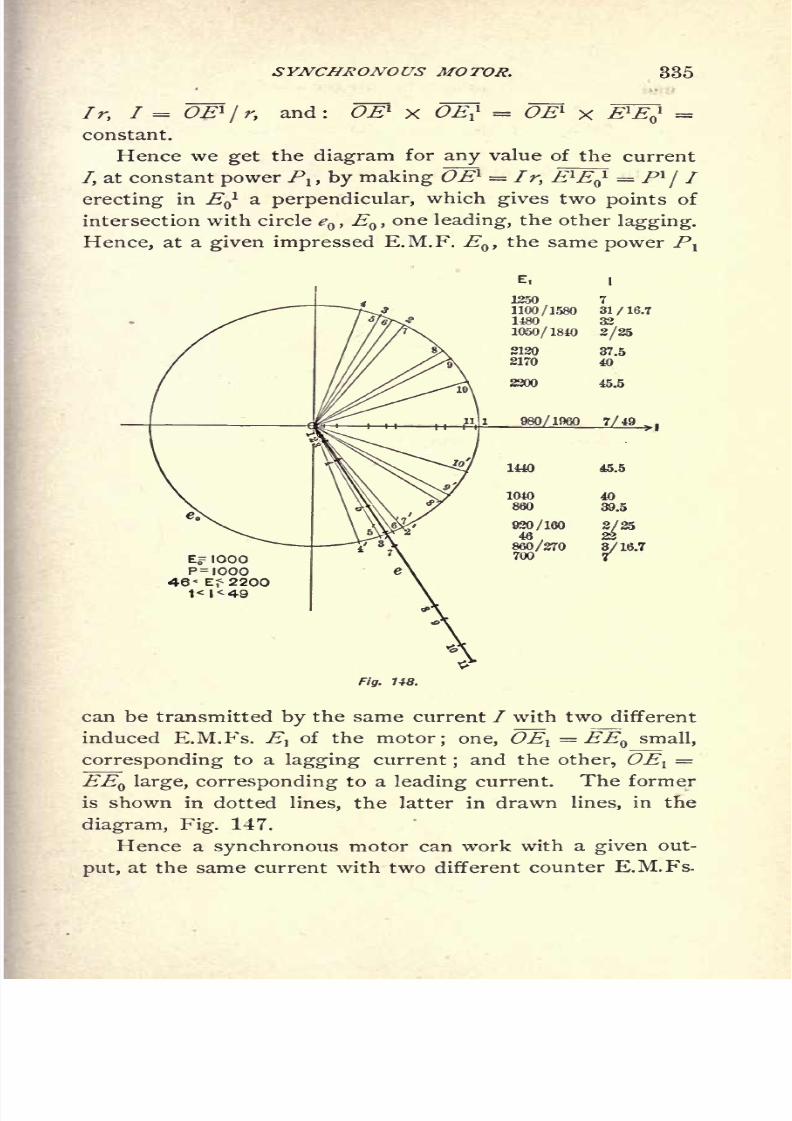
8/2/2019 Charles Steinmetz Theorycalculatio00steiiala
http://slidepdf.com/reader/full/charles-steinmetz-theorycalculatio00steiiala 361/557
SYNCHRONOUS MOTOR. 335
Ir, I = OE1
/ r, and: OE1 x OE? = O l
X E1
EJ =
constant.
Hence we get the diagram for any value of the current
/, at constant power Plt by making OE1 = I r, E1E 1 = Pl
jI
erecting in EQ
l a perpendicular, which gives two points of
intersection with circle eQ ,E
Q ,one leading, the other lagging.
Hence, at a given impressed E.M.F. EQ ,
the same power P
E,
1250 7
1100/1580 31/16.71480 32
1050/1840 2/25
2120
2170
37.5
40
45.5
16.7
Fig. U8.
can be transmitted by the same current I with two different
induced E.M.Fs. E}of the motor; one, OEl
= EEQ small,
corresponding to a lagging current;and the other, OEl
=
EEQ large, corresponding to a leading current. The former
is shown in dotted lines, the latter in drawn lines, in the
diagram, Fig. 147.
Hence a synchronous motor can work with a given out-
put, at the same current with two different counter E.M.Fs.
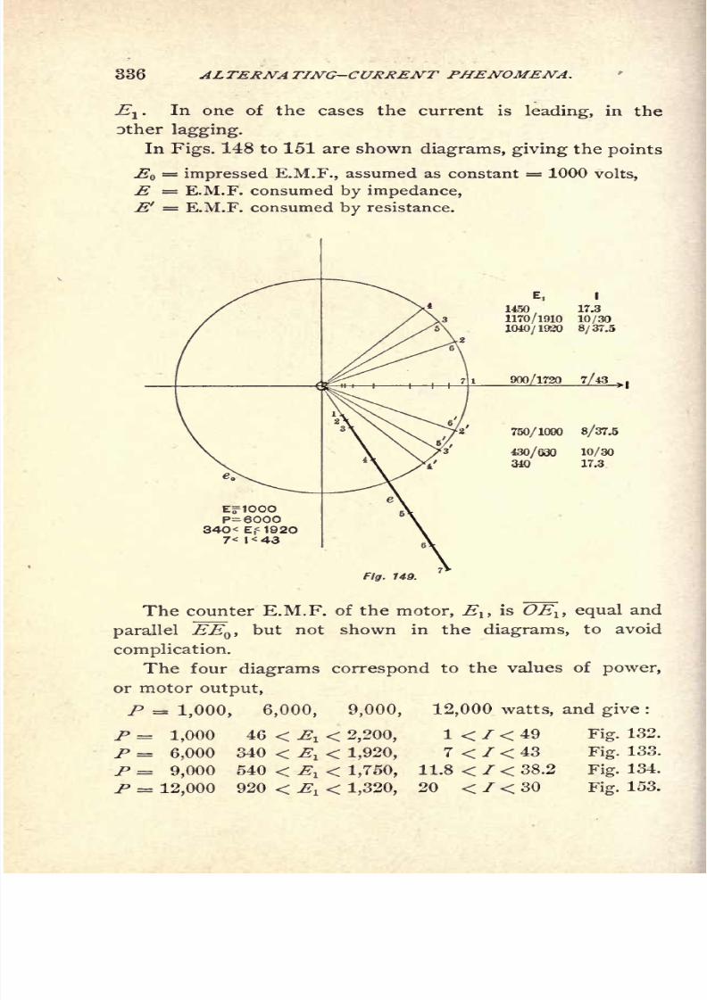
8/2/2019 Charles Steinmetz Theorycalculatio00steiiala
http://slidepdf.com/reader/full/charles-steinmetz-theorycalculatio00steiiala 362/557
336 ALTERNATING-CURRENT PHENOMENA.
E1
. In one of the cases the current is leading, in the
Dther lagging.
In Figs. 148 to 151 are shown diagrams, giving the points
E = impressed E.M.F., assumed as constant = 1000 volts,
E = E.M.F. consumed by impedance,
E' = E.M.F. consumed by resistance.
EflOOOP=600034O< E,<1920
7< I< 43
Fig. 149.
I
1450 17.3
1170/1910 10/30
1040/1930 8/37.5
10/30
17.3
of the motor, Eltis OElt equal and
shown in the diagrams, to avoid
The counter E.M.F.
parallel EEQ ,but not
complication.
The four diagrams correspond to the values of power,
or motor output,
P = 1,000, 6,000, 9,000, 12,000 watts, and give :
1 < I < 49 Fig. 132.P = 1,000 46 < El < 2,200,
P = 6,000 340 < , < 1,920, 7 < I < 43 Fig.133.
P = 9,000 540 < El < 1,750, 11.8 < / < 38.2 Fig. 134.
P = 920 < E < 20 < I < 30 153.
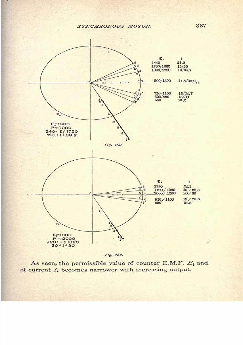
8/2/2019 Charles Steinmetz Theorycalculatio00steiiala
http://slidepdf.com/reader/full/charles-steinmetz-theorycalculatio00steiiala 363/557
SYNCHRONOUS MOTOR. 337
E, I
* 1440 21.2
31200/1660 15/30
1080/1750 13/34.7
900/1590 11.8/38.2.
720/1100 13/34.7
620/820 15/30
/
3540 21.2
3 1280 24.5
2 1120/1320 21/28.6
all l-QQO/1260 30/30
920/1100020
21/28.624.5
P=I200O920< E,< 1320
20<l<30
Fig. 151.
As seen, the permissible value of counter E.M.F. Evand
of current /, becomes narrower with increasing output.

8/2/2019 Charles Steinmetz Theorycalculatio00steiiala
http://slidepdf.com/reader/full/charles-steinmetz-theorycalculatio00steiiala 364/557
338 ALTERNATING-CURRENT PHENOMENA.
In the diagrams, different points of EQ are marked with
1, 2, 3 . . .,when corresponding to leading current, with
2 1,3 1
,. . . ,
when corresponding to lagging current.
The values of counter E.M.F. Evand of current 7 are
noted on the diagrams, opposite to the corresponding points
*o-
In this condition it is interesting to plot the current as
function of the induced E.M.F. El of the motor, for con-
stant power /V Such curves are given in Fig. 155 and
explained in the following on page 345.
205. While the graphic method is very convenient to
get a clear insight into the interdependence of the different
quantities, for numerical calculation it is preferable to ex-
press the diagrams analytically.
For this purpose,
Let z = Vr2
-j- x2 = impedance of the circuit of (equivalent)
resistance r and (equivalent) reactance x = 2 TT NL, containing
the impressed E.M.F. e * and the counter E.M.F. et of the syn-
chronous motor; that is, the E.M.F. induced in the motor arma-
ture by its rotation through the (resultant) magnetic field.
Let i = current in the circuit (effective values).
The mechanical power delivered by the synchronous
motor (including friction and core loss) is the electric
power consumed by the C.E.M.F. e1 ;
hence
p = *>! cos ft,^), (1)
thus,
*If f = E.M.F. at motor terminals, z = internal impedance of the
motor; if eo= terminal voltage of the generator, z = total impedance of line
and motor;if
t = E.M.F. of generator, that is, E.M.F. induced in generatorarmature by its rotation through the magnetic field, z includes the generator

8/2/2019 Charles Steinmetz Theorycalculatio00steiiala
http://slidepdf.com/reader/full/charles-steinmetz-theorycalculatio00steiiala 365/557
SYNCHRONOUS MOTOR. 339
The displacement of phase between current i and E.M.F.
= z i consumed by the impedance z is :
cos (ie)= -
sin(/<?)
x (3)
Since the three E.M.Fs. acting in the closed circuit :
e = E.M.F. of generator,
fi= C.E.M.F. of synchronous motor,
e = zi = E.M.F. consumed by impedance,
form a triangle, that is, c^and e are components of ^
,it is
(Fig. 152) :
e
1 2
e
Z .1 ?. ^2 ,'2
hence, cos (*,.#) = *- = - -. (5)
2 e^e '2,zie^
since, however, by diagram :
cos (el , e)= cos
(/,e
/', e^)
= cos(/, e)
cos(/, ^i) + sin
(t, e)sin
(/, ^) (6)
substitution of(2), (3)
and(5)
in(6) gives, after some trans-
position :
the Fundamental Equation of tJie Synchronous Motor, relat-
ing impressed E.M.F., <?;
C. E.M.F., ^ ;current z; power,
/, and resistance, r; reactance, x ; impedance s.
This equation shows that, at given impressed E.M.F. e$ f
and given impedance s = Vr2 + x*, three variables are left,
ev i,p, of which two are independent. Hence, at given ^and s, the current i is not determined by the load / only,
but also by the excitation, and thus the same current i can
represent widely different loads p, according to the excita-
tion;and with the same load, the current i can be varied
in a widerange, by varying
the field excitation e1
.
The meaning of equation (7)is made more perspicuous
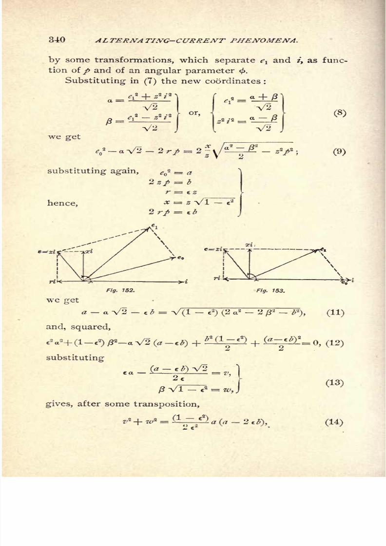
8/2/2019 Charles Steinmetz Theorycalculatio00steiiala
http://slidepdf.com/reader/full/charles-steinmetz-theorycalculatio00steiiala 366/557
340 ALTERNATING-CURRENT PHENOMENA.
by some transformations, which separate evand i, as func-
tion of/ and of an angular parameter <.
Substituting in(7) the new coordinates :
V2
V2
or,
_
V2
we get
substituting again, e<f = a
Izp = b
r = Z
hence,x = z Vl e
2
jr. 753.
we jret
a a V2 e b = V(l e2
) (2 a2 2 2 -
and, squared,
substituting
gives, after some transposition,
v* -f ze/
2
=(-
1 ~*") a (a 2 tb\
(9)
) (11)
0, (12)
(13)
(14)

8/2/2019 Charles Steinmetz Theorycalculatio00steiiala
http://slidepdf.com/reader/full/charles-steinmetz-theorycalculatio00steiiala 367/557
SYNCHRONOUS MOTOR. 341
hence'if
i* + w* = *
(16)
the equation of a circle with radius R.
Substituting now backwards, we get, with some trans-
positions :
{r* (ef + z*i2
) - z* (Vo2
- 2 r/)}2
+ {rx (e? - z*i2
)}2
=*2
.sV(^2
-4r/) (17)
the Fundamental Rquation of the Synchronous Motor in a
modified form.
The separation of e and i can be effected by the intro-
duction of a parameter < by the equations :
r3 (e? z2 / 2
) - z2 (ef 2rp)=xze()V<r a
rp cos <
rx (e?- z
2/
2
)=xze Vtf - 4 r/ sin
' l'
These equations (18), transposed, give
N
+ sin</>
The parameter <^> has no direct physical meaning, appar-
ently.
These equations (19) and(20), by giving the values ef
eland i as functions of / and the parameter < enable us
to construct the Power Characteristics of the Synchronous
Motor, as the curves relating evand i, for a given power /,
by attributing to < all different values.
8/2/2019 Charles Steinmetz Theorycalculatio00steiiala
http://slidepdf.com/reader/full/charles-steinmetz-theorycalculatio00steiiala 368/557
342 ALTERNATING-CURRENT PHENOMENA.
Since the variables v and w in the equation of the circle
(16) are quadratic functions of e1and
/',the Power Charac-
teristics of the Synchronous Motor are Quartic Curves.
They represent the action of the synchronous motor
under all conditions of load and excitation, as an element
of power transmission even including the line, etc.
Before discussing further these Power Characteristics,
some special conditions may be considered.
206. A. Maximum Output.
Since the expression of eland i [equations (19) and
(20)] contain the square root, W 2 4 rp, it is obvious
that the maximum value of / corresponds to the moment
where this
squareroot
disappears by passingfrom real to
imaginary ;that is,
tf_ 4 rp = 0,
r>
/ = .. (21)
This is the same value which represents the maximum
power transmissible by E.M.F., eQ ,
over a non-inductive line
of resistance, r\ or, more generally, the maximum power
which can be transmitted over a line of impedance,
into any circuit, shunted by a condenser of suitable capacity.
Substituting (21) in (19) and (20), we get,
and the displacement of phase in the synchronous motor.
cor(A,0-^--itc z
hence,
tan fa, /) = -?, (23)

8/2/2019 Charles Steinmetz Theorycalculatio00steiiala
http://slidepdf.com/reader/full/charles-steinmetz-theorycalculatio00steiiala 369/557
SYNCHRONOUS MOTOR. 343
thatis,
theangle
of internaldisplacement
in thesynchron-
ous motor i equal, but opposite to, the angle of displace-
ment of line impedance,
('i,= -
(', 0,= ~
<X '), (24)
and consequently,
(.-0,0=0; (25)
that is, the current, z, is in phase with the impressed
E.M.F., * .
If 2 < 2 r, el < <?
;that is, motor E.M.F. < generator E.M.F.
If z = 2r, e
l= e
;that is, motor E.M.F. = generator E.M.F.
If z > 2 r, <?! > r;that is, motor E.M.F. > generator E.M.F.
In either case, the current in the synchronous motor is
leading.
207. B. Running Light, p = 0.
When running light, or for / = 0, we get, by substitut-
ing in (19) and (20),
(26)
Obviously this condition cannot well be fulfilled, since p
must at least equal the power consumed by friction, etc.;
and thus the true no-load curve merely approaches the curve
/ = 0, being, however, rounded off, where curve (26) gives
sharp corners.
Substituting / = into equation (7) gives, after squar-
ing and transposing,
e* + e<
*
4- 3*,-- 2^V - 2 2
2rV + 2 ra
*'V - 2 *2*V = 0. (27)
This quartic equation can be resolved into the product
of two quadratic equations,
0.| (28)

8/2/2019 Charles Steinmetz Theorycalculatio00steiiala
http://slidepdf.com/reader/full/charles-steinmetz-theorycalculatio00steiiala 370/557
344 ALTERNATING-CURRENT PHENOMENA.
which are the equations of two ellipses, the one the image
of the other, both inclined with their axes.
The minimum value of C.E.M.F., eit is ^ = at / = ^2. (29)
The minimum value of current, z,is / = at et
= e . (30)
The maximum value of E.M.F., elt
is given by Equation (28)',
/= e* + 22z2 -e<?2 xie
l=
;
by the condition,
hence,
The maximum value of current, z, is given by equation
(28) by=
0, asde
l
(32)
If, as abscissas, elt and as ordinates, zi, are chosen, the
axis of these ellipses pass through the points of maximum
power given by equation (22).
It is obvious thus, that in the V-shaped curves of syn-
chronous motors running light, the two sides of the curves
are not straight lines, as usually assumed, but arcs of ellipses,
the one of concave, the other of convex, curvature.
These two ellipses are shown in Fig. 154, and divide the
whole space into six parts the two parts A and A', whose
areas contain the quartic curves (19) (20) of synchronous
motor, the two parts B and B', whose areas contain the
quartic curves of generator, and the interior space C and
exterior space D, whose points do not represent any actual
condition of the alternator circuit, but make el ,
i imaginary.
A and A' and the same B and B'',
are identical condi-
tions of the alternator circuit,differing merely by
a simul-
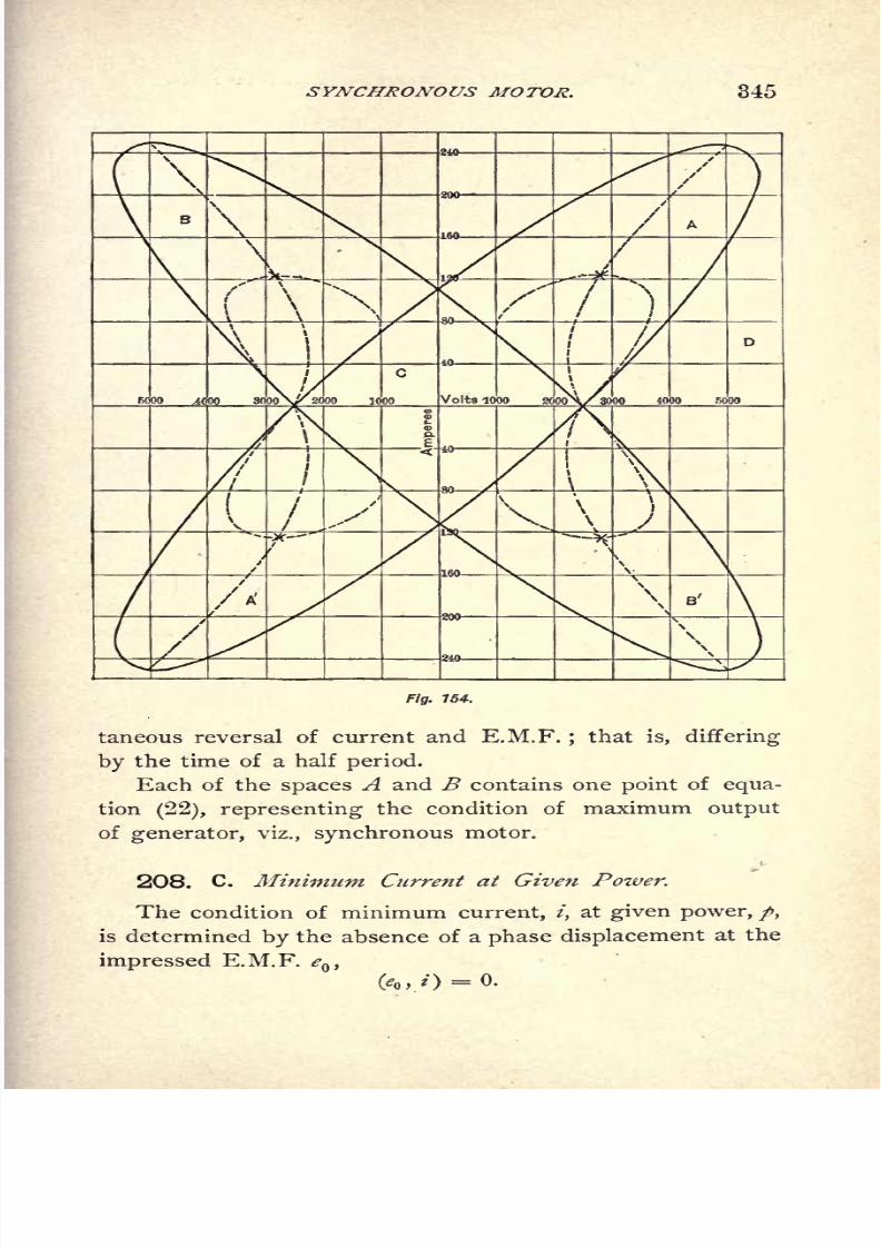
8/2/2019 Charles Steinmetz Theorycalculatio00steiiala
http://slidepdf.com/reader/full/charles-steinmetz-theorycalculatio00steiiala 371/557
SYNCHRONOUS MOTOR. 345
\
r
\ I
\4000 3000\^ 2000 1000 Volts 1000 2000\/3000 4000 5000
\
/A'\
\
Fig. 154.
taneous reversal of current and E.M.F.;that is, differing
by the time of a half period.
Each of the spaces A and B contains one point of equa-
tion(22), representing the condition of maximum output
of generator, viz., synchronous motor.
208. C. Minimum Current at Given Power.
The condition of minimum current, t, at given power, /,
is determined by the absence of a phase displacement at the
impressed E.M.F. eQ ,

8/2/2019 Charles Steinmetz Theorycalculatio00steiiala
http://slidepdf.com/reader/full/charles-steinmetz-theorycalculatio00steiiala 372/557
346 ALTERNATING-CURRENT PHENOMENA.
This gives from diagram Fig. 153,
e1
* = e(? + i*z*-2ie r, (33)
or, transposed,
This quadratic curve passes through the point of zero
current and zero power,
through the point of maximum power (22),
and through the point of maximum current and zero power,
en x
r(35)
and divides each of the quartic curves or power character-
istics into two sections, one with leading, the other with
lagging, current, which sections are separated by the two
pointsof
equation 34,the one
correspondingto
minimum,the other to maximum, current.
It is interesting to note that at the latter point the
current can be many times larger than the current which
would pass through the motor while at rest, which latter
current is,
/ ='J2, (36)
while at no-load, the current can reach the maximum value,
/=^, (35)
the same value as would exist in a non-inductive circuit of
the same resistance.
The minimum value at C.E.M.F. el}
at which coincidence
8/2/2019 Charles Steinmetz Theorycalculatio00steiiala
http://slidepdf.com/reader/full/charles-steinmetz-theorycalculatio00steiiala 373/557
SYNCHRONOUS MOTOR. 347
of phase (eQ , -i)= 0, can still be reached, is determined from
equation (34) by,
as
i e - - (37}
The curve of no-displacement, or of minimum current, is
shown in Figs. 138 and 139 in dotted lines.*
209. D. Maximum Displacement of Phase.
(e% , i}= maximum.
At a given power/ the input is,
A =P + i*r = e,i cos (* , *) ; (38)
hence,
cosfo, = /+/V.
(39)
At a given power /, this value, as function of the current
i, is a maximum when
d_(p +di\
this gives,(40)
or,
(41)
That is, the displacement of phase, lead or lag, is a
maximum, when the power of the motor equals the power
*It is interesting to note that the equation (34) is similar to the value,
<?!= \/(^ 2 r)
2z'
2jr2
, which represents the output transmitted over an
inductive line of impedance, z = vV 2 + jr2 into a non-inductive circuit.
Equation (34) is identical with the equation giving the maximum voltage,
e,at current, i, which can be produced by shunting the receiving circuit with a
condenser; that is, the condition of"complete resonance
"of the line, z =
xVr'2 + x'
2,with current, . Hence, referring to equation (35), e
l= t
~is
the maximum resonance
voltageof the line, reached when closed
by
a con-
denser of reactance, x.

8/2/2019 Charles Steinmetz Theorycalculatio00steiiala
http://slidepdf.com/reader/full/charles-steinmetz-theorycalculatio00steiiala 374/557
348 ALTERNATING-CURRENT PHENOMENA.
consumed by the resistance;that is, at the electrical effi-
ciency of 50 per cent.
Substituting (40) in equation (7) gives, after squaring
/ N
TSOO 8000^#WU 3000 3uOO
Fig. 155.
and transposing, the Ouartic Equation of Maximum Dis-
placement,
<>2 -
e*y + **z2
(s2 + 8 r2
) + 2 j*e* (5r2 - 2
2
)- 2 /V
(32 + 3^ = Oi (42)
The curve of maximumdisplacement
is shown in dash-
dotted lines in Figs. 154 and 155. It passes through the
8/2/2019 Charles Steinmetz Theorycalculatio00steiiala
http://slidepdf.com/reader/full/charles-steinmetz-theorycalculatio00steiiala 375/557
SYNCHRONOUS MOTOR. 349
point of zero current as singular or nodal point and
throughthe
pointof maximum
power,where the maximum
displacement is zero, and it intersects the curve of zero
displacement.
210. E. Constant Counter E.M.F.
At constant C.E.M.F., el= constant,
If
the current at no-load is not a minimum, and is lagging.
With increasing load, the lag decreases, reaches a mini-
mum, and then increases again, until the motor falls out of
step, without ever coming into coincidence of phase.
If
the current is lagging at no load;with increasing load the
lag decreases, the current comes into coincidence of phase
with eQ ,
then becomes leading, reaches a maximum lead;
then the lead decreases again, the current comes again into
coincidence of phase, and becomes lagging, until the motor
falls out of step.
If eQ< <?! ,
the current is leading at no load, and the
lead first increases, reaches a maximum, then decreases;
and whether the current ever comes into coincidence of
phase, and then becomes lagging, or whether the motor
falls out of step while the current is still leading, depends,
whether the C.E.M.F. at thepoint
of
maximum outputis
> <? or < * .
211. F. Numerical Instance.
Figs. 154 and 155 show the characteristics of a 100-
kilowatt motor, supplied from a 2500-volt generator over a
distance of 5 miles, the line consisting of two wires, No.
2 B. & S.G., 18 inches apart.
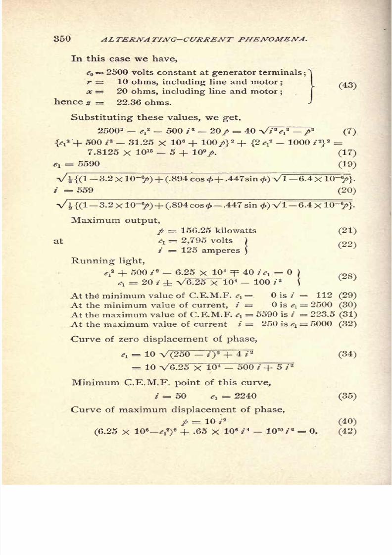
8/2/2019 Charles Steinmetz Theorycalculatio00steiiala
http://slidepdf.com/reader/full/charles-steinmetz-theorycalculatio00steiiala 376/557
350 ALTERNATING-CURRENT PHENOMENA.
In this case we have,
<? = 2500 volts constant at generator terminals;^|
r 10 ohms, including line and motor; /^gs
x = 20 ohms, including line and motor;
j
hence z = 22.36 ohms.
Substituting these values, we get,
25002 - e* - 500 i* - 20/ = 40 V*V -/ 2
(7)
{^2 + 500 ? 2
- 31.25 X 10 6
+ 100/} 2
+ (2 ^2
- 1000 / 2}
2
=7.8125 x 10¹⁵ - 5 + 109
/. (17)
el= 5590 (19)
V| {(1 3.2 x 10~6
/)+ (.894 cos<+ .447sin <) Vl-6.4xlO-6
/}.
* = 559 (20)
6.4xlO-6
/}.
Maximum output,
p = 156.25 kilowatts (21)
at *i= 2,795 volts
i = 125 amperes
Running light,
^ + 500 /a - 6.25 x 104
=p 40 /^ =
^ = 20/
V6.25 X10 4 100 i*
At the" minimum value of C.E.M.F. e1= is / = 112 (29)
At the minimum value of current, / = is el= 2500 (30)
At the maximum value of C.E.M.F. ev= 5590 is / = 223.5 (31)
At the maximum value of current i 250 is el= 5000 (32)
Curve of zero displacement of phase,
l
= 10 V(250-O
2
+ 4*a
(34)
= 10 V6.25 x 104 500 / + 5 /2
Minimum C.E.M.F. point of this curve,
/ = 50 ^ = 2240 (35)
Curve of maximum displacement of phase,
/ = 10 *'
2
(40)
(6.25 X 10⁶
-^2
)
2
+ .65 X 106/ - 10 10
/2
= 0. (42)

8/2/2019 Charles Steinmetz Theorycalculatio00steiiala
http://slidepdf.com/reader/full/charles-steinmetz-theorycalculatio00steiiala 377/557
SYNCHRONOUS MOTOR. 351
Fig. 154 gives the two ellipses of zero power, in drawn
lines, with the curves of zero displacement in dotted, the
curves of maximum displacement in dash-dotted lines, and
the points of maximum power as crosses.
Fig. 155 gives the motor-power characteristics, for,
/ = 10 kilowatts.
p = 50 kilowatts.
/= 100 kilowatts.
p = 150 kilowatts.
p = 156.25 kilowatts.
together with the curves of zero displacement, and of maxi-
mum displacement.
212. G. Discussion of Results.
The characteristic curves of the synchronous motor, as
shown in Fig. 155, have been observed frequently, with
their essential features, the V-shaped curve of no load, with
the point rounded off and the two legs slightly curved, the
one concave, the other convex;the increased rounding off
and contraction of the curves with increasing load ;
andthe gradual shifting of the point of minimum current with
increasing load, first towards lower, then towards higher,
values of C.E.M.F. el
.
The upper parts of the curves, however, I have never
been able to observe experimentally, and consider it as
probable that they correspond to a condition of synchro-
nous motor-running, which is unstable. The experimental
observations usually extend about over that part of the
curves of Fig. 155 which is reproduced in Fig. 156, and in
trying to extend the curves further to either side, the motor
is thrown out of synchronism.
It must be understood, however, that these power char-
acteristics of the synchronous motor in Fig. 155 can be con-
sidered as approximations only, since a number of assump-
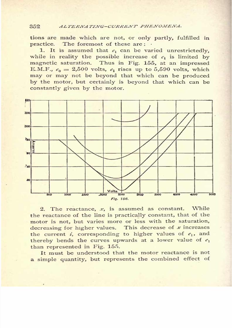
8/2/2019 Charles Steinmetz Theorycalculatio00steiiala
http://slidepdf.com/reader/full/charles-steinmetz-theorycalculatio00steiiala 378/557
352 ALTERNA TING-CURRENT PHENOMENA.
tions are made which are not, or only partly, fulfilled in
practice. The foremost of these are :
1. It is assumed that elcan be varied unrestrictedly,
while in reality the possible increase of el
is limited by
magnetic saturation. Thus in Fig. 155, at an impressed
E.M.F., eQ= 2,500 volts, e
lrises up to 5,590 volts, which
may or may not be beyond that which can be produced
bythe
motor,but
certainlyis
beyond that which can beconstantly given by the motor.
Fig. 156.
2.
The reactance, x,is assumed as constant. While
the reactance of the line is practically constant, that of the
motor is not, but varies more or less with the saturation,
decreasing for higher values. This decrease of x increases
the current /, corresponding to higher values of elt and
thereby bends the curves upwards at a lower value of ^
than represented in Fig. 155.
It must be understood that the motor reactance is not
the combined effect of
8/2/2019 Charles Steinmetz Theorycalculatio00steiiala
http://slidepdf.com/reader/full/charles-steinmetz-theorycalculatio00steiiala 379/557
SYNCHRONOUS MOTOR. 353
self-induction, that is, the E.M.F. induced in the armature
conductor by the current flowing therein and armature
reaction, or the variation of the C.E.M.F. of the motor
by the change of the resultant field, due to the superposi-
tion of the M.M.F. of the armature current upon the field
excitation;that is, it is the "
synchronous reactance."
3. These curves in Fig. 155 represent the conditions
of constant electric power of the motor, thus including the
mechanical andthe
magneticfriction
(core loss). Whilethe mechanical friction can be considered as approximately
constant, the magnetic friction is not, but increases with
the magnetic induction;that is, with elf and the same holds
for the power consumed for field excitation.
Hence the useful mechanical output of the motor will
on the same curve, / = const., be larger at points of lower
C.E.M.F., elt than at points of higher e^\ and if the curves
are plotted for constant useful mechanical output, the whole
system of curves will be shifted somewhat towards lower
values of ^ ;hence the points of maximum output of the
motor correspond to a lower E.M.F. also.
It is obvious that the -true mechanical power-character-
istics of the synchronous motor can be determined only
in the case of the particular conditions of the installation
under consideration.
8/2/2019 Charles Steinmetz Theorycalculatio00steiiala
http://slidepdf.com/reader/full/charles-steinmetz-theorycalculatio00steiiala 380/557
354 ALTERNA TING-CURRENT PHENOMENA,
CHAPTER XX.
COMMUTATOR MOTORS.
213. Commutator motors that is, motors in which
the current enters or leaves the armature over brushes
through a segmental commutator have been built of
various types, but have not found any extensive appli-
cation, in consequence of the superiority of the induction
and synchronous motors, due to the absence of commu-
tators.
The main subdivisions of commutator motcrs are the
repulsion motor, the series motor, and the shunt motor.
REPULSION MOTOR.
214. The repulsion motor -is an induction motor or
transformer motor ; that is, a motor in which the main
current enters the primary member or field only, while
in the secondary member, or armature, a current is in-
duced, arid thus the action is due to the repulsive thrust
between induced current and inducing magnetism.
As stated under the heading of induction motors, a
multiple circuit armature is required for the purpose of
having always secondary circuits in inductive relation to
the primary circuit during the rotation. If with a single-
coil field, these secondary circuits are constantly closed
upon themselves as in the induction motor, the primary
circuit will not exert a rotary effect upon the armature
while at rest, since in half of the armature coils the cur-
rent is induced so as to give a rotary effort in the onedirection, and in the other half the current is induced to
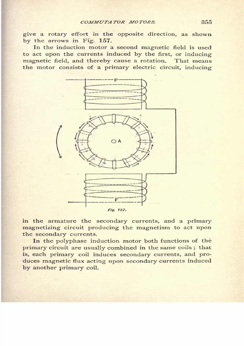
8/2/2019 Charles Steinmetz Theorycalculatio00steiiala
http://slidepdf.com/reader/full/charles-steinmetz-theorycalculatio00steiiala 381/557
COMMUTATOR MOTORS. 355
give a rotary effort in the opposite direction, as shown
bythe arrows in
Fig.
157.
In the induction motor a second magnetic field is used
to act upon the currents induced by the first, or inducing
magnetic field, and thereby cause a rotation. That means
the motor consists of a primary electric circuit, inducing
Fig. 157.
in the armature the secondary currents, and a primary
magnetizing circuit producing the magnetism to act upon
the secondary currents.
In the polyphase induction motor both functions of the
primary circuit are usually combined in the same coils;that
is, each primary coil induces secondary currents, and pro-
duces magnetic flux acting upon secondary currents induced
by another primary coil.
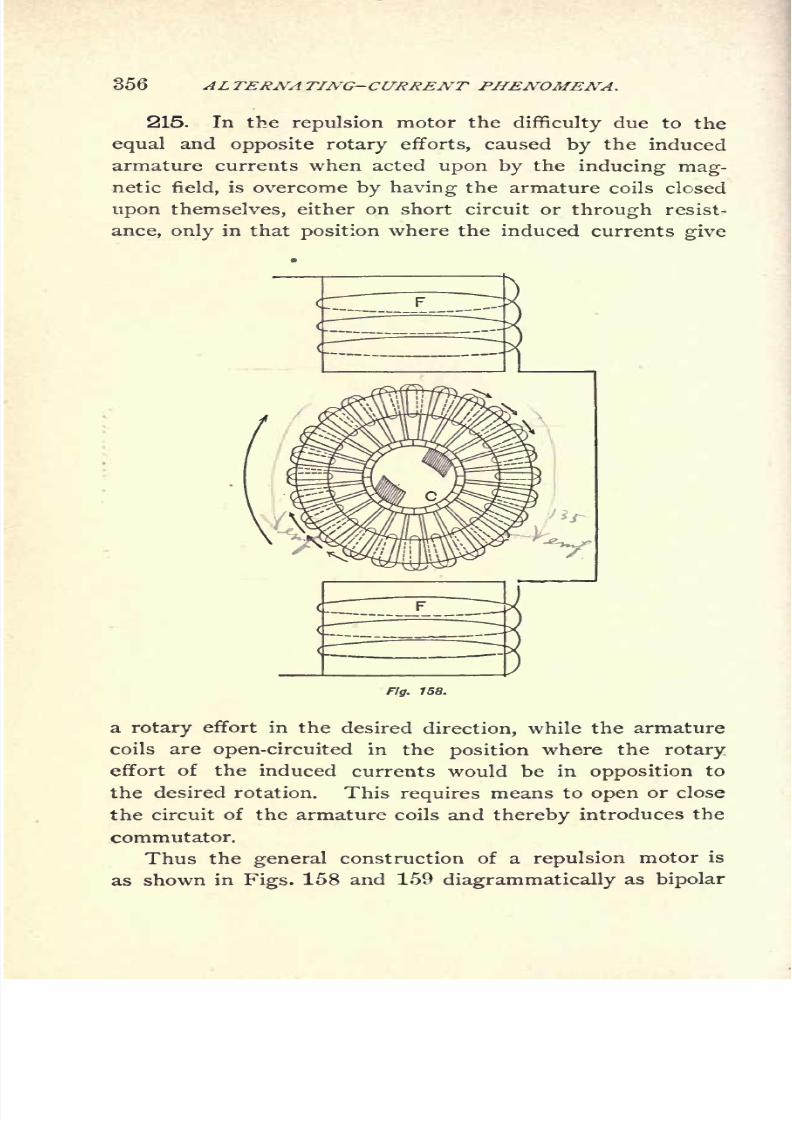
8/2/2019 Charles Steinmetz Theorycalculatio00steiiala
http://slidepdf.com/reader/full/charles-steinmetz-theorycalculatio00steiiala 382/557
356 ALTERNA TING-CURRENT PHENOMENA.
215. In the repulsion motor thedifficulty due to the
equal and opposite rotary efforts, caused by the induced
armature currents when acted upon by the inducing mag-
netic field, is overcome by having the armature coils closed
upon themselves, either on short circuit or through resist-
ance, only in that position where the induced currents give
Fig. 158.
a rotary effort in the desired direction, while the armature
coils are open-circuited in the position where the rotary
effort of the induced currents would be in opposition to
the desired rotation. This requires means to open or close
the circuit of the armature coils and thereby introduces the
commutator.
Thus thegeneral
construction of arepulsion
motor is
as shown in Figs. 158 and 159 diagrammatically as bipolar

8/2/2019 Charles Steinmetz Theorycalculatio00steiiala
http://slidepdf.com/reader/full/charles-steinmetz-theorycalculatio00steiiala 383/557
COMMUTATOR MOTORS. 357
motor. The field is a single-phase alternating field F, the
armature showndiagrammatically
as
ringwound A consists
of a number of coils connected to a segmental commutator
C, in general in the same way as in continuous-current ma-
chines. Brushes standing under an angle of about 45 with
the direction of the magnetic field, short-circuit either a
Fig. 159.
part of the armature coils as shown in Fig. 158, or the
whole armature by a connection from brush to brush as
shown in Fig. 159.
The former arrangement has the disadvantage of using a
part of the armature coils only. The second arrangementhas the disadvantage that, in the passage of the brush from
segment to segment, individual armature coils are short-

8/2/2019 Charles Steinmetz Theorycalculatio00steiiala
http://slidepdf.com/reader/full/charles-steinmetz-theorycalculatio00steiiala 384/557
358 ALTERNA TING-CURRENT PHENOMENA.
circuited, and thereby give a torque in opposite direction to
the torque developed by the main induced current flowing
through the whole armature from brush to brush.
216. Thus the repulsion motor consists of a primary
electric circuit, a magnetic circuit interlinked therewith,
and a secondary circuit closed upon itself and displaced in
Fig. 160.
space by 45 in a bipolar motor from the direction of
the magnetic flux, as shown diagrammatically in Fig. 160.*
This secondary circuit, while set in motion, still remains
in the same position of 45 displacement, with the magnetic
flux, or rather, what is theoretically the same, when moving
out of this position, is replaced by other secondary circuits
entering this position of 45 displacement.

8/2/2019 Charles Steinmetz Theorycalculatio00steiiala
http://slidepdf.com/reader/full/charles-steinmetz-theorycalculatio00steiiala 385/557
COMMUTATOR MOTORS. 359
titles, as E.M.F., current, resistance, reactance, etc., are
assumed as reduced to the
primarycircuit
bythe ratio of
turns, in the same way as done in the chapter on Induction
Motors.
217. Let
$ = maximum magnetic flux per field pole ;
e = effective E.M.F. induced thereby in the field turns; thus,
where ;/ = number of turns, N= frequency.
<?108
thus, 4> = --\&-anN
The instantaneous value of magnetism is
<f>= <& sin
(3 ;
and the flux interlinked with the armature circuit
<x= <I> sin
/3sin X
;
when X is the angle between the plane of the armature coil
and the direction of the magnetic flux. (Usually about 45.)
The E.M.F. induced in the armature circuit, of n turns,
(as reduced to primary circuit),is thus,
e = _ n ^1 10- 8
,= - n 4- sin B sin X lO" 8
,
at at
= - n$> sin X cos(3 + sin
(3cos X 10~ 8
.
If N= frequency in cycles per second, N:=
frequency
of rotation or speed in cycles per second, and k = N^/N
speed we havefrequency
thus, gl= 2-TrnJV {sin X cos
/? + k cos X sin B\ 10~ 8,
or, since $ = ,
et = e V2 {sin X cos /3 + k cos X sin fi\.

8/2/2019 Charles Steinmetz Theorycalculatio00steiiala
http://slidepdf.com/reader/full/charles-steinmetz-theorycalculatio00steiiala 386/557
360 ALTERNATING-CURRENT PHENOMENA.
218. Introducing now complex quantities, and counting
the time from the zero value of rising magnetism, the mag-
netism is represented by /4>,
the primary induced E.M.F., E =e,
the secondary induced E.M.F., 1
= e {sin X +j"k cos X|;
hence, if
Zl= r
1 jx1=
secondary impedance reduced to primary circuit,
Z = r jx = primary impedance,
Y = g jb =exciting admittance,
we have,
& sin X -f- jk cos Asecondary current, 7
X= L = - e- _
-,
primary exciting current, I = eY= e (g +jb},
hence, total primary current,
Primary impressed E.M.F., E = E + IZ\
= e 1 + (sinX
Neglecting in E the last term, as of higher order,
= ej1 + sin X +jk cos X ^ ^4^ j
;
or, eliminating imaginary quantities,
e V(?i + r sin X -f- kx cos X)2 + (x^ + x sin X kr cos X)
2
The power consumed by the component of primary
counter E.M.F., whose flux is interlinked with the secondary
e sin X, is,
f =[e
sin X /]'= ^inXfosuiX-^cosX)
,
r\ + x
\
the power consumed by the secondary resistance is,
_ 2 _ **ri (
sin2 x + ^ cos2 x)
hencethe
difference,or the mechanical
power developed bythe motor armature,

8/2/2019 Charles Steinmetz Theorycalculatio00steiiala
http://slidepdf.com/reader/full/charles-steinmetz-theorycalculatio00steiiala 387/557
COMMUTATOR MOTORS. 361
and substituting for e,
egk cos X (x^ sin X + r^k cos X)~fa + r sin X + kx cos X)
2 + (xl + x sin \ kr cosX)
2'
and the torque in synchronous watts,
P <?2cos X (x1
sin X + r^k cos X)~~
/
~~
(/i + ?" sin A + # cos X)2 + (xt + x sin X kr cos X)
2
or T= V27r^lO-8
[/!<!> sin X 7X cos A]' = [^/! cos X}>
_ ^ cos X (xlsin X + r^k cos X)
r 2 + x 2
The stationary torque is, k = 0,
_ ifo
2^ sin X cos X=(rx + r sin X)
2 + (^ + * sin X)2
'
and neglecting the primary impedance, r=
= x,
_ e^x^ sin X cos X _ (fo
2^ sin2 X
which is a maximum at X = 45.
At speed k, neglecting r = =x,
<?
2cos X (X sin X + r^k cos X)
r 2 j-^2~'
which is a maximum for - =0, which gives,
cot 2 X = . For k = 0, X = 45;for k = oo
,X = 0.
that is, in the repulsion motor, with increasing speed, the
angle of secondary closed circuit, X, has to be reduced to
get maximum torque.
219. At A = 45 we have,
(rx V2 + r + *)2 + (^ V2 + x - krf
and the power,
p= ^k (x, +r,K)_
(r, V2 + r + kx)*+(xi ^2 + x - krf'
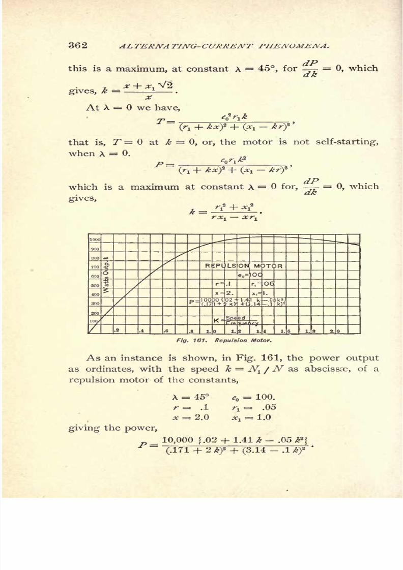
8/2/2019 Charles Steinmetz Theorycalculatio00steiiala
http://slidepdf.com/reader/full/charles-steinmetz-theorycalculatio00steiiala 388/557
362 ALTERNATING-CURRENT PHENOMENA.
this is amaximum,
atconstant X
=45,
for =0,
whichdk
gives, k = 1
At X = we have,
T--
fa + kxf + (*t-
krf
that is, T= at k =
0, or,the motor is not
self-starting,
when X = 0.
P =
dPwhich is a maximum at constant X = for,
- =0, which
dkgives,
rx-,xr-.
F/fir.161. Repulsion Motor.
As an instance is shown, in Fig. 161, the power output
as ordinates, with the speed k = N^_ /N as abscissae, of a
repulsion motor of the constants,
X = 45 e = 100.
r= .1 r1= .05
* = 2.0 *x= 1.0
giving the power,
10,000 f .02 + 1.41 k .05 ffj~~
.171 2 2 - .1
'

8/2/2019 Charles Steinmetz Theorycalculatio00steiiala
http://slidepdf.com/reader/full/charles-steinmetz-theorycalculatio00steiiala 389/557
COMMUTATOR MOTORS.
SERIES MOTOR. SHUNT MOTOR.
220. If, in a continuous-current motor, series motor as
well as shunt motor, the current is reversed, the direction
of rotation remains the same, since field magnetism and
armature current have reversed their sign, and their prod-
Fig. 162. Series Motor.
net, the torque, thus maintained the same sign. There-
fore such a motor, when supplied by an alternating current,
will operate also, provided that the reversals in field and
in armature take place simultaneously. In the series motor
this is necessarily the case, the same current passing through
field and through armature.
With an alternating current in the field, obviously the
8/2/2019 Charles Steinmetz Theorycalculatio00steiiala
http://slidepdf.com/reader/full/charles-steinmetz-theorycalculatio00steiiala 390/557
364 ALTERNATING-CURRENT PHENOMENA.
magnetic circuit has to be laminated to exclude eddy cur-
rents.
Let, in a series 'motor, Fig. 146,
<l> = effective magnetism per pole,
n = number of field turns per pole in series,
i= number of armature turns in series between brushes,
/ = number of poles,
(R. = magnetic reluctance of field circuit,*
(R!=
magnetic reluctance of armature circuit,!
4>i= effective magnetic flux produced by armature current
(cross magnetization) per pole,
r = resistance of field (effective resistance, including hys-
teresis),
rj= resistance of armature (effective resistance, including hys-
teresis),
N =frequency of alternations,
N = speed in cycles per second.
It is then,
E.M.F. induced in armature conductors by their rotation
through the magnetic field (counter E.M.F. of motor).
E =4E.M.F. of self-induction of field,
E' =
E.M.F. of self-induction of armature,
^/ = 2 7r1^V<I>
110- 8
,
E.M.F. consumed by resistance,
Er=
(r + *i) I,
where
/ = current passing through motor, in amperes effective.
Further, it is :
Field magnetism : $ = n 7108
/ (R
* That is, the main magnetic circuit of the motor.
t That is, the magnetic circuit of the cross magnetization, produced by the armature

8/2/2019 Charles Steinmetz Theorycalculatio00steiiala
http://slidepdf.com/reader/full/charles-steinmetz-theorycalculatio00steiiala 391/557
COMMUTATOR MOTORS. 365
Armature magnetism :
Wj/10
8
1 =
"V";
Substituting these values,
(R
ptfNIE' =
(R
E 1 = ^^ ni NI .
Er= (r + rj)
/
Thus the impressed E.M.F.,
or, since
i,2
x = 2 TTN^- = reactance of field;
(R
2-n-jV = reactance of armature
fti
and
/
,
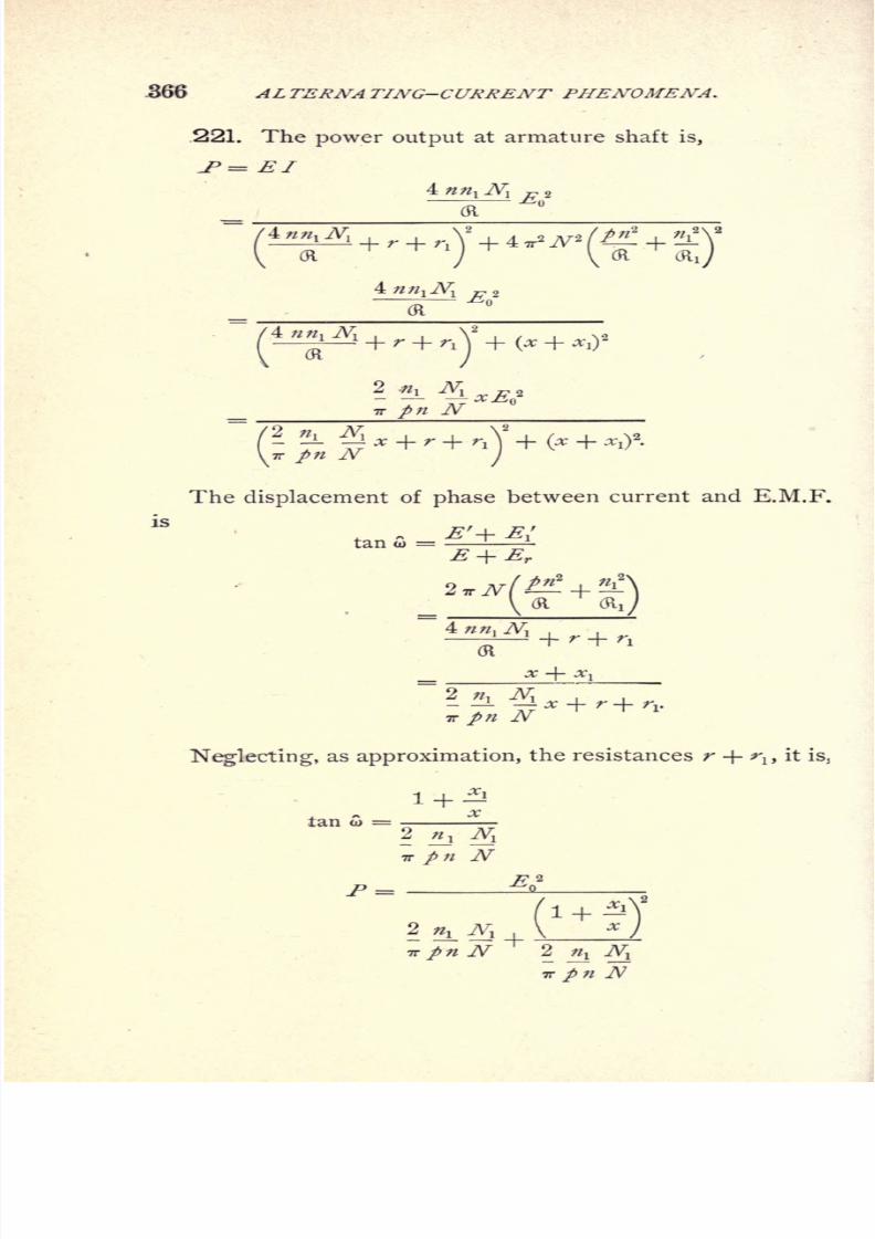
8/2/2019 Charles Steinmetz Theorycalculatio00steiiala
http://slidepdf.com/reader/full/charles-steinmetz-theorycalculatio00steiiala 392/557
366 AL TERNA TING-CURRENT PHENOMENA.
221. The power output at armature shaft is,
J>= El
\(R (R
fi- *Ef7T 7V^
/2 n Nx _j_
r _^_
The displacement of phase between current and E.M.F.
tan CD =
Neglecting, as approximation, the resistances r + rlf
it
1 + |!lan W =
? j ^7T / 7V
^n2
1+^'^
/ TV
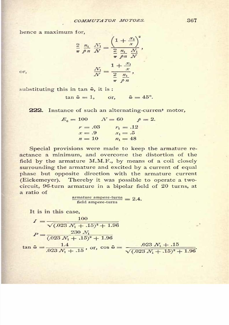
8/2/2019 Charles Steinmetz Theorycalculatio00steiiala
http://slidepdf.com/reader/full/charles-steinmetz-theorycalculatio00steiiala 393/557
COMMUTATOR MOTORS. 367
hence a maximum for,
3r
7T
substituting this in tan w, it is :
tan o> = 1, or, w = 45.
222. Instance of such an alternating-current motor,
^ = 100 AT =60 p = 2.
r = .03 ri = .12
x = .9 *! = .5
n = 10j= 48
Special provisions were made to keep the armature re-
actance a minimum, and overcome the distortion of the
field by the armature M.M.F., by means of a coil closely
surrounding the armature and excited by a current of equal
phase but opposite direction with the armature current
(Eickemeyer). Thereby it was possible to operate a two-
circuit, 96-turn armature in a bipolar field of 20 turns, at
a ratio of
armature ampere-turns r> A
field ampere-turns
It is in this case,
100
V(.023 vVi + ,15)2 + 1.96
230 ./v;
(.023 A! + .15)2 + 1.96
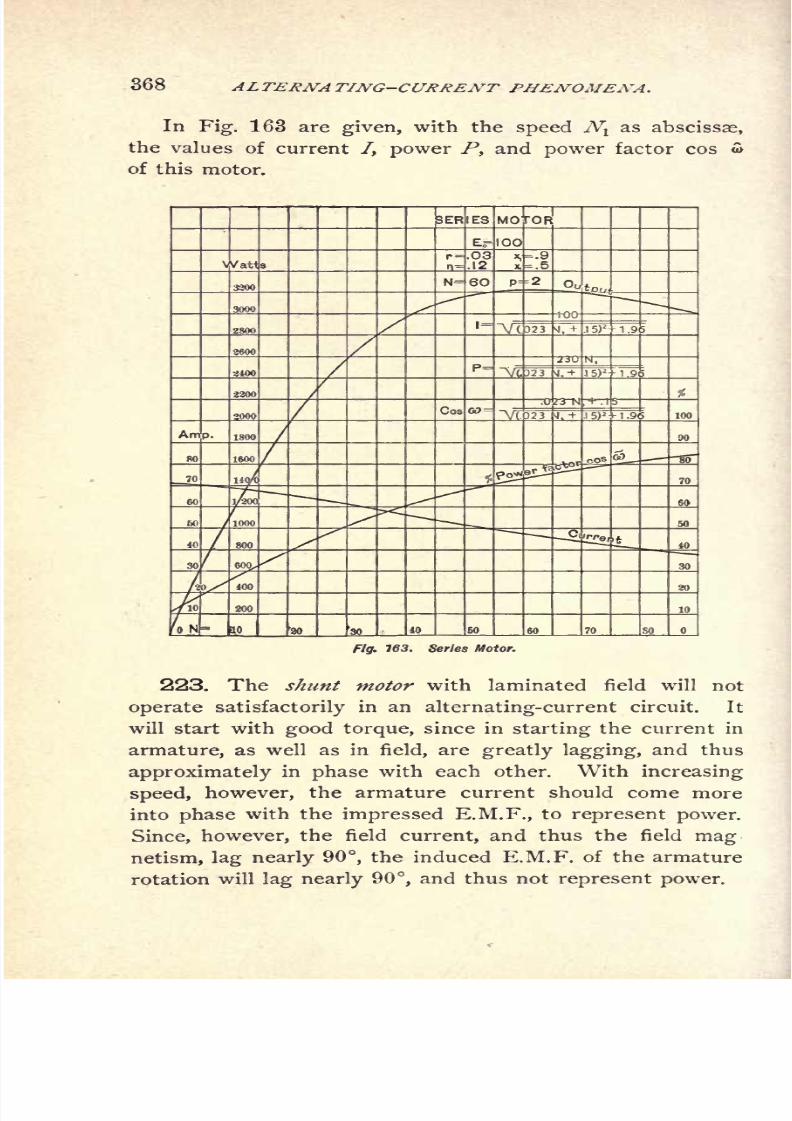
8/2/2019 Charles Steinmetz Theorycalculatio00steiiala
http://slidepdf.com/reader/full/charles-steinmetz-theorycalculatio00steiiala 394/557
368 ALTERNATING-CURRENT PHENOMENA.
In Fig. 163 are given, with the speed Nvas abscissae,
the values of current /, power P, and power factor cos o>
of this motor.
Fig. 163. Series Motor.
223. The shunt motor with laminated field will not
operate satisfactorily in an alternating-current circuit. It
will start with good torque, since in starting the current in
armature, as well as in field, are greatly lagging, and thus
approximately in phase with each other. With increasing
speed, however, the armature current should come more
into phase with the impressed E.M.F., to represent power.
Since, however, the field current, and thus the field mag
netism, lag nearly 90,the induced E.M.F. of the armature
rotation will lag nearly 90, and thus not represent power.

8/2/2019 Charles Steinmetz Theorycalculatio00steiiala
http://slidepdf.com/reader/full/charles-steinmetz-theorycalculatio00steiiala 395/557
COMMUTATOR MOTORS. 369
Hence, to make a shunt motor work on alternating-cur-
rent circuits, the magnetism of the field should be approxi-
mately in phase with the impressed E.M.F., that is, the field
reactance negligible. Since the self-induction of the field is
far in excess to its resistance, this requires the insertion of
negative reactance, or capacity, in the field.
If the self-induction of the field circuit is balanced by
capacity, the motor will operate, provided that the armature
reactance is low, and that in starting sufficient resistance
is inserted in the armature circuit to keep the armature
current approximately in phase with the E.M.F. Under
these conditions the equations of the motor will be similar
to those of the series motor.
However, such motors have not been introduced, due to
the difficulty of maintaining the balance between capacity
and self-induction in the field circuit, which depends upon
the square of the frequency, and thus is disturbed by the
least change of frequency.
The main objection to both series and shunt motors is
the destructive sparking at the commutator due to the in-
duction of secondary currents in those armature coils which
passunder the
brushes. Asseen in
Fig. 162, with thenormal position of brushes midway between the field poles,
the armature coil which passes under the brush incloses the
total magnetic flux. Thus, in this moment no E.M.F. is
induced in the armature coil due to its rotation, but the
E.M.F. induced by the alternation of the magnetic flux
has a maximum at this moment, and the coil, when short-
circuited by the brush, acts as a short-circuited secondary
to the field coils as primary ;that is, an excessive current
flows through this armature coil, which either destroys it,
or at least causes vicious sparking when interrupted by the
motion of the arm'ature.
To overcome this difficulty various arrangements have
been proposed, but have not found an application.
8/2/2019 Charles Steinmetz Theorycalculatio00steiiala
http://slidepdf.com/reader/full/charles-steinmetz-theorycalculatio00steiiala 396/557
370 ALTERNATING-CURRENT PHENOMENA.
224.Compared
with thesynchronous
motor which has
practically no lagging currents, and the induction motor
which reaches very high power factors, the power factor of
the series motor is low, as seen from Fig. 163, which repre-
sents about the best possible design of such motors.
In the alternating-series motor, as well as in the shunt
motor, no position of an armature coil exists wherein the
coil is dead; but in every position E.M.F. is induced in the
armature coil : in the position parallel with the field flux an
E.M.F. in phase with the current, in the position at right
angles with the field flux an E.M.F. in quadrature with the
current, intermediate E.M.Fs. in intermediate positions.
At the speed irJV/2 the two induced E.M.Fs. in phase and
in quadrature with the current are equal, and the armature
coils are the seat of a complete system of symmetrical and
balanced polyphase E.M.Fs. Thus, by means of stationary
brushes, from such a commutator polyphase currents could
be derived.

8/2/2019 Charles Steinmetz Theorycalculatio00steiiala
http://slidepdf.com/reader/full/charles-steinmetz-theorycalculatio00steiiala 397/557
REACTION MACHINES. 371
CHAPTER XXI.
REACTION MACHINES.
225. In the chapters on Alternating-Current Genera-
tors and on Induction Motors, the assumption has been
made that the reactance x of the machine is a constant.
While this is more or less approximately the case in many
alternators, in others, especially in machines of large arma-
ture reaction, the reactance x is variable, and is different in
the different positions of the armature coils in the magnetic
circuit. This variation of the reactance causes phenomena
which do not find their explanation by the theoretical cal-
culations made under the assumption of constant reactance.
It is known that synchronous motors of large and
variable reactance keep in synchronism, and are able to
do a considerable amount of work, and even carry under
circumstances full load,if
the field-exciting circuit is
broken, and thereby the counter E.M.F. E reduced to
zero, and sometimes even if the field circuit is reversed
and the counter E.M.F. E made negative.
Inversely, under certain conditions of load, the current
and the E.M.F. of a generator do not disappear if the gene-
rator field is broken, or even reversed to a small negative
value, in which latter case the current flows against the
E.M.F. EQ
of the generator.
Furthermore, a shuttle armature without any winding
will in an alternating magnetic field revolve when once
brought up to synchronism, and do considerable work as
a motor.
These phenomena are not due to remanent magnetism
nor to the magnetizing effect of Foucault currents, because

8/2/2019 Charles Steinmetz Theorycalculatio00steiiala
http://slidepdf.com/reader/full/charles-steinmetz-theorycalculatio00steiiala 398/557
372 ALTERNA TING-CURRENT PHENOMENA.
they exist also in machines with laminated fields, and exist
if the alternator is brought up to synchronism by external
means and the remanent magnetism of the field poles de-
stroyed beforehand by application of an alternating current.
226. These phenomena cannot be explained under the
assumption of a constant synchronous reactance; because
in this case, at no-field excitation, the E.M.F. or counter
E.M.F. of the machine is zero, and the only E.M.F. exist-
ing in the alternator is the E.M.F. of self-induction; that
is, the E.M.F. induced by the alternating current upon
itself. If, however, the synchronous reactance is constant,
the counter E.M.F. of self-induction is in quadrature with
the current and wattless; that is, can neither produce nor
consume energy.'
In the synchronous motor running without field excita-
tion, always a large lag of the current behind the impressed
E.M.F. exists; and an alternating generator will yield an
E.M.F. without field excitation, only when closed by an
external circuit of large negative reactance;that is, a circuit
in which the current leads the E.M.F., as a condenser, or
an over-excited synchronous motor, etc.
Self-excitation of the alternator by armature reaction
can be explained by the fact that the counter E.M.F. of
self-induction is not wattless or in quadrature with the cur-
rent, but contains an energy component ;that is, that the
reactance is of the form X = h jx, where x is the wattless
component of reactance and h the energy component of
reactance, and h is positive if the reactance consumes
power, in which case the counter E.M.F. of self-induc-
tion lags more than 90 behind the current, while h is
negative if the reactance produces power, in which case
the counter E.M.F. of self-induction lags less than 90
behind the current.
227. A case of this nature has been discussed already

8/2/2019 Charles Steinmetz Theorycalculatio00steiiala
http://slidepdf.com/reader/full/charles-steinmetz-theorycalculatio00steiiala 399/557
REACTION MACHINES. 373
There the effect of magnetic hysteresis was found to distort
the current wave in such a way that the equivalent sine
wave, that is, the sine wave of equal effective strength and
equal power with the distorted wave, is in advance of the
wave of magnetism by what is called the angle of hysteretic
advance of phase a. Since the E.M.F. induced by the
magnetism, or counter E.M.F. of self-induction, lags 90
behind the magnetism, it lags 90 -f- a behind the current;
that is, the self-induction in a circuit containing iron is not
in quadrature with the current and thereby wattless, but
lags more than 90 and thereby consumes power, so that
the reactance has to be represented by X = Ji jx, where
h is what has been called the " effective hysteretic resis-
tance."
Asimilar
phenomenontakes
placein alternators of vari-
able reactance, or what is the same, variable magnetic
reluctance.
228. Obviously, if the reactance or reluctance is vari-
able, it will perform a complete cycle during the time the
armature coil moves from one field pole to the next field
pole, that is, during one-half wave of the main current.
That is, in other words, the reluctance and reactance vary
with twice the frequency of the alternating main current.
Such a case is shown in Figs.. 164 and 165. The impressed
E.M.F., and thus at negligible resistance, the counter E.M.F.,
is represented by the sine wave E, thus the magnetism pro-
duced thereby is a sine wave 4>, 90 ahead of E. The
reactance is represented by the sine wave x, varying with
the double frequency of E, and shown in Fig. 164 to reach
the maximum value during the rise of magnetism, in Fig.
165 during the decrease of magnetism. The current / re-
quired to produce the magnetism <l> is found from 3> and-^r
in combination with the cycle of molecular magnetic friction
of the material, and the
powerP is the
product
IE As
seen in Fig. 164, the positive part of P is larger than the

8/2/2019 Charles Steinmetz Theorycalculatio00steiiala
http://slidepdf.com/reader/full/charles-steinmetz-theorycalculatio00steiiala 400/557
374 AL TERNA TING-CURRENT PHENOMENA.
Fig. 164, Variable Reactance, Reaction Machine.
Fig. 165. Variable Reactance, Reaction Machine.

8/2/2019 Charles Steinmetz Theorycalculatio00steiiala
http://slidepdf.com/reader/full/charles-steinmetz-theorycalculatio00steiiala 401/557
REACTION MACHINES. 375
negative part ;that is, the machine produces electrical energy
as generator. In Fig. 165 the negative part of P is larger
than the positive ;that is, the machine consumes electrical
energy and produces mechanical energy as synchronous
mqtor. In Figs. 166 and 167 are given the two hysteretic
cycles or looped curves<J>,
/ under the two conditions. Theyshow that, due to the variation of reactance x, in the first
case thehysteretic cycle
has been overturned so as to
represent not consumption, but production of electrical
-
Fig. 166. Hysteretic Loop of Reaction Machine.
energy,
while in the second case the
hysteretic cycle
has
been widened, representing not only the electrical energy
consumed by molecular magnetic friction, but also the me-
chanical output.
229. It is evident that the variation of reluctance must
be symmetrical with regard to the field poles ;that is, that
the two extreme values of reluctance, maximum andmini-
mum, will take place at the moment where the armature
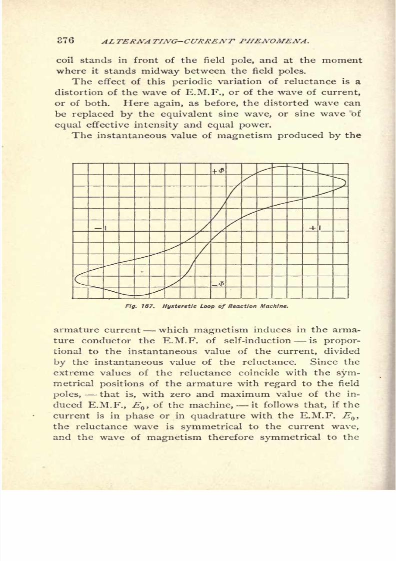
8/2/2019 Charles Steinmetz Theorycalculatio00steiiala
http://slidepdf.com/reader/full/charles-steinmetz-theorycalculatio00steiiala 402/557
J76 ALTERNA TING-CURRENT PHENOMENA.
coil stands in front of the field pole, and at the moment
where it stands midway between the field poles.
The effect of this periodic variation of reluctance is a
distortion of the wave of E.M.F., or of the wave of current,
or of both. Here again, as before, the distorted wave can
be replaced by the equivalent sine wave, or sine wave of
equal effective intensity and equal power.
The instantaneous value of magnetism produced by the
Fig. 167. Hysteretic Loop of Reaction Machine.
armature current which magnetism induces in the arma-
ture conductor the E.M.F. of self-induction is propor-
tional to the instantaneous value of the current, divided
by the instantaneous value of the reluctance. Since the
extreme values of the reluctance coincide with the sym-
metrical positions of the armature with regard to the field
poles, that is, with zero and maximum value of the in-
duced E.M.F., EQ ,of the machine, it follows that, if the
current is in phase or in quadrature with the E.M.F. EQ ,
the reluctance wave is symmetrical to the current wave,
and the wave of magnetism therefore symmetrical to the
8/2/2019 Charles Steinmetz Theorycalculatio00steiiala
http://slidepdf.com/reader/full/charles-steinmetz-theorycalculatio00steiiala 403/557
REACTION MACHINES. 377
current wave also. Hence the equivalent sine wave of
magnetism is of equal phase with the current wave ; that
is, the E.M.F. of self-induction lags 90 behind the cur-
rent, or is wattless.
Thus at no-phase displacement, and at 90 phase dis-
placement, a reaction machine can neither produce electri-
cal power nor mechanical power.
230. If, however, the current wave differs in phase
from the wave of E.M.F. by less than 90, but more than
zero degrees, it is unsymmetrical with regard to the
reluctance wave, and the reluctance will be higher for ris-
ing current than for decreasing current, or it will be
higher for decreasing than for rising current, according
to the
phase
relation of current with
regard
to induced
E.M.F., Q.
In the first case, if the reluctance is higher for rising,
lower for decreasing, current, the magnetism, which is pro-
portional to current divided by reluctance, is higher for
decreasing than for rising current;that is, its equivalent
sine wave lags behind the sine wave of current, and the
E.M.F. or self-induction will lag more than 90 behind thecurrent
;that is, it will consume electrical power, and
thereby deliver mechanical power, and do work as syn-
chronous motor.
In the second case, if the reluctance is lower for rising,
and higher for decreasing, current, the magnetism is higher
for rising than for decreasing current, or the equivalent sine
wave of magnetism leads the sine wave of the current, and
the counter E.M.F. at self-induction lags less than 90 be-
hind the current;that is, yields electric power as generator,
and thereby consumes mechanical power.
In the first case the reactance will be represented by
X = h jx, similar as in the case of hysteresis ;while in
the second case the reactance will be represented by
X = - h- jx.
8/2/2019 Charles Steinmetz Theorycalculatio00steiiala
http://slidepdf.com/reader/full/charles-steinmetz-theorycalculatio00steiiala 404/557
378 ALTERNATING-CURRENT PHENOMENA.
231. The influence of the periodical variation of reac-
tance will obviously depend upon the nature of the variation,
that is, upon the shape of the reactance curve. Since,
however, no matter what shape the wave has, it can always
be dissolved in a series of sine waves of double frequency,
and its higher harmonics, in first approximation the assump-
tion can be made that the reactance or the reluctance vary
with double frequency of the main current;that is, are
represented in the form,
x = a + b cos 2/8.
Let the inductance, or the coefficient of self-induction,
be represented by
L = I + < cos 2/3
=/(I + y COS 2 0)
where y=
amplitude of variation of inductance.
Let
u> = angle of lag of zero value of current behind maximum value
of inductance L.
It is then, assuming the current as sine wave, or repla-
cing it by the equivalent sine wave of effective intensity /,
Current,* = IV2 sin
(/?-
).
The magnetism produced by this current is,
where n = number of turns.
Hence, substituted,
sin(/?-
5) (1 + y cos 2 0),
or, expanded,
n
when neglecting the term of triple frequency, as wattless.

8/2/2019 Charles Steinmetz Theorycalculatio00steiiala
http://slidepdf.com/reader/full/charles-steinmetz-theorycalculatio00steiiala 405/557
REACTION MACHINES, 379
Thus the E.M.F. induced by this magnetism is,
hence, expanded
e = - 2 TT 7W7V2 !7 1 - 2\ cos cos /3 + /I + sn sn
IVZJ \
2
and the effective value of E.M.F.,
l + 2
= 2 TT NII\\ + -7 cos 2 a. ^
Hence, the apparent power, or the voltamperes
+-J
2
y COS 2 u>
The instantaneous value of power is
2
sin(/? c(,)f/l |\cos w cos
y3 +
sin eo sin/3 [.
.
7
and, expanded
sin 2 eo cos2
/3 + sin 2 /3(
cos 2 w 2\ 1
V2/J
Integrated, the effective value of power is
8/2/2019 Charles Steinmetz Theorycalculatio00steiiala
http://slidepdf.com/reader/full/charles-steinmetz-theorycalculatio00steiiala 406/557
380 ALTERNA TING-CURRENT PHENOMENA.
hence, negative, that is, the machine consumes electrical,
and produces mechanical, power, as synchronous motor, if
o> > ;that is, with lagging current; positive, that is, the
machine produces electrical, and consumes mechanical,
power, as generator, if to > ;that is, with leading current.
The power factor is
r j_ P_ _ y sin 2 ai
hence, a maximum, if,
d<
or, expanded, 1
cos2 = i
Thepower,
P, is a maximum at
givencurrent, /, if
sin 2 w = 1;
that is,
to = 45
at given E.M.F., E, the power is
p=__hence, a maximum at
or, expanded,
1 +1T
232. We have thus, at impressed E.M.F., E, and negli-
gible resistance, if we denote the mean value of reactance,
x=lTtNl.
Current
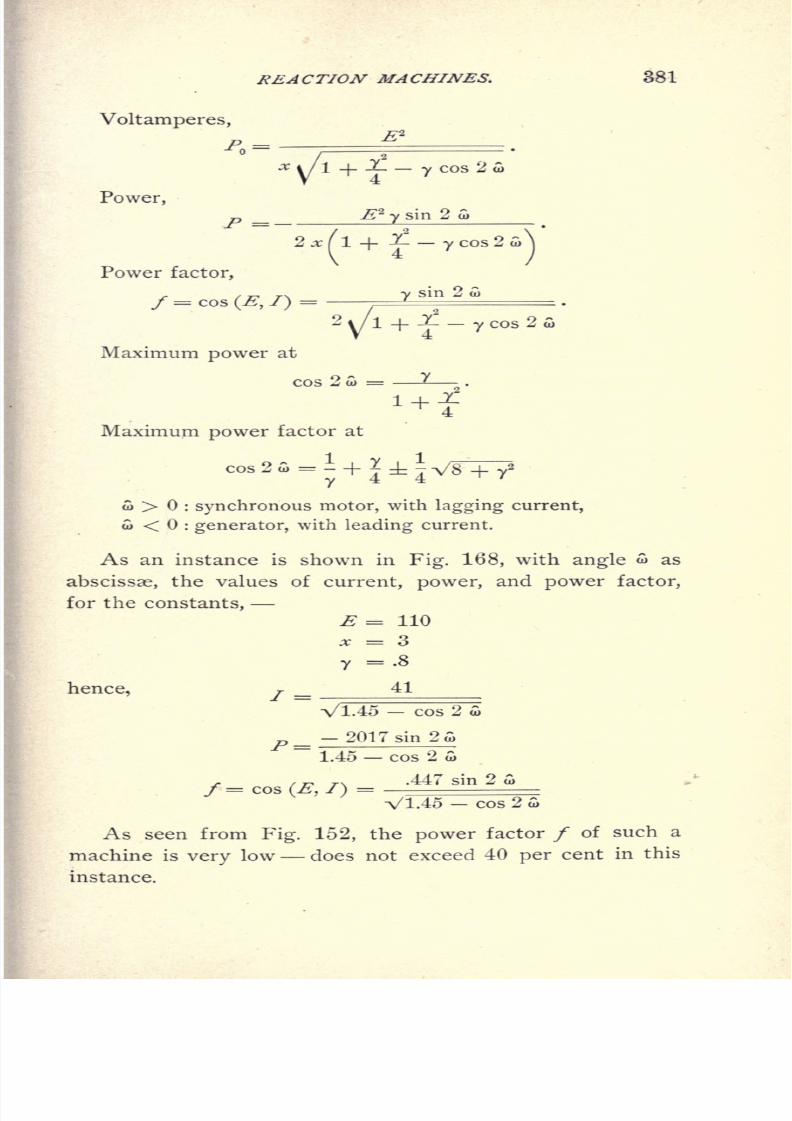
8/2/2019 Charles Steinmetz Theorycalculatio00steiiala
http://slidepdf.com/reader/full/charles-steinmetz-theorycalculatio00steiiala 407/557
REACTION MACHINES. 381
Voltamperes,
k-
Power,^g
2
y sin 2
2^fl+^--ycos2Power factor,
,. / 77 T-N y sin 2 to
f = cos (E, /)= '
2
y/l+
J^
_y cos 2 A
Maximum power at
*+iMaximum power factor at
to > : synchronous motor, with lagging current,
w < : generator, with leading current.
As an instance is shown in Fig. 168, with angle to as
abscissae, the values of current, power, and power factor,
for the constants,
E = 110
x = 3
y =.8
hence, j41
Vl.45 cos 2
- 2017 sin 2wP =
f= cos (E,I)
1.45 cos 2 w
.447 sin 2 G>
As seen from Fig. 152, the power factor / of such a
machine is
very
low does not exceed 40 per cent in this
instance.
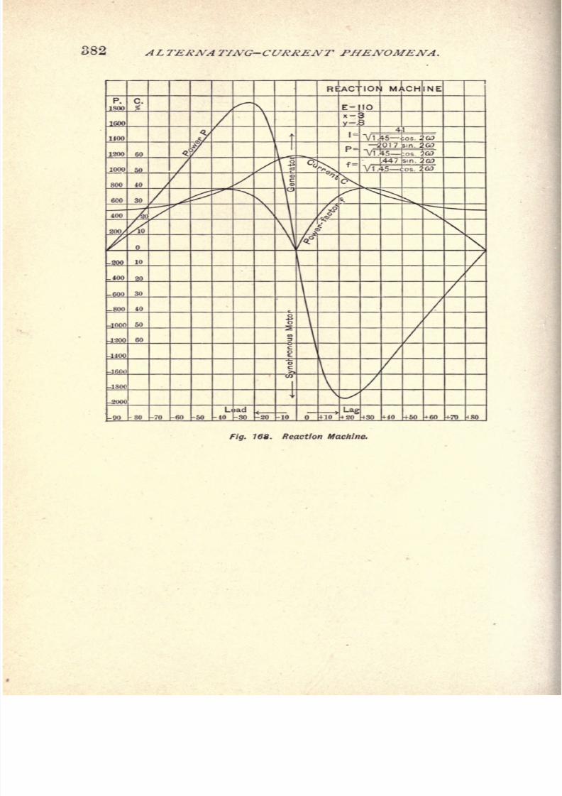
8/2/2019 Charles Steinmetz Theorycalculatio00steiiala
http://slidepdf.com/reader/full/charles-steinmetz-theorycalculatio00steiiala 408/557
382 ALTERNA TING-CURRENT PHENOMENA.
Fig. 188. Reaction Machine.
8/2/2019 Charles Steinmetz Theorycalculatio00steiiala
http://slidepdf.com/reader/full/charles-steinmetz-theorycalculatio00steiiala 409/557
DISTORTION OF WAVE-SHAPE. 383
CHAPTER XXII.
DISTORTION OF WAVE-SHAPE AND ITS CAUSES.
233. In the preceding chapters we have considered
the alternating currents and alternating E.M.Fs. as sine
waves or as replaced by their equivalent sine waves.
While this is sufficiently exact in most cases, under
certain circumstances the deviation of the wave from sine
shape becomes of importance, and with certain distortions
it may not be possible to replace the distorted wave by an
equivalent sine wave, since the angle of phase displacement
of the equivalent sine wave becomes indefinite. Thus it
becomes desirable to investigate the distortion of the wave,
its causes and its effects.
Since, as stated before, any alternating wave can be
represented by a series of sine functions of odd orders, the
investigation of distortion of wave-shape resolves itself in
the investigation of the higher harmonics of the alternating
wave.
In general we have to distinguish between higher har-
monics of E.M.F. and higher harmonics of current. Both
depend upon each other in so far as with a sine wave of
impressed E.M.F. a distorting effect will cause distortion
of the current wave, while with a sine wave of current
passing through the circuit, a distorting effect will cause
higher harmonics of E.M.F.
234. In a conductor revolving with uniform velocity
through a uniform and constant magnetic field, a sine wave
of E.M.F. is induced. In a circuit with constant resistance
and constant reactance, this sine wave of E.M.F. produces

8/2/2019 Charles Steinmetz Theorycalculatio00steiiala
http://slidepdf.com/reader/full/charles-steinmetz-theorycalculatio00steiiala 410/557
384 ALTERNATING-CURRENT PHENOMENA.
a sine wave of current. Thus distortion of the wave-shape
or higher harmonics may be due to:
lack of uniformity of
the velocity of the revolving conductor;lack of uniformity
or pulsation of the magnetic field; pulsation of the resis-
tance;or pulsation of the reactance.
The first two cases, lack of uniformity of the rotation or
of the magnetic field, cause higher harmonics of E.M.F. at
open circuit. The last, pulsation of resistance and reac-
tance, causes higher harmonics only with a current flowing
in the circuit, that is, under load.
Lack of uniformity of the rotation is of no practical in-
terest as cause of distortion, since in alternators, due to
mechanical momentum, the speed is always very nearly
uniform during the period.
Thus as causes of higher harmonics remain :
1st. Lack of uniformity and pulsation of the magnetic
field, causing a distortion of the induced E.M.F. at open
circuit as well as under load.
2d. Pulsation of the reactance, causing higher harmonics
under load.
3d. Pulsation of the resistance, causing higher harmonics
under load also.
Taking up the different causes of higher harmonics we
have :
Lack of Uniformity and Pulsation of tJie Magnetic Field.
235. Since most of the alternating-current generators
contain definite andsharply
defined field
poles covering
in
different types different proportions of the pitch, in general
the magnetic flux interlinked with the armature coil will
not vary as simply sine wave, of the form :
$ cos/?,
but as a complex harmonic function, depending on the shape
and the pitch of the field poles, and the arrangement of the
armature conductors. In this case, the magnetic flux issu-
8/2/2019 Charles Steinmetz Theorycalculatio00steiiala
http://slidepdf.com/reader/full/charles-steinmetz-theorycalculatio00steiiala 411/557
DISTORTION OF WAVE-SHAPE. 385
ing from the field pole of the alternator can be represented
by the general equation,
4> = A + A, cos /8 + A* cos 2(3 + Azcos 3/8 + . . .
+ ^ sin + -#2sin 2 + .#, sin 3
ft + . . .
If the reluctance of the armature is uniform in all directions,
so that the distribution of the magnetic flux at the field-pole
face does not change by the rotation of the armature, the
rate of cutting magnetic flux by an armature conductor is <,
and the E.M.F. induced in the conductor thus equal thereto
in wave shape. As a rule A,A
z,A
t. . . By B equal zero
;
that is, successive field poles are equal in strength and dis-
tribution of magnetism, but of opposite polarity. In some
types of machines, however, especially induction alternators,
this is not the case.
The E.M.F. induced in a full-pitch armature turn that
is, armature conductor and return conductor distant from
former by the pitch of the armature pole (corresponding to
the distance from field pole center to pole center) is,
8 = $ - 3>180
= 2 \Ai cos/3 + A
acos 3
(3 + A6cos 5 + . . .
+ BIsin
j3 + Bz
sin 3ft +
jB6sin 5
ft +. . .
\
Even with an unsymmetrical distribution of the magnetic
flux in the air-gap, the E.M.F. wave induced in a full-pitch
armature coil is symmetrical ;the positive and negative half
waves equal, and correspond to the mean flux distribution
of adjacent poles. With fractional pitch windings that
is, windings whose turns cover less than the armature pole
pitch the induced E.M.F. can be unsymmetrical with
unsymmetrical magnetic field, but as a rule is symmetrical
also. In unitooth alternators the total induced E.M.F. has
the same shape as that induced in a single turn.
With the conductors more or less distributed over the
surface of the armature, the total induced E.M.F. is the
resultant ofseveral E.M.Fs. of different phases, and
is thus
more uniformly varying ;that is, more sinusoidal, approaching
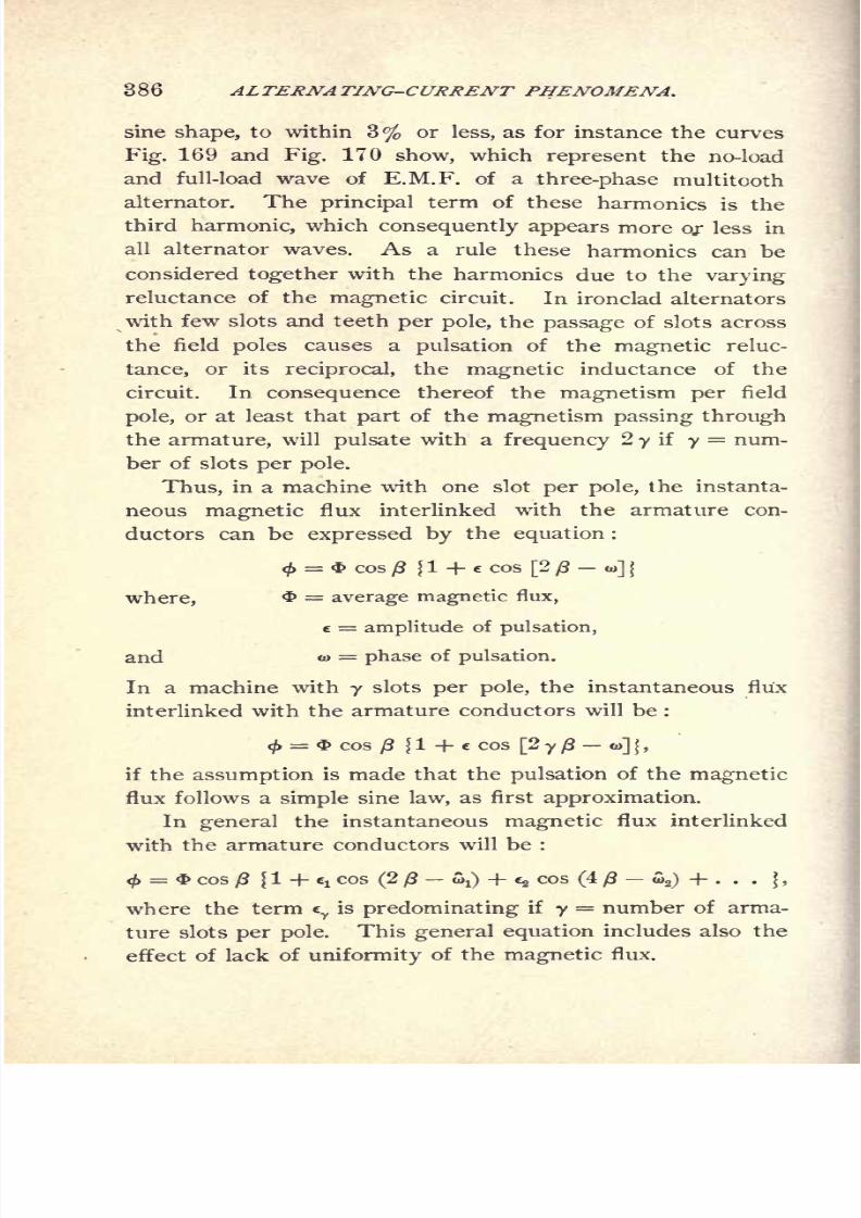
8/2/2019 Charles Steinmetz Theorycalculatio00steiiala
http://slidepdf.com/reader/full/charles-steinmetz-theorycalculatio00steiiala 412/557
386 ALTERNATING-CURRENT PHENOMENA.
sine shape, to within 3% or less, as for instance the curves
Fig. 169 and Fig. 170 show, which represent the no-load
and full-load wave of E.M.F. of a three-phase multitooth
alternator. The principal term of these harmonics is the
third harmonic, which consequently appears more or less in
all alternator waves. As a rule these harmonics can be
considered together with the harmonics due to the varying
reluctance of the magnetic circuit. In ironclad alternators
with few slots and teeth per pole, the passage of slots across
the field poles causes a pulsation of the magnetic reluc-
tance, or its reciprocal, the magnetic inductance of the
circuit. In consequence thereof the magnetism per field
pole, or at least that part of the magnetism passing through
the armature, will pulsate with a frequency 2 y if y= num-
ber of slots per pole.
Thus, in a machine with one slot per pole, the instanta-
neous magnetic flux interlinked with the armature con-
ductors can be expressed by the equation :
< = $ cos /? [1 + e cos [2 (3 o>] j
where, = average magnetic flux,
c = amplitude of pulsation,
and to = phase of pulsation.
In a machine with y slots per pole, the instantaneous flux
interlinked with the armature conductors will be :
<f>= & cos
/8 {1 + c cos [2 y ft o>] | ,
if theassumption
is made that thepulsation
of the
magneticflux follows a simple sine law, as first approximation.
In general the instantaneous magnetic flux interlinked
with the armature conductors will be :
^ = * cos {1 + 6!cos (2
-SO + e, cos (4
-oV,) + . . .
f ,
where the term ey
is predominating if y= number of arma-
ture slots
per pole.
Thisgeneral equation
includes also the
effect of lack of uniformity of the magnetic flux.
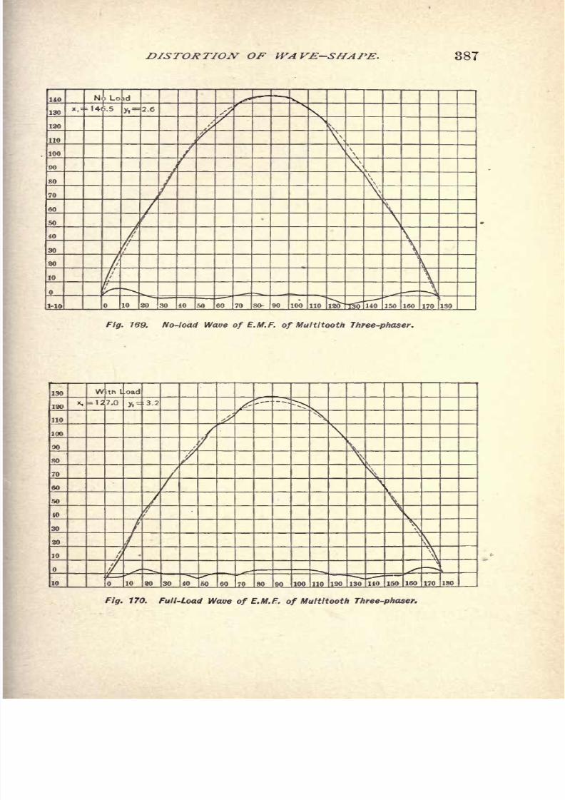
8/2/2019 Charles Steinmetz Theorycalculatio00steiiala
http://slidepdf.com/reader/full/charles-steinmetz-theorycalculatio00steiiala 413/557
DISTORTION OF WAVE-SHAPE. 387
Nil LoLd
,"14 .5y,
Fig. 169. No-load of E.M.F. of Multitooth Three-phaser.
Fig. 170. Full-Load Waue of E.M.F. of Multitooth Three-phaser.

8/2/2019 Charles Steinmetz Theorycalculatio00steiiala
http://slidepdf.com/reader/full/charles-steinmetz-theorycalculatio00steiiala 414/557
388 ALTERNATING-CURRENT PHENOMENA.
In case of a pulsation of the magnetic flux with the
frequency 2y,due to an existence of
yslots
per polein the
armature, the instantaneous value of magnetism interlinked
with the armature coil is :
< = $ COSft {1 + e COS [2 y ft ]}.
Hence the E.M.F. induced thereby :
e = n
dtd
*
And, expanded :
e= V27rA^<fc{sin/?+e-^= sin[(2y 1)-
J]
Hence, the pulsation of the magnetic flux with the
frequency 2 y, as due to the existence of y slots per pole,
introduces two harmonics, of the orders(2 y 1) and
(2 7+1).
236. If y = 1 it is :
e = V2 TTNn <i> (sin /3 + 1 sin (0 ) +^ sin (3 /? - )} ;
that is : In a unitooth single-phaser a pronounced triple
harmonic may be expected, but no pronounced higher
harmonics.
Fig. 171 shows the wave of E.M.F. of the main coil of
a monocyclic alternator at no load, represented by :
e = E (sin (3.242 sin
(3
/3 6.3) .046 sin (5/3- 2.6)
+ .068 sin (7 3.3) .027 sin (9 ft 10.0) .018 sin
(11 /3-
6.6) + .029 sin (13 ft-
8.2)};
hence giving a pronounced triple harmonic only, as expected.
If y= 2, it is :
e = V2 TTNn 4>
j
sin +
^sin (3 ft
-J) +
|f
sin (5 ft-
Si)
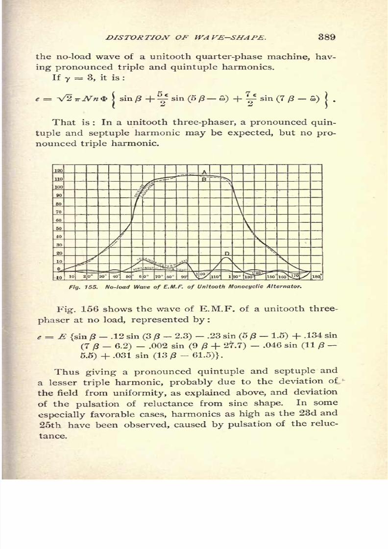
8/2/2019 Charles Steinmetz Theorycalculatio00steiiala
http://slidepdf.com/reader/full/charles-steinmetz-theorycalculatio00steiiala 415/557
DISTORTION OF WAVE-SHAPE. 389
the no-load wave of a unitooth quarter-phase machine, hav-
ing pronounced triple and quintuple harmonics.If 7
= 3, it is :
in/3+ sin(5j8 fi) + sin (7 ft-
S>)I .
That is : In a unitooth three-phaser, a pronounced quin-
tuple and septuple harmonic may be expected, but no pro-
nounced triple harmonic.
Fig. 155. No-load Wave of E.M.F. of Unitooth Monocyclic Alternator.
Fig. 156 shows the wave of E.M.F. of a unitooth three-
phaser at no load, represented by :
e = E (sin /3.12 sin (3 2.3) .23 sin (5 (3 1.5) + .134 sin
(7 ft_
6.2)- .002 sin (9 /3 + 27.7)
- .046 sin (11 /?
5.5) +.031 sin (13)8-61.5)}.
Thus giving a pronounced quintuple and septuple and
a lesser triple harmonic, probably due to the deviation of,
the field from uniformity, as explained above, and deviation
of the pulsation of reluctance from sine shape. In some
especially favorable cases, harmonics as high as the 23d and
25th have been observed, caused by pulsation of the reluc-

8/2/2019 Charles Steinmetz Theorycalculatio00steiiala
http://slidepdf.com/reader/full/charles-steinmetz-theorycalculatio00steiiala 416/557
390 ALTERNATING-CURRENT PHENOMENA.
V100
50 60 70 80 90 1 00 30 140 150 160 170 180
Fig. 172. No-load Wave of E.M.F. of Unitooth Three-phase Alternator.
In general, if the pulsation of the magnetic inductance
is denoted by the general expression :
l + ^"cY cos(2 yj8-aY),
1
the instantaneous magnetic flux is :
00
= $ cos 13 eycos (2 y ff
-
cos((2y+l)
hence, the E.M.F.
2;
sm (P

8/2/2019 Charles Steinmetz Theorycalculatio00steiiala
http://slidepdf.com/reader/full/charles-steinmetz-theorycalculatio00steiiala 417/557
DISTORTION OF WAVE-SHAPE. 391
Pulsationof
Reactance.
237. The main causes of a pulsation of reactance are :
magnetic saturation and hysteresis, and synchronous motion.
Since in an ironclad magnetic circuit the magnetism is not
proportional to the M.M.F., the wave of magnetism and
thus the wave of E.M.F. will differ from the wave of cur-
rent. As far as this distortion is due to the variation of
permeability, the distortion is symmetrical and the wave
of induced E.M.F. 'represents no power. The distortion
caused by hysteresis, or the lag of the magnetism behind
the M.M.F., causes an unsymmetrical distortion of the wave
which makes the wave of induced E.M.F. differ by more
than 90 from the current wave and thereby represents
power,the
powerconsumed
by hysteresis.In practice both effects are always superimposed ;
that
is, in a ferric inductance, a distortion of wave-shape takes
place due to the lack of proportionality between magnetism
and M.M.F. as expressed by the variation in the hysteretic
cycle.
This pulsation of reactance gives rise to a distortion
consisting mainly of a triple harmonic. Such current wavesdistorted by hysteresis, with a sine wave of impressed
E.M.F., are shown in Figs. 66 to 69, Chapter X., on Hy-
steresis. Inversely, if the current is a sine wave, the mag-
netism and the E.M.F. will differ from sine shape.
For further discussion of this distortion of wave-shape
by hysteresis, Chapter X. may be consulted.
238. Distortion of wave-shape takes place also by the
pulsation of reactance due to synchronous rotation, as dis-
cussed in chapter on Reaction Machines.
In Figs. 148 and 149, at a sine wave of impressed
E.M.F., the distorted current waves have been constructed.
Inversely, if a sine wave of current,
/ = / cos B,

8/2/2019 Charles Steinmetz Theorycalculatio00steiiala
http://slidepdf.com/reader/full/charles-steinmetz-theorycalculatio00steiiala 418/557
392 ALTERNATING-CURRENT PHENOMENA.
passes through a circuit of synchronously varying reac-
tance ; as for instance, the armature of a unitooth alterna-
tor or synchronous motor or, more general, an alternator
whose armature reluctance is different in different positions
with regard to the field poles and the reactance is ex-
pressed by
or, more general,
X=
the wave of magnetism is
X= x 1 + yr ^ cos (2 y ft- &
l
hence the wave of induced E.M.F.
= *sin/3 + sin ()8-
fflO +[e,
sin((2 y + 1)
sin ((2y+ l)/8 -,+!)]} ;
that is, the pulsation of reactance of frequency, 2y, intro-
duces two higher harmonics of the order (2y 1), and
(2y + l\If ^T=^l
,
=*{sin0+|sinG8-a)
+.|l
sin(3/J-o,)^
Since the pulsation of reactance due to magnetic satu-
ration and hysteresis is essentially of the frequency, 21V,
8/2/2019 Charles Steinmetz Theorycalculatio00steiiala
http://slidepdf.com/reader/full/charles-steinmetz-theorycalculatio00steiiala 419/557
DISTORTION OF WAVE-SHAPE. 393
that is, describes a complete cycle for each half-wave of
current, this shows why the distortion of wave-shape by
hysteresis consists essentially of a triple harmonic.
The phase displacement between e and i, and thus the
power consumed or produced in the electric circuit, depend
\ipon the angle, o>, as discussed before.
239. In case of a distortion of the wave-shape by
reactance, the distorted waves can be replaced by their
equivalent sine waves, and the investigation with suffi-
cient exactness for most cases be carried out under the
assumption of sine waves, as done in the preceding chapters.
Similar phenomena take place in circuits containing
polarization cells, leaky condensers, or other apparatus
representing
a
synchronously varyingnegative reactance.
Possibly dielectric hysteresis in condensers causes a dis-
tortion similar to that due to magnetic hysteresis.
Pulsation of Resistance.
240. To a certain extent the investigation of the effect
of
synchronous pulsation
of the resistance coincides with
that of reactance;
since a pulsation of reactance, when
unsymmetrical with regard to the current wave, introduces
an energy component which can be represented by an
" effective resistance."
Inversely, an unsymmetrical pulsation of the ohmic
resistance introduces a wattless component, to be denoted
by "effective reactance."
A typical case of a synchronously pulsating resistance is
represented in the alternating arc.
The apparent resistance of an arc depends upon the
current passing through the arc;
that is, the apparent
resistance Of the arc = Potential
difference^between
electrodesjg high
for small currents, low for large currents. Thus in an
alternating arc the apparent resistance will vary during

8/2/2019 Charles Steinmetz Theorycalculatio00steiiala
http://slidepdf.com/reader/full/charles-steinmetz-theorycalculatio00steiiala 420/557
304 ALTERNATING-CURRENT PHENOMENA.
every half-wave of current between a maximum value at
zero current and a minimum value at maximum current,
thereby describing a complete cycle per half-wave of cur-
rent.
Let the effective value of current passing through the
arc be represented by /.
Then the instantaneous value of current, assuming the
current wave as sine wave, is represented by
/ = 7V2sin/3;
and the apparent resistance of the arc, in first approxima-
tion, byR = r (1 + e cos 2
j8) ;
thus the potential difference at the arc is
e = iR = /V2Vsin/3(l -f e cos 2/3)
Hence the effective value of potential difference,
and the apparent resistance of the arc,
r.-f-ry/t-.+f
The instantaneous power consumed in the arc is,
Hence the effective power,

8/2/2019 Charles Steinmetz Theorycalculatio00steiiala
http://slidepdf.com/reader/full/charles-steinmetz-theorycalculatio00steiiala 421/557
DISTORTION OF WAVE-SHAPE. 395
The apparent power, or volt amperes consumed by the
arc, is,
thus the power factor of the arc,
that is, less than unity.
241. We find here a case of a circuit in which the
power factor that is, the ratio of watts to volt amperes
differs from unity without any displacement of phase ;
that is, while current and E.M.F. are in
phase
with each
other, but are distorted, the alternating wave cannot be
replaced by an equivalent sine wave;since the assumption
of equivalent sine wave would introduce a phase displace-
ment,
cos w =/
of an angle, w, whose sign is indefinite.
As an instance are shown, in Fig. 173 for the constants,
1= 12
r= 3
=.9the resistance,
R = 3{I + .9 cos 2
/3) ;
the current,* = 17 sin
/3 ;
tha potential difference,
e = 28(sin ft + .82 sin 3
).
In this case the effective E.M.F. is
=25.5;
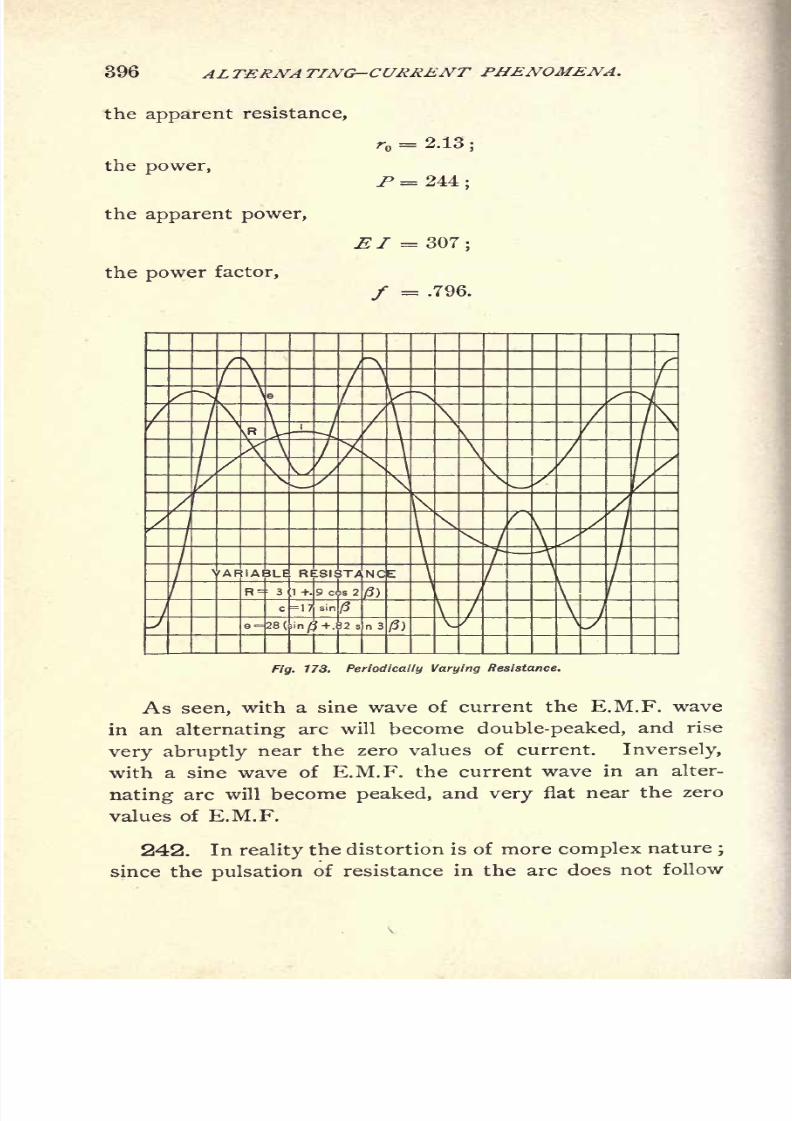
8/2/2019 Charles Steinmetz Theorycalculatio00steiiala
http://slidepdf.com/reader/full/charles-steinmetz-theorycalculatio00steiiala 422/557
396 ALTERNATING-CURRENT PHENOMENA.
the apparent resistance,
the power,
the apparent power,
the power factor,
r = 2.13 ;
P = 244;
El =307;
/ = .796.
Fig. 173. Periodically Varying Resistance.
As seen, with a sine wave of current the E.M.F. wave
in an alternating arc will become double-peaked, and rise
very abruptly near the zero values of current. Inversely,
with a sine wave of E.M.F. the current wave in an alter-
nating arc will become peaked, and very flat near the zero
values of E.M.F.
242. In reality the distortion is of more complex nature;
since the pulsation of resistance in the arc does not follow

8/2/2019 Charles Steinmetz Theorycalculatio00steiiala
http://slidepdf.com/reader/full/charles-steinmetz-theorycalculatio00steiiala 423/557
DISTORTION OF WAVE-SHAPE. 397
a simple sine law of double frequency, but varies much
more abruptly near the zero value of current, making
thereby the variation of E.M.F. near the zero value of
current much more abruptly, or, inversely, the variation
of current more flat.
A typical wave of potential difference, with a sine wave
of current passing through the arc, is given in Fig. 174.*
1 13 13 1 15
ONE PAIR CARBONSEG U LATE D BY HAND
A. C. dynamo e. m. f
' " "current*.
" " "watts.
7 18 19 20 S
Fig. 174. Electric Arc.
243. The value of e, the amplitude of the resistance
pulsation, largely depends upon the nature of the electrodes
and the steadiness of the arc, and with soft carbons and a
steady arc is small, and the power factor f of the arc near
unity. With hard carbons and an unsteady arc, e rises
greatly, higher harmonics appear in the pulsation of resis-
tance, and the power factor f falls, being in extreme cases
even as low as .6.
The conclusion to be drawn herefrom is, that photo-
metric tests of alternating arcs are of little value, if, besides
current and voltage, the power is not determined also by
means of electro-dynamometers.
*
From American Institute of Electrical Engineers, Transactions, 1890, p-
376. Tobey and Walbridge, on the Stanley Alternate Arc Dynamo.

8/2/2019 Charles Steinmetz Theorycalculatio00steiiala
http://slidepdf.com/reader/full/charles-steinmetz-theorycalculatio00steiiala 424/557
398 ALTERNA TING-CURRENT PHENOMENA .
CHAPTER XXIII.
EFFECTS OF HIGHER HARMONICS.
244. To elucidate the variation in the shape of alternat-
ing waves caused by various harmonics, in Figs. 175 and
Fig. 175. Effect of Triple Harmonic.
176 are shown the wave-forms produced by the superposi-
tion of the triple and the quintuple harmonic upon the
fundamental sine wave.
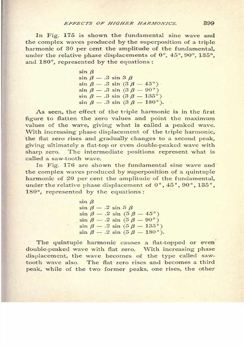
8/2/2019 Charles Steinmetz Theorycalculatio00steiiala
http://slidepdf.com/reader/full/charles-steinmetz-theorycalculatio00steiiala 425/557
EFFECTS OF HIGHER HARMONICS. 399
In Fig. 175 is shown the fundamental sine wave and
the complex waves produced by the superposition of a triple
harmonic of 30 per cent the amplitude of the fundamental,
under the relative phase displacements of 0, 45, 90, 135,
and 180, represented by the equations :
sinft
sinft
.3 sin 3ft
sin ft- .3 sin (3/3-45)sin ft
.3 sin (3 ft 90)s'm
ft- .3 sin (3 ft
-135)
sin ft.3 sin (3/3 180).
As seen, the effect of the triple harmonic is in the first
figure to flatten the zero values and point the maximum
values of the wave, giving what is called a peaked wave.
With increasing phase displacement of the triple harmonic,the flat zero rises and gradually changes to a second peak,
giving ultimately a flat-top or even double-peaked wave with
sharp zero. The intermediate positions represent what is
called a saw-tooth wave.
In Fig. 176 are shown the fundamental sine wave and
the complex waves produced by superposition of a quintuple
harmonic of 20 per cent the amplitude of the fundamental,
under the relative phase displacement of 0, 45, 90, 135,
180, represented by the equations :
sinft
sin ft.2 sin 5
ft
sin/3- .2 sin (5,8-45)
sin/3-.2 sin
(5/3-90)smft- .2 sin (5/3- 135)
sin/3- .2 sin (5/8- 180).
The quintuple harmonic causes a flat-topped or even
double-peaked wave with flat zero. With increasing phase
displacement, the wave becomes of the type called saw-
tooth wave also. The flat zero rises and becomes a third
peak, while of the two former peaks, one rises, the other

8/2/2019 Charles Steinmetz Theorycalculatio00steiiala
http://slidepdf.com/reader/full/charles-steinmetz-theorycalculatio00steiiala 426/557
400 AL TERNA TING-CURRENT PHENOMENA.
decreases, and the wave gradually changes to a triple-
peaked
wave with one mainpeak,
and a
sharpzero.
As seen, with the triple harmonic, flat-top or double-
peak coincides with sharp zero, while the quintuple har-
monic flat-top or double-peak coincides with flat zero.
Distortion of Wave Shapa
by Quintuple Harmonfc
Sin./S-.2sin.(5/?-S5j/
J\J
Fig. 176. Effect of Quintuple Harmonic.
Sharp peak coincides with flat zero in the triple, with
sharp zero in the quintuple harmonic. With the triple har-
monic, the saw-tooth shape appearing in case of a phase
difference between fundamental and harmonic is single,
while with the quintuple harmonic it is double.
Thus in general, from simple inspection of the wave
shape, the existence of these first harmonics can be discov-

8/2/2019 Charles Steinmetz Theorycalculatio00steiiala
http://slidepdf.com/reader/full/charles-steinmetz-theorycalculatio00steiiala 427/557
EFFECTS OF HIGHER HARMONICS. 401
Sin/?-.225 sinf3/?-180) ,
""-.05sin/5/3-180)
Sin./?- 15 sm.(3/?-180).
Sin./?-.15' sin 3/?-.1Q sir
(5/J-180)
f/jjr. 777. So/ne Characteristic Wave Shapes.
Flat top with flat zero :
sin/3
.15 sin 3/3
.10 sin 5 0.
Flat top with sharp zero :
sin - .225 sin (3 /3 - 180) - .05 sin (5 /3 - 180).Double peak, with sharp zero :
sin (3- .15 sin (30- 180)
- .10 sin 5/?.
Sharp peak with sharp zero :
sin {3.15 sin 3 .10 sin (5 (3 180).
245. Since the distortion of the wave-shape consists in
thesuperposition
of
higherharmonics, that is, waves of
higher frequency, the phenomena taking place in a circuit

8/2/2019 Charles Steinmetz Theorycalculatio00steiiala
http://slidepdf.com/reader/full/charles-steinmetz-theorycalculatio00steiiala 428/557
402 ALTERNATING-CURRENT PHENOMENA.
supplied by such a wave will be the combined effect of the
different waves.
Thus in a non-inductive circuit, the current and the
potential difference across the different parts of the circuit
are of the same shape as the impressed E.M.F. If self-
induction is inserted in series to a non-inductive circuit, the
self-induction consumes more E.M.F. of the higher harmon-
ics, since the reactance is proportional to the frequency,
and thus the current and the E.M.F. in the non-inductive
part of the circuit shows the higher harmonics in a reduced
amplitude. That is, self-induction in series to a non-induc-
tive circuit reduces the higher harmonics or smooths out
the wave to a closer resemblance with sine shape. In-
versely, capacity in series to a non-inductive circuit con-
sumes less
E.M.F.at
higherthan at
lower frequency, andthus makes the higher harmonics of current and of poten-
tial difference in the non-inductive part of the circuit more
pronounced intensifies the harmonics.
Self-induction and capacity in series may cause an in-
crease of voltage due to complete or partial resonance with
higher harmonics, and a discrepancy between volt-amperes
and watts, without corresponding phase displacement, as
will be shown hereafter.
246. In long-distance transmission over lines of notice-
able inductance and capacity, rise of voltage due to reso-
nance may occur with higher harmonics, as waves of higher
frequency, while the fundamental wave is usually of too low
a frequency to cause resonance.
An approximate estimate of the possible rise by reso-
nance with various harmonics can be obtained by the inves-
tigation of a numerical instance. Let in a long-distance
line, fed by step-up transformers at 60 cycles,
The resistance drop in the transformers at full load = 1%.
The inductance voltage in the transformers at full load = 5%

8/2/2019 Charles Steinmetz Theorycalculatio00steiiala
http://slidepdf.com/reader/full/charles-steinmetz-theorycalculatio00steiiala 429/557
EFFECTS OF HIGHER HARMONICS. 403
The inductance voltage in the line at full load = 20% with the
fundamental wave.
The capacity or charging current of the line = 20% of the full-
load current / at the frequency of the fundamental.
The line capacity may approximately be represented by
a condenser shunted across the middle of the line. The
E.M.F. at the generator terminals E is assumed as main-
tained constant.
The E.M.F. consumed by the resistance of the circuit
from generator terminals to condenser is
Ir = .06,
or, r = .06-|
.
The reactance E.M.F. between generator terminals and
condenser is, for the fundamental frequency,
Ix = .15,
-IK Eor, x = .15
,
thus the reactance corresponding to the frequency (2/ 1)
N of the higher harmonic is :
x(2k- 1) =.15(2- 1) .
The capacity current at fundamental frequency is :
hence, at the frequency : (2 k 1) N:
/ = .2(2-l)/Z,if:
e' = E.M.F. of the (2 k l)th harmonic at the condenser,
e = E.M.F. of the (2 k l)th harmonic at the generator terminals.
The E.M.F. at the condenser is :
e' = V*2 i a r2
+ ix (2k V)

8/2/2019 Charles Steinmetz Theorycalculatio00steiiala
http://slidepdf.com/reader/full/charles-steinmetz-theorycalculatio00steiiala 430/557
404 ALTERNA TING-CURRENT PHENOMENA.
hence, substituted :
' l .059856 (2k I)
2+ .0009 (2 k I)4
the rise of voltage by inductance and capacity.
Substituting :
k= 1 2 3 4 56or, 2 - 1 = 1 3 5 7 9 11
it is, a = 1.03 1.36 3.76 2.18 .70 .38
That is, the fundamental will be increased at open circuit
by 3 per cent, the triple harmonic by 36 per cent, the
quintuple harmonic by 276 per cent, the septuple harmonic
by 118 per cent, while the still higher harmonics are
reduced.
The maximum possible rise will take place for :
=0, or, 2,- 1 = 5.77
That is, at a frequency : N = 346, and a = 14.4.
That is, complete resonance will appear at a frequency
between quintuple and septuple harmonic, and would raise
the voltage at this particular frequency 14.4 fold.
If the voltage shall not exceed the impressed voltage by
more than 100 per cent, even at coincidence of the maximum
of the harmonic with the maximum of the fundamental,
the triple harmonic must be less than 70 per cent of the
fundamental,
the quintuple harmonic must be less than 26.5 per cent of the
fundamental,
the septuple harmonic must be less than 46 per cent of the
fundamental.
The voltage will not exceed twice the normal, even at
a frequency of complete resonance with the higher har-
monic, if none of the higher harmonics amounts to more

8/2/2019 Charles Steinmetz Theorycalculatio00steiiala
http://slidepdf.com/reader/full/charles-steinmetz-theorycalculatio00steiiala 431/557
EFFECTS OF HIGHER HARMONICS. 405
than 7 per cent, of the fundamental. Herefrom it follows
that the danger of resonance in high potential lines is in
general greatly over-estimated, since the conditions assumed
in this instance are rather more severe than found in prac-
tice, the capacity current of the line very seldom reaching
20% of the main current.
247. The power developed by a complex harmonic wave
in a non-inductive circuit is the sum of the powers of the
individual harmonics. Thus if upon a sine wave of alter-
nating E.M.F. higher harmonic waves are superposed, the
effective E.M.F., and the power produced by this wave in a
given circuit or with a given effective current, are increased.
In consequence hereof alternators and synchronous motors
of ironclad unitooth construction that is, machines giving
waves with pronounced higher harmonics give with the
same number of turns on the armature, and the same mag-
netic flux per field pole at the same frequency, a higher
output than machines built to produce sine waves.
248. This explains an apparent paradox :
If in the
three-phase
star-connected
generator
with the
magnetic field constructed as shown diagrammatically in
Fig. 162, the magnetic flux per pole = $, the number of
turns in series per circuit = n, the frequency= N, the
E.M.F. between any two collector rings is:
E= V2~7T^2;z<S>10-8.
since 2 armature turns simultaneously interlink with the
magnetic flux 3>.
The E.M.F. per armature circuit is :
hence the E.M.F. between collector rings, as resultant of
two E.M.Fs. e displaced by 60 from each other, is :

8/2/2019 Charles Steinmetz Theorycalculatio00steiiala
http://slidepdf.com/reader/full/charles-steinmetz-theorycalculatio00steiiala 432/557
406 ALTERNATING-CURRENT PHENOMENA.
while the same E.M.F. was found by direct calculation
from number of turns, magnetic flux, and frequency to be
equal to 2e; that is the two values found for the same
E.M.F. have the proportion V3 : 2 = 1 : 1.154.
Fig. 178. Three-phase Star-connected Alternator.
This discrepancy is due to the existence of more pro-
nouncedhigher
harmonics in the wave e than in the wave
E = e X V3, which have been neglected in the formula :
Hence it follows that, while the E.M.F. between two col-
lector rings in the machine shown diagrammatically in Fig.
178 is only e x V3, by massing the same number of turns
in one slot instead of in two slots, we get the E.M.F. 2 e
or 15.4 per cent higher E.M.F., that is, larger output.
8/2/2019 Charles Steinmetz Theorycalculatio00steiiala
http://slidepdf.com/reader/full/charles-steinmetz-theorycalculatio00steiiala 433/557
EFFECTS OF HIGHER HARMONICS. 407
It follows herefrom that the distorted E.M.F. wave of
a unitooth alternator is produced by lesser magnetic flux per
pole that is, in general, at a lesser hysteretic loss in the
armature or at higher efficiency than the same effective
E.M.F. would be produced with the same number of arma-
ture turns if the magnetic disposition were such as to pro-
duce a sine wave.
249. Inversely, if su<:h a distorted wave of E.M.F. is
impressed upon a magnetic circuit, as, for instance, a trans-
former, the wave of magnetism in the primary will repeat
in shape the wave of magnetism interlinked with the arma-
ture coils of the alternator, and consequently, with a lesser
maximum magnetic flux, the same effective counter E.M.F.
will be produced, that is, the same power converted in thetransformer. Since the hysteretic loss in the transformer
depends upon the maximum value of magnetism, it follows
that the hysteretic loss in a transformer is less with a dis-
torted wave of a unitooth alternator than with a sine wave.
Thus with the distorted waves of unitooth machines,
generators, transformers, and synchronous motors and
induction motors in so far as they are transformers
operate more efficiently.
250. From another side the same problem can be
approached.
If upon a transformer a sine wave of E.M.F. is im-
pressed, the wave of magnetism will be a sine wave also.
If now upon the sine wave of E.M.F. higher harmonics,
as sine waves of triple, quintuple, etc., frequency are
superposed in such a way that the corresponding higher
harmonic sine waves of magnetism do not increase the
maximum value of magnetism, or even lower it by a
coincidence of their negative maxima with the positive
maximum of thefundamental,
in this case all the
powerrepresented by these higher harmonics of E.M.F. will be

8/2/2019 Charles Steinmetz Theorycalculatio00steiiala
http://slidepdf.com/reader/full/charles-steinmetz-theorycalculatio00steiiala 434/557
408 ALTERNATING-CURRENT PHENOMENA.
transformed without an increase of the hysteretic loss, or
even with a decreased hysteretic loss.
Obviously, if the maximum of the higher harmonic wave
of magnetism coincides with the maximum of the funda-
mental, and thereby makes the wave of magnetism more
pointed, the hysteretic loss will be increased more than in
proportion to the increased power transformed, i.e., the
efficiency of the transformer will be lowered.
That is : Some distorted waves of E.M.F. are transformed
at a lesser, some at a larger, hysteretic loss than the sine
wave, if the same effective E.M.F. is impressed upon the
transformer.
The unitooth alternator wave and the first wave in Fig.
175 belong to the former class;the waves derived from
continuous-currentmachines, tapped
at twoequi-distant
points of the armature, in general, to the latter class.
251. Regarding the loss of energy by Foucault or eddy
currents, this loss is not affected by distortion of wave
shape, since the E.M.F. of eddy currents, as induced
E.M.F., is proportional to the secondary E.M.F.;and
thus at constant impressed primary E.M.F., the energyconsumed by eddy currents bears a constant relation to
the output of the secondary circuit, as obvious, since the
division of power between the two secondary circuits
the eddy current circuit, and the useful or consumer cir-
cuit is unaffected by wave-shape or intensity of mag-
netism.
252. In high potential lines, distorted waves whose
maxima are very high above the effective values, as peaked
waves, may be objectionable by increasing the strain on
the insulation. It is, however, not settled yet beyond
doubt whether the striking-distance of a rapidly alternat-
ing potential depends upon the maximum value or upon

8/2/2019 Charles Steinmetz Theorycalculatio00steiiala
http://slidepdf.com/reader/full/charles-steinmetz-theorycalculatio00steiiala 435/557
EFFECTS OF HIGHER HARMONICS. 409
some value between effective and maximum. Since dis-
ruptive phenomena do not always take place immediately
after application of the potential, but the time element plays
ari important part, it is possible that insulation-strain and
striking-distance is, in a certain range, dependent upon the
effective potential, and thus independent of the wave-shape.
In this respect it is quite likely that different insulating
materials show a different behavior, and homogeneous solid
substances, as paraffin, depend in their disruptive strength
upon the maximum value of the potential difference, while
heterogeneous materials, as mica, laminated organic sub-
stances, air, etc., that is substances in which the disruptive
strength decreases with the time application of the potential
difference, are less affected by very high peaks of E.M.F.
of
very
short duration.
In general, as conclusions may be derived that the im-
portance of a proper wave-shape is generally greatly over-
rated, but that in certain cases sine waves are desirable,
in other cases certain distorted waves are preferable.
8/2/2019 Charles Steinmetz Theorycalculatio00steiiala
http://slidepdf.com/reader/full/charles-steinmetz-theorycalculatio00steiiala 436/557
410 ALTERNATING-CURRENT PHENOMENA.
CHAPTER XXIV.
SYMBOLIC REPRESENTATION OF GENERALALTERNATING WAVES.
253. The vector representation,
A = a1
+y<zu = a (cos a -\-j sin
d)
of the alternating wave,
A a cos(< a)
applies to the sine wave only.
The general alternating wave, however, contains an in-
finite series of terms, of odd frequencies,
A = Alcos
(< #1) 4- Azcos (3 < #
3) + A&cos (5 < #
5) -f
thus cannot be directly represented by one complex vector
quantity.
The replacement of the general wave by its equivalent
sine wave, as before discussed, that is a sine wave of equal
effective intensity and equal power, whilesufficiently accu-
rate in many cases, completely fails in other cases, espe-
cially in circuits containing capacity, or in circuits containing
periodically (and in synchronism with the wave) varying
resistance or reactance (as alternating arcs, reaction ma-
chines, synchronous induction motors, oversaturated mag-
netic circuits, etc.).
Since, however, the individual harmonics of the general
alternating wave are independent of each other, that is, all
products of different harmonics vanish, each term can be
represented by a complex symbol, and the equations of the
general wave then are theresultants of those of the indi-
vidual harmonics.
8/2/2019 Charles Steinmetz Theorycalculatio00steiiala
http://slidepdf.com/reader/full/charles-steinmetz-theorycalculatio00steiiala 437/557
REPRESENTATION OF ALTERNATING WAVES. 411
This can be represented symbolically by combining in
one formula symbolic representations of different frequen-
cies, thus,00
A = .-i (a* +jn */)i
where,
and the index of the/M merely denotes that the/s of differ-
entindices n, while algebraically identical, physically rep-
resent different frequencies, and thus cannot be combined.
The general wave of E.M.F. is thus represented by,
the general wave of current by,
if,
is the impedance of the fundamental harmonic, where
xm is that part of the reactance which is proportional to
the frequency (inductance, etc.).
x is that part of the reactance which is independent of
the frequency (mutual induction, synchronous motion, etc.).
xc is that part of the reactance which is inversely pro-
portional to the frequency (capacity, etc.).
The impedance for the nth harmonic is,
r Jnn xm
This term can be considered as the general symbolic
expression of the
impedance
of a circuit of general wave
shape.

8/2/2019 Charles Steinmetz Theorycalculatio00steiiala
http://slidepdf.com/reader/full/charles-steinmetz-theorycalculatio00steiiala 438/557
412 ALTERNATING-CURRENT PHENOMENA.
Ohm's law, in symbolic expression, assumes for the
general alternating wave the form,
/-Jo,
E = IZ or,
Z = or,
Z = r - n
The symbols of multiplication and division of the terms
E, /, ^f, thus represent not algebraic operation, but multi-
plication and division of corresponding terms of E, T, Z,
that is, terms of the same index, or, in
algebraic multipli-cation and division of the series E, /, all compound terms,
that is terms containing two different w's, vanish.
254. The effective value of the general wave :
a = AI cos(< ,) + As
cos (3< a8) +^5
cos (5 <f>#6) +. .
is the
square
root of the sum of meansquares
of individual
harmonics,
A= V i { A? + A8
2 + A? + . . .|
Since, as discussed above, the compound terms, of two
different indices, vanish, the absolute value of the general
alternating wave,
8/2/2019 Charles Steinmetz Theorycalculatio00steiiala
http://slidepdf.com/reader/full/charles-steinmetz-theorycalculatio00steiiala 439/557
REPRESENTATION OF ALTERNATING WAVES. 413
is thus,
A
which offers an easy means of reduction from symbolic to
absolute values.
Thus, the absolute value of the E.M.F.
s,
the absolute value of the current,
is,
255. The double frequency power (torque, etc.) equa-
tion of the general alternating wave has the same symbolic
expression as with the sine wave :
= Pl
+JPJ
1
where,

8/2/2019 Charles Steinmetz Theorycalculatio00steiiala
http://slidepdf.com/reader/full/charles-steinmetz-theorycalculatio00steiiala 440/557
41-4 ALTERNATING-CURRENT PHENOMENA.
The jn enters under the summation sign of the " watt-
less power"
1$, so that the wattless powers of the different
harmonics cannot be algebraically added.
i Thus,
The total " true power" of a general alternating current
circuit is the algebraic sum of the powers of the individual
harmonics.
The total "wattless power" of a general alternating
current circuit is not the algebraic, but the absolute sum of
the wattless powers of the individual harmonics.
Thus, regarding the wattless power as a whole, in the
general alternating circuit no distinction can be made be-
tween lead and lag, since some harmonics may be leading,
others lagging.
The apparent power, or total volt-amperes, of the circuit
is,
The power factor of the circuit is,
The term "inductance factor," however, has no mean-
ing any more, since the wattless powers of the different
harmonics are not directly comparable.
The quantity,
,...._ ... wattless powerhas no physical significance, and is not
=
total apparent power

8/2/2019 Charles Steinmetz Theorycalculatio00steiiala
http://slidepdf.com/reader/full/charles-steinmetz-theorycalculatio00steiiala 441/557
REPRESENTATION OF ALTERNATING WAVES. 4] >
The term, /#.
El
=2/
n~ 1
7
where,
consists of a series of inductance factors qn of the individual
harmonics.
As a rule, if <f= 2^-1 ^n
2,
for the general alternating wave, that is q differs from
fo =vr^72
The complex quantity,
Q El~
El
1
takes in the circuit of the general alternating wave the
same position as power factor and inductance factor with
the sine wave.
p17= -~ may be called the "
circuitfactor"
It consists of a real term /, the power factor, and a
series of
imaginaryterms
jn qn, the inductancefactors of
the individual harmonics.

8/2/2019 Charles Steinmetz Theorycalculatio00steiiala
http://slidepdf.com/reader/full/charles-steinmetz-theorycalculatio00steiiala 442/557
416 ALTERNATING-CURRENT PHENOMENA.
The absolute value of the circuit factor :
as a rule, is < 1.
256. Some applications of this symbolism will explain
its mechanism and its usefulness more fully.
\st Instance : Let the E.M.F.,
be impressed upon a circuit of the impedance,
7 ( *CN
Z = *./ \nxm --that is, containing resistance r, inductive reactance xm and
capacity reactance xc in series.
Let
e? = 720 ef = 540
V= 283 4" = - 283
e = - 104 *6
" = 138
or,
^ = 900 tan e^= .75
*,= 400 tan o)
3= - 1
^5= 173 tan w
5= - 1.33
It is thus in symbolic expression,
Zj= 10 + 80/; *!
= 80.6
Z3= 10 z
z= 10
ZB= 10 - 32/; 2
5= 33.5
and, E.M.F.,
^ =(720 + 540/0 + (283
-283y;) + (- 104 + 138/5)
or absolute,
E = 1000
8/2/2019 Charles Steinmetz Theorycalculatio00steiiala
http://slidepdf.com/reader/full/charles-steinmetz-theorycalculatio00steiiala 443/557
REPRESENTATION OF ALTERNATING WAVES. 417
and current,
_ _ 720 + 540/t283 - 283/8
- 104 + 138./;
Z~~ 10 + 80/i
"
10 10-32y5
=(7.76
-8.04/i) + (28.3
-28.3/8) + (- 4.86 - 1.73A)
or, absolute,
7=41.85
of which is of fundamentalfrequency,
ll
= 11.15
" " " "triple
"I3= 40
quintuple"
I5= 5.17
The total apparent power of the circuit is,
Q = 7=41,850
The true power of the circuit is :
/ = [7i 7]1
= 1240 + 16,000 + 270
= 17,510
the wattless power,
j PJ =/ [7i 7]J= 10,000^
-850/6
thus, the total power,
P= 17,510
+ 10,000/;
-850y
5
That is, the wattless power of the first harmonic is
leading, that of the third harmonic zero, and that of the fifth
harmonic lagging.
17,510 = I2
r, as obvious.
The circuit factor is,
Q El= .418 + .239 j\
-.0203/5
or, absolute,
u = V.4182 + .2392 + .0203
2
= .482
The power factor is,
=

8/2/2019 Charles Steinmetz Theorycalculatio00steiiala
http://slidepdf.com/reader/full/charles-steinmetz-theorycalculatio00steiiala 444/557
418 ALTERNATING-CURRENT PHENOMENA.
The inductance factor of the first harmonic is :
ql
=.239,
that of the third harmonic ft=
0, and of the fifth harmonic
ft= - -0203.
Considering the waves as replaced by their equivalent
sine waves, from the sine wave formula,
f + qf = 1
the inductance factor wouldbe,
ft= -914
and the phase angle,
tan a, = ^= '-^=2.8= 65.4
p .41o
giving apparently a very great phase displacement, while in
reality, of the 41.85 amperes total current, 40 amperes (the
current of the third harmonic) are in phase with their
E.M.F.
We thus have here a case of a circuit with complex har-
monic waves which cannot be represented by their equiva-
lent sine waves. The relative magnitudes of the different
harmonics in the wave of current and of E.M.F. differ
essentially, and the circuit has simultaneously a very low
power factor and a very low inductance factor; that is, a low
power factor exists without corresponding phase displace-
ment, the circuit factor being less than one-half.
Such circuits, for instance, are those including alternat-
ing arcs, reaction machines, synchronous induction motors,
reactances with over-saturated magnetic circuit, high poten-
tial lines in which the maximum difference of potential ex-
ceeds the voltage at which brush discharges begin, polariza-
tion cells, and in general electrolytic conductors above the
dissociation voltage of the electrolyte, etc. Such circuits
cannot correctly, and in many cases not even approxi-
mately, be treated by the theory of the equivalent sine
waves, but require the symbolism of the complex harmonic
8/2/2019 Charles Steinmetz Theorycalculatio00steiiala
http://slidepdf.com/reader/full/charles-steinmetz-theorycalculatio00steiiala 445/557
REPRESENTATION OF ALTERNATING WAVES. 419
257. 2d instance: A condenser ofcapacity C = 20
m.f. is connected into the circuit of a 60-cycle alternator
giving a wave of the form,
e = E (cos <- .10 cos 3 <
- .08 cos 5<f> + .06 cos 7 <)
or, in symbolic expression,
= e(! 1-
.10,- .085 + .06
7)
The synchronous impedance of the alternator is,
ZQ = r jnnx = .3 5 njn
What is the apparent capacity C of the condenser(as cal-
culated from its terminal volts and amperes) when connected
directly with the alternator terminals, and when connected
thereto through various amounts of resistance and induc-
tive reactance.
The capacity reactance of the condenser is,
106
or, in symbolic expression,
Let
Z^ =.r jn nv = impedance inserted in series with the
condenser.
The total impedance of the circuit is then,
n
The current in the circuit is,
(.3 + r)- j (x
-132) (.3 + r) -j3 (3 x
-29)
^8 ^6 -j
+ + +
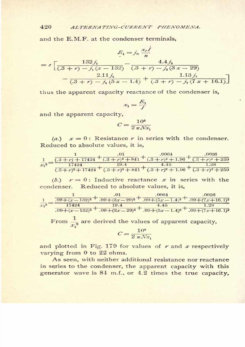
8/2/2019 Charles Steinmetz Theorycalculatio00steiiala
http://slidepdf.com/reader/full/charles-steinmetz-theorycalculatio00steiiala 446/557
420 ALTERNATING-CURRENT PHENOMENA.
and the E.M.F. at the condenser terminals,
;Jn V
4.4js
(.3 + r) -A (x-
132) (.3 + r)-jz (3 *
-29)__2.iiy5 1.13;; -i
(.3 + r) -j6 (5x- 1.4)
^(.3 + r) -/7 (7 x + 16.1)J
thus the apparent capacity reactance of the condenser is,
and the apparent capacity,
106
^.) ^r = : Resistance r in series with the condenser.
Reduced to absolute values, it is,
1 .01 .0064 .0036
17424 19.4
(.8+r)a+ 17424 (.3 +r)
2+ 841 (.3+ r)2+ 1.96 (.3 -f r)
2 +2
(.) r = : Inductive reactance x in series with the
condenser. Reduced to absolute values, it is,
1 .01 .0064 __ .0036
1.42 "*".1.4)2 .09+(7;r-f 16.
132)2 .
From g are derived the values of apparent capacity,
c=
and plotted in Fig. 179 for values of r and x respectively
varying from to 22 ohms.
As seen, with neither additional resistance nor reactance
inseries to the condenser, the apparent capacity with this
generator wave is 84 m.f., or 4.2 times the true
8/2/2019 Charles Steinmetz Theorycalculatio00steiiala
http://slidepdf.com/reader/full/charles-steinmetz-theorycalculatio00steiiala 447/557
REPRESENTATION OF ALTERNATING WAVES. 421
and gradually decreases with increasing series resistance, to
C= 27.5 m.f. = 1.375 times the true capacity at r= 13.2
ohms, or TV the true capacity reactance, with r = 132 ohms,
or with an additional resistance equal to thecapacity reac-
tance, C = 20.5 m.f. or only 2.5% in excess of the true
capacity C ,and at r = oo
,C = 20,3 m.f. or 1.5% in excess
of the true capacity.
With reactances, but no additional resistance r in
series,the apparent capacity C rises from 4.2 times the true
capacity at x = 0, to a maximum of 5,03 times the true
capacity, or C= 100.6 m.f. at x = .28, the condition of res-
onance of the fifth harmonic, then decreases to a minimum
of 27 m.f., or 35 % in excess of the true capacity, rises again
to 60.2 m.f., or 3.01 times the true capacity at x = 9.67,
the condition of resonance with the third harmonic, and
finally decreases, reaching 20 m.f., or the true capacity at
x = 132, or an inductive reactance equal to the capacity
reactance, then increases again to 20.2 m.f. at x = oo .
This rise and fall of the apparent capacity is within cer-
tain limits independent of the magnitude of the higher
harmonics of the generator wave of E.M.F., but merely de-
pends upon their presence. That is, with such a reactance
connected in series as to cause resonance with one of the
higher harmonics, the increase of apparent capacity is ap-
proximately the same, whatever the value of the harmonic,
whether it equals 25% of the fundamental or less than 5%,
provided the resistance in the circuit is negligible. The
only
effect of the amplitude of the higher harmonic is that
when it is small, a lower resistance makes itself felt by re-
ducing the increase of apparent capacity below the value it
would have were the amplitude greater.
It thus follows that the true capacity of a condenser
cannot even approximately be determined by measuring
volts and amperes if there are any higher harmonics present
in the generator wave, except by inserting a very largere-
sistance or reactance in series to the condenser.

8/2/2019 Charles Steinmetz Theorycalculatio00steiiala
http://slidepdf.com/reader/full/charles-steinmetz-theorycalculatio00steiiala 448/557
422 ALTERNATING-CURRENT PHENOMENA.
258. d instance : An alternating current generator
of the wave,
E. = 2000[l t + .12,
- .23B-
.13,]
and of synchronous impedance,
Z = .3-5*/;
feeds over a line of impedance,
a synchronous motor of the wave,
EI = 2250 [(cos oj +/i sin) + .24 (cos 3 w -(-y's
sin 3 o>)]
and of synchronous impedance,
Z2= .3 - C /;
The total impedance of the system is then,
Z = ZQ + Zl + Z2
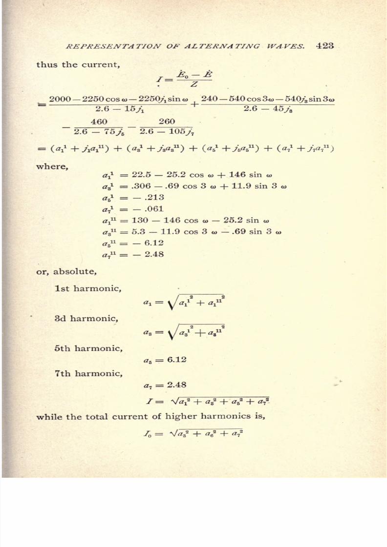
8/2/2019 Charles Steinmetz Theorycalculatio00steiiala
http://slidepdf.com/reader/full/charles-steinmetz-theorycalculatio00steiiala 449/557
REPRESENTATION OF ALTERNATING WAVES. 423
thus the current,
_ 2000- 2250 cos o>-
2250/\ sin o> 240- 540 cos 3a>- 540/; sin 3a>
2.6 - 15/i 2.6 - 45y8
460 260~~
2.6 - 75j\ 2.6 - 105jj
=
where,
aj1 = 22.5 - 25.2 cos co + 146 sin a>
ag1 = .306 - .69 cos 3 to + 11.9 sin 3
a,1 = - .213
7
i
= - .061
V1 = 130 - 146 cos w - 25.2 sin a>
^8= 5.3 - 11.9 cos 3 o>
- .69 sin 3 o>
a* = - 6.12
a7
u = - 2.48
or, absolute,
1st harmonic,
3d harmonic,
5thharmonic,
a6= 6.12
7th harmonic,
7= 2.48
/= V
while the total current of higher harmonics is,
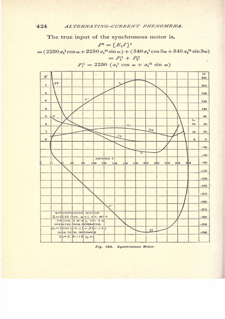
8/2/2019 Charles Steinmetz Theorycalculatio00steiiala
http://slidepdf.com/reader/full/charles-steinmetz-theorycalculatio00steiiala 450/557
424 ALTERNATING-CURRENT PHENOMENA.
The true input of the synchronous motor is,
=(2250 a cos o>+2250a? sin o>
)+ (540 a?cos 3o>+540 a
s
nsin 3o>)
= /V + /'s1
^ = 2250 (a? cos <o + af sino>)
. 780. Synchronous Motor,
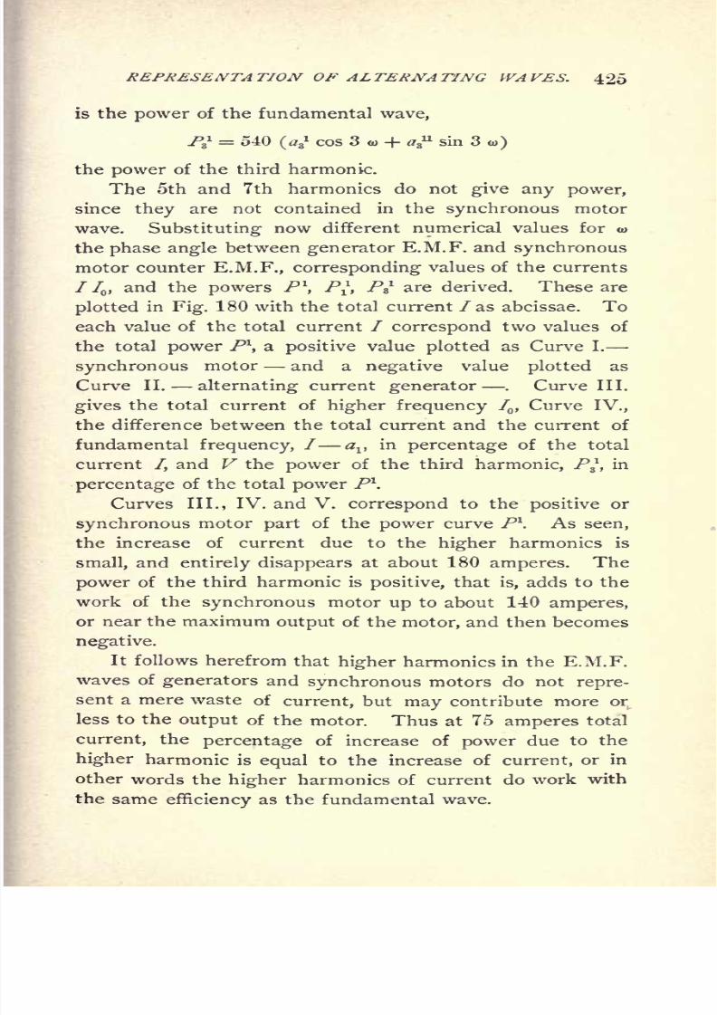
8/2/2019 Charles Steinmetz Theorycalculatio00steiiala
http://slidepdf.com/reader/full/charles-steinmetz-theorycalculatio00steiiala 451/557
REPRESENTATION OF ALTERNATING WAVES. 425
is the power of the fundamental wave,
P = 540(a,,
1cos 3 w + as
11sin 3
o>)
the power of the third harmonic.
The 5th and 7th harmonics do not give any power,
since they are not contained in the synchronous motor
wave. Substituting now different numerical values for u>
the phase angle between generator E.M.F. and synchronous
motor counter E.M.F., corresponding values of the currents
/ 7,and the powers P\ P*, /Y are derived. These are
plotted in Fig. 180 with the total current /as abcissae. To
each value of the total current / correspond two values of
the total power P\ a positive value plotted as Curve I.
synchronous motor and a negative value plotted as
Curve II. alternating current generator.
Curve III.
gives the total current of higher frequency I,Curve IV.,
the difference between the total current and the current of
fundamental frequency, / alt
in percentage of the total
current /, and V the power of the third harmonic, Pj, in
percentage of the total power P1.
Curves III., IV. and V. correspond to the positive or
synchronous motor part of the power curve P\ As seen,
the increase of current due to the higher harmonics is
small, and entirely disappears at about 180 amperes. The
power of the third harmonic is positive, that is, adds to the
work of the synchronous motor up to about 140 amperes,
or near the maximum output of the motor, and then becomes
negative.
It follows herefrom that higher harmonics in the E.M.F.
waves of generators and synchronous motors do not repre-
sent a mere waste of current, but may contribute more or
less to the output of the motor. Thus at 75 amperes total
current, the percentage of increase of power due to the
higher harmonic is equal to the increase of current, or in
other words the higher harmonics of current do work withthe same as the fundamental wave.
8/2/2019 Charles Steinmetz Theorycalculatio00steiiala
http://slidepdf.com/reader/full/charles-steinmetz-theorycalculatio00steiiala 452/557
426 ALTERNATING-CURRENT PHENOMENA.
259. kth Instance: In a small three-phase induction
motor, the constants per delta circuit are
Primary admittance Y= .002 + .03/
Self-inductive impedance ZQ= Z
l= .6 2.4/
and a sine wave of E.M.F. e = 110 volts is impressed upon
the motor.
The power output P, current input 7S ,and power factor
/, as function of the slip s are given in the first columns of
the following table, calculated in the manner as described in
the chapter on Induction Motors.
To improve the power factor of the motor and bring it
to unity at an output of 500 watts, a condenser capacity is
required giving 4.28 amperes leading current at 110 volts,
that is, neglecting the energy loss in the condenser, capacity
susceptance
In this case, let Is = current input into the motor per
delta circuit at slip s, as given in the following table.
The total current supplied by the circuit with a sine
wave of impressed E.M.F., is
/i = ls - 4.28/
energy currentand herefrom the power factor =-;
, given intotal current
the second columns of the table.
If the impressed E.M.F. is not a sine wave but a wave
of the shape
E,=
e, (l x
+ .12.
- .235
-.134,)
to give the same output, the fundamental wave must be the
same : e = 110 volts, when assuming the higher harmonics
in the motor as wattless, that is
= 110, + 13.2,-
25.3B-
14.7,
=*o + <?
where
l
= 13.2,
- 25.3B
- 14.7T
= component of impressed E.M.F. of higher frequency-
8/2/2019 Charles Steinmetz Theorycalculatio00steiiala
http://slidepdf.com/reader/full/charles-steinmetz-theorycalculatio00steiiala 453/557
REPRESENTATION^ Of ALTERNATING WAVES. 427
The effective value is :
EQ = 114.5 volts.
The condenser admittance for the general alternating
wave is
Yc= -.039/;
Since the frequency of rotation of the motor is very
small compared with the frequency of the higher harmonics,
as total impedance of the motor for these higher harmonics
can be assumed the stationary impedance, and by neglecting
the resistance it is
Z 1 = -njn (XQ + XJ
= - 4.8 njn
The exciting admittance of the motor, for these higher
harmonics, is, by neglecting the conductance,
n
and the higher harmonics of counter E.M.F.
Thus we have,
Current input in the condenser,
fc = E, Yc= -
4.28/i-
1.54/3 + 4.93/5 + 4.02/7
High frequency component of motor impedance current,
|=
.92/3-
1.06y5-
.44/7
High frequency component of motor exciting current,
=.07/3
--08/5
-.
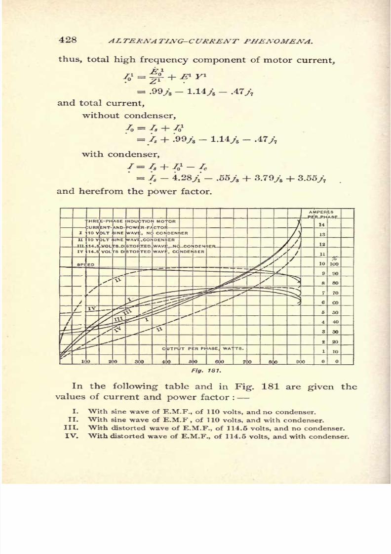
8/2/2019 Charles Steinmetz Theorycalculatio00steiiala
http://slidepdf.com/reader/full/charles-steinmetz-theorycalculatio00steiiala 454/557
428 ALTERNATING-CURRENT PHEA'OAIENA.
thus, total high frequency component of motor current,
/o1 =
|f+ & y1
= .99y3-
1.14,;-
.47/7
and total current,
without condenser,
4 = 4 + 41
= Is + .99/3-
1.14,;-
.47/7
with condenser,
= 4 -4.28,i
-.
and herefrom the power factor.
3.79,; + 3.55/7
T PER PHASE
In the following table and in Fig. 181 are given the
values of current and power factor :
I. With sine wave of E.M.F., of 110 volts, and no condenser.
II. With sine wave of E.M.F,of 1 10 volts, and with condenser.
III. With distorted wave of E.M.F., of 114.6 volts, and no condenser.
IV. With distorted wave of E.M.F., of 114.5 volts, and with condenser.

8/2/2019 Charles Steinmetz Theorycalculatio00steiiala
http://slidepdf.com/reader/full/charles-steinmetz-theorycalculatio00steiiala 455/557
REPRESENTATION OF ALTERNATING WAVES. 429
The curves II. and IV. with condenser are plotted in
dotted lines in Fig. 181. As seen, even with such a dis-
torted wave the current input and power factor of the motor
are not much changed if no condenser is used. When using
a condenser in shunt to the motor, however, with such awave of impressed E.M.F. the increase of the total current,
due to higher frequency currents in the condenser, is greater
than the decrease, due to the compensation of lagging cur-
rents, and the power factor is actually lowered by the con-
denser, over the total range of load up to overloads, and
especially at light loads.
Where a compensator or transformer is used for feeding-
the condenser, due to the internal self-induction of the com-
pensator, the higher harmonics of current are still more
accentuated, that is the power factor still more lowered.
In the preceding the energy loss in the condenser and
compensator and that due to the higher harmonics of cur-
rent in the motor has been neglected. The effect of this
energy loss is a slight decrease of efficiency and correspond-
ing increase of power factor. The power produced by the
higher harmonics has also been neglected ;it may be posi-
tive or negative, according to the index of the harmonic,
and the winding of the motor primary. Thus for instance,
the effect of the triple harmonic is negative in the quarter-
phase motor, zero in the three-phase motor, etc., altogether,,
however, the effect of these harmonics is very small.

8/2/2019 Charles Steinmetz Theorycalculatio00steiiala
http://slidepdf.com/reader/full/charles-steinmetz-theorycalculatio00steiiala 456/557
430 ALTERNATING-CURRENT PHENOMENA.
CHAPTER XXV.
GENERAL POLYPHASE SYSTEMS.
260. A polyphase system is an alternating-current sys-
tem in which several E.M.Fs. of the same frequency, but
displaced in phase from each other, produce several currents
of equal frequency, but displaced phases.
Thus any polyphase system can be considered as con-
sisting of a number of single circuits, or branches of the
polyphasesystem, which
may
be more or less interlinked
with each other.
In general the investigation of a polyphase system is
carried out by treating the single-phase branch circuits
independently.
Thus all the discussions on generators, synchronous
motors, induction motors, etc., in the preceding chapters,
apply to single-phase systems as well as polyphase systems,in the latter case the total power being the sum of the
powers of the individual or branch circuits.
If the polyphase system consists of n equal E.M.Fs.
displaced from each other by 1/n of a period, the system
is called a symmetrical system, otherwise an unsymmetrical
system.
Thus the three-phase system, consisting of three equal
E.M.Fs. displaced by one-third of a period, is a symmetrical
system. The quarter-phase system, consisting of two equal
E.M.Fs. displaced by 90, or one-quarter of a period, is an
unsymmetrical system.
261. The flow of power in a single-phase system is
pulsating ;that is, the watt curve of the circuit is a sine
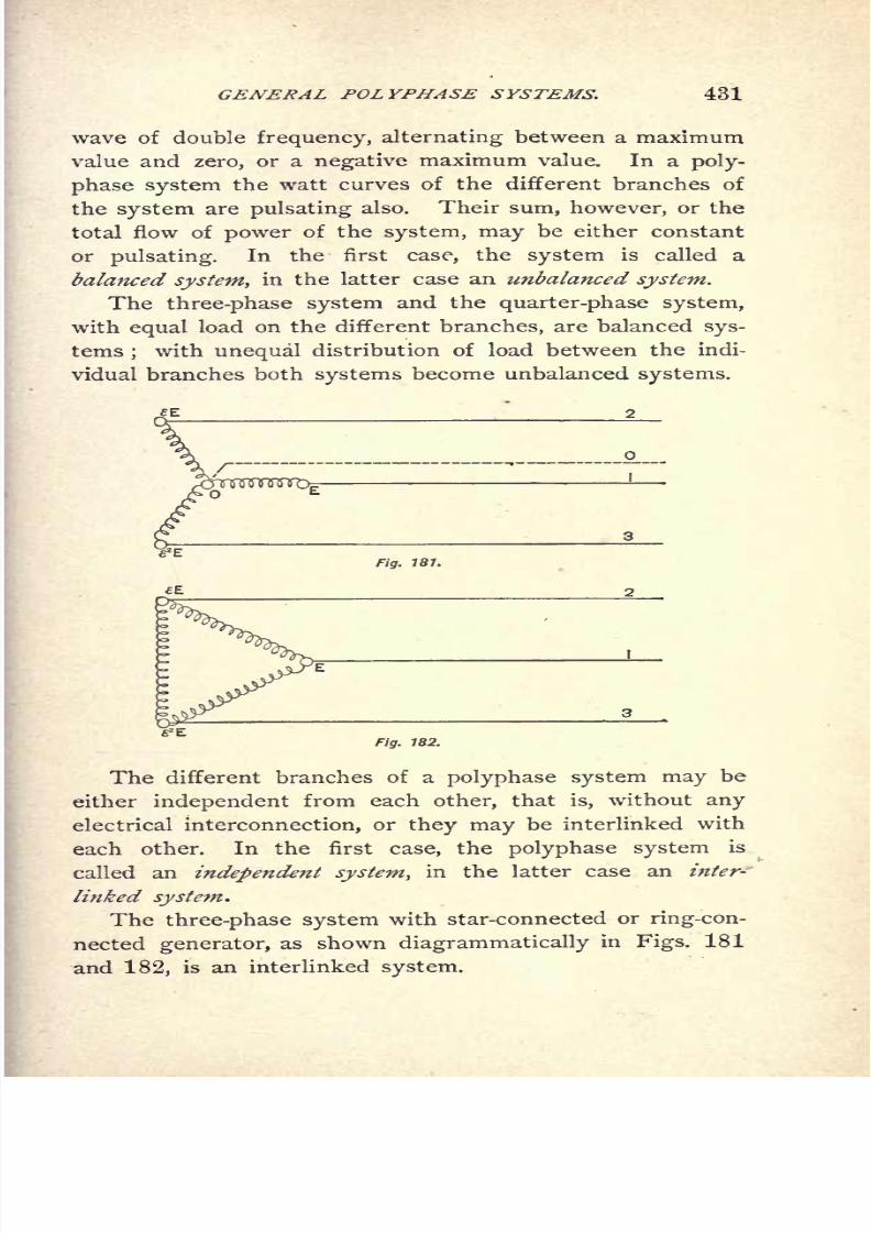
8/2/2019 Charles Steinmetz Theorycalculatio00steiiala
http://slidepdf.com/reader/full/charles-steinmetz-theorycalculatio00steiiala 457/557
GENERAL POLYPHASE SYSTEMS, 431
wave of double frequency, alternating between a maximum
value and zero, or a negative maximum value. In a poly-
phase system the watt curves of the different branches of
the system are pulsating also. Their sum, however, or the
total flow of power of the system, may be either constant
or pulsating. In the first case, the system is called a
balanced system, in the latter case an unbalanced system.
The three-phase system and the quarter-phase system,
with equal load on the different branches, are balanced sys-
tems;with unequal distribution of load between the indi-
vidual branches both systems become unbalanced systems.
Fig. 181.
Fig. 182.
The different branches of a polyphase system may be
either independent from each other, that is, without any
electrical interconnection, or they may be interlinked with
each other. In the first case, the polyphase system is
called an independent system, in the latter case an inter-
linked system.
The three-phase system with star-connected or ring-con-
nectedgenerator,
as showndiagrammatically
in Figs. 181
and 182, is an interlinked system.

8/2/2019 Charles Steinmetz Theorycalculatio00steiiala
http://slidepdf.com/reader/full/charles-steinmetz-theorycalculatio00steiiala 458/557
432 ALTERNATING-CURRENT PHENOMENA.
The four-phase system as derived by connecting four
equidistant points of a continuous-current armature with
four collector rings, as shown diagrammatically in Fig. 183,
Fig. 183.
is an interlinked system also. The four-wire quarter-phase
system produced by a generator with two independent
armature coils, or by two single-phase generators rigidly
connected with each other in quadrature, is an independent
system. As interlinked system, it is shown in Fig. 184, as
star-connected four-phase system.
-E
r
Fig. 184.
262. Thus, polyphase systems can be subdivided into :
Symmetrical systems and unsymmetrical systems.
Balanced systems and unbalanced systems.
Interlinked systems and independent systems.
The only polyphase systems which have found practical
application
are :
The three-phase system, consisting of three E.M.Fs. dis-

8/2/2019 Charles Steinmetz Theorycalculatio00steiiala
http://slidepdf.com/reader/full/charles-steinmetz-theorycalculatio00steiiala 459/557
GENERAL POLYPHASE SYSTEMS. 433
placed by one-third of a period, used exclusively as inter-
linked system.
The quarter-phase system, consisting of two E.M.Fs. in
quadrature, and used with four wires, or with three wires,
which may be either an interlinked system or an indepen-
dent system.
The six-phase system, consisting of two three-phase sys-
tems in
oppositionto each other, and derived
bytransforma-
tion from a three-phase system, in the alternating supply
circuit of large synchronous converters.
The inverted three-phase system, consisting of two
E.M.F.'s displaced from each other by 60, and derived
from two phases of a three-phase system by transformation
with two transformers, of which the secondary of one is
reversed with regard to its primary (thus changing the
phase difference from 120 to 180 - 120 =60), finds a
limited application in low tension distribution.
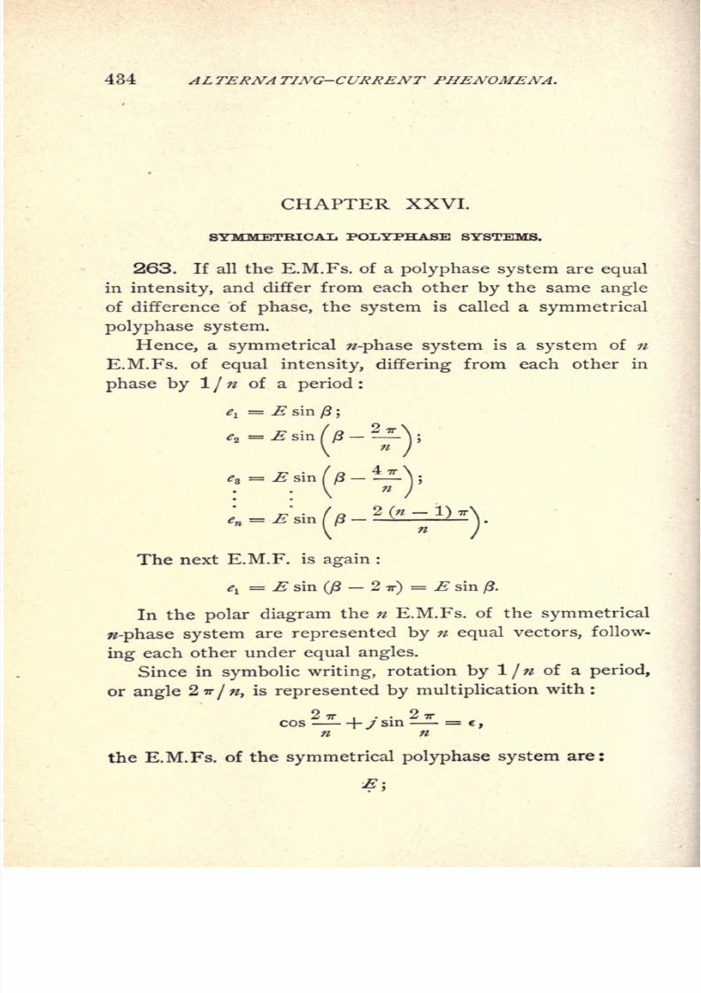
8/2/2019 Charles Steinmetz Theorycalculatio00steiiala
http://slidepdf.com/reader/full/charles-steinmetz-theorycalculatio00steiiala 460/557
434 ALTERNATING-CURRENT PHENOMENA.
CHAPTER XXVI.
SYMMETRICAL POLYPHASE SYSTEMS.
263. If all the E.M.Fs. of a polyphase system are equal
in intensity, and differ from each other by the same angle
of difference of phase, the system is called a symmetrical
polyphase system.
Hence, a symmetrical w-phase system is a system of n
E.M.Fs. of equal intensity, differing from each other in
phase by 1 / n of a period :
*i= E sin (3 ;
e2 =sm((3-^L\',
en = E sin ( ft - L V* ~ -
\
The next E.M.F. is again :
^ = E sin(ft
2TT)= E sin
ft.
In the polar diagram the n E.M.Fs. of the symmetrical
0-phase system are represented byn
equal vectors,follow-
ing each other under equal angles.
Since in symbolic writing, rotation by l/ of a period,
or angle 2ir/n, is represented by multiplication with :
the E.M.Fs. of the symmetrical polyphase system are:
8/2/2019 Charles Steinmetz Theorycalculatio00steiiala
http://slidepdf.com/reader/full/charles-steinmetz-theorycalculatio00steiiala 461/557
SYMMETRICAL POLYPHASE SYSTEMS. 435
/ 9 T- ? -rr
E(cos + / sin =
'
n
f 2 (n 1) TT .. . 2 ( 1)^
fcos -i-L--
\-j sm ^-^'
V
The next E.M.F. is again :
E(cos 2 -n- +j sin 2
TT)= . e" = ..
Hence, it is
27T .. 27T n
/?e = cos--
-f J sm- = V 1.
;z
Or in other words :
In a symmetrical -phase system any E.M.F. of the
system is expressed by :
e'-Ej
where : e = -y/1.
264. Substituting now for n different values, we get
the different symmetrical polyphase systems, represented by
*E\
, n/T 2 7T . . 2 7T
where, e = vl = cos--\-j sin .
n n
1.)= 1 e = 1 c'^
= .,
the ordinary single-phase system.
2.) = 2 e = - 1 J = and - .
Since ^ is the return of E, n = 2 gives again the
single-phase system.
3
-1-/V3
8/2/2019 Charles Steinmetz Theorycalculatio00steiiala
http://slidepdf.com/reader/full/charles-steinmetz-theorycalculatio00steiiala 462/557
436 ALTERNATING-CURRENT PHENOMENA.
The three E.M.Fs. of the three-phase system are :
-i-yV3
Consequently the three-phase system is the lowest sym-
metrical polyphase system.
4.) n = 4, c = cos +/ sin =/,2 =
1, e3 = -
/.4 4
The four E.M.Fs. of the four-phase system are:
* =, J, -E, -JE.
They are in pairs opposite to each other :
E and E jE and JE.
Hence can be produced by two coils in quadrature with
each other, analogous as the two-phase system, or ordinary
alternating-current system, can be produced by one coil.
Thus the symmetrical quarter-phase system is a four-
phase system.
Higher systems, than the quarter-phase or four-phase
system, have not been very extensively used, and are thus
of lesspractical
interest.
A symmetrical six-phase system,derived by transformation from a three-phase system, has
found application in synchronous converters, as offering a
higher output from these machines, and a symmetrical eight-
phase system proposed for the same purpose.
265. A characteristic feature of the symmetrical-
phase system is that under certain conditions it can pro-
duce a M.M.F. of constant intensity.
If equal magnetizing coils act upon a point under
equal angular displacements in space, and are excited by the
n E.M.Fs. of a symmetrical w-phase system, a M.M.F. of
constant intensity is produced at this point, whose direction
revolves synchronously with uniform velocity.
Let,
8/2/2019 Charles Steinmetz Theorycalculatio00steiiala
http://slidepdf.com/reader/full/charles-steinmetz-theorycalculatio00steiiala 463/557
SYMMETRICAL POLYPHASE SYSTEMS. 437
E= effective value of impressed E.M.F.
/ = effective value of current.
Hence,
& =n'f= effective M.M.F. of one of the magnetizing coils.
Then the instantaneous value of the M.M.F. of the coil
acting in the direction 2*'/
is :
The two rectangular space components of this M.M.F. are;
and
Hence the M.M.F. of this coil can be expressed by the
symbolic formula :
fin
\n
Thus the total or resultant M.M.F. of the n coils dis-
placed under the n equal angles is :
or, expanded :
n

8/2/2019 Charles Steinmetz Theorycalculatio00steiiala
http://slidepdf.com/reader/full/charles-steinmetz-theorycalculatio00steiiala 464/557
438 ALTERNATING-CURRENT PHENOMENA.
It is, however :
cos'2 + / sin cos =
(1 + cos +/ sin
]n n n V w w
/\ /
sin 2=1 cos ?Z+ysin2== ^Yl- cos i^'-ysin
4̂ 'z y
_ ^ /I _ ,2AX
2(1-^
and,since:
5t<2< =
0,
it is, /=nn' f^
(-sin ft
_ y cos ft),
or,
the symbolic expression of the M.M.F. produced by the
circuits of the symmetrical -phase system, when exciting
n equal magnetizing coils displaced in space under equal
angles.
The absolute value of this M.M.F. is :
nn' I n"S n<5
V2 V2 2
Hence constant and equal w/V2 times the effective
M.M.F. of each coil or /2 times the maximum M.M.F.
of each coil.
The phase of the resultant M.M.F. at the time repre-
sented by the angle ft is :
tan w = cot/8 ;
hence w =/? ^
That is, the M.M.F. produced by a symmetrical -phase
system revolves with constant intensity :

8/2/2019 Charles Steinmetz Theorycalculatio00steiiala
http://slidepdf.com/reader/full/charles-steinmetz-theorycalculatio00steiiala 465/557
SYMMETRICAL POLYPHASE SYSTEMS. 439
F=V2
5
and constant speed, in synchronism with the frequency of
the system ; and, if the reluctance of the magnetic circuit
is constant, the magnetism revolves with constant intensity
and constant speed also, at the point acted upon symmetri-
cally by the n M.M.Fs. of the w-phase system.
This is a characteristic feature of the
symmetrical poly-
phase system.
266. In the three-phase system, n = 3, F= 1.5<5max
where $max is the maximum M.M.F. of each of the magne-
tizing coils.
In a symmetrical quarter-phase system, n = 4, F = 2
^tnax , where $maje is the maximum M.M.F. of each of the
four magnetizing coils, or, if only two coils are used, since
the four-phase M.M.Fs. are opposite in phase by two, F =
&max> where ^max is the maximum M.M.F. of each of the
two magnetizing coils of the quarter-phase system.
While the quarter-phase system, consisting of two E.M.Fs.
displaced by one-quarter of a period, is by its nature an
unsymmetrical system, it shares a number of features
as, for instance, the ability of producing a constant result-
ant M.M.F. with the symmetrical system, and may be
considered as one-half of a symmetrical four-phase system.
Such systems, consisting of one-half of a symmetrical
system, are called hemisymmetrical systems.
8/2/2019 Charles Steinmetz Theorycalculatio00steiiala
http://slidepdf.com/reader/full/charles-steinmetz-theorycalculatio00steiiala 466/557
440 ALTERNATING-CURRENT PHENOMENA.
CHAPTER XXVII.
BALANCED AND UNBALANCED POLYPHASE SYSTEMS.
267. If an alternating E.M.F. :
e = E V2 sin(3,
produces a current :
* = 7V2sin (/? a),
where u> is the
angleof
lag,
the
poweris :
p = ei = 2 Ssin ft sin(ft S)
=S(cos
a cos (2 a)),
and the average value of power :
Substituting this,the instantaneous value of
poweris
found as :
Hence the power, or the flow of energy, in an ordinary
single-phase alternating-current circuit is fluctuating, and
varies with twice the frequency of E.M.F. and current,
unlike the power of a continuous-current circuit, which is
constant :
/-**
If the angle of lag= it is :
p = P (1 cos 2 0) ;
hence the flow of power varies between zero and 2Ptwhere
P is the average flow of energy or the effective power of
the circuit.

8/2/2019 Charles Steinmetz Theorycalculatio00steiiala
http://slidepdf.com/reader/full/charles-steinmetz-theorycalculatio00steiiala 467/557
BALANCED POLYPHASE SYSTEMS. 441
If the current lags or leads the E.M.F. by angle the
power varies between
andcos u>
that is, becomes negative for a certain part of each half-
wave. That is, for a time during each half-wave, energy
flows back into the generator, while during the other part
of the half-wave the generator sends out energy, and the
difference between both is the effective power of the circuit.
If = 90, it is :
O rt," p >
that is, the effective power : P = 0, and the energy flows
to and fro between generator and receiving circuit.
Under any circumstances, however, the flow of energy in
the single-phase system is fluctuating at least between zero
and a maximum value, frequently even reversing.
268. If in a polyphase system
*D ez> *s>= instantaneous values of E.M.F.
;
h) *2, t'a,= instantaneous values of current pro-
duced thereby ;
the total flow of power in the system is :
p = glt\ -f <?2/2 -j- e,j, -f . . . .
The average flow of power is :
P =i /i cos >! -(- E<i /2 cos w 2 -f- . . . .
The polyphase system is called a balanced system, if the
flow of energy :
/ = e\i\ + <V2 + W, +.'.'.;..
is constant, and it is called an unbalanced system if the
flow of energy varies periodically, as in the single-phase sys-
tem;and the ratio of the minimum value to the maximum
value of power is called the balance factor of the system.

8/2/2019 Charles Steinmetz Theorycalculatio00steiiala
http://slidepdf.com/reader/full/charles-steinmetz-theorycalculatio00steiiala 468/557
442 ALTERNATING-CURRENT PHENOMENA.
Hence in a single-phase system on non-inductive circuit,
that is, at no-phase displacement, the balance factor is zero ;
and it is negative in a single-phase system with lagging or
leading current, and becomes = 1, if the phase displace-
ment is 90 that is, the circuit is wattless.
269. Obviously, in a polyphase system the balance of
the system is a function of the distribution of load between
the different branch circuits.
A balanced system in particular is called a polyphase
system, whose flow of Energy is constant, if all the circuits
are loaded equally with a load of the same character, that
is, the same phase displacement.
270. All the symmetrical systems from the three-phase
system upward are balanced systems. Many unsymmetrical
systems are balanced systems also.
1.) Three-phase system :
Let
^ = E V2 sinft,
and t\= I V2 sin (ft w) ;
ez = E V2 sin (ft-
120), /2= / V2 sin (0
- -120) ;
ez= E V2 sin
(ft-
240), /3= /V2 sin (ft
- & - 240) ;
be the E.M.Fs. of a three-phase system, and the currents
produced thereby.
Then the total flow of power is :
/ = 2 .57(sin {3
sin (ft fi) + sin((3 120) sin
(ft& 120)
+ sin (ft 240) sin ($ <* 240))
= 3 .7cos w = T5
,or constant.
Hence the symmetrical three-phase system is a balanced
system.
2.) Quarter-phase system :
Letl= ^2s\nft, t\
= I \/2 sin (ft-
5) ;
e2 = E V2 cosft, 4 = 7V2 cos (ft
- ) ;

8/2/2019 Charles Steinmetz Theorycalculatio00steiiala
http://slidepdf.com/reader/full/charles-steinmetz-theorycalculatio00steiiala 469/557
BALANCED POLYPHASE SYSTEMS. 443
be the E.M.Fs. of the quarter-phase system, and the cur-
rents produced thereby.
This is an unsymmetrical" system, but the instantaneous
flow of power is :
/ = 2 I(sm J3sin (/? 5) + cos ft cos (0 >))
= 2 Scos w = P, or constant.
Hence the quarter-phase system is an unsymmetrical bal-
anced system.
3.)The symmetrical -phase system, with equal load
and equal phase displacement in all n branches, is a bal-
anced system. For, let :
e(= E V2 sin ( ft
- "\ = E.M.F.;
V /
/ 2 IT A*',-
= 7V2 sinO S = current
V Vthe instantaneous flow of power is :
l V 7 \
EI\ yr cos a -57-035^2 /?--
or p = n EI cos w = T7
,or constant.
271. An unbalanced polyphase system is the so-called
invertedthree-phase system,*
derived from two branches of
a three-phase system by transformation by means of two
transformers, whose secondaries are connected in opposite
direction with respect to their primaries. Such a system
takes an intermediate position between the Edison three-
wire system and the three-phase system. It shares with
the latter the polyphase feature, and with the Edison three-
* Also called "polyphase monocyclic system," since the E.M.F. triangle is similar to
that usual in the single-phase monocyclic system.
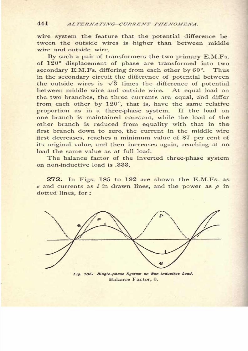
8/2/2019 Charles Steinmetz Theorycalculatio00steiiala
http://slidepdf.com/reader/full/charles-steinmetz-theorycalculatio00steiiala 470/557
444 ALTERNATING-CURRENT PHENOMENA.
wire system the feature that the potential difference be-
tween the outside wires is higher than between middlewire and outside wire.
By such a pair of transformers the two primary E.M.Fs.
of 120 displacement of phase are transformed into two
secondary E.M.Fs. differing from each other by 60. Thus
in the secondary circuit the difference of potential between
the outside wires is V3 times the difference of potential
between middle wire and outside wire. At equal load on
the two branches, the three currents are equal, and differ
from each other by 120, that is, have the same relative
proportion as in a three-phase system. If the load on
one branch is maintained constant, while the load of the
other branch is reduced from equality with that in the
first branch down to zero, the current in the middle wire
first decreases, reaches a minimum value of 87 per cent of
its original value, and then increases again, reaching at no
load the same value as at full load.
The balance factor of the inverted three-phase system
on non-inductive load is .333.
272. In Figs. 185 to 192 are shown the E.M.Fs. as
e and currents as i in drawn lines, and the power as / in
dotted lines, for :
Fig. 185. Single-phase System on Non-inductive Load.

8/2/2019 Charles Steinmetz Theorycalculatio00steiiala
http://slidepdf.com/reader/full/charles-steinmetz-theorycalculatio00steiiala 471/557
BALANCED POLYPHASE SYSTEMS. 445
Fig. 186. Single-phase System on Inductiue Load of 60 Lag.
Balance Factor,- .333.
Fig. 187. Quarter-phase System on Non-inductiui Load.
Balance Factor, + 1.
Fig. 183. Quarter-phase System on Inductiue Lozd of 60 Lag.

8/2/2019 Charles Steinmetz Theorycalculatio00steiiala
http://slidepdf.com/reader/full/charles-steinmetz-theorycalculatio00steiiala 472/557
446 ALTERNATING-CURRENT PHENOMENA.
Fig. 189. Three-phase System on Non-induct'we Load.
Balance Factor, + 1.
Fig. 190. Three-phase System on Inductive Load of 60 Lag.
Balance Factor, + 1.
191. Inverted Three-phase System
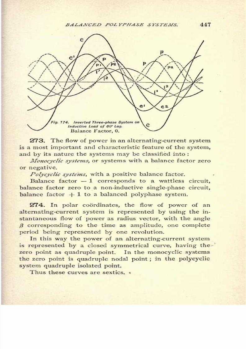
8/2/2019 Charles Steinmetz Theorycalculatio00steiiala
http://slidepdf.com/reader/full/charles-steinmetz-theorycalculatio00steiiala 473/557
BALANCED POLYPHASE SYSTEMS. 447
Fig. 174. Inverted Three-phase System on
Inductive Load of 60 Lag.
Balance Factor, 0.
273. The flow of power in an alternating-current system
is a most important and characteristic feature of the system,
and by its nature the systems may be classified into :
Monocyclic systems, or systems with a balance factor zero
or negative.
Polycyclic systems, with a positive balance factor.
Balance factor 1 corresponds to a wattless circuit,
balance factor zero to a non-inductive single-phase circuit,
balance factor + 1 to a balanced polyphase system.
274. In polar coordinates, the flow of power of an
alternating-current system is represented by using the in-
stantaneous flow of power as radius vector, with the angle
($ corresponding to the time as amplitude, one complete
period being represented by one revolution.
In this way the power of an alternating-current system
is represented by a closed symmetrical curve, having the
zero point as quadruple point. In the monocyclic systems
the zero point is quadruple nodal point ;in the polycyclic
system quadruple isolated point.
Thus these curves are sextics.
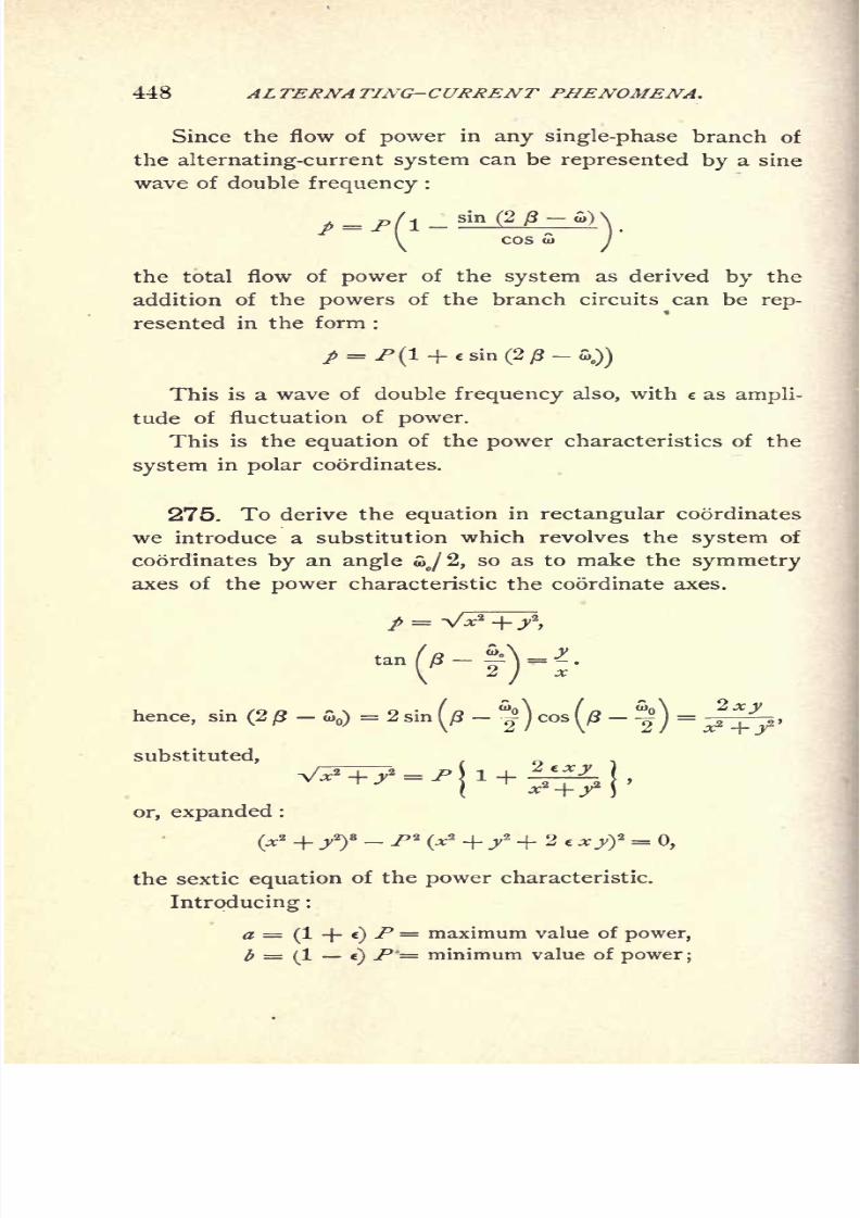
8/2/2019 Charles Steinmetz Theorycalculatio00steiiala
http://slidepdf.com/reader/full/charles-steinmetz-theorycalculatio00steiiala 474/557
448 ALTERNATING-CURRENT PHENOMENA.
Since the flow of power in any single-phase branch of
the alternating-current system can be represented by a sine
wave of double frequency :
the total flow of power of the system as derived by the
addition of the powers of the branch circuits can be rep-
resented in the form :
/ = />(! + sin (2-
a.))
This is a wave of double frequency also, with c as ampli-
tude of fluctuation of power.
This is the equation of the power characteristics of the
system in polar coordinates.
275. To derive the equation in rectangular coordinates
we introduce a substitution which revolves the system of
coordinates by an angle o>o/2, so as to make the symmetry
axes of the power characteristic the coordinate axes.
hence, sin (2 ft- S>
)= 2 sin^
-^ )
cos(/?
-^ j
=
substituted,
^M'+^j.
or, expanded :
P 2
(x2 + /* + 2 e A:^)
2 =0,
the sextic equation of the power characteristic.
Introducing :
a =(! + )/'=
maximum value of
power,b = (1 c)
P'= minimum value of power;

8/2/2019 Charles Steinmetz Theorycalculatio00steiiala
http://slidepdf.com/reader/full/charles-steinmetz-theorycalculatio00steiiala 475/557
BALANCED POLYPHASE SYSTEMS. 449
it is
**?>a + b
hence, substituted, and expanded :
(*+/) - \{a (x + j)2 + b (x -X>T> =
the equation of the power characteristic, with the main
power axes a and b, and the balance factor: bIa.
It is thus :
Single-phase non-inductive circuit : / = /> (1 + sin 2 <),
b = 0, a = 2P
Single-phase circuit, 60 lag : / = P (1 + 2 sin 2<),
i*.~+"
Single-phase circuit, 90 lag :/ = ^ /sin 2 <, b = E I,
a = + El2
/, &/a= -1.
Three-phase non-inductive circuit : p = P, ^ = 1, a =
x^+y* P 2 = 0: circle. &/a = + 1.
Three-phase circuit,60
lag:
/=
P,6 =
1,
a = 1
a? +/- 7>a = : circle. /= + !.
Quarter-phase non-inductive circuit :p = P,b = ]-)a =
x*
_|_ y _ ^2 = o .
circlei ^ /^ = _|_ i.
Quarter-phase circuit, 60 lag : p = P, b = 1, tf = 1
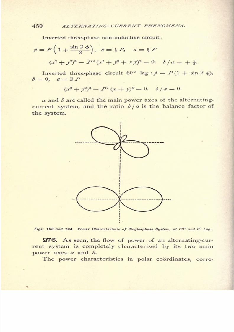
8/2/2019 Charles Steinmetz Theorycalculatio00steiiala
http://slidepdf.com/reader/full/charles-steinmetz-theorycalculatio00steiiala 476/557
450 ALTERNATING-CURRENT PHENOMENA.
Inverted three-phase non-inductive circuit :
Inverted three-phase circuit 60 lag :/ = f (1 -\- sin 2 <),
b = 0, a = 2 P
(y? + /)3_ />2
(x _|_ yy = 0<
fila = Q f
a and <5 are called the main power axes of the alternating-
current system, and the ratio b [a is the balance factor of
the system.
Figs. 193 and 104. Power Characteristic of Single-phase System, at 60 and Lag.
276. As seen, the flow of power of an alternating-cur-
rent system is completely characterized by its two main
power axes a and b.
The power characteristics in polar coordinates, corre-
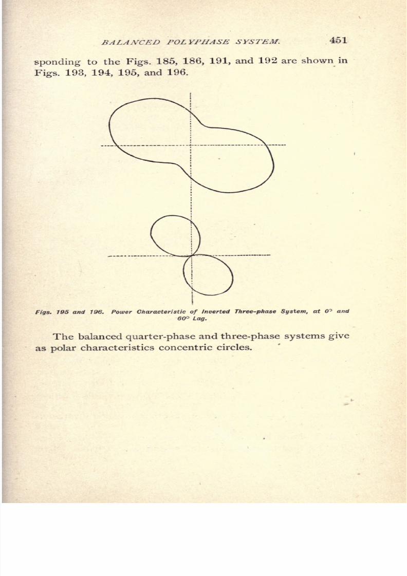
8/2/2019 Charles Steinmetz Theorycalculatio00steiiala
http://slidepdf.com/reader/full/charles-steinmetz-theorycalculatio00steiiala 477/557
BALANCED POLYPHASE SYSTEM. 451
spending to the Figs. 185, 186, 191, and 192 are shown in
Figs. 193, 194, 195, and 196.
Figs. 195 and 196. Power Characteristic of Inverted Three-phase System, at and
60 Lag.
The balanced quarter-phase and three-phase systems give
as polar characteristics concentric circles.

8/2/2019 Charles Steinmetz Theorycalculatio00steiiala
http://slidepdf.com/reader/full/charles-steinmetz-theorycalculatio00steiiala 478/557
452 ALTERNATING-CURRENT PHENOMENA.
CHAPTER XXVIII.
INTERLINKED POLYPHASE SYSTEMS.
277. In a polyphase system the different circuits of
displaced phases, which constitute the system, may either
be entirely separate and without electrical connection with
each other, or they may be connected with each other
electrically, so that a part of the electrical conductors are
in common to the different phases, and in this case the
system is called an interlinked polyphase system.
Thus, for instance, the quarter-phase system will be
called an independent system if the two E.M.Fs. in quadra-
ture with each other are produced by two entirely separate
coils of the same, or different but rigidly connected, arma-
tures, and are connected to four wires which energize inde-
pendent circuits in motors or other receiving devices. If
the quarter-phase systemis
derived by connecting four
equidistant points of a closed-circuit drum or ring-wound
armature to the four collector rings, the system is an inter-
linked quarter-phase system.
Similarly in a three-phase system. Since each of the
three currents which differ from each other by one-third
of a period is equal to the resultant of the other two cur-
rents, it can be considered as the return circuit of the other
two currents, and an interlinked three-phase system thus
consists of three wires conveying currents differing by one-
third of a period from each other, so that each of the three
currents is a common return of the other two, and inversely.
278. In an interlinked polyphase system two ways exist
of connecting apparatus into the system.

8/2/2019 Charles Steinmetz Theorycalculatio00steiiala
http://slidepdf.com/reader/full/charles-steinmetz-theorycalculatio00steiiala 479/557
INTERLINKED POLYPHASE SYSTEMS. 453
1st. The star connection, represented diagrammatically
in Fig. 197. In this connection the n circuits excited by
currents differing from each other by 1 / n of a period, are
connected with their one end together into a neutral point
or common connection, which may either be grounded or
connected with other corresponding neutral points, or insu-
lated.
In a three-phase system this connection is usually called
a Y connection, from a similarity of its diagrammatical rep-
resentation with the letter Y, as shown in Fig. 181.
2d. The ring connection, represented diagrammatically
in Fig. 198, where the n circuits of the apparatus are con-
nected with each other in closed circuit, and the corners
or points of connection of adjacent circuits connected to
the n lines of the polyphase system. In a three-phase
system this connection is called the delta connection, from
the similarity of its diagrammatic representation with the
Greek letter Delta, as shown in Fig. 182.
In consequence hereof we distinguish between star-
connected and ring-connected generators, motors, etc., or
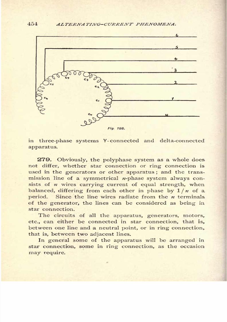
8/2/2019 Charles Steinmetz Theorycalculatio00steiiala
http://slidepdf.com/reader/full/charles-steinmetz-theorycalculatio00steiiala 480/557
454 ALTERNATING-CURRENT PHENOMENA.
Fig. 198.
in three-phase systems Y- connected and delta-connected
apparatus.
279. Obviously, the polyphase system as a whole does
not differ, whether star connection or ring connection is
used in the generators or other apparatus ;and the trans-
mission line of a symmetrical -phase system always con-
sists of n wires carrying current of equal strength, when
balanced, differing from each other in phase by l/ of a
period. Since the line wires radiate from the n terminals
of the generator, the lines can be considered as being in
star connection.
The circuits of all the apparatus, generators, motors,
etc., can either be connected in star connection, that is,
between one line and a neutral point, or in ring connection,
that is, between two adjacent lines.
In general some of the apparatus will be arranged in
star
connection,some in
ring connection,as the occasion
may require.
8/2/2019 Charles Steinmetz Theorycalculatio00steiiala
http://slidepdf.com/reader/full/charles-steinmetz-theorycalculatio00steiiala 481/557
INTERLINKED POLYPHASE SYSTEMS. 455
280. In the same way as we speak of star connection
and ring connection of the circuits of the apparatus, the
term star potential and ring potential, star current and ring
current, etc., are used, whereby as star potential or in a
three-phase circuit Y potential, the potential difference be-
tween one of the lines and the neutral point, that is, a point
having the same difference of potential against all the lines,
is understood;that is, the potential as measured by a volt-
meter connected into star or Y connection. By ring or
delta potential is understood the difference of potential
between adjacent lines, as measured by a voltmeter con-
nected between adjacent lines, in -ring or delta connec-
tion.
In the same way the star or Y current is the current
flowing from one line to a neutral point;
the ring or delta
current, the current flowing from one line to the other.
The current in the transmission line is always the star
or Y current, and the potential difference between the line
wires, the ring or delta potential.
Since the star potential and the ring potential differ
from each other, apparatus requiring different voltages can
be connected into the same polyphase mains, by using either
star or ring connection.
281. If in a generator with star-connected circuits, the
E.M.F. per circuit = E, and the common connection or
neutral point is denoted by zero, the potentials of the n
terminals are :
or in general : t* JS,
at the z'th
terminal, where :
* = 0, 1, 2 ....- 1, e = cos +j sin = -\/l.
8/2/2019 Charles Steinmetz Theorycalculatio00steiiala
http://slidepdf.com/reader/full/charles-steinmetz-theorycalculatio00steiiala 482/557
456 ALTERNATING-CURRENT PHENOMENA.
Hence the E.M.F. in the circuit from the zth
to the *
terminal is :
Eki= **E ^E =
(c* e') E.
The E.M.F. between adjacent terminals i and i + 1 is :
(e.+i -J)E = e*
(e-
1) E.
In a generator with ring-connected circuits, the E.M.F.
per circuit :
c
l
Eis the ring E.M.F., and takes the place of
while the E.M.F. between terminal and neutral point, or
the star E.M.F., is :
Hence in a star-connected generator with the E.M.F.
E per circuit, it is :
Star E.M.F., IE.
RingE-M.F., c'Xc-1)^.E.M.F. between terminal / and terminal k, (c* e')
E.
In a ring-connected generator with the E.M.F. E per
circuit, it is :
Star E.M.F.,^ E.
e 1'
Ring E.M.F., C E.
E.M.F. between terminals * and k,
e ~ e*
E.1
'
In a star-connected apparatus, the E.M.F. and the cur-
rent per circuit have to be the star E.M.F. and the star
current. In a ring-connected apparatus the E.M.F. and
current per circuit have to be the ring E.M.F. and ring
current.
In the generator of a symmetrical polyphase system, if :
c'' E are the E.M.Fs. between the n terminals and the
neutral point, or star E.M.Fs.,
8/2/2019 Charles Steinmetz Theorycalculatio00steiiala
http://slidepdf.com/reader/full/charles-steinmetz-theorycalculatio00steiiala 483/557
INTERLINKED POLYPHASE SYSTEMS. 457
If= the currents issuing from terminal i over a line of
the impedance Z{ (including generator impedance in star
connection), we have :
Potential at end of line i :
Difference of potential between terminals k and i :
where/,.
is the star current of the system, Ztthe star im-
pedance.
The ring potential at the end of the line between ter-
minals i and k is Eik ,
and it is :
Eile= Eti .
If now Iik denotes the current passing from terminal i to
terminal k, and Zik impedance of the circuit between ter-
minal i and terminal k, where :
fit= ~
/*,,
Zt* = Zti ,
it is Eik= Zit Iik .
If Iio denotes the current passing from terminal i to a
ground or neutral point, and Zio
is the impedance of this
circuit between terminal i and neutral point, it is :
Eio= *-
ZiSi = Zio lio .
282. We have thus, by Ohm's law and Kirchhoff's law :
If *' E is the E.M.F. per circuit of the generator, be-
tween the terminal i and the neutral point of the generator,
or the star E.M.F.
/,-= the current issuing from the terminal i of the gen-
erator, or the star current.
Zt= the impedance of the line connected to a terminal
i of the generator, including generator impedance.
EL= the E.M.F. at the end of line connected to a ter-
minal i of the generator.
8/2/2019 Charles Steinmetz Theorycalculatio00steiiala
http://slidepdf.com/reader/full/charles-steinmetz-theorycalculatio00steiiala 484/557
458 ALTERNATING-CURRENT PHENOMENA.
Eik= the difference of potential between the ends of
the lines i and k.
Iik= the current passing from line i to line k.
Zik= the impedance of the circuit between lines i and k.
Iio ,
Iioo
. . . .= the current passing from line i to neu-
tral points 0, 00, ....
Zio ,Z
ioo. . . .
= the impedance of the circuits between
line i and neutral points 0, 00, ....
It is then :
Zio= Zoi ,
etc.
2.)E
t=JE-Z
iI
i.
3.) Ei = Zi fi= Zioo fj 00
= . . . .
4.) Eik= Et
'- E{=
(t*-
e')E -
(Zklk-
ZJ^).
5.) Eik
= Zik Iik .
7.) If the neutral point of the generator does not exist,
as in ring connection, or is insulated from the other neutral
points :
IE/,, =0;
n
5E/ioo=
0, etc.
1
Where 0, 00, etc., are the different neutral points which
are insulated from each other.
If the neutral point of the generator and all the other
neutral points are grounded or connected with each other,
it is:

8/2/2019 Charles Steinmetz Theorycalculatio00steiiala
http://slidepdf.com/reader/full/charles-steinmetz-theorycalculatio00steiiala 485/557
INTERLINKED POLYPHASE SYSTEMS. 459
If the neutral point of the generator and all other neu-
tral points are grounded, the system is called a grounded
system. If the neutral points are not grounded, the sys-
tem is an insulated polyphase system, and an insulated
polyphase system with equalizing return, if all the neutral
points are connected with each other.
8.)The power of the polyphase system is
P = ^f e1
'
E Ii cos $i at the generator1
f ="^i ^* Eik Iik cos <f>it
in the receiving circuits.
8/2/2019 Charles Steinmetz Theorycalculatio00steiiala
http://slidepdf.com/reader/full/charles-steinmetz-theorycalculatio00steiiala 486/557
4GO ALTERNATING-CURRENT PHENOMENA.
CHAPTER XXIX.
TRANSFORMATION OF POLYPHASE SYSTEMS.
283. In transforming a polyphase system into another
polyphase system, it is obvious that the primary system
must have the same flow of power as the secondary system,
neglecting losses in transformation, and that consequently
a balanced system will be transformed again in a balanced
system, and an unbalanced system into an unbalanced sys-
tem of the same balance factor, since the transformer is an
apparatus not able to store energy, and thereby to change
the nature of the flow of power. The energy stored as
magnetism, amounts in a well-designed transformer only to
a very small percentage of the total energy. This shows
the futilityof producing symmetrical balanced polyphase
systems by transformation from the unbalanced single-phase
system without additional apparatus able to store energy
efficiently, as revolving machinery.
Since any E.M.F. can be resolved into, or produced by,
two components of given directions, the E.M.Fs. of any
polyphase system can be resolved into components or pro-
duced from components of two given directions. This en-
ables the transformation of any polyphase system into any
other polyphase system of the same balance factor by two
transformers only.
284. Let EltE
2 ,E
z. . . . be the E.M.Fs. of the
primary system which shall be transformed into
E{, 2', s
'
. . . . the E.M.Fs. of the secondary
system.
Choosing two magnetic fluxes, < and <, of different

8/2/2019 Charles Steinmetz Theorycalculatio00steiiala
http://slidepdf.com/reader/full/charles-steinmetz-theorycalculatio00steiiala 487/557
TRANSFORMATION OF POLYPHASE SYSTEMS, 461
phases, as magnetic circuits of the two transformers, which
induce the E.M.Fs., e and ?,
perturn,
bythe law of
paral-
lelogram the E.M.Fs., Elf E^, . . . . can be dissolved into
two components, Eland E
lt E^ and Ez ,
.... of the phases*
"e and J.
Then, -
E!, 2 ,' are the counter E.M.Fs. which have to be-
induced in the primary circuits of the first transformer;.
Ev E2 ,.... the counter E.M.F.'s which have to be in-
duced in the primary circuits of the second transformer..
hence
EI 1 7, 2 1 J . . . . are the numbers of turns of the primary
coils of the first transformer.
Analogously
EI /T 2 IT . . . . are the number of turns of the primary coils
in the second transformer.
In the same manner as the E.M.Fs. of the primary
system have been resolved into components in phase with
J and FJ the E.M.Fs. of the secondary system, E-^> E^, ....
are produced from components, E-f and E^, E and EJ,
.... in phase with ~e and J, and give as numbers of second
ary turns,
i
l
/ J, 2l
/? in the first transformer;
EI 1 7, EZ / F, .... in the second transformer.
That means each of the two transformers m and m con-
tains in general primary turns of each of the primary
phases, and secondary turns of each of the secondary
phases. Loading now the secondary polyphase system in
any desired manner, corresponding to the secondary cur-
rents, primary currents will flow in such a manner that the
total flow of power in the primary polyphase system is the
8/2/2019 Charles Steinmetz Theorycalculatio00steiiala
http://slidepdf.com/reader/full/charles-steinmetz-theorycalculatio00steiiala 488/557
4j^ ALTERNATING-CURRENT PHENOMENA.
same as the total flow of power in the secondary system,
plus the loss of power in the transformers.
285. As an instance may be considered the transforma-
tion of the symmetrical balanced three-phase system
E sinft,
E sin(ft 120), E sin
(ft 240),
in an unsymmetrical balanced quarter-phase system :
E' sinft,
E' sin (ft 90).
Let the magnetic flux of the two transformers be
(/>cos and
</>cos
(ft 90).
Then the E.M.Fs. induced per turn in the transformers
e sinft
and e sin(ft 90) ;
hence, in the primary circuit the first phase, E sin ft, will
give, in the first transformer, E/e primary turns; in the
second transformer, primary turns.
The second phase, E sin(ft 120), will give, in the
first transformer, E/2 e primary turns; in the second
E x ~\/3
transformer, primary turns.2 e
The third phase, E sin (ft 240), will give, in the first
transformer, E/le primary turns; in the second trans-
former, primary turns.2 e
In the secondary circuit the first phase E' sin ft will give
in the first transformer: E'/e secondary turns; in the
second transformer : secondary turns.
The second phase : E' sin(ft 90) will give in the first
transformer : secondary turns;in the second transformer,
E'Ie secondary turns.
Or, if :
E = 5,000 E' = 100, e = 10.
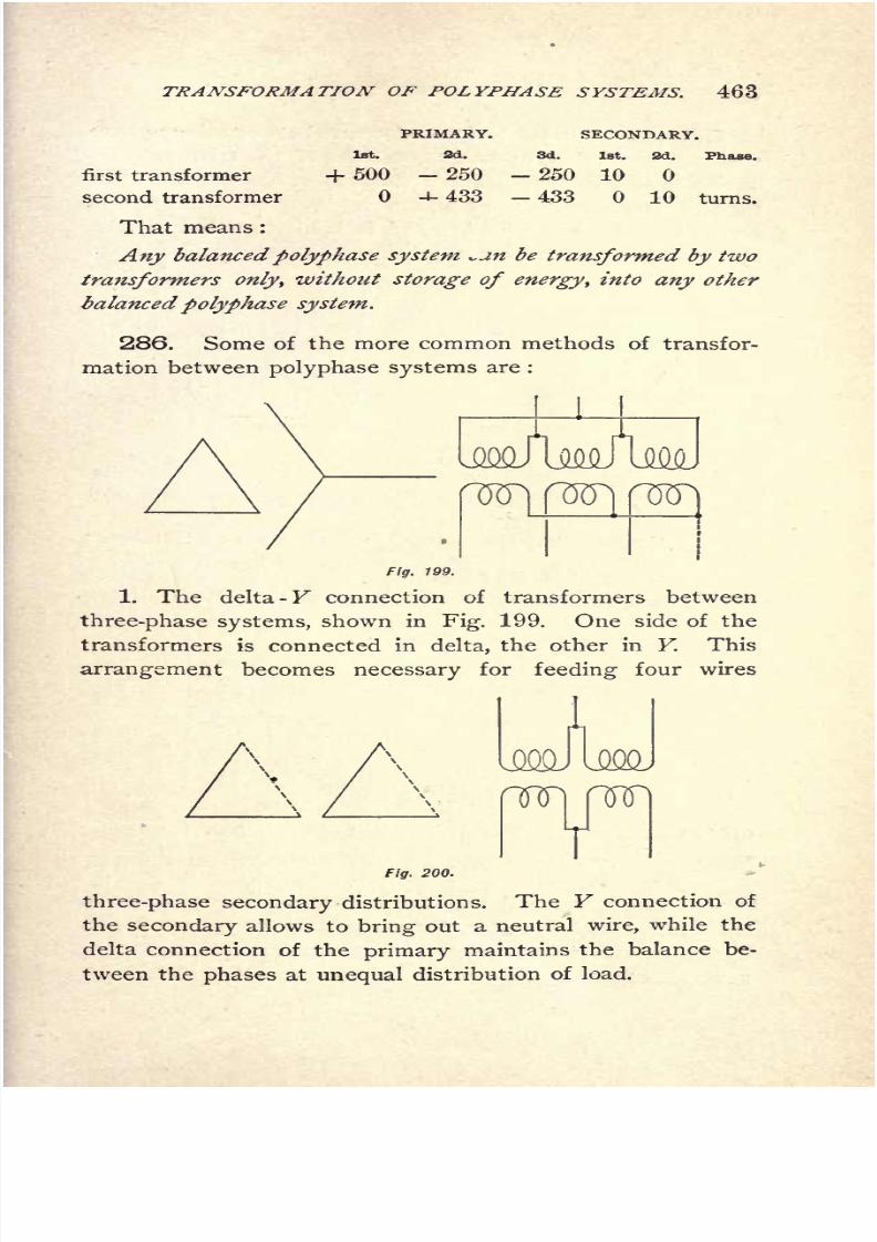
8/2/2019 Charles Steinmetz Theorycalculatio00steiiala
http://slidepdf.com/reader/full/charles-steinmetz-theorycalculatio00steiiala 489/557
TRANSFORMATION OF POLYPHASE SYSTEMS. 463
PRIMARY.
1st. 2d.
SECONDARY.
3d.1st. 2d. Phase.
first transformer
second transformer
+ 500 - 250 - 250
4- 433 - 433
10
10 turns.
That means :
Any balancedpolyphase system *.jm be transformed by two
transformers only, without storage of energy, into any other
balancedpolyphase system.
286. Some of the more common methods of transfor-
mation between polyphase systems are :
Fig. 799.
1. The delta -Y connection of transformers between
three-phase systems, shown in Fig. 199. One side of the
transformers is connected in delta, the other in Y. This
arrangement becomes necessary for feeding four wires
rwi nnr
VFig. 200.
three-phase secondary distributions. The Y connection of
the secondary allows to bring out a neutral wire, while the
delta connection of the
primary
maintains the balance be-
tween the phases at unequal distribution of load.

8/2/2019 Charles Steinmetz Theorycalculatio00steiiala
http://slidepdf.com/reader/full/charles-steinmetz-theorycalculatio00steiiala 490/557
464 ALTERNA TING-CURRENT PHENOMENA.
2. The L connection of transformers between three-phase
systems, consisting in using two sides of the triangle only,
as shown in Fig. 200. This arrangement has the disadvan-
tage of transforming one phase by two transformers in
series, hence is less efficient, and is liable to unbalance the
system by the internal impedance of the transformers.
Fig. 201.
3. The main and teaser, or T connection of trans-
formers between three-phase systems, as shown in Fig. 201.
V3One of the two transformers is wound for ~-~- times the
voltage of the other (the altitude of the equilateral triangle),
and connected with one of its ends to the center of the
Fig. 202.
other transformer. From the point inside of the teaser
transformer, a neutral wire can be brought out in this con-
nection.
4. The monocyclic connection, transforming between
three-phase and inverted three-phase or polyphase mono-
cycle, bytwo
transformers,the
secondaryof one
beingreversed regarding its primary, as shown in Fig. 202.
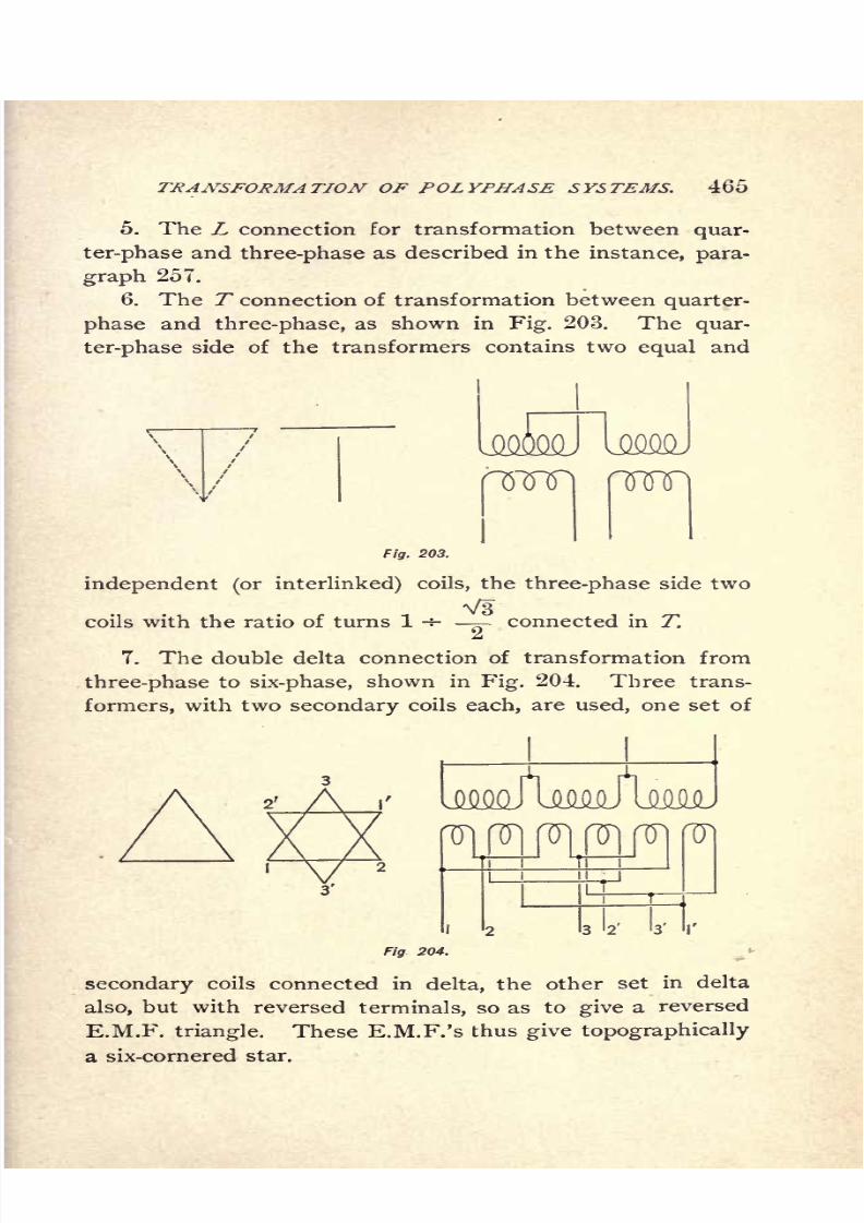
8/2/2019 Charles Steinmetz Theorycalculatio00steiiala
http://slidepdf.com/reader/full/charles-steinmetz-theorycalculatio00steiiala 491/557
TRANSFORMATION OF POLYPHASE SYSTEMS. 465
5. The L connection for transformation between quar-
ter-phase and three-phase as described in the instance, para-
graph 257.
6. The T connection of transformation between quarter-
phase and three-phase, as shown in Fig. 203. The quar-
ter-phase side of the transformers contains two equal and
Fig. 203.
independent (or interlinked) coils, the three-phase side two
Vscoils with the ratio of turns 1 -=- ^ connected in T.
7. The double delta connection of transformation from
three-phase to six-phase, shown in Fig. 204. Three trans-
formers, with two secondary coils each, are used, one set of
Fig 204.
secondary coils connected in delta, the other set in delta
also, but with reversed terminals, so as to give a reversed
E.M.F. triangle. These E.M.F.'s thus give topographically
a six-cornered star.

8/2/2019 Charles Steinmetz Theorycalculatio00steiiala
http://slidepdf.com/reader/full/charles-steinmetz-theorycalculatio00steiiala 492/557
466 ALTERNA TING-CURRENT PHENOMENA.
8. The double Y connection of transformation from
three-phase to six-phase, shown in Fig. 205. It is analo-
gous to(7),
the delta connection merely being replaced by
the Y connection. The neutrals of the two F's may be
connected together and to an external neutral if desired.
9. The double T connection of transformation from
Fig. 205.
three-phase to six-phase, shown in Fig. 206. Two trans-
formers are used with two secondary coils which are T con-
nected, but one with reversed terminals. This method
allows a secondary neutral also to be brought out.
287. Transformation with achange
of the balance
factor of the system is possible only by means of apparatus
Fig. 208.
able to store energy, since the difference of power between
primary and secondary circuit has to be stored at the time
when the secondary power is below the primary, and re-
turned the time when the is below

8/2/2019 Charles Steinmetz Theorycalculatio00steiiala
http://slidepdf.com/reader/full/charles-steinmetz-theorycalculatio00steiiala 493/557
TRANSPORMATION OF POLYPHASE SYSTEMS. 467
the secondary. The most efficient storing device of electric
energy is mechanical momentum in revolving machinery.
It has, however, the disadvantage of requiring attendance;
fairly efficient also are capacities and inductances, but, as a
rule, have the disadvantage not to give constant potential.
8/2/2019 Charles Steinmetz Theorycalculatio00steiiala
http://slidepdf.com/reader/full/charles-steinmetz-theorycalculatio00steiiala 494/557
468 ALTERNATING-CURRENT PHENOMENA.
CHAPTER XXX.
EFFICIENCY OF SYSTEMS.
288. In electric power transmission and distribution,
wherever the place of consumption of the electric energy
is distant from the place of production, the conductors
which transfer the current are a sufficiently large item to
require consideration, when deciding which system and
what potential is to be used.
Ingeneral,
intransmitting
agiven amount
of
powerat a
given loss over a given distance, other things being equal,
the amount of copper required in the conductors is inversely
proportional to the square of the potential used. Since
the total power transmitted is proportional to the product
of current and E.M.F., at a given power, the current will
vary inversely proportional to the E.M.F., and therefore,
since the loss is proportional to the product of current-
square and resistance, to give the same loss the resistance
must vary inversely proportional to the square of the cur-
rent, that is, proportional to the square of the E.M.F.;and
since the amount of copper is inversely proportional to the
resistance, other things being equal, the amount of copper
varies inversely proportional to the square of the E.M.F.
used.
This holds for any system.
Therefore to compare the different systems, as two-wire
single-phase, single-phase three-wire, three-phase and quar-
ter-phase, equality of the potential must be assumed.
Some systems, however, as for instance, the Edison
three-wiresystem,
or the invertedthree-phase system,
have
8/2/2019 Charles Steinmetz Theorycalculatio00steiiala
http://slidepdf.com/reader/full/charles-steinmetz-theorycalculatio00steiiala 495/557
EFFICIENCY OF SYSTEMS. 409
different potentials in the different circuits constituting the
system, and thus the comparison can be made either
1st. On the basis of equality of the maximum potential
difference in the system ;or
2d. On the basis of the minimum potential difference
in the system, or the potential difference per circuit or
phase of the system.
In low potential circuits, as secondary networks, where
the potential is not limited by the insulation strain, but by
the potential of the apparatus connected into the system,
as incandescent lamps, the proper basis of comparison is
equality of the potential per branch of the system, or per
phase.
On the other hand, in long distance transmissions where
the potentialis
notrestricted
by any consideration of ap-
paratus suitable for a certain maximum potential only, but
where the limitation of potential depends upon the problem
of insulating the conductors against disruptive discharge,
the proper comparison is on the basis of equality of the
maximum difference of potential in the system ;that is,
equal maximum dielectric strain on the insulation.
The same consideration holds in moderate potential
power circuits, in considering the danger to life from live
wires entering human habitations.
Thus the comparison of different systems of long-dis-
tance transmission at high potential or power distribution
for motors is to be made on the basis of equality of the
maximum difference of potential existing in the system.
The comparison of low potential distribution circuits for
lighting on the basis of equality of the minimum difference
of potential between any pair of wires connected to the
receiving apparatus.
289. 1st. Comparison on the basis of equality of the
minimum differenceof potential,
in low potential lighting
circuits :

8/2/2019 Charles Steinmetz Theorycalculatio00steiiala
http://slidepdf.com/reader/full/charles-steinmetz-theorycalculatio00steiiala 496/557
4TO ALTERNATING-CURRENT PHENOMENA.
In the single-phase alternating-current circuit, if e
E.M.F., i = current, r resistance per line, the total poweris = ei, the loss of power 2z'V.
Using, however, a three-wire system, the potential be-
tween outside wires and neutral being given =e, the
potential between the outside wires is == 2 e, that is, the dis-
tribution takes place at twice the potential, or only-' the
copper is needed to transmit the same power at the same
loss, if, as it is theoretically possible, the neutral wire has
no cross-section. If therefore the neutral wire is made of
the same cross-section with each of the outside wires, | of
the copper of the two-wire system is needed;
if the neutral
wire is the cross-section of each of the outside wires, T% of
the copper is needed. Obviously, a single-phase five-wire
system
will be a
system
of distribution at thepotential
4 e,
and therefore require only TV f the copper of the single-
phase system in the outside wires;and if each of the three
neutral wires is of i the cross-section of the outside wires,
/? = 10.93 per cent of the copper.
Coming now to the three-phase system with the poten-
tial e between the lines as delta potential, if i = the current
per line or Y current, the current from line to line or delta
current = ^ /VB
;and since three branches are used, the
total power is 3 ei\ /
V3 == e z'xV3. Hence if the same
power has to be transmitted by the three-phase system as
with the single-phase system, the three-phase line current
must be z'i= i / V3 where i single-phase current, r =
single-phase resistance per line, at equal power and loss;
hence if 1\ = resistance of each of the three wires, the loss
per wire is i? rt = izrt /.3, and the total loss is z
2
1\, while in
the single-phase system it is 2 t*r. Hence, to get the same
loss, it must be : rv = 2 r, that is, each of the three three-
phase lines has twice the resistance that is, half the cop-
per of each of the two single-phase lines;or in other words,
the three-phase system requires three-fourths of the copper
of the single-phase system of the same potential.
8/2/2019 Charles Steinmetz Theorycalculatio00steiiala
http://slidepdf.com/reader/full/charles-steinmetz-theorycalculatio00steiiala 497/557
EFFICIENCY OF SYSTEMS. 471
Introducing, however, a fourth or neutral wire into the
three-phase system, and connecting the lamps between the
neutral wire and the three outside wires that is, in Y con-
nection the potential between the outside wires or delta
potential will be = e X V3, since the Y potential = e, and
the potential of the system is raised thereby from e to
e V3;that is, only J as much copper is required in the out-
side wires as before that is \ as much copper as in the
single-phase two-wire system. Making the neutral of the
same cross-section as the outside wires, requires \ more
copper, or \ = 33.3 per cent of the copper of the single-
phase system ; making the neutral of half cross-section,
requires \ more, or ^ = 29.17 per cent of the copper of
the single-phase system. The system, however, now is a
four-wiresystem.
The independent quarter-phase system with four wires
is identical in efficiency to the two-wire single-phase sys-
tem, since it is nothing but two independent single-phase
systems in quadrature.
The four-wire quarter-phase system can be used as two
independent Edison three-wire systems also, deriving there-
from the same saving by doubling the potential betweenthe outside wires, and has in this case the advantage, that
by interlinkage, the same neutral wire can be used for both
phases, and thus one of the neutral wires saved.
In this case the quarter-phase system with common neu-
tral of full cross-section requires -fo= 31.25 per cent, the
quarter-phase system with common neutral of one-half cross-
section requires ^ = 28.125 per cent, of the copper of the
two-wire single-phase system.
In this case, however, the system is a five-wire system,
and as such far inferior to the five-wire single-phase system.
Coming now to the quarter-phase system with common
return and potential e per branch, denoting the current in
the outside wires
by
z'2 ,
the current in the central wire is
*aV2
;and if the same current density is chosen for all
8/2/2019 Charles Steinmetz Theorycalculatio00steiiala
http://slidepdf.com/reader/full/charles-steinmetz-theorycalculatio00steiiala 498/557
472 ALTERNATING-CURRENT PHENOMENA.
three wires, as the condition of maximum efficiency, and
the resistance of each outside wire denoted by rz , the re-
sistance of the central wire = r2 /V2, and the loss of power
per outside wire is z'
2
2 r2 ,
in the central wire 2 z'2
2 r2 /V2
= z'
2
2 r2V2
;hence the total loss of power is 2 z'
2
2 r2 + z'
22 r
2
V2 = z'
2
2 r2 (2 -f V2). The power transmitted per branch
is z'2 ^, hence the total power 2 z'
2e. To transmit the same
power as by a single-phase system of power, e z, it must
be z2=
z'/2; hence the loss,
* 2; a(2 +^ . Since this
loss shall be the same as the loss 2z' 2 r in the single-
phase system, it must be 2 r = - r2 ,
or r2 = ~. .
2 -}- V2
4- V^Therefore each of the outside wires must be times
o
as large as each single-phase wire, the central wire V2
times larger ;hence the copper required for the quarter-
phase system with common return bears to the copper
required for the single-phase system the relation :
2 (2 + V2) (2 + V5) V2 . 9 3 + 2V2^~ ~T~ ~T~~
per cent of the copper of the single-phase system.
Hence the quarter-phase system with common return
saves 2 per cent more copper than the three-phase system,
but is inferior to the single-phase three-wire system.
The inverted three-phase system, consisting of two
E.M.Fs. e at 60 displacement, and three equal currents
/8
in the three lines of equal resistance r3 , gives the out-
put 2^z'3 ,
that is, compared with the single-phase system,
/8=
z'/2.The loss in the three lines is 3 z'
3
2 r3=
| z2 r
s.
Hence, to give the same loss 2 z'2 r as the single-phase sys-
tem, it must be rs= f r, that is, each of the three wires
must have f of the copper cross-section of the wire in the
two-wire single-phase system ;or in other words, the in-
verted three-phasesystem
requires
^of the copper of the
two-wire single-phase system.

8/2/2019 Charles Steinmetz Theorycalculatio00steiiala
http://slidepdf.com/reader/full/charles-steinmetz-theorycalculatio00steiiala 499/557
EFFICIENCY OF SYSTEMS. 473
We get thus the result,
If a given power has to be transmitted at a given loss,
and a given minimum potential, as for instance 110 volts
for lighting, the amount of copper necessary is :
2 WIRES : Single-phase system, 100.0
3 WIRES : Edison three-wire single-phase sys-
tem, neutral full section, 37.5
Edison three-wire single-phase sys-
tem, neutral half-section, 31.25
Inverted three-phase system, 56.25
Quarter-phase system with common
return, 72.9
Three-phase system, 75.0
4 WIRES : Three-phase, with neutral wire full
section, 33.3
Three-phase, with neutral wire half-
section, 29.17
Independent quarter-phase system, 100.0
5 WIRES : Edison five-wire, single-phase system,
full neutral, 15.625
Edison five-wire, single-phase system,
half-neutral, 10.93
Four-wire, quarter-phase, with com-
mon neutral full section, 31.25
Four-wire, quarter-phase, with com-
mon neutral half-section, 28.125
We see herefrom, that in distribution for lighting that
is, with the same minimum potential, and with the samenumber of wires the single-phase system is superior to
any polyphase system.
The continuous-current system is equivalent in this'
comparison to the single-phase alternating-current system
of the same effective potential, since the comparison is
made on the basis of effective potential, and the power
depends upon the effective potential also.
8/2/2019 Charles Steinmetz Theorycalculatio00steiiala
http://slidepdf.com/reader/full/charles-steinmetz-theorycalculatio00steiiala 500/557
474 AL TERNA TING-CURRENT PHENOMENA.
290. Comparison on the Basis of Equality of the Maximum
Difference of Potential in the System, in Long-Distance
Transmission, Power Distribution, etc.
Wherever the potential is so high as to bring the ques-
tion of the strain on the insulation into consideration, or in
other cases, to approach the danger limit to life, the proper
comparison of different systems is on the basis of equality
of maximum potential in the system.
Hence in this case, since the maximum potential is
fixed, nothing is gained by three- or five-wire Edison sys-
tems. Thus, such systems do not come into consideration.
The comparison of the three-phase system with the
single-phase system remains the same, since the three-
phase system has the same maximum as minimum poten-
tial;that is :
The three-phase system requires three-fourths of the
copper of the single-phase system to transmit the same
power at the same loss over the same distance.
The four-wire quarter-phase system requires the same
amount of copper as the single-phase system, since it con-
sists of twosingle-phase systems.
In a quarter-phase system with common return, the
potential between the outside wire is V2 times the poten-
tial per branch, hence to get the same maximum strain on
the insulation that is, the same potential e between the
outside wires as -in the single-phase system the potential
per branch will be ej V2, hence the current z'4=
t/ V2, if i
equals the current of the single-phase system of equal
power, andt\V2 = i will be the current in the central
wire.
Hence, if r = resistance per outside wire, r/V2 =
resistance of central wire, and the total loss in the sys-
tem is :
, (2 + V2) =

8/2/2019 Charles Steinmetz Theorycalculatio00steiiala
http://slidepdf.com/reader/full/charles-steinmetz-theorycalculatio00steiiala 501/557
EFFICIENCY OF SYSTEMS. 475
Since in the single-phase system, the loss = 2 i2
r, it is :
2 + ~v/
2That is, each of the outside wires has to contain --
4
times as much copper as each of the single-phase wires.
2 x V2 /-The central wires have to contain-- V2 times as
^ (^ -4- ~v/2^much copper ;
hence the total system contains
2 +V2T- V2 times as much copper as each of the single-
3 + 2 ~\/2
phase wires;
that is,- times the copper of the
4
single-phase system.
Or,in other
words,A quarter-phase system with common return requires
3 + 2 A/2== 1.457 times as much copper as a single-phase
system of the same maximum potential, same power, and
same loss.
Since the comparison is made on the basis of equal
maximum potential, and the maximum potential of alter-
nating system is A/2 times that of a continuous-current
circuit of equal effective potential, the alternating circuit
of effective potential e compares with the continuous-cur-
rent circuit of potential e A/2, which latter requires only
half the copper of the alternating system.
This comparison of the alternating with the continuous-
current system is not proper however, since the continuous-
current potential introduces, besides the electrostatic strain,
an electrolytic strain on the dielectric which does not exist
in the alternating system, and thus makes the action of the
continuous-current potential on the insulation more severe
than that of an equal alternating potential. Besides, self-
induction having no effect on a steady current, continuous
current circuits as a rule have a self-induction far in excess

8/2/2019 Charles Steinmetz Theorycalculatio00steiiala
http://slidepdf.com/reader/full/charles-steinmetz-theorycalculatio00steiiala 502/557
476 ALTERNATING-CURRENT PHENOMENA.
of any alternating circuit. During changes of current, as
make and break, and changes of load, especially rapid
changes, there are consequently induced in these circuits
E.M.F.'s far exceeding their normal potentials. At the
voltages which came under consideration, the continuous
current is excluded to begin with.
Thus we get :
If a given power is to be transmitted at a given loss,
and a given maximum difference of potential in the system,
that is, with the same strain on the insulation, the amount
of copper required is :
2 WIRES : Single-phase system, 100.0
[Continuous-current system, 50.0]
3 WIRES : Three-phase system, 75.0
Quarter-phase system, with common return, 145.7
4 WIRES : Independent Quarter-phase system, 100.0
Hence the quarter-phase system with common return is
practically excluded from long-distance transmission.
291 . In a different way the same comparative results
betweensingle-phase, three-phase,
andquarter-phase sys-
tems can be derived by resolving the systems into their
single-phase branches.
The three-phase system of E.M.F. e between the lines
can be considered as consisting of three single-phase cir-
cuits of E.M.F. ^/V3, and no return. The single-phase
system of E.M.F. e between lines as consisting of two
single-phase circuits of E.M.F. <?/2 and no return. Thus,
the relative amount of copper in the two systems being
inversely proportional to the square of E.M.F., bears the
relation(V3
/ e)2
: (2 / ef= 3 : 4
;that is, the three-phase
system requires 75 per cent of the copper of the single-
phase system.
The quarter-phase system with four equal wires requires
the same copper as the single-phase system, since it consists

8/2/2019 Charles Steinmetz Theorycalculatio00steiiala
http://slidepdf.com/reader/full/charles-steinmetz-theorycalculatio00steiiala 503/557
EFFICIENCY OF SYSTEMS. 477
of two single-phase circuits. Replacing two of the four
quarter-phase wires by one wire of the same cross-section
as each of the wires replaced thereby, the current in this
wire is V2 times as large as in the other wires, hence, the
loss twice as large that is, the same as in the two wires
replaced by this common wire, or the total loss is not
changed while 25 per cent of the copper is saved, and
the system requires only 75 per cent of the copper of the
single-phase system, but produces V2 times as high a
potential between the outside wires. Hence, to give the
same maximum potential, the E.M.Fs. of the system have
to be reduced by V2, that is, the amount of copper doubled,
and thus the quarter-phase system with common return of
the same cross-section as the outside wires requires 150
per cent of the copper of the single-phase system. In this
case, however, the current density in the middle wire is
higher, thus the copper not used most economical, and
transferring a part of the copper from the outside wire to
the middle wire, to bring all three wires to the same current
density, reduces the loss, and thereby reduces the amount
of copper at a given loss, to 145.7 per cent of that of a
single-phase system.
8/2/2019 Charles Steinmetz Theorycalculatio00steiiala
http://slidepdf.com/reader/full/charles-steinmetz-theorycalculatio00steiiala 504/557
478 ALTERNATING-CURRENT PHENOMENA.
CHAPTER XXXI.
THREE-PHASE SYSTEM.
292. With equal load of the same phase displacement
in all three branches, the symmetrical three-phase system
offers no special features over those of three equally loaded
single-phase systems, and can be treated as such;since the
mutual reactions between the three phases balance at equal
distribution of load, that is, since each phase is acted upon
by the preceding phase in an equal but opposite manner
as by the following phase.
With unequal distribution of load between the different
branches, the voltages and phase differences become more or
less unequal. These unbalancing effects are obviously maxi-
mum, if some of the phases are fully loaded, others unloaded,
Let:
EE.M.F. between branches 1 and 2 of a
three-phaser.Then:
E = E.M.F. between 2 and 3,
(*= E.M.F. between 3 and 1,
where, e = ^1=~
-
Let
ZD Z2 , Zs = impedances of the lines issuing from genera-
tor terminals 1, 2, 3,
and Yl}Y2 ,
Ys= admittances of the consumer circuits con-
nected between lines 2 and 3, 3 and 1, 1 and 2.
Jf then,
ID It, /8 ,are the currents issuing from the generator termi-
nals into the lines, it is,
/I + /2 + /3 = 0. (1)

8/2/2019 Charles Steinmetz Theorycalculatio00steiiala
http://slidepdf.com/reader/full/charles-steinmetz-theorycalculatio00steiiala 505/557
THREE-PHASE SYSTEM. 479
If //, 72', 7/= currents flowing through the admittances Y1 ,
F2 , F3 , from 2 to 3, 3 to 1, 1 to 2, it is,
/!= /,'-/,', or, /
1 + /2'_/3
' = Ol
>,->/-/.', or, /2 + /3'-7/ =o[ (2)
>3= //->/, or, /3 + >
1
/
-// = OJ
These three equations (2) added, give (1)as dependent
equation.
At the ends of the lines 1, 2, 3, it is :
(3)
Il + ztIt)
the differences of potential, and
ti
(4)
the currents in the receiver circuits.
These nine equations (2), (3), (4),determine the nine
quantities:
flt 72,
/3, //,
7a',
73', ^', Ti^ &
Equations (4)substituted in
(2) give :
(5)
These equations (5)substituted in
(3),and transposed,
give,
since l= c E
Ez= E \ as E.M.Fs. at the generator terminals.
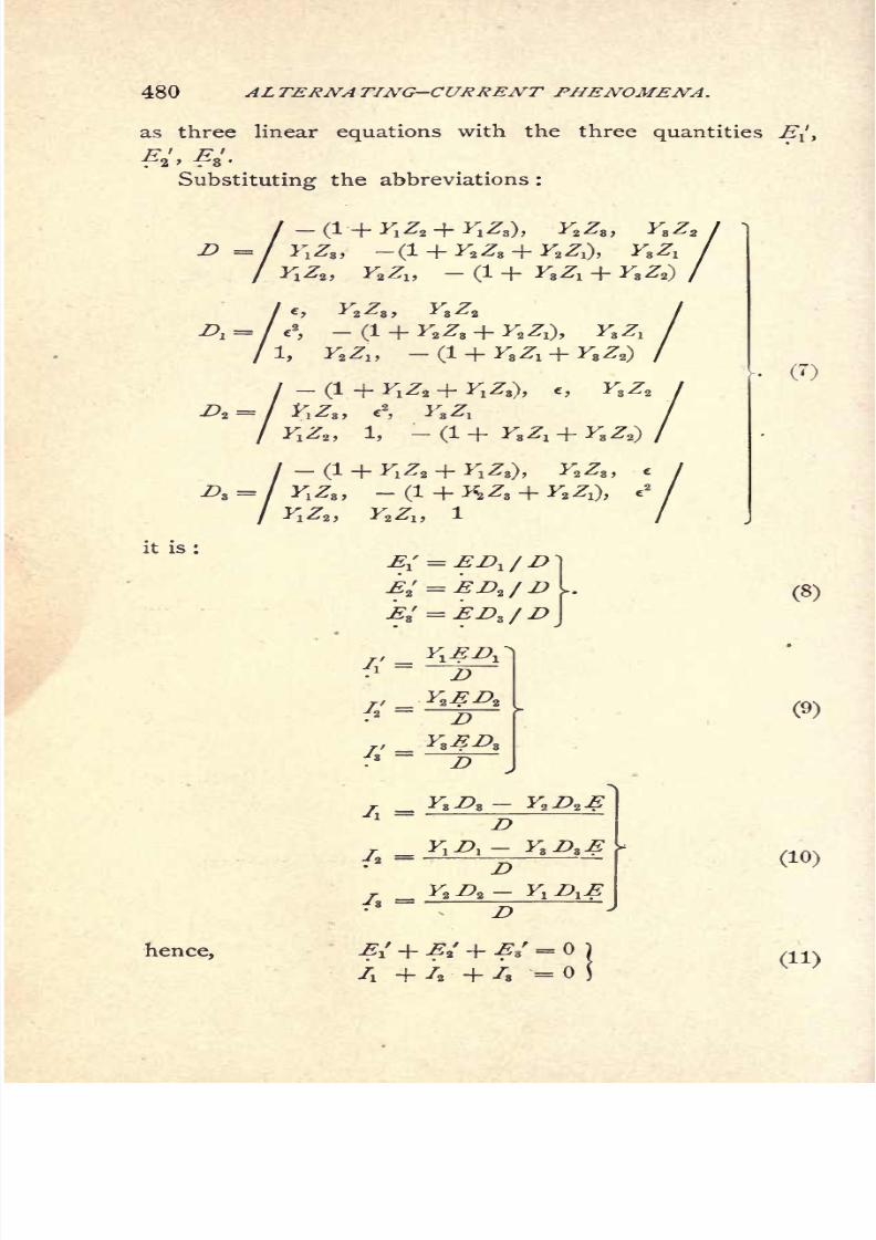
8/2/2019 Charles Steinmetz Theorycalculatio00steiiala
http://slidepdf.com/reader/full/charles-steinmetz-theorycalculatio00steiiala 506/557
480 ALTERNA TING-CURRENT PHENOMENA.
as three linear equations with the three quantities 2T/,
Substituting the abbreviations :
a I \7 7 I I/" 7 \ I/" 7 ~\7 7 i
~T * 1^2 ~T *1^3)> -tZ^S) *8^'2 I
7 V 7 /1_1_V7_1_V7 N>/^zt y2-^D V*
1 ~r -^s^i T *^V /
Ac, F
2
Z3 ,
F3
Z2
a
,-
(1 + ^^3 +, Y,Zlt -(1 + F
3Z1 +F3Z2)
-(1 + Y,Z2 + FiZ,), c, F3Z2
F.Z3, c2
,Yt Z,
Y.Z,, 1,-
(1 + F3ZX + F3Z2)
(i + ^iz. + yiz,),F
2
z3
,
A =/F
IZS ,
-(i
FZ2 ,F2ZX ,
it is:
D
72= i
__ F2 Z>2 -
hence,
(8)
(9)
(10)
(11)
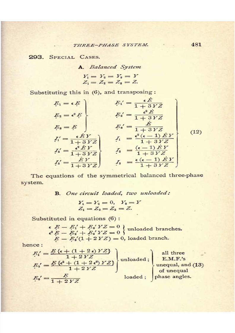
8/2/2019 Charles Steinmetz Theorycalculatio00steiiala
http://slidepdf.com/reader/full/charles-steinmetz-theorycalculatio00steiiala 507/557
THREE-PHASE SYSTEM.
293. SPECIAL CASES.
A. Balanced System
Y,= F2
= F8= F
Z, = Z2= Z3
= Z.
Substituting this in(6),
and transposing :
481
cE
s=
EI =
3FZ
1 + 3FZ
1 + 3YZEY
1 + 3KZJ
3FZ
3FZ
3 YZ
(12)
The equations of the symmetrical balanced three-phase
system.
B. One circuit loaded, two unloaded:
F! = F2=
0, F8= F
Zj = Z2= Z3
= Z.
Substituted in equations (6):
=( unloaded branches.
E E3'(l + 2 FZ) = 0, loaded branch.
hence :
r./
,
2KZ
2FZ
1 + 2 FZ
unloaded ;
loaded;
all three
KM.F.'s
unequal, and(13)
of unequal
phase angles.
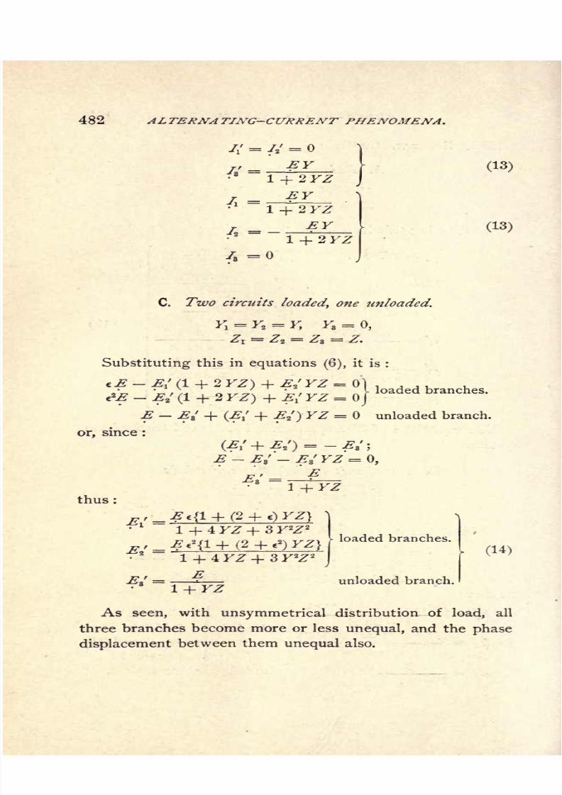
8/2/2019 Charles Steinmetz Theorycalculatio00steiiala
http://slidepdf.com/reader/full/charles-steinmetz-theorycalculatio00steiiala 508/557
482 ALTERNA TING-CURRENT PHENOMENA.
(13)
(13)
C. Two circuits loaded, one tinloaded.
F! = F2=
F, F8=
0,
Zt= Z2
= Z3= Z.
Substituting this in equations (6), it is :
eE E{ (1 + 2 FZ) + ./ FZ = 0)
E El (1 + 2 FZ) + E{ FZ = J
E s
'
+ (,,' + ^2')FZ = unloaded branch,
or, since :
E Ez
'' EZ'Y2:'= 0,
E 1 = ?\ + FZ
thus:
1 + 4 FZ + 3 F2Z 2
1 + 4 FZ + 3 F2Z 2
EI+'FZ
loaded branches.
unloaded branch.
(14)
As seen, with unsymmetrical distribution of load, all
three branches become more or less unequal, and the phase
displacement between them unequal also.

8/2/2019 Charles Steinmetz Theorycalculatio00steiiala
http://slidepdf.com/reader/full/charles-steinmetz-theorycalculatio00steiiala 509/557
QUARTER-PHASE SYSTEM. 483
CHAPTER XXXII.
QUARTER-PHASE SYSTEM.
294. In a three-wire quarter-phase system, or quarter-
phase system with common return wire of both phases, let
the two outside terminals and wires be denoted by 1 and 2>
the middle wire or common return by 0.
It is then :
EI
= E = E.M.F. between and 1 in thegenerator.Ez =jE = E.M.F. between and 2 in the generator.
Let:
./iand 72 = currents in 1 and in 2,
7 = current in 0,
Z-L and Zz= impedances of lines 1 and 2,
Z = impedance of line 0.
Yl and Y
2
= admittances of circuits to 1, and to 2,
// and //= currents in circuits to 1, and to 2,
Eia.-ndE2'=
potential differences at circuit to 1, and
to 2.
it is then, 7, -f 78 + 7 = ) v
or, I =-(/;+ 72) j
that is, 7 is common return of 7: and 72 .
Further, we have,
El =JE - 72 Z + Z =jE - 72 (Z2 + Z)- A
and
A = K, E{
(3)
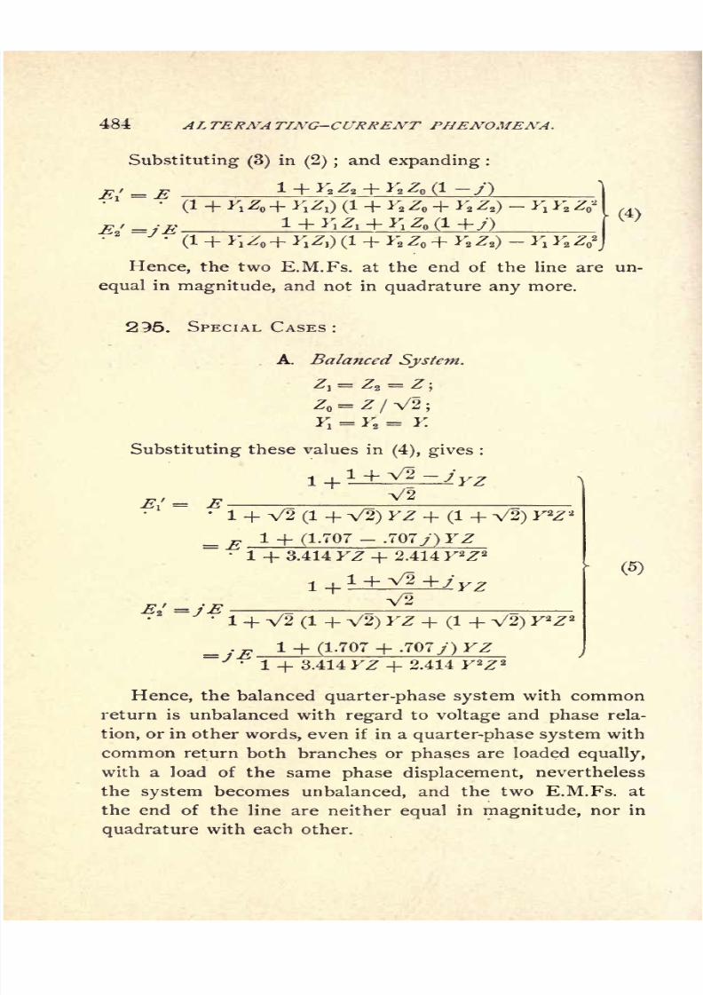
8/2/2019 Charles Steinmetz Theorycalculatio00steiiala
http://slidepdf.com/reader/full/charles-steinmetz-theorycalculatio00steiiala 510/557
484 AL TERNA TING-CURRENT PHENOMENA.
Substituting (3)in
(2) ;and expanding :
*/ - * _ l + F2 Z2 + F2 Z (l-y) _'. (
4)
2 /1_l_VX_l_V7'W'l_l_V7_l_V5^ V V '7 2
\*- i* 1^0 "T" *\**\)\~ i
* i ** T * i^ij *i *J ^o
Hence, the two E.M.Fs. at the end of the line are un-
equal in magnitude, and not in quadrature any more.
295. SPECIAL CASES :
A. Balanced System.
Z = Z/ V2 ;
F,= F
2= F
Substituting these values in(4), gives :
i +1 + V2-yrz
'
1 + V2 (1 + V2) FZ + (1 + V2) F2Z ;
_ E 1 + (1.707-
.707/) FZ1
+3.414
FZ +2.414
F
2
Z
2
(5)
V2~ J1 + V2 (1 + V2) FZ + (1 + V2) F
2Z 2
_ .^ 1 + (1.707 + .707.;) FZ'
1 + 3.414 FZ + 2.414 F 2Z 2
Hence, the balanced quarter-phase system with common
return is unbalanced with regard to voltage and phase rela-
tion, or in other words, even if in a quarter-phase system with
common return both branches or phases are loaded equally,
with a load of the same phase displacement, nevertheless
the system becomes unbalanced, and the two E.M.Fs. at
the end of the line are neither equal in magnitude, nor in
quadrature with each other.
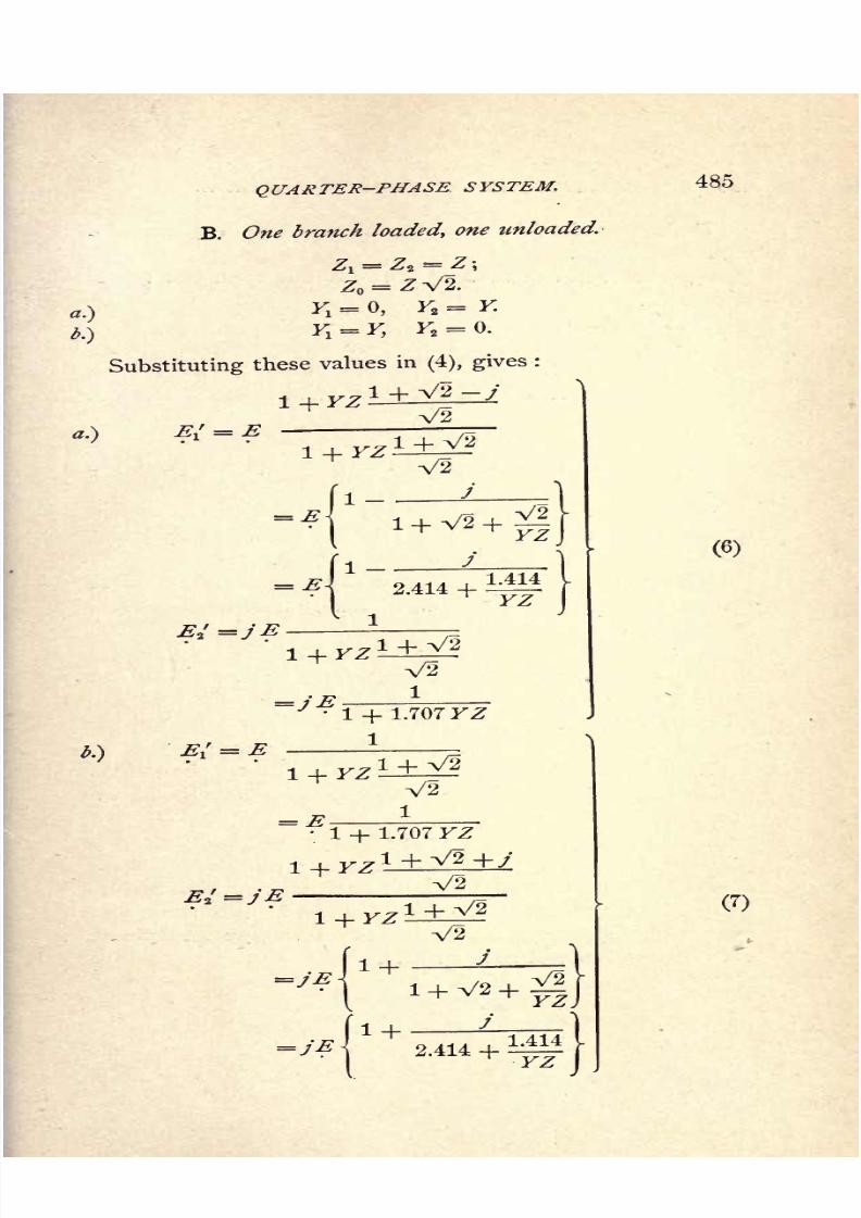
8/2/2019 Charles Steinmetz Theorycalculatio00steiiala
http://slidepdf.com/reader/full/charles-steinmetz-theorycalculatio00steiiala 511/557
QUARTER-PHASE SYSTEM.
B. One branch loaded, one unloaded.
485
a.)
b.)
Substituting these values in(4), gives :
i + V2 y
b.}
l + FZa.) 1
= EV2
1 + V2
V2
j
2.414 +1.414
YZ
*+'*f/
^l4-1.707FZ
1+^1^1 + 1.707 FZ
-t I ^/O1
+F2
V2
,
FZ
1 +
+
V2
2.414 +1.414
(6)

8/2/2019 Charles Steinmetz Theorycalculatio00steiiala
http://slidepdf.com/reader/full/charles-steinmetz-theorycalculatio00steiiala 512/557
486 ALTERNA TING-CURRENT PHENOMENA.
These two E.M.Fs. are unequal, and not in quadrature
with each other.
But the values in case a.) are different from the values
in case b.}.
That means :
The two phases of a three-wire quarter-phase system
are unsymmetrical, and the leading phase 1 reacts upon
the lagging phase 2 in a different manner than 2 reacts
upon 1.
It is thus undesirable to use a three-wire quarter-phase
system, except in cases where the line impedances Z are
negligible.
In all other cases, the four-wire quarter-phase system
is preferable, which essentially consists of two independent
single-phase circuits, and is treated as such.
Obviously, even in such an independent quarter-phase
system, at unequal distribution of load, unbalancing effects
may take place.
If one of the branches or phases is loaded differently
from the other, the drop of voltage and the shift of the
phase will be different from that in the other branch;and
thus the E.M.Fs. at the end of the lines will be neither
equal in magnitude, nor in quadrature with each other.
With both branches however loaded equally, the system
remains balanced in voltage and phase, just like the three-
phase system under the same conditions.
Thus the four-wire quarter-phase system and the three-
phase system are balanced with regard to voltage and phase
at equal distribution of load, but are liable to become un-
balanced at unequal distribution of load;
the three-wire
quarter-phase system is unbalanced in voltage and phase,
even at equal distribution of load.
8/2/2019 Charles Steinmetz Theorycalculatio00steiiala
http://slidepdf.com/reader/full/charles-steinmetz-theorycalculatio00steiiala 513/557
APPENDICES.
8/2/2019 Charles Steinmetz Theorycalculatio00steiiala
http://slidepdf.com/reader/full/charles-steinmetz-theorycalculatio00steiiala 514/557

8/2/2019 Charles Steinmetz Theorycalculatio00steiiala
http://slidepdf.com/reader/full/charles-steinmetz-theorycalculatio00steiiala 515/557
APPENDIX I.
ALGEBRA OF COMPLEX IMAGINARY
QUANTITIES.
INTRODUCTION.
296. The system of numbers, of which the science
of
algebratreats, finds its ultimate origin in experience.
Directly derived from experience, however, are only the
absolute integral numbers; fractions, for instance, are not
directly derived from experience, but are abstractions ex-
pressing relations between different classes of quantities.
Thus, for instance, if a quantity is divided in two parts,
from one quantity two quantities are derived, and denoting
these latter as halves expresses a relation, namely, that twoof the new kinds of quantities are derived from, or can be
combined to one of the old quantities.
297. Directly derived from experience is the operation
of counting or of numeration.
a, a + 1, a + 2, a + 3 . . . .
Counting by a given number of integers :
b integers
introduces the operation of addition, as multiple counting :
a
+b = c.
It is, a + b = b + a,
8/2/2019 Charles Steinmetz Theorycalculatio00steiiala
http://slidepdf.com/reader/full/charles-steinmetz-theorycalculatio00steiiala 516/557
490 APPENDIX 7.
that is, the terms of addition, or addenda, are interchange-
able.
Multiple addition of the same terms :
a -+- a -\- a -+- . . . + a = c
b equal numbers
introduces the operation of multiplication :
a x b = c.
It is, a X b = b X a,
that is, the terms of multiplication, or factors, are inter-
changeable.
Multiple multiplication of the same factors :
aX aX aX . . X a = c
b equal numbers
introduces the operation of involution :
Since abis not equal to #",
the terms of involution are not interchangeable.
298. The reverse operation of addition introduces the
operation of subtraction :
If a + 6 = f,
it is c b = a.
This operation cannot be carried out in the system of
absolute numbers, if :
b> c.
Thus, to make it possible to carry out the operation of
subtraction under any circumstances, the system of abso-
lute numbers has to be expanded by the introduction of
the negative number:_ = (_ 1) X ,
.where (- 1)
is the negative unit.
Thereby the system of numbers is subdivided in the

8/2/2019 Charles Steinmetz Theorycalculatio00steiiala
http://slidepdf.com/reader/full/charles-steinmetz-theorycalculatio00steiiala 517/557
COMPLEX IMAGINARY QUANTITIES. 491
positive and negative numbers, and the operation of sub-
traction possible for all values of subtrahend and minuend.From the definition of addition as multiple numeration, and
subtraction as its inverse operation, it follows :
c - (- b)= c + b,
thus: (-l)X (-!) = !;
that is, the negative unit is defined by, (I)2 = 1.
299. The reverse operation of multiplication introduces
the operation of division :
If a X b = c, then - = a.
b
In the system of integral numbers this operation can
only be carried out, if b is a factor of c.
To make it possible to carry out the operation of division
under any circumstances, the system of integral numbers
has to be expanded by the introduction of infraction:
:.where - is the integer fraction, and is defined by :
T- x b = 1.
300. The reverse operation of involution introduces two
new operations, since in the involution :
the quantities a and b are not reversible.
Thus V^ = <z, the evolution,
=b, the logarithmation.
The operation of evolution of terms c, which are not
complete powers, makes a further expansion of the system

8/2/2019 Charles Steinmetz Theorycalculatio00steiiala
http://slidepdf.com/reader/full/charles-steinmetz-theorycalculatio00steiiala 518/557
492 APPENDIX I.
of numbers necessary, by the introduction of the irrational
number(endless
decimalfraction), as
forinstance
:
V2 = 1.414213.
301. The operation of evolution of negative quantities
c with even exponents b, as for instance
2/-
makes a further expansion of the system of numbers neces-
sary, by the introduction of the imaginary unit.
-V^l
Thus -x/^ = -v/^T x #*.
where : V 1 is denoted by/.
Thus, the imaginary unity is defined by :
f =_ 1.
By addition and subtraction of real and imaginary units,
compound numbers are derived of the form :
which are denoted as complex imaginary mimbers.
No further system of numbers is introduced by the
operation of evolution.
The operation of logarithmation introduces the irrational
and imaginary and complex imaginary numbers also, but
no further system of numbers.
302. Thus, starting from the absolute integral num-
bers of experience, by the two conditions :
1st. Possibility of carrying out the algebraic operationsand their reverse operations under all conditions,
2d. Permanence of the laws of calculation,
the expansion of the system of numbers has become neces-
sary, into
Positive and negative numbers,
Integral numbers and fractions,
Rational and irrational numbers,
8/2/2019 Charles Steinmetz Theorycalculatio00steiiala
http://slidepdf.com/reader/full/charles-steinmetz-theorycalculatio00steiiala 519/557
COMPLEX IMAGINARY QUANTITIES. 493
Real and imaginary numbers and complex imaginary
numbers.Therewith closes the field of algebra, and all the alge-
braic operations and their reverse operations can be carried
out irrespective of the values of terms entering the opera-
tion.
Thus within the range of algebra no further extension
of the system of numbers is necessary or possible, and the
most general number is
a + jb.
where a and b can be integers or fractions, positive or
negative, rational or irrational.
ALGEBRAIC OPERATIONS WITH COMPLEX IMAGINARY
QUANTITIES.
303. Definition of imaginary unit:
f2 = - 1.
Complex imaginary number:
Substituting :
a = r cos(3
b = r sin(3,
it is A = r (cos /3 -f/ sin/?),
where r = a2 -- \
a
r = vector,
/3= amplitude of complex imaginary number A.
Substituting :
eJft 4- c-JPcos
sin/? =

8/2/2019 Charles Steinmetz Theorycalculatio00steiiala
http://slidepdf.com/reader/full/charles-steinmetz-theorycalculatio00steiiala 520/557
494 APPENDIX I.
it is A =reJP,
where c = lim (l + -}"= yJT
_1
= V n) o~lx2 X 3xis the basis of the natural logarithms.
Conjugate numbers :
a -\- j b = r (cos ft -\-j sinft)= reJ'P
and a jb = r (cos [/?]+> sin[ /?])
it is
Associate numbers:
a +jb = r (cos ft +/ sin/3)=
304. Addition and Subtraction :
Multiplication :
(a +jb) (a' +jb') = (aa1 - b
b') +j(ab' + ba')
or r(cos ^3 + /
sinft) X
r'
(cos /? + /sin
ftf)
= r r'
(cos [ -p
^]+ysin[/3 + ^]);
or reJ* X r'^'07 = rr'ef& + M.
Division :
Expansion of complex imaginary fraction, for rationaliza-
tion of denominator or numerator, by multiplication with
the conjugate quantity :
8/2/2019 Charles Steinmetz Theorycalculatio00steiiala
http://slidepdf.com/reader/full/charles-steinmetz-theorycalculatio00steiiala 521/557
COMPLEX IMAGINARY QUANTITIES. 495*"
a+jb = (a+jb}(a' -jb'} = (aar+ bb'} +j (b a'- ab'}
-jb'} , *" + *"
(a! -f j b'} (a jb} (a a' + bb'} +j(ab' b
a')
'
or,_ r ^_p ^ _^ .
r'
or>
r
involution :
(a +jbY = {r (cos
evolution :
-v/^- (cos /8
+ ysin
305. Roots of the Unit :
=+l, -1;
</I=+i, -i, +y, -y ;
'
+i+y +i-y -i +yV2 V2 V2
-i-yV2
'
306. Rotation :
In the complex imaginary plane,
multiplication with
9 * 2-n-
VI = cos +y sin = e
means rotation, in positive direction, by 1/n of a revolution,
8/2/2019 Charles Steinmetz Theorycalculatio00steiiala
http://slidepdf.com/reader/full/charles-steinmetz-theorycalculatio00steiiala 522/557
496 APPENDIX I.
multiplication with (1) means reversal, or rotation by 180,
multiplication with (+y ) means positive rotation by 90,
multiplication with( /) means negative rotation by 90.
307. Complex imaginary plane :
While the positive and negative numbers can be rep-
resented by the points of a line, the complex imaginary
numbers are represented by the points of a plane, with the
horizontal axis A' O A as real axis, the vertical axis Br
O Bas imaginary axis. Thus all
the positive real numbers are represented by the points of half
axis OA towards the right ;
the negative real numbers are represented by the points of half
axis OA' towards the left;
the positive imaginary numbers are represented by the points of
half axis OB upwards ;
the negative imaginary numbers are represented by the points of
half axis OB' downwards;
the complex imaginary numbers are represented by the points
outside of the coordinate axes.
8/2/2019 Charles Steinmetz Theorycalculatio00steiiala
http://slidepdf.com/reader/full/charles-steinmetz-theorycalculatio00steiiala 523/557
APPENDIX II.
OSCILLATING CURRENTS.
INTRODUCTION.
308. An electric current varying periodically between
constant maximum and minimum values, that is, in equal
time intervalsrepeating
the samevalues,
is called an
alternating current if the arithmetic mean value equals
zero;and is called a pulsating current if the arithmetic
mean value differs from zero.
Assuming the wave as a sine curve, or replacing it by
the equivalent sine wave, the alternating current is charac-
terized by the period or the time of one complete cyclic
change, and the amplitude or the maximum value of the
current. Period and amplitude are constant in the alter-
nating current.
A very important class are the currents of constant
period, but geometrically varying amplitude ;that is, cur-
rents in which the amplitude of each following wave bears
to that of the preceding wave a constant ratio. Such
currents consist of a series of waves of constant length,
decreasing in amplitude, that is in strength, in constant
proportion. They are called oscillating currents in analogy
with mechanical oscillations, for instance of the pendu-
lum, in which the amplitude of the vibration decreases
in constant proportion.
Since the
amplitude
of the oscillating current varies,
constantly decreasing, the oscillating current differs from

8/2/2019 Charles Steinmetz Theorycalculatio00steiiala
http://slidepdf.com/reader/full/charles-steinmetz-theorycalculatio00steiiala 524/557
498 APPENDIX II.
the alternating current in so far that it starts at a definite
time, and gradually dies out, reachingzero value theoreti-
cally at infinite time, practically in a very short time, short
even in comparison with the time of one alternating half-
wave. Characteristic constants of the oscillating current
are the period T or frequency N =1/7", the first ampli-
tude and the ratio of any two successive amplitudes, the
latter being called the decrement of the wave. The oscil-
lating current will thus be represented by the product of
a periodic function, and a function decreasing in geometric
proportion with the time. The latter is the exponential
function A f ~ gt.
309. Thus, the general expression of the oscillating
current is
/= ^/-0'COS (2-rrNt S),
since A'-** = A'A-'* = U~ bt.
Where e = basis of natural logarithms, the current may
be expressed
7= i(.~bt cos (2-n-JVf )
= ze- a * cos(<#>
-),
where <#>= %-nNt; that is, the period is represented by a
complete revolution.

8/2/2019 Charles Steinmetz Theorycalculatio00steiiala
http://slidepdf.com/reader/full/charles-steinmetz-theorycalculatio00steiiala 525/557
OSCILLATING CURRENTS. 499
In the same way an oscillating electromotive force will
be represented by
E = etr a * cos O 5).
Such an oscillating electromotive force for the values
e = 5, a = .1435 or- 2 =
.4,=
0,
is
represented
in rectangular coordinates in Fig. 207, and
in polar coordinates in Fig. 208. As seen from Fig. 207,
the oscillating wave in rectangular coordinates is tangent
to the two exponential curves,
Fig. 208.
310. In polar coordinates, the oscillating wave is repre-
sented in Fig. 208 by a spiral curve passing the zero point
twice per period, and tangent to the exponential spiral,
The latter is called the envelope of a system O.L oscillat-
ing waves of which one is shown separately, with the same
constants as Figs. 207 and 208, in Fig. 209. Its character-
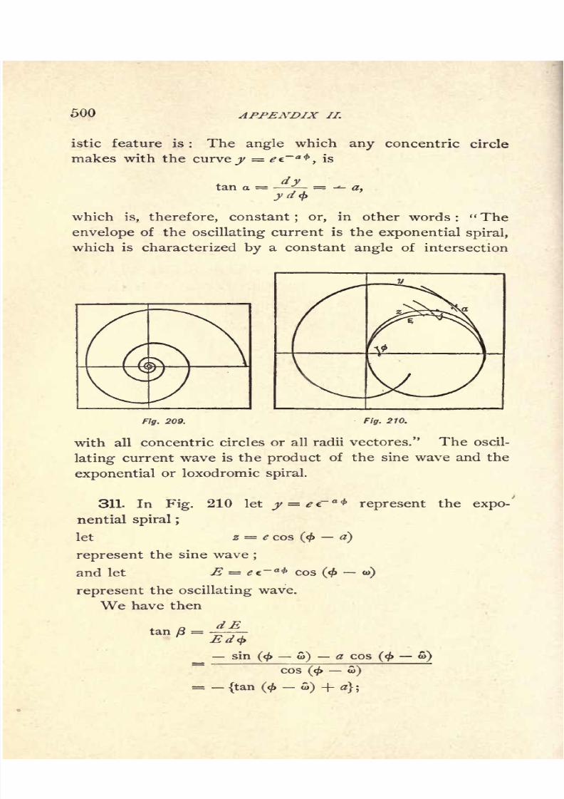
8/2/2019 Charles Steinmetz Theorycalculatio00steiiala
http://slidepdf.com/reader/full/charles-steinmetz-theorycalculatio00steiiala 526/557
500 APPENDIX II.
istic feature is : The angle which any concentric circle
makes with the curve y ee~a<t
>, is
tan a =
which is, therefore, constant; or, in other words :
" The
envelope of the oscillating current is the exponential spiral,
which is characterized by a constant angle of intersection
Fig. 209. Fig. 210.
with all concentric circles or all radii vectores." The oscil-
lating current wave is the product of the sine wave and the
exponential or loxodromic spiral.
311. In Fig. 210 let j/= e~ a<t>
represent the expo-'
nential spiral ;
let z = e cos(< a)
represent the sine wave;
and let E = ef.-** cos (< w)
represent the oscillating wave.
We have then
tan y3=Ed*
_ sin(< w) a cos
COS(< oi)
={tan (<^> ) + a} ;
to)
8/2/2019 Charles Steinmetz Theorycalculatio00steiiala
http://slidepdf.com/reader/full/charles-steinmetz-theorycalculatio00steiiala 527/557
OSCILLATING CURRENTS. 501
that is, while the slope of the sine wave, z = e cos(< w),
is represented bytan y
= tan(< w),
the slope of the exponential spiral y = ei' * is
tan a = a = constant.
That of the oscillating wave E = *?e~a * cos
(< to)is
tan /3=
{tan (< w) + a}.
Hence, it is increased over that of the alternating sine
wave by the constant a. The ratio of the amplitudes of
two consequent periods is
A is called the numerical decrement of the oscillating
wave, a the exponential decrement of the oscillating wave,
a the angular decrement of the oscillating wave. The
oscillating wave can be represented by the equation
= ec-**" cos ($ 5).
In the instance represented by Figs. 181 and 182> we
have A =.4, a = .1435, a = 8.2.
Impedance and Admittance.
312. In complex imaginary quantities, the alternating
wave* = e cos (*
-ffl)
is represented by the symbol
E = e (cos w -\-j sin w) = <?x -\-jez .
By an extension of the meaning of this symbolic ex-
pression, the oscillating wave E = ee~ a<t> cos(<f> w) can
be expressed by the symbol
E = e (cos w -\-j sin w) dec a = (e -\-j'e^)dec a,
where a = tan a is the exponential decrement, a the angular
decrement, e~27ra the numerical decrement.

8/2/2019 Charles Steinmetz Theorycalculatio00steiiala
http://slidepdf.com/reader/full/charles-steinmetz-theorycalculatio00steiiala 528/557
502 APPENDIX II.
Inductance.
313. Let r = resistance, L = inductance, and x =2 ITNL = reactance.
In a circuit excited by the oscillating current,
/= /-* cos(< w)
=/(cos to +y sin w) dec a =
(*i -\-J*z) dec a,
where /i= / cos w, /2
= / sin>,
a = tan a.
We have then,
The electromotive force consumed by the resistance r of
the circuit ^
The electromotive force consumed by the inductance Lof the circuit,
Ef**L~*iNI&t=
*.dt d<$> d<$>
Hence Ex = xif.~ a^>
(sin (<J> fy -\- a cos(< w)}
xi(.~ a ^. ,.
, N= sin (^>w
-f- a).COS a
Thus, in symbolic expression,
x= -
^{sin (w a) +/ cos (w a)} dec a
COS a
= x i (a -f y) (cos w + 7 sina>)
dec a;
that is,Ex= x I (a +/') dec a .
Hence the apparent reactance of the oscillating current
circuit is, in symbolic expression,
X = x(a +y') dec a.
Hence it contains an energy component ax, and the
impedance is
Z = (r X) dec a = {r x (a +/')} dec a = (r ax jx) dec a.
Capacity.
314. Let r = resistance, C = capacity, and xc= 1 /2-n-JVC
= capacity reactance. In a circuit excited by the oscillating
8/2/2019 Charles Steinmetz Theorycalculatio00steiiala
http://slidepdf.com/reader/full/charles-steinmetz-theorycalculatio00steiiala 529/557
OSCILLATING CURRENTS. 503
current /, the electromotive force consumed by the capacity
Cis
or, by substitution,
Ex = x I * e~a * cos(<
{sin (< w) a COS(<
oi2
(1 +2
)COS a
hence, in symbolic expression,
sin(</>
u>a) ;
=2 ( + /) (cos
w +y sin w) dec a;
hence,
that is, the
apparent capacityreactance of the
oscillatingcircuit is, in symbolic expression,
dec
315. We have then:
In an oscillating current circuit of resistance r, induc-
tive reactance x, and capacity reactance xc , with an expo-
nential decrement a, the apparent impedance, in symbolic
expression, is :
*'
1 +a2/ V 1 +**
= ra jxa ;

8/2/2019 Charles Steinmetz Theorycalculatio00steiiala
http://slidepdf.com/reader/full/charles-steinmetz-theorycalculatio00steiiala 530/557
504 APPENDIX 77.
and, absolute,
Admittance.
316. Let /= / e -a* cos ^_ ) ==current<
Then from the preceding discussion, the electromotive force
consumed by resistance r, inductive reactance x, and capa-
city reactance xc ,
is
cos $ r axa*
e sin(<
= iza (.~a ^ cos
(<w + 8),
where tan 8 = i_^,
ar ax
.
-Xf
substituting & + 8 for G, and ^ = /^a we have
cos <>
I = e~a *
cos (<#> w 8)
,1 \ cos 8 / i ~\ isin 8 .
/ ,= e e.a<p
\cos (9 to
) -jsin (9
hence in complex quantities,
E = e (cos u> -\-j sinoi)
dec a,
+sin
8/2/2019 Charles Steinmetz Theorycalculatio00steiiala
http://slidepdf.com/reader/full/charles-steinmetz-theorycalculatio00steiiala 531/557
OSCILLATING CURRENTS. 505
or, substituting,
r ax
I=E
I-dec a.
317. Thus in complex quantities, for oscillating cur-
rents, we have : conductance,
susceptance,
admittance, in absolute values,
/ o i To 1
in symbolic expression,
Y=g+J
1 + a2/ \ 1 + a2
'
Since the impedance is
Z = ir ax
we have
8/2/2019 Charles Steinmetz Theorycalculatio00steiiala
http://slidepdf.com/reader/full/charles-steinmetz-theorycalculatio00steiiala 532/557
506 APPENDIX II.
that is, the same relations as in the complex quantities in
alternating-current circuits, except that in the present case
all the constants ra ,xa ,
za , g, z, y, depend upon the dec-
rement a.
Circuits of Zero Impedance,
318. In an oscillating-current circuit of decrement a, of
resistance r, inductive reactance x, and capacity reactance xc,
the impedance was represented in symbolic expression by
-jxa=
! +or numerically by
Thus the inductive reactance x, as well as the capacity
reactance xc,
do not represent wattless electromotive forces
as in an alternating-current circuit, but introduce energy
components of negative sign
aax -- x :
1 + a2
that means,
" In an oscillating-current circuit, the counter electro-
motive force of self-induction is not in quadrature behind
the current, but lags less than 90, or a quarter period; and
the charging current of a condenser is less than 90, or a
quarter period, ahead of the impressed electromotive force."
319. In consequence of the existence of negative en-
ergy components of reactance in an oscillating-current cir-
cuit, a phenomenon can exist which has no analogy in an
alternating-current circuit;that is, under certain conditions
the total impedance of the oscillating-current circuit can
equal zero :
In this case we have
r - ax;x --^ = 0,c
1 a2 1 + fl
a

8/2/2019 Charles Steinmetz Theorycalculatio00steiiala
http://slidepdf.com/reader/full/charles-steinmetz-theorycalculatio00steiiala 533/557
OSCILLATING CURRENTS. 507
substituting in this equation
x = 2 TTNL xc =
and expanding, we have
a
That is,
"If in an oscillating-current circuit, the decrement
1
and the frequency N = r/4iraL, the total impedance of
the circuit is zero;
that is, the oscillating current, when
started once, will continue without external energy being
impressed upon the circuit."
320. The physical meaning of this is :
"If upon an
electric circuit a certain amount of energy is impressed
and then the circuit left to itself, the current in the circuit
will become oscillating, and the oscillations assume the fre-
quency N =r/4:7raL, and the decrement
1
That is, the oscillating currents are the phenomena by
which an electric circuit of disturbed equilibrium returns to
equilibrium.
This feature shows the origin of the oscillating currents,
and the means to produce such currents by disturbing
the equilibrium of the electric circuit;
for instance, by
the discharge of a condenser, by make and break of the
circuit, by sudden electrostatic charge, as lightning, etc.
Obviously, the most important oscillating currents are

8/2/2019 Charles Steinmetz Theorycalculatio00steiiala
http://slidepdf.com/reader/full/charles-steinmetz-theorycalculatio00steiiala 534/557
508 APPENDIX II.
those flowing in a circuit of zero impedance, representing
oscillating discharges of the circuit. Lightning strokes
usually belong to this class.
Oscillating Discharges.
321. The condition of an oscillating discharge is
Z = 0, that is,
~ ~ / .1 r
2aL 2Z~ ~ 1 '
If r = 0, that is, in a circuit without resistance, we have
a = 0, Af= 1/2 TT VZT
;that is, the currents are alter-
nating with no decrement, and the frequency is that of
resonance.
If 4H r2 C - 1 < 0, that is, r > 2 V2T/T, a and Nbecome imaginary ;
that is, the discharge ceases to be os-
cillatory.An electrical discharge assumes an oscillating
nature only, if r < 2 V/,/C. In the case r = 2 VZ,
/C we
have = oo,
./V =;that is, the current dies out without
oscillation.
From theforegoing
we have seen thatoscillating
dis-
charges, as for instance the phenomena taking place if
a condenser charged to a given potential is discharged
through a given circuit, or if lightning strikes the line
circuit, are denned by the equation : Z = dec a.
Since
/ =(/V+y/a) dec a, Er = Ir dec a,
Ex =-x I (a +/) dec a, Exc=_^L_/(-
a +/) dec a,
we haver -a X --^ Xc = ^
I + a?
hence, by substitution,
Exc= x /( a +/) dec a.

8/2/2019 Charles Steinmetz Theorycalculatio00steiiala
http://slidepdf.com/reader/full/charles-steinmetz-theorycalculatio00steiiala 535/557
OSCILLATING CURRENTS. 50'
The two constants, t\and z'
2 ,of the discharge, are deter-
mined bythe initial
conditions,that
is,
the electromotive
force and the current at the time t = 0.
322. Let a condenser of capacity C be discharged
through a circuit of resistance r and inductance L. Let
e = electromotive force at the condenser in the moment
of closing the circuit, that is, at the time t or < = 0.
A.t this moment the current is zero;
that is,
7=//2 ,/1== 0.
Since Exe= */( a +/) dec a = e at
<f>= 0,
we have x /2 Vl + a 2 = e or /2= = .
x V 1 + a2
Substituting this, we have,
I je
dec a, Er =jer
dec a,
x Vl + a2 x Vl + az
Ex= e
(1 -ja) dec a, ^c= e
(1 +/ ) dec a,
Vl + 8 Vl + a2
the equations of the oscillating discharge of a condense
of initial voltage e.
Since x = 2 * NL,
1
we have
x =
hence, by substitution,
ldec a,

8/2/2019 Charles Steinmetz Theorycalculatio00steiiala
http://slidepdf.com/reader/full/charles-steinmetz-theorycalculatio00steiiala 536/557
.510 APPENDIX II.
E - ef\fCf^r-, rr~ \/ ~r~
47TZ
the final equations of the oscillating discharge, in symbolic
expression.
Oscillating Current Transformer.
323. As an instance of the application of the symbolic
method of analyzing the phenomena caused by oscillating
currents, the transformation of such currents may be inves-
tigated. If an oscillating current is produced in a circuit
including the primary of a transformer, oscillating currents
will alsoflow in the
secondaryof this
transformer.In
atransformer let the ratio of secondary to primary turns be/.
Let the secondary be closed by a circuit of total resistance,
i\= r{ -\- TJ",where
1\= external, 1\'
= internal, resistance.
The total inductance Ll= Z/ -f /,/',
where Z/ = external,
Zj"= internal, inductance
;total capacity, Cv Then the
total admittance of the secondary circuit is
)dec a =
where xl= 2irJVL
l= inductive reactance: x
cl= \l1-jrNC
' =
capacity reactance. Let rQ= effecive hysteretic resistance,
Z = inductance ; hence, x^= Z-n-NL Q
= reactance; hence,
admittance
of the primary exciting circuit of the transformer ;that is,
the admittance of the primary circuit at open secondary
circuit.
As discussed elsewhere, a transformer can be considered
as consisting of the secondary circuit supplied by the im-
pressed electromotive force over leads, whose impedanceis

8/2/2019 Charles Steinmetz Theorycalculatio00steiiala
http://slidepdf.com/reader/full/charles-steinmetz-theorycalculatio00steiiala 537/557
OSCILLATING CURRENTS. 511
equal to the sum of primary and secondary transformer im-
pedance, and which are shunted by the exciting circuit, out-
side of the secondary, but inside of the primary impedance.
Let r = resistance;L = inductance
;C =
capacity ;
hence'
x = 2 TT NL = inductive reactance,
xc= 1 /
2 TTN C = capacity reactance of the total primary
circuit, including the primary coil of the transformer. If
EI = EI dec a denotes the electromotive force induced in
the secondary of the transformer by the mutual magnetic
flux;
that is, by the oscillating magnetism interlinked
with the primary and secondary coil, we have Iv= E^ Yl
dec a = secondary current.
Hence, //= / 7
Xdec a = pEJ Yl
dec a = primary load
current, or component of primary current corresponding to
secondary current. Also, 7 = -2j/ F dec a = primary
/'
exciting current; hence, the total primary current is
/= // + 7 =-'{Fo +/
2
Y,} dec a.
E'E' = -^-i- dec a = induced primary electromotive force.
/Hence the total primary electromotive force is
E = (' + /Z) dec a = L(1 + Z F +/2Z Y,} dec a.
P
In an oscillating discharge the total primary electro-
motive force E =;that is,
or, the substitution
a
1 +(r- ax
) -.
. .
8/2/2019 Charles Steinmetz Theorycalculatio00steiiala
http://slidepdf.com/reader/full/charles-steinmetz-theorycalculatio00steiiala 538/557
512 APPENDIX II.
Substituting in this equation, ^r=2 itN C, xc=
~L/'2
etc., we get a complex imaginary equation with the two
constants a and N. Separating this equation in the real
and the imaginary parts, we derive two equations, from
which the two constants a and N of the discharge are
calculated.
324. If the exciting current of the transformer is neg-
ligible, that is, if YQ = 0, the equation becomes essentially
simplified,
I a \ . I x \(r a x xc 1 j ( x I
1+/2v 1 + *
8i v Ljt^l =0
;
that is,
or, combined,
(r, -2a Xl) +/2
(r-2 ax) = 0,
Substituting for xlt x, xel ,xeiwe have
+/a
Z)+/V / 4(A+/+/2
Z) V (n +/V)2
(Ci
!}dec a,
7 =pEi YI dec a,
/! = ^/ F! dec a,
the equationsof
the oscillating-current transformer, withE{ as parameter.
8/2/2019 Charles Steinmetz Theorycalculatio00steiiala
http://slidepdf.com/reader/full/charles-steinmetz-theorycalculatio00steiiala 539/557
INDEX.
PAGE
Addition 494. 498
Admittance, conductance, suscep-
tance, Chap. vn. ... 52
definition 53
parallel connection ... 57
primary exciting, of trans-
former 204
of induction motor . . . 240
Advance of phase, hysteretic . .115
Algebra of complex imaginary
Quantities, App. I. . . . 489
Alternatingcurrent
generator,Chap, xvii 297
transformer, xiv 193
motor, commutator, Chap.
xx 354
motor, synchronous, Chap.
xix 321
Alternating wave, definition . . 11
general ..."... . 7
Alternators, Chap. xvii.. . .
297
parallel operation, Chap.
xvin 311
series operation 313
synchronizing, Chap. xvin. . 311
synchronizing power in paral-
lel operation 317
Ambiguity of vectors .... 43
Amplitude of alternating wave . 7
Angle of brush displacement in
repulsion motor .... 361
Apparent total impedance of
transformer 208
Arc, distortion of wave shape by 394
power factor of 395
Arithmetic mean value, or average
value of alternating wave 11
Armature reaction of alternators
and synchronous motors . 297
Armature reaction of alternators,
as affecting parallel opera-
tion 313
self-induction of alternators
and synchronous motors . 300
slots, number of, affecting
wave shape 384
Associate numbers 494
Asynchronous, see induction . .
Average value, or mean value of
alternating wave .... 11
Balance, complete, of lagging
currents by shunted con-
densance 74
Balanced and unbalanced poly-
phase systems, Chap.
xxvii 440
Balanced polyphase system . . 431
quarter-phase system . . . 484
three-phase system . . .
481Balance factor of polyphase sys-
tem 441
of lagging currents by shun-
ted condensance ... 75
Biphase, see quarter-phase . .
Cables, as distributed capacity . 158
with resistance and capacity
topographic circuit charac-
teristic 47
Calculation of magnetic circuit
containing iron . . . 125
of constant frequency induc-
tion generator .... 269
of frequency converter . . 232
of induction motor . . . 262
of single-phase induction mo-
tor . . 287
8/2/2019 Charles Steinmetz Theorycalculatio00steiiala
http://slidepdf.com/reader/full/charles-steinmetz-theorycalculatio00steiiala 540/557
514 INDEX.
Calculation of transmission lines,
Chap, ix 83
Capacity and inductance, dis-
tributed, Chap. xin. . . 158
as source of reactance . . 6
in shunt, compensating for
lagging currents .... 72
intensifying higher harmon-
ics 402
see condenser and conden-
sance.
Chain connection of induction
motors, or concatenation . 274
Characteristic circuit of cable
with resistance and capa-
city 48
circuit of transmission line
with resistance, inductance,
capacity, and leakage . .
49curves of transmission lines . 172
field of alternator .... 304
power of polyphase systems 447
Circuit characteristic of cable
with resistance and capa-
city 48
characteristic of transmission
line with resistance, induc-
tance, capacity and leakage 49
factor of distorted wave . . 415
with series impedance . . 68
with series reactance ... 61
with series resistance ... 58
Circuits containing resistance, in-
ductance, and capacity,
Chap, vin 58
Coefficient of
hysteresis
. . 116
Combination of alternating sine
waves by parallelogram or
polygon of vectors ... 21
of double frequency vectors,
as power 163
of sine waves by rectangular
components 35
of sine waves in symbolic
representation .... 38Commutator motor, Chap. xx. 354
Compensation for lagging cur-
rents by shunted conden-
sance 72
Complete diagram of transmis-
sion line in space . . .192
Complex imaginary number . . 492
imaginary quantities, algebra
of, App. i 489
imaginary quantities, as sym-
bolicrepresentation
of al-
ternating waves .... 37
quantity Chap, v 33
Compounding curve of frequency
converter 232
Concatenated couple of induction
motors, calculation . . . 276
Concatenation of induction mo-
tors 274
Condensance in shunt, compen-
sating for lagging currents 72
in symbolic representation . 40
or capacity reactance ... 6
see capacity and condenser
Condensers, distortion of wave
shape by 393
see capacity and condensance
with distorted wave . . . 419
with single-phase induction
motor 286
Conductance, effective, definition 104
in alternating current cir-
cuits, definition .... 54
in continuous current cir-
cuits 52
of receiver circuit, affecting
output of inductive line . 89
parallel connection ... 52
see resistance
Conjugate numbers 494
Constant current constant po-
tential transformation . . 76
current, constant potential
transformation by trans-
mission line 181
potential, constant currenttransformation . . 76
8/2/2019 Charles Steinmetz Theorycalculatio00steiiala
http://slidepdf.com/reader/full/charles-steinmetz-theorycalculatio00steiiala 541/557
INDEX. 515
Constant potential, constant cur-
rent transformation by
transmission line .... 181
rotating M M.F 436
Constants, characteristic, of in-
duction motor .... 262
Continuous current system, distri-
bution efficiency .... 473
Control, by change of phase, of
transmission line, Chap. ix. 83of receiver circuit by shunted
susceptance 96
Converter of frequency, Chap.
xv 219
Counter E.M.F. constant in syn-
chronous motor .... 349
of impedance 25
of inductance 25
of resistance .25of self-induction ..... 24
Counting or numeration . . . 489
Cross-flux, magnetic, of trans-
former 193
of transformer, use for con-
stant power or constant
current regulation . . . 194
Current, minimum, in synchro-
nous motor 345
waves, alternating, distorted
by hysteresis 109
Cycle, or complete period ... 10
Decrement of oscillating wave . 501
Delta connection of three-phase
system 453
current in threephase system
455
potential of three-phase sys-
tem 455
Y connection of three-phase
transformation .... 463
Demagnetizing effect of armature
reaction of alternators and
synchronous motors . . 298
effect of eddy currents . . 136
Dielectric and electrostatic phe-
nomena . . 144
Dielectic and electrostatic
hyste-resis 145
Diphase, see quarter-phase.
Discharge, oscillating .... 508
Displacement angle of repulsion
motor 361
of phase, maximum, in syn-
chronous motor .... 347
Distorted wave, circuit factor . 415
wave, decreasing hysteresis
loss 407
wave, increasing hysteresis
loss 407
wave of condenser .... 419
wave of synchronous motor . 422
wave, some different shapes . 401
wave, symbolic representa-
tion, Chap. xxiv. . . . 410
wave, in induction motor . . 426
Distortion of alternating wave . 9
of wave shape and eddy cur-
rents 408
of wave shape, and insulation
strength 409
of wave shape and its causes,
Chap, xxn 383
of wave shape by hysteresis . 109
of wave shape, effect of,
Chap, xxin 398
of wave shape, increasing ef-
fective value 405
Distributed capacity, inductance,
resistance, and leakage,
Chap, xni 158
Distribution efficiency of systems. 468
Dividedcircuit, equivalent
to
transformer 209
Division 491,494
Double delta connection of three-
phase six-phase transfor-
mation 465
frequency quantities, as pow-
er, Chap, xii 150
frequency values of distorted
wave, symbolic representa-
tion . . 413

8/2/2019 Charles Steinmetz Theorycalculatio00steiiala
http://slidepdf.com/reader/full/charles-steinmetz-theorycalculatio00steiiala 542/557
516 INDEX.
Double peaked wave 399
saw-tooth wave 399
T connection of three-phase
six-phase transforma-
tion 466
Y connection of three-phase
six-phase transforma-
tion 466
.Eddy currents, unaffected bywave-shape distortion . . 408
demagnetizing or screening
effect 136
in conductor, and unequal
current distribution . . . 139
Eddy or Foucault currents, Chap.
xi 129
Effective reactance and suscep-
tance, definition .... 105
resistance and conductance,
definition 104
resistance and reactance,
Chap, x 104
to maximum value .... 14
value of alternating wave . 11
value of alternating wave,
definition 14
value of general alternating
wave 15
Effects of higher harmonics,
Chap, xxin 398
Efficiency, maximum, of induc-
tive line 93
Efficiency of systems, Chap. xxx. 468
Electro-magnetic induction, law
of, Chap.Ill 16
.Electrostatic and dielectric phe-
nomena 144
hysteresis 145
Energy component of self-induc-
tion 372
flow of, in polyphase system, 441
Epoch of alternating wave ... 7
Equations, fundamental, of alter-
nating current transformer,
208, 225
Eauations, fundamental, ofgen-
eral alternating current
transformer, or frequency
converter 224
of induction motor . . 226, 242
of synchronous motor . . . 339
of transmission line . . . 169
Equations, general, of apparatus,
see equations,fundamental.
Equivalence of transformer withdivided circuit 209
Equivalent sine wave of distorted
wave inEvolution 491, 495
Exciting admittance of induction
motor 240
admittance of transformer . 204
current of magnetic circuit,
distorted by hysteresis. .111
current of transformer . . 195
Field characteristic of alternator . 304
First harmonic, or fundamental,
of general alternatingwave, 8
Five-wire single-phase system, dis-
tributionefficiency . . . 470
Flat-top wave 399
Flow of power in polyphase sys-
tem 441
Foucault or Eddy currents, Ch. xi. 129
Four-phase, seequarter-phase.
Fraction 491
Free oscillations of circuit . . . 508
Frequency converter, Chap. xv. . 219
converter, calculation . . .232
converter, fundamental equa-tions 224
of alternating wave ... 7
ratio of general alternating
current transformer or fre-
quency converter . . . 221
Friction, molecular magnetic . . 106
Fundamental equations, see equa-
tions, fundamental,
frequency of transmission
line discharge . . . .186
8/2/2019 Charles Steinmetz Theorycalculatio00steiiala
http://slidepdf.com/reader/full/charles-steinmetz-theorycalculatio00steiiala 543/557
INDEX. 517
Fundamental equations, or first
harmonic of general alter-
nating wave 8
General alternating current trans-
former, or frequency con-
verter, Chap. xv. ... 219
alternating wave . . . . 7, 8
alternating wave, symbolic
representation,Chap.xxiv.410
equations, see equations, fun-
damental.
polyphase systems, Chap.
xxv 430
Generator action of concatenated
couple 280
of reaction machine . . .377
alternating current, Chap.
xvn 297
synchronous, operating with-
out field excitation . . . 371
induction 265
induction, calculation for con-
stant frequency .... 269
reaction, Chap. xxi. . . .371
vector diagram 28
Graphical construction of circuit
characteristic . . . . 48, 49
Graphic representation, Chap. iv. 19
limits of method .... 33
see polar diagram.
Harmonics, higher, effects of,
Chap, xxin 398
higher, resonance rise in
transmission lines . . . 402
of general alternating wave . 8
Hedgehog transformer .... 195
Hemisymmetrical polyphase sys-
tem 439
Henry, definition of 18
Hexaphase, see six-phase.
Hysteresis, Chap, x 104
advance of phase . . . .115
as energy component of self-
induction 372
Hysteresis, coefficient . . . .116
cycle or loop 107
dielectric, or electrostatic . 145
energy current of transformer 196
loss, effected by wave shape, 407
loss in alternating field . .114
magnetic 106
motor 293
of magnetic circuit, calcula-
tion125
or magnetic energy current . 115
Imaginary number 492
quantities, complex, algebra
of, App. 1 489
Impedance 2
in series with circuit ... 68
in symbolic representation . 39
primary and secondary, of
transformer 205
see, admittance.
series connection .... 57
total apparent, of transformer 208
Independent polyphase system . 431
Inductance 4
definition of 18
factors of distorted wave . . 415
mutual'
... 142
Induction, electro-magnetic,law of 16
electrostatic 147
generator 265
generator, calculation for
constant frequency . . 269
generator, driving synchron-
ous motor 272
motor, Chap,xvi 237
motor 281
motor, calculation .... 262
motor, concatenation or tan-
dem control 274
motor, fundamental equa-
tions 226, 242
motor, graphic representa-
tion 244
motors in concatenation, cal-
culation . .... 276
8/2/2019 Charles Steinmetz Theorycalculatio00steiiala
http://slidepdf.com/reader/full/charles-steinmetz-theorycalculatio00steiiala 544/557
518 INDEX.
Induction motor, synchronous . 291
motor torque, as double fre-
quency vector . . . .156
motor with distorted wave . 426
Inductive devices for starting sin-
gle-phase induction motor 283
line, effect of conductance of
receiver circuit on trans-
mitted power 89
line, effect of
susceptanceof
receiver circuit on trans-
mitted power 88
line, in symbolic representa-
tion 41
line, maximum efficiency of
transmitted power ... 93
line, maximum power sup-
plied over 87
line, maximum rise of poten-
tial by shunted suseeptance 101
line, phase control by shunted
susceptance 96
line, supplying non-inductive
receiver circuit .... 84
Influence, electrostatic . . . .147
Instantaneous values and inte-
gral values, Chap. n. . . 11
value of alternating wave . 1 1
Insulation strength with distorted
wave 409
Integral values of alternating
wave 11
Intensity of sine wave .... 20
Interlinked polyphase systems,
Chap, xxvin 452
polyphase system .... 431
Internal impedance of trans-
former 205
Introduction, Chap. 1 1
Inverted three-phase system . . 434
three-phase system, balance
factor 443, 446
three-phase system, distribu-
tion efficiency 472
Involution 490,495Iron, laminated, eddy currents . 131
Iron wire, eddy currents . . . 133
wire, unequal current distri-
bution in alternating cir-
cuit 142
Irrational number 492
f, as imaginary unit .... 37
introduction of, as distin-
guishing index .... 36
Joules'slaw of
alternating
cur-
rents 6
law of continuous currents . 1
Kirchhoff's laws in symbolic
representation .... 40
laws of alternating current
circuits 58
laws of alternating sine waves
in graphic representation .
22laws of continuous current
circuits 1
Lagging currents, compensation
for, by shunted conden-
sance 72
Lag of alternating wave ... 21
of alternator current, effect
on armature reaction and
self-induction 298
Laminated iron, eddy currents . 131
Law of electro-magnetic induc-
tion, Chap, in 16
L connection of three-phase, quar-
ter-phase transformation . 465
connection of three-phase
transformation .... 464
Lead of alternating wave ... 21
of alternator current, effect
on armature reaction and
self-induction . . . . 298
Leakage current, see Exciting
current.
of electric current .... 148
Lightning discharges from trans-
mission lines, frequencies181, 188
8/2/2019 Charles Steinmetz Theorycalculatio00steiiala
http://slidepdf.com/reader/full/charles-steinmetz-theorycalculatio00steiiala 545/557
INDEX. 519
Line, inductive, vector diagram . 23
with distributed capacity and
inductance 158
with resistance, inductance,
capacity, and leakage,
topographic circuit charac-
teristic 49
Logarithmation 491
Long-distance lines, as distributed
capacity, and inductance 158
Loxodromic spiral 500
Magnetic circuit containing iron,
calculation 125
hysteresis 106
or hysteretic energy current . 116
Magnetizing current 115
current of transformer . . 196
effect of armature reactionin alternators and synchro-
nous motors 298
Main and teazer connection of
three-phase transformation 464
Maximum output of synchronous
motor 342
power of induction motor . 252
power of synchronous motor 342
power supplied over induc-
tive line 87
rise of potential in inductive
line, by shunted suscep-
tance 101
to effective value .... 14
to mean value 13
torque of induction motor . 250
value of alternating wave . 11
Mean to maximum value ... 13
value 12
value, or average value of
alternating wave . . . . 11
Mechanical power of frequency
converter 227
Minimum current in synchronous
motor 345
M. M. F. of armature reaction
of alternator . . 297
M. M. F. rotating, of constant
intensity 436
's acting upon alternator ar-
mature 297
Molecular magnetic friction . . 106
Monocyclic connection of three-
phase-inverted three-phase
transformation .... 464
devices for starting single-
phase induction motors . 283
systems 447
Monophase, see Single-phase.
Motor, action of reaction ma-
chine 377
alternating series .... 363
alternating shunt .... 368
commutator, Chap. xx. . . 354
hysteresis 293
induction, Chap. xvi. . . . 237reaction, Chap. xxi. . . .371
repulsion 354
single-phase induction . . 281
synchronous, Chap, xix . . 321
synchronous, driven by in-
duction generator . . . 272
synchronous induction . . 291
Multiple frequency of transmis-
sion line discharge . . . 185
Multiplication 490,494
Mutual inductance 142
inductance of transformer
circuits 194
Natural period of transmission
line 181
Negative number 490
Nominal induced E.M.F. of alter-
nator 302
Non-inductive load on trans-
former 212
receiver circuit supplied over
inductive line .... 84
N-phase system, balance fac-
tor 443
phase system, symmetrical
. 435
Numeration or counting . . . 489
8/2/2019 Charles Steinmetz Theorycalculatio00steiiala
http://slidepdf.com/reader/full/charles-steinmetz-theorycalculatio00steiiala 546/557
520 INDEX.
Ohms law in symbolic represen-
tation 40
of alternating currents . . 2
of continuous currents . . 1
Oscillating currents, App. n. . . 497
discharge 508
Oscillation frequency of transmis-
sion line 181
Output, see Power.
Overtones,or
higherharmonics
of general alternating wave 8
Parallel connection of conduc-
tances 52
Parallelogram law of alternating
sine waves 21
of double-frequency vectors,
as power 153
Parallel operation of alternators,
Chap, xviir 311
Peaked wave 399
Period, natural, of transm. line 181
of alternating wave ... 7
Phase angle of transmission line 171
control, maximum rise of po-
tential by 101
control of inductive line by
shunted susceptance . . 96
control of transmission line,
Chap, ix 83
difference of 7
displacement, maximum, in
synchronous motor . . . 347
of alternating wave ... 7
of sine wave 20
splitting devices for starting
single-phase induction mo-
tors 283
Plane, complex imaginary . . . 496
Polar coordinate of alternating
waves 19
diagram of induction motor 244
diagram of transformer . . 196
diagram of transmission line 191
diagrams, see Graphic repre-
sentation.
PAGE
Polarization as capacity . . 6
distortion of wave shape by . 393
Polycyclic systems 447
Polygon of alternating sine waves 22
Polyphase system, balanced . . 431
systems, balanced and unbal-
anced, Chap. xxvn. . . 440
.
systems, efficiency of trans-
mission, Chap. xxx. . . 468
systems,flow of
power. . 441
systems, general, Chap. xxv. 430
systems, hemisymmetrical . 439
systems, interlinked, Chap.
xxvin 452
systems, symmetrical, Chap.
xxvi 435
systems, symmetrical . . . 430
systems, symmetrical, pro-
ducing constant revolving
M.M.F 436
systems, transformation of,
Chap, xxix 460
systems, unbalanced . . . 431
systems, unsymmetrical . . 430
Power and double frequency
quantities in general, Chap.
XII 150
characteristic of polyphase
systems 447
characteristic of synchronous
motor 341
equation of alternating cur-
rents 6
equation of alternating sine
waves in graphic represen-
tation 23
equation of continuous cur-
rents 1
factor of arc 395
factor of distorted wave . . 414
factor of reaction machine . 381
flow of, in polyphase system 441
flow of, in transmission line 177
maximum, of inductive line
with non-inductive receiver
circuit . . 86

8/2/2019 Charles Steinmetz Theorycalculatio00steiiala
http://slidepdf.com/reader/full/charles-steinmetz-theorycalculatio00steiiala 547/557
INDEX. 521
PAGE
Power, maximum of synchronous
motor 432
maximum supplied over in-
ductive line 87
of complex harmonic wave . 405
of distorted wave .... 413
of frequency converter . . 227
of general polyphase system 459
of induction motor .... 246
of repulsion motor .... 360
parallelogram of, in symbolic
representation .... 153
real and wattless, in symbol-
ic representation . . . 151
Primary exciting admittance of
induction motor .... 240
exciting admittance of trans-
former 204
impedanceof transformer .
205Pulsating wave, definition ... 11
Pulsation of magnetic field caus-
ing higher harmonics of
E.M.F 384
of reactance of alternator ar-
mature causing higher har-
monics . 391
of resistance, causing higher
harmonics 393
Quadriphase, see Quarter-phase.
Quarter-phase, five-wire system,
distributionefficiency . . 471
system, Chap. xxxn. . . . 483
system 43^
system, balance factor . 442, 445
system, distribution efficiency 471
system, symmetry .... 436
system, transmission effi-
ciency 474
three-phase transformation . 465
unitooth wave 388
Quintuple harmonic, distortion of
wave by 400
Ratio of frequencies in general
alternating current trans-
Ratio of frequencies of transfor-
mation of transformer . . 207
Reactance 2
definition 18
effective, definition . . . 105
in series with circuit . . . 61
in symbolic representation . 39
periodically varying . . . 373
pulsation in alternator caus-
ing higher harmonies . . 391
sources of 8
synchronous, of alternator . 301
see Susceptance. .
Reaction machines, Chap. xxi. . 371
machine, power-factor . . 381
armature, of alternator . . 297
Rectangular coordinates of alter-
nating vectors .... 34
diagramof transmission
line 191
Reflected wave of transmission
line 169
Reflexion angle of transmission
line 169
Regulation curve of frequency
converter 232
of alternator for constant
current . 309
of alternator for constant
power 310
of alternator for constant
terminal voltage . . . 308
Reluctance, periodically varying . 373
pulsation of, causing higher
harmonics of E.M.F. . . 384
Repulsion motor 354
motor, displacement angle . . . 361
motor, power 360
motor, starting torque . . 361
motor, torque 360
Resistance and reactance of
transmission Lines,
Chap, ix 83
effective, definition . . . 104
effective, of alternating cur-
rent circuit . 2

8/2/2019 Charles Steinmetz Theorycalculatio00steiiala
http://slidepdf.com/reader/full/charles-steinmetz-theorycalculatio00steiiala 548/557
522 INDEX.
22
153
Resistance and reactance in alter-
nating current circuits... 2
in series with circuit ... 58
of induction motor secon-
dary, affecting starting
torque 254
pulsation, causing higher har-
monics 393
series connection .... 52
see Conductance.
Resonance rise by series induc-
tance, with leading cur-
rent 65
rise in transmission lines with
higher harmonics . . . 402
Resolution of alternating sine
waves by the parallelo-
gram or polygon of vec-
tors
of double frequency vectors,
as power
of sine waves by rectangular
components 35
of sine waves in symbolic
representation .... 38
Reversal of alternating vector by
multiplication with 1 . 36
Revolving magnetic field . . . 436
M. M. F. of constant inten-
sity436
Ring connection of interlinked
polyphase system . . . 453
current of interlinked poly-
phase system 455
potential of interlinked poly-
phase system 455
Rise of voltage by inductance,
with leading current . . 62
of voltage by inductance in
synchronous motor circuit 65
Roots of the unit 495
Rotating magnetic field .... 436
M.M.F. of constant intensity 436
Rotation 495
by 90, by multiplicationwith
j37
Saturation, magnetic, effect on
exciting current wave . .
Sawtooth wave
Screening effect of eddy currents
Screw diagram of transmission
line
Secondary impedance of trans-
former .
Self-excitation of alternator and
synchronous
motor
by
ar-
mature reaction ....Self-inductance
E.M.F. of
of transformer
of transformer for constant
power or constant current
regulation
Self-induction, energy component
of
of alternator armature . .
reducing higher harmonics .
Series connection of impedances
of resistances
impedance in circuit . . .
motor, alternating ....operation of alternators . .
reactance in circuit . . .
resistance in circuit
Shunt motor, alternating
Sine wave
circle as polar characteristic
equivalent, of distorted wave,
definition
representation by complex
quantity
Single-phase induction motor
induction motor, calculation
induction motor, starting de-
vices
induction motor, with con-
denser in tertiary circuit .
system, balance factor . .
system, distribution efficiency
system, transmission effi-
ciencyunitooth wave .
113
399
136
192
205
3
18
193
104
402
63
52
68
363
313
61
58
368
6
20
111
37
281
287
283
287
444
470
474
8/2/2019 Charles Steinmetz Theorycalculatio00steiiala
http://slidepdf.com/reader/full/charles-steinmetz-theorycalculatio00steiiala 549/557
INDEX. 523
Six-phase system 434
three-phase transformation.
465
Slip of frequency converter or
general alternating current
transformer 221
of induction motor . . . 238
Slots of alternator armature, af-
fecting wave shape . . . 384
Space diagram of transmission
line 192
Star connection of interlinked
polyphase system . . . 453
current of interlinked poly-
phase system 455
potential of interlinked poly-
phase system 455
Starting of single-phase induction
motor 283
torque of induction motor . 254
torque of repulsion motor . 361
Stray field, see Cross flux.
Subtraction 490, 494
Suppression of higher harmonics
by self-induction . . . 402
Susceptance, definition . . . '. fii
effective, definition .... 105
of receiver circuit with in-
ductive line88
shunted, controlling receiver
circuit 96
see Reactance.
Symbolic method, Chap. v. . . 33
method of transformer . . 204
representation of general
alternating waves, Chap.
xxiV; 410
Symbolism of double frequency
vectors 151
Symmetrical n-phase system . . 435
polyphase system, Chap.
xxvi 435
polyphase systems .... 430
polyphase system, producing
constant revolving M.M.F. 436
Synchronism, at or near induc-
tion motor . . 258
Synchronizing alternators, Chap.
xvm 311
power of alternators in par-
allel operation . . . .317
Synchronous induction motor . 291
motor, also see Alternator.
motor, Chap xix 321
motor, action of reaction ma-
chine 377
motor, analytic investiga-
tion 338
motor and generator in single
unit transmission . . . 324
motor, constant counter
E.M.F . .349
motor, constant generator
and motor E.M.F. . . .329
motor, constant generator
E.M.F. and constant
power 334
motor, constant generator
E.M.F. and maximum effi-
ciency 332
motor, constant impressed
E.M.F. and constant cur-
rent 326
motor driven by induction
generator 272motor, fundamental equa-
tions 339
motor, graphic representa-
tion 321
motor, maximum phase dis-
placement 347
motor, maximum output . . 342
motor, minimum current at
given power 345
motor, operating without
field excitation . . . .371
motor, phase relation of cur-
rent 325
motor, polar characteristic . 341
motor, running light . . . 343
motor, with distorted wave . 422
reactance of alternator and
synchronous motor . . . 301
8/2/2019 Charles Steinmetz Theorycalculatio00steiiala
http://slidepdf.com/reader/full/charles-steinmetz-theorycalculatio00steiiala 550/557
524 INDEX,
Tandem control of induction
motors 274control of induction motors,
calculation 276
T-connection of three-phase, quar-
ter-phase transformation . 465
connection of three-phase
transformation .... 464
Tertiary circuit with condenser,
in single-phase induction
motor 287
Tetraphase, see Quarter-phase.
Three-phase,four-wire system, dis-
tributionefficiency . . . 471
quarter-phase transformation 465
six-phase transformation . . 465
system, Chap. xxxi. . . . 478
system 433
system,
balance-factor 442, 446
system, distribution effi-
ciency 470
system, equal load on phases,
topographic method . . 46
system, interlinked .... 44
system, symmetry .... 436
system, transmission effi-
ciency 474
unitooth wave 389Three-wire, quarter-phase system 483
single-phase system, distribu-
tionefficiency 470
Time constant of circuit ... 3
Topographic construction of
transmission line charac-
teristic - 176
method, Chap, vi 43
Torque, as double frequency vec-
tor 156
of distorted wave .... 413
of induction motor . . . 246
of repulsion motor .... 360
Transformation of polyphase
systems, Chap. xxix. . . 460
ratio of transformer . . . 207
Transformer, alternating current,
Chap, xiv 193
Transformer, equivalent to di-
vided circuit 209fundamental equations 208, 225
General alternating current,
or frequency converter,
Chap, xv 219
oscillating current .... 510
polar diagram 196
symbolic method .... 204
vector diagram 28
Transmission efficiency ofsys-
tems, Chap. xxx. . . . 468
lines, as distributed capacity
and inductance .... 158
line, complete space diagram 192
line, fundamental equations . 169
line, natural period of . . 181
lines, resistance and re-
actance of
(Phase
Con-
trol), Chap, ix 83
line, resonance rise with
higher harmonics . . . 402
lines with resistance, induc-
tance, capacity, topo-
graphic characteristic . . 49
Trigonometric method .... 34
method, limits of .... 34
Triphase, see Three-phase.
Triple harmonic, distortion of
wave by 398
Two-phase, see Quarter-phase.
Unbalanced polyphase system . 431
quarter-phase system . . . 485
three-phase system . . . .481
Unequal current distribution,
eddy currents in conduc-
tor 139
Uniphase, see Single-phase.
Unit, imaginary 494
Unitooth alternator waves . . . 388
alternator waves, decrease of
hysteresis loss .... 408
alternator waves, increase of
power 405
Unsymmetrical polyphase system 430

8/2/2019 Charles Steinmetz Theorycalculatio00steiiala
http://slidepdf.com/reader/full/charles-steinmetz-theorycalculatio00steiiala 551/557
INDEX. 525
Vector, as representation of alter-
nating wave 21
of double frequency, in sym-
bolic representation . .151
Volt, definition 16
Wattless power 151
power of distorted wave . . 413
Wave length of transmission line 170
shapedistortion and its
causes, Chap. xxn. . . .383
shape distortion by hyster-
esis . .... 109
Wire, iron, eddy currents . . . 133
Y-connection of three-phase sys-
tem 453
current of three-phase sys-
tem 455
delta connection of three-
phase transformation . . 463
potential of three-phase sys-
tem455
Zero impedance, circuits of . . 506

8/2/2019 Charles Steinmetz Theorycalculatio00steiiala
http://slidepdf.com/reader/full/charles-steinmetz-theorycalculatio00steiiala 552/557

8/2/2019 Charles Steinmetz Theorycalculatio00steiiala
http://slidepdf.com/reader/full/charles-steinmetz-theorycalculatio00steiiala 553/557

8/2/2019 Charles Steinmetz Theorycalculatio00steiiala
http://slidepdf.com/reader/full/charles-steinmetz-theorycalculatio00steiiala 554/557

8/2/2019 Charles Steinmetz Theorycalculatio00steiiala
http://slidepdf.com/reader/full/charles-steinmetz-theorycalculatio00steiiala 555/557

8/2/2019 Charles Steinmetz Theorycalculatio00steiiala
http://slidepdf.com/reader/full/charles-steinmetz-theorycalculatio00steiiala 556/557
SCIENCE AND ENGINEERING
LIBRARY
University of California,San
Diego
DUEArn g
SE 7 VCSD Libr.
8/2/2019 Charles Steinmetz Theorycalculatio00steiiala
http://slidepdf.com/reader/full/charles-steinmetz-theorycalculatio00steiiala 557/557
YLSOUTHERN REGIONAL LIBRARY FACILITY