charge control c user guide -...
TRANSCRIPT

Charge Control CUser Guide
I2SE GmbH
February 20, 2019
1/57
Contents
1 Revisions 5
2 Safety Informations 5
3 Device Overview 63.1 Product Features . . . . . . . . . . . . . . . . . . . . . . . . . . . . . . . . . . . . . . . . . 63.2 Product Description . . . . . . . . . . . . . . . . . . . . . . . . . . . . . . . . . . . . . . . . 63.3 OCPP Features . . . . . . . . . . . . . . . . . . . . . . . . . . . . . . . . . . . . . . . . . . 6
4 HMI 74.1 LEDs . . . . . . . . . . . . . . . . . . . . . . . . . . . . . . . . . . . . . . . . . . . . . . . 7
4.1.1 LED1 (green) . . . . . . . . . . . . . . . . . . . . . . . . . . . . . . . . . . . . . . . . . 74.1.2 LED2 (yellow) . . . . . . . . . . . . . . . . . . . . . . . . . . . . . . . . . . . . . . . . . 74.1.3 LED3 (red) . . . . . . . . . . . . . . . . . . . . . . . . . . . . . . . . . . . . . . . . . . 7
4.2 Switches . . . . . . . . . . . . . . . . . . . . . . . . . . . . . . . . . . . . . . . . . . . . . 84.2.1 SW1 - EIA-485 Termination . . . . . . . . . . . . . . . . . . . . . . . . . . . . . . . . . . 84.2.2 SW2 - Rotary Coded Switch . . . . . . . . . . . . . . . . . . . . . . . . . . . . . . . . . 94.2.3 SW3 . . . . . . . . . . . . . . . . . . . . . . . . . . . . . . . . . . . . . . . . . . . . . . 9
5 Mechanical Dimensions 10
6 Interfaces 116.1 Ethernet . . . . . . . . . . . . . . . . . . . . . . . . . . . . . . . . . . . . . . . . . . . . . . 116.2 USB . . . . . . . . . . . . . . . . . . . . . . . . . . . . . . . . . . . . . . . . . . . . . . . . 116.3 EIA-485 . . . . . . . . . . . . . . . . . . . . . . . . . . . . . . . . . . . . . . . . . . . . . . 11
6.3.1 Start-up behavior . . . . . . . . . . . . . . . . . . . . . . . . . . . . . . . . . . . . . . . 126.3.2 Periodic behavior . . . . . . . . . . . . . . . . . . . . . . . . . . . . . . . . . . . . . . . 126.3.3 Error behavior . . . . . . . . . . . . . . . . . . . . . . . . . . . . . . . . . . . . . . . . . 126.3.4 Assumptions . . . . . . . . . . . . . . . . . . . . . . . . . . . . . . . . . . . . . . . . . 126.3.5 Adivces for customer applications . . . . . . . . . . . . . . . . . . . . . . . . . . . . . . 12
6.4 Mains PLC . . . . . . . . . . . . . . . . . . . . . . . . . . . . . . . . . . . . . . . . . . . . 126.5 Control Pilot / Proximity Pilot . . . . . . . . . . . . . . . . . . . . . . . . . . . . . . . . . . . 126.6 1-Wire . . . . . . . . . . . . . . . . . . . . . . . . . . . . . . . . . . . . . . . . . . . . . . . 126.7 Digital Input & Output . . . . . . . . . . . . . . . . . . . . . . . . . . . . . . . . . . . . . . . 13
6.7.1 Digital Input . . . . . . . . . . . . . . . . . . . . . . . . . . . . . . . . . . . . . . . . . . 136.7.2 Digital Output . . . . . . . . . . . . . . . . . . . . . . . . . . . . . . . . . . . . . . . . . 13
7 Board Connections 147.1 X1 - mains . . . . . . . . . . . . . . . . . . . . . . . . . . . . . . . . . . . . . . . . . . . . 147.2 X2 - DC in . . . . . . . . . . . . . . . . . . . . . . . . . . . . . . . . . . . . . . . . . . . . . 157.3 X3 - fan . . . . . . . . . . . . . . . . . . . . . . . . . . . . . . . . . . . . . . . . . . . . . . 157.4 X4 - 1-Wire . . . . . . . . . . . . . . . . . . . . . . . . . . . . . . . . . . . . . . . . . . . . 157.5 X5 - Control and Proximity pilot . . . . . . . . . . . . . . . . . . . . . . . . . . . . . . . . . . 157.6 X6 - Ethernet - USB . . . . . . . . . . . . . . . . . . . . . . . . . . . . . . . . . . . . . . . . 15
7.6.1 Ethernet . . . . . . . . . . . . . . . . . . . . . . . . . . . . . . . . . . . . . . . . . . . . 157.6.2 USB . . . . . . . . . . . . . . . . . . . . . . . . . . . . . . . . . . . . . . . . . . . . . . 15
7.7 X7 - EIA-485 1/2 . . . . . . . . . . . . . . . . . . . . . . . . . . . . . . . . . . . . . . . . . 167.8 X8 - EIA-485 2/2 - CAN . . . . . . . . . . . . . . . . . . . . . . . . . . . . . . . . . . . . . . 167.9 X9 / X10 - locking motor . . . . . . . . . . . . . . . . . . . . . . . . . . . . . . . . . . . . . 167.10 X11 - digital in . . . . . . . . . . . . . . . . . . . . . . . . . . . . . . . . . . . . . . . . . . . 177.11 X12 - digital in and out . . . . . . . . . . . . . . . . . . . . . . . . . . . . . . . . . . . . . . 187.12 X13 - digital out . . . . . . . . . . . . . . . . . . . . . . . . . . . . . . . . . . . . . . . . . . 187.13 X14 - relays . . . . . . . . . . . . . . . . . . . . . . . . . . . . . . . . . . . . . . . . . . . . 187.14 JP1 - bootmode jumper . . . . . . . . . . . . . . . . . . . . . . . . . . . . . . . . . . . . . . 187.15 JP2 - debug UART . . . . . . . . . . . . . . . . . . . . . . . . . . . . . . . . . . . . . . . . 18
2/57

CONTENTS CONTENTS
7.16 JP3 - expansion port . . . . . . . . . . . . . . . . . . . . . . . . . . . . . . . . . . . . . . . 19
8 Use cases 208.1 IEC 61851 AC charging . . . . . . . . . . . . . . . . . . . . . . . . . . . . . . . . . . . . . . 20
8.1.1 One phase charging . . . . . . . . . . . . . . . . . . . . . . . . . . . . . . . . . . . . . 208.1.2 Three phase charging . . . . . . . . . . . . . . . . . . . . . . . . . . . . . . . . . . . . 22
8.2 ISO 15118 AC charging . . . . . . . . . . . . . . . . . . . . . . . . . . . . . . . . . . . . . . 238.2.1 Type-2 cable connection . . . . . . . . . . . . . . . . . . . . . . . . . . . . . . . . . . . 238.2.2 Type-2 inlet connection . . . . . . . . . . . . . . . . . . . . . . . . . . . . . . . . . . . . 258.2.3 Three phase charging . . . . . . . . . . . . . . . . . . . . . . . . . . . . . . . . . . . . 26
9 Programming 28
10 Firmware Upgrade 2910.1 via USB . . . . . . . . . . . . . . . . . . . . . . . . . . . . . . . . . . . . . . . . . . . . . . 2910.2 via OCPP . . . . . . . . . . . . . . . . . . . . . . . . . . . . . . . . . . . . . . . . . . . . . 29
11 Charging Stack Initialisation 29
12 Device Access 3012.1 Debug UART . . . . . . . . . . . . . . . . . . . . . . . . . . . . . . . . . . . . . . . . . . . 3012.2 SSH . . . . . . . . . . . . . . . . . . . . . . . . . . . . . . . . . . . . . . . . . . . . . . . . 3012.3 Website . . . . . . . . . . . . . . . . . . . . . . . . . . . . . . . . . . . . . . . . . . . . . . 30
13 Configuration 3113.1 Charging Stack Configuration Files . . . . . . . . . . . . . . . . . . . . . . . . . . . . . . . . 3113.2 Debian Linux Configuration . . . . . . . . . . . . . . . . . . . . . . . . . . . . . . . . . . . . 35
13.2.1 Network Configuration . . . . . . . . . . . . . . . . . . . . . . . . . . . . . . . . . . . . 3513.2.2 OCPP Root Certificate Authority Keys/Certficates . . . . . . . . . . . . . . . . . . . . . . 35
14 MQTT and mosquitto documentation 3514.1 MQTT-Interface and configuration . . . . . . . . . . . . . . . . . . . . . . . . . . . . . . . . 3514.2 Charge status information . . . . . . . . . . . . . . . . . . . . . . . . . . . . . . . . . . . . 3614.3 EVSEProcessing . . . . . . . . . . . . . . . . . . . . . . . . . . . . . . . . . . . . . . . . . 3814.4 MQTT Topics . . . . . . . . . . . . . . . . . . . . . . . . . . . . . . . . . . . . . . . . . . . 39
14.4.1 Topics indicating the actual status of the ongoing charge phase. . . . . . . . . . . . . . . 3914.4.2 EVSE specific v2g parameter of the initialization phase . . . . . . . . . . . . . . . . . . . 4014.4.3 EVSE specific v2g parameter of the authentication phase . . . . . . . . . . . . . . . . . . 4214.4.4 EVSE specific v2g parameter of the parameter discovery phase . . . . . . . . . . . . . . 4314.4.5 EVSE specific v2g parameter of the charge phase . . . . . . . . . . . . . . . . . . . . . . 4414.4.6 EVSE specific details of the basic charging process following IEC61851 . . . . . . . . . . 4514.4.7 EV specific v2g parameter of the initialisation phase . . . . . . . . . . . . . . . . . . . . . 4714.4.8 EV specific v2g parameter of the authentication phase . . . . . . . . . . . . . . . . . . . 4814.4.9 EV specific v2g parameter of the parameter phase . . . . . . . . . . . . . . . . . . . . . 4914.4.10 EV specific v2g parameter of the charge phase . . . . . . . . . . . . . . . . . . . . . . . 5014.4.11 EV specific v2g parameter of the session stop request . . . . . . . . . . . . . . . . . . . . 5114.4.12 EV specific details of the basic charging process following IEC61851 . . . . . . . . . . . . 51
14.5 Programming example for subscribing and publishing topics . . . . . . . . . . . . . . . . . . . 5314.6 Physical value type . . . . . . . . . . . . . . . . . . . . . . . . . . . . . . . . . . . . . . . . 5314.7 Basic SECC configuration . . . . . . . . . . . . . . . . . . . . . . . . . . . . . . . . . . . . 5414.8 Stop charging and error shutdown on EVSE side . . . . . . . . . . . . . . . . . . . . . . . . 5414.9 Stop charging and error shutdown indication on EV side . . . . . . . . . . . . . . . . . . . . . 5414.10 Renegotiation process . . . . . . . . . . . . . . . . . . . . . . . . . . . . . . . . . . . . . . 5414.11 Pausing and resuming of a charging session . . . . . . . . . . . . . . . . . . . . . . . . . . . 5514.12 Best practice . . . . . . . . . . . . . . . . . . . . . . . . . . . . . . . . . . . . . . . . . . . 55
15 Order Informations 56
3/57

CONTENTS CONTENTS
16 Device Marking 57
4/57

2 SAFETY INFORMATIONS
1 Revisions
Revision Release Date Changes1 February 20, 2019 initial release
Thank you very much for your trust. We are happy that you have chosen our Charge Control platform to operate youreMobility charging solution. This User Guide will help you to understand all features of our product and configurethem properly to fit your and your customers requirements best.
2 Safety Informations
The following safety instructions must be read carefully and clearly understood prior to the assembly of the device.Please keep these safety instructions for future reference.
• The installation and assembly may only be carried out by a qualified electrician.
• This device, which is supplied with mains power, has to be secured by means of a max. B6A circuitbreaker. In case of a multi-phase connection, such a circuit breaker has to be provided for each connectedouter conductor. These circuit breakers are to be installed directly next to each other.
• This device is designed for installation on DIN rails which provide fire protection as per DIN EN 60950-1.Thedevice may only be installed in dry areas.
• Make sure that the device is not exposed to heat sources which may lead to overheating.
• Ensure adequate ventilation at the site of installation.
• The device may only be connected in the range of overvoltage category 3 or lower.
• Do not operate the device in supply networks which do not comply with the specifications on the type plate.
• This device is connected to mains power and hazardous voltages which are not covered. Hazardous voltagesmust be covered inside the charging station.
5/57

3 DEVICE OVERVIEW
3 Device Overview
3.1 Product Features
• future-proof technology: ARM Cortex-A7 @ 800 MHz, DDR3, eMMC
• up to 6x digital general purpose inputs
• up to 6x digital general purpose outputs
• 4-Wire pulse width modulation (PWM) fan interface
• 10/100 Mbit/s Ethernet
• USB
• rotary switch coded maximum charging current
• debug LEDs
• up to 2x EIA-485
• CAN
• 2x Motor Driver
• 1-Wire Interface
• mains switching relays with sense feedback
• ISO 15118 compliant control and proximity pilot interface
• HomePlug Green PHYTM on mains
• HomePlug Green PHYTM on control pilot
• filtered mains output
• OCPP 1.6J
• MQTT
Availability of the interfaces depends on the actual variant - see the product datasheet for more details.
3.2 Product Description
Charge Control C is an IEC 61851 and ISO 15118 (CCS) compliant charging controller, born to beat in every kindof electric AC vehicle charging station.It is capable of the ISO 15118 control and proximity pilot signals as well as the PWM charging signal, conform to IEC61851. It can directly control actuators like locking motors, contactors and ventilation. With its amount of general-purpose IO it can be connected to a variety of periphery. It comes with the standard interfaces to be connected toelectric meters, RFID devices and different kinds of actuators and sensors. Charge Control C is currently availablein three different hardware variants (Charge Control C 100, 200 and 300) that are suitable for different complexitiesof charging stations.
3.3 OCPP Features
Charge Control C supports OCPP according to the OCPP 1.6J Specification (JSON over WebSocket).
Charge Control C’s OCPP implementation currently supports the Core profile. Further profiles will be supported infuture releases.
6/57

4 HMI
4 HMI
4.1 LEDs
Charge Control C has three LEDs populated.
• LED1 - green
• LED2 - yellow
• LED3 - red
LED1
LED2
LED3
Figure 1: LEDs on Charge Control C
4.1.1 LED1 (green)
Default behaviour is:
• blinking: booting
• permanently on: boot finished
4.1.2 LED2 (yellow)
Default behaviour is:
• permanently on: USB Stick was plugged in and is searched for update images
• blinking (250ms on / 250ms off): update in progress
4.1.3 LED3 (red)
Default behaviour is:
• Linux Heartbeat (pulsing depending on load)
7/57

4.2 Switches 4 HMI
4.2 Switches
Charge Control C comes with three switches as shown in Figure 2.
SW3 SW2
SW1
Figure 2: Switches
4.2.1 SW1 - EIA-485 Termination
SW1 enables or disables the termination resistor of the EIA-485 1/2 available on X7.
Pos 1&2 TerminationOn OnOff Off
8/57

4.2 Switches 4 HMI
4.2.2 SW2 - Rotary Coded Switch
The rotary coded switch is intended to provide a setup possibility for field service technicians or similar personnel.The switch is read in software - the default use is to setup the maximum current that the charge controller mayallow for charging and the number of phases. The use of the switch can be changed in software if desired.
The currently implemented current limits are:
SW2 position current limit in A number of phases0 6 11 10 12 13 13 16 14 20 15 32 16 40 17 63 18 6 39 10 3A 13 3B 16 3C 20 3D 32 3E 40 3F 63 3
ATTENTION: the switch is usually locking the position of the selector at a valid position but it is possible to leave theselector in an invalid position between two states. Please pay special attention when changing the selection.
4.2.3 SW3
SW3 is reserved for future use and not populated at the moment.
9/57

5 MECHANICAL DIMENSIONS
5 Mechanical Dimensions
The mechanical dimensions and mounting holes of this product are dimensioned in Figure 3.Every mounting hole has a copper restrict area to support mounting via enclosure domes and screws. Screws anddomes shouldn’t exceed a 7.8 mm diameter.
4x Ø4
120,00
113,50
6,50
25
,00
83
,00
10
7,3
0
Figure 3: Mechanical drawing of Charge Control C
10/57
6.3 EIA-485 6 INTERFACES
6 Interfaces
6.1 Ethernet
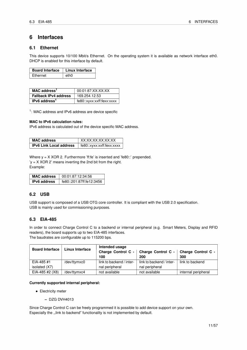
This device supports 10/100 Mbit/s Ethernet. On the operating system it is available as network interface eth0.DHCP is enabled for this interface by default.
Board Interface Linux InterfaceEthernet eth0
MAC address1 00:01:87:XX:XX:XXFallback IPv4 address 169.254.12.53IPv6 address1 fe80::xyxx:xxff:fexx:xxxx
1: MAC address and IPv6 address are device specific
MAC to IPv6 calculation rules:IPv6 address is calculated out of the device specific MAC address.
MAC address XX:XX:XX:XX:XX:XXIPv6 Link Local address fe80::xyxx:xxff:fexx:xxxx
Where y = X XOR 2. Furthermore ’ff:fe’ is inserted and ’fe80::’ prepended.’y = X XOR 2’ means inverting the 2nd bit from the right.Example:
MAC address 00:01:87:12:34:56IPv6 address fe80::201:87ff:fe12:3456
6.2 USB
USB support is composed of a USB OTG core controller. It is compliant with the USB 2.0 specification.USB is mainly used for commissioning purposes.
6.3 EIA-485
In order to connect Charge Control C to a backend or internal peripheral (e.g. Smart Meters, Display and RFIDreaders), the board supports up to two EIA-485 interfaces.The baudrates are configurable up to 115200 bps.
Board Interface Linux InterfaceIntended usageCharge Control C -100
Charge Control C -200
Charge Control C -300
EIA-485 #1isolated (X7)
/dev/ttymxc0 link to backend / inter-nal peripheral
link to backend / inter-nal peripheral
link to backend
EIA-485 #2 (X8) /dev/ttymxc4 not available not available internal peripheral
Currently supported internal peripheral:
• Electricity meter
– DZG DVH4013
Since Charge Control C can be freely programmed it is possible to add device support on your own.Especially the ,,link to backend” functionality is not implemented by default.
11/57

6.6 1-Wire 6 INTERFACES
6.3.1 Start-up behavior
During start there could be a single scan of the Modbus address range 01 - 99 by the metering daemon. In worstcase this takes up to nearly 60 seconds.While the scan is active no access to RS485 bus is possible.
6.3.2 Periodic behavior
The RS485 bus is accessed mutually by the daemons like meteringd.
6.3.3 Error behavior
• in case no meter was found during scan no further scan attempt is made
• the metering daemon is safe against temporary disconnects
6.3.4 Assumptions
All RS485 devices must be connected before powering the charging station.
6.3.5 Adivces for customer applications
Any access to the RS485 device must be protected by TIOCEXCL/TIOCNXCL ioctl calls and should be limited to ashort time (<1 s).All daemons accessing the RS485 must be running as user daemon and group dialout.
6.4 Mains PLC
This device supports 10 Mbit/s HomePlug Green PHYTM power line communication on mains. This interface isavailable on eth2.
Board Interface Linux InterfaceMains PLC eth2
6.5 Control Pilot / Proximity Pilot
For ISO 15118 / DIN 70121 compliant communication between EVSE and PEV Charge Control C supports CP (con-trol pilot) and PP (proximity pilot) signaling including Green PHY communication. This Green PHY communicationis available on interface eth1.
Board Interface Linux InterfaceControl Pilot PLC eth1
6.6 1-Wire
This is a generic 1-Wire interface. It is realised with an I2C to 1-wire bridge. The bridge is handled by DS24841-Wire linux driver and provides the interface /sys/bus/w1/.’Application Note 7 - Charge Control C - Thermal Management’ shows an example how to use the 1-Wire bridge.Since Charge Control C can be freely programmed, it is possible to add device support on your own.
Board Interface Linux Interface1-Wire /sys/bus/w1/
12/57

6.7 Digital Input & Output 6 INTERFACES
6.7 Digital Input & Output
6.7.1 Digital Input
Charge Control C supports up to six digital inputs.All digital inputs have one common adjustable reference level from 0 V till +12 V.The reference voltage can be set trough setting period and duty cycle of a PWM in nano seconds [ns].While a 100% duty cycle corresponds to around 12 V reference voltage.
The required duty cycle to a given period time and reference voltage can be calculated with the following formula:
tdutycycle[ns] = Ureverence[V ]12V ∗ tperiod [ns]
E.g. reference voltage should be 6 V while reference voltage generator is driven with a 25 kHz PWM signal:duty cycle = 6 V * (1 / 25000 Hz * 10ˆ9) / 12 V = 20000 nsVice versa the set reference voltage can be calculated:
Ureverence[V ] =tdutycycle[ns]tperiod [ns] ∗12V
Board Interface Linux Interface Preconfigured function PolarityDIG IN 1 /sys/class/gpio/gpio121 emergency switch active highDIG IN 2 /sys/class/gpio/gpio122 RCD feedback active highDIG IN 3 /sys/class/gpio/gpio124 authorization key switch active highDIG IN 4 /sys/class/gpio/gpio123DIG IN 5 /sys/class/gpio/gpio116DIG IN 6 /sys/class/gpio/gpio119
Board Interface Linux Interfacereference voltage duty cycle /sys/class/pwm/pwmchip1/pwm0/duty cyclereference voltage period time /sys/class/pwm/pwmchip1/pwm0/period
6.7.2 Digital Output
Charge Control C supports up to six digital outputs.
The digital outputs are real push-pull drivers and up to 100 mA can be drawn from a single output.
Board Interface Linux Interface Preconfigured function PolarityPUSH PULL OUT 1 /sys/class/gpio/gpio84 status LED active highPUSH PULL OUT 2 /sys/class/gpio/gpio85PUSH PULL OUT 3 /sys/class/gpio/gpio86PUSH PULL OUT 4 /sys/class/gpio/gpio87PUSH PULL OUT 5 /sys/class/gpio/gpio88PUSH PULL OUT 6 /sys/class/gpio/gpio89
LED charging behavior:
• solid high = ready
• 1000 ms high, 1000 ms low = charging
• 100 ms high, 100 ms low = error
13/57

7.1 X1 - mains 7 BOARD CONNECTIONS
7 Board Connections
Charge Control C has 14 connectors (X1...X14) and three pinheaders (JP1...JP3) as shown in Figure 4.The pinheaders are for configuring (JP1), debugging (JP2) and expanding (JP3) purposes.The connectors are used to establish the connection to the external EVSE periphery.
X12X13X14 X10 X9X11
X4 X5X3X2X1 X7 X8X6
JP2JP1
JP3
Figure 4: Charge Control C Connectors
Please refer to according section of the datasheet for electrical input and output values.
7.1 X1 - mains
The connector is used to connect the mains voltage to it. It provides a filtered mains output.Connecting the AC/DC-power-supply to this output port helps improving PLC signal integrity while using noisy powersupplies.Up to 250 mA can be drawn from this port.
Pin# Signal Note1 L FILTERED filtered mains output L2 N FILTERED filtered mains output N3 L mains input L4 N mains input N5 PE protective earth, also board GND reference level
14/57

7.6 X6 - Ethernet - USB 7 BOARD CONNECTIONS
7.2 X2 - DC in
This product needs DC supply voltage input.
Pin# Name1 +12V2 GND
7.3 X3 - fan
Charge Control C provides an output for 4-Wire pulse width modulation (PWM) controlled fans.
Pin# Signal1 CONTROL2 SENSE3 +12V4 GND
ATTENTION: most fans have a pullup on the tach signal resulting in signals exceeding the absolute maximum ratingof the fan interface. This could potentially destroy the whole device.
7.4 X4 - 1-Wire
This Product provides a 1-Wire master interface where 1-Wire downstream slave devices (such as temperaturesensors) can be connected.
Pin# Signal1 1W IO2 GND
7.5 X5 - Control and Proximity pilot
The connector is used for connecting to EV. It provides the signals for control pilot, proximity pilot as well as Green-PHY powerline communication.
Pin# Signal1 Control pilot2 Proximity pilot
7.6 X6 - Ethernet - USB
X6 is a stacked Ethernet and USB connector.
7.6.1 Ethernet
The Ethernet port supports 10/100 MBit/s and has embedded link and activity LED indicators.
7.6.2 USB
Charge Control C usually acts as USB host at this port. Up to 500 mA can be drawn from this port. It also can beused for provisioning purposes.
15/57

7.9 X9 / X10 - locking motor 7 BOARD CONNECTIONS
7.7 X7 - EIA-485 1/2
The first EIA-485 (RS485) of Charge Control C is a galvanically isolated one.
Pin# Signal1 B2 A3 REF
7.8 X8 - EIA-485 2/2 - CAN
This connector is used to connect to the i.MX6ULL using CAN or EIA-485 (RS485). Both interfaces are referencedto GND. The selection is set via assembly options of the board. Please see ordering informations to select theappropriate variant.
Pin#SignalCAN RS485
1 H B2 L A3 GND
7.9 X9 / X10 - locking motor
X9 and X10 have the same pinout.
Pin# Signal1 OUT22 OUT13 SENSE4 GND
Only X9 supports motor lock failsafe opening in the case of power loss.
There are locking motors available with different internal feedback circuity. Attach them according to the followingimages.
X9 / X10
1
2
3
4
M
Figure 5: Typical Kuster and Phoenix Motor
16/57

7.10 X11 - digital in 7 BOARD CONNECTIONS
X9 / X10
1
2
3
4
M
RS
RP
Figure 6: Typical Kuster Motor, Rs=1kΩ, Rp=10kΩ
X9 / X10
1
2
3
4
M
Figure 7: Typical Hella, Bals, Mennekes & Walther Werke Motor
7.10 X11 - digital in
This port supports digital inputs with digital adjustable reference level of up to +12 V.
Pin# Signal1 DIG IN 12 DIG IN 23 DIG IN 34 DIG IN 45 GND
17/57

7.15 JP2 - debug UART 7 BOARD CONNECTIONS
7.11 X12 - digital in and out
This port supports two digital inputs with digital adjustable reference level of up to +12 V and two digital outputs.The outputs are real push-pull drivers and up to 100 mA can be drawn from a single output.
Pin# Signal1 DIG IN 52 DIG IN 63 PUSH PULL OUT 64 PUSH PULL OUT 5
7.12 X13 - digital out
This port supports digital outputs with real push-pull drivers. Up to 100 mA can be drawn from a single output.
Pin# Signal1 PUSH PULL OUT 42 PUSH PULL OUT 33 PUSH PULL OUT 24 PUSH PULL OUT 15 GND
7.13 X14 - relays
Two normally open (NO) relays are populated on Charge Control C. They are able to handle mains voltage level.One sense input for every switched load is supported.
Pin# Signal Description1 COM L mains L input2 NO 1 relay #1 switched L output3 SENSE 1 relay #1 sense input4 NO 2 relay #2 switched L output5 SENSE 2 relay #2 sense input
Both sense inputs need reference to Neutral (N). Leave it open for ,,inactive” feedback and tie it to Neutral (N) for,,active” feedback.
7.14 JP1 - bootmode jumper
Jumper Position Bootmode1-2 USB serial downloader2-3, or removed eMMC internal boot
7.15 JP2 - debug UART
JP1 Pin Signal1 GND2 not connected3 not connected4 RX of i.MX6ULL5 TX of i.MX6ULL6 not connected
18/57

7.16 JP3 - expansion port 7 BOARD CONNECTIONS
This pinout is compatible with a variety of USB/RS232 adapters. Preferable you should use the FTDI cable,,TTL-232R-3V3” or similar, do not use long wires to connect the debug UART.
ATTENTION: Do not use generic RS232 adapters, as they usually have +-12 V voltages for their logic signals. Thepins here are only 3.3 V tolerant. You may damage the debug UART with incompatible adapters.
Use the following settings to connect to the debug UART:
Setting ValueBaud Rate 115200Data bits 8Stop bits 1Parity NoneFlow control None
7.16 JP3 - expansion port
JP3 is a connector for additional I2SE expansion boards.
19/57

8 USE CASES
8 Use cases
In the following sections typical use cases for the Charge Control C family are shown.Signals and components drawn with light gray color are optional signals and components and are not required forsuccessful charging behavior.
8.1 IEC 61851 AC charging
A basic AC charging station including IEC 61851 conform proximity detection, control pilot function and PWMcharging signal can be built up with every member of the Charge Control C family.Different kinds of IEC 61851 compliant charging stations are shown below.
8.1.1 One phase charging
A typical Charge Control C - 100 based EV charging station is shown by Figure 8 and consists of:
• Charge Control C - 100
• 12 V - AC/DC converter
• Type-2 cable
• Mains contactor
• RCD Type B with feedback signal
• Status LED
• Circuit breaker
• Emergency switch
20/57

8.1IE
C61851
AC
charging8
US
EC
AS
ES
Type-2 Cable
CP PP
L1
L3 L2
PEN
Charge Control C - 100
L1 N PE
Emergency
switch
Mains
contactor
Power switch
(Circuit breaker, 6 A)
N
12 VGND
ACDC
RCD
and
d.c. fault
current
protection
Status
LED
Charging Station
X13-5 GNDX13-4 digital out 1X13-3 digital out 2X13-2 digital out 3X13-1 digital out 4
X2-1 DC supply in +12VX2-2 DC supply in GND
X1-1 L filtered out
X1-2 N filtered out
X1-3 L in
X1-4 N in
X1-5 PE
X11-5 GNDX11-4 digital in 4X11-3 digital in 3X11-2 digital in 2X11-1 digital in 1
X5-1 control pilot & PLCX5-2 proximity pilot
X7-1 RS485 1 BX7-2 RS485 1 AX7-3 GND
X6USB
X14-3 relay 1 sense
X14-2 relay 1 NO L
X14-1 relay COM L
L
RCD-Type B
Figure 8: Use case Charge Control C - 100 - 1 Phase Charging
21/57

8.1IE
C61851
AC
charging8
US
EC
AS
ES
8.1.2 Three phase charging
Also the realisation of 3 phase EV charging stations are possible with all variants of Charge Control C. Figure 9 shows Figure 8 but in 3 phase configuration.
Type-2 Cable
CP PP
L1
L3 L2
PEN
Charge Control C - 100
L3L2L1 N PE
Emergency
switch
Mains
contactor
Power switch
(Circuit breaker, 6 A)
N
12 VGND
ACDC
RCD
and
d.c. fault
current
protection
Status
LED
Charging Station
X13-5 GNDX13-4 digital out 1X13-3 digital out 2X13-2 digital out 3X13-1 digital out 4
X2-1 DC supply in +12VX2-2 DC supply in GND
X1-1 L filtered out
X1-2 N filtered out
X1-3 L in
X1-4 N in
X1-5 PE
X11-5 GNDX11-4 digital in 4X11-3 digital in 3X11-2 digital in 2X11-1 digital in 1
X5-1 control pilot & PLCX5-2 proximity pilot
X7-1 RS485 1 BX7-2 RS485 1 AX7-3 GND
X6USB
X14-3 relay 1 sense
X14-2 relay 1 NO L
X14-1 relay COM L
L
RCD-Type B
Figure 9: Use case Charge Control C - 100 - 3 Phase Charging
22/57

8.2 ISO 15118 AC charging 8 USE CASES
8.2 ISO 15118 AC charging
AC charging stations with ISO 15118 control and proximity pilot signals as well as the PWM charging signal, conformto IEC 61851, can be built up with Charge Control C 200/300.Different kind of ISO 15118 compliant charging station are shown below.
8.2.1 Type-2 cable connection
A typical Charge Control C - 200 based EV charging station is shown by Figure 10 and consists of:
• Charge Control C - 200
• 12 V - AC/DC converter
• Type-2 cable
• Mains contactor
• RCD Type B with feedback signal
• Status LED
• Circuit breaker
• Emergency switch
• Ventilation for the charging area
• Smart meter (RS485)
• Temperature sensors (1-Wire)
• RFID reader (RS485)
• Display (RS485)
• Backend (Connected via Ethernet)
23/57

8.2IS
O15118
AC
charging8
US
EC
AS
ES
Type-2 Cable
CP PP
L1
L3 L2
PEN
Charge Control C - 100
L1 N PE
Emergency
switch
Mains
contactor
Charge Control C - 200
to backend
Ventilation (charging area)
Temperature sensor(s)
Ventilation
contactor
...
Ethernet
X14-5 relay 2 sense
X14-4 relay 2 NO L
X4-1 1-WireX4-2 GND
X10-4 GNDX10-3 motor 2 senseX10-2 motor 2 out 1X10⁻¹ motor 2 out 2
X9-4 GNDX9-3 motor 1 senseX9-2 motor 1 out 1X9-1 motor 1 out 2
Smart
meter
RFIDreader
Display
L N PE
Power switch
(Circuit breaker, 6 A)
N
12 VGND
ACDC
RCD
and
d.c. fault
current
protection
Status
LED
Charging Station
X13-5 GNDX13-4 digital out 1X13-3 digital out 2X13-2 digital out 3X13-1 digital out 4
X2-1 DC supply in +12VX2-2 DC supply in GND
X1-1 L filtered out
X1-2 N filtered out
X1-3 L in
X1-4 N in
X1-5 PE
X11-5 GNDX11-4 digital in 4X11-3 digital in 3X11-2 digital in 2X11-1 digital in 1
X5-1 control pilot & PLCX5-2 proximity pilot
X7-1 RS485 1 BX7-2 RS485 1 AX7-3 GND
X6USB
X14-3 relay 1 sense
X14-2 relay 1 NO L
X14-1 relay COM L
L
RCD-Type B
Figure 10: Use case Charge Control C - 200 - with fixed charging cable
24/57

8.2IS
O15118
AC
charging8
US
EC
AS
ES
8.2.2 Type-2 inlet connection
Charge Control C is capable of driving Type-2 Inlet locking motors. So it is possible to build charging stations with Type-2 inlet instead of fixed Type-2 cable.Figure 11 shows Figure 10-configuration but with Type-2 inlet and interlock instead of fixed Type-2 cable.
Type-2 Cable
CP PP
L1
L3 L2
PEN
Charge Control C - 100
L1 N PE
Emergency
switch
Mains
contactor
External lid interlock
of the Type-2 Inlet
Interlock for
Type-2 Inlet*
M
Type-2 Inlet
Charge Control C - 200
to backend
Ventilation (charging area)
Temperature sensor(s)
Ventilation
contactor
...
Ethernet
X14-5 relay 2 sense
X14-4 relay 2 NO L
X4-1 1-WireX4-2 GND
X10-4 GNDX10-3 motor 2 senseX10-2 motor 2 out 1X10⁻¹ motor 2 out 2
X9-4 GNDX9-3 motor 1 senseX9-2 motor 1 out 1X9-1 motor 1 out 2
Smart
meter
RFIDreader
Display
L N PE
Power switch
(Circuit breaker, 6 A)
N
12 VGND
ACDC
RCD
and
d.c. fault
current
protection
Status
LED
Charging Station
X13-5 GNDX13-4 digital out 1X13-3 digital out 2X13-2 digital out 3X13-1 digital out 4
X2-1 DC supply in +12VX2-2 DC supply in GND
X1-1 L filtered out
X1-2 N filtered out
X1-3 L in
X1-4 N in
X1-5 PE
X11-5 GNDX11-4 digital in 4X11-3 digital in 3X11-2 digital in 2X11-1 digital in 1
X5-1 control pilot & PLCX5-2 proximity pilot
X7-1 RS485 1 BX7-2 RS485 1 AX7-3 GND
X6USB
X14-3 relay 1 sense
X14-2 relay 1 NO L
X14-1 relay COM L
L
RCD-Type B
Figure 11: Use case Charge Control C - 200 - with pluggable charging cable
25/57

8.2 ISO 15118 AC charging 8 USE CASES
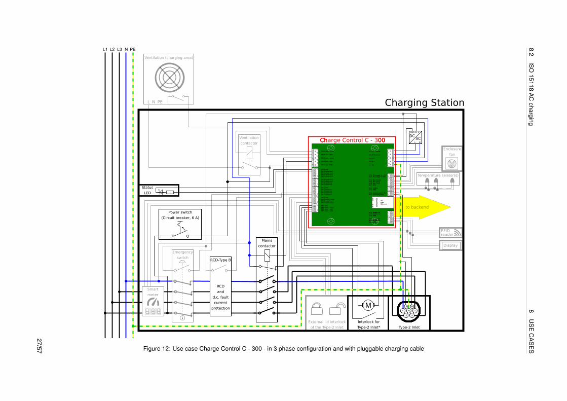
8.2.3 Three phase charging
Only Charge Control C - 300 supports the full set of available connectors.A typical Charge Control C - 300 based EV charging station consists of:
• Charge Control C - 300
• 12 V - AC/DC converter
• Type-2 cable
• Mains contactor
• RCD Type B with feedback signal
• Status LED
• Circuit breaker
• Emergency switch
• Ventilation for the charging area
• RS485 devices (Smart meter, RFID reader, Display) distributed over two separate RS485 interfaces
• Temperature sensors (1-Wire)
• Backend (Connected via Ethernet)
• Enclosure ventilation
• supports more Input and Output ports for additional I/O-devices
26/57
8.2IS
O15118
AC
charging8
US
EC
AS
ES
Type-2 Cable
CP PP
L1
L3 L2
PEN
Charge Control C - 100
L3L2L1 N PE
Emergency
switch
Mains
contactor
External lid interlock
of the Type-2 Inlet
Interlock for
Type-2 Inlet*
M
Type-2 Inlet
Charge Control C - 200
to backend
Enclosure
fan
Charge Control C - 300
X12-4 digital out 5X12-3 digital out 6X12-2 digital in 6X12-1 digital in 5
X3-1 fan controlX3-2 fan senseX3-3 fan +12 VX3-4 GND
X8-1 RS485 2 BX8-2 RS485 2 AX8-3 GND
to backend
Ventilation (charging area)
Temperature sensor(s)
Ventilation
contactor
...
Ethernet
X14-5 relay 2 sense
X14-4 relay 2 NO L
X4-1 1-WireX4-2 GND
X10-4 GNDX10-3 motor 2 senseX10-2 motor 2 out 1X10⁻¹ motor 2 out 2
X9-4 GNDX9-3 motor 1 senseX9-2 motor 1 out 1X9-1 motor 1 out 2
Smart
meter
RFIDreader
Display
L N PE
Power switch
(Circuit breaker, 6 A)
N
12 VGND
ACDC
RCD
and
d.c. fault
current
protection
Status
LED
Charging Station
X13-5 GNDX13-4 digital out 1X13-3 digital out 2X13-2 digital out 3X13-1 digital out 4
X2-1 DC supply in +12VX2-2 DC supply in GND
X1-1 L filtered out
X1-2 N filtered out
X1-3 L in
X1-4 N in
X1-5 PE
X11-5 GNDX11-4 digital in 4X11-3 digital in 3X11-2 digital in 2X11-1 digital in 1
X5-1 control pilot & PLCX5-2 proximity pilot
X7-1 RS485 1 BX7-2 RS485 1 AX7-3 GND
X6USB
X14-3 relay 1 sense
X14-2 relay 1 NO L
X14-1 relay COM L
L
RCD-Type B
Figure 12: Use case Charge Control C - 300 - in 3 phase configuration and with pluggable charging cable
27/57

9 PROGRAMMING
9 Programming
Charge Control C ships with preflashed firmware including the Charge Control charging stack. However, it ispossible for customers to add new programs and customer software and/or modify none-charging stack config-uration files. To allow rapid prototyping on the boards itself, the shipped firmware includes a preinstalled C/C++compiler and several commonly used libraries for onboard development. So it is possible to login via SSH, transfercustomers software sources to the board and then compile this software on the board. Since the Charge Control Cfirmware is based on standard Debian distribution, there should be no significant difference compared to compilingsuch software on a usual PC Linux environment - except missing graphical development tools and reduced speeddue to the embedded CPU performance. It highly depends on customer software and its dependencies whetherthis approach gives a good developer experience. But once the customer software is compiled, it can be transferredand installed on other boards.
Another approach is to cross-compile customer firmware. For this a working cross-compiler is required on thecustomers PC Linux environment, recent Linux distributions include cross-compilers via their package managementsystem (e.g. Ubuntu: crossbuild-essential-armhf etc.). Then a copy of the target root filesystem is requiredwhich includes target headers, target libraries etc. This root filesystem can be created using I2SE’s STIB (seehttps://github.com/I2SE/stib/), see STIB documentation for detailed instructions. Also ensure that you usethe matching branch for your product.After having setup such a root filesystem, it’s possible to add tools libraries, scripts etc. which are required bycustomer software. Customers are expected to have experience in cross development.
I2SE recommendation for custom software development is:
• Develop your customer software on your local PC Linux environment. Here you can use compiler, debuggeretc. you are familiar with. Since I2SE Charge Control stack’s API is provided via MQTT, you can simply setupone ,,developer” Charge Control C device and access the stack’s API via Ethernet network. If everythingworks as expected in this setup, then switch to cross-compiling and/or compiling natively on the target system.
• Use autotools or cmake and pkg-config in your customer software projects as build environment. Prefer suchmature and proven tools since these are widely supported and understood and cross-compiling with thesetools is usually easy.
• When starting your project from scratch, have a look at libraries which are already required by Charging Stackand/or Linux distribution. Re-use these libraries to keep the overall firmware footprint small. The benefit iswhen updating the boards it will take less time when transfering the firmware update image and flashing it tointernal storage.
28/57

11 CHARGING STACK INITIALISATION
10 Firmware Upgrade
10.1 via USB
Preparation of the USB-Update
• Download the Firmware Update Image file on your working station (file size is about 284 MB)
• Plug in a USB flash drive in your working station
• Format the USB flash drive as EXT2/3/4, FAT16/32, NTFS
• Copy the Firmware Update Image file (*.image) onto the USB flash drive root directoryNote: Don’t place multiple *.image files for Charge Control C on the USB flash drive since it’s not guaranteedin which order the files are tried and applied.
Updating the Charge Control C Firmware
• Connect the board to the power supply and wait until the board is booted
• Connect to the board via SSH or Debug UART to backup all your own implementation and configuration files
• Plug in the USB flash drive with the Firmware Update Image file in the USB port of the board
• Observe the LED update indications:
– If the USB is plugged the yellow LED (LED1 of the board) is turned on statically
– If the updated process has started the yellow LED is blinking (250ms on/250ms off)
– In case no update file was compatible, the yellow LED is turned off
– If the firmware update was successful, the device was rebooted and LED is now turned off
– After the device is rebooted, the USB flash drive is detected again and thus the yellow LED is alsoturned on again.
– But now the new firmware notices that the firmware update is already installed and the yellow LED willbe turned off again (this will take some time).
• Wait until the whole firmware update and reboot process is finished - it takes about 15 minutes.
• When the firmware update process is finished and the yellow LED is turned off again, the USB flash drive canbe plugged out.
10.2 via OCPP
A firmware update via OCPP will be supported with a future update, with introducing support for the OCPP FirmwareManagement Profile.
11 Charging Stack Initialisation
The Charging Stack initializes itself after device boot.Service files for the stack daemons are located in:
/ l i b / systemd / system / ∗ . se rv i ce
and are referenced with symlinks from:
/ e tc / systemd / system / mu l t i−user . t a r g e t . wants /
29/57

12.2 SSH 12 DEVICE ACCESS
12 Device Access
There are different possibilities to access the device for configuration purposes.The username- password combination required for login is:
Username Passwordroot zebematado
This is a generic password so it is required to be changed by the customer!
12.1 Debug UART
JP1 Pin Signal1 GND2 not connected3 not connected4 RX of i.MX6ULL5 TX of i.MX6ULL6 not connected
This pinout is compatible with a variety of USB/RS232 adapters. Preferable you should use the FTDI cable,,TTL-232R-3V3” or similar, do not use long wires to connect the debug UART.
ATTENTION: Do not use generic RS232 adapters, as they usually have ± 12 V voltages for their logic signals. Thepins here are only 3.3 V tolerant. You may damage the debug UART with incompatible adapters.
Use the following settings to connect to the debug UART:
Setting ValueBaud Rate 115200Data bits 8Stop bits 1Parity NoneFlow control None
12.2 SSH
Charge Control C ships with SSH (Secure Shell) service running on Ethernet and mains powerline interface (onlyCharge Control 300). It allows you to connect to Charge Control C securely and perform Linux command-lineoperations. The SSH service is listening on the well-known port number for SSH: TCP port 22.
12.3 Website
Charge Control C is running a web server to provide a web frontend to configure the device and control variousaspects of the charging stack. The web server is listening on the standard TCP Port 80. The web frontend canbe accessed via the Ethernet interface and/or mains powerline interface (only Charge Control 300). To access it,simply put the device’s IPv4 or IPv6 address into your browser’s address bar.Since the Charge Control C devices ship with DHCP enabled, you might need to access your router’s web frontendfirst to determine the IP address given to your Charge Control C board.
30/57

13.1 Charging Stack Configuration Files 13 CONFIGURATION
13 Configuration
I2SE’s charging stack is built as an application on top of a Linux system. Several software components interact witheach other and rely on various configuration files.The ,,Charge Control” configuration files are described in the following section. Devices ship with a defaultconfiguration as shown in Table 35 and Table 37. Several configuration files which are present on regular Debiansystems also influence stack behaviour.
I2SE is not liable for a standard compliant charger configuration.’Application Note 9 - Charge Control C - Digital Input/Output configuration’ gives an detailed overview about how toconfigure digital input and output of the product.
13.1 Charging Stack Configuration Files
configuration file description preserved during update/etc/secc/customer.json defines most of the charging stack behavior yes/etc/secc/leds.json defines the LED behavior for the digital outputs yes/etc/secc/rotaryencd.json defines the rotary encoder switch meaning yes
• These JSON files use comments to describe the keys’ functions and their possible values. (Comments are anon-standard extension to JSON.)
• Please ensure that, when editing these files, correct JSON syntax (plus the comments) is adhered to.
31/57

13.1C
hargingS
tackC
onfigurationFiles
13C
ON
FIGU
RATIO
N
hardware configuration (found in /etc/secc/customer.json)parameter description type defaultchargeports[0]/pluggable whether a charging cable is at-
tached to the EVSE with a plug intoa socket
Boolean(true = socket, false = fixed cable)
true
chargeports[0]/proximity pilot/cable current limit current limit in Ampere of a fixed ca-ble (per phase)
Integer 10
chargeports[0]/proximity pilot/phase count number of phases Integer ( 1 or 3 ) 1chargeports[0]/contactor/feedback type defines the logic behind the contac-
tor feedback (Relay 1)String (,,nc” = normally close,,,no” = normally open)
,,nc”
chargeports[0]/ventilation/enable enables external ventilation control(Relay 2)
Boolean false
chargeports[0]/emergency alarm/enable enables emergency alarm monitor-ing
Boolean false
chargeports[0]/emergency alarm/gpio defines GPIO line connected toemergency contact
Integer 121
chargeports[0]/plug lock/type selects the plug lock motor type String(,,KUESTER-02S”,,,KUESTER-04S”,,,EV-T2M3S-E-LOCK12V”,,,HELLA-MICRO-ACTUATOR-1”,,,WALTHER-WERKE-9798999009”)
,,EV-T2M3S-E-LOCK12V”
chargeports[0]/meter/enable enables metering support Boolean truechargeports[0]/meter/port defines UART interface to the meter String ”/dev/ttymxc0”chargeports[0]/meter/protocol specifies the meter’s Modbus proto-
colString (,,dzg”) ,,dzg”
chargeports[0]/meter/baudrate baudrate of Modbus protocol Integer 9600chargeports[0]/meter/parity parity of Modbus protocol String ( ,,none”, ,,odd”, ,,even” ) ,,none”chargeports[0]/power electronic config/nominal voltage specifies the nominal voltage of the
grid in V (one phase to neutral)Integer 230
Table 35: Configuration Hardware Parameter customer.json
32/57

13.1C
hargingS
tackC
onfigurationFiles
13C
ON
FIGU
RATIO
N
software configuration (found in /etc/secc/customer.json)parameter description type defaultchargeports[0]/always accept cp state d indicates whether an EV which
requests CP state D (ventilation)should always be accepted
boolean false
chargeports[0]/free charging indicates whether the charging ses-sion needs to be authenticated
boolean true
chargeports[0]/highlevel authentication mode specifies the authentication modefor the high level charging session
String(,,eim”)
,,eim”
chargeports[0]/tls security controls how to handle encryptedcommunication during high levelcharging
String(,,prohibit”,,,allow”, ,,force”)
,,prohibit”
chargeports[0]/evse id provides the EVSEID of the actualcharger.
String[37] ,,DE*I2S*E123456789012345678901234567890”
chargeports[0]/meter/publish settings/timer defines the MQTT publish interval ofmetering data in seconds
Integer 30
ocpp/enable enable OCPP client Boolean falseocpp/uri identifies the charge point specific
URI of the backend’s WebSocketservice (must begin with lowercasews:// or wss://)
String
ocpp/verify cert whether to verify the Secure Web-Socket server’s TLS certificate (onlyvalid for secure connections, notrecommended to disable)
Boolean true
ocpp/charge point model identifies the model of the ChargePoint
String[20]
ocpp/charge point vendor identifies the vendor of the ChargePoint
String[20]
ocpp/charge point serialnumber identifies the serial number of theCharge Point
String[25]
Table 37: Configuration Software Parameter customer.json
33/57

13.1C
hargingS
tackC
onfigurationFiles
13C
ON
FIGU
RATIO
N
hardware configuration (found in /etc/secc/leds.json)parameter description type defaultleds[0]/gpios defines the digital output GPIOs which are con-
nected to the LEDs (1st for red, 2nd for green, 3rdfor blue)
Array of Integer [3] [84]
software configurationleds[0]/behaviors[]/condition specifies under which condition this behavior takes
effectString(,,init”, ,,updating”, ,,auth pending”, ,,auth accepted”, ,,auth rejected”,,,ready”, ,,reserved”, ,,connected”, ,,charge request”, ,,ventila-tion request”, ,,charge 1”,”ventilation 1”, ,,error”)
leds[0]/behaviors[]/mode specifies the LED mode of this behavior ( blink fast= 100 ms on / 100 ms off, blink slow = 1 s on / 1 soff)
String(,,solid”, ,,blink slow”, ,,blink fast”)
leds[0]/behaviors[]/color specifies the LED color of this behavior ( black =off )
String(,,black”, ,,white”, ,,red”, ,,green”, ,,blue”, ,,cyan”, ,,yellow”, ,,magenta”)
leds[0]/behaviors[]/duration specifies the duration of this behavior in 1/100 ms( 0 = permanent )
Integer 0
Table 39: Configuration Parameter leds.json
configuration (found in /etc/secc/rotaryencd.json)parameter description typerotary switch 1[0]/phase count defines the phase count for setting 0 on rotary switch SW2 Integer (1 , 3)rotary switch 1[0]/current limit defines the grid current limit in Ampere for setting 0 on rotary switch SW2 Integer (1 .. 10000)rotary switch 1[1]/phase count defines the phase count for setting 1 on rotary switch SW2 Integer (1 , 3)rotary switch 1[1]/current limit defines the grid current limit in Ampere for setting 1 on rotary switch SW2 Integer (1 .. 10000)... ... ...rotary switch 1[15]/phase count defines the phase count for setting F on rotary switch SW2 Integer (1 , 3)rotary switch 1[15]/current limit defines the grid current limit in Ampere for setting F on rotary switch SW2 Integer (1 .. 10000)
Table 41: Configuration Parameter rotaryencd.json
34/57

13.2 Debian Linux Configuration 14 MQTT AND MOSQUITTO DOCUMENTATION
13.2 Debian Linux Configuration
13.2.1 Network Configuration
Charge Control C devices ship with DHCP enabled by default on the Ethernet interface eth0 while the mainspowerline network interface eth2 (Charge Control C 300 only) is left unconfigured by default.
The network interface configuration can be changed in /etc/network/interfaces.d/eth0 and/or /etc/network/interfaces.d/eth2. See Debian system configuration handbook for details available e.g. on theInternet.
The Control Pilot interface can also be configured in this way by using /etc/network/interfaces.d/eth0. How-ever, I2SE does not recommend to change the factory settings nor should it be necessary at all to change them.
13.2.2 OCPP Root Certificate Authority Keys/Certficates
OCPP communication with a backend provider might be encrypted using a TLS connection. The backend serviceprovider usually provides configuration details, i.e. whether TLS is required or not. If TLS is required, the OCPPserver presents a X.509 certificate to the device which is signed by a ,,well-known” Root Certificate Authority,or not. Well-known Root Certificate Authority means in this context that its root certificate is known by commonbrowsers. On Debian systems such certificates are packaged in a Debian package called ,,ca-certficates”. ChargeControl’s OCPP implementation uses standard TLS libraries, so the usual (Debian) system-wide Root CertificateAuthority files apply to TLS connections, too.
If the OCPP backend provider does not use such a well-known Root CA, then the Root CA’s certificate file mustbe additionally installed on the device. Such X.509 cetificates must be stored as PEM encoded files with .crtextension in /usr/local/share/ca-certificates. After placing the file(s) at this location, update-ca-certificatesmust be invoked on the device to update the Root CA bundle file, install required symlinks etc. See man page man8 update-ca-certificates and/or Debian package documentation for details.
14 MQTT and mosquitto documentation
In the default configuration it is not necessary to interact with MQTT at all.
14.1 MQTT-Interface and configuration
The I2SE Charging interface uses the MQTT protocol to exchange the charging information between the differentcharge control software clients. The topic customer hlc ac.h defines all topics of the I2SE charging interface. TheMQTT broker is available over the internal and external (Ethernet) interface. To implement an own MQTT client it isnecessary to connect to the MQTT broker.
The default configuration of the MQTT broker is:
• MQTT HOSTNAME: ,,localhost” (internal) or IPv4/IPv6 address of the board (external)
• MQTT PORT: 1883
• MQTT CHARGE PORT: ,,port0”
After establishing a MQTT connection to the local message broker it is possible to subscribe and publish to topicsof the I2SE charging interface. It must be considered that all topics are using a specific charging port. This chargeport must be concatenated with each topic of the I2SE charging interface. For the TOPIC CHARGE INIT STATUStopic for example the full topic string would be ,,port0/ci/charge/init/status”. This charge port is intended to providea server/client concept to control several I2SE charging clients with only one secc server. This charge port allowsto distinguish between these charging clients. The default charging port is ,,port0” and can be changed in thecustomer-configuration (See chapter Basic SECC configuration). The I2SE interface uses QoS level 0 for all MQTTmessages and the published messages don’t need to be retained.
35/57

14.2 Charge status information 14 MQTT AND MOSQUITTO DOCUMENTATION
Most of the MQTT message content is defined as ,,SimpleType” and will/must be published as a simplestring-encoded number. For example the content of topic TOPIC EVSE INIT SESSIONID can be published as,,1234567890”. MQTT messages with content type ,,ComplexType” are using JSON objects. In chapter Physicalvalue type is an example for a complex type definition.
The next chapter describes the basic architecture of the MQTT I2SE charging interface.
14.2 Charge status information
A charging session consists of consecutive charging phases. This charging phases are represented by the MQTTcharge status topics. The charge status topics can be marked as ,,started” or ,,finished”. After receiving one ofthese topics it is necessary to handle the phase specific charging information. This charging information is basedon bot, content from the EVCC, which is published to the customer interface, and EVSE content, which needs to bepublished to the customer interface. So the first step in each phase is to analyze the received EVCC information andthen react according to the standard, with the help of the EVSE MQTT messages.The name of the MQTT messageindicates which messages need to be handled. The figure below shows the structure of the charge status specifictopics.
Figure 13: Structure of topics
The information type can be ,,EV” or ,,EVSE”. On EVSE side only topics with ,,EVSE” are intended to be publishedto the customer interface. All topics with ,,EV” will be published from the I2SE charging interface. The chargestatus information indicates the current charging phase. The EVSE topic TOPIC EVSE INIT SESSIONID needsto be published after receiving the TOPIC CHARGE INIT STATUS with ,,started” topic. Customers who want todevelop a charger need to subscribe to topics which start with TOPIC CHARGE and TOPIC EV and publish topicswhich start with TOPIC EVSE. Customers who want to develop an EV need to subscribe to topics which start withTOPIC CHARGE and TOPIC EVSE and publish topics which start with TOPIC EV.This status topics represent the following charging phases of ISO 15118 protocol:
1. The initialization phase begins at plug connect till the high level message ServicePaymentSelection.
2. The authentication phase begins at the CertificateInstallation message (ISO 15118-PNC mode only) till theend of the Authentication message.
3. The charge parameter phase lasts as long as the ChargeParameterDiscovery message is exchanged.
4. The charge phase lasts as long as the ChargingStatus message is exchanged. Note: the PowerDeliverymessage before AND after the charge phase is contained here.
The flow chart below shows a normal charging sequence with the charging phases of ISO 15118. In most casesthe ,,finished” flags can be ignored, because the phases will be processed sequential.
36/57

14.2 Charge status information 14 MQTT AND MOSQUITTO DOCUMENTATION
Figure 14: Charge flow
In addition to the phase specific status topics it is possible to observe the current connection status. The topicsTOPIC CHARGE CP STATUS and TOPIC CHARGE PWM STATUS can be used to observe the physical state ofthe CP pin. The combination of both values provides important information about the current connection state. Thetable below shows the possible combinations:
CP State PWM-Status CP State InformationA (12V) 100% A1: EV unpluggedA (12V) 5% A2: EV unplugged with PWMB (9V) 100% B1: EV connectedB (9V) 5% B2: EV connected with high level communicationC (6V) 5% C2: ChargingF (-12V) Unavailability of the charging stationE (0V) Power outage or short of the control pilot to PE
Besides the CP State information, the current TCP status (indicated by topic TOPIC CHARGE TCP STATUS) isanother essential information about the current connection status. After the EVCC uses the SECC DiscoveryProtocol (SDP) to get the IP address and port number of the SECC, the EVCC can establish a TCP connectionto the SECC. The TCP status switches from ’0’ (not connected) to ’1’ (connection established). This is one of thefirst topics after the plug of the EV is connected.TOPIC CHARGE TCP STATUSIn cases of EVCC timer and errorhandling, it is possible that the EV switches to CP State ’B’ and disconnects the TCP connection immediately withina charging session, so the status topics shall be observed throughout the whole charging session.
37/57

14.3 EVSEProcessing 14 MQTT AND MOSQUITTO DOCUMENTATION
14.3 EVSEProcessing
The EVSEProcessing parameter can be used to delay a specific charging phase. The charging phases ,,AUTH”and ,,PARAMETER” use this parameter. The pre-defined default value of this parameter is set to ’1’ (Ongoing) foreach phase. When the processing of the received EVCC data is finished and the charging flow can be continued,this parameter needs to be explicitly set to ’0’ (Finished). If within the customer configuration file (See chapter BasicSECC configuration) the value for ,,free charging” is set to ,,true”, the value for EVSEProcessing of the ,,AUTH”phase is set to ’0’ (Finished) automatically. When the identifaction of the physical limits (like EVSEMaxCurrentLimit)of the EVSE is finished, the value for EVSEProcessing shall be set to ’0’ (finished) for the ,,PARAMETER” phase.To avoid skipping of data, it is recommended to publish the EVSE-Processing with ,,Finished” after providing thelast phase specific parameter.If the values for the physical limits are preconfigured via the customer configuration file (See chapter Basic SECCconfigurationBasic SECC configuration) or the ,,SW2 - Rotary Coded Switch” (See ChargeControl-C document)then the TOPIC EVSE PARAMETER EVSEPROCESSING can be sent right after TOPIC CHARGE INIT STATUSwith value ,,started” was received.
38/57

14.4M
QTT
Topics14
MQ
TTA
ND
MO
SQ
UITTO
DO
CU
ME
NTATIO
N
14.4 MQTT Topics
14.4.1 Topics indicating the actual status of the ongoing charge phase.
Topic Hierarchy Type Value CommentTOPIC CHARGE INIT PROTOCOL ,,ci/charge/init/protocol” SimpleType string Topic which indicates which charge protocol is used in the actual
charge session. The value of this topic will either be ,,ISO15118”or ,,IEC61851”.
TOPIC CHARGE INIT STATUS ,,ci/charge/init/status” SimpleType string Topic which indicates the beginning or the end of the initializa-tion phase of a high level charge compliant to ISO15118. Thisincludes the protocols SLAC, SDP, TCP and V2GTP from mes-sage SupportedAppProtocol until PaymentDetails. The value ofthis topic will either be ,,started” or ,,finished”.
TOPIC CHARGE AUTH STATUS ,,ci/charge/auth/status” SimpleType string Topic which indicates the beginning or the end of the authentica-tion phase of a high level charge compliant to ISO15118. This in-cludes the V2GTP message Cerificate* and Authentication. Thevalue of this topic will either be ,,started” or ,,finished”.
TOPIC CHARGE PARAMETER STATUS ,,ci/charge/parameter/status” SimpleType string Topic which indicates the beginning or the end of the chargeparameter discovery phase of a high level charge compliant toISO15118. This includes the V2GTP message ChargeParame-terDiscovery. The value of this topic will either be ,,started” or,,finished”.
TOPIC CHARGE CHARGE STATUS ,,ci/charge/charge/status” SimpleType string Topic which indicates the beginning or the end of the chargephase of a high level charge compliant to ISO15118. Thisincludes the V2GTP messages PowerDelivery, ChargingStatusand MeteringReceipt. The value of this topic will either be,,started” or ,,finished”.
TOPIC CHARGE BASIC STATUS ,,ci/charge/basic/status” SimpleType string Topic which indicates the beginning or the end of the basic charg-ing phase of a charge compliant to IEC61851. The value of thistopic will either be ,,started” or ,,finished”.
TOPIC CHARGE CP STATUS ,,ci/charge/cp/status” SimpleType string Topic which indicates the actual CP state in V. The value of thistopic will be an enumeration of the possible CP states accordingIEC61851 which are ,,A”, ,,B”, ,,C”, ,,D”, ,,E” or ,,F”.
39/57

14.4M
QTT
Topics14
MQ
TTA
ND
MO
SQ
UITTO
DO
CU
ME
NTATIO
N
TOPIC CHARGE PP STATUS ,,ci/charge/pp/status” SimpleType integer Topic which indicates the actual PP state of the socket. The valueof this topic will be an enumeration of the possible PP states ac-cording IEC61851 which are ,,Unknown” (0), ,,Not Connected”(1), ,,Connected” (2) or ,,Connected but not latched” (3, Plugtype Type1 specific).
TOPIC CHARGE PWM STATUS ,,ci/charge/pwm/status” SimpleType string Topic which indicates the actual PWM duty cycle in %. The valueof this topic will be the actual value between ,,0” and ,,100”%.
TOPIC CHARGE TCP STATUS ,,ci/charge/tcp/status” SimpleType string Topic which indicates the actual status of the TCP connectionbetween an EV and an EVSE. The value of this topic will eitherbe ,,1” if the connection was established and ,,0” otherwise.
TOPIC CHARGE PLUG STATUS ,,ci/charge/plug/status” SimpleType string Topic which indicates the actual status of the Plug lock on cus-tomers side. The value of this topic will either be ,,locked” or,,unlocked” if the lock state can be detected. ,,unknown” whenthe lock state cannot be detected.
TOPIC CHARGE CONTACTOR STATUS ,,ci/charge/contactor/status” SimpleType string Topic which indicates the actual status of the contactor on cus-tomers side. The value of this topic will either be ,,closed” or,,opened” if the contactor state can be detected. ,,unknown”when the contactor state cannot be detected.
14.4.2 EVSE specific v2g parameter of the initialization phase
Topic Hierarchy Type Value CommentTOPIC EVSE INIT SESSIONID ,,ci/evse/init/sessionid” SimpleType long integer Topic which provides the Ses-
sionID of the actual chargingsession. Will be or should bepublished at the very beginningof the high level charge, at leastafter the TCP status changes to,,1”.
TOPIC EVSE INIT EVSEID ,,ci/evse/init/evseid” SimpleType integer Topic which provides the EV-SEID of the actual charger. Willbe or should be published at thevery beginning of the high levelcharge, at least after the TCPstatus changes to ,,1”.40/57

14.4M
QTT
Topics14
MQ
TTA
ND
MO
SQ
UITTO
DO
CU
ME
NTATIO
N
TOPIC EVSE INIT DATETIMENOW ,,ci/evse/init/datetimenow” SimpleType integer Topic which provides the actualdate and time of the charger inmilliseconds from epoch. Willbe or should be published at thevery beginning of the high levelcharge, at least after the TCPstatus changes to ,,1”.
TOPIC EVSE INIT PAYMENTOPTIONS ,,ci/evse/init/paymentoptions” ComplexType paymentOptionJsonObject ,,PaymentOption0”: int,,,PaymentOption1”: int
Topic which provides the pay-ment options of the actualcharger. Will be or should bepublished at the very beginningof the high level charge, at leastafter the TCP status changes to,,1”.
TOPIC EVSE INIT CHARGESERVICE ,,ci/evse/init/chargeservice” ComplexType chargeServiceJsonObject ,,ServiceID”: int,,,ServiceName”:,,Name of the Service”,,,ServiceCategory”: int,,,ServiceScope”:,,Name of the ServiceScope”,,,FreeService”: bool,,,SupportedEnergyTransferType0”: int,,SupportedEnergyTransferType1”: int,,SupportedEnergyTransferType2”: int,,SupportedEnergyTransferType3”: int,,SupportedEnergyTransferType4”: int
Topic which provides the chargeservices of the actual charger.Will be or should be publishedat the very beginning of the highlevel charge, at least after theTCP status changes to ,,1”.
TOPIC EVSE INIT SERVICELIST ,,ci/evse/init/servicelist” ComplexType Topic which provides the addi-tional services of the charger be-side the charge service. Will beor should be published at thevery beginning of the high levelcharge, at least after the TCPstatus changes to ,,1”.
41/57
14.4M
QTT
Topics14
MQ
TTA
ND
MO
SQ
UITTO
DO
CU
ME
NTATIO
N
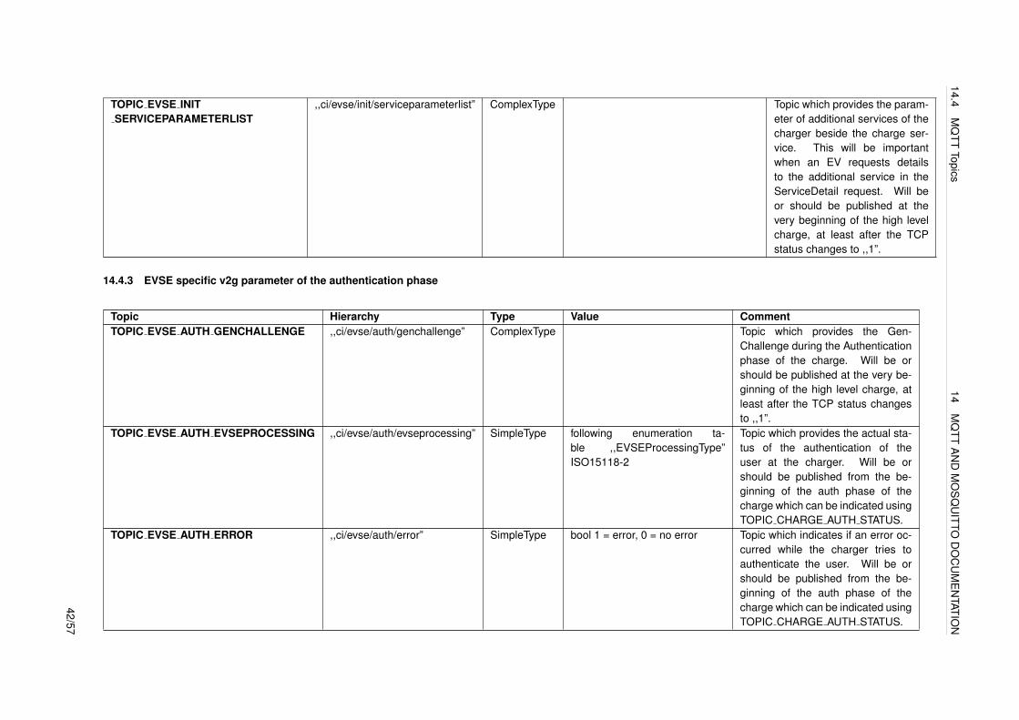
TOPIC EVSE INITSERVICEPARAMETERLIST
,,ci/evse/init/serviceparameterlist” ComplexType Topic which provides the param-eter of additional services of thecharger beside the charge ser-vice. This will be importantwhen an EV requests detailsto the additional service in theServiceDetail request. Will beor should be published at thevery beginning of the high levelcharge, at least after the TCPstatus changes to ,,1”.
14.4.3 EVSE specific v2g parameter of the authentication phase
Topic Hierarchy Type Value CommentTOPIC EVSE AUTH GENCHALLENGE ,,ci/evse/auth/genchallenge” ComplexType Topic which provides the Gen-
Challenge during the Authenticationphase of the charge. Will be orshould be published at the very be-ginning of the high level charge, atleast after the TCP status changesto ,,1”.
TOPIC EVSE AUTH EVSEPROCESSING ,,ci/evse/auth/evseprocessing” SimpleType following enumeration ta-ble ,,EVSEProcessingType”ISO15118-2
Topic which provides the actual sta-tus of the authentication of theuser at the charger. Will be orshould be published from the be-ginning of the auth phase of thecharge which can be indicated usingTOPIC CHARGE AUTH STATUS.
TOPIC EVSE AUTH ERROR ,,ci/evse/auth/error” SimpleType bool 1 = error, 0 = no error Topic which indicates if an error oc-curred while the charger tries toauthenticate the user. Will be orshould be published from the be-ginning of the auth phase of thecharge which can be indicated usingTOPIC CHARGE AUTH STATUS.
42/57

14.4M
QTT
Topics14
MQ
TTA
ND
MO
SQ
UITTO
DO
CU
ME
NTATIO
N
14.4.4 EVSE specific v2g parameter of the parameter discovery phase
Topic Hierarchy Type Value CommentTOPIC EVSE PARAMETER EVSEPROCESSING ,,ci/evse/parameter/
evseprocessing”SimpleType following enumeration
table ,,EVSEProcessing-Type” ISO15118-2
Topic which provides the actual status ofthe parameter discovery of the charger.Will be or should be published from thebeginning of the parameter phase ofthe charge which can be indicated usingTOPIC CHARGE PARAMETER STATUS.
TOPIC EVSE PARAMETER SASCHEDULELIST ,,ci/evse/parameter/saschedulelist”
ComplexType sascheduleListJsonObject: ,,SAScheduleTupleID” :int,,,Start” : [int, ...],,,Duration” : int,,,PMax” : [int, ...],,,PMaxMultiplier” : [int, ...]
Topic which provides the chargingschedule list of the charger. Will beor should be published from the be-ginning of the parameter phase ofthe charge which can be indicated usingTOPIC CHARGE PARAMETER STATUS.
TOPIC EVSE PARAMETER SALESTARIFF ,,ci/evse/parameter/salestariff” ComplexType Topic which provides the SalesTar-iffs of the energy provider. Will beor should be published from the be-ginning of the parameter phase ofthe charge which can be indicated usingTOPIC CHARGE PARAMETER STATUS.
TOPIC EVSE PARAMETER MAXCURRENTLIMIT ,,ci/evse/parameter/maxcurrentlimit”
ComplexType maxCurrentLimitJsonObject ,,Multiplier” : byte,,,Value” : short
Topic which provides the chargers max-imum current limit in the parameterdiscovery phase of the charge. Willbe or should be published from thebeginning of the parameter phase ofthe charge which can be indicated usingTOPIC CHARGE PARAMETER STATUS.
TOPIC EVSE PARAMETERNOTIFICATIONMAXDELAY
,,ci/evse/parameter/notificationmaxdelay”
SimpleType integer Topic which provides the chargers no-tification max delay in the parameterdiscovery phase of the charge. Willbe or should be published from thebeginning of the parameter phase ofthe charge which can be indicated usingTOPIC CHARGE PARAMETER STATUS.
43/57
14.4M
QTT
Topics14
MQ
TTA
ND
MO
SQ
UITTO
DO
CU
ME
NTATIO
N
TOPIC EVSE PARAMETER NOTIFICATION ,,ci/evse/parameter/notification”
SimpleType following enumerationtable ,,EVSENotification-Type” ISO15118-2
Topic which provides the chargersnotification in the parameter discov-ery phase of the charge. Will be orshould be published from the begin-ning of the parameter phase of thecharge which can be indicated usingTOPIC CHARGE PARAMETER STATUS.
TOPIC EVSE PARAMETER NOMINALVOLTAGE ,,ci/evse/parameter/nominalvoltage”
ComplexType nominalVoltageJsonObject ,,Multiplier” : byte,,,Value” : short
Topic which provides the chargersnominal line voltage in the parameterdiscovery phase of the charge. Willbe or should be published from thebeginning of the parameter phase ofthe charge which can be indicated usingTOPIC CHARGE PARAMETER STATUS.
TOPIC EVSE PARAMETER RCD ,,ci/evse/parameter/rcd” SimpleType boolean ,,0” or ,,1” Topic which provides the chargers statusof the Residual Current Device in theparameter discovery phase of the charge.Will be or should be published from thebeginning of the parameter phase ofthe charge which can be indicated usingTOPIC CHARGE PARAMETER STATUS.
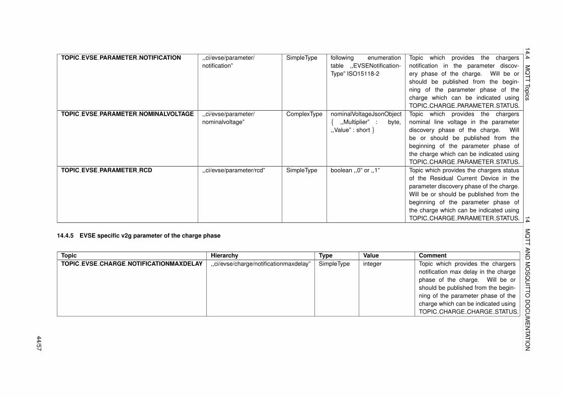
14.4.5 EVSE specific v2g parameter of the charge phase
Topic Hierarchy Type Value CommentTOPIC EVSE CHARGE NOTIFICATIONMAXDELAY ,,ci/evse/charge/notificationmaxdelay” SimpleType integer Topic which provides the chargers
notification max delay in the chargephase of the charge. Will be orshould be published from the begin-ning of the parameter phase of thecharge which can be indicated usingTOPIC CHARGE CHARGE STATUS.
44/57

14.4M
QTT
Topics14
MQ
TTA
ND
MO
SQ
UITTO
DO
CU
ME
NTATIO
N
TOPIC EVSE CHARGE NOTIFICATION ,,ci/evse/charge/notification” SimpleType following enu-meration table,,EVSENoti-ficationType”ISO15118-2
Topic which provides the chargersnotification in the charge phaseof the charge. Will be or shouldbe published from the beginningof the parameter phase of thecharge which can be indicated usingTOPIC CHARGE CHARGE STATUS.
TOPIC EVSE CHARGE METERINFO ,,ci/evse/charge/meterinfo” ComplexType Topic which provides the chargersmeter info in the charge phaseof the charge. Will be or shouldbe published from the beginningof the parameter phase of thecharge which can be indicated usingTOPIC CHARGE CHARGE STATUS.
TOPIC EVSE CHARGE RECEIPTREQUIRED ,,ci/evse/charge/receiptrequired” SimpleType Topic which indicates if the chargerrequires a receipt of the me-ter info in the charge phase ofthe charge. Will be or shouldbe published from the beginningof the parameter phase of thecharge which can be indicated usingTOPIC CHARGE CHARGE STATUS.
14.4.6 EVSE specific details of the basic charging process following IEC61851
Topic Hierarchy Type Value CommentTOPIC EVSE BASIC GRIDCURRENTLIMIT ,,ci/evse/basic/gridcurrentlimit” SimpleType Topic which provides the grid current limit in the basic charg-
ing phase of the charge. Will be or should be published fromthe beginning of the charge phase of the charge which canbe indicated using TOPIC CHARGE BASIC STATUS.
TOPIC EVSE BASIC CHARGECURRENT L1 ,,ci/evse/basic/chargecurrent l1” SimpleType Topic which provides the charge current of L1 in the basiccharging phase of the charge. Will be or should be publishedfrom the beginning of the charge phase of the charge whichcan be indicated using TOPIC CHARGE BASIC STATUS.
45/57

14.4M
QTT
Topics14
MQ
TTA
ND
MO
SQ
UITTO
DO
CU
ME
NTATIO
N
TOPIC EVSE BASIC CHARGECURRENT L2 ,,ci/evse/basic/chargecurrent l2” SimpleType Topic which provides the charge current of L2 in the basiccharging phase of the charge. Will be or should be publishedfrom the beginning of the charge phase of the charge whichcan be indicated using TOPIC CHARGE BASIC STATUS.
TOPIC EVSE BASIC CHARGECURRENT L3 ,,ci/evse/basic/chargecurrent l3” SimpleType Topic which provides the charge current of L3 in the basiccharging phase of the charge. Will be or should be publishedfrom the beginning of the charge phase of the charge whichcan be indicated using TOPIC CHARGE BASIC STATUS.
TOPIC EVSE BASIC CHARGEVOLTAGE L1 ,,ci/evse/basic/chargevoltage l1” SimpleType Topic which provides the charge voltage of L1 in the basiccharging phase of the charge. Will be or should be publishedfrom the beginning of the charge phase of the charge whichcan be indicated using TOPIC CHARGE BASIC STATUS.
TOPIC EVSE BASIC CHARGEVOLTAGE L2 ,,ci/evse/basic/chargevoltage l2” SimpleType Topic which provides the charge voltage of L2 in the basiccharging phase of the charge. Will be or should be publishedfrom the beginning of the charge phase of the charge whichcan be indicated using TOPIC CHARGE BASIC STATUS.
TOPIC EVSE BASIC CHARGEVOLTAGE L3 ,,ci/evse/basic/chargevoltage l3” SimpleType Topic which provides the charge voltage of L3 in the basiccharging phase of the charge. Will be or should be publishedfrom the beginning of the charge phase of the charge whichcan be indicated using TOPIC CHARGE BASIC STATUS.
TOPIC EVSE BASIC CHARGEPOWER ,,ci/evse/basic/chargepower” SimpleType Topic which provides the charge power in the basic chargingphase of the charge. Will be or should be published from thebeginning of the charge phase of the charge which can beindicated using TOPIC CHARGE BASIC STATUS.
TOPIC EVSE BASIC MAINSFREQUENCY ,,ci/evse/basic/mainsfrequency” SimpleType Topic which provides the mains frequency in the basic charg-ing phase of the charge. Will be or should be published fromthe beginning of the charge phase of the charge which canbe indicated using TOPIC CHARGE BASIC STATUS.
TOPIC EVSE BASIC STARTCHARGE ,,ci/evse/basic/startcharge” SimpleType Topic which indicates if the basic charging phase can be(re)started from charger side. Will be or should be publishedfrom the beginning of the charge phase of the charge whichcan be indicated using TOPIC CHARGE BASIC STATUS.
TOPIC EVSE BASIC STOPCHARGE ,,ci/evse/basic/stopcharge” SimpleType Topic which indicates if the basic charging phase shall bestopped from charger side. Will be or should be publishedfrom the beginning of the charge phase of the charge whichcan be indicated using TOPIC CHARGE BASIC STATUS.
46/57

14.4M
QTT
Topics14
MQ
TTA
ND
MO
SQ
UITTO
DO
CU
ME
NTATIO
N
TOPIC EVSE BASIC ERRORCAUSE ,,ci/evse/basic/errorcause” SimpleType Topic which provides information about an error which hasoccurred. Will be or should be published from the beginningof the charge phase of the charge which can be indicatedusing TOPIC CHARGE BASIC STATUS.
TOPIC EVSE BASIC AUTHORIZATION ,,ci/evse/basic/authorization” SimpleType Topic which indicates if the EV is authorized to draw energyfrom the charger. Will be or should be published from thebeginning of the charge phase of the charge which can beindicated using TOPIC CHARGE BASIC STATUS.
14.4.7 EV specific v2g parameter of the initialisation phase
Topic Hierarchy Type Value CommentTOPIC EV INIT EVCCID ,,ci/ev/init/evccid” SimpleType string Topic which provides EVCCID which
is mostly the MAC address of theEV´s comunication device. Will be orshould be published from the begin-ning of the parameter phase of thecharge which can be indicated usingTOPIC CHARGE INIT STATUS.
TOPIC EV INIT SERVICESCOPE ,,ci/ev/init/servicescope” SimpleType string Topic which provides the scope of theEV´s service discovery. Will be orshould be published from the begin-ning of the parameter phase of thecharge which can be indicated usingTOPIC CHARGE INIT STATUS.
TOPIC EV INIT SERVICECATEGORY ,,ci/ev/init/servicecategory” SimpleType following enumeration ta-ble,,serviceCategoryType”ISO15118-2
Topic which provides the scope of theEV´s service discovery. Will be orshould be published from the begin-ning of the parameter phase of thecharge which can be indicated usingTOPIC CHARGE INIT STATUS.
47/57

14.4M
QTT
Topics14
MQ
TTA
ND
MO
SQ
UITTO
DO
CU
ME
NTATIO
N
TOPIC EV INIT SELECTEDSERVICEID ,,ci/ev/init/selectedserviceid” SimpleType integer Topic which provides the EV´s se-lected service ID. Will be or shouldbe published from the beginningof the parameter phase of thecharge which can be indicated usingTOPIC CHARGE INIT STATUS.
TOPIC EV INIT SELECTEDPAYMENTOPTION ,,ci/ev/init/selectedpaymentoption” SimpleType following enumeration ta-ble ,,paymentOptionType”ISO15118-2
Topic which provides the EV´s se-lected payment option. Will be orshould be published from the begin-ning of the parameter phase of thecharge which can be indicated usingTOPIC CHARGE INIT STATUS.
14.4.8 EV specific v2g parameter of the authentication phase
Topic Hierarchy Type Value CommentTOPIC EV AUTH EMAID ,,ci/ev/auth/emaid” SimpleType string Topic which provides the identi-
fier of the charging contract at thevery beginning of the authenticationphase which can be indicated usingTOPIC CHARGE AUTH STATUS.
TOPIC EV AUTH CONTRACTSIGNATURECERTCHAIN ,,ci/ev/auth/contractsignaturecertificatechain” ComplexType Topic which provides the contract cer-tificate and optional sub certificates atthe very beginning of the authentica-tion phase which can be indicated us-ing TOPIC CHARGE AUTH STATUS.
TOPIC EV AUTH CONTRACTID ,,ci/ev/auth/contractid” SimpleType string Topic which provides the identi-fier of the charging contract at thevery beginning of the authenticationphase which can be indicated usingTOPIC CHARGE AUTH STATUS.
TOPIC EV AUTH GENCHALLENGE ,,ci/ev/auth/genchallenge” SimpleType string Topic which provides the chal-lenge sent by the SECCwhich can be indicated usingTOPIC EVSE AUTH GENCHALLENGE.48/57
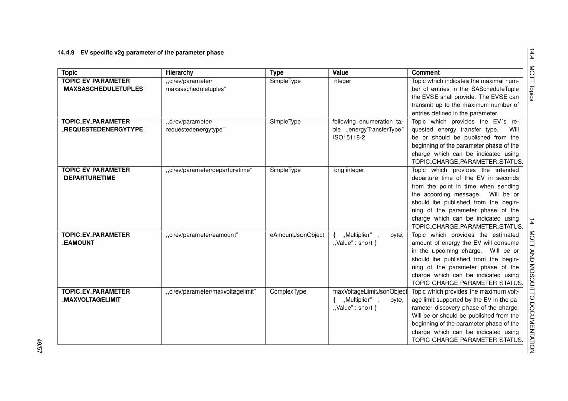
14.4M
QTT
Topics14
MQ
TTA
ND
MO
SQ
UITTO
DO
CU
ME
NTATIO
N
14.4.9 EV specific v2g parameter of the parameter phase
Topic Hierarchy Type Value CommentTOPIC EV PARAMETERMAXSASCHEDULETUPLES
,,ci/ev/parameter/maxsascheduletuples”
SimpleType integer Topic which indicates the maximal num-ber of entries in the SAScheduleTuplethe EVSE shall provide. The EVSE cantransmit up to the maximum number ofentries defined in the parameter.
TOPIC EV PARAMETERREQUESTEDENERGYTYPE
,,ci/ev/parameter/requestedenergytype”
SimpleType following enumeration ta-ble ,,energyTransferType”ISO15118-2
Topic which provides the EV´s re-quested energy transfer type. Willbe or should be published from thebeginning of the parameter phase of thecharge which can be indicated usingTOPIC CHARGE PARAMETER STATUS.
TOPIC EV PARAMETERDEPARTURETIME
,,ci/ev/parameter/departuretime” SimpleType long integer Topic which provides the intendeddeparture time of the EV in secondsfrom the point in time when sendingthe according message. Will be orshould be published from the begin-ning of the parameter phase of thecharge which can be indicated usingTOPIC CHARGE PARAMETER STATUS.
TOPIC EV PARAMETEREAMOUNT
,,ci/ev/parameter/eamount” eAmountJsonObject ,,Multiplier” : byte,,,Value” : short
Topic which provides the estimatedamount of energy the EV will consumein the upcoming charge. Will be orshould be published from the begin-ning of the parameter phase of thecharge which can be indicated usingTOPIC CHARGE PARAMETER STATUS.
TOPIC EV PARAMETERMAXVOLTAGELIMIT
,,ci/ev/parameter/maxvoltagelimit” ComplexType maxVoltageLimitJsonObject ,,Multiplier” : byte,,,Value” : short
Topic which provides the maximum volt-age limit supported by the EV in the pa-rameter discovery phase of the charge.Will be or should be published from thebeginning of the parameter phase of thecharge which can be indicated usingTOPIC CHARGE PARAMETER STATUS.49/57

14.4M
QTT
Topics14
MQ
TTA
ND
MO
SQ
UITTO
DO
CU
ME
NTATIO
N
TOPIC EV PARAMETERMAXCURRENTLIMIT
,,ci/ev/parameter/maxcurrentlimit” ComplexType maxCurrentLimitJsonObject ,,Multiplier” : byte,,,Value” : short
Topic which provides the EVs max-imum current limit supported bythe EV in the parameter discoveryphase of the charge. Will be orshould be published from the begin-ning of the parameter phase of thecharge which can be indicated usingTOPIC CHARGE PARAMETER STATUS.
TOPIC EV PARAMETERMINCURRENTLIMIT
,,ci/ev/parameter/mincurrentlimit” ComplexType minCurrentLimitJsonObject ,,Multiplier” : byte,,,Value” : short
Topic which provides the EVs min-imum current limit supported bythe EV in the parameter discoveryphase of the charge. Will be orshould be published from the begin-ning of the parameter phase of thecharge which can be indicated usingTOPIC CHARGE PARAMETER STATUS.
14.4.10 EV specific v2g parameter of the charge phase
Topic Hierarchy Type Value CommentTOPIC EV CHARGEREADYTOCHARGESTATE
,,ci/ev/charge/readytochargestate” SimpleType following enumeration ta-ble ,,chargeProgressType”ISO15118-2
Topic which provides if the EV is ready tocharge. Will be or should be publishedfrom the END of the parameter phase ofthe charge which can be indicated usingTOPIC CHARGE PARAMETER STATUSOR it will end the pre chargephase which can be indicated usingTOPIC CHARGE PRECHARGE STATUS.
TOPIC EV CHARGECHARGINGPROFILETUPLEID
,,ci/ev/charge/chargingprofiletupleid” SimpleType string Topic which provides the se-lected SAScheduleTupleID from theTOPIC EVSE PARAMETER SASCHEDULELIST.Will be or should be published from thebeginning of the charge phase of thecharge which can be indicated usingTOPIC CHARGE CHARGE STATUS.50/57
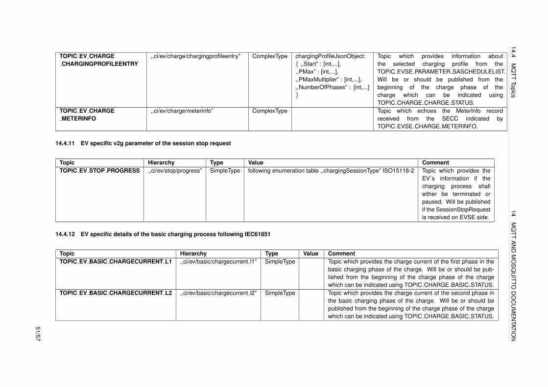
14.4M
QTT
Topics14
MQ
TTA
ND
MO
SQ
UITTO
DO
CU
ME
NTATIO
N
TOPIC EV CHARGECHARGINGPROFILEENTRY
,,ci/ev/charge/chargingprofileentry” ComplexType chargingProfileJsonObject: ,,Start” : [int,...],,,PMax” : [int,...],,,PMaxMultiplier” : [int,...],,,NumberOfPhases” : [int,...]
Topic which provides information aboutthe selected charging profile from theTOPIC EVSE PARAMETER SASCHEDULELIST.Will be or should be published from thebeginning of the charge phase of thecharge which can be indicated usingTOPIC CHARGE CHARGE STATUS.
TOPIC EV CHARGEMETERINFO
,,ci/ev/charge/meterinfo” ComplexType Topic which echoes the MeterInfo recordreceived from the SECC indicated byTOPIC EVSE CHARGE METERINFO.
14.4.11 EV specific v2g parameter of the session stop request
Topic Hierarchy Type Value CommentTOPIC EV STOP PROGRESS ,,ci/ev/stop/progress” SimpleType following enumeration table ,,chargingSessionType” ISO15118-2 Topic which provides the
EV´s information if thecharging process shalleither be terminated orpaused. Will be publishedif the SessionStopRequestis received on EVSE side.
14.4.12 EV specific details of the basic charging process following IEC61851
Topic Hierarchy Type Value CommentTOPIC EV BASIC CHARGECURRENT L1 ,,ci/ev/basic/chargecurrent l1” SimpleType Topic which provides the charge current of the first phase in the
basic charging phase of the charge. Will be or should be pub-lished from the beginning of the charge phase of the chargewhich can be indicated using TOPIC CHARGE BASIC STATUS.
TOPIC EV BASIC CHARGECURRENT L2 ,,ci/ev/basic/chargecurrent l2” SimpleType Topic which provides the charge current of the second phase inthe basic charging phase of the charge. Will be or should bepublished from the beginning of the charge phase of the chargewhich can be indicated using TOPIC CHARGE BASIC STATUS.
51/57

14.4M
QTT
Topics14
MQ
TTA
ND
MO
SQ
UITTO
DO
CU
ME
NTATIO
N
TOPIC EV BASIC CHARGECURRENT L3 ,,ci/ev/basic/chargecurrent l3” SimpleType Topic which provides the charge current of the third phase inthe basic charging phase of the charge. Will be or should bepublished from the beginning of the charge phase of the chargewhich can be indicated using TOPIC CHARGE BASIC STATUS.
TOPIC EV BASIC CHARGEVOLTAGE L1 ,,ci/ev/basic/chargevoltage l1” SimpleType Topic which provides the charge voltage of the first phase in thebasic charging phase of the charge. Will be or should be pub-lished from the beginning of the charge phase of the chargewhich can be indicated using TOPIC CHARGE BASIC STATUS.
TOPIC EV BASIC CHARGEVOLTAGE L2 ,,ci/ev/basic/chargevoltage l2” SimpleType Topic which provides the charge voltage of the second phase inthe basic charging phase of the charge. Will be or should bepublished from the beginning of the charge phase of the chargewhich can be indicated using TOPIC CHARGE BASIC STATUS.
TOPIC EV BASIC CHARGEVOLTAGE L3 ,,ci/ev/basic/chargevoltage l3” SimpleType Topic which provides the charge voltage of the third phase inthe basic charging phase of the charge. Will be or should bepublished from the beginning of the charge phase of the chargewhich can be indicated using TOPIC CHARGE BASIC STATUS.
TOPIC EV BASIC CHARGEPOWER ,,ci/ev/basic/chargepower” SimpleType Topic which provides the charge power in the basic chargingphase of the charge. Will be or should be published from thebeginning of the charge phase of the charge which can be indi-cated using TOPIC CHARGE BASIC STATUS.
TOPIC EV BASIC STARTCHARGE ,,ci/ev/basic/startcharge” SimpleType Topic which indicates if the basic charging phase can be(re)started from EV side. Will be or should be published fromthe beginning of the charge phase of the charge which can beindicated using TOPIC CHARGE BASIC STATUS.
TOPIC EV BASIC STOPCHARGE ,,ci/ev/basic/stopcharge” SimpleType Topic which indicates if the basic charging phase shall bestopped from EV side. Will be or should be published from thebeginning of the charge phase of the charge which can be indi-cated using TOPIC CHARGE BASIC STATUS.
TOPIC EV BASIC ERRORCAUSE ,,ci/ev/basic/errorcause” SimpleType Topic which provides information about an error which has oc-curred. Will be or should be published from the beginning ofthe charge phase of the charge which can be indicated usingTOPIC CHARGE BASIC STATUS.
52/57
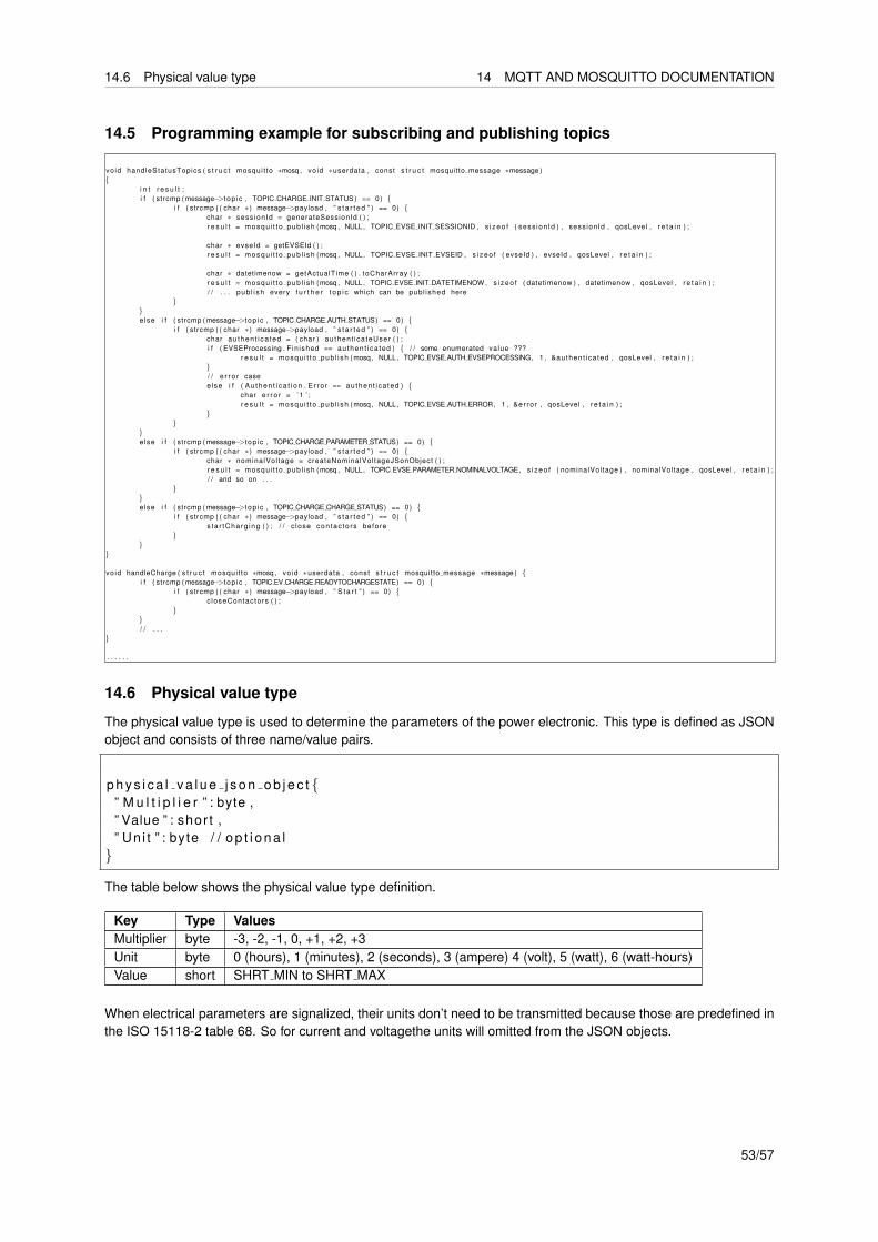
14.6 Physical value type 14 MQTT AND MOSQUITTO DOCUMENTATION
14.5 Programming example for subscribing and publishing topics
vo id handleStatusTopics ( s t r u c t mosqui t to ∗mosq , vo id ∗userdata , const s t r u c t mosquitto message ∗message )
i n t r e s u l t ;i f ( strcmp ( message−>t op ic , TOPIC CHARGE INIT STATUS ) == 0)
i f ( strcmp ( ( char ∗ ) message−>payload , ” s t a r t e d ” ) == 0) char ∗ sess ionId = generateSessionId ( ) ;r e s u l t = mosqu i t t o pub l i sh (mosq , NULL, TOPIC EVSE INIT SESSIONID , s i z e o f ( sess ion Id ) , sessionId , qosLevel , r e t a i n ) ;
char ∗ evseId = getEVSEId ( ) ;r e s u l t = mosqu i t t o pub l i sh (mosq , NULL, TOPIC EVSE INIT EVSEID , s i z e o f ( evseId ) , evseId , qosLevel , r e t a i n ) ;
char ∗ datetimenow = getActualTime ( ) . toCharArray ( ) ;r e s u l t = mosqu i t t o pub l i sh (mosq , NULL, TOPIC EVSE INIT DATETIMENOW , s i z e o f ( datetimenow ) , datetimenow , qosLevel , r e t a i n ) ;/ / . . . pub l i sh every f u r t h e r t o p i c which can be publ ished here
else i f ( strcmp ( message−>t op ic , TOPIC CHARGE AUTH STATUS) == 0)
i f ( strcmp ( ( char ∗ ) message−>payload , ” s t a r t e d ” ) == 0) char au then t i ca ted = ( char ) au thent ica teUser ( ) ;i f ( EVSEProcessing . F in ished == au then t i ca ted ) / / some enumerated value ???
r e s u l t = mosqu i t t o pub l i sh (mosq , NULL, TOPIC EVSE AUTH EVSEPROCESSING, 1 , &authent ica ted , qosLevel , r e t a i n ) ;/ / e r r o r caseelse i f ( Au then t i ca t i on . E r ro r == au then t i ca ted )
char e r r o r = ’ 1 ’ ;r e s u l t = mosqu i t t o pub l i sh (mosq , NULL, TOPIC EVSE AUTH ERROR, 1 , &er ro r , qosLevel , r e t a i n ) ;
else i f ( strcmp ( message−>t op ic , TOPIC CHARGE PARAMETER STATUS) == 0)
i f ( strcmp ( ( char ∗ ) message−>payload , ” s t a r t e d ” ) == 0) char ∗ nominalVol tage = createNominalVoltageJSonObject ( ) ;r e s u l t = mosqu i t t o pub l i sh (mosq , NULL, TOPIC EVSE PARAMETER NOMINALVOLTAGE, s i z e o f ( nominalVol tage ) , nominalVoltage , qosLevel , r e t a i n ) ;/ / and so on . . .
else i f ( strcmp ( message−>t op ic , TOPIC CHARGE CHARGE STATUS) == 0)
i f ( strcmp ( ( char ∗ ) message−>payload , ” s t a r t e d ” ) == 0) s ta r tCharg ing ( ) ; / / c lose con tac to rs before
vo id handleCharge ( s t r u c t mosqui t to ∗mosq , vo id ∗userdata , const s t r u c t mosquitto message ∗message ) i f ( strcmp ( message−>t op ic , TOPIC EV CHARGE READYTOCHARGESTATE) == 0)
i f ( strcmp ( ( char ∗ ) message−>payload , ” S t a r t ” ) == 0) c loseContactors ( ) ;
/ / . . .
. . . . . .
14.6 Physical value type
The physical value type is used to determine the parameters of the power electronic. This type is defined as JSONobject and consists of three name/value pairs.
p h y s i c a l v a l u e j s o n o b j e c t ” M u l t i p l i e r ” : byte ,” Value ” : shor t ,” Un i t ” : byte / / o p t i o n a l
The table below shows the physical value type definition.
Key Type ValuesMultiplier byte -3, -2, -1, 0, +1, +2, +3Unit byte 0 (hours), 1 (minutes), 2 (seconds), 3 (ampere) 4 (volt), 5 (watt), 6 (watt-hours)Value short SHRT MIN to SHRT MAX
When electrical parameters are signalized, their units don’t need to be transmitted because those are predefined inthe ISO 15118-2 table 68. So for current and voltagethe units will omitted from the JSON objects.
53/57
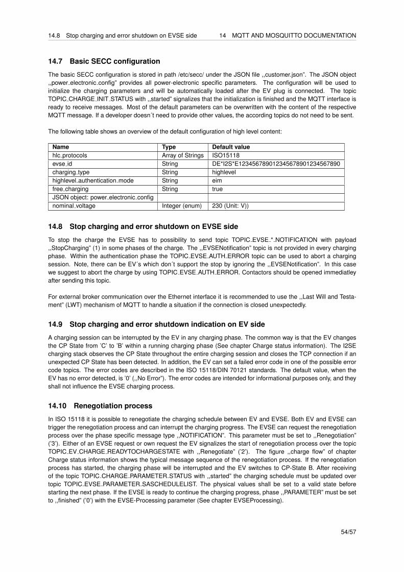
14.8 Stop charging and error shutdown on EVSE side 14 MQTT AND MOSQUITTO DOCUMENTATION
14.7 Basic SECC configuration
The basic SECC configuration is stored in path /etc/secc/ under the JSON file ,,customer.json”. The JSON object,,power electronic config” provides all power-electronic specific parameters. The configuration will be used toinitialize the charging parameters and will be automatically loaded after the EV plug is connected. The topicTOPIC CHARGE INIT STATUS with ,,started” signalizes that the initialization is finished and the MQTT interface isready to receive messages. Most of the default parameters can be overwritten with the content of the respectiveMQTT message. If a developer doesn´t need to provide other values, the according topics do not need to be sent.
The following table shows an overview of the default configuration of high level content:
Name Type Default valuehlc protocols Array of Strings ISO15118evse id String DE*I2S*E123456789012345678901234567890charging type String highlevelhighlevel authentication mode String eimfree charging String trueJSON object: power electronic confignominal voltage Integer (enum) 230 (Unit: V))
14.8 Stop charging and error shutdown on EVSE side
To stop the charge the EVSE has to possibility to send topic TOPIC EVSE * NOTIFICATION with payload,,StopCharging” (1) in some phases of the charge. The ,,EVSENotification” topic is not provided in every chargingphase. Within the authentication phase the TOPIC EVSE AUTH ERROR topic can be used to abort a chargingsession. Note, there can be EV´s which don´t support the stop by ignoring the ,,EVSENotification”. In this casewe suggest to abort the charge by using TOPIC EVSE AUTH ERROR. Contactors should be opened immediatleyafter sending this topic.
For external broker communication over the Ethernet interface it is recommended to use the ,,Last Will and Testa-ment” (LWT) mechanism of MQTT to handle a situation if the connection is closed unexpectedly.
14.9 Stop charging and error shutdown indication on EV side
A charging session can be interrupted by the EV in any charging phase. The common way is that the EV changesthe CP State from ’C’ to ’B’ within a running charging phase (See chapter Charge status information). The I2SEcharging stack observes the CP State throughout the entire charging session and closes the TCP connection if anunexpected CP State has been detected. In addition, the EV can set a failed error code in one of the possible errorcode topics. The error codes are described in the ISO 15118/DIN 70121 standards. The default value, when theEV has no error detected, is ’0’ (,,No Error”). The error codes are intended for informational purposes only, and theyshall not influence the EVSE charging process.
14.10 Renegotiation process
In ISO 15118 it is possible to renegotiate the charging schedule between EV and EVSE. Both EV and EVSE cantrigger the renegotiation process and can interrupt the charging progress. The EVSE can request the renegotiationprocess over the phase specific message type ,,NOTIFICATION”. This parameter must be set to ,,Renegotiation”(’3’). Either of an EVSE request or own request the EV signalizes the start of renegotiation process over the topicTOPIC EV CHARGE READYTOCHARGESTATE with ,,Renegotiate” (’2’). The figure ,,charge flow” of chapterCharge status information shows the typical message sequence of the renegotiation process. If the renegotiationprocess has started, the charging phase will be interrupted and the EV switches to CP-State B. After receivingof the topic TOPIC CHARGE PARAMETER STATUS with ,,started” the charging schedule must be updated overtopic TOPIC EVSE PARAMETER SASCHEDULELIST. The physical values shall be set to a valid state beforestarting the next phase. If the EVSE is ready to continue the charging progress, phase ,,PARAMETER” must be setto ,,finished” (’0’) with the EVSE-Processing parameter (See chapter EVSEProcessing).
54/57
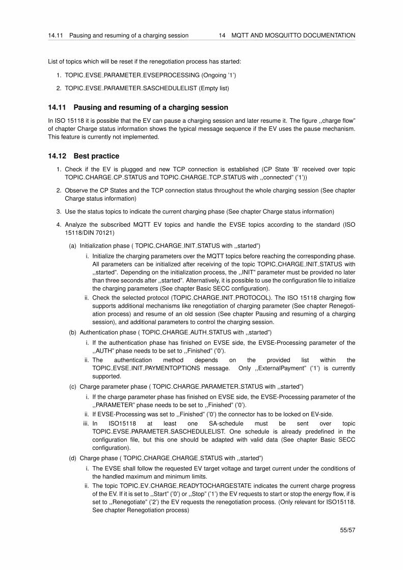
14.11 Pausing and resuming of a charging session 14 MQTT AND MOSQUITTO DOCUMENTATION
List of topics which will be reset if the renegotiation process has started:
1. TOPIC EVSE PARAMETER EVSEPROCESSING (Ongoing ’1’)
2. TOPIC EVSE PARAMETER SASCHEDULELIST (Empty list)
14.11 Pausing and resuming of a charging session
In ISO 15118 it is possible that the EV can pause a charging session and later resume it. The figure ,,charge flow”of chapter Charge status information shows the typical message sequence if the EV uses the pause mechanism.This feature is currently not implemented.
14.12 Best practice
1. Check if the EV is plugged and new TCP connection is established (CP State ’B’ received over topicTOPIC CHARGE CP STATUS and TOPIC CHARGE TCP STATUS with ,,connected” (’1’))
2. Observe the CP States and the TCP connection status throughout the whole charging session (See chapterCharge status information)
3. Use the status topics to indicate the current charging phase (See chapter Charge status information)
4. Analyze the subscribed MQTT EV topics and handle the EVSE topics according to the standard (ISO15118/DIN 70121)
(a) Initialization phase ( TOPIC CHARGE INIT STATUS with ,,started”)
i. Initialize the charging parameters over the MQTT topics before reaching the corresponding phase.All parameters can be initialized after receiving of the topic TOPIC CHARGE INIT STATUS with,,started”. Depending on the initialization process, the ,,INIT” parameter must be provided no laterthan three seconds after ,,started”. Alternatively, it is possible to use the configuration file to initializethe charging parameters (See chapter Basic SECC configuration).
ii. Check the selected protocol (TOPIC CHARGE INIT PROTOCOL). The ISO 15118 charging flowsupports additional mechanisms like renegotiation of charging parameter (See chapter Renegoti-ation process) and resume of an old session (See chapter Pausing and resuming of a chargingsession), and additional parameters to control the charging session.
(b) Authentication phase ( TOPIC CHARGE AUTH STATUS with ,,started”)
i. If the authentication phase has finished on EVSE side, the EVSE-Processing parameter of the,,AUTH” phase needs to be set to ,,Finished” (’0’).
ii. The authentication method depends on the provided list within theTOPIC EVSE INIT PAYMENTOPTIONS message. Only ,,ExternalPayment” (’1’) is currentlysupported.
(c) Charge parameter phase ( TOPIC CHARGE PARAMETER STATUS with ,,started”)
i. If the charge parameter phase has finished on EVSE side, the EVSE-Processing parameter of the,,PARAMETER” phase needs to be set to ,,Finished” (’0’).
ii. If EVSE-Processing was set to ,,Finished” (’0’) the connector has to be locked on EV-side.iii. In ISO15118 at least one SA-schedule must be sent over topic
TOPIC EVSE PARAMETER SASCHEDULELIST. One schedule is already predefined in theconfiguration file, but this one should be adapted with valid data (See chapter Basic SECCconfiguration).
(d) Charge phase ( TOPIC CHARGE CHARGE STATUS with ,,started”)
i. The EVSE shall follow the requested EV target voltage and target current under the conditions ofthe handled maximum and minimum limits.
ii. The topic TOPIC EV CHARGE READYTOCHARGESTATE indicates the current charge progressof the EV. If it is set to ,,Start” (’0’) or ,,Stop” (’1’) the EV requests to start or stop the energy flow, if isset to ,,Renegotiate” (’2’) the EV requests the renegotiation process. (Only relevant for ISO15118.See chapter Renegotiation process)
55/57

15 ORDER INFORMATIONS
5. Initiate a shutdown of the power electronic if the EV indicates stop charging (See chapter Stop charging anderror shutdown indication on EV side) or for EVSE emergency reasons (See chapter Stop charging and errorshutdown on EVSE side).
6. The charging session is terminated by receiving the topic TOPIC CHARGE TCP STATUS with
,,disconnected” (’0’) and TOPIC CHARGE CP STATUS with CP State ’A’.
15 Order Informations
permissible order codes SW Variant Housing HW VariantI2CCSC-P00-100 PWM AC Charging without housing 100I2CCSC-P00-200 PWM AC Charging without housing 200I2CCSC-P00-300 PWM AC Charging without housing 300I2CCSC-A00-100 AC with ISO15118 without housing 100I2CCSC-A00-200 AC with ISO15118 without housing 200I2CCSC-A00-300 AC with ISO15118 without housing 300I2CCSC-P01-100 PWM AC Charging DIN-Rail housing 100I2CCSC-P01-200 PWM AC Charging DIN-Rail housing 200I2CCSC-P01-300 PWM AC Charging DIN-Rail housing 300I2CCSC-A01-100 AC with ISO15118 DIN-Rail housing 100I2CCSC-A01-200 AC with ISO15118 DIN-Rail housing 200I2CCSC-A01-300 AC with ISO15118 DIN-Rail housing 300
56/57

16 DEVICE MARKING
16 Device Marking
Each Device is marked with a label containing the following data:
1. Order Code
2. Serial Number
3. Production Date Code: WWYY
4. 2D DataMatrix code containing the following information as a list of space separated values:
(a) Order Code
(b) MAC address Ethernet1 (only present for variant 200 and 300)
(c) MAC address CP QCA70001 (only present for variant 200 and 300)
(d) MAC address CP QCA7000 Linux interface1 (only present for variant 200 and 300)
(e) MAC address mains QCA70001 (only present for variant 300)
(f) MAC address mains QCA7000 Linux interface1 (only present for variant 300)
(g) DAK mains QCA7000 (only present for variant 300)
(h) Serial Number2
(i) Production Date Code
1: without colons or other delimiters2: 10 digits, with leading zerosAn example is shown in Figure 15.
I2CCSC-A00-200Serial:Datecode:
123453118
Figure 15: Example Label for Charge Control C
57/57