characterization of the effects of use … - patrick j drane with bookmarks...iv and the national...
TRANSCRIPT

CHARACTERIZATION OF THE EFFECTS OF USE AND MOISTURE CONTENT ON BASEBALL BAT PERFORMANCE USING
EXPERIMENTAL METHODS
BY
PATRICK JOSEPH DRANE
ABSTRACT OF A THESIS SUBMITTED TO THE FACULTY OF THE DEPARTMENT OF MECHANICAL ENGINEERING
IN PARTIAL FULLFILMENT OF THE REQUIREMENTS FOR THE DEGREE OF MASTER OF SCIENCE IN MECHANICAL ENGINEEERING
DEPARTMENT OF MECHANICAL ENGINEERING UNIVERSITY OF MASSACHUSETTS LOWELL
2003
Thesis Supervisor: James A Sherwood, Ph.D, P.E. Professor, Department of Mechanical Engineering Copyright © Patrick Joseph Drane, 2003
ii
ABSTRACT
Baseball bat performance has become an issue to players, spectators, regulators
and scientists in recent years. The focus of this thesis is to investigate two conditions that
were thought to have potential effects to the performance of baseball bats. Through
experimental methods, the effect of use is investigated for aluminum bat performance and
the effect of a change in moisture content is investigated for wood bat performance.
Though there is potential for some change in performance, the data and analysis in this
thesis show that the effects are small. In the case of the effect of use, an aluminum bat is
identified to have a nominal increase of less than one mile per hour. The performance
change resulting from a change in moisture content was significant only to the extent of
its dependence on the change of weight of the bat. Although the effects measured are
small, this research constitutes an important addition to the understanding of baseball bat
performance.

iii
ACKNOWLEDGEMENTS
I would like to acknowledge the following individuals for their contributions to
my graduate school education and in particular this thesis.
Prof. James Sherwood has been instrumental in many of my courses and
projects throughout both my undergraduate and graduate education at UMass Lowell. As
a senior, he brought me into the staff of the Baseball Research Center and continued to
give me opportunities to develop both technical and management skills. As my master’s
thesis advisor, he supported my research and critiqued my writing thoroughly.
I would like to thank Prof. Alan Nathan and Prof. Sammy Shina for being
members of my defense committee, critiquing my thesis, and for their efforts in helping
me to understand the statistics required to analyze my data.
Many students, both undergraduate and graduate, have worked in the Baseball
Research Center and were involved in performing many of the tests for this thesis. Those
students are Daniel Hogan, Joseph Armano, Peter Aurora, Stacy Bletsis, Eugene
Esjunin, Natalie Grant, Jeffrey Hodgkins, David Nazzaro, Greg Sandford,
Christopher Silva, Ethan Stowe, Juan Pablo Trelles, Francisco Vicenty, and Gayatri
Vedula.
I would like to acknowledge Dave Cook and Hoosier Bat Company for the
donation of the 20 wood baseball bats used in the effect-of-moisture-content tests.
Additionally, I would like to acknowledge the contributions of Major League Baseball

iv
and the National Collegiate Athletic Association for their support of the Baseball
Research Center and consequently the financial support of my thesis.
The field testing of the aluminum bats in the effect-of-use portion of this thesis
would not have been possible without the support from Coach Jim Stone and the UMass
Lowell Baseball Team.
The microscopy analysis within this thesis was made possible with the help of
Prof. Changmo Sung, his students, especially Maria Ospina, in the Center for
Advance Materials, and his colleagues in Korea that performed some of the tests.
I would also like to thank everyone in the Composites lab for their support and
assistance throughout my graduate degree. Prof. Julie Chen has been there for me to ask
questions. The students are Jennifer Gorczyca, Samuel Chow, Darin Lussier, Samira
Farboodmanesh, Navin Bunyan, Kari White, Xiang Li, and Lu Liu.
Last but definitely not least has been the contribution of my family and friends.
My parents, John and Lucile Drane, as well as my brother, Matthew, have been
instrumental in my completion of my thesis, even though they wondered if I would ever
finish it. Similar credit is also due to my close friends that have put up with me and this
thesis on a day-to-day basis. I want to thank Crystal, Rob, Sarah, Nophie, Amy,
Jeremy, and everyone else that put up with me during the last 2½ years, especially
Crystal.

v
TABLE OF CONTENTS LIST OF FIGURES…….…………………………………………………….…...…… ix LIST OF TABLES ………..……...…………………………………...…......…..…… xiii
1 INTRODUCTION...................................................................................................IX
1.1 MOTIVATION FOR EFFECT OF USE ........................................................................ 3
1.2 MOTIVATION FOR MOISTURE CONTENT STUDY ................................................... 4
1.3 SCOPE................................................................................................................... 6
2 BACKGROUND........................................................................................................ 7
2.1 GENERAL ............................................................................................................. 7
2.1.1 History of Baseball.......................................................................................... 8
2.1.2 Baseball Research Center ............................................................................... 9
2.1.3 Previous Related Research............................................................................ 10
2.2 THEORY ............................................................................................................. 13
2.2.1 Description of Workhardening Process ........................................................ 14
2.2.2 Description of the Effect of Moisture Content on Wood ............................... 15
2.2.2.1 Description of Drying Process (Wood Handbook 1999, (12-5)) .......... 16
2.3 TERMINOLOGY ................................................................................................... 17
3 TEST METHODOLOGY ...................................................................................... 20
3.1 DESCRIPTION OF PRE-EXISTING BAT TEST METHODS USING THE BAUM HITTING
MACHINE ....................................................................................................................... 20
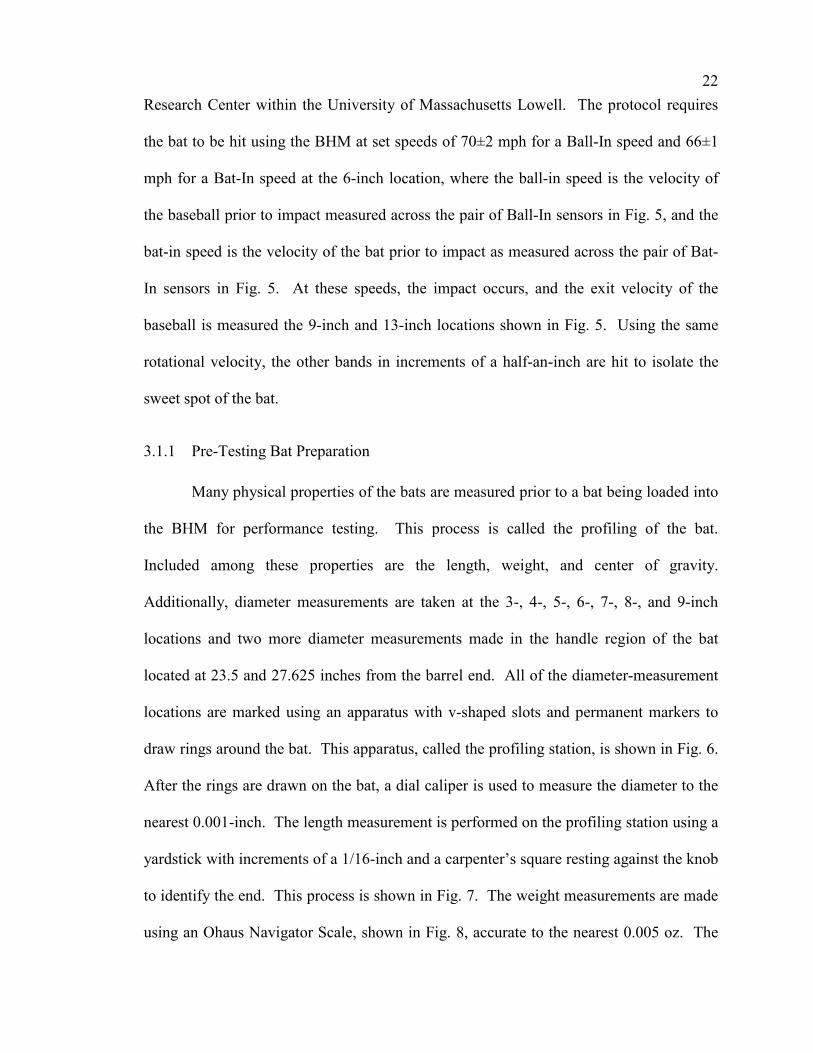
3.1.1 Pre-Testing Bat Preparation......................................................................... 22
3.2 PROCEDURES USED FOR DETERMINING THE EFFECT OF USE ON ALUMINUM
BASEBALL BAT PERFORMANCE...................................................................................... 26
3.2.1 General Aluminum Bat Testing Procedure ................................................... 27
3.2.2 All-in-Machine Method ................................................................................. 29
vi
3.2.2.1 Test Method for PD01........................................................................... 31
3.2.2.1.1 Performance Measurement Method for PD01 .................................. 32
3.2.2.2 Test Method for PD02........................................................................... 34
3.2.2.2.1 Performance Measurement Method .................................................. 34
3.2.2.2.2 Deformation Change Results ............................................................ 35
3.2.2.2.3 Process for Measuring Hardness ....................................................... 36
3.2.2.3 Test Method for PD03........................................................................... 39
3.2.2.3.1 Performance Measurement Method .................................................. 39
3.2.2.3.2 Deformation Change Results ............................................................ 39
3.2.2.3.3 Process for Measuring Hardness ....................................................... 40
3.2.2.3.4 Microscopy Methods......................................................................... 40
3.2.3 Field Use Methods ........................................................................................ 43
3.2.3.1 Test Method for PD04........................................................................... 43
3.2.3.1.1 Test Method for Field Testing........................................................... 44
3.2.3.2 Test Method for PD05........................................................................... 44
3.3 PROCEDURES USED FOR DETERMINING THE EFFECT OF MOISTURE CONTENT ON
WOOD BASEBALL BAT PERFORMANCE .......................................................................... 45
3.3.1 General Wood Bat Testing Procedure .......................................................... 46
3.3.2 Humidification Process ................................................................................. 48
3.3.3 Moisture Content Testing Process ................................................................ 50
3.3.4 Bat Selection Process .................................................................................... 51
3.3.5 Same Weight Method..................................................................................... 52
3.3.6 Same Bat Method .......................................................................................... 53
4 ANALYSIS METHODOLOGY............................................................................. 55
4.1 DATA AND DATA POINTS ................................................................................... 55
4.1.1 Raw Batted-Ball Velocity Data ..................................................................... 56
4.1.2 Ball Exit Speed Ratio (BESR)........................................................................ 57
4.1.3 Adjustments for Ball Lot Certifications......................................................... 61
4.1.4 Adjustment for MOI and Swing Speed .......................................................... 62
4.1.5 Combining of Data........................................................................................ 66
4.2 EXPLANATION OF STATISTICAL METHODS FOR ANALYZING DATA.................... 67
vii
4.2.1 General Statistical Background .................................................................... 68
4.2.2 T-test.............................................................................................................. 69
4.2.3 Control Charts and Confidence Intervals ..................................................... 72
4.3 PLOTTING TERMINOLOGY .................................................................................. 74
5 RESULTS / DISCUSSION ..................................................................................... 75
5.1 RESULTS OF EFFECT-OF-USE TESTS.................................................................... 75
5.1.1 Results of PD01............................................................................................. 76
5.1.1.1 Performance Results of PD01 ............................................................... 76
5.1.2 Results of PD02............................................................................................. 94
5.1.2.1 Performance Results for PD02.............................................................. 95
5.1.2.2 Surface-Deformation Results for PD02 ................................................ 96
5.1.2.3 Hardness Results for PD02 ................................................................... 98
5.1.3 Results of PD03............................................................................................. 99
5.1.3.1 Performance Results for PD03............................................................ 100
5.1.3.2 Surface-Deformation Results for PD03 .............................................. 116
5.1.3.3 Hardness Results for PD03 ................................................................. 118
5.1.3.4 Microscopy Results for PD03 ............................................................. 122
5.1.4 Results of PD04........................................................................................... 125
5.1.4.1 Performance Results of PD04 ............................................................. 126
5.1.4.2 Surface-deformation Results of PD04................................................. 139
5.1.5 Results of PD05........................................................................................... 141
5.1.5.1 Performance Results of PD05 ............................................................. 142
5.1.5.2 Surface-deformation Results of PD05................................................. 146
5.1.6 Summary of Effect-of-Use Results............................................................... 148
5.2 RESULTS OF EFFECT-OF-MOISTURE-CONTENT TESTS....................................... 149
5.2.1 Results of Same-Weight-Method Tests ........................................................ 150
5.2.2 Results of Same-Bat-Method Tests.............................................................. 156
5.2.3 Summary of Effect-of-Moisture-Content Results......................................... 160
6 CONCLUSIONS ................................................................................................... 161
7 RECOMMENDATIONS...................................................................................... 162
viii
8 LITERATURE CITED......................................................................................... 165
APPENDIX A: NCAA CERTIFICATION PROTOCOL …………….…………… .A-1
APPENDIX B: BAUM HITTING MACHINE PATENT ………….……….……… B-1
APPENDIX C: BHM DATASHEET ………….…………………………..………… C-1
APPENDIX D: VISUAL BASIC PROGRAM FOR CALCULATING MOI …..… D-1
APPENDIX E: REQUIREMENTS FOR A VALID HIT ………………..………… E-1
APPENDIX F: MOISTURE CONTENT TEST DATA WORKSHEET ………..… F-1
APPENDIX G: CALCULATIONS FOR MOI ADJUSTMENT CONSTANT …... G-1
APPENDIX H: GAUSSIAN DISTRIBUTION ANALYSIS OF BHM DATA..…... H-1
APPENDIX I: WORKSHEET FOR CALCULATING T-TEST PROB......……...... I-1

ix
LIST OF FIGURES FIG. 1: PARTS OF BASEBALL BAT........................................................................................ 18
FIG. 2: TARGETING DIAMOND FOR BHM............................................................................ 18
FIG. 3: SCHEMATIC OF BHM (MUSTONE 1998) ................................................................. 21
FIG. 4: VIEW OF BHM IN UMLBRC FROM TOP CORNER ................................................... 21
FIG. 5: DIAGRAM OF PHOTOELECTRIC SENSORS IN BHM ................................................... 21
FIG. 6: PROFILING STATION................................................................................................ 24
FIG. 7: USE OF CARPENTER'S SQUARE WITH PROFILING STATION........................................ 24
FIG. 8: OHAUS SCALE MEASURING WEIGHT OF A BASEBALL............................................... 25
FIG. 9: BALANCING OF BATS ON ANGLE IRON TO DETERMINE CG ...................................... 25
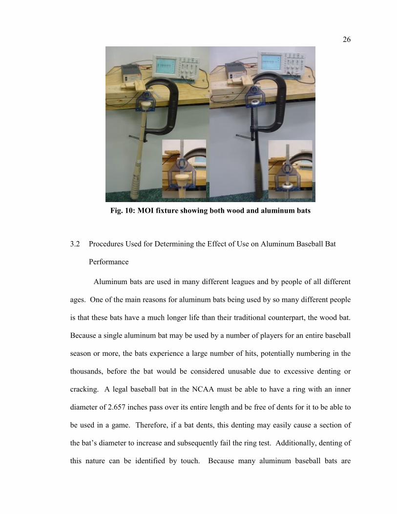
FIG. 10: MOI FIXTURE SHOWING BOTH WOOD AND ALUMINUM BATS ................................ 26
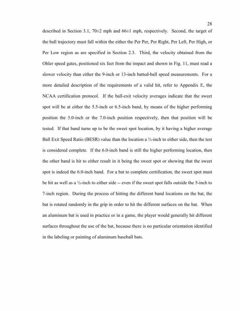
FIG. 11: CHECK CELL SPEED GATE FOR BHM..................................................................... 29
FIG. 12: SURFACE DEFORMATION SETUP ............................................................................ 36
FIG. 13: ROCKWELL HARDNESS TESTER ............................................................................. 38
FIG. 14: TEM AT CENTER FOR ADVANCED MATERIALS .................................................... 42
FIG. 15: AFM AT CENTER FOR ADVANCED MATERIALS.................................................... 42
FIG. 16: WRAPPING OF HANDLE OF WOOD BAT FOR REINFORCEMENT ................................ 48
FIG. 17: HUMIDITY CHAMBER (LEFT) AND HUMIDIFIER (RIGHT)......................................... 49
FIG. 18: BATTED-BALL VELOCITY AS A FUNCTION OF INBOUND BAT VELOCITY ................. 65
FIG. 19: AEV OF THE SWEET SPOT FOR EACH CERTIFICATION CYCLE WITH BASELINE FOR
PD01.......................................................................................................................... 78
FIG. 20: AEV OF THE SWEET SPOT – ADJUSTED FOR BASELINE FOR PD01 ......................... 78
FIG. 21: BESR BASED AVERAGE BATTED-BALL VELOCITY FOR THE SWEET SPOT FOR PD01
................................................................................................................................... 79
FIG. 22: AEV OF ALL 25 VALID HITS FOR EACH CERTIFICATION CYCLE WITH BASELINE FOR
PD01.......................................................................................................................... 81
FIG. 23: AEV OF ALL 25 HITS – ADJUSTED FOR BASELINE FOR PD01 ................................ 81
x
FIG. 24: BESR BASED AEV FOR ALL 25 HITS FOR PD01................................................... 82
FIG. 25: CONTROL CHART ANALYSIS FOR AEV OF THE SWEET SPOT FOR PD01................. 84
FIG. 26: CONTROL CHART ANALYSIS FOR BESR FOR THE SWEET SPOT FOR PD01 ............. 86
FIG. 27: CONTROL CHART ANALYSIS FOR AEV FOR THE ALL 25 HITS FOR PD01............... 88
FIG. 28: CONTROL CHART ANALYSIS FOR BESR-BASED AEV FOR ALL 25 HITS FOR PD0190
FIG. 29: ANALYSIS OF LUMPED AEV OF THE SWEET SPOT FOR PD01................................. 92
FIG. 30: ANALYSIS OF LUMPED BESR-BASED AEV OF THE SWEET SPOT FOR PD01.......... 92
FIG. 31: ANALYSIS OF LUMPED AEV FOR ALL 25 HITS FOR PD01 ..................................... 93
FIG. 32: ANALYSIS OF LUMPED BESR-BASED AEV FOR ALL 25 HITS FOR PD01............... 93
FIG. 33: CONTROL CHART ANALYSIS FOR BESR-BASED AEV FOR ALL 25 HITS FOR PD02
................................................................................................................................... 95
FIG. 34: SURFACE-DEFORMATION PLOT FOR 5.0-INCH BAND FOR PD02............................. 97
FIG. 35: SURFACE-DEFORMATION PLOT FOR 6.0-INCH BAND FOR PD02............................. 97
FIG. 36: SURFACE-DEFORMATION PLOT FOR 7.0-INCH BAND FOR PD02............................. 98
FIG. 37: ROCKWELL HARDNESS MEASUREMENTS FOR PD02.............................................. 99
FIG. 38: AEV OF THE SWEET SPOT FOR PD03 .................................................................. 101
FIG. 39: BESR-BASED AEV OF THE SWEET SPOT FOR PD03............................................ 102
FIG. 40: AEV OF ALL 25 HITS FOR EACH CERTIFICATION CYCLE FOR PD03 ..................... 102
FIG. 41: BESR-BASED AEV FOR ALL 25 HITS FOR PD03................................................. 103
FIG. 42: CONTROL CHART ANALYSIS FOR AEV OF THE SWEET SPOT FOR PD03............... 106
FIG. 43: CONTROL CHART ANALYSIS FOR BESR-BASED AEV FOR THE SWEET SPOT FOR
PD03........................................................................................................................ 108
FIG. 44: CONTROL CHART ANALYSIS FOR AEV FOR ALL 25 HITS FOR PD03.................... 111
FIG. 45: CONTROL CHART ANALYSIS FOR THE BESR-BASED AEV FOR ALL 25 HITS FOR
PD03........................................................................................................................ 113
FIG. 46: ANALYSIS OF LUMPED AEV OF THE SWEET SPOT FOR PD03............................... 114
FIG. 47: ANALYSIS OF LUMPED BESR-BASED AEV OF THE SWEET SPOT FOR PD03........ 114
FIG. 48: ANALYSIS OF LUMPED AEV FOR ALL 25 HITS FOR PD03 ................................... 115
FIG. 49: ANALYSIS OF LUMPED BESR-BASED AEV FOR ALL 25 HITS FOR PD03............. 115
FIG. 50: SURFACE-DEFORMATION PLOT FOR 5.0-INCH BAND FOR PD03........................... 117
FIG. 51: SURFACE-DEFORMATION PLOT FOR 6.0-INCH BAND FOR PD03........................... 117

xi
FIG. 52: SURFACE-DEFORMATION PLOT FOR 7.0-INCH BAND FOR PD03........................... 118
FIG. 53: ROCKWELL HARDNESS MEASUREMENTS FOR PD03............................................ 119
FIG. 54: VICKERS HARDNESS MEASUREMENTS FOR PD03 ................................................ 120
FIG. 55: SAMPLE LOCATIONS IDENTIFIED IN PICTURE OF BARREL OF PD03 ...................... 120
FIG. 56: VOLUME FRACTION OF GRAIN BOUNDARIES FROM TEM ANALYSIS FOR PD03 ... 123
FIG. 57: TEM IMAGE FROM 2-INCH LOCATION OF PD03 .................................................. 124
FIG. 58: AFM 3-D IMAGE OF THE SURFACE ROUGHNESS OF 6-INCH LOCATION OF PD03. 124
FIG. 59: AEV OF THE SWEET SPOT FOR PD04 .................................................................. 128
FIG. 60: BESR-BASED AEV OF THE SWEET SPOT FOR PD04............................................ 128
FIG. 61: AEV OF 15 HITS AT 5.0-, 5.5- AND 6.0-INCH POSITIONS FOR PD04 .................... 129
FIG. 62: BESR-BASED AEV AT 5.0-, 5.5- AND 6.0-INCH POSITIONS FOR PD04 ............... 129
FIG. 63: CONTROL CHART ANALYSIS FOR AEV OF THE SWEET SPOT FOR PD04............... 131
FIG. 64: CONTROL CHART ANALYSIS FOR BESR-BASED AEV FOR THE SWEET SPOT FOR
PD04........................................................................................................................ 132
FIG. 65: CONTROL CHART ANALYSIS OF AEV FOR 5.0-, 5.5- AND 6.0-INCH LOCATIONS FOR
PD04........................................................................................................................ 134
FIG. 66: CONTROL CHART ANALYSIS FOR THE BESR-BASED AEV FOR 5.0-, 5.5- AND 6.0-
INCH LOCATIONS FOR PD04...................................................................................... 135
FIG. 67: ANALYSIS OF LUMPED AEV OF THE SWEET SPOT FOR PD04............................... 137
FIG. 68: ANALYSIS OF LUMPED BESR-BASED AEV OF THE SWEET SPOT FOR PD04........ 137
FIG. 69: ANALYSIS OF LUMPED AEV FOR 5.0-, 5.5- AND 6.0-INCH LOCATIONS FOR PD04
................................................................................................................................. 138
FIG. 70: ANALYSIS OF LUMPED BESR-BASED AEV FOR 5.0-, 5.5- AND 6.0-INCH
LOCATIONS FOR PD04 .............................................................................................. 138
FIG. 71: SURFACE-DEFORMATION PLOT FOR 5.0-INCH BAND FOR PD04........................... 140
FIG. 72: SURFACE-DEFORMATION PLOT FOR 6.0-INCH BAND FOR PD04........................... 140
FIG. 73: SURFACE-DEFORMATION PLOT FOR 7.0-INCH BAND FOR PD04........................... 141
FIG. 74: CONTROL CHART ANALYSIS FOR AEV OF THE SWEET SPOT FOR PD05............... 143
FIG. 75: CONTROL CHART ANALYSIS FOR BESR-BASED AEV FOR THE SWEET SPOT FOR
PD05........................................................................................................................ 144
FIG. 76: CONTROL CHART ANALYSIS OF AEV FOR ALL 30 HITS FOR PD05 ...................... 144

xii
FIG. 77: CONTROL CHART ANALYSIS FOR THE BESR-BASED AEV FOR ALL 30 HITS FOR
PD05........................................................................................................................ 145
FIG. 78: SURFACE-DEFORMATION PLOT FOR 5.0-INCH BAND FOR PD05........................... 147
FIG. 79: SURFACE-DEFORMATION PLOT FOR 6.0-INCH BAND FOR PD05........................... 147
FIG. 80: SURFACE-DEFORMATION PLOT FOR 7.0-INCH BAND FOR PD05........................... 148
FIG. 81: MEASURED AEV FROM SWEET SPOT AS FUNCTION OF MOISTURE CONTENT ....... 155
FIG. 82: BESR-BASED AEV FROM SWEET SPOT AS FUNCTION OF MOISTURE CONTENT.... 155
FIG. A1: BHM TARGET WINDOW .....................................................................................A-4
FIG. C1: SAMPLE BHM DATASHEET ............................................................................... C-1
FIG. D1: VISUAL BASIC PROGRAM TO CALCULATE MOI..................................................D-1
FIG. G1: DESCRIPTION OF RADIAL AND TANGENTIAL DIRECTIONS ON WOOD BAT ............G-2
FIG. H1: HISTOGRAM OF ADJUSTED DATA POINTS FOR CYCLES 4 THROUGH 26 OF PD03.H-3
xiii
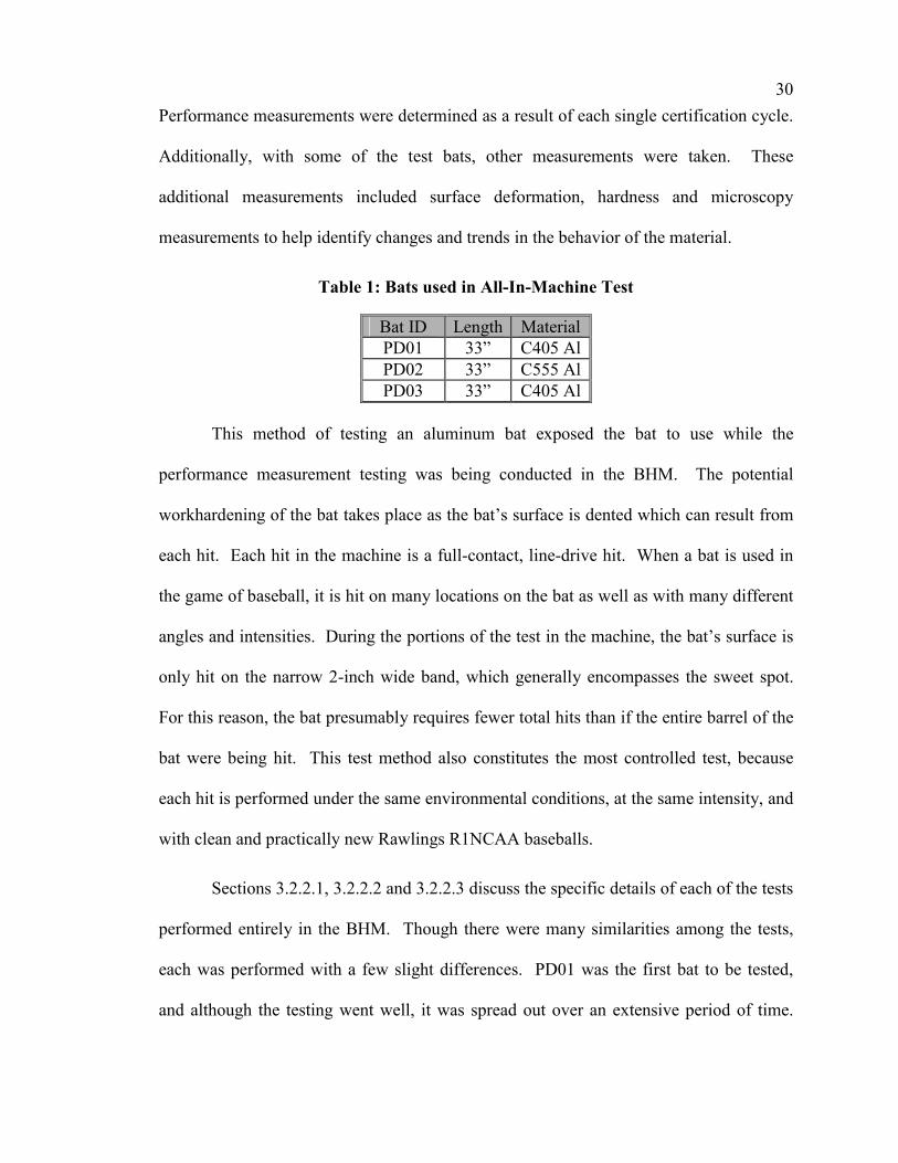
LIST OF TABLES TABLE 1: BATS USED IN ALL-IN-MACHINE TEST ............................................................... 30
TABLE 2: BALL LOT PERFORMANCE COMPARISONS FOR PD01 .......................................... 33
TABLE 3: SYMBOLS USED IN GRAPHS OF EFFECT-OF-USE RESULTS ..................................... 74
TABLE 4: T-TEST RESULTS OF PROBABILITY FOR PD01 OF AEV FOR THE SWEET SPOT...... 83
TABLE 5: T-TEST RESULTS OF PROBABILITY FOR PD01 OF BESR FOR THE SWEET SPOT .... 85
TABLE 6: T-TEST RESULTS OF PROBABILITY FOR PD01 OF AEV FOR ALL 25 HITS ............. 87
TABLE 7: T-TEST RESULTS OF PROBABILITY FOR PD01 OF BESR FOR ALL 25 HITS ........... 89
TABLE 8: SUMMARY OF LUMPED ANALYSIS TO DETERMINE MAGNITUDE FOR PD01 .......... 94
TABLE 9: SUMMARY OF CONTROL CHART ANALYSIS TO DETERMINE MAGNITUDE OF CHANGE
................................................................................................................................... 96
TABLE 10: T-TEST RESULTS OF PROBABILITY FOR PD03 OF AEV FOR THE SWEET SPOT .. 105
TABLE 11: T-TEST RESULTS OF PROBABILITY FOR PD03 OF BESR-BASED AEV FOR THE
SWEET SPOT.............................................................................................................. 107
TABLE 12: T-TEST RESULTS OF PROBABILITY FOR PD03 OF AEV FOR ALL 25 HITS ......... 110
TABLE 13: T-TEST RESULTS OF PROBABILITY FOR PD03 OF BESR-BASED AEV FOR ALL 25
HITS.......................................................................................................................... 112
TABLE 14: SUMMARY OF LUMPED ANALYSIS TO DETERMINE MAGNITUDE FOR PD03 ...... 116
TABLE 15: T-TEST RESULTS OF PROBABILITY FOR PD04 OF AEV FOR THE SWEET SPOT .. 131
TABLE 16: T-TEST RESULTS OF PROBABILITY FOR PD04 OF BESR-BASED AEV FOR THE
SWEET SPOT.............................................................................................................. 132
TABLE 17: T-TEST RESULTS OF PROBABILITY FOR PD04 OF AEV FOR 5.0-, 5.5- AND 6.0-
INCH LOCATIONS ...................................................................................................... 133
TABLE 18: T-TEST RESULTS OF PROBABILITY FOR PD04 OF BESR-BASED AEV FOR 5.0-,
5.5- AND 6.0-INCH LOCATIONS ................................................................................. 135
TABLE 19: SUMMARY OF LUMPED ANALYSIS TO DETERMINE MAGNITUDE FOR PD04 ...... 139
TABLE 20: T-TEST RESULTS OF PROBABILITY FOR PD05 .................................................. 143

xiv
TABLE 21: SUMMARY OF CONTROL CHART ANALYSIS TO DETERMINE MAGNITUDE OF
CHANGE FOR PD05................................................................................................... 146
TABLE 22: SUMMARY OF EFFECT-OF-USE PERFORMANCE TESTS ...................................... 149
TABLE 23: LENGTHS AND WEIGHTS OF BATS RECEIVED FOR EFFECT-OF-MOISTURE-CONTENT
TESTS........................................................................................................................ 150
TABLE 24: WEIGHTS AND MOIS OF BATS AT TIME OF TESTING ........................................ 151
TABLE 25: MOISTURE CONTENT (MC) OF BATS ............................................................... 152
TABLE 26: PERFORMANCE AT SWEET SPOT ...................................................................... 153
TABLE 27: SAME-WEIGHT METHOD SUMMARY................................................................. 154
TABLE 28: WEIGHTS OF BATS AS TESTED AND PREDICTED CHANGE IN MOI BETWEEN TESTS
................................................................................................................................. 157
TABLE 29: MOISTURE CONTENTS OF BATS ....................................................................... 157
TABLE 30: PERFORMANCE OF BATS.................................................................................. 158
TABLE 31: T-TEST OF RESULTS FOR EACH BAT ................................................................. 159
TABLE 32: PAIRED T-TEST OF RESULTS FOR SAME-BAT-METHOD ..................................... 160
TABLE 33: SUMMARY OF EFFECT-OF-INCREASED-MOISTURE-CONTENT PERFORMANCE TESTS
................................................................................................................................. 160
TABLE A1: LENGTH CLASSES FOR BATS ...........................................................................A-1
TABLE A2: WEIGHT CLASSES FOR BATS WITHOUT GRIP ...................................................A-2
TABLE G1: DIAMETER MEASUREMENTS ALONG SURFACE OF WOOD BAT (MODEL 235)....G-4
TABLE G2: POSITION AND SURFACE AREA USED TO GENERATE MOI FOR EACH INCH
SECTION ...................................................................................................................G-5
TABLE H1: NUMBER OF DATA POINTS COUNTED IN EACH RANGE.....................................H-2
1
1 INTRODUCTION
In the game of baseball, like in any sport, there are conditions where small
changes can make a big difference. In golf, there is a big difference between getting the
ball in the cup and having it roll near the edge of the cup. In soccer or hockey, there is a
big difference between hitting the pole of the goal and getting it in the net. In baseball,
there is a big difference between having the ball caught by the outfielder at the wall and
the ball flying over the top of the wall. In all of these cases, an inch can make a big
difference.
If baseball were played, for instance, on a field with no fences or boundaries, the
impact of hitting the baseball a few extra feet would make a difference, but often not a
crucial difference. The game of baseball at a competitive level is not played on
unbounded fields. Most baseball is played in stadiums with very defined field
boundaries, set by walls and lines. When the baseball is hit over those boundaries, the
few-feet difference is a homerun instead of a potential fly out. Many college and
professional players are capable of hitting the ball out of the park for a homerun, but
more often than hitting a homerun, the players will hit the ball into the outfield near the
wall. Therefore, the effect of a few feet can make a significant difference. These
differences may be the result of several factors: the player strength and skill, the size of
the ballpark, the environmental conditions at the ballpark, the construction of the
baseball, and/or the baseball bat.

2
Though baseball has evolved since its beginning in the mid-1800s, many aspects
of the game have remained constant. At the professional level, Major League Baseball
(MLB), the regulatory body overseeing professional baseball in the United States, has
imposed regulations to ensure consistency to the game. These regulations are important
because many people have kept statistics on players, teams, and trends over many years.
The integrity of a record-breaking event relies on the consistency of the other conditions
surrounding the event. One aspect of record keeping is to identify the changes in a
player’s ability to play the game. Therefore, players’ strengths and skills are allowed to
change by natural ability and training. Ideally, all other effects would remain the same
except, for instance, the environmental conditions at the open-air ballparks are
uncontrollable. The National Collegiate Athletic Association (NCAA) and MLB do,
although, loosely regulate the size of ballparks by setting minimum distance to the
outfield wall and the backstop in their respective rulebooks. Lastly, the construction of
the baseball and changes in the baseball bat are some of the key factors that can and need
to be monitored and controlled so as to further ensure that the equipment aspects of the
game remain unchanged.
The need for testing baseball bats and baseballs in a controlled laboratory
environment was what led to the establishment of the University of Massachusetts Lowell
Baseball Research Center (UMLBRC) in 1998. Under laboratory conditions and using
test procedures partially developed as part of an NCAA bat certification protocol, the
construction and changes in baseballs and bats can be investigated and monitored.
Because the testing is performed in a very controlled manner, small changes that can
impact the game can be investigated using equipment in the lab.

3
It is very important to understand how the performance of baseball bats can
change after the bat is manufactured. MLB inherently controls bat performance by
allowing the use of only solid wood bats. Other governing organizations, including the
NCAA and the National Federation of High Schools (NFHS), regulate baseball bat
performance by implementing a certification process for each model/length/weight of bat
used by their teams. Two forms of performance effecting properties will be considered
within this thesis
· the effect of repeated use of aluminum bats and
· the effect of moisture content on wood bats.
1.1 Motivation for Effect of Use
The motivation for conducting an effect-of-use study of aluminum bats came
from the college and high school level of sports, because they are major users of
aluminum baseball bats and have regulations in place limiting bat performance. In 1998,
the governing body of college sports, the NCAA, decided to regulate collegiate baseball
bat performance. Thus, a limit on the batted-ball speed was instituted. As part of this
regulation, each model/length/weight combination of baseball bat is submitted for
certification at the UMLBRC when the bat is new.
Aluminum, being a metal, can potentially harden as a result of being plastically
deformed. An aluminum baseball bat is often plastically deformed during impact and can
therefore potentially increase its yield strength. This change in yield strength can
increase the bat’s potential to store energy during the bat-ball collision and therefore
potentially transfer more energy to the baseball than would otherwise occur without the

4
hardening. While this is the theory from a materials standpoint, players and coaches say
from their experiences that a bat will become lower performing, “deader”, as the season
progresses. To explore these conflicting viewpoints, it was decided to conduct an
extensive scientific study that would track the performance of aluminum baseball bats as
they are used and eventually become cracked and dented.
The NCAA is unaware as to what happens to the performance of the bat as it is
used during the baseball season. Recall that players and coaches contend that the
performance decreases as the season progresses and that the theory of workhardening, to
be explained in detail in Section 2.2.1, implies that the performance is likely to increase
because of changes in the microstructure of the impacted aluminum. Some people are
concerned that a bat which passes the original certification by a very small margin and
subsequently shows a performance increase resulting from its use during the season may
then exceed the same certification limit which that particular bat model/length/weight
combination passed when it was new. It is therefore very important to know if
workhardening does take place and its impact on the performance evolution of the
aluminum bat.
1.2 Motivation for Moisture Content Study
A study of the effects of moisture content on a wood bat’s performance is
important at the major league level especially, but also at other levels. The moisture
content of wood varies significantly from when the wood is in a living tree, greater than
30%, to when it is used in products, less than 16%. Wood is generally dried to the
moisture content that it will experience when it is used with the intent of avoiding the
formation of defects. For example, wood used in furniture is dried to about 6% to avoid

5
cracking during the dry winter months. Wood used for making baseball bats is dried to a
moisture content of about 12%. After wood bats leave the manufacturer, they are
exposed to varying environmental conditions across the country such as natural and
controlled humidities and temperatures. The fact that some players are controlling the
storage conditions leads one to believe that there is a perceived benefit to environmental
conditions. The moisture content of a wood bat will slowly change to adjust to the
equilibrium moisture content defined by its environmental conditions. Because the
drying of wood will increase its stiffness (Wood Handbook 1999, (4-4)) and the increased
stiffness allows more energy to be stored in the bat during the collision, wood bat
performance could be expected to increase as the moisture content decreases if this were
the only property of the bat to change.
The change in weight due to the change in moisture content can also have two
direct effects on the performance of the bat. An increase in moisture content by 3 to 4%
will increase the weight of a typical bat by about an ounce. This change in weight makes
the barrel end of the bat more massive thereby transferring more energy to the ball during
impact. However, the increased mass also increases the moment of inertia thereby
slowing the swing speed of the bat into the impact. Because these factors oppose each
other, the resulting performance change may be small or insignificant, but both factors
continue to affect the way the player approaches batting.
In recent years, some players have tried to obtain improved hitting performance
by legally making modifications to the bats. Some methods have included controlling the
moisture content by storing their bats in humidors. Increasing the moisture content of the
bat may lead to increased bat breakage because the modulus of rupture will decrease
6
(Wood Handbook 1999, (4-4)). Decreasing the moisture content may lead to less bat
breakage, but the bat may break more catastrophically because the bat will be more
brittle, i.e. less tough (Wood Handbook 1999, (4-24)). Though this thesis will not
address durability of wooden bats, it will show the effect on the performance of this
natural and human controlled modification to the bat.
The NCAA also has an interest in knowing the significance of the effects of the
moisture content on wood bat performance because 34-inch, 31-ounce northern white ash
set the standard for the performance of all non-solid-ash bats used in NCAA competition.
Therefore, this thesis will also consider the question of how performance and moisture
content are related with respect to the use of wood bats.
1.3 Scope
The scope of this thesis is to inspect, through experimental methods and statistical
analysis, factors that affect baseball bat performance after the bat has been manufactured.
Within this topic, aluminum bat performance will be tracked as bats are exposed to
extensive use and wood bat performance will be examined as the moisture content is
varied. With respect to aluminum bats, a combination of controlled laboratory testing
and field-testing will be used to determine if workhardening or other changes due to use
of the bat effect the performance through its life. Likewise, two test methods will be used
to inspect the effect of moisture content on wood bat performance: one limiting the
variability on the bat’s weight, and the other limiting the variability from bat to bat, by
testing the same bats under both moisture content conditions. Conclusions will then be
presented identifying both the trends and the magnitudes of any effects along with any
other pertinent discoveries.
7
2 BACKGROUND
To understand the topics of the performance effects of aluminum baseball bat use
and the effect of moisture content on wood bat performance, Chapter 2 will detail some
helpful background. Section 2.1 will introduce some general topics related to the history
of baseball, the UMLBRC, and related research. Section 2.2 will then describe the
theory of workhardening and changes in moisture content. Lastly, Section 2.3 will define
some terminology used throughout the thesis.
2.1 General
Though much of the background presented in Chapter 2 details the scientific
principles related to the thesis scope, this sub-section will describe other pertinent
information to help relate it to the bigger picture. Section 2.1.1 will briefly outline the
history of baseball, identifying specifically the history of the uses of different styles of
baseball bats. Because all of the testing performed as part of this thesis was performed
through the UMLBRC, a brief description and history of the Baseball Research Center is
included in Section 2.1.2. Though most of the research on baseball bat performance is
likely proprietary within the individual manufacturers, several scientists have worked to
better understand the performance of bats. Section 2.1.3 briefly describes some of the
related research topics of these scientists.

8
2.1.1 History of Baseball
The game of baseball is known as America’s pastime. Though the game is
credited by some as being invented in Cooperstown, New York, in 1839 by Abner
Doubleday, the game resembles that of an English game called Rounders, which existed
prior to 1839 (Watts 1990, 1-12). During the early 1840’s, organized baseball teams
developed in New York where the Washington and Knickerbocker Baseball Clubs
formed (Britannica 1911). With the formation of new teams, baseball became a
gentleman’s game and proceeded to spread first through the Northeastern portion of
America and then continued to expand west as modes of transportation became easier.
The first professional baseball team was formed in 1869 and called the Cincinnati Red
Stockings. The National League, which was established in 1871, was the first
professional league (Encyclopedia 2003). College baseball began in 1879 with several of
the Ivy League Schools (Britannica 1911). During the twentieth century, baseball spread
throughout all age groups, races, and social classes making it America’s pastime.
Baseball bats originally were made of wood. Currently, ash is the most common
wood for baseball bats and the weights of the bat are generally less than 36 ounces.
Through the history of baseball, this has not always been the case. During the era of
Babe Ruth, in the 1920’s and 30’s, the typical bat weighed more than 36 ounces (Adair
1994, 108-111). Additionally, the wood types varied, and hickory was a very common
choice. Babe Ruth was said to have swung a bat as heavy as 56 ounces in his early years
(Adair 1994, 108-111).
Hillerich and Bradsby, commonly known as Louisville Slugger, Easton Sports,
and Worth Sports were developing and selling aluminum bats made from high-
9
performance aluminum alloys in 1970 (Louisville 2003, McNamee 2003 and Worth
2003). Aluminum bats were developed in cooperation with Little League, which by this
time had established itself as the governing youth baseball organization throughout the
world. In 1971, aluminum bats were first used in Little League games (Little League
2003). Three years later, aluminum bats were allowed for use in the College World
Series (SportsLine 2003). Aluminum bats were initially purchased as a cost effective
remedy to the problem of wood bat breakage. During the early 1990’s, aluminum bat
manufacturers began to develop high-performing aluminum baseball bats. This period of
aggressive development continued until 1998, when the NCAA stepped in to regulate the
performance of aluminum bats. Though essentially still cost effective today, some
aluminum bats can sell for as much as $300 a piece.
2.1.2 Baseball Research Center
The University of Massachusetts Lowell Baseball Research Center (UMLBRC)
was established in 1998 for the primary purpose of being an independent testing
laboratory to conduct bat certifications for different governing bodies in baseball. Bats
are tested most commonly for the NCAA, which requires that baseball bats used in
collegiate competition perform at a level no greater than that set by a 34-inch/31-ounce
northern white ash standard. Testing of bats has also been completed for the NFHS,
which governs high school baseball, and for MLB, which governs professional baseball.
The UMLBRC primarily uses a hitting machine called the Baum Hitting Machine (BHM)
for conducting the performance testing. This machine swings both the bat and the
baseball into the hit. The inbound bat and baseball speeds are measured as well as the
batted ball speed. The strength of this machine is that the baseball and bat enter the

10
impact at speeds comparable to those that are pitched and swung, respectively, under
actual game conditions.
While the majority of the UMLBRC’s work is bat certifications, the lab has the
ability to perform tests that serve the purpose of maintaining the spirit of the rules that the
governing bodies have set. The BHM is capable of measuring smaller, but important,
differences in baseball bat performance than any type of field-testing. Additionally, the
tests performed in the UMLBRC are under controlled circumstances that do not introduce
some of the variances, such as wind, temperature, and humidity that are nearly impossible
to avoid in field-testing.
2.1.3 Previous Related Research
Science often tries to understand things that people participate in beyond that of
the participants; baseball is not an exception. Primarily physicists have worked to
understand the science behind the game of baseball. Companies that produce the
equipment for baseball have long studied the science behind their products, but the results
of their research are kept out of the public domain. More recently, engineers have been
engaged in research to help keep the game traditional, safe, and from an academic
perspective, understand what changes can occur. The research studies of the physicists
and engineers have been presented in books, journals and at conferences. The remainder
of this section will identify many of these physicists and engineers and describe the
baseball related focus of their respective research.
Robert Adair, a professor of physics at Yale University and author of The Physics
of Baseball (Adair 1994), was one of the first scientists to try to document what is going
on when baseball is played. In his book, Adair investigates many of the aerodynamic
11
properties that dictate the flight of the baseball. Additionally, and of more interest to the
topics in this thesis, he investigates the batting of the ball and the properties of bats.
Robert Watts and Terry Bahill are the authors of Keep Your Eye on the Ball: The
Science and Folklore of Baseball (Watts 1990) and Keep Your Eye on the Ball:
Curveballs, Knuckleballs, and Fallacies of Baseball (Watts 2000). In these books, Watts
and Bahill explore and explain various aspects of baseball, including many of the
physics-based principles that dictate the flight of the baseball.
Various physicists have become involved in baseball research and have written
papers published in the “American Journal of Physics”. Rod Cross, a professor of
physics at the University of Sydney, has published articles primarily on the topic of the
impact of the bat and ball. The sweet spot on the bat was the topic of one paper (Cross
1998), and more generally, the impact was the topic of another paper (Cross 1999). Rigid
body models, dynamic models and experimental methods were used to understand these
principles. Cross cited some of the work by Howard Brody, a professor of physics at the
University of Pennsylvania, who primarily has studied the ball and racket impact in
tennis (Brody 1986), which investigated some of the principles of a bat’s sweet spot.
More recently, Alan Nathan, a professor of physics at the University of Illinois, has
published similar research expanding on the knowledge of the dynamics of the bat-ball
collision (Nathan 2000) and a paper characterizing the performance of baseball bats
(Nathan 2003).
Another area of research focuses on the swing of the bat. Paul Kirkpatrick, a
physicist at Stanford University, investigated the properties that control the swing and the
mechanics of the hit (Kirkpatrick 1963). G.S. Fleisig performed research with baseball

12
players that led to the development of a relationship between swing speed and bat mass
moment of inertia (MOI) (Fleisig 2002). Joseph “Trey” Crisco, the director of the
Bioengineering Laboratory at Brown University-Rhode Island Hospital and Richard
Greenwald, both cofounders of the National Institute for Sport Science and Safety
(NISSS), have been involved in researching some of these same issues often through
biomechanics tests (Crisco 2000).
Engineering professors at academic institutions have also become involved in
baseball bat performance related research. Michael Carroll, a professor of engineering at
Rice University and a member of the NCAA baseball research panel, developed the Ball
Exit Speed Ratio (BESR). The BESR that Carroll developed is explained in detail in
Section 4.1.2. Lloyd Smith, a professor of mechanical engineering at Washington State
University, has published research on the performance of baseball bats using data
gathered from tests using a hitting machine at his facility. Smith’s hitting machine uses a
similar test method as is identified in the ASTM Standard for measuring baseball bat
performance factor (BPF) (ASTM 1998) where the baseball is fired into a stationary bat.
James Sherwood, a professor of mechanical engineering and director of the Baseball
Research Center at the University of Massachusetts Lowell, has also been involved in the
testing of baseballs and baseball bats. Using a Baum Hitting Machine (Baum 1999),
Sherwood and his students have performed performance related testing and research for
the NFHS, NCAA and MLB.
Some of these researchers have written about the bat-ball collision, some have
generated models to predict performance, and others have studied extensively the
properties of the baseball as it travels through the air. For the most part, they have been

13
concerned with some aspect of baseball bats in general, the bat-ball collision, or the
difference between aluminum and wood baseball bats. This thesis will consider some of
the more specific small differences with the specific material characteristics in the
aluminum and wood baseball bats.
2.2 Theory
The theories related to this thesis are primarily qualitative rather than being
quantitative. There are very few equations and direct relationships, which apply to the
effects of workhardening and moisture content on performance-related properties. In the
case of workhardening, the performance change of the bat is practically impossible to
predict, because the advanced high-performance aluminum alloys used in production are
strengthened prior to and during the manufacturing process. In the case of moisture
content, the bat’s weight change is very quantitative, but how the performance of the bat
is affected by the additional weight and possible change in flexibility is not quantitatively
known. Therefore, the specific quantities of change in performance of baseball bats due
to a change in hardness or moisture content are not within the capabilities of theory.
Theory can, although, complement the experimentation into helping to understand the
behaviors that should be inspected when analyzing the experimental results.
The performance of an aluminum bat can change if one of two properties of the
bat changes. The performance depends on the material properties as well as the
geometry. Workhardening, as discussed in Section 2.2.1, is one way that use can change
the material properties of the aluminum in the bat. Use of an aluminum bat can also lead
to denting or cracking, which changes the geometry, thereby changing the way in which
the bat will perform.
14
2.2.1 Description of Workhardening Process
Workhardening is a process by which a metal increases yield strength as a result
of being plastically deformed. When a metal is impacted, it may go through both elastic
and plastic deformations. The elastic deformation causes no permanent changes, except
for fatigue, to the material. The microstructure of the metal does change when the metal
is plastically deformed. Therefore, the mechanical properties of the metal have the
potential of changing as a result of the plastic deformation (Courtney 2000, 179-181).
When an aluminum baseball bat is used in a hit, the barrel of the bat will often
dent slightly. This dent shows that the metal has been plastically deformed, and
therefore, the microstructure of the metal has potentially changed. Plastic deformation is
the result of the creation and/or movement of dislocations. Because there may be
millions of dislocations in a single spot on a bat and the dislocations are in different
directions, tangling of the dislocations is common. This is the reason why an apparent
reversal of a dent on the bat’s surface would not restore the original material properties.
If the bat’s surface were to become harder as a result of dislocation entangling during its
denting as theory implies, the “popping out” of the dent would not soften the bat’s
surface, but instead continue to harden the material even more.
On the micro-scale, the dislocation density is the key component influencing how
a bat’s performance would change after use. Dislocation density is a measure of the
number of dislocations in a volume of the material. As the dislocation density increases
due to the denting of the bat, the dislocations become more entangled. This entangling
makes it more difficult for new dislocations to form and the existing dislocations to
move. If it is more difficult for the material to deform plastically, then the material is

15
defined as being harder. It is this same characteristic which increases the yield point of
the material and therefore potentially increases the performance of the bat.
2.2.2 Description of the Effect of Moisture Content on Wood
Some material properties can be affected by environmental conditions such as
temperature and humidity. The extent of these changes varies significantly based on the
property and the material. In wood, temperature and humidity can affect a wide range of
material properties. Because wood is organic, the cells have the ability to absorb large
amounts of water. The weight of this water in living wood can range from roughly 30 to
over 200 percent of the dry weight of the wood (Wood Handbook 1999, (3-6)). When the
water content has the potential to vary this much, the water’s effect on the wood’s other
natural properties can range from negligible to significant. Properties ranging from
weight to strength to electrical conductivity are among the many properties that can be
significantly affected.
Wood dries out after the wood is cut from the living tree. This drying will occur
naturally and is often accelerated by using drying methods. If left to dry naturally, the
wood will reduce to a moisture content dependent upon the temperature and relative
humidity of its storage location. This moisture content is referred to as the equilibrium
moisture content (EMC). Eq. 1 is an empirical formula for calculating the EMC (Wood
Handbook 1999, (3-5)). The rate at which the wood’s moisture content will converge to
the EMC may take weeks. This rate of convergence increases with an increase in
temperature.

16
MW
KhKh
K Kh K K K hK Kh K K K h
=−
++
+ +
18001
21
1 1 22 2
1 1 22 2
Eq. 1
where: W = 330 + 0.452T + 0.00415T2
K = 0.791 + 0.00463T – 0.000000844T2
K1 = 6.34 + 0.000775T – 0.0000935T2
K2 = 1.09 + 0.0284T – 0.0000904T2
where: M is Moisture Content (%)
h is Relative Humidity (%/100)
T is Temperature (oF)
2.2.2.1 Description of Drying Process (Wood Handbook 1999, (12-5))
As discussed in Section 2.2.2, living wood often has a very high moisture content.
When the wood is processed to become lumber, furniture, baseball bats, or just about any
other product, the wood first is dried such that the wood reaches the EMC equal to that
which it is expected to experience in its end use environment. The drying of the wood is
generally performed using a combination of air drying, accelerated air drying or pre-
drying and kiln drying. Microwave drying is another method capable of drying wood
considerably faster than the other methods. This microwave method is, although,
controversial because it may cause drying defects that can remain hidden in the wood
until failure. In all of these cases, the wood is dried under controlled conditions of
temperature, relative humidity and airflow, to safely bring the moisture content of the
wood to the desired condition. In the case of the combination of air drying or alternative
and kiln drying, the air drying brings the moisture content to about 20% to 25% and then
the wood is sent to the kiln for the remainder of the drying. For baseball bat billets, the
desired moisture content is between 6% and 12%. Properly drying wood is necessary to
avoid the defects that can form if the wood is dried too fast or too slow. Additionally,
17
cutting or processing the wood without first having it dried to the correct moisture
content would often result in warping or bowing after the product is processed.
2.3 Terminology
The scientific research and testing of equipment used in baseball has only recently
been extensively conducted. Therefore, all the terms, which will be used in this thesis,
may not be commonly known. This section will try to define the words and phrases used
throughout this thesis.
Baseball Bat Performance (performance): Unless otherwise noted, this phrase
will mean the exit velocity of a baseball from the hit. Therefore, an increase in
performance is an increase in the batted-ball velocity.
Sweet Spot: In this thesis, sweet spot refers to the impact location where the bat
has the greatest performance. Some other people refer to the node point associated with
the first mode located in the barrel of the bat as the sweet spot. Still others refer to the
location where there is the least amount of sting to the batter’s hands, the center of
percussion (COP). These three definitions of sweet spot may be close together, but
because this thesis is based primarily on the performance of baseball bats, sweet spot will
refer solely to the performance based sweet spot. This location is isolated to the nearest
¼-inch.
Position on Bat: When referring to positions on the bat, it will refer to its
distance from the tip of the bat. Therefore, the 6-inch location identifies the circular band
located 6 inches from the tip of the bat. The various segments of the bat are identified in
Fig. 1.

18
Fig. 1: Parts of baseball bat
Clock Position: To simulate a random rotation of the bat in the gripping fixture,
yet to be sure to wear and deform the bat uniformly, a process was developed for tracking
the rotation. These locations are referred to as “clock positions”. There are 12 clock
positions marked evenly spaced around the barrel end of the bat.
Targeting: The targeting of the ball is a visual inspection made by the operator
of the BHM. A diamond shaped hole, Fig. 2, is located in the wall through which the ball
is hit. The targeting of the ball is judged to be per per, per high, per right, per low, per
left, high, right, low, or left according to the diagram shown as part of Fig. 2.
Fig. 2: Targeting diamond for BHM
Certification Cycle: A certification cycle refers to a process very similar to the
NCAA certification protocol that is summarized in Section 3.1. For the case of the
Knob Handle Throat Barrel Tip

19
effect-of-use tests, multiple certification-like tests are performed on the same bat. During
that particular procedure a certification cycle refers to the testing of the five standard
positions on the bat and obtaining five valid hits at each of those locations according to
the required procedural method explained in Section 3.1.
20
3 TEST METHODOLOGY
All of the tests performed as part of this thesis are based on a testing process
developed for testing baseball bats for the NCAA. This test procedure is explained
thoroughly in Section 3.1. The additions and changes to this method implemented for
testing the effect of use on an aluminum bat performance are described in Section 3.2,
while the changes for determining the effect of moisture content changes on wood-bat
performance are described in Section 3.3.
3.1 Description of Pre-existing Bat Test Methods using the Baum Hitting Machine
The experimental portions of this thesis have been conducted using, as a basis, the
procedure for certifying baseball bats for the NCAA. The procedure for certifying
baseball bats for the NCAA was developed in July 1998 and adopted for use in
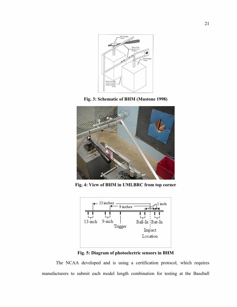
September 1999 (NCAA 1999). The procedure uses the Baum Hitting Machine (BHM),
Fig. 3, which uniquely swings both the baseball bat and the baseball to the impact of the
two objects. During this process, the machine measures the speeds of the baseball bat
and baseball just prior to impact as well as the batted-ball speed using pairs of high-speed
photoelectric sensors shown in the diagram in Fig. 5. The use of the machine can be
examined by reading the NCAA Baseball Bat Certification protocol. Pertinent excerpts
of the protocol are included in Appendix A. See Appendix B, a portion of the patent for
the BHM, for more details on the way in which the BHM functions. Datasheets printed
for each hit in the BHM, record, in hardcopy format, all of the data from each test hit. A
sample datasheet can be viewed in Appendix C.
21
Fig. 3: Schematic of BHM (Mustone 1998)
Fig. 4: View of BHM in UMLBRC from top corner
Fig. 5: Diagram of photoelectric sensors in BHM
The NCAA developed and is using a certification protocol, which requires
manufacturers to submit each model length combination for testing at the Baseball
22
Research Center within the University of Massachusetts Lowell. The protocol requires
the bat to be hit using the BHM at set speeds of 70±2 mph for a Ball-In speed and 66±1
mph for a Bat-In speed at the 6-inch location, where the ball-in speed is the velocity of
the baseball prior to impact measured across the pair of Ball-In sensors in Fig. 5, and the
bat-in speed is the velocity of the bat prior to impact as measured across the pair of Bat-
In sensors in Fig. 5. At these speeds, the impact occurs, and the exit velocity of the
baseball is measured the 9-inch and 13-inch locations shown in Fig. 5. Using the same
rotational velocity, the other bands in increments of a half-an-inch are hit to isolate the
sweet spot of the bat.
3.1.1 Pre-Testing Bat Preparation
Many physical properties of the bats are measured prior to a bat being loaded into
the BHM for performance testing. This process is called the profiling of the bat.
Included among these properties are the length, weight, and center of gravity.
Additionally, diameter measurements are taken at the 3-, 4-, 5-, 6-, 7-, 8-, and 9-inch
locations and two more diameter measurements made in the handle region of the bat
located at 23.5 and 27.625 inches from the barrel end. All of the diameter-measurement
locations are marked using an apparatus with v-shaped slots and permanent markers to
draw rings around the bat. This apparatus, called the profiling station, is shown in Fig. 6.
After the rings are drawn on the bat, a dial caliper is used to measure the diameter to the
nearest 0.001-inch. The length measurement is performed on the profiling station using a
yardstick with increments of a 1/16-inch and a carpenter’s square resting against the knob
to identify the end. This process is shown in Fig. 7. The weight measurements are made
using an Ohaus Navigator Scale, shown in Fig. 8, accurate to the nearest 0.005 oz. The

23
center of gravity location is determined by balancing the bat on a large section of angle
iron. That location is then marked with a circle that has diagonal quadrants shaded. The
balancing and marking processes are presented in Fig. 9. After the bat is marked
appropriately, the center of gravity location is identified by measuring the position of that
mark from the tip of the bat using the profiling station apparatus and the same yardstick
with 1/16-inch increments. The last two measurements taken during the bat profiling
process are used to calculate the mass moment of inertia (MOI). For this calculation, the
additional properties needed are the period of the bat when it is swung in a pendulum
setup. Also, for the particular setup located in the Baseball Research Center, the bat is
supported by its knob in a special device shown in Fig. 10. The distance from the tip of
the knob to the center of the axis of rotation is measured using a small ruler. This
distance is required to calculate the distance from the pivot to the center of mass of the
system and apply the parallel axis theorem to the MOI calculated about the pivot to the
different locations on the bat. The basic equation used to calculate the MOI is shown in
Eq. 2 (Lerner 1996, 309). Appendix D includes the complete set of equations used to
account for the MOI of the apparatus and the parallel axis theorem.
2
2
4πτ gMDI ⋅⋅⋅= Eq. 2
where: I is MOI, Mass Moment of Inertia [in.2-oz.]
τ is period of oscillation [s2]
D is distance from pivot to center of gravity of bat and fixture [in.]
M is mass of bat and fixture [oz.]
g is acceleration of gravity (386.4 in./s2)

24
Fig. 6: Profiling station
Fig. 7: Use of carpenter's square with profiling station

25
Fig. 8: Ohaus scale measuring weight of a baseball
Fig. 9: Balancing of bats on angle iron to determine CG
26
Fig. 10: MOI fixture showing both wood and aluminum bats
3.2 Procedures Used for Determining the Effect of Use on Aluminum Baseball Bat
Performance
Aluminum bats are used in many different leagues and by people of all different
ages. One of the main reasons for aluminum bats being used by so many different people
is that these bats have a much longer life than their traditional counterpart, the wood bat.
Because a single aluminum bat may be used by a number of players for an entire baseball
season or more, the bats experience a large number of hits, potentially numbering in the
thousands, before the bat would be considered unusable due to excessive denting or
cracking. A legal baseball bat in the NCAA must be able to have a ring with an inner
diameter of 2.657 inches pass over its entire length and be free of dents for it to be able to
be used in a game. Therefore, if a bat dents, this denting may easily cause a section of
the bat’s diameter to increase and subsequently fail the ring test. Additionally, denting of
this nature can be identified by touch. Because many aluminum baseball bats are

27
manufactured right at the extreme limit of maximum allowable barrel diameter, any
deformation of the barrel is likely to be identified as exceeding the barrel outer diameter
specification. Any form of cracking of the bat will also deem the bat unusable.
Generally, a crack in an aluminum bat would be found in the barrel end and orientated in
the longitudinal direction. The cracks may start off very small and grow as more hits are
taken with the bat.
Based on this presented scenario, it was decided to test several aluminum bats
through their full life spans. During the testing for this thesis, the aluminum bats were
generally tested until the cracking or denting was judged to be excessive. This testing
would take into consideration the bat being used up to the point that any bat would
realistically experience in the field. If a player, coach or umpire were to be very critical
of the bat’s surface, then a bat would have experienced only a portion of the use involved
in the entire testing process of the bat in the lab. Otherwise, the bat could be potentially
used further after some identifiable cracking or more significant denting, but still not to
the extent investigated during the testing incorporated during this thesis.
3.2.1 General Aluminum Bat Testing Procedure
In a normal NCAA aluminum bat certification, a bat will be tested at the 6.0-inch
band and then the 5.0- and 7.0-inch bands respectively. Following these locations, as
many other locations are hit to determine with confidence the sweet spot of the bat. The
certification protocol requires that the sweet spot as well as a ½-inch to either side of that
location be hit to isolate the sweet spot. As many hits as necessary are taken to obtain
five valid at each band location. Three criteria must be satisfied for a hit to be considered
valid. First, the Ball-In and Bat-In velocities must be within the required tolerances
28
described in Section 3.1, 70±2 mph and 66±1 mph, respectively. Second, the target of
the ball trajectory must fall within the either the Per Per, Per Right, Per Left, Per High, or
Per Low region as are specified in Section 2.3. Third, the velocity obtained from the
Ohler speed gates, positioned six feet from the impact and shown in Fig. 11, must read a
slower velocity than either the 9-inch or 13-inch batted-ball speed measurements. For a
more detailed description of the requirements of a valid hit, refer to Appendix E, the
NCAA certification protocol. If the ball-exit velocity averages indicate that the sweet
spot will be at either the 5.5-inch or 6.5-inch band, by means of the higher performing
position the 5.0-inch or the 7.0-inch position respectively, then that position will be
tested. If that band turns up to be the sweet spot location, by it having a higher average
Ball Exit Speed Ratio (BESR) value than the location a ½-inch to either side, then the test
is considered complete. If the 6.0-inch band is still the higher performing location, then
the other band is hit to either result in it being the sweet spot or showing that the sweet
spot is indeed the 6.0-inch band. For a bat to complete certification, the sweet spot must
be hit as well as a ½-inch to either side -- even if the sweet spot falls outside the 5-inch to
7-inch region. During the process of hitting the different band locations on the bat, the
bat is rotated randomly in the grip in order to hit the different surfaces on the bat. When
an aluminum bat is used in practice or in a game, the player would generally hit different
surfaces throughout the use of the bat, because there is no particular orientation identified
in the labeling or painting of aluminum baseball bats.

29
Fig. 11: Check cell speed gate for BHM
3.2.2 All-in-Machine Method
The first method for determining the effect on performance as a result of the use
of the baseball bat was conducted entirely in the Baum Hitting Machine and consisted of
performing consecutive certifications of an individual bat. Three bats were used for this
segment of the testing, and they are listed in Table 1. Each of these bats was tested with
slight differences in their procedures. However in all three cases, the bats were tested
through multiple consecutive certification cycles. Unlike the normal NCAA certification
process, each certification cycle always included five valid hits at each of the normal five
bands on the bat (i.e. the 5.0-, 5.5-, 6.0-, 6.5- and 7.0-inch bands.) For relative
comparative purposes, it was necessary to test the same locations each time regardless of
where the sweet spot was located for that particular certification cycle. This same-
location requirement was used because the purpose of each hit had two outcomes:
measurement of performance and use of the bat at the particular locations being hit.
30
Performance measurements were determined as a result of each single certification cycle.
Additionally, with some of the test bats, other measurements were taken. These
additional measurements included surface deformation, hardness and microscopy
measurements to help identify changes and trends in the behavior of the material.
Table 1: Bats used in All-In-Machine Test
Bat ID Length MaterialPD01 33” C405 AlPD02 33” C555 AlPD03 33” C405 Al
This method of testing an aluminum bat exposed the bat to use while the
performance measurement testing was being conducted in the BHM. The potential
workhardening of the bat takes place as the bat’s surface is dented which can result from
each hit. Each hit in the machine is a full-contact, line-drive hit. When a bat is used in
the game of baseball, it is hit on many locations on the bat as well as with many different
angles and intensities. During the portions of the test in the machine, the bat’s surface is
only hit on the narrow 2-inch wide band, which generally encompasses the sweet spot.
For this reason, the bat presumably requires fewer total hits than if the entire barrel of the
bat were being hit. This test method also constitutes the most controlled test, because
each hit is performed under the same environmental conditions, at the same intensity, and
with clean and practically new Rawlings R1NCAA baseballs.
Sections 3.2.2.1, 3.2.2.2 and 3.2.2.3 discuss the specific details of each of the tests
performed entirely in the BHM. Though there were many similarities among the tests,
each was performed with a few slight differences. PD01 was the first bat to be tested,
and although the testing went well, it was spread out over an extensive period of time.

31
Additionally, it was difficult to predict what would happen as the bat was hit repeatedly.
Therefore, only the normal NCAA certification profiling properties of the bat were
measured during the testing process. PD02, made by a different manufacturer, was the
second bat tested. After performing the testing of PD01 and analyzing the results, it was
determined that the test may be better completed if tested in a more regimented way,
therefore properties including deformation and hardness measurements were also
recorded. Because the bat was also rotated in a more regimented way, the bat’s surface
dented more severely in a much shorter time period. To remedy this severe denting,
another bat was tested, PD03, was tested under different conditions. In addition to the
PD03 being of the same manufacture and model as PD01, the bat was rotated more
evenly around the entire surface to ensure a complete test. Additionally, a similar battery
of peripheral tests was performed as were intended for the testing of PD02. The results
of the first two bats complement the testing of PD03.
3.2.2.1 Test Method for PD01
PD01 was the first bat tested to determine the effect of use on an aluminum bat.
The test of this bat’s performance was completed using much the same procedure as
would be used to test any aluminum bat in the BHM for NCAA certification. Originally,
there was only anecdotal information on any performance changes that would result from
an aluminum bat being used. Because aluminum bats are subjected to certification
testing for the NCAA when they are brand new, the performance data on the bats is only
known for the bats in their new state. A normal NCAA certification will generally have
between 25 and 40 hits taken on the bat to obtain the needed number of valid hits.
Therefore, because an aluminum bat may experience more than a thousand hits during
32
players’ use, the bat’s NCAA certification performance is known only for a fairly new
bat. When it was decided to perform tests on a baseball bat to determine the effect of its
use, it was unknown how long the bat would remain in good enough condition to
continue the testing. Additionally, it was unknown what to expect for results. Therefore,
a traditional and fairly durable aluminum bat constructed of C405 aluminum alloy was
selected to perform the tests. The performance measurements were accomplished using
the procedures described in Section 3.2.2.1.1.
3.2.2.1.1 Performance Measurement Method for PD01
To inspect the effect of use and the theory of workhardening, the testing of PD01
was performed with the intention that the bat could be repeatedly hit -- well beyond the
number of hits involved in normal performance testing. Given the available machine
time due to other priorities, the bat was initially hit through five cycles totaling 205 hits.
Before that time no aluminum bat had been tested in the BHM for more than a two
certification cycles and there was no idea how long a bat would survive. The results of
those first five certification cycles showed about a 2% increase in performance from the
first cycle to the fifth cycle. The limited data also did not show a tapering off of the
increase in performance, so it was determined that more testing would need to be
completed. Two more cycles were completed in the meantime, but resulting from a full
lab schedule the remainder of the testing pushed off the completion of the testing for
another year. The testing of PD01 was completed in July 2001, when a total of 14 more
cycles were completed. The certifications were performed identical to any other NCAA
aluminum bat certification with the only change being that all five-band locations and
only those five locations were hit, regardless of sweet spot location. Though a crack

33
formed in the barrel of the bat during cycle 14, the testing was continued to see how fast
and far the crack would propagate as well as what type of performance change would
occur with a crack in the barrel of the bat.
Different R1NCAA baseball lots were used to complete the testing, because the
testing of PD01 was spread out over such an extensive period of time. Each baseball lot
may have a different performance average and therefore has a performance value
determined for relative comparison purposes. The data from one lot of baseballs can be
compared to the testing with any other lot using a reference value. Table 2 summarizes
the comparison values concluded from the results obtained from their respective ball
certifications. To obtain the comparison, a representative sample of baseballs from each
lot is hit in the BHM with a standard 34-inch, 31.1-ounce Baum Bat at the impact
velocities of a 68-mph Bat-In at the 6-inch location and a 70-mph Ball-In. The ball lot
comparison uses the analysis procedure identified in Section 4.1.3. Table 2 identifies the
relation of the different ball lots from the lot used for the first cycle, the standard
deviation of the mean for each of these lots, and the certification cycles which were
completed using that particular baseball lot.
Table 2: Ball Lot Performance comparisons for PD01
Baseball Lot ID
Certification Cycles
Relative Velocity (mph)
Increase (mph)
Standard Deviation of Mean
R10a 1 – 5 94.994 --- 0.3195 R12b 6 – 7 95.807 0.813 0.2162 R18a 8 - 21 97.582 2.588 0.2277
34
3.2.2.2 Test Method for PD02
The testing of PD02 for the effect of use on performance was conducted in much
the same manner as PD01. Several changes were made to the test with the intention of
removing some of the unknowns that complicated the analysis of the results of PD01.
The first major change was that instead of rotating the bat randomly as was specified in
the NCAA certification protocol, PD02 would be rotated exactly ¼-turn after each hit.
This ¼-turn would allow for the specific location of the bat to be tracked from cycle to
cycle. Additionally, this turning procedure would presumably increase the rate at which
the impacted locations would be worked, and therefore, reduce the total number of hits
required to “destroy” the bat. The other major changes to the testing of PD02 included
the tracking of the surface profile of the barrel, described in Section 3.2.2.2.2, and
hardness measurements, described in Section 3.2.2.2.3. With these few changes and
additions to the testing process, the remaining portions of the performance testing of
PD02 were conducted using the same procedure as PD01.
3.2.2.2.1 Performance Measurement Method
Like PD01, the batted-ball performance of PD02 was measured using the BHM.
The procedure for hitting PD02 was the same procedure as used for hitting PD01,
explained in Section 3.2.2.1.1, except instead of randomly rotating the bat and having no
record of the actual surface hit, the bat was rotated a ¼-turn after each hit. Markings
were drawn on the end of the bat to be sure that each ¼-turn was lined up so that every
fifth hit was being hit on the same surface. This rotation was intended to work the
specific locations on the bat’s surface uniformly and quickly.

35
3.2.2.2.2 Deformation Change Results
The primary mode of change being investigated during the effect-of-use portion
of this thesis is the result of a material change, specifically the result of working the
aluminum surface to potentially become harder. As discussed in the Section 2.2.1,
workhardening is a process by which the material properties change as a result of plastic
deformation. Therefore, during the testing of PD02, the deformation in the impacted
region of the bat was tracked between each certification cycle of hitting. The data were
collected using a combination of diameter measurements from a dial caliper and relative
changes in the local radius from a dial indicator. The apparatus shown in Fig. 12 uses the
dial indicator to measure relative differences in radius as the bat is rotated on supports
that are not near the deformed part of the barrel of the bat.
The procedure used for measuring the change in surface profile included first
measuring the diameter on the 12-6-axis at the 5-, 6- and 7-inch locations. The 12-6-axis
refers to the diameter where the points are located at the intersection of the 5-inch band
and the 12 o’clock position and the 5-inch band and the 6 o’clock position. This
measurement allows for the determination of an initial radius. The bat was then placed in
the apparatus shown in Fig. 12. Once loaded in the apparatus and free to spin, the dial
indicator is positioned such that it is perpendicular to the surface of the bat, vertically.
The dial indicator then shows a value between 0.000 and 1.000 inches. Though this value
means nothing by itself, the difference from measurement to measurement as the bat is
rotated to each of the 12 clock positions will give a relative change in diameter. When
these changes are coupled with the absolute diameter of the 12-6 axis, the absolute local

36
radius can be very closely approximated using the calculation shown in Eq. 3. This same
process was also followed for the 6- and 7-inch bands.
Fig. 12: Surface deformation setup
ii hhhMINhhMAXDR +−−
= −
2)),(),(( 612612612 Eq. 3
where: Ri is Local Radius
D12-6 is Diameter across 12-6-axis for Band
hi is Local Height using Dial Indicator (measured value – MIN(h12,h6))
i is Clock Position
3.2.2.2.3 Process for Measuring Hardness
Because the change in performance, resulting from use, is based on a theory that
the surface of the bat workhardens, measuring the hardness can help to investigate the
phenomenon. A Rockwell hardness tester is a common way of measuring material
hardness. Instron® manufactures and loaned to the lab the digital Series 2000 unit in the
UMLBRC, shown in Fig. 13, used for the measurements made as part of this thesis.
Rockwell hardness testers use steel ball bearings or diamond tips to generate a depression
37
in the surface. Then based on the load setting, the type of tip and the depth of depression,
the device determines the hardness on a scale developed for hardness measurements.
Specifically for aluminum alloys the Rockwell B, HRB, scale is applied, which uses a
1/16” diameter steel ball bearing as the indenter and a 10 kgf minor load with a 100 kgf
major load.
In an HRB scale test, the hardness is based on a calculation using the depth of
indentation in combination with the load applied and the size of indenter. The depth of
indentation is the distance traveled after the minor load, 10 kgf, having been applied and
the major load, 100 kgf, being applied. The equation used for calculating the hardness is
presented in Eq. 4 (ASTM 2002). The test of Rockwell Hardness is presented in full in
the ASTM standard E18 (ASTM 2002).
][
][][
)00008.0()()(
130in
inMinorLoadinMajorLoad DOIDOIHRB
−−= Eq. 4
where: HRB is Rockwell Hardness B Scale Number
DOIMajor Load[in] is Depth of Indentation from Major Load - permanent
DOIMinor Load[in] is Depth of Indentation from Minor Load

38
Fig. 13: Rockwell hardness tester
The hardness tests on PD02 were performed using the Instron® Rockwell
Hardness tester shown in Fig. 13. The bat was supported on a v-shaped anvil because of
the bat’s cylindrical shape. This support allows the bat to be centered under the indenter
during the test. The handle of the bat was supported by the test operator prior to and
during the test to balance the bat. Because the bat’s shape, more specifically the taper
when moving from the barrel to the throat of the bat, holding the bat so that it does not
move during the test is very difficult. Small amounts of rocking of the bat can affect the
calculation made by the Rockwell hardness tester, because the movement of the bat
would then be significant in comparison to the indentation distance. For a hardness of
HRB 95, the indentation distance between the minor and major loading is 0.0028 inches
as calculated using Eq. 4.

39
3.2.2.3 Test Method for PD03
PD03 was the third and last bat to be tested entirely in the Baum Hitting Machine.
Several test conditions were modified because of the results obtained from testing PD01
and PD02. Some of the modifications to the test were additions made between or after
certification cycles. The measurements included tracking the change in the contour of the
barrel of the bat using a setup devised specifically for this test and the Rockwell hardness
of the bat’s surface. At the end of the entire test, a compilation of microscopy was also
completed to get a more thorough understanding of the changes in the microstructure of
the aluminum in the barrel of the bat.
3.2.2.3.1 Performance Measurement Method
Like PD01 and PD02, the batted-ball performance of PD03 was measured using
the BHM. The procedure of hitting PD03 was the same as the procedure for hitting
PD02, explained in Section 3.2.2.2.1. Instead of randomly rotating the bat or rotating
only a ¼-turn the bat was incremented into 12 clock positions evenly spaced around the
barrel. PD03 was then rotated randomly among these specific locations, but limited in
that each of the 12 clock positions had to be hit before the “random” selection would be
repeated. This rotation was intended to help keep the bat as round as possible during the
testing without experiencing targeting problems and measurement distortion from bat
geometry related issues that developed during the testing of PD02.
3.2.2.3.2 Deformation Change Results
The method used for measuring the change in deformation of the barrel of PD03
is the same as was discussed in Section 3.2.2.2.2.

40
3.2.2.3.3 Process for Measuring Hardness
The method used for measuring the hardness of the impacted surface of PD03 is
the same as was discussed in Section 3.2.2.2.3, except pieces of PD03 were also tested
through a Vickers microhardness test. These tests required small samples to be cut from
the barrel end of the bat, prepared, and tested in a Vickers microhardness tester made by
Akashi Company, model MVK-H2. The samples, which are smaller than a dime, were
cut from the barrel of PD03 after all of the performance and deformation tests were
completed. Two samples of each were cut from the 7½-inch, 6-inch, 4½-inch and 2-inch
locations in the vicinity of the 10 o’clock position. After being cut from the bat, the
samples were submitted to the Center for Advanced Materials where they were cleaned
up and ground flat for the testing. Further sample preparation and the testing were
completed by a lab in Korea using the procedures defined in ASTM E384 (ASTM 1989).
During the testing the load and size of indentation are measured and from these values
the Vickers hardness number is calculated using Eq. 5 (ASTM 1989).
2
4.1854d
PHV ⋅= Eq. 5
where: HV is Vickers Hardness Number
P is Load [gf]
d is Mean Diagonal of Indentation [µm]
3.2.2.3.4 Microscopy Methods
To gain a better understanding of the actual changes in the metal around the
impacted region of the PD03’s surface, some microscopy analysis was performed.
Because the goal of this analysis is to determine the change in the structure and the

41
analysis requires cutting the bat apart, all the cutting was completed after the bat had been
cycled through the entire hitting process. For comparison of non-impacted regions to
impacted regions, it was desired that four samples would be retrieved from the 6-inch
band to represent the totally impacted region and then four more samples from the 2-inch
band where no impacts were made. One sample from each band was cut from the 6, 7,
11, and 12 o’clock positions using a band saw. Then each sample had to be sanded and
polished prior to being sent to the Center for Advanced Materials at the University of
Massachusetts Lowell for the Transmission Electron Microscope (TEM), shown in Fig.
14, to be used by their trained personnel. The personnel performed additional cutting and
polishing that was necessary for a microscopy analysis to be performed. Additionally,
the personnel performed the data analysis, which used image processing software to
interpret the results for any quantitative material change.

42
Fig. 14: TEM at Center for Advanced Materials
Fig. 15: AFM at Center for Advanced Materials
43
3.2.3 Field Use Methods
The other method, which was implemented to determine the performance changes
of an aluminum bat while it is being used, incorporated a combination of bat certification
cycles and field-testing. The field-testing was performed by the UMass Lowell varsity
baseball team during their team practices. The bats selected for this test, PD04 and
PD05, were similar to those, 33-inch long aluminum-alloy bats, used in the All-In-
Machine method described in Section 3.2.2. The bats were first tested for their
performances in the BHM using the same procedure as identified in Section 3.2.2.3.1,
except the condition was put in place that the sweet spot had to be isolated in addition to
the normal five bands being hit. Then the bats were hit during batting practice by a
variety of college level players and generally pitched by the batting coach.
3.2.3.1 Test Method for PD04
PD04 was first tested in the BHM, as described in Section 3.2.3, and then sent out
for field-testing, described in Section 3.2.3.1.1, to be completed. After 100 to 400 hits,
the bat was returned to the UMLBRC for surface profile measurements to be completed
according to the procedure described in Section 3.2.2.3.2. It then went back to the field
for another round of hits by the team. The bat was then again, measured in the lab for its
surface contour profile, and then put through the certification process in the BHM, using
the same procedure as was used for the initial testing. PD04 was then subjected to
another cycle of field testing. This process continued for a total of seven BHM
certification cycles.
44
3.2.3.1.1 Test Method for Field Testing
The field testing of PD04 consisted of batting-practice hits in either an indoor or
outdoor batting cage with a selection of used NCAA baseballs supplied to the baseball
team by the UMLBRC. The test began with the accumulation of 100 hits per session
with two sessions of hitting between each certification cycle in the BHM. Later in the
testing, after certification cycle number 6, the target of 100 hits per session was increased
to 200 hits per session. Each pitch to the college batters was recorded as a good hit, a bad
hit, or a ground-ball/pop-up -- depending on the level and type of contact that the bat
made with the ball. A bad hit meant that it was a hit off either the tip of the bat or on the
throat or handle. Because the person marking the quality of the hit could not be
positioned directly behind the plate, the quality was judged generally based on a
combination of sight and sound. When there is the bright “ping” sound, the impact was
probably near the 6-inch location. A sound more like a “thunk” would imply that the
impact took place nearer the end of the barrel or near the handle. Pop-ups and ground
balls were judged in much the same way. These hits, although, are much easier to judge
using visual identification techniques. Each of these off target hits was not counted
towards the total, because either they were not being hit on the tested region of the bat or
they would be of little impact-force magnitude.
3.2.3.2 Test Method for PD05
PD05 was exposed to normal batting-practice use for the second half of the
UMass Lowell baseball team’s 2002 season. The bat was first tested in the BHM. In
addition to hitting the normal five locations the locations ±½-inch and ±1-inch of the
sweet spot were added to the hitting locations, thereby giving more information for
45
analysis, because only two certification cycles were to be performed on the bat. After
being tested in the BHM, the baseball team hit PD05 for about a half of their season.
During this time and unlike the use of PD04, the use of PD05 was not able to be
monitored. The bat was exposed to the normal uses of an aluminum bat by a college
baseball team except that PD05 was not used in any official baseball games. After being
used for half of the UMass Lowell baseball team’s season, PD05 was returned to the
UMLBRC to be tested using the same procedure as it was initially.
3.3 Procedures Used for Determining the Effect of Moisture Content on Wood
Baseball Bat Performance
Moisture content is a critical property of wood. Many physical properties of
wood are a consequence of the moisture content. One of these physical properties is the
weight of the wood. Moisture content by definition is directly related to the weight of the
water contained in the piece of wood. The definition of moisture content is the weight of
the water in the wood divided by the weight of the wood when completely dry, then times
100%. Strength and modulus are also physical properties which are affected by moisture
content. Two test methods were developed to investigate the effect of moisture content
on wood baseball bat performance, because this effect exists and because of the way in
which bats are selected and used by baseball players. Both methods used the same
humidification process, explained in Section 3.3.2, and the same testing process,
described in Section 3.3.3. The first method used a selection of bats of equal weight.
Half of the bats were stored at lab conditions, while the other half were stored in a
humidity chamber. The second method used a selection of the same bats each being hit

46
twice, one time after being stored in the lab conditions and the other time being hit after
having been stored in the humidity chamber.
3.3.1 General Wood Bat Testing Procedure
Wood bats are tested in a slightly different manner than aluminum bats, described
in Section 3.2.1, for the sole purpose of improving their potential of surviving the entire
test. Wood bats are known to be more prone to breaking than their aluminum
counterparts. Because each hit in the BHM is full contact and the grip, which holds the
handle of the bat, is rigid even after the hit has taken place, wood bats often survive no
longer than 25 hits in the BHM. Therefore, using the same procedure to test wood bats as
is used to test aluminum bats would rarely yield a complete test. Two primary alterations
are made to the aluminum bat protocol. The order of the positions being hit and the
number of hits at each position are slightly revised and explained in the next paragraph.
Secondly, the bat handle is wrapped with tape before being loaded into the grip. These
alterations improve the survival of wood bats for testing, and do not compromise the
performance measurements.
During the testing process for wood bats, the positions are hit in a slightly
different order than for aluminum bats; because wood bats are more likely to break when
hit at a location other than the sweet spot. Additionally, the number of valid hits required
at each location is reduced from five to three with the exception of the sweet spot.
Therefore, a wood bat is hit first at the 6-inch position for three valid hits. Then the bat is
hit at the 6.5-inch position, for three valid hits. Then the 5.5-inch position is hit. If, after
three hits, the value of the 6.0-inch position is greater than either side, two more hits are
taken at the 6.0-inch location, otherwise the location which is greatest has two additional

47
hits taken. Because, in this case, the sweet spot has not been isolated, three hits are
required at the ½-inch location to the other side of the current greatest value. If by
chance this location is again greater than the previous, then two more valid hits are
required at that location and three valid hits at the ½-inch to its side. This process would
continue as necessary, though the sweet spot this far removed from the 6-inch location is
highly unusual.
When a wood bat cracks as the result of a hit, the crack will generally begin near
or at the thinnest part of the handle. In the BHM, as well as by a batter, the bat is gripped
almost directly behind this point. In the BHM, the grip is very unforgiving to the
vibrations of the bat after the impact is completed. Therefore, for durability purposes, the
handle of the bat is wrapped with a combination of strapping tape and tongue depressors
shown in Fig. 16. This modification increases the stiffness of the bat. However, the
testing of several bats with and without the reinforcement showed no change in batted-
ball performance. The reinforcement of the bat’s handle is done by wrapping the bat with
a layer of strapping tape from about five inches to about 15 inches from the knob. Then
two tongue depressors are positioned on either side of the handle while the bat is
positioned label up and starting about five inches from the knob. Next a tight layer of
strapping tape is applied to secure the tongue depressors in position. The tape must be
continuous as to not allow a weak point for a crack to form. Therefore, the strapping tape
is normally applied at about 45o, allowing for a continuous double layer of tape over the
entire region where breakage is likely to occur.

48
Fig. 16: Wrapping of handle of wood bat for reinforcement
3.3.2 Humidification Process
For a wood bat to experience an increase in moisture content, the environmental
conditions must be set to a condition for a higher equilibrium moisture content. This
scenario requires the bat to be placed in an environment of higher relative humidity if
maintaining the same temperature. For this purpose, the humidity chamber, shown in
Fig. 17, was constructed. The chamber’s walls, floor, and ceiling were cut from a 3/16-
inch Plexiglas sheet, while the doors and front panel were cut from ¼-inch thick
Plexiglas. The doors were sealed with a strip of plastic tubing to help retain the moisture
inside the chamber. A Holmes Accuset Humidifier, model number HM-5700, as shown
in Fig. 17, was then placed in the bottom of the chamber to humidify the air inside the
chamber as necessary. The humidifier can be set to regulate the humidity and to maintain

49
a relative humidity from 30% to 90% in increments of 5%. Because the chamber is a
very small volume in comparison to a room, the humidifier maintains the desired
humidity by over humidifying the chamber to a point of temporary saturation and then
allows the humidity to seep out at a slow rate. The humidifier again adds moisture in the
chamber after the relative humidity in the chamber falls below the desired level. The
chamber, which stands eight feet tall and has base dimensions of 15 inches by 18 inches,
is designed to hold 12 bats but could be used to store as many as 36 bats if the bats were
stored on two levels.
Fig. 17: Humidity chamber (left) and humidifier (right)
The bats used for the effect-of-moisture-content tests were stored in the chamber
for a time period of about one week. During this period, the humidity chamber was set to
have a humidity of 85% at the normal lab temperature of 70o F. Because the humidifier
overshoots the intended RH set point, the actual RH setting to which the bats were
exposed varied from about 83% RH to saturation. The average relative humidity in the

50
chamber was about 88% on average. The variations in moisture content did not play a
significant role in the final moisture absorption over the time period, because the
absorption of moisture into wood is slow. In the one-week period and adjusting from the
normal lab conditions of 50% RH and 70oF, considered to be the dry sample, to 88% RH
at the same temperature, considered to be the moist sample, a typical professional-grade
wood bat gained about an ounce of weight.
3.3.3 Moisture Content Testing Process
The performance testing of bats during the effect-of-moisture-content tests all
used the same process. The actual method of testing the bats in the BHM was the same
as for a typical wood bat as described in Section 3.3.1. The only differences in the
complete testing process existed in the measurements made prior to and after the BHM
testing. The status of each bat was divided into two categories, the dry bat, a bat stored
for at least one week in the normal lab conditions, and the moist bat, a bat stored in the
humidity chamber at an elevated humidity for at least a one week. Each bat, whether dry
or moist, was tested using the same procedure. Ideally, the entire measurement and
testing process of the moist bats would take less than three hours to ensure that the
moisture content of the bat would remain essentially constant during the procedure,
because the BHM testing is performed at lab conditions.
The testing process followed a sequence of steps prior to and after the
performance testing in the BHM. A sample of the worksheet used to keep track of the
time each task was carried out and the results of some of the measurements is located in
Appendix F. The process began with removing the bat from the humidity chamber if it
was a test of a moist bat. Then the bat being tested was profiled according to the normal

51
bat profiling procedure as described in Section 3.1.1. After being profiled, the bat was
tested for moisture content. These measurements were performed in two ways. One way
used a digital moisture meter, the Pinless mini-Scanner L manufactured by Lignomat
USA Ltd. Using this instrument and its setting (6) used for ash and other hardwoods, the
leading edge of the sensor pad was placed on the two-inch-band location and then
scanned to the eight-inch-band location. The highest and lowest readings that were read
off the digital display were then recorded on the worksheet. This process was performed
on four sides of the bat. Side one was designated to be the side on which the logo is
located. Then the other three sides were each 90 degrees offset clockwise looking down
the bat from the handle end. Following these moisture-content measurements, a
Delmhourst Lite moisture meter, which uses resistance between two prongs penetrating
the wood to perform the measurement, was used to obtain another moisture-content
value. The location of this measurement was in the logo of the bat. After the moisture-
content measurements were made, the bat was reweighed to be sure that the actual test
weight of the bat would be known. The bat was then wrapped with strapping tape and
tongue depressors and tested for performance in the BHM according to the procedures
described in Section 3.3.1. The baseballs used during the testing were 2002 Major
League baseballs. After the testing in the hitting machine, the strapping tape was
removed and the bat was inspected for cracks. Then each of the procedures completed
prior to the bat’s testing were completed again in the reverse order.
3.3.4 Bat Selection Process
The bats used for the effect-of-moisture-content tests were supplied by Hoosier
Bat Company. Because wood bats often break during testing in the BHM, the HB235 bat

52
model was selected. This model was selected because it is often more durable as a result
of having a relatively thick handle. Because the results of the effect of moisture content
on wood baseball bat performance would be of the greatest significance to MLB, the
length and weights of the bats were chosen to represent typical Major League bat
selections.
Thirty-four inches was selected to be the nominal length of the bats used in the
tests. The weights were chosen based on three criteria. Half of the bats were to be placed
in the humidity chamber and during the span of about a week gain one ounce. Therefore,
for the Same Weight Method, Section 3.3.5, half of the bats had to be one ounce lighter
than the other half, because of the 1-ounce weight gain in the humidity chamber. The
second criterion for choosing the bat weights was based on Major League player bat
selection. Many Major League baseball players will swing a bat that is between (–1) and
(–3), relating to the bat’s length in inches being subtracted from the weight in ounces.
The third criterion was focused on durability. Wood bats often break when exposed to
the rigorous testing in the BHM as for a single certification process. The bats used for
the Same Bat Method, Section 3.3.6, were to be exposed to two certification style tests.
Therefore, durability is very important, because heavier bats are generally more durable
in the BHM and using the other criteria, the bats selected for testing nominally consisted
half of 31.5-ounce and half of 32.5-ounce.
3.3.5 Same Weight Method
The Same Weight Method for determining the effect of moisture content on wood
baseball bat performance is a very direct method of identifying any effect. Because the
bats were all of very similar weights and MOIs, they would be swung at the same speed

53
by and feel very similar to a player when at bat. The drawback to this test is that a
different sample of bats is used for the testing at each of the moisture contents, and
therefore, because wood has a wide range of properties, the sampling of bats had to be
such that it would give a statistically acceptable size for the comparison. A ten-bat
sample of 34-inch Hoosier HB235 bats of each of the two weight classes was selected to
allow for some breakage of bats during the process and retain an acceptable sample size.
After being stored in the lab conditions for a minimum of one week, the 10 samples,
which were nominally 31.5 ounces, were profiled and placed in the humidity chamber
according to the procedures described in Sections 3.3.2 and 3.3.3. The other 10 samples,
which were nominally 32.5 ounces, were left to continue acclimating to the laboratory
conditions. After a week in the humidity chamber, each bat was removed from the
humidity chamber immediately prior to being tested. Additionally, over the same period
of time, the bats, which had been left in the lab conditions, were also tested using the
same processes. After each of the 20 bats was tested, each individual bat, if unbroken
during this test, was placed in the opposite location from how it was stored in preparation
for this test. This new storage was in preparation for the bats being tested according to
the Same Bat Method, as described in Section 3.3.6.
3.3.6 Same Bat Method
Unlike, the Same Weight Method, described in Section 3.3.5, the Same Bat
Method is less dependent on a large sample to account for the variations inherent in
wood. The drawback of this method is the difficulty that comes from calculating an
adjustment in performance because the bat weights and MOIs are different at different
moisture contents and therefore cannot be swung at the same speed. During the testing

54
for this method, the bats which had been 31.5 ounces and been humidified to a weight of
32.5 ounces were allowed to air dry in the lab for a week or more to return to their 31.5-
ounce weight. The bats which weighted 32.5 ounces stored at lab conditions and tested at
that weight were placed in the humidity chamber for a week and then tested at a weight
of around 33.5 ounce. The profiling, moisture content measurements and testing were all
completed according to the procedures in Section 3.3.3. Only the bats, which remained
unbroken through the Same-Weight-Method tests, were included in this method.
55
4 ANALYSIS METHODOLOGY
This chapter identifies and explains the general techniques used for analyzing the
tests described in Chapter 3. Section 4.1 identifies the methods used to generate the data
points. Each data point, depending on the test, may represent the average of the raw data
collected or a calculation taking into consideration variables that could not be eliminated
entirely during the test. Section 4.2 identifies the statistical methods used to prove or
disprove the null hypothesis that there is no effect of use on aluminum bat performance
or effect of moisture content to wood bat performance. The use of the analysis methods
presented in this section will allow conclusions to be drawn from the results.
4.1 Data and Data Points
Varying degrees of data analysis will be used to interpret the results of the testing
performed for this thesis. In most cases, several methods will be presented to show that
although conclusions may vary slightly, the same general trends exist when using
different methods. Initially in some cases, the raw batted-ball velocity data, as described
in Section 4.1.1, will be used. Though these raw data can be the most straightforward
presentation of the data, variability of other factors may not be considered. Some of
these factors to be considered are the slight variations of the ball-in and bat-in velocities.
Additionally, the manufacturing of the baseballs used in the test may introduce slight
variations. Another factor, although minimized, can be variation of the calibration of the
BHM. These factors may be small, but the potential differences trying to be detected
56
may also be small. Therefore, several different methods have been used to examine the
data to account for these factors.
Several calculations and procedures are performed during the data analysis phase
of a bat certification for the NCAA. The use of a ball exit speed ratio (BESR), a
dimensionless number, can help to consider variability of the inbound velocities of the
bat and ball. The details of the BESR are presented in Section 4.1.2. Section 4.1.3
describes a method by which variation in the performance of the baseballs used in the
testing can be considered when determining the bat performance. Additionally, the
average of individual datum is used to calculate the performance of the bat. The different
combinations of data used are presented in Section 4.1.5. After applying these
calculations and procedures to the raw data, the investigator can have confidence in the
resulting trends.
4.1.1 Raw Batted-Ball Velocity Data
The raw data of each hit in the BHM are collected with a data acquisition
program, written in Testpoint®. An example of the datasheet is in Appendix C. Included
among the data on this printout are the measured inbound ball and bat velocities and the
ball exit velocity as measured across the 9- to 10-inch and 13- to 14-inch optic beams.
Additionally included are properties of the bat and ball used in the test. When referring
to the analysis consisting of raw data, the data used off the sheet will be the higher of the
two exit velocities of the baseball. Choosing the higher exit velocity is the basis of the
performance measurement as used in the NCAA certification protocol. In the BESR
calculation, the measured bat-in and ball-in velocities will be used directly from the
datasheet values.

57
4.1.2 Ball Exit Speed Ratio (BESR)
The performance data collected during each test hit in the BHM consists of the
batted-ball, bat-in, and ball-in velocities as well as other properties of the bat and the ball
used in the test. Within the NCAA certification protocol, the maximum of the two
batted-ball velocity measurements as well as the bat-in and ball-in velocities combine,
using Eq. 6 and Eq. 7, to calculate the BESR value. This value helps to adjust for the
slight variations that are allowed and unavoidable form the bat-in and ball-in velocities
during the testing.
( )
( )vV
vVvBESR
+
−−=
∗
2 Eq. 6
where: BESR is Ball Exit Speed Ratio
v* is Batted-ball velocity in mph
v is Ball-in velocity in mph
V is Bat-in velocity at 6-inch location in mph (see Eq. 7)
)375.5()375.11(Ll
lVV C −−−= Eq. 7
where: VC is Bat-in velocity as measured at impact location in mph
l is Bat length in inches
L is Location of impact in inches (e.g. 5.0-inch or 6.5-inch)
The BESR value was developed by M.M. Carroll (Carroll 2000) to relate the
inbound baseball and bat velocities to the exit velocities of the baseball and bat. The
laws of physics conclude that the BESR, a function of mass ratio and coefficient of
restitution (COR), remains essentially constant for any combined sum of inbound

58
baseball and bat velocities. Carroll uses two physical models to generate the BESR. The
first model is a particle model, in which the law of conservation of momentum, Eq. 8, the
definition of COR, Eq. 9, and a ball/bat mass ratio, Eq. 10, are used to solve for the ball
exit velocity, vb´, in terms of the inbound velocities, the COR, and the mass ratio, Eq. 11.
The sign in front of Vt in Eq. 9 is positive because in reality, the bat does not reverse
direction. Therefore, throughout the BESR formulation, the exit direction of the ball
reverses after impact while the exit direction of the bat continues in the same direction as
it entered.
bbttbbtt vmVMvmVM −=′+′ Eq. 8
where: Mt is mass of bat
Vt′ is exit velocity of bat
Vt is inbound velocity of bat
mb is mass of baseball
vb′ is exit velocity of baseball
vb is inbound velocity of baseball
)( tbtb VveVv +=′−′ Eq. 9
where: e is Coefficient of Restitution
t
b
Mm
=µ Eq. 10
where: µ is ball/bat mass ratio
btb veVevµµ
µ +−+
++=′
111 Eq. 11

59
The coefficients of the inbound velocities in Eq. 11 differ by a numerical value of
one. Therefore, the BESR was decided to be numerically halfway between these two
coefficients. Alan Nathan (Nathan 2001) separately developed a “collision efficiency”
which is equal to the coefficient of the inbound velocity of the baseball in Eq. 11. For
Carroll’s rigid-particle model, the exit velocity of the baseball is calculated from the
BESR and the inbound velocities of the baseball and bat using Eq. 12.
( ) ( ) btb vVv ⋅−+⋅+=′ 21
21 κκ Eq. 12
where: )1(2
21µ
µκ+
−+= e is BESR Eq. 13
Because the baseball and bat are not particles, the entire mass of the bat is not
significant during the impact. Therefore, Carroll used a rigid body model of the collision
to account for the fact that the bat is being swung and is not a particle. Using the
conservation of angular momentum in place of linear momentum and the translational
inbound and exit velocities at the point of contact of the bat, VCt and VCt′ respectively,
Carroll is able to write Eq. 8 with Mt replaced by Mt*, an effective bat mass given by Eq.
14 and Vt and Vt′ replaced by VCt and VCt′, respectively. Replacing Mt with Mt* from the
equations used in the particle-model and consequently using an effective bat/ball mass
ratio, µ*, defined in Eq. 15, in place of µ, the formula for the BESR can be calculated for
the rigid-body model. The formula for the exit velocity of the baseball in terms of the
inbound velocities and the BESR is shown in Eq. 16 and by the relationships to Eq. 15,
Eq. 17, and Eq. 18.

60
2*xIM t = Eq. 14
where: Mt* is effective ball/bat mass ratio
I is mass moment of inertia of bat about the axis of rotation
x is distance from axis of rotation to point of contact with the ball
Ixm
Mm b
t
b2
** ==µ Eq. 15
where: µ* is effective ball/bat mass ratio
( ) ( ) bctb vVv ⋅−+⋅+=′ 21
21 κκ Eq. 16
where: *)1(2
*21µ
µκ+
−+= e is BESR Eq. 17
xVCt ⋅= ω is inbound velocity of bat at contact point with the ball Eq. 18
where: ω is inbound angular velocity of the bat
x is distance from axis of rotation to the point of contact
Because the BESR value is conceptually more difficult to relate to than a batted-
ball velocity, the results of the testing for this thesis have been converted back into
velocities for the presentation of the data. Again all of the testing was performed with the
same required ranges of bat-in and ball-in velocities. Therefore, using the target
velocities, 66-mph bat-in and 70-mph ball-in, and Eq. 6, Eq. 19 can be used to back
calculate and obtain adjusted batted-ball velocities, v**.
2))7066(*(** −+= BESRv [mph] Eq. 19
61
4.1.3 Adjustments for Ball Lot Certifications
Baseballs are used for the comparative testing of one bat to another. Though
these baseballs are manufactured with relatively good repeatability, the performance of
individual baseballs within a shipment can vary. The average performance of the
baseballs may also vary from shipment to shipment. A shipment of baseballs may
become a lot or be broken up into multiple lots based on the size of the shipment and the
number of baseballs required for the testing schedule in the UMLBRC. Though the
variability within the shipment cannot be eliminated, averaging the performance of more
than one hit can minimize its effect. Testing a representative sample, about 10% to 15%,
from each lot using a single bat allows each lot to be compared to previous and
subsequent lots.
The Baum Bat AAAPro 34-inch 31-ounce bat is the Standard Bat used for this
baseball lot testing. According to the NCAA certification protocol, the bat is swung at 68
mph at the 6-inch location while the ball is swung into the hit at 70 mph. The faster of
the two exit velocity measurements from each valid hit are used for calculation of bat or
in this case the ball performance. This value is then added to 2.9 mph, a value first
obtained to compare the Standard Bat performance to the maximum 34-inch wood bat
performance. This value now can be used to compare any test of a bat to any other test of
a bat.
Knowing the specific performance of each baseball lot allows for adjustments to
be made to the raw data. For Example: Bat A hits a ball at 95 mph using Ball Lot A,
which had a performance of 93 mph. Bat B hits a ball at 96 mph using Ball Lot B, which
had a performance of 95 mph. Even though Bat B hits one mph faster, the performance

62
of Bat A is actually 1 mph faster because Bat A would hit 97 mph with Lot B. This 97-
mph velocity is concluded in this case by considering the difference between the
performances of the two ball lots.
The testing of each ball lot secondarily acts as a calibration of the system
accounting for any slight and unavoidable changes to the BHM. These small changes in
the measurement system may be introduced when replacing a damaged fiber-optic sensor,
or a shift of an optic by a few thousands of an inch and would be considered when the
ball-certification testing is completed, because the bat testing is completed using the same
setup. Therefore, the new ball performance acts as a lumped parameter that incorporates
any change in the lot of baseballs as well as any slight changes that may have occurred in
the experimental setup.
4.1.4 Adjustment for MOI and Swing Speed
The mass moment of inertia (MOI) is the primary property of an object that
effects the swinging of that object. During the effect-of-moisture-content tests conducted
during this thesis, the MOI of the bats becomes critical in determining the effect on the
performance. During the same-weight-method tests, the bats are of very similar weights
and MOIs, and therefore, each bat would be swung at a very similar speed by a player.
The same-bat-method tests are not as convenient, because the two tests on each bat are
performed with two different MOI conditions. Therefore, each bat would be swung in
the field with different swing speeds and, therefore, would potentially exhibit different
batted-ball performances. This subsection will discuss the methods used to account for
the variations in MOI and what adjustments were required to make the performance
comparison.
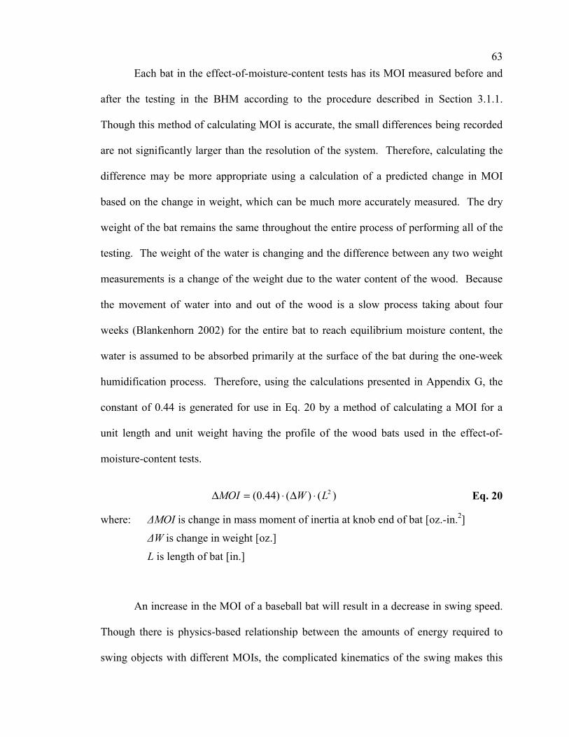
63
Each bat in the effect-of-moisture-content tests has its MOI measured before and
after the testing in the BHM according to the procedure described in Section 3.1.1.
Though this method of calculating MOI is accurate, the small differences being recorded
are not significantly larger than the resolution of the system. Therefore, calculating the
difference may be more appropriate using a calculation of a predicted change in MOI
based on the change in weight, which can be much more accurately measured. The dry
weight of the bat remains the same throughout the entire process of performing all of the
testing. The weight of the water is changing and the difference between any two weight
measurements is a change of the weight due to the water content of the wood. Because
the movement of water into and out of the wood is a slow process taking about four
weeks (Blankenhorn 2002) for the entire bat to reach equilibrium moisture content, the
water is assumed to be absorbed primarily at the surface of the bat during the one-week
humidification process. Therefore, using the calculations presented in Appendix G, the
constant of 0.44 is generated for use in Eq. 20 by a method of calculating a MOI for a
unit length and unit weight having the profile of the wood bats used in the effect-of-
moisture-content tests.
)()()44.0( 2LWMOI ⋅∆⋅=∆ Eq. 20
where: ∆MOI is change in mass moment of inertia at knob end of bat [oz.-in.2]
∆W is change in weight [oz.]
L is length of bat [in.]
An increase in the MOI of a baseball bat will result in a decrease in swing speed.
Though there is physics-based relationship between the amounts of energy required to
swing objects with different MOIs, the complicated kinematics of the swing makes this

64
very difficult to determine. Fleisig performed an experimental study measuring swing
speeds of different bats using players in a batting cage. The results of this work showed a
linear relationship between MOI and swing speed, Eq. 21 (Fleisig 2002).
)()106.6( 4 MOIVt ∆⋅⋅−=∆ − Eq. 21
where: ∆Vt is change in swing speed (bat in velocity) at 6-inch location [mph]
A change in swing speed will lead to a change in batted-ball velocity. To
determine the effect on the batted-ball velocity, a test was performed using a standard bat
in the Baum Hitting Machine. The bat was swung at several target speeds above and
below the normal 66-mph target speed. The ball was pitched with a target speed of 70
mph. A total of 50 hits were recorded. The BESR was then calculated as normal using
Eq. 6. The batted-ball velocity was then backcalculated using Eq. 19, except the 66 was
replaced with the actual measured bat-in velocity, because the bat-in velocity is the
important variable in this analysis. Fig. 18 represents these backcalculated velocities
with respect to their bat-in velocity.

65
60 62 64 66 68 70Inbound Velocity of Bat at 6-inch Location (mph)
84
86
88
90
92
94
96
Bat
ted-
Bal
l Vel
ocity
(mph
)
Fig. 18: Batted-ball velocity as a function of inbound bat velocity
The normal bat-in velocity during the testing is 66 mph. The majority of the data
points in Fig. 18 are between 62 and 66 mph. The reason for this focus is because the
moisture-content tests performed as part of this thesis compare bats that are at lab
conditions to bats with higher moisture contents. Therefore, the humidified bats are
increasing in weight and would be swung slower. The linear regression of the data in
Fig. 18 leads to the relationship between the inbound bat velocity and the batted-ball
velocity that is identified by Eq. 22. The R2 value of the data about the linear regression
is 0.611. The batted-ball velocity in Fig. 18 is adjusted for the slight variations in ball-in
velocity during this study using a very similar procedure as was developed in Eq. 19,
except no adjustments were made for the bat-in velocity.
)()839.0( tb Vv ∆⋅=′∆ Eq. 22
where: ∆v’b is change in batted-ball velocity [mph]

66
4.1.5 Combining of Data
Section 4.1.3 discussed the adjusting for the variability from lot to lot of baseballs
as well as the calibration of the machine. It also mentioned that there is variability from
baseball to baseball within a specific lot. A given baseball may have a 3-mph or more
performance difference compared to another ball in the same lot. Therefore, it is
important to limit the significance of any one individual hit. Averaging of data from five
hits across a band location or even 25 hits across the entire two-inch region of the bat that
is impacted during the testing is a good method to account for this variability.
When the performance testing is conducted, there are generally five valid hits
obtained from each location on the barrel of the bat. A wood bat may in some cases have
only three valid hits obtained from some locations, because wood bats may crack before
recording five valid hits. The average of these three to five valid batted-ball velocities is
then calculated for each location. This value will be referred to as the Average Exit
Velocity (AEV) of the band. During the effect-of-use testing, five valid hits were always
obtained for each of the same five standard locations on the aluminum bat. In these
cases, the average of the 25 batted-ball velocities will be referred to as the AEV of the
cycle. The AEV of the band and the AEV of the cycle are the ways in which trends will
be shown of how the performance of the bat is affected by the induced changes.
During the analysis of the effect-of-use of an aluminum bat, both the AEV of
band and the AEV of cycle will be included to show the consistency of the results. Only
the AEV of band will be used during the effect of moisture content tests, because during
the testing of a wood bat, only three hits may have been taken at the bands, which are not
necessary at the sweet spot. Therefore, in this case, the averaging of data from the entire

67
testing process would be inappropriate because the bat is not uniformly tested at each
band.
4.2 Explanation of Statistical Methods for Analyzing Data
The effect of use on aluminum bat performance and the effect of a change in
moisture content on wood bat performance were small as seen in this study. Recall that
Section 0 identified some cases in sports where small differences can have a significant
impact. Because testing inherently has variabilities, data trends resulting from small
effects can be misinterpreted if the variability is not carefully quantified using statistical
methods. Therefore, this section will explain the statistical methods used to analyze the
results and to determine the significance or insignificance of the apparent trends of the
data.
During the data analysis portion of this thesis, data from one test will be
compared to that of another test. Statistical analyses will be used to compare these tests,
because the changes are small. Statistical analyses are more straightforward if null
hypotheses are applied and either proved or disproved. When comparing the results of
two tests, a 95% confidence criterion will be used for the current study. Section 4.2.1
will discuss the statistical definitions and applicability of these methods to the specific
tests included in this thesis.
Two main methods will be used to compare the test results, the t-test and control
charts. The t-test is a method used in a process called hypothesis testing. Control charts
are commonly used for measuring the drift of a process in a manufacturing setting. With
regards to the effect-of-use testing, control charts allow for a visually identifiable
presentation of the results of each test, because many of the tests occur over a consecutive
68
process of using the bat. Both of these methods of analysis are based on the data having
a Gaussian distribution. The data gathered from the Baum Hitting Machine does tend
towards that shaped distribution. An analysis to show this trend is presented in Appendix
H. Section 4.2.2 explains the t-test as a method for determining the significance of
overlap of the two tests. It discusses both the null hypothesis as it relates to the effect-of-
use tests and the moisture-content tests as well as the paired test method, which suits the
same-bat-method-moisture-content tests well. Section 4.2.3 describes the process used to
generate and understand the control charts used in the effect-of-use tests.
4.2.1 General Statistical Background
In statistics, the sample represents the data collected, whereas the population is
the actual and unknown distribution from which the sample comes. The population
would be known only if every test were measured and without error. In the case of the
tests completed for this thesis, each spot on a bat may have a slightly different
performance. Only representative samples of these locations are hit, and the
measurements are not without error. Therefore, the population of performance
measurements is unknown and must be estimated by the sample.
A null hypothesis is a hypothesis where the assumption is made that two samples
are from the same population. When developing a null hypothesis, a confidence limit, α,
is set. In the case of most of this thesis, a confidence of 95% has been set, therefore α is
equal to 0.05. If the overlap of the confidence intervals is more than 5%, then the null
hypothesis is proved within the confidence limit. Otherwise, if the confidence intervals
do not overlap by 5%, then the null hypothesis is disproved. Presumably, under this
condition, the samples are not from the same population. Within this thesis, proving a
69
null hypothesis means that there is no significant factor changing the performance of the
baseball bat within the limits of the test. A disproving of the null hypothesis means that
there must be a factor or factors that are affecting the measured performance of the bat.
The t-test, described in Section 4.2.2, and control charts, described in Section 4.2.3, will
be used to prove or disprove the null hypothesis for each test.
4.2.2 T-test
The t-test uses the t (student)-distribution, which is very similar to the normal
distribution except that it additionally allows for the use of fewer than 30 data points to
be used to compare two sample sets and to conclude a probability of the two samples
being from the same population to be calculated. The t-statistic, which is used in
combination with the degrees of freedom to calculate the probability of two samples
sharing the same population, is a function of the samples’ averages, the standard
deviations of the samples, and the number of data points. The formulation of the t-
statistic using these values is given by Eq. 23 for the generalized condition of the two
populations’ standard deviations being unknown and unequal. Because the t-distribution,
unlike the normal distribution, is used for small samples of data, the number of degrees of
freedom of the sample can be very important in the calculation of the probability.
Therefore, the equation for the number of degrees of freedom of the sample is identified
in Eq. 24. Again, this formula for the number of degrees of freedom is generalized for
the case where the standard deviations of the populations are unknown and unequal.
Using the t-statistic and the degrees of freedom, the probability for the two samples being
from the same population can be calculated using Eq. 25. A sample of the use of these
equations can be found in Appendix I.
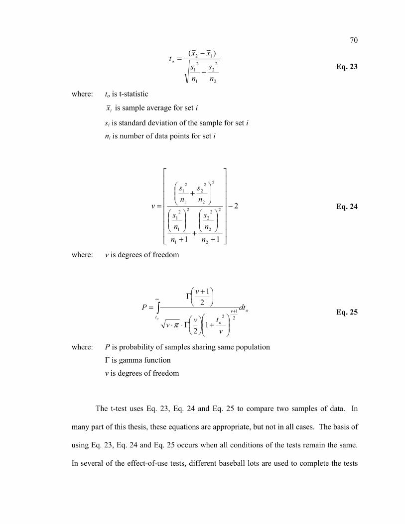
70
2
22
1
21
12 )(
ns
ns
xxto
+
−=
Eq. 23
where: to is t-statistic
ix is sample average for set i
si is standard deviation of the sample for set i ni is number of data points for set i
2
11 2
2
2
22
1
2
1
21
2
2
22
1
21
−
+
++
+
=
nns
nns
ns
ns
v Eq. 24
where: v is degrees of freedom
ot
v
o
dt
vtvv
v
Po
∫∞
+
+
Γ⋅⋅
+Γ=
21
2
12
21
π
Eq. 25
where: P is probability of samples sharing same population
Γ is gamma function
v is degrees of freedom
The t-test uses Eq. 23, Eq. 24 and Eq. 25 to compare two samples of data. In
many part of this thesis, these equations are appropriate, but not in all cases. The basis of
using Eq. 23, Eq. 24 and Eq. 25 occurs when all conditions of the tests remain the same.
In several of the effect-of-use tests, different baseball lots are used to complete the tests

71
because of physical constraints from using baseballs for a substantial quantity of testing.
Therefore, Eq. 23 and Eq. 24 had to be made appropriate for these cases. The t-statistic
and the degrees of freedom are based on combinations of uncertainty related to the
average of the data. Therefore, the addition of the uncertainty of the average of the
baseball lot baseline must be introduced into the statistical uncertainty for the comparison
of performance results. Using the underlying reasoning behind these statistical values
and for the cases where different baseball lots are used for the specific tests being
compared, Eq. 23 and Eq. 24 take the form of Eq. 26 and Eq. 27, respectively.
2
22
1
21
2
22
1
21
1122 )()(
b
b
b
b
bbo
ns
ns
ns
ns
xxxxt
+++
−−−=
Eq. 26
where: b (subscript) is respective baseball lot
4
1111 2
2
2
22
1
2
1
21
2
2
2
22
1
2
1
21
2
2
22
1
21
2
22
1
21
−
+
++
++
++
+++
=
b
b
b
b
b
b
b
b
b
b
nns
nns
nns
nns
ns
ns
ns
ns
v Eq. 27
The t-test will be used within Chapter 5 to help in determining the significance or
insignificance of the factor, either the effect of use or the effect of moisture content,
during the tests and the variability within the tests. When the t-test is used, the
probability of the two samples being from the same population, and therefore, without the
effect of an external factor, is calculated. Within most of this thesis, a 95% confidence

72
has been selected. Therefore, if the probability from the t-test analysis of the two
samples is greater than 5%, then the factor is not statistically significant. If the
probability is less then 5% then that sample does show the factor to be statistically
significant.
The paired t-test is used to compare two samples where the data are collected in
pairs. During the effect-of-moisture-content tests, each bat is tested at two moisture
contents. Therefore, a different statistic, in Eq. 28, can be used rather than the normal
unpaired t-statistic.
nSDt
Dop =
Eq. 28
where: top is paired t-statistic
D is average of differences between paired data SD is standard deviation of the differences between data
n is number of differences
4.2.3 Control Charts and Confidence Intervals
Control charts are a statistical method of presenting time-sequential test data.
Because the effect-of-use tests are performed on a bat over a long period of time, this
graphical method of inspecting the trends of the data is appropriate and valuable for
complementing the t-test results. Often used for process control, control limits are set
above and below the normal or required range of data samples. For the effect-of-use tests
performed in this thesis and keeping all other variables constrained, the “process” will
only drift if the external factor, i.e. use, changes the performance.
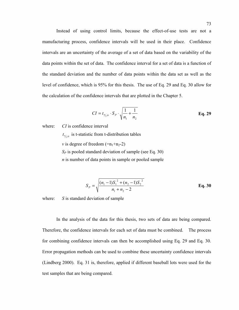
73
Instead of using control limits, because the effect-of-use tests are not a
manufacturing process, confidence intervals will be used in their place. Confidence
intervals are an uncertainty of the average of a set of data based on the variability of the
data points within the set of data. The confidence interval for a set of data is a function of
the standard deviation and the number of data points within the data set as well as the
level of confidence, which is 95% for this thesis. The use of Eq. 29 and Eq. 30 allow for
the calculation of the confidence intervals that are plotted in the Chapter 5.
21,
112 nn
StCI P +⋅⋅= υα Eq. 29
where: CI is confidence interval
υα ,2t is t-statistic from t-distribution tables
v is degree of freedom (=n1+n2-2)
SP is pooled standard deviation of sample (see Eq. 30)
n is number of data points in sample or pooled sample
2)1()1(
21
222
211
−+−+−
=nn
SnSnSP Eq. 30
where: S is standard deviation of sample
In the analysis of the data for this thesis, two sets of data are being compared.
Therefore, the confidence intervals for each set of data must be combined. The process
for combining confidence intervals can then be accomplished using Eq. 29 and Eq. 30.
Error propagation methods can be used to combine these uncertainty confidence intervals
(Lindberg 2000). Eq. 31 is, therefore, applied if different baseball lots were used for the
test samples that are being compared.
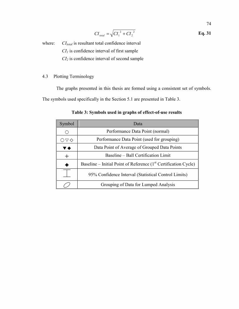
74
22
21 CICICItotal += Eq. 31
where: CItotal is resultant total confidence interval
CI1 is confidence interval of first sample
CI2 is confidence interval of second sample
4.3 Plotting Terminology
The graphs presented in this thesis are formed using a consistent set of symbols.
The symbols used specifically in the Section 5.1 are presented in Table 3.
Table 3: Symbols used in graphs of effect-of-use results
Symbol Data
Performance Data Point (normal)
Performance Data Point (used for grouping)
Data Point of Average of Grouped Data Points
Baseline – Ball Certification Limit
Baseline – Initial Point of Reference (1st Certification Cycle)
95% Confidence Interval (Statistical Control Limits)
Grouping of Data for Lumped Analysis
75
5 RESULTS / DISCUSSION
The results of the tests described in Chapter 3 are presented and discussed in this
chapter. The results of the effect-of-use tests are presented in Section 5.1, and the results
of the effect-of-moisture-content tests are presented in Section 5.2. Section 5.1 consists
of the results of the three tests completed entirely in the Baum Hitting Machine and the
two tests completed using a combination of field use and testing in the BHM, organized
chronologically. Section 5.2 consists of two subsections presenting the results of the
same-weight-method and the same-bat-method tests. Because many of the results in this
thesis show a very small change resulting from the applied factor, most of the results are
presented within the bounds of a statistical analysis. The statistical methods that will be
used throughout this chapter were explained in Section 4.2.
5.1 Results of Effect-of-Use tests
Effect-of-Use tests were performed on five different aluminum baseball bats.
Two different procedures were used for testing the bats. PD01, PD02 and PD03 were
tested entirely in the Baum Hitting Machine using the procedures explained in Section
3.2.2. PD04 and PD05 were exposed to field use and periodically tested in the BHM.
This procedure is described in Section 3.2.3. The majority of the testing time for the
effect-of-use tests was spent on PD01, PD03 and PD04. Therefore, the majority of this
section will be devoted to the results of those three samples. The other two bats will be
used to corroborate the results of PD01, PD03 and PD04.
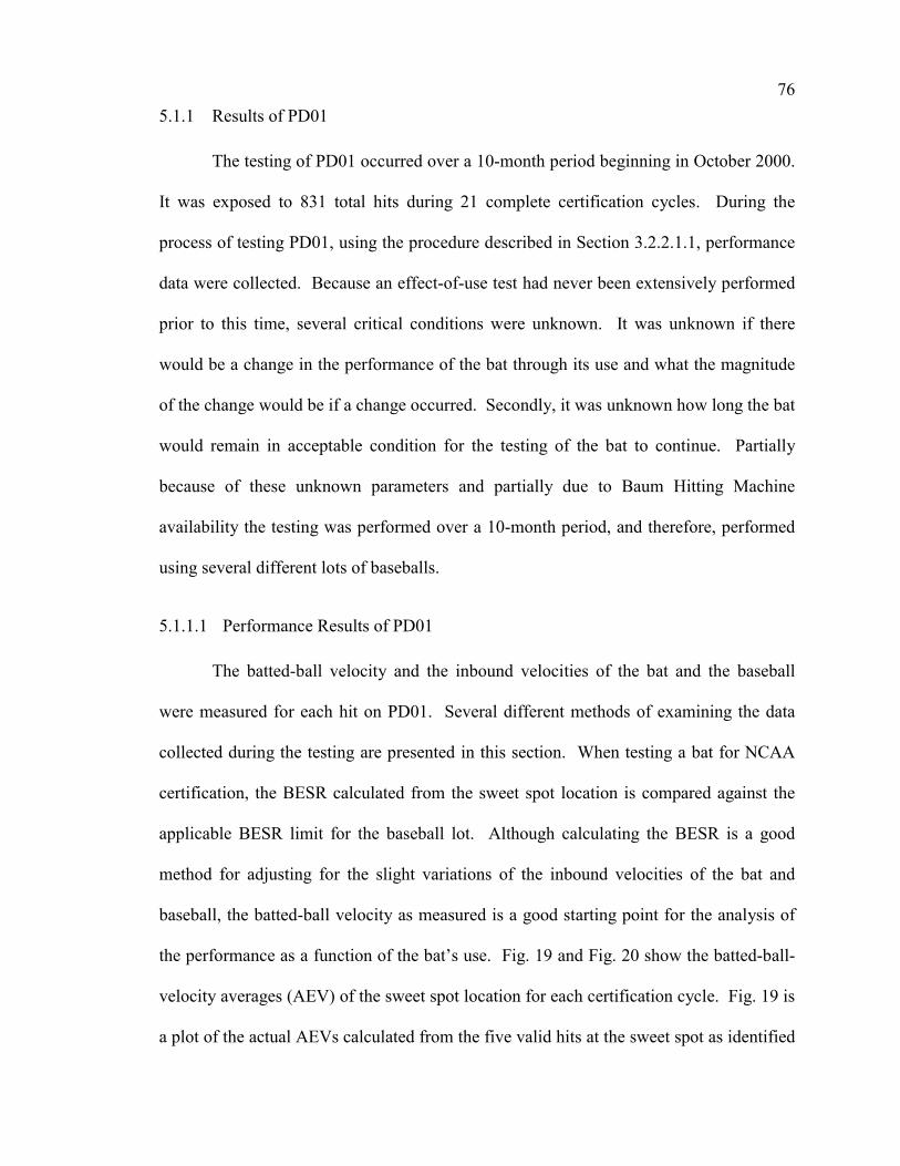
76
5.1.1 Results of PD01
The testing of PD01 occurred over a 10-month period beginning in October 2000.
It was exposed to 831 total hits during 21 complete certification cycles. During the
process of testing PD01, using the procedure described in Section 3.2.2.1.1, performance
data were collected. Because an effect-of-use test had never been extensively performed
prior to this time, several critical conditions were unknown. It was unknown if there
would be a change in the performance of the bat through its use and what the magnitude
of the change would be if a change occurred. Secondly, it was unknown how long the bat
would remain in acceptable condition for the testing of the bat to continue. Partially
because of these unknown parameters and partially due to Baum Hitting Machine
availability the testing was performed over a 10-month period, and therefore, performed
using several different lots of baseballs.
5.1.1.1 Performance Results of PD01
The batted-ball velocity and the inbound velocities of the bat and the baseball
were measured for each hit on PD01. Several different methods of examining the data
collected during the testing are presented in this section. When testing a bat for NCAA
certification, the BESR calculated from the sweet spot location is compared against the
applicable BESR limit for the baseball lot. Although calculating the BESR is a good
method for adjusting for the slight variations of the inbound velocities of the bat and
baseball, the batted-ball velocity as measured is a good starting point for the analysis of
the performance as a function of the bat’s use. Fig. 19 and Fig. 20 show the batted-ball-
velocity averages (AEV) of the sweet spot location for each certification cycle. Fig. 19 is
a plot of the actual AEVs calculated from the five valid hits at the sweet spot as identified

77
for each certification cycle. Additionally, this graph identifies the BESR limit to use as a
baseline for comparing the batted-ball performance from one cycle to another. Fig. 20 is
the resulting graph when the data are shifted such that the BESR limits are lined up to
form a single baseline. Therefore, a direct relative comparison among all the averages
regardless of which baseball lot was used during the testing can be observed.
The graphs in this section present performance versus number of hits and use a
consistent format to help with the understanding and comparison between graphs. The x-
axis on all of the graphs identifies the total number of hits, including both the valid and
invalid, to which PD01 had been exposed at the end of the certification cycle with which
the performance data are associated. All of the graphs are plotted with a y-axis on the
left-hand side identifying the batted-ball velocity or adjusted velocity, in miles-per-hour,
for the specific type of analysis that is identified with the graph. The y-axis-scale ranges
vary from graph to graph, but in as many cases as possible remain similar for
comparative purposes. In some cases, there is an addition of a y-axis on the right-hand
side of the BESR value corresponding directly to the batted-ball velocity on the left-hand
side. The data points can be identified in relation to either axis directly. The symbols
used to create the plot are identified in Table 3. For clarity and consistency, these
symbols are used as needed in the graphs.

78
0 200 400 600 800 1000Number of Hits on Bat
94
95
96
97
98
99
Bat
ted-
Bal
l Vel
ocity
(mph
)
Batted-ball Velocity (Raw Data)Ball Certification (Baseline)
Fig. 19: AEV of the sweet spot for each certification cycle with baseline for PD01
0 200 400 600 800 1000Number of Hits on Bat
94
95
96
97
98
99
Bat
ted-
Bal
l Vel
ocity
(mph
) Batted-ball VelocityBall Certification (Baseline)
Fig. 20: AEV of the sweet spot – adjusted for baseline for PD01

79
Although the raw batted-ball velocity is a good starting point for the analysis of
the results, the BESR-based batted-ball velocity can help to account for the variations of
the inbound velocities of the bat and the baseball. Therefore, Fig. 21 represents the result
of the calculation of the BESR. As in Fig. 20, the values are adjusted to consider the
various baseball lots used and their respective certification limits. The right-hand axis
identifies the average BESR value as calculated using Eq. 6 from the five hits at the
sweet spot location from each certification cycle. The left-hand axis identifies the BESR-
based batted-ball velocity corresponding to the BESR value on the right-hand axis. Each
batted-ball velocity in Fig. 21 is back calculated using Eq. 19. These performance values
are plotted with respect to the total number of hits on PD01 at the completion of the
respective certification cycle.
0 200 400 600 800 1000Number of Hits on Bat
94
95
96
97
Bat
ted-
Bal
l Vel
ocity
(mph
)
0.710
0.715
0.720
0.725
BES
R
Fig. 21: BESR based average batted-ball velocity for the sweet spot for PD01

80
Fig. 19, Fig. 20 and Fig. 21, representing the analysis of the sweet spot location
during each certification cycle, show an apparent increase in performance as the bat is
exposed to more hits. Though there is an apparent increase in performance, the data are
scattered. Therefore, determining the confidence of any increase requires the use of
statistical methods. The methods for looking at these data were explained in Section 4.2.
Using these methods, the statistical confidences of the data presented in Fig. 20 and Fig.
21 are presented later in this section.
The performance of the sweet spot of the bat is most important during the
aluminum-bat certification process, because the maximum performance of the baseball
bat is of most interest. During the effect-of-use tests, all of the impacted locations may
go through the workhardening process to a similar extent. Recall from Section 4.1.5 that
the averaging of the 25 hits over the impacted region of the bat is statistically more
representative of the performance than averaging the five hits at the sweet spot location.
Therefore, the same types of presentation of data as are in Fig. 19, Fig. 20 and Fig. 21 are
presented in Fig. 22, Fig. 23 and Fig. 24, respectively, for an average of all 25 valid hits
acquired from each certification cycle.

81
0 200 400 600 800 1000Number of Hits on Bat
93
94
95
96
97
98
Bat
ted-
Bal
l Vel
ocity
(mph
)
Batted-ball Velocity (Raw Data)Ball Certification (Baseline)
Fig. 22: AEV of all 25 valid hits for each certification cycle with baseline for PD01
0 200 400 600 800 1000Number of Hits on Bat
93
94
95
96
97
98
Bat
ted-
Bal
l Vel
ocity
(mph
) Batted-ball VelocityBall Certification (Baseline)
Fig. 23: AEV of all 25 hits – adjusted for baseline for PD01
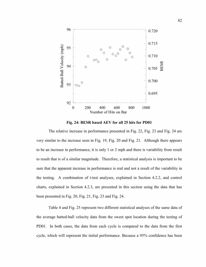
82
0 200 400 600 800 1000Number of Hits on Bat
92
93
94
95
96
Bat
ted-
Bal
l Vel
ocity
(mph
)
0.695
0.700
0.705
0.710
0.715
0.720
BES
R
Fig. 24: BESR based AEV for all 25 hits for PD01
The relative increase in performance presented in Fig. 22, Fig. 23 and Fig. 24 are
very similar to the increase seen in Fig. 19, Fig. 20 and Fig. 21. Although there appears
to be an increase in performance, it is only 1 or 2 mph and there is variability from result
to result that is of a similar magnitude. Therefore, a statistical analysis is important to be
sure that the apparent increase in performance is real and not a result of the variability in
the testing. A combination of t-test analyses, explained in Section 4.2.2, and control
charts, explained in Section 4.2.3, are presented in this section using the data that has
been presented in Fig. 20, Fig. 21, Fig. 23 and Fig. 24.
Table 4 and Fig. 25 represent two different statistical analyses of the same data of
the average batted-ball velocity data from the sweet spot location during the testing of
PD01. In both cases, the data from each cycle is compared to the data from the first
cycle, which will represent the initial performance. Because a 95% confidence has been

83
selected for the effect-of-use portion of this thesis, any probabilities less than 5.0% in the
t-test are considered to be evidence of a statistically significant change in performance.
Using this criterion, in Table 4, cycles 5, 13 and 17 are statistically not from the same
population as cycle 1. Likewise Fig. 25 shows a significant change in the same
certification cycles, identified by the error bar on each data point not including the
performance of the first cycle. The error bars are generated from a combination of the
95% confidence intervals of the first cycle, the identified cycle, and where the ball lots
were different, then additionally, the confidence intervals from the ball certifications as
well. Statistically, because there are 20 cycles being investigated and a 95% confidence is
applied, it would only be reasonable for one cycle to show a significant change.
Table 4: T-test results of probability for PD01 of AEV for the sweet spot
Cycle Probability (%) 2 95.0 3 46.0 4 67.6 5 0.7 6 73.0 7 55.4 8 13.5 9 11.4 10 29.6 11 82.2 12 10.0 13 0.4 14 44.7 15 26.3 16 47.5 17 1.2 18 87.8 19 6.2 20 44.3 21 43.7
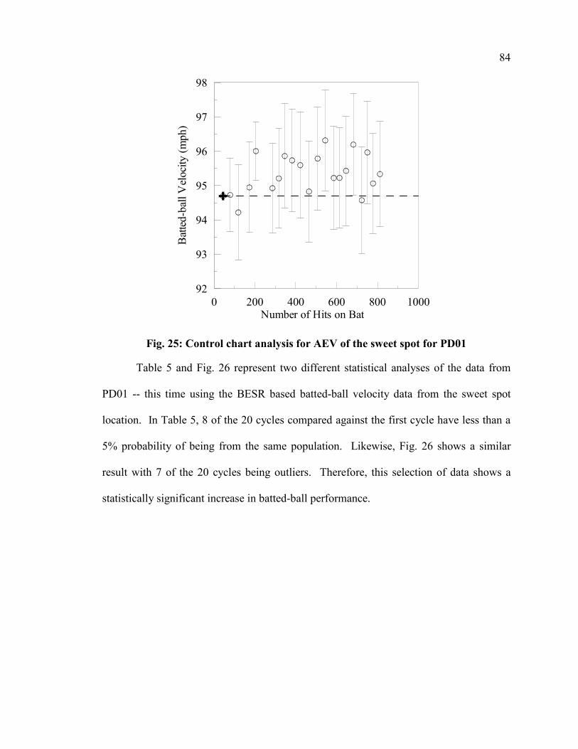
84
0 200 400 600 800 1000Number of Hits on Bat
92
93
94
95
96
97
98
Bat
ted-
ball
Vel
ocity
(mph
)
Fig. 25: Control chart analysis for AEV of the sweet spot for PD01
Table 5 and Fig. 26 represent two different statistical analyses of the data from
PD01 -- this time using the BESR based batted-ball velocity data from the sweet spot
location. In Table 5, 8 of the 20 cycles compared against the first cycle have less than a
5% probability of being from the same population. Likewise, Fig. 26 shows a similar
result with 7 of the 20 cycles being outliers. Therefore, this selection of data shows a
statistically significant increase in batted-ball performance.
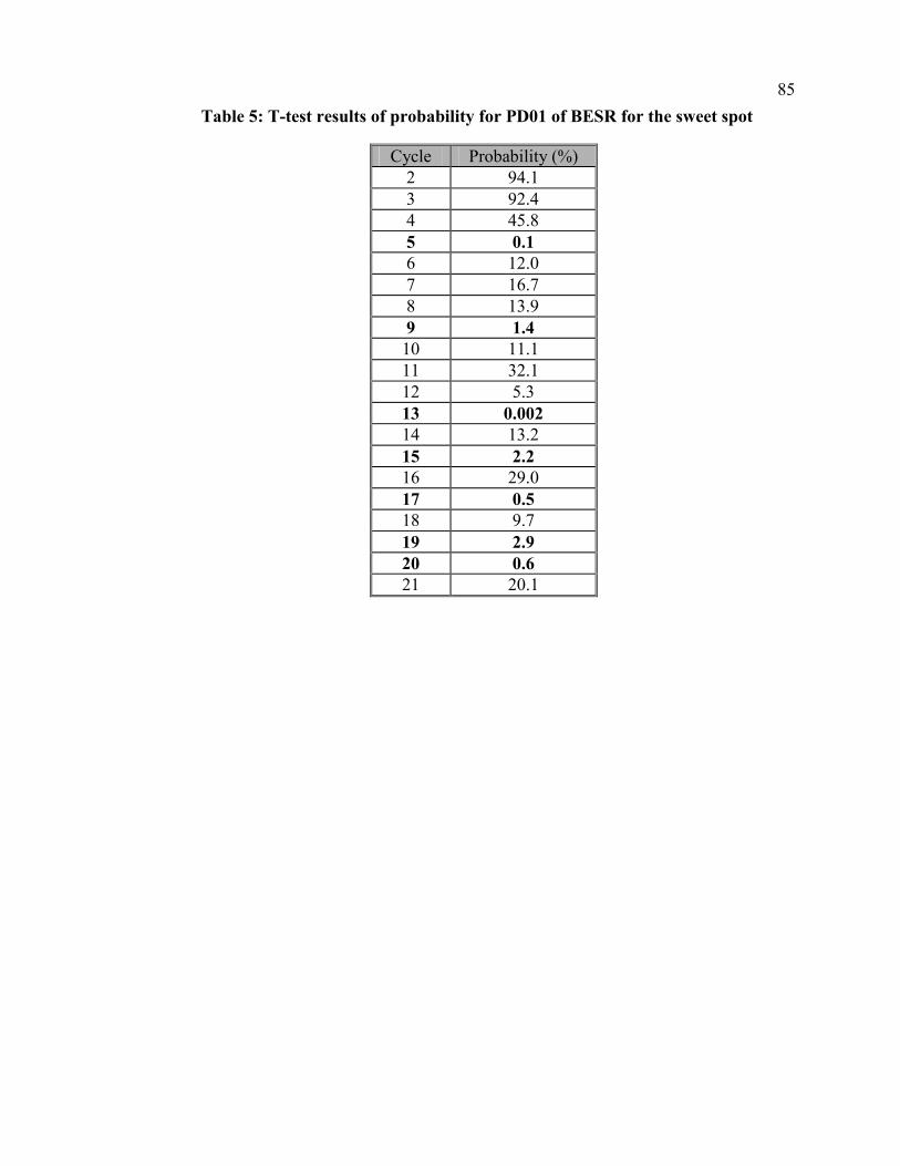
85
Table 5: T-test results of probability for PD01 of BESR for the sweet spot
Cycle Probability (%) 2 94.1 3 92.4 4 45.8 5 0.1 6 12.0 7 16.7 8 13.9 9 1.4 10 11.1 11 32.1 12 5.3 13 0.002 14 13.2 15 2.2 16 29.0 17 0.5 18 9.7 19 2.9 20 0.6 21 20.1

86
0 200 400 600 800 1000Number of Hits on Bat
92
93
94
95
96
97
98
99
Bat
ted-
ball
Vel
ocity
(mph
)
0.695
0.700
0.705
0.710
0.715
0.720
0.725
0.730
0.735
0.740
BES
R
Fig. 26: Control chart analysis for BESR for the sweet spot for PD01
Table 6 and Fig. 27 represent the statistical analyses of the average batted-ball
velocity data from the 25 valid hits during the testing of PD01. In Table 6, 12 of the 20
cycles compared against the first cycle have less than a 5% probability of being from the
same population. Likewise, Fig. 27 shows a similar result with 9 of the 20 cycles being
outliers. Therefore, this selection of data also shows a statistically significant increase in
batted-ball performance.

87
Table 6: T-test results of probability for PD01 of AEV for all 25 hits
Cycle Probability (%) 2 93.3 3 98.2 4 25.3 5 1.3 6 15.0 7 13.3 8 4.0 9 0.3 10 2.5 11 6.7 12 0.8 13 2.6 14 6.7 15 3.6 16 2.5 17 0.8 18 20.6 19 1.0 20 3.8 21 1.7

88
0 200 400 600 800 1000Number of Hits on Bat
92
93
94
95
96
Bat
ted-
ball
Vel
ocity
(mph
)
Fig. 27: Control chart analysis for AEV for the all 25 hits for PD01
Table 7 and Fig. 28 represent the statistical analyses of the BESR based batted-
ball velocity data from the 25 valid hits during the testing of PD01. In Table 7, 18 of the
20 cycles compared against the first cycle have less than a 5% probability of being from
the same population. Likewise, Fig. 28 shows a similar result with 17 of the 20 cycles
being outliers. Therefore, this selection of data shows a statistically significant increase
in batted-ball performance.

89
Table 7: T-test results of probability for PD01 of BESR for all 25 hits
Cycle Probability (%) 2 90.8 3 70.2 4 1.2 5 0.02 6 1.2 7 2.0 8 3.0 9 0.07 10 0.1 11 1.1 12 0.05 13 0.3 14 0.7 15 0.3 16 0.1 17 0.03 18 0.9 19 0.5 20 0.1 21 0.5
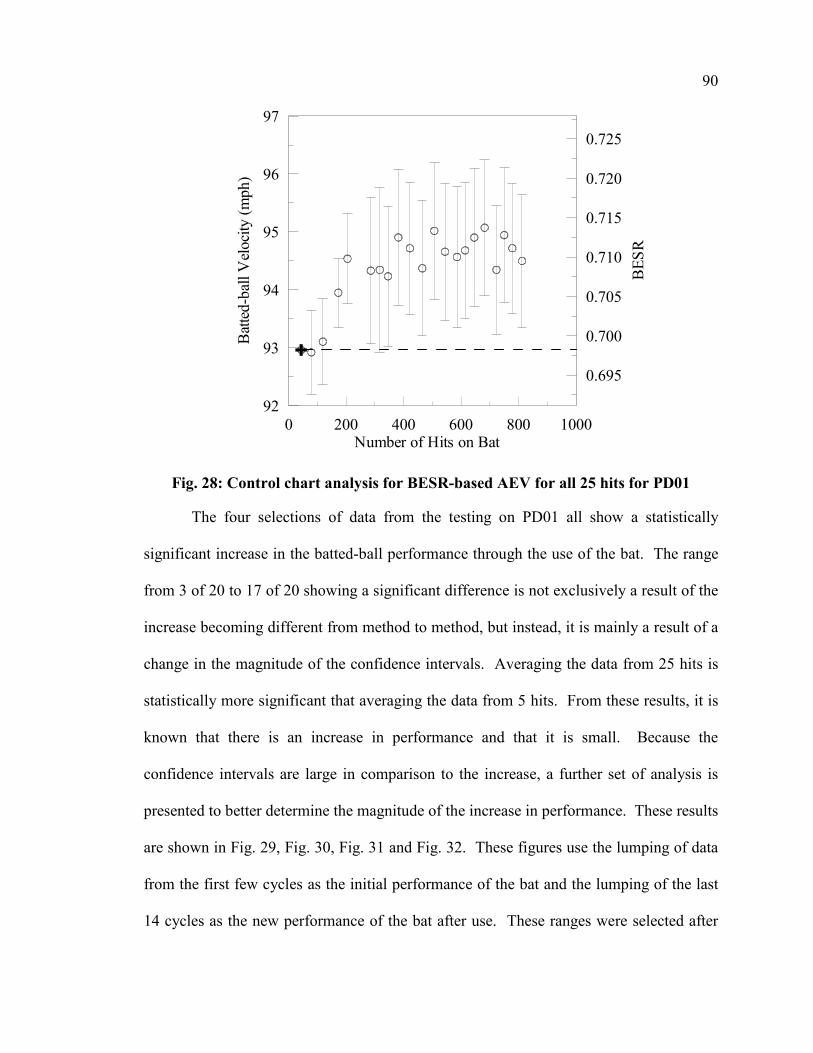
90
0 200 400 600 800 1000Number of Hits on Bat
92
93
94
95
96
97
Bat
ted-
ball
Vel
ocity
(mph
)
0.695
0.700
0.705
0.710
0.715
0.720
0.725
BES
R
Fig. 28: Control chart analysis for BESR-based AEV for all 25 hits for PD01
The four selections of data from the testing on PD01 all show a statistically
significant increase in the batted-ball performance through the use of the bat. The range
from 3 of 20 to 17 of 20 showing a significant difference is not exclusively a result of the
increase becoming different from method to method, but instead, it is mainly a result of a
change in the magnitude of the confidence intervals. Averaging the data from 25 hits is
statistically more significant that averaging the data from 5 hits. From these results, it is
known that there is an increase in performance and that it is small. Because the
confidence intervals are large in comparison to the increase, a further set of analysis is
presented to better determine the magnitude of the increase in performance. These results
are shown in Fig. 29, Fig. 30, Fig. 31 and Fig. 32. These figures use the lumping of data
from the first few cycles as the initial performance of the bat and the lumping of the last
14 cycles as the new performance of the bat after use. These ranges were selected after

91
inspecting the data to determine where the bat had not yet increased in performance and
where it appeared that the performance of the bat had leveled off. The interest in
presenting Fig. 29, Fig. 30, Fig. 31 and Fig. 32 comes from an attempt to eliminate as
much as possible the variability from test to test and hit to hit that generates the
significant scatter.

92
0 200 400 600 800 1000Number of Hits on Bat
93
94
95
96
97
Bat
ted-
ball
Vel
ocity
(mph
)
Fig. 29: Analysis of lumped AEV of the sweet spot for PD01
0 200 400 600 800 1000Number of Hits on Bat
93
94
95
96
97
Bat
ted-
ball
Vel
ocity
(mph
)
0.700
0.705
0.710
0.715
0.720
0.725
BES
R
Fig. 30: Analysis of lumped BESR-based AEV of the sweet spot for PD01

93
0 200 400 600 800 1000Number of Hits on Bat
92
93
94
95
96
Bat
ted-
ball
Vel
ocity
(mph
)
Fig. 31: Analysis of lumped AEV for all 25 hits for PD01
0 200 400 600 800 1000Number of Hits on Bat
92
93
94
95
96
Bat
ted-
ball
Vel
ocity
(mph
)
0.695
0.700
0.705
0.710
0.715
0.720
BES
R
Fig. 32: Analysis of lumped BESR-based AEV for all 25 hits for PD01

94
Table 8: Summary of lumped analysis to determine magnitude for PD01
Analysis Method Range (mph)
Min (mph)
Max (mph)
Sweet Spot AEV 0.86±0.88 -0.02 1.74 Sweet Spot BESR-based AEV 1.63±0.97 0.66 2.60
All Hits of Cycle AEV 1.20±0.95 0.25 2.15 All Hits of Cycle BESR-based AEV 1.69±0.98 0.71 2.67
Using the lumped analysis performed in Fig. 29, Fig. 30, Fig. 31 and Fig. 32 and
assuming that all of these tests are accurate to the limits of the statistical uncertainty and
that they should all reflect the same trend and magnitude, it can be concluded that the
actual increase in batted-ball performance of PD01 should fall within the intersection of
all of the ranges presented in Table 8. Therefore, the maximum of the minimums and the
minimum of the maximums becomes the likely range of performance increase. Using
this basis of analysis, the increase in performance of PD01 is in the range of 0.7 to 1.7
mph. The average of the four methods of data analysis shows a 1.3 mph increase in
batted-ball performance calculated for the mean values in the range column of Table 8.
5.1.2 Results of PD02
PD02 was the second bat to be tested for the monitoring of the effect of use on
performance. PD02 is a different model of aluminum bat than PD01. The procedure for
performing the tests is described in Section 3.2.2.2. Along with performance
measurements, presented in Section 5.1.2.1, the surface deformation and the hardness
measurements are presented in Sections 5.1.2.2 and 5.1.2.3, respectively. A total of only
147 hits within three certification cycles were recorded on PD02, because testing could
not continue after the severe denting that occurred during the testing.

95
5.1.2.1 Performance Results for PD02
Because PD02 only had three certification cycles completed, the performance
analysis is of little significance. A single plot is presented in Fig. 33 to show the general
trend of the limited results. It was chosen to present control chart analysis for the BESR-
based AEV for all 25 hits for PD02, because within the results of PD01, this was the
method that had the tightest confidence intervals. The axes have also remained the same
for comparative purposes. Fig. 33 shows a probable, but insignificant decrease in the
performance of PD02 over the three certification cycles of testing. This decrease may be
attributed to the change in the geometry of the bat’s surface during testing. The
deformations of the bat’s surface are presented in Section 5.1.2.2.
0 200 400 600 800 1000Number of Hits on Bat
92
93
94
95
96
97
Bat
ted-
Bal
l Vel
ocity
(mph
)
0.695
0.700
0.705
0.710
0.715
0.720
0.725
BES
R
Fig. 33: Control Chart Analysis for BESR-based AEV for all 25 hits for PD02
With PD02, only three certification cycles were completed. Therefore, giving too
much weight to the results would be inappropriate, but it can help to quantify the results.
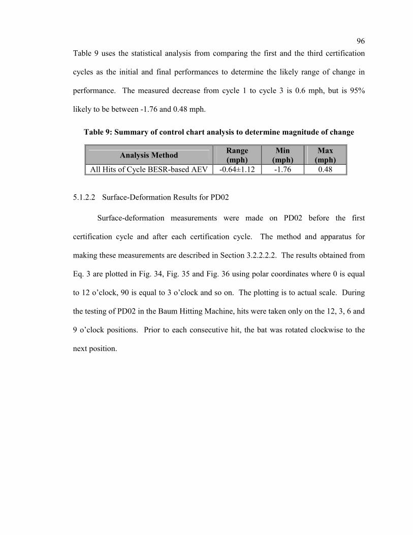
96
Table 9 uses the statistical analysis from comparing the first and the third certification
cycles as the initial and final performances to determine the likely range of change in
performance. The measured decrease from cycle 1 to cycle 3 is 0.6 mph, but is 95%
likely to be between -1.76 and 0.48 mph.
Table 9: Summary of control chart analysis to determine magnitude of change
Analysis Method Range (mph)
Min (mph)
Max (mph)
All Hits of Cycle BESR-based AEV -0.64±1.12 -1.76 0.48
5.1.2.2 Surface-Deformation Results for PD02
Surface-deformation measurements were made on PD02 before the first
certification cycle and after each certification cycle. The method and apparatus for
making these measurements are described in Section 3.2.2.2.2. The results obtained from
Eq. 3 are plotted in Fig. 34, Fig. 35 and Fig. 36 using polar coordinates where 0 is equal
to 12 o’clock, 90 is equal to 3 o’clock and so on. The plotting is to actual scale. During
the testing of PD02 in the Baum Hitting Machine, hits were taken only on the 12, 3, 6 and
9 o’clock positions. Prior to each consecutive hit, the bat was rotated clockwise to the
next position.

97
0
45
90
135
180
225
270
315
0 0.4 0.8 1.2Radius (in.)
LegendBefore 1st CycleAfter 1st CycleAfter 2nd CycleAfter 3rd Cycle
Fig. 34: Surface-deformation plot for 5.0-inch band for PD02
0
45
90
135
180
225
270
315
0 0.4 0.8 1.2Radius (in.)
LegendBefore 1st CycleAfter 1st CycleAfter 2nd CycleAfter 3rd Cycle
Fig. 35: Surface-deformation plot for 6.0-inch band for PD02
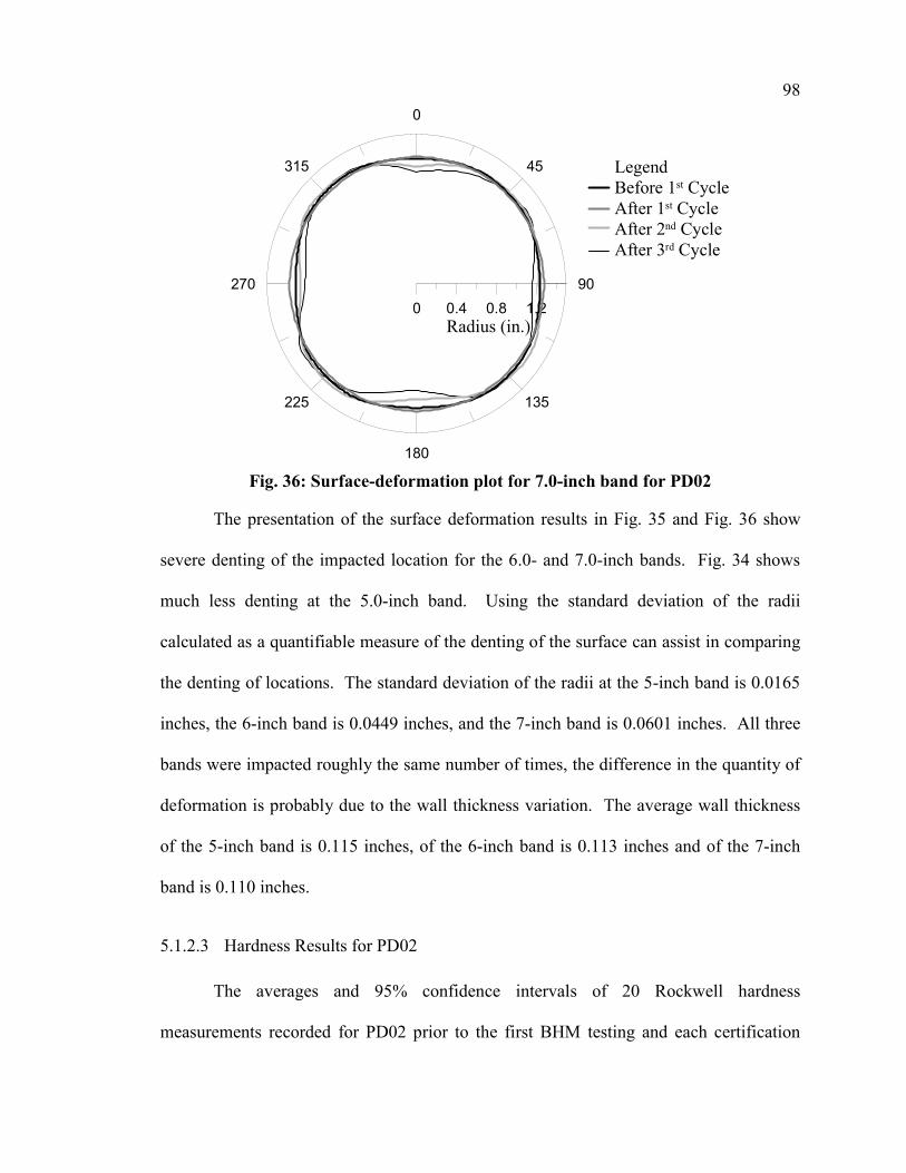
98
0
45
90
135
180
225
270
315
0 0.4 0.8 1.2Radius (in.)
LegendBefore 1st CycleAfter 1st CycleAfter 2nd CycleAfter 3rd Cycle
Fig. 36: Surface-deformation plot for 7.0-inch band for PD02
The presentation of the surface deformation results in Fig. 35 and Fig. 36 show
severe denting of the impacted location for the 6.0- and 7.0-inch bands. Fig. 34 shows
much less denting at the 5.0-inch band. Using the standard deviation of the radii
calculated as a quantifiable measure of the denting of the surface can assist in comparing
the denting of locations. The standard deviation of the radii at the 5-inch band is 0.0165
inches, the 6-inch band is 0.0449 inches, and the 7-inch band is 0.0601 inches. All three
bands were impacted roughly the same number of times, the difference in the quantity of
deformation is probably due to the wall thickness variation. The average wall thickness
of the 5-inch band is 0.115 inches, of the 6-inch band is 0.113 inches and of the 7-inch
band is 0.110 inches.
5.1.2.3 Hardness Results for PD02
The averages and 95% confidence intervals of 20 Rockwell hardness
measurements recorded for PD02 prior to the first BHM testing and each certification

99
cycle are presented in Fig. 37. The averages consist of data collected from one
measurement at the four impacted locations at each of the 5 bands. The measurements
were performed in accordance with the procedure described in Section 3.2.2.2.3. The
variability among measurements, though, gives little credibility to any trends within this
data.
0 40 80 120 160Number of Hits on Bat
75
80
85
90
95
Roc
kwel
l Har
dnes
s N
umbe
r (B
-Sca
le)
Fig. 37: Rockwell hardness measurements for PD02
5.1.3 Results of PD03
More data were collected during the testing of PD03 than for any of the other
effect-of-use bats. Unlike the testing of PD01 being extended over a 10-month period,
PD03 was tested to completion in a 3-week period during January and February 2002,
avoiding the variability from one baseball lot to another. The performance data gathered
from the 806 total hits during 26 certification cycles are presented in Section 5.1.3.1.

100
Surface-deformation data were collected prior to the first certification cycle and after
each consecutive certification cycle. The plots made from the surface-deformation
measurements are presented in Section 5.1.3.2. Periodically, Rockwell hardness
measurements were taken after certification cycles. A brief summary of the hardness is
given in Section 5.1.3.3. In addition to these other measurements, some microscopy
analyses were performed on samples cut from PD03 after the completion of the entire
test. These results are presented in Section 5.1.3.4.
5.1.3.1 Performance Results for PD03
The same methods of analyzing and presenting of the data have been employed
for PD03 as were used for PD01 in Section 5.1.1.1. Because the testing of PD03 was
completed entirely with one lot of baseballs and the lot was made large enough that the
BESR limit would not change over the course of the testing, all of the certification cycles
have the same baseline. Therefore, the confidence associated with the baseball lot does
not contribute to the uncertainty of the relative comparison between certification cycles.
For consistency purposes, the graphs in this section for PD03 will use a very
similar format to those used for PD01. The axes used in the presentation of the data are
also consistent with those used for presenting the data from PD01 in Section 5.1.1.1.
Table 3 describes the use of symbols in the plots.
The most straightforward method for presenting the data from the performance
tests is to plot the average batted-ball velocities that are calculated from the raw data
collected during the tests. Fig. 38 and Fig. 40 display the results of this calculation of the
certification cycle averages for the sweet spot location and all 25 hits, respectively. The
presentations of the BESR-based batted-ball velocity averages, which help to take the
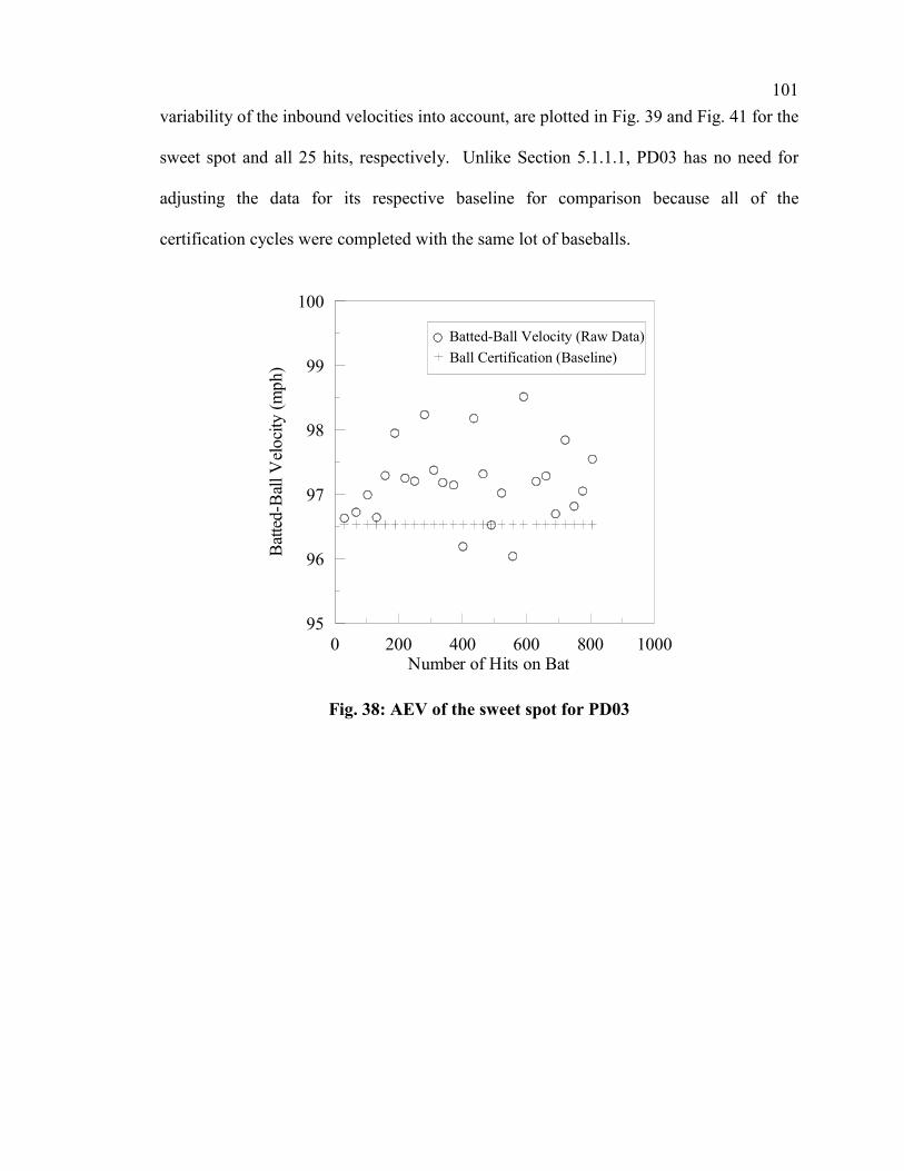
101
variability of the inbound velocities into account, are plotted in Fig. 39 and Fig. 41 for the
sweet spot and all 25 hits, respectively. Unlike Section 5.1.1.1, PD03 has no need for
adjusting the data for its respective baseline for comparison because all of the
certification cycles were completed with the same lot of baseballs.
0 200 400 600 800 1000Number of Hits on Bat
95
96
97
98
99
100B
atte
d-B
all V
eloc
ity (m
ph)
Batted-Ball Velocity (Raw Data)Ball Certification (Baseline)
Fig. 38: AEV of the sweet spot for PD03
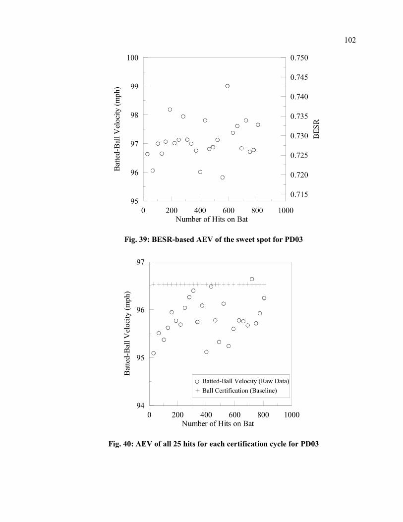
102
0 200 400 600 800 1000Number of Hits on Bat
95
96
97
98
99
100
Bat
ted-
Bal
l Vel
ocity
(mph
)
0.715
0.720
0.725
0.730
0.735
0.740
0.745
0.750
BES
R
Fig. 39: BESR-based AEV of the sweet spot for PD03
0 200 400 600 800 1000Number of Hits on Bat
94
95
96
97
Bat
ted-
Bal
l Vel
ocity
(mph
)
Batted-Ball Velocity (Raw Data)Ball Certification (Baseline)
Fig. 40: AEV of all 25 hits for each certification cycle for PD03

103
0 200 400 600 800 1000Number of Hits on Bat
94
95
96
97
Bat
ted-
Bal
l Vel
ocity
(mph
)
0.710
0.715
0.720
0.725
BES
R
Fig. 41: BESR-based AEV for all 25 hits for PD03
The batted-ball velocities in the presentation of the data from the sweet spot,
shown in Fig. 38 and Fig. 39, do not show a trend in the performance as a result from use,
because the data are very scattered. Using the average of all 25 hits from each
certification cycle, Fig. 40 and Fig. 41 hint at an increasing trend to the performance as a
function of the bat’s use, but again the data have a large scatter. Therefore, several
methods of statistical analysis will be used to interpret the results. The same methods, as
described in Section 4.2, will be employed as were used for analyzing the results from
PD01. The first method will use a t-test and be presented in a table. The t-test will be
used to compare the performance of the first certification cycle to each of the other cycles
individually and to give a probability of the two cycles being from the same population.
Within this thesis it was selected to use a 95% confidence, therefore the factor of use of
the bat can be identified as a contributing factor if more than 5% of the t-test results are
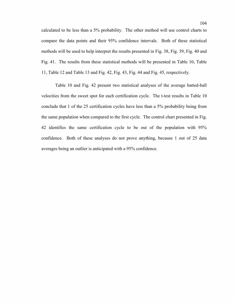
104
calculated to be less than a 5% probability. The other method will use control charts to
compare the data points and their 95% confidence intervals. Both of these statistical
methods will be used to help interpret the results presented in Fig. 38, Fig. 39, Fig. 40 and
Fig. 41. The results from these statistical methods will be presented in Table 10, Table
11, Table 12 and Table 13 and Fig. 42, Fig. 43, Fig. 44 and Fig. 45, respectively.
Table 10 and Fig. 42 present two statistical analyses of the average batted-ball
velocities from the sweet spot for each certification cycle. The t-test results in Table 10
conclude that 1 of the 25 certification cycles have less than a 5% probability being from
the same population when compared to the first cycle. The control chart presented in Fig.
42 identifies the same certification cycle to be out of the population with 95%
confidence. Both of these analyses do not prove anything, because 1 out of 25 data
averages being an outlier is anticipated with a 95% confidence.

105
Table 10: t-test results of probability for PD03 of AEV for the sweet spot
Cycle Probability (%) 2 86.7 3 73.3 4 99.0 5 25.2 6 3.8 7 26.8 8 52.6 9 14.7 10 25.8 11 56.9 12 32.9 13 61.3 14 14.5 15 19.7 16 93.9 17 66.4 18 43.1 19 7.3 20 49.0 21 34.4 22 90.4 23 18.3 24 74.0 25 41.9 26 14.3
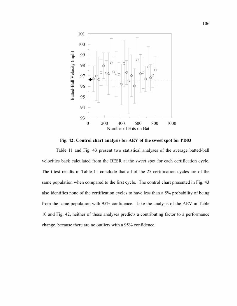
106
0 200 400 600 800 1000Number of Hits on Bat
93
94
95
96
97
98
99
100
101
Bat
ted-
Bal
l Vel
ocity
(mph
)
Fig. 42: Control chart analysis for AEV of the sweet spot for PD03
Table 11 and Fig. 43 present two statistical analyses of the average batted-ball
velocities back calculated from the BESR at the sweet spot for each certification cycle.
The t-test results in Table 11 conclude that all of the 25 certification cycles are of the
same population when compared to the first cycle. The control chart presented in Fig. 43
also identifies none of the certification cycles to have less than a 5% probability of being
from the same population with 95% confidence. Like the analysis of the AEV in Table
10 and Fig. 42, neither of these analyses predicts a contributing factor to a performance
change, because there are no outliers with a 95% confidence.

107
Table 11: t-test results of probability for PD03 of BESR-based AEV for the sweet spot
Cycle Probability (%) 2 51.8 3 78.3 4 98.4 5 56.6 6 13.3 7 63.7 8 66.5 9 29.4 10 61.0 11 76.6 12 88.5 13 61.1 14 33.5 15 84.2 16 87.5 17 64.8 18 43.2 19 7.8 20 40.1 21 33.9 22 82.0 23 34.5 24 92.4 25 85.7 26 37.3

108
0 200 400 600 800 1000Number of Hits on Bat
93
94
95
96
97
98
99
100
101
102
Bat
ted-
Bal
l Vel
ocity
(mph
)
0.7000.7050.7100.7150.7200.7250.7300.7350.7400.7450.7500.7550.760
BES
R
Fig. 43: Control chart analysis for BESR-based AEV for the sweet spot for PD03
The magnitudes of the confidence intervals, combining the confidences of both
the first cycle and the identified cycle, shown in Fig. 42 and Fig. 43 average ±1.6 mph.
This value is large in comparison to the increases that are present in the figures.
Averaging all 25 valid hits from the certification cycle can help to decrease the
magnitudes of the confidence intervals, because the calculation of confidence intervals is
very dependent upon the number of data points being analyzed. Because the 25 data
points are from different locations on the bat, there is a little more variation due to
different performances at the different locations. Table 12, Table 13, Fig. 44 and Fig. 45
represent data that have more statistical significance because they are generated from a
greater number of samples than the analyses generated from the data at the sweet spot
locations only.
109
Table 12 and Fig. 44 present two statistical analyses of the average batted-ball
velocities for all 25 valid hits from each certification cycle. The t-test results in Table 12
conclude that 7 of the 25 certification cycles have less than a 5% probability of being
from the same population when compared to the first cycle. The control chart presented
in Fig. 44 identifies the same 7 cycles to have less than a 5% probability of being from
the same population. Unlike the previous analysis for PD03, both of these analyses do
predict a contributing factor to a performance change, because 7 of 25 cycles are not
expected to be outliers with 95% confidence, if there is no external factor. Therefore, this
set of data predicts an effect to the performance of PD03 resulting from its use.

110
Table 12: t-test results of probability for PD03 of AEV for all 25 hits
Cycle Probability (%) 2 36.9 3 61.2 4 29.0 5 10.6 6 17.5 7 22.9 8 7.3 9 3.6 10 0.9 11 22.8 12 4.6 13 94.8 14 1.8 15 14.8 16 65.7 17 4.2 18 74.3 19 36.3 20 20.8 21 17.4 22 21.3 23 0.9 24 15.7 25 6.2 26 1.9

111
0 200 400 600 800 1000Number of Hits on Bat
94
95
96
97
98
Bat
ted-
Bal
l Vel
ocity
(mph
)
Fig. 44: Control chart analysis for AEV for all 25 hits for PD03
Table 13 and Fig. 45 present two statistical analyses of the average batted-ball
velocities back calculated from the BESR for all 25 valid hits from each certification
cycle. The t-test results in Table 13 conclude that 6 of the 25 certification cycles
compared to the first cycle have less than a 5% probability of being from the same
population. The control chart presented in Fig. 45 identifies 13 cycles to have less than a
5% probability of being from the same population. These analyses do predict a
contributing factor to a performance change, because more than 2 of 25 cycles are not
expected to be outliers with 95% confidence, if there is no external factor. Therefore, this
set of data also detects an effect to the performance of PD03 resulting from its use.

112
Table 13: t-test results of probability for PD03 of BESR-based AEV for all 25 hits
Cycle Probability (%) 2 90.0 3 33.0 4 34.3 5 8.6 6 9.1 7 16.9 8 18.5 9 4.6 10 3.0 11 36.5 12 6.6 13 85.7 14 5.3 15 24.3 16 47.8 17 2.7 18 61.3 19 33.6 20 16.5 21 6.3 22 16.0 23 1.0 24 15.5 25 4.1 26 1.4
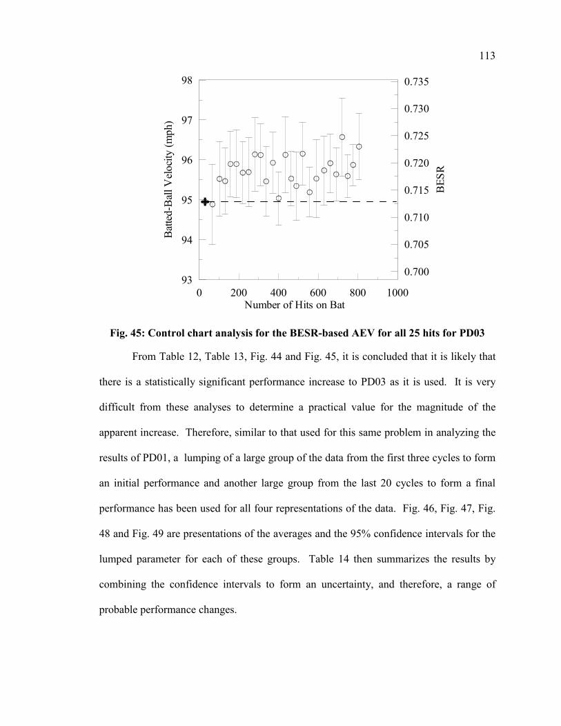
113
0 200 400 600 800 1000Number of Hits on Bat
93
94
95
96
97
98
Bat
ted-
Bal
l Vel
ocity
(mph
)
0.700
0.705
0.710
0.715
0.720
0.725
0.730
0.735
BES
R
Fig. 45: Control chart analysis for the BESR-based AEV for all 25 hits for PD03
From Table 12, Table 13, Fig. 44 and Fig. 45, it is concluded that it is likely that
there is a statistically significant performance increase to PD03 as it is used. It is very
difficult from these analyses to determine a practical value for the magnitude of the
apparent increase. Therefore, similar to that used for this same problem in analyzing the
results of PD01, a lumping of a large group of the data from the first three cycles to form
an initial performance and another large group from the last 20 cycles to form a final
performance has been used for all four representations of the data. Fig. 46, Fig. 47, Fig.
48 and Fig. 49 are presentations of the averages and the 95% confidence intervals for the
lumped parameter for each of these groups. Table 14 then summarizes the results by
combining the confidence intervals to form an uncertainty, and therefore, a range of
probable performance changes.
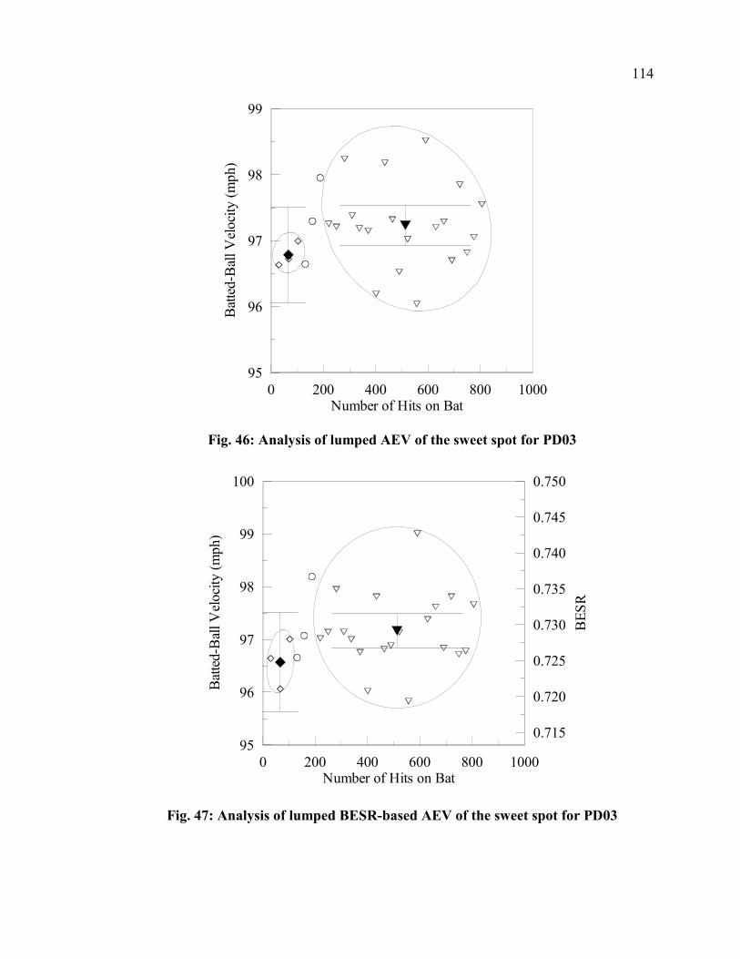
114
0 200 400 600 800 1000Number of Hits on Bat
95
96
97
98
99
Bat
ted-
Bal
l Vel
ocity
(mph
)
Fig. 46: Analysis of lumped AEV of the sweet spot for PD03
0 200 400 600 800 1000Number of Hits on Bat
95
96
97
98
99
100
Bat
ted-
Bal
l Vel
ocity
(mph
)
0.715
0.720
0.725
0.730
0.735
0.740
0.745
0.750
BES
R
Fig. 47: Analysis of lumped BESR-based AEV of the sweet spot for PD03

115
0 200 400 600 800 1000Number of Hits on Bat
94
95
96
97
Bat
ted-
Bal
l Vel
ocity
(mph
)
Fig. 48: Analysis of lumped AEV for all 25 hits for PD03
0 200 400 600 800 1000Number of Hits on Bat
94
95
96
97
Bat
ted-
Bal
l Vel
ocity
(mph
)
0.710
0.715
0.720
0.725
BES
R
Fig. 49: Analysis of lumped BESR-based AEV for all 25 hits for PD03

116
Table 14: Summary of lumped analysis to determine magnitude for PD03
Analysis Method Range (mph)
Min (mph)
Max (mph)
Sweet Spot AEV 0.45±0.81 -0.36 1.26 Sweet Spot BESR-based AEV 0.60±0.93 -0.33 1.53
All Hits of Cycle AEV 0.56±0.43 0.13 0.99 All Hits of Cycle BESR-based AEV 0.66±0.45 0.21 1.11
Using the lumped analyses shown in Fig. 46, Fig. 47, Fig. 48 and Fig. 49 and
assuming that all of these tests are accurate to the limits of the statistical uncertainty and
that they should all reflect the same trend and magnitude, it can be concluded that the
actual increase in batted-ball performance of PD03 should fall within the intersection of
all of the ranges presented in Table 14. Therefore, the maximum of the minimums and
the minimum of the maximums becomes the range. Using this basis of analysis, the
increase in performance of PD03 is in the range of 0.2 to 1.0 mph. The average of the
four methods of data analysis indicates a 0.6 mph increase in batted-ball performance
calculated from the mean values in the range column of Table 14.
5.1.3.2 Surface-Deformation Results for PD03
Surface-deformation measurements were part of the testing sequence for PD03
occurring before the first certification cycle and after each certification cycle. The
method and apparatus for making these measurements are described in Section 3.2.2.2.2.
The results obtained from Eq. 3 are plotted in Fig. 50, Fig. 51 and Fig. 52 using polar
coordinates where 0 is equal to 12 o’clock, 90 is equal to 3 o’clock and so on. The
plotting is to actual scale. As opposed to the testing of PD02, hits were taken randomly
on PD03 at all 12 clock positions prior to repeating another random sequence through the

117
12 positions. This “random” rotation led to more evenly distributed hitting and is the
primary reason for significantly less denting.
0
45
90
135
180
225
270
315
0 0.4 0.8 1.2Radius (in.)
LegendBefore Cycle 1After Cycles 1-25After Cycle 26
Fig. 50: Surface-deformation plot for 5.0-inch band for PD03
0
45
90
135
180
225
270
315
0 0.4 0.8 1.2Radius (in.)
LegendBefore Cycle 1After Cycles 1-25After Cycle 26
Fig. 51: Surface-deformation plot for 6.0-inch band for PD03

118
0
45
90
135
180
225
270
315
0 0.4 0.8 1.2Radius (in.)
LegendBefore Cycle 1After Cycles 1-25After Cycle 26
Fig. 52: Surface-deformation plot for 7.0-inch band for PD03
The presentation of the surface deformation results in Fig. 50, Fig. 51 and Fig. 52
show essentially no denting of the impacted locations. Using the standard deviation of
the radii calculated as a quantifiable measure of the denting of the surface can assist in
comparing the denting of locations. The standard deviation of the radii at the 5-inch band
is 0.0049 inches, the 6-inch band is 0.0062 inches and the 7-inch band is 0.0047 inches.
Therefore, the performance results for this bat, in Section 5.1.3.1, are not influenced by a
change in bat’s geometry as was likely the case with the performance measured for
PD02, which had an average of 0.0405 inches for the standard deviations of the radii.
5.1.3.3 Hardness Results for PD03
The averages and 95% confidence intervals of 20 Rockwell hardness
measurements recorded for PD03 prior to its first testing in the BHM and then after the
third, eighth, fifteenth and twenty-second certification cycles are presented in Fig. 53.
The measurements were performed using the method described in Section 3.2.2.3.3.

119
Though the variability between measurements is less than was measured for PD02, there
remains little credibility to any trends within this Rockwell hardness data.
0 200 400 600Number of Hits on Bat
90
91
92
93
94
95
Roc
kwel
l Har
dnes
s N
umbe
r (B
-Sca
le)
Fig. 53: Rockwell hardness measurements for PD03
A procedure for measuring the hardness of the surface of PD03 using a Vickers
hardness test was also described in Section 3.2.2.3.3. Fig. 54 presents the results of the
data collected during these hardness measurements. The average hardness based on 20
measurements is presented along with the 95% confidence interval based on the
variability among the different values. Because the tests used microhardness procedures
and the tests were performed on small, prepared and flat samples, the results were very
consistent, identified by the narrow 95% confidence intervals, within each specific
location. The three locations were chosen to represent locations with different quantities
of impacting during the performance testing. The 6-inch location, regions A and B in
Fig. 55, represents the heavily impacted region. The 2-inch location, regions E and F in

120
Fig. 55, represents the un-impacted region of the bat, essentially modeling the condition
of the bat prior to being used. The 4.5-inch location, regions C and D in Fig. 55,
represents a region of less impacting and light impacts, therefore helping to represent the
condition of a partially used bat.
6-inch 4.5-inch 2-inchPosition of Tests from Barrel End of Bat
180
185
190
195
200
205V
icke
rs H
ardn
ess N
umbe
r
Fig. 54: Vickers hardness measurements for PD03
Fig. 55: Sample locations identified in picture of barrel of PD03

121
The hardness results in Fig. 54 identify a softening of the material as the bat is
impacted. Because PD03 could not be cut and tested for hardness and then performance
tested, the results from the 2-inch location are intended to represent the material hardness
of the bat’s barrel prior to the performance testing being conducted. Similarly, the results
from the 4.5-inch location are intended to represent the material hardness of the bat’s
barrel after some performance testing. With the assumption that the entire barrel was of a
similar hardness prior to any performance testing as would be expected, it appears that
the impacted region of the bat experiences a softening as a result of being used. Section
5.1.3.1 identifies an increase in the performance of PD03 after the bats has been used.
Therefore, the theory of workhardening in Section 2.2.1 does not explain the mechanism
of this increase in performance. Therefore, a different theory will be proposed in an
attempt to explain the mechanism that allows an aluminum bat to soften and yet increase
in performance during its use.
The theory of workhardening states that hardening is an increase in the yield
strength, and therefore, allows more energy to be store in the collision. If this principle
were to dominate the performance of a bat, a softening of the impacted region would
yield a decrease in bat performance. Because there is an increase in performance other
conditions of the impact must dominate the performance at the test speeds. Because the
surface is softer, the bat may deflect more during the collision and therefore, several
conditions of the impact that have changed are the time duration of the impact and the
ratio of the deformation of the bat to that of the ball. If the time duration of impact is
extended, then more of the bat’s mass is dynamically seen by the ball and more collision
energy transferred to the baseball. The softening of the bat’s material is mechanically

122
similar to a thinning of the wall. This theory implies that the contact time during the
collision is more influential on the performance than is the yield strength of the material.
Secondly and as important is the change in the ratio of the bat deformation to the ball
deformation. The bat is considerably more efficient than the ball during the collision.
From this standpoint, if the bat’s surface becomes softer, the bat will compress more and
not require the ball to deform as much. Because the deformation of the ball is less
efficient than the bat, there is a reduction in the total energy losses during the collision
and therefore a greater bat performance. These theories imply that the contact time
during the collision and the ratio of deformation are more influential on the performance
than is the yield strength of the material.
5.1.3.4 Microscopy Results for PD03
Two methods of microcopy were performed on samples cut from PD03 after it
had been performance tested. These methods were Transition Electron Microscopy and
Atomic Force Microscopy, both described in Section 3.2.2.3.4. Neither of these methods
showed a distinct change from the impacted region to the non-impacted region, but some
results were obtained and are presented in this section. Fig. 56 identifies the average and
95% confidence interval of four grain boundary volume fractions measured using a TEM
as compared between the impacted 6-inch position and the non-impacted 2-inch position.
These volume fractions are not significantly different. Fig. 57 is one of the images
obtained from the TEM for the 2-inch location. Image processing software was used to
obtain the volume fraction from this image. The lighter areas of the image represent the
grain boundary volume. Fig. 58 is a three dimensional depiction of the information
gained from the AFM test performed on a sample from the 6-inch location. The test
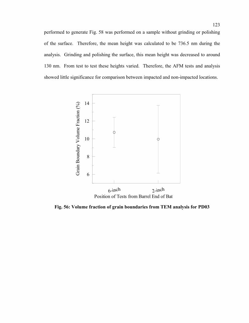
123
performed to generate Fig. 58 was performed on a sample without grinding or polishing
of the surface. Therefore, the mean height was calculated to be 736.5 nm during the
analysis. Grinding and polishing the surface, this mean height was decreased to around
130 nm. From test to test these heights varied. Therefore, the AFM tests and analysis
showed little significance for comparison between impacted and non-impacted locations.
6-inch 2-inchPosition of Tests from Barrel End of Bat
6
8
10
12
14
Gra
in B
ound
ary
Vol
ume
Frac
tion
(%)
Fig. 56: Volume fraction of grain boundaries from TEM analysis for PD03

124
Fig. 57: TEM image from 2-inch location of PD03
Fig. 58: AFM 3-D image of the surface roughness of 6-inch location of PD03

125
5.1.4 Results of PD04
The three bats tested entirely in the Baum Hitting Machine, PD01, PD02 and
PD03, are obviously exposed to use that is far more controlled than a bat used during
games and practices by baseball players. The primary focus of this portion of this thesis
is to determine the effect to the performance of an aluminum bat when it is used by
players during practices and games. Therefore, the testing of PD04 uses the method
described in Section 3.2.3.1 to try to inspect the performance trend with a combination of
testing in the BHM and field use.
PD04 was exposed to a total of 2371 hits during its testing and field use. Of this
total, 232 were full-contact hits in the BHM, 1590 were good-contact hits in the field, and
the remaining 549 were light-contact field hits. During the presentation of the results in
this section, only the 1822 full-contact or good-contact hits will be used, because the
light-contact hits should contribute minimally to the small 2-inch band that is
performance tested. The sum of the full-contact and good contact hits at the end of each
certification cycle will be plotted on the x-axis.
The performance results collected from the testing in the BHM are presented in
Section 5.1.4.1. A total of seven certification cycles were performed on PD04. Surface-
deformation measurements were taken prior to the first certification cycle and then after
each certification cycle and field-use session. The results of these measurements are
presented in Section 5.1.4.2.

126
5.1.4.1 Performance Results of PD04
Very similar methods of analyzing and presenting of the data have been employed
for PD04 as were used for PD01 and PD03 in Sections 5.1.1.1 and 5.1.3.1, respectively.
Because the testing of PD04, like PD03, was completed entirely with one lot of baseballs
and the lot was made large enough that the BESR limit would not change over the course
of the testing, all of the certification cycles have the same baseline. Therefore, the
confidence associated with the baseball lot does not contribute to the uncertainty of the
relative comparison between certification cycles.
For consistency purposes, the graphs in this section for PD04 will use a very
similar format to those used for PD01 and PD03. Table 3 describes the use of symbols in
the plots.
The most straightforward method for presenting the data from the performance
tests is to plot the average batted-ball velocities that are calculated from the raw data
collected during the tests. Fig. 59 and Fig. 61 display the results of this calculation of the
certification cycle averages for the sweet spot location and the 5.0-, 5.5-, and 6.0-inch
locations, respectively. The analysis of PD04 with the three locations differs from the
analysis of PD01 and PD03, because the testing of the 6.5-inch location was missed
during the first certification cycle. The lack of this data made the same type of analysis
as was used for PD01 and PD03 impossible, though the analysis used consisting of the
data from the 5.0-, 5.5- and 6.0-inch locations has the same benefits as the analysis of all
25 hits in that the additional data increases the confidence of the average when comparing
statistically. The presentations of the BESR-based batted-ball velocity averages, which

127
help to take the variability of the inbound velocities into account, are plotted in Fig. 60
and Fig. 62 for the sweet spot and the 5.0-, 5.5- and 6.0-inch locations.

128
0 400 800 1200 1600Number of Hits on Bat
95
96
97
98
99
Bat
ted-
Bal
l Vel
ocity
(mph
)
Batted-Ball Velocity (Raw Data)Ball Certification (Baseline)
Fig. 59: AEV of the sweet spot for PD04
0 400 800 1200 1600Number of Hits on Bat
95
96
97
98
Bat
ted-
Bal
l Vel
ocity
(mph
)
0.715
0.720
0.725
0.730
0.735
BES
R
Fig. 60: BESR-based AEV of the sweet spot for PD04

129
0 400 800 1200 1600Number of Hits on Bat
94
95
96
97
98
Bat
ted-
Bal
l Vel
ocity
(mph
)
Batted-Ball Velocity (Raw Data)Ball Certification (Baseline)
Fig. 61: AEV of 15 hits at 5.0-, 5.5- and 6.0-inch positions for PD04
0 400 800 1200 1600Number of Hits on Bat
94
95
96
97
98
Bat
ted-
Bal
l Vel
ocity
(mph
)
0.710
0.715
0.720
0.725
0.730
0.735
BES
R
Fig. 62: BESR-based AEV at 5.0-, 5.5- and 6.0-inch positions for PD04

130
The batted-ball velocities in the presentation of the data from the sweet spot,
shown in Fig. 59 and Fig. 60, and the average of the 15 hits acquired from the 5.0-, 5.5-
and 6.0-inch locations from each certification cycle, shown in Fig. 61 and Fig. 62,
identify significant scatter through the seven data points. Therefore, statistics will be
used to determine the significance of the scatter. The same methods, as are described in
Section 4.2, will be employed as were used for analyzing the results from PD01 and
PD03. The first method will use a t-test and be presented in a table. The t-test will be
used to compare the performance of the first certification cycle to each of the other cycles
individually and give a probability of the two cycles being from the same population.
Within this thesis, it was selected to use a 95% confidence; therefore the factor of use of
the bat can be identified as a contributing factor if more than 5% of the t-test results are
calculated to be less than a 5% probability. The other method will use control charts to
compare the data points and their 95% confidence intervals. Both of these statistical
methods will be used to help interpret the results presented in Fig. 59, Fig. 60, Fig. 61 and
Fig. 62. The results from these statistical methods will be presented in Table 15, Table
16, Table 17 and Table 18 and Fig. 63, Fig. 64, Fig. 65 and Fig. 66, respectively.
Table 15 and Fig. 63 present two statistical analyses of the average batted-ball
velocities from the sweet spot for each certification cycle. Both of these analyses show
no statistical significant difference in the performance of PD04 with a 95% confidence,
because there are no outliers among the data averages.
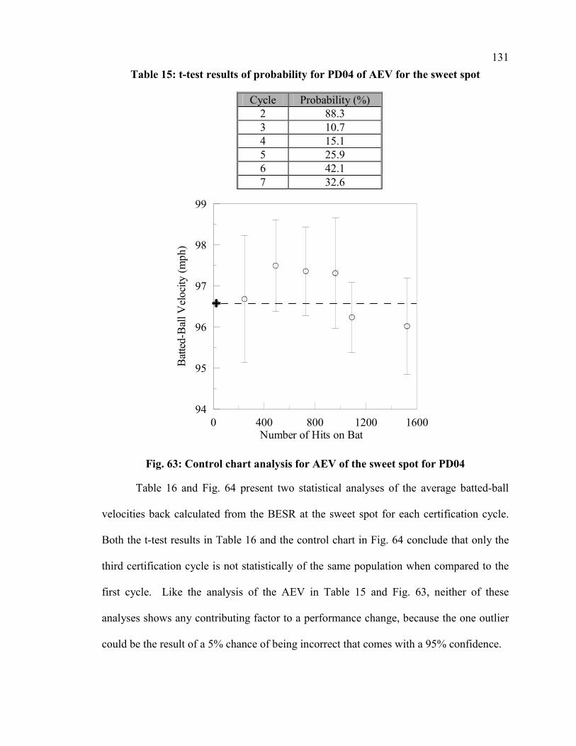
131
Table 15: t-test results of probability for PD04 of AEV for the sweet spot
Cycle Probability (%) 2 88.3 3 10.7 4 15.1 5 25.9 6 42.1 7 32.6
0 400 800 1200 1600Number of Hits on Bat
94
95
96
97
98
99
Bat
ted-
Bal
l Vel
ocity
(mph
)
Fig. 63: Control chart analysis for AEV of the sweet spot for PD04
Table 16 and Fig. 64 present two statistical analyses of the average batted-ball
velocities back calculated from the BESR at the sweet spot for each certification cycle.
Both the t-test results in Table 16 and the control chart in Fig. 64 conclude that only the
third certification cycle is not statistically of the same population when compared to the
first cycle. Like the analysis of the AEV in Table 15 and Fig. 63, neither of these
analyses shows any contributing factor to a performance change, because the one outlier
could be the result of a 5% chance of being incorrect that comes with a 95% confidence.

132
Table 16: t-test results of probability for PD04 of BESR-based AEV for the sweet spot
Cycle Probability (%) 2 71.0 3 3.8 4 51.2 5 51.2 6 20.7 7 73.9
0 400 800 1200 1600Number of Hits on Bat
94
95
96
97
98
99
Bat
ted-
Bal
l Vel
ocity
(mph
)
0.710
0.715
0.720
0.725
0.730
0.735
0.740
BES
R
Fig. 64: Control chart analysis for BESR-based AEV for the sweet spot for PD04
During the analysis of PD01 and PD03, the confidence intervals generated from
the data at the sweet spot have been larger than those generated when averaging data
from multiple locations. This same trend is anticipated with the analysis of PD04 even
though only the 5.0-, 5.5- and 6.0-inch locations on the bat are being averaged. Table 17
and Table 18 and Fig. 65 and Fig. 66 represent the statistical analyses from the data of the
5.0-, 5.5- and 6.0-inch locations.

133
Table 17 and Fig. 65 present two statistical analyses of the average batted-ball
velocities measured from the 5.0-, 5.5- and 6.0-inch locations for each certification cycle.
The t-test results in Table 17 conclude that 2 of the 6 certification cycles are statistically
not of the same population when compared to the first cycle. The control chart presented
in Fig. 44 identifies the same 2 cycles to have less than a 5% probability of being from
the same population with a 95% confidence. Unlike the previous analysis for PD04, both
of these analyses do begin to indicate a contributing factor to a performance change,
because 2 of 6 cycles are not expected to be outliers with 95% confidence, if there is no
external factor. Therefore, this set of data implies a slight effect to the performance of
PD04 resulting from its use.
Table 17: t-test results of probability for PD04 of AEV for 5.0-, 5.5- and 6.0-inch locations
Cycle Probability (%) 2 97.5 3 0.4 4 58.8 5 4.4 6 23.9 7 21.9

134
0 400 800 1200 1600Number of Hits on Bat
94
95
96
97
98
99
Bat
ted-
Bal
l Vel
ocity
(mph
)
Fig. 65: Control chart analysis of AEV for 5.0-, 5.5- and 6.0-inch locations for PD04
Table 18 and Fig. 66 present two statistical analyses of the average batted-ball
velocities back calculated from the BESR for the 5.0-, 5.5- and 6.0-inch locations of each
certification cycle. The t-test results in Table 18 conclude that 1 of the 6 certification
cycles is statistically not of the same population when compared to the first cycle. The
control chart presented in Fig. 66 identifies the same cycle to have less than a 5%
probability of being from the same population with 95% confidence. Though this one
outlier could be by chance, there is a chance that PD04’s performance does show an
increase during its use.
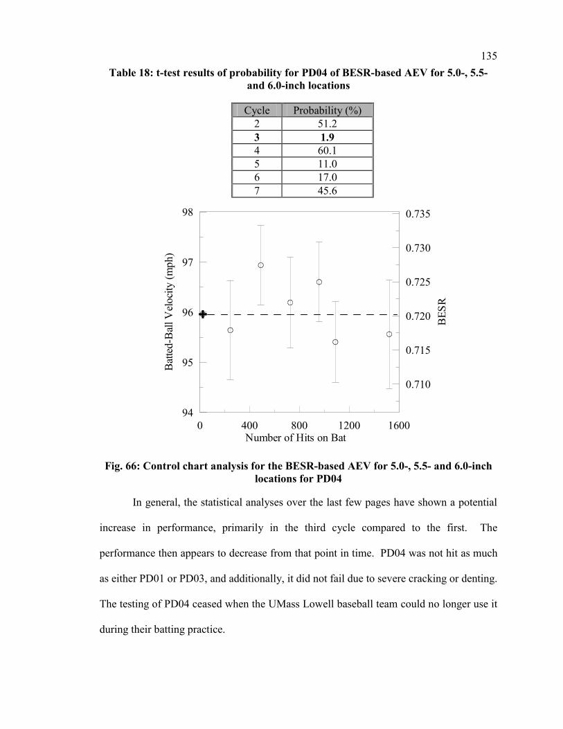
135
Table 18: t-test results of probability for PD04 of BESR-based AEV for 5.0-, 5.5- and 6.0-inch locations
Cycle Probability (%) 2 51.2 3 1.9 4 60.1 5 11.0 6 17.0 7 45.6
0 400 800 1200 1600Number of Hits on Bat
94
95
96
97
98
Bat
ted-
Bal
l Vel
ocity
(mph
)
0.710
0.715
0.720
0.725
0.730
0.735
BES
R
Fig. 66: Control chart analysis for the BESR-based AEV for 5.0-, 5.5- and 6.0-inch locations for PD04
In general, the statistical analyses over the last few pages have shown a potential
increase in performance, primarily in the third cycle compared to the first. The
performance then appears to decrease from that point in time. PD04 was not hit as much
as either PD01 or PD03, and additionally, it did not fail due to severe cracking or denting.
The testing of PD04 ceased when the UMass Lowell baseball team could no longer use it
during their batting practice.

136
Though the statistical analyses do not show any statistically significant increases
as PD01 and PD03 did, PD04 does hint at a slight increase. Therefore, similar to that
used for PD01 and PD03, a lumping of a large group of the data from the first two cycles
to form an initial performance and another large group from the last five cycles to form a
final performance has been used for all four representations of the data. Fig. 67, Fig. 68,
Fig. 69 and Fig. 70 present the averages and the 95% confidence intervals for the lumped
parameter for each of these groups. Table 19 then summarizes the results by combining
the confidence intervals to form an uncertainty, and therefore, a range of probable
performance changes.
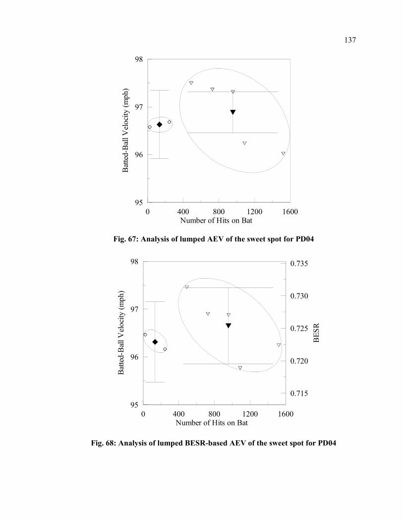
137
0 400 800 1200 1600Number of Hits on Bat
95
96
97
98
Bat
ted-
Bal
l Vel
ocity
(mph
)
Fig. 67: Analysis of lumped AEV of the sweet spot for PD04
0 400 800 1200 1600Number of Hits on Bat
95
96
97
98
Bat
ted-
Bal
l Vel
ocity
(mph
)
0.715
0.720
0.725
0.730
0.735
BES
R
Fig. 68: Analysis of lumped BESR-based AEV of the sweet spot for PD04

138
0 400 800 1200 1600Number of Hits on Bat
94
95
96
97
98
Bat
ted-
Bal
l Vel
ocity
(mph
)
Fig. 69: Analysis of lumped AEV for 5.0-, 5.5- and 6.0-inch locations for PD04
0 400 800 1200 1600Number of Hits on Bat
94
95
96
97
98
Bat
ted-
Bal
l Vel
ocity
(mph
)
0.710
0.715
0.720
0.725
0.730
0.735
BES
R
Fig. 70: Analysis of lumped BESR-based AEV for 5.0-, 5.5- and 6.0-inch locations
for PD04
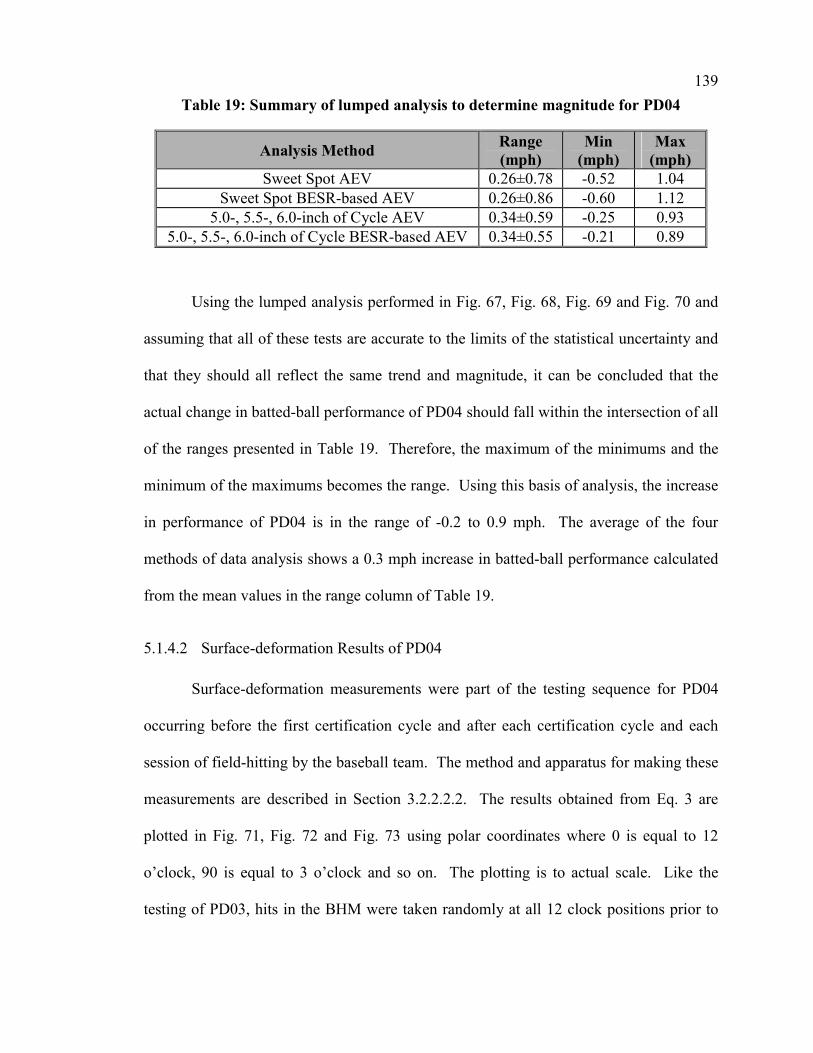
139
Table 19: Summary of lumped analysis to determine magnitude for PD04
Analysis Method Range (mph)
Min (mph)
Max (mph)
Sweet Spot AEV 0.26±0.78 -0.52 1.04 Sweet Spot BESR-based AEV 0.26±0.86 -0.60 1.12
5.0-, 5.5-, 6.0-inch of Cycle AEV 0.34±0.59 -0.25 0.93 5.0-, 5.5-, 6.0-inch of Cycle BESR-based AEV 0.34±0.55 -0.21 0.89
Using the lumped analysis performed in Fig. 67, Fig. 68, Fig. 69 and Fig. 70 and
assuming that all of these tests are accurate to the limits of the statistical uncertainty and
that they should all reflect the same trend and magnitude, it can be concluded that the
actual change in batted-ball performance of PD04 should fall within the intersection of all
of the ranges presented in Table 19. Therefore, the maximum of the minimums and the
minimum of the maximums becomes the range. Using this basis of analysis, the increase
in performance of PD04 is in the range of -0.2 to 0.9 mph. The average of the four
methods of data analysis shows a 0.3 mph increase in batted-ball performance calculated
from the mean values in the range column of Table 19.
5.1.4.2 Surface-deformation Results of PD04
Surface-deformation measurements were part of the testing sequence for PD04
occurring before the first certification cycle and after each certification cycle and each
session of field-hitting by the baseball team. The method and apparatus for making these
measurements are described in Section 3.2.2.2.2. The results obtained from Eq. 3 are
plotted in Fig. 71, Fig. 72 and Fig. 73 using polar coordinates where 0 is equal to 12
o’clock, 90 is equal to 3 o’clock and so on. The plotting is to actual scale. Like the
testing of PD03, hits in the BHM were taken randomly at all 12 clock positions prior to

140
repeating another random sequence through the 12 positions, but the field hits were
randomly spread over much of the barrel of the bat.
0
45
90
135
180
225
270
315
0 0.4 0.8 1.2Radius (in.)
LegendBefore 1st TestBetween TestsAfter Last Test
Fig. 71: Surface-deformation plot for 5.0-inch band for PD04
0
45
90
135
180
225
270
315
0 0.4 0.8 1.2Radius (in.)
LegendBefore 1st TestBetween TestsAfter Last Test
Fig. 72: Surface-deformation plot for 6.0-inch band for PD04
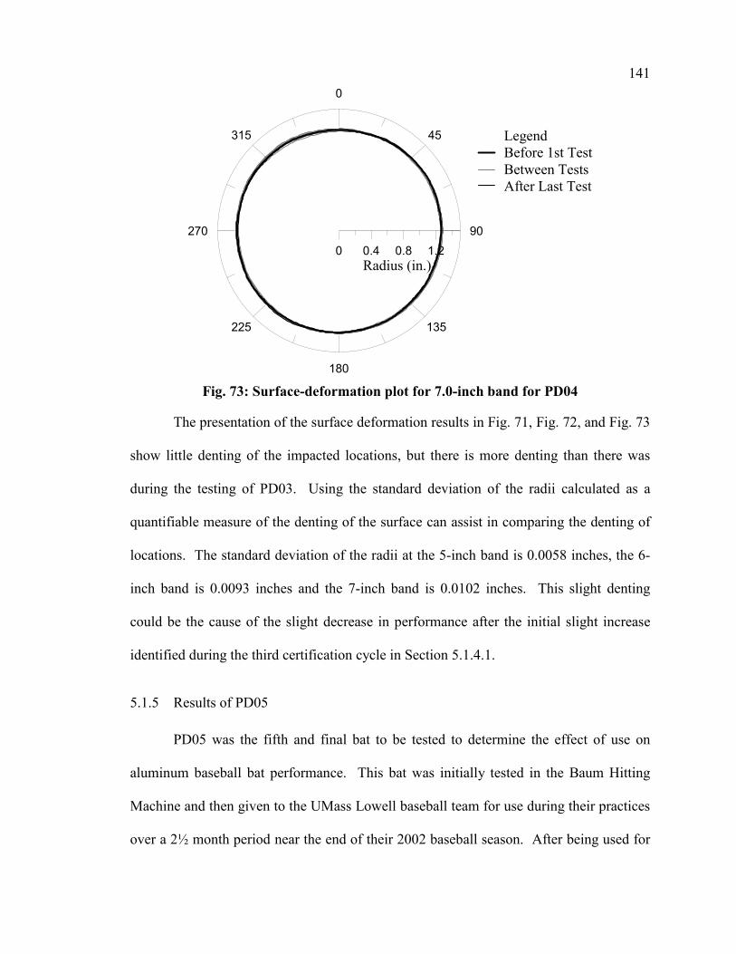
141
0
45
90
135
180
225
270
315
0 0.4 0.8 1.2Radius (in.)
LegendBefore 1st TestBetween TestsAfter Last Test
Fig. 73: Surface-deformation plot for 7.0-inch band for PD04
The presentation of the surface deformation results in Fig. 71, Fig. 72, and Fig. 73
show little denting of the impacted locations, but there is more denting than there was
during the testing of PD03. Using the standard deviation of the radii calculated as a
quantifiable measure of the denting of the surface can assist in comparing the denting of
locations. The standard deviation of the radii at the 5-inch band is 0.0058 inches, the 6-
inch band is 0.0093 inches and the 7-inch band is 0.0102 inches. This slight denting
could be the cause of the slight decrease in performance after the initial slight increase
identified during the third certification cycle in Section 5.1.4.1.
5.1.5 Results of PD05
PD05 was the fifth and final bat to be tested to determine the effect of use on
aluminum baseball bat performance. This bat was initially tested in the Baum Hitting
Machine and then given to the UMass Lowell baseball team for use during their practices
over a 2½ month period near the end of their 2002 baseball season. After being used for

142
2½ months in the field, PD05 was brought back into the lab and the performance testing
was completed again. Like PD02, PD03 and PD04, surface-deformation measurements
were performed prior to and after each of the two certification cycles. The results of the
performance testing are presented in Section 5.1.5.1, and the surface-deformation results
are presented in Section 5.1.5.2.
5.1.5.1 Performance Results of PD05
The same methods of analyzing the data from the testing of PD05 were used as
were used to analyze the other effect-of-use bats. Because there were only two
certification cycles performed, only the control chart and t-test analyses will be presented,
as opposed to the additional presenting of the data alone and the lumped analyses. For
consistency purposes, the graphs in this section for PD05 will use a very similar format to
those used for PD01, PD03 and PD04. Table 3 describes the use of symbols in the plots.
The t-test analysis for all four data methods will be presented in a Table 20. In
this table, the t-test has been used to compare the performance of the initial certification
cycle before the field use to the cycle performed 2½ months later after the completion of
the field use. The t-test gives the probability of the two cycles being from the same
population. The other method uses control charts to compare the data points and their
95% confidence intervals. The control charts will be presented for each of the analysis
cases in Fig. 74, Fig. 75, Fig. 76 and Fig. 77.

143
Table 20: t-test results of probability for PD05
Analysis Method Probability (%) Sweet Spot AEV 69.4 Sweet Spot BESR-based AEV 54.3 Cycle (30 hits) AEV 49.4 Cycle (30 hits) BESR-based AEV 80.1
InitialAfter 2½ months
Time of Testing
93
94
95
96
97
98B
atte
d-B
all V
eloc
ity (m
ph)
Fig. 74: Control chart analysis for AEV of the sweet spot for PD05
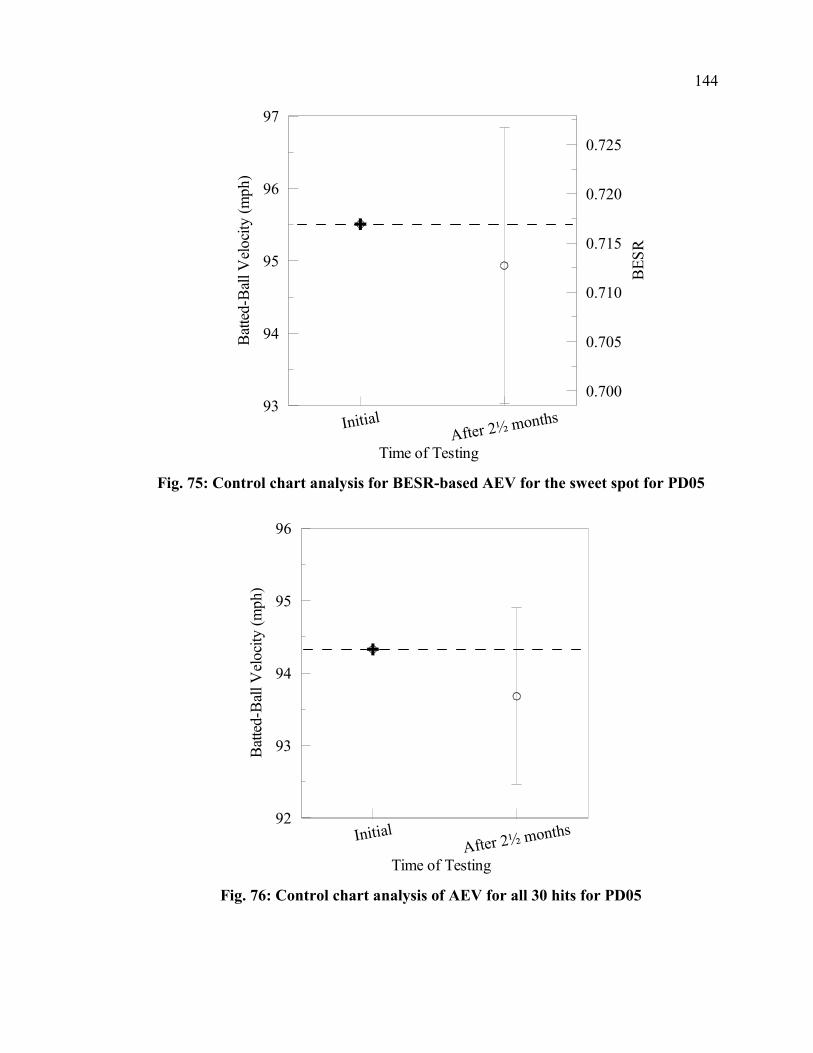
144
InitialAfter 2½ months
Time of Testing
93
94
95
96
97
Bat
ted-
Bal
l Vel
ocity
(mph
)
0.700
0.705
0.710
0.715
0.720
0.725
BES
R
Fig. 75: Control chart analysis for BESR-based AEV for the sweet spot for PD05
InitialAfter 2½ months
Time of Testing
92
93
94
95
96
Bat
ted-
Bal
l Vel
ocity
(mph
)
Fig. 76: Control chart analysis of AEV for all 30 hits for PD05

145
InitialAfter 2½ months
Time of Testing
92
93
94
95
96
Bat
ted-
Bal
l Vel
ocity
(mph
)
0.695
0.700
0.705
0.710
0.715
0.720
BES
R
Fig. 77: Control chart analysis for the BESR-based AEV for all 30 hits for PD05
As can be identified from Fig. 74, Fig. 75, Fig. 76 and Fig. 77, there is an
apparent decrease in performance of PD05 after being used in the field, though the
confidence interval is very large partially because the two certification cycles were
completed using two different lots of baseballs. This lot difference presented a similar
difficulty as was experienced when analyzing the results of PD01. In addition to needing
to use the equations described in Section 4.2 for comparing two set of data with different
baselines, the confidence intervals are larger and therefore give less confidence in the
results that are obtained than those tests using only one lot of baseballs. Table 21
presents a summary of the numerical results formulated in Fig. 74, Fig. 75, Fig. 76 and
Fig. 77.

146
Table 21: Summary of control chart analysis to determine magnitude of change for PD05
Analysis Method Range (mph)
Min (mph)
Max (mph)
Sweet Spot AEV -0.36±1.88 -2.24 1.52 Sweet Spot BESR-based AEV -0.58±1.90 -2.48 1.32
All Hits of Cycle AEV -0.41±1.22 -1.63 0.81 All Hits of Cycle BESR-based AEV -0.15±1.26 -1.41 1.11
Using the analysis performed to generate Fig. 74, Fig. 75, Fig. 76 and Fig. 77 and
assuming that all of these tests are accurate to the limits of the statistical uncertainty and
that they should all reflect the same trend and magnitude, it can be concluded that the
actual change in batted-ball performance of PD05 should fall within the intersection of all
of the ranges presented in Table 21. Therefore, the maximum of the minimums and the
minimum of the maximums becomes the range. Using this basis of analysis, the increase
in performance of PD05 is in the range of -1.4 to 0.8 mph. The average of the four
methods of data analysis shows a 0.4 mph decrease in batted-ball performance calculated
from the mean values in the range column of Table 21.
5.1.5.2 Surface-deformation Results of PD05
Surface-deformation measurements were part of the testing sequence for PD05
occurring before and after both certification cycles. The method and apparatus for
making these measurements are described in Section 3.2.2.2.2. The results obtained from
Eq. 3 are plotted in Fig. 78, Fig. 79 and Fig. 80 using polar coordinates where 0 is equal
to 12 o’clock, 90 is equal to 3 o’clock and so on. The plotting is to actual scale. Like the
testing of PD04, hits in the BHM were taken randomly at all 12 clock positions prior to
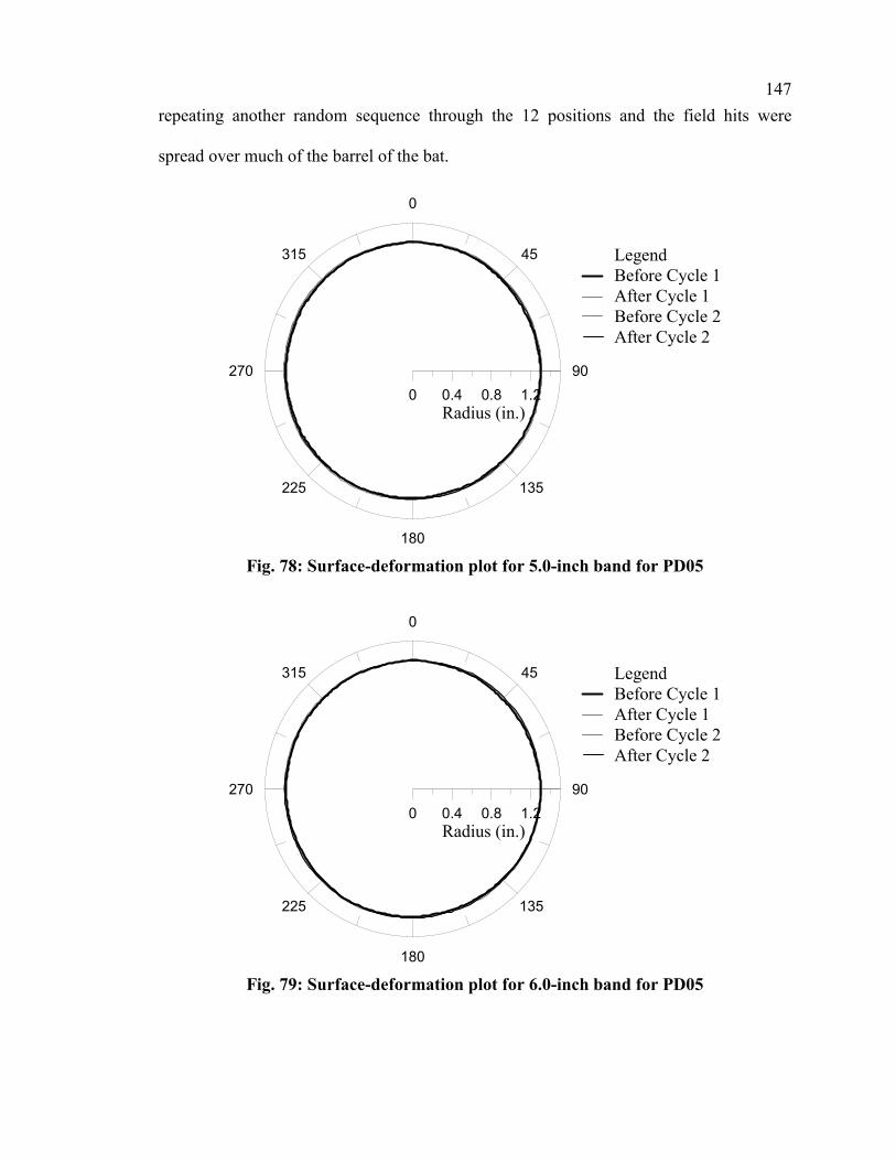
147
repeating another random sequence through the 12 positions and the field hits were
spread over much of the barrel of the bat.
0
45
90
135
180
225
270
315
0 0.4 0.8 1.2Radius (in.)
LegendBefore Cycle 1After Cycle 1Before Cycle 2After Cycle 2
Fig. 78: Surface-deformation plot for 5.0-inch band for PD05
0
45
90
135
180
225
270
315
0 0.4 0.8 1.2Radius (in.)
LegendBefore Cycle 1After Cycle 1Before Cycle 2After Cycle 2
Fig. 79: Surface-deformation plot for 6.0-inch band for PD05
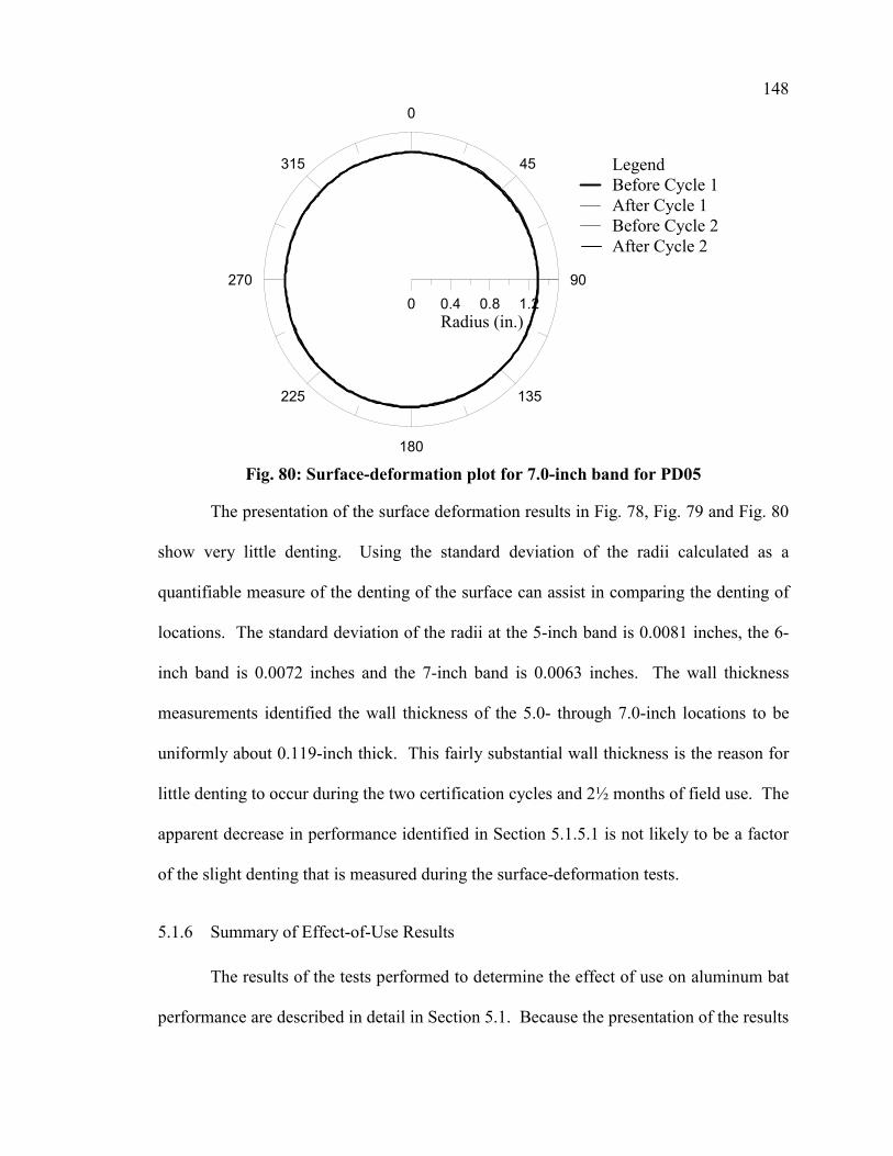
148
0
45
90
135
180
225
270
315
0 0.4 0.8 1.2Radius (in.)
LegendBefore Cycle 1After Cycle 1Before Cycle 2After Cycle 2
Fig. 80: Surface-deformation plot for 7.0-inch band for PD05
The presentation of the surface deformation results in Fig. 78, Fig. 79 and Fig. 80
show very little denting. Using the standard deviation of the radii calculated as a
quantifiable measure of the denting of the surface can assist in comparing the denting of
locations. The standard deviation of the radii at the 5-inch band is 0.0081 inches, the 6-
inch band is 0.0072 inches and the 7-inch band is 0.0063 inches. The wall thickness
measurements identified the wall thickness of the 5.0- through 7.0-inch locations to be
uniformly about 0.119-inch thick. This fairly substantial wall thickness is the reason for
little denting to occur during the two certification cycles and 2½ months of field use. The
apparent decrease in performance identified in Section 5.1.5.1 is not likely to be a factor
of the slight denting that is measured during the surface-deformation tests.
5.1.6 Summary of Effect-of-Use Results
The results of the tests performed to determine the effect of use on aluminum bat
performance are described in detail in Section 5.1. Because the presentation of the results

149
is spread out in many subsections, this section will help to summarize the general results
concluded from the many graphs and tables that were needed to present the results. Table
22 identifies the range of likely increase in performance, the average of the methods of
performance analysis, and the average standard deviation of the calculated localized
radius from the surface-deformation measurements for each of the five bats.
Table 22: Summary of effect-of-use performance tests
Test Range of Increase (mph)
AverageIncrease(mph)
Denting (inches) Comments
PD01 0.8 to 1.8 1.3 n/a Cracking in barrel (830 hits in BHM) PD02 -1.7 to 0.5 -0.6 0.0405 Severe denting (147 hits in BHM) PD03 0.2 to 1.0 0.6 0.0053 Cracking in barrel (806 hits in BHM) PD04 -0.2 to 0.9 0.3 0.0084 Test ended before cracking or denting PD05 -1.4 to 0.8 -0.4 0.0072 Test ended before cracking or denting
5.2 Results of Effect-of-Moisture-Content tests
Effect-of-moisture-content tests were performed using 20 wood baseball bats
supplied by a single company and of the same model. Two different test methods were
employed to help in determining if and by how much the performance of a wood bat will
change with a change in moisture content. The results of the same-weight-method tests
consisted of performance measurements of all 20 bats are presented in Section 5.2.1. The
same-bat-method tests consisted of comparative tests between the same 13 bats being
tested at both lab and higher-moisture-content conditions. These 13 bats had been tested
at one of the conditions during the same-weight-method tests and therefore only needed
to acclimate to the other condition and be tested again. The results from these tests are
presented in Section 5.2.2.
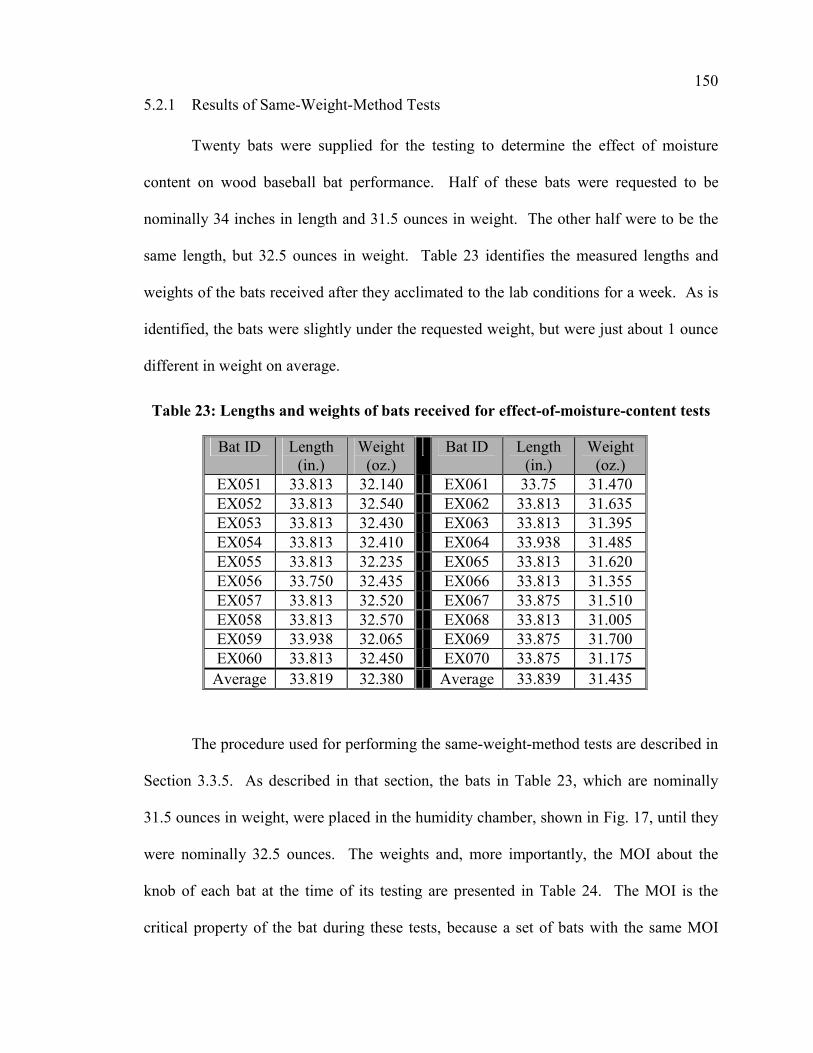
150
5.2.1 Results of Same-Weight-Method Tests
Twenty bats were supplied for the testing to determine the effect of moisture
content on wood baseball bat performance. Half of these bats were requested to be
nominally 34 inches in length and 31.5 ounces in weight. The other half were to be the
same length, but 32.5 ounces in weight. Table 23 identifies the measured lengths and
weights of the bats received after they acclimated to the lab conditions for a week. As is
identified, the bats were slightly under the requested weight, but were just about 1 ounce
different in weight on average.
Table 23: Lengths and weights of bats received for effect-of-moisture-content tests
Bat ID Length (in.)
Weight (oz.)
Bat ID Length (in.)
Weight (oz.)
EX051 33.813 32.140 EX061 33.75 31.470 EX052 33.813 32.540 EX062 33.813 31.635 EX053 33.813 32.430 EX063 33.813 31.395 EX054 33.813 32.410 EX064 33.938 31.485 EX055 33.813 32.235 EX065 33.813 31.620 EX056 33.750 32.435 EX066 33.813 31.355 EX057 33.813 32.520 EX067 33.875 31.510 EX058 33.813 32.570 EX068 33.813 31.005 EX059 33.938 32.065 EX069 33.875 31.700 EX060 33.813 32.450 EX070 33.875 31.175
Average 33.819 32.380 Average 33.839 31.435
The procedure used for performing the same-weight-method tests are described in
Section 3.3.5. As described in that section, the bats in Table 23, which are nominally
31.5 ounces in weight, were placed in the humidity chamber, shown in Fig. 17, until they
were nominally 32.5 ounces. The weights and, more importantly, the MOI about the
knob of each bat at the time of its testing are presented in Table 24. The MOI is the
critical property of the bat during these tests, because a set of bats with the same MOI
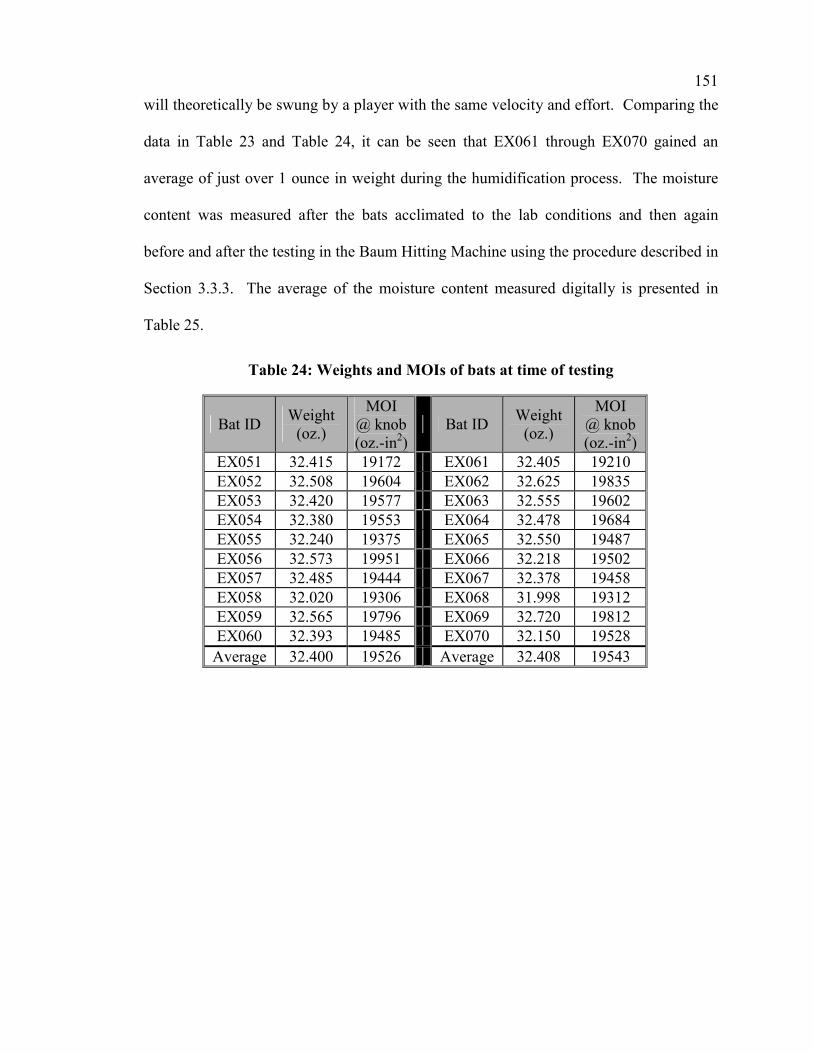
151
will theoretically be swung by a player with the same velocity and effort. Comparing the
data in Table 23 and Table 24, it can be seen that EX061 through EX070 gained an
average of just over 1 ounce in weight during the humidification process. The moisture
content was measured after the bats acclimated to the lab conditions and then again
before and after the testing in the Baum Hitting Machine using the procedure described in
Section 3.3.3. The average of the moisture content measured digitally is presented in
Table 25.
Table 24: Weights and MOIs of bats at time of testing
Bat ID Weight (oz.)
MOI @ knob (oz.-in2)
Bat ID Weight (oz.)
MOI @ knob (oz.-in2)
EX051 32.415 19172 EX061 32.405 19210 EX052 32.508 19604 EX062 32.625 19835 EX053 32.420 19577 EX063 32.555 19602 EX054 32.380 19553 EX064 32.478 19684 EX055 32.240 19375 EX065 32.550 19487 EX056 32.573 19951 EX066 32.218 19502 EX057 32.485 19444 EX067 32.378 19458 EX058 32.020 19306 EX068 31.998 19312 EX059 32.565 19796 EX069 32.720 19812 EX060 32.393 19485 EX070 32.150 19528
Average 32.400 19526 Average 32.408 19543
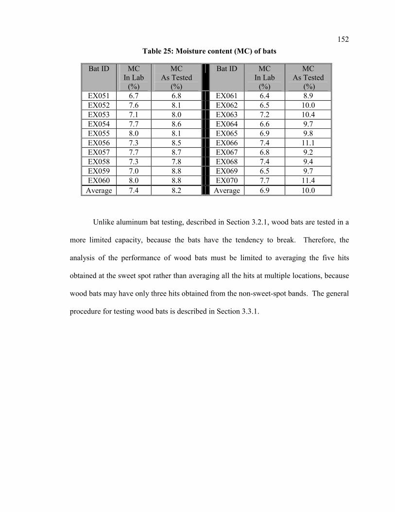
152
Table 25: Moisture content (MC) of bats
Bat ID MC In Lab
(%)
MC As Tested
(%)
Bat ID MC In Lab
(%)
MC As Tested
(%) EX051 6.7 6.8 EX061 6.4 8.9 EX052 7.6 8.1 EX062 6.5 10.0 EX053 7.1 8.0 EX063 7.2 10.4 EX054 7.7 8.6 EX064 6.6 9.7 EX055 8.0 8.1 EX065 6.9 9.8 EX056 7.3 8.5 EX066 7.4 11.1 EX057 7.7 8.7 EX067 6.8 9.2 EX058 7.3 7.8 EX068 7.4 9.4 EX059 7.0 8.8 EX069 6.5 9.7 EX060 8.0 8.8 EX070 7.7 11.4
Average 7.4 8.2 Average 6.9 10.0
Unlike aluminum bat testing, described in Section 3.2.1, wood bats are tested in a
more limited capacity, because the bats have the tendency to break. Therefore, the
analysis of the performance of wood bats must be limited to averaging the five hits
obtained at the sweet spot rather than averaging all the hits at multiple locations, because
wood bats may have only three hits obtained from the non-sweet-spot bands. The general
procedure for testing wood bats is described in Section 3.3.1.
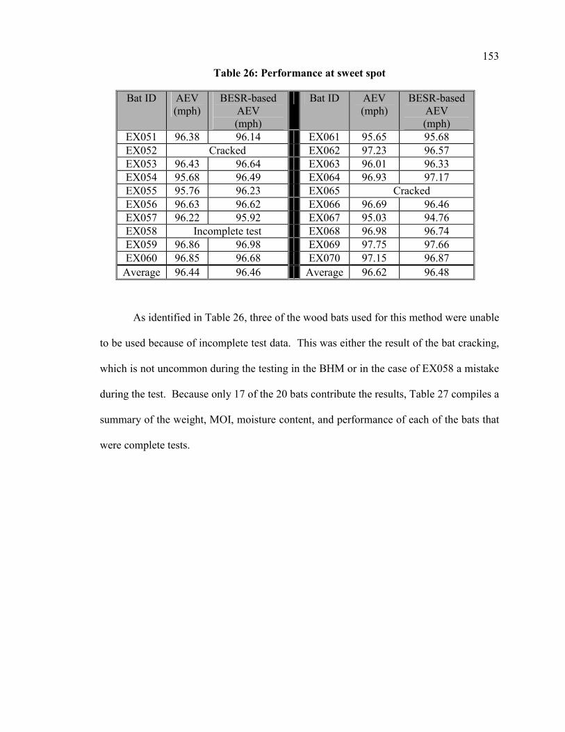
153
Table 26: Performance at sweet spot
Bat ID AEV (mph)
BESR-based AEV (mph)
Bat ID AEV (mph)
BESR-based AEV (mph)
EX051 96.38 96.14 EX061 95.65 95.68 EX052 Cracked EX062 97.23 96.57 EX053 96.43 96.64 EX063 96.01 96.33 EX054 95.68 96.49 EX064 96.93 97.17 EX055 95.76 96.23 EX065 Cracked EX056 96.63 96.62 EX066 96.69 96.46 EX057 96.22 95.92 EX067 95.03 94.76 EX058 Incomplete test EX068 96.98 96.74 EX059 96.86 96.98 EX069 97.75 97.66 EX060 96.85 96.68 EX070 97.15 96.87
Average 96.44 96.46 Average 96.62 96.48
As identified in Table 26, three of the wood bats used for this method were unable
to be used because of incomplete test data. This was either the result of the bat cracking,
which is not uncommon during the testing in the BHM or in the case of EX058 a mistake
during the test. Because only 17 of the 20 bats contribute the results, Table 27 compiles a
summary of the weight, MOI, moisture content, and performance of each of the bats that
were complete tests.

154
Table 27: Same-weight method summary
Bat ID Weight (oz.)
MOI @ knob (oz.-in2)
Moisture Content
(%)
BESR-based AEV (mph)
EX051 32.415 19172 6.8 96.14 EX053 32.420 19577 8.0 96.64 EX054 32.380 19553 8.6 96.49 EX055 32.240 19375 8.1 96.23 EX056 32.573 19951 8.5 96.62 EX057 32.485 19444 8.7 95.92 EX059 32.565 19796 8.8 96.98 EX060 32.393 19485 8.8 96.68
Average 32.434 19544 8.3 96.46 EX061 32.405 19210 8.9 95.68 EX062 32.625 19835 10.0 96.57 EX063 32.555 19602 10.4 96.33 EX064 32.478 19684 9.7 97.17 EX066 32.218 19502 11.1 96.46 EX067 32.378 19458 9.2 94.76 EX068 31.998 19312 9.4 96.74 EX069 32.720 19812 9.7 97.66 EX070 32.150 19528 11.4 96.87
Average 32.392 19549 10.0 96.47
The purpose of this section of the thesis is to determine if there is an effect on
wood-baseball-bat performance with a change in moisture content. The same-weight-
method tests examine a variety of bats that are of the same length and model and have
different moisture contents. Fig. 81 and Fig. 82 represent the performance data from the
sweet spot for each bat with respect to its average moisture content. Each bat is
identified in Fig. 81 and Fig. 82 by a single data point and the uncertainty of the
measured values. This uncertainty is the standard deviation of the mean based on the 5
hits at the sweet spot and the measurements of moisture content. The bold data point in
each of these figures represents the average of all of the bats from each moisture content
condition. The error bars on the bold data represent the uncertainty for each condition.

155
6 7 8 9 10 11 12Moisture Content (%)
93
94
95
96
97
98
99
Bat
ted-
Bal
l Vel
ocity
(mph
)
Fig. 81: Measured AEV from sweet spot as function of moisture content
6 7 8 9 10 11 12Moisture Content (%)
93
94
95
96
97
98
99
Bat
ted-
Bal
l Vel
ocity
(mph
)
0.700
0.705
0.710
0.715
0.720
0.725
0.730
0.735
0.740
BES
R
Fig. 82: BESR-based AEV from sweet spot as function of moisture content
156
Fig. 81 and Fig. 82 show no significant change in performance on average. The
variation from bat to bat among wood bats is almost 3 mph under these test conditions.
Using the AEV, the average increase from the moderate moisture content to the high
moisture content is 0.18 mph. When taking into consideration the variations of the
inbound velocities of the ball and the bat, the BESR-based AEV shows only a 0.02-mph
increase from the moderate to the high moisture content. The magnitude of this change is
much smaller than the uncertainty of the averages because of the relatively large scatter
among performance of wood bats.
5.2.2 Results of Same-Bat-Method Tests
Of the twenty bats that were supplied for the testing to determine the effect of
moisture content on wood baseball bat performance, three bats cracked during the initial
phase that took place as part of the same-weight-method tests and four more bats cracked
during a second round of testing that took place as part of the same-bat-method tests.
The remaining 13 bats were exposed to two complete wood bat certification cycles at two
different moisture contents. The benefit of this comparison relies on the fact that the
same bats were tested at different moisture contents, and therefore, the variability
between different bats is essentially eliminated. The negative aspect to of these tests is
that the MOI of each bat during the tests is different and therefore the bat is not swung at
the same speed. Using the procedures and equations described in Section 4.1.4, the
relationship between the measured weights and the change in MOI are calculated and
presented in Table 28. The moisture contents during both tests of each bat are presented
in Table 29. These moisture contents are the average of all 16 digital readings recorded
before and after each test.

157
Table 28: Weights of bats as tested and predicted change in MOI between tests
Bat ID Weight
Lab condition (oz.)
Weight humidified
(oz.)
∆W (oz.)
∆MOI @ knob (oz.-in.2)
EX051 32.395 33.300 0.905 452 EX053 32.420 33.330 0.910 455 EX054 32.367 33.260 0.893 446 EX055 32.220 33.160 0.940 470 EX056 32.385 33.425 1.040 520 EX057 32.475 33.520 1.045 522 EX059 32.545 33.775 1.230 615 EX060 32.390 33.435 1.045 522 EX061 31.705 32.400 0.695 346 EX062 31.780 32.605 0.825 412 EX063 31.675 32.555 0.880 440 EX064 31.820 32.465 0.645 323 EX070 31.315 32.150 0.835 419
Average 32.115 33.029 0.914 457
Table 29: Moisture contents of bats
Bat ID MC
Lab condition (%)
MC Humidified
(%) EX051 6.8 10.8 EX053 8.0 10.1 EX054 8.6 11.9 EX055 8.1 12.1 EX056 8.5 11.5 EX057 8.7 12.4 EX059 8.8 11.7 EX060 8.8 11.9 EX061 7.2 8.9 EX062 7.9 10.0 EX063 8.3 10.4 EX064 7.4 9.7 EX070 8.2 11.4
Average 8.1 11.0
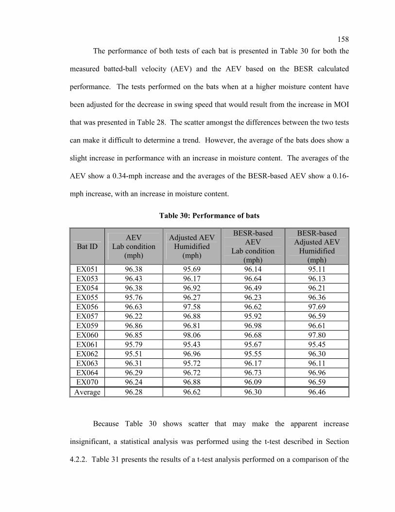
158
The performance of both tests of each bat is presented in Table 30 for both the
measured batted-ball velocity (AEV) and the AEV based on the BESR calculated
performance. The tests performed on the bats when at a higher moisture content have
been adjusted for the decrease in swing speed that would result from the increase in MOI
that was presented in Table 28. The scatter amongst the differences between the two tests
can make it difficult to determine a trend. However, the average of the bats does show a
slight increase in performance with an increase in moisture content. The averages of the
AEV show a 0.34-mph increase and the averages of the BESR-based AEV show a 0.16-
mph increase, with an increase in moisture content.
Table 30: Performance of bats
Bat ID AEV
Lab condition (mph)
Adjusted AEV Humidified
(mph)
BESR-based AEV
Lab condition (mph)
BESR-based Adjusted AEV
Humidified (mph)
EX051 96.38 95.69 96.14 95.11 EX053 96.43 96.17 96.64 96.13 EX054 96.38 96.92 96.49 96.21 EX055 95.76 96.27 96.23 96.36 EX056 96.63 97.58 96.62 97.69 EX057 96.22 96.88 95.92 96.59 EX059 96.86 96.81 96.98 96.61 EX060 96.85 98.06 96.68 97.80 EX061 95.79 95.43 95.67 95.45 EX062 95.51 96.96 95.55 96.30 EX063 96.31 95.72 96.17 96.11 EX064 96.29 96.72 96.73 96.96 EX070 96.24 96.88 96.09 96.59
Average 96.28 96.62 96.30 96.46
Because Table 30 shows scatter that may make the apparent increase
insignificant, a statistical analysis was performed using the t-test described in Section
4.2.2. Table 31 presents the results of a t-test analysis performed on a comparison of the

159
results from each test on each bat. The t-test gives the probability that the samples of
data are from the same population, i.e. no external factor affecting the performance.
Among these probabilities are a few that are low, but nothing that opposes the normal
scatter associated with the analysis. On average there was a 50% chance that the bats had
no change in performance.
Table 31: T-test of results for each bat
Bat ID AEV
Probability (%)
BESR-based AEV Probability
(%) EX051 41.4 28.0 EX053 59.3 39.1 EX054 51.4 79.4 EX055 48.9 88.2 EX056 10.0 17.9 EX057 54.5 54.5 EX059 95.6 65.5 EX060 21.5 29.6 EX061 65.0 77.2 EX062 8.1 34.1 EX063 56.3 96.4 EX064 61.3 79.4 EX070 49.5 59.8
Average 47.9 57.6
Table 32 is a brief analysis of the averages from each same-bat method test. In
statistics there is a t-test that can be used when there is a pairing of the data. In the case
of this test, there is a pairing of the same bats being tested as part of both moisture-
content levels. The paired t-test performs a more rigorous comparison of the data
samples. The results of this paired t-test are presented in Table 32.

160
Table 32: Paired t-test of results for same-bat-method
AEV Probability
(%)
BESR-based AEV Probability
(%) 9.5 40.4
5.2.3 Summary of Effect-of-Moisture-Content Results
The results of the tests performed to determine the effect of an increase in
moisture content on wood bat performance are described in detail in Section 5.2. This
section will help to summarize the general results concluded from the graphs and tables
that were needed to present the results. Table 33 identifies the averages of increase in
performance and the number of bats used within the method to obtain the results.
Table 33: Summary of effect-of-increased-moisture-content performance tests
Method Average
Performance Increase
Number of Bats Used
Same-Weight-Method 0.18 and 0.02 8 of 9 Same-Bat-Method 0.34 and 0.16 13 of 13

161
6 Conclusions
In conclusion, the effects of use and moisture content on baseball bat performance
are very small. The tests performed to determine the effect of use on aluminum bat
performance showed a small increase of as much as 1.3 mph when the bat showed
essentially no denting, but when denting occurred, the performance of the bat dropped by
just over ½ mph. Though an increase to the performance was thought to be the result of
an increase in hardness, microhardness tests identified the increase in performance to be
connected to a decrease in hardness. The effect-of-moisture-content tests performed on
wood bats showed no significant change in performance. Both methods used showed a
slight increase of under ½ mph. Statistical methods were employed to determine if the
average increases were statistically significant. For the effect-of-use tests, the increase
was determined to be statistically significant, but for the effect-of-moisture-content tests
the increase was not statistically significant.

162
7 RECOMMENDATIONS
This thesis has attempted to answer the questions:
• Is there an effect to the performance of an aluminum bat resulting
from the use of the bat over its lifetime?
• Is there an effect to the performance of a wood bat resulting from a
change in moisture content?
Though this thesis has begun to answer these questions through extensive testing,
fully understanding these principles will take continued research of the topics. This
section will present a few recommendations for future testing, modeling and analysis, if
these properties wish to be better understood.
• Effect of Use on Aluminum Baseball Bat Performance
Is the cause of the change in performance a factor of a change in material
properties or a change in the surface geometry of the bat? To help to determine the
dependence of the change in performance on the surface geometry of the bat, finite
element analysis could be performed using the impact of a baseball model with a model
of several different bat geometries similar to those in the surface deformation plots for
PD02 in Fig. 34, Fig. 35 and Fig. 36. If the material properties remain constant, these
models could isolate the potential change resulting sole from the change in the geometry
of the surface of the barrel.
163
Additionally, what is the effect to the performance of some of the other aluminum
and composite bats? This thesis was limited to the study of fairly standard aluminum
bats without the use of composite layers or connecting pieces. To more fully understand
how the effect of use may affect the game, these other styles of bat would have to be
tested. Based on the methods used in this thesis to determine the effect of use on
aluminum bat performance, it would be recommended to use a test similar to the testing
of PD04 and PD05 to conduct more tests on different styles of non-wood bats. This
recommendation is primarily based on the fact that the all-in-machine tests take too much
machine time to obtain the results. These tests could be performed in cooperation with
the NCAA and college baseball teams. The bats could be tested prior to the beginning of
the season, one or more times during the middle of the season and then at the end of the
season. For increased statistical significance, two certification cycles could be completed
at each testing time if it were determined to be cost-effective.
• Effect of Moisture Content on Wood Baseball Bat Performance
Is there a change in performance of a wood bat from a change in moisture content
if the bat is dried out rather than humidified? In this thesis, wood bats were tested at
normal lab conditions of 70 degrees Fahrenheit and 50% Relative Humidity and elevated-
humidity conditions that resulted in a one-ounce-weight increase. No significant change
in the performance was identified with this change in moisture content. It is anticipated
from the results of this thesis that moisture content does not play a significant role in the
performance of a wood bat, but further testing at a dried condition could be helpful to
prove this effect for a full range of moisture contents. These tests could be performed
using the same methodology except the bats would be stored for a time in either a

164
dehumidification chamber or possibly in a normal non-humidified room during the winter
months.
Is there an effect to the durability of wood bats resulting from a change in
moisture content? This question was not addresses by the testing in this thesis, because
the main focus of the thesis was to examine performance effects. Because it appears that
the performance is not affected when the moisture content is changed, the potential
change of the durability of wood bats may be very important to know when selecting the
best way to buy, care for and use a wood bat. Because the Baum Hitting Machine exerts
greater forces on the handle of a bat during the initial part of the swing and after the
impact, it is not the best way to measure durability. To measure durability a combination
of field testing and 3-point-bend testing could be used. The 3-point-bend tests could be
performed on the bats while supported at the nodes of the first vibrational mode or on bat
billets or cut samples or regular shapes (i.e. cylinders or square prisms) that are
humidified or dehumidified the same as the bats have been.
165
8 LITERATURE CITED Adair, R.K. 1994. The Physics of Baseball. HarperCollins, New York, pp. 108-111 ASTM. 1989. “Standard Test Method for Measuring Microhardness of Materials”.
Designation E384-89. Annual Book of ASTM Standards. American Society of Testing and Materials. West Conshohocken, PA.
ASTM. 1998. “Standard Test Method for Measuring Baseball Bat Performance Factor”.
Designation F1881-98. Annual Book of ASTM Standards. American Society of Testing and Materials. West Conshohocken, PA.
ASTM. 2002. “Standard Test Methods for Rockwell Hardness and Rockwell Superficial
Hardness of Metallic Materials”. Designation E18-02. Annual Book of ASTM Standards. American Society of Testing and Materials. West Conshohocken, PA.
Baum, C.S. 1999. “Sports implement testing methods and apparatus - Patent Number
5,988,861”. United States Patent and Trademark Office. www.uspto.gov. Blankenhorn. 2002. Dr. Paul Blankenhorn of Penn. State. Personal Communications.
June 26. Britannica. 1911. “Base-ball”. The 1911 Edition - Encyclopedia.
http://1911encyclopedia.org/B/BA/index.htm, 23-Jan-03. Brody, H. 1986. “The sweet spot of a bat”. American Journal of Physics 54, pp. 640-643 Carroll, M.M. 2000. “Assessment and regulation of baseball bat performance”.
Symposium on Trends in the Application of Mathematical Mechanics, edited by P.E. O’Donoghue and J.N. Flavin (Elsevier, Amsterdam). p. 17.
Courtney, T.H. 2000. Mechanical Behavior of Materials. Second Edition. The McGraw-
Hill Companies, Inc. Boston. pp. 179-181. Crisco, J.J. and Greenwald, R.M. 2000. “Metal baseball bats can out perform wood bats
with a similar ‘sweet spot’” Twenty-fourth Annual Meeting of the American Society of Biomechanics. Chicago. http://asb-biomech.org/onlineabs/abstracts2000/pdf/170.pdf
Cross, R. 1998. “The sweet spot of a baseball bat”. American Journal of Physics 66, pp.
772-779.

166
Cross, R. 1999. “Impact of a ball with a bat or racket”. American Journal of Physics 67 (8). pp. 692-702.
Encyclopedia. 2003. “Baseball”. Encyclopedia.com
http://www.encyclopedia.com/html/section/baseball_history.asp, 23-Jan-03. Fleisig, G.S., Zheng, N., Stodden, D.F. and Andrews, J.R. 2002. “Relationship between
bat mass properties and bat velocity”. Sports Engineering 5. Kirkpatrick, P. 1963. “Batting the ball”. American Journal of Physics 31. pp. 606-613. Lerner, L.S. 1996. Physics for Scientists and Engineers. Jones and Bartlett Publishers
Inc., Boston. pp. 308-309. Lindberg, V. 2000. “Uncertainties and Error Propagation - Part I of a manual on
Uncertainties, Graphing, and the Vernier Caliper”. http://www.rit.edu/~vwlsps/uncertainties/Uncertaintiespart2.html
Little League. 2003. “Little League Baseball Historical Timeline - 1971”. Little League
Website. http://www.littleleague.org/history/index.htm, 23-Jan-03. Louisville. 2003. “Then & Now – Timeline”. Louisville Slugger Museum.
http://www.sluggermuseum.org/flash5.html, 23-Jan-03. McNamee, M. 2003. “Great Moments in Easton History”. Easton Sports Inc. Personal
Communication. 27-Feb-03. Montgomery, D.C., Runger, G.C. and Hubele, N.F. 1998. Engineering Statistics. John
Wiley and Sons, Inc. New York. Mustone, T.J. and Sherwood, J.A. 1998. "Using LS-DYNA to Characterize the
Performance of Baseball Bats". 5th International LS-DYNA Users Conference, September 21-22. Southfield, MI.
Nathan, A.M. 2000. “Dynamics of the baseball-bat collision”. American Journal of
Physics 68 (11). pp. 979-990. Nathan, A.M. 2001. “Baseball and Bat Performance Standards”. PowerPoint Talk before
the NCAA Research Committee, June 13. Omaha, NE. pp. 4-8. Nathan, A.M. 2003. “Characterizing the performance of baseball bats”. American Journal
of Physics 71 (2). pp 134-143. NCAA. 1999. “National Collegiate Athletic Association Provisional Standard for Testing
Baseball Bat Performance”. NCAA News Releases, September 29. http://www.ncaa.org/releases/makepage.cgi/miscellaneous/1999092901ms.htm

167
Shenoy, M.M., Smith, L.V. and Axtell, J.T. 2001. “Performance assessment of wood,
metal, and composite baseball bats”. Composite Structures 52. pp. 397-404. SportsLine. 2003. “CWS History – 1974”. CBS SportsLine Website.
http://cbs.sportsline.com/u/ce/feature/0,1518,2384656_39,00.html, 23-Jan-03. Watts, R.G. and Bahill, A.T. 1990. Keep Your Eye On The Ball: The Science and
Folklore of Baseball. W.H. Freeman and Company, New York, pp.1-12 Watts, R.G. and Bahill, A.T. 2000. Keep Your Eye On The Ball: Curveballs,
Knuckleballs, and Fallacies of Baseball. W.H. Freeman and Company, New York. Wheeler, A.J. and Ganji, A.R. 1996. Introduction to Engineering Experimentation.
Prentice Hall, Inc. Upper Saddle River. pp. 136. Wood Handbook, 1999, Wood Handbook: Wood as an Engineering Material. Forest
Products Laboratory. US Department of Agriculture, Forest Service, Madison, WI.
Worth. 2003. “The History of Bats”. Worth Sports Website.
http://www.worthsports.com/aboutworth/bat_history.html, 23-Jan-03.
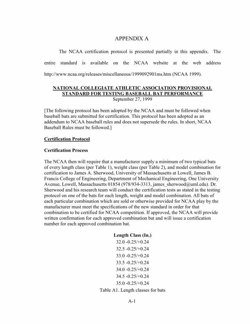
A-1
APPENDIX A
The NCAA certification protocol is presented partially in this appendix. The
entire standard is available on the NCAA website at the web address
http://www.ncaa.org/releases/miscellaneous/1999092901ms.htm (NCAA 1999).
NATIONAL COLLEGIATE ATHLETIC ASSOCIATION PROVISIONAL STANDARD FOR TESTING BASEBALL BAT PERFORMANCE
September 27, 1999
[The following protocol has been adopted by the NCAA and must be followed when baseball bats are submitted for certification. This protocol has been adopted as an addendum to NCAA baseball rules and does not supersede the rules. In short, NCAA Baseball Rules must be followed.]
Certification Protocol
Certification Process
The NCAA then will require that a manufacturer supply a minimum of two typical bats of every length class (per Table 1), weight class (per Table 2), and model combination for certification to James A. Sherwood, University of Massachusetts at Lowell, James B. Francis College of Engineering, Department of Mechanical Engineering, One University Avenue, Lowell, Massachusetts 01854 (978/934-3313, [email protected]). Dr. Sherwood and his research team will conduct the certification tests as stated in the testing protocol on one of the bats for each length, weight and model combination. All bats of each particular combination which are sold or otherwise provided for NCAA play by the manufacturer must meet the specifications of the new standard in order for that combination to be certified for NCAA competition. If approved, the NCAA will provide written confirmation for each approved combination bat and will issue a certification number for each approved combination bat.
Length Class (In.) 32.0 -0.25/+0.24 32.5 -0.25/+0.24 33.0 -0.25/+0.24 33.5 -0.25/+0.24 34.0 -0.25/+0.24 34.5 -0.25/+0.24 35.0 -0.25/+0.24
Table A1. Length classes for bats

A-2
Weight Class (oz.)
(Unit difference from length) -3.00 to -2.10 -2.09 to -1.10 -1.09 to -0.10
Table A2. Weight classes for bats without grip
A mandatory silk-screen or other permanent certification mark shall consist of the phrase "BESR Certified" and must be clearly displayed on the barrel end of the bat. The manufacturer may use the certification mark in descriptive materials (such as catalogs) to identify bats that comply with this testing standard, but may make no other use of the mark. Use of the certification mark to advertise or promote the sale or distribution of bats is expressly prohibited. There shall be no charge for the use of the certification mark in accordance with this protocol.
In the event that all bats submitted for testing become damaged and unusable for testing, the manufacturer will be notified by the Certification Center and requested to submit at least two more bats for certification. The certification of that length, weight and model combination will then go to the next open position in the certification queue, i.e. end of the line, upon receipt of the new bats.
All bats will be returned except for the tested bat(s) and one for record purposes. The retained bats will be stored in a secure area and only Certification Center personnel will have access to the secure area. The manufacturer will be assured that the confidentiality of its bat is protected.
Testing Protocol
Bat Preparation Procedures
1. Measure and record location of balance point, model, length and weight. 2. Draw impact lines and axis line. 3. Measure and record diameter at 3", 4", 5", 6", 7", 8" and 9" from the tip of the
barrel and 8" from the base of the knob. 4. Drill safety-pin hole at 1-7/16" from the base of the knob.
Mounting in the BHM
Mount in grip, lock with safety pin 1-7/16" from base of the knob such that the rotation axis is 5-7/16" from the base of the knob, and align axis of bat with ball center. The grip material will be astroturf. The grip material will be uniform from test to test, and no set of grip material will be used for more than 8 hours of continuous testing. The grip material will be allowed to relax for a minimum of 8 hours before being reused.

A-3
Bat-Swing and Ball Pitch Speeds
Input target speeds of 66+1 mph for the bat swing speed (velocity measured at a point 6 inches from the barrel end) and 70+2 mph ball speed to yield a combined speed of 136 + 3 mph. The tolerance on individual input speeds is to allow for test variance on a dynamic hitting machine (Baum Hitting Machine).
Torque Cutoff to Coast
The torque supplied to the bat by the servo is cutoff 12.8 inches prior to impact. This torque cutoff ensures that the bat is coasting through the bat/ball collision as opposed to being powered through the collision. This 12.8-in. specification is accomplished by using a pot value of 0.32 in the servo-control program, where each 0.01 of pot setting equates to 0.4-in. Therefore, because the bat speed may vary from test to test, the coast time will likewise vary from test to test, but the coast distance is fixed to be 12.8-in.
Determination of a Valid Hit
For a reading to be valid, ball exit speed as measured at the 72" speed-gate location must be less than the higher of the speeds as measured at the 9" and 13" light-cell positions. The pitch speed must be within +2 mph and the swing speed must be within +1 mph of their respectively prescribed values. The combined speed must be within +3 mph of its prescribed value.
The bat speed on the datasheet is measured at the impact location. This impact location is not always at the 6-inch position on the bat. Therefore, the swing speed to conclude whether or not the hit was valid needs to reflect the appropriate speed at the point of contact for a swing speed of 66 mph at the 6-inch location. The following formula calculates the ideal swing speed at the point of contact:
Vcontact = 66 x (Length - 5.375 - Location) / (Length - 11.375)
Where V is bat speed at the 6-inch location, Vcontact is the bat speed as recorded on the test datasheet, Length is the overall length of the bat, and Location is the hit location, e.g. 6.5-inch, or 7.0 inch, etc. A valid swing speed must be within Vcontact+1.
The ball must pass through the exit hole and not be too far left or right or high or low. The target is 62-1/16 in. from the impact point. The target is a diamond with equal diagonals of 13-in, i.e. a square, as shown in Fig. A1. One diagonal is horizontal and parallel to the bat axis. Three strings hang in the target for judging ball position manually. One string hangs from the top center of the diamond and extends to the horizontal diagonal. Parallel strings hang +2 in. on either side of the centerline string. If a ball hits the left string, then it is described as being "too far left". If a ball hits the right string, then it is described to be "too far right". If the center of the ball is judged by the test operator to be >+2 in. below the horizontal centerline of the target, then it is described as "too

A-4
low". If the center of the ball is judged by the test operator to be >+2 in. above the horizontal centerline of the target, then it is described as "too high".
13.00-in
13.00-in
2.50-in 2.50-in
Target Holein Wall
Back Wallof BHM
Strings
Fig. A1 BHM target window
Exit-Velocity Readings and Impact Location
All bat positions are measured with respect to the distance from the tip of the barrel. Raw data exit velocities are to be recorded with testing commencing at the 6" point. Bat profiling will continue with hits at the 5", then the 7" points. If deemed necessary for certification purposes, bat profiling will continue at the discretion of the certification personnel with hits at additional points by using 1" and/or 0.5" increments. Five (5) consecutive valid exit-velocity readings are to be recorded at each of the bat-axis impact locations. Consecutive valid readings will be determined without regard to any interspersed invalid readings; thus, for example, three valid readings, followed by an invalid reading, followed by two valid readings will be considered five consecutive valid readings. The total number of hits may vary from bat to bat.
The ball exit speed ratio (BESR) is defined by:
BESR = [v* - (V-v) / 2] / (V+v)
where v and v* are the ball entry and exit speeds, respectively, and V is the bat entry speed (this is the speed at the 6" point on the bat). Therefore, the measured bat input

A-5
speed should be adjusted accordingly to reflect the bat input speed at the 6" point by use of the formula:
V = Vcontact x (Length - 11.375) / (Length - 5.375 - Location)
Where V is bat entry speed at the 6-inch location, Vcontact is the bat entry speed as recorded on the test datasheet, Length is the overall length of the bat, and Location is the hit location, e.g. 6.5 in. or 7.0 in.
This relationship will be used to normalize the data with respect to bat and ball input speed variations. The BESR shall be the average of five valid readings at the point of maximum velocity as discussed above. At the point of maximum exit velocities, an average of 5 valid hits is used to conclude legality. If at anytime during the certification process the average of 5 consecutive valid hits exceeds the limiting BESR, then testing is halted and the bat is concluded to be illegal for NCAA competition. [Note: The wood bat standard will be based on at least three valid hits at each of the three above impact locations.]
The NCAA is continuing to study the issue of work-hardening in nonwood bats. At this time, the protocol will not contain specifications that attempt to address the issue of work-hardening, and none will be enforced before Aug. 1, 2000. However, if research reveals solid evidence related to this phenomenon, the protocol may be changed in the future in an effort to take the effects of work-hardening into account in the certification process.
The nonwood bats will be randomly rotated prior to each hit. The wood bats will be rotated 180 degrees prior to each hit according to standard wood bat usage, i.e. Iabel up and label down. Alignment of the bat will be checked before each hit.
Length-to-Weight Unit Differential
The length-to-weight unit differential of each nonwood bat shall not exceed three units without the grip. Each length-class and weight-class combination of a particular model must be certified for compliance.
Bat Surface
The surface of the bat tested for certification must be the same as that of the production bat model which it represents and may exclude graphics.
Bat Diameter
The barrel diameter shall be no greater than 2.625 inches. A certified bat ring (no more than 1/4-inch thick) with an interior diameter of 2.657 inches must pass completely over the length of each bat prior to each hit. If the ring fails to pass over the entire length of the bat, then the bat is concluded to be illegal for NCAA competition.
A-6
Balance Point
There is no specification for the center of gravity, a.k.a. the balance point. However, the balance point will be recorded.
Baseball Specifications
The ball shall have a weight of 5.12+0.035 oz. The circumference of the ball shall be 9.05+0.05 in.
In a lot of I44 baseballs, six (6) will be randomly selected and tested to ensure that ball compression is no greater within a reasonable range than the compression characteristics of balls used in previous testing during August and September, 1999. If any one ball fails to meet this compression standard, then the entire lot is concluded to be unusable for certification testing. The six (6) balls tested will not be used for bat testing.
All baseballs to be used for certification will be tested on the BHM and the exit velocity will be recorded. The balls will be hit on the logo panel with the 6-in. point of a 34/31 Baum AAA Pro bat with a 2.5" diameter and a mass moment of inertia greater than 680 lb-in2 at (70+2 mph pitch)+(68+1 mph swing speed @6" point)=138+3 mph. Baseballs for certification testing must fall within the acceptable exit velocity range (94+1.5 mph).
The initial BESR standard was generated using the Rawlings R100 NCAA ball, which qualified to a nominal speed of 94 mph using the standard bat at 70/68. In the event that the baseball is changed to a nominal speed other than 94 mph by some amount x, then the BESR will be recalculated using the wood-bat database where the batted ball speeds will be adjusted by this amount x, e.g.
BESR = [(v*+x) - (V-v) / 2] / (V+v)
X will have a negative value if the nominal speed drops below 94 mph.
If new balls are utilized in future testing, the characteristics of those balls will be taken into consideration to ensure that no bat or type of bat is disadvantaged by the change in balls. Testing of balls to recalculate the maximum BESR shall be performed utilizing Baum bats of the same model and with the same characteristics described above. A change in BESR resulting from a change in balls shall not render previously compliant bats noncompliant. Any such change shall not materially alter the margin of compliance for compliant bats.
Ball Impacts
Each of the test baseballs used during certification tests will be impacted a maximum of eight times (two sets of impacts on four opposite panels). Hitting will commence with the logo panel.

A-7
Bat Preparation
Bats will be brought to laboratory environment temperature prior to testing.
Baseball Preparation
Baseballs shall be stored in the laboratory environment for at least 24 hours prior to testing. Baseballs shall be stored in airtight containers. The balls shall be weighed again just prior to testing. Baseballs must meet the weight and circumference specifications in order to be used.
Laboratory Environment
The temperature in the testing lab shall be 75+10°F and a relative humidity of 45+15%.
Manufacturer Attendance
Manufacturer attendance is optional. Outside observers representing the organization that submitted the bat for testing may be present, but must follow the directions of the certification operators.
Pass-Fail Criteria
The bat must meet the size and weight specifications.
There are no tolerances for length-weight ratio (no greater than three units without the grip) or maximum barrel diameter.
The bat ring must pass over the entire length of the bat before and after every hit.
The ball exit speed ratio (BESR) as determined from the average of 5 consecutive valid hits at the maximum velocity location as described above must not exceed the stated BESR limit.
The bat’s BESR must be less than .728 (which corresponds to 97 mph).

B-1
APPENDIX B
This appendix includes some of the portions of the patent that regulate the use of
the Baum Hitting Machine. Included are primarily the abstract and the summary of the
information. The claims, which constitute the more legal aspects of the patent, have not
been included but can be found on the United States Patent and Trademark Office
(USPTO) website, www.uspto.com (Baum 1999).
United States Patent 5,988,861 Baum November 23, 1999
Sports implement testing methods and apparatus
Abstract
Methods and apparatus for testing a striking-type sports implement such as a bat is disclosed. In terms of apparatus, a system according to the invention includes a bat-swinging module, a ball-delivery module, and one or more programmed computers. The bat-swinging module includes means to grip a bat at its handle end, and an independent, computer servo-controlled motor to swing the bat. The ball-delivery module includes a ball support and a second, independent, computer servo-controlled motor to place the ball into the swing of the bat along a delivery path such that the bat is able to strike the ball and cause the ball to travel along a precise trajectory path. Various sensors are disposed to measure swing speed, "pitch" speed and exit velocity, with the computer(s) being operative to construct a database of bat performance characteristics based upon swing speed, pitch speed and exit velocity, and display selected portions of the database in accordance with a user input.
Inventors: Baum; Charles S. (Traverse City, MI) Assignee: Baum Research & Development Co., Inc. (Traverse City, MI) Appl. No.: 761707 Filed: December 6, 1996

B-2
FIELD OF THE INVENTION The present invention relates generally to sports equipment testing and, more particularly, to a system and methods for testing the performance of a striking implement such as a baseball bat or racket in conjunction with a ball or other associated projectile. BACKGROUND OF THE INVENTION There is an outstanding need in professional sports to quantify the performance of the equipment involved, and to provide tools to evaluate the performance of existing devices. At the present time, for example, the evaluation of bats, balls, and so forth, is almost completely dependent on the experience and observations of the players who use such equipment. These observations are supported only by an imperically derived historical database of performance statistics. Other than radar guns to measure ball velocity and video cameras for player viewing, there are no quantitative measures of ball movement(s), bat performance, etc. The need remains, therefore, for an analysis and testing system which may be used to monitor the swing of a striking type sports implement such as a bat as it strikes a ball, and to gather information as to swing speed, projectile delivery, and exit velocity. Such information may be used to create performance databases for a variety of analytical and/or statistical evaluations. When used as an input into implement manufacturing, the results obtained from the system may also be used to maximize player safety, for example, by ensuring that exit velocity does not exceed a predetermined threshold. SUMMARY OF THE INVENTION The present invention provides methods and apparatus for testing striking-type sports implements. Although many of the descriptions contained herein relate to baseball batting, the system is equally applicable to sports which use rackets or mallets and projectiles other than round balls. Thus, the invention may be used to test and evaluate equipment associated with softball, tennis, squash, badminton, and other sports. Broadly, a testing process according to the invention comprises the steps of mechanically swinging the striking implement along a predetermined swing path while delivering the ball or other appropriate projectile along a predetermined delivery path and into the swing path such that it is struck and enters a flight path. As this occurs, one or more of the following are measured: the swing speed of the implement, the delivery speed of the projectile and the exit velocity of the projectile. Preferably the swing speed of the implement and the delivery speed of the projectile are measured near a point proximate to the point of striking contact, whereas exit velocity is preferably measured at a plurality of points along the flight path, not only to determine speed, but also to determine and use angular displacement along the trajectory for a more accurate reading. Based upon these measurements, a programmed computer is used to develop, compile and/or display performance characteristics, such as the ability of different implements to produce a given exit velocity as a function of projectile type, delivery speed, swing speed, and so forth.

B-3
With specific regard to baseball, a hardware embodiment of a batting machine according to the invention includes a bat-swinging module, a ball-delivery module, and one or more programmed computers. Preferably, a main computer is used for data acquisition and analysis purposes as discussed above, with a second computer being dedicated to bat-swing and ball-delivery module control, thereby off-loading the main computer of tasks associated with bat and ball timing, speed and contact-point coordination. A bat-swinging module according to the invention includes means to grip a bat at its handle end, and an electromotive source to swing the bat. A ball-delivery module may include a ball support and a different electromotive source operative to place the ball into the swing of the bat along a delivery path, enabling the bat to strike the ball and cause the ball to travel along a trajectory path. The electromotive sources are preferably implemented as computer-controlled servo motors, with the second computer being used to develop and deliver appropriate control signals to the motors to effectuate a highly accurate and predictable interaction between the bat and ball and a consistent flight path. In a preferred arrangement, the ball delivery module includes a swing arm terminating in a fork with upper and lower members between which the ball is supported. The use of a fork shape enables the bat to swing between the upper and lower members while accurately adjusting the contact point. The ball support itself may either includes means for actively releasing the ball immediately prior to contact through the use of computer-controlled solenoid release switches. Alternatively, a break-away structure may be used which automatically releases the ball when struck. Different structures of this type are disclosed, including a two-piece arrangement having upper and lower cradles, and a one-piece unit having a central aperture within which the ball is carried. In preferred embodiments, these break-away structures are composed primarily of lightweight foam to minimize their impact on the various measurements. A bat-swing sensor is used to output a signal carrying information associated with the swing speed of the bat. A ball-delivery speed sensor, disposed along the delivery path, is used to output a signal carrying information relating to the velocity of the ball, that is the "pitch" speed. In the preferred embodiment, a plurality of sensors are used to accurately determine exit velocity, with a first set of sensors being used to determine initial exit velocity as a function of angular displacement. In response to an operator input, the main computer activates a hitting sequence mediated by the second computer while monitoring the signals output by the various sensors for data acquisition and analysis purposes. By selecting the sensed values indicative of the highest exit velocity, the system is able to automatically obtain accurate measurements despite slightly curved or angled trajectories, whatever the reason for such departures from a `perfect` flight path. The automated batting machinery and methods just described may be used in conjunction with a swing tester and an automated manufacturing process, both of which are also described herein. In the case of the swing tester, a human player is used to test a

B-4
particular implement. For example, regard to baseball, a ball is positioned on a vertical, non-rigid support, with sensors on either side being used to measure bat swing and ball speed to determine a range of potential performance criteria, which may then be fed into the hitting machine for a much more refined analysis, including the ability to set more appropriate swing speeds. In terms of automated manufacturing, as the performance characteristics are developed according to the invention, the information derived may be fed into a forming process to create an implement with specific performance range or restrictions. For example, in the case of a baseball bat, with knowledge of certain physical characteristics of the starting blank or "billet," such as material composition, size, weight, center of gravity, density, and so forth, the information obtained from the hitting machine may be input to an automated lathe or other automatically controlled formation apparatus to create a bat exhibiting a particular performance aspect or range of behavioral attributes. This input to automated manufacturing is also applicable to non-wooden, composite, and metal implements, including aluminum bats, graphite rackets, and so forth. The combination of the swing tester, which may be used to determine a particular range of performance capabilities, the hitting machine, which may be used to analyze a highly refined set of performance criteria, and the automated manufacturing processes may be used cooperatively to form a closed loop linking the capabilities of a human player to an end product having extremely exacting performance capabilities. ---------------------------------------------------------------------------------------------------------- For the complete patent and figures search patent number 5,988,861 on the United States Patent and Trademark Office website at www.uspto.gov.
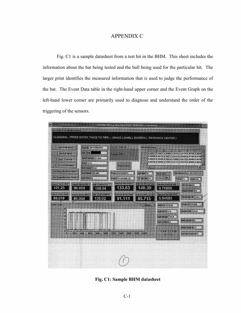
C-1
APPENDIX C
Fig. C1 is a sample datasheet from a test hit in the BHM. This sheet includes the
information about the bat being tested and the ball being used for the particular hit. The
larger print identifies the measured information that is used to judge the performance of
the bat. The Event Data table in the right-hand upper corner and the Event Graph on the
left-hand lower corner are primarily used to diagnose and understand the order of the
triggering of the sensors.
Fig. C1: Sample BHM datasheet
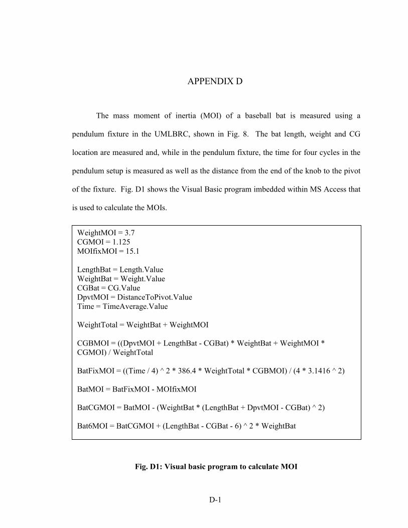
APPENDIX D
The mass moment of inertia (MOI) of a baseball bat is measured using a
pendulum fixture in the UMLBRC, shown in Fig. 8. The bat length, weight and CG
location are measured and, while in the pendulum fixture, the time for four cycles in the
pendulum setup is measured as well as the distance from the end of the knob to the pivot
of the fixture. Fig. D1 shows the Visual Basic program imbedded within MS Access that
is used to calculate the MOIs.
WeightMOI = 3.7 CGMOI = 1.125 MOIfixMOI = 15.1 LengthBat = Length.Value WeightBat = Weight.Value CGBat = CG.Value DpvtMOI = DistanceToPivot.Value Time = TimeAverage.Value WeightTotal = WeightBat + WeightMOI CGBMOI = ((DpvtMOI + LengthBat - CGBat) * WeightBat + WeightMOI * CGMOI) / WeightTotal BatFixMOI = ((Time / 4) ^ 2 * 386.4 * WeightTotal * CGBMOI) / (4 * 3.1416 ^ 2) BatMOI = BatFixMOI - MOIfixMOI BatCGMOI = BatMOI - (WeightBat * (LengthBat + DpvtMOI - CGBat) ^ 2) Bat6MOI = BatCGMOI + (LengthBat - CGBat - 6) ^ 2 * WeightBat
D-1
Fig. D1: Visual basic program to calculate MOI

E-1
APPENDIX E
Requirements for a Valid Hit:
1) Inbound ball velocity must be measured to be 70 ± 2 mph
2) Inbound bat velocity must be measured to be 66 ± 1 mph at the 6-inch location or
equivalent, where the target velocity is defined by the following equation depending
on the location
)375.11()375.5(66
−−−⋅=
lLlVC
where: VC is Target Bat-in velocity at impact location in mph
l is Bat Length in inches
L is Location of impact in inches (e.g. 5.0-inch or 6.5-inch)
3) The baseball must be hit on target through the diamond shaped hole with a 13-inch
diagonal. The ball must be in the per per, per high, per low, per left, or per right
region according to Fig. 2 in Section 2.3.
4) The higher of the two batted-ball velocity measurements from the 9- to 10-inch and
13- to 14-inch distances must be higher than the check-cell-velocity measurement
made using the Oehler speed gates located at the 6- to 9-feet location.

APPENDIX F Moisture Content Test Data Worksheet
Bat ID: _________ Inventory #: ______-____ Purpose: __________________________________________ Date: ____________ Person performing measurements: ___________________ Person performing BHM Test: ______________________ Step 1) Remove Bat from Storage Location Storage Location: ____________________________ Duration in Storage Location: __________________ Conditions in Storage Location: RH:____% Temp:____oF Time of Removal: __________ Step 2) Profile the bat (normal method) (MOI by Hand) Page Number: _____ Step 3) Measure Moisture Content of Bat Digital: Side 1: ______ to ______ Side 2: ______ to ______ Side 3: ______ to ______ Side 4: ______ to ______ Analog: In Logo: ______%MC Step 4) Measure Bat Weight Immediately Prior to Loading Bat into BHM Weight: ________ oz Time: __________ Step 5) Wrap Bat with Strapping Tape and Load into BHM Time of Finished Loading: ________ Step 6) Normal Wood Bat Certification (66/70) Condition of Bat: Good / Hairline Crack / Crack / Broken Time of Certification Completion: _______ Step 7) Measure Bat Weight After Unwrapping Bat Weight: _______ oz Time: _________ Step 8) Measure Moisture Content of Bat Digital: Side 1: ______ to ______ Side 2: ______ to ______ Side 3: ______ to ______ Side 4: ______ to ______ Analog: In Logo: ______%MC Step 9) Profile the bat (normal method) (MOI by Hand) Sheet Number: _____ Step 10) Place in New Storage Location Location: _________________ Future Purpose: _______________________________
F-1
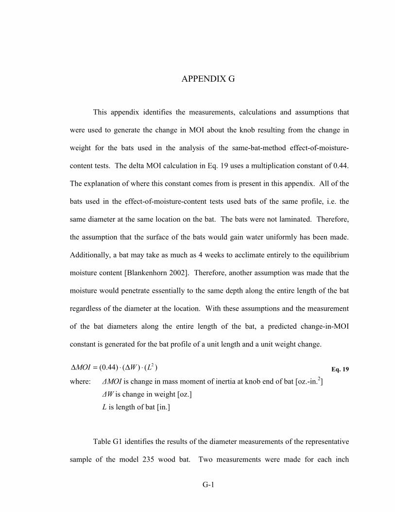
G-1
APPENDIX G
This appendix identifies the measurements, calculations and assumptions that
were used to generate the change in MOI about the knob resulting from the change in
weight for the bats used in the analysis of the same-bat-method effect-of-moisture-
content tests. The delta MOI calculation in Eq. 19 uses a multiplication constant of 0.44.
The explanation of where this constant comes from is present in this appendix. All of the
bats used in the effect-of-moisture-content tests used bats of the same profile, i.e. the
same diameter at the same location on the bat. The bats were not laminated. Therefore,
the assumption that the surface of the bats would gain water uniformly has been made.
Additionally, a bat may take as much as 4 weeks to acclimate entirely to the equilibrium
moisture content [Blankenhorn 2002]. Therefore, another assumption was made that the
moisture would penetrate essentially to the same depth along the entire length of the bat
regardless of the diameter at the location. With these assumptions and the measurement
of the bat diameters along the entire length of the bat, a predicted change-in-MOI
constant is generated for the bat profile of a unit length and a unit weight change.
)()()44.0( 2LWMOI ⋅∆⋅=∆ Eq. 19
where: ∆MOI is change in mass moment of inertia at knob end of bat [oz.-in.2]
∆W is change in weight [oz.]
L is length of bat [in.]
Table G1 identifies the results of the diameter measurements of the representative
sample of the model 235 wood bat. Two measurements were made for each inch

G-2
location, one in the radial direction and the other in the tangential direction. The radial
direction is defined as the direction across the grains, and the tangential direction is
defined as the direction through the grains. Fig. G1 may better show these directions.
Table G1 also shows the average of the measurements in the two directions.
Fig. G1: Description of radial and tangential directions on wood bat
Table G2 uses the information from Table G1 to calculate the MOI for each inch
long section based on a unit length bat and a unit weight change. The MOI about the
knob of the bat is of interest; therefore the length of the bat has been divided into 1-inch
increments, located their average distances from the knob. The diameters for the two
ends of each section have been averaged and this average was then used to calculate a
surface area for each section. Both the location and surface area of each section were
then scaled by the length and total surface area respectively as to make the bat’s length 1
unit of length and the surface area 1 unit of length squared. Because the moisture is
assumed to be uniform based on surface area, the scaling of the surface area is equal to
scaling the increase of moisture to 1 unit of weight. Therefore, the sum of the last
Rad
ial D
irect
ion
Tangential Direction

G-3
column in Table G2 is able to generate the change in MOI for a bat of 1 unit length and a
weight change of 1 unit of weight. The sum of these numbers is 0.44. Therefore, for a
wood bat with the profile of model 235 and the assumed distribution of the increase of
moisture, the MOI change is defined by Eq. 19.

G-4
Table G1: Diameter measurements along surface of wood bat (model 235)
Bat Location From Barrel End
(inches)
Diameter Radial Direction
(inches)
Diameter Tangential Direction
(inches)
Diameter Average (inches)
0* 2.559 2.550 2.555 1 2.559 2.550 2.555 2 2.523 2.514 2.519 3 2.497 2.480 2.489 4 2.460 2.451 2.456 5 2.408 2.399 2.404 6 2.360 2.360 2.360 7 2.316 2.311 2.314 8 2.263 2.260 2.262 9 2.195 2.191 2.193 10 2.137 2.123 2.130 11 2.029 2.014 2.022 12 1.883 1.893 1.888 13 1.746 1.734 1.740 14 1.615 1.608 1.612 15 1.508 1.496 1.502 16 1.382 1.382 1.382 17 1.310 1.300 1.305 18 1.227 1.235 1.231 19 1.157 1.157 1.157 20 1.105 1.100 1.103 21 1.074 1.061 1.068 22 1.015 1.015 1.015 23 0.956 0.957 0.957 24 0.918 0.918 0.918 25 0.896 0.883 0.890 26 0.885 0.874 0.880 27 0.891 0.888 0.890 28 0.892 0.888 0.890 29 0.930 0.927 0.929 30 0.983 0.974 0.979 31 1.078 1.067 1.073 32 1.272 1.271 1.272 33 1.570 1.559 1.565 34* 2.100 2.100 2.100
* represents an assumed value
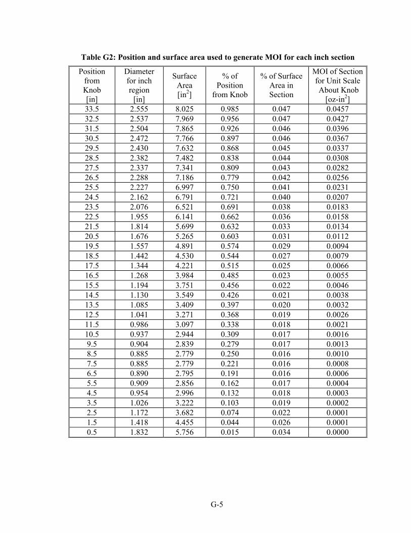
G-5
Table G2: Position and surface area used to generate MOI for each inch section
Position from Knob [in]
Diameter for inch region
[in]
Surface Area [in2]
% of Position
from Knob
% of Surface Area in Section
MOI of Section for Unit Scale About Knob
[oz-in2] 33.5 2.555 8.025 0.985 0.047 0.0457 32.5 2.537 7.969 0.956 0.047 0.0427 31.5 2.504 7.865 0.926 0.046 0.0396 30.5 2.472 7.766 0.897 0.046 0.0367 29.5 2.430 7.632 0.868 0.045 0.0337 28.5 2.382 7.482 0.838 0.044 0.0308 27.5 2.337 7.341 0.809 0.043 0.0282 26.5 2.288 7.186 0.779 0.042 0.0256 25.5 2.227 6.997 0.750 0.041 0.0231 24.5 2.162 6.791 0.721 0.040 0.0207 23.5 2.076 6.521 0.691 0.038 0.0183 22.5 1.955 6.141 0.662 0.036 0.0158 21.5 1.814 5.699 0.632 0.033 0.0134 20.5 1.676 5.265 0.603 0.031 0.0112 19.5 1.557 4.891 0.574 0.029 0.0094 18.5 1.442 4.530 0.544 0.027 0.0079 17.5 1.344 4.221 0.515 0.025 0.0066 16.5 1.268 3.984 0.485 0.023 0.0055 15.5 1.194 3.751 0.456 0.022 0.0046 14.5 1.130 3.549 0.426 0.021 0.0038 13.5 1.085 3.409 0.397 0.020 0.0032 12.5 1.041 3.271 0.368 0.019 0.0026 11.5 0.986 3.097 0.338 0.018 0.0021 10.5 0.937 2.944 0.309 0.017 0.0016 9.5 0.904 2.839 0.279 0.017 0.0013 8.5 0.885 2.779 0.250 0.016 0.0010 7.5 0.885 2.779 0.221 0.016 0.0008 6.5 0.890 2.795 0.191 0.016 0.0006 5.5 0.909 2.856 0.162 0.017 0.0004 4.5 0.954 2.996 0.132 0.018 0.0003 3.5 1.026 3.222 0.103 0.019 0.0002 2.5 1.172 3.682 0.074 0.022 0.0001 1.5 1.418 4.455 0.044 0.026 0.0001 0.5 1.832 5.756 0.015 0.034 0.0000

H-1
APPENDIX H
Analysis to show Gaussian distribution of BHM performance data
In order to use many of the statistical methods that have been employed in this
thesis, it needs to be known if the data that is being analyzed is of a Gaussian or normal
distribution. This can be best accomplished by looking at a large set of data from the
Baum Hitting Machine and using a histogram plot. The data from PD03 is extensive and
has no significant increase after the third certification cycle. Therefore, this analysis will
use the data from cycles 4 through 26 giving 575 total data points and assume very little
change in performance with use. These 575 data points are recorded from five different
locations on the bat and those locations have different performances. Therefore, to
account for these different performances the data has been adjusted by the difference
between the average of the data from each location and the average of all of the data from
the five locations. After each data was scaled, it was sorted into 22 evenly spaced
sections along the entire range of the data. The results of this sectioning are presented in
Table H1 and Fig. H1.
Additionally, the data was compared against the ranges of the average plus and
minus 1, 2, and 3 standard deviations (σ). The standard deviation was calculated to be
1.50 mph for the 575 data points and the average is 95.78 mph. The percentage of data
points that were in the 1σ range is 72.0%, the 2σ range is 95.0%, and the 3σ range is
99.0%. These values compare very well to the ideal Gaussian values of 68.3%, 95.4%,
and 99.7%, respectively.

H-2
Table H1. Number of data points counted in each range
Range Count
91.00 to 91.49 1
91.50 to 91.99 1
92.00 to 92.49 3
92.50 to 92.99 7
93.00 to 93.49 13
93.50 to 93.99 34
94.00 to 94.49 43
94.50 to 94.99 66
95.00 to 95.49 85
95.50 to 95.99 96
96.00 to 96.49 69
96.50 to 96.99 51
97.00 to 97.49 41
97.50 to 97.99 31
98.00 to 98.49 9
98.50 to 98.99 7
99.00 to 99.49 3
99.50 to 99.99 4
100.00 to 100.49 8
100.50 to 100.99 1
101.00 to 101.49 1
101.50 to 101.99 1

H-3
0
10
20
30
40
50
60
70
80
90
100
91 92 93 94 95 96 97 98 99 100
101
Adjusted batted-ball velocity ranges (mph)
Num
ber o
f dat
a po
ints
in ra
nge
Fig. H1. Histogram of adjusted data points for cycles 4 through 26 of PD03
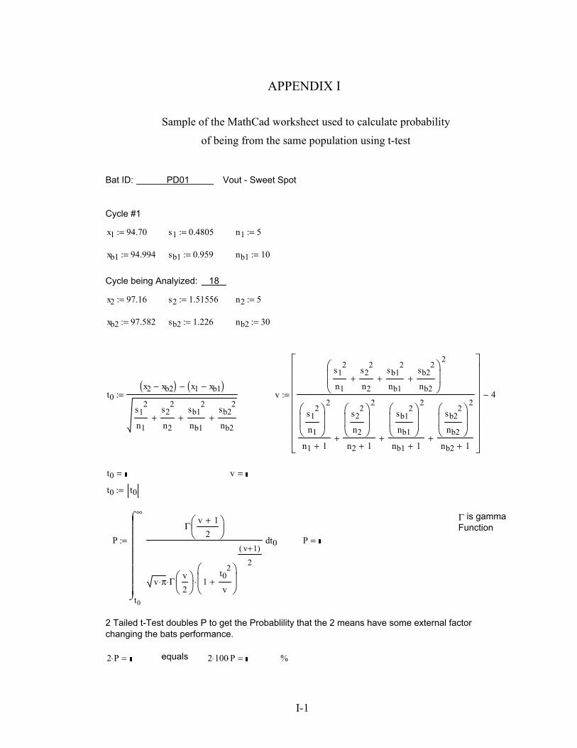
I-1
APPENDIX I
Sample of the MathCad worksheet used to calculate probability
of being from the same population using t-test
%2 100⋅ P⋅ =equals2 P⋅ =
2 Tailed t-Test doubles P to get the Probablility that the 2 means have some external factor changing the bats performance.
P =P
t0
∞
t0
Γv 1+
2
v π⋅ Γv2
⋅ 1t0
2
v+
v 1+( )
2
⋅
⌠⌡
d:=
Γ is gamma Function
t0 t0:=
v =t0 =
v
s12
n1
s22
n2+
sb12
nb1+
sb22
nb2+
2
s12
n1
2
n1 1+
s22
n2
2
n2 1++
sb12
nb1
2
nb1 1++
sb22
nb2
2
nb2 1++
4−:=t0x2 xb2−( ) x1 xb1−( )−
s12
n1
s22
n2+
sb12
nb1+
sb22
nb2+
:=
nb2 30:=sb2 1.226:=xb2 97.582:=
n2 5:=s2 1.51556:=x2 97.16:=
Cycle being Analyized: 18
nb1 10:=sb1 0.959:=xb1 94.994:=
n1 5:=s1 0.4805:=x1 94.70:=
Cycle #1
Bat ID: PD01 Vout - Sweet Spot

BIOGRAPHICAL SKETCH OF AUTHOR
Patrick Drane has lived in Norton, Massachusetts since his birth in Attleboro, MA
on October 26, 1978. After graduating from Norton High School, he began attending the
University of Massachusetts Lowell in September 1996. While an undergraduate at
UMass Lowell, Patrick participated in the honors program, the college newspaper, the
marching band, the engineering student council, and a number of other activities.
Additionally he was inducted into three honor societies, Alpha Lambda Delta, Tau Beta
Pi, and Pi Tau Sigma, serving as president in Alpha Lambda Delta and Tau Beta Pi.
While working towards his degrees he worked two summers as an intern at Accutech
Packaging designing molds for thermoforming processing and two summers as an intern
at Albany International Research Company primarily developing FEA models. After
completing his Bachelors in Mechanical Engineering in 2000, Patrick continued at
UMass Lowell as a graduate student. During his time as a graduate student he worked as
a teaching assistant for several junior level labs and as a research assistant and manager
in the UMass Lowell Baseball Research Center. With the completion of this thesis
Patrick graduated with a Master’s Degree in Mechanical Engineering in 2003.