characterization of porous tio2 surfaces formed on 316l stainless steel by plasma electrolytic
TRANSCRIPT

J. Funct. Biomater. 2012, 3, 349-360; doi:10.3390/jfb3020349
Journal of
Functional Biomaterials
ISSN 2079-4983 www.mdpi.com/journal/jfb/
Article
Characterization of Porous TiO2 Surfaces Formed on 316L Stainless Steel by Plasma Electrolytic Oxidation for Stent Applications
Zhiguang Huan, Lidy E. Fratila-Apachitei *, Iulian Apachitei and Jurek Duszczyk
Department of BioMechanical Engineering, Delft University of Technology, Mekelweg 2,
Delft 2628 CD, The Netherlands; E-Mails: [email protected] (Z.H.); [email protected] (I.A.);
[email protected] (J.D.)
* Author to whom correspondence should be addressed; E-Mail: [email protected];
Tel.: +31-15-2789083; Fax: +31-15-2786730.
Received: 20 March 2012; in revised form: 25 April 2012 / Accepted: 27 April 2012 /
Published: 11 May 2012
Abstract: In this study, a porous oxide layer was formed on the surface of 316L stainless
steel (SS) by combining Ti magnetron sputtering and plasma electrolytic oxidation (PEO)
with the aim to produce a polymer-free drug carrier for drug eluting stent (DES)
applications. The oxidation was performed galvanostatically in Na3PO4 electrolyte. The
surface porosity, average pore size and roughness varied with PEO treatment duration, and
under optimum conditions, the surface showed a porosity of 7.43%, an average pore size of
0.44 µm and a roughness (Ra) of 0.34 µm. The EDS analyses revealed that the porous layer
consisted of Ti, O and P. The cross-sectional morphology evidenced a double-layer
structure, with a porous titania surface and an un-oxidized dense Ti film towards the
interface with 316L SS. After the PEO treatment, wettability and surface free energy
increased significantly. The results of the present study confirm the feasibility of forming a
porous TiO2 layer on stainless steel by combining sputtering technology and PEO. Further,
the resultant porous oxide layer has the potential to be used as a drug carrier for DES, thus
avoiding the complications associated with the polymer based carriers.
Keywords: drug eluting stent; plasma electrolytic oxidation; titanium oxide layer; stainless
steel; surface porosity
OPEN ACCESS

J. Funct. Biomater. 2012, 3
350
1. Introduction
In recent years, the combination of stents, able to inhibit recoil and negative tissue remodeling with
drugs that inhibit neointimal hyperplasia has emerged as a highly promising alternative to reduce in-stent
restenosis in the treatment of atherosclerosis [1,2]. These drug eluting stents (DES) consist mostly of a
metallic scaffold and a polymer coating which contains drugs. As the drugs are released from the coating
after implantation, the rates of restenosis are substantially reduced by inhibition of cells’ proliferation, as
revealed by numerous large clinical trials [3,4]. Despite the advantages over bare metal stents, the
incidence of late stent thrombosis and the development of late restenosis have raised issues about the
long-term safety and efficacy of DES [5,6]. Both late occurring complications have been related to the
characteristics of the polymer matrix, which can cause a marked inflammatory response leading to
incomplete re-endothelialization and neointimal proliferation after completion of drug release [7].
To avoid the complications associated with polymer-based DES, development of polymer-free
drug-eluting stents is desirable. From a biomedical point of view, titanium oxide (TiO2) surfaces with
their excellent biochemical stability and blood compatibility can be a promising alternative to polymer
matrices [8–10]. Therefore, it is suggested that a TiO2 layer can protect a metallic stent from direct
contact with the vessel wall after drug elution is completed.
In this study, porous TiO2 layers have been produced on a 316L stainless steel substrate, which is
the most commonly used material for cardiovascular stents, by sputtering a titanium film on the
substrate that was subsequently oxidized by plasma electrolytic oxidation (PEO). Deposition of a valve
metal on steel by different methods followed by PEO has been previously used for formation of
protective coatings [11,12]. Plasma electrolytic oxidation is an electrochemical method used to
produce porous oxide layers on valve metals and their alloys [13,14]. The process occurs at high
voltages (above the breakdown voltages) and the characteristics of the porous layers may be controlled
by adjusting the process parameters. The process has been applied to enhance surface biofunctionality
of titanium alloys used in orthopedic and dental implants [15,16], while its application for the
fabrication of DES is rare. Therefore, the purpose of the current study was to evaluate the feasibility of
PEO to produce porous polymer-free drug carriers for DES.
2. Experimental Section
2.1. Sample Preparation and PEO Treatment
Samples of 8 cm × 1 cm × 0.1 cm were cut from a 316L stainless steel (SS) sheet and were
successively cleaned in acetone, ethanol and deionized water for 10 min each. Then the specimens
were coated with a Ti film of 5 µm thickness by magnetron sputtering. The as-coated samples are
denoted as 5-Ti-SS.
Prior to the PEO treatment, the as-coated samples were ultrasonically cleaned in acetone and
deionized water. PEO was carried out in a double-wall glass electrolytic cell with a volume of 800 mL.
The samples were screwed to an insulated metallic rod and suspended in the centre of the electrolytic
cell as anode, surrounded by a cylindrical steel cathode. As an electrolyte, a solution of 0.04 M
tri-sodium phosphate (Na3PO4) was used that was cooled during the process by circulation of cooling
water (10 °C) through the electrolytic cell jacket using an external thermostat. Agitation of the

J. Funct. Biomater. 2012, 3
351
electrolyte was maintained at a speed of 500 rpm using a magnetic stirrer (Ika, NL). PEO was
performed under galvanostatic conditions at a current density of 5 A/dm2. During the oxidation
process, the voltage was automatically recorded, and the oxidation time was up to 40 min to get an
overview of the relationship between the oxidation time and the PEO response. After selected
durations, the process was stopped and the resultant samples were thoroughly cleaned with deionized
water, dried using blowing air and stored in desiccator until further testing.
2.2. Surface Characterization
After sputter coating for enhanced conductivity, the surface morphology of the oxidized samples was
examined by scanning electron microscopy (SEM, JSM-6500F, JEOL) using an accelerating voltage of
5 kV. The elemental composition was estimated on the surface and cross-section by an energy dispersive
X-ray spectrometer (EDS, INCA Energy, Oxford Instruments) coupled with the SEM equipment. To
observe the 316L/Ti and Ti/TiO2 interfaces, the cross section images of the specimens were also
investigated. Further, the oxide layer’s thickness was measured directly from the cross section images of
the specimens. A Taylor-Hobson Surtronic 3+ surface texture-meter was used to determine the average
surface roughness (Ra) of the samples. Ten random measurements were taken for each sample followed
by statistical analysis to determine the mean Ra value. Pore’s diameter was measured from SEM images
using the Photoshop® software based on which surface porosity was estimated.
The dynamic advancing contact angles were determined with a Krüss DSA 100 drop shape analyzer
using deionized water and diiodomethane. A volume of 10 µL liquid was placed automatically on the
tested surface using a microlitre syringe. Upon contact with the surface the increasing droplet profile
was measured at 1 s intervals for 33 s. For every sample, triplicate measurements were performed in
the two different wetting liquids. Surface free energy was calculated according to Fowkes’ theory. The
values reported represent the average and standard deviations for contact angles in water and total
surface free energy.
2.3. Statistics
The experimental values were analyzed using the Student’s t-test and are expressed as the mean
values ± standard deviation (SD). A p-value < 0.05 was considered statistically significant.
3. Results and Discussion
3.1. Voltage-Time Responses during the PEO Process
The evolution of voltage with the PEO treatment time is shown in Figure 1. During the initial 180 s
of PEO treatment, the voltage-time responses revealed a slow voltage rise probably due to preferential
initial oxide growth at the fine flaws on the sputtered surface representing the easiest path for the
current flaw. The voltage then rose rapidly to about 160 V indicating formation of a dielectric barrier
layer with high electric resistance. As the PEO treatment continued the voltage increased further,
however with a reduced slope. When the anodic voltage reached a value of ca. 220 V, large numbers
of small sparks were observed to move rapidly and randomly across the surface of the oxide film
indicative of dielectric breakdown due to impact ionisation [14,17,18]. The size of the sparks increased

J. Funct. Biomater. 2012, 3
352
with prolonged PEO treatment, while their density and moving speed decreased so that at about 250 V
they became almost immobile. The maximum voltage reached was 280 V after which it started to
slowly decrease indicating that layer growth could not be sustained anymore. Apart from the initial
region of low slope, the voltage-time response followed the general trend found when bulk titanium
substrates are PEO treated in phosphate-based solutions [17,19].
Figure 1. Voltage transients during plasma electrolytic oxidation (PEO) of 5-Ti-SS
samples in Na3PO4 electrolyte at a current density of 5 A/dm2.
It is known that under galvanostatic conditions, the characteristics of the porous layers can vary
with PEO treatment duration as a function of sparks morphology, density, mobility and
intensity [14,20,21], and the gas released through the locally softened material [17]. It is therefore of
interest to evaluate layer properties at different voltages during the PEO process. In this study, the
evolution of surface morphology was assessed at 220 V, 250 V and 280 V, and the focus was on
porosity, pore size and pore density, which are considered important for the potential application as
drug carriers for drug eluting stents.
3.2. Surface Morphology and Chemical Composition of the PEO Layers
The surface morphology of the layers formed on the titanium sputtered stainless steel substrate during
the PEO at the three different voltages selected is shown in Figure 2. The stainless steel was completely
covered by a dense Ti layer showing fine grain size and some larger agglomerates distributed
homogeneously on the surface (Figure 2a). The surface morphology of the sample at 200 V is shown in
Figure 2b as representative for the PEO stage between 150 and 220 V. It can be seen that very tiny pores
appeared on the surface, while the pore density was quite low. The Ti agglomerates as observed on the
surfaces before PEO were still visible but their surface turned porous as a result of the surface treatment.
At this stage, generation of gas from the surface without visible sparks was observed during the PEO
process, which resulted in the formation of tiny pores on the surface. At the beginning of sparking
(220 V), very fine pores of less than 200 nm (Table 1) were uniformly distributed on the surface
(Figure 2c) associated with formation of the very small and mobile sparks. Further, the Ti agglomerates

J. Funct. Biomater. 2012, 3
353
observed on the surface before PEO were not visible anymore indicating that they underwent oxidation
during the process with formation of a porous structure that merged into the rest of the layer. At 250 V
(Figure 2d), the surface revealed larger pores, a lower pore density (Table 1) and a rougher surface that
may be attributed to the enhanced discharging energy with increasing voltage causing fewer but more
intense moving sparks on the surface. As the voltage further increased to the maximum value of 280 V, a
typical PEO microstructure developed (Figure 2e) with few large pores of 1–2 µm surrounded by smaller
(<1 µm) ones in a crater-like morphology. The evolution of surface morphology observed during the
PEO of the titanium film is quite similar to that of bulk Ti and its alloys [21,22].
Figure 2. Surface morphology of 5-Ti-SS samples at different stages during the PEO
process: (a) before PEO; (b) PEO to 220 V; (c) PEO to 250 V and (d) PEO to 280 V. The
insets represent the treated surfaces at enhanced magnification.
Table 1. Surface porosity, average pore size and pore density of 5-Ti-SS at different stages
during the plasma electrolytic oxidation (PEO) process as indicated by the final voltage.
Voltage during PEO 220 V 250 V 280 V Surface porosity (%) 3.18 7.43 7.89
Average pore size (µm) 0.13 0.44 0.57 Pore density
(no. pores/mm2) 2.49 × 10⁶ 5.10 × 10⁵ 2.97 × 10⁵

J. Funct. Biomater. 2012, 3
354
The surface porosity, average pore size and pore density corresponding to the three different stages
of PEO treatment are shown in Table 1. The results indicated that surface porosity and average pore
size increased with increasing voltage while pore density decreased. The surface obtained at 280 V
presented the highest porosity and pore size whereas the pore density was the lowest and the pore size
distribution rather broad. Further, it was noticed that the porosity at 280 V was just slightly higher than
that at 250 V.
The surface roughness of the specimens before and after PEO treatment is shown in Figure 3. As
compared to the original 5-Ti-SS surface (Ra = 0.27 ± 0.02 µm), the oxidized specimens showed higher
surface roughness regardless of the voltage at which the PEO process was finished. The increase in
roughness is expected due to localized growth of the layer at the breakdown sites, formation of pores and
increased layer thickness [23,24]. Based on the morphological characterization of the PEO treated
surfaces at the three different voltages, it is supposed that the porous surface obtained at 250 V is the
most suitable candidate as drug carrier because it showed a relatively high surface porosity combined
with a more uniform pore size distribution and an intermediate average roughness.
Figure 3. Development of average surface roughness (Ra) during the PEO process of
5-Ti-SS samples in Na3PO4 electrolyte at a current density of 5 A/dm2.
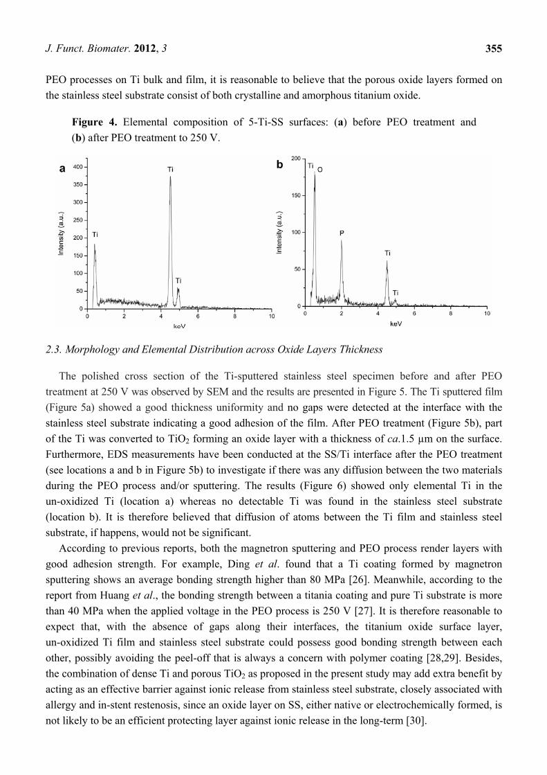
The elemental composition of the Ti film before PEO treatment and of the porous surface after PEO
treatment at 250 V was assessed by energy dispersive X-ray spectrometry (EDS) analyses (Figure 4).
Before the PEO treatment, the surface is exclusively composed of Ti, and no element from the
stainless steel substrate was detected (Figure 4a). In comparison, the oxidized surface (Figure 4b)
showed the presence of O in large amounts (65.04 at%) followed by Ti and P (24.71 at% and
10.25 at%, respectively). The presence of P is due to the incorporation of phosphate from the
electrolyte during the PEO process. No element from the stainless steel substrate was present on the
treated surface. According to previous studies, both crystalline (anatase, rutile) and amorphous
titanium oxide structures are found by conversion of the metallic substrate during PEO of titanium in
sodium phosphate electrolyte [25]. Considering the similarity between voltage-time responses during
J. Funct. Biomater. 2012, 3
355
PEO processes on Ti bulk and film, it is reasonable to believe that the porous oxide layers formed on
the stainless steel substrate consist of both crystalline and amorphous titanium oxide.
Figure 4. Elemental composition of 5-Ti-SS surfaces: (a) before PEO treatment and
(b) after PEO treatment to 250 V.
2.3. Morphology and Elemental Distribution across Oxide Layers Thickness
The polished cross section of the Ti-sputtered stainless steel specimen before and after PEO
treatment at 250 V was observed by SEM and the results are presented in Figure 5. The Ti sputtered film
(Figure 5a) showed a good thickness uniformity and no gaps were detected at the interface with the
stainless steel substrate indicating a good adhesion of the film. After PEO treatment (Figure 5b), part
of the Ti was converted to TiO2 forming an oxide layer with a thickness of ca.1.5 µm on the surface.
Furthermore, EDS measurements have been conducted at the SS/Ti interface after the PEO treatment
(see locations a and b in Figure 5b) to investigate if there was any diffusion between the two materials
during the PEO process and/or sputtering. The results (Figure 6) showed only elemental Ti in the
un-oxidized Ti (location a) whereas no detectable Ti was found in the stainless steel substrate
(location b). It is therefore believed that diffusion of atoms between the Ti film and stainless steel
substrate, if happens, would not be significant.
According to previous reports, both the magnetron sputtering and PEO process render layers with
good adhesion strength. For example, Ding et al. found that a Ti coating formed by magnetron
sputtering shows an average bonding strength higher than 80 MPa [26]. Meanwhile, according to the
report from Huang et al., the bonding strength between a titania coating and pure Ti substrate is more
than 40 MPa when the applied voltage in the PEO process is 250 V [27]. It is therefore reasonable to
expect that, with the absence of gaps along their interfaces, the titanium oxide surface layer,
un-oxidized Ti film and stainless steel substrate could possess good bonding strength between each
other, possibly avoiding the peel-off that is always a concern with polymer coating [28,29]. Besides,
the combination of dense Ti and porous TiO2 as proposed in the present study may add extra benefit by
acting as an effective barrier against ionic release from stainless steel substrate, closely associated with
allergy and in-stent restenosis, since an oxide layer on SS, either native or electrochemically formed, is
not likely to be an efficient protecting layer against ionic release in the long-term [30].

J. Funct. Biomater. 2012, 3
356
Figure 5. Cross-section morphology of 5-Ti-SS samples: (a) before and (b) after PEO
treatment at 250 V, as observed by back-scattered SEM.
resin
Ti film
SS substrate
a
resin
Ti film
SS substrate
TiO2 layer
b
ab
Figure 6. Elemental composition of the cross-section after PEO treatment at 250 V: (a) Ti
film and (b) stainless steel (SS) substrate. The EDS analyses were performed at location a
(for Ti) and b (for SS) indicated in Figure 5b.
2.4. Wettability and Surface Free Energy
Figure 7 includes the results of contact angle measurements and as-calculated surface free energy
(SFE) in water before and after PEO treatment for the 5-Ti-SS samples. The PEO-treated sample at

J. Funct. Biomater. 2012, 3
357
250 V was used as representative. PEO treatment showed a significant influence on the wettability of
the surfaces. Deionized water on the untreated 5-Ti-SS samples formed a regular drop, with a contact
angle of about 102.0°. After PEO treatment, the contact angle decreased to around 38.2°, indicating a
change from hydrophobic to hydrophilic state. The total SFE of the PEO layers was significantly
higher than that of the original Ti film. The marked lowering of contact angle and higher SFE relative
to the untreated surfaces may be determined by the transition from metal to oxide structures and the
increased low scale roughness and porosity [31,32].
Figure 7. Water contact angle and total surface free energy (SFE) of 5-Ti-SS samples
before and after PEO treatment.
0
20
40
60
80
100
120
5-Ti-SS before PEO 5-Ti-SS after PEO
Cont
act a
ngle
in w
ater
(o )
SFE
(mN
/m)
Contact angleSFE
It is well known that platelet activation, which plays a key role in thrombogenicity of blood contacting
materials, depends on surface properties of the material such as surface charge, wettability, surface free
energy, roughness, balance between hydrophobic and hydrophilic groups, and presence of chemical
groups on the surface [33,34]. Song SJ et al. [29] found that the numbers of platelets that adhere on the
surface can be significantly decreased by depositing a TiO2 film on stainless steel, indicating that TiO2
films have much better compatibility. Meanwhile, the research from Wang GX et al. [35] confirmed that
a TiO2-coated NiTi intravascular stent showed increased surface hydrophilicity and enhanced
anticoagulation properties. Further, it has been pointed out that the combination of a TiO2 coating and
specific drugs further enhance the surface blood compatibility and anticoagulation properties [29,36].
It is clear from these results that a porous TiO2 layer with a good adhesion to the substrate can be
produced on the surface of medical stainless steel by combining magnetron sputtering and PEO
process. The properties of the layers such as surface porosity and average pore size can be adjusted by
changing the process parameters. Such a TiO2 porous layer may provide improved drug loading ability
which makes it a good candidate as drug carrier. Once the anti-restenotic drug is released, the TiO2
layer would continue acting as a blood compatible barrier between the stainless steel and blood. To
confirm this hypothesis, follow-up research should focus on evaluation of the drug-release kinetics and
blood compatibility of the layer.

J. Funct. Biomater. 2012, 3
358
4. Conclusions
In this study, a porous oxide layer was formed on the surface of 316L stainless steel by combining
Ti magnetron sputtering and plasma electrolytic oxidation (PEO) process with the aim to produce a
polymer-free drug carrier for drug eluting stent (DES) applications. The morphology of the resultant
layers, their elemental composition as well as the wettability and surface free energy has been
examined. It was found that layer properties, such as surface porosity, pore size and roughness could
be changed by adjusting the duration of the PEO treatment with an optimal condition found after about
23 min (final voltage 250 V). The EDS analyses revealed the presence of O, Ti and P on the oxidized
surfaces, indicating that the layer consisted of TiO2 with P incorporation from the electrolyte. The
cross-sectional morphology revealed defect-free interfaces between the SS substrate, un-oxidized Ti
and TiO2 surface layer. In addition, the wettability and surface free energy of the oxidized samples
were significantly higher than those of the Ti sputtered SS. The findings of this study suggest that a
porous TiO2 layer can be formed on stainless steel by combining sputtering technology and PEO.
Further, the resultant oxide layer has the potential to be used as a drug carrier for DES, thus avoiding
the complications associated with the polymer based carriers.
Acknowledgements
This study is part of the Project P1.02 NEXTREAM under the research program of the BioMedical
Materials Institute, co-funded by the Dutch Ministry of Economic Affairs, Agriculture and Innovation.
The financial contribution of the Nederlandse Hartstichting is gratefully acknowledged.
References
1. Van de Hoeven, B.L.; Pires, N.M.M.; Warda, H.M.; Oemrawsingh, P.V.; Van Vlijmen, B.J.M.;
Quax, P.H.A.; Schalij, M.J. Drug-eluting stents: Results, promises and problems. Int. J. Cardiol.
2005, 99, 9–17.
2. Kukreja, N.; Onuma, Y.; Daemen, J.; Serruys, P.W. The future of drug eluting stents. Pharmacol.
Res. 2008, 57, 171–180.
3. Morice, M.C.; Serruys, P.W.; Sousa, J.E.; Fajadet, J.; Ban Hayashi, E.; Perin, M.; Colombo, A.;
Schuler, G.; Barragan, P.; Guagliumi, G.; Molnar, F.; Falotico, R. A randomized comparison of a
sirolimus-eluting stent with a standard stent for coronary revascularization. N. Engl. J. Med. 2002,
346, 1773–1780.
4. Stone, G.W.; Ellis, S.G.; Cox, D.A.; Hermiller, J.; O’Shaughnessy, C.; Mann, J.T.; Turco, M.;
Caputo, R.; Bergin, P.; Greenberg, J.; Popma, J.J.; Russell, M.E. A polymer based, paclitaxel-
eluting stent in patients with coronary artery disease. N. Engl. J. Med. 2004, 350, 221–231.
5. McFadden, E.P.; Stabile, E.; Regar, E.; Cheneau, E.; Ong, A.T.; Kinnaird, T.; Suddath, W.O.;
Weissman, N.J.; Torguson, R.; Kent, K.M.; Pichard, A.D.; Satler, L.F.; Waksman, R.; Serruys, P.W.
Late thrombosis in drug-eluting coronary stents after discontinuation of antiplatelet therapy.
Lancet 2004, 364, 1519–1521.
6. Wessely, R.; Kastrati, A.; Schömig, A. Late restenosis in patients receiving a polymer-coated
sirolimus-eluting stent subsequently. Ann. Intern. Med. 2005, 143, 392–394.

J. Funct. Biomater. 2012, 3
359
7. Hausleiter, J.; Kastrati, A.; Wessely, R.; Dibra, A.; Mehilli, J.; Schratzenstaller, T.; Graf, I.;
Renke-Gluszko, M.; Behnisch, B.; Dirschinger, J.; Wintermantel, E.; Schömig, A. Prevention of
restenosis by novel drug-eluting stent system with a dose-adjustable, polymer-free, on-site sent
coating. Eur. Heart J. 2005, 26, 1475–1481.
8. Zhang, F.; Zheng, Z.; Chen, Y.; Liu, X.; Chen, A.; Jiang, Z. In vivo investigation of blood
compatibility of titanium oxide films. J. Biomed. Mater. Res. 1998, 42, 128–133.
9. Williams, D.F. Titanium and titanium alloys. In Biocompatibility of Clinical Implant Materials;
CRC Press: Boca Raton, FL, USA, 1981; Volume 1, pp. 9–44.
10. Song, S.; Park, Y.J.; Cho, M.D.; Kim, J.H.; Jeong, M.H.; Kim, Y.S.; Cho, D.L. Preparation of a
drug-eluting stent using a TiO2 film deposited by plasma enhanced chemical vapour deposition as
a drug-combining matrix. J. Mater. Chem. 2010, 20, 4792–4801.
11. Lazarev, V.B.; Sanygin, V.P.; Kvardakov, A.M.; Saakiyan, LS; Efremov, A.P.; Kutsev, A.V. Oxidized
aluminum coatings on steel produced by microarc method. Inorg. Mater. 1991, 27, 614–619.
12. Gu, W.-C.; Lv, G.-H.; Chen, H.; Chen, G.-L.; Feng, W.-R.; Yang S.-Z. PEO protective coatings
on inner surface of tubes. Surf. Coat. Technol. 2007, 201, 6619–6622.
13. Frauchiger, V.M.; Schlottig, F.; Gasser, B.; Textor, M. Anodic plasma-chemical treatment of CP
titanium surfaces for biomedical applications. Biomaterials 2004, 25, 593–606.
14. Yerokhin, A.L.; Nie, X.; Leyland, A.; Matthews, A.; Dowey, S.J. Plasma electrolysis for surface
engineering. Surf. Coat. Technol. 1999, 122, 73–93.
15. Apachitei, I.; Lonyuk, B.; Fratila-Apachitei, L.E.; Zhou, J.; Duszczyk, J. Fatigue response of
porous coated titanium biomedical alloys. Scripta Mater. 2009, 61, 113–116.
16. Necula, B.S.; Apachitei, I.; Tichelaar, F.D.; Fratila-Apachitei, L.E.; Duszczyk, J. An electron
microscopical study on the growth of TiO2-Ag antibacterial coatings on Ti6Al7Nb biomedical
alloy. Acta Biomater. 2011, 7, 2751–2757.
17. Matykina, E.; Berkani, A.; Skeldon, P.; Thompson, G.E. Real-time imaging of coating growth
during plasma electrolytic oxidation of titanium. Electrochim. Acta 2007, 53, 1987–1994.
18. Montero, I.; Fernández, M.; Albella, J.M. Pore formation during the breakdown process in anodic
Ta2O5 fims. Electrochim. Acta 1987, 32, 171–174.
19. Afshar, A.; Vaezi, M.R. Evaluation of electrical breakdown of anodic films on titanium in
phosphate-base solutions. Surf. Coat. Technol. 2004, 186, 398–404.
20. Ryu, H.S.; Mun, S.J.; Lim, T.S.; Kim, H.C.; Shin, K.S.; Hong, S.H. Microstructure evolution
during plasma electrolytic oxidation and its effects on the electrochemical properties of AZ91D
Mg alloy. J. Electrochem. Soc. 2011, 158, C266–C273.
21. Wang, Y.; Lei, T.; Jiang, B.; Guo, L. Growth, microstructure and mechanical properties of
microarc oxidation coatings on titanium alloy in phosphate-containing solution. Appl. Surf. Sci.
2004, 233, 258–267.
22. Rudnev, V.S.; Yarovaya, T.P.; Egorkin, V.S.; Sinebryukov, S.L.; Gnedenkov, S.V. Properties of
coatings formed on titanium by plasma electrolytic oxidation in a phosphate-borate electrolyte.
Russ. J. Appl. Chem. 2010, 83, 664–670.
23. Parfenov, E.V.; Yerokhin, A.L.; Matthews, A. Frequency response studies for the plasma
electrolytic oxidation process. Surf. Coat. Technol. 2007, 201, 8661–8670.

J. Funct. Biomater. 2012, 3
360
24. Sundararajan, G.; Krishna, L.R. Mechanisms underlying the formation of thick alumina coatings
through the MAO coating technology. Surf. Coat. Technol. 2003, 167, 269–277.
25. Matykina, E.; Monfort, F.; Berkani, A.; Skeldon, P.; Thompson, G.E.; Gough, J. Characterization of
sparks-anodized titanium for biomedical applications. J. Electrochem. Soc. 2007, 154, C279–C285.
26. Ding, S.J.; Ju, C.P.; Lin, J.H. Characterization of hydroxyapatite and titanium coatings sputtered
on Ti-6Al-4V substrate. J. Biomed. Mater. Res. 1999, 44, 266–279.
27. Huang, P.; Wang, F.; Xu, K.; Han, Y. Mechanical properties of titania prepared by plasma
electrolytic oxidation at different voltages. Surf. Coat. Technol. 2007, 201, 5168–5171.
28. Otsuka, Y.; Chronos, N.A.; Apkarian, R.P.; Robinson, K.A. Scanning electron microscopic
analysis of defects in polymer coatings of three commercially available stents: Comparison of
BiodivYsio, Taxus and Cypher stents. J. Invasive Cardiol. 2007, 19, 71–76.
29. Song, S.J.; Kim, K.S.; Kim, K.H.; Li, H.J.; Kim, J.H.; Jeong, M.H.; Kim, B.H.; Ko, Y.M.; Cho, D.L.
Preparation of a biocompatible stent surface by plasma polymerization followed by chemical
grafting of drug compounds. J. Mater. Chem. 2009, 19, 3248–3252.
30. Díaz, M.; Sevilla, P.; Galán, A.M.; Escolar, G.; Engel, E.; Gil, F.J. Evaluation of ion release,
cytotoxicity, and platelet adhesion of electrochemical anodized 316L stainless steel cardiovascular
stents. J. Biomed. Mater. Res. Part B 2008, 87B, 555–561.
31. Annarelli, C.C.; Fornazero, J.; Cohen, R.; Bert, J.; Besse, J.L. Collidal protein solutions as a new
standard sensor for adhesive wettability measurements. J. Colloid Interface Sci. 1999, 213, 386–394.
32. Chrzanowski, W.; Neel, E.A.A.; Armitage, D.A.; Knowles, J.C. Effect of surface treatment on the
bioactivity of nickel-titanium. Acta Biomater. 2008, 4, 1969–1984.
33. Brier-Russell, D.; Salzman, E.W.; Lindon, J.; Merrill, E.W.; Dincer, A.K.; Wu, J.S. In vitro
assessment of interaction of blood with model surfaces: Acrylates and methacrylates. J. Colloid
Interface Sci. 1981, 81, 311–318.
34. Haynes, C.A.; Norde, W. Globular proteins at solid/liquid interface. Colloid Surface B 1994, 2,
517–566.
35. Wang, G.X.; Shen, Y.; Zhang, H.; Quan, X.J.; Yu, Q.S. Influence of surface microroughness by
plasma deposition and chemical erosion followed by TiO2 coating upon anticoagulation,
hydrophilicity, and corrosion resistance of NiTi alloy stent. J. Biomed. Mater. Res. 2008, 85A,
1096–1102.
36. Yang, Z.; Wang, J.; Luo, R.; Li, X.; Chen, S.; Sun, H.; Huang, N. Improved hemocompatibility
guided by pulsed plasma tailoring the surface amino functionalities of TiO2 coating for covalent
immobilization of heparin. Plasma Process. Polym. 2011, 8, 850–858.
© 2012 by the authors; licensee MDPI, Basel, Switzerland. This article is an open access article
distributed under the terms and conditions of the Creative Commons Attribution license
(http://creativecommons.org/licenses/by/3.0/).