characterization of cementitiously stabilized layers...
TRANSCRIPT

NCHRP Project 04-36
CHARACTERIZATION OF CEMENTITIOUSLY STABILIZED LAYERS FOR USE IN PAVEMENT
DESIGN AND ANALYSIS
FINAL REPORT APPENDIXES
Prepared for National Cooperative Highway Research Program
Transportation Research Board of
The National Academies
Haifang Wen Balasingam Muhunthan,
Washington State University Pullman, WA
Tuncer Edil
James M. Tinjum, University of Wisconsin at Madison
Madison, WI

Characterization of Cementitiously Stabilized Layers NCHRP Project 4-36 for Use in Pavement Design and Analysis
Appendix A. Literature Review and Survey Results
A-1

Characterization of Cementitiously Stabilized Layers NCHRP Project 4-36 for Use in Pavement Design and Analysis
CONTENTS LIST OF FIGURES ................................................................................................................................ A-5
LIST OF TABLES .................................................................................................................................. A-7
CHAPTER A-1. PERFORMANCE ISSUES OF PAVEMENT WITH CEMENTITIOUSLY STABILIZED LAYERS (CSL) ............................................................................................................. A-8
Hot Mix Asphalt Pavement ................................................................................................................ A-8
Block Cracking in HMA .................................................................................................................... A-8
Transverse Cracking Induced by Shrinkage of CSL ......................................................................... A-8
Longitudinal Cracking .................................................................................................................... A-10
Bottom-Up Cracking (Alligator Cracking) of HMA Layer ............................................................. A-13
Rutting ............................................................................................................................................. A-15
Heave .............................................................................................................................................. A-17
Concrete Pavement ........................................................................................................................... A-18
CHAPTER A-2. PROPERTIES OF CEMENTITIOUSLY STABILIZED MATERIALS LINKED TO PAVEMENT PERFORMANCE .................................................................................................. A-20
Shrinkage of CSL and Related Pavement Distresses ..................................................................... A-20
Moisture .......................................................................................................................................... A-20
Binder Content ................................................................................................................................ A-21
Soil Properties ................................................................................................................................ A-21
Thermal Cooling ............................................................................................................................. A-22
Fatigue of CSL and Related Pavement Distresses ......................................................................... A-22
Bottom-Up Tensile-Fatigue of CSL ................................................................................................. A-22
Crushing Fatigue of CSL ................................................................................................................ A-24
Durability of CSL and Related Pavement Performance ............................................................... A-25
Swelling/Shrinkage of CSL and Related Pavement Performance ................................................ A-26
Expansive Soils ............................................................................................................................... A-26
Sulfate-Bearing Soils ...................................................................................................................... A-27
Strength of Cementitiously Stabilized Materials and Related Pavement Performance ............. A-28
Stiffness of CSL and Related Pavement Performance ................................................................... A-29
Erodibility .......................................................................................................................................... A-29
Interface Bond ................................................................................................................................... A-29
A-2
Characterization of Cementitiously Stabilized Layers NCHRP Project 4-36 for Use in Pavement Design and Analysis
CHAPTER A-3. LITERATURE REVIEW FOR PROPERTIES OF CSL ..................................... A-31
Strength and Modulus ...................................................................................................................... A-31
Durability ........................................................................................................................................... A-36
Wetting and Drying ......................................................................................................................... A-36
Freezing and Thawing .................................................................................................................... A-36
Moisture Susceptibility .................................................................................................................... A-37
Erodibility ....................................................................................................................................... A-38
Fatigue ................................................................................................................................................ A-40
Shrinkage ........................................................................................................................................... A-41
CHAPTER A-4. TEST PROCEDURES FOR CSM PROPERTIES ............................................... A-43
Strength Tests .................................................................................................................................... A-43
Unconfined Compressive Test ......................................................................................................... A-43
IDT Strength Test ............................................................................................................................ A-44
Modulus of Rupture Test ................................................................................................................. A-46
Direct Tensile Strength Test ............................................................................................................ A-47
Modulus Tests.................................................................................................................................... A-48
Resilient Modulus Test .................................................................................................................... A-48
Modulus of Elasticity Test ............................................................................................................... A-49
Flexural Stiffness Test ..................................................................................................................... A-50
IDT Modulus Test ........................................................................................................................... A-50
Seismic Modulus Test ...................................................................................................................... A-51
Ultrasonic Pulse Velocity Test ........................................................................................................ A-52
Durability Tests ................................................................................................................................. A-54
Wetting and Drying Test ................................................................................................................. A-54
Freezing and Thawing Test ............................................................................................................. A-54
Moisture Susceptibility Test ............................................................................................................ A-55
Erodibility Tests .............................................................................................................................. A-56
Fatigue Tests ...................................................................................................................................... A-60
Flexural Fatigue Test ...................................................................................................................... A-60
Large-Scale Model Experiment ...................................................................................................... A-61
Shrinkage Tests ................................................................................................................................. A-61
A-3

Characterization of Cementitiously Stabilized Layers NCHRP Project 4-36 for Use in Pavement Design and Analysis
REFERENCES ...................................................................................................................................... A-65
FINDINGS OF SURVEY AND REVIEW OF SPECIFICATIONS ................................................ A-75
A-4

Characterization of Cementitiously Stabilized Layers NCHRP Project 4-36 for Use in Pavement Design and Analysis
LIST OF FIGURES Figure A-1. Block Cracking in HMA with Stabilized Base (Scullion 2002) ............................. A-8 Figure A-2. Transverse Cracking due to Shrinkage Cracking of CSL (Freeman and Little 2002)
................................................................................................................................ A-9 Figure A-3. Top-Down Cracking in HMA with CSL as Base (Wen and Ramme 2008) ......... A-10 Figure A-4. Top-Down Cracking in HMA Layer on Stabilized Base (Wen and Ramme 2008) .. A-
10 Figure A-5. Top-Down Cracking Based on Accelerated Pavement Testing (Meng et al. 2004) . A-
11 Figure A-6. Dry-Land Cracking (Scullion et al. 2003) ............................................................. A-12 Figure A-7. Dry-Land Cracking Initiated in Subgrade (Luo and Prozzi 2008) ........................ A-12 Figure A-8. Surface Raveling of Stabilized Materials (Thogersen 2005) ................................ A-13 Figure A-9. Alligator Cracking in Asphalt Pavement with CSL (Yeo 2008) ........................... A-14 Figure A-10. Ladder-Type Fatigue Failure (Scullion et al. 2003) ............................................ A-14 Figure A-11. Cracking of Asphalt Pavement with CSL (Li et al. 1999) .................................. A-15 Figure A-12. Rutting in Asphalt Layer (Yeo 2008) .................................................................. A-16 Figure A-13. Crushing Fatigue of CSL (De Beer 1990) ........................................................... A-17 Figure A-14. Heave in Asphalt Pavement (Si 2008) ................................................................ A-18 Figure A-15. Cracking of Concrete Pavement .......................................................................... A-18 Figure A-16. Shrinkage Cracking of CSL (George 2001) ........................................................ A-20 Figure A-17. Fatigue Cracking in CSL (Yeo et al. 2002) ......................................................... A-23 Figure A-18. Fatigue Cracking in CSL Trenching (Moisture in Cracks) (Yeo 2008) .............. A-23 Figure A-19. Three Phases of CSL Fatigue (Theyse 1996) ...................................................... A-24 Figure A-20. Compressive Crushing Fatigue of CSL (De Beer 1990) ..................................... A-25 Figure A-21. Material Degradation after Freeze-Thaw Cycles (Khoury 2005) ....................... A-26 Figure A-22. Swell of Sulfate-Bearing Soil Stabilized with Calcium-Based Additive (Texas DOT
2005) .................................................................................................................... A-27 Figure A-23. Sulfate-Bearing Soil (Texas DOT 2005) ............................................................. A-28 Figure A-24. Effect of Density on Flexural Modulus (Carteret et al. 2009) ............................ A-31 Figure A-25. Relationship between UCS and IDT Strength (Kennedy and Hudson 1973) ..... A-33 Figure A-26. Relationship between Flexural Strength (MOR) and Resilient Modulus (Sobhan
and Krizek 1998).................................................................................................. A-33 Figure A-27. Correlation between Seismic Modulus and Resilient Modulus (Hilbrich and
Scullion 2007) ...................................................................................................... A-34 Figure A-28. Relationship between Equivalent Cracked Modulus of CSL and Original UCS of
CSM (Department of the Army and the Air Force 1994) .................................... A-35 Figure A-29. Effects of Freeze-Thaw Cycles on the MOR (Khoury 2005) ............................. A-37 Figure A-30. Relationship between DVs obtained from Tube Suction Test Results and Weight
Loss from Wet-Dry/Freeze-Thaw Test Results (Syed et al. 2002) ...................... A-38
A-5

Characterization of Cementitiously Stabilized Layers NCHRP Project 4-36 for Use in Pavement Design and Analysis
Figure A-31. Relationship between Hydraulic Shear Stress and Erosion Rate (Indraratna 2008) A-40
Figure A-32. Relationship between Fatigue Life and Initial Strain (Carteret 2009) ................ A-41 Figure A-33. Unconfined Compressive Strength Test Setup.................................................... A-44 Figure A-34. IDT Test Setup (Yeo 2008) ................................................................................. A-46 Figure A-35. MOR Test Setup (Yeo 2008) .............................................................................. A-47 Figure A-36. Modified Tensile Strength Test (Chakrabarti and Kodikara 2007) ..................... A-48 Figure A-37. Resilient Modulus Test Setup (AASHTO T307) ................................................ A-49 Figure A-38. Modulus of Elasticity Test Setup (ASTM C469) ................................................ A-50 Figure A-39. Seismic Modulus Test Setup (Guthrie et al. 2001) ............................................. A-52 Figure A-40. Schematic of Pulse Velocity Test Apparatus (ASTM C597) .............................. A-53 Figure A-41. Tube Suction Test Setup (Guthrie et al. 2001) .................................................... A-56 Figure A-42. South Africa Wheel Tracking Test ...................................................................... A-58 Figure A-43. Rotational Shear Device (Van Wijk 1985) ......................................................... A-58 Figure A-44. Jetting Test (Van Wijk 1985) .............................................................................. A-59 Figure A-45. Evaluation of Various Erosion Tests (Van Wijk 1985) ...................................... A-59 Figure A-46. Flow of Water during Loading and Unloading Phases ....................................... A-60 Figure A-47. LSME Setup ........................................................................................................ A-61 Figure A-48. Free Drying Shrinkage Test ................................................................................ A-62 Figure A-49. Restrained Slab at Base and Ends (Weiss et al. 1998) ........................................ A-63 Figure A-50. Test Setup of Coefficient of Thermal Expansion (Naik et al. 2006) ................... A-64
A-6

Characterization of Cementitiously Stabilized Layers NCHRP Project 4-36 for Use in Pavement Design and Analysis
LIST OF TABLES Table A-1. Matrix of the Relationship between Pavement Performance and Engineering
Parameters ............................................................................................................... A-30 Table A-2. Durability Criteria for CSM (Corp of Engineers 1994) ......................................... A-37 Table A-3. Comparison of Resilient Modulus and Seismic Modulus Test Methods and
Equipment (Hilbrich and Scullion 2007) ................................................................ A-52
A-7

Characterization of Cementitiously Stabilized Layers NCHRP Project 4-36 for Use in Pavement Design and Analysis
CHAPTER A-1. PERFORMANCE ISSUES OF PAVEMENT WITH CEMENTITIOUSLY STABILIZED LAYERS (CSL) Hot Mix Asphalt Pavement
The performance of hot mix asphalt (HMA) pavement is significantly affected by
cementitiously stabilized layers (CSL), especially when CSL are located directly underneath HMA layers. Stabilized subbase and base layers can reduce the rutting of HMA pavement as a result of minimal rutting in the subgrade, subbase, and base (Von Quintus et al. 2005). The bottom-up fatigue cracking of HMA also can be reduced. However, there are performance issues related to CSL, mostly when they are used as the base course.
Block Cracking in HMA
Block cracking often is reported in the HMA surface when the pavement has a stabilized
base. Block cracking is caused by shrinkage of the underlying stabilized base and often occurs when the HMA layer is thin, as for local roads (Figure A-1). Highways in many parts of the world that use stiff bases and thin HMA layers also have encountered this problem (Yue 2004, Zube 1969). The shrinkage, caused by a loss of moisture and temperature variation, typically initiates shortly after construction and continues thereafter. According to Zube (1969), high unconfined compressive strength (UCS) causes block cracking which is likely due to the high shrinkage of CSL with high cement content and high strength. In short, block cracking can be attributed to the shrinkage of CSL.
Figure A-1. Block Cracking in HMA with Stabilized Base (Scullion 2002)
Transverse Cracking Induced by Shrinkage of CSL
Transverse cracking in the surface layer that results from shrinkage of the stabilized base,
as shown in Figure A-2, starts from the bottom of the surface layer and propagates through the surface layer. The cracking is due to the bond between the surface layer and stabilized base (George 2002). Transverse cracking is also a concern for pavements with a stabilized subbase
A-8

Characterization of Cementitiously Stabilized Layers NCHRP Project 4-36 for Use in Pavement Design and Analysis
and granular base, but at a much later stage (Ramsey 1959). The shrinkage cracking of the subbase causes stress concentrations at the locations of the cracks and eventually affects the stress distribution in the surface layer.
Figure A-2. Transverse Cracking due to Shrinkage Cracking of CSL (Freeman and Little
2002) Atkinson (1990) reports that shrinkage cracking in CSL causes transverse cracking in
HMA and is prominent in thin HMA pavement. Chen (2007) reports that lack of mellowing for lime slurry stabilized base layers causes shrinkage cracking and then transverse cracking in the HMA surface. Little et al. (1995) found that a high modulus value causes wide shrinkage cracks and low load transfers across the crack.
George (2002) found that high-strength CSL are prone to shrinkage cracking, based on Long-Term Pavement Performance (LTPP) and other pavements. When the 7-day in-service strength is 300 psi or lower, no shrinkage cracking occurs. Increasing the fines content increases the cracking intensity. Bituminous curing of the CSL before the placement of the surface layers corresponds to 65% relative humidity (RH) for most specifications. In the laboratory, moist curing corresponds to 95% RH. Crack width is significantly affected by drying shrinkage. Crack spacing decreases with an increase in friction between the CSL and underlying layer. For wide shrinkage cracks, load transfer efficiency is between 35% and 55%, and 80% for fine cracks for coarse-grained aggregate. Cracks wider than 0.1 inch (measured on HMA surface) affect the pavement performance significantly. For fine-grained soil, the critical crack width is claimed to be 0.06 inch. Decreasing the strength of the CSL decreases the tensile stress in the CSL. There is an optimum shrinkage strain level: 525 microstrain for fine-grained soil and 310 microstrain for coarse-grained soils, respectively.
Therefore, as with block cracking, the shrinkage of CSL causes transverse cracking of asphalt pavement and thus is included in this study.
A-9

Characterization of Cementitiously Stabilized Layers NCHRP Project 4-36 for Use in Pavement Design and Analysis
Longitudinal Cracking (a) Longitudinal cracking in wheel path (top-down cracking) CSL provide strong support for surface layer, which is beneficial in reducing the fatigue
of surface layers that can occur as a result of tension at the bottom of the surface layer. Therefore, alligator cracking in HMA can be mitigated when a stabilized base is used, unless the pavement is under-designed or the CSL are fatigued. However, for asphalt pavements that use high-stiffness CSL as the base, the HMA surface layer is prone to top-down fatigue cracking (ARA 2004), as shown in Figures A-3, A-4, and A-5. This top-down fatigue cracking has been confirmed by other researchers (Meng et al. 2004 and Barstis et al. 2000); and the team’s field projects that use stabilized base layers also exhibited this distress. Actually, transverse and longitudinal cracks in the wheel path are the two most major distresses for highway pavements constructed with CSL, as reported by George (2002).
Figure A-3. Top-Down Cracking in HMA with CSL as Base (Wen and Ramme 2008)
Figure A-4. Top-Down Cracking in HMA Layer on Stabilized Base (Wen and Ramme
2008)
A-10

Characterization of Cementitiously Stabilized Layers NCHRP Project 4-36 for Use in Pavement Design and Analysis
Figure A-5. Top-Down Cracking Based on Accelerated Pavement Testing (Meng et al.
2004) Syed and Scullion (2001) report that a stabilized base with high stiffness causes
longitudinal cracking in the wheel path. The high stiffness of CSL is due to an excessive amount of stabilizer. As a result, the authors recommend that a 7-day UCS of 200 psi should be targeted.
In another study, Scullion et al. (2003) also found that a high modulus value of cement-stabilized full-depth recycled base leads to more longitudinal cracking in the wheel path.
The literature supports that high stiffness or modulus values of CSL lead to top-down cracking in asphalt pavement. Stiffness and modulus values also are needed for the response model of a pavement structure to determine stress and strain.
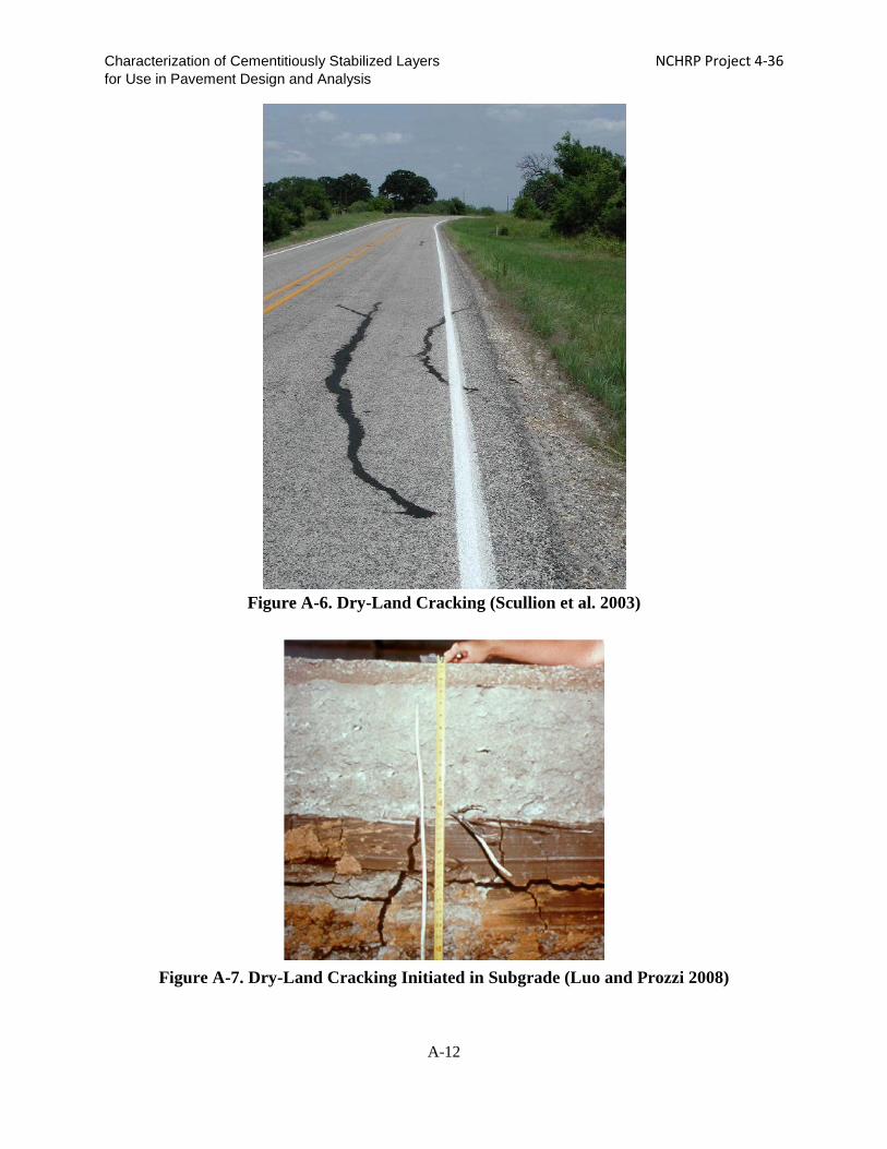
(b) Longitudinal cracking (outside wheel path): dry-land cracking Dry-land cracking occurs as a result of shrinkage of expansive soils. The shrinkage
cracks reflect through the upper layers and appear in the HMA surface, as shown in Figure A-6. Luo and Prozzi (2008) report that longitudinal dry-land cracking initiates in untreated expansive soil and appears in the HMA surface, as shown in Figure A-7. Adding lime reduces the plasticity index (PI) value, suction, compression index value, and the swelling potential of expansive soils. Wise and Hudson (1971) also report that the subgrade beneath the pavement at the centerline has a high moisture content whereas the moisture content underneath the shoulder fluctuates. The shrink and swell caused by moisture change can lead to longitudinal dry-land cracking. Syed and Scullion (2001) indicate that the shrink-swell of subgrade comprised of expansive soil results in dry-land cracking. The shrinkage cracking in the subgrade reflects through the CSL and appears at the HMA surface. This phenomenon also is confirmed by forensic studies by Chen (2007) and Atkinson (1990) in which expansive soil causes dry-land cracking.
A-11
Characterization of Cementitiously Stabilized Layers NCHRP Project 4-36 for Use in Pavement Design and Analysis
Figure A-6. Dry-Land Cracking (Scullion et al. 2003)
Figure A-7. Dry-Land Cracking Initiated in Subgrade (Luo and Prozzi 2008)
A-12

Characterization of Cementitiously Stabilized Layers NCHRP Project 4-36 for Use in Pavement Design and Analysis
Bottom-Up Cracking (Alligator Cracking) of HMA Layer Bottom-up cracking may be due to CSL surface raveling or fatigue of the CSL, as
follows: (a) Bottom-up cracking due to CSL surface raveling Based on accelerated pavement testing, studies (Li et al. 1999, Meng et al. 2004,
Thogersen 2005) show that the surface of a stabilized base layer can ravel, creating a layer of loose material between the HMA and base CSL (Figure A-8). Raveling of the base increases the strain level at the bottom of the HMA, which can result in alligator cracking. In addition, pumping was observed in these cases. The pumping is caused by the loss of fines in the loose material layer. This phenomenon may be linked to the erodibility of stabilized materials, which often happens when relatively fine raw materials are treated (De Beer 1985).
Li et al. (1999) reported the loose layer is about 0.8 in. thick and is believed to be due to shear failure within the CSL as a result of horizontal loading, which in turn causes alligator cracking.
Figure A-8. Surface Raveling of Stabilized Materials (Thogersen 2005)
(b) Fatigue of stabilized base (bottom-up tension) The fatigue of a pavement is a form of structural failure. According to studies conducted
in South Africa (De Beer 1990), there are two types of fatigue failure for CSL, bottom tension fatigue and top compression (top crushing).
Alligator cracking in thin HMA pavement, as shown in Figure A-9, also can be accelerated by fatigue cracking of the stabilized base or subbase caused by repeated traffic loads (Pretorius et al. 1972, Li et al. 1999). The fatigue resistance of CSL is reduced when subjected to freeze-thaw and/or wet-dry cycling (Naji and Zaman 2005). Bottom-up cracking in HMA could be due to bottom-up fatigue cracking of the CSL. Under repeated traffic loads, microcracking is initiated at the bottom of CSL due to tensile stress/strain, and propagates upwards.
A-13

Characterization of Cementitiously Stabilized Layers NCHRP Project 4-36 for Use in Pavement Design and Analysis
Figure A-9. Alligator Cracking in Asphalt Pavement with CSL (Yeo 2008)
De Beer (1985) also indicates that when there are two or more lifts of CSL, the upper lift
tends to crack first due to debonding and becomes more fractured than the bottom lift. Dry CSL densify whereas the wet, upper CSL loosen. A loose interlayer between the asphalt and CSL increases the potential for fatigue. Cement slurry, cement powder, or bitumen membrane are recommended for use between two lifts. Atkinson (1990) also found that debonding between lifts of CSL causes high stress levels at the bottom of the top layers and thus induces fatigue cracking.
Pretorius et al. (1972) report that after the formation of transverse shrinkage cracking, longitudinal fatigue cracking starts first in the wheel path, which results in corner loading and consequently ladder-type fatigue cracking, as shown in Figure A-10. Norling (1963) notes that ladder-type cracking indicates inadequate design.
Figure A-10. Ladder-Type Fatigue Failure (Scullion et al. 2003)
A-14
Characterization of Cementitiously Stabilized Layers NCHRP Project 4-36 for Use in Pavement Design and Analysis
Jameson et al. (1992) found that with an increase in the number of load cycles, the
modulus value decreases linearly on log(E) versus log(Cycles) plots. The modulus value reduces to one-tenth of its initial value when the first crack is visible in the asphalt layer. For asphalt layers that are less than 4-inch thick, the fatigue of the CSL is based on 50% of the initial modulus value of the CSL or 10% cracking in trafficked areas. For an asphalt layer that is thicker than 4 inches, the fatigue life of the CSL is defined as the number of cycles to 50% of the initial modulus value of the CSL.
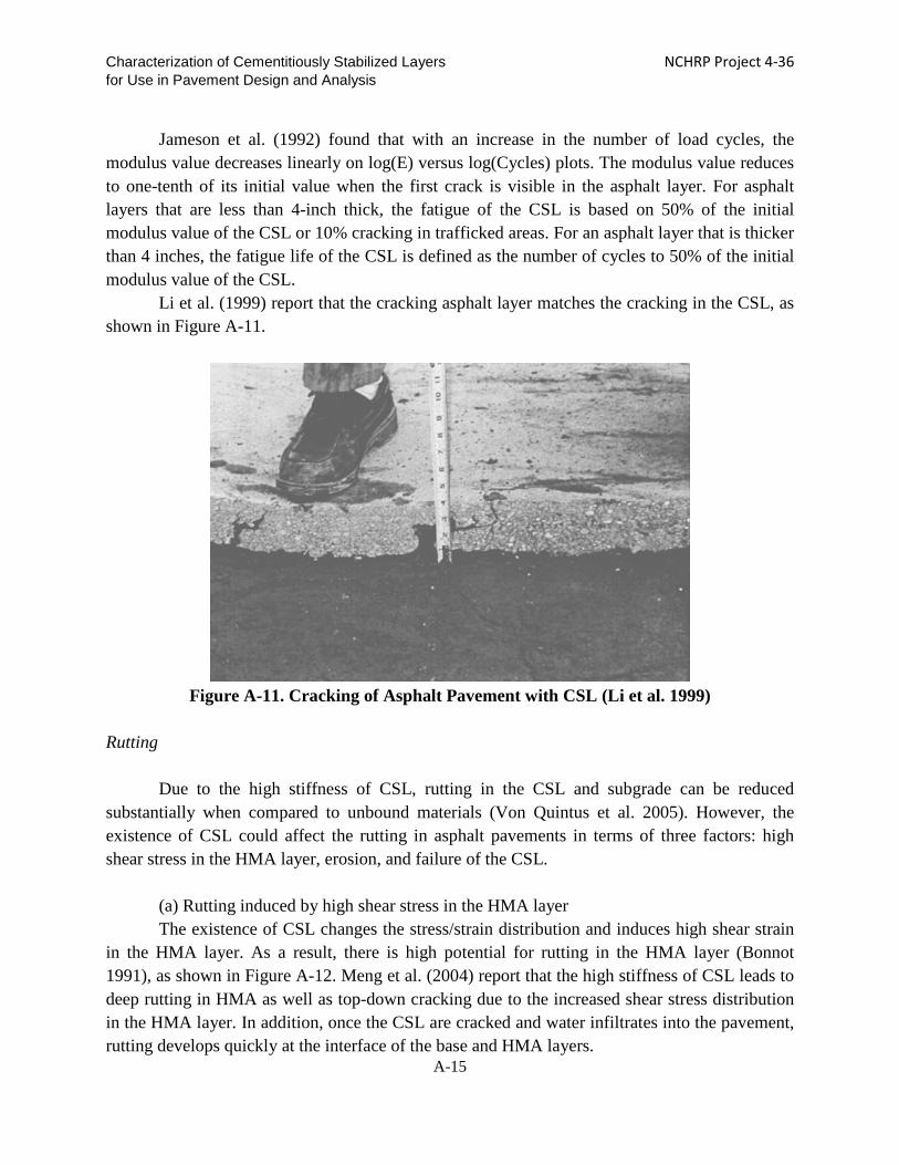
Li et al. (1999) report that the cracking asphalt layer matches the cracking in the CSL, as shown in Figure A-11.
Figure A-11. Cracking of Asphalt Pavement with CSL (Li et al. 1999)
Rutting
Due to the high stiffness of CSL, rutting in the CSL and subgrade can be reduced
substantially when compared to unbound materials (Von Quintus et al. 2005). However, the existence of CSL could affect the rutting in asphalt pavements in terms of three factors: high shear stress in the HMA layer, erosion, and failure of the CSL.
(a) Rutting induced by high shear stress in the HMA layer The existence of CSL changes the stress/strain distribution and induces high shear strain
in the HMA layer. As a result, there is high potential for rutting in the HMA layer (Bonnot 1991), as shown in Figure A-12. Meng et al. (2004) report that the high stiffness of CSL leads to deep rutting in HMA as well as top-down cracking due to the increased shear stress distribution in the HMA layer. In addition, once the CSL are cracked and water infiltrates into the pavement, rutting develops quickly at the interface of the base and HMA layers.
A-15

Characterization of Cementitiously Stabilized Layers NCHRP Project 4-36 for Use in Pavement Design and Analysis
Figure A-12. Rutting in Asphalt Layer (Yeo 2008)
(b) Rutting induced by erosion of CSL Rutting can occur when there is a loose layer between the HMA and CSL, which results
from erosion and pumping of fines in the CSL. De Beer (1985) found that when lime is used to treat sand that is used as a base material, raveling, instead of fracturing, occurs, which causes rutting or increased tensile strain at the bottom of the HMA layer for alligator cracking.
Metcalf et al. (2001) found debonding between the asphalt and CSL, with free water and a soft layer at the interface. The erosion of CSL causes rutting. CSL that are thick and have low cement content perform best in terms of rutting and cracking. Li et al. (1992) also report that when CSL are dry, minimal rutting occurs. However, after CSL are cracked, the entrance of water causes rutting quickly.
(c) Rutting due to fatigue failure in CSL Top compression/crushing results from fatigue that is due to repeated compression at the
top of the CSL. For thick CSL, the tensile strain at the bottom is very small so that tensile fatigue is not an issue. According to De Beer (1990), thick CSL fail in compression (crushing) in the top 2 - 3 inches, as shown in Figure A-13. As a result, rutting occurs in the crushed materials. Increasing the UCS reduces the compression strain and thus increases the compression fatigue life. A compressive strain of 1% is stated to be the failure strain for compression fatigue. The compressive strain increases as the load repetitions increase.
Theyse et al. (1996) report that increasing the UCS increases the compression fatigue life. With regard to compression fatigue characterization, a 0.08-inch rut is criterion used for crushing initiation and a 0.4-inch rut is used for advanced rutting (Theyse et al. 1995). Jameson et al. (1992) also report that for thick CSL (>12 in.), crushing occurs in the top 2 inches of the CSL. Crushing does not cause cracking in the surface layer. However, Theyse et al. observed permanent deformation. The lower the cement content, the finer is the crushed CSL.
A-16

Characterization of Cementitiously Stabilized Layers NCHRP Project 4-36 for Use in Pavement Design and Analysis
Figure A-13. Crushing Fatigue of CSL (De Beer 1990)
Heave
Expansive soils often are stabilized to mitigate swelling. However, heaving could still
occur when sulfate-bearing soil is stabilized with calcium-based stabilizer in the presence of moisture. Chen et al. (2005) report that the formation of ettringite in lime-treated sulfate-bearing soil causes heaving in the pavement surface. Si (2008) reports that the swell of fly ash-stabilized sulfate-bearing soil causes heave in HMA, as shown in Figure A-14. Lime and fly ash are effective in reducing the swell of sulfate-bearing soils.
A-17

Characterization of Cementitiously Stabilized Layers NCHRP Project 4-36 for Use in Pavement Design and Analysis
Figure A-14. Heave in Asphalt Pavement (Si 2008)
Concrete Pavement
For concrete pavement with stabilized base layers, most of the reports indicate positive
effects, such as reduced faulting, pumping, and cracking (Neal and Woodstrom 1977, ARA 2004, Selezneva et al. 2000, Ruiz et al. 2005, Hall and Crovetti 2007). Nussbaum and Childs (1975) report that using CSL greatly increases the load-carrying capacity of concrete slabs. However, a study by Mallela et al. (2007) shows that the bond between the concrete layer and stabilized base might contribute to early-stage cracking in concrete pavement. The use of a bond breaker is recommended in such cases (Mallela et al. 2007, Ruiz et al. 2005). The erosion of CSL, especially weakly stabilized materials, also may cause pumping and resultant faulting and cracking, as shown in Figure A-15 (ARA 2004, Jung et al. 2009).
Figure A-15. Cracking of Concrete Pavement
A-18

Characterization of Cementitiously Stabilized Layers NCHRP Project 4-36 for Use in Pavement Design and Analysis
In summary, performance issues related to asphalt pavements with CSL include block
cracking, transverse cracking, top-down and bottom-up fatigue cracking, rutting, and heaving. For concrete pavements with CSL, the distresses related to CSL include pumping, faulting and cracking.
The properties of CSL that are related to performance issues include stiffness, strength, fatigue, erodibility, swelling, durability, and shrinkage. These properties should be included in the pavement design and analysis.
A-19

Characterization of Cementitiously Stabilized Layers NCHRP Project 4-36 for Use in Pavement Design and Analysis
CHAPTER A-2. PROPERTIES OF CEMENTITIOUSLY STABILIZED MATERIALS LINKED TO PAVEMENT PERFORMANCE
Based on the previous discussion outlined in Chapter 1, the properties of CSL that are
related to pavement performance are identified and described in detail in the following sections.
Shrinkage of CSL and Related Pavement Distresses
Shrinkage cracking of CSL as base layers, as shown in Figure A-16, can cause the cracking of the surface layer due to the bond between the surface layer and the CSL. Shrinkage of CSL includes autogenous shrinkage due to hydration, drying shrinkage due to loss of moisture and thermal shrinkage due to low temperature contraction (ACI 2008). Shrinkage of CSL, when restrained (e.g., bonding from underlying layer), causes the development of tensile stress in the CSL. When the tensile stress exceeds the tensile strength of the stabilized materials, shrinkage cracking occurs (George 1990). Shrinkage cracking could occur within a few days or over a couple of years, depending on the curing, shrinkage strain, and other factors. Shrinkage of CSL is affected by many factors, such as moisture, additive content, raw material characteristics, and curing after compaction.
Figure A-16. Shrinkage Cracking of CSL (George 2001)
Moisture
Kodikara and Chakrabarti (2001) report that shrinkage results from moisture loss, which
leads to matric suction (capillary forces), osmotic suction, and thermal cooling. George (1990, 2001) reports that moisture content that is higher than the optimum moisture content (OMC) causes excessive shrinkage cracking. George (1990) also reports that shrinkage can be reduced by reducing molding moisture, increasing compaction density, avoiding montorillonite clay, and limiting the degree of saturation to 70 percent.
A-20

Characterization of Cementitiously Stabilized Layers NCHRP Project 4-36 for Use in Pavement Design and Analysis
The moisture content in CSL is affected by the curing method. Sebesta (2005) reports that bituminous curing is minimally effective in reducing cracking problems. Bituminous curing and dry curing provide little difference in shrinkage cracking for 4% cement sections. Shrinkage cracking occurs within the first two days. However, moist curing works better in mitigating shrinkage cracking than dry curing and prime curing for 8% cement sections.
Pretorius et al. (1971) use the theory of viscoelasticity to analyze shrinkage cracking. Increasing the RH reduces the creep and shrinkage strain but increases the relaxation modulus. With an increase in curing time, the tensile strength continues to increase at 100% RH during curing. However, for other RH values, the strength value reaches a peak and then starts to decrease. Increasing the RH reduces shrinkage stress.
Binder Content
Sebesta (2005) reports that increasing the cement content increases the amount of
shrinkage cracking. Matthew et al. found that low strength ensures narrow and closely spaced shrinkage cracks that do not reflect through the wearing course. This finding is in line with that of Van Blerk and Scullion (1995) who conclude that high-strength CSL have wide cracks at large spacing and low strength CSL have fine cracks at close spacing.
Little et al. (1995) report that shrinkage cracking spacing depends on tensile strength and the friction between the CSL and underlying layer. The width of the cracks depends on the tensile stiffness of the CSL. A maximum shrinkage strain of 250 microstrain is recommended.
Soil Properties
The characteristics of soils directly affect the shrinkage behavior of CSL. Norling (1973)
found that increasing the clay content increases the occurrence of shrinkage. Van Blerk and Scullion (1995) also indicate that an increase in the plasticity index (PI) value increases the shrinkage potential. Smectite clay causes the most shrinkage, when compared to other types of clay. The linear shrinkage of the fine fraction of the aggregate is a good indicator of the ultimate drying shrinkage of the CSL. It is recommended that linear shrinkage of 1.5%, PI value of 4.0, passing #200 sieve of 7%, and shrinkage after 21 days of 250 microstrain are the maximum allowed.
Kodikara and Chakrabarti (2001) report that a clay size that is smaller than 0.08 mil is responsible for shrinking and swelling. Autogenous shrinkage accounts for only 5% of the total shrinkage. The shrinkage potential of cementiously stabilized materials (CSM) is between that of clay and cement paste. Adding cement to clay reduces shrinkage due to the reduction in matric suction. However, after reaching a low point, adding more cement will induce higher shrinkage strain due to more gel particles. The restrained shrinkage cracks were examined with a microscope in the Kodikara and Chakrabarti study.
A-21

Characterization of Cementitiously Stabilized Layers NCHRP Project 4-36 for Use in Pavement Design and Analysis
Thermal Cooling
Bonnot (1991) reports that factors that affect shrinkage include water content, thermal shrinkage, and the strength of the materials. Shrinkage cracking can result from thermal contraction. Cooling by 9⁰F to 18⁰F can cause thermal cracking in the laboratory.
Fatigue of CSL and Related Pavement Distresses
There are two types of fatigue failure for CSL: bottom-up tensile-fatigue and top-down
compressive-fatigue.
Bottom-Up Tensile-Fatigue of CSL Bottom-up tensile-fatigue of CSL, as shown in Figure A-17, occurs as a result of tensile
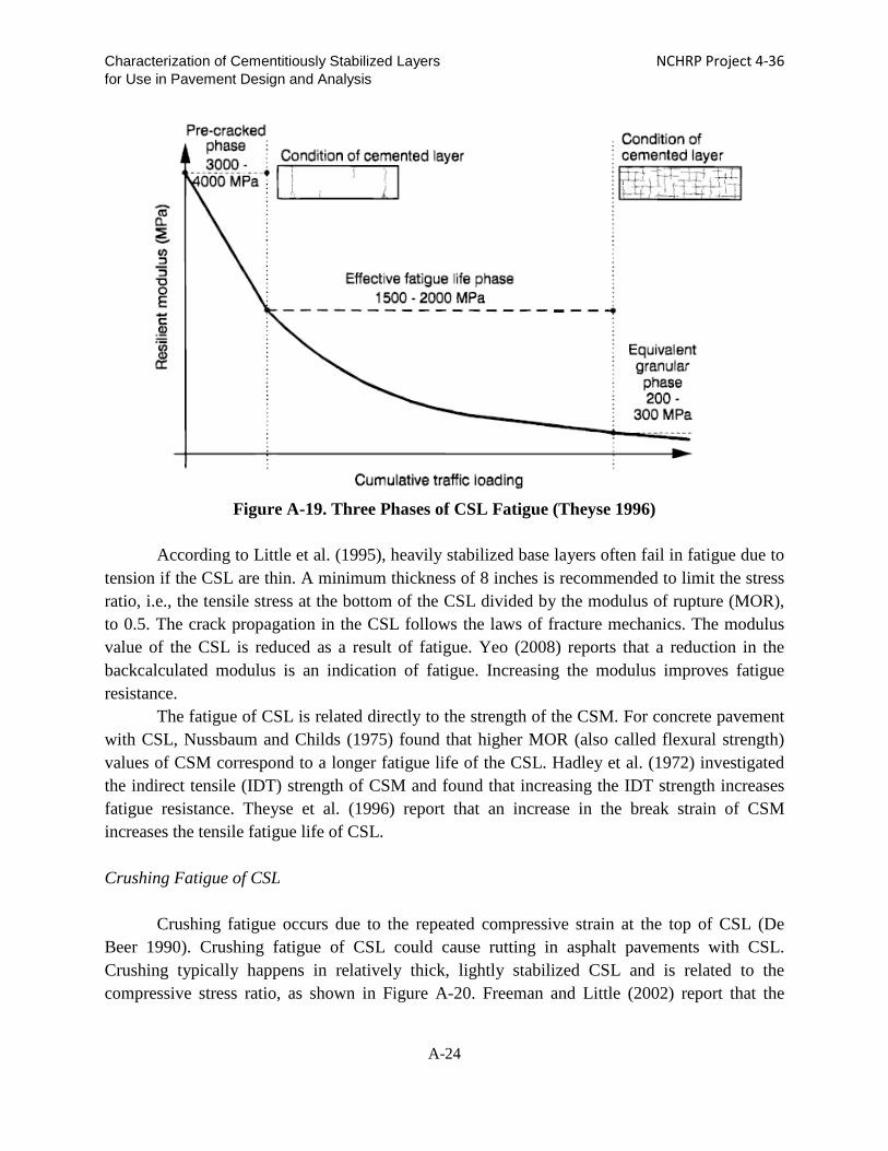
strain at the bottom of the CSL due to repeated traffic loads. Otte (1978) studied the fatigue cracking of CSL and reported that when the tensile stress exceeds 35% of the strength or a tensile strain level of more than 25% of the break strain in a flexural beam test, microcracking starts and the stress-strain relationship becomes nonlinear. Microcracks initiate at the bottom of the CSL and propagate upwards, as shown in Figure A-18. According to Theyse (1996), bottom tension fatigue consists of three phases, as shown in Figure A-19. De Beer (1990) reports that bottom-up cracking typically occurs in relatively thin CSL in which tensile strain could cause fatigue damage. The fatigue life in the laboratory is multiplied by a shift factor to account for traffic that occurs between the time of crack initiation and visible cracks. The bottom-up fatigue consists of three phases: (1) a pre-cracking phase (including shrinkage cracking) prior to fatigue initiation, (2) fatigue initiation and propagation, and (3) a post-cracking phase. The duration of the pre-cracking phase consumes about 20% of the life of the CSL. During fatigue propagation, the modulus of the CSL decreases due to fatigue damage. Permeability of the CSL increases as the number of loads increases due to cracks. The rate of degradation of the effective modulus is 52 ksi per 1 million loads for the wet state. In Phase 3, the CSL degrade into small pieces. The size of the degraded CSL depends on the strength of the CSM. After Phase 3, the disintegrated pieces could intrude into the underlying subgrade. During the post-cracking phase, the effective modulus value of the CSL is equivalent to that of the granular materials in terms of CSL thickness. When CSL is dry, the size of the equivalent granular materials is about 1.5 times of the CSL thickness and, after it is wet, the size is 0.3 times that of the CSL thickness. During the post-cracking phase, compressive strength and erodibility govern the rut depth.
A-22

Characterization of Cementitiously Stabilized Layers NCHRP Project 4-36 for Use in Pavement Design and Analysis
Figure A-17. Fatigue Cracking in CSL (Yeo et al. 2002)
Figure A-18. Fatigue Cracking in CSL Trenching (Moisture in Cracks) (Yeo 2008)
A-23
Characterization of Cementitiously Stabilized Layers NCHRP Project 4-36 for Use in Pavement Design and Analysis
Figure A-19. Three Phases of CSL Fatigue (Theyse 1996)
According to Little et al. (1995), heavily stabilized base layers often fail in fatigue due to
tension if the CSL are thin. A minimum thickness of 8 inches is recommended to limit the stress ratio, i.e., the tensile stress at the bottom of the CSL divided by the modulus of rupture (MOR), to 0.5. The crack propagation in the CSL follows the laws of fracture mechanics. The modulus value of the CSL is reduced as a result of fatigue. Yeo (2008) reports that a reduction in the backcalculated modulus is an indication of fatigue. Increasing the modulus improves fatigue resistance.
The fatigue of CSL is related directly to the strength of the CSM. For concrete pavement with CSL, Nussbaum and Childs (1975) found that higher MOR (also called flexural strength) values of CSM correspond to a longer fatigue life of the CSL. Hadley et al. (1972) investigated the indirect tensile (IDT) strength of CSM and found that increasing the IDT strength increases fatigue resistance. Theyse et al. (1996) report that an increase in the break strain of CSM increases the tensile fatigue life of CSL. Crushing Fatigue of CSL
Crushing fatigue occurs due to the repeated compressive strain at the top of CSL (De
Beer 1990). Crushing fatigue of CSL could cause rutting in asphalt pavements with CSL. Crushing typically happens in relatively thick, lightly stabilized CSL and is related to the compressive stress ratio, as shown in Figure A-20. Freeman and Little (2002) report that the
A-24

Characterization of Cementitiously Stabilized Layers NCHRP Project 4-36 for Use in Pavement Design and Analysis
failure of CSL is due to debonding between the CSL, fatigue on top of the CSL, and pumping of fines.
Figure A-20. Compressive Crushing Fatigue of CSL (De Beer 1990)
Durability of CSL and Related Pavement Performance
Stabilized material deteriorates as a result of environmental conditions such as freeze-
thaw cycles, wet-dry cycles, and erosion. Under freeze-thaw and wet-dry cycles, the strength and stiffness values of the CSL are reduced. As a result, resistance to fatigue cracking might be compromised. As shown in Figure A-21, freeze-thaw cycles can cause significant damage to CSM.
Laboratory studies indicate that freeze-thaw cycles significantly reduce the UCS and MOR of CSL (Wen and Ramme 2008, Naji and Zaman 2005, Dempsey and Thompson 1973). A field study by the research team for a previous project shows that, after seven years of service, the UCS in the middle of the traffic lane of CSL is less than 10% of the original strength (Wen and Ramme 2008). The loss of strength in the middle of the traffic lane indicates that the deterioration of CSL strength comes primarily from climatic conditions instead of traffic loads. In addition, the reduction of stiffness and strength causes high deflections and high stress levels in the surface layer, which results in bottom-up fatigue cracking in the surface layer.
Dempsey et al. (1984) studied the effects of freeze-thaw cycles on the properties of CSM and found that cooling and heating rates are important to freeze-thaw durability. In Illinois, most freeze-thaw cycles occur between December and February, with January having the most cycles. The average number of cycles is four per year in Illinois. The cooling rate is 0.15°F/hr and the
A-25

Characterization of Cementitiously Stabilized Layers NCHRP Project 4-36 for Use in Pavement Design and Analysis
heating rate is 0.30°F/hr. According to Bonnot (1991), durability can be evaluated in terms of expansion, loss of mass, residual strength or change of strength, or swelling.
Figure A-21. Material Degradation after Freeze-Thaw Cycles (Khoury 2005)
Swelling/Shrinkage of CSL and Related Pavement Performance
Expansive soil in any layer of a pavement system is detrimental to its performance,
creating problems such as dry-land cracking (Luo and Prozzi 2008). Cementitious stabilization often is used to mitigate the swell tendencies of expansive soil.
Expansive Soils
The volume change of expansive soils can cause dry-land cracking in an asphalt surface
layer. Therefore, expansive soils typically are stabilized. The U.S. Corp of Engineers (1994) define expansive soil as soil that swells more than 3 percent. The PI can be used to indicate the swell potential.
Wise and Hudson (1971) report that changes in moisture content in expansive soil cause swell and shrinkage. The study reports that moisture content below 6% is stable. Montmorillonite clay is expansive, and illite and kaolinite clay are not as expansive as montmorillonite. Lime treatment and pre-wetting mitigates swelling.
Petry and Jiang (2007) report that, after stabilization, total suction increases as a result of an increase in osmotic suction; however, swelling potential decreases. A WP4 Dewpoint potentiometer was used to measure total suction and osmotic suction. Beckham and Hopkins (2005) report that the stabilization of expansive soils by lime reduces swell. The heaving in HMA results from the expansion of untreated subgrade soil.
A-26

Characterization of Cementitiously Stabilized Layers NCHRP Project 4-36 for Use in Pavement Design and Analysis
Sulfate-Bearing Soils For sulfate-bearing soils, ettringite can form in the presence of moisture, calcium, sulfate,
and alumina, and can cause heave in a pavement, as shown in Figure A-22 and A-23. A sulfate concentration of 3,000 ppm in the soil is the threshold for swelling in sulfate-bearing soils (TxDOT 2005). When the concentration is less than 3,000 ppm, a traditional stabilization method can be used. When the sulfate concentration is between 3,000 ppm and 8,000 ppm, a single lime application, mellowing and additional moisture can be used. When it is higher than 8,000 ppm, removal and replacement or blending of non-plastic soils is recommended (Texas DOT 2005). Sulfate-induced swell can occur overnight with a sufficient source of moisture.
Vasudev (2007) reports that sulfate-bearing soils stabilized with Type V cement and fly ash exhibit the best field performance in terms of heaving resistance, followed by ground blast furnace slag.
Figure A-22. Swell of Sulfate-Bearing Soil Stabilized with Calcium-Based Additive (Texas
DOT 2005)
A-27

Characterization of Cementitiously Stabilized Layers NCHRP Project 4-36 for Use in Pavement Design and Analysis
Figure A-23. Sulfate-Bearing Soil (Texas DOT 2005)
As mentioned previously, many agencies often replace expansive soils with other soils.
The swelling issue is not investigated further in this study, as directed by the NCHRP panel.
Strength of Cementitiously Stabilized Materials and Related Pavement Performance
The strength of CSL directly controls their performance and thus affects overall pavement performance. Various strength measures of CSM are used to quantify their specific engineering behavior. The MOR is the key parameter in the fatigue failure of CSL. Tensile strength affects the development of shrinkage cracking in CSL. UCS is a key parameter for the top compression fatigue model. In addition, UCS tests often are used for the purpose of mix design.
Otte (1978) reports that the linear portion of the stress-strain curve in a flexural beam test reflects up to 35% strength of 25% break strain. The ratio between direct tensile strength and IDT strength is close to one. The Otte study also evaluates compressive strength, tensile strength, IDT strength, and bending strength. The bending test is recommended by Otte (1978) for fatigue study. Bonnot (1991) reports that in Europe, Spain uses the MOR, Italy uses IDT strength, and France uses tensile strength.
According to Theyse (1996), increasing the UCS reduces compression fatigue, and increasing the breaking strain decreases tension fatigue. The yield strength of damaged CSL is negatively related to the plastic strain of CSL. Thompson (1986) reports that an increase the
A-28

Characterization of Cementitiously Stabilized Layers NCHRP Project 4-36 for Use in Pavement Design and Analysis
MOR mitigates fatigue cracking. George (2001) reports that a low strength or low modulus/strength ratio is beneficial in mitigating shrinkage cracking.
Pretorius et al. (1972) report that flexural testing simulates field conditions better than direct tension testing. High confinement leads to high strength of the CSM but low failure strain. A sustained load that is larger than the critical stress (75% strength) can cause microcracks and eventual failure. Pretorius et al. also found that tensile strength is about one-tenth of UCS and one-fifth of MOR.
Stiffness of CSL and Related Pavement Performance
The stiffness (or modulus) of CSL is critical to the analysis of pavement and performance
prediction. Low stiffness of CSL may create high stress levels in the surface layer and, subsequently, fatigue cracking. However, HMA pavements with a very stiff base are prone to top-down cracking (ARA 2004). In general, high stiffness stems from high additive content, which also may cause high shrinkage rates. Therefore, the impact of stiffness (or modulus) must be studied to develop an appropriate stiffness range for pavement application. For stabilized subbase, high stiffness is generally not a concern. Stiffness of CSM refers to the resilient modulus, modulus of elasticity, flexural modulus, or IDT modulus, depending on the test mode.
Erodibility
Erosion can cause several issues in pavements with CSL, such as pumping of fines,
creating a loose layer between the surface layer and CSL, and accelerating the degradation of the CSL. Water can infiltrate the pavement structure through the shoulder and surface cracks or from underground. High dynamic pore pressure builds up with traffic loading, which loosens fine particles, reduces densities, and creates voids (De Beer 1990).
Wjvdm et al. (2001) report that the introduction of water accelerates permanent deformation and erosion. Vorobieff (1997) reports that, in order to prevent erosion, a minimum of 4% binder content is needed. Jung et al. (2009) report that concrete pavement on top of weak CSL does not perform well due to pumping. High-strength CSL have better pumping resistance than low-strengh CSL. Jung et al. introduced and developed erosion models and tests.
The damage to CSL by weathering and traffic also tends to accelerate erosion and pumping issues (Li et al. 1999, Meng et al. 2004). Thus, the durability of CSL is an essential property that affects pavement performance. Interface Bond
Even though it is not a material property, the interface bond between CSL and underlying
material restrains the free movement of the CSL due to shrinkage or expansion. Interface bonding thereby affects shrinkage crack spacing and width.
A-29

Characterization of Cementitiously Stabilized Layers NCHRP Project 4-36 for Use in Pavement Design and Analysis
Romanoschi and Metcalf (2001) report that the loss of a bond between HMA and CSL significantly increases the tensile strain at the bottom of the HMA layer. The bond between CSL and HMA is often lost due to the presence of water and erosion/crushing of the CSL surface. Shear failure occurs within the top of the CSL instead of at the interface of the CSL and HMA. The loss of the bond between the asphalt and CSL causes a shift in critical tension from the top of the subgrade to the bottom of the asphalt layer.
Wimsatt et al. (1987) report that increasing the interface bond strength between Portland concrete cement (PCC) and the base results in narrow crack spacing. The failure plane happens in CSL. The IDT strength of the CSL is correlated with the friction forces. Grogan et al. (1999) report that for concrete on top of CSL, asphalt emulsion does not work well as a bond breaker. Slippage and horizontal cracks are located below the interface of the concrete and CSL.
Wesevich et al. (1987) also report that for concrete pavement with CSL, friction at the interface results from adhesion, shearing and bearing. The soil cement base has the highest level of friction with a concrete surface, followed by the granular base, and asphalt and lime clay bases.
Based on the above discussion, the relationships between pavement performance and significant CSL properties are developed, as shown in Table A-1.
Table A-1. Matrix of the Relationship between Pavement Performance and Engineering
Parameters
CSL Properties
Distresses in Surface Layer
Rutting in Asphalt Layer
Block Cracking in Asphalt Layer
Bottom-Up Alligator
Cracking of Asphalt Layer
Transverse Cracking in
Asphalt Layer
Top-Down Longitudinal Cracking in Wheel Path
Heave
Transverse Cracking
of Concrete Pavement
Faulting of
Concrete Pavement
Stiffness/Modulus (+) CSL Base
(-) CSL
Base/Subbase
(+) CSL
Base/Subbase
Strength (+) CSL Base
(-) CSL
Base/Subbase (+)
CSL Base
Durability (freeze-thaw, wet-
dry)
(-) CSL
Base/Subbase
Fatigue Resistance
(-) CSL Base
(-) CSL
Base/Subbase
Erodibility Resistance
(-) CSL Base (-)
CSL Base (-) CSL Base
(-) CSL Base
Shrinkage Resistance (-)
CSL Base (-) CSL Base (-)
CSL Base
Swell Resistance (-)
CSL Base/Subbase
Note: “+” indicates a positive relationship; and “-”a negative relationship. For instance, increasing the modulus also increases the rutting potential in the asphalt layer (not pavement).
A-30

Characterization of Cementitiously Stabilized Layers NCHRP Project 4-36 for Use in Pavement Design and Analysis
CHAPTER A-3. LITERATURE REVIEW FOR PROPERTIES OF CSL
Strength and Modulus
The modulus of CSM is used in the pavement response model for the critical stress and strain analysis that is used in the performance models. The modulus of CSM can be obtained by conducting resilient modulus (Mr), modulus of elasticity (MOE), IDT modulus, flexural modulus (Ef), and seismic modulus tests. The current MEPDG recommends the use of the modulus of elasticity for heavily stabilized materials, such as cement-treated aggregate, and the resilient modulus for lightly stabilized materials, such as soil-lime, as the Level 1 input. For Level 2, the modulus is predicted from the UCS. The modulus of CSM is affected by many factors, as follows (AustROAD 2008, Foley 2002, Marais et al. 1973, Yeo 2008, Khoury 2005, Arora and Aydilek 2005):
• proportion of coarse angular aggregate • density • compaction moisture content up to OMC • binder content • age • efficiency of mixing • field moisture content • size of aggregate
Figure A-24 illustrates the effects of density on the modulus of CSM (Carteret 2009).
Figure A-24. Effect of Density on Flexural Modulus (Carteret et al. 2009)
A-31

Characterization of Cementitiously Stabilized Layers NCHRP Project 4-36 for Use in Pavement Design and Analysis
The strength of CSM often is used in performance prediction models. The strength of CSM can be obtained from MOR, IDT strength, UCS, and direct tensile tests. The strength of CSM is affected by many factors. Factors that affect the tensile strength of soil-cement include: molding water content, curing time, aggregate gradation, type of curing, aggregate type, curing temperature, compaction efforts, type of compaction, and cement content (Jayawickrama et al. 1998). It is reported that delayed compaction can reduce the strength of CSM. High levels of compactive effort lead to high UCS values. Increasing the water content decreases the UCS (Bhattacharja and Bhatty 2003). Increasing the cement content increases the UCS and resilient modulus values (Arora and Aydilek 2005). Increasing the fines content up to 30% increases the resilient modulus of lightly stabilized soil and the UCS (Ashtiani et al. 2007).
Relationships between the modulus and strength of CSM are reported, as follows. For soil-cement: Mr = 1245×UCS+300 (Foley 2002) Eq. (A-1) Mr = 0.2×UCS; UCS = 0.028×MOE-1142.6 (psi) (Miller et al. 2006) Eq. (A-2) Mr = 1245×UCS+300 (AustROAD 2008) Eq. (A-3) Ef (28d) = k×UCS (28-day), and k = 1000~1250 (AustROAD 2008) Eq. (A-4) Mr = 62.5×UCS(7-day) 0.5 (Scullion et al. 2008) Eq. (A-5) MOE(t) = 4.38×w1.5×UCS0.75 where w is water content (Lim and Zollinger 2003) Eq. (A-6) Mr = 5.2851×UCS(7-day)0.5 (Scullion et al. 2008) Eq. (A-7) For lime/fly ash: Mr = 696×UCS2-222×UCS for lime/fly ash (1:3) (Foley 2002) Eq. (A-8) Mr = 574×UCS2+564×UCS for lime/fly ash (1:1) (Foley 2002) Eq. (A-9) For soil-lime: IDT strength = 0.13×UCS; Mr = 0.25×UCS (Little 1999) Eq. (A-10) Mr = 0.124×UCS+9.98 (ARA 2004) Eq. (A-11) For full-depth reclaimed materials:
Mr = 7.3× (E/1200)0.5 (Barnes 2008) Eq. (A-12)
Figure A-25 shows the relationship between UCS and IDT strength (Kennedy and Hudson 1973), and Figure A-26 shows the relationship between the MOR and the resilient modulus (Mr) (Sobhan and Krizek 1998).
A-32

Characterization of Cementitiously Stabilized Layers NCHRP Project 4-36 for Use in Pavement Design and Analysis
Figure A-25. Relationship between UCS and IDT Strength (Kennedy and Hudson 1973)
Figure A-26. Relationship between Flexural Strength (MOR) and Resilient Modulus
(Sobhan and Krizek 1998)
A-33

Characterization of Cementitiously Stabilized Layers NCHRP Project 4-36 for Use in Pavement Design and Analysis
In addition, good correlation is found between the seismic modulus and resilient modulus, as shown in Figure A-27.
Figure A-27. Correlation between Seismic Modulus and Resilient Modulus (Hilbrich and
Scullion 2007)
Strength values obtained from different test modes can be related, but the modulus and strength values can only be related for a specific material (Carteret 2009). In addition, the strength and modulus of CSM continue to grow as the materials age. Little and Nair (2007) report that for soil-lime, the UCS increases by 3.2 times from 28 days to 26 weeks and in another cases by 11 times from 60 days to 180 days.
Wang and Hudson (1972) use the following formula to predict the direct tensile strength of soil-cement.
Direct tensile strength = [0.5+60C1.33/(32+C1.33)][1+(2log(t/92))2.67+(log(t))2.67] Eq. (A-13)
where C = cement content, %, and t = curing time, days. The U.S. Air Force also provides a prediction equation to estimate the growth of UCS of
soil-cement, as follows. UCS(t)=UCS(t0)+Klog(t/t0) Eq. (A-14)
where A-34

Characterization of Cementitiously Stabilized Layers NCHRP Project 4-36 for Use in Pavement Design and Analysis
K = 70C for granular soils and 10C for fine-grained soils, t is the number of curing days, and C is the cement content (%).
Kim and Zollinger (2003) developed a prediction equation to estimate initial strength of
concrete based on 28-day strength:
f(t)=f(28)(t/[2.5+0.9t] Eq. (A-15)
where f(t) = UCS earlier than 28 days. t = days since the compaction of CSM within 28 days. The modulus of CSM reduces as a result of fatigue damage or weathering. After
complete damage (i.e., failure), the modulus of CSM is equivalent to the modulus of granular materials. The U.S. Army Corps of Engineers developed a relationship between the deteriorated modulus of CSL and the original strength of CSM, as shown in Figure A-28.
Figure A-28. Relationship between Equivalent Cracked Modulus of CSL and Original UCS
of CSM (Department of the Army and the Air Force 1994)
The above relationship can be approximated by Eq. (A-16): 𝐸𝐸𝑐𝑐𝑐𝑐𝑐𝑐(𝑚𝑚𝑚𝑚𝑚𝑚) = 10(1.5529 𝑙𝑙𝑙𝑙𝑙𝑙 (𝑈𝑈𝑈𝑈𝑈𝑈28)+0.4132 ) Eq. (A-16)
where
ECSM = minimum CSL modulus, ksi UCS28 = UCS after 28-day curing, psi
A-35

Characterization of Cementitiously Stabilized Layers NCHRP Project 4-36 for Use in Pavement Design and Analysis
Durability
The CSL are subjected to weathering in the field, such as wetting and drying, freezing and thawing, moisture susceptibility and erosion, which must be characterized.
Wetting and Drying
Wetting and drying affect the strength and modulus values of CSM. Typically, the
modulus and strength values reduce as the number of wetting and drying cycles increases (Paige-Green 1998, Zaman et al. 1999, Khoury and Zaman 2007, Ling et al. 2008, Scullion et al. 2008). However, after a certain number of cycles, the strength and modulus values reach their minimum values. Zaman et al. (1999) found that the resilient modulus reaches its minimum value, which is about 60% of the original modulus value, after 8 cycles of wetting and drying, and 60% of the original UCS after 4 cycles. In another study by Khoury and Zaman (2007), the minimum modulus value after wetting and drying cycles is about 30% of the original modulus value. In addition, wetting and drying can also lead to susceptibility of CSM to erosion (Van Wijk 1985, De Beer 1993, Ras and Visser 2004, Scullion 2005).
In summary, wetting and drying significantly affect the performance of CSL and should be considered in pavement design and analysis.
Freezing and Thawing
Freezing and thawing also affect the performance of CSL. It is reported that freeze-thaw
cycles significantly reduce the resilient modulus, flexural modulus, MOR, and UCS values (Khoury 2005, Paige-Green 1998, Zaman et al. 1999). Figure A-29 shows the effects of freezing and thawing on the MOR (Khoury 2005). After a certain number of freeze-thaw cycles, the reduction of the strength and modulus is not pronounced (Esmer et al. 1969, Thompson and Dempsey 1977, Zaman et al. 1999) because freezing and thawing increase the pore size, reducing the damaging effects of later freeze-thaw cycles (Esmer et al. 1969). Freeze-thaw cycles also are used in the mix design of stabilized materials (Portland Cement Association 1992). The mass loss after 12 freeze-thaw cycles is one of the design criteria. Freeze-thaw durability is significantly affected by the original UCS of the CSM. According to the PCA, 95% of CSM samples with UCS values of 750 psi or higher can pass the freezing and thawing design criteria. Table A-2 lists the design criteria used by the U.S. Army Corps of Engineers.
A-36

Characterization of Cementitiously Stabilized Layers NCHRP Project 4-36 for Use in Pavement Design and Analysis
Table A-2. Durability Criteria for CSM (Corp of Engineers 1994)
Figure A-29. Effects of Freeze-Thaw Cycles on the MOR (Khoury 2005)
Moisture Susceptibility
Moisture conditioning significantly affects the performance of CSL, especially for lightly
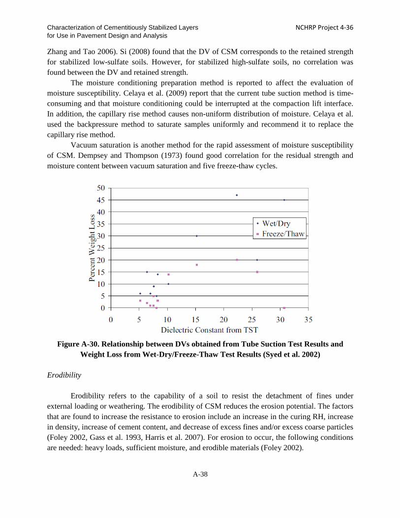
stabilized materials (Celaya et al. 2009, Dempsey and Thompson 1973) in terms of strength and modulus. The moisture conditioning of CSM can be applied through soaking, backpressure saturation, vacuum saturation, or capillary rise. The retained UCS after moisture conditioning has been used in the mix design in Texas (Geiger et al. 2007). The moisture conditions used in Texas are drying at 104°F for 2 days followed by capillary saturation for 8 days or 4-day soaking. Recently, the dielectric value (DV) based on the tube suction method has been used as a rapid assessment of moisture susceptibility of stabilized materials after the CSM are subjected to capillary rise. An increase in the DV is found to correspond to a decrease in the residual UCS (Zhang and Tao 2006) and wetting-drying brushing results (Syed et al. 2003), as shown in Figure A-30. A DV lower than 10 indicates good durability of the CSM (Barbu 2004). The capillary rise is affected by pore distribution, initial moisture content, and the infiltration process (Foley 2002,
A-37
Characterization of Cementitiously Stabilized Layers NCHRP Project 4-36 for Use in Pavement Design and Analysis
Zhang and Tao 2006). Si (2008) found that the DV of CSM corresponds to the retained strength for stabilized low-sulfate soils. However, for stabilized high-sulfate soils, no correlation was found between the DV and retained strength.
The moisture conditioning preparation method is reported to affect the evaluation of moisture susceptibility. Celaya et al. (2009) report that the current tube suction method is time-consuming and that moisture conditioning could be interrupted at the compaction lift interface. In addition, the capillary rise method causes non-uniform distribution of moisture. Celaya et al. used the backpressure method to saturate samples uniformly and recommend it to replace the capillary rise method.
Vacuum saturation is another method for the rapid assessment of moisture susceptibility of CSM. Dempsey and Thompson (1973) found good correlation for the residual strength and moisture content between vacuum saturation and five freeze-thaw cycles.
Figure A-30. Relationship between DVs obtained from Tube Suction Test Results and
Weight Loss from Wet-Dry/Freeze-Thaw Test Results (Syed et al. 2002)
Erodibility
Erodibility refers to the capability of a soil to resist the detachment of fines under external loading or weathering. The erodibility of CSM reduces the erosion potential. The factors that are found to increase the resistance to erosion include an increase in the curing RH, increase in density, increase of cement content, and decrease of excess fines and/or excess coarse particles (Foley 2002, Gass et al. 1993, Harris et al. 2007). For erosion to occur, the following conditions are needed: heavy loads, sufficient moisture, and erodible materials (Foley 2002).
A-38

Characterization of Cementitiously Stabilized Layers NCHRP Project 4-36 for Use in Pavement Design and Analysis
Van Wijk (1985) reports that material gradation and permeability affect the erodibility of materials. Material particles larger than 0.4 inch do not pump. For an open-graded subbase, the pore water pressure is less than 0.3 psi with velocity of 6.6 ft/sec or less. For dense-graded materials, the pressure is up to 3 psi with velocity of 22.6 ft/sec. Erodibility of stabilized materials depends on binder content, water content, and environmental effects (e.g., freezing and thawing). The water pressure also is affected by the speeds and loads of passing vehicles, deflections, and voids under the slab. Water pressure is higher at higher traffic speeds; water pressure increases with an increase in traffic speed up to 22 miles/hour and then decreases. Large deflections cause high levels of water pressure. Curled slabs exhibit high water pressure levels up to 5.8 psi. Pressure is found to be higher when load was on leave slab. The shear stress of water caused by a moving truck (42,000 lbs) is about 2 psi at 60 miles/hour. An automobile produces water pressure of 0.5 psi. Therefore, most erosion occurs due to moving truck traffic instead of automobile traffic. Van Wijk proposes a critical shear strength of 3.6 psi. It is seen that the water pressure level is relatively low compared to the strength of most CSM. Therefore, as reported in the literature (Foley 2002), the presence of impacts from heavy loads is a required condition for erosion to occur.
The UCS often is used to indicate the performance of CSL. It is reported that a strong correlation exists between UCS and erosion (Gass et al. 1993, Barbu 1994). A minimum 7-day UCS of 300 psi is deemed to be sufficient to resist erosion. In addition, wet/dry brush test results correlate with the critical shear stress of materials (Gass et al. 1993). The moisture susceptibility of CSM, i.e., the DV obtained from tube suction test results, also is found to correlate with the erosion potential of CSM (Barbu 1994), as indicated by wheel abrasion test results (Syed et al. 2000).
For erosion to occur, the shear stress caused by moving water must exceed the critical shear stress, as shown in Figure A-31. It is found that the critical shear stress is related to the saturated, undrained soil shear strength (Leonard and Richard 2004, Indraratna et al. 2008), which is typically half of the UCS. Adding binder increases the erosion resistance of CSM. There is a critical cement content below which erosion will occur. Curing time, soaking, delay of compaction, cement content and the number of freeze-thaw cycles are found to affect erosion (Howard 1988). Brushing after wetting and drying also is used to assess the erodibility of CSM in term of mass loss (Paige-Green 1998).
A-39

Characterization of Cementitiously Stabilized Layers NCHRP Project 4-36 for Use in Pavement Design and Analysis
Figure A-31. Relationship between Hydraulic Shear Stress and Erosion Rate (Indraratna
2008)
Fatigue
Fatigue occurs as a result of repeated loads caused by traffic. According to AustROAD (2008), the fatigue resistance of CSM can be reduced by:
• a decrease in the modulus value • a decrease in the density • an increase in moisture content • insufficient mixing.
The fatigue life of CSL typically is related to the stress ratio (applied tensile stress over
MOR) or the strain ratio (applied tensile strain over breaking strain) (AustROAD 2008, ARA 2004, Otte 1978, Sobhan and Mashnad 2000, Yeo 2008). When beam tests are used to obtain the fatigue life of CSM, the number of cycles to 50% of the initial modulus value is considered to be the fatigue life (Yeo 2008).
The MOR of CSM is used to predict the fatigue performance of CSM (ARA 2004, Sobhan and Mashnad 2000). The flexural modulus is found not to be a significant variable for the fatigue model, whereas the breaking strain is a significant variable. The strain ratio, or strain level in the case of relatively constant breaking strain, is more applicable to different materials (Carteret 2009). Figure A-32 shows the relationship between fatigue life and strain level.
A-40

Characterization of Cementitiously Stabilized Layers NCHRP Project 4-36 for Use in Pavement Design and Analysis
Figure A-32. Relationship between Fatigue Life and Initial Strain (Carteret 2009)
Shrinkage
Shrinkage cracking occurs as a result of contraction of CSM that are restrained by the
underlying materials. Shrinkage cracking can reflect through the surface layer and allow the ingress of surface water. The shrinkage cracking of CSL can be reduced by (AustROAD 2008, George 1968):
• the immediate application of a curing coat • a lower binder content • the use of slow-setting binder • a lower fine clay content (<20% 0.003 in fines and PI <20) • pretreating with lime or lime+cement • adding gravel or rock.
Queensland in Australia uses the following specifications to reduce shrinkage (Scullion et al. 2005):
• Linear shrinkage of raw soil passing the #40 sieve: 2.5% maximum • Plasticity index: 4% maximum • Introduction of a fly-ash blend cement • Percentage of fines passing #200 sieve: 7.0% maximum
A-41
Characterization of Cementitiously Stabilized Layers NCHRP Project 4-36 for Use in Pavement Design and Analysis
• Linear shrinkage of cement-treated base material should not exceed 250 microstrain after 21 days.
Scullion et al. (2005) report that typical shrinkage cracking spacing is between 3 ft. and
60 ft. The crack width is affected by temperature. Little (1999) found that in summer, the backcalculated modulus value of CSL with a crack width less than 0.1 inch is about half of the backcalculated modulus value of CSL without cracks. However, in winter, the modulus value at a cracked area is one-third of the modulus value at an area without cracks.
A-42

Characterization of Cementitiously Stabilized Layers NCHRP Project 4-36 for Use in Pavement Design and Analysis
CHAPTER A-4. TEST PROCEDURES FOR CSM PROPERTIES
The proper characterization of the properties of CSM is important for selecting appropriate CSM and predicting the field performance of CSL. Different test procedures are available to measure these properties and need to be evaluated for selection.
Strength Tests
The strength values of CSM can be obtained through UCS, IDT strength, MOR, direct
tensile or direct shear tests.
Unconfined Compressive Test
The UCS test is the most common test performed on CSM to determine the suitability of the mixtures for uses such as in pavement bases and subbases, stabilized subgrades, and structural fills. Most state highway agencies use the UCS test for their mix designs and for quality assurance (QA) and quality control (QC) because of the simplicity of the test. The UCS test is well-established and meets all cost, practicality and availability requirements (Yeo et al. 2002). Tensile strength can be estimated conservatively as 10% of the UCS, and the MOR can be estimated conservatively to be twice the tensile strength or approximately 20% of the UCS (Little 1999). Several correlations have been developed between UCS and the resilient modulus (Camargo et al. 2009, Thompson 1970, Dallas et al.). Typically, AASHTO T22, ASTM D1633, AASHTO T220, and ASTM C593 are used to test lean concrete, soil cement, lime-stabilized materials, and fly ash-stabilized materials with or without lime, respectively.
The UCS value is the peak load divided by the cross-section of a cylindrical specimen, except for soil-lime for which the enlargement of the cross-section during loading is taken into account. The typical height-to-diameter ratio of a UCS specimen is two. Otherwise, a correction factor must be used to obtain a meaningful strength. Figure A-33 presents the UCS test setup.
• For lean concrete, the loading rate in AASHTO T22 is displacement-controlled, which corresponds to 35+/-7 psi per second. The ratio of height to diameter is 1.75 or higher. Otherwise, a correction factor should be used.
• For soil-cement, the specimen size is either 4 inches in diameter by 4.6 inches in height or 2.8 inches in diameter and 5.6 inches in height according to ASDTM D1633. For the specimen with a 4-inch diameter and 4.6-inch height, a correction factor of 0.909 is used to convert the strength to that of a specimen with a height-to-diameter ratio of 2.0. The preparation of soil-cement specimens is based on ASTM D1632. Capping is required for soil-cement specimens. The test is conducted using either displacement-controlled, 0.05 in./min, or stress-controlled, 20 psi per second. Prior to the testing, the specimen is subjected to 4-hour soaking.
A-43

Characterization of Cementitiously Stabilized Layers NCHRP Project 4-36 for Use in Pavement Design and Analysis
• For soil-lime, AASHTO T220 specifies a specimen size of 6 inches in diameter and 8 inches in height. The loading rate is 0.13-0.15 in./min. Prior to compression testing, the specimen is subjected to 7-day curing at room temperature, 6-hour drying at 140°F, and 10-day capillarity with confining pressure. The UCS is determined as follows:
𝑈𝑈𝑈𝑈𝑈𝑈 = 𝑃𝑃𝑃𝑃𝐴𝐴ℎ
Eq. (A-17)
where P = total vertical load d = deformation after testing A = cross-section of specimen before testing H = height of specimen before testing.
• For high calcium fly ash, such as Class C fly ash, or low calcium fly ash and lime-stabilized materials, ASTM C593 recommends the use of ASTM C39/C39M, Test Method for Compressive Strength of Cylindrical Concrete Specimens, which is equivalent to AASHTO T22. Prior to the unconfined compression test, the specimen is subjected to 7-day curing at 100°F and 4-hour soaking. The specimen geometry is 4 inches in diameter and 4.6 inches in height.
Figure A-33. Unconfined Compressive Strength Test Setup
IDT Strength Test
The IDT strength test involves loading a cylindrical specimen with compressive loads
distributed along two axial lines that are diametrically opposite, as shown in Figure A-34. This loading setup results in a relatively uniform tensile stress perpendicular to and along the diametric plane. Failure occurs by splitting along this loaded plane.
A-44

Characterization of Cementitiously Stabilized Layers NCHRP Project 4-36 for Use in Pavement Design and Analysis
The IDT strength can be calculated as follows:
𝑈𝑈(𝑡𝑡) = 2𝑃𝑃𝜋𝜋𝜋𝜋𝑃𝑃
Eq. (A-18)
where S(t) = IDT strength P = peak load t = height of specimen d = diameter of specimen. From a review of the literature concerned with the evaluation and use of IDT strength, a
number of advantages and disadvantages are found. The six major advantages attributed to the test are as follows (Hudson and Kennedy 1968):
• It is relatively simple. • The type of specimen and equipment are the same as that used for compression testing. • Failure is not seriously affected by sample end conditions. • Failure is initiated in a region of relatively uniform tensile stress. • The coefficient of variation (COV) of the test results is low. • Mohr’s theory is a satisfactory means of expressing failure conditions for brittle
crystalline materials.
In addition, according to Yeo et al. (2002), the IDT strength test is practical, productive, economic, and user-friendly. Besides strength, the IDT strength test can also be used to measure the modulus, Poisson’s ratio, fatigue, and permanent deformation (Gnanendran and Piratheepan 2008). The IDT test is also suitable for lightly stabilized materials (Yeo 2002).
The IDT strength values for concrete can be obtained using AASHTO T198, Splitting Tensile Strength of Cylindrical Concrete Specimens, or ASTM C496, Standard Test Method for Splitting Tensile Strength of Cylindrical Concrete Specimens. The specimen geometry is 6 inches in diameter and 12 inches in height. The loading rate of the splitting tensile stress is 100-200 psi/min. The size and loading rate may not be appropriate, however, for soil-lime or soil-fly ash/lime, which is relatively weak material. The Australian method (Midgley and Yeo 2008) to test for IDT strength of stabilized materials uses specimens either 4 inches or 6 inches in diameter, which is dependent on the maximum particle size. The loading rate is 4500 ±450 lbs/min. For CSM, neither composition nor width of the loading strip make any difference to the test results (Hudson and Kennedy 1968).
A-45

Characterization of Cementitiously Stabilized Layers NCHRP Project 4-36 for Use in Pavement Design and Analysis
Figure A-34. IDT Test Setup (Yeo 2008)
Modulus of Rupture Test
The MOR is a direct measurement of the resistance of CSL to bending and cracking. In
the MOR test, a beam specimen is subjected to a bending load at a constant stress rate until failure, as shown in Figure A-35. For Level 1 input in the MEPDG, the MOR from AASHTO T97, Standard Method of Test for Flexural Strength of Concrete (Using Simple Beam with Third-Point Loading), or ASTM D1635, Standard Test Method for Flexural Strength of Soil-Cement Using Simple Beam with Third-Point Loading, is required for heavily stabilized materials for flexible pavement design (ARA 2004). For Level 2, MOR can be estimated from the UCS. The MOR from a third-point beam test can be determined using the following formula:
𝑀𝑀𝑀𝑀𝑀𝑀 = 3𝐹𝐹𝐹𝐹
2𝑏𝑏𝑃𝑃2 Eq. (A-19)
where
F = the load (force) at the fracture point L = the length of the support span b = width d = thickness. The beam test is good for high-stiffness CSM. However, the moderate and low-stiffness
specimens may break during handling. In addition, the beam sample is difficult to prepare (Yeo et al. 2002). In early Australian tests (Midgley and Yeo 2008), the flexural beam test was not planned to be used due to the perceived difficulty of extracting field beam samples from the road
A-46

Characterization of Cementitiously Stabilized Layers NCHRP Project 4-36 for Use in Pavement Design and Analysis
bed. However, after some trials and improvements, a routine procedure was developed that enables beam samples to be readily obtained. For the MOR test, the sample is loaded with a seating force of 11 lbs for the first 6 seconds, after which the load is increased at a rate of 742 lbs/min until the sample fails, as described in Australian Standard AS1012.11–2000. The results from the MOR tests tend to overestimate the tensile strength of concrete by 50% to 100%, mainly because the flexure formula assumes a linear stress-strain relationship throughout the cross-section of the beam. Additionally, in direct tension tests the entire volume of the specimen is under applied stress, whereas in the flexure test only a small volume of the material near the bottom of the specimen is subjected to high stress levels. With low-strength concrete, the MOR can be as high as twice the strength in direct tension (Kumar et al. 2006). Nevertheless, the test is favored by many engineers because the loading conditions are similar to those in the field for pavement materials (Hudson and Kennedy 1968).
Figure A-35. MOR Test Setup (Yeo 2008)
Direct Tensile Strength Test
Direct tensile strength is used to characterize CSM (Raad 1977, Otte 1978). Direct tensile
strength tests subject a specimen to a tensile force with constant movement or load rate. The direct tensile test simulates the field conditions when the material is subjected to pure tension, (Hudson and Kennedy 1968), such as the case of thermal contraction or drying shrinkage in the field. Direct tensile tests can be conducted in accordance with ASTM D2936–08, Standard Test Method for Direct Tensile Strength of Intact Rock Core Specimens. However, the test has many limitations, including a long preparation time (about 3 hours), misalignment for pure tension, and failure outside the central portion (Yeo et al. 2002). In addition, the method that is used to grip the specimen is also challenging (Gnanendran and Piratheepan 2008). All these factors contribute to lack of practicality and repeatability. Chakrabarti and Kodikara (2008) modified the
A-47

Characterization of Cementitiously Stabilized Layers NCHRP Project 4-36 for Use in Pavement Design and Analysis
tensile strength test setup (Figure A-36). However, this configuration still is subjected to bending stress.
Figure A-36. Modified Tensile Strength Test (Chakrabarti and Kodikara 2007)
Modulus Tests
Currently, the MEPDG requires the resilient modulus for lightly stabilized materials (e.g.,
materials stabilized with fly ash or lime) and the modulus of elasticity for heavily stabilized materials, (e.g., lean concrete, soil-cement). For Level 2 input in the MEPDG, the resilient modulus and modulus of elasticity can be predicted from the UCS. Both the resilient modulus and modulus of elasticity are used in pavement analysis for stress/strain determination. The resilient modulus of lightly stabilized materials has some dependence on stress levels and is sensitive to the test procedure.
Resilient Modulus Test
The resilient modulus (Mr) is the ratio of applied cyclic deviator stress to recoverable
strain. Laboratory resilient modulus testing of unbound aggregate bases or subgrade soils is performed by methods such as found in NCHRP 1-28A, AASHTO T-307, or the LTPP test protocol P46. The current MEPDG recommends the use of AASHTO T-307. The resilient modulus test is conducted in a load frame fitted with a hydraulic load actuator with a servo-hydraulic control system capable of delivering rapidly varying loads, as shown in Figure A-37.
𝑀𝑀𝑟𝑟 = 𝜎𝜎𝑑𝑑𝑑𝑑
𝜀𝜀𝑟𝑟 Eq. (A-20)
where
σdN = the cyclic deviator stress of the Nth load pulse εr = the resilient deformation from σdN.
A-48

Characterization of Cementitiously Stabilized Layers NCHRP Project 4-36 for Use in Pavement Design and Analysis
The resilient modulus test simulates field conditions, such as stress level and traffic
loading (Little and Nair 2007). However, the resilient modulus test setup is very time-consuming and tedious in nature. The mounting of sensors is difficult, and the noise level in the system makes it hard to run on a routine basis (Hilbrich and Scullion 2007). Also, the test equipment is expensive, and the test procedures are very difficult to run. The existing test procedures were developed for granular or low-stiffness materials. When testing stiff materials, it is critical to cap the samples. Even with very good control, problems are likely to be encountered with the displacements in the LVDTs (Hilbrich and Scullion 2007). The COV is reported to be 10% or higher (Scullion et al. 2008).
Figure A-37. Resilient Modulus Test Setup (AASHTO T307)
Modulus of Elasticity Test
For heavily stabilized materials, the modulus of elasticity (based on ASTM C 469) is
specified in the MEPDG. The ASTM method consists of failing a cylindrical specimen using a constant stress rate, as shown in Figure A-38. The test method provides a stress-to-strain ratio and a lateral-to-longitudinal strain ratio. Because the test protocol is designed for concrete or heavily stabilized materials, some development is needed for lightly stabilized materials. Richardson (1996) conducted the modulus of elasticity test on soil-cement and reported the COV as 16.3 percent.
A-49

Characterization of Cementitiously Stabilized Layers NCHRP Project 4-36 for Use in Pavement Design and Analysis
Figure A-38. Modulus of Elasticity Test Setup (ASTM C469)
Flexural Stiffness Test
Flexural stiffness is obtained by applying cyclic loads to a beam specimen without
damaging the specimen. The flexural stiffness can be calculated as follows:
𝐸𝐸 = 𝐹𝐹𝐹𝐹3
2𝑤𝑤ℎ3𝑃𝑃 Eq. (A-21)
where
F = applied force L = support span of beam specimen w = width of beam specimen h = height of beam specimen d = deflection of specimen at mid-span. Flexural stiffness is used extensively in Australia for CSM (Yeo 2008). It simulates the
field bending of CSL (AustROAD 2008, Yeo 2008) and is suitable for high-stiffness CSM. However, the beam sample is difficult to prepare and handle, especially for lightly stabilized materials (Yeo 2002, Gnanendran and Piratheepan 2008). The results of flexural stiffness tests also show some variation with a COV typically below 20 percent (Yeo 2008, Carteret 2009).
IDT Modulus Test
The IDT modulus test involves placing a cylindrical sample horizontally along its axis
with compression loading applied vertically across the diameter of the specimen. Induced tensile strains are measured horizontally across the diameter. The IDT modulus can be determined based on the following equation (Midgley and Yeo 2008):
A-50

Characterization of Cementitiously Stabilized Layers NCHRP Project 4-36 for Use in Pavement Design and Analysis
𝐸𝐸 = 𝑃𝑃 × (𝜗𝜗+0.27)
𝐻𝐻×ℎ𝑐𝑐 Eq. (A-22)
where
P = peak load 𝜗𝜗= Poisson’s ratio H = recovered horizontal deformation of specimen after application of load hc = height of specimen. The IDT modulus value is higher than the beam modulus value (Yeo 2008). Yeo et al.
(2002) report that the Australian IDT test is suitable for determining the strength and stiffness of stabilized materials. Cylindrical test specimens are considered to be the most practical both in terms of laboratory compaction and field sampling via coring techniques. In addition, this test is practical, cost-effective, has good equipment availability, requires basic sample preparation and provides for the preferred tensile mode of failure for both the strength and fatigue tests. Currently, there is no test standard to determine the IDT modulus of CSM. The Australian test method for the IDT modulus of CSM has been evaluated (Midgley and Yeo 2008). To determine the specimen IDT modulus, 50% or less of the ultimate failure load determined using the IDT strength test is used such that the material remains within its elastic range. The displacement is measured by LVDTs.
The COV of the IDT modulus is reported to be less than 20 percent (Carteret 2009). The location of the LVDTs is found to affect the test results significantly. By using internal LVDTs, the COV can be reduced significantly (Gnanendran and Piratheepan 2008).
Seismic Modulus Test
The seismic modulus (or vibration) test (Tex-147-E or ASTM C 215) is a simple,
nondestructive laboratory test for determining the moduli of pavement materials. The modulus measured using this method is the low-strain seismic modulus (SM). This method was developed originally for testing PCC specimens. With appropriate modifications in the hardware and software, it is now also applicable to specimens composed of stabilized base and subgrade materials. The procedure used in the seismic modulus test involves finding the Young’s modulus by measuring the velocity of an elastic wave that propagates through a cylindrical specimen. Figure A-39 presents the test setup.
The seismic modulus test shows potential because it is relatively inexpensive and rapid. However, if the design program requires the use of resilient modulus values, then a modulus correction factor must be developed for unbound materials. It is reported that the seismic modulus test provides more repeatable data for estimating the resilient modulus of stabilized materials (Whitehurst and Yoder 1952, Si 2008). The seismic modulus is found to correlate with the resilient modulus of stabilized materials, and a COV of 7% is reported (Scullion et al. 2008).
A-51

Characterization of Cementitiously Stabilized Layers NCHRP Project 4-36 for Use in Pavement Design and Analysis
Table A-3 provides a comparison of the seismic modulus and resilient modulus test procedures and equipment. The seismic modulus values are reported to be about 1.7 times those obtained from the FWD (Geiger et al. 2007).
Table A-3. Comparison of Resilient Modulus and Seismic Modulus Test Methods and
Equipment (Hilbrich and Scullion 2007) Seismic Modulus
Test Resilient Modulus
Test Equipment cost $4,000 $350,000 Test set-up time 2 min 1 h
Testing time 3 min 5 min* Plaster capping required No Yes
*Although the source indicates 5 min, the Mr test typically takes 3-4 hours.
Figure A-39. Seismic Modulus Test Setup (Guthrie et al. 2001)
Ultrasonic Pulse Velocity Test
The ultrasonic pulse velocity test (ASTM C597), also called the acoustic modulus test, is a nondestructive testing technique that transmits sound waves ranging in frequency from 20 kHz to 1 GHz through the specimen. By measuring the travel time through the specimen, the p-wave or shear wave velocity and related dynamic properties of the material are determined. Since 1970s, ultrasonic pulse velocity has been developed and widely used as a simple and quick measurement for quality control and defect detection in civil infrastructure. The method is simple and quick and attractive for application to soils. Figure A-40 shows a schematic view of the pulse velocity test apparatus (ASTM C597).
A-52

Characterization of Cementitiously Stabilized Layers NCHRP Project 4-36 for Use in Pavement Design and Analysis
Figure A-40. Schematic of Pulse Velocity Test Apparatus (ASTM C597)
Yesiller et al. (2001) evaluated the feasibility of applying ultrasonic pulse velocity testing
to stabilized materials. Their p-wave measurement system consisted of a 50-kHz p-wave transducer, receiver, and data acquisition system. They calculated the first arrival time as the difference between the time of application of the pulse by the transmitting transducer and the arrival time of the signal at the receiver. These researchers conducted tests on lime, cement, and fly ash-stabilized clays with high plasticity. They applied the ultrasonic pulse velocity test method to monitor the strength growth of the specimens in terms of curing time. In general, Yesiller et al. found that velocity increases with curing time, and the p-wave increases more in the first seven days than during the rest of the curing period. Cement mixtures show larger increasing rates of p-waves and higher velocities during curing. Additionally, Yesiller et al. investigated the effect of compaction moisture content on p-wave velocity. They measured the maximum p-wave velocity for specimens compacted at the optimum moisture content. For clay-cement and compacted clay specimens, the variation in p-wave velocities with compaction moisture content followed the same trend as the variation in dry density with compaction moisture content. However, this trend was not observed in the fly ash-stabilized clay. Good correlations were observed between velocity and strength for fly ash-stabilized soil. The p-wave velocity increased with the increasing modulus value of the mixture. Yesiller et al. (2001) conclude that p-wave velocity correlates directly with the stiffness of the stabilized mixtures, but not with the strength.
A-53

Characterization of Cementitiously Stabilized Layers NCHRP Project 4-36 for Use in Pavement Design and Analysis
Durability Tests
Wetting and Drying Test
Among the existing laboratory procedures, AASHTO 135, Standard Method of Test for Wetting-and-Drying Test of Compacted Soil-Cement Mixtures, is the test protocol used to assess the wet and dry durability of soil cement. This test procedure consists of placing a soil–cement specimen cured for 7 days in a water bath at room temperature for 5 hours, then placing it in an oven at a temperature of 160°F for 42 hours. The effect of 12 wetting-drying cycles is determined by the degradation of the specimens and their weight loss. It is reported that evaluating durability based on weight loss, however, is overly severe (Khoury and Zaman 2007).
The quality of the results produced by this standard is dependent on the competence of the personnel performing it and the suitability of the equipment and facilities used (ASTM D559-03). The brushing is subjective and not repeatable due to the susceptibility of the brushing technique to operator variability and loss of single large aggregate particles (Ventura 2003, Scullion et al. 2005). In addition, the 12 cycles of wetting and drying takes more than one month to conduct, which is impractical compared to other methods. It is known that wetting and drying test results may also reflect the erodibility performance of CSL. Freezing and Thawing Test
The freeze-thaw cycling procedures outlined in AASHTO T136, Freezing-and-Thawing
Tests of Compacted Soil-Cement, or ASTM D560, Standard Test Methods for Freezing and Thawing Compacted Soil-Cement Mixtures, can be used to evaluate the durability of soil-cement. This protocol involves subjecting specimens cured for 7 days in a fog room to 12 cycles of freezing and thawing. The procedures require freezing for 24 hours at a temperature not warmer than -10°F and thawing for 23 hours at 70°F and 100% RH. Following the specified thawing period, the specimens are weighed and abraded with two firm strokes on all areas with a wire scratch brush. Although AASHTO T136 and ASTM D560 specify that specimen durability should then be measured in terms of percentage of mass loss, many agencies omit the brushing portion of the test due to the variability associated with the brushing process and replace it with UCS testing after completion of all 12 cycles (Guthrie et al. 2008). In addition to standard test procedures for wetting-drying and freezing-thawing, mechanical tests, such as stiffness or strength tests, are conducted before and after the cyclic action to determine the amount of deterioration in the mechanical properties and stiffness characteristics (Camargo et al. 2009).
Similar to the wetting-drying durability test, the freeze-thaw test is time-consuming and the use of mass loss is subjective.
A-54

Characterization of Cementitiously Stabilized Layers NCHRP Project 4-36 for Use in Pavement Design and Analysis
Moisture Susceptibility Test
In order to assess the moisture susceptibility of granular base materials, the tube suction test is a commonly used test that is performed in accordance with the Texas Department of Transportation Test Method Tex-144-E, as shown in Figure A-41. This test is designed to evaluate the durability and moisture susceptibility of aggregate used as base materials in pavements. The test consists of measuring the surface DV of compacted specimens after 10 days of capillary soaking in the laboratory. The interpretation of the test results is based on an empirical relationship between the measured DVs and expected performance of the aggregate base materials in the field. It is noted that this methodology may be a much quicker and more cost-effective means of assessing base durability than the traditional ASTM D 559 and D 560 protocols, which require more than a month to perform. The final averaged DVs are used to rate the moisture susceptibility of the specimens. Materials with final DVs less than 10 are expected to provide good performance, whereas materials with DVs above 16 are expected to provide poor performance as base materials. Aggregate with final DVs between 10 and 16 are expected to be marginally moisture-susceptible (Miller et al. 2006). It is reported that the tube suction method can be linked to the field performance of the durability of granular materials (Scullion et al. 2005). This test also can be used to measure the moisture susceptibility of CSM.
Guthrie et al. (2001) also recommend that the optimum cement contents of aggregate base materials should be determined by the strength test and the tube suction test. According to the authors, sufficient quantities of cement should be added to tested samples to obtain a minimum UCS of 300 psi and maximum average surface DV of 10. The minimum amount of cement that satisfies both criteria should be recommended for construction.
The tube suction test is repeatable at high DVs, but not repeatable below a DV of 10 (Guthrie et al. 2001). The number of replications required in the test depends upon its reliability and tolerance, as well as specified maximum DVs. The test is intended to be used as a screening test. The DV of stabilized soil reduces after long-term curing, indicating that chemical reactions affect the DV (Si and Herrera 2007).
Zhang and Tao (2006) point out that the maximum DV criterion (less than 10 for good base materials) is more conservative than the mass loss criterion specified in wetting-drying durability tests. The DV criterion may be too strict and rejects many quality materials. Also, studies have found that the DV test is extremely sensitive to molding moisture content, and there is inconsistency between freeze-thaw and tube suction test results (Zhang and Tao 2006, Cho et al. 2006).
A-55

Characterization of Cementitiously Stabilized Layers NCHRP Project 4-36 for Use in Pavement Design and Analysis
Figure A-41. Tube Suction Test Setup (Guthrie et al. 2001)
The vacuum saturation test, which is performed based on ASTM C593, Standard
Specification for Fly Ash and Other Pozzolans for Use with Lime, also provides an evaluation of the durability of CSM. The test is carried out to evaluate the relative performance of cement-, fly ash-, and/or lime-stabilized soils. In this test, the soil samples are compacted at the optimum moisture content using standard Proctor compaction and cured under standard conditions. At the end of the curing period, the soil specimens are placed in a chamber and slowly evacuated over 45 minutes to reach a pressure of 24 inches of Hg. In order to ‘de-air’, the specimens are left at this pressure for 30 minutes. Upon de-airing, water is introduced into the chamber, the vacuum is released, and the entire sample is soaked for one hour. Subsequently, the UCS is measured (ASTM D2166) after draining the surface water for approximately two minutes (Bhattacharja and Bhatty 2003).
Guthrie et al. (2008) report that the UCS values after freeze-thaw cycles and vacuum saturation are strongly correlated. The UCS values after tube suction testing do not correlate with other UCS values. Vacuum saturation is a more severe process than freeze-thaw cycling. The moisture contents after the freeze-thaw, vacuum saturation, and tube suction tests are 5.4, 7.0, and 5.1, respectively.
Erodibility Tests
Many erosion tests were developed in the 1970s and 1980s using various test devices.
However, none of those tests have become standard test methods (Jung et al. 2009). In South Africa, wheel tracking is used to measure the erosion of CSL (Si and Herrera
2007). The wheel tracking test consists of running a wheel on a saturated beam specimen, as shown in Figure A-42. After 5000 cycles, the erosion/abrasion depth is considered to be the erosion index. Although the wheel tracking test simulates field conditions, it is time-consuming
A-56

Characterization of Cementitiously Stabilized Layers NCHRP Project 4-36 for Use in Pavement Design and Analysis
(8 days) and the equipment is expensive; thus, the test is not suitable for routine testing. Another drawback is that it does not simulate realistic traffic loading, speeds, and consequent dynamic water pressure.
Wet-dry brushing is another available test method that consists of curing, soaking, conditioning, and brushing the specimens, followed by determination of material loss. There is a strong correlation between the tube suction test results and the brush test results when the sample size is 4 in. × 4.6 in. (Scullion et al. 2005). The wet-dry brush test is simple and inexpensive to perform, but difficult to control the force (Ras and Visser 2004). This test shows poor repeatability and reproducibility due to the manual brushing technique used (Gass et al. 1993), operator variability, and loss of single large aggregate particles (Ventura 2003).
The rotational shear device (RSD) involves a sample placed inside a cylinder that is surrounded by water in the annular space, as shown in Figure A-43. The cylinder, encapsulated by top and bottom discs, is then rotated. A 560-W motor generates rotational speeds between 300 and 3000 rpm. The eroded material is weighed after completion of the test. It should be noted that only cohesive materials can be tested by the RSD, and the test takes only water-induced shear stress into account. South African researchers used a RSD test method to simulate the movement of water and the resultant loss of material (Ras and Visser 2004). During the test, relatively large aggregate particles came loose, which may not happen within the pavement. As the erosion index is based on mass loss, an incorrect interpretation of erodibility potential could occur (Gass et al. 1993). The RSD test results correlate with the wet-dry test results. In addition, the RSD test is a method that can measure and control the shear stress induced by moving water.
Jetting is another method that is used to measure the erodibility of CSM. It uses 50 psi and a 20º angle between the water jet and sample surface, as shown in Figure A-44. Jetting is simple to conduct (Ras and Visser 2004). However, shear stress cannot be accurately determined, as the stress distribution is not uniform (De Beer 1994).
A vibrating table also can be used to measure the erodibility of CSM (Howard 1988). The vibration table test is similar to the RSD test, except that the whole cell containing the specimen and water is vibrated vertically to generate erosion. It is easy to operate. However, in the vibrating table method, it is difficult to measure shear stress accurately.
Van Wijk (1985) evaluated the effectiveness of various erosion tests and listed their advantages and disadvantages, as shown in Figure A-45.
A-57

Characterization of Cementitiously Stabilized Layers NCHRP Project 4-36 for Use in Pavement Design and Analysis
Figure A-42. South Africa Wheel Tracking Test
Figure A-43. Rotational Shear Device (Van Wijk 1985)
A-58
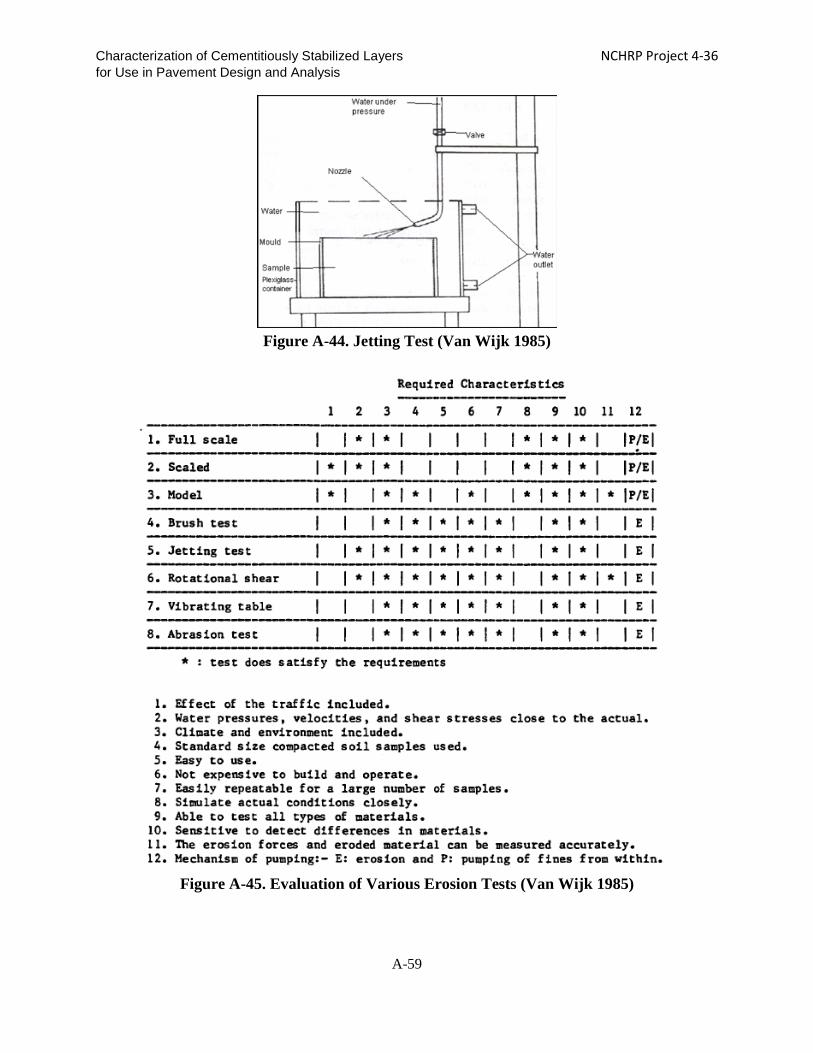
Characterization of Cementitiously Stabilized Layers NCHRP Project 4-36 for Use in Pavement Design and Analysis
Figure A-44. Jetting Test (Van Wijk 1985)
Figure A-45. Evaluation of Various Erosion Tests (Van Wijk 1985)
A-59

Characterization of Cementitiously Stabilized Layers NCHRP Project 4-36 for Use in Pavement Design and Analysis
The cyclic impact erosion (CIE) test has been used by other researchers to study the erosion of CSM (Sha and Hu 2002). This test consists of applying a cyclic load through a loading plate on a specimen submerged in water. The loading squeezes the water in and out during loading and unloading. The process creates erosion (Figure A-46) and simulates the erosion under the surface layer in a pavement that results from both the load impact caused by traffic and water movement.
(a) Loading (b) Unloading
Figure A-46. Flow of Water during Loading and Unloading Phases
Fatigue Tests
In the MEPDG, the fatigue behavior in the flexible pavement design of CSL is considered only for flexible pavements, not rigid pavements. When different stress levels are applied in the fatigue tests, a relationship between fatigue life and stress ratio can be developed for the fatigue model development.
Flexural Fatigue Test
The Australian flexural beam fatigue test method and AASHTO T321, Determining the
Fatigue Life of Compacted Hot-Mix Asphalt (HMA) Subjected to Repeated Flexural Bending, are two available tests methods. Sobhan and Das (2007) used prismatic beam specimens with dimensions of 30 in. × 6 in. × 6 in. for the flexural fatigue tests. Beams were prepared by compacting the mix in detachable steel molds in three equal layers at a target unit weight. Each layer was scarified for proper bonding with the next layer. The beams were sealed and cured for 24 hours in the laboratory environment, and then were de-molded and carried to the 100% RH room for curing. The average curing period was 28 days. Beams were tested in bending under a third-point loading configuration over a span length of 27 inches. In a typical fatigue experiment, the repeated load is usually expressed in terms of a stress ratio, defined as applied tensile stress at the bottom of a beam over the MOR.
A-60

Characterization of Cementitiously Stabilized Layers NCHRP Project 4-36 for Use in Pavement Design and Analysis
Large-Scale Model Experiment
Fatigue testing also can be conducted using the Large-Scale Model Experiment (LSME). The LSME is a prototype pavement structure testing system, which is constructed with the same materials employed in the field or in small-scale specimen tests (Kootstra et al. 2010, Benson et al. 2009). The pavement structure is instrumented to monitor stress and deformations, and is loaded cyclically using a plate load that simulates the wheel load. The boundary conditions and the applied cyclic loading are chosen carefully to replicate field conditions. The material being evaluated (in this case, CSL) is placed and tested (in different thicknesses if desired) covering the likely ranges that would be expected in actual field applications, or under the same conditions applied in a field test. The LSME requires large-scale mixing operations similar to those encountered in field construction and thus provides a realistic simulation of the fatigue of CSL. Figure A-47 shows the LSME setup.
Figure A-47. LSME Setup
Shrinkage Tests Free Drying Shrinkage Test
AASHTO T160, Length Change of Hardened Hydraulic Cement, can be modified to
characterize the drying shrinkage of CSM. Different RH values can be used to obtain the drying shrinkage strain. Long-term curing also is needed to measure the ultimate drying shrinkage strain.
A-61

Characterization of Cementitiously Stabilized Layers NCHRP Project 4-36 for Use in Pavement Design and Analysis
Tex-107-E also allows users to determine the bar linear shrinkage of soils and is used for CSM (Si 2008, Guthrie et al. 2001).
Chakrabarti and Kodikara (2003) conducted drying shrinkage tests according to methods found in AS1012.13-1992. A known quantity of stabilized mix according to standard maximum dry unit weight was compacted in two layers into a rectangular steel mold measuring 3 in. × 3 in. × 11 in (lo). A standard Proctor hammer with a maximum cross-sectional dimension of 2 inches (2.6 in., including the guide) was used to compact the material. Two gauge studs were placed at the middle of the end sections during compaction to facilitate shrinkage measurements. Specimens in duplicate per set were cured for 24 hours at 90% RH or above and at an air temperature of 70°F to 75°F. Subsequently, the specimens were dried in a controlled environment with 50% RH and at an air temperature of 71.6°F. Specimen lengths, li (in.), were recorded at gradually increasing intervals for up to 90 days while the specimens were kept in a controlled environment of 71.6°F and 50% RH. Shrinkage (εsh) at any time in microstrain can be determined as follows:
εsh = (lo – li) × 106/lo Eq. (A-23)
Figure A-48 shows a free drying shrinkage test setup. The unrestrained or free shrinkage represents the full shrinkage potential of a geomaterial under a given environmental condition. In free drying shrinkage, no shrinkage stress is generated.
Figure A-48. Free Drying Shrinkage Test
Restrained Shrinkage Test
Tensile stress is generated when the changes of moisture or temperature cause a CSL to
contract, and the underlying friction or self-restraint keeps the base from contracting. Shrinkage cracking occurs when the tensile stress exceeds the tensile strength of the cement-treated pavement layer (Cauley and Kennedy 1972). Because the restraint is in place either externally by the subgrade/surface layer or internally by differential shrinkage within different depths of the
A-62

Characterization of Cementitiously Stabilized Layers NCHRP Project 4-36 for Use in Pavement Design and Analysis
CSL due to the presence of humidity and temperature gradients in actual field conditions, the shrinkage cracking potential of each material in the CSL can be examined by restrained shrinkage testing.
In the concrete shrinkage cracking test, a ring of concrete is fabricated outside a steel ring. The internal steel ring hinders free drying and generates cracks. The onset of cracking and the development of the crack width are measured (Kodikara and Chakrabarti 2001).
The PCA recommends a drying shrinkage test on soil-cement beams restrained with a rough surface at their base (George 2002). This recommended procedure can be modified as a restrained shrinkage test for CSL. However, the bond condition recommended by the PCA, i.e., CSL on sand, does not generate shrinkage cracking within this 12-inch long beam. A typical shrinkage cracking spacing in the field is between 3 ft. and 60 ft. To generate shrinkage cracking in a laboratory-scale specimen, a strong bond must be created between the specimen and base. In addition, the length of the specimen must be increased.
Weiss et al. (1998) conducted restrained concrete slab tests to generate shrinkage cracking in a 39-inch long slab. The slab was fixed to the base, or to both ends and base, as shown in Figure A-49. By restraining the movement of the slab, the shrinkage cracking spacing is significantly shorter than the field cracking spacing. The concrete slab was bonded to a steel tube to prevent curling.
Figure A-49. Restrained Slab at Base and Ends (Weiss et al. 1998)
Thermal Shrinkage Test
The coefficient of thermal expansion (COTE) is important for thermal strain
determination, which is a key parameter in the shrinkage cracking model. AASHTO TP60, Standard Method of Test for Coefficient of Thermal Expansion of Hydraulic Cement Concrete, is a test method to determine the COTE of concrete. This method determines the COTE of a cylindrical concrete specimen, maintained in a saturated condition, by measuring the length change of the specimen due to a specified temperature change, as shown in Figure A-50. The
Restrained Slab at ends and base
A-63

Characterization of Cementitiously Stabilized Layers NCHRP Project 4-36 for Use in Pavement Design and Analysis
measured length change is corrected for any change in length of the measuring apparatus (previously determined), and the COTE is then calculated by dividing the corrected strain by the temperature change between 50°F and 122°F.
Cusson and Hoogeveen (2006) also recommend a test method for measuring the COTE, especially for early-age concrete. In their test, a concrete beam specimen is subjected to temperature cycles between 77°F and 86°F, including a 15-min temperature ramp followed by a 4-hour constant temperature. The cyclic strain, which does not include the permanent autogenous shrinkage strain, is used to determine the COTE.
Figure A-50. Test Setup of Coefficient of Thermal Expansion (Naik et al. 2006)
A-64

Characterization of Cementitiously Stabilized Layers NCHRP Project 4-36 for Use in Pavement Design and Analysis
REFERENCES
ACI. Guide for Modeling and Calculating Shrinkage and Creep in Hardened Concrete. ACI 209.2R-08.
Applied Research Associates, Inc. 2004. Guide for Mechanistic-Empirical Design for New and Rehabilitated Pavement Structures. NCHRP 1-37A Final Report, National Cooperative Highway Research Program, Transportation Research Board, National Research Council (March).
Arora, S. and A. H. Aydilek. 2005. Class F Fly-Ash-Amended Soils as Highway Base Material. Journal of Materials in Civil Engineering 17 (6) (November): 640-649.
Ashtiani, R. S., D. N. Little, E. Masad. 2007. Evaluation of the Impact of Fines on the Performance of Lightly Cement-Stabilized Aggregate Systems. Journal of the Transportation Research Board 2026: 81–88.
Atkinson, D. J. 1990. Evaluation of Rehabilitation Measures for Cracked Cement Treated Pavements. Main Road Department 6, Queensland, Australia.
Austroads. 2008. Guide to Pavement Technology: Part 2: Pavement Structural Design.
Barbu, B. 2004. Identification and Stabilization of Problematic Silts. Ph.D. dissertation, University of New Orleans.
Barnes, C. 2008. Structural Evaluation of the Point Michaud Road Pavement Rehabilitation Using Full-Depth Reclamation with Portland Cement. 7 (April).
Barstis, W. F. and A. B. Crawley. 2000. The Use of Fly Ash in Highway Construction U.S. 84/98 Adams County. Final Report No. 84-DP59-MS-05, Federal Highway Administration (May).
Beckham, T. and T. Hopkins. 2005. Swelling Pavement_ KY 499 Estill County. Research Report No. KTC-05-01/SPR 270-03-1I, Kentucky Transportation Center (March).
Benson, C. H., T. B. Edil, A. Ebrahimi, R. B. Kootstra, L. Li, and P. Bloom. 2009. Use of Fly Ash for Reconstruction of Bituminous Roads: Large Scale Model Experiments. Minnesota Department of Transportation, St Paul, MN,. (http://www.recycledmaterials.org/ Research/current/ project_47/project_47_final_report.pdf)
Bhattacharja, S. and J. Bhatty. 2003. Comparative Performance of Portland Cement and Lime in Stabilization of Moderate to High Plasticity Clay Soils. RD125, Portland Cement Association, Skokie, Illinois, USA, 26 pages,.
Bonnot, J. 1991. Semi-rigid Pavements. Association Internationale Permanente des Congrès de la Route.
Camargo F. F., T. B. Edil, and C. H. Benson. 2009. Strength and Stiffness of Recycled Base Materials Blended with Fly Ash. TRB 2009 Annual Meeting CD-ROM.
A-65

Characterization of Cementitiously Stabilized Layers NCHRP Project 4-36 for Use in Pavement Design and Analysis
Carteret, R. D., H. Chen, L. Comport, D. Firth, and A. Howard. 2009. Cost-Effective Structural Treatments for Rural Highways--Cemented Materials. Interim Report, Austroads Project No: TT1359 (June).
Cauley, R. P. and T. W. Kennedy. 1972. Improved Tensile Strength for Cement-Treated Bases and Subbases. Research Report No. 98-11, The Texas Highway Department (August).
Celaya, M., M. Veisi, S. Nazarian, and A. J. Puppala. 2009. Accelerated Moisture-Conditioning Process for Lime-Stabilized Clays. Transportation Research Board 88th Annual Meeting.
Chakrabarti, S. and J. Kodikara. 2003. Basaltic Crushed Rock Stabilized with Cementitious Additives-Compressive Strength and Stiffness, Drying Shrinkage, and Capillary Flow Characteristics. Eighth International Conference on Low-Volume Roads: 18-26.
Chakrabarti, S. and J. Kodikara. 2007. Direct Tensile Failure of Cementitiously Stabilized Crushed Rock Materials. Can. Geotech. J. 44: 231–240.
Chen, D. 2007. Field and Lab Investigations of Prematurely Cracking Pavements. Journal of Performance of Constructed Facilities (July/August): 293-301.
Chen, D., P. Harris, T. Scullion, and J. Bilyeu. 2005. Forensic Investigation of a Sulfate-Heaved Project in Texas. Journal of Performance of Constructed Facilities (November): 324-330.
Cho, Y., K. Lee, and S. Ryu. 2006. A Development of Cement-Treated Base Material for Reducing Shrinkage Cracks. Journal of the Transportation Research Board 1952: 134-143.
Corp of Engineers. 1994. Soil Stabilization for Pavement. Department of the Army, the Navy, and the Air force.
Cusson, D. and T. J. Hoogeveen. 2006. Measuring Early-Age Coefficient of Thermal Expansion in High-Performance Concrete. International RILEM Conference on Volume Changes of Hardening Concrete: Testing and Mitigation, Lyngby, Denmark (August 20).
Dallas, N., D. N. Little, and F. A. M. Shafee Yusuf. Example Problem Illustrating The Application of The National Lime Association Mixture Design and Testing Protocol (MDTP) to Ascertain Engineering Properties of Lime-Treated Subgrades for Mechanistic Pavement Design/Analysis: 29 pages (http://www.lime.org/AMDTP.pdf).
De Beer, M. 1990. Aspects of the Design and Behaviour of Road Structures Incorporating Lightly Cementitious Layers. Ph.D. dissertation, Faculty of Engineering, University of Pretoria, Pretoria (February).
De Beer, M. 1985. Behaviour of Cementitious Subbase Layers in Bitumen Base Road Structures. Masters dissertation, Faculty of Engineering, University of Pretoria, Pretoria.
De Beer, M. 1994. Field Behavior and Modeling of Cracked-and-Seated Semirigid Pavement
A-66

Characterization of Cementitiously Stabilized Layers NCHRP Project 4-36 for Use in Pavement Design and Analysis
after Rehabilitation. Transportation Research Record 1448: 83-91.
Dempsey, B. J. and M. R. Thompson. 1973. Vacuum Saturation Method for Predicting Freeze-thaw Durability of Stabilized Materials. Highway Research Board 442, Washington, D.C.
Dempsey, B. J., D. Janssen, J. Thomas, P. Frey, A. Ioannides, and R. Elliott. 1984. Development of a Preliminary ALRS Stabilized Material Pavement Analysis System (SPAS). Final Report, Engineering and Services Laboratory, Air Force Engineering and Services Center.
Departments of the Army and the Air Force. 1994. Pavement Design for Roads, Streets, and Open Storage Areas, Elastic Layered Method. Army TM 5-822-13/Air Force AFJMAN 32-1018 (October).
Esmer 1969. Freeze-Thaw Durability of Lime-Stabilized Clay Soils.
Esser, G., T. Chylik, R. Pesho, V. Ganesan, and D. N. Little. 2006. Assessment of In Situ Quality and Durability of Cement and Lime Stabilized Subgrade Soils in Northern Ohio, USA. TRB 2006 Annual Meeting CD-ROM.
Foley, G. 2002. Mix Design for Stabilised Pavement Materials (AP-T16). Austroads.
Fratta D., K. A. Alshibli, W. M. Tanner, L. Roussel. 2005. Combined TDR And P-Wave Velocity Measurements For The Determination of In Situ Soil Density. Geotechnical Testing Journal 28(6): 553-563.
Freeman, T. and D. Little. 2002. Maintenance Strategies for Pavements with Chemically Stabilized Layers. Research Report No. FHWA/TX-01/1722-6, Texas Department of Transportation (March).
Gass, B., DFC. Ventura, M. De Beer. 1993. Erodibility of Cemented Materials. Report No. RR 91/167, South African Roads Board (March).
Geiger, A., D. Yuan, S. Nazarian, and I. Abdallah. 2007. Effects of Pulverization of Properties of Stabilized Bases. Research Report 0-5223-1, Texas Department of Transportation (March).
George, K. P. 1990. Characterization and Structural Design of Cement-Treated Base. Transportation Research Record 1288: 78-87.
George, K. P. 1968. Cracking In Cement-Treated Bases and Means for Minimizing It. Highway Research Record 255: 59-71.
George, K. P. 2002. Minimizing Cracking in Cement-treated Materials for Improved Performance. Portland Cement Association.
George, K. P. 2001. Soil Stabilization Field Trial--Interim Report. Interim Report No. FHWA/MS-DOT-RD-03-133, Mississippi Department of Transportation.
Gnanendran, C. T. and J. Piratheepan. 2008. Characterisation of a Lightly Stabilised Granular Material by Indirect Diametrical Tensile Testing. International Journal of Pavement
A-67

Characterization of Cementitiously Stabilized Layers NCHRP Project 4-36 for Use in Pavement Design and Analysis
Engineering 9 (6): 445-456.
Grogan, W. P., C. A. Weiss, and R. S. Rollings. 1999. Stabilized Base Courses for Advanced Pavement Design--Report 1--Literature Review and Field Performance Data. Final Report to Project DOT/FAA/AR-97/65, Office of Aviation Research (September).
Guthrie, W. S., M. B. Roper, and D. L. Eggett. 2008. Evaluation of Laboratory Durability Tests for Stabilized Aggregate Base Materials. TRB 2008 Annual Meeting CD-ROM.
Guthrie, W. S., P. E. Ellis, and T. Scullion. 2001. Repeatability and Reliability of the Tube Suction Test. Transportation Research Board 80th Annual Meeting.
Guthrie, W. S., S. Sebesta, and T. Scullion. 2001. Selecting Optimum Cement Contents For Stabilizing Aggregate Base Materials. Report 7-4920-2, Project 7-4920, Project Title: Improving Long-Term Flexible Pavement Performance, Performed in Cooperation with the Texas Department of Transportation and the Federal Highway Administration, 64 pages (September).
Hadley, W. O., W. R. Hudson, and T. W. Kennedy. 1972. A Comprehensive Structural Design for Stabilized Pavement Layers. Research Report No. 98-13, The Texas Highway Department (August).
Hall, K. and J. Crovetti. 2007. Performance of Drained and Undrained Rigid Pavements in the LTPP SPS-2 Experiment. TRB 2007 Annual Meeting CD-ROM.
Harris, J. P., S. L. Hilbrich, S. Sebesta, and T. Scullion. 2007. Stabilization of a High Sulfate Soil Project in Eagle Pass, Texas. Transportation Research Board 86th Annual Meeting.
Hilbrich, S. L. and T. Scullion. 2007. Rapid Alternative for Laboratory Determination of Resilient Modulus Input Values on Stabilized Materials for AASHTO Mechanistic-Empirical Design Guide. Journal of the Transportation Research Board. 2026: 63-69.
Howard, M. D. 1988. Erosion of Cement Treated Pavements. 14th ARRB Conference, Canberra, Australian Capital Territory 7 (28 August-2 September): 202-211.
Hudson, W. R. and T. W. Kennedy. 1968. An Indirect Tensile Test for Stabilized Materials. Research Report No. 98-1, The Texas Highway Department (January).
Indraratna, B., T. Muttuvel, H. Khabbaz, R. Armstrong. 2008. Predicting the Erosion Rate of Chemically Treated Soil Using a Process Simulation Apparatus for Internal Crack Erosion. Journal of Geotechnical and Geoenvironmental Engineering. 134 (6) (June): 837-844.
Jameson, G. W., K. G. Sharp, and R. Yeo. 1992. The Fatigue Performance of Asphalt and Cement-Treated Crushed Rock under Accelerated Loadings.
Jayawickrama, P. W., W. K. Wray, R. C. Seal, and N. E. Wright. 1998. Experimental Pavement Reconstruction Project to Determine Long-Term Effectiveness of Lime and Cement for Stabilization of Pavement Subgrade Soils. Report No. TX-7-2967-F, Texas Department of Transportation (September).
A-68

Characterization of Cementitiously Stabilized Layers NCHRP Project 4-36 for Use in Pavement Design and Analysis
Jung, Y., D. G. Zollinger, M. Won, and A. J. Wimsatt. 2009. Subbase and Subgrade Performance Investigation for Concrete Pavement. Technical Report (Texas Transportation Institute), 6037-1.
Kennedy, T.W. and W. R. Hudson. 1973. Tensile Properties of Subbases for Use in Rigid Pavement Design. Report No. CFHR 3-8-66-98-14F, Texas Highway Department (Februrary).
Khoury, N. and M. M. Zaman. 2007. Durability of Stabilized Base Courses Subjected to Wet–Dry Cycles. International Journal of Pavement Engineering. 8 (4) (December): 265–276.
Khoury, N. N. 2005. Durability of Cementitiously Stabilized Aggregate Bases for Pavement Application. Ph.D. dissertation, The University of Oklahoma.
Kodikara, J. and S. Chakrabarti. 2001. Shrinkage Behaviour of Cemented Materials as Applicable to Insitu Pavement Stabilisation.
Kootstra, B. R., A. Ebrahimi, T. B. Edil, and C. H. Benson. 2010. Plastic Deformation of Recycled Base Materials. GeoFlorida’2010, ASCE Geo Institute, CD‐ROM.
Kumar, P., P. K. Mehta, and P. J. M. Monteiro. 2006. Concrete: Microstructure, Properties, and Materials. McGraw-Hill, Third Edition, 684 pages
Leonard, J. and G. Richard. 2004. Estimation of Runoff Critical Shear Stress for Soil Erosion from Soil Shear Strength. Catena 57: 233–249.
Li, Y., J. B. Metcalf, S. A. Romanoschi, and M. Rasoulian. 1999. Performance and Failure Modes of Louisiana Asphalt Pavements with Soil-Cement Bases under Full-Scale Accelerated Loading. Transportation Research Record 1673: 9-15.
Li, Y., S. Mao, and Q. Sha. 1992. The Performance of Pavement with Semi-Rigid Base under Accelerated Loading – the Zhengding and Zhouzho (China) ALF Trials 1990/91. Pavement Performance and Materials 2: 191-204.
Lim, S. and D. G. Zollinger. 2003. Estimation of the Compressive Strength and Modulus of Elasticity of Cement-Treated Aggregate Base Materials. Transportation Research Record 1837: 30-38.
Ling, J., H. Xie, and R. Guo. 2008. A Method to Predict Resilient Modulus of Lime and Lime-Cement Stabilized Soils Used in Highway Subgrade. Transportation Research Board 87th Annual Meeting.
Little, D. N. and S. Nair. 2007. Sensitivity of Selected Colorado Soils to Form Ettringite/Thaumasite when Treated with Calcium-Based Stabilizers and when Soluble Sulfates are Available. Final Report to CDOT-2007-14, Texas Transportation Institute.
Little, D. N. 1995. Handbook for Stabilization of Pavement Subgrades and Base Courses with Lime. Kendal/Hunt Publishing Company.
Little, D. N. 1999. Evaluation of Structural Properties of Lime Stabilized Soils and Aggregates
A-69

Characterization of Cementitiously Stabilized Layers NCHRP Project 4-36 for Use in Pavement Design and Analysis
- Volume 1 Summary of Findings. The National Lime Association (January 5).
Little, D. N., T. Scullion, P. B. V. S. Kota, and J. Bhuiyan. 1995. Guidelines for Mixture Design and Thickness Design for Stabilised Bases and Subgrades. Final Report to FHWA/TX-95/1287-3F, Texas Transportation Institute (October).
Luo, R. and J. A. Prozzi. 2008. Benefit of Lime Treatment for Controlling Longitudinal Pavement Cracking Due to Expansive Subgrade. TRB 2008 Annual Meeting CD-ROM.
Luo, R. and J. A. Prozzi. 2008. Development of Longitudinal Cracks on Pavement over Shrinking Expansive Subgrade. TRB 2008 Annual Meeting CD-ROM.
Mallela, J., J. Hall, and K. Smith. 2007. Role of Stabilized and Drainable Bases in Early-Age Cracking on Concrete Airfield Pavements. Journal of the Transportation Research Board 2004: 150–162.
Marais, C. P., E. Otte, and L. A. Bloy. 1973. The Effect of Grading on Lean-Mix Concrete. Highway Research Record 441: 86-96.
Meng, S., L. Hu, D. Wei, and Y. Li. 2004. The Performance of Stabilized Base Pavements under Accelerated Loading. In the Proceedings of 2004 Accelerated Pavement Testing International Conference, Minneapolis, MN.
Metcalf, J. B., F. L. Robert, M. Rasoulian, S. Romanoschi, Y. Li, and L. Djakfar. 2001. Construction and Comparison of Louisiana’s Conventional and Alternative Base Courses Under Accelerated Loading. Final Report to Research Project No. 98-3ALF & Research Project No. 98-2ALF, Louisiana Department of Transportation and Development (November).
Midgley, L. and R. Yeo. 2008. The Development and Evaluation of Protocols for the Laboratory Characterisation of Cemented Materials. Austroads Publication No. AP–T101/08, 89.
Miller, H. J., W. S. Guthrie, M. Kestler, and C. Carbo. 2006. Cement Treatment of Frost-Susceptible New England Base Materials Blended with Reclaimed Asphalt Pavement. ASCE Proceedings of 13th International Conference on Cold Regions Engineering, Orono, Maine, USA, Paper No. 58, July 23–26.
Naik, T. R., Y. Chun, R. N. Kraus. 2006. Investigation of Concrete Properties to Support Implementation of the new AASHTO Pavement Design Guide (Completed). Final Report to 0092-06-03, Wisconsin Department of Transportation (November).
Naji, K. N. and M. M. Zaman. 2005. Flexural Properties of Stabilized-Aggregate Beams Subjected to Freeze-Thaw Cycles. TRB 2005 Annual Meeting CD-ROM.
Neal, B. F. and J. H. Woodstrom. 1977. Faulting of Portland Cement Concrete Pavements. Report to FHWA-CA-TL-5167-77-20, California Department of Transportation (July).
Ni, F., Q. Li, X. Gu, and Z. Li. 2008. Prediction Model for Shrinkage Cracking Spacing of
A-70

Characterization of Cementitiously Stabilized Layers NCHRP Project 4-36 for Use in Pavement Design and Analysis
Cement Stabilized Base. TRB 2008 Annual Meeting CD-ROM.
Norling, L. T. 1973. Minimizing Reflective Cracks in Soil-Cement Pavements: A Status Report of Laboratory Studies and Field Practices. Highway Research Record 442: 22-33.
Norling, L. T. 1963. Standard Laboratory Tests for Soil-Cement - Development, Purpose and History of Use. Highway Research Record 36: 1-10.
Nussbaum, P. J. and L. D. Childs. 1975. Repetitive Load Tests of Concrete Slabs on Cement-Treated Subbases. Portland Cement Association.
Otte, E. 1978. A Structural Design Procedure for Cement-Treated Layers In Pavements. Ph.D. dissertation, Faculty of Engineering, University of Pretoria.
Paige-Green, P. 1998. Recent Developments in Soil Stabilization. Proceedings of the Conference of the Australian Road Research Board: 121-135.
Petry, T. and C. Jiang. 2007. Soil Suction and Behavior of Chemically Treated Clays. Journal of the Transportation Research Board 2026: 30–38.
Portland Cement Association. 1975. Thickness Design of Soil-Cement Pavements for Heavy Industrial Vehicles.
Portland Cement Association. 1992. Soil-Cement Laboratory Handbook.
Pretorius, P. C., Bruinette, Kruger, Stoffberg, Hugo, and C. L. Monismith. 1972. Fatigue Crack Formation and Propagation in Pavements Containing Soil-cement Bases. Highway Research Record 407: 102-150.
Pretorius, P.C., and C. L. Monismith. 1971. Prediction of Shrinkage Stresses in Pavements Containing Soil-Cement Bases. Highway Research Record 362: 63-86.
Raad, L., C. L. Monismith, and J. K. Mitchell. 1977. Tensile Strength Determinations for Cement-Treated Materials. Transportation Research Board 641: 48-52.
Ramsey, W. J. and O. L. Lund. 1959. Experimental Lime Stabilization in Nebraska. Bureau of Public Roads, Hpr-1/6/: 63-104.
Ras, E. and A. T. Visser. 2004. The Development of A Rotational Shear Device for Evaluating Erodibility of Stabilised Subbases. Proceedings of the 23rd Southern African Transport Conference (12– 15 July): 90-99.
Richardson, D. N. 1996. AASHTO Layer Coefficients for Cement-Stabilized Soil Bases,” Journal of Materials in Civil Engineering (May): 83-87.
Romanoschi, S. A. and J. B. Metcalf. 2001. Effects of Interface Condition and Horizontal Wheel Loads on the Life of Flexible Pavement Structures. Transportation Research Board 1778: 123-131.
Ruiz, J. M., R. O. Rasmussen, G. P. Chang, J. C. Dick, and P. K. Nelson. 2005. Computer-Based Guidelines For Concrete Pavements Volume II—Design and Construction Guidelines and HIPERPAV II User’s Manual. Final Report No. FHWA-RD-04-121,
A-71

Characterization of Cementitiously Stabilized Layers NCHRP Project 4-36 for Use in Pavement Design and Analysis
Office of Infrastructure Research and Development, Federal Highway Administration (February).
Scullion, T. 2002. Field Investigation: Pre-Cracking of Soil-Cement Bases to Reduce Reflection Cracking. TRB 2002 Annual Meeting CD-ROM.
Scullion, T. and P. Harris. 1998. Forensic Evaluation of Three Failed Cement-Treated Base Pavements. Transportation Research Board 1611: 10-18.
Scullion, T., J. Uzan, S. Hilbrich, and P. Chen. 2008. Thickness Design Systems for Pavements Containing Soil-Cement Bases. PCA R&D SN2863.
Scullion, T., S. Guthrie, and S. Sebesta. 2003. Field Performance and Design Recommendations for Full Depth Recycling in Texas. Report No. FHWA/TX-03/4182-1, Texas Department of Transportation (March).
Scullion, T., S. Sebesta, J. P. Harris, and I. Syed. 2005. Evaluating the Performance of Soil-Cement and Cement-Modified Soil for Pavements: A Laboratory Investigation. Portland Cement Association.
Sebesta, S. 2005. Use of Microcracking to Reduce Shrinkage Cracking in Cement-Treated Bases. Journal of the Transportation Research Board 1936: 3–11.
Selezneva, O., J. Jiang, and S. D. Tayabji. 2000. Preliminary Evaluation and Analysis of LTPP Faulting Data. Final Report No. FHWA-RD-00-076 (September).
Sha, A. and L. Hu. 2002. Experimental Study on the Anti-erosion Properties of Pavement Base Materials. Chinese Journal of Geotechnical Engineering 24 (3).
Si, Z. and C. H. Herrera. 2007. Forensic Case Studies on Low-Volume Roads in Texas. Journal of the Transportation Research Board 1989: 327-335.
Si, Z. 2008. Forensic Investigation of Pavement Premature Failure due to Soil Sulfate-Induced Heave. Journal of Geotechnical and Geoenvironmental Engineering (August): 1201-1204.
Sobhan, K. and B. M. Das. 2007. Durability of Soil–Cements against Fatigue Fracture. Journal of Materials in Civil Engineering 19 (1) (January): 26-32.
Sobhan, K. and M. Mashnad. 2000. Fatigue Durability of Stabilized Recycled Aggregate Base Course Containing Fly Ash and Waste-Plastic Strip Reinforcement. Final Report, Recycled Materials Resource Center, University of New Hampshire (November).
Sobhan, K. and R. J. Krizek. 1998. Resilient Properties and Fatigue Damage in Stabilized Recycled Aggregate Base Course Material. Transportation Research Record 1611: 28-37.
Syed, I. M. and T. Scullion. 2001. Performance Evaluation of Recycled and Stabilized Bases in Texas. Transportation Research Record 1757:14-21.
Syed, I., T. Scullion, and R. B. Randolph. 2000. Tube Suction Test for Evaluating Aggregate Base Materials in Frost- and Moisture-Susceptible Environments. Transportation Research Record 1709: 78-90.
A-72

Characterization of Cementitiously Stabilized Layers NCHRP Project 4-36 for Use in Pavement Design and Analysis
Syed, I., T. Scullion, and R. E. Smith. 2003. Recent Developments in Characterizing Durability of Stabilized Materials. TRB 2003 Annual Meeting CD-ROM.
Theyse, H. L., M. De Beer, and F. C. Rust. 1996. Overview of South African Mechanistic Pavement Design Method. Transportation Research Record 1539: 6-17.
Theyse, H. L., M. De Beer, J. Prozzi, and C. J. Semmelink. 1995. TRH4 Revision Updating the Transfer Functions for the South.
Thogersen, F. and L. Bjulf. 2005. Mechanistic Design of Semi-rigid Pavement: An Incremental Approach. http://www.vejdirektoratet.dk/publikationer/VIrap138/index.htm
Thompson M. 1986. Mechanistic Design Concepts for Stabilized Base Pavements. University of Illinois.
Thompson, M. R. and B. J. Dempsey. 1977. Evaluation of Freeze-Thaw Durability of Stabilized Materials. Transportation Research Record 612: 62-70.
Thompson, M. R. 1970. Quantitative Characterization of Cyclic Freezing and Thawing in Stabilized Pavement Materials. Highway Research Record 30: 38-44.
TxDOT. 2005. Guideline for Treatment of Sulfate Rich Soils and Base in Pavement.
Van Blerk, P. G. and T. Scullion. 1995. Evaluation of Stabilized Base Durability Using a Modified South African Wheel Tracking Device. Research Report to TX-96/29/2919-1, Texas Department of Transporation.
Van Wijk, A. J. 1985. Rigid Pavement Pumping: (1) Subbase Erosion, (2) Economic Modeling. Information Report. Purdue and Indiana State Highway Commission JHRP (May 16).
Vasudev, D. 2007. Performance Studies on Rigid Pavement Sections Built on Stabilized Sulfate Soils. Master Thesis, University of Texas at Arlington (May).
Ventura, DFC. 2003. Durability Testing of LCB and CTB Materials Supplied by Caltrans. Technical Memorandum No. TM-UC-PRC-2003-2, California Department of Transportation (May).
Von Quintus, H. L., J. Mallela, and J. Jiang. 2005. Expected Service Life and Performance Characteristics of HMA Pavements in LTPP. Asphalt Pavement Alliance (February).
Vorobieff, G. 1997. Application of Research in Road Stabilisation. Application of Research in Road Stabilisation (June).
Wang, M. and M. T. Huston. 1972. Direct-Tensile Stress and Strain of a Cement-Stabilized Soil. Highway Research Record 379, Cement-stabilized Soil, Highway Research Board.
Weiss, W. J., W. Yang, and S. P. Shah. 1998. Shrinkage Cracking of Restrained Concrete Slabs. Journal of Engineering Mechanics124 (7) (July): 765-774.
Wen, H. and B. Ramme. 2008. A Performance Evaluation of Asphalt Pavement with Recycled Pavement Materials Treated by Self Cementing Fly Ash and Field Verification Using ME
A-73

Characterization of Cementitiously Stabilized Layers NCHRP Project 4-36 for Use in Pavement Design and Analysis
Design Guide: A Case Study. Paper presented at 2008 ASCE Pavement Conference, Bellevue, WA (October).
Wesevich, J., B. F. McCullough, and N. H. Burns. 1987. Stabilized Subbase Friction Study for Concrete Pavements. Research Report University of Texas at Austin. Center for Transportation Research, No. 459-1.
Whitehurst, E. A. and E. J. Yoder. 1952. Durability Tests on Lime-Stabilized Soils. Highway Research Board Proceedings 31: 529-540.
Wimsatt, A. J., B. F. McCullough, and N. H. Burns. 1987. Methods of Analyzing and Factors Influencing Frictional Effects of Subbases. Research Report University of Texas at Austin. Center for Transportation Research, No. 459-2F.
Wise, J. and W. R. Hudson. 1971. An Examination of Expansive Clay Problem in Texas.
Wjvdm, S., E. Sadzik, and C. J. Semmelink. 2001. Conceptual Performance Model for Deep In Situ Recycled Pavements with Cement and Bitumen Additives. 1st International Symposium on Subgrade Stabilisation and In Situ Pavement Recycling Using Cement, Salamanca, Spain (1-4 October): 1-13.
Yeo, R., B. Vuong, and A. Alderson. 2002. Towards National Test Methods for Stiffness and Fatigue Characterisation of Stabilised Materials. Report RC2028- 002 for Austroads (July): 26 pages.
Yeo, Y. 2008. Fatigue Performance of Cemented Materials under Accelerated Loading –Influence of Vertical Loading on the Performance of Unbound and Cemented Materials. Austroads (August).
Yesiller N., J. L. Hanson, A. T. Rener, and M. A. Usmen. 2001. Ultrasonic Testing for Evaluation of Stabilized Mixtures. Transportation Research Record 1757: 32–39.
Yue, F. and C.Yang. 2004. Semi-Rigid Asphalt Pavement Thermal Reflective Crack in Finite Element Method. Journal of Guilin Institute of Technology 24 (1) (January): 52-54.
Zaman, M. M., J. Zhu, and J. G. Laguros. 1999. Durability Effects on Resilient Moduli of Stabilized Aggregate Base. Transportation Research Record 1687: 30-38.
Zhang, Z. and M. Tao. 2006. Stability of Calcium Sulfate Base Course in a Wet Environment. Final Report to FHWA/LA.06/419, Louisiana Transportation Research Center (July).
Zube, E., C. G. Gates, E. C. Shirley, and H. A. Munday. 1969. Service Performance of Cement treated Base as Used in Composite Pavements. Highway Research Record 291: 57-69.
A-74

Characterization of Cementitiously Stabilized Layers NCHRP Project 4-36 for Use in Pavement Design and Analysis
FINDINGS OF SURVEY AND REVIEW OF SPECIFICATIONS
1. Survey Results
2. Summary of State Agencies’ Specifications
A-75

Characterization of Cementitiously Stabilized Layers NCHRP Project 4-36 for Use in Pavement Design and Analysis
NCHRP Project 04-36 Characterization of Cementitiously Stabilized Layers for Use in
Pavement Design and Analysis
Results from Survey of State Highway Agencies
The research team distributed questionnaires to collect information about cementitiously stabilized layers from state highway agencies. In total, the team received 40 responses from state DOTs. The goal of the survey was to collect feedback from state DOTs regarding the characterization of cementitiously stabilized layers in pavements. The survey covers specifications for types of cementitious additives, the extent of their use, engineering parameters, pavement performance, quality control methods, and construction practices.
Statistics of the Results from Questionnaire The following 8 questions were listed in the questionnaire. The number of occurrences per
answer relative to the total responses is shown in parentheses or in graphs. 1) Does your agency use cementitiously stabilized materials for subgrade, subbase or base
of pavement construction?
[ 28 of 40-out of 40 responses, 28 states use it ] Yes; if so, what is the extent of use? Subgrade modification: (10 of 28 ) Little; ( 6 of 28 ) Moderate; ( 7 of 28 ) Extensive Subbase modification: (12 of 28 ) Little; ( 2 of 28 ) Moderate; ( 3 of 28 ) Extensive Base modification: (9 of 28 ) Little; ( 9 of 28 ) Moderate; ( 5 of 28 ) Extensive [ 12 of 40 ] No; if so, please provide details for non-usage (please use additional page as
needed and there is no need for providing input for the items below): Wyoming chooses “No” for Q1, but it still answers the other questions.
Summary: Most of the agencies (28 of 40) use cementitiously stabilized materials. Little
subgrade and subbase modifications are used, and most of stabilization focuses on base.
2) If Yes, what type of cementitious additives are used:
A-76

Characterization of Cementitiously Stabilized Layers NCHRP Project 4-36 for Use in Pavement Design and Analysis
Clay Silt Sand Gravel RAP Expansive
Soil Cement 9/28 19/28 17/28 14/28 5/28 4/28
Lime 18/28 4/28 1/28 2/28 11/28 Class C fly ash 3/28 7/28 5/28 4/28 5/28 2/28
Lime+Class F fly ash 2/28 2/28 1/28 1/28 1/28 1/28
Lime+cement 3/28 1/28 1/28 1/28 2/28 Cement kiln dust 2/28 2/28 1/28 2/28 1/28
Note:
Summary: Cement and lime are the two major additives. Cement is usually used to stabilize cohesionless soils, such as silt (19/28), sand (17/28), and gravel (14/28). Lime is applied to cohesive soils, such as clay and expansive soil. Other stabilizers include class C fly ash, a mixture of lime and class F fly ash, and cement kiln dust.
3) How are the cementitiously stabilized materials incorporated in your agency’s pavement
design? [ 18/27 ] Layer Coefficient [ 8/27 ] Modulus [ 8/27] Others
Summary: Most of the agencies use a layer coefficient (18/27) to incorporate cementitiously stabilized materials in pavement design, followed by the modulus (8/27). In addition, there are some other situations, a) Gravel Equivalent; b) when allowed; Mr (Mr<3000psi); c) no contribution; and d) soil support value or K value.
4) In your opinion, what are the important engineering parameters for cementitiously
stabilized materials that should be considered? Please place a rank order of importance with 1 being the most important.
[ ] Strength; Test Method: [ ] Stiffness; Test Method: [ ] Durability; Test Method: [ ] Erodibility; Test Method: [ ] Swelling; Test Method: [ ] Shrinkage; Test Method: [ ] Fatigue; Test Method: [ ] Others:
Summary: 28 states responded to this question. Strength (17 of rank 1), durability (8 of rank
2; 7 of rank 3) and stiffness (8 of rank 2; 4 of rank 3) are the three most significant engineering
A-77

Characterization of Cementitiously Stabilized Layers NCHRP Project 4-36 for Use in Pavement Design and Analysis
parameters for cementitiously stabilized materials. The agencies also consider erodibility, swelling, shrinkage, fatigue, and some other engineering parameters.
. 5) List the key performance issues for pavements with cementitiously stabilized layers
based on your experience and knowledge? Please place a rank order of importance with 1 being the most important for each type of pavement.
Asphalt Pavement: [ ] Transverse Cracking; Reasons: [ ] Longitudinal Cracking in Wheelpatch; Reasons: [ ] Longitudinal Cracking Outside Wheel path; Reasons: [ ] Alligator Cracking; Reasons: [ ] Block Cracking; Reasons: [ ] Others; Reasons:
Summary: For asphalt pavement, 23 states responded to this question. Transverse cracking
receives the most attention (13 of rank 1), followed by alligator cracking, longitudinal cracking in the wheel path, block cracking, and longitudinal cracking outside the wheel path.
Concrete Pavement: [ ] Transverse Cracking; Reasons: [ ] Others; Reasons:
Summary: For concrete pavements, 12 states answered this question. As for asphalt
pavement, transverse cracking is also the most crucial pavement issue. In addition, there are some other issues reported: faulting due to CTB erosion, large-area block cracking, improvements needed in uniformity, freeze and thaw and load transfer, joint spalling, base failure, and longitudinal cracking.
6) What is the field quality control method adopted by your agency? Check all apply.
[ 27/27 ] Density; Method & Specifications: [ 13/27 ] Moisture content; Method & Specifications: [ 10/27 ] Uniformity of mixing; Method & Specifications: [ 12/27 ] Strength; Method & Specifications: [ 5/27 ] Others; Method & Specifications:
Summary: The results indicate the importance of a field quality control method from high to
low density, moisture content, strength and uniformity of mixing. Other methods include uniform interval thickness, immediate bearing value, gradation, and deflection.
7) What are your agency’s construction practices for cementitious stabilization?
A-78

Characterization of Cementitiously Stabilized Layers NCHRP Project 4-36 for Use in Pavement Design and Analysis
Mixing: [ 27/27 ] In-situ Mixing [ 12/27 ] Plant Mixing Curing Method: [ 18/24 ] Asphalt emulsion; [ 14/24 ] Moisture;
[ 4/24 ] others: wax; plasting sheeting; contractor’s choice; cutback asphalt Construction Cut-off Date/temperature: ____________
Summary: For mixing, all agencies that responded to this question allow the use of in situ
mixing (27/27), and almost half of them (12/27) specify plant mixing. In general in situ mixing is applicable to lime as a stabilizer, whereas plant mixing, which could provide higher quality, is used when cement is the stabilizer.
With regard to curing method, 24 agencies responded. 18 of 24 agencies specify curing with
asphalt emulsion; 14 of 24 use a moisture curing method. Other curing methods are wax, plastic sheeting, cutback asphalt and contractor’s choice.
8) Did your agency conduct any field study/experiment in connection with cementitious
stabilization of pavement materials? [ 14/27 ] Yes; [ 13/27 ] No; If yes, please provide information for lab test results and field distress survey data, or
provide contacts for these studies/experiments? (Please see the “Survey Results”)
Summary: Out of 27 state DOTs, almost half of them (14/27) use field study/experiments; the others (13/27) do not. The information for lab tests or contacts are in the document “Survey Results.
A-79

Characterization of Cementitiously Stabilized Layers NCHRP Project 4-36 for Use in Pavement Design and Analysis
Complete Listing of Responses Received for the NCHRP 04-36 Survey
1 2 3 4 5 6 7 8
Extent of use Stabilized
materials
Pave
men
t de
sign
CSL Properties Ranking of performance of pavement (1-most important)
Field quality control Construction practices Field study/experiment
Stat
e
Subg
rade
Subb
ase
Bas
e
additives-soil Ranking (1-most important) Flexible Rigid Method
Mix
ing
Cur
ing
Cut
-off
D
ate
/ tem
p
Information or contact
Ala
bam
a
mod
erat
e
little
little
•cement-sand •lime-clay,
expansive soil laye
r coe
ff.
1-strength (lime stabilization
AASHTO T 208, soil-cement AASHTO T
22) 2-reduction in
Plasticity Index (lime stabilization,
AASHTO T 90)
1-transverse (reflective cracking and ride
quality)
1-transverse (ride quality, water
infiltration (potential pumping))
•density (AASHTO T 310)
•moisture content (lime, AASHTO T 265; soil-
cement, AASHTO T 134) •strength (lime,
AASHTO T 208; soil-cement, AASHTO T 22)
•in
-situ
-lim
e •
plan
t-soi
l-cem
ent
•asp
halt
•moi
stur
e lim
eno
t bet
wee
n O
ct. 1
and
Apr
. 1
•so
il-ce
men
t-air,
40F
; soi
l, 50
F No.
Ala
ska
little
•cement-gravel
mod
ulus
1-shrinkage 2-durability 3-stiffness 4-fatigue
1-alligator cracking (shringkage cracking)
2-block cracking (shringkage cracking)
density
in-s
itu
Ari
zona
no cementitious bases due to
cracking
A-80

Characterization of Cementitiously Stabilized Layers NCHRP Project 4-36 for Use in Pavement Design and Analysis
1 2 3 4 5 6 7 8
Extent of use
Stabilized materials
Pave
men
t de
sign
CSL Properties Ranking of performance of pavement (1-
most important) Field quality control Construction practices Field
study/experiment
Stat
e
Subg
rade
Subb
ase
Bas
e
additives-soil Ranking (1-most important)
Flexible Rigid Method
Mix
ing
Cur
ing
Cut
-off
D
ate
/ tem
p
Information or contact
Cal
iforn
ia
little
little
mod
erat
e
•cement-silt, sand, RAP, expansive soil
•lime-RAP •class C fly ash
RAP •lime+cement-expansive soil
•cement kiln dust-RAP
Gra
vel E
quiv
alen
t 1-strength(CT 312, CT 373 (ASTM C
977)) 2-stiffness
3-shrinkage 4-durability 5-swelling
*-transverse (reflective cracking)
*longitudinal outside (reflective cracking) *-block (shrinkage cracking in CTN)
*-others (faulting due to CTB
erosion)
•density(CT231,CT312) •moisture(CT226)
•uniformity (CT338(ASTM M 92))
•strength(CT 312, CT 373 (ASTM C 977))
•others(CT 217 (sand equivalent), CT 202 (AASHTO M 92))
•in-s
itu
•pla
nt
•asp
halt
•wax
40F
Pulverized Asphalt Concrete and FDR-Foamed Asphalt data at:
www.its.berkeley.edu/pavementrese
arch/ •Contact Dave
Jones: djjones@ucdavis.
edu
Col
orad
o
little
little
•cement-gravel •lime-clay,
expansive soil •class C fly ash -silt,
sand, gravel laye
r coe
ff.
1-strength 2-stiffness 3-swelling 4-durability 5-shrinkage
6-fatigue 7-erodibility
1-transverse 2-alligator
3-block 4-longitudinal in
5-longitudinal out
1-transverse
•density •moisture
•uniformity •strength
in-s
itu
moi
stur
e
Con
nect
icu
t
Soils provide excellent support.
A-81

Characterization of Cementitiously Stabilized Layers NCHRP Project 4-36 for Use in Pavement Design and Analysis
1 2 3 4 5 6 7 8
Extent of use
Stabilized materials
Pave
men
t de
sign
CSL Properties Ranking of performance of pavement (1-
most important) Field quality control Construction practices Field
study/experiment
Stat
e
Subg
rade
Subb
ase
Bas
e
additives-soil Ranking (1-most important)
Flexible Rigid Method
Mix
ing
Cur
ing
Cut
-off
D
ate
/ tem
p
Information or contact
Del
awar
e
mod
erat
e
•cement-silt, sand
laye
r coe
ff.
1-strength 2-stiffness
3-durability 4-fatigue
5-erodibility 6-swelling 7-shrinkage
1-transverse (reflective cracking) 2-alligator
3-longitudinal in 4-block 5-longitudinal
out
•density •moisture •strength in
-situ
asph
alt
Flor
ida
little
little
•cement-clay, silt, sand
•la
yer c
oeff
. •
whe
n al
low
ed
*-strength (Florida Test Method FM 5-
520)
*-transverse (reflective)
•density (In archived specification 270, Soil –
Cement Base) •in-s
itu
•pla
nt
•asp
halt
•moi
stur
e
7 da
ys
Yes
Geo
rgia
little
little
mod
erat
e
•cement-clay •lime-clay
Laye
r coe
ff. 1-strength (CBR,
Density) 2-stiffness (CBR)
3-durability
1-transverse (reflective joint cracking of a
composite pavement because of similar
appearance) 2-block cracking (same
to transverse)
*- Large area block cracking on
a high truck volume facility
had a detrimental effect with time.
•density (Theoretical density; % of theoretical) •strength (Core breaks;
300 psi) •Uniform interval
thickness (within one-half inch of design)
•in-s
itu
•pla
nt
Cut
back
asp
halt
40F Yes.
Dwane Lewis 404-694-6685
A-82
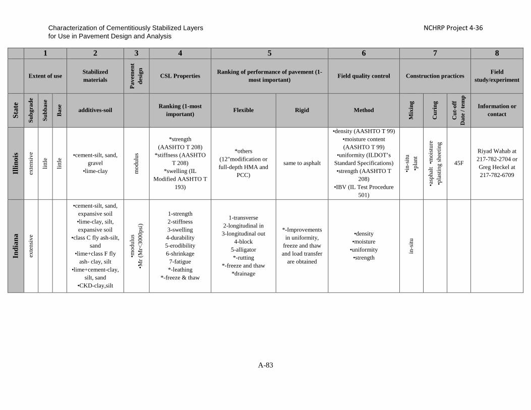
Characterization of Cementitiously Stabilized Layers NCHRP Project 4-36 for Use in Pavement Design and Analysis
1 2 3 4 5 6 7 8
Extent of use
Stabilized materials
Pave
men
t de
sign
CSL Properties Ranking of performance of pavement (1-
most important) Field quality control Construction practices Field
study/experiment
Stat
e
Subg
rade
Subb
ase
Bas
e
additives-soil Ranking (1-most important)
Flexible Rigid Method
Mix
ing
Cur
ing
Cut
-off
D
ate
/ tem
p
Information or contact
Illin
ois
exte
nsiv
e
little
little
•cement-silt, sand, gravel
•lime-clay mod
ulus
*strength
(AASHTO T 208) *stiffness (AASHTO
T 208) *swelling (IL
Modified AASHTO T 193)
*others (12"modification or full-depth HMA and
PCC)
same to asphalt
•density (AASHTO T 99) •moisture content (AASHTO T 99)
•uniformity (ILDOT’s Standard Specifications) •strength (AASHTO T
208) •IBV (IL Test Procedure
501)
•in-s
itu
•pla
nt
•asp
halt
•moi
stur
e •p
last
ing
shee
ting
45F
Riyad Wahab at 217-782-2704 or Greg Heckel at 217-782-6709
Indi
ana
exte
nsiv
e
•cement-silt, sand, expansive soil •lime-clay, silt, expansive soil
•class C fly ash-silt, sand
•lime+class F fly ash- clay, silt
•lime+cement-clay, silt, sand
•CKD-clay,silt
•mod
ulus
•M
r (M
r<30
00ps
i)
1-strength 2-stiffness 3-swelling 4-durability 5-erodibility 6-shrinkage
7-fatigue *-leathing
*-freeze & thaw
1-transverse 2-longitudinal in
3-longitudinal out 4-block
5-alligator *-rutting
*-freeze and thaw *drainage
*-Improvements in uniformity,
freeze and thaw and load transfer
are obtained
•density •moisture
•uniformity •strength
in-s
itu
A-83

Characterization of Cementitiously Stabilized Layers NCHRP Project 4-36 for Use in Pavement Design and Analysis
1 2 3 4 5 6 7 8
Extent of use
Stabilized materials
Pave
men
t de
sign
CSL Properties Ranking of performance of pavement (1-
most important) Field quality control Construction practices Field
study/experiment
Stat
e
Subg
rade
Subb
ase
Bas
e
additives-soil Ranking (1-most important)
Flexible Rigid Method
Mix
ing
Cur
ing
Cut
-off
D
ate
/ tem
p
Information or contact
Kan
sas
exte
nsiv
e
exte
nsiv
e
•cement-silt, sand •lime-clay,
expansive soil •class C fly ash-silt,
sand, RAP
Laye
r coe
ff.
1-swelling 2-shrinkage 3-durability
4-fatigue 5-erodibility 6-strength 7-stiffness
1-transeverse (thermal cracking)
2-alligator (Poor bond between HMA layers, insufficient structure) 3-longitudinal in (poor bond between HMA layers, insufficient
structure) 4-longitudinal out
(Construction joints)
1-joint spalling (inadequate air void system in concrete, also
durability factors due to poor
aggregates – “D”- cracking)
2-transverse (non-uniform subgrade or base support,
inadequate mixing of cementitiously
stabilized subgrades)
•density (Kansas Test Method KT-51, Nuclear
Gauge) •moisture content (Gas
Pressure Method, Kansas Test Method KT-11, or KT-51, Nuclear Gauge) •uniformity (Spec, test
application rate of material, gradation
requirements on mixed material
•in-s
itu
•pla
nt
•asp
halt
•moi
stur
e
40°F
or s
ubgr
ade
froz
en
Yes. Contact Greg Schieber, at
[email protected] or 785-296-1198
and will send reports
Ken
tuck
y
little
•cement-silt, sand •lime-clay
laye
r coe
ff.
1-strength (proof rool) 2-durability
(pavement life)
1-longitudinal in (truck loads)
•density (nuclear density machine)
•moisture (nuclear density machine)
•uniformity (field observation)
in-s
itu
asph
alt
Oct/ 40F
attachment
Mai
ne
little
little
mod
erat
e •cement-clay, silt, sand, gravel, RAP,
expansive soil
laye
r coe
ff.
1-stiffness 2-strength 3-fatigue
4-durability 5-shrinkage 6-swelling
7-erodibility
1-transverse (low temp)
2-longitudinal in (heavy truck) 3-longitudinal
out(bond)
•density (Nuclear
method–98% of test strip) in-s
itu
moi
stur
e
Sept.15/ 50F
Rick Bradbury, Maine DOT 207-
941-4597 richard.bradbury
@maine.gov
A-84

Characterization of Cementitiously Stabilized Layers NCHRP Project 4-36 for Use in Pavement Design and Analysis
1 2 3 4 5 6 7 8
Extent of use
Stabilized materials
Pave
men
t de
sign
CSL Properties Ranking of performance of pavement (1-
most important) Field quality control Construction practices Field
study/experiment
Stat
e
Subg
rade
Subb
ase
Bas
e
additives-soil Ranking (1-most important)
Flexible Rigid Method
Mix
ing
Cur
ing
Cut
-off
D
ate
/ tem
p
Information or contact
Mar
ylan
d
mod
erat
e
little
little
•cement-silt, sand, gravel
•lime-clay, silt
•laye
r coe
ff. (
base
or s
ubba
se)
•mod
ulus
(sub
grad
e)
(For all ASTM or AASHTO) 1-strength 2-stiffness
3-durability 4-fatigue
5-shrinkage 6-swelling
7-erodibility
1-transverse (reflective cracking)
no use cementitious
stabilized layers in concrete pavement
•density (MDSHA Standard Specifications)
•moisture (MDSHA Standard Specifications) •strength(Core Sampling → Unconf. Compressive
Testing, FWD)
in-s
itu
•asp
halt
•moi
stur
e 7 day cure
period
Mas
sach
use
tts just HMA
Min
neso
ta
No use due to cracking
A-85

Characterization of Cementitiously Stabilized Layers NCHRP Project 4-36 for Use in Pavement Design and Analysis
1 2 3 4 5 6 7 8
Extent of use
Stabilized materials
Pave
men
t de
sign
CSL Properties Ranking of performance of pavement (1-
most important) Field quality control Construction practices Field
study/experiment
Stat
e
Subg
rade
Subb
ase
Bas
e
additives-soil Ranking (1-most important)
Flexible Rigid Method
Mix
ing
Cur
ing
Cut
-off
D
ate
/ tem
p
Information or contact
Mon
tana
exte
nsiv
e
•cement-gravel, RAP
•class C fly ash-gravel, RAP
(typically use 3% portland cement and 2% class C fly ash,
for total of 5% cementitious
material.) Laye
r Coe
ffic
ient
0.2
0 in
/in
*-strength (unconfined
compression of standard Proctor
samples)
*-No performance issues have been
identified.
One portland cement concrete pavement failure (may have been
caused by erosion and/or durability
of the lean concrete base.)
•density (nuclear density, 96% of standard Proctor) •moisture content (+/-
optimum moisture from standard Proctor)
•strength (unconfined compression of proctor
sample, 400 psi minimum) •gradation
•in-s
itu
•pla
nt
•asp
halt
•35F
(gro
und)
•4
0F(a
ir)
No.
Neb
rask
a
exte
nsiv
e
exte
nsiv
e
exte
nsiv
e
•cement-silt •lime-clay,
expansive soil •class C fly ash-clay, silt, RAP
•CKD-clay
•laye
r coe
ff.
•mod
ulus
*-strength (compression)
*-stiffness (modulus)
•density (rolling) •moisture (mix design)
•uniformity (specs) in-s
itu
•asp
halt
•moi
stur
e
60F
Mick Syslo 402-479-4791 or
Nev
ada
mod
erat
e
mod
erat
e
mod
erat
e
•cement-clay, silt, RAP, expansive soil
•lime-clay, RAP, expansive soil
•lime+cement-clay, expansive soil
•laye
r coe
ff.
•mod
ulus
1-stiffness (ASTM D4609, D 6276)
2-durability(ASTM D560)
3-erodibility(ASTM D559)
4-strength(ASTM D1633)
1-transverse (reflective)
1-transverse (reflective)
2-base failure
•density (NEV. T101, T102, AND T103)
•moisture ( NEV. T236) •in-s
itu
•pla
nt
•asp
halt
•moi
stur
e
35F
A-86

Characterization of Cementitiously Stabilized Layers NCHRP Project 4-36 for Use in Pavement Design and Analysis
1 2 3 4 5 6 7 8
Extent of use
Stabilized materials
Pave
men
t de
sign
CSL Properties Ranking of performance of pavement (1-
most important) Field quality control Construction practices Field
study/experiment
Stat
e
Subg
rade
Subb
ase
Bas
e
additives-soil Ranking (1-most important)
Flexible Rigid Method
Mix
ing
Cur
ing
Cut
-off
D
ate
/ tem
p
Information or contact
New
H
amps
hire
NH DOT does not use
Cementitiously Stabilized
base materials
New
Je
rsey
no use
New
Mex
ico
mod
erat
e
mod
erat
e
mod
erat
e •cement-sand, gravel
•lime-clay, silt
laye
r coe
ff. (
base
d on
co
mpr
essi
ve st
reng
th)
1-stiffness 2-strength
3-durability 4-swelling 5-shrinkage 6-erodibility
•density •moisture
•uniformity in-s
itu
moi
stur
e
New
Yor
k
no use for cost
Nor
th D
akot
a
little
little
mod
erat
e
•cement-gravel •class C fly ash- expansive soil
•lime+class F fly ash- expansive soil la
yer c
oeff
.
1-strength 2-durability 3-swelling
1-thinner base section 2-alligator
3-block
•density •moisture •strength in
-situ
asph
alt
A-87

Characterization of Cementitiously Stabilized Layers NCHRP Project 4-36 for Use in Pavement Design and Analysis
1 2 3 4 5 6 7 8
Extent of use
Stabilized materials
Pave
men
t de
sign
CSL Properties Ranking of performance of pavement (1-
most important) Field quality control Construction practices Field
study/experiment
Stat
e
Subg
rade
Subb
ase
Bas
e
additives-soil Ranking (1-most important)
Flexible Rigid Method
Mix
ing
Cur
ing
Cut
-off
D
ate
/ tem
p
Information or contact
Ohi
o
mod
erat
e
•cement-clay, silt •lime-clay
in d
esig
n no
stiff
ness
, bu
t con
stru
ctab
ility
has
*-strength *-stiffness
*-durability *-erodibility
no issues in Ohio no issues in Ohio •density
•moisture in-s
itu
•asp
halt
•oth
ers
40F
http://www.dot.state.oh.us/Divisions/TransSysDev/Research/reportsandplans/Reports/2004/Pavements/14746-
FR.pdf
Okl
ahom
a
exte
nsiv
e
little
little
•cement-silt, sand, gravel
•lime-clay, expansive soil •class C fly ash- clay, silt, sand,
gravel •lime+class F fly
ash-clay •CKD-silt, sand,
gravel
•la
yer c
oeff
. •
mod
ulus
1-durability 2-stiffness 3-strength
4-erodibility 5-shrinkage
6-fatigue 7-swelling
•density (AASHTO T310)
•moisture content (AASHTO T310)
in si
tu
moi
stur
e
A-88

Characterization of Cementitiously Stabilized Layers NCHRP Project 4-36 for Use in Pavement Design and Analysis
1 2 3 4 5 6 7 8
Extent of use
Stabilized materials
Pave
men
t de
sign
CSL Properties Ranking of performance of pavement (1-
most important) Field quality control Construction practices Field
study/experiment
Stat
e
Subg
rade
Subb
ase
Bas
e
additives-soil Ranking (1-most important)
Flexible Rigid Method
Mix
ing
Cur
ing
Cut
-off
D
ate
/ tem
p
Information or contact
Ore
gon
little
little
•cement-clay, silt, gravel
•lime-clay, silt, expansive soil
non-
stru
ctur
al fo
r sub
grad
e, a
con
stru
ctio
n pl
atfo
rm
1-strength (Unconfined Compressive
Strength) 2-durability(Freeze-thaw performance)
1-block(reflective) 2-transverse(reflective) 3-longitudinal in (more
in HMA failure) 4-longitudinal out(reflective)
5-alligator(more in HMA failure)
1- ODOT uses CRCP –
longitudinal cracking has
occurred in CRCP over CTB, likely
due to a non-effective or non-
existent bond breaker
•density-ODOTSpec 00344&00330
•moisture-ODOTSpec 00344&00330
•uniformity-ODOTSpec 00344
•deflection-ODOT TM 158
in-s
itu
cont
ract
or's
choi
ce
Not
spec
ified
, mus
t mee
t com
pact
ion
/ de
flect
ion
Limited Dynamic Cone
Penetrometer (DCP) data
collection on Cement Modified
Subgrade (silt soil) in 2007 Contact is Rene’ Renteria, 503-
986-3122
Puer
to R
ico
not using cement treated bases,but lean concrete base
Rho
de
Isla
nd has very good
aggregate that is used for subgrades
A-89

Characterization of Cementitiously Stabilized Layers NCHRP Project 4-36 for Use in Pavement Design and Analysis
1 2 3 4 5 6 7 8
Extent of use
Stabilized materials
Pave
men
t de
sign
CSL Properties Ranking of performance of pavement (1-
most important) Field quality control Construction practices Field
study/experiment
Stat
e
Subg
rade
Subb
ase
Bas
e
additives-soil Ranking (1-most important)
Flexible Rigid Method
Mix
ing
Cur
ing
Cut
-off
D
ate
/ tem
p
Information or contact
Sout
h C
arol
ina
mod
erat
e
little
mod
erat
e
Cement-clay, silt, sand, gravel
•la
yer c
oeff
.
1-strength (SC-T-38) 2-shrinkage (No test) 3-durability (No test)
1-transverse (shrinkage from excess cement)
2-block cracking (shrinkage from excess
cement) 3-alligator (not in cement stabilized materials, but in
asphalt above cement stabilized layers)
•density (95% of AASHTO T-134 by the nuclear density gauge) •moisture content
(between optimum and optimum + 2 % by
Speedy Moisture gauge for soil materials, nuclear
density gauge for aggregate materials) •uniformity of mixing
(mixed to a homogeneous mixture by visual
inspection)
•in-s
itu (C
emen
t mod
ified
subg
rade
s and
re
cycl
ed b
ases
) •p
lant
(all
othe
r mat
eria
ls)
asph
alt
40 F
in sh
ade
and
risin
g
No. Contact Mike
Lockman, Geotechnical
Materials Engineer, (803)737-
6692, [email protected] if you
have any questions
Sout
h D
akot
a
little
•class C fly ash-silt, expansive soil
no c
emen
t tre
ated
m
ater
ial i
n de
sign
1-strength (initial strength)
Ten
ness
ee
little
little
•cement-clay, silt, sand
•lime-clay •lime+cement-
gravel laye
r coe
ff.
1-strength 2-stiffness
1-alligator (In compatability of
flexible pavement and stabilized material)
•density
•moisture •in-s
itu
•pla
nt
asph
alt
A-90

Characterization of Cementitiously Stabilized Layers NCHRP Project 4-36 for Use in Pavement Design and Analysis
1 2 3 4 5 6 7 8
Extent of use
Stabilized materials
Pave
men
t de
sign
CSL Properties Ranking of performance of pavement (1-
most important) Field quality control Construction practices Field
study/experiment
Stat
e
Subg
rade
Subb
ase
Bas
e
additives-soil Ranking (1-most important)
Flexible Rigid Method
Mix
ing
Cur
ing
Cut
-off
D
ate
/ tem
p
Information or contact
Tex
as
exte
nsiv
e
exte
nsiv
e
exte
nsiv
e
•cement-silt, sand, gravel, RAP
•lime-clay, gravel, expansive soil
•class C fly ash-silt, sand, gravel, RAP •lime+class F fly
ash- silt, sand, gravel, RAP
•lime+cement-clay •CKD-gravel
•mod
ulus
•s
hear
stre
ngth
1-durability
(Tex120E, Tex121E) 2-strength(Tex120E,
Tex121E & Tex117E) 3-stiffness(NA, FWD)
4-Fatigue 5-shrinkage (Tex
107E) 6-erodibility
7-swelling(Tex124E)
1-transverse (shrinkage from excessive
placement moisture) 2-longitudinal in (poor
subgrade) 3-alligator (structure
inadequate) 4-longitudinal out
(moisture loss) 5-block (not due to stabilization or has
been subject of environmental material
shrinkage)
1-longitudinal cracking
(inadequate sawing)
2-transverse (inadequate
sawing requirements)
•density •moisture
•strength (rarely used) •in-s
itu
•pla
nt
•asp
halt
•moi
stur
e
35F
and
risin
g or
40F
•Proj. 4182 •Proj 4502 •Proj 4920
Uta
h
Specs. don't provide it, but
have some application
Ver
mon
t
little
mod
erat
e
•cement-silt, sand, gravel
1-strength 2-durability 3-stiffness 4-swelling 5-fatigue
6-shrinkage 7-erodibility
1-transverse (freeze-thaw, thermal constraction)
•density •moisture •strength in
-situ
asph
alt
Oct,15
Jennifer Fitch Research
Engineer 802-828-2553
A-91

Characterization of Cementitiously Stabilized Layers NCHRP Project 4-36 for Use in Pavement Design and Analysis
1 2 3 4 5 6 7 8
Extent of use
Stabilized materials
Pave
men
t de
sign
CSL Properties Ranking of performance of pavement (1-
most important) Field quality control Construction practices Field
study/experiment
Stat
e
Subg
rade
Subb
ase
Bas
e
additives-soil Ranking (1-most important)
Flexible Rigid Method
Mix
ing
Cur
ing
Cut
-off
D
ate
/ tem
p
Information or contact
Vir
gini
a
exte
nsiv
e
exte
nsiv
e
exte
nsiv
e •cement-silt, sand, gravel
•lime-clay, expansive soil la
yer c
oeff
. 1-sthrength 2-erodibility 3-durability
4-fatigue
1-transverse (reflective)
•density •moisture •in
-situ
•p
lant
•asp
halt
•moi
stur
e
40F
Was
hing
ton
In the past we have used
cement modified base. When we used
it we were prone to reflective
cracking of the HMA
layer. So we discontinued
use.
Wis
cons
in
little
little
little
•cement-clay •lime-clay
•class C fly ash-clay
soil
supp
ort v
alue
or
K v
alue
1-strength (Mr or plate bearing) 2-durability 3-stiffness
4-erodibility
Stabilization is not used very often
Stabilization is not used very
often
•density (AASHTO T-99) •moisture in
-situ
•35F
(gro
und)
•5
0F(a
ir)
See whrp.org for study reports
A-92

Characterization of Cementitiously Stabilized Layers NCHRP Project 4-36 for Use in Pavement Design and Analysis
1 2 3 4 5 6 7 8
Extent of use
Stabilized materials
Pave
men
t de
sign
CSL Properties Ranking of performance of pavement (1-
most important) Field quality control Construction practices Field
study/experiment
Stat
e
Subg
rade
Subb
ase
Bas
e
additives-soil Ranking (1-most important)
Flexible Rigid Method
Mix
ing
Cur
ing
Cut
-off
D
ate
/ tem
p
Information or contact
Wyo
min
g
don't use cement treated
base now
•cement-gravel •class C fly ash-
gravel
laye
r coe
ff.
*-strength *-durability (PCA mixture design)
1-transverse 2-longitudinal out
3-block
•density (AASHTO T 99 and AASHTO T191)
•moisture •unformity (pug mill)
plan
t
cutb
ack
asph
alt
40F
Several of our LTPP-GPS sites
have cement treated base. Rick
Harvey – State Materials
Engineer- 307-777-4476
A-93
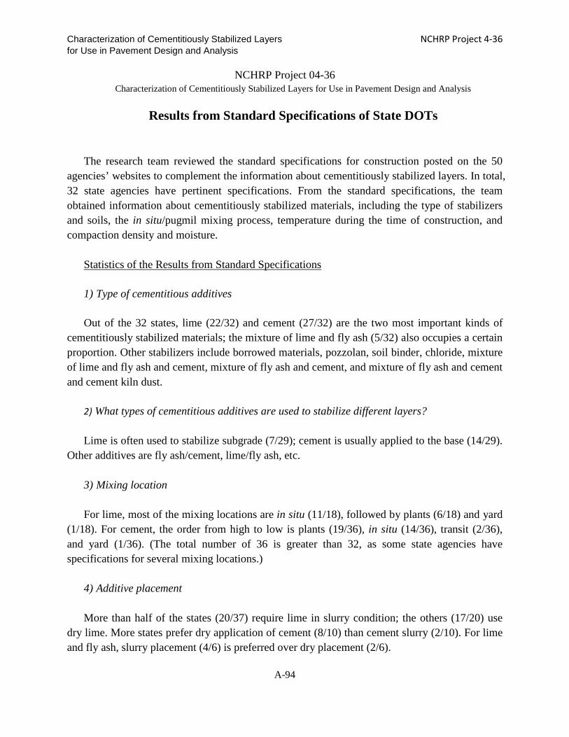
Characterization of Cementitiously Stabilized Layers NCHRP Project 4-36 for Use in Pavement Design and Analysis
NCHRP Project 04-36 Characterization of Cementitiously Stabilized Layers for Use in Pavement Design and Analysis
Results from Standard Specifications of State DOTs The research team reviewed the standard specifications for construction posted on the 50
agencies’ websites to complement the information about cementitiously stabilized layers. In total, 32 state agencies have pertinent specifications. From the standard specifications, the team obtained information about cementitiously stabilized materials, including the type of stabilizers and soils, the in situ/pugmil mixing process, temperature during the time of construction, and compaction density and moisture.
Statistics of the Results from Standard Specifications
1) Type of cementitious additives Out of the 32 states, lime (22/32) and cement (27/32) are the two most important kinds of
cementitiously stabilized materials; the mixture of lime and fly ash (5/32) also occupies a certain proportion. Other stabilizers include borrowed materials, pozzolan, soil binder, chloride, mixture of lime and fly ash and cement, mixture of fly ash and cement, and mixture of fly ash and cement and cement kiln dust.
2) What types of cementitious additives are used to stabilize different layers? Lime is often used to stabilize subgrade (7/29); cement is usually applied to the base (14/29).
Other additives are fly ash/cement, lime/fly ash, etc. 3) Mixing location For lime, most of the mixing locations are in situ (11/18), followed by plants (6/18) and yard
(1/18). For cement, the order from high to low is plants (19/36), in situ (14/36), transit (2/36), and yard (1/36). (The total number of 36 is greater than 32, as some state agencies have specifications for several mixing locations.)
4) Additive placement More than half of the states (20/37) require lime in slurry condition; the others (17/20) use
dry lime. More states prefer dry application of cement (8/10) than cement slurry (2/10). For lime and fly ash, slurry placement (4/6) is preferred over dry placement (2/6).
A-94

Characterization of Cementitiously Stabilized Layers NCHRP Project 4-36 for Use in Pavement Design and Analysis
5) Mix design Only a few state agencies have specifications for mix design. For example, California
specifies California Test 338 as the mix design method; Illinois’s mix design is based on “the Department’s Geotechnical Manual Procedure;” Oklahoma’s mix design is “OHD L 50/51.” Texas has different mix design methods: for lime the mix design is TX-121-E; for cement it is TX-120-E; and for the mixture of fly ash and lime it is TX-127-E.
6) Cut-off date/temperature All the agencies have specifications about cut-off date/temperature. The typical cut-off
temperature is around 40°F and cut-off date between April1st and the end of October. The temperature has to be above the freezing point during construction.
7) Placement after slurry When additive is applied for the slurry condition, it is specified to be mixed with the natural
soil within a time window since the production of slurry. Illinois and Mississippi require that the placement of lime slurry is less than 6 hours after the production of slurry. Virginia also requires that the placement of mixture of lime and fly ash should be less than 6 hours. The placement of cement slurry should be less than 30 minutes in Nevada and Virginia, and less than 2 hours in Texas.
8) Mixing delay The time of mixing delay after placement of an additive is different depending on the
additive. Lime has a longer time (4-6 hours) than cement (less than 1 hour). 9) Moisture tolerance during mixing Because density can reach the maximum value under the optimum moisture content, the
moisture during mixing should be around the optimum value. For soil-lime, the moisture content is specified above the optimum value to account for the evaporation during the longer mixing delay. For cement, the moisture content is specified to be in the range of -2% to +2% of the optimum value.
10) Mellowing time
A-95

Characterization of Cementitiously Stabilized Layers NCHRP Project 4-36 for Use in Pavement Design and Analysis
Mellowing time is needed when lime is used as the stabilizer. From the standard specifications, mellowing for more than two days is typical.
11) Compaction delay For soil-lime, the compaction is allowed to finish within 6-24 hours; 2 hours is typical for
cement-stabilized materials, and 4 hours for fly ash-stabilized materials. 12) Compaction moisture The results are similar to 8) Moisture tolerance during mixing. 13) Density target Most of the standard specifications require that the minimum value is 95% of the maximum
dry density based on either standard or modified proctor. 14) Time between compaction and curing After compaction, the layer should be cured under some special conditions. The time
between compaction and curing is specified to be less than 24 hours (8/11). 15) Curing method Asphalt curing is the most common curing method for any stabilized material. However,
when cement is the stabilizer, there are some other choices in several states. Kansas allows the use of a wax-based liquid membrane-forming compound, Pennsylvania the use of a white membrane forming curing compound, Tennessee the use of transparent or white polyethylene sheeting, and West Virginia the use of white polyethylene sheeting.
16) Minimum curing time Different states have different requirements; seven-day curing is the most common for
various cementitiously stabilized materials. 17) Curing temperature The temperature-specified curing process is the same as for the cut-off temperature. The
temperature is specified to be above the freezing point during curing. The typical minimum curing temperature is 40°F.
A-96

Characterization of Cementitiously Stabilized Layers NCHRP Project 4-36 for Use in Pavement Design and Analysis
Complete Listing of Standard Specifications for the NCHRP 04-36 Survey
Stat
e
Add
itive
Lay
er
Mix
ing
loca
tion
Add
itive
pl
acem
ent
Mix
des
ign
Cut
off
tem
p (°
F)
Plac
emen
t aft
er
slur
ry p
rodu
ctio
n
Mix
ing
Del
ay
Moi
stur
e to
lera
nce
duri
ng
mix
ing
Mel
low
ing
time
Com
pact
ion
Del
ay
Com
pact
ion
moi
stur
e
Den
sity
Tar
get
Tim
e be
twee
n co
mpa
ctio
n an
d cu
ring
Cur
ing
met
hod
Min
imum
cur
ing
time
Min
imum
Cur
ing
tem
p (F
)
Ala
bam
a
Lime
In si
tu
•dry
•s
lurr
y
Apr1 to Oct1 6 hr
±2% optimum
±2% optimum
±5% of AASHTO T
180
yard
±2%
optimum ±2%
optimum
plan
t
40F ±2%
optimum ±2%
optimum ±5%
cement
In si
tu
35F↑ or 40F
6 hr ±2% optimum
±2% optimum
±5% of AASHTO T
180
yard
±2%
optimum ±2%
optimum
plan
t
40F
±2% optimum
3 hr ±2%
optimum ±5%
Ari
zona
Lime subgrade
In si
tu
dry 40F
±2% optimum 24~48 hr
100% of maximum
density Bituminous 3 d
cement subgrade
In si
tu
dry 40F
±2%
optimum 2.5 hr
100% of maximum
density Bituminous 3 d
A-97

Characterization of Cementitiously Stabilized Layers NCHRP Project 4-36 for Use in Pavement Design and Analysis
Stat
e
Add
itive
Lay
er
Mix
ing
loca
tion
Add
itive
pl
acem
ent
Mix
des
ign
Cut
off
tem
p (°
F)
Plac
emen
t aft
er
slur
ry p
rodu
ctio
n
Mix
ing
Del
ay
Moi
stur
e to
lera
nce
duri
ng
mix
ing
Mel
low
ing
time
Com
pact
ion
Del
ay
Com
pact
ion
moi
stur
e
Den
sity
Tar
get
Tim
e be
twee
n co
mpa
ctio
n an
d cu
ring
Cur
ing
met
hod
Min
imum
cur
ing
time
Min
imum
Cur
ing
tem
p (F
)
cement base
plan
t
slur
ry
40F
±2% optimum
2.5 hr
100% of maximum
density
Bituminous 3 d
Ark
ansa
s
lime subgrade
In si
tu
•dry
•s
lurr
y
50F /
Apr1 to Oct31
±2%
optimum 3 d
»95% maximum
density
cement base
plan
t
dry 40F
60
min ±5%
optimum 2 hr
»95% maximum
density asphalt
cement crushed
stone base pl
ant
dry 40F
±1%
optimum asphalt 72 hr
Cal
iforn
ia
lime In
situ
•dry
•s
lurr
y
35F
7 d above optimum
« 24 hr
«48 hr asphalt 3 d 40F
cement
In si
tu
Cal
iforn
ia
Test
338
35F »99%
optimum 2.5 hr optimum asphalt 35F
plan
t
Cal
iforn
ia
Test
338
35F
»99% optimum
2.5 hr optimum
asphalt
35F
A-98

Characterization of Cementitiously Stabilized Layers NCHRP Project 4-36 for Use in Pavement Design and Analysis
Stat
e
Add
itive
Lay
er
Mix
ing
loca
tion
Add
itive
pl
acem
ent
Mix
des
ign
Cut
off
tem
p (°
F)
Plac
emen
t aft
er
slur
ry p
rodu
ctio
n
Mix
ing
Del
ay
Moi
stur
e to
lera
nce
duri
ng
mix
ing
Mel
low
ing
time
Com
pact
ion
Del
ay
Com
pact
ion
moi
stur
e
Den
sity
Tar
get
Tim
e be
twee
n co
mpa
ctio
n an
d cu
ring
Cur
ing
met
hod
Min
imum
cur
ing
time
Min
imum
Cur
ing
tem
p (F
)
Col
orad
o Lime In si
tu
slur
ry
35F » optimum » 48 hr
2 ± 1% percent
above the optimum
»95% maximum
density asphalt »7d 35F
Del
awar
e Borrow material
•dry
•s
lurr
y
±2% optimum
»100% maximum
density
Flor
ida
cement permeabl
e base plan
t
slur
ry
40 No
requirements 3~4 d
Geo
rgia
lime
•dry
•s
lurr
y
•45F •Apr1 to
Oct15
±5% optimum 3 ~14 d
100~102% optimum «24hr bituminous 7d
cement
In si
tu
40F
45 min
100~120 % optimum
2h 100~120 % optimum
»98% maximum
density
plan
t
40F
45 min
100~120 % optimum
2h 100~120 %
optimum
»98% maximum
density bituminous 7d
Illin
ois
lime
•dry
•s
lurr
y
45F 6hr 100~ 103%
optimum 48 hr »95% lab dry
density asphalt 7d
A-99

Characterization of Cementitiously Stabilized Layers NCHRP Project 4-36 for Use in Pavement Design and Analysis
Stat
e
Add
itive
Lay
er
Mix
ing
loca
tion
Add
itive
pl
acem
ent
Mix
des
ign
Cut
off
tem
p (°
F)
Plac
emen
t aft
er
slur
ry p
rodu
ctio
n
Mix
ing
Del
ay
Moi
stur
e to
lera
nce
duri
ng
mix
ing
Mel
low
ing
time
Com
pact
ion
Del
ay
Com
pact
ion
moi
stur
e
Den
sity
Tar
get
Tim
e be
twee
n co
mpa
ctio
n an
d cu
ring
Cur
ing
met
hod
Min
imum
cur
ing
time
Min
imum
Cur
ing
tem
p (F
)
cement pl
ant
dry
Dep
artm
ent's
G
eote
chni
cal
Man
ual
proc
edur
e
40F
80~ 110% optimum
2hr slightly » optimum
100% standard dry
density (AASHTO T
134)
bituminous 7d
pozzolanic pl
ant
dry 40F
90 min
80~ 110% optimum
slightly » optimum
1st lift, » 97% max density;
2nd,100% max density
«24hr asphalt
lime
fly a
sh,1
4hr;
cem
ent f
ly a
sh,1
2hr
Indi
ana fly
ash/lime/ceme
nt
Hyd
rate
d Li
me
and
Qui
cklim
e
45F
•cem
ent-
3hr
•fly
ash
- 4hr
•li
me-
24hr
100~102% optimum
100% maximum
density 72hr
Kan
sas lime subgrade
In si
tu
slur
ry
40F
»108% optimum
»24hr
asphalt 7d
plan
t
slur
ry
40F »108%
optimum »24hr asphalt 7d
cement/fly ash subgrade 40F
30 min
±3% optimum 2hr
»95% dry density asphalt 7d
A-100

Characterization of Cementitiously Stabilized Layers NCHRP Project 4-36 for Use in Pavement Design and Analysis
Stat
e
Add
itive
Lay
er
Mix
ing
loca
tion
Add
itive
pl
acem
ent
Mix
des
ign
Cut
off
tem
p (°
F)
Plac
emen
t aft
er
slur
ry p
rodu
ctio
n
Mix
ing
Del
ay
Moi
stur
e to
lera
nce
duri
ng
mix
ing
Mel
low
ing
time
Com
pact
ion
Del
ay
Com
pact
ion
moi
stur
e
Den
sity
Tar
get
Tim
e be
twee
n co
mpa
ctio
n an
d cu
ring
Cur
ing
met
hod
Min
imum
cur
ing
time
Min
imum
Cur
ing
tem
p (F
)
cement base
plan
t
2hr
»95% standard density
wax-based liquid
membrane-forming
compound
7d
Ken
tuck
y lime roadway
•dry
•s
lurr
y
40F 4 hr »optimum 48 hr
»95% maximum
density asphalt 7d
cement roadway
dry 40F
6 hr
100~ 102% optimum
»95% maximum
density asphalt 7d
Lou
isia
na
cement base
In si
tu
35F ±2%
optimum 3hr
»95% maximum
density asphalt 72hr
lime pl
ant
slur
ry
35F
»48hr 6hr
»95% maximum
density asphalt 72 hr
Mis
siss
ippi
lime In
situ
•dry
•s
lurr
y
40F 6hr
5~ 20d
»95% standard density
«24hr asphalt 7d 35F
cement In
situ
40F
3 hr « 102% optimum
4hr
»98% standard density
«24hr asphalt 7d
» fr
eezi
ng
A-101
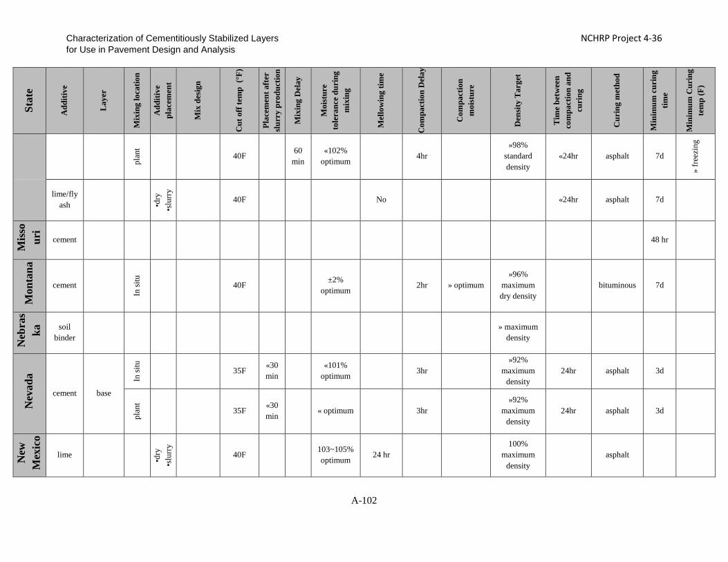
Characterization of Cementitiously Stabilized Layers NCHRP Project 4-36 for Use in Pavement Design and Analysis
Stat
e
Add
itive
Lay
er
Mix
ing
loca
tion
Add
itive
pl
acem
ent
Mix
des
ign
Cut
off
tem
p (°
F)
Plac
emen
t aft
er
slur
ry p
rodu
ctio
n
Mix
ing
Del
ay
Moi
stur
e to
lera
nce
duri
ng
mix
ing
Mel
low
ing
time
Com
pact
ion
Del
ay
Com
pact
ion
moi
stur
e
Den
sity
Tar
get
Tim
e be
twee
n co
mpa
ctio
n an
d cu
ring
Cur
ing
met
hod
Min
imum
cur
ing
time
Min
imum
Cur
ing
tem
p (F
)
plan
t
40F
60 min
«102% optimum
4hr
»98% standard density
«24hr asphalt 7d
» fr
eezi
ng
lime/fly ash
•dry
•s
lurr
y
40F No «24hr asphalt 7d
Mis
sour
i
cement
48 hr
Mon
tana
cement In
situ
40F
±2% optimum
2hr » optimum »96%
maximum dry density
bituminous 7d
Neb
ras
ka soil
binder
» maximum
density
Nev
ada
cement base
In si
tu
35F «30 min
«101% optimum 3hr
»92% maximum
density 24hr asphalt 3d
plan
t
35F «30 min
« optimum
3hr
»92% maximum
density 24hr asphalt 3d
New
M
exic
o
lime
•dry
•s
lurr
y
40F
103~105% optimum
24 hr
100% maximum
density
asphalt
A-102

Characterization of Cementitiously Stabilized Layers NCHRP Project 4-36 for Use in Pavement Design and Analysis
Stat
e
Add
itive
Lay
er
Mix
ing
loca
tion
Add
itive
pl
acem
ent
Mix
des
ign
Cut
off
tem
p (°
F)
Plac
emen
t aft
er
slur
ry p
rodu
ctio
n
Mix
ing
Del
ay
Moi
stur
e to
lera
nce
duri
ng
mix
ing
Mel
low
ing
time
Com
pact
ion
Del
ay
Com
pact
ion
moi
stur
e
Den
sity
Tar
get
Tim
e be
twee
n co
mpa
ctio
n an
d cu
ring
Cur
ing
met
hod
Min
imum
cur
ing
time
Min
imum
Cur
ing
tem
p (F
)
cement
40F 100~105% optimum 4hr
100% maximum
density asphalt 7d
New
Yor
k
lime In
situ
•dry
•s
lurr
y
40F
4 hr
24 hr 8hr
2d asphalt 14d
cement
In si
tu
40F
100~102% optimum
optimum »95%
maximum density
48hr bituminous 5d
plan
t
40F 30
min 100~102% optimum optimum
»95% maximum
density 48hr bituminous •5
d •f
reez
ing-
7d
Nor
th C
arol
ina
lime
•dry
•s
lurr
y
45F 2 hr 100~103% optimum 1~4d 4d
100~102% optimum
»97% maximum
density asphalt 7d
cement base
plan
t
40F 100~101.5% optimum 3hr
100~101.5% optimum
»97% maximum
density asphalt 7d
In si
tu
« optimum 3hr 100~101.5% optimum
»97% maximum
density asphalt 7d
A-103

Characterization of Cementitiously Stabilized Layers NCHRP Project 4-36 for Use in Pavement Design and Analysis
Stat
e
Add
itive
Lay
er
Mix
ing
loca
tion
Add
itive
pl
acem
ent
Mix
des
ign
Cut
off
tem
p (°
F)
Plac
emen
t aft
er
slur
ry p
rodu
ctio
n
Mix
ing
Del
ay
Moi
stur
e to
lera
nce
duri
ng
mix
ing
Mel
low
ing
time
Com
pact
ion
Del
ay
Com
pact
ion
moi
stur
e
Den
sity
Tar
get
Tim
e be
twee
n co
mpa
ctio
n an
d cu
ring
Cur
ing
met
hod
Min
imum
cur
ing
time
Min
imum
Cur
ing
tem
p (F
)
Nor
th D
akot
a
lime subgrade
•dry
•s
lurr
y
40F »optimum optimum bituminous
Lime /fly ash
subgrade
•dry
•s
lurr
y
40F
»optimum 24~48 hr
optimum
bituminous
cement base
plan
t
48 hr
Ohi
o
lime
Hyd
rate
d Li
me
and
Qui
cklim
e
40F »optimum 1~7d »optimum maximum dry density asphalt 5d
» fr
eezi
ng
cement
dry 40F
2 hr 100~103%
optimum »optimum maximum
dry density asphalt 5d
» fr
eezi
ng
Okl
aho
ma cement/
flyash/ CKD
subgrade
dry
OH
D L
50
/51
40F
102~105% optimum
±2% optimum
»95% target density
A-104

Characterization of Cementitiously Stabilized Layers NCHRP Project 4-36 for Use in Pavement Design and Analysis
Stat
e
Add
itive
Lay
er
Mix
ing
loca
tion
Add
itive
pl
acem
ent
Mix
des
ign
Cut
off
tem
p (°
F)
Plac
emen
t aft
er
slur
ry p
rodu
ctio
n
Mix
ing
Del
ay
Moi
stur
e to
lera
nce
duri
ng
mix
ing
Mel
low
ing
time
Com
pact
ion
Del
ay
Com
pact
ion
moi
stur
e
Den
sity
Tar
get
Tim
e be
twee
n co
mpa
ctio
n an
d cu
ring
Cur
ing
met
hod
Min
imum
cur
ing
time
Min
imum
Cur
ing
tem
p (F
)
lime sugrade
slur
ry:p
lant
/ tra
nsit
•dry
•s
lurr
y
OH
D L
50/
51
40F 102~105% optimum
•hyd
rate
d: 7
2hr
•qui
ck:4
8hr
±2%
optimum »95% target
density
cement base 40F
2hr
»95% standard density
7d
Ore
gon
lime subgrade
optimum 12hr 96~102% optimum
»95% maximum
density 7d
chloride subgrade
optimum
12hr
96~102% optimum
»95% maximum
density 7d
cement subgrade
optimum 12hr 96~102% optimum
»95% maximum
density 7d
Penn
sylv
ania
cement base
•pla
nt
•truc
k
40F
1hr
white membrane forming curing
compound
•40F
-24h
r •3
2~40
F- 4
8hr
32F
Sout
h C
arol
ina cement
modified subbase In
situ
dry 40F
3 hr «optimum
2hr
±2% optimum
»95% maximum
density asphalt 3d
A-105

Characterization of Cementitiously Stabilized Layers NCHRP Project 4-36 for Use in Pavement Design and Analysis
Stat
e
Add
itive
Lay
er
Mix
ing
loca
tion
Add
itive
pl
acem
ent
Mix
des
ign
Cut
off
tem
p (°
F)
Plac
emen
t aft
er
slur
ry p
rodu
ctio
n
Mix
ing
Del
ay
Moi
stur
e to
lera
nce
duri
ng
mix
ing
Mel
low
ing
time
Com
pact
ion
Del
ay
Com
pact
ion
moi
stur
e
Den
sity
Tar
get
Tim
e be
twee
n co
mpa
ctio
n an
d cu
ring
Cur
ing
met
hod
Min
imum
cur
ing
time
Min
imum
Cur
ing
tem
p (F
)
cement modified recycled
base In si
tu
40F «optimum 2hr asphalt 3d
cement stabilzied earth base
In si
tu
40F ±2%
optimum 2hr ±2%
optimum
»95% maximum
density «12hr asphalt 7d
plan
t
40F
60 min
«102% optimum
2hr ±2% optimum
»95% maximum
density «12hr asphalt 7d
cement
stabilzied
aggregate base
Ten
ness
ee
lime subgrade
In si
tu
•dry
•s
lurr
y
40F 102~108% optimum 2~7d
±3% optimum
»95% maximum
density bituminous
lime/ fly ash base
In si
tu
hydr
ated
Li
me 40F
±2%
optimum 8hr 99~103%
optimum
»100% maximum
density «24hr bituminous 7d
plan
t
hydr
ated
Li
me 40F
±2%
optimum 8hr
99~103% optimum
»100% maximum
density «24hr bituminous 7d
A-106

Characterization of Cementitiously Stabilized Layers NCHRP Project 4-36 for Use in Pavement Design and Analysis
Stat
e
Add
itive
Lay
er
Mix
ing
loca
tion
Add
itive
pl
acem
ent
Mix
des
ign
Cut
off
tem
p (°
F)
Plac
emen
t aft
er
slur
ry p
rodu
ctio
n
Mix
ing
Del
ay
Moi
stur
e to
lera
nce
duri
ng
mix
ing
Mel
low
ing
time
Com
pact
ion
Del
ay
Com
pact
ion
moi
stur
e
Den
sity
Tar
get
Tim
e be
twee
n co
mpa
ctio
n an
d cu
ring
Cur
ing
met
hod
Min
imum
cur
ing
time
Min
imum
Cur
ing
tem
p (F
)
cement permeable base In
situ
transparent or white
polyethylene sheeting
7d
Tex
as
Lime
In si
tu
Lim
e sl
urry
TX-1
21-E
35F↑or 40F
6 hr
•1-4
Day
s •2
-4 D
ays (
Pebb
le Q
uick
lime)
95%
asphalt
•PI«
35,2
d •P
I>35
,5d
Plan
t
Lim
e sl
urry
TX-1
21-E
35F↑or 40F
6 hr
95%
asphalt 7d
Cement
In si
tu
cem
ent
slur
ry
Tex-
120-
E
35F↑or 40F «2hr
±2% optimum «2 hr
±2% optimum 95% asphalt »3d
Plan
t
cem
ent
slur
ry
Tex-
120-
E
35F↑or 40F «2hr
±2% optimum «2 hr
±2% optimum 95% asphalt »3d
A-107
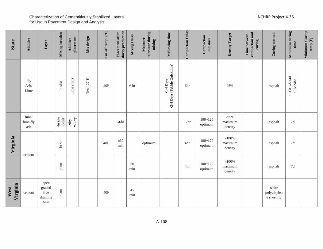
Characterization of Cementitiously Stabilized Layers NCHRP Project 4-36 for Use in Pavement Design and Analysis
Stat
e
Add
itive
Lay
er
Mix
ing
loca
tion
Add
itive
pl
acem
ent
Mix
des
ign
Cut
off
tem
p (°
F)
Plac
emen
t aft
er
slur
ry p
rodu
ctio
n
Mix
ing
Del
ay
Moi
stur
e to
lera
nce
duri
ng
mix
ing
Mel
low
ing
time
Com
pact
ion
Del
ay
Com
pact
ion
moi
stur
e
Den
sity
Tar
get
Tim
e be
twee
n co
mpa
ctio
n an
d cu
ring
Cur
ing
met
hod
Min
imum
cur
ing
time
Min
imum
Cur
ing
tem
p (F
)
Fly Ash/ Lime
In si
tu
Lim
e sl
urry
Tex-
127-
E 40F 6 hr
•1-4
Day
s •2
-4 D
ays (
Pebb
le Q
uick
lime)
6hr 95% asphalt
•LFA
:7d-
14d
•FA
:24h
r
Vir
gini
a
lime/ lime-fly
ash •I
n si
tu
•pla
nt
•dry
•s
lurr
y
«6hr 12hr 100~120 optimum
»95% maximum
density asphalt 7d
cement
In si
tu
40F «30min
optimum
4hr 100~120 optimum
»100% maximum
density
asphalt 7d
plan
t
60
min 4hr
100~120 optimum
»100% maximum
density asphalt 7d
Wes
t V
irgi
nia
cement
open graded
free draining
base
plan
t
40F
45 min
white polyethylene sheeting
A-108
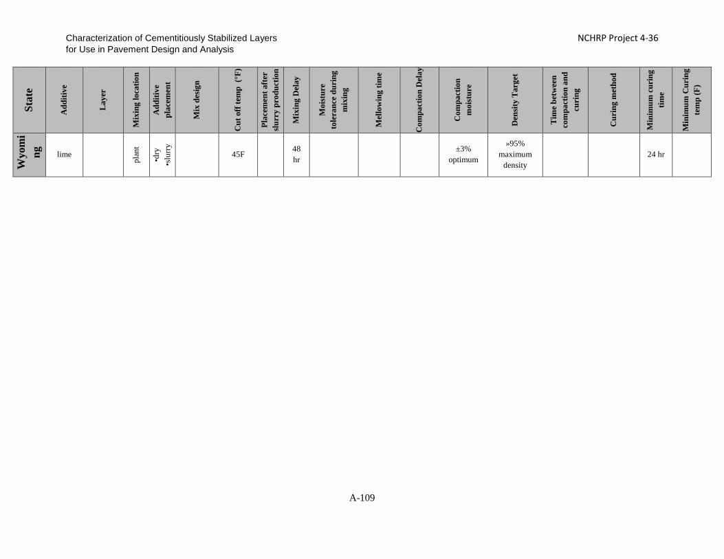
Characterization of Cementitiously Stabilized Layers NCHRP Project 4-36 for Use in Pavement Design and Analysis
Stat
e
Add
itive
Lay
er
Mix
ing
loca
tion
Add
itive
pl
acem
ent
Mix
des
ign
Cut
off
tem
p (°
F)
Plac
emen
t aft
er
slur
ry p
rodu
ctio
n
Mix
ing
Del
ay
Moi
stur
e to
lera
nce
duri
ng
mix
ing
Mel
low
ing
time
Com
pact
ion
Del
ay
Com
pact
ion
moi
stur
e
Den
sity
Tar
get
Tim
e be
twee
n co
mpa
ctio
n an
d cu
ring
Cur
ing
met
hod
Min
imum
cur
ing
time
Min
imum
Cur
ing
tem
p (F
)
Wyo
mi
ng
lime plan
t
•dry
•s
lurr
y
45F 48 hr
±3% optimum
»95% maximum
density 24 hr
A-109

Characterization of Cementitiously Stabilized Layers NCHRP Project 4-36 for Use in Pavement Design and Analysis
Appendix B. Mix Design and Test Procedure Evaluation
B-1

Characterization of Cementitiously Stabilized Layers NCHRP Project 4-36 for Use in Pavement Design and Analysis CONTENTS LIST OF FIGURES ................................................................................................................................. B-4
LIST OF TABLES ................................................................................................................................... B-6
CHAPTER B-1. MIX DESIGN............................................................................................................... B-7
Soil-Cement .......................................................................................................................................... B-7
Soil-Fly Ash (Class C) .......................................................................................................................... B-7
Soil-Lime ............................................................................................................................................... B-8
Summary of Mix Design .................................................................................................................... B-10
CHAPTER B-2. APPRAISAL AND LABORATORY EVALUATION OF TEST PROCEDURES . B-11
Strength Tests ..................................................................................................................................... B-11
Modulus Tests..................................................................................................................................... B-12
Durability Tests .................................................................................................................................. B-15
Erodibility Tests ................................................................................................................................. B-17
Fatigue Tests ....................................................................................................................................... B-17
Shrinkage Tests .................................................................................................................................. B-20
Friction/Bond...................................................................................................................................... B-21
CHAPTER B-3. LABORATORY TEST PROCEDURE EVALUATION ....................................... B-23
Indirect Tensile (IDT) Test ............................................................................................................... B-25
Flexural Beam Tests .......................................................................................................................... B-29
Stress-Wave Base Modulus Test ....................................................................................................... B-35
Durability Tests .................................................................................................................................. B-41
Wet-Dry Durability Test................................................................................................................... B-41
Freeze-Thaw Durability Test ........................................................................................................... B-42
Vacuum Saturation Test ................................................................................................................... B-42
Large-Scale Model Experiment (LSME) ......................................................................................... B-45
Shrinkage and Cracking .................................................................................................................... B-50
Coefficient of Thermal Expansion (COTE) Test .............................................................................. B-50
Bond Strength Test ........................................................................................................................... B-52
Free Autogenous Shrinkage ............................................................................................................. B-55
Free Drying Shrinkage..................................................................................................................... B-57
B-2

Characterization of Cementitiously Stabilized Layers NCHRP Project 4-36 for Use in Pavement Design and Analysis
Restrained Drying Shrinkage Cracking ........................................................................................... B-61
Erodibility ........................................................................................................................................... B-64
REFERENCES ....................................................................................................................................... B-70
B-3
Characterization of Cementitiously Stabilized Layers NCHRP Project 4-36 for Use in Pavement Design and Analysis LIST OF FIGURES Figure B-1. Results for UCS after 7-day Curing for Cement-Stabilized Soils ........................... B-7 Figure B-2. Results for UCS after 7-day Curing for Class C Fly Ash-Stabilized Soils ............. B-8 Figure B-3. pH Value vs. Lime Content ..................................................................................... B-9 Figure B-4. Results for UCS after 7-day Curing for Clay-Lime Mix ......................................... B-9 Figure B-5. Results for UCS after 7-day Curing for Silt-Lime-Class F Fly Ash ..................... B-10 Figure B-6. Indirect Tensile (IDT) Strength Test Setup ........................................................... B-26 Figure B-7. IDT Modulus Test Setup ....................................................................................... B-27 Figure B-8. Modulus of Rupture Test Setup ............................................................................. B-30 Figure B-9. Flexural Modulus Test Setup................................................................................. B-31 Figure B-10. Typical Degradation of Flexural Modulus in Fatigue Test of Gravel-Cement ... B-32 Figure B-11. View of Stress-Wave Base Modulus Test Specimens ......................................... B-36 Figure B-12. Seismic Modulus Test Setup ............................................................................... B-36 Figure B-13. View of the Ultrasonic Test Setup....................................................................... B-37 Figure B-14. Variation in Modulus Results Obtained from Seismic and Ultrasonic Tests for
Gravel-Cement Specimens .................................................................................... B-38 Figure B-15. Variation in Modulus Results Obtained from Seismic and Ultrasonic Tests for
Clay-Lime Specimens ........................................................................................... B-38 Figure B-16. Effect of Saturation on P-wave Velocity (Fratta et al. 2005) .............................. B-39 Figure B-17. Effect of Moisture Content on Constrained Modulus ......................................... B-41 Figure B-18. Vacuum Test Setup.............................................................................................. B-43 Figure B-19. UCS with and without Vacuum Saturation for Gravel-Cement .......................... B-44 Figure B-20. UCS of Unsaturated and Saturated Specimens ................................................... B-45 Figure B-21. Schematic of LSME Setup, 1 m = 3.3 ft (Schaertl 2010) .................................... B-46 Figure B-22. Elastic Deflections of Recycled Pavement Material before and after Crack
Observation (25.4 mm = 1 in.) .............................................................................. B-47 Figure B-23. Observed Crack on Gravel-Cement Surface ....................................................... B-48 Figure B-24. Measured Deflections for Gravel-Cement with Foam at 6000 lbs ...................... B-48 Figure B-25. Observed Crack in Silt-Cement Surface .............................................................. B-49 Figure B-26. COTE Development of Clay-Lime Specimens ................................................... B-51 Figure B-27. COTE Development of Gravel-Cement Specimens ............................................ B-51 Figure B-28. Bond Strength under Constant Loading Rate for Cement-Gravel (71.6 psi/min) B-52 Figure B-29. Bond Strength under Constant Deformation Rate for Cement-Gravel (0.065
in./min) .................................................................................................................. B-53 Figure B-30. Bond Strength Test when Cement Mortar is used as Bonding Agent ................. B-54 Figure B-31. Bond Strength Test when Epoxy is used as Bonding Agent ............................... B-55 Figure B-32. Failure Surfaces after Bond Strength Tests ......................................................... B-55 Figure B-33. Plaster Mold......................................................................................................... B-56 Figure B-34. Autogenous Shrinkage Test Setup ....................................................................... B-56
B-4

Characterization of Cementitiously Stabilized Layers NCHRP Project 4-36 for Use in Pavement Design and Analysis Figure B-35. Autogenous Shrinkage Results of Clay-Lime and Gravel-Cement Specimens .. B-57 Figure B-36. Compaction Mold for Free Shrinkage Test ......................................................... B-58 Figure B-37. Test Setup to Evaluate the Effects of Specimen Dimension and Bottom Surface .. B-
58 Figure B-38. Effects of Specimen Dimension and Bottom Surface ......................................... B-59 Figure B-39. Drying Shrinkage Test ......................................................................................... B-59 Figure B-40. Test Results for Drying Shrinkage Evaluation .................................................... B-60 Figure B-41. Free Drying and Autogenous Shrinkage Results for Clay-Lime Specimens ...... B-60 Figure B-42. Free Drying and Autogenous Shrinkage Results for Gravel-Cement Specimens B-61 Figure B-43. Restrained Shrinkage Test for Clay-Lime when Epoxy is used as Bonding Agent
(48 in. Long) .......................................................................................................... B-62 Figure B-44. Restrained Shrinkage Test for Clay-Lime when Cement Mortar is used as Bonding
Agent (48 in. Long) ............................................................................................... B-62 Figure B-45. Crack Width Increase over Time for Clay-Lime Specimen when Epoxy is used as
Bonding Agent ...................................................................................................... B-62 Figure B-46. Crack Width Increase over Time for Clay-Lime Specimen when Cement Mortar is
used as Bonding Agent .......................................................................................... B-63 Figure B-47. Restrained Shrinkage for Gravel-Cement when Epoxy is used as Bonding Agent
(92 in. Long) .......................................................................................................... B-63 Figure B-48. Rotational Shear Device ...................................................................................... B-64 Figure B-49. RSD Results for Clay-Lime Specimens .............................................................. B-66 Figure B-50. Strips inside the Cylinder .................................................................................... B-66 Figure B-51. Effects of Strips on Shear Stress ......................................................................... B-67 Figure B-52. HET Setup with High-Pressure Water ................................................................ B-68 Figure B-53. CIE Test Setup ..................................................................................................... B-69 Figure B-54. Modulus Reduction with Number of Load Cycles .............................................. B-69
B-5

Characterization of Cementitiously Stabilized Layers NCHRP Project 4-36 for Use in Pavement Design and Analysis LIST OF TABLES Table B-1. Final Mix Design of Stabilized Mixtures ............................................................... B-10 Table B-2. Maximum Dry Density and Optimum Moisture Content ....................................... B-10 Table B-3. Appraisal of Material Strength Tests ...................................................................... B-13 Table B-4. Appraisal of Stiffness Tests .................................................................................... B-14 Table B-5. Appraisal of Durability Tests .................................................................................. B-16 Table B-6. Evaluation of Erodibility Tests ............................................................................... B-18 Table B-7. Evaluation of Fatigue Tests .................................................................................... B-19 Table B-8. Appraisal of Test Methods for Shrinkage and Swelling ......................................... B-22 Table B-9. Test Procedures Selected for Evaluation ................................................................ B-23 Table B-10. Parameters for IDT Modulus Test ........................................................................ B-28 Table B-11. Summary of IDT Strength Test Results ................................................................ B-28 Table B-12. Summary of IDT Modulus Test Results ............................................................... B-28 Table B-13. Summary of IDT Fatigue Test Results ................................................................. B-29 Table B-14. Summary of MOR Test Results (Gravel-Cement 4%) ......................................... B-33 Table B-15. Summary of Flexural Modulus Test Results (Gravel-Cement 4%) ...................... B-33 Table B-16. Summary of Flexural Fatigue Test Results (Gravel-Cement 4%) ........................ B-33 Table B-17. Summary of Flexural Test Results (Gravel-Cement 3%) ..................................... B-34 Table B-18. Summary of MOR Test Results (Clay-Lime 5%) ................................................ B-34 Table B-19. Summary of Flexural Modulus Test Results (Clay-Lime 5%) ............................. B-35 Table B-20. Summary of Flexural Fatigue Test Results (Clay-Lime 5%) ............................... B-35 Table B-21. Wet-Dry Test Results............................................................................................ B-42 Table B-22. Freeze-Thaw Test Results ..................................................................................... B-42 Table B-23. Test Results of Vacuum Saturation for Gravel-Cement Specimens ..................... B-43 Table B-24. Test Results of Vacuum Saturation for Clay-Lime Specimens ............................ B-44 Table B-25. Results of Bond Strength Tests ............................................................................. B-54
B-6
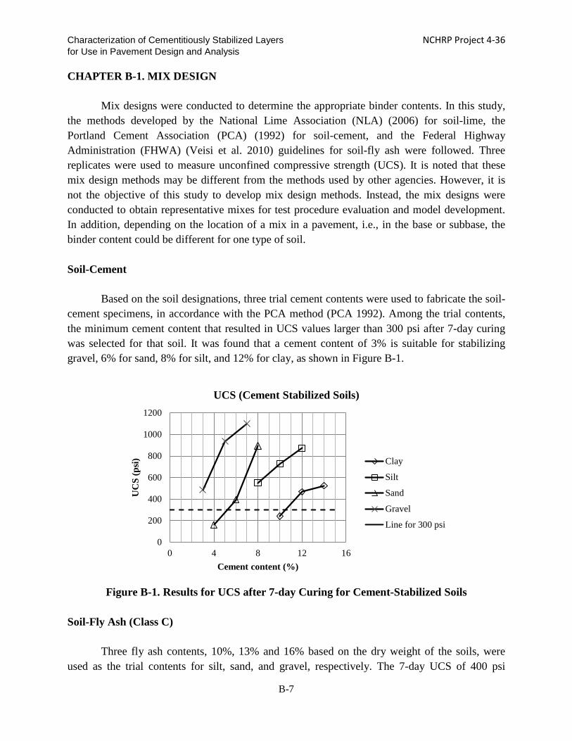
Characterization of Cementitiously Stabilized Layers NCHRP Project 4-36 for Use in Pavement Design and Analysis CHAPTER B-1. MIX DESIGN
Mix designs were conducted to determine the appropriate binder contents. In this study,
the methods developed by the National Lime Association (NLA) (2006) for soil-lime, the Portland Cement Association (PCA) (1992) for soil-cement, and the Federal Highway Administration (FHWA) (Veisi et al. 2010) guidelines for soil-fly ash were followed. Three replicates were used to measure unconfined compressive strength (UCS). It is noted that these mix design methods may be different from the methods used by other agencies. However, it is not the objective of this study to develop mix design methods. Instead, the mix designs were conducted to obtain representative mixes for test procedure evaluation and model development. In addition, depending on the location of a mix in a pavement, i.e., in the base or subbase, the binder content could be different for one type of soil.
Soil-Cement
Based on the soil designations, three trial cement contents were used to fabricate the soil-
cement specimens, in accordance with the PCA method (PCA 1992). Among the trial contents, the minimum cement content that resulted in UCS values larger than 300 psi after 7-day curing was selected for that soil. It was found that a cement content of 3% is suitable for stabilizing gravel, 6% for sand, 8% for silt, and 12% for clay, as shown in Figure B-1.
Figure B-1. Results for UCS after 7-day Curing for Cement-Stabilized Soils
Soil-Fly Ash (Class C)
Three fly ash contents, 10%, 13% and 16% based on the dry weight of the soils, were
used as the trial contents for silt, sand, and gravel, respectively. The 7-day UCS of 400 psi
0
200
400
600
800
1000
1200
0 4 8 12 16
UC
S (p
si)
Cement content (%)
UCS (Cement Stabilized Soils)
Clay
Silt
Sand
Gravel
Line for 300 psi
B-7

Characterization of Cementitiously Stabilized Layers NCHRP Project 4-36 for Use in Pavement Design and Analysis specified by the FHWA (Veisi et al. 2010) cannot be achieved for the gravel mixes or silt mixes, as shown in Figure B-2. Increasing the fly ash content did not significantly increase the strength of the gravel or silt mixes. Instead, 13% fly ash was used for stabilizing the silt, sand, and gravel, because this percentage has been used successfully in past studies and is consistent with the content used by some agencies, such as the Oklahoma DOT.
Figure B-2. Results for UCS after 7-day Curing for Class C Fly Ash-Stabilized Soils
Soil-Lime
According to the design method developed by the NLA (2006), the initial lime content was determined based on the Eade and Grim method. Different lime contents were added to a soil and water solution. The lime content that led to a pH of 12.49 was the initial lime content used for further laboratory evaluation in terms of strength. For clay-lime, 2% lime, based on the dry mass of clay, is the lime content needed to reach a pH of 12.49 (Figure B-3). Therefore, 2%, 4%, and 6% lime were used to fabricate specimens for strength testing to determine the minimum lime content for the clay-lime mix. It was found that 6% lime can lead to the UCS of 70 psi, which is specified by the NLA (2006) (Figure B-4).
0
100
200
300
400
500
600
700
7 10 13 16 19
UC
S (p
si)
Class C Fly ash content (%)
UCS (Class C Fly Ash Stabilized Soils)
Silt
Sand
Gravel
Line for 400 psi
B-8

Characterization of Cementitiously Stabilized Layers NCHRP Project 4-36 for Use in Pavement Design and Analysis
Figure B-3. pH Value vs. Lime Content
Figure B-4. Results for UCS after 7-day Curing for Clay-Lime Mix
Because the plasticity index (PI) of the silt is less than 10, this silt is not suitable for lime
stabilization, in accordance with the NLA design method (2006). The team used lime and Class F fly ash to stabilize the silt. In accordance with the Mechanistic-Empirical Pavement Design Guide (MEPDG) (ARA 2004), the UCS should be at a minimum of 200 psi after 7-day curing and 4-hour soaking in water. This requirement can be achieved with 4% lime and 12% Class F fly ash, based on the dry mass of silt, as indicated in Figure B-5.
7
8
9
10
11
12
13
14
0 20 40 60 80 100
pH
Lime content (%)
Lime Content-pH (Clay)
0
20
40
60
80
100
0 2 4 6 8
UC
S (p
si)
Lime content (%)
UCS (Clay-Lime)
Clay-Lime
Line for 70psi
B-9
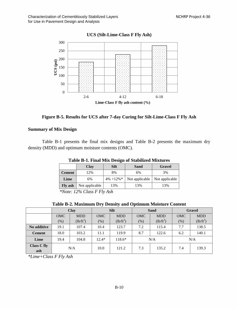
Characterization of Cementitiously Stabilized Layers NCHRP Project 4-36 for Use in Pavement Design and Analysis
Figure B-5. Results for UCS after 7-day Curing for Silt-Lime-Class F Fly Ash
Summary of Mix Design
Table B-1 presents the final mix designs and Table B-2 presents the maximum dry
density (MDD) and optimum moisture contents (OMC).
Table B-1. Final Mix Design of Stabilized Mixtures
Clay Silt Sand Gravel Cement 12% 8% 6% 3%
Lime 6% 4% +12%* Not applicable Not applicable
Fly ash Not applicable 13% 13% 13% *Note: 12% Class F Fly Ash
Table B-2. Maximum Dry Density and Optimum Moisture Content
Clay Silt Sand Gravel
OMC (%)
MDD (lb/ft3)
OMC (%)
MDD (lb/ft3)
OMC (%)
MDD (lb/ft3)
OMC (%)
MDD (lb/ft3)
No additive 19.1 107.4 10.4 123.7 7.2 115.4 7.7 138.5 Cement 18.0 103.2 11.1 119.9 8.7 122.6 6.2 140.1
Lime 19.4 104.8 12.4* 118.6* N/A N/A Class C fly
ash N/A 10.0 121.2 7.3 135.2 7.4 139.3
*Lime+Class F Fly Ash
0
50
100
150
200
250
300
2-6 4-12 6-18
UC
S (p
si)
Lime-Class F fly ash content (%)
UCS (Silt-Lime-Class F Fly Ash)
B-10

Characterization of Cementitiously Stabilized Layers NCHRP Project 4-36 for Use in Pavement Design and Analysis CHAPTER B-2. APPRAISAL AND LABORATORY EVALUATION OF TEST PROCEDURES
The test procedures needed to characterize the material properties are appraised in the following sections. These appraisals are based either on the literature review, or the team’s experience or understanding. These test procedures were then evaluated in the laboratory. Strength Tests
The types of strength tests for cementitiously stabilized materials (CSM) include UCS, indirect tensile (IDT) strength, tensile strength, modulus of rupture (MOR), and direct shear strength tests. Table B-3 presents the appraisal and recommendations of test procedures that are relevant to the strength of CSM.
Unconfined Compressive Strength Test: UCS is recommended as a Level 1 material property, which is a key parameter in the top-down compressive fatigue model. UCS testing also correlates well with other strength and modulus tests for Level 2 input. Most state highway agencies use UCS tests for mix design and for quality assurance/quality control (QA/QC) because of the simplicity of the tests. UCS testing is well-established and meets all cost, practicality and availability requirements (Yeo et al. 2002). UCS also is used in CSM mix design procedures. AASHTO T22, ASTM D1633, ASTM D5102, and ASTM C593 are test methods used for lean concrete, soil cement, lime-stabilized materials, and fly ash-stabilized materials with or without lime, respectively.
Modulus of Rupture Test: MOR, or flexural strength, is recommended as a Level 1 input for fatigue models of heavily stabilized materials because the MOR test simulates the resistance to cracking due to bending for CSL in the field. The MEPDG (ARA 2004) specifies AASHTO T97, Standard Method of Test for Flexural Strength of Concrete (Using Simple Beam with Third-Point Loading), or ASTM D1635, Standard Test Method for Flexural Strength of Soil-Cement Using Simple Beam with Third-Point Loading.
Indirect Tensile Strength Test: IDT strength testing is recommended for measuring tensile strength for Level I input to the shrinkage cracking model for both heavily and lightly stabilized materials, because direct tensile strength is difficult to measure. The IDT strength value is close to that of tensile strength and the test correlates well with other strength tests. Furthermore, the IDT test procedure is practical and repeatable.
The IDT strength can be obtained in accordance with the splitting test: AASHTO T198,
Splitting Tensile Strength of Cylindrical Concrete Specimens, which specifies the specimen geometry of 6 inches in diameter and 12 inches in height. The specified loading rate of the
B-11

Characterization of Cementitiously Stabilized Layers NCHRP Project 4-36 for Use in Pavement Design and Analysis splitting tensile stress by AASHTO T198 is 100-200 psi/min. The size and loading rate may not be appropriate for soil-lime or soil-fly ash/lime, which are relatively weak materials. The Australian method (Midgley and Yeo 2008) used to determine the IDT strength of stabilized materials is recommended. The specimen sizes are either 4 inches in diameter and 2.4 inches in height or 6 inches in diameter and 3.3 inches in height, depending on the size of the soil/aggregate particles. The loading rate is 4500 lbs/min. Modulus Tests
Modulus tests of CSM include resilient modulus, IDT modulus, flexural modulus, modulus of elasticity, seismic modulus, and acoustic modulus tests. Table B-4 presents the appraisal and recommendations of these test procedures to characterize the modulus of CSM.
Flexural Modulus Test: The flexural modulus test is recommended for characterizing heavily stabilized material, because the flexural modulus simulates bending conditions in the field. It is a dynamic and small-strain modulus, instead of a static and large-strain modulus, such as the modulus of elasticity. The use of the flexural modulus test also corresponds with the MOR tests recommended previously for different strength tests that share the same specimen. Currently, there is no standard for the flexural modulus test. The Australian test method used to determine the flexural modulus (Midgley and Yeo 2008) for CSM is evaluated in this study.
Resilient Modulus Test: Even though resilient modulus testing is time-consuming, the resilient modulus test is recommended for lightly stabilized materials, such as soil-lime, because it takes into account the effects of confining pressure on the resilient modulus. The compressive modulus is suitable when the lightly stabilized material is located deep in the pavement structure, such as in the subbase. AASHTO T307 is recommended by the current MEPDG (ARA 2004) to measure the resilient modulus of lightly stabilized materials.
Seismic Modulus Test: Both UCS and seismic modulus tests are recommended for modulus prediction as the Level 2 correlation for both heavily and lightly stabilized materials. Unlike UCS testing, seismic modulus testing is nondestructive and can be used to determine the modulus growth using the same specimen. The seismic modulus test is simple, repeatable, and inexpensive. Also, it has been shown to correlate very well with other modulus tests. The seismic modulus test can be based either on ASTM C215-08, Standard Test Method for Fundamental Transverse, Longitudinal, and Torsional Frequencies of Concrete Specimens, or the Texas DOT free-free resonant column (FFRC) test, Tex-147-E. Tex-147-E is evaluated in this study to determine its correlation with other modulus tests because it has been used extensively for CSM in the past.
B-12

Characterization of Cementitiously Stabilized Layers NCHRP Project 4-36 for Use in Pavement Design and Analysis
Table B-3. Appraisal of Material Strength Tests
Unconfined Compressive Strength (UCS)
Indirect Tensile Strength (IDT)
Direct Tensile Strength (DT)
Modulus of Rupture (MOR) Direct Shear Strength
Performance Predictability
Good (a key parameter in the top-down compressive fatigue model; correlates well with modulus and
other strength tests)
Good (predicts direct tensile strength well, which correlates
with shrinkage cracking potential)
Good (predicts shrinkage cracking potential well,
which is a key parameter in prediction model)
Good (predicts fatigue resistance well, which is a key parameter in prediction model)
Good (predicts erosion resistance well, which is
a key parameter in prediction model)
Precision Average (COV typically below
20%) (White 2005)
Good (COV typically below 10% ) (White 2005, Hudson and
Kennedy 1968) Unknown Average (COV around 20%) Poor (Kaniraj and
Havanagi 2001)
Accuracy Good (correlates well with modulus and strength tests)
Good (0.9-1.1 of direct tensile strength) (Bonnot 1991)
Good (direct measurement of tensile strength)
(Hudson and Kennedy 1968)
Good (direct measurement of modulus of rupture)
Poor (failure plane difficult to control for
stiff materials)
Practicality
Good (well established strength test, and meets cost, practicality, and availability requirements; not for tensile strength and fatigue)
(Yeo et al. 2002)
Good (practical, productive, economic, and user friendly
(Yeo et al. 2002); same type of specimen and equipment as that used for compression testing) (Hudson and Kennedy 1968)
Poor (misalignment for pure tension, failure
outside central portion (Yeo et al. 2002); gripping
specimen is difficult (Hudson and Kennedy
1968)
Average (difficult to obtain field samples (Yeo 2008);
good for high stiffness materials; beam is hard to
prepare and handle (Gnanendran and Piratheepan
2008)
Average (difficult for stiff and cemented
materials)
Machine Costs Low Low Average Low Low
Time Short Short Average (3 hr preparation of specimens) Short Short
Recommendation
Recommended for compressive fatigue model as Level 1 input and Level 2 for prediction of modulus
and other strength tests
Recommended for shrinkage cracking as Level 1
Not recommended due to operational difficulties
Recommended for fatigue model as Level 1
Not recommended due to impracticality
Note: Cost Ratings: High: >$50,000; Medium: $20,000 to $50,000; Low: <$20,000; Very Low: <$5,000
B-13

Characterization of Cementitiously Stabilized Layers NCHRP Project 4-36 for Use in Pavement Design and Analysis
Table B-4. Appraisal of Stiffness Tests
Resilient Modulus (Mr)
IDT Modulus Flexural Modulus Modulus of Elasticity
Seismic Modulus (SM)
Acoustic Modulus (AM)
Performance Predictability
Good (simulates compression in the
field and accounts for confining pressure)
Average (simulates shrinkage/tensile behavior of CSL)
Good (simulates field bending
conditions; dynamic loads)
Poor (fundamental properties; but test does not simulate
field bending conditions)
Average (does not simulate field
bending conditions)
Average (does not simulate field
bending conditions)
Precision Average (mixed
results) (Scullion et al. 2008)
Average (mixed results) (White 2005)
Average (COV below 20%) (Yeo
2008, Carteret 2009)
Average (COV below 20%)
(Richardson 1996)
Good (repeatable and COV typically
below 7%) (Hilbrich and
Scullion 2007)
Good (repeatable) (Yesiller et al.
2001)
Accuracy
Good (compressive modulus for lightly stabilized materials used in subbase )
Good (direct measurement of tensile
behavior)
Good (direct measurement)
Average (compressive and
static moduli, instead of bending or tensile moduli)
Good (correlates well with other
moduli) (Hilbrich and Scullion 2007)
Good (correlates well with stiffness)
(Yesiller et al. 2001)
Practicality
Poor (has some dependence on stress
levels and is very sensitive to the test procedure; test is complex and very time-consuming)
(Hilbrich and Scullion 2007)
Average (relatively practical and user
friendly; stress/strain control is difficult with
brittle stabilized materials; suitable for
lightly stabilized materials) (Yeo 2002)
Average (beam samples are difficult to manufacture in the laboratory; can use
the same beam specimen for
modulus of rupture) (Yeo 2002)
Good (simple and practical; the types
of specimen and equipment are the same as those used
for compression testing)
Good (inexpensive and rapid;
nondestructive; plaster capping is
not required.) (Hilbrich and
Scullion 2007)
Good (inexpensive and rapid;
nondestructive; plaster capping is
not required.) (Yesiller et al.
2001)
Machine Costs High High High Low Very low Very low Time Long Long Long Short Short Short
Recommendation Recommended for evaluation of lightly stabilized materials
Recommended for shrinkage cracking
modeling
Recommended for heavily stabilized
materials
Not Recommended because of poor
performance predictability
Recommended for Level 2 prediction
Recommended for Level 2 prediction
Note: Cost Ratings: High: >$50,000; Medium: $20,000 to $50,000; Low: <$20,000; Very Low: <$5,000
B-14

Characterization of Cementitiously Stabilized Layers NCHRP Project 4-36 for Use in Pavement Design and Analysis Acoustic Modulus Test: The acoustic modulus test, also called the ultrasonic pulse velocity test, also is assessed as an alternative method to the seismic modulus test. It is also a nondestructive test technique and is simple to set up. ASTM C597 can be followed for the ultrasonic pulse test. By measuring the travel time through the specimen, the p-wave or shear wave velocity and related dynamic modulus are determined. Durability Tests
The durability of CSM can be evaluated in terms of resistance to wetting-drying, freezing-thawing and moisture conditioning (tube suction or vacuum saturation). Table B-5 presents the appraisal and recommendations for test procedures relevant to durability. Wetting-Drying Test: Wet-dry cycling is recommended for wet-dry model development because it simulates the field conditions to which CSM are subjected. The test procedures follow AASHTO135, Standard Method of Test for Wetting-and-Drying Test of Compacted Soil-Cement Mixtures. Instead of brushing and measuring mass loss, the seismic modulus test and/or UCS test is conducted after each cycle of wetting-drying to determine the effects of wetting-drying on the strength/modulus. However, the applicability of this test to lightly stabilized materials needs to be evaluated. Freezing-Thawing Test: Freeze-thaw cycling is recommended for freeze-thaw model development. The conditioning is conducted in accordance with AASHTO T136, Freezing-and-Thawing Tests of Compacted Soil-Cement. Instead of brushing and measuring mass loss, UCS tests are conducted after each cycle of freezing-thawing to determine the effects of freezing-thawing on the strength/modulus. However, the applicability of this test to lightly stabilized materials needs to be evaluated. Vacuum Saturation Test: Vacuum saturation is recommended as a Level 2 test for durability. The residual strength values of specimens after vacuum saturation are found to correlate well with the residual strength values of specimens after freeze-thaw and wet-dry cycles. Residual strength, the UCS after vacuum saturation, is determined. The ASTM C539 test standard is followed for this test.
B-15

Characterization of Cementitiously Stabilized Layers NCHRP Project 4-36 for Use in Pavement Design and Analysis
Table B-5. Appraisal of Durability Tests
Wetting and Drying Freezing and Thawing Tube Suction Vacuum Saturation
Performance Predictability
Good (simulates field conditions) Good (simulates field conditions)
Average (strong correlation with brush test (Syed and Scullion 2001) and links to field performance of durability (Scullion et al.
2005))
Good (correlation with residual strength and moisture content after
vacuum and 5 F-Z cycles)
Precision
Poor (brushing test has problems of poor repeatability and reproducibility
(Scullion et al. 2005), due to the susceptibility of brushing technique to operator variability and loss of single
large aggregate particles (Ventura 2003))
Poor (not repeatable) (Ventura 2003)
Average (repeatable at high DV, but not repeatable below DV of 10; the number of
replicates required depends upon the selection of reliability and tolerance, as well as specified
maximum dielectric values) (Guthrie et al. 2001)
Average (16.8% COV) (Guthrie et al. 2008)
Accuracy Good (direct measurement; evaluates durability based on weight loss, which
is overly severe)
Good (direct measurement; mass loss only may cause misleading
assessment of the results)
Average (correlates well with W-D and F-Z results; the maximum dielectric value
criterion, less than 10 for good base materials, seems to be more conservative than the soil-
cement loss criterion specified in W-D durability tests; can be used as screening tool
for mix design) (Guthrie et al. 2001)
Good (significant correlation between vacuum saturation strength and cyclic freeze-thaw strength.) (Dempsey
and Thompson 1973)
Practicality Poor (length – 1 month) Poor (length –1 month) Good (easy to perform and nondestructive) Good (rapid and economical method) (Guthrie et al. 2008)
Machine Costs Low Low Very low Very low Time Long (approximately 1 month) Long (approximately 1 month) Long (10 to 14 days) Short (a few hours)
Recommendation Recommended for model development and Level 1
Recommended for model development and Level 1
Not recommended because it only provides an index and cannot be used for modeling Recommended for Level 2
Note: Cost Ratings: High: >$50,000; Medium: $20,000 to $50,000; Low: <$20,000; Very Low: <$5,000
B-16

Characterization of Cementitiously Stabilized Layers NCHRP Project 4-36 for Use in Pavement Design and Analysis Erodibility Tests
The erodibility of CSM can be assessed using the rotational shear device (RSD), manual wet-dry brushing, wheel tracking, jetting, a vibration table, and/or cyclic impact erosion. Table B-6 presents the appraisal and recommendations for the erodibility tests.
Rotation Shear Device (RSD) Test: The RSD is recommended for laboratory evaluation for erosion model development because it can accurately measure shear stress.
Cyclic Impact Erosion (CIE) Test: The CIE test is recommended for erosion model development. It can simulate field conditions by combining dynamic traffic loads and erosion by water. It is simple to set up, and the load level can be adjusted easily. Fatigue Tests
The fatigue of CSM can be characterized by flexural beam fatigue, IDT fatigue or large-
scale model experiment. Table B-7 presents the appraisal of the fatigue tests. Flexural Beam Fatigue Test: Flexural beam fatigue testing is recommended for the fatigue model development, due to the bending of CSL in the field. There is no standard for the flexural beam fatigue test; however, the Australian flexural beam fatigue test (Yeo 2008) can be modified for this test. This test is evaluated in terms of the load level used to induce fatigue damage for different materials. Large-Scale Model Experiment (LSME): This test is recommended for fatigue model validation because it realistically simulates field conditions in terms of size.
B-17

Characterization of Cementitiously Stabilized Layers NCHRP Project 4-36 for Use in Pavement Design and Analysis
Table B-6. Evaluation of Erodibility Tests
Rotational Shear Device (RSD) Manual Wet-Dry Brushing Wheel Tracking Jetting Vibration Table Cyclic Impact
Erosion (CIE)
Performance Predictability
Good (simulates erosion under slab (Ras and Visser 2004) and
field conditions (Van Wijk 1985)
Good (correlates with the critical shear stress of materials, but not with erosion test results) (Gass et
al. 1993)
Good (simulates field conditions) (Scullion 2005)
Good (simulates field conditions)
Average (does not simulate field
conditions)
Good (simulates field conditions, considers
dynamic traffic effect) (Sha and Lu 2002)
Precision Unknown Poor (poor repeatability and
reproducibility due to brushing technique) (De Beer 1994)
Poor (high variation) (De Beer
1994) Unknown Unknown Good
Accuracy
Good (applied shear stress and critical shear stress of materials can be accurately determined)
(De Beer 1994)
Average (highly dependent on brushing; potential error in the mass loss results owing to local
cemented surfaces produced during compaction)
Good (direct measurement)
Poor (shear stress cannot be accurately determined, as the
stress distribution is not uniform)
Unknown Good (easy to adjust the load level) (Sha
and Lu 2002)
Practicality
Average (index is based on mass loss, which could lead to
incorrect interpretation of erodibility potential) (De Beer
1994)
Good (simple, but difficult to control the force) (De Beer 1994)
Poor (cumbersome to make and handle
specimens) (De Beer 1994)
Good (simple to run) (Ras and Visser 2004)
Good (easy to operate)
Good (easy to operate)
Machine Costs Low Low High (Scullion
2005) Low (Ras and Visser
2004) Low Low
Time Short (10 minutes) (Van Wijk 1985) Long (W-D 1 month) Long Short Short
Short (test is run until modulus value drops to 50% of its initial
value)
Recommendation Recommended for model development
Not Recommended because accurate shear stress cannot be
measured for modeling
Not recommended due to machine
costs
Not recommended due to inaccurate shear stress measurements
Not recommended
due to inaccurate stress
measurements
Recommended for model development
Note: Cost Ratings: High: >$50,000; Medium: $20,000 to $50,000; Low: <$20,000; Very Low: <$5,000
B-18

Characterization of Cementitiously Stabilized Layers NCHRP Project 4-36 for Use in Pavement Design and Analysis
Table B-7. Evaluation of Fatigue Tests
Flexural Fatigue IDT Fatigue Large-Scale Model Experiment
Performance Predictability
Good (simulates field bending conditions) (Yeo et
al. 2002)
Good (simulates tensile behavior) Good (large-scale pavement model)
Precision Average Average Unknown
Accuracy Good (direct measurement) Good (indirect
measurement of tensile fatigue)
Accurate (direct measurement)
Practicality
Average (hard to make and handle specimens; average repeatability;) (Yeo et al.
2002)
Good (relatively practical and user friendly;
stress/strain control is difficult with brittle stabilized materials; suitable for lightly
stabilized materials) (Yeo et al. 2002)
Poor (large-scale layer preparation is laborious. Boundary conditions and applied cyclic loading
must be carefully chosen to replicate field conditions; requires large-scale mixing
operations and curing conditions similar to those encountered in the field construction and
therefore incorporates this important factor for CSL; provides realistic simulation)
Machine Costs Medium Medium High
Recommendation Recommended for bottom-
up fatigue model development
Recommended for fatigue model Recommended for model validation only
Note: Cost Ratings: High: >$50,000; Medium: $20,000 to $50,000; Low: <$20,000; Very Low: <$5,000
B-19

Characterization of Cementitiously Stabilized Layers NCHRP Project 4-36 for Use in Pavement Design and Analysis Shrinkage Tests
The shrinkage of CSM is evaluated for shrinkage cracking development. Table B-8 presents the appraisal and recommendations for the tests procedures. Free Drying Shrinkage Test: This test is recommended for the free drying shrinkage strain prediction model development for the shrinkage cracking prediction. There is no standard for the free drying shrinkage of CSM; however, AASHTO T160, Length Change of Hardened Hydraulic Cement, can be modified for CSM. Long-term drying also is needed to measure the ultimate drying shrinkage strain and develop the ultimate shrinkage strain prediction model. Free Autogenous Shrinkage Test: This test is recommended for measuring the autogenous shrinkage strain. During the test, the specimen should be sealed well to prevent any loss of moisture so that the shrinkage strain is due only to the hydration of the cementitious binder. There is no standard for the autogenous drying shrinkage of CSM. This test is developed and evaluated by the team.
Gradient Drying Shrinkage Test: This test is recommended for the drying shrinkage strain gradient model development for the shrinkage cracking prediction. This test can simulate field conditions, as the four sides of the surface of the beam specimen are sealed and only the top surface is subjected to drying. The shrinkage strain at different depths is measured to represent the shrinkage gradient in the field. There is no test procedure for the gradient drying shrinkage of CSM. This test is developed and evaluated by the team. Restrained Drying Shrinkage Test: This test is recommended to induce shrinkage cracking for model development. The increase in friction between the CSL and underlying material will reduce the shrinkage crack spacing and crack width. By artificially creating a high level of bond, shrinkage cracking can be generated in a lab specimen for model development. This method is evaluated in terms of size, base restraint, relative humidity (RH) and temperature so that cracking occurs in laboratory-scale beams. There is no test standard for restrained drying shrinkage cracking testing. However, concrete researchers have conducted restrained slab tests at the base layer (Weiss et al. 1998). The slab is fixed to the base and subjected to drying to generate shrinkage cracking in a lab-scale specimen. These test procedures developed by Weiss et al. (1998) are modified for laboratory evaluation in this study. Thermal Shrinkage/Expansion Test: The thermal shrinkage/expansion property is recommended as Level 1 input to determine thermal strain, which is a key parameter in the shrinkage cracking model. AASHTO TP 60, Standard Method of Test for Coefficient of Thermal Expansion of Hydraulic Cement Concrete, is designed to determine the coefficient of thermal expansion
B-20

Characterization of Cementitiously Stabilized Layers NCHRP Project 4-36 for Use in Pavement Design and Analysis (COTE) of concrete only. This test is developed and evaluated by the team. The method developed by Cusson and Hoogeveen (2006) is evaluated for CSM. Friction/Bond
Even though the interface friction/bond is not a property of CSM, it significantly affects shrinkage cracking and thus is an important parameter in the shrinkage cracking model. Typical crack spacing in the field is between 3 ft and 60 ft, which is difficult to achieve in the lab. Therefore, the shrinkage cracking model is based on the large-scale restrained drying shrinkage test conducted in the lab. Epoxy and cement slurry are proposed to create a strong bond between the CSL and mold base so that shrinkage cracking can be generated within the lab specimen. The bond strength is characterized in accordance with the Iowa shear test (Iowa DOT 2000), which separates the CSL and base along the interface.
After the placement of the CSL in the field, the bond between the CSL and underlying material is typically strong, such that bond failure often occurs in the weak material between the CSL and underlying materials (Romanoschi and Metcalf 2001). The friction/bond input can be based on the shear strength of these weak materials, such as sand and gravel, which are readily available for use in the shrinkage cracking model.
B-21

Characterization of Cementitiously Stabilized Layers NCHRP Project 4-36 for Use in Pavement Design and Analysis
Table B-8. Appraisal of Test Methods for Shrinkage and Swelling
Free Drying Shrinkage Autogenous Drying Shrinkage
Gradient Drying Shrinkage
Restrained Drying Shrinkage
Thermal Shrinkage/Expansion
Performance Predictability
Good (key parameter in shrinkage cracking
model)
Good (key parameter in shrinkage cracking
model)
Good (key parameter in shrinkage cracking
model)
Good (models behavior of restrained drying shrinkage cracking)
Good (key parameter for thermal shrinkage
prediction)
Precision Unknown Unknown Unknown Unknown Unknown
Accuracy Good (direct measurement)
Good (direct measurement)
Good (direct measurement)
Good (direct measurement; fixed base
creates shrinkage cracking in a lab-scale
slab)
Good (direct measurement)
Practicality Unknown Unknown Unknown Average (application of
bond and specimen is time-consuming)
Good
Machine Costs Very low Very low Very low Low Low
Time Long Long Long Long Average
Recommendation
Recommended for unrestrained shrinkage strain prediction model
development
Recommended for unrestrained shrinkage strain prediction model
development
Recommended for unrestrained shrinkage strain prediction model
development
Recommended for shrinkage cracking prediction model
development
Recommended for thermal cracking strain
prediction
Note: Cost Ratings: High: >$50,000; Medium: $20,000 to $50,000; Low: <$20,000; Very Low: <$5,000
B-22

Characterization of Cementitiously Stabilized Layers NCHRP Project 4-36 for Use in Pavement Design and Analysis
CHAPTER B-3. LABORATORY TEST PROCEDURE EVALUATION
The team has identified the test procedures shown in Table B-9 that are evaluated for their applicability to the material characterization or model development. Proper selection of test procedures to characterize the material properties is important and needs to consider the application of a specific material in a pavement structure. One heavily stabilized material, i.e. cement-stabilized gravel, and one lightly stabilized material, i.e. lime-stabilized clay, are selected to evaluate the test procedures. Both materials are widely used by state highway agencies, based on the survey results.
Table B-9. Test Procedures Selected for Evaluation Test Procedures for Evaluation Evaluation Variables Number of Tests
IDT modulus Stress levels: two levels 1 mixtures×2 tests×3 replicates=6
Flexural modulus Stress levels: two levels 2×2×3=12
Beam/IDT fatigue Three stress levels: 65%-85% of strength 2×3×3=18
Seismic modulus/ultrasonic pulse velocity test
Precision and reliability: 10 measurements 2×10×3=60
Wet-dry Curing time for soil-lime: 7 days accelerated curing 2×3×3=18
Freeze-thaw Curing time for soil-lime: 7 days accelerated curing 2×3×3=18
Vacuum saturation Curing:
soil-lime: 7 days accelerated curing soil-cement: 7 days curing at 68°F
2×2×3=12
Coefficient of thermal expansion Applicability 2×1×3=6
Bond strength Bond conditions: epoxy and cement slurry 2×2×3=12
Free autogenous shrinkage Free autogenous shrinkage at 68°F 2×1×3=6
Free drying shrinkage Free drying shrinkage at relative
humidity: 65% at 68°F and ultimate shrinkage after long-term curing
2×2×3=6
Gradient drying shrinkage Gradient drying shrinkage at relative humidity: 40% and 65% at 68°F 2×1×1=2
Restrained drying shrinkage Slab length: 48 in. and two bond conditions: epoxy and cement slurry 2×2×1=4
Rotational shear device (RSD) Rotation Speed: 500, 1500, 2500 RPM 2×3×3=18 Cyclic impact erosion (CIE) Displacement levels: two levels 2×2×3=12
Total 210 Flexural/IDT Modulus Test: Flexural modulus test is conducted for the cement-gravel, and IDT modulus test is conducted for the clay-lime. According to the Australian test standard, the maximum stress levels should not be more than 50% and 40% of the strength for the IDT and flexural tests, respectively. Therefore, the two stress levels for the IDT modulus are 20% and 30% of the IDT strength for the IDT modulus tests and 20% and 40% of the MOR for the flexural modulus tests.
B-23

Characterization of Cementitiously Stabilized Layers NCHRP Project 4-36 for Use in Pavement Design and Analysis
Beam/IDT Fatigue Test: The fatigue tests are evaluated in terms of the stress levels to be applied. Australian researchers recommend that the stress levels should be less than 60%~90% and 80% of the flexural and IDT strength values, respectively, to avoid immediate damage to the specimen upon application of the load. Therefore, 60%, 70%, and 80% of flexural and IDT strength values are evaluated. Seismic/Acoustic Modulus Test: Seismic modulus tests are conducted on two materials with 10 measurements for each of three replicates to determine repeatability. Wet-Dry/Freeze-Thaw Durability Tests: Due to the low strength of lightly stabilized materials, the curing of lightly stabilized materials needs to be extended. Seven days of accelerated curing at 104°F is adopted. Coefficient of Thermal Expansion (COTE) Test: The applicability of AASHTO TP60 to CSM is evaluated. AASHTO TP60 specifies the use of a water bath for temperatures between 50°F and 122°F. Unlike concrete, CSM are sensitive to water, especially for lightly stabilized materials. A temperature cycling method is evaluated. Bond Strength Test: Bond strength test is conducted in accordance with the Iowa shear test (Iowa DOT 2000). Two CSL are bonded to the metal base to be used for the restrained drying shrinkage test, using epoxy and cement slurry. The bond strength and displacement values that correspond to the peak load are recorded. Free Autogenous Shrinkage Test: This test is evaluated at room temperature (68°F) for both heavily and lightly stabilized materials. The specimens are sealed with wax to prevent any evaporation.
Free Drying Shrinkage Test: This test is evaluated in terms of relative humidity (RH) for curing. AASHTO T160 specifies 50% RH during evaluation. For this study, a different curing RH is evaluated: 65% at 68°F. The 65% RH is equivalent to field bituminous curing. Gradient Drying Shrinkage Test: This test is evaluated in terms of RH for curing. For this study, two RH values, 40% and 65%, are evaluated. Restrained Drying Shrinkage Test: This method is evaluated in terms of beam length, the bonding condition between the beam and underlying material, and RH. Typical shrinkage crack spacing for CSL is between 3 ft and 60 ft. If the bond strength is increased, the shrinkage crack spacing can be reduced to that for a lab-scale beam. Two bonding agents are used, epoxy and cement slurry, which create a strong bond (Atkinson 1990). The specimen length greatly affects
B-24

Characterization of Cementitiously Stabilized Layers NCHRP Project 4-36 for Use in Pavement Design and Analysis
shrinkage cracking. The restrained slab at the base is recommended to be 4 in. × 6 in. × 48 in. to create shrinkage cracking. The restrained slab is subjected to 65% RH drying at room temperature. Rotational Shear Device Test: The RSD test is evaluated in terms of speed and consistency. Three speeds have been used previously by other researchers: 500, 1500, and 2500 revolutions per minute (RPM). The applicability of these speeds is evaluated in terms of erosion depth and mass loss.
Cyclic Impact Erosion (CIE) Test: The CIE test is evaluated in terms of displacement level. Two displacements are evaluated in terms of erosion depth and modulus reduction.
Indirect Tensile (IDT) Test
This investigation was conducted in order to (i) determine the indirect tensile strength, (ii) determine an appropriate stress level for the IDT modulus test, and (iii) characterize fatigue behavior under different stress levels for IDT specimens using a lightly stabilized mixture (clay-lime). The dimensions of the cylindrical specimens used for this study are 6 inches in diameter and 3.1 inches in length. The specimens were kept in an environment of 68°F and 65% RH for 14 days prior to testing.
(a) Indirect Tensile Strength (IDT) Test The Australian method (Midgley and Yeo 2008) for determining the IDT strength of
stabilized materials was used with modifications. The IDT strength tests of moisture-cured specimens were performed within 30 minutes after removing the specimens from the curing room. The IDT strength test involves loading a cylindrical specimen with compressive loads distributed along two axial lines that are diametrically opposite, as shown in Figure B-6. Two loading strips that are slightly longer than the specimen were provided for each specimen. The width of the loading strips is 0.75 inch. This condition results in a relatively uniform tensile stress perpendicular to and along the loading diametric plane. Failure occurs due to splitting along this loaded plane.
B-25

Characterization of Cementitiously Stabilized Layers NCHRP Project 4-36 for Use in Pavement Design and Analysis
Figure B-6. Indirect Tensile (IDT) Strength Test Setup
The loading rate for the IDT strength test is 15 psi/min. The IDT strength value is
computed using Eq. (B-1). 𝑆𝑆𝐼𝐼𝐼𝐼𝐼𝐼 = 2𝑃𝑃
𝜋𝜋𝜋𝜋𝜋𝜋 Eq. (B-1)
where
SIDT = IDT strength, psi P = maximum applied load, lb l = height of the specimen, in. d = diameter of the specimen, in.
(b) IDT Modulus and Fatigue Test The same setup as used for the IDT strength test was followed for IDT modulus testing.
Internal linear variable differential transformers (LVDTs) were fixed on both sides of the cylinder to measure the horizontal displacement, as shown in Figure B-7. For fine materials, LVDTs were mounted on the specimen using screws, whereas epoxy was used to mount the LVDTs for the granular materials. The gauge length is 4 inches in the horizontal direction.
B-26

Characterization of Cementitiously Stabilized Layers NCHRP Project 4-36 for Use in Pavement Design and Analysis
(a) IDT Modulus Test Setup at WSU (b) Diagrammatic View for IDT Modulus Test
Figure B-7. IDT Modulus Test Setup
The IDT modulus test was conducted at a frequency of 1 Hz. A cyclic haversine load pulse of 100 ms duration followed by a 900 ms rest period was applied for each cycle. A contact load of approximately 10 lbs was applied to the specimen. Cyclic haversine loading was applied for 100 load pulses. Both the maximum force applied to the specimen and the peak displacement for each pulse cycle were recorded. The first 90 cycles were considered preconditioning. The data from the last 10 consecutive cycles were used to calculate the IDT modulus value of the specimen based on Eqs. (B-2) through (B-4):
𝜎𝜎 = 2𝑃𝑃
𝜋𝜋𝜋𝜋𝜋𝜋 Eq. (B-2)
𝜀𝜀 = 𝑈𝑈 𝛾𝛾1+𝛾𝛾2𝜐𝜐
𝛾𝛾3+𝛾𝛾4𝜐𝜐 Eq. (B-3)
𝐸𝐸𝑡𝑡 = 𝜎𝜎
𝜀𝜀 Eq. (B-4)
where
σ = tensile stress, psi P = maximum applied load indicated by the testing machine, lbs l = height of the specimen, in. d = diameter of the specimen, in. U = horizontal displacement, in. ε = cyclic horizontal tensile strain ν = Poisson’s ratio, assuming 0.2 for CSM Et = indirect tensile modulus, psi γ1, γ2, γ3, γ4 = constants.
B-27

Characterization of Cementitiously Stabilized Layers NCHRP Project 4-36 for Use in Pavement Design and Analysis
Table B-10 shows the values of γ1, γ2, γ3, γ4 when the load strip width is 0.75 inch. For
different diameters, gauge lengths, and load strip widths, γ can be found in Wen and Kim (2002).
Table B-10. Parameters for IDT Modulus Test γ1 γ2 γ3 γ4
12.27 37.34 0.7781 2.7269
According to the Austroads fatigue test protocol (Midgley and Yeo 2008), the fatigue life is defined as the number of cycles applied to the specimen to reduce the modulus value to half of the initial modulus value. IDT fatigue testing was conducted at 75% of the IDT strength.
Tables B-11, B-12, and B-13 summarize the results of the IDT tests for IDT strength, modulus, and fatigue, respectively. The IDT strength of the clay-lime specimens is 13.9 psi with good repeatability. The averaged IDT modulus values were obtained as 110,611 psi and 102,000 psi for the stress levels of 20% and 30% of IDT strength, respectively. The 20% and 30% stress levels resulted in comparable modulus values. However, during the test, it was noted that the 20% results were affected by the specimen setup and signal noise from the machine. Thus, 30% IDT strength is recommended for IDT modulus testing. Table B-13 presents the IDT fatigue test results. There are significant variations in terms of fatigue life and modulus reduction. The LVDT mounts may have come loose during the fatigue tests, leading to significant errors. Thus, the IDT strength and modulus values are recommended to determine the tensile strength and stiffness of the CSM. However, the IDT fatigue test is not suitable for CSM.
Table B-11. Summary of IDT Strength Test Results
Test Item Specimen No.
IDT Strength (psi) Coefficient of Variation (COV)
IDT Strength
SIDT-1 14.5
13.9 3.67% SIDT-2 13.8
SIDT-3 13.5
Table B-12. Summary of IDT Modulus Test Results
Specimen No.
Stress Level by Percentage of IDT
Modulus, % IDT Modulus (psi) COV
SIDT-20-1 20 117014 110611 9.09% SIDT-20-2 20 115795
SIDT-20-3 20 99025 SIDT-30-1 30 107394
102000 7.99% SIDT-30-2 30 105974 SIDT-30-3 30 92631
B-28

Characterization of Cementitiously Stabilized Layers NCHRP Project 4-36 for Use in Pavement Design and Analysis
Table B-13. Summary of IDT Fatigue Test Results
Test Item Specimen
No.
Stress Level (%)
Initial IDT Modulus (ksi)
IDT Modulus at End of
Fatigue Test (ksi)
Percent IDT Modulus at End of Fatigue Test
(%)
Number of Cycles at End of Fatigue
Test
IDT Fatigue
FT-75-1 75 161 19 12 12
FT-75-2 75 498 637 128 5916
FT-75-3 75 213 190 89 5921
Flexural Beam Tests
Flexural beam tests were evaluated for their ability to (i) determine MOR, (ii) determine
an appropriate stress level for flexural modulus testing, and (iii) characterize fatigue behavior under different stress levels for the beam specimens produced using stabilized mixtures (gravel-cement and clay-lime).
Prismatic molds with dimensions of 4 in. × 4 in. × 15.75 in. were used to fabricate beam specimens composed of gravel-cement. The gravel-cement materials were compacted using a modified compaction method in accordance with AASHTO T180, Standard Method of Test for Moisture-Density Relations of Soils Using a 4.54-kg (10-lb) Rammer and a 457-mm (18-in.) Drop. The specimens were covered and allowed to cure in the molds for 48 hours at 70°F. The specimens were then removed from the molds, wrapped in plastic sheets, and kept in a curing room with 100% RH at 70°F for 28 days.
The clay-lime beam specimens were fabricated with 5% lime. The mixed material was compacted using the standard compaction method found in AASHTO T99, Standard Method of Test for Moisture-Density Relations of Soils Using a 2.5-kg (5.5-lb) Rammer and a 305-mm (12-in.) Drop. The specimens were allowed to cure in the molds for 3 days at 70°F and were covered to prevent moisture evaporation. Then, the specimens were subjected to 4-day accelerated curing at 158°F, because lightly stabilized materials are weak and the beam can be broken during handling without accelerated curing.
(a) Modulus of Rupture (MOR) Test In the MOR test, a beam specimen is subjected to a bending load at a constant stress rate
until failure, as shown in Figure B-8. MOR tests of the specimens were performed within 30 minutes of removal from the moisture room. The span between steel supports (L) is 12 inches. Then, the average width and depth of the specimens were measured prior to testing.
B-29

Characterization of Cementitiously Stabilized Layers NCHRP Project 4-36 for Use in Pavement Design and Analysis
(a) MOR Test Setup at WSU (b) Diagrammatic View of MOR
(Mehta and Monteiro 2006) Figure B-8. Modulus of Rupture Test Setup
The Australian Austroad test procedure for MOR testing (Midgley and Yeo 2008) was
followed for this study. Beam specimens were tested using a servo-hydraulic machine. A constant loading rate was applied such that the extreme fiber stress at the bottom of the beam was within the limits of 100 ± 5 psi/min. The MOR is calculated by Eq. (B-5).
𝑀𝑀𝑀𝑀𝑀𝑀 = 𝑃𝑃𝑃𝑃
𝑏𝑏𝜋𝜋2 Eq. (B-5)
where
MOR = modulus of rupture, psi P = maximum applied load, lbs L = span length, in. b = average width of specimen, in. d = average depth of specimen, in.
(b) Flexural Modulus and Fatigue Test The flexural modulus test simulates the bending conditions which is a dynamic and
small-strain modulus which represent the field performance of CSL. The use of flexural modulus tests is in line with the MOR tests recommended previously for strength.
Figure B-9 presents the flexural modulus test setup. The same setup as the MOR is used to conduct the flexural modulus and fatigue tests. A pair of LVDTs was used to measure the vertical displacement at the midpoint of the beam.
B-30
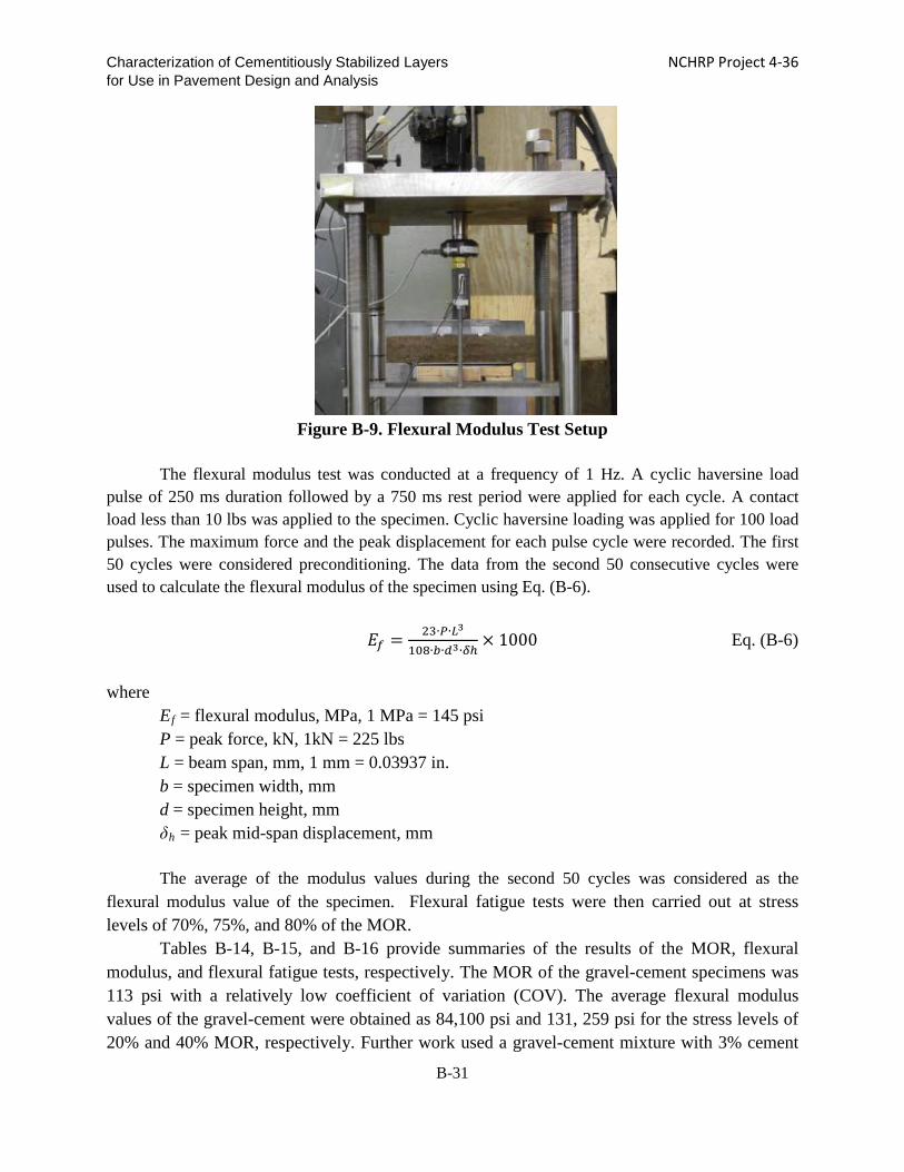
Characterization of Cementitiously Stabilized Layers NCHRP Project 4-36 for Use in Pavement Design and Analysis
Figure B-9. Flexural Modulus Test Setup
The flexural modulus test was conducted at a frequency of 1 Hz. A cyclic haversine load
pulse of 250 ms duration followed by a 750 ms rest period were applied for each cycle. A contact load less than 10 lbs was applied to the specimen. Cyclic haversine loading was applied for 100 load pulses. The maximum force and the peak displacement for each pulse cycle were recorded. The first 50 cycles were considered preconditioning. The data from the second 50 consecutive cycles were used to calculate the flexural modulus of the specimen using Eq. (B-6).
𝐸𝐸𝑓𝑓 = 23∙𝑃𝑃∙𝑃𝑃3
108∙𝑏𝑏∙𝜋𝜋3∙𝛿𝛿ℎ× 1000 Eq. (B-6)
where
Ef = flexural modulus, MPa, 1 MPa = 145 psi P = peak force, kN, 1kN = 225 lbs L = beam span, mm, 1 mm = 0.03937 in. b = specimen width, mm d = specimen height, mm δh = peak mid-span displacement, mm The average of the modulus values during the second 50 cycles was considered as the
flexural modulus value of the specimen. Flexural fatigue tests were then carried out at stress levels of 70%, 75%, and 80% of the MOR.
Tables B-14, B-15, and B-16 provide summaries of the results of the MOR, flexural modulus, and flexural fatigue tests, respectively. The MOR of the gravel-cement specimens was 113 psi with a relatively low coefficient of variation (COV). The average flexural modulus values of the gravel-cement were obtained as 84,100 psi and 131, 259 psi for the stress levels of 20% and 40% MOR, respectively. Further work used a gravel-cement mixture with 3% cement
B-31

Characterization of Cementitiously Stabilized Layers NCHRP Project 4-36 for Use in Pavement Design and Analysis
content. In order to observe the dependence of the modulus on the stress level, measurements were taken at stress levels of 20%, 30%, and 40 percent. The specimens were tested at the curing ages of 14 days and 28 days, respectively. Table B-17 presents the flexural test results. Similar to the earlier results, 20% stress level results in a lower flexural modulus when compared to those at 30% and 40% stress levels. The 30% and 40% stress levels yield comparable results. The 20% stress level is not recommended because the load level is low and the accuracy of the response is affected by the signal noise of the machine. Because the 40% stress level increases the potential for damage to the specimen, it is recommended that the flexural modulus test should be conducted at 30% stress level.
Figure B-10 shows a typical degradation of the flexural modulus during a beam fatigue test of the gravel-cement material. Based on the stress level, the flexural fatigue test was designed originally to observe failure near 10,000 cycles or three hours, based on the Austroads test protocol (Midgley and Yeo 2008). However, fatigue tests of the specimens performed at 70% stress continued for more than 20,000 cycles without failure and then were terminated. The results show that flexural fatigue behavior is highly sensitive to the level of stress. Even 5% change in stress level can significantly affect the number of cycles to failure. In addition, the fatigue test results are highly variable at each stress level, which has been reported by previous researchers (Midgley and Yeo 2008).
Figure B-10. Typical Degradation of Flexural Modulus in Fatigue Test of Gravel-Cement
Stress level: 75%
B-32

Characterization of Cementitiously Stabilized Layers NCHRP Project 4-36 for Use in Pavement Design and Analysis
Table B-14. Summary of MOR Test Results (Gravel-Cement 4%)
Test Item Specimen
No. MOR (psi)
Coefficient of Variation
(COV)
Modulus of rupture
GC-FS-1 123
113 7.59% GC-FS-2 112
GC-FS-3 106
Table B-15. Summary of Flexural Modulus Test Results (Gravel-Cement 4%)
Specimen No. Stress level by
percentage of MOR (%)
Flexural modulus (psi)
COV
GC-FM-20-1 20 76,705 84,100 10.84% GC-FM-20-2 20 81,200
GC-FM-20-3 20 94,250 GC-FM-40-1 40 121,365
131,225 8.81% GC-FM-40-2 40 128,470 GC-FM-40-3 40 143,985
Table B-16. Summary of Flexural Fatigue Test Results (Gravel-Cement 4%)
Test Item
Specimen No.
Stress Level (%)
Initial Flexural Modulus
(psi)
Flexural Modulus at End of Fatigue
Test (psi)
Percent Flexural Modulus at End of Fatigue
Test (%)
Number of Cycles at End of Fatigue
Test
COV of Fatigue
Life (%)
Note
Flexural Fatigue
GC-FT-70-1 70 147503 79336 48 28707 23.0%
Not yet failed GC-FT-70-2 70 157511 85137 54 20681 Not yet failed
GC-FT-75-1 75 130389 62656 48 389
103.2%
GC-FT-75-2 75 125748 44091 35 12895 GC-FT-75-3 75 146053 68603 47 1052 GC-FT-75-4 75 135030 40466 30 10898 GC-FT-80-1 80 177091 62801 35 3139
160.8%
GC-FT-80-2 80 143007 94275 66 58 GC-FT-80-3 80 173465 107618 62 99
B-33

Characterization of Cementitiously Stabilized Layers NCHRP Project 4-36 for Use in Pavement Design and Analysis
Table B-17. Summary of Flexural Test Results (Gravel-Cement 3%)
Specimen No. Stress Level (%)
Mixture: Gravel-Cement Binder Content: 3%
Curing: 14-day Standard
Mixture: Gravel-Cement Binder Content: 3%
Curing: 28-day Standard
Modulus of rupture: 86 psi Modulus of rupture: 106 psi
Flexural Modulus
(psi) Average (psi)
Flexural Modulus
(psi) Average (psi)
GC-FT-20-1 20
112,259 102,252
152,870 133,000
GC-FT-20-2 92,244 112,984 GC-FT-30-1
30 162,007
174,335 201,892
210,740 GC-FT-30-2 186,518 219,442 GC-FT-40-1
40 164,328
166,358 224,808
222,633 GC-FT-40-2 168,389 220,312
Tables B-18, B-19 and B-20 provide summaries of the flexural test results for the clay-
lime materials for the MOR, flexural modulus and flexural fatigue tests, respectively. The average MOR is 44 psi. The flexural modulus values are 65,847, 64,252, and 69,328 psi at stress levels of 20%, 30% and 40%, respectively. The clay-lime mixture shows more consistent flexural modulus results at the different stress levels than the gravel-cement mixture shows. In order to be consistent with the stress level for the flexural modulus of heavily stabilized materials, a stress level of 30% is recommended. For the fatigue tests, the stress levels range between 65% and 85%, as shown in Table B-20. The specimens tested at the stress level of 65% were still intact at the end of 100,000 cycles. Increasing the stress level significantly decreases the number of cycles to failure. The results indicate that the flexural modulus/fatigue test is a viable method for lightly stabilized materials as well, but has a relatively high variability as well. The flexural modulus and fatigue tests are recommended because they are the only tests available to simulate the bending of CSL in the field.
Table B-18. Summary of MOR Test Results (Clay-Lime 5%)
Test Item
Specimen No.
MOR (psi)
MOR CL-FS-1 46
44 CL-FS-2 41
B-34

Characterization of Cementitiously Stabilized Layers NCHRP Project 4-36 for Use in Pavement Design and Analysis
Table B-19. Summary of Flexural Modulus Test Results (Clay-Lime 5%)
Test Item Specimen No. Stress
Level (%) Flexural
Modulus (psi)
Flexural Modulus
CL-FM-20-1 20 49603 65847
CL-FM-20-2 20 82091
CL-FM-30-1 30 58595 64179
CL-FM-30-1 30 69763
CL-FM-40-1 40 65992 69328
CL-FM-40-2 40 72664
Table B-20. Summary of Flexural Fatigue Test Results (Clay-Lime 5%)
Test Item Specimen
No.
Stress Level (%)
Initial Flexural Modulus
(psi)
Flexural Modulus at End of Fatigue
Test (psi)
Percent Flexural
Modulus at End of Fatigue
Test (%)
Number of Cycles at
End of Fatigue Test
Note
Flexural Fatigue
CL-FT-65-1 65 75130 - - >100000 Not yet failed
CL-FT-65-2 65 43656 - - >100000 Not yet failed
CL-FT-75-1 75 71359 37275 52 1442
CL-FT-75-2 75 51343 26977 53 2726
CL-FT-85-1 85 - - - 3
CL-FT-85-2 85 62366 44382 71 621
Stress-Wave Base Modulus Test
The aim of the stress-wave base modulus test is to evaluate the effectiveness and reproducibility of the seismic modulus and ultrasonic pulse velocity tests as surrogate modulus tests. The evaluation of the seismic modulus test and ultrasonic pulse velocity test was performed on a gravel-cement mixture and a clay-lime mixture representing heavily stabilized and lightly stabilized soil systems, respectively. Prismatic specimens with dimensions of 4 in. × 4 in. × 4.5 in. were used for the gravel-cement mixture. The clay-lime mixture was molded to produce 4 in. (diameter) × 4.6 in. (height) cylindrical specimens. The testing age of the specimens was 28 days. Figure B-11 presents views of the test specimens.
B-35

Characterization of Cementitiously Stabilized Layers NCHRP Project 4-36 for Use in Pavement Design and Analysis
(a) Clay-Lime (b) Gravel-Cement
Figure B-11. View of Stress-Wave Base Modulus Test Specimens
(a) Impact Resonance Test Method The impact resonance test method is a simple and nondestructive test for determining the
modulus of pavement materials. The procedure allows the velocity of the elastic wave that propagates through a specimen to be measured. Depending on the dimensions and the stiffness of the specimen, the energy associated with one or more frequencies is trapped and magnified (resonated) as it propagates within the specimen. In the impact resonance method, a supported specimen is struck with a small impact device, and the specimen response is measured by a lightweight accelerometer on the specimen. Figure B-12 shows the free-free resonant column (FFRC) test setup used for this test method. Given the specimen’s mass density (ρ), travel time (t) and length (L), the seismic modulus (E) can be determined based on the p-wave velocity (Vp), as shown in Eq. (B-7).
E = ρ(L/t) 2 = ρ(Vp) 2 Eq. (B-7) where Vp is the wave velocity.
Figure B-12. Seismic Modulus Test Setup
B-36

Characterization of Cementitiously Stabilized Layers NCHRP Project 4-36 for Use in Pavement Design and Analysis
(b) Ultrasonic Test Setup An ultrasonic test instrument (Pundit Plus) that has a function to measure the elastic
modulus was evaluated. In this method, pulses of longitudinal stress waves are generated by an electro-acoustical transducer that is held in contact to one end surface of the specimen. After traversing through the specimen, the pulses are received and converted into electrical energy by the second transducer that is in contact with the opposite face of the specimen, as shown in Figure B-13. The ultrasonic tester readily determines the modulus of the specimen based on travel time, path length travelled, and density of the CSM.
Figure B-13. View of the Ultrasonic Test Setup
Ten measurements were taken for each of the seismic tests and ultrasonic tests. This
study reveals statistically significant differences and poor reproducibility in the results obtained using the FFRC test setup. The significance of difference in the results is obviously higher for the gravel-cement specimens, as shown in Figure B-14. The seismic modulus values obtained from the FFRC test range between 1,000 ksi and 7,000 ksi for one material, whereas the constrained modulus values determined by the ultrasonic test setup range between 3,000 ksi and 3,800 ksi for gravel-cement. As shown in Figure B-15, the seismic modulus values obtained from the FFRC test range between 900 ksi and 1,600 ksi for the clay-lime specimens, whereas the constrained modulus values determined by the ultrasonic test are again quite consistent, ranging between 500 ksi and 600 ksi. Thus, the ultrasonic pulse velocity test can provide more repeatable results than the FFRC test.
However, the moisture content of CSM can affect the results of the ultrasonic test method, which is also reported by Fratta et al. (2005) and shown in Figure B-16. The p-wave velocity decreases with increasing saturation and becomes nearly constant for a range of degrees of saturation. When the saturation level is close to 100% (i.e. after prolonged soaking), the constrained modulus value becomes very high, which indicates that the p-wave traveling through the water phase. After increasing the moisture content by long-time soaking, the measured
B-37

Characterization of Cementitiously Stabilized Layers NCHRP Project 4-36 for Use in Pavement Design and Analysis
constrained modulus increases for all four types of mixtures, as shown in Figure B-17. Therefore, this study concludes that the FFRC and ultrasonic tests are not suitable for determining the modulus of CSM.
Figure B-14. Variation in Modulus Results Obtained from Seismic and Ultrasonic Tests for
Gravel-Cement Specimens
Figure B-15. Variation in Modulus Results Obtained from Seismic and Ultrasonic Tests for
Clay-Lime Specimens
B-38

Characterization of Cementitiously Stabilized Layers NCHRP Project 4-36 for Use in Pavement Design and Analysis
Figure B-16. Effect of Saturation on P-wave Velocity (Fratta et al. 2005)
(a) Gravel-Cement
-2%
-1%
0%
1%
2%
3%
4%
5%
2000
2100
2200
2300
2400
2500
2600
2700
0 1 2 3 4 5 6 7 8 9 10 11
moi
stur
e co
nten
t cha
nge
(%)
Con
stra
ined
Mod
ulus
(ksi
)
Soaking time (hrs)
Gravel-Cement
Constrained Modulus
Moisturecontentchange
24
B-39
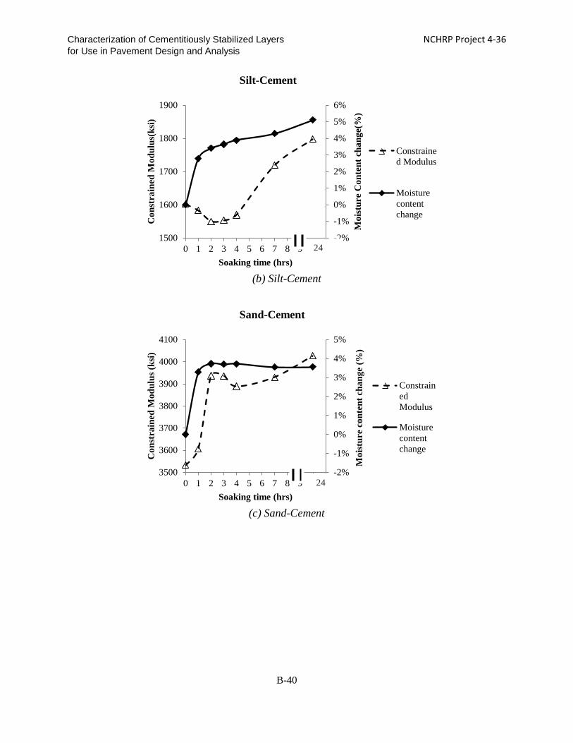
Characterization of Cementitiously Stabilized Layers NCHRP Project 4-36 for Use in Pavement Design and Analysis
(b) Silt-Cement
(c) Sand-Cement
-2%
-1%
0%
1%
2%
3%
4%
5%
6%
1500
1600
1700
1800
1900
0 1 2 3 4 5 6 7 8 9 10 11
Moi
stur
e C
onte
nt c
hang
e(%
)
Con
stra
ined
Mod
ulus
(ksi
)
Soaking time (hrs)
Silt-Cement
Constrained Modulus
Moisturecontentchange
24
-2%
-1%
0%
1%
2%
3%
4%
5%
3500
3600
3700
3800
3900
4000
4100
0 1 2 3 4 5 6 7 8 9 10 11
Moi
stur
e co
nten
t cha
nge
(%)
Con
stra
ined
Mod
ulus
(ksi
)
Soaking time (hrs)
Sand-Cement
ConstrainedModulus
Moisturecontentchange
24
B-40

Characterization of Cementitiously Stabilized Layers NCHRP Project 4-36 for Use in Pavement Design and Analysis
(d) Sand-C Fly Ash
Figure B-17. Effect of Moisture Content on Constrained Modulus
Durability Tests
The objective of the durability test evaluation is to investigate whether durability tests are applicable to CSM, especially for lightly stabilized materials. Wet-Dry Durability Test
For the wet-dry tests, C fly ash-gravel and lime-clay were selected to represent materials
with strength values from high to low. After curing at 104°F and 100% RH for 5 days, the specimens in a test group were subjected to wet-dry cycles: i.e., they were soaked in water for 4 hours at 68°F and dried in an oven at 158°F for 42 hours, in accordance with ASTM D559-03. Specimens in the control group were wrapped with a moist towel and subjected to the same temperature cycles (4 hours at 68°F and 42 hours at 158°F), which served to eliminate the effect of temperature on the CSM, leaving moisture as the only effective factor. The specimens were tested for UCS after different wet-dry cycles. Each material had 3 replicates.
Table B-21 presents the UCS test results where it is seen that after 13 wet-dry cycles, the UCS of the C fly ash-gravel dropped from 1223 psi to 1024 psi, whereas the UCS of the lime-clay specimens decreased from 373 psi to 241 psi after 9 wet-dry cycles, which is only 65% of their initial strength values. The Class C fly ash-gravel retained 84% strength of the control group. This wet-dry durability test is recommended for both lightly stabilized materials and heavily stabilized materials.
-4%
-2%
0%
2%
4%
6%
8%
1650
1750
1850
1950
2050
2150
0 1 2 3 4 5 6 7 8 9 10 11
Moi
stur
e C
onte
nt C
hang
e (%
)
Con
stra
ined
Mod
ulus
(ksi
)
Soaking time (hrs)
Sand-C Fly ash
ConstrainedModulus
Moisturecontentchange
24
B-41

Characterization of Cementitiously Stabilized Layers NCHRP Project 4-36 for Use in Pavement Design and Analysis
Table B-21. Wet-Dry Test Results
Specimen No. of Cycles
UCS Values for Wet-Dry Cycles (psi) UCS of Control
Group (psi)
Residual Rate (%) Specimen
1 Specimen
2 Specimen
3 Average COV
C Fly Ash-Gravel 13 984 1014 1074 1024 4% 1223 84
Lime-Clay 9 256 226 242 241 6% 373 65 Freeze-Thaw Durability Test
Freeze-thaw tests were conducted to develop freeze-thaw durability models. These tests
used two mixtures in gravel-cement and clay-lime specimens. The specimens were molded to produce 4 in. (diameter) by 4.6 in. (height) cylindrical specimens. The gravel-cement specimens were cured in a moist room at 100% RH and 70°F for 28 days in accordance with ASTM D558. The clay-lime specimens were sealed with plastic wrap and cured for 7 days in an oven at 104°F. After curing, the specimens were placed on top of a water-absorbing pad in the freezing apparatus with temperatures below -10°F for 24 hours following ASTM D560. After the freezing stage, the specimens were placed in a moist room at 70°F and 100% RH for 23 hours. The UCS values of the specimens in the control group were measured after curing. The UCS values of the specimens in the freeze-thaw group were measured after the freeze-thaw cycles. Table B-22 presents the UCS results for the freeze-thaw tests where it is seen that after two freeze-thaw cycles, the UCS of the cement-gravel dropped from 638 psi to 444 psi, whereas the UCS of the lime-clay specimens decreased from 149 psi to 57 psi. Based on the residual rate, the residual strength of the lime-clay was only 38% of its initial strength, whereas the cement-gravel had a residual rate of about 70 percent. Therefore, the lime-clay material experienced more damage during the freeze-thaw cycles than the cement-gravel material. The test results indicate that the freeze-thaw durability test is applicable to both lightly stabilized materials and heavily stabilized materials.
Table B-22. Freeze-Thaw Test Results
UCS Values for 2 Freeze-Thaw Cycles (psi) UCS of Control
Group (psi)
Residual Rate (%) Specimen Specimen
1 Specimen
2 Specimen
3 Average COV
Cement-Gravel 535 419 377 444 18% 638 70 Lime-Clay 62 57 52 57 9% 149 38
Vacuum Saturation Test
The effects of vacuum saturation on the UCS of gravel-cement and clay-lime specimens
also were studied. Six gravel-cement and six clay-lime specimens were fabricated and cured in a moist room (100% RH). The gravel-cement specimens were cured at 68°F, and the clay-lime specimens were cured at 104°F. After curing for 7 days, 3 specimens were tested for UCS, and the remaining 3 specimens were vacuum-saturated and then tested for UCS.
B-42

Characterization of Cementitiously Stabilized Layers NCHRP Project 4-36 for Use in Pavement Design and Analysis
The vacuum saturation strength tests were carried out according to ASTM C593, Standard Specification for Fly Ash and Other Pozzolans for Use with Lime for Soil Stabilization, except the vacuum process was modified. The specimens were sealed and vacuumed to a pressure of 29 in-Hg (14.24 psi) using a CoreLok device and submerged in water. The vacuum-sealed bags were cut open in the water and the specimens were removed and left in the water for half an hour. Figure B-18 shows a vacuum-sealed specimen.
Figure B-18. Vacuum Test Setup
Table B-23 shows the UCS results of unsaturated and vacuum-saturated gravel-cement
specimens, which are also shown in Figure B-19. The average UCS value for the control group is 1,074 psi, whereas the average UCS value after vacuum saturation is 957 psi. Vacuum saturation slightly reduces the UCS of gravel-cement.
Table B-23. Test Results of Vacuum Saturation for Gravel-Cement Specimens
UCS, Unsaturated UCS, Vacuum Saturated
Specimen No. psi COV Specimen
No. psi COV
1 1,041 4.39%
4 992 13.53% 2 1,053 5 1,066
3 1,128 6 814 Average 1,074 Average 957
B-43

Characterization of Cementitiously Stabilized Layers NCHRP Project 4-36 for Use in Pavement Design and Analysis
Figure B-19. UCS with and without Vacuum Saturation for Gravel-Cement
For the clay-lime specimens, vacuum saturation decreases the UCS by 55%, from 115 psi
to 52 psi, as shown in Table B-24 and Figure B-20. Based on the test results, it appears that the vacuum saturation test method is applicable to both lightly and heavily stabilized materials to reduce their strength.
However, one significant shortcoming of vacuum saturation is that it provides only a qualitative evaluation of the durability of CSM. The effect of the number of freeze-thaw cycles on CSM cannot be quantified. Therefore, vacuum saturation is not recommended for model development.
Table B-24. Test Results of Vacuum Saturation for Clay-Lime Specimens
UCS, Unsaturated UCS, Vacuum Saturated
Specimen No. psi COV Specimen
No. psi COV
1 105 7.72%
4 54 12.72% 2 122 5 45
3 118 6 58 Average 115 Average 52
0
200
400
600
800
1000
1200
Unsaturated Vacuum Saturated
UC
S (p
si)
Saturation Condition
Effect of Vacuum Saturation on UCS (Gravel-Cement)
1
2
3
B-44

Characterization of Cementitiously Stabilized Layers NCHRP Project 4-36 for Use in Pavement Design and Analysis
Figure B-20. UCS of Unsaturated and Saturated Specimens
Large-Scale Model Experiment (LSME)
The objective of this phase of the investigation is to identify a procedure for determining the number of load cycles to fatigue crack initiation for a cement-stabilized base course and subgrade materials using the large-scale model experiment (LSME). This procedure is intended to determine whether the fatigue model that is developed based on small-scale laboratory beam fatigue tests can be calibrated.
Cement-stabilized gravel, recycled pavement materials (as part of procedure development for another study), and silt were used to evaluate the applicability of the LSME. Mixing the materials was accomplished using a Gilson portable concrete mixer in 220-lb batches. The appropriate mass of the cement was added to the soil under air-dry conditions and allowed to mix for at least two minutes. Water was added slowly until the batch was evenly coated and brought to nearly optimal water content for the mixture. After mixing for approximately five minutes, the mixture was shoveled into the test pit. Additional batches were created in the same manner until enough material that could be compacted in a single lift was placed. A jumping-jack style compactor and hand tamper were used to compact the stabilized layer to the desired thickness at the maximum dry unit weight. Specimens were covered with plastic and allowed to cure under ambient laboratory conditions.
The LSME was conducted in a 10 ft × 10 ft × 10 ft test pit. The bottom 8.2 ft of the test pit was filled with dense, uniformly graded subgrade sand. The test materials were placed on top of the subgrade sand to the desired thickness. Loads were generated using a MTS 280 L/m hydraulic actuator with a 20-kip load capacity and 6.6 in. stroke supported by a steel load frame. Applied loads were transferred to the pavement profile using a 1-inch thick steel plate with a radius of 4.9 inches. The MTS equipment is capable of applying a haversine-shaped load pulse over a range of load durations, load levels and rest periods. Vertical deflections of the pavement
0
20
40
60
80
100
120
140
Unsaturated Vacuum Saturated
UC
S (p
si)
Saturation Condition
Effect of Vacuum Saturation on UCS (Clay-Lime)
B-45

Characterization of Cementitiously Stabilized Layers NCHRP Project 4-36 for Use in Pavement Design and Analysis
profile were measured using LVDTs with a precision of +/- 0.0002 inch. Surface deflections were measured using an LVDT mounted on the surface of the loading plate. The steel plate was assumed to be rigid and, thus, any movement of the plate was translated to the pavement section. Subgrade deflections were measured by attaching two small plates at either end of a thin rod. One plate was placed flush at the subgrade surface beneath the load plate. The thin rod was passed through a tube extending through the stabilized layer, allowing the rod to move freely with the subgrade. The second plate was positioned above the stabilized layer surface where another LVDT was mounted. Deflections and applied load data were collected using LabView 7.1 software. Figure B-21 shows a schematic view of the LSME. While the tests were running, the specimen surface was visually inspected for the presence of cracks.
Previous LSMEs have used the entire 10 ft × 10 ft section to evaluate pavement profiles (Tanyu et al. 2003, Kootstra 2009), whereas other experiments have used a smaller 3.3 ft × 3.3 ft section (Schaertl 2010). Using the entire test pit section would require a significantly large amount of material. Thus, test trials have been initiated using specimens that utilize the same setup as found in Schaertl (2010) with dimensions approximately 3.3 ft × 3.3 ft and 8 in. thick. With the absence of an asphalt layer, a force of 1,500 lbs was applied using a 4.9-inch steel load plate to simulate truck traffic (Kootstra 2009, Schaertl 2010). Based on the results of the MICHPAVE program, the applied force was determined to be equivalent to a 15.7 kip axle load with 101.5 psi tire pressure when an asphalt layer is present.
Figure B-21. Schematic of LSME Setup, 1 m = 3.3 ft (Schaertl 2010)
The initial LSME tests employed a silt-cement (4% by weight) slab approximately 3.3 ft
× 3.3 ft and 8 in. thick. Surface and subgrade deflections were measured, and the specimens were monitored for fatigue cracking. The tests were conducted during the day in increments of 20,000 to 40,000 cycles. Cracking was not observed after 325,000 cycles at loads ranging from 2,500 to
B-46

Characterization of Cementitiously Stabilized Layers NCHRP Project 4-36 for Use in Pavement Design and Analysis
7,000 lbs. A second silt-cement specimen of the same geometry was tested next. In order to increase deflections during loading and thus increase the stress/strain in the layer, a 3.3 ft × 3.3 ft piece of 2-inch thick extruded polystyrene (XPS) was placed beneath the specimen. The presence of the foam layer doubled the elastic deflections compared to the first test. No cracking was observed after 140,000 cycles at 4,000 lbs and 260,000 cycles at 5,000 lbs.
Observations of the specimen movement indicate that the silt-cement was likely compressed with little flexural response, which appears to be due to the relatively small size of the specimen compared to the steel load plate. Therefore, the specimen size was increased to a 3.3 ft × 6.6 ft test section. Additionally, the CSL slab and foam layer thicknesses were reduced to 4 in. and 1 in., respectively. The foam layer was centered beneath the specimen and remained at 3.3 ft × 3.3 ft., effectively leaving 1.6 ft at each end of the specimen supported on the subgrade sand. The intent was to simulate a simply supported lab scale beam specimen in the LSME test pit and to induce flexure.
Recycled pavement material was stabilized with 3% cement by weight and set up using the new configuration. The applied load ranged from 3,500 to 6,000 lbs. Loading commenced at 3,500 lbs for 100,000 cycles. With no observed cracking, the load was subsequently increased to 4,000, 5,000, and 5,500 lbs each for 200,000 cycles. Still no cracking was observed. After about 179,000 cycles (879,000 cycles in total) at 6,000 lbs, a fatigue crack was observed on the recycled pavement material surface approximately 14 in. to the left of the steel load plate. The crack ran perpendicular to the length of the specimen and made nearly imperceptible movements during each load application. However, deflection data gave no clear indication of the exact time of the crack initiation (Figure B-22). The elastic deflection around this time was about 0.0358 inch. Just prior to the observation of cracking, a slight increase in the surface elastic measurement was observed, up from 0.0354 in. and, afterward, deflections grew to exceed 0.0362 inch. This change is extremely small.
Figure B-22. Elastic Deflections of Recycled Pavement Material before and after Crack
Observation (25.4 mm = 1 in.)
0.86
0.88
0.90
0.92
0.94
0.96
0.98
1.00
850000 860000 870000 880000 890000 900000
Mea
sure
d D
efle
ctio
n (m
m)
Cycle
Surface Elastic
SurfaceElastic
B-47

Characterization of Cementitiously Stabilized Layers NCHRP Project 4-36 for Use in Pavement Design and Analysis
Another specimen composed of gravel and cement (3% by weight) was set up in the same
configuration as the recycled pavement material -cement specimens. The applied load was set to 6,000 lbs at the beginning of the test. Two fatigue cracks, each 14 in. to the right and left of the steel load plate, were observed on the gravel surface in less than 5,000 cycles (Figure B-23). Like the recycled pavement material test results, the deflection data for the gravel-cement specimens appear to be unchanged by the presence of these cracks, as shown in Figure B-24. Most of the plastic strain accumulation occurred during the first 1000 cycles, after which the strain rate became relatively constant. The elastic deflections tended to decrease slowly during the test as the material became more densely compacted under loading.
Figure B-23. Observed Crack on Gravel-Cement Surface
Figure B-24. Measured Deflections for Gravel-Cement with Foam at 6000 lbs
0
0.5
1
1.5
2
2.5
3
3.5
4
4.5
0 2000 4000 6000 8000
Mea
sure
d D
efle
ctio
n (m
m)
Cycles
Surface Total
Surface Plastic
B-48

Characterization of Cementitiously Stabilized Layers NCHRP Project 4-36 for Use in Pavement Design and Analysis
The soil was changed to silt for the next tests because the gravel-cement specimens proved difficult for observing fatigue cracks due to the rough surface. Also, the deflection data yielded no clear signs of cracking. Three silt-cement slabs, each 3.3 ft × 6.6 ft and 4 in. thick, were placed on an expanded polystyrene (EPS) support. The EPS support was manufactured by Cellofoam and typically has a density of 1 pund per cubic foot (pcf). Tanyu et al. (2003) note that the stress-strain behavior of a low-density (1.1 pcf) EPS support is comparable to Antigo silt loam, a typical soft subgrade soil found in Wisconsin. The first silt-cement slab cracked in less than 200 cycles at 1,500 lbs. This load level seems to be too extreme due to the soft EPS support. For the second specimen, the applied load was reduced to 900 lbs, and a crack was observed after about 3,000 cycles (Figure B-25). For both tests, the cracks were located near the center of the CSL. The third specimen was subjected to a load of 750 lbs. Small cracks (1 in. long) were observed after 1,500 cycles. The cracks continued to grow and connect to additional observed cracks. After 16,000 cycles, the cracks appeared to be forming a ring around the steel load plate. As with all the previous LSME tests where cracking was observed, the deflection data provided no indications of the exact time of crack initiation.
Figure B-25. Observed Crack in Silt-Cement Surface
The resilient deformation of CSL was not affected by the occurrence of fatigue cracking
in the LSME. Changes in the deflection characteristics were expected to manifest during or after cracking of the stabilized materials. However, for all tests where cracking was observed, the presence of cracking did not appear to impact the measured deflections. Numerical modeling indicates that the deflection change due to cracking is very small, supporting the observations. The location of the cracks varied for each LSME test, which suggests that the fatigue behavior of the CSL is not controlled by the stress condition alone. By nature, CSL are not homogeneous and are susceptible to material defects. Therefore, cracking may not occur at the point of maximum stress within the CSL but at local weak points. The results from the LSME study indicate that
B-49

Characterization of Cementitiously Stabilized Layers NCHRP Project 4-36 for Use in Pavement Design and Analysis
this LSME fatigue test is able to characterize the fatigue behavior of CSM. For instance, increasing the load reduces the fatigue life (based on observations of the surface, not the reduction of the modulus), and an increase in the thickness of the slab prolongs the fatigue life of the CSM. However, the resilient strain and causal modulus of the CSL remain unaffected by the occurrence of cracks, which contradicts to the field observation. Therefore, the LSME is not recommended for fatigue model calibration. Shrinkage and Cracking
The objective of the shrinkage test evaluation is to investigate the test methods that are input factors for the shrinkage strain and shrinkage cracking models. Coefficient of Thermal Expansion (COTE) Test
The coefficient of thermal expansion (COTE) is a key parameter in the shrinkage
cracking model. The originally proposed test method for the COTE of concrete, based on AASHTO TP60, Standard Method of Test for Coefficient of Thermal Expansion of Hydraulic Cement Concrete, is not suitable for measuring the COTE of lightly stabilized materials or the early-age (e.g., 2 days) COTE of heavily stabilized materials which is critical for early-age shrinkage cracking. The saturation method recommended in AASHTO TP60 would severely damage the lightly stabilized materials or the early-age specimens of heavily stabilized materials. In addition, thermal expansion is coupled with autogeneous and drying shrinkage for early-age stabilized materials. A test method for COTE, recommended by Cusson and Hoogeveen (2006), which was specifically designed for early-age concrete, is evaluated in this study based on temperature cycling. The shrinkage of a CSL specimen includes autogenous, drying, and thermal shrinkage. The use of temperature cycling can separate the thermal shrinkage/expansion from autogenous and drying shrinkage.
Prism specimens with dimensions of 4 in. × 4 in. × 11.25 in. were placed in an environmental chamber at an initial ambient temperature of 77°F and 98% RH. The chamber cycled the temperature between 77°F and 86°F using a saw-tooth pattern while the RH was kept constant. After the target temperature in the chamber was reached, which takes about 20 minutes, the temperature was kept constant for 4 hours, resulting in three full cycles (or six steps) per day. The constant temperature period is long enough to ensure a stable and uniformly distributed temperature in the prism sample. The amplitude of the temperature cycle (9°F) is selected to be small enough to maximize the number of cycles per day and obtain more COTE values at early ages. With such small temperature changes, the temperature effect on the change in COTE over time can be considered small (Cusson and Hoogeveen 2006).
The displacements were measured by LVDTs. The temperatures inside the specimens and environmental chamber were monitored by thermal couples.
B-50

Characterization of Cementitiously Stabilized Layers NCHRP Project 4-36 for Use in Pavement Design and Analysis
Figures B-26 and B-27 show the test results and COTE of the clay-lime and gravel-cement specimens, respectively. The COTE of the clay-lime specimens increased within the first two days and then stabilized at about 4.7×10⁻⁵/°F. However, the COTE of the gravel-cement samples was relatively stable at about 1.4×10⁻⁵/°F, which is about one-third of that of the clay-lime specimens.
Figure B-26. COTE Development of Clay-Lime Specimens
Figure B-27. COTE Development of Gravel-Cement Specimens
Overall, the COTE test, which is based on temperature cycling, is capable of measuring
the COTE of both lightly and heavily stabilized materials and is recommended for model development.
0.0E+00
1.0E-05
2.0E-05
3.0E-05
4.0E-05
5.0E-05
6.0E-05
7.0E-05
0 50 100 150
CO
TE
(/°F
)
Time (hours)
COTE-Time (Clay-Lime)
Specimen 1 (77-86°F)
Specimen 2 (77-86°F)
Specimen 3 (77-86°F)
0.0E+00
3.0E-06
6.0E-06
9.0E-06
1.2E-05
1.5E-05
1.8E-05
0 50 100 150
CO
TE
(/°F
)
Time (hours)
COTE-Time (Gravel-Cement)
Specimen 1 (77-86°F)
Specimen 2 (77-86°F)
Specimen 3 (77-86°F)
B-51

Characterization of Cementitiously Stabilized Layers NCHRP Project 4-36 for Use in Pavement Design and Analysis
Bond Strength Test
Bond strength is an input to the restrained shrinkage cracking model. Because the beam
specimen for restrained shrinkage cracking is glued onto a steel substrate with epoxy or cement mortar, the bond strength between the CSM and steel substrate is measured when epoxy or cement mortar are used as bonding agents.
The bond strength tests were conducted in accordance with the Iowa shear test (Iowa DOT 2000), which separates the CSL and base along the interface. Two materials, i.e., clay-lime and gravel-cement, were used and compacted at the optimum moisture content. The mixed materials were compacted by standard Proctor compaction in a 4-inch diameter mold. The specimens were cured at 100% RH at room temperature (68°F) for 7 days and were glued to a steel substrate with epoxy or cement mortar. The cement mortar was prepared with a sand:cement:water ratio of 6:2:2.
The bond strength tests were conducted at a constant loading rate (71.6 psi/min) or constant deformation rate (0.065 in./min). Figures B-28 and B-29 show the test results for the constant loading rate and constant deformation rate for the cement-gravel specimens, respectively. Due to abrupt failure during the constant loading rate tests, a constant deformation rate is recommended for the purpose of safety. However, the repeatability of the deformation control (0.065 in./min) is poor. Thus, the load speed was increased to 0.65 in./min, which improved the repeatability.
Figure B-28. Bond Strength under Constant Loading Rate for Cement-Gravel (71.6 psi/min)
0.0E+00
3.0E+02
6.0E+02
9.0E+02
1.2E+03
1.5E+03
0.00 0.02 0.04 0.06 0.08 0.10
Loa
d (lb
s)
Time (s)
B-52

Characterization of Cementitiously Stabilized Layers NCHRP Project 4-36 for Use in Pavement Design and Analysis
Figure B-29. Bond Strength under Constant Deformation Rate for Cement-Gravel (0.065
in./min)
Table B-25 and Figures B-30 and B-31 present the test results for three clay-lime and three gravel-cement specimens that use epoxy or cement mortar as bonding agents, respectively. Some variability is seen in the bond strength measured. As shown in Figure B-30, when cement mortar is used as the bonding agent, the bond strength values for the clay-lime and gravel-cement specimens are very close to each other, around 3 psi, because the failure occurred within the mortar. That is, the bond strength was controlled by the strength of the cement mortar. Therefore, the clay-lime and gravel-cement specimens have similar bond strength values when cement mortar is used as the bonding agent.
When epoxy is used as the bonding agent, the bond strength values of the clay-lime specimens are significantly lower than those of the gravel-cement specimens, as shown in Figure B-31. Shear failure occurred inside the clay-lime specimen, as shown in Figure B-32 (a). Therefore, the bond strength that was measured is actually the shear strength of the clay-lime. The failure plane for the gravel-cement specimen is located at the interface between the epoxy and soil specimen in Figure B-32 (b). Therefore, this measured strength is the bond strength at the interface.
0.0E+00
2.0E+02
4.0E+02
6.0E+02
8.0E+02
1.0E+03
0.00 0.02 0.04 0.06 0.08 0.10
Loa
d (lb
s)
Time (s)
B-53

Characterization of Cementitiously Stabilized Layers NCHRP Project 4-36 for Use in Pavement Design and Analysis
Table B-25. Results of Bond Strength Tests Binder Materials Shear Strength (psi) COV
Mortar
Clay-Lime 2.53
26.2% 2.43 3.80
Gravel-Cement 2.68
27.9% 2.57 4.14
Epoxy
Clay-Lime 19.1
32.1% 14.0 26.8
Gravel-Cement 206.8
10.5% 224.5 181.8
Figure B-30. Bond Strength Test when Cement Mortar is used as Bonding Agent
0.0
0.5
1.0
1.5
2.0
2.5
3.0
3.5
4.0
4.5
Clay-Lime Gravel-Cement
Bon
d st
reng
th (p
si)
Specimen 1
Specimen 2
Specimen 3
B-54

Characterization of Cementitiously Stabilized Layers NCHRP Project 4-36 for Use in Pavement Design and Analysis
Figure B-31. Bond Strength Test when Epoxy is used as Bonding Agent
(a) Clay-Lime Specimen after Test (b) Gravel-Cement Specimen after Test
Figure B-32. Failure Surfaces after Bond Strength Tests
Even though some variability was found between the bond strength of the replicates, the Iowa shear test is capable of measuring the bond strength for modeling shrinkage cracking and is recommended for model development.
Free Autogenous Shrinkage
Autogenous shrinkage is the shrinkage due to hydration of the binder in CSL.
Autogenous shrinkage can be measured when specimens are wrapped with plastic to prevent loss of moisture. However, it is cumbersome to wrap specimens with plastic and difficult to prevent
0
50
100
150
200
250
Clay-Lime Gravel-Cement
Bon
d st
reng
th (p
si)
Bond strength test when EPOXY as binding materials
Specimen 1
Specimen 2
Specimen 3
B-55

Characterization of Cementitiously Stabilized Layers NCHRP Project 4-36 for Use in Pavement Design and Analysis
moisture loss and drying shrinkage. Instead, wax was used in this study to seal the specimens. Specimens of clay-lime and gravel-cement were fabricated and placed in plaster molds, as shown in Figure B-33. Hot liquid wax was poured into each plaster mold. After the excess liquid wax was drained, the specimen was covered with a thin layer of wax. The plaster mold was removed and the specimens and wax were cooled to room temperature. A plastic pad was glued onto the sides of the specimen in order to prevent permanent deformation caused by the tips of the dial gauges. The shrinkage was then measured, as shown in Figure B-34.
Figure B-33. Plaster Mold
Figure B-34. Autogenous Shrinkage Test Setup
Figure B-35 shows the free autogenous shrinkage test results. The clay-lime specimens show large autogenous shrinkage, which continued to increase even after 8 days; whereas the
B-56

Characterization of Cementitiously Stabilized Layers NCHRP Project 4-36 for Use in Pavement Design and Analysis
autogenous shrinkage of gravel-cement specimens was small and stabilized after about 3 days. This phenomenon might be due to the fact that the reaction time for the clay-lime is longer than for the gravel-cement mixture.
Figure B-35. Autogenous Shrinkage Results of Clay-Lime and Gravel-Cement Specimens
Based on the test results, it seems that the autogenous shrinkage of CSL can be measured
using this test. Free Drying Shrinkage
This test aims to measure free drying shrinkage due to moisture loss. Free drying
shrinkage tests were conducted on both lightly stabilized materials (clay-lime) and heavily stabilized materials (gravel-cement). For measuring the drying shrinkage, clay-lime and gravel-cement specimens were fabricated with dimensions of 4 in. × 4 in. × 11.25 in., as shown in Figure B-36. The specimens were air-dried and the displacements were measured from both ends. Two dial gauges were placed on the ends to measure the displacements. The total shrinkage strain is the sum of the two measured strains. The drying shrinkage strain is equal to the total shrinkage strain minus the autogenous shrinkage strain, because the specimen is simultaneously subjected to autogenous shrinkage as well.
Each specimen was placed on a solid plate and lubricant was applied between the specimen and solid plate to allow free movement of the specimen. In addition, in order to allow the specimen to dry in 3 dimensions (6 surfaces), another specimen was placed on a metal plate with numerous small holes for moisture to evaporate from the bottom as well. Lubricant was applied between the specimen and metal plate to allow free movement of specimen. The third method that was evaluated in this study was to reduce the height of specimen (for fine-grained materials only) to mitigate the effect of the moisture gradient inside the specimen, without the need for the metal plate with holes. A 2-inch high specimen was used. The shrinkage of the three
-8.0E-04
-7.0E-04
-6.0E-04
-5.0E-04
-4.0E-04
-3.0E-04
-2.0E-04
-1.0E-04
0.0E+000 50 100 150 200
Stra
in
Time (hr)
Clay-Lime 1
Clay-Lime 2
Clay-Lime 3
Gravel-Cement 1
Gravel-Cement 2
Gravel-Cement 3
B-57

Characterization of Cementitiously Stabilized Layers NCHRP Project 4-36 for Use in Pavement Design and Analysis
specimens was measured side by side, as shown in Figure B-37. Figure B-38 shows the test results and indicates that the shrinkage of these three specimens is very similar to each other. Therefore, the effect of specimen dimension and evaporation from the bottom of the specimen is negligible. It is recommended that the drying shrinkage test should be conducted on specimens with dimensions of 4 in. × 4 in. × 11.25 in. on a solid plate and that lubricant should be applied between the specimen and plate.
Figure B-36. Compaction Mold for Free Shrinkage Test
Figure B-37. Test Setup to Evaluate the Effects of Specimen Dimension and Bottom
Surface (left: 4 in. high on porous plate; middle: 4 in. high on solid plate; right: 2 in. high on solid
plate)
B-58

Characterization of Cementitiously Stabilized Layers NCHRP Project 4-36 for Use in Pavement Design and Analysis
Figure B-38. Effects of Specimen Dimension and Bottom Surface
Lime-stabilized clay and cement-stabilized gravel specimens were fabricated, as shown
in Figure B-39. Figure B-40 presents the test results and indicates that the results for lime-stabilized clay are very close and repeatable compared to those of cement-stabilized gravel. The shrinkage of lime-stabilized clay continued to increase, whereas the shrinkage of the cement-stabilized gravel stabilized after three days.
(a) Clay-Lime (b) Gravel-Cement
Figure B-39. Drying Shrinkage Test
-3.0E-03
-2.5E-03
-2.0E-03
-1.5E-03
-1.0E-03
-5.0E-04
0.0E+000 10 20 30 40 50
Stra
in
Time (hr)
4" on porous plate
4" on solid plate
2" on solid plate
B-59
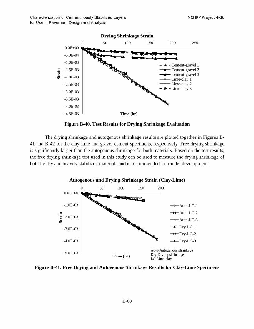
Characterization of Cementitiously Stabilized Layers NCHRP Project 4-36 for Use in Pavement Design and Analysis
Figure B-40. Test Results for Drying Shrinkage Evaluation
The drying shrinkage and autogenous shrinkage results are plotted together in Figures B-
41 and B-42 for the clay-lime and gravel-cement specimens, respectively. Free drying shrinkage is significantly larger than the autogenous shrinkage for both materials. Based on the test results, the free drying shrinkage test used in this study can be used to measure the drying shrinkage of both lightly and heavily stabilized materials and is recommended for model development.
Figure B-41. Free Drying and Autogenous Shrinkage Results for Clay-Lime Specimens
-4.5E-03
-4.0E-03
-3.5E-03
-3.0E-03
-2.5E-03
-2.0E-03
-1.5E-03
-1.0E-03
-5.0E-04
0.0E+000 50 100 150 200 250
Stra
in
Time (hr)
Drying Shrinkage Strain
Cement-gravel 1Cement-gravel 2Cement-gravel 3Lime-clay 1Lime-clay 2Lime-clay 3
-5.0E-03
-4.0E-03
-3.0E-03
-2.0E-03
-1.0E-03
0.0E+000 50 100 150 200
Stra
in
Time (hr)
Autogenous and Drying Shrinkage Strain (Clay-Lime)
Auto-LC-1
Auto-LC-2
Auto-LC-3
Dry-LC-1
Dry-LC-2
Dry-LC-3
Auto-Autogenous shrinkage Dry-Drying shrinkage LC-Lime clay
B-60

Characterization of Cementitiously Stabilized Layers NCHRP Project 4-36 for Use in Pavement Design and Analysis
Figure B-42. Free Drying and Autogenous Shrinkage Results for Gravel-Cement
Specimens
Restrained Drying Shrinkage Cracking
Tensile stress is produced when moisture or temperature changes cause the CSL base or subbase to contract or shrink with restraint. Shrinkage cracking occurs when the tensile stress exceeds the tensile strength of the cement-treated pavement layer (Cauley and Kennedy 1972). Because shrinkage cracking occurs when the CSL are restrained, the shrinkage cracking potential of each CSL material can be examined using the restrained shrinkage cracking test. The increase in friction between the CSL and underlying material reduces the shrinkage crack spacing. By artificially creating a high level of bond, shrinkage cracking can be generated in a laboratory-scale specimen for model development. The CSL slab is bonded to a steel tube to prevent curling.
Clay-lime and gravel-cement beams with dimensions of 48 in. × 6 in. × 4 in. were glued onto a steel tube using either epoxy or cement mortar. The beams were air-dried to generate drying shrinkage as well as autogenous shrinkage. The clay-lime beam that was glued to the steel tube with epoxy generated one shrinkage crack (Figure B-43). Another clay-lime beam was bonded to the base using cement mortar and generated two shrinkage cracks one day after casting (Figure B-44). Figures B-45 and B-46 present the growth of the cracks (in terms of width) as measured at the top and mid-span of the specimens over time.
-8.E-04
-7.E-04
-6.E-04
-5.E-04
-4.E-04
-3.E-04
-2.E-04
-1.E-04
0.E+000 50 100 150 200 250
Stra
in
Time (hr)
Autogenous and Drying Shrinkage Strain (Gravel-Cement)
Dry-CG-1
Dry-CG-2
Dry-CG-3
Auto-CG-1
Auto-CG-2
Auto-CG-3
Auto-Autogenous shrinkage Dry-Drying shrinkage CG-Cement Gravel
B-61

Characterization of Cementitiously Stabilized Layers NCHRP Project 4-36 for Use in Pavement Design and Analysis
Figure B-43. Restrained Shrinkage Test for Clay-Lime when Epoxy is used as Bonding
Agent (48 in. Long)
Figure B-44. Restrained Shrinkage Test for Clay-Lime when Cement Mortar is used as
Bonding Agent (48 in. Long)
Figure B-45. Crack Width Increase over Time for Clay-Lime Specimen when Epoxy is used
as Bonding Agent
0.0000
0.0500
0.1000
0.1500
0.2000
0.2500
0 5 10
Cra
ck w
idth
(in)
Days
Restrained shrinkage test (lime-clay, epoxy)
Top (Average)
Side
B-62

Characterization of Cementitiously Stabilized Layers NCHRP Project 4-36 for Use in Pavement Design and Analysis
Figure B-46. Crack Width Increase over Time for Clay-Lime Specimen when Cement
Mortar is used as Bonding Agent
The gravel-cement specimens, on the other hand, did not generate any shrinkage cracking when either epoxy or mortar was used as the bonding agent. This outcome is likely due to the low molding moisture content and low drying and autogenous shrinkage of the gravel-cement mixture. Three longer gravel-cement (3%, 5%, and 7% cement, respectively) beams with dimensions of 92 in. × 6 in. × 4 in. were fabricated and glued onto a concrete floor using epoxy (Figure B-47). However, still no shrinkage cracking was observed.
Figure B-47. Restrained Shrinkage for Gravel-Cement when Epoxy is used as Bonding
Agent (92 in. Long)
The clay-lime beams experienced shrinkage cracking. However, the gravel-cement used in this study was found not to be prone to shrinkage cracking. To simulate field conditions, the side surfaces of the beam specimens were sealed in a later study and used for the cracking model development. The restrained shrinkage test is recommended for evaluating the potential of CSM for shrinkage cracking and for developing a shrinkage cracking model.
0.00
0.05
0.10
0.15
0.20
0 1 2 3 4 5 6 7 8 91011121314151617
Cra
ck w
idth
(in)
Days
Crack 1-Top
Crack 1-side
Crack 2-Top
Crack 2-Side
B-63

Characterization of Cementitiously Stabilized Layers NCHRP Project 4-36 for Use in Pavement Design and Analysis
Erodibility
Erodibility refers to the capability of a material to resist the detachment of fines under external loading or weathering. An RSD was used to evaluate the susceptibility of the CSL to erosion. The RSD consists of a specimen placed inside a cylinder that is surrounded by water in the annular space, as shown in Figure B-48. The rotation of the outside cylinder, which is surrounded by water, applies shear force on the specimen. The shear force is measured by a load cell. An RSD was manufactured by WSU for this study with a rotational speed of up to 1,300 RPM.
Figure B-48. Rotational Shear Device
Three clay-lime (5% lime) specimens were tested using the RSD. The shear stress on the
specimens was measured. Four rotational speeds were used: 200, 400, 600, and 800 RPM. After 10-minute rotations at each speed, the water was drained and passed through a No. 200 sieve. The mass retained on the sieve was dried and weighed and considered to be the mass that eroded. The erosion rate was calculated in accordance with Eq. (B-8).
𝐸𝐸𝐸𝐸𝐸𝐸𝐸𝐸𝐸𝐸𝐸𝐸𝐸𝐸 [𝑙𝑙𝑙𝑙/(𝑓𝑓𝑓𝑓2 × 𝑚𝑚𝐸𝐸𝐸𝐸)] = 𝑀𝑀𝑎𝑎𝑠𝑠𝑠𝑠 𝑜𝑜𝑓𝑓 𝐸𝐸𝐸𝐸𝑜𝑜𝜋𝜋𝐸𝐸𝜋𝜋 𝑆𝑆𝑜𝑜𝑆𝑆𝜋𝜋 (𝜋𝜋𝑏𝑏)𝑃𝑃𝑎𝑎𝑡𝑡𝐸𝐸𝐸𝐸𝑎𝑎𝜋𝜋 𝐴𝐴𝐸𝐸𝐸𝐸𝑎𝑎 (𝑓𝑓𝑡𝑡2)×𝐼𝐼𝑆𝑆𝑇𝑇𝐸𝐸 (𝑇𝑇𝑆𝑆𝑚𝑚) Eq. (B-8)
Figure B-49 presents the test results for the three specimens. The stress level at which
erosion occurs is the critical shear stress beyond which the erosion increases with an increase in shear stress. In this case, the average critical shear stress for the clay-lime specimens is about 6×10⁻⁴ psi.
B-64

Characterization of Cementitiously Stabilized Layers NCHRP Project 4-36 for Use in Pavement Design and Analysis
(a) Specimen 1
(b) Specimen 2
0.0E+00
5.0E-03
1.0E-02
1.5E-02
2.0E-02
2.5E-02
3.0E-02
0.E+00 5.E-04 1.E-03 2.E-03 2.E-03 3.E-03 3.E-03
Ero
sion
(lb/
(ft2 *
min
))
Shear Stress (psi)
RSD Result (Clay-Lime 5%)
Critical shear stress
0.0E+00
2.0E-03
4.0E-03
6.0E-03
8.0E-03
1.0E-02
1.2E-02
1.4E-02
1.6E-02
0.E+00 5.E-04 1.E-03 2.E-03 2.E-03 3.E-03
Ero
sion
(lb/
(ft2 *
min
))
Shear Stress (psi)
RSD Result (Clay-Lime 5%)
Critical shear stress
B-65

Characterization of Cementitiously Stabilized Layers NCHRP Project 4-36 for Use in Pavement Design and Analysis
(c) Specimen 3
Figure B-49. RSD Results for Clay-Lime Specimens
The erosion potential of the gravel-cement (1% cement) samples also was evaluated. However, negligible erosion occurred. In the field, heavily stabilized materials also can erode (De Beer and Visser 1989). Therefore, strips were added to the cylinder in order to increase the shear stress on the specimen (Figure B-50).
Figure B-50. Strips inside the Cylinder
The effect of the strips on the shear stress was evaluated at various rotational speeds
(Figure B-51). At the highest speed of 1300 RPM only, the shear stress increased from 3.78×10⁻³ psi to 4.37×10⁻³ psi, which produced a considerable amount of eroded material (0.31 lb) for the
0.0E+001.0E-032.0E-033.0E-034.0E-035.0E-036.0E-037.0E-038.0E-039.0E-03
0.E+00 5.E-04 1.E-03 2.E-03 2.E-03 3.E-03
Ero
sion
(lb/
(ft2 *
min
))
Shear Stress (psi)
RSD Result (Clay-Lime 5%)
Critical shear stress
B-66

Characterization of Cementitiously Stabilized Layers NCHRP Project 4-36 for Use in Pavement Design and Analysis
lime-clay mixtures. However, the use of strips did not lead to erosion of the gravel-cement, and thus RSD is not suitable for cement-gravel material.
Figure B-51. Effects of Strips on Shear Stress
A steel brush was mounted inside the RSD to scratch the cement-gravel cylinder
specimen and provide friction. The load was monitored using the load cell of the RSD. Results show that the steel brush produces 10~20 lbs force on the specimen surface, whereas the water-based RSD produces only a 9 lb maximum load. However, the steel brush could not erode the gravel-cement.
A hole erosion test (HET), as described by Wahl et al. (2008), was conducted using a cylindrical specimen 6 inches in diameter and 8 inches tall. Holes 1 inch and 0.5 inch in diameter were drilled through the center of the gravel-cement (3%) and clay-lime (5%) specimens, respectively. High-pressure water was used to generate erosion. The diameter change and weight of the eroded materials were monitored. The high-pressure water ran for 15 minutes. Figure B-52 shows the specimens after the HET tests. The clay-lime specimen generated a significant amount of erosion, 0.4 lb, and the diameter of the hole increased from 0.53 in. to 1.58 inches. However, the gravel-cement specimen was strong enough to withstand the high-pressure water and did not erode.
0.0E+00
1.0E-03
2.0E-03
3.0E-03
4.0E-03
5.0E-03
0 500 1000 1500
Shea
r st
ress
(psi
)
Rotation speed (RPM)
Shear Stress with and without Strips
without strips
with strips
B-67

Characterization of Cementitiously Stabilized Layers NCHRP Project 4-36 for Use in Pavement Design and Analysis
(a) Gravel-Cement (b) Clay-Lime
Figure B-52. HET Setup with High-Pressure Water
The cyclic impact erosion (CIE) test, developed by Sha and Hu (2002), also is evaluated in this study. A cyclic load with constant displacement was applied to a cylindrical specimen (4 in. diameter and 4.6 in. tall), which was submerged in water, as shown in Figure B-53 (a). The specimen was confined by clamps, as shown in Figure B-53 (b). The confinement from the clamps simulates confinement in the field and may prevent damage from impact loading. When a load is applied to the specimen, water at the interface between the loading plate and specimen gets in and out during the unloading and loading. It was found that the CIE test generates a large amount of eroded material for both the gravel-cement and clay-lime specimens. Constant displacement and frequency were applied to the specimens. When the particles detach from the specimen and erode, the corresponding load decreases for a fixed displacement, which causes the calculated modulus to decrease. This test simulates traffic loading and the interaction between the surface layer and CSL in the presence of water. The loading frequency corresponds with the traffic speed. Erosion is caused by fatigue damage to the CSM and the transportation of fine particles through the shear stress by the water. Figure B-54 shows typical modulus reduction with the increase of load cycles.
B-68

Characterization of Cementitiously Stabilized Layers NCHRP Project 4-36 for Use in Pavement Design and Analysis
(a) Clamped Specimen (b) Specimen under Water
Figure B-53. CIE Test Setup
(a) Cement-Gravel (b) Lime-Clay
Figure B-54. Modulus Reduction with Number of Load Cycles
Based on the water-based RSD, steel brush-based RSD, HET, and CIE tests, it is found that erosion is a fatigue phenomenon. Erosion starts with damage to the CSM and the breakage of the bond between the fine particles and coarse particles, followed by the loss of fines caused by the movement of water. For lightly stabilized materials, fatigue occurs easily and erosion is generated only by the shear stress caused by the movement of water. However, for heavily stabilized materials, the traffic load first causes the fatigue damage. The presence of water saturates and weakens the materials under high traffic loading, and the movement of the water facilitates erosion. Therefore, the CIE test is recommended for top-down compressive-fatigue/erosion testing of CSM.
020406080
100
0 50000 100000
Mod
ulus
(%)
Cycles
Modulus with Cycles (Cement-Gravel, 0.7mm Disp, 1 Hz)
Fatigue Life = 31416 Cycles
020406080
100
0 500 1000
Mod
ulus
(%)
Cycles
Modulus with Cycles (Lime-Clay, 0.6mm Disp, 1 Hz)
Fatigue Life = 331 Cycles
B-69
Characterization of Cementitiously Stabilized Layers NCHRP Project 4-36 for Use in Pavement Design and Analysis
REFERENCES
Applied Research Associates, Inc. (ARA). 2004. Guide for Mechanistic-Empirical Design for New and Rehabilitated Pavement Structures. NCHRP 1-37A Final Report, prepared for the National Cooperative Highway Research Program, Transportation Research Board, National Research Council (March).
Atkinson, D. J. 1990. Evaluation of Rehabilitation Measures for Cracked Cement Treated Pavements. Main Road Department 6, Queensland, Australia.
Bonnot, J. 1991. Semi-rigid Pavements. Association Internationale Permanente des Congrès de la Route.
Carteret, R. D., H. Chen, L. Comport, D. Firth, and A. Howard. 2009. Cost-effective Structural Treatments for Rural Highways--Cemented Materials. Interim Report, Austroads Project No. TT1359 (June).
Cauley, R. P. and T. W. Kennedy. 1972. Improved Tensile Strength for Cement-Treated Bases and Subbases. Research Report No. 98-11, The Texas Highway Department (August).
Cusson, D. and T. J. Hoogeveen. 2006. Measuring Early-Age Coefficient of Thermal Expansion in High-Performance Concrete. International RILEM Conference on Volume Changes of Hardening Concrete: Testing and Mitigation, Lyngby, Denmark (August 20).
De Beer, M. and A.T. Visser. 1989. Erodibility of Cementitious Subbase Layers in Flexible Pavements. Swaziland: 5th Conference on Asphalt Pavements for Southern Africa.
De Beer, M. 1994. Field Behavior and Modeling of Cracked-and-Seated Semirigid Pavement after Rehabilitation. Transportation Research Record 1448: 83-91.
Dempsey, B. J. and M. R. Thompson. 1973. Vacuum Saturation Method for Predicting Freezethaw Durability of Stabilized Materials. Highway Research Board No. 442, Washington, DC.
Fratta, D., K. A. Alshibli, W. M. Tanner, and L. Roussel. 2005. Combined TDR And P-Wave Velocity Measurements For The Determination Of In Situ Soil Density. Geotechnical Testing Journal 28 (6): 553-563.
Gass, B., D. F. C. Ventura, and M. De Beer. 1993. Erodibility of Cemented Materials. Report No. RR 91/167, South African Roads Board (March).
Gnanendran, C. T. and J. Piratheepan. 2008. Characterisation of a Lightly Stabilised Granular Material by Indirect Diametrical Tensile Testing. International Journal of Pavement Engineering 9 (6): 445-456.
Guthrie, W. S., M. B. Roper, and D. L. Eggett. 2008. Evaluation of Laboratory Durability Tests for Stabilized Aggregate Base Materials. TRB 2008 Annual Meeting CD-ROM.
Guthrie, W. S., P. M. Ellis, and T. Scullion. 2001. Repeatability and Reliability of the Tube
B-70

Characterization of Cementitiously Stabilized Layers NCHRP Project 4-36 for Use in Pavement Design and Analysis
Suction Test. Transportation Research Board 80th Annual Meeting (January 7-11).
Hilbrich, S. L. and T. Scullion. 2007. Rapid Alternative for Laboratory Determination of Resilient Modulus Input Values on Stabilized Materials for AASHTO Mechanistic-Empirical Design Guide. Journal of the Transportation Research Board 2026: 63-69.
Hondros, G. 1959. Evaluation of Poisson's Ratio and Modulus of Materials of a Low Tensile Resistance by the Brazilian (Indirect Tensile) Test with Particular Reference of Concrete. Australian Journal of Applied Science 10 (3): 243-268.
Hudson, W. R. and T. W. Kennedy. 1968. An Indirect Tensile Test for Stabilized Materials. Research Report No. 98-1, The Texas Highway Department (January).
Iowa Department of Transportation. 2000. Method of Test for Determining Shearing Strength of Bonded Concrete. Iowa Test 406-C, Ames, IA.
Kaniraj, S. R. and V. G. Havanagi. 2001. Behavior of Cement-Stabilized Fiber-Reinforced Fly Ash-Soil Mixtures. Journal of Geotechnical and Geoenvironmental Engineering 127 (7) (July): 574-584.
Kootstra, B. R. 2009. Large Scale Model Experiments of Recycled Base Course Materials Stabilized with Cement and Cement Kiln Dust. MS thesis, University of Wisconsin-Madison, Madison, WI.
Mehta, P. K. and P. J. M. Monteiro. 2006. Concrete: Microstructure, Properties, and Materials (3rd ed.).
Midgley, L. and R. Yeo. 2008. The Development and Evaluation of Protocols for the Laboratory Characterisation of Cemented Materials. Austroads Publication No. AP–T101/08.
National Lime Association. 2006. Technical Brief: Mixture Design and Testing Procedures for Lime Stabilized Soil (October).
Portland Cement Association. 1992. Soil-Cement Laboratory Handbook.
Ras, E. and A. T. Visser. 2004. The Development of A Rotational Shear Device for Evaluating Erodibility of Stabilised Subbases. Proceedings of the 23rd Southern African Transport Conference (July 12– 15): 90-99.
Richardson, D. N. 1996. AASHTO Layer Coefficients for Cement-Stabilized Soil Bases. Journal of Materials in Civil Engineering (May): 83-87.
Romanoschi, S. A. and J. B. Metcalf. 2001. Effects of Interface Condition and Horizontal Wheel Loads on the Life of Flexible Pavement Structures. Transportation Research Board 1778: 123-131.
Schaertl, G. J. 2010. Scaling and Equivalency of Bench-Scale Tests to Field Scale Conditions. MS thesis, University of Wisconsin-Madison, Madison, WI.
Scullion, T., J. Uzan, S. Hilbrich, and P. Chen. 2008. Thickness Design Systems for Pavements
B-71

Characterization of Cementitiously Stabilized Layers NCHRP Project 4-36 for Use in Pavement Design and Analysis
Containing Soil-Cement Bases. PCA R&D SN2863.
Scullion, T., S. Sebesta, J. P. Harris, and I. Syed. 2005. Evaluating the Performance of Soil-Cement and Cement-Modified Soil for Pavements-A Laboratory Investigation. Portland Cement Association.
Sha, A. and L. Hu. 2002. Experimental Study on the Anti-erosion Properties of Pavement Base Materials. Chinese Journal of Geotechnical Engineering 24 (3).
Syed, I. M. and T. Scullion. 2001. Performance Evaluation of Recycled and Stabilized Bases in Texas. Transportation Research Record 1757: 14-21.
Tanyu, B. F., W. H. Kim, T. B. Edil, and C. H. Benson. 2003. Comparison of Laboratory Resilient Modulus with Back-Calculated Elastic Moduli from Large-Scale Model Experiments and FWD Tests on Granular Materials. Resilient Modulus Testing for Pavement Components. ASTM STP 1437, Durham, Marr, and De Groff, eds. West Conshohocken, PA: ASTM International.
Van Wijk, A. J. 1985. Rigid Pavement Pumping: (1) Subbase Erosion, (2) Economic Modeling. Information Report, Purdue and Indiana State Highway Commission JHRP (May 16).
Veisi, M., B. Chittoori, M. Celaya, S. Nazarian, A. J. Puppala, and C. Solis. 2010. Accelerated Stabilization Design of Subgrade Soils. Research Report No. TX FHWA/TX 06/0-5569-1 (February).
Ventura, D. F. C. 2003. Durability Testing of LCB and CTB Materials Supplied by Caltrans. Technical Memorandum No. TM-UC-PRC-2003-2, California Department of Transportation (May).
Wahl, T. L., P. L. Regazzoni, and Z. Erdogan. 2008. Determining Erosion Indices of Cohesive Soils with the Hole Erosion Test and Jet Erosion Test. Report DSO-08-05, U.S. Department of the Interior, Bureau of Reclamation.
Weiss, W. J., W. Yang, and S. P. Shah. 1998. Shrinkage Cracking of Restrained Concrete Slabs. Journal of Engineering Mechanics 124 (7) (July): 765-774.
Wen, H. and R. Y. Kim. 2002. Simple Performance Test for Fatigue Cracking and Validation with WesTrack Mixtures. Transportation Research Record 1789: 66-72.
White, D. J., D. Harrington, and Z. Thomas. 2005. Fly Ash Soil Stabilization for Non-Uniform Subgrade Soils, Volume I-Engineering Properties and Construction Guidelines. IHRB Project TR-461, FHWA Project 4, Iowa Department of Transportation (April).
Yeo, R., B. Vuong and A. Alderson. 2002. Towards National Test Methods for Stiffness and Fatigue Characterisation of Stabilised Materials. Report RC2028- 002 for Austroads (July).
Yeo, Y. 2008. Fatigue Performance of Cemented Materials under Accelerated Loading – Influence of Vertical Loading on the Performance of Unbound and Cemented Materials. Austroads (August).
B-72

Characterization of Cementitiously Stabilized Layers NCHRP Project 4-36 for Use in Pavement Design and Analysis
Yesiller, N., J. L. Hanson, A. T. Rener, and M. A. Usmen. 2001. Ultrasonic Testing for Evaluation of Stabilized Mixtures. Transportation Research Record 1757: 32–39.
B-73

Characterization of Cementitiously Stabilized Layers NCHRP Project 4-36 for Use in Pavement Design and Analysis
Appendix C. Development of Experiments and Findings for Distress Models
C-1

Characterization of Cementitiously Stabilized Layers NCHRP Project 4-36 for Use in Pavement Design and Analysis CONTENTS LIST OF FIGURES ................................................................................................................................. C-3
LIST OF TABLES ................................................................................................................................... C-4
CHAPTER C-1. LABORATORY EXPERIMENTS ............................................................................ C-5
Strength/Modulus Growth Rate ......................................................................................................... C-5
Unconfined Compressive Strength (UCS) ......................................................................................... C-6
Flexural Modulus ............................................................................................................................. C-12
Durability ............................................................................................................................................ C-13
Wet-Dry ............................................................................................................................................ C-14
Freeze-Thaw .................................................................................................................................... C-15
Fatigue Test ........................................................................................................................................ C-17
Bottom-Up Tensile-Fatigue Test ...................................................................................................... C-17
Top-Down Compressive-Fatigue-Erosion Test ............................................................................... C-17
Shrinkage and Cracking Test ........................................................................................................... C-19
CHAPTER C-2. DEVELOPMENT OF PERFORMANCE MODELS ............................................ C-23
Fatigue Models ................................................................................................................................... C-23
Bottom-up Fatigue Models .............................................................................................................. C-23
Top-down Compressive-Fatigue Model ........................................................................................... C-27
Evaluation of Fatigue Models .......................................................................................................... C-27
Shrinkage Cracking Models .............................................................................................................. C-30
Shrinkage Cracking Models ............................................................................................................. C-30
Shrinkage Strain Models .................................................................................................................. C-32
Evaluation of Shrinkage Models ...................................................................................................... C-34
Durability Models .............................................................................................................................. C-41
Introduction to Durability Models ................................................................................................... C-41
Evaluation of Durability Models ..................................................................................................... C-42
Erosion Models ................................................................................................................................... C-44
Introduction to Current Erosion Models ......................................................................................... C-44
Evaluation of Erosion Model ........................................................................................................... C-48
REFERENCES ....................................................................................................................................... C-50
C-2

Characterization of Cementitiously Stabilized Layers NCHRP Project 4-36 for Use in Pavement Design and Analysis LIST OF FIGURES Figure C-1. UCS Growth with Curing Age ................................................................................ C-6 Figure C-2. MOR Growth with Curing Age ............................................................................... C-7 Figure C-3. IDT Strength Growth with Curing Age ................................................................... C-7 Figure C-4. IDT Strength Values at Various RH and Temperatures with Curing Age ............ C-10 Figure C-5. IDT Modulus Values at Various RH and Temperatures with Curing Age ........... C-12 Figure C-6. UCS Test Results of Wet-Dry and Control Specimens ......................................... C-14 Figure C-7. UCS Test Results of Freeze-Thaw and Control Specimens .................................. C-17 Figure C-8. Measured Crack Width .......................................................................................... C-22 Figure C-9: Relationship between Bottom-Up Tensile-Fatigue Life and Stress Ratio ............ C-29 Figure C-10. Schematic Diagram of Slab Drying from Top Surface Only .............................. C-34 Figure C-11. Comparison of Measured and Predicted Crack Spacing and Width from Lab Tests
............................................................................................................................... C-37 Figure C-12. Comparison of Predicted and Measured CSL Shrinkage Crack Spacing Results for
Stabilized Fine Materials ....................................................................................... C-38 Figure C-13. Comparison of Predicted and Measured CSL Shrinkage Crack Spacing Results for
Stabilized Coarse Materials ................................................................................... C-39 Figure C-14. Comparison of Predicted and Measured CSL Shrinkage Crack Width Results for
Stabilized Fine Materials ....................................................................................... C-39 Figure C-15. Comparison of Predicted and Measured CSL Shrinkage Crack Width Results for
Stabilized Coarse Materials ................................................................................... C-40 Figure C-16. Comparison of Predicted UCS and Measured UCS Values after Wet-Dry Tests C-43 Figure C-17. Comparison of Predicted UCS and Measured UCS Values after Freeze-Thaw Tests
............................................................................................................................... C-43 Figure C-18. Comparison of Measured and Predicted Modulus Values for Top-Down
Compressive-Fatigue-Erosion Model .................................................................... C-49
C-3

Characterization of Cementitiously Stabilized Layers NCHRP Project 4-36 for Use in Pavement Design and Analysis LIST OF TABLES Table C-1. Strength of Mixtures ................................................................................................. C-5 Table C-2. IDT Strength and Modulus of Mixtures ................................................................... C-8 Table C-3. Modulus of Mixtures .............................................................................................. C-12 Table C-4. Flexural Modulus Results with Corresponding UCS and MOR Results ................ C-13 Table C-5. Laboratory Test Plan for Durability Model ............................................................ C-13 Table C-6. Laboratory Test Plan for Bottom-Up Tensile-Fatigue Test .................................... C-18 Table C-7 Laboratory Test Plan for Top-Down Compressive-Fatigue-Erosion Test ............... C-18 Table C-8 Laboratory CIE Test Results.................................................................................... C-19 Table C-9. Laboratory Test Plan for Shrinkage Model ............................................................ C-20 Table C-10. Measured Ultimate Shrinkage Strain .................................................................... C-20 Table C-11. Summary of Laboratory Crack Tests .................................................................... C-21 Table C-12. Correction Factors for Tensile Stress (Otte 1978) ................................................ C-24 Table C-13. Deteriorated Modulus of CSL ............................................................................... C-26 Table C-14. Regression Parameters of Bottom-Up Tensile-Fatigue Life Model for Different
CSM ........................................................................................................................ C-29 Table C-15. Parameters for Fatigue Modulus Reduction Model .............................................. C-30 Table C-16. Parameters for Gradient Drying Shrinkage Strain Model .................................... C-34 Table C-17. Field-Calibrated Parameters of CSL Shrinkage Crack Spacing Model for Fine and
Coarse Host Materials ............................................................................................. C-40 Table C-18. Field-Calibrated Parameters of CSL Shrinkage Crack Width Model for Fine and
Coarse Host Materials ............................................................................................. C-41 Table C-19. Regression Parameters of Durability Models ....................................................... C-43 Table C-20. Parameters for Top-Down Compressive-Fatigue-Erosion Model ........................ C-49
C-4
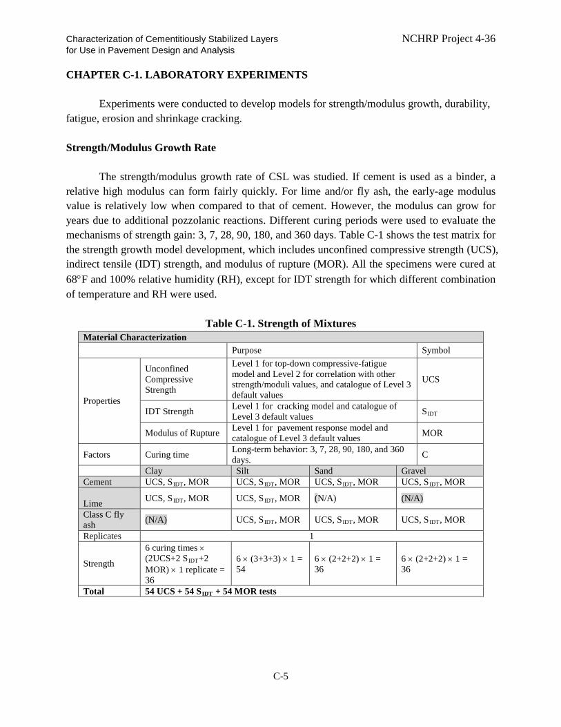
Characterization of Cementitiously Stabilized Layers NCHRP Project 4-36 for Use in Pavement Design and Analysis CHAPTER C-1. LABORATORY EXPERIMENTS
Experiments were conducted to develop models for strength/modulus growth, durability, fatigue, erosion and shrinkage cracking. Strength/Modulus Growth Rate
The strength/modulus growth rate of CSL was studied. If cement is used as a binder, a relative high modulus can form fairly quickly. For lime and/or fly ash, the early-age modulus value is relatively low when compared to that of cement. However, the modulus can grow for years due to additional pozzolanic reactions. Different curing periods were used to evaluate the mechanisms of strength gain: 3, 7, 28, 90, 180, and 360 days. Table C-1 shows the test matrix for the strength growth model development, which includes unconfined compressive strength (UCS), indirect tensile (IDT) strength, and modulus of rupture (MOR). All the specimens were cured at 68°F and 100% relative humidity (RH), except for IDT strength for which different combination of temperature and RH were used.
Table C-1. Strength of Mixtures Material Characterization Purpose Symbol
Properties
Unconfined Compressive Strength
Level 1 for top-down compressive-fatigue model and Level 2 for correlation with other strength/moduli values, and catalogue of Level 3 default values
UCS
IDT Strength Level 1 for cracking model and catalogue of Level 3 default values SIDT
Modulus of Rupture Level 1 for pavement response model and catalogue of Level 3 default values MOR
Factors Curing time Long-term behavior: 3, 7, 28, 90, 180, and 360 days. C
Clay Silt Sand Gravel Cement UCS, SIDT, MOR UCS, SIDT, MOR UCS, SIDT, MOR UCS, SIDT, MOR Lime UCS, SIDT, MOR UCS, SIDT, MOR (N/A) (N/A)
Class C fly ash (N/A) UCS, SIDT, MOR UCS, SIDT, MOR UCS, SIDT, MOR
Replicates 1
Strength
6 curing times × (2UCS+2 SIDT+2 MOR) × 1 replicate = 36
6 × (3+3+3) × 1 = 54
6 × (2+2+2) × 1 = 36
6 × (2+2+2) × 1 = 36
Total 54 UCS + 54 SIDT + 54 MOR tests
C-5

Characterization of Cementitiously Stabilized Layers NCHRP Project 4-36 for Use in Pavement Design and Analysis Unconfined Compressive Strength (UCS)
The UCS test is the most common test performed on cementitiously-stabilized materials
(CSM) for mix designs for use in pavement bases and subbases. The test methods for the different mixtures follow the recommendations in the Mechanistic-Empirical Pavement Design Guide (MEPDG) (ARA 2004). The specimens for all nine types of mixtures were compacted using standard Proctor compaction in a mold 4 inches in diameter and 4.6 inches in height. At the end of the moist-cure periods, all of the specimens except the lime-clay specimens were soaked in water for 4 hours prior to testing.
For the cement-stabilized fine-grained materials (clay, silt and sand), the ASTM D1633 test method was followed. The compression tests were conducted as soon as possible after removing the specimens from the water. The tests were conducted using a servo-hydraulic machine with the loading rate of 20 psi/sec. The AASHTO T22 test method was followed to test the cement-gravel specimens with the loading rate of 35 psi/sec. For the fly ash-stabilized soils, the ASTM C593 method was followed, and the loading rate was 35 psi/sec.
The lime-clay specimens were capillary-soaked for 24 hours prior to testing. The capillary soaking process is conducted by wrapping the specimens with wet absorptive fabric and placing them on a porous stone. The water level reaches the top of the stone and comes in contact with the fabric wrap throughout the capillary soaking process. However, the specimen is not in direct contact with the water, following the National Lime Association (NLA) procedure (NLA 2006). During the test, the load is applied with an axial deformation rate of approximately 2.0%/min, in accordance with the ASTM D5102 test method.
Figures C-1, C-2, and C-3 present the UCS, MOR, and IDT strength results for all nine mixtures, respectively.
Figure C-1. UCS Growth with Curing Age
0
500
1000
1500
2000
2500
UC
S (p
si)
UCS Growth
3 days
7 days
28 days
90 days
180 days
270 days
360 days
C-6

Characterization of Cementitiously Stabilized Layers NCHRP Project 4-36 for Use in Pavement Design and Analysis
Figure C-2. MOR Growth with Curing Age
Figure C-3. IDT Strength Growth with Curing Age
In order to establish the shrinkage cracking model, the IDT strength/modulus specimens
were prepared for 3, 7, 14, 28, and 56 days curing at various RH and temperatures, because early-stage shrinkage cracking and the IDT strength/moduli are sensitive to environmental conditions. Five mixtures were tested with three replicates, including cement-clay, cement-silt, cement-gravel, lime-clay, and C fly ash-silt, as shown in Table C-2. Figures C-4 and C-5 present the IDT strength and IDT modulus growth test results, respectively.
020406080
100120140160180
MO
R (p
si)
MOR Growth
3 days
7 days
28 days
90 days
180 days
360 days
0
50
100
150
200
250
IDT
Str
engt
h (p
si)
IDT Strength Growth
3 days
7 days
28 days
90 days
180 days
270 days
360 days
C-7

Characterization of Cementitiously Stabilized Layers NCHRP Project 4-36 for Use in Pavement Design and Analysis
Table C-2. IDT Strength and Modulus of Mixtures Material Characterization
Purpose Symbol
Properties IDT Strength Level 1 for cracking response model and
catalogue of Level 3 default values SIDT
IDT Modulus Level 1 for cracking response model and catalogue of Level 3 default values ET
Factors Curing time Long-term behavior: 3, 7, 14, 28, and 56 days at various temperatures and RH C
Clay Silt Sand Gravel Cement SIDT, Et SIDT, Et - SIDT, Et
Lime SIDT, Et - (N/A) (N/A) Class C fly
ash (N/A) SIDT, Et - -
Replicates 3
Total 12 materials/environment × 5 curing time × 3 replicates =180 IDT Strength and 180 IDT Modulus Tests
(a) Cement-Clay, 68°F & 65%RH (b) Cement-Clay, 68°F & 40%RH
(c) Cement-Clay, 104°F & 40%RH (d) Cement-Silt, 68°F & 65%RH
020406080
100120
3 7 14 28 56
IDT
Str
engt
h (p
si)
Curing Age (Days)
IDT Strength (Cement-Clay, 68°F & 65%RH)
Specimen 1
Specimen 2
Specimen 3
Average 0.020.040.060.080.0
100.0120.0
3 7 14 28 56
IDT
Str
engt
h (p
si)
Curing Age (Days)
IDT Strength (Cement-Clay, 68°F & 40%RH)
Specimen 1
Specimen 2
Specimen 3
Average
0.0
50.0
100.0
150.0
200.0
3 7 14 28 56
IDT
Str
engt
h (p
si)
Curing Age (Days)
IDT Strength (Cement-Clay, 104°F & 40%RH)
Specimen 1
Specimen 2
Specimen 3
Average 0
50
100
150
200
3 7 14 28 56
IDT
Str
engt
h (p
si)
Curing Age (Days)
IDT Strength (Cement-Silt, 68°F & 65%RH)
Specimen 1
Specimen 2
Specimen 3
Average
C-8

Characterization of Cementitiously Stabilized Layers NCHRP Project 4-36 for Use in Pavement Design and Analysis
(e) Cement-Silt, 68°F & 40%RH (f) Cement-Silt, 104°F & 40%RH
(g) Cement-Silt, 68°F & 90%RH (h) Cement-Gravel, 68°F & 65%RH
(i) Lime-Clay, 68°F & 65%RH (j) Lime-Clay, 68°F & 40%RH
0.0
50.0
100.0
150.0
200.0
3 7 14 28 56
IDT
Str
engt
h (p
si)
Curing Age (Days)
IDT Strength (Cement-Silt, 68°F & 40%RH)
Specimen 1
Specimen 2
Specimen 3
Average 0.0
50.0
100.0
150.0
200.0
250.0
3 7 14 28 56
IDT
Str
engt
h (p
si)
Curing Age (Days)
IDT Strength (Cement-Silt, 104°F & 40%RH)
Specimen 1
Specimen 2
Specimen 3
Average
0
50
100
150
3 7 14 28 56
IDT
Str
engt
h (p
si)
Curing Age (Days)
IDT Strength (Cement-Silt, 68°F & 90%RH)
Specimen 1
Specimen 2
Specimen 3
Average 0.0
50.0
100.0
150.0
3 7 14 28 56
IDT
Str
engt
h (p
si)
Curing Age (Days)
IDT Strength (Cement-Gravel, 68°F & 65%RH)
Specimen 1
Specimen 2
Specimen 3
Average
0.0
5.0
10.0
15.0
20.0
3 7 14 28 56
IDT
Str
engt
h (p
si)
Curing Age (Days)
IDT Strength (Lime-Clay, 68°F & 65%RH)
Specimen 1
Specimen 2
Specimen 3
Average 0.0
5.0
10.0
15.0
20.0
3 7 14 28 56
IDT
Str
engt
h (p
si)
Curing Age (Days)
IDT Strength (Lime-Clay, 68°F & 40%RH)
Specimen 1
Specimen 2
Specimen 3
Average
C-9

Characterization of Cementitiously Stabilized Layers NCHRP Project 4-36 for Use in Pavement Design and Analysis
(k) Lime-Clay, 104°F & 40%RH (l) C Fly Ash-Silt, 68°F & 65%RH
Figure C-4. IDT Strength Values at Various RH and Temperatures with Curing Age
(a) Cement-Clay, 68°F & 65% RH (b) Cement-Clay, 68°F & 40% RH
(c) Cement-Clay, 104°F & 40% RH (d) Cement-Silt, 68°F & 65% RH
0.0
20.0
40.0
60.0
80.0
3 7 14 28 56
IDT
Str
engt
h (p
si)
Curing Age (Days)
IDT Strength (Lime-Clay, 104°F & 40%RH)
Specimen 1
Specimen 2
Specimen 3
Average 0.0
5.0
10.0
15.0
20.0
25.0
3 7 14 28 56
IDT
Str
engt
h (p
si)
Curing Age (Days)
IDT Strength (C Fly Ash-Silt, 68°F & 65%RH)
Specimen 1
Specimen 2
Specimen 3
Average
0
200000
400000
600000
800000
3 7 14 28 56
IDT
Mod
ulus
(psi
)
Curing Age (Days)
IDT Modulus-30% Load Level (Cement-Clay, 68°F & 65% RH)
Specimen 1
Specimen 2
Specimen 3
Average 0
200000
400000
600000
800000
1000000
3 7 14 28 56
IDT
Mod
ulus
(psi
)
Curing Age (Days)
IDT Modulus-30% Load Level (Cement-Clay, 68°F & 40% RH)
Specimen 1
Specimen 2
Specimen 3
Average
0
200000
400000
600000
800000
1000000
1 2 3 4 5
IDT
Mod
ulus
(psi
)
Curing Age (Days)
IDT Modulus-30% Load Level (Cement-Clay, 104°F & 40% RH)
Specimen 1
Specimen 2
Specimen 3
Average 0
500000
1000000
1500000
2000000
3 7 14 28 56
IDT
Mod
ulus
(psi
)
Curing Age (Days)
IDT Modulus-30% Load Level (Cement-Silt, 68°F & 65% RH)
Specimen 1
Specimen 2
Specimen 3
Average
C-10

Characterization of Cementitiously Stabilized Layers NCHRP Project 4-36 for Use in Pavement Design and Analysis
(e) Cement-Silt, 68°F & 40% RH (f) Cement-Silt, 104°FS & 40% RH
(g) Cement-Silt, 68°F & 90% RH (h) Cement-Gravel, 68°F & 65% RH
(i) Lime-Clay, 68°F & 65% RH (j) Lime-Clay, 68°F & 40% RH
0
500000
1000000
1500000
2000000
3 7 14 28 56
IDT
Mod
ulus
(psi
)
Curing Age (Days)
IDT Modulus-30% Load Level (Cement-Silt, 68°F & 40% RH)
Specimen 1
Specimen 2
Specimen 3
Average 0
500000
1000000
1500000
3 7 14 28 56
IDT
Mod
ulus
(psi
)
Curing Age (Days)
IDT Modulus-30% Load Level (Cement-Silt, 104°F & 40% RH)
Specimen 1
Specimen 2
Specimen 3
Average
0
500000
1000000
1500000
3 7 14 28 56
IDT
Mod
ulus
(psi
)
Curing Age (Days)
IDT Modulus-30% Load Level (Cement-Silt, 68°F & 90% RH)
Specimen 1
Specimen 2
Specimen 3
Average 0
500000
1000000
1500000
2000000
2500000
3 7 14 28 56
IDT
Mod
ulus
(psi
)
Curing Age (Days)
IDT Modulus-30% Load Level (Cement-Gravel, 68°F & 65% RH)
Specimen 1
Specimen 2
Specimen 3
Average
0
50000
100000
150000
3 7 14 28 56
IDT
Mod
ulus
(psi
)
Curing Age (Days)
IDT Modulus-30% Load Level (Lime-Clay, 68°F & 65% RH)
Specimen 1
Specimen 2
Specimen 3
Average 0
50000
100000
150000
200000
3 7 14 28 56
IDT
Mod
ulus
(psi
)
Curing Age (Days)
IDT Modulus-30% Load Level (Lime-Clay, 68°F & 40% RH)
Specimen 1
Specimen 2
Specimen 3
Average
C-11
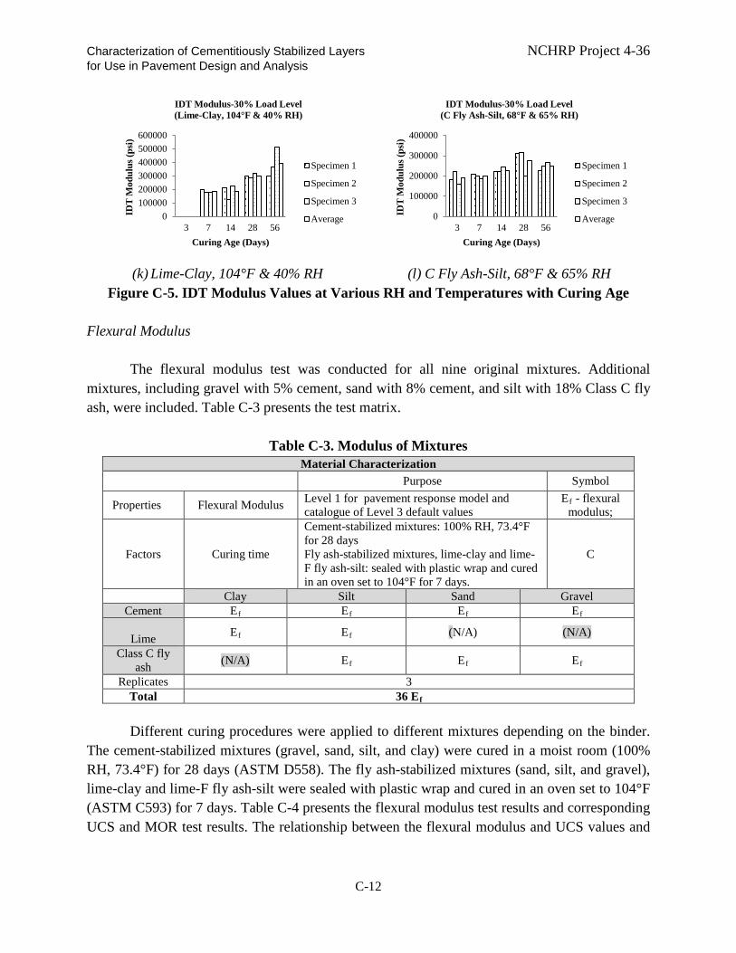
Characterization of Cementitiously Stabilized Layers NCHRP Project 4-36 for Use in Pavement Design and Analysis
(k) Lime-Clay, 104°F & 40% RH (l) C Fly Ash-Silt, 68°F & 65% RH
Figure C-5. IDT Modulus Values at Various RH and Temperatures with Curing Age Flexural Modulus
The flexural modulus test was conducted for all nine original mixtures. Additional
mixtures, including gravel with 5% cement, sand with 8% cement, and silt with 18% Class C fly ash, were included. Table C-3 presents the test matrix.
Table C-3. Modulus of Mixtures
Material Characterization Purpose Symbol
Properties Flexural Modulus Level 1 for pavement response model and catalogue of Level 3 default values
Ef - flexural modulus;
Factors Curing time
Cement-stabilized mixtures: 100% RH, 73.4°F for 28 days Fly ash-stabilized mixtures, lime-clay and lime-F fly ash-silt: sealed with plastic wrap and cured in an oven set to 104°F for 7 days.
C
Clay Silt Sand Gravel Cement Ef Ef Ef Ef
Lime Ef Ef (N/A) (N/A)
Class C fly ash (N/A) Ef Ef Ef
Replicates 3 Total 36 Ef
Different curing procedures were applied to different mixtures depending on the binder.
The cement-stabilized mixtures (gravel, sand, silt, and clay) were cured in a moist room (100% RH, 73.4°F) for 28 days (ASTM D558). The fly ash-stabilized mixtures (sand, silt, and gravel), lime-clay and lime-F fly ash-silt were sealed with plastic wrap and cured in an oven set to 104°F (ASTM C593) for 7 days. Table C-4 presents the flexural modulus test results and corresponding UCS and MOR test results. The relationship between the flexural modulus and UCS values and
0100000200000300000400000500000600000
3 7 14 28 56
IDT
Mod
ulus
(psi
)
Curing Age (Days)
IDT Modulus-30% Load Level (Lime-Clay, 104°F & 40% RH)
Specimen 1
Specimen 2
Specimen 3
Average 0
100000
200000
300000
400000
3 7 14 28 56
IDT
Mod
ulus
(psi
)
Curing Age (Days)
IDT Modulus-30% Load Level (C Fly Ash-Silt, 68°F & 65% RH)
Specimen 1
Specimen 2
Specimen 3
Average
C-12

Characterization of Cementitiously Stabilized Layers NCHRP Project 4-36 for Use in Pavement Design and Analysis between the flexural modulus and the MOR values can be developed. The growth of the UCS and MOR was used to establish the growth of the flexural modulus, as shown in the main report.
Table C-4. Flexural Modulus Results with Corresponding UCS and MOR Results Materials UCS (psi) MOR (psi) Flexural Modulus (psi)
Clay–cement (12%) 534 94 144,893 Gravel–cement (3%) 640 79 134,740 Sand–cement (6%) 521 71 141,122 Silt–cement (8%) 653 81 131,114 Clay–lime (6%) 149 27 87,168
Gravel–class C fly ash (13%) 289 49 119,076 Sand–class C fly ash (13%) 206 51 104,427 Silt–class C fly ash (13%) 91 18 65,847
Silt–lime–class F fly ash (4%-12%) 271 48 124,297 Gravel–cement (5%) 145 193,625 Sand–cement (8%) 145 200,007
Silt–class C fly ash (18%) 28 85,137
Durability
Durability tests, including wet-dry and freeze-thaw tests, were conducted to develop the durability models. Cement-silt, C fly ash-gravel, lime-clay, and C fly ash-silt materials were selected to represent materials with strength values from high to low for wet-dry testing. Table C-5 presents the test matrix.
Table C-5. Laboratory Test Plan for Durability Model
Durability Model Purpose Symbol
Durability Tests Freeze-thaw Develop freeze-thaw
durability model F-T
Wet-dry Develop wet-dry durability model W-D
Clay Silt Sand Gravel
Cement F-T F-T, W-D F-T F-T
Lime F-T, W-D F-T (N/A) (N/A)
Class C fly ash (N/A) F-T, W-D F-T F-T, W-D Total 39 F-T + 30 W-D Tests
C-13

Characterization of Cementitiously Stabilized Layers NCHRP Project 4-36 for Use in Pavement Design and Analysis Wet-Dry
Figure C-6 presents the UCS results of the wet-dry tests. It is noted that the control group
is subjected to the same temperature as the wet-dry group, except that the control group is not submerged in water, as per the procedures outlined in Appendix B. This is to single out the effect of moisture only and to eliminate the effects of high temperature on the material properties.
(a) Cement-Silt (6 Cycles) (b) Lime-Clay (9 Cycles)
(c) C Fly Ash-Gravel (13 Cycles) (d) C Fly Ash-Silt (1 Cycles)
(e) C Fly Ash-Silt (3 Cycles) (f) C Fly Ash-Silt (5 Cycles)
Figure C-6. UCS Test Results of Wet-Dry and Control Specimens
0
500
1000
1500
2000
2500
Wet-Dry Control
UC
S (p
si)
UCS of WD-Control (Cement-Silt, 6 Cycles)
Specimen 1
Specimen 2
Specimen 3
Average
0
100
200
300
400
500
Wet-Dry Control
UC
S (p
si)
UCS of WD-Control (Lime-Clay, 9 Cycles)
Specimen 1
Specimen 2
Specimen 3
Average
0200400600800
100012001400
Wet-Dry Control
UC
S (p
si)
UCS of WD-Control (C Fly Ash-Gravel, 13 Cycles)
Specimen 1
Specimen 2
Specimen 3
Average
0
20
40
60
80
100
Wet-Dry Control
UC
S (p
si)
UCS of WD-Control (C Fly Ash-Silt, 1 Cycles)
Specimen 1
Specimen 2
Specimen 3
Average
0
20
40
60
80
100
Wet-Dry Control
UC
S (p
si)
UCS of WD-Control (C Fly Ash-Silt, 3 Cycles)
Specimen 1
Specimen 2
Specimen 3
Average
0
50
100
150
200
Wet-Dry Control
UC
S (p
si)
UCS of WD-Control (C Fly Ash-Silt, 5 Cycles)
Specimen 1
Specimen 2
Specimen 3
Average
C-14

Characterization of Cementitiously Stabilized Layers NCHRP Project 4-36 for Use in Pavement Design and Analysis Freeze-Thaw
Freeze-thaw tests were conducted to develop freeze-thaw durability models. The cement-stabilized mixtures (gravel, sand, silt, and clay) were cured in a moist room at 100% RH and 70°F for 28 days in accordance with ASTM D558. Based on the test procedure evaluation results presented in Appendix B, the fly ash-stabilized mixtures (sand, silt, and gravel), clay-lime, and silt-lime-Class F fly ash were sealed with plastic wrap and cured for 7 days in an oven set to 104°F in accordance with ASTM C593. The number of freeze-thaw cycles was varied amongst the different mixtures to incorporate the effect of the number of cycles in the model. The UCS of the specimens was measured after the designated freeze-thaw cycles. Figure C-7 presents the UCS results before and after the freeze-thaw tests.
(a) Cement-Gravel (2 Cycles) (b) Cement-Sand (12 Cycles)
(c) Cement-Silt (6 Cycles) (d) Cement-Silt (7 Cycles)
0
100
200
300
400
500
600
700
Freeze-Thaw Control
UC
S (p
si)
UCS of FT-Control (Cement-Gravel, 2 Cycles)
Specimen 1Specimen 2Specimen 3AverageSpecimen 1
0100200300400500600700800
Freeze-Thaw Control
UC
S (p
si)
UCS of FT-Control (Cement-Sand, 12 Cycles)
Specimen 1
Specimen 2
Specimen 3
Average
Specimen 1
0100200300400500600700
Freeze-Thaw Control
UC
S (p
si)
(a) Cement-Silt (6 Cycles)
UCS of FT-Control (Cement-Silt, 6 Cycles)
Specimen 1
Specimen 2
Average
Specimen 1
0100200300400500600700
Freeze-Thaw Control
UC
S (p
si)
(a) Cement-Silt (7 Cycles)
UCS of FT-Control (Cement-Silt, 7 Cycles)
Specimen 1
Specimen 2
Average
Specimen 1
C-15

Characterization of Cementitiously Stabilized Layers NCHRP Project 4-36 for Use in Pavement Design and Analysis
(e) Cement-Clay (12 Cycles) (f) C Fly Ash-Gravel (4 Cycles)
(g) C Fly Ash-Silt (1 Cycles) (h) C Fly Ash-Sand (12 Cycles)
(i) Lime C Fly Ash-Silt (3 Cycles) (j) Lime C Fly Ash-Silt (6 Cycles)
0
100
200
300
400
500
600
Freeze-Thaw Control
UC
S (p
si)
UCS of FT-Control (Cement-Clay, 12 Cycles)
Specimen 1
Specimen 2
Specimen 3
Average
Specimen 1
050
100150200250300350
Freeze-Thaw Control
UC
S (p
si)
UCS of FT-Control (C Flay Ash-Gravel, 4 Cycles)
Specimen 1
Specimen 2
Specimen 3
Average
Specimen 1
0
20
40
60
80
100
Freeze-Thaw Control
UC
S (p
si)
UCS of FT-Control (C Flay Ash-Silt, 1 Cycles)
Specimen 1
Specimen 2
Specimen 3
Average
Specimen 1
0
100
200
300
400
500
Freeze-Thaw Control
UC
S (p
si)
UCS of FT-Control (C Flay Ash-Sand, 12 Cycles)
Specimen 1
Specimen 2
Specimen 3
Average
Specimen 1
0
50
100
150
200
250
300
Freeze-Thaw Control
UC
S (p
si)
UCS of FT-Control (Lime F Flay Ash-Silt, 3 Cycles)
Specimen 1
Specimen 1
0
50
100
150
200
250
300
Freeze-Thaw Control
UC
S (p
si)
UCS of FT-Control (Lime F Flay Ash-Silt, 6 Cycles)
Specimen 1
Specimen 2
Average
Specimen 1
C-16

Characterization of Cementitiously Stabilized Layers NCHRP Project 4-36 for Use in Pavement Design and Analysis
(k) Lime-Clay (2 Cycles)
Figure C-7. UCS Test Results of Freeze-Thaw and Control Specimens
Fatigue Test Bottom-Up Tensile-Fatigue Test
The bottom-up tensile-fatigue test was initiated immediately after the flexural modulus
test on the same specimen. The same setup as that used in the flexural modulus test was followed for the bottom-up tensile-fatigue test. The peak magnitude of the haversine load pulses ranges from 45% to 95% of the breaking load (based on the beams that were tested for strength). The bottom-up tensile-fatigue test was conducted with a haversine pulse width of 250-ms duration with 250-ms rest between pulses for a total 500-ms pulse periods (2 Hz frequency) to expedite the tests, which is different from the test procedure evaluation presented in Appendix B. Table C-6 presents the laboratory test plan.
Top-Down Compressive-Fatigue-Erosion Test
The top-down compressive-fatigue-erosion test was developed based on the cyclic impact
erosion (CIE) test. Table C-7 presents the test plan. Different displacement levels and frequencies were used. Table C-8 presents the measured fatigue life data. Fatigue life is defined as the number of cycles that can reduce the initial modulus value by 50 percent.
020406080
100120140160
Freeze-Thaw ControlU
CS
(psi
)
UCS of FT-Control (Lime-Clay, 2 Cycles)
Specimen 1
Specimen 2
Specimen 3
Average
Specimen 1
C-17

Characterization of Cementitiously Stabilized Layers NCHRP Project 4-36 for Use in Pavement Design and Analysis
Table C-6. Laboratory Test Plan for Bottom-Up Tensile-Fatigue Test Fatigue Model
Purpose Symbol
Material Properties
Modulus of Rupture Level 1 material properties in the fatigue model and catalog of Level 3 default values MOR
Unconfined Compressive
Strength Correlation with other strength values UCS
Fatigue Tests Beam Fatigue Fatigue model development Beam Clay Silt Sand Gravel
Cement MOR, UCS, Beam MOR, UCS, Beam MOR, UCS, Beam MOR, UCS, Beam
Lime MOR, UCS, Beam MOR, UCS, Beam (N/A) (N/A)
Class C fly ash (N/A) MOR, UCS, Beam MOR, UCS, Beam MOR, UCS, Beam Replicate 1
Subtotal 2 MOR +2 UCS + 2 beam 3+3+3 2+2+2 2+2+2
Total 12 MOR + 12 UCS + 12 beam fatigue tests
Table C-7 Laboratory Test Plan for Top-Down Compressive-Fatigue-Erosion Test Erosion Model
Purpose Symbol
Material Property
Unconfined Compressive
Strength
Material property in erosion model UCS
Model Development
Cyclic Impact Erosion Model validation CIE
Clay Silt Sand Gravel Cement - - - UCS, CIE
Lime UCS, CIE - (N/A) (N/A)
Class C fly ash (N/A) UCS, CIE UCS, CIE UCS, CIE Total 5 UCS + 21 CIE
C-18

Characterization of Cementitiously Stabilized Layers NCHRP Project 4-36 for Use in Pavement Design and Analysis
Table C-8 Laboratory CIE Test Results
Materials Frequency (Hz) Initial
Displacement (in.)
Measured Fatigue Life
Cement-Silt 1 0.031 388 Lime-Clay 4 0.031 31
C Fly Ash-Silt 10 0.016 90 C Fly Ash-Sand 10 0.015 11,416
C Fly Ash-Gravel 1 0.031 3,435
Cement-Gravel
1 0.028 31,416 1 0.034 3,098 1 0.041 313 1 0.048 424
C Fly Ash-Silt
2 0.015 710 2 0.017 1,344 1 0.028 870 2 0.023 41 2 0.026 16 2 0.031 30
Lime-Clay
1 0.015 97 1 0.021 331 1 0.029 80 1 0.036 70 1 0.044 46 1 0.051 35
Shrinkage and Cracking Test
The shrinkage cracking models consist of models for ultimate shrinkage strain, gradient drying shrinkage strain, crack spacing and width. Table C-9 presents the laboratory test plan for the shrinkage model.
C-19
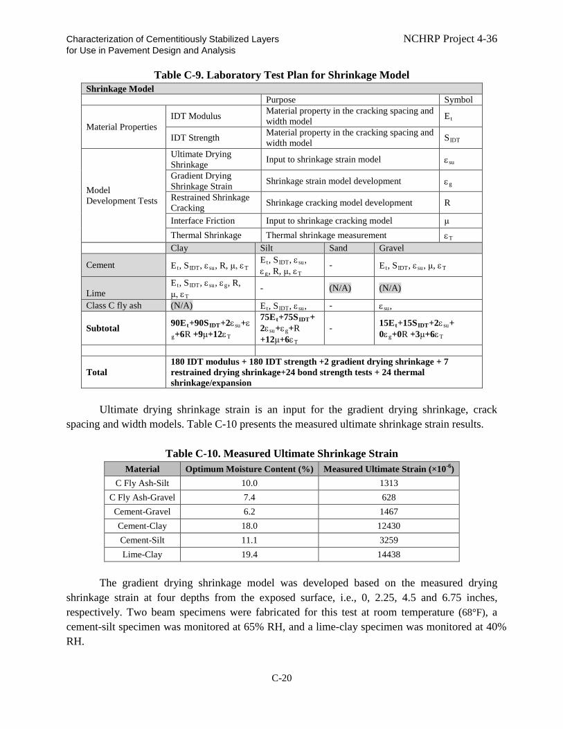
Characterization of Cementitiously Stabilized Layers NCHRP Project 4-36 for Use in Pavement Design and Analysis
Table C-9. Laboratory Test Plan for Shrinkage Model Shrinkage Model Purpose Symbol
Material Properties IDT Modulus Material property in the cracking spacing and
width model Et
IDT Strength Material property in the cracking spacing and width model SIDT
Model Development Tests
Ultimate Drying Shrinkage Input to shrinkage strain model εsu
Gradient Drying Shrinkage Strain Shrinkage strain model development εg
Restrained Shrinkage Cracking Shrinkage cracking model development R
Interface Friction Input to shrinkage cracking model μ Thermal Shrinkage Thermal shrinkage measurement εT
Clay Silt Sand Gravel
Cement Et, SIDT, εsu, R, μ, εT Et, SIDT, εsu, εg, R, μ, εT
- Et, SIDT, εsu, μ, εT
Lime
Et, SIDT, εsu, εg, R, μ, εT
- (N/A) (N/A)
Class C fly ash (N/A) Et, SIDT, εsu, - εsu,
Subtotal 90Et+90SIDT+2εsu+εg+6R +9μ+12εT
75Et+75SIDT+2εsu+εg+R +12μ+6εT
- 15Et+15SIDT+2εsu+ 0εg+0R +3μ+6εT
Total 180 IDT modulus + 180 IDT strength +2 gradient drying shrinkage + 7 restrained drying shrinkage+24 bond strength tests + 24 thermal shrinkage/expansion
Ultimate drying shrinkage strain is an input for the gradient drying shrinkage, crack
spacing and width models. Table C-10 presents the measured ultimate shrinkage strain results.
Table C-10. Measured Ultimate Shrinkage Strain Material Optimum Moisture Content (%) Measured Ultimate Strain (×10-6)
C Fly Ash-Silt 10.0 1313 C Fly Ash-Gravel 7.4 628 Cement-Gravel 6.2 1467 Cement-Clay 18.0 12430 Cement-Silt 11.1 3259 Lime-Clay 19.4 14438
The gradient drying shrinkage model was developed based on the measured drying
shrinkage strain at four depths from the exposed surface, i.e., 0, 2.25, 4.5 and 6.75 inches, respectively. Two beam specimens were fabricated for this test at room temperature (68°F), a cement-silt specimen was monitored at 65% RH, and a lime-clay specimen was monitored at 40% RH.
C-20
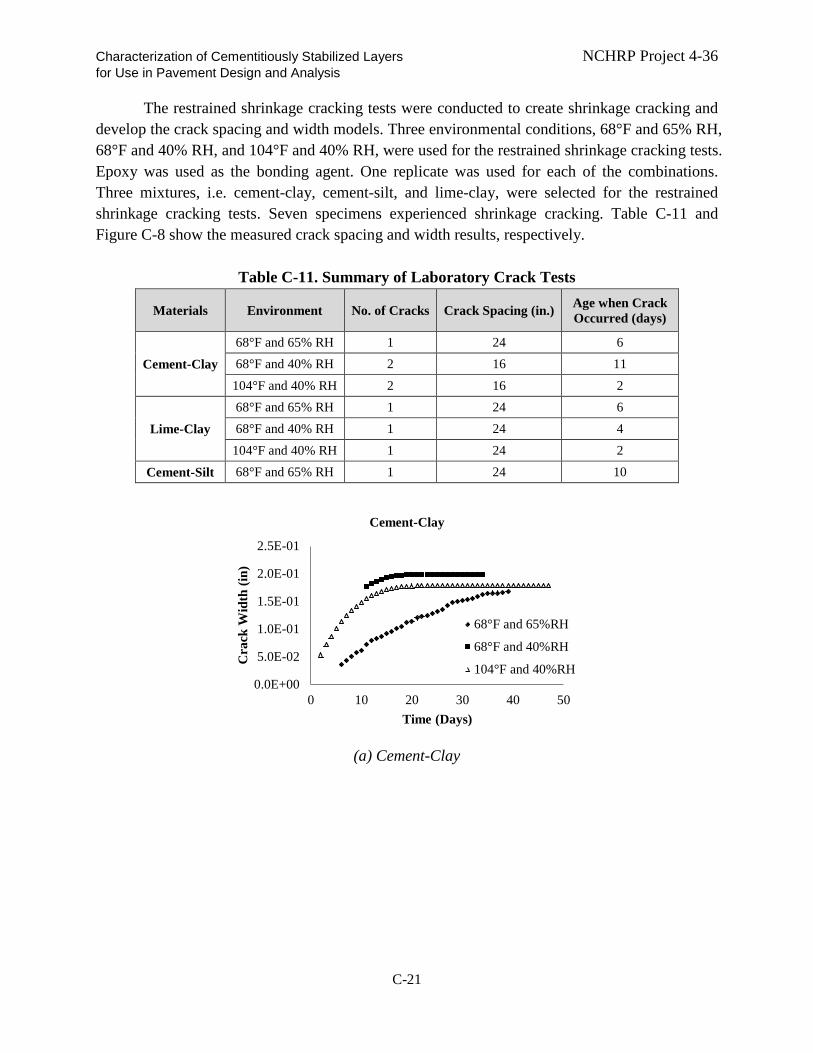
Characterization of Cementitiously Stabilized Layers NCHRP Project 4-36 for Use in Pavement Design and Analysis
The restrained shrinkage cracking tests were conducted to create shrinkage cracking and develop the crack spacing and width models. Three environmental conditions, 68°F and 65% RH, 68°F and 40% RH, and 104°F and 40% RH, were used for the restrained shrinkage cracking tests. Epoxy was used as the bonding agent. One replicate was used for each of the combinations. Three mixtures, i.e. cement-clay, cement-silt, and lime-clay, were selected for the restrained shrinkage cracking tests. Seven specimens experienced shrinkage cracking. Table C-11 and Figure C-8 show the measured crack spacing and width results, respectively.
Table C-11. Summary of Laboratory Crack Tests
Materials Environment No. of Cracks Crack Spacing (in.) Age when Crack Occurred (days)
Cement-Clay 68°F and 65% RH 1 24 6 68°F and 40% RH 2 16 11
104°F and 40% RH 2 16 2
Lime-Clay 68°F and 65% RH 1 24 6 68°F and 40% RH 1 24 4
104°F and 40% RH 1 24 2
Cement-Silt 68°F and 65% RH 1 24 10
(a) Cement-Clay
0.0E+00
5.0E-02
1.0E-01
1.5E-01
2.0E-01
2.5E-01
0 10 20 30 40 50
Cra
ck W
idth
(in)
Time (Days)
Cement-Clay
68°F and 65%RH
68°F and 40%RH
104°F and 40%RH
C-21

Characterization of Cementitiously Stabilized Layers NCHRP Project 4-36 for Use in Pavement Design and Analysis
(b) Lime-Clay
(c) Cement-Silt
Figure C-8. Measured Crack Width
0.0E+00
5.0E-02
1.0E-01
1.5E-01
2.0E-01
2.5E-01
0 10 20 30 40 50
Cra
ck W
idth
(in)
Time (Days)
Lime-Clay
68°F and 65%RH
68°F and 40%RH
104°F and 40%RH
0.0E+00
2.0E-02
4.0E-02
6.0E-02
8.0E-02
0 20 40 60 80 100
Cra
ck W
idth
(m)
Time (Days)
Cement-Silt
68°F and 65%RH
C-22

Characterization of Cementitiously Stabilized Layers NCHRP Project 4-36 for Use in Pavement Design and Analysis CHAPTER C-2. DEVELOPMENT OF PERFORMANCE MODELS The performance models, including fatigue, durability, erosion, and shrinkage cracking models, were developed based on the laboratory experiments. Fatigue Models
Fatigue is one of the major distresses of cementitiously-stabilized layers (CSL) in a
pavement. A fatigue model of CSL is needed to predict the fatigue performance of CSL in the field. Two types of fatigue have been identified: bottom tension and top compression. Bottom tension fatigue is due to the repeated tensile stress/strain at the bottom of the CSL due to repeated traffic loads. Top compression fatigue stems from repeated compressive stress at the top of the CSL.
Bottom-up Fatigue Models
The fatigue life (N) of CSL due to tension at the bottom of the layer usually is considered
to be a function of the applied tensile stress (σt), the applied tensile strain (εt), or a ratio of these responses to the breaking stress (σb) or breaking strain (εb) of the material. The general form of the relationship typically is shown as Eq. (C-1).
log𝑁𝑁 = 𝑓𝑓𝑛𝑛 �𝜎𝜎𝑡𝑡𝜎𝜎𝑏𝑏
𝑜𝑜𝑜𝑜 𝜀𝜀𝑡𝑡𝜀𝜀𝑏𝑏� Eq. (C-1)
Various forms of the fatigue models are summarized by Yeo (2008), as follows.
1. Strain-based models
(a) South Africa Department of Transport model (Freeme et al. 1982)
𝐿𝐿𝑜𝑜𝐿𝐿 𝑁𝑁 = 9.1 �1 − 𝑑𝑑𝑠𝑠𝜀𝜀𝑡𝑡𝜀𝜀𝑏𝑏� Eq. (C-2)
where
ds = factor to account for shrinkage crack-induced stress concentration, as shown in Table C-12.
The above South African model was revised in 1995 with a shift factor (SF) to account
for crack propagation induced by load repetition (Theyse et al. 1995), as follows.
SF =10(0.00285d-0.293) if 102 < d < 419;
C-23

Characterization of Cementitiously Stabilized Layers NCHRP Project 4-36 for Use in Pavement Design and Analysis
SF = 1 if d < 102; SF = 8 if d > 419,
where
d = the thickness in mm, 1 inch = 25.4 mm
Table C-12. Correction Factors for Tensile Stress (Otte 1978)
Type of cracking
Unconfined compressive strength (psi)
Factor, d for total thickness of cemented material (in.)
<8 >8
Weakly cemented:
Moderate cracking; crack widths less than 0.08 in. (e.g., natural materials with lime or 2% to 3% cement)
109 - 218 1.1 1.2
218 - 435 1.15 1.3
Strongly cemented
Extensive cracking; crack widths more than 0.08 in. (e.g., high-quality natural gravel and crushed stone with 4% to 6% cement)
435 - 1740 1.25 1.4
(b) Australian models
The relationship between the maximum tensile strain in cemented materials produced by
a specific load and the allowable number of repetitions of that load is given by the following expression (National Association of Australian State Road Authorities (NAASRA) 1987).
𝐿𝐿𝑜𝑜𝐿𝐿 𝑁𝑁 = 18 𝐿𝐿𝑜𝑜𝐿𝐿 �𝐶𝐶𝜀𝜀𝑡𝑡� Eq. (C-3)
where
C = 280; E = 290 psi C = 200; E = 725 psi C = 150; E ≥ 1450 psi E = modulus of the cemented material.
Litnowicz and Brandon (1994) note a disadvantage with the above fatigue relationship
for cemented materials, as the implied values of the strain at the breaking point (εb) for the various cemented material moduli tend to exceed the upper bound of the laboratory εb values
C-24

Characterization of Cementitiously Stabilized Layers NCHRP Project 4-36 for Use in Pavement Design and Analysis reported in the literature. As such, the current Austroads fatigue relationship for cemented materials is reworked as:
𝐿𝐿𝑜𝑜𝐿𝐿 𝑁𝑁 = 𝑅𝑅𝑅𝑅 ∙ 12 �11300𝐸𝐸0.804+191
𝜖𝜖𝑡𝑡� Eq. (C-4)
where
RF = reliability factor (RF = 2 for 90% reliability, RF = 1 for 95% reliability and RF = 0.5 for 97.5% reliability), and the other terms are as described previously.
2. Stress-based Models
(a) French model The French design for CSL is based on direct tensile strength, as follows (Corte and
Goux 1996). 𝐿𝐿𝑜𝑜𝐿𝐿 𝑁𝑁 = 1
𝐵𝐵(𝜎𝜎𝑡𝑡𝜎𝜎𝑏𝑏− 1) Eq. (C-5)
where B = regression constant.
(b) MEPDG fatigue model The MEPDG proposes the following fatigue distress model (ARA 2004).
log𝑁𝑁 = �𝑘𝑘1𝛽𝛽𝑐𝑐1−�
𝜎𝜎𝑠𝑠𝑀𝑀𝑀𝑀𝑀𝑀�
𝑘𝑘2𝛽𝛽𝑐𝑐2� Eq. (C-6)
where N = number of repetitions to fatigue cracking σs = tensile stress at the bottom of CSL, psi MOR = modulus of rupture, psi k1, k2, βc1, and βc2 = regression/calibration coefficients.
The accumulated damage is based on Miner’s law in the MEPDG, as shown in Eq. (C-7)
(ARA 2004). 𝐷𝐷 = ∑ 𝑛𝑛i
𝑁𝑁i𝑗𝑗𝑖𝑖=1 Eq. (C-7)
where
C-25

Characterization of Cementitiously Stabilized Layers NCHRP Project 4-36 for Use in Pavement Design and Analysis
ni = actual number of repetitions of load group i Ni = allowed number of repetitions to fatigue of load group i j = total number of load groups.
According to the MEPDG, after fatigue damage is induced, the modulus of the CSL is
reduced, which affects the pavement response. The modulus of the deteriorated CSL in the MEPDG is expressed as (ARA 2004):
𝐸𝐸𝐶𝐶𝐶𝐶𝐶𝐶(𝑡𝑡) = 𝐸𝐸𝐶𝐶𝐶𝐶𝐶𝐶(𝑚𝑚𝑚𝑚𝑚𝑚) + 𝐸𝐸𝐶𝐶𝐶𝐶𝑀𝑀(𝑚𝑚𝑚𝑚𝑚𝑚)−𝐸𝐸𝐶𝐶𝐶𝐶𝑀𝑀(𝑚𝑚𝑖𝑖𝑛𝑛)1+𝑒𝑒(−4+14𝐷𝐷) Eq. (C-8)
where
ECSM(t) = new CSL modulus at a damage level of D, psi. ECSM(max) = maximum CSL modulus for intact layer, psi. ECSM(min) = minimum CSL modulus after total layer destruction, psi. D = CSL damage level, in decimal form.
For the minimum modulus values for CSL after damage, Table C-13 is used in the
MEPDG (ARA 2004).
Table C-13. Deteriorated Modulus of CSL Chemically Stabilized Material Deteriorated Mf Typical, psi
Lean concrete 300,000 Cement-stabilized aggregate 100,000
Open-graded cement-stabilized 50,000 Soil-cement 25,000
Lime-cement-fly ash 40,000 Lime-stabilized soils 15,000
After the damaged modulus of the CSL is determined, the damaged modulus is then used
in the MEPDG for pavement analysis within each time interval of the analysis. The fatigue cracking of the CSL in the MEPDG is determined based on Eq. (C-9) (ARA
2004). 𝐶𝐶 = 1000
1+𝑒𝑒(1−𝐷𝐷) Eq. (C-9)
where C = CSL cracking in units of feet per 500-ft long sections. D = accumulated fatigue damage.
C-26

Characterization of Cementitiously Stabilized Layers NCHRP Project 4-36 for Use in Pavement Design and Analysis Top-down Compressive-Fatigue Model
The South Africa study proposes a top-down compressive-fatigue model as shown by Eq.
(C-10) (De Beer 1990).
𝑙𝑙𝑜𝑜𝐿𝐿𝑁𝑁 = 𝑘𝑘1 �1 − 𝜎𝜎𝑐𝑐𝑘𝑘2 𝑈𝑈𝐶𝐶𝐶𝐶
� Eq. (C-10)
where
N = number of repetitions to fatigue cracking σc = compressive stress at the top of CSL, psi UCS = unconfined compressive strength, psi k1 and k2 = regression/calibration coefficients, k1 = 8.21, and k2 = 1 in original South
African model. Evaluation of Fatigue Models
Otte (1978) developed a strain ratio-based fatigue model, which is adopted by the South
Africa design guide. Yeo (2008) evaluated the Austroad fatigue model based on laboratory testing and FHWA ALF pavement performance. Yeo (2008) found that the load-strain exponent in the initial strain-based fatigue model is different for different CSM. Carteret et al. (2009) studied the strain-based fatigue model, including the South African strain ratio-based fatigue model and Austroad’s initial strain-based fatigue model, and concluded that there is no relationship between the fatigue life and flexural modulus in the Austroad initial strain-based fatigue model. However, Carteret et al. (2009) found that the strain ratio-based fatigue model is consistent for different CSM and, therefore, recommend the model.
Nussbaum and Childs (1975) evaluated the fatigue of soil-cement and found that the stress ratio-based fatigue model is effective in characterizing the fatigue life of soil-cement. Dempsey et al. (1984) used the stress ratio-based fatigue model to evaluate the fatigue resistance of CSM and recommend the model for fatigue analysis. Based on the Portland Cement Association’s large-scale fatigue tests, Scullion et al. (2008) calibrated the MEPDG fatigue model for soil-cement. They found good agreement based on the MEPDG fatigue model.
Due to the existence of shrinkage cracking in CSL, individual CSL cannot be considered to be a continuous layer. The occurrence of shrinkage cracking affects the stress/strain state. The effects of shrinkage cracking on the tensile stress at the bottom of CSL are accounted for by a correction factor in South Africa’s current fatigue model, which is based on finite element analysis. Similarly, a correction factor similar to that of the South African model also is used in the French pavement design of CSL when determining tensile stress (σt)in Eq. (C-5) (Corte and Goux 1996).
C-27

Characterization of Cementitiously Stabilized Layers NCHRP Project 4-36 for Use in Pavement Design and Analysis
Yeo (2008) found that the load-strain exponents in the Austroad fatigue model differ between the lab and field data. It is believed that poor construction quality in the field resulted in this discrepancy. Therefore, it is necessary to account for this factor in the fatigue model.
In the South African fatigue model, a shift factor is used to account for the crack propagation from the bottom to the surface of CSL, based on the thickness of the CSL. Dempsey et al. (1984) also emphasize the importance of the shift factor. Therefore, a shift factor is needed for fatigue life prediction.
After reviewing the aforementioned forms of fatigue models used worldwide, the team recommends that the current form of the fatigue model in the MEPDG (Eq. (C-6)) can be used and calibrated for bottom-up tensile-fatigue testing, because it has been proven effective in characterizing the bottom-up tensile-fatigue of CSL. The South African model (Eq. (C-10) can be used and calibrated for top-down compressive-fatigue testing. However, these models need to be improved to account for three aspects:
(a) Different CSM may follow different fatigue curves, indicating that there is no one set of model parameters for different materials. For bottom-up tensile-fatigue testing, Eq. (C-11) is recommended in this study. k1 is used for field calibration, and k2 and k3 represent the material properties.
𝑙𝑙𝑚𝑚𝑁𝑁𝑓𝑓𝑓𝑓 = 𝑘𝑘1 �𝑘𝑘2−
𝜎𝜎𝑡𝑡𝑀𝑀𝑀𝑀𝑀𝑀𝑘𝑘3
� Eq. (C-11) where
Nft = bottom-up tensile-fatigue life σt = tensile stress at the bottom of beam, psi MOR = modulus of rupture, psi k1 = parameter used for field calibration k2 and k3 = regression parameters.
Based on the laboratory experiments conducted for this study, k2 and k3 are determined
for each type of material. Figure C-9 and Table C-14 present the model parameters for the different CSM with different binder content at different levels of maximum dry density (MDD).
C-28

Characterization of Cementitiously Stabilized Layers NCHRP Project 4-36 for Use in Pavement Design and Analysis
Figure C-9: Relationship between Bottom-Up Tensile-Fatigue Life and Stress Ratio
Table C-14. Regression Parameters of Bottom-Up Tensile-Fatigue Life Model for Different
CSM
Specimen (Binder Content %) Regression Parameters R2
k2 k3
Clay-cement (12%) 0.03 1.03 0.82 Gravel-cement (3%) 0.04 0.9 0.95 Sand-cement (6%) 0.04 1.2 0.88 Silt-cement (8%) 0.06 1.43 0.87
Sand-fly ash (13%) 0.02 0.8 0.95 Silt-lime-fly ash (4/12%) 0.06 1.28 0.94
Clay-Lime (6%) 0.03 0.99 0.72 Gravel-cement (3%) [90% MDD] 0.07 1.02 0.93
Silt-cement (8%) [90% MDD] 0.02 1.02 0.74 Gravel-cement (5%) 0.03 0.85 0.89 Sand-cement (8%) 0.03 1.06 0.89 Silt-fly ash (18%) 0.04 0.7 0.7
Average 0.04 1.02 n/a
(b) Another consideration for bottom-up tensile-fatigue testing is that the current
MEPDG (ARA 2004) form of the fatigue model predicts the number of loads to fatigue crack
0
0.2
0.4
0.6
0.8
1
1.2
1 10 100 1000 10000 100000
Stre
ss R
atio
Number of cycles to failure (N)
Clay-Cement (12%)
Gravel-Cement (3%)
Gravel-Cement (3%)[90% MDD]Gravel-Cement (5%)
Sand-Cement (6%)
Sand-Cement (8%)
Silt-Cement (8%)
Silt-Cement (8%) [90%MDD]Sand-Fly ash (13%)
Silt-Fly ash (18%)
Silt-Lime-Fly ash (4/12%)
Clay-Lime (6%)
C-29

Characterization of Cementitiously Stabilized Layers NCHRP Project 4-36 for Use in Pavement Design and Analysis initiation. Additional load cycles are needed for the fatigue crack to propagate through the CSL. Therefore, a shift factor is needed to account for crack propagation. South African researchers have used finite element methods to obtain the correction factor for the effect of shrinkage cracking on the increase of tensile stress and conducted field studies of the shift factor for crack propagation. Therefore, in Eq. (C-11), the team recommends the incorporation of k1 for field calibration to address the crack propagation effect.
(c) The modulus reduction due to damage must meet the boundary conditions. From the MEPDG model, Eq. (C-8), it can be seen that when D is 100%, ECSM(t) is equal to ECSM(min). However, when D = 0, ECSM(t) is not equal to ECSM(max), which is not reasonable. Therefore, the team proposes Eq. (C-12) as the modulus reduction model in order to meet the boundary conditions.
𝐸𝐸(𝐷𝐷) = 𝐸𝐸𝑐𝑐𝑐𝑐𝑐𝑐𝑐𝑐𝑒𝑒𝑛𝑛𝑓𝑓 �𝑚𝑚2/𝑙𝑙𝑛𝑛 (𝑈𝑈𝐶𝐶𝐶𝐶28)1+𝑒𝑒[𝑠𝑠𝑠𝑠𝑠𝑠ℎ (𝑠𝑠2 𝐷𝐷)] + 1 − 𝑚𝑚2/𝑙𝑙𝑛𝑛 (𝑈𝑈𝐶𝐶𝐶𝐶28)
2� Eq. (C-12)
where
E(D) = modulus after accumulated damage, D UCS 28 = 28-day UCS, psi Ecurrent = modulus before fatigue damage at age t in months, psi m2, n2 = regression parameters.
For Eq. (C-12), when D is 0, E(D)is equal to Ecurrent, and when D is 1, 𝐸𝐸(𝐷𝐷) is equal to
𝐸𝐸𝑐𝑐𝑐𝑐𝑐𝑐𝑐𝑐𝑒𝑒𝑛𝑛𝑓𝑓 �1 −𝑚𝑚2/𝑙𝑙𝑛𝑛 (𝑈𝑈𝐶𝐶𝐶𝐶28)
2�, which is the minimum modulus value as a function of 28-day UCS.
Table C-15 shows the field-calibrated parameters for Eq. (C-12).
Table C-15. Parameters for Fatigue Modulus Reduction Model
Shrinkage Cracking Models
Shrinkage cracking is one of the most critical distresses found in CSL and must be
considered in a pavement design. Shrinkage cracking often occurs at the early stage of pavement life and significantly affects the performance of the pavement. Shrinkage cracking is not considered in the MEPDG, even though it is the most recognized distress for CSL.
Shrinkage Cracking Models
A few researchers have developed shrinkage cracking models for either CSL or concrete
pavement. Due to the similarities between CSL and concrete pavement, the shrinkage cracking issues in both areas are considered here.
Bottom-up tensile-fatigue modulus reduction
m2 3.1055 n2 3.9919
C-30

Characterization of Cementitiously Stabilized Layers NCHRP Project 4-36 for Use in Pavement Design and Analysis
(a) Zhang and Li model Zhang and Li (2001) derived a closed-form solution for shrinkage stress in concrete
pavements. Based on their model, crack spacing and width can be derived, respectively, as:
𝐿𝐿 = 1𝛽𝛽𝑐𝑐𝑜𝑜𝑐𝑐ℎ−1 � 1
𝐶𝐶(𝑡𝑡)𝐸𝐸𝐸𝐸 +1
� Eq. (C-13)
𝑊𝑊 = 2𝜖𝜖
𝛽𝛽𝑡𝑡𝑡𝑡𝑚𝑚ℎ(𝛽𝛽𝐿𝐿) Eq. (C-14)
where
L = shrinkage crack spacing W = crack width
𝛽𝛽 = �𝜏𝜏0
𝐸𝐸𝐸𝐸𝛿𝛿0
S(t) = tensile strength of CSL E = modulus of CSL ε = drying and thermal shrinkage strain τ0, δ0 = maximum friction stress and displacement from slab friction test H = CSL thickness.
(b) George model George (1968) developed a simple model for crack spacing and width, as follows.
𝐿𝐿 = 2𝜎𝜎𝑢𝑢
𝜇𝜇𝜇𝜇 Eq. (C-15)
𝑊𝑊 = 𝜀𝜀𝑐𝑐𝐿𝐿 −𝜇𝜇𝜇𝜇𝐿𝐿2
4𝐸𝐸𝑡𝑡 Eq. (C-16)
where
L = shrinkage crack spacing W = crack width σu = ultimate tensile strength of CSL µ = coefficient of sliding coefficient γ = unit weight of CSL Et = modulus of elasticity of CSL εc = shrinkage strain.
C-31

Characterization of Cementitiously Stabilized Layers NCHRP Project 4-36 for Use in Pavement Design and Analysis Shrinkage Strain Models
Shrinkage strain is a key parameter in the models developed by both Zhang and Li (2001)
and George (1968). Shrinkage strain primarily consists of drying and thermal shrinkage strain. Currently, there is no drying shrinkage strain for CSL to be developed.
(a) Drying shrinkage strain It is very time-consuming to measure drying shrinkage strain in the laboratory, especially
the ultimate drying shrinkage strain (ARA 2004). Several drying shrinkage strain prediction models are available to predict the drying shrinkage strain of concrete. Mokarem et al. (2003) evaluated five drying shrinkage strain prediction models for concrete:
• American Concrete Institute – ACI 209 • Euro-International Concrete Committee - CEB 90 Code • Bazant B3 • Gardner/Lockman • Sakata
It is reported that the CEB 90 code model is the best for matching measured drying
shrinkage strain. The current MEPDG provides a drying shrinkage strain prediction model for concrete that is similar to the CEB 90 code model (ARA 2004). The MEPDG drying shrinkage strain model is:
𝜀𝜀𝑠𝑠ℎ𝑐𝑐(𝑡𝑡) = 𝜀𝜀𝑠𝑠𝑐𝑐 �1 − �𝑅𝑅𝐸𝐸𝑐𝑐100
�3� Eq. (C-17)
where
𝜀𝜀𝑠𝑠ℎ𝑐𝑐(t) = unrestrained drying shrinkage strain at any time t days from placement, ×10-6 𝜀𝜀𝑠𝑠𝑐𝑐 = ultimate drying shrinkage strain RHc = relative humidity, %, where RHc = RHai+(100-RHai)f(t)
RHai = atmospheric relative humidity, % f(t) = 1/(1+t/b), where t = time since placement in days
b = 35d1.35(w/c-0.19)/4 d = half of depth of layer w/c = water cement ratio.
The ultimate drying shrinkage strain of concrete (ARA 2004) is:
C-32

Characterization of Cementitiously Stabilized Layers NCHRP Project 4-36 for Use in Pavement Design and Analysis
𝜀𝜀𝑠𝑠𝑐𝑐 = 𝐶𝐶1𝐶𝐶2 �26𝑤𝑤2.1𝑓𝑓𝑐𝑐′−0.28
+ 270� Eq. (C-18)
where
εsu = ultimate shrinkage strain, ×10-6 C1 = cement type factor C2 = type of curing factor w = water content by weight
𝑓𝑓𝑐𝑐′= 28-day PCC compressive strength.
In this study, ultimate shrinkage and drying shrinkage models are modified using the lab
results of CSM testing, as shown in Eq. (C-19) and (C-20). 𝜀𝜀𝑠𝑠𝑐𝑐 = 𝐶𝐶1 ∙ [𝑤𝑤𝑚𝑚1 + 𝑚𝑚2] Eq. (C-19)
where
εsu = ultimate drying shrinkage strain, ×10-6 ω = optimum water content, lb/ft3
C1 = binder type factor 0.993 for cement 1.026 for lime 0.366 for C fly ash
m1, m2 = regression parameters, m1 = 3.17, m2 = 313.76. The drying shrinkage strain of CSL with moisture gradient is modified based on the
MEPDG model for concrete, as follows:
𝜀𝜀𝑔𝑔(𝑡𝑡) = 𝜀𝜀𝑠𝑠𝑐𝑐 �1 − �𝑅𝑅𝐸𝐸𝑐𝑐100
�𝑚𝑚6� Eq. (C-20)
where
εg(t) = drying shrinkage strain with moisture gradient at any time t (in days) from placement, ×10-6
εsu = ultimate drying shrinkage strain, ×10-6, can be estimated from Eq. (C-19) for Level 2 input
RHc = relative humidity, %, where 𝑅𝑅𝑅𝑅𝑐𝑐 = 𝑅𝑅𝑅𝑅 + (100 − 𝑅𝑅𝑅𝑅)𝑓𝑓(𝑡𝑡)𝑚𝑚5
RH = atmospheric relative humidity, % f(t) = 1/(1+t/b) where: t = time since placement in days
C-33

Characterization of Cementitiously Stabilized Layers NCHRP Project 4-36 for Use in Pavement Design and Analysis 𝑏𝑏 = 𝑡𝑡1(𝑑𝑑 + 𝑡𝑡2)𝑚𝑚3(𝑤𝑤/𝑐𝑐)𝑚𝑚4
d = depth from evaporation surface of CSL, ft w/c = water calcium ratio in mass
ai = parameters, i = 1, 2, 3, 4, 5, 6, as shown in Table C-16.
Table C-16. Parameters for Gradient Drying Shrinkage Strain Model a1 a2 a3 a4 a5 a6
1289202 0.085 0.94 1.24 10209.3 4.51
(b) Thermal shrinkage strain The thermal contraction/expansion strain for concrete (ARA 2004) is:
𝜀𝜀𝑇𝑇 = 𝛼𝛼𝐶𝐶∆𝑇𝑇R Eq. (C-21)
where αC = coefficient of thermal expansion ∆T = temperature difference.
Evaluation of Shrinkage Models
The aforementioned models have been evaluated in terms of the lab shrinkage test results
and field data obtained from the literature. The common limitation of the aforementioned cracking models is that they do not consider the effect of moisture gradient and drying shrinkage gradient along the depth of CSL for shrinkage cracking, which could be one of the major causes of cracking in the field. Also, the George model (1968) does not consider the bond condition between the CSL and sublayer that is used in the Zhang and Li model (2001).
Therefore, a shrinkage cracking model is developed in this study based on the strain gradient theory developed by Westergaard (1927) for concrete. Given a cementitiously-stabilized slab with constant thickness H, as shown in Figure C-10, and given the slab is completely free of bottom restraint, then the loss of moisture from the slab’s top surface will result in a moisture gradient, which in turn, causes the shrinkage gradient through the thickness/depth of the CSL. The shrinkage at any depth, ε (y), can be calculated from Eqs. (C-19) and (C-20).
Figure C-10. Schematic Diagram of Slab Drying from Top Surface Only
C-34

Characterization of Cementitiously Stabilized Layers NCHRP Project 4-36 for Use in Pavement Design and Analysis
Then, the tensile stress σ (y) can be expressed by Eq. (C-22), as shown by Westergaard (1927):
𝜎𝜎(𝑦𝑦) = 11−𝜈𝜈
�𝐸𝐸𝑓𝑓 ∙ 𝜀𝜀(𝑦𝑦) − 𝐸𝐸𝑡𝑡𝐸𝐸 ∫ 𝜀𝜀(𝑦𝑦)𝑑𝑑𝑦𝑦
𝐻𝐻2−𝐻𝐻2
− 12∙𝐸𝐸𝑡𝑡∙𝑦𝑦𝐸𝐸3 ∫ 𝜀𝜀(𝑦𝑦)𝑦𝑦𝑑𝑑𝑦𝑦
𝐻𝐻2−𝐻𝐻2
� Eq. (C-22)
where
ν = Poisson’s ratio, assuming 0.2 for cementitiously-stabilized material H = thickness of slab, in. ε (y) = strain at depth y y = distance from the half depth of thickness, in.
The restraint from the underlying layer beneath the CSL hinders shrinkage. The
restrained stress has a linear relationship with slab slippage, and the slope is the coefficient of friction (Zhang and Li 2001). The boundary conditions include that slippage is at its maximum at the end of the slab and is zero at the center. Thus, the shear stress τ can be expressed as Eq. (C-23).
𝜏𝜏 = 11−𝜈𝜈
∙ 𝜇𝜇 ∙ 𝜀𝜀 �−𝐸𝐸2� ∙ 𝑥𝑥 Eq. (C-23)
where
𝜀𝜀 �− 𝐸𝐸2� = strain at bottom of the slab
x = distance from the center of slab in horizontal direction, in. μ = coefficient of friction, psi/in., equals to 77.12×IDT strength, which is determined in
the lab when epoxy is used as bonding agent.
From Eq. (C-23), the restrained force, G, can be obtained, as shown in Eq. (C-24).
𝐺𝐺 = ∫ 𝜏𝜏𝑑𝑑𝑥𝑥𝐿𝐿20 =
𝜇𝜇 ∙𝜀𝜀�−𝐻𝐻2�
1−𝜈𝜈𝐿𝐿2
8 Eq. (C-24)
where
G = restrained force, lbs L = slab length, in.
From Eqs. (C-22) and (C-24), the stress distribution σ (y) can be obtained by the
superposition of stress levels due to the shrinkage gradient and restraint, as shown in Eq. (C-25).
C-35
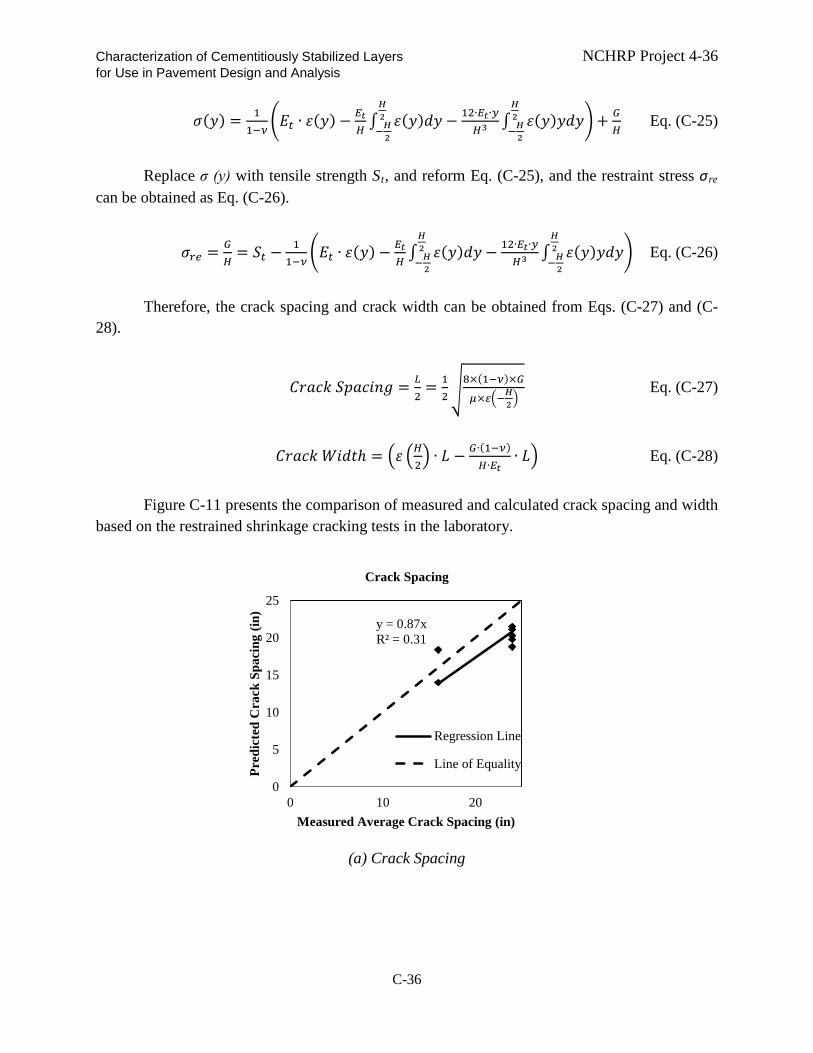
Characterization of Cementitiously Stabilized Layers NCHRP Project 4-36 for Use in Pavement Design and Analysis
𝜎𝜎(𝑦𝑦) = 11−𝜈𝜈
�𝐸𝐸𝑓𝑓 ∙ 𝜀𝜀(𝑦𝑦) − 𝐸𝐸𝑡𝑡𝐸𝐸 ∫ 𝜀𝜀(𝑦𝑦)𝑑𝑑𝑦𝑦
𝐻𝐻2−𝐻𝐻2
− 12∙𝐸𝐸𝑡𝑡∙𝑦𝑦𝐸𝐸3 ∫ 𝜀𝜀(𝑦𝑦)𝑦𝑦𝑑𝑑𝑦𝑦
𝐻𝐻2−𝐻𝐻2
�+ 𝐺𝐺𝐸𝐸
Eq. (C-25)
Replace σ (y) with tensile strength St, and reform Eq. (C-25), and the restraint stress σre can be obtained as Eq. (C-26).
𝜎𝜎𝑐𝑐𝑒𝑒 = 𝐺𝐺𝐸𝐸
= 𝑆𝑆𝑓𝑓 −1
1−𝜈𝜈�𝐸𝐸𝑓𝑓 ∙ 𝜀𝜀(𝑦𝑦) − 𝐸𝐸𝑡𝑡
𝐸𝐸 ∫ 𝜀𝜀(𝑦𝑦)𝑑𝑑𝑦𝑦𝐻𝐻2−𝐻𝐻2
− 12∙𝐸𝐸𝑡𝑡∙𝑦𝑦𝐸𝐸3 ∫ 𝜀𝜀(𝑦𝑦)𝑦𝑦𝑑𝑑𝑦𝑦
𝐻𝐻2−𝐻𝐻2
� Eq. (C-26)
Therefore, the crack spacing and crack width can be obtained from Eqs. (C-27) and (C-
28).
𝐶𝐶𝑜𝑜𝑡𝑡𝑐𝑐𝑘𝑘 𝑆𝑆𝑆𝑆𝑡𝑡𝑐𝑐𝑚𝑚𝑚𝑚𝐿𝐿 = 𝐿𝐿2
= 12�
8×(1−𝜈𝜈)×𝐺𝐺
𝜇𝜇×𝜀𝜀�−𝐻𝐻2� Eq. (C-27)
𝐶𝐶𝑜𝑜𝑡𝑡𝑐𝑐𝑘𝑘 𝑊𝑊𝑚𝑚𝑑𝑑𝑡𝑡ℎ = �𝜀𝜀 �𝐸𝐸2� ∙ 𝐿𝐿 − 𝐺𝐺∙(1−𝜈𝜈)
𝐸𝐸∙𝐸𝐸𝑡𝑡∙ 𝐿𝐿� Eq. (C-28)
Figure C-11 presents the comparison of measured and calculated crack spacing and width
based on the restrained shrinkage cracking tests in the laboratory.
(a) Crack Spacing
y = 0.87x R² = 0.31
0
5
10
15
20
25
0 10 20
Pred
icte
d C
rack
Spa
cing
(in)
Measured Average Crack Spacing (in)
Crack Spacing
Regression Line
Line of Equality
C-36

Characterization of Cementitiously Stabilized Layers NCHRP Project 4-36 for Use in Pavement Design and Analysis
(b) Crack Width
Figure C-11. Comparison of Measured and Predicted Crack Spacing and Width from Lab Tests
However, the predicted crack spacing and width obtained using the aforementioned
models that are based on a purely mechanical approach do not match the field shrinkage crack data. Therefore, it was decided to develop an empirical shrinkage model based on dimensional analysis. Details about dimensional analysis are introduced by Andrew (2007). The calibration of the shrinkage cracking models is based on the restrained shrinkage cracking test results obtained from the laboratory and field pavement data. Because the stabilized fine material and stabilized coarse material show different shrinkage properties according to Kodikara and Chakrabarti (2001), the calibration was carried out for fine host material and coarse host material separately with different parameter constraints. Eqs. (C-29) and (C-30) show these crack spacing and crack width models, respectively. Figures C-12 and C-13 present the comparison of the predicted and measured shrinkage crack spacing results for the CSL for stabilized fine and coarse materials, respectively. Figures C-14 and C-15 present the comparison of the predicted and measured shrinkage crack width results for the stabilized fine and coarse materials, respectively. Tables C-17 and C-18 present the model parameters for the crack spacing and width models, respectively.
log (𝐿𝐿
𝐸𝐸) = �� 𝜇𝜇
𝜌𝜌∙𝐸𝐸∙𝑓𝑓−2�𝑙𝑙1∙ (𝑐𝑐%)𝑙𝑙2 ∙ �𝜔𝜔
𝜌𝜌�𝑙𝑙3∙ (∆𝑇𝑇 ∙ 𝐶𝐶𝐶𝐶𝑇𝑇𝐸𝐸)𝑙𝑙4 ∙ � 𝑈𝑈𝐶𝐶𝐶𝐶28
𝜌𝜌∙𝐸𝐸2∙𝑓𝑓−2�𝑙𝑙5∙ (𝑅𝑅𝑅𝑅%)𝑙𝑙6 ∙ �𝜀𝜀𝑡𝑡𝑡𝑡𝑡𝑡
𝜀𝜀𝑢𝑢𝑢𝑢𝑡𝑡�𝑙𝑙7∙ �𝜀𝜀𝑡𝑡𝑡𝑡𝑡𝑡∙𝐸𝐸𝑡𝑡
𝐶𝐶𝐼𝐼𝐷𝐷𝐼𝐼�𝑙𝑙8� ∙ 𝑙𝑙9 Eq. (C-29)
W = �� 𝜇𝜇
𝜌𝜌∙𝐸𝐸∙𝑓𝑓−2�𝑤𝑤1∙ (𝑐𝑐%)𝑤𝑤2 ∙ �𝜔𝜔
𝜌𝜌�𝑤𝑤3∙ (∆𝑇𝑇 ∙ 𝐶𝐶𝐶𝐶𝑇𝑇𝐸𝐸)𝑤𝑤4 ∙ � 𝑈𝑈𝐶𝐶𝐶𝐶28
𝜌𝜌∙𝐸𝐸2∙𝑓𝑓−2�𝑤𝑤5∙ (𝑅𝑅𝑅𝑅%)𝑤𝑤6 ∙ �𝜀𝜀𝑡𝑡𝑡𝑡𝑡𝑡
𝜀𝜀𝑢𝑢𝑢𝑢𝑡𝑡�𝑤𝑤7∙ �𝜀𝜀𝑡𝑡𝑡𝑡𝑡𝑡∙𝐸𝐸𝑡𝑡
𝐶𝐶𝐼𝐼𝐷𝐷𝐼𝐼�𝑤𝑤8� ∙ 𝑤𝑤9 Eq. (C-30)
where,
L = crack spacing, in. W = crack width, in.
y = 1.04x R² = 0.31
0.00
0.05
0.10
0.15
0.20
0.25
0.30
0.00 0.10 0.20 0.30
Pred
icte
d C
rack
Wid
th (i
n)
Measured Average Crack Width (in)
Crack Width
Regression LineLine of Equality
C-37

Characterization of Cementitiously Stabilized Layers NCHRP Project 4-36 for Use in Pavement Design and Analysis
H = thickness of CSL, in. μ = coefficient of friction, psi/in. ρ = dry density, lb/ft3 t = age when crack survey conducted, days c% = calcium content, % ω = water content, lb/ft3 ∆T = average daily maximum temperature variation, °F COTE = coefficient of thermal expansion, /°F UCS28 = 28-day UCS at 68°F and 100% RH RH = atmospheric relative humidity, % 𝜀𝜀𝑓𝑓𝑡𝑡𝑡𝑡 = shrinkage on the top surface 𝜀𝜀𝑐𝑐𝑙𝑙𝑓𝑓 = ultimate drying shrinkage SIDT = IDT strength, calculated from IDT strength growth model, psi Et = IDT modulus, calculated from IDT modulus growth model, psi li = regression parameters for crack spacing model, i = 0, 1, 2, 3, 4, 5, 6, 7 wi = regression parameters for crack width model, i = 0, 1, 2, 3, 4, 5, 6, 7.
Figure C-12. Comparison of Predicted and Measured CSL Shrinkage Crack Spacing
Results for Stabilized Fine Materials
0
2
4
6
0 2 4 6
Pred
icte
d lo
g(L
) (in
)
Measured log(L) (in)
Measured-Predicted log(L) (Fine Materials)
Regression Line
Line of Equality
C-38

Characterization of Cementitiously Stabilized Layers NCHRP Project 4-36 for Use in Pavement Design and Analysis
Figure C-13. Comparison of Predicted and Measured CSL Shrinkage Crack Spacing
Results for Stabilized Coarse Materials
Figure C-14. Comparison of Predicted and Measured CSL Shrinkage Crack Width Results
for Stabilized Fine Materials
0
1
2
3
0 1 2 3
Pred
icte
d lo
g(L
) (in
)
Measured log(L) (in)
Measured-Predicted log(L) (Coarse Materials)
Regression Line
Line of Equality
0
0.1
0.2
0.3
0 0.1 0.2 0.3
Pred
icte
d W
(in)
Measured W (in)
Measured-Predicted W (Fine Materials)
Regression Line
Line of Equality
C-39

Characterization of Cementitiously Stabilized Layers NCHRP Project 4-36 for Use in Pavement Design and Analysis
Figure C-15. Comparison of Predicted and Measured CSL Shrinkage Crack Width Results
for Stabilized Coarse Materials
Table C-17. Field-Calibrated Parameters of CSL Shrinkage Crack Spacing Model for Fine and Coarse Host Materials
Parameters Fine Materials Parameters Coarse Materials l1 (<0) -1.19E-01 l1 (<0) 0 l2 (>0) 5.98E-01 l2 (<0) -1.39E-01 l3 (<0) -7.78E-01 l3 (<0) -1.36E-04 l4 (<0) 0 l4 (<0) 0 l5 (>0) 0 l5 (<0) -1.46E-01 l6 (>0) 0 l6 (>0) 2.11E+00 l7 (<0) -2.20E-03 l7 (<0) 0 l8 (<0) -2.53E-01 l8 (<0) 0 l9 8.74E+00 l9 3.85E+00
( ) contains the parameter constraints.
0
0.02
0.04
0.06
0.08
0.1
0 0.05 0.1
Pred
icte
d W
(in)
Measured W (in)
Measured-Predicted W (Coarse Materials)
Regression Line
Line of Equality
C-40

Characterization of Cementitiously Stabilized Layers NCHRP Project 4-36 for Use in Pavement Design and Analysis Table C-18. Field-Calibrated Parameters of CSL Shrinkage Crack Width Model for Fine
and Coarse Host Materials Parameters Fine Materials Parameters Coarse Materials w1 (>0) 7.81E-03 w1 (>0) 0 w2 (<0) -1.20E+00 w2 (>0) 0 w3 (>0) 7.67E-01 w3 (>0) 1.34E+00 w4 (>0) 0 w4 (>0) 1.76E-05 w5 (<0) 0 w5 (>0) 3.63E-02 w6 (<0) 0 w6 (<0) 0 w7 (>0) 6.69E-01 w7 (>0) 0 w8 (>0) 4.71E-01 w8 (>0) 5.36E-02 w9 8.63E-04 w9 1.78E-01
( ) contains the parameter constraints. Durability Models
In the field, the CSL are subjected to weathering, such as wetting and drying and freezing
and thawing, which must be characterized. Introduction to Durability Models
Currently, there is no durability model for CSL in the MEPDG. The team has identified
one durability model for concrete specimens that are subjected to freeze-thaw cycles, which has the potential to be used for CSL. The revised durability model is as follows (Wei et al. 2003).
𝐸𝐸(𝑁𝑁) = 𝐸𝐸0𝑒𝑒𝑘𝑘1𝐼𝐼(∆𝐿𝐿𝐿𝐿 )2𝑁𝑁
3 Eq. (C-31)
where E = modulus of CSM after N cycles of freeze-thaw E0 = modulus of CSM before freeze-thaw cycles k1 = regression constant T = duration of one freeze-thaw cycle ∆L = increase of specimen length after freezing L = original length of specimen N = number of freeze-thaw cycles.
Khoury and Zaman (2008) developed an empirical model for CSL subjected to wet-dry
cycles, as follows. 𝑀𝑀𝑐𝑐 = 𝐴𝐴 × 𝐵𝐵𝑊𝑊𝑊𝑊𝐶𝐶 × 𝐶𝐶𝐶𝐶𝐶𝐶𝐶𝐶𝐶𝐶𝑅𝑅 × 𝐷𝐷𝑊𝑊𝐶𝐶𝑅𝑅 × 𝐸𝐸𝜎𝜎3 × 𝑅𝑅𝜎𝜎𝑑𝑑 Eq. (C-32)
C-41

Characterization of Cementitiously Stabilized Layers NCHRP Project 4-36 for Use in Pavement Design and Analysis where
A, B, C, D, E, F = regression coefficients WDC = number of wet-dry cycles CSAFR = ratio of free lime to SAF (silica, alumina, and ferric oxide) DMR = ratio of maximum dry density to optimum moisture content σ3 = confining pressure σd = deviatoric stress.
Evaluation of Durability Models
The durability model shown in Eq. (C-31) requires the length change of the specimen,
which is only applicable to laboratory experiments, not field pavements. The durability model shown in Eq. (C-32) requires the chemical composition of the soils, which may not be available. Therefore, wet-dry and freeze-thaw durability models are developed in this study, as shown in Eq. (C-33), but with different model parameters for the wet-dry and freeze-thaw models.
𝑈𝑈𝐶𝐶𝑆𝑆(𝑁𝑁) = 𝑈𝑈𝐶𝐶𝑆𝑆𝑐𝑐𝑐𝑐𝑐𝑐𝑐𝑐𝑒𝑒𝑛𝑛𝑓𝑓 �𝑚𝑚1/𝑙𝑙𝑛𝑛(𝑈𝑈𝐶𝐶𝐶𝐶28)1+𝑒𝑒(𝑠𝑠1 𝑁𝑁) + 1 − 𝑛𝑛1 /𝑙𝑙𝑛𝑛(𝑈𝑈𝐶𝐶𝐶𝐶28)
2� Eq. (C-33)
where
UCS(N) = UCS after N cycles of freeze-thaw or wet-dry, psi UCScurrent = UCS before freeze-thaw or wet-dry cycle, at age t in months (considering the
strength growth from 28 days to time of freeze-thaw or wet-dry cycle), psi UCS28 = 28-day UCS, psi N = number of freeze-thaw or wet-dry cycles m1, n1 = regression parameters.
Table C-19 presents the model parameters for the wet-dry and freeze-thaw models based
on the laboratory test results. Figures C-16 and C-17 present the comparisons of the predicted and measured UCS values for the wet-dry and freeze-thaw models, respectively.
C-42

Characterization of Cementitiously Stabilized Layers NCHRP Project 4-36 for Use in Pavement Design and Analysis
Figure C-16. Comparison of Predicted UCS and Measured UCS Values after Wet-Dry
Tests
Figure C-17. Comparison of Predicted UCS and Measured UCS Values after Freeze-Thaw
Tests
Table C-19. Regression Parameters of Durability Models
Wet-Dry m1 2.58
n1 0.62
Freeze-Thaw m1 6.68
n1 0.93
y = 0.99x R² = 0.99
0
500
1000
1500
2000
0 500 1000 1500 2000
Pred
icte
d U
CS
(psi
)
Measured UCS (psi)
Comparison of Predicted and Measured UCS after Wet-Dry Cycles
Line of Equality
Regression Line
y = 0.98x R² = 0.90
0
100
200
300
400
500
0 100 200 300 400 500
Pred
icte
d U
CS
(psi
)
Measured UCS (psi)
Comparison of Predicted and Measured UCS after Freeze-Thaw Cycles
Regression Line
Line of Equality
C-43

Characterization of Cementitiously Stabilized Layers NCHRP Project 4-36 for Use in Pavement Design and Analysis Erosion Models
Introduction to Current Erosion Models
A few models are available for estimating the erosion of the base/subbase in concrete
pavement, as follows.
(a) Markow (1984) model An empirical model (Markow 1984) that is based on the AASHTO road test data relates
erosion to slab thickness, equivalent single-axle loads (ESALs), and subbase drainage conditions. The model is simple but does not consider many important factors. The pumping index indicates the potential of erosion, which increases with the increase in the cumulative number of ESALs and with a decrease in drainage, but decreases quickly with an increase in slab thickness. A drainage adjustment factor is considered based on subbase permeability.
𝑃𝑃𝑖𝑖 = 𝑚𝑚∑𝐸𝐸𝑆𝑆𝐴𝐴𝐿𝐿𝑓𝑓𝑑𝑑 Eq. (C-34) log𝑚𝑚 = 1.07 − 0.34 𝐷𝐷 Eq. (C-35)
where
Pi = pumping index D = slab thickness, in. ESAL = equivalent 80 kN (18,000 lb) single-axle loads fd = drainage adjustment factor
= 0.2 for good drainage (k = 10,000 ft/day) = 0.6 for fair drainage (k = 100 ft/day) = 1.0 for poor drainage (k = 0.1 ft/day)
k = subbase permeability.
(b) Larralde (1984) model Another empirical model (Larralde 1984) that is based on the AASHTO road test data
relates erosion to the amount of deformation energy imposed by the application of the load. The deformation energy is computed using finite element modeling. A pumping index is normalized to eliminate the effects of slab length and reinforcement. The model shown in Eq. (C-36) is empirical in nature and consequently does not consider many important facts related to erosion.
𝑁𝑁𝑃𝑃𝑁𝑁 = 𝑒𝑒𝑥𝑥𝑆𝑆 �−2.884 + 1.652 ∙ 𝑙𝑙𝑜𝑜𝐿𝐿 �∑𝐸𝐸𝐶𝐶𝐶𝐶𝐿𝐿.𝑊𝑊𝐸𝐸10,000
�� Eq. (C-36)
where
C-44

Characterization of Cementitiously Stabilized Layers NCHRP Project 4-36 for Use in Pavement Design and Analysis
NPI = normalized pumping index of volume of pumped material, in.3 ESAL = equivalent 80 kN (18,000 lb) single-axle loads DE = deformation energy per one application of ESAL
= log(DE) = 3.5754 – 0.3323 D D = slab thickness, in.
(c) Rauhut (1982) model In the Rauhut (1982) model, the level of pumping damage, which is based on nonlinear
regression analysis of the Concrete Pavement Evaluation System (COPES) database, is related empirically to many comprehensive factors, such as precipitation, drainage, subbase type (stabilized or not), subgrade type (soil type), load transfer, slab thickness, freezing index, the Thornthwaite moisture index, and traffic. Eq. (C-37) is separated for jointed plain concrete pavement (JPCP) in Eqs. (C-38) and (C-39) and for jointed reinforced concrete pavement (JRCP) in Eqs. (C-41) and (C-42).
𝐿𝐿 = �𝐸𝐸𝐶𝐶𝐶𝐶𝐿𝐿𝜌𝜌�𝛽𝛽
Eq. (C-37)
JPCP
𝑙𝑙𝑚𝑚𝑙𝑙 = 1.39 ∙ 𝐷𝐷𝑅𝑅𝐴𝐴𝑁𝑁𝑁𝑁 + 4.13 Eq. (C-38)
𝛽𝛽 = 0.772(𝑊𝑊−2.3)1.61
𝑃𝑃𝑃𝑃𝑇𝑇𝑁𝑁+ 0.0157. 𝐽𝐽𝐿𝐿𝑇𝑇𝑆𝑆.𝐷𝐷 + 0.104. 𝑆𝑆𝑇𝑇𝐴𝐴𝐵𝐵 + 0.17.𝐷𝐷𝑅𝑅𝐴𝐴𝑁𝑁𝑁𝑁 + 0.137. 𝑆𝑆𝐶𝐶𝑁𝑁𝐿𝐿𝑇𝑇𝑆𝑆𝑃𝑃 −
0.247 Eq. (C-39)
JRCP 𝑙𝑙𝑚𝑚𝑙𝑙 = 1.028 ∙ 𝑆𝑆𝑇𝑇𝐴𝐴𝐵𝐵 + 0.0004966 ∙ 𝐷𝐷3.47 − 0.01248 ∙ 𝑅𝑅𝑅𝑅𝑁𝑁𝑁𝑁𝐷𝐷𝐸𝐸𝐹𝐹 + 1.667 ∙ 𝐶𝐶𝐵𝐵𝑅𝑅 + 5.476 Eq. (C-40) 𝛽𝛽 = −0.01363 ∙ 𝐷𝐷𝑀𝑀𝐶𝐶𝑁𝑁𝑆𝑆𝑇𝑇 + 0.02527 ∙ 𝐷𝐷 − 0.423 Eq. (C-41)
where
g = amount of distress as a fraction of pumping level 3 (severe) DRAIN = 0 is no underdrainage, 1 is underdrainage PPTN = average annual precipitation (cm) JLTS = 0 is undoweled, 1 is doweled STAB = 0 is unstabilized subbase, 1 is stabilized subbase SOILTYP = 0 is granular foundation soil, 1 is coarse foundation soil DMOIST = Thornthwaite moisture index FRINDEX = freezing index
C-45

Characterization of Cementitiously Stabilized Layers NCHRP Project 4-36 for Use in Pavement Design and Analysis
CBR = California bearing ratio of foundation soil D = slab thickness.
(d) Van Wijk (1985) model Eqs. (C-42) and (C-43) include factors derived from field data to make improvements to
the Larralde model (1984) to predict the volume of eroded material as a function of the deformation energy produced by traffic. The effects of many factors, such as subbase and subgrade type, drainage, load transfer, and climate conditions, on pumping are considered in this model (Van Wijk 1985). Because this model is empirical in nature, its application is limited to the variable ranges included in the database. (Note that Eq. (C-43) is the same as Eq. (C-37) but with a modification factor F.)
𝑃𝑃 = 36.67 ∙ 𝑁𝑁𝑃𝑃𝑁𝑁 Eq. (C-42)
𝑁𝑁𝑃𝑃𝑁𝑁 = 𝑅𝑅 ∙ 𝑒𝑒𝑥𝑥𝑆𝑆 �−2.884 + 1.652 ∙ 𝑙𝑙𝑜𝑜𝐿𝐿 �∑𝐸𝐸𝐶𝐶𝐶𝐶𝐿𝐿∙𝑊𝑊𝐸𝐸10,000
�� Eq. (C-43)
where
P = volume of pumped material (ft3/mile) NPI = normalized pumping index (in.3) DE = deformation energy per application (in.-lb)
Log (DE) = 3.5754 – 0.3323D D = slab thickness F = fJPCP if nonreinforced PCC, fJRCP if reinforced PCC
𝑓𝑓𝐽𝐽𝑃𝑃𝐶𝐶𝑃𝑃 = 𝑓𝑓𝑠𝑠𝑠𝑠𝑙𝑙 ∙ 𝑓𝑓𝑑𝑑 ∙ 𝑓𝑓𝑡𝑡𝑐𝑐𝑒𝑒𝑐𝑐 ∙ 𝑓𝑓𝑠𝑠𝑔𝑔 fsbl = subbase adjustment factor = 1 if unstabilized,
= 0.65+0.18 log(ΣESAL) if stabilized fd = drainage adjustment factor
= 1, poor drainage 0.91 +0.12 log(ΣESAL) – 0.03 D, fair drainage 0.68 +0.15 log(ΣESAL) – 0.04 D, good drainage 0.01, excellent drainage
flt = load transfer adequacy adjustment factor 1, with dowel 1.17 - 0.68 log(ΣESAL) – 0.07 D, without dowel
fprec = rainfall adjustment factor 0.89 + 0.26 log(ΣESAL) – 0.07 D, dry climates 0.96 + 0.06 log(ΣESAL) + 0.02 D, wet climates
fsg = subgrade adjustment factor 1, granular subgrade
C-46

Characterization of Cementitiously Stabilized Layers NCHRP Project 4-36 for Use in Pavement Design and Analysis
0.57 + 0.21 log(ΣESAL), coarse subgrade fJRCP = fsb2.fe fsb2 =subbase adjustment factor
1 is unstabilized 0.91 - 0.02 log(ΣESAL), coarse subgrade
fe = adjustment for climate 0.011 + 0.003 log(ΣESAL) – 0.001D, dry, warm climates 1.44 -0.03 log(ΣESAL) – 0.06D, wet, warm climates 1.04- 0.32 log(ΣESAL) – 0.08 D, dry, cold climates 0.54 - 0.85 log(ΣESAL) – 0.19 D, wet, cold climates.
(e) Jeong and Zollinger (2001) model A mechanistic empirical model is developed using the water-induced shear stress model
proposed by Jeong and Zollinger (2001), as shown in Eq (C-44). Key factors, such as vehicle load and speed, load transfer, number of applications, and climatic conditions, are included in the model to predict erosion. The erosion potential increases with a high initial edge gap and lift-off distance due to the effect of upward curling at the slab corners and edges, which induces shear stress on the base layer by pumping out the trapped water. The magnitude of the shear stress depends on the dynamic viscosity of the water, which is governed by the water temperature and the rate of slab deflection. Higher slab deflection velocity and lower viscosity of water result in more erosion of the base. An effective load transfer cuts down the erosion rate, as detailed in the performance equation. The accuracy of the model should be calibrated using performance data such as those available in the Long-Term Pavement Performance (LTPP) database. This model can be improved by considering abrasive erosion caused by friction between the concrete and subbase layers.
𝜐𝜐 = 𝜐𝜐0𝑒𝑒𝑥𝑥𝑆𝑆 �−�𝜌𝜌𝑁𝑁𝑠𝑠�𝑚𝑚� Eq. (C-44)
where
υ0 = ultimate erosion depth (L) N = number of axle loads per load group ρ = calibration coefficient based on local performance a = a′αf
a′ = environmental calibration coefficient αf = inverse of the rate of void development
=�𝜕𝜕𝜐𝜐𝑠𝑠𝜕𝜕𝑓𝑓�−1
= �𝑙𝑙𝑡𝑡𝑔𝑔−1(𝑚𝑚𝑚𝑚𝜏𝜏+𝑠𝑠𝑚𝑚)
𝜇𝜇𝑏𝑏�−1
= � 𝛽𝛽𝜇𝜇𝑏𝑏�−1
τ = shear stress = 𝜂𝜂𝐵𝐵𝛿𝛿𝑣𝑣𝑡𝑡𝑠𝑠𝑑𝑑
�1 − 𝐿𝐿𝑇𝑇𝐸𝐸100
�
C-47

Characterization of Cementitiously Stabilized Layers NCHRP Project 4-36 for Use in Pavement Design and Analysis
η = dynamic viscosity (FL-2T) = �2056.82 + 10.56𝑇𝑇 − 284.93√𝑇𝑇 − 265.02𝑒𝑒−𝑇𝑇�10−6
T = water temperature (°C)
B = 𝑉𝑉𝑧𝑧𝑠𝑠𝑐𝑐𝑚𝑚𝑚𝑚𝑠𝑠 + 6𝑉𝑉𝑧𝑧𝑠𝑠 �𝑠𝑠𝑖𝑖𝑛𝑛𝑠𝑠2
+ 𝑐𝑐𝑡𝑡𝑠𝑠2𝑠𝑠𝑠𝑠𝑖𝑖𝑛𝑛𝑠𝑠
� (L/T)
δvoid = void space below slab for water movement
θ = slab angle = tan−1 �𝑧𝑧0𝑠𝑠�
z0 = edge gap (L) = (1+𝜈𝜈)𝐸𝐸
Δ𝜖𝜖𝑓𝑓𝑡𝑡𝑓𝑓𝑙𝑙2
𝑉𝑉𝑧𝑧𝑠𝑠 = 𝛿𝛿𝑠𝑠𝑠𝑠𝑡𝑡𝑠𝑠/𝑉𝑉𝑠𝑠
𝛿𝛿𝑖𝑖𝑛𝑛𝑓𝑓 = 𝑃𝑃𝑠𝑠8𝑘𝑘𝑙𝑙
�1 + �0.3665𝑙𝑙𝑜𝑜𝐿𝐿 �𝑚𝑚𝐿𝐿𝑙𝑙� − 0.2174 �𝑚𝑚𝐿𝐿
𝑙𝑙�2��
aL = loaded radius (L) Pi = axle load (F) s = slab lift-off distance (L) = √2l(γ -1)
𝛾𝛾 = �𝑧𝑧0𝑤𝑤0
𝑤𝑤0 = 𝜌𝜌𝐸𝐸𝑘𝑘
Evaluation of Erosion Model
The above models are either empirical or difficult to implement. Most importantly, in the field, the effects of top compression fatigue and erosion are combined. Therefore, the cyclic impact erosion test that includes both top compression fatigue and the effects of erosion is developed in this study. Details about the test method are introduced in Appendix B in the section entitled Erodibility. The fatigue-erosion model is modified from Eq. (C-10) and is expressed as Eq. (C-45) and called the top-down compressive-fatigue-erosion model.
𝑙𝑙𝑜𝑜𝐿𝐿𝑁𝑁𝑓𝑓𝑐𝑐 = 𝑘𝑘4𝑙𝑙𝑜𝑜𝐿𝐿 �𝜌𝜌𝜔𝜔� �1 − 𝜎𝜎𝑐𝑐
𝑘𝑘5 𝑈𝑈𝐶𝐶𝐶𝐶� Eq. (C-45)
where
Nfc = top-down compressive-fatigue-erosion life, defined as the number of cycles when the modulus drops to 50% of the initial modulus
ρ = maximum dry density, lb/ft3
ω = optimum moisture content, % σc = compressive stress applied on the top of specimen, psi UCS = current unconfined compressive strength, psi k4, k5 = regression parameters.
C-48

Characterization of Cementitiously Stabilized Layers NCHRP Project 4-36 for Use in Pavement Design and Analysis
The incorporation of maximum dry density and optimum moisture content in the model differentiates the susceptibility of the fine and coarse materials. The modulus reduction model for top-down compressive-fatigue-erosion is based on Eq. (C-12), but uses different parameters. Table C-20 presents the model parameters that are based on laboratory CIE tests. Figure C-18 presents the comparison of measured and predicted fatigue life data.
Table C-20. Parameters for Top-Down Compressive-Fatigue-Erosion Model Model Parameter
Top-Down Compressive-Fatigue-Erosion Life
k4 2.79
k5 3.39
Top-Down Compressive-Fatigue-Erosion Modulus
Reduction
m2 6.77
n2 1.99
Figure C-18. Comparison of Measured and Predicted Modulus Values for Top-Down
Compressive-Fatigue-Erosion Model The performance models were developed based on laboratory experiments. However,
these models need to be calibrated using field data. Typically, there is a discrepancy between laboratory results and field results.
y = 0.94x R² = 0.15
0
1
2
3
4
5
0 1 2 3 4 5
Pred
icte
d lo
g(N
fc)
Measured log(Nfc)
log(Nf)
Regression Line
Lime of Equality
C-49

Characterization of Cementitiously Stabilized Layers NCHRP Project 4-36 for Use in Pavement Design and Analysis REFERENCES
Andrew, C. P. 2007. Dimensional Analysis and Intelligent Experimentation. Singapore: World Scientific Publishing Co. Pte. Ltd.
Applied Research Associates, Inc. (ARA). 2004. Guide for Mechanistic-Empirical Design for New and Rehabilitated Pavement Structures. NCHRP 1-37A Final Report, National Cooperative Highway Research Program, Transportation Research Board, National Research Council (March).
Carteret, R. D., H. Chen, L. Comport, D. Firth, and A. Howard. 2009. Cost-effective Structural Treatments for Rural Highways--Cemented Materials. Austroads Project No. TT1359 Interim Report (June).
Corte, J. F. and M. T. Goux. 1996. Design of Pavement Structures: the French Technical Guide. Transportation Research Record 1539: 116-124.
De Beer, M. 1990. Aspects of the Design and Behaviour of Road Structures Incorporating Lightly Cementitious Layers. Ph.D. Dissertation, Faculty of Engineering, University of Pretoria, Pretoria (February).
Dempsey, B. J., D. Janssen, J. Thomas, P. Frey, A. Ioannides, and R. Elliott. 1984. Development of a Preliminary ALRS Stabilized Material Pavement Analysis System (SPAS). Final Report, Engineering and Services Laboratory, Air Force Engineering and Services Center.
Freeme, C. R., J. H. Maree, and A. W. Viljoen. 1982. Mechanistic Design of Asphalt Pavements and Verification Using the Heavy Vehicle Simulator. Proceedings of the Fifth International Conference on Structural Design of Asphalt Pavements, Delft, Netherlands, University of Michigan, Ann Arbor, Michigan, Vol.1: 156-73.
George, K. P. 1968. Cracking In Cement-Treated Bases and Means for Minimizing It. Highway Research Record 255: 59-71.
Jeong, J. and D. Zollinger. 2001. Characterization of Stiffness Parameters in Design of Continuously Reinforced and Jointed Pavements. Transportation Research Record 1778, Transportation Research Board, National Research Council, Washington, DC: 54-63.
Khoury, N. N. and M. M. Zaman. 2007. Durability of Stabilized Base Courses Subjected to Wet–Dry Cycles. International Journal of Pavement Engineering 8 (4) (December): 265–276.
Kodikara, J. and S. Chakrabarti. 2001. Shrinkage Behaviour of Cemented Materials as Applicable to In Situ Pavement Stabilisation.
Larralde, J. 1984. Structural Analysis of Rigid Pavements with Pumping. Ph.D. Thesis, Purdue University, West Lafayette, Indiana (December).
Litwinowicz, A. and A. N. Brandon. 1994. Dynamic Flexure Testing for Prediction of Cement–treated Pavement Life. Proceedings of the 17th Australian Road Research Board
C-50

Characterization of Cementitiously Stabilized Layers NCHRP Project 4-36 for Use in Pavement Design and Analysis
Conference, Gold Coast, Queensland 17 (2), Australian Road Research Board, Vermont South, Victoria: 229-247.
Markow, M. J. and B. D. Brademeyer. 1984. EAROMAR Version 2. Final Technical Report, FHWA/RD-82/086 (April).
Mokarem, D. W., R. M. Meyerson, and R. E. Weyers. 2003. Development of Concrete Shrinkage Performance Specifications. Virginia Transportation Research Council (August).
National Association of Australian State Roads. 1987. Guide to Stabilisation in Roadworks.
National Lime Association. 2006. Technical Brief: Mixture Design and Testing Procedures for Lime Stabilized Soil (October).
Nussbaum, P. J. and L. D. Childs. 1975. Repetitive Load Tests of Concrete Slabs on Cement-Treated Subbases. Portland Cement Association.
Otte, E. 1978. A Structural Design Procedure for Cement-Treated Layers In Pavements. Ph.D. Dissertation, Faculty of Engineering, University of Pretoria.
Rauhut, J. B., R. L. Lytton, and M. I. Darter. 1982. Pavement Damage Functions for Cost Allocation: Vol. 1, Damage Functions and Load Equivalency Factors. FHWA/RD-82/126 (July).
Scullion, T., J. Uzan, S. Hilbrich, and P. Chen. 2008. Thickness Design Systems for Pavements Containing Soil-Cement Bases. PCA R&D SN2863.
Theyse, H. L., M. De Beer, J. Prozzi, and C. J. Semmelink. 1995. TRH4 Revision Updating the Transfer Functions for the South.
Van Wijk, A. J. 1985. Rigid Pavement Pumping: (1) Subbase Erosion, (2) Economic Modeling. Information Report, Purdue and Indiana State Highway Commission JHRP (May 16).
Wei, J., X. Wu, and X. Zhao. 2003. A Model for Concrete Durability Degradation in Freeze-thawing Cycles. Acta Mechanica Solida Sinica 16 (4): 353-358.
Westergaard, H. M. 1927. Analysis of Stresses in Concrete Pavements due to Variations of Temperature. Highway Research Record 6: 201-215.
Yeo, Y. 2008. Fatigue Performance of Cemented Materials under Accelerated Loading – Influence of Vertical Loading on the Performance of Unbound and Cemented Materials. Austroads (August).
Zhang, J. and V. Li. 2001. Influence of Supporting Base Characteristics on Shrinkage-Induced Stresses in Concrete Pavements. Journal of Transportation Engineering 127 (6) (November/December).
C-51

Characterization of Cementitiously Stabilized Layers NCHRP Project 4-36 for Use in Pavement Design and Analysis
Appendix D. Evaluation of FWD Backcalculation
D-1

Characterization of Cementitiously Stabilized Layers NCHRP Project 4-36 for Use in Pavement Design and Analysis
Introduction
Because cementitiously-stabilized layers (CSL) typically are used as base or subbase layers, the performance of CSL in the field cannot be measured directly or visualized. The field cores of CSL are not available for characterization in this study. Therefore, backcalculated modulus values obtained from falling weight deflectometer (FWD) tests, conducted in previous studies, are used in this study to detect the performance of CSL. The moduli of the CSL directly affect the pavement responses and performance of pavement in the field. However, it is well-known that FWD backcalculation is not a science and could cause significant error in backcalculated modulus values (Meier 1995, William 1999, Goktepe et al. 2006, Gopalakrishnan 2009). The accuracy of backcalculation of pavements that contain CSL was evaluated. Appraisal of Backcalculation Approach
In order to analyze the error associated with FWD backcalculation, commonly used FWD
backcalculation programs, such as Evercal, Modcomp 6, and MODULUS, are selected for this study. Table D-1 lists seven types of pavement structures that have different layer thicknesses and layer modulus values. For each pavement structure, pavement deflections at locations with distances of 8 in., 12 in., 18 in., 24 in., 36 in., and 60 in. from the loading center were determined using the EverStress program (developed by the Washington State Department of Transportation). In each of these pavement structures, the CSL modulus values vary from 50 ksi to 1000 ksi. These deflections are used to backcalculate the CSL modulus values, based on the backcalculation programs. The backcalculated CSL modulus values then are compared with the given CSL modulus values. The backcalculated modulus error is calculated by Eq. (D-1).
𝐵𝐵𝐵𝐵𝐵𝐵𝐵𝐵𝐵𝐵𝐵𝐵𝐵𝐵𝐵𝐵𝐵𝐵𝐵𝐵𝐵𝐵𝐵𝐵𝐵𝐵𝐵𝐵 𝑀𝑀𝑀𝑀𝐵𝐵𝐵𝐵𝐵𝐵𝐵𝐵𝑀𝑀 𝐸𝐸𝐸𝐸𝐸𝐸𝑀𝑀𝐸𝐸 = (𝐵𝐵𝐵𝐵𝐵𝐵𝐵𝐵𝐵𝐵𝐵𝐵𝐵𝐵𝐵𝐵𝐵𝐵𝐵𝐵𝐵𝐵𝐵𝐵𝐵𝐵𝐵𝐵 𝐶𝐶𝐶𝐶𝐶𝐶 𝑀𝑀𝑀𝑀𝐵𝐵𝐵𝐵𝐵𝐵𝐵𝐵𝑀𝑀−𝐺𝐺𝐺𝐺𝐺𝐺𝐵𝐵𝐺𝐺 𝐶𝐶𝐶𝐶𝐶𝐶 𝑀𝑀𝑀𝑀𝐵𝐵𝐵𝐵𝐵𝐵𝐵𝐵𝑀𝑀)
𝐺𝐺𝐺𝐺𝐺𝐺𝐵𝐵𝐺𝐺 𝐶𝐶𝐶𝐶𝐶𝐶 𝑀𝑀𝑀𝑀𝐵𝐵𝐵𝐵𝐵𝐵𝐵𝐵𝑀𝑀 100% Eq. (D-1)
Table D-2 shows the backcalculated CSL modulus errors for Evercal, Modcomp 6, and
MODULUS. The results indicate that all three FWD backcalculation programs result in large error for at least some of the pavement structures. Modcomp 6 shows more consistent backcalculation errors than Evercal for the structures simulated in this study. Structures E and F have relatively low backcalculation errors, probably because the CSL are thick. If a relatively thin stiff layer is sandwiched between weak layers, the backcalculation error could be large. Because the error is related to a specific pavement structure, it was decided to use the concept of modulus ratio. The CSL modulus ratio is defined by the ratio of each layer modulus to the original modulus for one pavement structure, simulating the change in CSL modulus values over time. Table D-2 presents the analysis results for the modulus ratios and associated errors. In most of the cases, the modulus ratio error is smaller than that of the backcalculated modulus error. Therefore, the modulus ratio concept is used based on the Modcomp 6 program.
D-2

Characterization of Cementitiously Stabilized Layers NCHRP Project 4-36 for Use in Pavement Design and Analysis
Table D-1. Assumed Pavement Structures in FWD Backcalculation Error Analysis
Pavement Type
Layer 1 Layer 2 Layer 3 Layer 4 Layer 5
Type Thickness (in.)
Modulus (psi) Type Thickness
(in.) Modulus
(psi) Type Thickness (in.)
Modulus (psi) Type Thickness
(in.) Modulus
(psi) Type Thickness (in.)
Modulus (psi)
A HMA 4.9 500000 Granular Base 8 50000 CSL 6 variable Granular
Subbase 12 70000 Sub-grade n/a 10000
B HMA 9.4 800000 Granular Base 11.8 35000 CSL 6 variable Granular
Subbase 11.5 30000 Sub-grade n/a 20000
C HMA 15.7 500000 CSL 6 variable Granular Subbase 9 50000 Subgrade n/a 30000
D HMA 7.2 900000 Granular Base 8.5 50000 Granular
Subbase 22.8 40000 CSL 12 variable Sub-grade n/a 30000
E HMA 7.2 900000 Granular Base 8.5 50000 CSL 12 variable Subgrade n/a 5000
F HMA 7.2 900000 Granular Base 8.5 50000 CSL 12 variable Subgrade n/a 5000
G HMA 4.0 600000 CSL 8 variable Subgrade n/a 25000
D-3
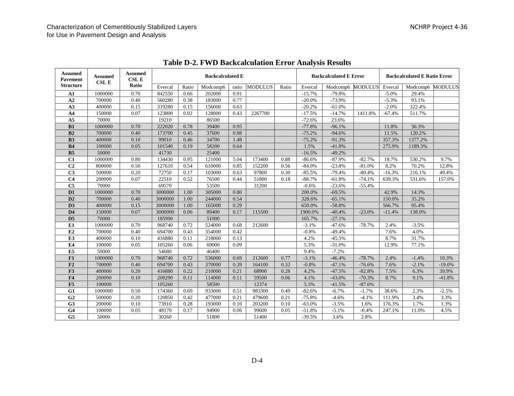
Characterization of Cementitiously Stabilized Layers NCHRP Project 4-36 for Use in Pavement Design and Analysis
Table D-2. FWD Backcalculation Error Analysis Results Assumed Pavement Structure
Assumed CSL E
Assumed CSL E Ratio
Backcalculated E Backcalculated E Error Backcalculated E Ratio Error
Evercal Ratio Modcomp6 ratio MODULUS Ratio Evercal Modcomp6 MODULUS Evercal Modcomp6 MODULUS A1 1000000 0.70 842550 0.66 202000 0.91 -15.7% -79.8% -5.0% 29.4% A2 700000 0.40 560280 0.38 183000 0.77 -20.0% -73.9% -5.3% 93.1% A3 400000 0.15 319280 0.15 156000 0.63 -20.2% -61.0% -2.0% 322.4% A4 150000 0.07 123800 0.02 128000 0.43 2267700 -17.5% -14.7% 1411.8% -67.4% 511.7% A5 70000 19210 86500 -72.6% 23.6% B1 1000000 0.70 222020 0.78 39400 0.95 -77.8% -96.1% 11.8% 36.3% B2 700000 0.40 173700 0.45 37600 0.88 -75.2% -94.6% 11.5% 120.2% B3 400000 0.10 99010 0.46 34700 1.48 -75.2% -91.3% 357.3% 1377.2% B4 100000 0.05 101540 0.19 58200 0.64 1.5% -41.8% 275.9% 1189.3% B5 50000 41730 25400 -16.5% -49.2% C1 1000000 0.80 134430 0.95 121000 5.04 173400 0.88 -86.6% -87.9% -82.7% 18.7% 530.2% 9.7% C2 800000 0.50 127610 0.54 610000 0.85 152200 0.56 -84.0% -23.8% -81.0% 8.2% 70.2% 12.8% C3 500000 0.20 72750 0.17 103000 0.63 97800 0.30 -85.5% -79.4% -80.4% -16.3% 216.1% 49.4% C4 200000 0.07 22510 0.52 76500 0.44 51800 0.18 -88.7% -61.8% -74.1% 639.3% 531.6% 157.0% C5 70000 69570 53500 31200 -0.6% -23.6% -55.4% D1 1000000 0.70 3000000 1.00 305000 0.80 200.0% -69.5% 42.9% 14.3% D2 700000 0.40 3000000 1.00 244000 0.54 328.6% -65.1% 150.0% 35.2% D3 400000 0.15 3000000 1.00 165000 0.29 650.0% -58.8% 566.7% 95.4% D4 150000 0.07 3000000 0.06 89400 0.17 115500 1900.0% -40.4% -23.0% -11.4% 138.9% D5 70000 185990 51000 165.7% -27.1% E1 1000000 0.70 968740 0.72 524000 0.68 212600 -3.1% -47.6% -78.7% 2.4% -3.5% E2 700000 0.40 694700 0.43 354000 0.42 -0.8% -49.4% 7.6% 4.0% E3 400000 0.10 416880 0.11 218000 0.13 4.2% -45.5% 8.7% 31.7% E4 100000 0.05 105260 0.06 69000 0.09 5.3% -31.0% 12.9% 77.1% E5 50000 54680 46400 9.4% -7.2% F1 1000000 0.70 968740 0.72 536000 0.69 212600 0.77 -3.1% -46.4% -78.7% 2.4% -1.4% 10.3% F2 700000 0.40 694700 0.43 370000 0.39 164100 0.32 -0.8% -47.1% -76.6% 7.6% -2.1% -19.0% F3 400000 0.20 416880 0.22 210000 0.21 68900 0.28 4.2% -47.5% -82.8% 7.5% 6.3% 39.9% F4 200000 0.10 208290 0.11 114000 0.11 59500 0.06 4.1% -43.0% -70.3% 8.7% 9.1% -41.8% F5 100000 105260 58500 12374 5.3% -41.5% -87.6% G1 1000000 0.50 174360 0.69 933000 0.51 983300 0.49 -82.6% -6.7% -1.7% 38.6% 2.3% -2.5% G2 500000 0.20 120850 0.42 477000 0.21 479600 0.21 -75.8% -4.6% -4.1% 111.9% 3.4% 3.3% G3 200000 0.10 73910 0.28 193000 0.10 203200 0.10 -63.0% -3.5% 1.6% 176.3% 1.7% 1.3% G4 100000 0.05 48170 0.17 94900 0.06 99600 0.05 -51.8% -5.1% -0.4% 247.1% 11.0% 4.5% G5 50000 30260 51800 51400 -39.5% 3.6% 2.8%
D-4

Characterization of Cementitiously Stabilized Layers NCHRP Project 4-36 for Use in Pavement Design and Analysis
REFERENCES
Goktepe, A. B., E. Agar, and A. H. Lav. 2006. Comparison of Multilayer Perceptron and Adaptive Neuro-Fuzzy System on Backcalculating the Mechanical Properties of Flexible Pavements. ARI: The Bulletin of the Istanbul Technical University 54 (3): 1-13.
Gopalakrishnan, K. 2009. Backcalculation of Non-Linear Pavement Moduli Using Finite-Element Based Neuro-Genetic Hybrid Optimization. The Open Civil Engineering Journal 3: 83-92.
Meier, R. W. 1995. Backcalculation of Flexible Pavement Moduli from Falling Weight Deflectometer Data Using Artificial Neural Networks. U.S. Army Corps of Engineers.
William, G. W. 1999. Backcalculation of Pavement Layers Moduli Using 3D Nonlinear Explicit Finite Element Analysis. Master thesis, West Virginia University.
D-5

Characterization of Cementitiously Stabilized Layers NCHRP Project 4-36 for Use in Pavement Design and Analysis
Appendix E. Appraisal of Performance Models
E-1

Characterization of Cementitiously Stabilized Layers NCHRP Project 4-36 for Use in Pavement Design and Analysis
CONTENTS LIST OF FIGURES ................................................................................................................................. E-3
LIST OF TABLES ................................................................................................................................... E-4
CHAPTER E-1. DURABILITY MODEL APPRAISAL ...................................................................... E-5
CHAPTER E-2. FATIGUE MODEL APPRAISAL ............................................................................. E-7
CHAPTER E-3. SHRINKAGE CRACKING MODEL ..................................................................... E-13
E-2

Characterization of Cementitiously Stabilized Layers NCHRP Project 4-36 for Use in Pavement Design and Analysis
LIST OF FIGURES Figure E-1. Residual Modulus/Initial Modulus for Different 28-day UCS Values ..................... E-6 Figure E-2. Predicted Fatigue Life in Terms of Stress Ratio ..................................................... E-11 Figure E-3. Predicted Modulus Reduction in Terms of Damage (Assumes 28-day UCS = 300 psi
and 700 psi) ............................................................................................................ E-11 Figure E-4. Predicted Residual Modulus Ratio for Different 28-day UCS Values (when D = 1). E-
12 Figure E-5. Predicted Crack Spacing of Three Materials .......................................................... E-15 Figure E-6. Predicted Crack Widths of Three Materials ........................................................... E-15
E-3

Characterization of Cementitiously Stabilized Layers NCHRP Project 4-36 for Use in Pavement Design and Analysis
LIST OF TABLES Table E-1. Regression Parameters of Durability Models ............................................................ E-5 Table E-2. Model Parameters of Bottom-Up Tensile-Fatigue Model for Different Materials .... E-8 Table E-3. Fatigue Model Parameters after Field Calibration ..................................................... E-8 Table E-4. Reasonableness Analysis Results of Field-Calibrated Fatigue Models ................... E-10 Table E-5. Field-Calibrated Parameters of CSL Shrinkage Crack Spacing Model for Fine and
Coarse Host Materials .............................................................................................. E-13 Table E-6. Field-Calibrated Parameters of CSL Shrinkage Crack Width Model for Fine and
Coarse Host Materials .............................................................................................. E-14 Table E-7. Input for Simulation of Shrinkage Cracking Model ................................................ E-14
E-4

Characterization of Cementitiously Stabilized Layers NCHRP Project 4-36 for Use in Pavement Design and Analysis
CHAPTER E-1. DURABILITY MODEL APPRAISAL The models developed and calibrated in this study were appraised in terms of their
reasonableness and behaviors of different CSM. The wet-dry and freeze-thaw durability models developed in this study share the same
form of Eq. (E-1), but with different parameters.
𝑈𝑈𝑈𝑈𝑈𝑈(𝑁𝑁) = 𝑈𝑈𝑈𝑈𝑈𝑈𝑐𝑐𝑐𝑐𝑐𝑐𝑐𝑐𝑐𝑐𝑐𝑐𝑐𝑐 �𝑚𝑚1/𝑙𝑙𝑐𝑐(𝑈𝑈𝑈𝑈𝑈𝑈28)1+𝑐𝑐(𝑛𝑛1 𝑁𝑁) + 1 − 𝑐𝑐1 /𝑙𝑙𝑐𝑐(𝑈𝑈𝑈𝑈𝑈𝑈28)
2� Eq. (E-1)
where UCS(N) = UCS after N cycles of freeze-thaw or wet-dry, psi UCScurrent = UCS before freeze-thaw or wet-dry cycle, at age t in months (considering the
strength growth from 28 days to the time of freeze-thaw or wet-dry occurrence), psi
UCS28 = 28-day UCS, psi N = number of freeze-thaw or wet-dry cycles m1 and n1 = regression parameters.
Table E-1 presents the model parameters, based on laboratory experimental results.
Table E-1. Regression Parameters of Durability Models
Wet-Dry m1 2.58
n1 0.62
Freeze-Thaw m1 6.68
n1 0.93
There are two boundary conditions of Eq. (E-1): a) when N is 0, 𝑈𝑈𝑈𝑈𝑈𝑈(𝑁𝑁)is equal to
𝑈𝑈𝑈𝑈𝑈𝑈𝑐𝑐𝑐𝑐𝑐𝑐𝑐𝑐𝑐𝑐𝑐𝑐𝑐𝑐 ; b); if the number of W-D and F-T cycles is large, the CSM become granular material and the UCS will approach the minimum residual value. The residual value depends on the strength of the original CSM, e.g., the 28-day UCS, as shown in Equation (E-2) and Figure E-1.
𝑈𝑈𝑈𝑈𝑈𝑈(𝑟𝑟𝑟𝑟𝑟𝑟𝑟𝑟𝑟𝑟𝑟𝑟𝑟𝑟𝑟𝑟) = 𝑈𝑈𝑈𝑈𝑈𝑈𝑐𝑐𝑐𝑐𝑐𝑐𝑐𝑐𝑐𝑐𝑐𝑐𝑐𝑐 �1 −𝑚𝑚1 /𝑙𝑙𝑐𝑐(𝑈𝑈𝑈𝑈𝑈𝑈28)
2� Eq. (E-2)
where
UCS(residual) = residual UCS after a large number of freeze-thaw or wet-dry cycles m1 = regression parameter.
E-5

Characterization of Cementitiously Stabilized Layers NCHRP Project 4-36 for Use in Pavement Design and Analysis
Figure E-1 shows that the weak CSM are susceptible to wet-dry and freeze-thaw cycles. The freeze-thaw cycles cause more damage than the wet-dry cycles. Also, when the strength of CSM increases, the damage of wet-dry and/or freeze-thaw cycling on CSM decreases.
Figure E-1. Residual Modulus/Initial Modulus for Different 28-day UCS Values
0
0.1
0.2
0.3
0.4
0.5
0.6
0.7
0.8
0.9
0 200 400 600 800
Res
idua
l Mod
ulus
/Ini
tial M
odul
us
28-day UCS (psi)
Wet-Dry
Freeze-Thaw
E-6

Characterization of Cementitiously Stabilized Layers NCHRP Project 4-36 for Use in Pavement Design and Analysis
CHAPTER E-2. FATIGUE MODEL APPRAISAL The fatigue model includes the bottom-up tensile-fatigue life model, top-down
compressive-fatigue-erosion life model, accumulated damage model, and modulus reduction models, as shown by Eq. (E-3) through Eq. (E-7), respectively.
The bottom-up tensile-fatigue life model is:
𝑟𝑟𝑙𝑙𝑁𝑁𝑓𝑓𝑐𝑐 = 𝑘𝑘1 �𝑘𝑘2−
𝜎𝜎𝑡𝑡𝑀𝑀𝑟𝑟𝑟𝑟𝑟𝑟
𝑘𝑘3� Eq. (E-3)
The top-down compressive-fatigue-erosion life model is:
𝑟𝑟𝑙𝑙𝑙𝑙𝑁𝑁𝑓𝑓𝑐𝑐 = 𝑘𝑘4𝑟𝑟𝑙𝑙𝑙𝑙 �𝜌𝜌𝜔𝜔� �1 − 𝜎𝜎𝑐𝑐
𝑘𝑘5 𝑈𝑈𝑈𝑈𝑈𝑈� Eq. (E-4)
The accumulated damage model is:
𝐷𝐷 = ∑ 𝑐𝑐𝑖𝑖
𝑁𝑁𝑓𝑓𝑐𝑐𝑖𝑖𝑗𝑗𝑖𝑖=1 Eq. (E-5)
The bottom-up tensile-fatigue modulus reduction model is:
𝐸𝐸(𝐷𝐷) = 𝐸𝐸𝑐𝑐𝑐𝑐𝑐𝑐𝑐𝑐𝑐𝑐𝑐𝑐𝑐𝑐 �𝑚𝑚2/𝑙𝑙𝑐𝑐 (𝑈𝑈𝑈𝑈𝑈𝑈28)1+𝑐𝑐[𝑠𝑠𝑖𝑖𝑛𝑛ℎ (𝑛𝑛2 𝐷𝐷)] + 1 − 𝑚𝑚2/𝑙𝑙𝑐𝑐 (𝑈𝑈𝑈𝑈𝑈𝑈28)
2� Eq. (E-6)
The top-down compressive-fatigue-erosion modulus reduction model is:
𝐸𝐸(𝐷𝐷) = 𝐸𝐸𝑐𝑐𝑐𝑐𝑐𝑐𝑐𝑐𝑐𝑐𝑐𝑐𝑐𝑐 �𝑚𝑚3/𝑙𝑙𝑐𝑐 (𝑈𝑈𝑈𝑈𝑈𝑈28)1+𝑐𝑐[𝑠𝑠𝑖𝑖𝑛𝑛ℎ (𝑛𝑛3 𝐷𝐷)] + 1 − 𝑚𝑚3/𝑙𝑙𝑐𝑐 (𝑈𝑈𝑈𝑈𝑈𝑈28)
2� Eq. (E-7)
where
Nft = bottom-up tensile-fatigue life σt = tensile stress at the bottom of beam, psi Mrup = modulus of rupture, psi Nfc = top-down compressive-fatigue-erosion life, defined as the number of cycles when
the modulus drops to 50% of the initial modulus value ρ = maximum dry density, lb/ft3
ω = optimum moisture content, % σc = compressive stress applied on top of specimen, psi UCS = current unconfined compressive strength, psi UCS28 = 28-day unconfined compressive strength, psi D = accumulated damage j = total number of load groups ni = actual number of repetitions of load group i
E-7

Characterization of Cementitiously Stabilized Layers NCHRP Project 4-36 for Use in Pavement Design and Analysis
Ni = allowed number of repetitions to fatigue of load group i E(D) = modulus after accumulated damage D Ecurrent = modulus before fatigue damage, at age t in months (considering the strength
growth from 28 days to the time of top-down compressive-fatigue-erosion), psi k2 and k3 = lab-fitted regression parameters k1 , k4, k5 = field-calibrated regression parameters m2, n2 m3, n3 = regression parameters. Tables E-2 and E-3 show the model parameters.
Table E-2. Model Parameters of Bottom-Up Tensile-Fatigue Model for Different Materials
Specimen (Binder Content %) Regression Parameters
R2 k2 k3
Clay-cement (12%) 0.03 1.03 0.82 Gravel-cement (3%) 0.04 0.9 0.95 Sand-cement (6%) 0.04 1.2 0.88 Silt-cement (8%) 0.06 1.43 0.87
Sand-fly ash (13%) 0.02 0.8 0.95 Silt-lime-fly ash (4/12%) 0.06 1.28 0.94
Clay-lime (6%) 0.03 0.99 0.72 Gravel-cement (3%) [90% MDD] 0.07 1.02 0.93
Silt-cement (8%) [90% MDD] 0.02 1.02 0.74 Gravel-cement (5%) 0.03 0.85 0.89 Sand-cement (8%) 0.03 1.06 0.89 Silt-fly ash (18%) 0.04 0.7 0.7
Average 0.04 1.02 n/a
Table E-3. Fatigue Model Parameters after Field Calibration Model Equation Parameter Value
Bottom-Up Tensile-Fatigue Life (E-3) k1 1.07 k2 Table E-2 k3 Table E-2
Top-Down Compressive-Fatigue-Erosion Life (E-4) k4 10.85 k5 1.47
Bottom-Up Tensile-Fatigue Modulus Reduction (E-6) m2 3.10 n2 3.99
Top-Down Compressive-Fatigue-Erosion Modulus Reduction (E-7)
m3 5.08 n3 2.01
These fatigue models are appraised by varying the stress ratios and CSM. Materials with
28-day UCS values of 300 psi and 700 psi are assumed. Table E-4 lists the analysis results. Figures E-2 through E-4 show the fatigue life data, reduction of CSL modulus value due to
E-8

Characterization of Cementitiously Stabilized Layers NCHRP Project 4-36 for Use in Pavement Design and Analysis
fatigue damage, and residual CSL modulus value after 100% damage, respectively. Figure E-3 indicates that, at the same damage level, top-down compressive-fatigue-erosion has more damaging effect on modulus reduction than bottom-up fatigue for materials with the same 28-day UCS. Figure E-3 also indicates that for the same level of damage, materials with higher 28-day UCS values have smaller deterioration of modulus than the weak CSM. Figure E-4 shows that the CSM with high strength values have high residual modulus values after 100% damage.
E-9

Characterization of Cementitiously Stabilized Layers NCHRP Project 4-36 for Use in Pavement Design and Analysis
Table E-4. Reasonableness Analysis Results of Field-Calibrated Fatigue Models Fatigue Life Modulus Reduction Ratio Residual Modulus
Assumed Value Predicted Value Assumed
Value
Predicted Value (assumes 28-day UCS =
300 psi)
Assumed Value
Predicted Value (assumes 28-day UCS =
700 psi)
Assumed Value Predicted Value
Stress Ratio
Bottom-Up
Fatigue Life (N)
Top-Down
Fatigue Life (N)
Damage (D)
Bottom-Up Modulus
Reduction Ratio
Top-Down Modulus
Reduction Ratio
Damage (D)
Bottom-Up Modulus
Reduction Ratio
Top-Down Modulus
Reduction Ratio
28-Day UCS (psi)
Bottom-Up
Residual Modulus Ratio (D
= 1)
Top-Down
Residual Modulus Ratio (D
= 1)
0 3.5E+11 1.6E+08 0 1.00 1.00 0 1.00 1.00 50 0.62 0.34
0.1 2.6E+10 3.3E+07 0.1 0.97 0.93 0.1 0.97 0.94 100 0.68 0.44
0.2 1.9E+09 6.9E+06 0.2 0.94 0.86 0.2 0.94 0.88 150 0.70 0.48
0.3 1.4E+08 1.4E+06 0.3 0.90 0.79 0.3 0.92 0.81 200 0.72 0.51
0.4 1.1E+07 3.0E+05 0.4 0.87 0.71 0.4 0.89 0.75 250 0.73 0.53
0.5 8.0E+05 6.1E+04 0.5 0.83 0.64 0.5 0.86 0.69 300 0.74 0.54
0.6 6.0E+04 1.3E+04 0.6 0.80 0.59 0.6 0.83 0.65 350 0.75 0.56
0.7 4.4E+03 2.6E+03 0.7 0.77 0.56 0.7 0.80 0.62 400 0.75 0.57
0.8 3.3E+02 5.4E+02 0.8 0.76 0.55 0.8 0.79 0.61 500 0.76 0.58
0.9 2.5E+01 1.1E+02 0.9 0.74 0.54 0.9 0.78 0.60 600 0.77 0.59
1 1.8E+00 2.3E+01 1 0.74 0.54 1 0.77 0.60 700 0.77 0.60
E-10

Characterization of Cementitiously Stabilized Layers NCHRP Project 4-36 for Use in Pavement Design and Analysis
Figure E-2. Predicted Fatigue Life in Terms of Stress Ratio
Figure E-3. Predicted Modulus Reduction in Terms of Damage (Assumes 28-day UCS =
300 psi and 700 psi)
1.0E+00
1.0E+02
1.0E+04
1.0E+06
1.0E+08
1.0E+10
1.0E+12
0 0.2 0.4 0.6 0.8 1 1.2
Pred
icte
d Fa
tigue
Life
Assumed Stress Ratio
Bottom-Up
Top-Down
40%
50%
60%
70%
80%
90%
100%
0 0.2 0.4 0.6 0.8 1
Pred
icte
d M
odul
us R
educ
tion
(% o
f Ini
tial)
Assumed Damage
28-dayUCS=300 psi,Bottom-up28-dayUCS=300 psi,Top-dwon28-dayUCS=700 psi,Bottom-up28-dayUCS=700 psi,Top-down
E-11
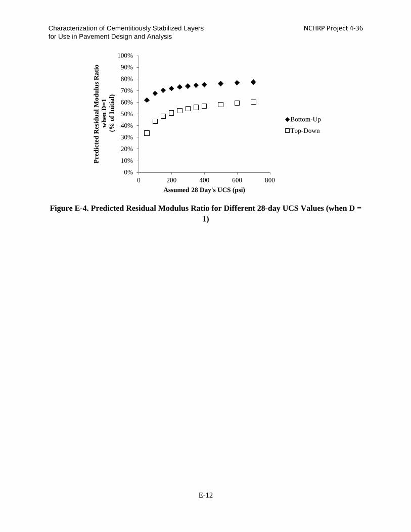
Characterization of Cementitiously Stabilized Layers NCHRP Project 4-36 for Use in Pavement Design and Analysis
Figure E-4. Predicted Residual Modulus Ratio for Different 28-day UCS Values (when D =
1)
0%
10%
20%
30%
40%
50%
60%
70%
80%
90%
100%
0 200 400 600 800
Pred
icte
d R
esid
ual M
odul
us R
atio
w
hen
D=1
(%
of I
nitia
l)
Assumed 28 Day's UCS (psi)
Bottom-Up
Top-Down
E-12

Characterization of Cementitiously Stabilized Layers NCHRP Project 4-36 for Use in Pavement Design and Analysis
CHAPTER E-3. SHRINKAGE CRACKING MODEL
Eqs. (E-8) and (E-9) present the shrinkage cracking models for crack spacing and crack width, respectively. Tables E-5 and E-6 present the model parameters, respectively.
𝑟𝑟𝑙𝑙𝑙𝑙 (𝐿𝐿
𝐻𝐻) = �� 𝜇𝜇
𝜌𝜌∙𝐻𝐻∙𝑐𝑐−2�𝑙𝑙1∙ (𝑐𝑐%)𝑙𝑙2 ∙ �𝜔𝜔
𝜌𝜌�𝑙𝑙3∙ (∆𝑇𝑇 ∙ 𝑈𝑈𝐶𝐶𝑇𝑇𝐸𝐸)𝑙𝑙4 ∙ � 𝑈𝑈𝑈𝑈𝑈𝑈28
𝜌𝜌∙𝐻𝐻2∙𝑐𝑐−2�𝑙𝑙5∙ (𝑅𝑅𝑅𝑅%)𝑙𝑙6 ∙ �𝜀𝜀𝑡𝑡𝑡𝑡𝑟𝑟
𝜀𝜀𝑟𝑟𝑢𝑢𝑡𝑡�𝑙𝑙7∙ �𝜀𝜀𝑡𝑡𝑡𝑡𝑟𝑟∙𝐸𝐸𝑡𝑡
𝑈𝑈𝐼𝐼𝐷𝐷𝐼𝐼�𝑙𝑙8� ∙ 𝑟𝑟9 Eq. (E-8)
𝑊𝑊 = �� 𝜇𝜇𝜌𝜌∙𝐻𝐻∙𝑐𝑐−2
�𝑤𝑤1∙ (𝑐𝑐%)𝑤𝑤2 ∙ �𝜔𝜔
𝜌𝜌�𝑤𝑤3∙ (∆𝑇𝑇 ∙ 𝑈𝑈𝐶𝐶𝑇𝑇𝐸𝐸)𝑤𝑤4 ∙ � 𝑈𝑈𝑈𝑈𝑈𝑈28
𝜌𝜌∙𝐻𝐻2∙𝑐𝑐−2�𝑤𝑤5∙ (𝑅𝑅𝑅𝑅%)𝑤𝑤6 ∙ �𝜀𝜀𝑡𝑡𝑡𝑡𝑟𝑟
𝜀𝜀𝑟𝑟𝑢𝑢𝑡𝑡�𝑤𝑤7∙ �𝜀𝜀𝑡𝑡𝑡𝑡𝑟𝑟∙𝐸𝐸𝑡𝑡
𝑈𝑈𝐼𝐼𝐷𝐷𝐼𝐼�𝑤𝑤8� ∙ 𝑤𝑤9 Eq. (E-9)
where
L = crack spacing, in. H = thickness of CSL, in. μ = coefficient of friction, psi/in. ρ = dry density, lb/ft3 t = age at time of crack survey, days c% = calcium content, % ω = water content, lb/ft3 ∆T = average daily maximum temperature variation, °F COTE = coefficient of thermal expansion, /°F UCS28 = 28-day UCS at 68°F and 100% RH RH = atmospheric relative humidity, % 𝜀𝜀𝑐𝑐𝑡𝑡𝑡𝑡 = shrinkage on top surface under daily environmental conditions 𝜀𝜀𝑐𝑐𝑙𝑙𝑐𝑐 = ultimate drying shrinkage SIDT = IDT strength, calculated from IDT strength growth model, psi Et = IDT modulus, calculated from IDT modulus growth model, psi li = regression parameters for crack spacing model, i = 0, 1, 2, 3, 4, 5, 6, 7 wi = regression parameters for crack width model, i = 0, 1, 2, 3, 4, 5, 6, 7.
Table E-5. Field-Calibrated Parameters of CSL Shrinkage Crack Spacing Model for Fine
and Coarse Host Materials Parameters Fine Materials Parameters Coarse Materials l1 (<0) -1.19E-01 l1 (<0) 0 l2 (>0) 5.98E-01 l2 (<0) -1.39E-01 l3 (<0) -7.78E-01 l3 (<0) -1.36E-04 l4 (<0) 0 l4 (<0) 0 l5 (>0) 0 l5 (<0) -1.46E-01 l6 (>0) 0 l6 (>0) 2.11E+00 l7 (<0) -2.20E-03 l7 (<0) 0 l8 (<0) -2.53E-01 l8 (<0) 0 l9 8.74E+00 l9 3.85E+00
( ) contains the parameter constraints.
E-13

Characterization of Cementitiously Stabilized Layers NCHRP Project 4-36 for Use in Pavement Design and Analysis
Table E-6. Field-Calibrated Parameters of CSL Shrinkage Crack Width Model for Fine and Coarse Host Materials
Parameters Fine Materials Parameters Coarse Materials w1 (>0) 7.81E-03 w1 (>0) 0 w2 (<0) -1.20E+00 w2 (>0) 0 w3 (>0) 7.67E-01 w3 (>0) 1.34E+00 w4 (>0) 0 w4 (>0) 1.76E-05 w5 (<0) 0 w5 (>0) 3.63E-02 w6 (<0) 0 w6 (<0) 0 w7 (>0) 6.69E-01 w7 (>0) 0 w8 (>0) 4.71E-01 w8 (>0) 5.36E-02 w9 8.63E-04 w9 1.78E-01
( ) contains the parameter constraints.
The shrinkage cracking models are appraised for three different materials (cement-clay, cement-silt and cement-gravel) and constant environmental conditions (68°F and 90% RH). The underlying layer under the CSL is clay with a coefficient of friction of 21.8 psi/in. Table E-7 presents the material properties.
Table E-7. Input for Simulation of Shrinkage Cracking Model
Cement-Clay Cement-Silt Cement-Gravel μ (psi/in.) 21.8 21.8 21.8
cement content (%) 12.0 8.0 3.0 c% 7.6 5.0 1.9
ω (lb/ft3) 18.6 13.3 8.7 γ (pcf) 103.2 119.9 140.1 H (in.) 4.0 4.0 4.0 UCS28 607.3 905.4 823.9
Ave Temp (°F) 68.0 68.0 68.0 ∆T (°F) 1.0 1.0 1.0 RH (%) 90.0 90.0 90.0
COTE (×10-6/°F) 12.6 9.3 8.5
Figures E-5 and E-6 present the appraisal results. The crack spacing and crack width are predicted for five years. The figures show that both crack spacing and crack width stabilize after two years. It is noted that in the field, reflective cracking could continue to develop in the asphalt layer after two years. The cement-silt has relatively large crack spacing compared to that of cement-clay and cement-gravel. Figure E-6 shows that the crack widths of the stabilized fine material are larger than those of the stabilized coarse material. Overall, the characteristics of the host materials directly affect the shrinkage behavior of the CSL, and the fine material exhibits more severe shrinkage crack distress than the coarse material.
E-14

Characterization of Cementitiously Stabilized Layers NCHRP Project 4-36 for Use in Pavement Design and Analysis
Figure E-5. Predicted Crack Spacing of Three Materials
Figure E-6. Predicted Crack Widths of Three Materials
1
10
100
1000
0 1 2 3 4 5
Cra
ck S
paci
ng (i
n.)
Age (Years)
Crack Spacing-Age
cement-clay
cement-silt
cement-gravel
0
0.01
0.02
0.03
0.04
0.05
0.06
0.07
0.08
0 1 2 3 4 5
Cra
ck W
idth
(in.
)
Age (Years)
Crack Width-Age
cement-clay
cement-silt
cement-gravel
E-15

Characterization of Cementitiously Stabilized Layers NCHRP Project 4-36 for Use in Pavement Design and Analysis
Appendix F. Bibliography
F-1

Characterization of Cementitiously Stabilized Layers NCHRP Project 4-36 for Use in Pavement Design and Analysis
Abadjieva T., "Chemical Stabilisation for Low Cost Roads in Botswana," First Road Transportation Technology Transfer Conference in Africa, 2001, pp. 364-369.
Abimbola A. F., Kehinde-Phillips O. O., and Olatunji A. S., “The Sagamu Cement Factory, SW Nigeria: Is the Dust Generated A Potential Health Hazard,” Environ Geochem Health, Vol. 29, 2007, pp. 163–167.
Abu-Bakr Megahed A. M., “Effect of Repeating Process of Shrinkage-Swelling on Behaviour of Improved Expansive Soils,” Twelfth European Conference on Soil Mechanics and Geotechnical Engineering, Jun 7-10, 1999, Amsterdam/Netherlands, pp. 1445-1450.
Abu-Zreig M. M., Al-Akhras N. M., and Attom M. F., “Influence of Heat Treatment on the Behavior of Clayey Soils,” Applied Clay Science, Vol. 20, 2001, pp. 129–135.
ACI, "Guide for Modeling and Calculating Shrinkage and Creep in Hardened Concrete," ACI 209.2R-08.
ACI, "State-of-the-Art Report on Soil Cement," ACI Materials Journal, Vol. 87, No. 4, July 1990, pp. 395-417.
Addison M. B. and Polma F. A., “Extending Durability of Lime Modified Clay Subgrades with Cement Stabilization,” Geo-Denver 2007: New Peaks in Geotechnics, 2007.
Aggarwal H. R. and Jafri R. H., "Modified Material Specifications for Base Laterites for Secondary Roads," Proceedings of the Regional Conference for Africa - Soil Mechanics and Foundation Engineering, Vol. 9, Issue 1, 1987, pp. 445-454.
AGPT 02 08, "Guide t oPavement Technology, Part 2-Pavement Structural Design."
Agrawal S.K., “FAA’s Pavement Research program,” May 26, 2004.
Ahnberg H., "Effects of Back Pressure and Strain Rate Used in Triaxial Testing of Stabilized Organic Soils and Clays," Geotechnical Testing Journal, Vol. 27, No. 3, May 2004, pp. 250-259.
Åhnberg H., “On Yield Stresses and the Influence of Curing Stresses on Stress Paths and Strength Measured in Triaxial Testing of Stabilized Soils,” Can. Geotech. J., Vol. 44, pp. 54–66.
Akhter M., hancock j., and hossain m., “A Study of Factors Affecting Roughness Progression on Portland Cement Concrete Pavements in Kansas,” Final Report To K-TRAN: KSU-99-4, Kansas State University, January 2004.
F-2

Characterization of Cementitiously Stabilized Layers NCHRP Project 4-36 for Use in Pavement Design and Analysis
Akhter M., Hossain M., Boyer J., and Parcells W.J., "Factors Affecting Rapid Roughness Progression on Portland Cement Concrete Pavements in Kansas," Transportation Research Record, No. 1809, 2002, pp. 74-84.
Akky M. R. and Shen C. K. “Erodibility of a Cement-Stabilized Sandy Soil,” Highway Research Board, Special Report No. 135, 1973, pp. 30-41.
Alam S.M., Little D.N., and Ledbetter W.B., "Evaluation of Fly Ash Test Sites Using a Simplified Elastic Theory Model and Field Measurements," Report to FHWA/TX-85/08+240-4F, Texas Transportation Institute, March 1984,
Al-Amoudi OSB., "Characterization and Chemical Stabilization of Al-Qurayyah Sabkha Soil," Journal of Materials in Civil Engineering, Vol. 14 No. 6, November 2002, pp. 478-484.
Alavi S., Tavares M. P., and Andress N. P., “Ride Specification Review for the Montana Department of Transportation,” Final Report to FHWA/MT-06-004/8179, Montana Department of Transportation, June 2006.
Alba J. L., "Laboratory Determination of Resilient Modulus of Granular Materials for Flexible Pavement Design," Ph.D. Dissertation, Georgia Institute of Technology, 1995.
Alderson A., “Guide to Pavement Technology--Part 4H-Test Methods,” Austroads, 2008.
Alexander M. L., "A Review of the Performance of Lime Treated Roadways in California," Final Report to CA-DOT-TL-332417514, California Department of Transportation, April 1976.
Alexander M. L., "Determination of Strength Equivalency Factors for the Design of Lime-Stabilized Roadways," Final Report to FHWA-CA-TL-78-37, California Department of Transportation, December 1978,
Alexander M., Ballim Y., and Santhanam M., "Performance Specifications for Concrete Using the Durability Index Approach," Indian Concrete Journal, Vol. 79, Issue 12, December 2005, pp. 41-46.
Alexander S., "Deflection, Shortening and Cracking Caused By Shrinkage in Reinforced Sections, In-Situ Toppings and Composite Slabs," Role of Cement Science in Sustainable Development - Proceedings of the International Symposium - Celebrating Concrete: People and Practice, 2003, pp. 431-440.
Ali G. A. and Youssef A-FA, "Stabilization of Silt: A Case Study for Low-Volume Roads in Saudi Arabia," Transportation Research Record, No. 898, 1983, pp. 283-290.
F-3

Characterization of Cementitiously Stabilized Layers NCHRP Project 4-36 for Use in Pavement Design and Analysis
Ali G. A., "Evaluation of Stabilized Bases, Double Sand Seal, and Slurry Seal Pavement Sections in the Sultanate of Oman," Developments in Arid Regions Research Series, Issue 1, 2000, pp. 165-173
Ali-Khodja H., Belaala A., Demmane-Debbih W., Habbas B., and Boumagoura N., “Air Quality and Deposition of Trace Elements in Didouche Mourad, Algeria,” Environ Monit Assess, Vol. 138, 2008, pp. 219–231.
Al-Kuaja W. A., “Engineering Properties and Durability of Conventional and High-Strength Concretes Used in Bahrain,” Housing Science, Vol. 22, No., 1, 1998, pp. 137-146.
Allen J. J., Currin D. D., and Little D. N., "Mix Design, Durability, and Strength Requirements for Lime-Stabilized Layers in Airfield Pavements," Transportation Research Record, No. 641, 1977, pp. 34-41.
Al-Manaseer A. and Ristanovic S., “Sensitivity of the Models for Predicting Shrinkage of Concrete,” American Concrete Institute, Vol. 227, 2005, pp. 41-65.
Al-manasseer A., “Predicting Drying Shrinkage of Concrete,” Concrete International, Vol. 26, Issue 8, 2004, pp. 79-83.
Al-Qadi I. L., Elseifi M., and Carpenter S. H., “Reclaimed Asphalt Pavement – A Literature Review,” Research Report FHWA-ICT-07-001, Illinois Department of Transportation, March 2007.
Al-Rawas A. A., Taha R., Nelson J.D., Al-Shab T.B., and Al-Siyabi H., “A Comparative Evaluation of Various Additives Used in the Stabilization of Expansive Soils,” Geotechnical Testing Journal, Vol. 25, Issue 2, June 2002.
Al-Rawas A. L., Hago A. W., and Al-Sarmi H., “Effect of Lime, Cement and Sarooj (Artificial Pozzolan) on the Swelling Potential of an Expansive Soil from Oman,” Building and Environment, Vol. 40, 2005, pp. 681–687.
Al-Shayea N. A, “The Combined Effect of Clay and Moisture Content on the Behavior of Remolded Unsaturated Soils,” Engineering Geology, Vol. 62, 2001, pp. 319-342.
American Association of State Highway and Transportation Officials, "Guidelines and Guide Specifications for Using Pozzolanic Stabilized Mixture (Base Course or Subbase) and Fly Ash for In-Place Subgrade Soil Modification," Task Force 28 Report, August 1990,
American Concrete Institute, "State-of-the-Art Report on Soil Cement," Report to ACI 230.1R-90, May 1991,
Anagnos J. N. and Kennedy T. W., “Practical Method of Conducting the Indirect Tensile Test,” Research Report No. 98-10, The Texas Highway Department, August 1972.
F-4

Characterization of Cementitiously Stabilized Layers NCHRP Project 4-36 for Use in Pavement Design and Analysis
Anagnos J. N., Kennedy T. W., and Hudson W. R., “Evaluation and Prediction of Tensile Properties of Cement-Treated Materials,” Research Report No. 98-8, The Texas Highway Department, October 1970.
Anastácio A. S., Aouad A., Sellin P., Fabris J. D., Bergaya F., and Stucki J. W., “Characterization of a Redox-Modified Clay Mineral with Respect to Its Suitability as a Barrier in Radioactive Waste Confinement,” Applied Clay Science, Vol. 39, 2008, pp. 172–179.
Anday M. C., "Curing Lime Stabilized Soils," Highway Research Record, No 29, 1963, pp. 13-26.
Anderson K. W., Uhlmeyer J., and Pierce L., “Performance of a Portland Cement Concrete Pavement with Longitudinal Tined, Transverse Tined, and Carpet Drag Finish,” Post Construction Report, No. WA-RD 666.1, Washington State Department of Transportation, April 2007.
Anderson K.W., Uhlmeyer J., Pierce L., and Weston J., “Wear Resistant Pavement Study, ” Experimental Feature Report, October 2006.
Andrew C. Palmer, 2007, Dimensional Analysis and Intelligent Experimentation, World Scientific Publishing Co. Pte. Ltd, Singapore
Andrews R.C., "Rational Pavement Material Investments," Proceedings - Conference of the Australian Road Research Board, 1998, 155-177.
Andry H., Yamamoto T., and Inoue M., "Effectiveness of Hydrated Lime and Artificial Zeolite Amendments and Sedum (Sedum Sediforme) Plant Cover in Controlling Soil Erosion from an Acid Soil," Australian Journal of Soil Research, Vol. 45, Issue 4, 2007, pp. 266-279.
Anon, "Volume Change in Concrete," Indian Concrete Journal, Vol. 60, Issue 5, May, 1986, pp. 113-114.
António G. F. de Sousa Coutinho, “Data Reduction of Horizontal Load Full-Scale Tests on Bored Concrete Piles and Pile Groups,” Journal of Geotechnical and Geoenvironmental Engineering, June 2006, pp. 752-769.
Anttikoshi U., "Stabilized Clay as Earth Construction Material," International Conference on Practical Applications in Environmental Geotechnology; Ecogeo 2000, Helsinki, Finland, September 4-6, 2000, pp. 11-18.
Appea A.K., and Al-Qadi I.L., "Assessment of Falling Weight Deflectometer Data for Stabilized Flexible Pavements," Transportation Research Record, No. 1709, 2000, pp. 19-25.
F-5

Characterization of Cementitiously Stabilized Layers NCHRP Project 4-36 for Use in Pavement Design and Analysis
Applied Research Associates, INC., "Guide for Mechanistic-Empirical Design for New and Rehabilitated Pavement Structures" NCHRP 1-37A Final Report, Prepared for National Cooperative Highway Research Program, Thansportation Research Board, National Research Council, March 2004.
Arbogast A. F., “Estimating the Time since Final Stabilization of a Perched Dune Field Along Lake Superior,” Professional Geographer, Vol. 52(4), 2000, pp. 594-606.
Ardani A., "Expansive Soil Treatment Methods in Colorado," Final Report to CDOT-DTD-R-92-2, Colorado Department of Transportation, March 1992.
Ardani A., Suthahar N., and Morian D.A., “Early Evaluation of Ltpp Specific Pavement Studies-2, Colorado,” Interim Report, No. CDOT-DTD-R-2000-2. Colorado Department of Transportation, March 2000.
Armaghani J. M., "Testing of Concrete Permeability for Durability Evaluation," Structural Engineering in Natural Hazards Mitigation, 1993, pp. 989-995.
Arman A. and Munfakh G. A., "Stabilization of Organic Soils with Lime," Louisiana State Univ & Agr & Mech Coll, Bull No. 103, 1970.
Arman A. and Munfakh G. A., “Stabilization of Organic Soils with Lime,” Highway Research Board, Vol. 381, 1972, pp. 37-45.
Arora M. G., Khanna S. K., and Vasan R. M., “Durability and Strength Characteristics of Lime-Flyash - Soil Mixtures for Road Construction,” Road Research Bulletin, Vol. 14, 1971, pp. 55-71.
Arora P. L., Crowther L., and Akhter G., "Soil Stabilization for Low-Volume Roads, Volume 1, Executive Summary, Phase II," Final Report to FHWA/RD-86/096, Sheladia Associates, Incorporated, May 1986.
Arora P. L., Crowther L., and Akhter G., "Soil Stabilization for Low-Volume Roads, Volume 2 - Road Engineer's Guide, Phase II," Final Report to FHWA/RD-86/097, Sheladia Associates, Incorporated, May 1986.
Arora P. L., Crowther L., and Akhter G., "Soil Stabilization for Low-Volume Roads, Volume 3 - Road Builder's Guide, Phase II," Final Report to FHWA/RD-86/098, Sheladia Associates, Incorporated, May 1986.
Arora P. L., Crowther L., and Akhter G., "Soil Stabilization for Low-Volume Roads, Volume 4 - Cost-Benefit Analysis, Phase II," Final Report to FHWA/RD-86/099, Sheladia Associates, Incorporated, May 1986.
Arora S. and Aydilek A. H., "Class F Fly-Ash-Amended Soils as Highway Base Material," Journal of Materials in Civil Engineering, Vol. 17, No. 6, November 2005, pp. 640-649.
F-6

Characterization of Cementitiously Stabilized Layers NCHRP Project 4-36 for Use in Pavement Design and Analysis
Arrieiro de Oliveira P.C., Sant'Anna F.M.G., and Vasconcellos de Souza F.S., "Pavement Rehabilitation through Recycling with the Addition of Portland Cement on Highway SP-351," 2005 International Symposium on Pavement Recycling, 2005.
ASCE, "Pavement Mechanics and Performance: Proceedings of Sessions of GeoShanghai, June 6-8, 2006, Shanghai."
Ashmawy A., McDonald R., Carreon D., and Atalay F., "Stabilization of Marginal Soils Using Recycled Materials," Final Reprot to BD-544-4, Florida Department of Transportation, February 19, 2006.
Ashtiani R. S., Little D.N., Masad E., “Evaluation of the Impact of Fines on the Performance of Lightly Cement-Stabilized Aggregate Systems,” Journal of the Transportation Research Board, No. 2026, 2007, pp. 81–88.
Asi I.M., Qasrawi H. Y., and Shalabi F. I., “Use of Steel Slag Aggregate in Asphalt Concrete Mixes, ”Can. J. Civ. Eng., Vol.34, 2007, pp.902–911.
Assaad Abdelmseeh V., Jofriet J., and Hayward G., “Sulphate and Sulphide Corrosion in Livestock Buildings, Part I-Concrete deterioration,” Biosystems Engineering, Vol. 99, 2008, pp. 372 – 381.
ASTM D 1502-04, “Standard Test Method for Unconfined Compressive Strength of Compacted Soil-Lime Mixtures”, American Society for Testing and Materials.
Atkinson D.J., "Evaluation of Rehabilitation Measures for Cracked Cement Treated Pavements," Main Road Department, Queensland, Australia, Vol. 6, 1990.
Attiogbe E. K., “Predicting Freeze-Thaw Durability of Concrete—A New Approach,” ACI Materials Journal, September-October 1996, pp. 1-8.
Attom M. F., “Shear Strength Characteristics of Irbid Clayey Soil Mixed with Iron Filling and Iron Filling–Cement Mixture,” Environ Geol, Vol. 55, 2008, pp. 781–788.
Aufmuth R. E., "Stabilization of Inorganic Silts: Panamanian Soils," Technical Report M-15, Construction Engineering Research Laboratory, April 1972.
Aufmuth R. E., "Stabilization Studies of Southeast Asian Soils: Vietnam," Tech Rept M-17, Construction Engineering Research Laboratory, June 1972.
Aufmuth R. E., "Stabilization Studies: Turkish Soils," Technical REPORT M-8, Construction Engineering Research Laboratory, July 1971.
Austroads Inc., “Austroads Technical Report--Austroads Test Methods--Summary for 2005-06 (Ap-T48),” 2006.
Austroads Inc., “Austroads Technical Report--Case Study and Test Method Review on Moisture Damage (AP-T76-07),” 2007.
F-7

Characterization of Cementitiously Stabilized Layers NCHRP Project 4-36 for Use in Pavement Design and Analysis
Austroads, "Flexural Beam Test Method--Modulus and Fatigue," Austroads 2008, pp. 55-59.
Austroads, "Guide to Pavement Technology: Part 2: Pavement Structural Design," 2008.
Austroads, "Guide to Pavement Technology: Part 4D: Stabilised Materials," 2006.
Austroads, "Guide to Pavement Technology: Part 4L: Stabilising Binders," 2009.
AustStab, "AustStab Technical Note-Lime stabilisation practice," No. 1E, June 2008.
AustStab, "Lime Stabilisation Practice," AustStab Technical Note, No.1E, June 2008.
Avery L. M., Williams A. P., Killham K., and Jones D. L., “Heat and Lime-Treatment as Effective Control Methods for E. Coli O157--H7 In Organic Wastes,” Bioresource Technology, Vol. 100, 2009, pp. 2692–2698.
Aydilek A. H. and Arora S., "Fly Ash Amended Soils as Highway Base Materials," Geotechnical Engineering for Transportation Projects, Geo-Trans, 2004,
Aytekin M., "Soil Stabilization with Lime and Cement," Insaat Muhendisleri Odasi Teknik Bulten, Vol. 9, December, 1998, pp. 471-477.
Azam S., “Compressibility and Swelling Characteristics of Al-Khobar Palygorskite, Eastern Saudi Arabia; Discussion,” Engineering Geology, Vol.92, 2007, pp. 170–172.
Azam S. and Abduljauwad S. N., “Influence of Gypsification on Engineering Behavior of Expansive Clay,” Journal of Geotechnical and Geoenvironmental Engineering, Vol. 126, No. 6, June, 2000, pp. 538-542.
Azam S., “Study on the Swelling Behaviour of Blended Clay-Sand Soils,” Geotech Geol Eng, Vol. 25, 2007, pp. 369–381.
Babic B., "Relationships between Mechanical Properties of Cement Stabilized Materials," Materials and Structures/Materiaux et Constructions, Vol. 20, Issue 120, November 1980.
Badeev S. Y., Kuznetsov M. V. and Isaev V. B.,” Use OF Disturbed Samples for Quality Control of Soil Cement,” Soil Mechanics and Foundation Engineering, Vol. 45, No. 6, 2008, pp.202-205.
Bagenal H. E., “Exposure, Durability and Maintenance in Modern Design,” The AA Journal, 1952, pp. 183-194.
Bagenal H., "Exposure, Durability and Maintenance in Modern Design," Architect and Building News, Vol. 201, February 1952, pp. 205-208.
Bahrekazemi M., "Effects of Lime-Cement Soil Stabilization against Train Induced Ground Vibrations," Geotechnical Special Publication, Vol. 1201, 2003, pp. 562-574.
F-8

Characterization of Cementitiously Stabilized Layers NCHRP Project 4-36 for Use in Pavement Design and Analysis
Baldocchi R. v., "Recycling Concrete and Asphalt Pavements Rehabilitation of Runway 18R-36L Orlando International Airport," Airport Pavement Innovations Theory to Practice, 1993, pp. 266-274.
Ballantine R. W. and Rossouw A. J., "Lime Stabilization of Soils," Northern Lime Co, Ltd /S Africa, September 1972.
Balzamo S., "Experimental and Theoretical Studies for Assessing the Retention Capacity of Cement Stabilized Materials for Land Disposal," ASTM Special Technical Publication, Vol. 1240, 1996, pp. 388-412.
Barbu B., "Identification and Stabilization of Problematic Silts," Ph.D. Dissertation, University of New Orleans, 2004
Barde A., Parameswaran S., Chariton T., Weiss J., Newbolds S., “Evaluation of Rapid Setting Cement-Based Materials for Patching and Repair,” Final Report to FHWA/IN/JTRP/2006-11, Purdue University, October 2006.
Bardon T. L., Rose A. T., and Duncan J. M., “Drained and Undrained Strength Interpretation for Low-Plasticity Silts,” Journal of Geotechnical and Geoenvironmental Engineering, Vol. 132, No. 2, February 1, 2006, 250–257.
Barenberg E. J. and Thompson M. R., "Design, Construction, and Performance of Lime, Fly Ash, and Slag Pavement," Transportation Research Record, No. 839, 1982, pp. 1-6.
Barksdale R. D. and Vergnolle R. R., “Expansive Cement Stabilization of Bases,” Highway Research Record, Issue 255, 1968, pp. 30-41.
Barnes C., “Structural Evaluation of the Point Michaud Road Pavement Rehabilitation Using Full-Depth Reclamation with Portland Cement,” April 7, 2008.
Barr B., Hoseinian S. B., Beygi M. A., “Shrinkage of Concrete Stored in Natural Environments,” Cement & Concrete Composites, Vol. 25, 2003, pp. 19–29.
Barra M., Ramonich E. V., and Munoz M. A., "Stabilization of Soils with Steel Slag and Cement for Application in Rural and Low Traffic Roads," Beneficial Use of Recycled Materials in Transportation Applications, 2001, pp. 423-432.
Barre P. AND HALLETT P. D., “Rheological Stabilization of Wet Soils by Model Root and Fungal Exudates Depends on Clay Mineralogy,” European Journal of Soil Science, Vol. 60, Issue 4, 2009, pp. 525-538.
Barstis W. F. and Crawley A. B., “The Use of Fly Ash in Highway Construction U.S. 84/98 Adams County,” Final Report to 84-DP59-MS-05, Federal Highway Administration, May 2000.
F-9

Characterization of Cementitiously Stabilized Layers NCHRP Project 4-36 for Use in Pavement Design and Analysis
Barstis W. F., "Long-Term Effect of Lime-Fly Ash Treated Soils," Final Report to FHWA/MS-DOT-RD-03-147, Mississippi Department of Transportation, December 2003.
Barstis W.F. and Metcalf J., "A Practical Approach to Criteria for the Use of Lime-Fly Ash Stabilization in Base Courses," Journal of the Transportation Research Board, No. 1936, 2005, pp. 20–27.
Bartlett S. and Farnsworth C., “Performance of Lime Cement Stabilized Soils for the I-15 Reconstruction Project, Salt Lake,” TRB ID Number: 02-3314, 2002.
Basheer L., Basheer P. A. M., and Long A. E., "Influence of Coarse Aggregate on the Permeation, Durability and the Microstructure Characteristics of Ordinary Portland cement Concrete," Construction and Building Materials, Vol. 19, Issue 9, 2005, pp. 682-690.
Basma A.A. and Tuncer E.R., "Effect of Lime on Volume Change and Compressibility of Expansive Clays," Transportation Research Record, No. 1295, 1991, pp. 52-61.
Bass R. P., "Quality Control of Soil-Cement Construction for Water Resources," Geotechnical Special Publication, Issue 95, 2000, pp. 13-25.
Basu R. and Arulanandan K., “A New Approach for the Identification of Swell Potential of Soils,” Proceedings of Workshop on Expansive Clays and Shales in Highway Design and Construction, Denver, Colorado, December 1972, pp. 315-339.
Batchelor B., “Overview of Waste Stabilization with Cement,” Waste Management, Vol. 26, 2006, pp. 689–698.
Bausano J. and Williams R. C., “Transitioning from AASHTO T283 to the Simple Performance Test Using Moisture Conditioning,” Journal of Materials in Civil Engineering, Vol. 21, No. 2, February 1, 2009, pp. 73-82.
Baveye P., “Operational Aspects of the Mechanics of Deforming Porous Media: Theory and Application to Expansive Soils,” Mechanics of Swelling: From Clays to Living Cells and Tissues, Vol. 64, 1992, pp. 79-96.
Bazant Z. P. and Baweja S., “Creep and Shrinkage Prediction Model for Analysis and Design of Concrete Structures - Model B3,” Materials and Structures, Vol. 28, Issue 180, 1995, pp. 357-365.
Bazant Z. P. and Chern J., “Stress-Induced Thermal and Shrinkage Strains in Concrete,” Journal of Engineering Mechanics, Vol. 113, No. 10, October, 1987, pp. 1493-1511.
Bazant Z. P., “Creep and Shrinkage Prediction Model for Analysis and Design of Concrete Structures: Model B3 - Short Form,” Adam Neville Symposium: Creep and Shrinkage - Structural Design Effects, 2000, pp. 85-100.
F-10
Characterization of Cementitiously Stabilized Layers NCHRP Project 4-36 for Use in Pavement Design and Analysis
Bazant Z. P., “Creep and Shrinkage Prediction Model for Analysis and Design of Concrete Structures: Model B3,” Adam Neville Symposium: Creep and Shrinkage - Structural Design Effects, 2000, pp. 1-83.
Bazant Z. P., Chern J., Rosenberg A. M., and Gaidis J. M., “Mathematical Model for Freeze-Thaw Durability of Concrete,” Journal of the American Ceramic Society, Vol. 71, No. 9, September 1988, pp. 776-783.
Beaudry T. M., "Minnesota's Design Guide for Low Volume Aggregate Surfaced Roads," Final Report to MN/RD-92/11, Minnesota Department of Transportation, July 1992.
Beckham T. and Hopkins T., "Swelling Pavement_ KY 499 Estill County," Research Report to KTC-05-01/SPR 270-03-1I, Kentucky Transportation Center, March 2005.
Beeghly J. H., “Recent Experiences with Lime-Fly Ash Stabilization of Pavement Subgrade Soils, Base, and Recycled Asphalt,” 2003 International Ash Utilization Symposium, 2003.
Benboudjema F., Meftah F., and Torrenti J., “Structural Effects of Drying Shrinkage,” Journal of Engineering Mechanics, Vol. 131, No. 11, November 1, 2005, pp. 1195-1199.
Benedetti M., Fontanari V., Scardi P., Ricardo C. L. A., and Bandini M., “Reverse Bending Fatigue of Shot Peened 7075-T651 Aluminium Alloy-The Role of Residual Stress Relaxtion,” International Journal of Fatigue, Vol. 31, 2009, pp. 1225–1236.
Benkelman A. C., Kingham R.I., and Schmitt H. M., “Performance of Treated and Untreated Aggregate Bases,” Highway Research Board, Vol. 73, 1982, pp. 242-255.
Bennethum L. S., Murad M., and Cushman J. H., “Macroscale Thermodynamics and the Chemical Potential for Swelling Porous Media,” Transport in Porous Media, Vol. 39, 2000, pp. 187–225.
Benson, C. H., Edil, T. B., Ebrahimi, A., Kootstra, R. B., Li, L., and Bloom, P., "Use of Fly Ash for Reconstruction of Bituminous Roads: Large Scale Model Experiments," Minnesota Department of Transportation, St Paul, MN, 2009. (http://www.recycledmaterials.org/ Research/current/ project_47/project_47_final_report.pdf)
Bentz D. P., Clifton J. R., Ferraris C. F., and Garboczi E. J., “Transport Properties and Durability of Concrete--Literature Review and Research Plan,” NISTIR 6395, September 1999.
Bergeson K. L., Pitt J. M., and Demirel T., "Increasing Cementitious Products of a Class C Fly Ash," Transportation Research Record, No. 998, 1984, pp. 41-46.
F-11

Characterization of Cementitiously Stabilized Layers NCHRP Project 4-36 for Use in Pavement Design and Analysis
Berthelot C.F., Marjerison B., Houston G., McCaig J.D., Warrener S., and Gorlick R. "Mechanistic Comparison of Cement- and Bituminous-Stabilized Granular Base Systems," Journal of the Transportation Research Board, No. 2026, 2007, pp. 70-80.
Berthelot, Podborochynski D., Marjerison B. L., Haichert E.I.T. R., and Gerbrandt R. R., "Triaxial Frequency Sweep Characterization of Saskatchewan Granular Base Across Increasing Fines Content and Stabilization Systems," Transportation Research Board 88th Annual Meeting, 2009.
Berthelot, Stuber E., Podborochynski D., Marjerison B. L., Gerbrandt R. R., and Warrener S."Seasonal Effects on Structural Performance of Alternative Road-Strengthening Systems in Saskatchewan, Canada," Transportation Research Board 88th Annual Meeting, 2009.
Bertholot C. and Gerbrandt R., “Cold In-Place Recycling and Full Depth Strengthening of Expansive Subgrade Soils using Cementitious Waste Products in Northern Climates,” TRB 2002 Annual Meeting CD-ROM, 2002.
Better Roads, "A Look at Soil Stabilization and Drainage," Vol. 58, Issue 3, March 1988, pp. 32-34.
Beushausen H. and Alexander M. G., “Failure Mechanisms and Tensile Relaxation of Bonded Concrete Overlays Subjected to Differential Shrinkage,” Cement and Concrete Research, Vol. 36, 2006, pp. 1908-1914.
Bhattacharja S. and Bhatty J., “Comparative Performance of Portland Cement and Lime Stabilization of Moderate to High Plasticity Clay Soils,” RD125, Portland Cement Association, Skokie, Illinois, USA, 26 pages, 2003.
Bhattacharya P. G. and Pandey B. B., “Study of Strength and Curing of Lime-Stabilised Laterite Soil - Plain And Fiber-Reinforced,” Highway Research Bulletin, Vol. 24, 1984, pp. 1-26.
Bhattacharya P. G., "Flexural Fatigue Strength of Lime-Laterite Soils at Different Densities and Thickness Design Procedure for Lime-Laterite Pavement Base," Highway Research Bulletin, Vol. 29, 1986, pp. 1-18.
Bhatti M.A., Barlow J.A., Stoner J.W., “Modeling Damage to Rigid Pavements Caused by Subgrade Pumping,” Journal of Transportation Engineering, January/February 1996, pp. 12-21.
Bischoff D., “Investigative Study of the Italgrip™ System,” Final Report to WI-04-08, Wisconsin Department of Transportation, September 2008.
Bissala Y. Y. and Payne W., “Effect of Pit Floor Material on Compost Quality in Semiarid West Africa,” Soil Sci. Soc. Am. J., Vol. 70, 2006, pp. 1140–1144.
F-12

Characterization of Cementitiously Stabilized Layers NCHRP Project 4-36 for Use in Pavement Design and Analysis
Bittner J. D. and Gasiorowski S. A., “STI's Six Years of Commercial Experience in Electrostatic Benefication of Fly Ash,” 2001 International Ash Utilization Symposium, 2001.
Bjegovic D., Krstic V., Mikulic D., and Ukrainczyk V., “C-D-c-t Diagrams for Practical Design of Concrete Durability Parameters,” Cement and Concrete Research, Vol. 25, No. 1, 1995, pp. 187-196.
Blanchon P. and Jones B., “Marine-Planation Terraces on the Shelf around Grand Cayman; a Result of Stepped Holocene Sea-Level Rise,” Journal of Coastal Research, Vol. 11, No. 1, Winter, 1995, pp. 1-33.
Boardman D. L., Glendinning S., and Pogers C. D. F., “Development of Stabilisation and Solidification in Lime–Clay Mixes,” Geotechnique, Vol. 50, No. 6, 2001, pp. 533-543.
Boardman D.I., Glendinning S., Rogers CDF, Holt C.C., "In Situ Monitoring of Lime-Stabilized Road Subgrade," Transportation Research Record, No. 1757, 2001, pp. 3-13.
Bofinger H. E., “Soil-Cement--Recent Research by the Overseas Unit of TRRL,” ARRB Proceedings, Vol. 9, Part 4, 1978, pp. 49-53.
Bofinger H. E., “The Behaviour of Soil-Cement Pavements with Special Reference to the Problem of Cracking,” Fourth Asian Regional Conference on Soil Mechanics and Foundation Engineering, July 1971, Bangkok, Thailand, pp. 355-360.
Bofinger H. E., “The Structure of Soil-Cement,” Australian Road Research, Vol. 2, Issue 1, 1984, pp. 46-51.
Bofinger H. E., Hassan H. O., and Williams R. I. T., “The Shrinkage of Fine-Grained Soil-Cement,” TRRL Supplementary Report 398, 1978.
Boles W.F., "Fly Ash Soil Stabilization Figures in FHWA Research," Roads & Bridges, Vol. 25, No. 5, May 1987, pp. 80-81.
Bonnot J., "Semi-rigid Pavements," Association internationale permanente des congrès de la route, 1991.
Boswell W. F., "Soil Stabilization/Soil Cement Mark-Lang, Inc.'S Approach," Soil-Cement and Other Construction Practices in Geotechnical Engineering. Proceedings of Sessions of Geo-Denver 2000, 2000, pp. 26-35.
Botha p. B., Semmelink C. J., and Raubenheimer J., “Problems Experiences with the Construction of Cement and Lime Stabilized Layers and Working Solutions for These Problems.”
Botha P. B., Semmelink C. J., and Raubenheimer J., “The Real Cause of Detrimental Carbonation in Chemically Stabilized Layers and Possible Solutions.”
F-13
Characterization of Cementitiously Stabilized Layers NCHRP Project 4-36 for Use in Pavement Design and Analysis
Botha P.B., Semmelink C.J., Raubenheimer J., Perry B., and Hodgkinson A., “Investigation into the Early Trafficking of Emulsion Treated (ETB), Foamed Bitumen (FB) Bases Treated in Combination with Cement and Cement (OPC) only.”
Bouazza A., Kwan P. S., and Chapman G., "Strength Properties of Cement Treated Coode Island Silt by the Soil Mixing Method," Geotechnical Engineering for Transportation Projects, Geo-Trans 2004, 2004.
Bowser J. D., Krause G. L., and Tadros M. K., "Freeze-Thaw Durability of High-Performance Concrete Masonry Units," ACI Materials Journal, Vol. 93, Issue 4, July-August, 1996, pp. 386-394.
Boyd A. J. and Hooton R. D., “Long-Term Scaling Performance of Concretes Containing Supplementary Cementing Materials,” Journal of Materials in Civil Engineering, Vol. 19, No. 10, October 1, 2007, pp. 820–825.
Bradford M. A. and Wright H. D., “Time-Dependent Local Buckling in Thin-Walled Lightweight Composites,” J. Construct. Steel Res., Vol. 46, Nos. 1-3, 1998, pp. 221.
Brandl H., "Mixed-in-Place Stabilisation of Pavement Structures with Cement and Additives," Proceedings of the ... European Conference on Soil Mechanics and Geotechnical Engineering = Comptes Rendus du ... Congres Europeen de Mecanique des Sols et de la Geotechnique, Vol. 1936, Issue 3, 1999, pp. 1473-1481.
Brandl H., “Mixed-In-Place Stabilization of Pavement Structures with Cement and Additives,” Twelfth European Conference on Soil Mechanics and Geotechnical Engineering (Proceedings), 1999, pp. 1473-1481.
Brandon T. L., Filz G. M., and Geiman C. M., "Stabilization of Soft Clay Subgrades in Virginia: Phase I Laboratory Study," Final Contract Report to VTRC 05-CR16, Virginia Transportation Research Council, May 2005.
Brar H. S., Tutumluer E., Thompson M. R., Gosain L., and Anderson R., “Charaterizing Subgrade Soils and Establishment Treatment Needs for a New Runway at the Chicago's Ohare Areport,” Airfield and Highway Pavements, 2006, pp. 272-283.
Bredenkamp S. and Lytton R.L., “Reduction of Sulfate Swell in Expansive Clay Subgrades in the Dallas District,” Report No. TX-95/1994-5, Texas Department of Transporation, 1995.
Bredenkamp S. and Scullion T., "Forensic Evaluation of the Cement Treated Base Failure on SH 36 in Houston," Research Report to TX-96/2919-2, Texas Department of Transporation, 1995.
Brow R. K., “Alkali-Resistant Calcium Iron Phosphate Glass Fibers for Concrete Reinforcement,” Final Report to UTC R129, U.S. Department of Transportation, February 2008.
F-14

Characterization of Cementitiously Stabilized Layers NCHRP Project 4-36 for Use in Pavement Design and Analysis
Brown S. F., “Design of Pavements with Lean-Concrete Bases,” Transportation Research Record, Vol. 725, 1979, pp. 51-58.
Bryan A. J., "Criteria for the Suitability of Soil for Cement Stabilization," Building and Environment, Vol 23, Issue 4, 1988, pp. 309-319.
Bubshait A. A., “Quality of pavement construction in Saudi Arabia,” Practice Periodical on Structural Design and Construction, Vol. 6, No. 3, August, 2001, pp. 129-136.
Buerger W., "Lime Used in Soil Stabilization," Report to CRREL-TL-564, Cold Regions Research and Engineering Laboratory, December 1976.
Bullman J. N., "Soil Stabilization in Africa," Department of the Environment, England, 1972.
Burn S. and Tillman K. A., "Evaluation of the Strength of Cement-Treated Aggregate for Pavement Bases," Final Contract Report to VTRC 06-CR7, Virginia Department of Transportation, April 2006.
Burroughs S., “Soil Property Criteria for Rammed Earth Stabilization,” Journal of Materials in Civil Engineering, Vol. 20, No. 3, March 1, 2008, pp. 264-273.
Burt III W.T. and Melancon J., “Soil-Cement Design Study,” Research Project No. 68-9S Louisiana HPR 1 (9), 1971.
Busch C., Henrichsen A., and Thorgersen F., "Establishing a Mechanistic Incremental Design Method for Semi-Rigid Pavements through HVS Testing," Pavement Mechanics and Performance - GeoShanghai International Conference, 2006, pp. 117-125.
Busch C., Thøgersen F., and Henrichsen A., “Development and Validation of a Mechanistic Recursive-Incremental Deterioration Model for Cement-Stabilized Base Courses,” TRB 2006 Annual Meeting CD-ROM, 2006.
Bushman W. H., Freeman T. E., and Hoppe E. J., "Stabilization Techniques for Unpaved Roads," Journal of the Transportation Research Board, No. 1936, 2005, pp. 28-33.
Button J. W., Estakhri C., and Wimsatt A., “A Synthesis of Warm-Mix Asphalt,” Technical Report to SWUTC/07/0-5597-1, Southwest Region University Transportation Center, April 2007.
Buyukozturk O. and Ameur-moussa R., "A Bounding Surface Model for Concrete," Bulletin of the Technical University of Istanbul, Vol. 41 Issue 2, 1988, pp. 169-199.
Cai Z., Jensen D., and Bager D. H., “Re-Use of Stabilised Flue Gas Ashes from Solid Waste Incineration In Cement-Treated Base Layers for Pavements,” Waste Manage Res, Vol. 21, 2003, pp. 42–53.
F-15

Characterization of Cementitiously Stabilized Layers NCHRP Project 4-36 for Use in Pavement Design and Analysis
Camargo F. F., Edil T. B., and Benson C. H., “Strength and Stiffness of Recycled Base Materials Blended with Fly Ash,” TRB 2009 Annual Meeting CD-ROM, 2009.
Cara S., Carcangiu G., Padalino G., Palomba M., and Tamanini M., “The Bentonites in Pelotherapy--Chemical, Mineralogical and Technological Properties of Materials from Sardinia Deposits (Italy),” Applied Clay Science, Vol. 16, 2000, pp. 117-124.
Carpenter S. H., Crovetti M. R., Smith K. L., Rmeili E., and Wilson T., "Soil and Base Stabilization and Associated Drainage Considerations. Volume I: Pavement Design and Construction Considerations," Final Report to FHWA-SA-93-004, ERES Consultants, Incorporate, December 1992.
Carpenter S. H., Crovetti M. R., Smith K. L., Rmeili E., and Wilson T., "Soil and Base Stabilization and Associated Drainage Considerations. Volume II: Mixture Design Considerations," Final Report to FHWA-SA-93-005, ERES Consultants, Incorporate, December 1992.
Carter O.K. "Shrinking Soil is Cracking Them Up On The East Side," Fort Worth Star-Telegram, Texas, Vol. 1, Issue 1, August 20, 2006.
Carteret R. D., Chen H., Comport L., Firth D., and Howard A., “Cost-effective Structural Treatments for Rural Highways--Cemented Materials,” Interim Report, Austroads Project No: TT1359, June 2009.
Casagrande T., Misano V., Pagano C. H., and Sferra F., "Soil-Binding Agent Affinity in Soil Stabilisation with Cement and/or Lime," Twelfth European Conference on Soil Mechanics and Geotechnical Engineering (Proceedings), 1999, pp. 1749-1754.
Castel A. K. and Arulanandan K., "New Approach to Predict Lime Reactivity of Soils," ASCE Journal of the Geotechnical Engineering Div, Vol. 105, No. GT4, April 1979, pp. 563-568.
Catalan L. J. J., Buset K. C., and Yin G., “Reactivity of Oxidized Sulfidic Mine Tailings during Lime Treatment,” Environ. Sci. Technol., Vol. 36, 2002, pp. 2766-2771.
Catton M. D., "Basic Principles of Soil-Cement Mixtures and Exploratory Laboratory Results," Highway Research Board Proceedings, Vol. 17, Part 2, 1938, pp. 7-31.
Catton M. D., "Laboratory Investigation of Soil-Cement Mixtures for Subgrade Treatments in Kansas," Highway Research Board Proceedings, Vol. 17, Part 2, 1938, pp. 92-96.
Cauley R. P. and Kennedy T. W., “Improved Tensile Strength for Cement-Treated Bases and Subbases,” Research Report No. 98-11, The Texas Highway Department, August 1972.
F-16

Characterization of Cementitiously Stabilized Layers NCHRP Project 4-36 for Use in Pavement Design and Analysis
Celaya M., Veisi M., Nazarian S., and Puppala A. J., "Accelerated Moisture-Conditioning Process for Lime-Stabilized Clays," Transportation Research Board 88th Annual Meeting, 2009.
Ceylan H., Kim S., Turner D. J., Rasmussen R. O., Chang G. K., Grove J., and Gopalakrishnan K., “Impact of Curling, Warping, and Other Early-Age Behavior on Concrete Pavement Smoothness--Early, Frequent, and Detailed (EFD) Study,” Phase II Final Report, No. FHWA DTFH61-01-X-00042, National Concrete Pavement Technology Center, January 2007.
Chadda L.R., "The Phenomenon of Aggregation in the Stabilization of Soils with Cement," Indian Concrete Journal, Vol. 33, No. 7, pp. 210-212.
Chai G. and Asnan A., "Performance Evaluation of Cement Stabilised Road Base Using Falling Weight Deflectometer," 21st ARRB and 11th REAAA Conference, Cairns, Queensland, Australia, 2003.
Chai J., Miura N., and Koga H., “Lateral Displacement of Ground Caused by Soil-Cement Column Installation,” Journal of Geotechnical and Geoenvironmental Engineering, Vol. 131, No. 5, May 1, 2005, pp. 623–632.
Chakrabarti S. and Kodikara J., "Basaltic Crushed Rock Stabilized with Cementitious Additives-Compressive Strength and Stiffness, Drying Shrinkage, and Capillary Flow Characteristics," Eighth International Conference on Low-Volume Roads, 2003, pp. 18-26.
Chakrabarti S. and Kodikara J., "Influence of Reactive Fine-Grained Soil on Stabilisation of Basaltic Crushed Rock," Proceedings of the 21st ARRB and 11th REAAA Conference. Transport. Our Highway to a Sustainable Future, 2003.
Chakrabarti S. and Kodikara J., "Microstructure and its Relationship to Some Material Properties of Cementitiously Stabilised Crushed Basaltic Rock," Road & Transport Research: Journal of Australian and New Zealand Research and Practice, Vol. 16, No. 2, 2007, pp. 3-18.
Chakrabarti S. and Kodikara J., "Stabilization of Crushed Basaltic Rocks and Clay Mixtures Using Cementitious Additives," Journal of Materials in Civil Engineering, Vol. 17, No. 4, August 1, 2005, pp. 432-439.
Chakrabarti S. and Kodikara J., “Direct Tensile Failure of Cementitiously Stabilized Crushed Rock Materials,” Can. Geotech. J., Vol. 44, 2007, pp. 231–240.
Chakrabarti S., Kodikara J., and Pardo L., “Survey results on stabilisation methods and performance of local government roads in Australia,” Roads & Transport Research, Vol 11, No. 3, September 2002, pp. 3-16.
F-17

Characterization of Cementitiously Stabilized Layers NCHRP Project 4-36 for Use in Pavement Design and Analysis
Chand S. K. and Subbarao C., "Strength and Slake Durability of Lime Stabilized Pond Ash," Journal of Materials in Civil Engineering, Vol. 19, No. 7, July 2007, pp. 601-608.
Chand S.K. and Subbarao C., "In-Place Stabilization of Pond Ash Deposits by Hydrated Lime Columns," Journal of Geotechnical and Geoenvironmental Engineering, Vol. 133, No. 12, December 12, 2007, pp. 1609-1616.
Chang J. J., Yeih W., Huang R., and Chen C., “Suitability of Several Current Used Concrete Durability Indices on Evaluating the Corrosion Hazard for Carbonated Concrete,” Materials Chemistry and Physics, Vol. 84, 2004, pp. 71–78.
Chao K., Overton D. D., and Nelson D., “Design and Installation of Deep Benchmarks in Expansive Soil,” Journal of Surveying Engineering, Vol. 132, No. 3, August 1, 2006, pp. 124–131.
Chapuis R.P.,” Use of Rotational Erosion Device on Cohesive Soils,” Transportation Research Record, No. 1089, 1996, pp.23-28.
Chatterji S., “Concrete Durability and CaO/SiO2 Mole Ratio of CSH,” Cement and Concrete Research, Vol. 25, No. 5, 1995, pp. 929-932.
Chaudhary V. B., Bowker M. A., O’dell T. E., Grace J, B., Redman A. E., Rillig M.C.,and Johnson N.C.,“Untangling the Biological Contributions to Soil Stability in Semiarid Shrublands,” Ecological Applications, Vol.19, No. 1, January 2009, pp. 110–122.
Chehab G. R. and Daniel J. S., “Evaluating Recycled Asphalt Pavement Mixtures with Mechanistic-Empirical Pavement Design Guide Level 3 Analysis,” Transportation Research Record, Issue 1962, 2006, pp. 90-100.
Chen C., Ke C., and Tu C., “Evaluating the Stress Intensity Factors of Anisotropic Bimaterials Using Boundary Element Method,” Int. J. Numer. Anal. Meth. Geomech., Vol. 32, 2008, pp. 1341–1364.
Chen D. and Mahadevan S., “Cracking Analysis of Plain Concrete under Coupled Heat Transfer and Moisture Transport Processes,” Journal of Structural Engineering, March 2007, pp. 400-410.
Chen D., "Field and Lab Investigations of Prematurely Cracking Pavements," Journal of Performance of Constructed Facilities, July/August 2007, pp. 293-301.
Chen D., Harris P., Scullion T., and Bilyeu J., "Forensic Investigation of a Sulfate-Heaved Project in Texas," Journal of Performance of Constructed Facilities, November 2005, pp. 324-330.
F-18

Characterization of Cementitiously Stabilized Layers NCHRP Project 4-36 for Use in Pavement Design and Analysis
Chen D., Scullion T., Bilyeu J., Yuan D., and Nazarian S., “Forensic Study of Warranty Project on US82,” Journal of Performance of Constructed Facilities, Vol. 16, No. 1, February 1, 2002, pp. 21–32.
Chen D.H., Si Z. and Saribudak M., "Roadway Heaving Caused by High Organic Matter," Journal of Performance of Constructed Facilities, March/April 2009, pp. 100-108.
Chen E.-S. and Fardis M. N., "Cyclic Multiaxial Model of Plain Concrete," Transactions of the International Conference on Structural Mechanics in Reactor Technology, 1983, 263-270.
Chen G. and Baker G., “Analytical Model for Predication of Crack Spacing due to Shrinkage in Concrete Pavements,” Journal of Structural Engineering, Vol. 130, No. 10, October 1, 2004, pp. 1529-1533.
Chen G. and Baker G., “One-Dimensional Nonlinear Model for Prediction of Crack Spacing in Concrete Pavements,” Advanced in Structural Engineering, Vol. 8, No. 6, 2005, pp. 595-602.
Chen R., "Experimental Study and Constitutive Modelling of Stress-Dependent Coupled Hydraulic Hysteresis and Mechanical Behaviour of an Unsaturated Soil," PhD Dissertation, Civil Engineering, The Hong Kong University of Science and Technology, August 2007.
Chen R., Drnevich V. P., and Daita R. K., “Short-Term Electrical Conductivity and Strength Development of Lime Kiln Dust Modified Soils,” Journal of Geotechnical and Geoenvironmental Engineering, Vol. 135, No. 4, April 1, 2009, pp. 590-594.
Chertkov V. Y., “Modeling the Pore Structure and Shrinkage Curve of Soil Clay Matrix,” Geoderma, Vol. 95, 2000, pp. 215–246.
Chertkov V. Y., “Using Surface Crack Spacing to Predict Crack Network Geometry in Swelling Soils,” Soil Sci. Soc. Am., Vol. 64, 2000, pp. 1918–1921.
Chew S. H., Kamruzzaman A. H. M., and Lee F. H., “Physicochemical and Engineering Behavior of Cement Treated Clays,” Journal of Geotechnical and Geoenvironmental Engineering, Vol. 130, No. 7, July 1, 2004, pp. 695-706.
Chiang C., McCullough B. F., and Hudson W. R., "A Sensitivity Analysis of Continuously Reinforced Concrete Pavement Model Crcp-1 for Highways," Interim Report to CFHR 3-8-75-177-2, University of Texas, Austin, August 1975.
Childs L.D. and Nussbaum P.J., “Pressures at Foundation Soil Interfaces Under Loaded Concrete and Soil-Cement Highway Slabs,” American Society for Testing and Materials,Vol. 62, 1962, pp. 1243-1263.
F-19

Characterization of Cementitiously Stabilized Layers NCHRP Project 4-36 for Use in Pavement Design and Analysis
Childs L.D., "Cement Treated Subbases for Concrete Pavements," 1967.
Chiou P., Tang W., Lin C., Chu H., and he T. C., “Atmospheric Aerosol over a Southeastern Region of Texas--Chemical Composition and Possible Sources,” Environ Model Assess, Vol. 14, 2009, pp. 333–350.
Cho Y., Lee K., and Ryu S., “A Development of Cement-treated Base Material for Reducing Shrinkage Cracks,” Journal of the Transportation Research Board, No. 1952, 2006, pp. 134-143.
Cho Y., Lee K., and Ryu S., “A Development of Cement-Treated Base Material for Reducing Shrinkage Cracks”, Transportation Research Record: Journal of the Transportation Research Board, Volume 1952, 2006, pp. 134-143 .
Cho Y., Lee K., and Ryu S., “Development of Cement-Treated Base Material for Reducing Shrinkage Cracks,” Journal of the Transportation Research Board, No.1952, 2006, pp. 134–143.
Chou E., Fournier L., Luo Z., and Wielinski J., "Structural Support of Lime or Cement Stabilized Subgrade Used with Flexible Pavements," Final Report to FHWA/OH-2004/017, October 2004.
Christ H. J. and Mughrabi H., “Cyclic Stress-Strain Response and Microstructure under Variable Amplitude Loading,” Fatigue Fract.. Engng. Mater. Struct., Vol. 19, No. 213, 1996, pp. 335-348.
Christine E. and Longbottom J., “Dual Mode Vehicle and Infrastructure Alternatives Analysis,” Report to FHWA/TX-08/0-5827-1, Texas Department of Transportation, October 2007.
Chu T. Y., Davidson D. T., Goecker W. L., and Moh Z. C., "Soil Stabilization with Lime-Flyash Mixtures: Preliminary Studies with Silty and Clayey Soils," Highway Research Board Bulletin, No. 108, 1955, pp. 102-112.
Chu T. Y., Davidson D. T., Goecker W. L., and Moh Z. C., “Soil Stabilization with Lime Fly Ash Mixtures Preliminary Studies with Silty and Clayey Soils,” Soil and Soil-Aggregare Stabilization: a Symposium Presented at the 34th Annual Meeting, January 11-14, 1955.
Chupin O., Saiyouri N., and Hicher P., “The Effects of Filtration on the Injection of Cement-Based Grouts in Sand Columns,” Transp Porous Med, Vol. 72, 2008, pp. 227–240.
Church D. A. and Raad L., "Use of Alaskan Coal Ash in Construction, Part II: Re-Utilization of Coal Fly Ash as a Road Base Material," Final Report to INE/TRC-95.2, University of Alaska, Fairbanks, May 1995,
F-20

Characterization of Cementitiously Stabilized Layers NCHRP Project 4-36 for Use in Pavement Design and Analysis
Clark G.N., "Kansas Procedures for Highway Construction in Swelling Clays and Shales," Publication of: Frost I Jord (Norway), Vol. 2, May 1973, pp. 274-282.
Clarke J.D. and McMahon P. H., "Cement Stabilized Minestone as a Structural Element in a Traffic Bearing Pavement," NCB, 1984, pp. 51.1-51.18.
Clayton C. R. I., van der Berg J. P., Heymann G., Bica A. V. D., and Hope V. S., “The Performance of Pressure Cells for Sprayed Concrete Tunnel Linings,” Geotechnique, Vol. 52, No. 2, 2002, pp. 107-115.
Cnudde V., Cwirzen A., Masschaele B., and Jacobs P. J. S., “Porosity and Microstructure Characterization of Building Stones and Concretes,” Engineering Geology, Vol. 103, 2009, pp. 76–83.
Cokca E., "Use of Class C Fly Ashes for the Stabilization of an Expansive Soil," Journal of Geotechnical and Geoenvironmental Engineering, Vol. 127, No. 7, July 2001, pp. 568-573.
Cole L. and Cepko C., "PENNDOT's efforts to improve pavement subgrade during highway reconstruction, The 2006 Airfield and Highway Pavement Specialty Conference, 2006, pp. 284-294.
Cole L., "Full-Depth Reclamation With Lime Kiln Dust," Better Roads, Vol. 77, No. 7, July 2007, pp. 9-10.
Collepardi M., Borsoi A., Collepardi S., Olagot J. J. O., and Troli R., “Effects of Shrinkage Reducing Admixture in Shrinkage Compensating Concrete under Non-Wet Curing Conditions,” Cement & Concrete Composites, Vol. 27, 2005, pp. 704–708.
Colorado Department of Highways, "A Review of Literature on Swelling Soils," 1964, pp. 1-65.
Coni M., Thom N.H., Isola R., and Edwards J.P., “An Evaluation of the Springbox Test for Unbound Materials.”
Consoli N. C. and Schnaid F., “Sulfate Attack on Cement-Stabilized Sand. Discussion and Closure,” Journal of Geotechnical and Geoenvironmental Engineering, October 2000, pp. 840-848.
Consoli N. C., Lopes L. d S., and Heineck K. S., “Key Parameters for the Strength Control of Lime Stabilized Soils,” Journal of Materials in Civil Engineering, Vol. 21, No. 5, May 1, 2009, pp. 210–216.
Conte E. and Troncone A., “Soil Layer Response to Pore Pressure Variations at the Boundary,” Geotechnique, Vol. 58, No. 1, 2008, pp. 37-44.
F-21

Characterization of Cementitiously Stabilized Layers NCHRP Project 4-36 for Use in Pavement Design and Analysis
Cook J. P., Minkarah I., and McDonough J. F., "Determination of Importance of Various Parameters on Performance of Rigid Pavement Joints," Final Report to FHWA/OH-81/006, Cincinnati University, August 1981.
Cornelis W. M., Corluy J., Medina H., Diaz J., Hartmann R., Van Meirvenne M., and Ruiz M. E., “Measuring and Modelling the Soil Shrinkage Characteristic Curve,” Geoderma, Vol. 137, 2006, pp. 179-191.
Corp of Engineers, "Soil Stabilization for Pavement," Department of the Army, the Navy, and the Air force, 1994.
Corte J. F. and Goux M. T., "Design of Pavement Structures: the French Technical Guide," Transportation Research Record, No. 1539, 1996, pp. 116-124.
Corte J., Havard H., Kergoet M., “French Technical Guide on Soil Stabilisation with Lime Hydraulic Binders,” Roads, Vol. 313, January 2002, pp. 21-30.
Cosentino P.J., Kalajian E.H., Dikova D., Patel M.P., and Sandin C., “Investigating the Statewide Variability and Long Term Strength Deformation Characteristics of RAP and RAP-Soil Mixtures,” Final Report to FL/DOT/RMC/06650-7754, February 1, 2008.
Costigan R. R., "Response and Performance of Contingency Airfield Pavements Containing Stabilized Material Layers," Ph.D. Dissertation, University of Illinois at Urbana-Champaign, 1984.
Crane R., Guthrie W.S., Eggett D.L., and Hanson J.R., "Roughness of Flexible Pavements with Cement-Treated Base Layers," TRB 2006 Annual Meeting CD-ROM, 2006.
Crase N., “Insitu Stabilisation--Construction Issues--Getting It Right the First Time,” pp. 1-9.
Cross S. A. and Ramaya B. M., "Evaluation of Cold In-Place Recycling," Final Report to K-TRAN: KU-93-1, University of Kansas, Lawrence, January 1995.
Currin D. D., Allen J. J., and Little D. N., "Validation of Soil Stabilization Index System with Manual Development," Report to FJSRL-TR-76-0006, Frank J. Seiler Research Laboratory, February 1976.
Curtis R. H., “NYSDOT Bridge Deck Task Force Evaluation of Bridge Deck Cracking on NYSDOT Bridges,” New York State Department of Transportation, February 2007.
Cusson D. and Hoogeveen T.J. “Measuring Early-Age Coefficient of Thermal Expansion in High-Performance Concrete,” International RILEM Conference on Volume Changes of Hardening Concrete: Testing and Mitigation, Lyngby, Denmark, August 20, 2006.
F-22

Characterization of Cementitiously Stabilized Layers NCHRP Project 4-36 for Use in Pavement Design and Analysis
Cyr M., Idir R., Escadeillas G., Julien S., and Menchon N., "Stabilization of Industrial By-Products in Mortars Containing Metakaolin," Ninth CANMET/ACI International Conference on Fly Ash, Silica Fume, Slag and Natural Pozzolans in Concrete, 2007, pp. 51-62.
Dallas N., Little D.N., and Shafee Yusuf F. A.M., “Example Problem Illustrating The Application of The National Lime Association Mixture Design and Testing Protocol (MDTP) to Ascertain Engineering Properties of Lime-Treated Subgrades for Mechanistic Pavement Design/Analysis”, 29p., (http://www.lime.org/AMDTP.pdf).
Damas P., "The Risks of Stabilisation," Containerisation International, November 1994, pp. 47-51.
Daniels PE J. L., Janardhanam R., Starnes J. R., DeBlasis N., and Miles K.,"Application of Cold-Weather Concreting Technology to Soil Stabilization," Transportation Research Board 86th Annual Meeting, 2007.
Danielson K. T., Akers S. A., O’Daniel J. L., Adley M. D., and Gamer S. B., “Large-Scale Parallel Computation Methodologies for Highly Nonlinear Concrete and Soil Applications,” Journal of Computing in Civil Engineering, Vol. 22, No. 2, March 1, 2008, pp. 140–146.
Danyluk L. S., “Stabilization of Fine-Grained Soil for Road and Airfield Construction,” Final Report to AK-RD-86-30, U.S. Army Cold Regions Research and Engineering Laboratory, April 1986.
Das B. M., “Chemical and Mechanical Stabilization,” Chemical and Mechanical Stabilization, Transportation in the New Millennium.
Dash D. M., “Performance of Deep-lift lnsitu Pavement Recycling,” Program & Proceedings, National Symposium on the Use of Recycled Materials in Engineering Construction, 30-31 May 1996, The Wentworth Hotel, Sydney, Vol. 96/06, pp. 207-210.
Davidson D. T., Katti R. K., and Welch D. E., "Use of Flyash with Portland Cement for Stabilization of Soils," Highway Research Board Bulletin, No 198, 1958, pp. 1-12.
Davies J. and Fendukly L. M., "Behaviour of Soil-Cement Specimens in Unconfined Dynamic Compression," Journal of Materials Science, Vol. 29, No. 12, January 1994.
Davis K. A., Warr L. S., Burns S. E., and Hoppe E. J., “Physical and Chemical Behavior of Four Cement-Treated Aggregates,” Journal of Materials in Civil Engineering, Vol. 19, No. 10, October 1, 2007, pp. 891-897.
Dawson R. F. and Mc D. C, "Expanded Shale as an Admixture in Lime Stabilization," Highway Research Board Bulletin, No 183, 1958, pp. 33-37.
F-23

Characterization of Cementitiously Stabilized Layers NCHRP Project 4-36 for Use in Pavement Design and Analysis
Dawson R. F. and McDowell C., "A Study of an Old Lime-Stabilized Gravel Base," Highway Research Board Bulletin, No. 304, 1961, pp. 93-98.
Dawson R. F., “Special Factors in Lime Stabilization,” Highway Research Board Bulletin, No 129, 1956, pp. 103-110.
Day R. W., “Irrigation, Drainage, and Landscaping for Expansive Soil,” Journal of Irrigation and Drainage Engineering, Vol. 118, No. 2, March/April, 1992, pp. 285-290.
de Beer M. and A.T. Visser, "Erodibility of cementitious subbase layers in flexible pavements," Swaziland: 5th Conference on Asphalt Pavements for Southern Africa. 1989.
De Beer M., "Aspects of the Design and Behaviour of Road Structures Incorporating Lightly Cementitious Layers," PhD Dissertation, Faculty of Engineering, University of Pretoria, Pretoria, February 1990.
De Beer M., "Behaviour of Cementitious Subbase Layers in Bitumen Base Road Structures," Master Dissertation, Faculty of Engineering, University of Pretoria, Pretoria, 1985.
De Beer M., "Field Behavior and Modeling of Cracked-and-Seated Semirigid Pavement after Rehabilitation," Transportation Research Record, No. 1448, 1994, pp. 83-91.
De Beer M., Wolff H., and Otte J. R., “Behaviour of Various Rehabilitation Options of a Cracked-and-Seated Semi-Rigid Pavement during Accelerated Testing In Transvaal.”
De Belie N., Lenehan J. J., Braam C. R., Svennerstedt B., Richardson M., and Sonck B., “Durability of building materials and components in the agricultural environment. Part III: Concrete structures,” J. Agric. Engng Res., Vol. 76, 2000, pp. 3-16.
Delatte N., and Sehdev A., “Mechanical Properties and Durability of BCO and UTW Concrete,” TRB 2003 Annual Meeting CD-ROM, 2003.
Delfosse-Ribay E., Djeran-Maigre I., Cabrillac R., and Gouvenot D., “Factors Affecting the Creep Behavior of Grouted Sand,” Journal of Geotechnical and Geoenvironmental Engineering, Vol. 132, No. 4, April 1, 2006, pp. 488–500.
Dempsey B. J. and Thompson M. R., “Vacuum Saturation Method for Predicting Freeze-thaw Durability of Stabilized Materials,” Highway Research Board, No. 442, Washington DC, 1973, pp. 44-57.
Dempsey B.J., Janssen D., Thomas J., Frey P., Ioannides A., and Elliott R., "Development of a Preliminary ALRS Stabilized Material Pavement Analysis System (SPAS)," Final Report, Engineering and Services Laboratory , Air Force Engineering and Services Center, 1984.
F-24

Characterization of Cementitiously Stabilized Layers NCHRP Project 4-36 for Use in Pavement Design and Analysis
Departments of the Army and the Air Force, “Pavement Design for Roads, Streets, and Open Storage Areas, Elastic Layered Method,” Army TM 5-822-13/Air Force AFJMAN 32-1018, October 1994.
Dermatas D., "An Experimental Study to Elucidate and Eliminate Ettringite-Induced Swelling in Lime-Stabilized Sulfate-Bearing Clayey Soils," PhD Dissertation, University of California, Berkeley, 1992.
Desai D. H., Tikalsky P. J., and Scheetz B. E., “Hardened Air in Concrete Roadway Pavements and Structures,” Final Report to FHWA-PA-2007-002-510401-06, The Pennsylvania Department of Transportation, January 29, 2007.
Dhawan P. K., Bhatnagar O. P., and Swami R. K., "Design of Soil-Lime Mixes and the Durability Aspects: A New Approach," Road Research Papers, No. N226, 1988.
Dhir R. K., McCarthy M. J., Zhou S., and Tittle P. A., "Role of Cement Content in Specifications for Concrete Durability: Cement Type Influences," Proceedings of the Institution of Civil Engineers: Structures and Buildings, Vol. 157, Issue 2, 2004, pp. 113-127.
Diamond S. and Kinter E. B., “Mechanism of Soil-Lime Stabilization,” Highway Research Record, Issue 92, 1965, pp. 83-102.
Dıaz-Rodrıguez J. A., Antonio-Izarraras V. M., Bandini P., and Lopez-Molina J. A., “Cyclic strength of a natural liquefiable sand stabilized with colloidal silica grout,” Can. Geotech. J., Vol. 45, 2008, pp. 1345–1355.
Dilger W. H. and Wang C., “Creep and Shrinkage of High-Performance Concrete,” Adam Neville Symposium: Creep and Shrinkage - Structural Design Effects, 2000, pp. 361-379.
Dinel H., Pare T., Schnitzer M., “Direct Land Application of Cement Kiln Dust- And Lime-Sanitized Biosolids--Extractability of Trace Metals and Organic Matter Quality,” Geoderma, Vol. 96, 2000, pp. 307–320.
Djakfar L. and Roberts F., "Performance Comparison of Base Materials under Accelerated Loading," No. 1655, Transportation Research Record, 1999, 211-218.
DOD, "Soil Stabilization for Pavement," Department of the Army, the Navy, and the Air force, 1994.
Donnelly D. E., Gerhardt B. B., and Swanson H. N., “Crawford-South: Colorado's First Full Length Lime Stabilization Project,” Final Report to FHWA-CO-RD-77-2, Colorado Department of Highways, March 1977.
F-25

Characterization of Cementitiously Stabilized Layers NCHRP Project 4-36 for Use in Pavement Design and Analysis
Dou M., "Analysis of Highway Hazards of the Qinghai-Xizang Highway in China," Bingchuan Dongtu = Journal of Glaciology and Geocryology, Vol. 25, Issue 4, 2003, 439-444.
Druss D.L., “Guidelines for Design and Installation of Soil-Cement Stabilization,” Grouting, 2003, pp. 527-539.
Du Y., Li S., and Hayashi S., “Swelling–Shrinkage Properties and Soil Improvement of Compacted Expansive Soil, Ning-Liang Highway, China,” Engineering Geology, Vol. 53, 1999, pp. 351–358.
Dunham M. R., Rush A. S., and Hanson J. H., “Effects of Induced Vibrations on Early Age Concrete,” Journal of Performance of Constructed Facilities, Vol. 21, No. 3, June 1, 2007, pp. 179–184.
Dunlap K. L., Mullins T. G., and Stein M., “Guidelines for Community Supervision of DWI Offenders,” NHTSA, March 2008.
Dunlap W. A., Epps J. A., Biswass B. R., and Gallaway B. M., "United States Air Force Soil Stabilization Index System - A Validation," Final Report, Texas A&M University, January 1975.
Dunlop R. J., “Lime Stabilization for New Zealand Roads,” Road Research Unit, National Roads Board, No. 2, 1977.
Dunlop R. J., Moss P. J., and Dodd T. A., "Shrinkage Cracking of Soil-Cement," National Roads Board /New Zealand, No. 12, 1972.
Durn G., Gaurina-Medimurec N., Froschl H., Meandzija I., Veronek B., and Mesic´ S., “The Geochemical and Mineralogical Assessment of Lime Stabilized Waste from the Petroleum Industry in Croatia,” Transactions of the ASME, Vol. 126, June 2004, pp. 112-118.
Dyer M. R. and O’Flaherty C. A., “Properties of Cement Stabilized Materials,” Highway Design & Construction, Vol. 40, Issue 40, 1972, pp. 24-28.
Dyer M. R., and O’Flaherty C. A., “Lime-Fly Ash Stabilization of Soil, Development of the Technology,” Highway Design & Construction, Vol. 40, Issue 1754, 1972, pp. 10-14.
Dyer M. R., and O’Flaherty C. A., “Lime-Flyash Stabilisation of Soil Development of the Technology Part Two,” Highway Design & Construction, Vol. 40, Issue 40, 1972, pp. 24-28.
Eades J. L. and Grim R. E., "A Quick Test to Determine Lime Requirements for Lime Stabilization," Highway Research Record, No, 139, 1966, pp. 61-72.
F-26

Characterization of Cementitiously Stabilized Layers NCHRP Project 4-36 for Use in Pavement Design and Analysis
Eades J. L. and Grim R. E., "Reaction of Hydrated Lime with Pure Clay Minerals in Soil Stabilization," Highway Research Board Bulletin, No 262, 1960, pp. 51 - 63.
Eades J.L., Nichols F.P., and grim R.E., "Formation of New Minerals with Lime Stabilization as Proven by Field Experiments in Virginia," Highway Research Board Bulletin, No 335, 1962, pp. 31-39.
Edgers L. and Bedingfield L., "Model Simulations of Winchendon Freeze-Thaw Field Data," Transportation Research Record, No. 1190, 1988, pp. 65-72.
Edil T. B. and Benson C. H., "Demonstration of Ash Utilization in Low Volume Roads," Final Report to MN/RC-2007-12, Minnesota Department of Transportation, May 2007.
Edil T. B., Acosta H. A., and Benson C. H., "Stabilizing Soft Fine-Grained Soils with Fly Ash," Journal of Materials in Civil Engineering, Vol. 18, No. 2, March 2006, pp. 283-294.
Edil T. B., Benson C. H., and Bareither C. A., “Determination of Shear Strength Values for Granular Backfill Materials Used by Wisconsin DOT,”Wisconsin Highway Research Program #0092-05-08, Wisconsin Department of transportation, June 29, 2007.
Edil T. B., Benson C. H., Senol A., Bin-Shafique M. S., Tanyu B. F., and Kim W. H., Final Report to WHRP 06-02, Wisconsin Department of Transportation, October 31, 2005.
Eguchi K. and Teranishi K., "Prediction Equation of Drying Shrinkage of Concrete Based on Composite Model," Cement and Concrete Research, Vol. 35, No. 3, March 2005, pp. 483-493.
Eigenbrod K.D., "Measurement of Pore Water Pressures at the Interfaces of Asphalt Cement Concrete Pavement and Soil," Canadian Geotechnical Conference, Issue 45, 1992, pp. 44/1-44/10.
Eller A. J., Izevbekhai B. I., “MnROAD Cell 64 Pervious Concrete --First Year Performance Report,” Report No. MN/RC – 2007-17, Minnesota Department of Transportation, February 2007.
El-Sakhawy N. R., El-Dien H. S., Ahmed M. E., and Bendary K. A., "Influence of Curing on Durability Performance of Concrete," Magazine of Concrete Research, Vol. 51, Issue 5, October 1999, pp. 309-318.
Elwood K. J. and Moehle J. P., “Dynamic Shear and Axial-Load Failure of Reinforced Concrete Columns,” Journal of Structural Engineering, Vol. 134, No. 7, July 1, 2008, pp. 1189–1198.
F-27

Characterization of Cementitiously Stabilized Layers NCHRP Project 4-36 for Use in Pavement Design and Analysis
Enayatpour S., "Field Investigation for Comprehensive Assessments of Four Selected Stabilization Methods for Soft Subgrade Soils," M.S., The University of Texas at Arlington, 2005
Epps J. A. and Currin D. D., “Soil Stabilization A Mission Oriented Approach,” Highway Research Board, Issue 351, 1971, pp. 1-20.
Erickson P. M., "Treatability of Metals in Soils By Solidification/Stabilization," Proceedings, Second Interagency Symposium on Stabilization of Soils and Other Materials, November 1992.
Eriksen K., Zhang W., Thogersen F., and MacDonald, R. A., "Feasibility of Pozzolan-Stabilised Pavements in Developing Countries," First Road Transportation Technology Transfer Conference in Africa, 2001, pp. 370-377.
Esmer, "Freeze-Thaw Durability of Lime-Stabilized Clay Soils," 1969.
Esser G., Chylik T., Pesho R., Ganesan V., Little D. N., “Assessment of In Situ Quality and Durability of Cement and Lime Stabilized Subgrade Soils in Northern Ohio, USA,” TRB 2006 Annual Meeting CD-ROM, 2006.
Estakhri C., “Field Performance Evaluation of Hydrated, Fly-ash Bases in the Atlanta District - Year 4,” Report No. TX-02/2966-4, Texas Department of Transportation, 2000.
Estakhri C., “Field Performance Evaluation of Hydrated, Fly-ash Bases in the Atlanta District - Year 5,” Report No. TX-02/2966-5, Texas Department of Transportation, 2001.
Estakhri C., “Fly-Ash Bases in the Atlanta District--Evaluation of Surface Treatment Bond and Year-Two Field Performance Evaluation,” Report No. TX-99/2966-2, Texas Department of Transportation, 1998.
Evans P., “Update on Lime Stabilisation,”QMR Technology Transfer Seminar, July 1997. pp.1-18.
Fager G. A., “Cost Effective Evaluation of Fly Ash Stabilized Base (N.E. 46th street, Shawnee County, Kansas),” Final Report to FHWA-KS-94/1, Kansas Department of Transportation, April 1995.
Falade F., "The Significance of Source of Laterite on the Strength of Cement-Stabilized Lateritic Blocks / Funso Falade," International Journal for Housing Science and Its Applications, Vol. 15, Issue 2, 1991, 121-131.
Fang H., "Method for Determining the Strength Parameters of Soils," Highway Research Record, Vol. 463, 1973, pp. 45-50.
Fang Z. and Yin J., “Responses of Excess Pore Water Pressure in Soft Marine Clay around a Soil–Cement Column,” International Journal of Geomechanics, Vol. 7, No. 3, June 1, 2007, pp. 167-175.
F-28

Characterization of Cementitiously Stabilized Layers NCHRP Project 4-36 for Use in Pavement Design and Analysis
Farnsworth C. B., Bartlett S. F., Negussey D., and Stuedlein A. W., “Rapid Construction and Settlement Behavior of Embankment Systems on Soft Foundation Soils,” Journal of Geotechnical and Geoenvironmental Engineering, Vol. 134, No. 3, March 1, 2008, pp. 289–301.
Farris J. B., "Roadbed Stabilization-Various Methods," Area Bulletin, Vol. 76, No. 651, January 1975, pp. 419-431.
Federal Aviation Administration, “Report of Strain Gage Verification Tests for the National Airport Pavement Test Facility,” Project No. 330024, March 28, 2002.
Federal Highway Administration, “2006 LTPP Product List,” 2006.
Feldman R. F. and Sereda P. J., “A New Model for Hydrated Portland Cement and its Practical Implications,” Engineering Journal, Vol. 53, No. 819, August/September 1970, pp. 53-59.
Felker V. and Parcells W. H., “Taking the Bang Out of Transverse Cracks--Fly Ash Slurry Injection Method,” Proceedings of the 2007 Mid-Continent Transportation Research Symposium, Ames, Iowa, August 2007, pp. 1-12.
Felker V. and Parcells W. H., “The Effectiveness of the Fly-Ash Slurry Injection Method to Eliminate Depressed Transverse Cracks,” Final Report to FHWA-KS-07-6, Kansas Department of Transportation, September 2008.
Feng T., Lee J., and Lee Y., “Consolidation Behavior of a Soft Mud Treated With Small Cement Content,” Engineering Geology, Vol. 59, 2001, pp. 327-335.
Ferber V., Auriol J., Cui Y., and Magnan J., “On the Swelling Potential of Compacted High Plasticity Clays,” Engineering Geology, Vol. 104, 2009, pp. 200–210.
Ferber V., Auriol J.C., Cui Y.J., and Magnan J.P., “Wetting-induced Volume Changes in Compacted Silty Clays and High-plasticity Clays,” Can. Geotech., Vol.45, 2008, pp. 252–265.
Ferguson P. J. and Avent J., "Lime-Fly Ash-Aggregate Base Course with Class C Fly Ash," Final Report to MDOT-RD-93-97, Mississippi Department of Transportation, 1993.
Ferrell R. E., Arman A., and Baykal G., “Effects of Combined Lime and Fly Ash Stabilization on the Elastic Moduli of Montmorillonitic Soils,” Final Report, Project No. 736-11-99, Louisiana Department of Transportation and Development, April 1988.
Ferruzzi G. G., Pan N., Casey W. H., “Ovid Mechanical Properties of Gellan and Polyacrylamide Gels with Implications for Soil Stabilization,” Lippincott Williams & Wilkins, Inc., 2000.
F-29

Characterization of Cementitiously Stabilized Layers NCHRP Project 4-36 for Use in Pavement Design and Analysis
Fippin J. A. and Wright S. G., “Charts for Remediation of Highly Plastic Clay Embankments in Texas,” Report to FHWA/TX-98/1435-1, Texas Department of Transportation, October 1997.
Fleckenstein L.J., Osborne M.L., and Allen D.L., “Long-Term Monitoring of Experimental Features, Subtask 2- Alexandria-Ashland Highway (KY 9) Pavement Performance Monitoring,” Research Report, No. KTC-00-8, Kentucky Transportation Center, June 2000.
Foley G. D., "Effect of Design, Construction and Environmental Factors for Long-Term Performance of Stabilised Materials," Contract Report for Austroads, May 2000 RC91022-1, ARRB Transport Research, Vermont South, 2000.
Foley G., “Mix Design for Stabilised Pavement Materials (AP-T16),” Austroads, 2002.
Ford C. M., Moore R. K., and Hajek B. F., "Reaction Products of Lime-Treated Southeastern Soils," Transportation Research Record, No. 839, 1982, pp. 38-40.
Fossa L. M., and Aleman C. A., L., “Effect of the Time Lag before Compaction of Soil-Cement Mixtures on the Quality of Such Mixtures,” Ninth Pan American Highway Congress, Washington, D. C., May 6-18, 1963, pp. 1001.
Fossbgerg P.E., Mitchell J.K., and Monismith C.L., "Cracking and Edge-Loading Effects on Stresses and Deflections in Soil-Cement Pavement," Highway Research Record, No. 379, 1972, pp. 25-38.
Foulkes R. A., "Soil Stabilization in Great Britain," Symp Soil Stabilization /Australia, January 18, 1954, pp. 114-137.
Foulkes R.A., "German Soil Stabilization," Symp Soil Stabilization /Australia, January 18, 1954, pp. 15-23.
Francis A. J., “Discussion Session 4. Mechanisms of Deformation and Failure in Bonded, Discrete Particle Systems,” Mech Soil Stabilizatn Coll, Australia, April 6, 1964, pp. D4-15-D4-28.
Franco S., Moss S.P., Yuan D., and Nazarian S., “Design, Constructablity Review and Permance of Dual Base Stabilizer Applications,” Report No. FHWA/TX-09/0-5797-1, Texas Department of Transportation, January 2009.
Fratta D., Alshibli K.A., Tanner W.M., Roussel L., “Combined TDR And P-Wave Velocity Measurements For The Determination Of In Situ Soil Density,” Geotechnical Testing Journal, Vol. 28(6), 2005, pp. 553-563.
Freeman R. B., Mann T. A., Mason L. W., Gartrell C. A., and Moore V. M., "Quality Assurance for Rapid Airfield Construction," Reprot to ERDC/GSL TR-08-7, May 2008.
F-30

Characterization of Cementitiously Stabilized Layers NCHRP Project 4-36 for Use in Pavement Design and Analysis
Freeman T. and Little D., "Maintenance Strategies for Pavements with Chemically Stabilized Layers," Research Reprot to FHWA/TX-01/1722-6, Texas Department of Transportation, March 2002.
Freeman T. J. and Little D. N., “Develop Maintenance Strategy Selection Procedures for Pavements Incorporating Semi-Rigid or Chemically Stabilized Layers,” Report 1722-2, Texas Department of Transportation, December 1998.
Freeme C. R., Maree J. H. & Viljoen A. W. "Mechanistic Design of Asphalt Pavements and Verification Using the Heavy Vehicle Simulator," International Conference on Structural Design of Asphalt Pavements, 5th, 1982, Delft, Netherlands, University of Michigan, Ann Arbor, Michigan, USA, vol.1, 1982, pp.156-73.
Gamer S. B. and Hammons M. I., “Development and Implementation of Time-Dependent Cracking Material Model for Concrete,” Final Technical Report SL-91-7, Department of the Army, April 1991.
Gardner K. H. and Arias M. S., “Clay Swelling and Formation Permeability Reductions Induced by a Nonionic Surfactant,” Environ. Sci. Technol., Vol. 34, 2000, pp. 160-166.
Garg N. and Hayboe G. F., “Asphalt Concrete Strain Responses at High Loads and Low Speeds At the National Airport Pavement Test Facility (NAPTF).”
Garg N., Guo E., and McQueen R., “Operational Life of Airport Pavements,” Final Report to DOT/FAA/AR-04/46, National Technical information Service, December 2004.
Garibay J.L., Yuan D., Nazarian S., and Abdallah I., “Guidelines for Pulverization of Stabilized Bases,” Report No. FHWA/TX-06/0-5223-2, Texas Department of Transportation, 2007.
Garrett R., “Rubber Tires Meet Rubber Road Recycled Rubber Tires Used In Asphalt Pavement Mixes Are Not New To NJDOT,” Better Roads Magazine, Vol. 78, March 2008.
Gasmi N., Al-Mukhtar M., Ariguib N. K., and Bergaya F., “Rheological Behaviour of Clays Depending on the Nature of The Compensator Cationla Nature Du Cation Compensateur Et Le Comportement Rhéologique Des Argiles -- Une Dépendance Intime,” Earth and Plant Sciences, Vol. 300, 2000, pp. 385-390.
Gaspard K. J., “In-Place Cement Stabilized Base Reconstruction Techniques--Interim Report “Construction and Two Year Evaluation”,” LTRC Project No. 95-3GT, Louisiana Transportation Research Center, August 2002.
Gasparre A. and Coop m. R., “Quantification of the Effects of Structure on the Compression of a Stiff Clay,” Can. Geotech. J., Vol. 45, 2008, pp. 1324–1334.
F-31

Characterization of Cementitiously Stabilized Layers NCHRP Project 4-36 for Use in Pavement Design and Analysis
Gass B., Ventura DFC, de Beer M., “Erodibility of Cemented Materials,” Report No. RR 91/167, South African Roads Board, March 1993.
Geibe C. E., Danielsson R., van Hees P. A. W., and Lundstrom U. S., “Comparison of Soil Solution Chemistry Sampled By Centrifugation, Two Types of Suction Lysimeters and Zero-Tension Lysimeters,” Applied Geochemistry,Vol. 21,2006, pp. 2096–2111.
Geiger A., Yuan D., Nazarian S., and Abdallah I., “Effects of Pulverization of Properties of Stabilized Bases,” Research Report 0- 5223-1, Texas Department of Transportation, March 2007.
Gentry C. W. and Esch D. C., “Soil Stabilization for Remote Area Roads,” Final Report to FHWA-AK-RD-86-08, State of Alaska Department of Transportation and Public Facilities, August 1985.
George K. P. and Davidson D. T., “Development of a Freeze-Thaw Test for Design of Soil-Cement,” Transportation Research Record, 1963, pp. 77-96.
George K. P., "Characterization and Structural Design of Cement-Treated Base," Transportation Research Record, No. 1288, 1990, pp. 78-87.
George K. P., "Cracking In Cement-Treated Bases and Means for Minimizing It," Highway Research Record, No. 255, 1968, pp. 59-71.
George K. P., "Final Report on the Study of Criteria for Strength and Shrinkage Control of Cement-Treated Bases," Mississippi University, pp. 1-131.
George K. P., "Mechanism of Shrinkage Cracking of Soil-Cement Bases," Highway Research Record, Issue 442, 1973, pp. 1-10.
George K. P., "Minimizing Cracking in Cement-treated Materials for Improved Performance," Portland Cement Association, 2002.
George K. P., "Shrinkage Cracking of Soil-Cement Base: Theoretical and Model Studies," Highway Research Record, No. 351, 1971, pp. 115-133.
George K. P., "Soil Stabilization Field Trial - Interim Report III," Interim Report I to FHWA/MS-DOT-RD-05-133, Mississippi Department of Transportation, October 2005.
George K. P., "Soil Stabilization Field Trial - Interim Report III," Interim Report II to FHWA/MS-DOT-RD-05-133, Mississippi Department of Transportation, October 2005.
George K. P., "Soil Stabilization Field Trial - Interim Report III," Interim Report III to FHWA/MS-DOT-RD-05-133, Mississippi Department of Transportation, October 2005.
George K. P., "Soil Stabilization Field Trial," Final Report to FHWA/MS-DOT-RD-05-133, Mississippi Department of Transportation, October 2005.
F-32

Characterization of Cementitiously Stabilized Layers NCHRP Project 4-36 for Use in Pavement Design and Analysis
George K. P., "Soil Stabilization Field Trial--Interim Report," Interim Report to FHWA/MS-DOT-RD-03-133, Mississippi Department of Transportation, 2001.
George K. P., “Cracking in Pavements Influenced by Viscoelastic Properties,” Highway Research Record, No. 263, 1969, pp. 47-59.
George K. P., “Structural Layer Coefficient for Flexible Pavement,” Journal of Transportation Engineering, Vol. 110, No. 2, March, 1, 1984, pp. 251-267.
Gerrity D. M., Metcalf J. B., and Seals R. K., "Estimating the Design Life of a Prototype Cement-Stabilized Phosphogypsum Pavement," Transportation Research Record No. 1440, 1994, pp. 32-36.
Ghazali F. M., Baghdadi Z. A., and Khan A. M., "Overconsolidated Behavior of Phosphoric Acid and Lime-Stabilized Kaolin Clay," Transportation Research Record, No. 1295, 1991, pp. 62-69.
Ghosh A. and Subbarao C., "Leaching of Lime From Fly Ash Stabilized With Lime and Gypsum," Journal of Materials in Civil Engineering, Vol. 18, No. 1, January 2006, pp. 106-115.
Ghosh A. and Subbarao C., "Strength Characteristics of Class F Fly Ash Modified with Lime and Gypsum," Journal of Geotechnical and Geoenvironmental Engineering, Vol. 133, No. 7, July 2007, pp. 757-766.
Ghosh A. and Subbarao C., “Microstructural Development of Stabilized Fly Ash as Pavement Base Material. Discussion,” Journal of Materials in Civil Engineering, July/August 2001, pp. 316-317.
Ghosh A. and Subbarao C., “Tensile Strength Bearing Ratio and Slake Durability of Class F Fly Ash Stabilized with Lime and Gypsum,” Journal of Materials in Civil Engineering, Vol. 18, No. 1, February 1, 2006, pp. 18-27.
Gifford P. M. and Gillott J. E., "Freeze-Thaw Durability of Activated Blast Furnace Slag Cement Concrete," ACI Materials Journal, Vol. 93, Issue 3, May-June, 1996, pp. 242-245.
Giovannell A., Deslauriers A., Fragnelli G., Scaletti L., Castro G., Rossi S., and Crivellaro A., “Evaluation of Drought Response of Two Poplar Clones (Populus x canadensis Mönch 'I-214' and P. deltoides Marsh. 'Dvina') through High Resolution Analysis of Stem Growth,” Journal of Experimental Botany, Vol. 58, No. 10, 2007, pp. 2673–2683.
Glendale A., “Park and Drain--Glendale, Ariz., Combats Environmental Concerns with Pervious Park-and-Ride Structure,” Roads & Bridges, March 2008, pp. 50-52.
F-33

Characterization of Cementitiously Stabilized Layers NCHRP Project 4-36 for Use in Pavement Design and Analysis
Gnanendran C. T. and Piratheepan J., "Characterisation of a Lightly Stabilised Granular Material by Indirect Diametrical Tensile Testing," International Journal of Pavement Engineering, Vol. 9, No. 6, 2008, pp. 445-456.
Gnanendran C. T. and Piratheepan J., “Indirect Diametrical Tensile Testing with Internal Displacement Measurement and Stiffness Determination,” Geotechnical Testing Journal, Vol. 32, No. 1, 2009, pp. 1-10.
Gnanendran C. T. and Woodburn L. J., "Recycled Aggregate for Pavement Construction and the Influence of Stabilisation," Proceedings of the 21st ARRB and 11th REAAA Conference. Transport. Our Highway to a Sustainable Future, May 2003.
Goecker W. L., MOH Z. C., Davidson D. T., and Chu T. Y., “Stabilization of Fine and Coarse-Grained Soils with Lime-Fly Ash Admixtures,” Highway Research Board Bulletin, No 129, 1956, pp. 63-82.
Goel R., Kumar R., and Paul D. K., “Comparative Study of Various Creep and Shrinkage Prediction Models for Concrete,” Journal of Materials in Civil Engineering, Vol. 19, No. 3, March 1, 2007, pp. 249–260.
Goel S., Tikalsky P. J., and Schokker A. J., “Are Current Shrinkage Prediction Models Accurate For HPC?” Concrete Bridge Conference, 2006.
Goktepe, A. B., E. Agar, and A. H. Lav, (2006), Comparison of Multilayer Perceptron and Adaptive Neuro-Fuzzy System on Backcalculating the Mechanical Properties of Flexible Pavements, ARI: The Bulletin of the Istanbul Technical University, vol. 54 No. 3, 1-13.
Gopalakrishnan, K., (2009), Backcalculation of Non-Linear Pavement Moduli Using Finite-Element Based Neuro-Genetic Hybrid Optimization, The Open Civil Engineering Journal, 3, 83-92.
Grag N., “Posttraffic Testing at the National Airport Pavement Test Facility--Test Item MFC,” Technical Note, No. DOT/FAA/AR-TN01/49, US Department of Transportation, September 2001.
Graves R. E., Eades J. L., and Smith L. L., "Strength Developed from Carbonate Cementation in Silica Carbonate Base Course Materials," Transportation Research Record, No. 1190, 1988, pp. 24-30.
Gray C. W., Dunham S. J., Dennis P. G., Zhao F., and McGrath S. P., “Field Evaluation of In Situ Remediation of a Heavy Metal Contaminated Soil Using Lime and Red-Mud,” Environmental Pollution, Vol. 142, 2006, pp. 530-539.
Gray D. H., Tons E., and Thiruvengadam T. R., "Performance Evaluation of A Cement-Stabilized Fly Ash Base," Transportation Research Record, No. 1440, 1994, pp. 8-15.
F-34

Characterization of Cementitiously Stabilized Layers NCHRP Project 4-36 for Use in Pavement Design and Analysis
Greg S., James A. B., and Douglas R., “A Capillary-tube Model for Two-Phase Transient Flow through Bentonite Materials,” Can. Geotech. J., Vol. 44, 2007, pp. 1446-1461.
Grgurevich S., Boothby T., Manbeck H., Cegelka S., and Ritter M. A., “A Comparative Study of Wood Highway Sound Barriers,” Forest Products Journal, Vol. 52, No. 3, March 2002, pp. 35-43.
Grimal E., Sellier A., Pape Y. L., and Bourdarot E., "Creep, Shrinkage, and Anisotropic Damage in Alkali-Aggregate Reaction Swelling Mechanism-Part I: A Constitutive Model," ACI Materials Journal, Aug 31, 2009.
Grimal E., Sellier A., Pape Y. L., and Bourdarot E., "Creep, Shrinkage, and Anisotropic Damage in Alkali-Aggregate Reaction Swelling Mechanism-Part II: Identification of Model Parameters and Application," ACI Materials Journal, May-June, 2008, pp. 236-242.
Groenevelt p. H. and Grant C. D., “Re-Evaluation of the Structural Properties of Some British Swelling Soils,” European Journal of Soil Science, Vol. 52, September 2001, pp. 469-477.
Grogan W. P., Weiss C. A., and Rollings R. S., "Stabilized Base Courses for Advanced Pavement Design--Report 1--Literature Review and Field Performance Data," Final Report to Project DOT/FAA/AR-97/65, Office of Aviation Research, September 1999.
Groppo J., "The Beneficiation of Coal Combustion Ash," Energy, waste and the environment: a geochemical perspective, Vol. 236, 2004, 247-262.
Grosenheider K., Bloom P., Hallbach T., and Simcik M., “Chemical Inventory and Database Development for Recycled Material Substitutes,” Final Report to MN/RC-2006-28, Minnesota Department of Transportation, July 2006.
Grubb D. G., Davis A. F., Sands S. C., Carnivale III M., Wartman J., and Gallagher P. M., “Field Evaluation of Crushed Glass--Dredged Material Blends,” Journal of Geotechnical and Geoenvironmental Engineering, Vol. 132, No. 5, May 1, 2006, pp. 577–590.
Grubb D. G., Gallagher P. M., Wartman J. Liu Y., and Carnivale III, M., “Laboratory Evaluation of Crushed Glass–Dredged Material Blends,” Journal of Geotechnical and Geoenvironmental Engineering, Vol. 132, No. 5, May 1, 2006, pp. 562–576.
Guett C., Robert M., and Durand G., “Characterization of the Different Phases in the Life Cycle of the Binder in a Bitumen Emulsion--Recovery Methods,” Transportation Research Circular E-C122: Asphalt Emulsion Technology, October 2007, pp. 1-10.
F-35

Characterization of Cementitiously Stabilized Layers NCHRP Project 4-36 for Use in Pavement Design and Analysis
Guo A., Liu G. Kong L., and Chen S., “Testing Study on Properties of Mid-Expansive Soil for Expressway Construction,” Rock and soil Mechanics, Vol. 26, No. 3, March 2005, pp. 397-403.
Guo E. H., Hayhoe G. F., and Brill D. R., “Analysis of NAPTF Traffic Test Data for the First-Year Rigid Pavement Test Items,” The 2002 Federal Aviation Administration Airport Technology Transfer Conference, 2002.
Guthrie W. S., Smith B., Crane R. A., and Miller H. J., "Design and Construction of Pavements in Cold Regions: Questionnaire Survey of State Departments of Transportation," Transportation Research Board 86th Annual Meeting, 2007.
Guthrie W. S., Young T. B., Blankenagel B. J., and Cooley D. A., "Early-Age Strength Assessment of Cement-Treated Base Material," Journal of the Transportation Research Board, No. 1936, 2005, pp. 12-19.
Guthrie W.S. and Young T.B., “Evaluation of Transition Cement for Stabilization of Frost-Susceptible Base Material in Conjunction with Full-Depth Recycling in Weber Canyon, Utah.”
Guthrie W.S., and Reese G.B., “Use of the Heavy Clegg Impact Soil Tester to Assess Rutting Susceptibility of Cement-treated Base Material Under Early Trafficking,” Transportation Research Board 87th Annual Meeting, January 13-17, 2008.
Guthrie W.S., Brown A. V., and Eggett D. L. "Cement Stabilization of Aggregate Base Material Blended with Reclaimed Asphalt Pavement," Journal of the Transportation Research Board, No. 2026, 2007, pp. 47-53.
Guthrie W.S., Cooley D.A., and Eggett D.L., "Effects of Reclaimed Asphalt Pavement on Mechanical Properties of Base Materials," Journal of the Transportation Research Board, No. 2005, 2007, pp. 44-52.
Guthrie W.S., Ellis P.M., and Scullion T., “Repeatability and Reliability of the Tube Suction Test,” Transportation Research Board 80th Annual Meeting, January 7-11, 2001.
Guthrie W.S., Roper M.B., and Eggett D.L., “Evaluation of Laboratory Durability Tests for Stabilized Aggregate Base Materials,” TRB 2008 Annual Meeting CD-ROM, 2008.
Guthrie W.S., Sebesta S. and Scullion T., “Selecting Optimum Cement Contents for Stabilizing Aggregate Base Materials”, Report 7-4920-2, Project 7-4920, Project Title: Improving Long-Term Flexible Pavement Performance, Performed in Cooperation with the Texas Department of Transportation and the Federal Highway Administration, 64p., September 2001.
F-36

Characterization of Cementitiously Stabilized Layers NCHRP Project 4-36 for Use in Pavement Design and Analysis
Guthrie W.S., Sebesta S., and Scullion T., "Selecting Optimum Cement Contents for Stabilizing Aggregate Base Materials," Report to FHWA/TX-05/7-4920-2, Texas Transportation Institute, February 2002.
Guthrie W.S., Sebesta S., and Scullion T., “Improving Long-Term Performance of Cement- Treated Aggregate Base Materials,” Texas Transportation Institute, 2005.
Hadi N. A. R. M., “Stabilization of the Phosphatic Wastes Using High Calcium Ash in Jordan,” Can. J. Civ. Eng., Vol. 35, 2008, pp. 1193–1199.
Hadley W. O., Hudson W. R., and Kennedy T. W., “A Comprehensive Structural Design for Stabilized Pavement Layers,” Research Report No. 98-13, The Texas Highway Department, August 1972.
Hadley W. O., Hudson W. R., and Kennedy T. W., “A Method of Estimating Tensile Properties of Materials Tested in Indirect Tension,” Research Report No. 98-7, The Texas Highway Department, July 1970.
Hadley W. O., Hudson W. R., and Kennedy T. W., “An Evaluation of Factors Affecting the Tensile Properties of Asphalt-Treated Materials,” Research Report No. 98-2, The Texas Highway Department, March 1969.
Hadley W. O., Hudson W. R., and Kennedy T. W., “Correelation of Tensile Properties with Stability and Cohesiometer Values for Asphalt-Treated Materials,” Research Report No. 98-6, The Texas Highway Department, June 1970.
Hadley W. O., Hudson W. R., and Kennedy T. W., “Evaluation and Prediction of the Tensile Properties of Asphalt-Treated Materials,” Research Report No. 98-9, The Texas Highway Department, May 1971.
Hagen M.G. and Cochran G.R., “Comparison of Pavement Drainage Systems,” Transportation Research Record, No. 1519, 1996, pp. 1-18.
Haider S. W., Chatti K., Buch N., Lyles R. W., Pulipaka A. S., and Gilliland D., “Statistical Analysis of In-Service Pavement Performance Data for LTPP SPS-1 and SPS-2 Experiments,” Journal of Transportation Engineering, Vol. 133, No. 6, June 1, 2007, pp. 378-388.
Hall J. W., Mallela J., and Smith K. L., “Stabilized and Drainable Base for Rigid Pavement--A Design and Construction Guide,” Report IPRF-01-G-002-02-1(G), Programs Management Office, October 2005.
Hall K. and Crovetti J., "Performance of Drained and Undrained Rigid Pavements in the LTPP SPS-2 Experiment," TRB 2007 Annual Meeting CD-ROM, 2007.
Hall K. T., "The Development of a Demonstration Prototype Expert System for Concrete Pavement Evaluation," Transportation Research Record, 1987, pp. 58-65.
F-37

Characterization of Cementitiously Stabilized Layers NCHRP Project 4-36 for Use in Pavement Design and Analysis
Hall M. and Allinson D., “Analysis of the Hygrothermal Functional Properties of Stabilised Rammed Earth Materials,” Building and Environment, Vol. 44, 2009, pp. 1935-1942.
Hall M. J., “Cement Stabilized Permeable Bases Drain Water Add Life to Pavements,” Roads & Bridges, Vol. 32, Issue 9, 1994, pp. 32-33.
Hall M., "Cement-Stabilized Open-Graded Base Strength Testing and Field Performance versus Cement Content," Transportation Research Record, No. 1440, 1994, pp. 22-31.
Halstead W. J., “Update on Fly Ash Technology Relating to Highway Construction” Report to VHTRC 83-R24, Virginia Highway and Transportation Research Council, January 1983, pp. 1621-1642.
Halsted G. E., "Using Cement to Reclaim Asphalt Pavements," 2007 Annual Conference and Exhibition of the Transportation Association of Canada: Transportation - An Economic Enabler (Les Transports: Un Levier Economique), 2007.
Halsted G. E., “Performance of Soil-Cement and Cement-Modified Soil for Pavements--Research Synopsis,” Portland Cement Association.
Halsted G. E., Luhr D. R., and Adaska W. S., "Guide to Cement-Treated Base (CTB)," Portland Cement Association, 2006.
Halsted G.E., "Long-Term Performance of Failed Flexible Pavements Stabilized with Cement," 2008 Annual Conference of the Transportation Association of Canada, 2008.
Hansen E. C., Johannesen R., and Armaghani J. M., “Field Effects of Water Pumping Beneath Concrete Pavement Slabs,” Journal of Transportation-Engineering, Vol. 117, No. 6, November/December, 1991, pp. 679-696.
Hanson J.R., "Cracking and Roughness of Asphalt Pavements Constructed Using Cement-Treated Base Materials," Master Dissertation, Department of Civil and Environmental Engineering, Brigham Young University, April 2006.
Harley B. V., "An Experimental, Stabilized-Soil Road, Makuyu, Kenya," Overseas Bulletin, No. N13, 1961.
Harris J. P., Hilbrich S. L., Sebesta S., and Scullion T., "Stabilization of a High Sulfate Soil Project in Eagle Pass, Texas," Transportation Research Board 86th Annual Meeting, 2007.
Harris J. P., Scullion T., and Sebesta S., "Laboratory and Field Procedures for Measuring the Sulfate Content of Texas Soils," Research Report to FHWA/TX-02/4240-1, Texas Transportation Institute, October 2002.
F-38

Characterization of Cementitiously Stabilized Layers NCHRP Project 4-36 for Use in Pavement Design and Analysis
Harris J. P., Sebesta S., and Scullion T., "Hydrated Lime Stabilization of Sulfate-Bearing Vertisols in Texas," Transportation Research Record, No. 1868, 2004, pp. 31-39.
Harris J. P., von Holdt J., Sebesta S., Scullion T., "Recommendations for Stabilization of High-Sulfate Soils in Texas," Journal of the Transportation Research Board, No. 1952, 2006, pp. 71-79.
Harris P., "Evaluation of Stabilization of Sulfate Soils in Texas," Report to FHWA/TX-08/5-4240-01-1, Texas Transportation Institute, May 2008.
Harris P., “Identification, Quantification, and Stabilization of Sulfate-Bearing Soils in Texas,” Texas Transportation Institue, 2006.
Harris P., Harvey O., Puppala A., Sebesta S., Chikyala S.R., and Saride S., “Mitigating the Effects of Organics in Stabilized Soils,” Report No. FHWA/TX-09/0-5540-1, Texas Department of Transportation, 2009.
Harris P., Scullion T., Sebesta S., "Hydrated Lime Stabilization of Sulfate-Bearing Soils in Texas," Report to FHWA/TX-04/0-4240-2, Texas Transportation Institute August, 2004.
Harris P., von Holdt J., Sebesta S., and Scullion T., "Recommendations for Stabilization of High-Sulfate Soils in Texas," Technical Report to FHWA/TX-06/0-4240-3, Texas Department of Transportation, January 2006.
Harris P., von Holdt J., Sebesta S., and Scullion T., “Database of Sulfate Stabilization Projects in Texas,” Technical Report to FHWA/TX-06/0-4240-4, Texas Department of Transportation, November 2005.
Hasan M., Okuyama H., Sato Y., and Ueda T., “Stress-Strain Model of Concrete Damaged by Freezing and Thawing Cycles,” Journal of Advanced Concrete Technology, Vol. 2, No. 1, February 2004, pp. 89-99.
Haslehner W., "Cement Stabilization Mixed in Place for Rural Road Reconstruction in Austria," No. 1819, Transportation Research Board, 2003, pp. 101-103.
Heath D. C., "Application of Lime and Cement Soil Stabilization at Baa Airports," Proceedings of the Institution of Civil Engineers: Transport, Vol. 95, Issue 1, February 1992, pp. 11-49.
Heckel G., "Alternative Materials for Subgrade Modification: Experimental Features Project IL96-02," Final Report to Project IL-PRR-138, Illinois Department of Transportation, 2001.
Heckel G., “Alternative Materials for the Modification and Stabilization of Unstable Subgrade Soils,” Report to IL/PRR-125, Illinois Department of Transportation, May
F-39

Characterization of Cementitiously Stabilized Layers NCHRP Project 4-36 for Use in Pavement Design and Analysis
1997.
Heckel G., “Soil Stabilization Utilizing Alternative Waste Materials,” Materials for The New Millennium: Proceedings of the Fourth Materials Engineering Conference, Washington, D.C., November 10-14, 1996, pp. 318-327.
Hefer A. and Scullion T., "Materials, Specifications, and Construction Techniques for Heavy-Duty Flexible Bases: Literature Review and Status Report on Experimental Sections," Technical Report to FHWA/TX-03/0-4358-1, Texas Department of Transportation, July 2005.
Henderson E.A. and Spencer W.T., "Effect of Experimental Subgrade Treatments on Pavement Faulting and Pumping," Highway Research Board Proceedings, Vol. 26, 1946, pp. 319-340.
Heneghan J.J. and Landazuri J.I., "Large Scale Lime Treatment of Pavement Subgrades," Proceedings of the International Conference on Soil Mechanics and Foundation Engineering = Comptes Rendus du Congres International de Mecanique des Sols et des Travaux de Fondations 11, August 1985, pp. 1701-1704.
Heppella C. M., Burtb T. P., Williams R. J., “Variations in the Hydrology of an Underdrained Clay Hillslope,” Journal of Hydrology, Vol. 227, 2000, pp. 236–256.
Hermansson F., “Frost Modelling and Pavement Temperatures--Summer Pavement Temperatures and Frost Modelling,” VTI sartryck 344, 2001.
Herrera C., Arellano M., Izzo C., “Guidelines for Treatment of Sulfate-Rich Soils and Bases in Pavement Structures,” Texas DOT, 2005.
Herrin M., Mitchell H., “Lime-Soil Mixtures,” Highway Research Board, Vol. 304, 1961, pp. 99-138.
Herzog A. and Mitchell J. K., "Reactions Accompanying the Stabilization of Clay with Cement," Highway Research Record, No 36, 1967, , pp. 146-171.
Heymsfield E., Hodo W. D., Wahl R. E., “Development of a Damage Model to Analyze Stabilized Soil Layers Subjected to Repetitive Aircraft Loadings,” TRB 2007 Annual Meeting CD-ROM, 2007.
Heymsfield E., Hodo W. D., Wahl R. E., “Development of Damage Model to Analyze Stabilized Soil Layers Subjected to Repetitive Aircraft Loadings,” Journal of the Transportation Research Board,
Hickey K. B., "Effect of Stress Level on Creep and Creep Recovery of Lean Mass Concrete," Bureau of Reclamation (US), December 1969.
Hickey P. J., McDaniel P. A., and Strawn D. G., “Characterization of Iron- and Manganese-Cemented Redoximorphic Aggregates in Wetland Soils Contaminated with
F-40
Characterization of Cementitiously Stabilized Layers NCHRP Project 4-36 for Use in Pavement Design and Analysis
Mine Wastes,” Journal of Environmental Quality, Vol. 37, November–December 2008, pp. 2375-2385.
Hicks R.G., "Alaska Soil Stabilization Design Guide," Alaska Department of Transportation and Public Facilities, February 2002.
Hicks R.G., "Evaluation of Soil Stabilization Practices in Alaska - Phase I," Alaska Department of Transportation and Public Facilities, January 2001.
Higgins C.M., “Lime Treatment at Depth,” Research Report No. 41, Research Project No. 63-7S, Louisiana HPR 1(6), 1969.
Hilbrich S. L. and Scullion T., "Evaluation of Laboratory Mix Design and Field Performance of Asphalt Emulsion and Cement Stabilized Full-Depth Reclamation Project in Texas," Transportation Research Board 87th Annual Meeting, 2008.
Hilbrich S. L. and Scullion T., "Guidelines for Design of Flexible Pavement Widening," Product Number 0-5429-P2, Texas Department of Transportation, September 2006.
Hilbrich S. L. and Scullion T., “Rapid Alternative for Laboratory Determination of Resilient Modulus Input Values on Stabilized Materials for AASHTO Mechanistic-Empirical Design Guide,” Journal of the Transportation Research Board, No. 2026, 2007, pp. 63-69.
Hildebrand R., “Effect of Soil Stabilization on Audible Band Railway Ground Vibration,” Soil Dynamics and Earthquake Engineering, Vol. 24, 2004, pp. 411–424.
Hillrich S. and Scullion T., “Design Considerations for Flexible Pavement Widening,” Report to FHWA/TX-07/0-5429-1, Texas Department of Transportation, March 2007.
Hilt G. H. and Davidson D. T., "Lime Fixation in Clayey Soils," Highway Research Board Bulletin, No 262, 1960, pp. 20-32.
Hixon C.D., "Lime Treated Subgrade Soils: an Evaluation," Final Report to FHWA-OK-80-133, Oklahoma Department of Highways, December 1980.
Hodgkinson J.R., “Long-Term Performance Of Local Government Road Pavements Recycled By Cement Stabilisation,” Joint AustStab and C&CAA Road Recycling Seminar, 6 June 1996.
Holmquist D., "Moisturizing, Stabilizing and Forecasting. The Latest in Transportation Pavement," CE News, Vol. 19, No. 5, June 2007, pp. 22-24.
Holt E., Raivio P., “Use of Gasification Residues in Compacted Concrete Paving Blocks,” Cement and Concrete Research, Vol.36, 2006, pp. 441 – 448.
Honda A., Mashima M., and Kunito T., "Influencing Factors for Impermeability of Soil Cement," Memoirs of the Faculty of Engineering, Osaka City University, Vol.29, December, 1988, pp. 205-212.
F-41

Characterization of Cementitiously Stabilized Layers NCHRP Project 4-36 for Use in Pavement Design and Analysis
Hondros G., "Evaluation of Poisson's Ratio and Modulus of Materials of a Low Tensile Resistance by the Brazilian (Indirect Tensile) Test with Particular Reference of Concrete," Australian Journal of Applied Science, Vol. 10, No. 3, 1959, pp. 243-268.
Hong A., Li Y., and Bazant Z. P., “Theory of Crack Spacing in Concrete Pavements,” Journal of Engineering Mechanics, Vol. 123, No. 3, March 1997, pp. 267-275.
Hong G. T., Aubeny C. P., Bulut R., and Lytton R. L., “Comparative Design Case Studies of Pavement Performance on Expansive Soils,” TRB 2006 Annual Meeting CD-ROM, 2006.
Hong G. T., Bulut R., Aubeny C. P., Jayatilaka R., Lytton R. L., “Design Model for Roughness and Serviceability of Pavements on Expansive Soils,” TRB 2006 Annual Meeting CD-ROM, 2006.
Hoover J. M., “Evaluation of Experimental Stabilized Soil Base Construction, Webster County , Iowa,” Highway Research Record, Issue 92, 1965, pp. 21-42.
Hoover J. M., Handy R. L., and Davidson D. T., "Durability of Soil-Lime-Flyash Mixes Compacted above Standard Proctor Density," Highway Research Board Bulletin, No 193, 1958, pp. 1-11.
Hopkin T. C., Hunsucker D. Q., and Beckhan T., "Long-Term Performance of Flexible Pavements Located on Cement-Treated Soils," Transportation Research Record, No. 1440, 1994, pp. 45-52.
Hopkins T. C., Beckham T. L., and Sun C., “Stockpiling Hydrated Lime-Soil Mixtures,” Final Report to KTC-06-07-12/SPR-313-06-1F, Kentucky Transportation Cabinet, June 2007.
Hopkins T. C., Beckham T., and Hunsucker D., "Modification of Highway Soil Subgrades," Final Report to KTC-94-11, University of Kentucky, Lexington, June 1995,
Hopkins T. C., Hunsucker D. Q., and Beckham T., "Selection of Design Strengths of Untreated Soil Subgrades and Subgrades Treated with Cement and Hydrated Lime," Transportation Research Record, No. 1440, 1994, pp. 37-44.
Hopkins T., "Minimum Bearing Strength of Soil Subgrades Required To Construct Flexible Pavements," 4th International Conference, Bearing Capacity of Roads and Airfields, Vol. 1, 1994, pp. 605-617.
Hopkins T.C., Beckham T. L., Sun L., Ni B., and Butcher B., "Long-Term Benefits of Stabilizing Soil Subgrades," Final Report to KTC-02-19/SPR-196-99-1F, June 2006.
Horvath Z., Varga B., and Mindszenty A., “Micromorphological and Chemical Complexities of a Lateritic Profile from Basalt (Jos Plateau, Central Nigeria),” Chemical Geology, Vol. 170, 2000, pp. 81–93.
F-42

Characterization of Cementitiously Stabilized Layers NCHRP Project 4-36 for Use in Pavement Design and Analysis
Hossain A. B. and Weiss J.,“The Role of Specimen Geometry and Boundary Conditions on Stress Development and Cracking in the Restrained Ring Test,” Cement and Concrete Research, Vol. 36, 2006, pp. 189– 199.
Hossain ASMM, Hoque A. M., and Zaniewshi J. P., "Stabilization of Alluvial Soils with Cement and Cement-Rice Husk Ash Blend for Low-Volume Road Construction in Bangladesh," Transportation Research Record, No. 1291, 1991, pp. 275-284.
Housel W. S., "Experimenatl Soil-Cement Stabilization at Cheboygan, Michigan," Highway Research Board Proceedings, Vol. 17, Part 2, 1938, pp. 46-66.
Howard I. L. and Warren K. A., "Full-Scale Data Acquisition Programming and Implementation for Instrumented Low-Volume Flexible Pavement," Transportation Research Board 86th Annual Meeting, 2007.
Howard M. D., “Erosion of Cement Treated Pavements,”14th ARRB Conference, Canberra, Australian Capital Territory, Vol. 7, 28 August-2 September, 1988, pp. 202-211.
Hoyos L. R., Puppala A. J., and Chainuwat P., “Dynamic Properties of Chemically Stabilized Sulfate Rich Clay,” Journal of Geotechnical and Geoenvironmental Engineering, Vol. 130, No. 2, February 1, 2004, pp. 153–162.
Hu S., Hu X., Zhou F., and Walubita L. F., "A New Finite Element Analysis Tool for Pavement Crack Propagation," TRB 2008 Annual Meeting CD-ROM,
Huang C., Najjar Y. M., and Romanoschi S. A., "Development of a Soil Chemical Stabilization Model Using Artificial Neural Network Approach," Transportation Research Board 86th Annual Meeting, 2007.
Huang S., Branthaver J. F., and Robertson R. E., “Investigation of Moisture Susceptibility of Recycled Asphalt Pavement (RAP) through Laboratory Aging Simulation,” International Conference on Beneficial Use of Recycled Materials in Transportation Applications, pp. 535-544.
Huang Y., Zhang F., Yashima A., and Ye w., “Numerical Simulation of Mitigation for Liquefaction-Induced Soil Deformations in a Sandy Ground Improved by Cement Grouting,” Environ Geol, Vol. 55, 2008, pp. 1247–1252.
Hudson W. R. and Kennedy T. W., “An Indirect Tensile Test for Stabilized Materials,” Research Report No. 98-1, The Texas Highway Department, January 1968.
Hughes D. C., Jaglin J., Kozłowski R., Mucha D., “Roman Cements — Belite Cements Calcined At Low Temperature,” Cement and Concrete Research, Vol. 39, 2009, pp. 77–89.
F-43

Characterization of Cementitiously Stabilized Layers NCHRP Project 4-36 for Use in Pavement Design and Analysis
Hunsucker D. Q., "Performance of Experimental Highway Base and Subbase Layers Containing By-Product Materials from a Coal-Fired Power Plant, Ky Route 3074, Bleich Road," Kentucky Transportation Center, Lexington, KY, United States, 1993.
Hwang J., Humphrey A., Bobet A., and Santaga M. C., "Stabilization and Improvement of Organic Soils," Final Report to FHWA/IN/JTRP-2004/38, Indiana Department of Transportation, September 2006.
Ibanga J. I., Umoh N. B., and Iren O. B., "Effects of Cement Dust on Soil Chemical Properties in the Calabar Environment, Southeastern Nigeria," Communications in Soil Science and Plant Analysis, Vol 39, Issue 3-4, February, 2008, pp. 551-558.
Ibragimov M. N., “Experience with Injection Methods for Stabilization of Bed Soils,” Soil Mechanics and Foundation Engineering, Vol. 46, No. 1, 2009, pp. 17-23.
Ibrahim A., "Black Cotton Soil in Road Pavement Design Construction and Performance," Tropical Soils of Nigeria in Engineering Practice, 1993.
Ibrahim M., Al-Gahtani A. S., Maslehuddin M., and Dakhil F. H.,“Use of Surface Treatment Materials to Improve Concrete Durability,” Journal of Materials in Civil Engineering, February 1999, pp. 36-40.
Ichikawa Y., Kawamura K., Nakano M., Kitayama K., Seiki T., and Theramast N., “Seepage and Consolidation of Bentonite Saturated With Pure- Or Salt-Water By the Method of Unified Molecular Dynamics And Homogenization Analysis,” Engineering Geology, Vol. 60, 2001, pp. 127-138.
Ideker J. H., "Early-Age Behavior of Calcium Aluminate Cement Systems," Phd Dissertation, The University of Texas at Austin, May 2008.
Illinois Division of Highways, "Lean Mix Concrete Base Widening," September 1970.
Illionis Division of Highways, "Lean Mix Concrete Base Widening," Final Report for Project IHR-13, September 1970.
Indiana Department of Transportation, “Design Procedures for Soil Modification or Stabilization (InDOT),” October 2002.
Indraratna B., "Modelling the Erosion Rate of Chemically Stabilized Soil Incorporating Tensile Force-Deformation Characteristics," Canadian Geotechnical Journal = Revue Canadienne de Geotechnique, Vol. 46 Issue 1, 2009, pp. 57-68.
Indraratna B., Muttuvel T., Khabbaz H., Armstrong R., "Predicting the Erosion Rate of Chemically Treated Soil Using a Process Simulation Apparatus for Internal Crack Erosion," Journal of Geotechnical and Geoenvironmental Engineering,Vol. 134, No. 6, June 2008, pp. 837-844.
F-44

Characterization of Cementitiously Stabilized Layers NCHRP Project 4-36 for Use in Pavement Design and Analysis
Ingles O. G. and Frydman S., “The Effect of Cement Lime on the Strength of Some Soil Minerals, and Its Relevance to the Stabilization of Australian Soils,” Division of Soil Mechanics, CSIRO, 1996.
Intharasombat N., “Laboratory and Field Investigations to Address Erosion, Volume Change and Desiccation Cracking of Compost Amended Expansive Subsoils,” PhD Dissertation, The University of Texas at Arlington, December 2005.
Intharasombat N., Puppala A., and Williammee R., “Compost Amended Soil Treatment for Mitigating Highway Shoulder Desiccation Cracks,” Journal of Infrastructure Systems, Vol. 13, No. 4, Decemeber 2007, pp. 287-298.
Inyang H. I., Bae S., Mbamalu G., and Park S., “Aqueous Polymer Effects on Volumetric Swelling of Na-Montmorillonite,” Journal of Materials in Civil Engineering, Vol. 19, No. 1, January 1, 2007, pp. 84–90.
Iowa Department of Transportation, “Method of Test for Determining Shearing Strength of Bonded Concrete” Iowa Test 406-C, Ames, IA, 2000.
Ismael N. F., "Expansive Behavior of Subgrade Soils in Arid Areas," Ismael N. F., Jeragh M. A., Mollah M. A., and Al-Khalidi O., Transportation Research Record, No. 1288, 1990, pp. 88-98.
Ismail M. A., Joer H. A., Sim W. H., and Randolph M. F., “Effect of Cement Type on Shear Behavior of Cemented Calcareous Soil,” Journal of Geotechnical and Geoenvironmental Engineering, Vol. 128, No. 6, June 1, 2002, pp. 520-529.
Jabber T., “Fumigating Bridges--Western States Take on Advances in Silica Fume for High-Performance Bridge Construction,” Roads & Bridges, February 2007, pp. 31-33.
Jacobs K. M., "Soil Stabilization for Highway Subgrade," Maine State Highway Commission, April 1972.
Jacobson J. R., Filz G. M., and Mitchell J. K., "Factors Affecting Strength Gain in Lime-Cement Columns and Development of a Laboratory Testing Procedure," Final Contract Report to FHWA/VTRC 03-CR16, Virginia Transportation Research Council, June 2003.
Jahren C. T., Ellsworth B. J., Cawley B., Bergeson K., “Review of Cold In-Place Recycled Asphalt Concrete Projects,” lowa DOT Project HR-392, lowa Department of Transportation, February 1998.
Jahren C., Smith D., and Plymesser C., “Thin Maintenance Surfaces for Municipalities,” Final Report to IHRB Project TR-507, Iowa Highway Research Board, May 2007.
Jain P. K. and Chandra S., "CBR Values of Stabilised Fly Ash," Indian Highways, Vol. 32, No. 9, September 2004, pp. 15-20.
F-45

Characterization of Cementitiously Stabilized Layers NCHRP Project 4-36 for Use in Pavement Design and Analysis
Jalali S., "Differential Scanning Calorimetry Tests Applied to Lime-Fly Ash Soil Stabilization," ASTM Special Technical Publication, Volum 1275, September, 1997, pp. 181-191.
Jameson G. W., “Performance of Deep-Lift In Situ Pavement Recycling under Accelerated Loading: The Cooma ALF Trial, 1994,” Research Report ARR, Vol. 265, No. 11, 1995.
Jameson G. W., Sharp K. G., Vertessy N. J., and Yeo R., “The Fatigue Performance of Asphalt and Cement-Treated Crushed Rock under Accelerated Loading,” Proceedings-Australian Road Research Board, 16, Vol. 2, 1993, pp. 335-361.
Jameson G., "Performance of Cement-Stabilised Flyash under Accelerated Loading: The Eraring Alf Trial," ARRB Transport Research, 1996.
Jameson G.W., Sharp K.G., and Yeo R., "The Fatigue Performance of Asphalt and Cement-Treated Crushed Rock under Accelerated Loadings," 1992.
Janoo v. C., “Performance of Base-Subbase Materials under Frost Action,” International Conference on Cold Region Engineering, 2002, pp. 299-310.
Janoo V.V., Firicano A.J., Barna L.A., and Orchino S.A., “Field Testing of Stabilized Soil,” Journal of Cold Regions Engineering, Vol. 13, No. 1, March, 1999, pp. 37-53.
Janssen D. J., "Moisture in Portland Cement Concrete," Transportation Research Record, No. 1121, 1987, pp. 40-44.
Janssen D.J., “Highway Concrete Pavement Technology Development and Testing--Volume II—Field Evaluation of Strategic Highway Research Program (SHRP) C-203 Test Sites (Freeze-Thaw Resistance),” Final Report to FHWA-RD-02-083, Office of Engineering and Highway Operations R&D, Federal Highway Administration, August 2006.
Jayasekera S.and Hall S., “Modification of the Properties of Salt Affected Soils Using Electrochemical Treatments,” Geotech Geol Eng, Vol. 25, 2007, pp. 1–10.
Jayawickrama P. W., Wray W. K., Seal R. C., and Wright N. E., "Experimental Pavement Reconstruction Project to Determine Long-Term Effectiveness of Lime and Cement for Stabilization of Pavement Subgrade Soils," Report No. TX-7-2967-F, Texas Department of Transportation, September 1998.
Jenkins K. J., Long F. M., and Ebels L. J., “Foamed Bitumen Mixes = Shear Performance,” International Journal of Pavement Engineering, Vol. 8, No. 2, June 2007, pp. 85–98.
F-46
Characterization of Cementitiously Stabilized Layers NCHRP Project 4-36 for Use in Pavement Design and Analysis
Jeon E., Steven B., and Harvey J. T., “Performance Evaluation of Recycled Pulverized Asphalt Concrete Material Based on Comprehensive Laboratory Testing,” Transportation Research Board, No. 2104, 2009, pp. 42-52.
Jeon E., Steven B., and Harvey J. T., “The Performance Evaluation of Recycled Pulverized Asphalt Concrete Material Based on Comprehensive Laboratory Testing,” Transportation Research Record, Issue 2104, 2009, pp. 42-52.
Jeong J. and Zollinger D. G., “Environmental Effects on the Behavior of Jointed Plain Concrete Pavements,” Journal of Transportation Engineering, Vol. 131, No. 2, February 2005, pp. 140–148.
Jerath S. and Hanson N., “Effect of Fly Ash Content and Aggregate Gradation on the Durability of Concrete Pavements,” Journal of Materials in Civil Engineering, Vol. 19, No. 5, May 1, 2007, pp. 367–375.
Jimenez J. L., “Ambient Aerosol Sampling with Using the Aerodyne Aerosol Mass Spectrometer,” Journal of Geophysical Research, Vol. 108, Issue D7, 2003, pp. 13(1-13).
Joakim G. Laguros, F., “Discussion of ‘‘Use of Class C Fly Ashes for the Stabilization of an Expansive Soil’’ by Erdal Cokca,” J. Geotech. and Geoenvir. Engrg., Vol. 128, Issue 11, November 2002, pp. 965-966.
Jobgen M. C. and Callahan M., "Low Cost Techniques of Base Stabilization," Construction Report to Project HR-312, Iowa Department of Transportation, March 1989.
Jobgen M. C., Tymkowicz S., Harris G., and Callahan M., "Low Cost Techniques of Base Stabilization," Final Report to HR-312, Iowa Department of Transportation, 1994.
Johnson C. W., “Comparative Studies of Combinations of Treated and Untreated Bases and Subbases for Flexible Pavements,” Bulletin Highway Research Board, Vol. 289, 1961, pp. 44-61.
Johnson C. W., “Comparative Studies of Combinations of Treated and Untreated Bases and Subbases for Flexible Pavements,” Highway Research Board Bulletin, No 289, 1961, pp 44-61.
Johnson E. G., "Treatment of Unstable Foundation Areas in Alaska's Pavement Management System," Cold Regions Engineering, 1991, pp. 448-453.
Johnston D. P. and Surdahl R. W., “The Effects of Base Type on Modeling of LTPP CRC Sections,” TRB 2006 Annual Meeting CD-ROM, 2006.
Jones E., “Insitu Stabilisation in Local Government.”
F-47

Characterization of Cementitiously Stabilized Layers NCHRP Project 4-36 for Use in Pavement Design and Analysis
Jones W. G., "Lime-Stabilized Test Sections on Route 51, Perry County, Missouri," Highway Research Board Bulletin, No 193, 1958, pp. 32-39.
Joshi R. C., Duncan D. M., and Durbin W. L., "Performance Record of Fly Ash as a Construction Material," Proceedings of 4th International Ash Utilization Symposium, St. Louis, Missouri, March 24-25, 1976, pp. 251-261.
Joung Y. and Grasley Z. C., “Evaluation and Optimization of Durable Pervious Concrete for Use in Urban Areas,” Technical Report, No. SWUTC/08/167163-1, Southwest Region University Transportation Center, February 2008.
Juenger M., Won M., Fowler D., Suh C., and Edson A., “Effects of Supplementary Cementing Materials on the Setting Time and Early Strength of Concrete,” Technical Report, No. FHWA/TX-08/0-5550-1, Texas Department of Transportation, May 2008.
Jung C. and Bobet A., "Post-Construction Evaluation of Lime-Treated Soils," Final Reprot to FHWA/IN/JTRP-2007/25, Indiana Dept of Transp JHRP, May 2008.
Jung C., and Bobet A., Siddiki N. Z., and Kim D., "Long-Term Performance of Chemically Modified Subgrade Soils in Indiana," Journal of the Transportation Research Board, No. 2059, 2008, pp. 63-71.
Jung C., Bobet A., Siddiki N. Z., Kim D., “Long-Term Performace of Chemically Modified Subgrade Soils in Indiana,” TRB 2008 Annual Meeting CD-ROM, 2008.
Jung Y., Zollinger D.G., Won M., and Wimsatt A.J., "Subbase and Subgrade Performance Investigation for Concrete Pavement," Technical report (Texas Transportation Institute), 6037-1, 2009.
Kamiura M., “Stabilization of Soil by Cement,” Quarterly Reports, Vol. 13, No. 1, 1972, pp. 52-54.
Kamruzzaman A. H. M., Chew S. H., and Lee F. H., “Structuration and Destructuration Behavior of Cement-Treated Singapore Marine Clay,” Journal of Geotechnical and Geoenvironmental Engineering, Vol. 135, No. 4, April 1, 2009, pp. 573-589.
Kanaori Y., “Seismic Risk Assessment of an Active Fault System--The Example of the Tsurugawan–Isewan Tectonic Line,” Engineering Geology, Vol. 56, 2000, pp. 109–123.
Kanare H. and Bhatty J. I., “Comparison of Mortar Leaching Methods,” PCA R&D Serial, No. 2660, 2007.
Kaniraj S. R. and Gayathri V., “Factors Influencing the Strength of Cement Fly Ash Base Courses,” Journal of Transportation Engineering, Vol. 129, No. 5, September 1, 2003, pp. 538–548.
F-48
Characterization of Cementitiously Stabilized Layers NCHRP Project 4-36 for Use in Pavement Design and Analysis
Kaniraj S. R. and Havanagi V. G., “Behavior of Cement-Stabilized Fiber-Reinforced Fly Ash-Soil Mixtures,” Journal of Geotechnical and Geoenvironmental Engineering, Vol. 127, No. 7, July, 2001, pp. 574-584.
Kapur R., “Study of the Immediate and Long-Term Strength of A Cement Modified Cohesive Soil,” Indian Geotechnical Journal, Vol. 1, Issue 3, 1971, pp. 310-322.
Karalis T. K. and Greece X., “Optimization of Swelling due to Water Adsorption,” Acta Mechanica, Vol. 144, 2009, pp. 83-101.
Kasbergen C., Zhao Y., Scarpas A., and Liu X. “3D Finite Element Analysis of Pavement Constructed on Cement Stabilized Soil-Walls with a New Friction Interface Element,” Pavement Mechanics and Performance - GeoShanghai International Conference, Vol. 154, 2006, pp. 279-286.
Kashi M. G., “Freezing and Thawing Durability of High Strength Silica Fume Concrete,” Proc Sess Relat Struct Mater Struct Congr 89, 1989, pp. 138-148.
Kass J. L. and Campbell-Allen D., "Precision of Early Shrinkage Measurements," Journal of Testing and Evaluation, Vol. 1, Issue 1, January 1973, pp. 24-30.
Kate J. M. and Katti R. K., "Effects of Shear Strength of Cohesive Nonswelling Soil on Expansive Clay Layer," Taligraph Ltd, Isr, Vol. 1, 1983, pp. 36-39.
Katti D. R. and Shanmugasundaram V., “Influence of Swelling on the Microstructure of Expansive Clays,” Can. Geotech. J., Vol. 38, 2001, pp. 175–182.
Katti R. K., "Coulumbian-Cohesion Approach to Engineering of Expansive Soil Deposits - Field Performance," Advances in Unsaturated Geotechnics : Proceedings of Sessions of Geo-Denver 2000 : August 5-8, 2000, Denver, Colorado, Issue 99, 2000, pp. 467-486.
Katti R. K., "Primer on Construction in Expansive Black Cotton Soil Deposits with C.N.S.L., 1970 to 2005," 2005.
Katti R. K., Jain R. O., and Kulkarni U. V., "Effect of Swelling Pressure on Shear Strength Development in an Expansive Soil Media," Irrigation and Power, Vol. 34, Issue 2, April 1977, 153-160.
Katti R. K., Moza K. K., and Kulkarni U. V., "Shear Strength Development in Expansive Soil with and without CNS Surcharge," National Conference Publication - Institution of Engineers, Australia, Vol. 84/3, 1984, pp. 55-61.
Katz L. E., Rauch A. F., Liljestrand H. M., Harmon J. S., Shaw K. S., and Albers H., “Mechanisms of Soil Stabilization with a Liquid Ionic Stabilizaer,” Transportation Research Board 80th Annual Meeting, January 7-11, 2001.
F-49

Characterization of Cementitiously Stabilized Layers NCHRP Project 4-36 for Use in Pavement Design and Analysis
Kaufmann J., "Freezing and Thawing Hysteresis Effects in Experimental Analysis Of Frost Deicing Salt Resistance of Cementitious Materials," Fifth CANMET/ACI International Conference on Durability of Concrete, 2000, pp. 677-692.
Kavak A. and Akyarh A., “A Field Application for Lime Stabilization,” Environmental Geology, Vol. 51, No. 6, January 2007, pp. 987-997.
Kawai T., Kawamura M., and Kasai Y., "Properties of Bonding, Weathering, Bending Of Beam of Bamboo Reinforced Soil-Cement Concrete," Transactions of the Japan Concrete Institute, Vol 22, 2000, pp. 451-464.
Kelley C. M., "Durability and Maintenance of Lime-Stabilized Bases," Transportation Research News, No. 73, December 1977, pp. 7-10.
Kennedy T. W. and Moore R. K., “Estimations on Indirect Tensile Strengths for Lime-Treated Materials,” Highway Research Record, Issue 351, 1971, pp. 66-77.
Kennedy T. W., Moore R. K., and Anagnos J. N., “Estimations of Indirect Tensile Strengths for Cement-Treated Materials,” Highway Research Record, Issue 351, 1971, pp. 112-114.
Kennedy T.W. and Hudson W.R., "Application of the Indirect Tensile Test to Stabilized Materials," Highway Research Record, 1968, No. 235, pp. 36-48.
Kennedy T.W. and Hudson W.R., “Tensile Properties of Subbases for Use in Rigid Pavement Design,” Report No. CFHR 3-8-66-98-14F, Texas Highway Department, Februrary 1973.
Keshawarz M.S., "Field Stabilization of Ponca City Shale (Cement, Fly Ash, Lime, Sem, X-Ray Diffraction, Oklahoma)," PhD Dissertation, The University of Oklahoma, 1985.
Kestner M., Lake G., and Rekers P., “Holding Down Pavement--Innovative Contractor Battled Extreme Weather in Alaska to Reconstruct Runway,” Roads & Bridges, October 2006, pp. 46-51.
Kezdi A. and Nagyvati B., "Strength of Stabilized Soils," Acta Technica, 1968, Vol 62, No 1/2, pp. 75-95.
Khattab S A A, Al-Mukhtar M., and Fleureau J-M., "Long-Term Stability Characteristics of a Lime-Treated Plastic Soil," Journal of Materials in Civil Engineering, Vol. 19, No. 4, April 2007, pp 358-366.
Khattak M. J. and Alrashidi M., "Mechanistic Characteristics of Processed Cellulose-Fiber Reinforced Soil-Cement Mixtures," Geotechnical Special Publication, Issue 130-142, 2005, pp. 99-111.
F-50

Characterization of Cementitiously Stabilized Layers NCHRP Project 4-36 for Use in Pavement Design and Analysis
Khoury N. and Zaman M. M., “Durability of Stabilized Base Courses Subjected to Wet–Dry Cycles,” International Journal of Pavement Engineering, Vol. 8, No. 4, December 2007, pp. 265–276.
Khoury N. N. and Zaman M. M., "Durability of stabilized base courses subjected to wet - dry cycles," International Journal of Pavement Engineering, Vol. 8, No. 4, 2007, pp. 265-276.
Khoury N. N. and Zaman M. M., "Effect of Wet-Dry Cycles on Resilient Modulus of Class C Coal Fly Ash-Stabilized Aggregate Base," Transportation Research Record, No. 1787, 2002, pp. 13-21.
Khoury N. N. and Zaman M. M., “Environmental Effects on Durability of Aggregates Stabilized with Cementitious Materials,” Journal of Materials in Civil Engineering, Vol. 19, No. 1, January 1, 2007, pp. 41–48.
Khoury N., Srour C., and Zaman M., "Performance of Stabilized Aggregate Base under Flexural and Compressive Cyclic Loading," Geotechnical Engineering for Transportation Projects, Geo-Trans, 2004.
Khoury N.N., "Durability of Cementitiously Stabilized Aggregate Bases for Pavement Application," Ph.D. Dissertation, The University of Oklahoma, 2005.
Kim B., Prezzi M., and Salgado R., “Geotechnical Properties of Fly and Bottom Ash Mixtures for Use in Highway Embankments,” Journal of Geotechnical and Geoenvironmental Engineering, Vol. 131, No. 7, July 1, 2005, pp. 914–924.
Kim Y. and Lutif J. S., “Material Selection and Design Consideration for Moisture Damage of Asphalt Pavement,” Final Report to P564, Nebraska Department of Roads (NDOR), December 14, 2006.
Kim Y., Luif J. S., Bhasin A., and Liitle D. N., “Evaluation of Moisture Damage Mechanisms and Effects of Hydrated Lime in Asphalt Mixtures through Measurements of Mixture Component Properties and Performance Testing,” Journal of Materials in Civil Engineering, Vol. 20, No. 10, October 1, 2008, pp. 659–667.
King W. M., Gillespie K., and Crosby G. E., “Construction and Comparison of Louisiana's Conventional and Alternative Base Courses under Accelerated Loading (1996),” Research Report No. 301, Louisiana Department of Transportation and Development, November 1996.
Kinuthia J. M. and Wild S., "Effects of Some Metal Sulfates on the Strength and Swelling Properties of Lime-Stabilised Kaolinite," International Journal of Pavement Engineering, Vol. 2, No. 2, July 2001, pp. 103-120.
Kipp W. m. E. and Fitch J. M. V., “Reclaimed Base Course Stabilized with Calcium Chloride, Brandon-Goshen, VT Route 73,” Reporting on Work Plan 93-R-6, June 2008.
F-51

Characterization of Cementitiously Stabilized Layers NCHRP Project 4-36 for Use in Pavement Design and Analysis
Kishné A.S., Morgan C.L.S., and Miller W.L., “Vertisol Crack Extent Associated with Gilgai and Soil Moisture in the Texas Gulf Coast Prairie,” Soil Sci. Soc. Am. J., Vol. 73, July–August 2009, pp. 1221-1230.
Klich I., Wilding L. P., Dress L. R., and Landa E. R., “Importance of Microscopy in Durability Studies of Solidified and Stabilized Contaminated Soils,” Soil Sci. Soc. Am. J., Vol. 63, 1999, pp. 1274–1283.
Kodikara J. and Chakrabarti S., "Shrinkage Behaviour of Cemented Materials as Applicable to Insitu Pavement Stabilisation," 2001.
Kodikara J. and Chakrabarti S., “Modeling of Moisture Diffusion in Crushed Basaltic Rock Stabilized with Cementitious Binders,” Journal of Materials in Civil Engineering, Vol. 17, No. 6, December 1, 2005, pp. 703-710.
Kodikara J. and Chakrabarti S., “Modeling of Moisture Loss in Cementitiously Stabilized Pavement Materials,” International Journal of Geomechanics, Vol. 5, No.4, December 1, 2005, pp. 295–303.
Kodikara J. K., Nahlawi H., and Bouazza A., “Modelling of Curling in Desiccating Clay,” Can. Geotech. J., Vol. 41, 2004, pp. 560–566.
Kodikara J., Lee K. Y., and Chakrabarti S., "Laboratory Assessment of Capillary Rise in Stabilised Pavement Materials," Proceedings of the 21st ARRB and 11th REAAA Conference. Transport. Our Highway to a Sustainable Future, 2003.
Koehmstedt P. L., “Sand Stabilization for Remote Airfields,” Final Report, State of Alaska Department of Transportation and Public facilities, January 1996.
Kohler E. and Roesler J., “Accelerated Pavement Testing of Extended Life Continuously Reinforced Concrete Pavement Sections,” Final Project Report to FHWA-IL-UI-289, Illinois Department of Transportation, December 2006.
Kolias S., "Estimation of the Modulus of Elasticity of Cement Stabilized Materials," ASTM Geotechnical Testing Journal, Vol. 7, Issue 1, 1984, pp. 26-35.
Kolias S., "Relationships between the Static and the Dynamic Moduli of Elasticity in Cement Stabilised Materials," Mater Constr Mater Struct, March-April, Vol. 13, Issue 74, 1980, pp. 99-107.
Kolias S., Kasselouri-Rigopoulou V., and Karahalios A., “Stabilisation of Clayey Soils with High Calcium Fly Ash and Cement,” Cement & Concrete Composites, Vol. 27, 2005, pp. 301–313.
Komornik A. and David D., "Prediction of Swelling Pressure of Clays," ASCE Journal of Soil Mechanics & Foundations Div Vol. 92, Vol. 95, No. SM1, pp. 209-225.
F-52

Characterization of Cementitiously Stabilized Layers NCHRP Project 4-36 for Use in Pavement Design and Analysis
Kootstra B.R., “Large Scale Model Experiments of Recycled Base Course Materials Stabilized with Cement and Cement Kiln Dust,” PCA R&D Serial No. SN3109, Portland Cement Association, 2009.
Kootstra B.R., Ebrahimi A., Edil T.B., and Benson C.H., “Plastic Deformation of Recycled Base Materials”, GeoFlorida’2010, ASCE Geo Institute, CD-ROM, 2010.
Korfhage G. R., "Stabilization of Poor Quality Aggregates," Final Report, Minnesota Department of Highways, 1967.
Korhonen C. J., "Effect of High Doses of Chemical Admixtures on the Freeze-Thaw Durability of Portland Cement Concrete," Technical Report ERDC/CRREL TR-02-5, February 2002.
Kota PBVS, Hazlett D., and Perrin L., "Sulfate-Bearing Soils: Problems with Calcium-Based Stabilizers," Transportation Research Record, No. 1546, 1996, pp. 62-69.
Koubaa A. and Snyder M. B., “Assessing Frost Resistance of Concrete Aggregates in Minnesota,” Journal of Cold Regions Engineering, December 2001, pp. 187-210.
Kowalski T. E. and Starry D. W., “Modern Soil Stabilization Techniques,” Characterization and Improvement of Soils and Materials Session, the 2007 Annual Conference of the Transportation Association of Canade, Sakatoon, Saskatchewan, October 14-17, 2007.
Kozisek L. and Rooney J. W., “Soil Stabilization Test Strips--Bethel, Alaska,” Final Report, State of Alaska Department of Transportation and Public Facilities, January 1986.
Krauss P., “Highway Concrete Pavement Technology Development and Testing--Volume I—Field Evaluation of Strategic Highway Research Program (SHRP) C-202 Test Sites (Alkali-Silica Reaction (ASR)),” Final Report to FHWA-RD-02-082, Office of Engineering and Highway Operations R&D, Federal Highway Administration, August 2006.
Krebs R. D. and Walker R. D., "Highway Materials, Chapter 8; Soil Stabilization," Publication of: Wyoming University, 1971, pp. 224-244.
Krishnan A., Mehta J. K., Olek J., and Weiss W. J., “Technical Issues Related to the Use of Fly Ash and Slag During Late-Fall (Low Temperature) Construction Season,” Final Report to FHWA/IN/JTRP-2005/5, Indiana Department of Transportation, June 2006.
Ksaibati K. and Conklin T. L., "Field Performance Evaluation of Cement-Treated Bases with and without Fly Ash," Transportation Research Record, No. 1440, 1994, pp. 16-21.
F-53

Characterization of Cementitiously Stabilized Layers NCHRP Project 4-36 for Use in Pavement Design and Analysis
Kuattak M. J. and Alrashidi M., “Durability and Mechanistic Characteristics of Fiber Reinforced Soil–cement Mixtures,” The International Journal of Pavement Engineering, Vol. 7, No. 1, March 2006, pp. 53–62.
Kumar A., Walia B. S., and Bajaj A., "Influence of Fly Ash, Lime, and Polyester Fibers on Compaction and Strength Properties of Expansive Soil," Journal of Materials in Civil Engineering,Vol. 19, No. 3, March 2007, pp. 242-248.
Kumar B., Tike G. K., and Nanda P.K., “Evaluation of Properties of High-Volume Fly-Ash Concrete for Pavements,” Journal of Materials in Civil Engineering, Vol. 19, No. 10, October 1, 2007, pp. 906–911.
Kumar P. and Singh S.P., “Fiber-Reinforced Fly Ash Subbases in Rural Roads,” Journal of Transportation Engineering, Vol. 134, No. 4, April 1, 2008, pp. 171–180.
Kumar P., Mehta P.K., and Monteiro P. J. M., “Concrete: Microstructure, Properties, and Materials”, McGraw-Hill, Third Edition, 684p., 2006.
Kumara M. W. , Tia M., Bergin M., and Choubane B., “Evaluation of Early Strength Requirement of Concrete for Slab Replacement Using Accelerated Pavement Testing,” Journal of Transportation Engineering, Vol. 132, No. 10, October 1, 2006, pp. 781–789.
Kymäläinen H.-R., Määttä J., Puumala M., Kaustell K.O., Mattila T., Joutsen B.-L., Kuisma R., Hurme K.-R., Uusi-Rauva A., and Sjöberg A.-M., “A Laboratory Study of the Effect of Coating on Cleanability of Concrete Flooring for Use in Piggeries,” Biosystems Engineering, Vol. 99, Issue 1, 2008, pp. 88 – 98.
Ladd C. C., Moh Z. C., and Lambe T. W., "Recent Soil-Lime Research at the Massachusetts Institute of Technology," Highway Research Board Bulletin, No 262,1960, pp. 64 - 85.
Laeger J., "Soil Specific Challenges for Stabilization and Road Construction," Geological Society of America, 2008 Annual Meeting, Houston, TX, United States, Oct. 5-9, 2008, Vol. 40, Issue 6.
Laguros J. G. and Keshawarz M. S., "Construction and Performance of the Stabilized Base Course on U.S. 77 Ponca City, Kay County," Final Report to FHWA/OK 87(7), Oklahoma University, July 1987.
Laguros J. G., "Discussion of 'Use of Class C Fly Ashes for the Stabilization of an Expansive Soil' by Erdal Cokca," Journal of Geotechnical and Geoenvironmental Engineering, November 2002, pp. 965-966.
Laguros J. G., “Lime Stabilized Soil Properties and the Beam Action Hypothesis,” Transportation Research Board, Issue 92, 1965, pp. 12-20.
F-54

Characterization of Cementitiously Stabilized Layers NCHRP Project 4-36 for Use in Pavement Design and Analysis
Laguros J. G., and Miller G. A., "Stabilization of Existing Subgrades to Improve Constructibility during Interstate Pavement Reconstruction," Report to Project 20-5 FY 1995, NCHRP Synthesis of Highway Practice, No. 247, 1997.
Lambe P. C., Khosla N. P., and Jayaratne N. N., "Soil Stabilization in Pavement Structures," Final Report to FHWA/NC/90-001, North Carolina State University, Raleigh, May 1990,
lambe T. W., Moh Z., "Improvement of Strength of Soil-Cement with Additives," Highway Research Board Bulletin, No 183, 1958, pp. 38-47.
Larsen T. J., Nussbaum P. J., and Colley B. E., "Research on Thickness Design for Soil-Cement Pavements," Portland Cement Association, Research and Development Laboratories, 1969.
Lav A. H. and Lav M. A., “Microstructural Development of Stabilized Fly Ash as Pavement Base Material,” Journal of Materials in Civil Engineering, Vol. 12, No. 2, May, 2000, pp. 157-163.
Law S. M., “Statistical Evaluation of Rainfall-Simulator and Erosion Testing Procedure,” Final Report to FHWA/LA-76-106, Louisiana Department of Highways, January, 1977.
Leblanc J. L. and Nijman G., “Engineering Performance and Material Viscoelastic Analyses along a Compounding Line for Silica-Based Compounds, Part 2--Nonlinear Viscoelastic Analysis,” Journal ofAppliedPolymer Science,Vol. 112, 2009, pp. 1128–1141.
ledbetter W. B., Teague D. J., Long R. L., and Banister B. N., "Construction of Fly Ash Testing Sites and Guidelines for Construction," Interim Report to FHWA/TX-81/40+240-2, Texas Transportation Institute, October 1981.
lee H. C., Pomper P. S., and Wray W. K., "Field Monitoring of Expansive Soil Behavior," Transportation Research Record, No. 1277, 1990, pp. 18-28.
Lee K. Y., Kodikara J., and Bouazza A., "Modeling and Laboratory Assessment of Capillary Rise in Stabilized Pavement Materials," Transportation Research Record, No. 1868, 2004, pp. 3-13.
Lee M., Chiu C., and Wang Y., "The Study of Bond Strength and Bond Durability of Reactive Powder Concrete," Journal of ASTM International, Vol. 2, No. 7, July/August 2005, pp. 104-113.
Lee Y., Yi S., Kim M., and Kim J., "Evaluation of a Basic Creep Model with Respect to Autogenous Shrinkage," Cement and Concrete Research, Vol. 36, No. 7, July 2006, pp. 1268-1278.
F-55
Characterization of Cementitiously Stabilized Layers NCHRP Project 4-36 for Use in Pavement Design and Analysis
Legere G. and Tremblay H., "Laboratory and Field Evaluation of Cement Kiln Dust and Lime for Stabilizing Clayey Silt on Low-Volume Unpaved Roads," Eighth International Conference on Low-Volume Roads, 2003, pp. 3-10.
Leif B., Satish C., and Lars-Olof N., "Durability of Concrete: Aspects of Admixtures and Industrial By-Products," Document 1989, Vol. D9, 1989, [1]-272.
Leonard J. and Richard G., “Esimateion of Runoff Critical Shear Stress for Soil Erosion from Soil Shear Strength,” Catena, Vol. 57, 2004, pp. 233–249.
Lewis D.E., Jared D.M., Torres H., and Mathews M., "Georgia's Use of Cement-Stabilized Reclaimed Base in Full-Depth Reclamation," Journal of the Transportation Research Board, No. 1952, 2006, pp. 125-133.
Li J. and Sheng Y., “Analysis of the Thermal Stability of an Embankment under Different Pavement Types In High Temperature Permafrost Regions,” Cold Regions Science and Technology, Vol. 54, 2008, pp. 120–123.
Li J., “Experimental Investigations on Mechanical Behavior of Unsaturated Subgrade Soil with Lime Stabilization and Fiber Reinforce,” Final Report to MD-03-SP107B4J, Maryland State Highway Administration, November 2003.
Li L., Benson C. H., Edil T. B., and Hatipoglu B., "Sustainable Construction Case History: Fly Ash Stabilization of Recycled Asphalt Pavement Material," Transportation Research Board 86th Annual Meeting, 2007.
Li M., "Research on Soil Stabilization," Highway Research Board Proceedings, Vol. 23, 1943, pp. 413-421.
Li V. C., Horikoshi T., Ogawa A., Torigoe S., and Saito T., “Micromechanics-Based Durability Study of Polyvinyl Alcohol-Engineered Cementitious Composite,” ACI Materials Journal, May-June 2004, pp. 242-248.
Li Y., Mao S., and Sha Q., "The Performance of Pavement with Semi-Rigid Base under Accelerated Loading – the Zhengding and Zhouzho (china) ALF Trials 1990/91," Pavement Performance and Materials, Volume 2, 1992, pp. 191-204.
Li Y., Metcalf J. B., Romanoschi S. A., and Rasoulian M., "Performance and Failure Modes of Louisiana Asphalt Pavements with Soil-Cement Bases under Full-Scale Accelerated Loading," No. 1673, Transportation Research Record, 1999, pp. 9-15.
Li Z., “Development Mechanism Analysis of Temperature Shrinkage Type Reflective Crack in Asphalt Pavement on Semi-Rigid Base,” Journal of Highway and Transportation Research and Development/Gonglu Jiaotong Ke-Ji, Vol. 25, Issue 1, 2008, pp. 43-63.
F-56

Characterization of Cementitiously Stabilized Layers NCHRP Project 4-36 for Use in Pavement Design and Analysis
Li Z., Chau C. K., and Zhou X., “Accelerated Assessment and Fuzzy Evaluation of Concrete Durability,” Journal of Materials in Civil Engineering, May/June 2005, pp, 257-263.
Li Z., Qi M., Li Z., and Ma B., “Crack Width of High-Performance Concrete due to Restrained Shrinkage,” Journal of Materials in Civil Engineering, August 1999, pp. 214-223.
Liaki C., Rogers C. D F, Boardman D. I., "Physicochemical Effects on Clay due to Electromigration Using Inert Electrodes," Transportation Research Board 86th Annual Meeting, 2007.
Liang R. and Rabab’ah S. and Al-Akhras K., "Validation of Enhanced Integrated Climatic Model Prediction over Different Drainable Base Materials," TRB 2006 Annual Meeting CD-ROM, 2006.
Liao S., Huang C., and Wang C., “Sonic Echo and Impulse Response Tests for Length Evaluation of Soil Nails in Various Bonding Mediums,” Can. Geotech. J., Vol.45, 2008, pp. 1025–1035.
Liebenberg J.J.E., "A Structural Design Procedure for Emulsion Treated Pavement Layers," Master Dissertation, Faculty of Engineering, University of Pretoria, Pretoria, January, 2003.
Liebenberg JJE. And Visser A. T., "Stabilization and Structural Design of Marginal Materials for Use in Low-Volume Roads," Eighth International Conference on Low-Volume Roads, 2003, pp. 166-172.
Lightsey G. R., “Change in the Characteristics of Cement-Stabilized Soils by Addition of Excess Compaction Moisture,” Highway Research Board, Issue 315, 1970, pp. 36-45.
Likos W. J., "Total Suction-Moisture Content Characteristics for Expansive Soils," PhD Dissertation, Colorado school of Mines, 2000.
Likos W.J., “Vapor Adsorption Index for Expansive Soil Classification,” Journal of Geotechnical and Geoenvironmental Engineering, July 2008, pp. 1005-1009.
Lilley A. A., "Cement-Stabilized Materials for Road and Airfield Pavements," Cement and Concrete Association, November 1971.
Lim S. and Zollinger D. G., “Estimation of the Compressive Strength and Modulus of Elasticity of Cement-Treated Aggregate Base Materials,” Transportation Research Record, No. 1837, 2003, pp. 30-38.
Lin C. and Zhang X., "Use of Cement Kiln Dust, Fly Ash and Recycling Technique in Low-Volume Road Rehabilitation," Transportation Research Record, No. 1345, 1992, pp. 19-27.
F-57

Characterization of Cementitiously Stabilized Layers NCHRP Project 4-36 for Use in Pavement Design and Analysis
Lin F. and Meyer C., "Hydration Kinetics Modeling of Portland Cement Considering the Effects of Curing Temperature and Applied Pressure," Cement and Concrete Research, Vol. 39, No. 4, April 2009, pp. 255-265.
Lin F. and Meyer C., “Modeling Shrinkage of Portland Cement Paste,” ACI Materials Journal, May-June 2008, pp. 302-311.
Lin L. and Benson C. H., “Effect of wet-dry cycling on swelling and hydraulic conductivity of GCLs,” Journal of Geotechnical and Geoenvironmental Engineering, Vol. 126, No. 1, January, 2000, pp. 40-49.
Ling J., Xie H., and Guo R., “A Method to Predict Resilient Modulus of Lime and Lime-Cement Stabilized Soils Used in Highway Subgrade,” Transportation Research Board 87th Annual Meeting, 2008.
Littion L.L. and Lohneb R.A., “Attrition Rates of Soil-Cement Subjected to Water Jets,” Transportation Research Record, No. 941, 1983, pp. 18-23.
Little D., Scullion T., Kota P.B.V.S. and Bhuiyan J., "Identification of the Structural Benefits of Base and Subgrade Stabilization," Research Report FHWA/TX-94/1287-2, Texas Department of Transportation, November 1994.
Little D.N. & Associates, “Soil Stabilization for Roadways and Airfields,” Final Report to ESL-TR-86-19, July 1987.
Little D.N. and Nair S., "Validation of Sensitivity of Sulfate-Bearing Soils to Ettringite Growth Based on Differential Scanning Calorimetry," Transportation Research Board 88th Annual Meeting, 2009.
Little D.N. and Shafee Yusuf F. A. M., “Example Problem Illustrating the Application of the National Lime Association Mixture Design and Testing Protocol (MDTP),” September 2001.
Little D.N., "Assessment of In Situ Structural Properties of Lime-Stabilized Clay Subgrades," Transportation Research Record, No. 1546, 1996, pp. 13-23.
Little D.N., "Comparison of In-Situ Resilient Moduli of Aggregate Base Courses with and without Low Percentages of Lime Stabilization," ASTM Special Technical Publication, Issue 1135, 1992, pp. 8-22.
Little D.N., "Handbook for Stabilization of Pavement Subgrades and Base Courses with Lime," Kendal/Hunt Publishing Company, 1995.
Little D.N., "Stabilization: A Topic of Critical Importance for the 1990's. Summary of Keynote Presentation. Proceedings, Soil Stabilization Technology Exchange Workshop, 7-8 November 1989, Denver, Colorado," Waterways Experiment Station, 1989.
F-58

Characterization of Cementitiously Stabilized Layers NCHRP Project 4-36 for Use in Pavement Design and Analysis
Little D.N., “Evaluation of Structural Properties of Lime Stabilized Soils and Aggregates - Volume 1 Summary of Findings,” The National Lime Association, January 5, 1999.
Little D.N., “Evaluation of Structural Properties of Lime Stabilized Soils and Aggregates - Volume 3 Mixture Design and Testing Procedure for Lime Stabilized Soils,” The National Lime Association, March 2000.
Little D.N., Godiwalla A.M., Oshiro P.Y., and Tang P.S., “Characterization of Design Properties (Compressive Strength and Resiliente Modulus) of Lime, Cement, Fly Ash Stabilized Recycled Concrete Base as Function of Curing Time,” The 2002 Federal Aviation Administration Airport Technology Transfer Conference.
Little D.N., Herbert B., and Kunagalli S.N., “Ettringite Formation in Lime-Treated Soils--Establishing Thermodynamic Foundations for Engineering Practice,” TRB 2005 Annual Meeting CD-ROM, 2005.
Little D.N., Males E.H., Prusinski J.R., and Stewart B., “Cementitious Stabilization,” Cementitious Stabilization, Transportation in the New Millennium.
Little D.N., Scullion T., Kota P. B.V.S., and Bhuiyan J., “Guidelines for Mixture Design and Thickness Design for Stabilized Bases and Subgrades,” Final Report to FHWA/TX-95/1287-3F, Texas Transportation Institute, October 1995.
Little, D. N. and Nair S., "Sensitivity of Selected Colorado Soils to Form Ettringite/Thaumasite when Treated with Calcium-Based Stabilizers and when Soluble Sulfates are Available," Final Report to CDOT-2007-14, Texas Transportation Institute, 2007.
Litwinowicz A. and Brandon A.N. "Dynamic flexure testing for prediction of cement–treated pavement life," Australian Road Research Board conference, 17th, 1994, Gold Coast, Queensland, Australian Road Research Board, Vermont South, Vic., Vol.17, No.2, 1994, pp.229-247.
Litwinowicz A. and Grad I. E., “An Evaluation of Slow Setting Cement and Retarding Agents for Stabilised Pavements,” 13th ARRB-5th REAAA Combined Conference, Vol. 5, August 25-29, 1986, pp. 76-85.
Litzka J. and Haslehner W., “Cold in-Place Recycling on Low-Volume Roads in Austria,” Sixth International Conference on Low-Volume Roads, Minneapolis, Minnesota, June 25-29, 1995, pp. 189-194.
Liu S., Du Y., Han L., and Gu M., “Experimental Study on the Electrical Resistivity of Soil–Cement Admixtures,” Environ Geol, Vol. 54, 2008, pp. 1227–1233.
F-59

Characterization of Cementitiously Stabilized Layers NCHRP Project 4-36 for Use in Pavement Design and Analysis
Liu T., Chen H., Liao H., and Lin, "Evaluating Drying Shrinkage of Self-Compacting Concrete in a Caisson Using Numerical Methods," American Concrete Institute, 2007, pp. 85-98.
Lo S. R. and Wardani S. P. R., “Strength and Dilatancy of Silt Stabilized by a Cement and Fly Ash Mixture,” Can. Geotech. J., Vol. 39, 2002, pp. 77–89.
Lockett L. W. and Moore R. K., "Lime-Soil Mixture Design Consideration for Soils of the Southeastern United States," Transportation Research Record, No. 839, 1982, pp. 22-25.
Loehr J. E. and Bowders J. J., “Slope Stabilization Using Recycled Plastic Pins – Phase III,” Final Report to RI98-007D, Missouri Department of Transportaion, January 2007.
Loizos A. and Papavasiliou V., “Evaluation of Foamed Asphalt Cold In-Place Pavement Recycling Using Nondestructive Techniques,” Journal of Transportation Engineering, Vol. 132, No. 12, December 1, 2006, pp. 970–978.
Loizos A. and plati C., “Ground Penetrating Radar as an Engineering Diagnostic Tool for Foamed Asphalt Treated Pavement Layers,” International Journal of Pavement Engineering, Vol. 8, No. 2, June 2007, pp. 147–155.
Loizos A., Plati C., and Wix R., "Assessing the Ride Quality of a Cold In-Place Recycled Pavement," Road & Transport Research: Journal of Australian and New Zealand Research and Practice, Vol. 16, No. 1, 2007, pp.3-19.
Long F. M., Theyse H. L., Ventura D. F. C., “Characterisation of Foamed Bitumen Treated Materials from HVS Test Sections,” May 20, 2004.
Long R. E., "Relationships between Control Tests for Asphalt Stabilized Materials," PhD Dissertation, Texas A&M University, 1971.
Lopez M., “Creep and Shrinkage of High-Performance Lightweight Concrete,” ACI Materials Journal, Vol. 101, Issue 5, 2004, pp. 391-399.
Lorenzo G. A. and Bergado D. T., “Fundamental Parameters of Cement-Admixed Clay—New Approach,” Journal of Geotechnical and Geoenvironmental Engineering, Vol. 130, No. 10, October 1, 2004, pp. 1042–1050.
Lorenzo G. A. and Bergado D. T., “New Consolidation Equation for Soil-Cement Pile Improved Ground,” Can. Geotech. J., Vol. 40, 2003, pp. 265-275.
Loulizi A., Ai-Qadi i. L., and Elseifi M., “Difference between In Situ Flexible Pavement Measured and Calculated Stresses and Strains,” Journal of Transportation Engineering, Vol. 132, No. 7, July 1, 2006, pp. 574–579.
F-60

Characterization of Cementitiously Stabilized Layers NCHRP Project 4-36 for Use in Pavement Design and Analysis
Low P. F., "Fundamental Mechanisms Involved in Expansion of Clays as Particulary Related To Clay Mineralogy," Publication of: Royal Norwegian Council Sci & Ind Res, Vol. 1, May 1973, pp. 70-91.
Luhr D. R., Adaska W. S., and Halsted G. E., "Guide to Full-Depth Reclamation (FDR) with Cement," Portland Cement Association, 2008.
Lukas R. G., "Thickness Design Procedure for Airfields Containing Stabilized Pavement Components," Soil Testing Services, 1964.
Luna R., "GeoMo 2007 Subgrade Stabilization - Foundations & Pavements," Final Report to UTC ETT 190; 00015911, Research and Special Programs Administration, August 2007.
Luo R. and Prozzi J. A., "Benefit of Lime Treatment for Controlling Longitudinal Pavement Cracking Due to Expansive Subgrade," TRB 2008 Annual Meeting CD-ROM, 2008.
Luo R. and Prozzi J. A., "Development of Longitudinal Cracks on Pavement over Shrinking Expansive Subgrade," TRB 2008 Annual Meeting CD-ROM, 2008.
Luo R., "Minimizing Longitudinal Pavement Cracking due to Subgrade Shrinkage," Ph.D. Dissertation, The University of Texas at Austin, 2007.
Lytton R., Aubeny C., and Bulut R., “Design Procedure for Pavements on Expansive Soils--Volume 1,” Technical Report to FHWA/TX-05/0-4518-1 Vol. 1, Texas Department of Transportation, October 2004.
Lytton R., Aubeny C., and Bulut R., “Design Procedure for Pavements on Expansive Soils--Volume 2,” Technical Report to FHWA/TX-05/0-4518-1 Vol. 2, Texas Department of Transportation, October 2004.
Lytton R., Aubeny C., and Bulut R., “Design Procedure for Pavements on Expansive Soils--Volume 3,” Technical Report to FHWA/TX-05/0-4518-1 Vol. 3, Texas Department of Transportation, October 2004.
Machan G., Diamond S., and Leo E., "Laboratory Study of the Effectiveness of Cement and of Lime Stabilization for Erosion Control," Transportation Research Record, No. 641, 1977, pp. 24-28.
Maclean D. J., and Lewis W. A., “British Practice in the Design and Specification of Cement- Stabilized Bases and Subbases for Roads,” Highway Research Record, Vol. 36, 1963, pp. 56-76.
Maekawa K., Ishida T., and Kishi T., “Multi-scale Modeling of Concrete Performance,” Journal of Advanced Concrete Techology, Vol. 1, No. 2, July 2003, pp. 91-125.
F-61
Characterization of Cementitiously Stabilized Layers NCHRP Project 4-36 for Use in Pavement Design and Analysis
Maina, J.W. and Matsui K. 2004. Developing Software for Elastic Analysis of Pavement Structure Responses to Vertical and Horizontal Surface Loadings. Journal of the Transportation Research Board 2004: 107-118.
Maine DOT Transportation Research Division, “Field Trial of Gravel Stabilization Methods--Route 1, Cyr-Van Buren, Maine,” Technical Report 92-34, Seventh Interim Report, June 2003.
Mallela J., Hall J. and Smith K., "Role of Stabilized and Drainable Bases in Early-Age Cracking on Concrete Airfield Pavements," Journal of the Transportation Research Board, No. 2004, 2007, pp. 150–162.
Mallela J., Quintus H.V., Smith K.L., “Consideration of Lime-Stabilized Layers in Mechanistic-Empirical Pavement Design,” The National Lime Association, June 2004.
Mallela J., Titus-Glover L., and Yu H.T., “Highway Concrete Pavement Technology Development and Testing--Volume III—Field Evaluation of Strategic Highway Research Program (SHRP) C-205 Test Sites (High-Performance Concrete),” Final Report to FHWA-RD-02-084, Office of Engineering and Highway Operations R&D, Federal Highway Administration, May 2006.
Mallick R. B., Das A, andNazarian S., “Use of a Fast Non Destructive Field Test Method for Determination of Stiffness of Subsurface Layer in Thin Surface Hot Mix Asphalt (HMA) Pavement”, The 84th Annual Transportation Research Board Meeting in Washington, DC, 2005
Maltais Y., Samson E., and Marchand J., “Predicting the Durability of Portland Cement Systems in Aggressive Environments—Laboratory Validation,” Cement and Concrete Research, Vol. 34, 2004, pp. 1579–1589.
Maltese C., Pistolesi C., Bravo A., Cella F., Cerulli T., and Salvioni D., “Effects of Setting Regulators on the Efficiency of an Inorganic Acid Based Alkali-Free Accelerator Reacting with a Portland Cement,” Cement and Concrete Research, Vol. 37, 2007, pp. 528–536.
Mancio M., Carlos Jr. C., Zhang J., Harvey J. T., Monteiro P. J. M., and Ali A., “Evaluation of Corrosion Resistance of Steel Dowels Used for Concrete Pavements,” Journal of Materials in Civil Engineering, Vol. 20, No. 10, October 2008, pp. 650–658.
Mandre M., Kask R., Pikk J., and Ots K., “Assessment of Growth and Stemwood Quality of Scots Pine on Territory Influenced by Alkaline Industrial Dust,” Environ Monit Assess, Vol. 138, 2008, pp. 51–63.
Manosuthikij T., "Studies on Volume Change Movements in High Pi Clays for Better Design of Low Volume Pavements," PhD Dissertation, The University of Texas at Arlington, August 2008.
F-62

Characterization of Cementitiously Stabilized Layers NCHRP Project 4-36 for Use in Pavement Design and Analysis
Marais C. P., Otte E., and Bloy L. A., "The Effect of Grading on Lean-Mix Concrete," Highway Research Record, No. 441, 1973, pp. 86-96.
Marasteanu M., Zofka A., Turos M., Li X., Velasquez R., Li X., Buttlar W., Paulino G., Braham A., Dave E., Ojo J., Bahia H., Williams C., Bausano J., Gallistel A., McGraw J., “Investigation of Low Temperature Cracking in Asphalt Pavements,” Final Report to MN/RC 2007-43, Minnesota Department of Transportation, October 2007.
Marchand J. and Maltais Y, "Durability of Portland Cement Systems in Aggressive Environments," Role of Cement Science in Sustainable Development, 2003, pp. 356-368.
Marchand J., Samson E., Burke D., Tourney P., Thaulow N., and Sahu S., "Predicting the Microstructural Degradation of Concrete in Marine Environment," Sixth CANMET/ACI International Conference on Durability of Concrete, 2003, pp. 1127-1153.
Mardis J., Chappell J., Johnston R., and Corse K., “Carbon Copying--More and More Turning to Coal Combustion Products for Subgrade Treatment,” Roads & Bridges, July 2006, pp. 38-42.
Markou L. N. and Atmatzidis D. K., “Properties and Performance of a Pulverized Fly Ash Grout,” Journal of Geotechnical and Geoenvironmental Engineering, Vol. 128, No. 8, August 1, 2002, pp. 682–691.
Martschuk V. and Jochen Stark W., "High Performance Concrete with High Durability," Concrete Precasting Plant and Technology, Vol. 64, Issue 4, April, 1998, pp. 73-83.
Mateos M. and Davidson D. T., “Lime and Fly Ash Proportions in Soil, Lime and Fly Ash Mixtures, and Some Aspects of Soil Lime Stabilization,” Highway Research Board Bulletin, Vol. 335, 1962, pp. 40-64.
Mateos M., “Compaction Characteristics of Soil-Lime-Fly Ash Mixtures,” Transportation Research Board, Issue 29, 1983, pp. 27-41.
Mateos M., “Stabilization of Soils with Fly Ash Alone,” Transportation Research Board, Issue 52, 1964, pp. 59-85.
Materials in Civil Engineering, Vol. 20, No. 8, August 2008, pp. 509–515.
Mathis H., "Soil Modification and Stabilization Utilizing Lime," Proceedings of the Annual Highway Geology Symposium 50, 1999, pp. 154-165.
Matthews S.C., "Control of Reflective Cracking," Cement & Concrete Association of Australia.
McBride E. and Parea G. C., “Origin of Highly Elongate, Calcite-Cemented Concretions in Some Italian Coastal Beach and Dune Sands,” Journal of Sedimentary Research, Vol. 71, No. 1, January, 2001, pp. 82–87.
F-63
Characterization of Cementitiously Stabilized Layers NCHRP Project 4-36 for Use in Pavement Design and Analysis
McDonald A. R., “California's Lean Concrete Base,” Highway Focus, Vol. 8, Issue 2, 1976, pp. 37-45.
McDonald-Buller E. C., Duedall I. W., Kalajian E. H., and Shieh C., “Measurement and Stabilization of Waste-To-Energy Ash-Concrete Expansion in Seawater,” Environ. Sci. Technol., Vol. 34, 2000, pp. 3211-3216.
McDowell C., "Pavement Cracking: Causes and Some Preventive Measures," Highway Research Board Special Report, No. 101, 1969, pp. 154-162.
McDowell C., "Stabilization of Soils with Lime, Lime-Flyash, and Other Lime Reactive Materials," Highway Research Board Bulletin, No 231, 1959, pp. 60 - 66.
McGhee K.H., “Evaluation of Experimental Flexible Pavements,” Interim Report No. 3, Virginia Highway & Transportation Research Council, January 1978, pp. 1639-1682.
Mckeen R. G. and Johnson L. D., "Climate-Controlled Soil Design Parametes for Mat Foundations," Journal of Geotechnical Engineering, Vol. 116, No. 7, July 1990, pp. 1073-1094.
Mckinley J. D., Thomas H. R., Williams K. P., and Reid J. M., “Chemical Analysis of Contaminated Soil Strengthened by the Addition of Lime,” Engineering Geology, Vol. 60, 2001, pp. 181-192.
McLaren R. J. and Balsamo N. J., "Fly Ash Design Manual for Road and Site Applications Volume 2: Slurried Placement," Electric Power Research Institute, Coal Combustion Systems Division, (Report) EPRI CS, October 1986.
McLaren R. J., McLoughlip K., and Deal D. J., "Design, Construction and Evaluation of A Stabilized Fly Ash Road," United States Department of Energy, Morgantown Energy Technology Center (Report) DOE/METC, Vol. 2, 1985, pp. 537-545.
McManis K. L. and Arman A., "Class C Fly Ash as a Full or Partial Replacement for Portland Cement or Lime," Transportation Research Record, No. 1219, 1989, pp. 68-81.
McManis K. L., "Laboratory Evaluation of Fly Ash Treated Embankment and Base Materials," Final Report to FHWA/LA-87/204, Louisiana Department of Transportation and Development, 1984.
McManis K. L., “Laboratory Evaluation of Fly Ash Treated Embankment and Base Materials,” Final Report, No. 204, Louisiana Department of Transportation and Development, April 1988.
McManis K., "Identification and Stabilization Methods for Problematic Silt Soils: A Laboratory Evaluation of Modification and Stabilization Additives," Final Report to FHWA/LA.02/371, Louisiana Transportation Research Center, July 2003.
F-64

Characterization of Cementitiously Stabilized Layers NCHRP Project 4-36 for Use in Pavement Design and Analysis
McManis K., Mysore Nararaj, and Barbu B. G., "Identification and Stabilization Methods for Problematic Silt Soils," Final reprot to FHWA/LA.02/357, Louisiana Transportation Research Center, March 31, 2001.
McQueen R. D., Marsey W., and Arze J. M., “Analysis of Nondestructive Test Data on Flexible Pavements Acquired at the National Pavement Test Facility.”
Meade B.W. and Allen D.L., "Evaluation of Lime Stabilized Subgrade (AA-19)," Report to KTC-93-25, University of Kentucky, 1993.
Meda A., Plizzari G.A., and Sorelli L., “NLFM for FRC Pavement Analysis and Design,” Airfield and Highway Pavement: Meeting Today’s Challenges with Emerging Technologies, 2006, pp. 25-38.
Meier, R. W., (1995), Backcalculation of Flexible Pavement Moduli from Falling Weight Deflectometer Data Using Artificial Neural Networks, U.S. Army Corps of Engineers.
Melancon J. L., Mitcham K. M., and Griffin Jr P. M., "Laboratory Evaluation of Flyash Treated Embankment and Base Materials," Interim Report to FHWA/LA-86/182, Louisiana Department of Transportation and Development, July 1986,
Melancon J. L., Mitchan K. M., and Griffin P. M., “Laboratory Evaluation of Fly Ash Treated Embankment and Base Materials,” Interim Report, No. 182, Louisiana Department of Transportation and Development, June 1986.
Meng S., Hu L., Wei D., and Li Y., "The Performance of Stabilized Base Pavements under Accelerated Loading," In the Proceedings of 2004 Accelerated Pavement Testing International Conference, Minneapolis, MN, 2004.
Merighi J. V. and Fortes R. M., "Some Aspects Resistances Effect in the Flexible Pavements Recycled with Cement Portland," 2005 International Symposium on Pavement Recycling, 2005.
Merritt S. D., Batchelor B., and Little D. N., "Applications of Soil and Cement Chemistry to Stabilization/Solidification," Transportation Research Record, No. 1424, 1993, pp. 1-7.
Metcalf J. B., "Principles and Application of Cement and Lime Stabilisation," Australian Road Research Board, ARR No. 49, 1977.
Metcalf J. B., “Some Comments on the Design, Testing and Specification of Stabilized Soils for Highway Construction,” Journal of the Institution of Engineerings, Australia, Vol. 38, Issue 2, 1966, pp. 1-7.
Metcalf J.B., Robert F.L., Rasoulian M., Romanoschi S., Li Y., and Djakfar L., "Construction and Comparison of Louisiana’s Conventional and Alternative Base Courses Under Accelerated Loading," Final Report to Research Project No. 98-3ALF &
F-65
Characterization of Cementitiously Stabilized Layers NCHRP Project 4-36 for Use in Pavement Design and Analysis
Research Project No. 98-2ALF, Louisiana Department of Transporation and Development, November 2001.
Meyer E., “Guidelines for the Application of Removeable Rumble Strips,” Report No. K-TRAN: KU-02-3 (Final ), Kansas Department of Transportation, August 2006.
Meyers J. F., Kapples B. S., and DiGioia A. M., “Guide for the Design and Construction of Cement-Stabilized Fly Ash Pavements,” New Horizons in Construction Materials, 1976, pp. 15-26.
Mfinanga D. A., "Use of Natural Pozzolan in Stabilising Lightweight Volcanic Aggregates for Roadbase Construction," International Journal of Pavement Engineering, Vol. 9, No. 3, June 2008, pp. 189-201.
Michel J.-C., Beaumont A., and Tessier D., “A Laboratory Method for Measuring the Isotropic Character of Soil Swelling,” European Journal of Soil Science, Vol. 51, December 2000, pp. 689-697.
Midgley L. and Yeo R., “The Development and Evaluation of Protocols for the Laboratory Characterisation of Cemented Materials,” Austroads Publication No. AP–T101/08, 89 p., 2008.
Milburn J. P. and Parsons R. L., "Performance of Soil Stabilization Agents," Final Report to KU-01-8, Kansas Department of Transportation, May 2004.
Millán H., González-Posada M., Morilla A. A., Pérez E., “Self-Similar Organization of Vertisol Microstructure; a Pore-Solid Fractal Interpretation,” Geoderma, Vol. 138, 2007, pp. 185–190.
Miller H. J., Guthrie W. S., Crane R. A., and Smith B., “Evaluation of Cement-Stabilized Full-Depth-Recycled Base Materials for Frost and Early Traffic Conditions.”
Miller H. J., Guthrie W. S., Kestler M., Carbo C., “Cement Treatment of Frost-Susceptible New England Base Materials Blended with Reclaimed Asphalt Pavement.”
Miller H. J., Guthrie W.S., Kestler M. and Carbo C., “Cement Treatment of Frost-Susceptible New England Base Materials Blended with Reclaimed Asphalt Pavement,” ASCE Proceedings of 13th International Conference on Cold Regions Engineering, Orono, Maine, USA, Paper No. 58, July 23–26, 2006.
Miller S. P., Kenedy T. W., and Hudson W. R., "Evaluation of Factors Affecting the Tensile Properties of Lime-Treated Materials," University of Texas, Austin, March 1970.
Miller S. P., Kennedy T. W., and Hudson W. R., “Evaluation of Factors Affecting the Tensile Properties of Lime-Treated Materials,” Research Report No. 98-4, The Texas Highway Department, March 1970.
F-66

Characterization of Cementitiously Stabilized Layers NCHRP Project 4-36 for Use in Pavement Design and Analysis
Mills W. H., Conner C. N., Ulman M. H., and Cotton M. D., "Stabilizing Soils with Portland Cement, Experiments by South Carolina Highway Department and Discussion," Highway Research Board Proceedings, Vol. 16, Part 1, 1937, pp. 322-349.
Mills W. H., Levison A. A., "Cement-Soil Stabilization," Highway Research Board Proceedings, Vol. 17, Part 1, 1938, pp. 513-520.
Mills W. H., Mckesson C. L., and Looker C. D., "Status of Soil Stabilization in the United States - December, 1939," Highway Research Board Proceedings, Vol. 19, 1939, pp. 491-497.
Minnick L. J., “Soil Stabilization with Lime-Fly Ash Mixtures: Special Discussion,” Highway Research Board Bulletin, No 129, 1956, pp. 100-102.
Minnick L. J., Miller R. H., and Harroun D. T., "Lime-Fly-Ash-Soil Compositions in Highways," Highway Research Board Proceedings, Vol. 31, 1952, pp. 511-528.
Mirjalili M., Mirdamadi A., Ahmadi A., “Efficiency of Micro-Fine Cement Grouting in Liquefiable Sand,” 2008 Seismic Engineering Conference Commemorating the 1908 Messina and Reggio Calabria Earthquake, pp. 442-447.
Mishra A. K., Dhawan S., and Rao S. M., “Analysis of Swelling and Shrinkage Behavior of Compacted Clays,” Geotech Geol Eng., Vol. 26, 2008, pp. 289–298.
Misra A., “Utilization of Western Coal Fly Ash in Construction of Highways in the Midwest.”
Misra A., Stehman B., and Hapka A., "Cementing Characteristics of Class C Fly Ash," Beneficial Use of Recycled Materials in Transportation Applications, 2001, pp. 843-852.
Misra A., Upadhyaya S. and Biswas D., “Utilization of Silo Stored and Ponded Class C Fly Ash in Road Bases” 2003 International Ash Utilization Symposium.
Misra A., Upadhyaya S., Horn C., Kondagari S., and Gustin F., "CBR and DCP Correlation for Class C Fly Ash-Stabilized Soil," Geotechnical Testing Journal, Vol. 29, No. 1, january 2006, pp. 30-36.
Mitchell J. K. and Freitag D. R., "A Review and Evaluation of Soil-Cement Pavements," J. of the Soil Mechanics and Foundations Division, ASCE, December, 1959, pp. 49.
Mitchell J. K. and Hooper D. R., "Influence of Time between Mixing and Compaction on Properties of A Lime-Stabilized Expansive Clay," Highway Research Board Bulletin, No. 304, 1961, pp. 14-31.
Mitchell J. K., "Performance Evaluation of Cement-Stabilized Soil Layers and Its Relationship to Pavement Design," California University, Berkeley, August 1972.
F-67

Characterization of Cementitiously Stabilized Layers NCHRP Project 4-36 for Use in Pavement Design and Analysis
Mitchell J. K., Shen C. K., and Monismith C. L., “Behavior of Stabilized Soils under Repeated Loading; Report 1, Background, Equipment, Preliminary Investigations, Repeated Compression and Flexure Test on Cement-Treated Silty Clay,” Contract Report #3-145, California University, Berkeley, December 1965,
Modoni G., Croce P., and Mongiovi L., “Theoretical Modelling of Jet Grouting; Discussion and Reply,” Geotechnique, Vol. 56, No. 5, 2006, pp. 335-347.
Mohamed A. M. O., "Hydro-Mechanical Evaluation of Soil Stabilized with Cement-Kiln Dust in Arid Lands," Environmental Geology, Vol. 42, Issue 8, November 2002, pp. 910-921.
Mohamed A. M. O., “The Role of Clay Minerals in Marly Soils on Its Stability,” Engineering Geology, Vol. 57, 2000, pp. 193–203.
Mohamedzein Y. E. A., Al-Aghbari M. Y., and Taha R. A., “Stabilization of Desert Sands Using Municipal Solid Waste Incinerator Ash,” Geotechnical and Geological Engineering, 2006, pp. 1–14.
Mohammad L. N., Raghavandra A., and Huang B., “Laboratory Performance Evaluation of Cement-Stabilized Soil Base Mixtures,” Transportation Research Record, No. 1721, pp. 19-28.
Mohanty S. and Chugh Y. P., “Structural Performance Monitoring of an Unstabilized Fly Ash-Based Road Subbase,” Journal of Transportation Engineering, Vol. 132, No. 12, December 1, 2006, pp. 964–969.
Mokarem D. W., Werers R. E., and Lane D S., "Development of A Shrinkage Performance Specifications and Prediction Model Analysis for Supplemental Cementitious Material Concrete Mixtures," Cement and Concrete Research, Vol. 35, No. 5, May 2005, pp. 918-925.
Mokarem D.W., Meyerson R.M., and Weyers R.E., "Development of Portland Concrete Shrinkage Performance Specifications," Virginia Transportation Research Council, August 2003.
Monlux M. and Mitchell M., "Chloride Stabilization of Unpaved Road Aggregate Surfacing," Journal of the Transportation Research Board, No. 1989, 2007, pp. 50-58.
Monlux S and, Mitchell M. R., “Surface-Aggregate Stabilization with Chloride Materials,” U.S. Department of Agriculture, December 2006.
Montney R. A., Heinen R. F., and Wojakowski J., “Durability of Classed Limestone Coarse Aggregate Study, US-169, Johnson County, Kansas,” Final Report to FHWA-KS-08-1, Kansas Department of Transportation, May 2008.
F-68

Characterization of Cementitiously Stabilized Layers NCHRP Project 4-36 for Use in Pavement Design and Analysis
Moon D. H., Dermatas D., Wazne M., Sanchez A. M., Chrysochoou M., and Grubb D. G., “Swelling related to Ettringite Crystal Formation in Chromite Ore Processing Residue,” Environ Geochem Health, Vol. 29, 2007, pp. 289–294.
Moore J. C. and Jones R. L., “Effect of Soil Surface Area and Extractable Silica, Alumina, and Iron on Lime Stabilization Characteristics of Illinois Soils,” Highway Research Record, Issue 351, 1971, pp. 87-92.
Moore R. K. and Kennedy T. W., “Tensile Behavior of Subbase Materials Under Repetitive Loading,” Research Report No. 98-12, The Texas Highway Department, October 1971.
Moore R. K., Kennedy T. W., and Kozuh J. A., “Tensile Properties for Design of Lime-Treated Materials,” Highway Research Board, Issue 351, 1971, pp. 78-86.
Morgan J. R. and Williams A. F., "Repeated Loads on Cement-Stabilized Sand," Australian Road Research Board Conference Proc, Vol. 5, No. Part 5, 1970, pp. 5-20.
Morris G. R., "Arizona's Experience with Swelling Clays and Shales," Publication of: Frost I Jord (Norway), Vol. 2, May 1973, pp. 283-285.
Mostafa T. S., Imran J., and Chaudhry M. H., “Erosion Resistance of Cohesive Soils,” Journal of Hydraulic Research, Vol. 46, No. 6, 2008, pp. 777–787.
Moston R. P. and Orton R. L., "Lean Concrete Base," Proceedings of the 14th Paving Conference, University of New Mexico, Albuquerque, 1977, 174-183.
Mowafy Y. M., "Prediction of Swelling Pressure and Factors Affecting the Swell Behavior of an Expansive Soil," Transportation Research Record, No. 1032, 1985, pp. 23-28.
Mukhopadhyay A. K., Neekhra S., and Zollinger D. G., “Preliminary Characterization of Aggregate Coefficient of Thermal Expansion and Gradation for Paving Concrete,” Technical Report to FHWA/TX-05/0-1700-5, Texas Department of Transportation, July 2004.
Mukhopadhyay A. K., Ye D., Zollinger D. G., “Moisture-Related Cracking Effects on Hydrating Concrete Pavement,” Technical Report to FHWA/TX-05/0-1700-6, Texas Department of Transportation, September 2006.
Mulligan C. N., Yong R. N., and Gibbs B. F., “Remediation Technologies for Metal-Contaminated Soils and Groundwater--an Evaluation,” Engineering Geology, Vol. 60, 2001, pp. 193-207.
Munn W. D., "Surface Soil Stabilization Basics," Highway and Heavy Construction, Vol. 132, No. 4, April 4, 1989, pp. 36-39.
F-69

Characterization of Cementitiously Stabilized Layers NCHRP Project 4-36 for Use in Pavement Design and Analysis
Murphy S. R. and Sedgwick J. O., "Stabilizing Cold, In-Place, Recycled Asphalt (Rap) With Soil-Building Stronger Road Base in One Pass," 2005 International Symposium on Pavement Recycling, 2005.
Murty V. R. and Krishna P. H., “Amelioration of Expansive Clay Slopes Using Calcium Chloride,” Journal of Materials in Civil Engineering, January 2007, pp. 19-25.
Murty V. R., Praveen G. V., "Use of Chemically Stabilized Soil as Cushion Material below Light Weight Structures Founded on Expansive Soils," Journal of Materials in Civil Engineering, Vol. 20, No. 5, 2008, pp. 392-400.
Nacci V. A., Moultrop K., Wang M. C., and Houston M. T., "The Stabilization of Silty Soils," Final Report to 98-04-5050, University of Rhode Island, Kingston, June 1973.
Nadal M., Schuhmacher M., Domingo J. L., “Cost–Benefit Analysis of Using Sewage Sludge as Alternative Fuel in a Cement Plant--A Case Study,” Environ Sci Pollut Res, Vol. 16, 2009, pp. 322–328.
Nady R. M. and Handy R. L., “Simple Field Controls for Soil-Lime Construction,” Journal of Civil Engineering, Vol. 47, Issue 2, 1977, pp. 60-61.
Nagaraj T. S. and Murthy BRS, "Rational Approach to Predict Swelling Soil Behavior," Transportation Research Record, No. 1032, 1985, pp. 1-7.
Nagataki S., “Shrinkage and Ahrinkage Restrains in Concrete Pavements,” Journal of Structural Division, Vol. 96, July 1970, pp. 1333-1358.
Nahlawi H., Chakrabarti S., and Kodikara J., “A Direct Tensile Strength Testing Method for Unsaturated Geomaterials,” Geotechnical Testing Journal, Vol. 27, Issue 4, July 2004.
Naik T. R., Chun Y., Kraus R. N., “Investigation of Concrete Properties to Support Implementation of the new AASHTO Pavement Design Guide (Completed),” Final Report to 0092-06-03, Wisconsin Department of Transportation, November 2006.
Naji K. N. and Zaman M. M., “Correlation among Resilient Modulus, Moisture Variation, and Soil Suction for Subgrade Soils,” TRB 2004 Annual Meeting CD-ROM, 2004.
Naji K. N. and Zaman M. M., “Flexural Properties of Stabilized-Aggregate Beams Subjected to Freeze-Thaw Cycles,” TRB 2005 Annual Meeting CD-ROM, 2005.
Najjar Y. M., and Basheer I. A., “Modeling of Soil Swelling Via Regression and Neural Network Approaches,” Final Report to KS-98-1, Kanasas State University, January 1998.
Nakarai K., "Multi-Scale Physicochemical Modeling of Soil-Cementitious Material Interaction," Soils and Foundations, Vol. 46, Issue 5, 2006, pp. 653-663.
F-70

Characterization of Cementitiously Stabilized Layers NCHRP Project 4-36 for Use in Pavement Design and Analysis
Nakayama H. and Handy R. L., “Factors Influencing Shrinkage of Soil-Cement,” Highway Research Record, No. 86, 1965, pp. 15-27.
Nalezny C. L. and Li M., "Effect of Soil Structure and Thixotropic Hardening on Swelling Behavior of Compacted Clay Soils," Highway Research Record, No. 181, 1967, pp. 1-22.
National Association of Australian State Road, "Guide to Stabilisation in Roadworks," 1987.
National Lime Association, "Lime Stabilization Construction Manual (Ninth Edition)," Bulletin 326, 1987.
National Lime Association, "Lime Stabilization Construction Manual," 1972.
National Lime Association, "Soil Construction Manual- Lime Stabilization & Lime Modification," January, 2004.
National Lime Association, “Lime-Treated Soil Construction Manual--Lime Stabilization & Lime Modification,” 2004.
National Lime Association, “Mixture Design and Testing Procedures for Lime Stabilized Soil,” October 2006.
NCHRP, "Lime-Fly Ash-Stabilized Bases and Subbases," Final Report, NCHRP Synthesis of Highway Practice, No. 37, 1976.
Neal B. F., Woodstrom J. H., and Spellman D. L., "California Trials with Lean Concrete Base (LCB)," Interim Report to CADOTTL-5167-3-76-37California Department of Transportation, October 1975.
Neal B.F. and Woodstrom J.H., "Faulting of Portland Cement Concrete Pavements," Report to FHWA-CA-TL-5167-77-20, California Department of Transportation, July 1977.
Neeraj B., “Precast Concrete Panel Systems for Full-Depth Pavement Repairs. Field Trials,” Final Report to FHWA-HIF-07-019, Federal Highway Administration, February 2007.
Nepper-Christensen P., "Shrinkage and Swelling of Rocks due to Moisture Movements," Dan. Geol. Foren., Medd., Vol. 15, Part 4, 1965, pp. 548-555.
Netterberg F. and Paige-Green P., "Carbonation of Lime and Cement Stabilized Layers in Road Construction," Technical Report to RS/3/84, National Institure for Transport and Road Research, CSIR, South Africa, April 1984.
Neubauer C. H., "The Use of Lime-Soil Stabilization as a Construction Expedient," AFWL-TR-69-183 Tech Rpt, Air Force Weapons Laboratory, June 1970.
F-71

Characterization of Cementitiously Stabilized Layers NCHRP Project 4-36 for Use in Pavement Design and Analysis
New York Department of Transportation, "Bases and Subbases (NYSDOT Specifications)."
Newhouse C.D., Roberts-Wollmann C.L., Cousins T.E., Davis R.T., “Modeling Early-Age Bridge Restraint Moments-- Creep, Shrinkage, and Temperature Effects,” Journal of Bridge Engineering, Vol. 13, No. 5, September 1, 2008, pp. 431–438.
Newman J. K. and White D. J., “Rapid Assessment of Cement and Fiber-Stabilized Soil Using Roller-Integrated Compaction Monitoring,” TRB 2008 Annual Meeting CD-ROM, 2008.
Newman K. and Rushing J F., "Field Testing of Silty Sand Stabilized Using Combinations of Hydraulic Cements, Fibers, and Polymer Emulsions," Transportation Research Board 86th Annual Meeting, 2007.
Ngo A. T. and Valdes J. R., “Creep of Sand–Rubber Mixtures,” Journal of Materials in Civil Engineering, Vol. 19, No. 12, December 1, 2007, pp. 1101-1105.
Ni F., Li Q., Gu X., and Li Z., “Prediction Model for Shrinkage Cracking Spacing of Cement Stabilized Base,” TRB 2008 Annual Meeting CD-ROM, 2008.
Nichol D. and Graham J. R., “Remediation and Monitoring of a Highway across an Active Landslide at Trevor, North Wales,” Engineering Geology, Vol. 59, 2001, pp. 337-348.
Nichols F. P., “Effects of Compaction and Subgrade Stabilization on Deflections and Performance of Virginia Pavements,” International Conference on the Structural Design of Asphalt Pavements, Vol. 203, No. 1, 1962, pp. 160-172.
Nicholson P. G., Kashyap V., and Fujii C. F., "Lime and Fly Ash Admixture Improvement of Tropical Hawaiian Soils," Transportation Research Record, No. 1440, 1994, pp. 71-78.
Nlan T. K., Chen G., Luan M., Yang Q., and Zheng D., “Limit Analysis of the Stability of Slopes Reinforced With Piles against Landslide in Nonhomogeneous and Anisotropic Soils,” Can. Geotech. J., Vol. 45, 2008, pp. 1092–1103.
No. 1990, 2007, pp. 23–31.
Noble D. F. and Plaster R. W., "Reactions in Portland Cement-Clay Mixtures," Final Report to Vhrc 70-r1, Virginia Highway Research Council, October 1970,
Noor J. M. M., “Durability and Strength Characteristics of Cement Stabilized Modified Melaka Series,” Journal of Islamic Academy of Sciences, Vol.7, Issue 2, 1994, pp. 137-141.
Norling L. T., “Standard Laboratory Tests for Soil-Cement - Development, Purpose and History of Use,” Highway Research Record, Vol. 36, 1963, pp. 1-10.
F-72

Characterization of Cementitiously Stabilized Layers NCHRP Project 4-36 for Use in Pavement Design and Analysis
Norling L.T., "Minimizing Reflective Cracks in Soil-Cement Pavements: A Status Report of Laboratory Studies and Field Practices," Highway Research Record, No. 442, 1973, pp. 22-33.
Nova R., Castellanza R., and Tamagnini C., “A Constitutive Model for Bonded Geomaterials Subject to Mechanical and/or Chemical Degradation,” Int. J. Numer. Anal. Meth. Geomech., Vol. 27, 2003, pp. 705-732.
Nowamooz H. and Masrouri F., “Hydromechanical Behaviour of an Expansive Bentonite-Silt Mixture in Cyclic Suction-Controlled Drying and Wetting Tests,” Engineering Geology, Vol. 101, Issue 3-4, October 17, 2008, pp. 154-164.
Nowatzki E., "Effect of Lime Treatment on Collapse-Susceptible Soils in Tucson, Arizona," ASTM Special Technical Publication, 1987, pp. 121-142.
Nussbaum P. J. and Childs L. D., "Repetitive Load Tests of Concrete Slabs on Cement-Treated Subbases," Portland Cement Association, 1975.
O’Connor J., “After Checks--What was Discovered After Peru's Devastating Earthquake,” Roads & Bridges, September 2008, pp. 50-53.
O’Connor M. and Parsons R.L., "Lime Application Methods," Final Reprot to No. K-TRAN: KU-02-2, April 2006.
O’Rourke T.D. and McGinn A.J., “Lessons Learned for Ground Movements and Soil Stabilization from the Boston Central Artery,” Journal of Geotechnical and Geoenvironmental Engineering, Vol. 132, No. 8, August 1, 2006, pp. 966–989.
Obermeier S. F., "Evaluation of Laboratory Techniques for Measurement of Swell Potential of Clays," Publication of: Wyoming University, Vol. 1, May 1973, pp. 214-247.
Obi BCA, "Soil-Cement Bases under Thin Bituminous Surfacing," Journal of Transportation Engineering, Vol. 98, No. TE2, May 1972, pp. 167-176.
Odman S.T.A., "Shrinkage in Reinforced Concrete Beams," Nordisk Betong, Vol. 16, Issue 4, 1972, pp. 293-310.
Oh B. H. and Jang S. Y., “Prediction of Diffusivity of Concrete Based on Simple Analytic Equations,” Cement and Concrete Research, Vol. 34, 2004, pp. 463–480.
Oh E.Y.N., Bolton M. W., Balasubramaniam A. S., and Buessucesco B., "Undrained Behavior of Lime Treated Soft Clays," Eighteenth International Offshore and Polar Engineering Conference, Vancouver, BC, Canada, July 6-11, 2008, Vol. 2, 2008, pp. 607-612.
F-73
Characterization of Cementitiously Stabilized Layers NCHRP Project 4-36 for Use in Pavement Design and Analysis
Ohtani E. and Maeda M., “Density of Basaltic Melt at High Pressure and Stability of the Melt at the Base of the Lower Mantle,” Earth and Planetary Science Letters, Vol. 193, 2001, pp. 69-75.
Okagbue C. O., "Stabilization of Clay Using Woodash," Journal of Materials in Civil Engineering, Vol. 19, No. 1, January 2007, pp. 14-18.
Omotosho, O. and Ogboin A. S., “Active Soils of the Niger Delta in Road Pavement Design and Construction,” Geotech Geol Eng., Vol. 27, 2009, pp. 81–88.
Ong S., METCALF J. B., Seals R. K., and Taha R., "Unconfined Compressive Strength of Various Cement-Stabilized Phosphogypsum Mixes," Transportation Research Record, No. 1424, 1993, pp. 20-24.
Onyango M. A., Macha I., and Busch C., "Use of Naturally Occurring Pozzolans for Road Construction in Tanzania," Journal of the Transportation Research Board, No. 1989, 2007, pp. 169-177.
Orndorff z. W. and Daniels W. L., “Reclamation of Acid Sulfate Soils Using Lime-Stabilized Biosolids,” Journal of Environmental Quality, Vol. 37, July–August 2008, pp. 1447-1455.
Osinubi K. J. and Nwaiwu C. M O, "Compaction Delay Effects on Properties of Lime-Treated Soil," Journal of Materials in Civil Engineering, Vol. 18, No. 2, March 2006, pp. 250-258.
Osinubi K. J., "Influence of Compactive Efforts on Lime-Slag Treated Tropical Black Clay," Journal of Materials in Civil Engineering, Vol. 18, No. 2, March 206, pp. 175-181.
Osula DOA, "Laboratory Trial of Soil-Sodium Chloride-Cement Stabilization for Problem Laterite," Journal of Transportation Engineering, Vol. 119, No. 1, February 1993, pp. 149-158.
Osula O A, "Evaluation of Admixture Stabilization for Problem Laterite," Journal of Transportation Engineering, Vol. 115, No. 6, November 1989, pp. 674-684.
Oswell J.M. and Joshi R.C., "Development of an Erosion Test for Soil Cement," Geotechnical Testing Journal, Vol. 9, Issue 1, 1986, pp. 19-23.
Otte E., “A Structural Design Procedure for Cement-Treated Layers In Pavements,” PhD Dissertation, Faculty of Engineering, University of Pretoria, 1978.
Otte E., Wyk V., and Louw, “Analysis of a Cracked Pavement Base Layer,” TRB Record No. 725, 1979, pp. 45-51.
Otte, "A Structural Design Procedure for Cement-Treated Layers in Pavements," Thesis, 1978.
F-74

Characterization of Cementitiously Stabilized Layers NCHRP Project 4-36 for Use in Pavement Design and Analysis
Ouhadi V. R. and Yong R. N., “The Role of Clay Fraction of Marly Soils on Their Post Stabilization Failure,” Engineering Geology, Vol. 70, 2003, pp. 365–375.
Ozyildirim C., “High-Performance Continuously Reinforced Concrete Pavements in Richmond and Lynchburg, Virginia,” Final Report to FHWA/VTRC 08-R4, Virginia Transportation Research Council, September 2007.
Pachowski J., "The Application of Brown Coal Fly Ash to Road Base Courses," Final Report to FHWA-RD-79-101, Ministry of Transport, Poland, 1979.
Paige-Green P. and Netterberg F., “Cement Stabilization of Road Pavement Materials-Laboratory Testing Programme Phase 1,” Report to CR-2003/42, Infrastructure Engineering, June 2004.
Paige-Green P. and Ware C., “Some Material and Construction Aspects Regarding In Situ Recycling of Road Pavements in South Africa.”
Paige-Green P., "Recent Developments in Soil Stabilization," Proceedings - Conference of the Australian Road Research Board, 1998, pp. 121-135.
Palmese G. R. and Chawalwala A. J., "Environmental Durability of Polymer Concrete," International SAMPE Symposium and Exhibition (Proceedings), Vol. 41, Issue 2, 1996, pp. 1642-1654.
Panarese W.C., "Addressing Durability with the Prescriptive Approach," Corrosion: Materials, Article: Environmental Performance of Concrete, 2005.
Panarese W.C., “Environmental Performance of Concrete,” Corrosion Materials, Vol. 13B, pp. 579-588.
Pandey, B. B., "Curing and Strength of Sea-Sand Stabilised with Lime and Flyash," Indian Geotechnical Conference on Evaluation and Applications in Geotechnical Engineering, Allahabad, India, Dec. 15-17, 1988, pp. 191-194.
Pandian N. S. and Krishna K. C., “California Bearing Ratio Behavior of Cement-Stabilized Fly Ash-Soil Mixes,” Journal of Testing and Evaluation, Vol. 30, No. 6, pp. 1-5.
Pane I. and Hansen W., “Investigation on Key Properties Controlling Early-Age Stress Development of Blended Cement Concrete,” Cement and Concrete Research, Vol. 38, 2008, pp. 1325–1335.
Pane I. and Hansen W., “Predictions and Verifications of Early-Age Stress Development in Hydrating Blended Cement Concrete,” Cement and Concrete Research, Vol. 38, 2008, pp. 1315–1324.
F-75
Characterization of Cementitiously Stabilized Layers NCHRP Project 4-36 for Use in Pavement Design and Analysis
Pappin J. W., "Stabilized Pavement Evaluation, Griffith, N.S.W.: Design, Construction, Instrumentation, Results and Conclusions," Technical Report - Division of Applied Geomechanics, CSIRO, 1978.
Paquette R. J. and McGee J. D., "Evaluation of Strength Properties of Several Soils Treated with Various Admixtures," Highway Research Board Bulletin, 1961, No 282, pp. 1-12.
Park C., Jang C., Lee S., and Won J., “Microstructural Investigation of Long-Term Degradation Mechanisms in GFRP Dowel Bars for Jointed Concrete Pavement,” Journal of Applied Polymer Science, Vol. 108, 2008, p. 3128–3137.
Park S., Lytton R.L., and Button J.W., “Forensic Investigation of Pavement Distortions Using Soil Suction,” Journal of Transportation Engineering, Vol. 125, No. 1, January/February, 1999, pp. 60-66.
Park S., Lytton R.L., and Button J.W., “Investigation of Swelling Clay Soils in Subgrades of SH 6 and SH 21,” Report No. TX-97/2965-1F, Texas Department of Transportation, 1997.
Parker D.G. and Thornton S.I., "Permeability of Fly Ash and Fly Ash Stabilized Soils," Final Report to FHWA/RD-M-0356, University of Arkansas, Fayetteville, December 1976.
Parker D.G., Thornton S.I., and Cheng C.W., “Permeability of Fly Ash Stabilized Soils,” Proceedings of the Conference on Geotechnical Practice for Disposal of Solid Waste Materials, University of Michigan, Ann Arbor, Michigan, June 13-15, 1977, pp. 63-70.
Parsons R.L. and Kneebone E., "Use of Cement Kiln Dust for the Stabilization of Soils," Geotechnical Engineering for Transportation Projects, Geo-Trans 2004.
Parsons R.L. and Miburn J.P., "Engineering Behavior of Stabilized Soils," Transportation Research Record, No. 1837, 2003, pp. 20-29.
Parsons R.L., Johnson C.P., and Cross S.A., “Evaluation of Soil Modification Mixing Procedures,” Final Report to K-TRAN: KU-00-6, Kansas Department of Transportation, January 2001.
Parsons R.L., Kneebone E., Milburn J. P., "Use of Cement Kiln Dust for Subgrade Stabilization," Final Report to KS-04-3, Kansas Department of Transportation, October 2004.
Parsons R.L., O'Connor M.S., and Cross S.A., "Mixing Efficiency for Stabilized Subgrades for Low-Volume Roads," Journal of the Transportation Research Board, No. 1989, 2007, pp. 27-35.
F-76

Characterization of Cementitiously Stabilized Layers NCHRP Project 4-36 for Use in Pavement Design and Analysis
Patel S., "Cold In-Place Recycling of Asphalt Pavement with Self-Cementing Fly Ash," University of Missouri - Kansas City, 2006.
Patil S. G. and Bhattacharjee B., “Size and Volume Relationship of Pore for Construction Materials,” Journal of Materials in Civil Engineering, Vol. 20, No. 6, June 1, 2008, pp. 410–418.
Patterson K., “Recessed and Surface-Applied Polyurea Pavement Markings,” Materials & Research.
Peethamparan S., Olek J., and Lovell J."Influence of Chemical and Physical Characteristics of Cement Kiln Dusts (CKDs) on Their Hydration Behavior and Potential Suitability for Soil Stabilization," Cement and Concrete Research, Vol. 38, No. 6, June 2006, pp. 803-815.
Peethamparan, S., Olek J., and Diamond S., "Physicochemical Behavior of Cement Kiln Dust-Treated Kaolinite Clay," Journal of the Transportation Research Board, No. 2059, 2008, pp. 80-88.
Pei X., Huang R., and Jing X., “Study on Inhibiting Soil-Cement Expansion with Activated Fly-Ash in High Degree of Mineralization Zone,” Rock and Soil Mechanics, Vol. 26, No. 3, March 2005, pp. 370-374.
Pendola H. J., Kennedy T. W., and Hudson W. R., “Evaluation of Factors Affecting the Tensile Properties of Cement-Treated Materials,” Research Report No. 98-3, The Texas Highway Department, September 1969.
Penev D. and Kawamura M., “Moisture Diffusion in Soil-Cement Mixtures and Compacted Lean Concrete,” Cement and Concrete Research, Vol. 21, Issue 1, 1991, pp. 137-146.
Peng X. and Horn R., “Anisotropic Shrinkage and Swelling of Some Organic and Inorganic Soils,” European Journal of Soil Science, Vol. 58, February 2007, pp. 98–107.
Pereira T. R., Laird D. A., Thompson M. L., Johnston C. T., Teppen B. J., and Boyd S. A., “Role of Smectite Quasicrystal Dynamics in Adsorption of Dinitrophenol,” SSSAJ, Vol .72, No. 2, March–April 2008, pp. 347-354.
Perenchio W.F., "Drying Shrinkage Dilemma," Aberdeen's Concrete Construction, Vol. 42, Issue 4, April 1997, pp. 379-383.
Perera R.W., Kohn S.D., and Rada G.R., “Long-Term Pavement Performance Program Manual for Profile Measurements and Processing,” Report No. FHWA-HRT-08-056, Pavement Performance Division, November 2008.
F-77

Characterization of Cementitiously Stabilized Layers NCHRP Project 4-36 for Use in Pavement Design and Analysis
Pericieous M. I. and Metcalf J. B., “Resilient Modulus of Cement-Stabilized Phosphogypsum,” Journal of Materials in Civil Engineering, Vol. 8, No. 1, February 1996, pp. 7-10.
Persson B., “Experimental Studies on Shrinkage of High-Performance Concrete,” Cement and Concrete Research, Vol. 28, No. 7, 1998, pp. 1023–1036.
Peter J. A., Lakshmanan N., and Manoharan P. D., “Investigations on the Static Behavior of Self-Compacting Concrete Under-Reamed Piles,” Journal of Materials in Civil Engineering, Vol. 18, No. 3, June 1, 2006, pp. 408–414.
Petry T. and Jiang C., "Soil Suction and Behavior of Chemically Treated Clays," Journal of the Transportation Research Board, No. 2026, 2007, pp. 30–38.
Petry T. M. and Armstrong J. C., "Stabilization of Expansive Clay Soils," Transportation Research Record, No. 1219, 1989, pp. 103-112.
Petry T. M. and Berger E. A., "Impact of Moisture Content on Strength Gain in Lime-Treated Soils," Transportation Research Board 85th Annual Meeting, 2006.
Petry T. M. and Das B., "Evaluation of Chemical Modifiers and Stabilizers for Chemically Active Soils-Clays," Transportation Research Record, No. 1757, 2001, pp. 43-49.
Petry T. M. and Glazier E. J., "A Study to Determine the Effects of Organics on the Results of Quicklime Slurries Treatment of Clay Soils," Final Report to UTC R76, University of Missouri, Rolla, December 2003.
Petry T. M. and Lee T-W, "Comparison of Quicklime and Hydated Lime Slurries for Stabilization of Highly Active Clay Soils," Transportation Research Record, No. 1190, 1988, pp. 31-37.
Petry T. M. and Wohlgemuth S. K., "The Effects of Pulverization on the Strength and Durability of Highly Active Clay Soils Stabilized with Lime and Portland Cement - Summary," Artificial Ground Freezing and Soil Stabilization, 1988, pp. 38-45.
Petry T.M. and Little D.N., "Review of Stabilization of Clays and Expansive Soils in Pavements and Lightly Loaded Structures—History, Practice, and Future," Journal of Materials in Civil Engineering, November/December 2002, pp. 447-460.
Petry T.M. and Sobhan K., "Evaluation of Chemical Stabilizers: State-of-the-Practice Report," Transportation Research E-Circular, No. E-C086, December 2005.
Phang W.A., "Four Years' Experience at the Brampton Test Road," Ontario Department of Highways, October 1969.
F-78

Characterization of Cementitiously Stabilized Layers NCHRP Project 4-36 for Use in Pavement Design and Analysis
Phani Kumar B. R. and Rao N. R., “Increasing Pull-Out Capacity of Granular Pile Anchors in Expansive Soils Using Base Geosynthetics,” Can. Geotech. J., Vol. 37, 2000, pp. 870–881.
Phanikumar B. R. and Sharma R. S., “Volume Change Behavior of Fly Ash-Stabilized Clays, ” Journal of Materials in Civil Engineering, January 2007, pp. 67-74.
Phillips M., Puppala A. J., and Melton K., "Development of Stabilizer Selection Tables for Low-Volume Roads: Arlington, Texas," Eighth International Conference on Low-Volume Roads, 2003, pp. 85-94.
Pichler C., Lackner R., Martak L., and Mang H. A., “Optimization of Jet-Grouted Support in NATM Tunneling,” Int. J. Numer. Anal. Meth. Geomech., Vol. 28, 2004, pp. 781–796.
Piedmonte D. L., "Pavement Design at Louisville: Optimizing Local Practice," Proceedings - International Air Transportation Conference, 1996, pp. 187-198.
Pillappa G. S., "Field and Experimental Studies to Assess the Performance of Stabilized Expansive Clay," Master Dissertation, The University of Texas at Arlington, 2005.
Pinto C. A., Sansalone J. J., Cartledge F. K., Dweck J., Diaz F. R. V., and Biichler P. M., “Cement Stabilization of Runoff Residuals-- A Study of Stabilization--Solidification of Urban Rainfall-–Runoff Residuals in Type 1 Portland Cement by XRD and 29Si NMR Analysis,” Water Air Soil Pollut, Vol. 188, 2008, pp. 261–270.
Pitt J. M., Demirel T., Dergeson K. L., Rohde J. R., and Jashimuddin J., "Optimization of Soil Stabilization With Class C Fly Ash," Final Report to Iowa DOT project HR-260, Iowa State University, Ames, January 1987.,
Pitt J. M., Mings M. L., and Schlorholtz S., "Characterization and Techniques for Rapid Evaluation of Iowa Fly Ashes," Transportation Research Record, No. 941, 1983, pp. 12-17.
Pittman D. W. and McCullough B. F., “Development of a Roller-Compacted Concrete Pavement Crack and Joint Spacing Model,” Transportation Research Record, No. 1568, 1997, pp. 52-64.
Pittman D. W. and Ragan S. A., “Drying Shrinkage of Roller Compacted Concrete for Pavement Applications,” ACI Materials Journal, Vol. 95, Issue 1, pp. 19-26.
Poh H. Y., Ghataora G. S., and Ghazireh N., "Soil Stabilization Using Basic Oxygen Steel Slag Fines," Journal of Materials in Civil Engineering, Vol. 18, No. 2, March 2006, pp. 229-240.
Porter K. F., “A Study of Deep Lift In-Situ Stabilisation of Pavements Using Cementitious Binders,” Technology Transfer Workshop, Waga Waga, September 1992.
F-79

Characterization of Cementitiously Stabilized Layers NCHRP Project 4-36 for Use in Pavement Design and Analysis
Portland Cement Association, “Thickness Design of Soil-Cement Pavements for Heavy Industrial Vehicles,” 1975.
Portland Cement Association, “Types and Causes of Concrete Deterioration,” 2002.
Potturi A. K., "Evaluation of Resilient Modulus of Cement and Cement-Fiber Treated Reclaimed Asphalt Pavement (RAP) Aggregates Using Repeated Load Triaxial Test," 2006.
Potturi A. K., Puppala A. J., and Hoyos L., "Resilient Characteristics of Cement-Treated Reclaimed Asphalt Pavement Aggregates," Transportation Research Board 86th Annual Meeting, 2007.
Prasad M., Lal M., and Dhawan B.L.,” Use of Kankar-lime in Soil Stabilization for Roads.”
Pretorius P.C. and Monismith C.L., "Prediction of Shrinkage Stresses in Pavements Containing Soil-Cement Bases," Highway Research Record, No. 362, 1971, pp. 63-86.
Pretorius P.C., Bruinette, Bruger, Stoffberg, Hugo, Johannesburg H., and Monismith C.L., "Fatigue Crack Formation and Propagation in Pavements Containing Soil-cement Bases," Highway Research Record, No. 407, 1972, pp. 102-115.
Preus C. K., Diethem P. J., Mikkelsen V. V., Hale J. C., and Holm L. J., "Experimental Investigations on Punching Behavior of Reinforced Concrete Footings." Minnesota Department of Highways, 1971.
Priyanto Putro D. G., "Development and Application of New Constitutive Models to Simulate the Hydraulic-Mechanical Behaviour of Unsaturated Swelling Clay," PhD Dissertation, Department of Civil Engineering, University of Manitoba, Winnipeg, Manitoba, Canada, August 2007.
Prozzi J.A. and Luo R., “Using Geogrids to Minimize Reflective Longitudinal Cracking on Pavementsover Shrinking Subgrades,” Transportation Research Record: Journal of the Transportation Research Board, Transportation Research Board of the National Academies, Washington,D.C., No. 2004, 2007, pp. 99–110.
Puleo J., "Lime-Soil Stabilization Study: A Selected Literature Review: Report," State of California Division of Highways, July 15, 1967.
Pults K. W., “Cement Flyash Stabilization, FM 3188 Extension, Trinity County, Texas,” Experimental Project Report to FHWA/TX-82/04+628-2, Texas State Department of Highways, November 1981.
Punthutaecha K., Puppala A. J., Vanapalli S. K., and Inyang H. I., "Volume Change Behaviors of Expansive Soils Stabilized with Recycled Ashes and Fibers," Journal of Materials in Civil Engineering, Vol. 18, No. 2, March 2006, pp. 295-306.
F-80

Characterization of Cementitiously Stabilized Layers NCHRP Project 4-36 for Use in Pavement Design and Analysis
Puppala A. J., Madhyannapu R. S., Nazarian S., Yuan D., and Hoyos L., “Deep Soil Mixing Technology for Mitigation of Pavement Roughness,” Technical Report to FHWA/TX-08/0-5179-1, Texas Department of Transportation, October 2007.
Puppala A. J., Banavathu N., Intharasombat N., and Qasim S., “The Effects of Using Compost as a Preventive Measure to Mitigate Shoulder Cracking--Laboratory Studies,” Technical Report: to FHWA/TX-04/0-4573-1, Texas Department of Transportation, September 2003.
Puppala A. J., Enayatpour S., Vanapalli S., and Intharasombat N., "Review of Current Methods for Swell Characterization of Subsoils for Transportation Infrastructure Design," Geotechnical Engineering for Transportation Projects, Geo-Trans 2004.
Puppala A. J., Griffin J. A., Hoyos L. R., and Chomtid S., "Studies on Sulfate-Resistant Cement Stabilization Methods to Address Sulfate-Induced Soil Heave," Journal of Geotechnical and Geoenvironmental Engineering, Vol. 130, No. 4, April 2004, pp. 391-402.
Puppala A. J., Intharasombat N., and Venpati R. K., "Experimental Studies on Ettringite-Induced Heaving in Soils," Journal of Geotechnical and Geoenvironmental Engineering, Vol. 131, No. 3, March 2005, pp. 325-337.
Puppala A. J., Kadam R., Madhyannapu R. S., and Hoyos L. R., “Small-Strain Shear Moduli of Chemically Stabilized Sulfate-Bearing Cohesive Soils,” Journal of Geotechnical and Geoenvironmental Engineering, Vol. 132, No. 3, March 1, 2006, pp. 322-336.
Puppala A. J., Punthutaecha K., and Vanapalli S. K., "Journal of Geotechnical and Geoenvironmental Engineering, Vol. 132, No. 6, June 2006, pp. 736-751.
Puppala A. J., Ramakrishna A. M., and Hoyos L. R., "Resilient Moduli of Treated Clays from Repeated Load Triaxial Test," Transportation Research Record, No. 1821, 2003, pp. 68-74.
Puppala A. J., Viyanant C., Kruzic A. P., and Perrin L., "Evaluation of a Modified Soluble Sulfate Determination Method for Fine-Grained Cohesive Soils," Geotechnical Testing Journal, Vol. 25, No. 1, March 2002, pp. 85-94.
Puppala A. J., Wattanasanticharoen E., and Hoyos L. R., "Ranking of Four Chemical and Mechanical Stabilization Methods to Treat Low-Volume Road Subgrades in Texas," Eighth International Conference on Low-Volume Roads, 2003, pp. 63-71.
Puppala A. J., Williammee R., Intharasombat N., and Qasim S., "Research Pays Off: Treatment of Soils with Compost to Mitigate Pavement Cracking: Texas Tests and Applies Stabilization Method," TR News, No. 252, September 2009, pp. 34-35.
F-81

Characterization of Cementitiously Stabilized Layers NCHRP Project 4-36 for Use in Pavement Design and Analysis
Puppala A., Williammee R., Intharasombat N., and Qasim s., “Treatment of Soils with Compost to Mitigate Pavement Cracking--Texas Tests and Applies Stabilization Method,” TR News, Vol. 252, September-October 2007.
Puppala A.J., Pillappa G.S., Hoyos L.R., Vasudev D, and Devulapalli D., "Comprehensive Field Studies to Address the Performance of Stabilized Expansive Clays," Transportation Research Record, No. 1989, 2007, pp. 3–12.
Qi L. Y., Shutao M., and Quin-lin S., “The Performance of Pavement with Semi-Rigid Bases under Accelerated Loading-the Zhengding and Zhouzho (China) ALF trials 1990/91,” Proceedings-Australian Road Research Board, 16, Vol. 2, 1993, pp. 191-204.
Qiao P. and Xu Y., “Effects of Freeze-Thaw and Dry-Wet Conditionings on the Mode-I Fracture of FRP-Concrete Interface Bonds,” Earth & Space, 2004, pp. 601-608.
Queensland Department of Main Road, "In-Situ Stabilization."
Queensland Government, “Insitu Stabilisation.”
Quirk J. P., “Review Paper. The Nature and Strength of Interparticle Bonds in Natural and Stabilized Soils,” Colloquim on Mechanisms of Soil Stabilization, April 1964, pp. D3 (1-8).
Quiroga P. N. and Fowler D. W., “The Effects of Aggregates Characteristics on the Performance of Portland Cement Concrete,” Research Report ICAR – 104-1F, Aggregates Foundation for Technology, Research, and Education, August 2004.
Raad L. and Thompson M. R., “Determination and Significance of Resilent Bimodular Properties of Stabilized Soils,” Transportation Research Record, Issue 671, 1978, pp. 92-98.
Raad L., Monismith C. L., and Mitchell J. K., “Crack Propagation in Soil-Cement Bases Subjected To Repeated Wheel Loads,” Transportation Research Record, Issue 690, 1978, pp. 1-5.
Raad L., Monismith C. L., and Mitchell J. K., “Tensile Strength Determinations for Cement-Treated Materials,” Transportation Research Board, 1977.
Rabab'ah. S. R., "Integrated Assessment of Free Draining Base and Subbase Materials under Flexible Pavement," Ph.D. Dissertation, The University of Akron, 2007.
Rafalko S. D., Filz G. M., Brandon T. L., and Mitchell J. K., "Rapid Chemical Stabilization of Soft Clay Soils," Journal of the Transportation Research Board, No. 2026, 2007, pp. 39-46.
Rajasekaran G., “Sulphate Attack and Ettringite Formation in the Lime and Cement Stabilized Marine Clays,” Ocean Engineering, Vol. 32, 2005, pp. 1133–1159.
F-82

Characterization of Cementitiously Stabilized Layers NCHRP Project 4-36 for Use in Pavement Design and Analysis
Rallings R.A., "Effect of Preteatment Moisture Content on the Properties of Cement and Lime Stabilized Clay Soils," Australian Road Research, Vol. 4, No. 6, June 1971, pp. 10-31.
Ramakrishna A. N., "Influence of Compaction Moisture Content on UCS And CBR Of RHA-Lime Stabilized BC Soil," Indian Geotechnical Journal, Voil 38, Issue 2, 2008, pp. 140-155.
Ramamurthy K. and Narayanan N., “Influence of Composition and Curing on Drying Shrinkage of Aerated Concrete,” Materials and Structures, Vol. 33, May 2000, pp. 243-250.
Ramanatha Ayyar T.S., Balasubramanian N., Raman V., and Esakku S., "Effect of Sulphates on Lime Treatment of Smectitic Clays," Canadian Geotechnical Conference, 1992, 77/1-77/9.
Ramanujam J. M. and Jones J. D., “Characterization of Foamed-Bitumen Stabilization,” International Journal of Pavement Engineering, Vol. 8, No. 2, June 2007, pp. 111–122.
Ramme B. and Tharaniyil M. Coal Combustion Products Utilization Handbook, 2004
Ramsey W.J. and Lund O.L., "Experimental Lime Stabilization in Nebraska," Bureau of Public Roads, Hpr-1/6/, 1959, 63-104.
Rankine B., Sivakugan N., and Wijeyakulasuriya V., “Observed and Predicted Behaviour of Clay Foundation Response under the Sunshine Motorway Trial Embankment,” pp. 951-954.
Rao A. S., Phanikumar B. R., Babu R. D., and Suresh K., “Pullout Behavior of Granular Pile-Anchors in Expansive Clay Beds In Situ,” Journal of Geotechnical and Geoenvironmental Engineering, Vol. 133, No. 5, May 1, 2007, pp. 531–538.
Rao M.R., Rao A.S., and Babu R.D., “Efficacy of Cement-stabilized Fly Ash Cushion in Arresting Heave of Expansive Soils,” Geotech Geol Eng, Vol. 26, 2008, pp. 189–197.
Rao S. M. and Thyagaraj T., “Role of Direction of Salt Migration on the Swelling Behaviour of Compacted Clays,” Applied Clay Science, Vol. 38, 2007, pp. 113–129.
Rao S. M., and Thyagaraj T., “Swell-Compression Behaviour of Compacted Clays under Chemical Gradients,” Can. Geotech. J., Vol. 44, 2007, pp. 520–532.
Rao S. M., Reddy B. V. V., and Muttharam M., “The Impact of Cyclic Wetting and Drying on the Swelling Behaviour of Stabilized Expansive Soils,” Engineering Geology, Vol. 60, 2001, pp. 223-233.
Rao S. N. and Rajasekaran G., “Reaction Products Formed in Lime-Stabilized Marine Clays,” Journal of Geotechnical and Geoenvironmental Engineering, Vol. 122, No. 5, May, 1996, pp. 329-336.
F-83

Characterization of Cementitiously Stabilized Layers NCHRP Project 4-36 for Use in Pavement Design and Analysis
Rao S.M. and Thyagaraj T., "Lime Slurry Stabilisation of an Expansive Soil," Proceedings of the Institution of Civil Engineers: Geotechnical Engineering, Vol. 156, Issue 3, July 2003, pp. 139-146.
Ras E. and Visser A. T., “The Development of A Rotational Shear Device for Evaluating Erodibility of Stabilised Subbases,” Proceedings of the 23rd Southern African Transport Conference, 12– 15 July 2004, pp. 90-99.
Rasmussen R. O.,Garber S. I., Ferragut T. R., and Wiegand P. D., “How to Reduce Tire-Pavement Noise--Interim Better Practices for Constructing and Texturing Concrete Pavement Surfaces,” Pooled Fund TPF-5(139), July 2008.
Rasoulian M., "Stone Interlayer Pavement Design," Transportation Research Record, No. 1709, 2000, pp. 60-68.
Rathje E. M., Rauch A. F., Trejo D., and Folliard K. J., “Evaluation of Crushed Concrete and Recycled Asphalt Pavement as Backfill for Mechanically Stabilized Earth Walls,” Final Report to FHWA/TX-06/0-4177-3, Texas Department of Transportation, March 2006.
Ravella R. and Komarneni S., “Synthesis of Swelling Micas with Stoichiometric Amount of Fluorine, Characterization and Ion Exchange Studies,” Applied Clay Science, Vol. 39, 2008, pp. 180–185.
Ray M., "French Practice in the Stabilisation of Road Pavements with Hydraulic Binders and in Surface Dressing," Australian Road Research Board Proceedings, 1986, pp. 63-89.
Reagel F. V., "Soil-Cement Stabilization in Missouri," Highway Research Board Proceedings, Vol. 17, Part 2, 1938, pp. 66-78.
Redus J. F., "Study of Soil-Cement Base Courses on Military Airfields," Highway Research Board Bulletin, No 198, 1958, pp. 13-19.
Reid J. M., and Brookes A. H., “Investigation of Lime Stabilised Contaminated Material,” Engineering Geology, Vol. 53, 1999, pp. 217–231.
Rezaei K., Guest B., Friedrich A., Fayazi F., Nakhaei M., Aghda S. M., F., and Beitollahi A., “Soil and Sediment Quality and Composition as Factors in the Distribution of Damage at The December 26, 2003, Bam Area Earthquake In Se Iran (Ms = 6.6),” J Soils Sediments, Vol. 9, 2009, pp. 23–32.
Rice J. L., "Stabilization for Pavemets," TECH REPORT S-11, Construction Engineering Research Laboratory, May 1973.
F-84

Characterization of Cementitiously Stabilized Layers NCHRP Project 4-36 for Use in Pavement Design and Analysis
Rice M. A. and Mcewan I. K., “Crust Strength--A Wind Tunnel Study of the Effect of Impact by Saltating Particles on Cohesive Soil Surfaces,” Earth Surf. Process. Landforms 26, 2001, pp.721–733.
Richards C. W. and Helmuth R. A., "Expansive Cement Concrete-Micromechanical Models for Free and Restrained Expansion," Final Reprot to CE-TR-191, Stanford University, January 1975.
Richardson D. N. and Lusher S. M., “Determination of Creep Compliance and Tensile Strength of Hot-Mix Asphalt for Wearing Courses in Missouri,” Final Report to RI05-052, Missouri Department of Transportation, April 2008.
Richardson D. N., “AASHTO Layer Coefficients for Cement-Stabilized Soil Bases,” Journal of Materials in Civil Engineering, May 1996, pp. 83-87.
Richardson D. N., “Acquisition of A High-Quality Temperature Chamber,” Final Report to UTC RE169, U.S. Department of Transportation, May 2008.
Richardson D. N., “Quick Test for Durability Factor Estimation,” Final Report to OR09-020, Missouri Department of Transportation, April 2009.
Richardson M., Dodd V. A., Lenehan J. J., Conaty S., and O’Kiely P., “The Influence of Cement Content and Water--Cement Ration on the Durability of Portland Cement Concretes Exposed to Silage Effluent,” J. Agric. Engng Res., Vol. 72, 1999, pp. 137-143.
Richman D. L., Tucker C. L., Koehler P. G., “Influence of Portland Cement Amendment on Soil Ph And Residual Soil Termiticide Performance,” Pest Manag Sci,Vol. 62, 2006, pp. 1216–1223.
Riskowski G. and Medjo Eko R., "Effects of Fibers and Cement on the Mechanical Behavior of Soil-Cement Reinforced with Sugar Cane Bagasse," International Journal for Housing Science and Its Applications, Vol. 18, Issue 2, 1994, pp. 79-89.
Rivas T., 'Erosion Control Treatment Selection Guide," Report to 0677 1203—SDTDC, United States Department of Agriculture, Decemeber 2006.
Robbins E. G., "Cement Stabilization Technology in the United States," New Zealand Cement Stab Symp, August 1964, pp. 101-132.
Robichaud F., Kozak R., Richelieu A.,” Wood Use in Nonresidential Construction--A case for Communication with Architects,” Forest Products Journal, Vol. 59, No. 1/2, pp. 57-65.
Robnett Q. L. and Thompson M. R., "Recommendations for Stabilization of Illinois Soils," Illinois Univ Eng Exp Sta Bulletin, No. 502, 1970.
F-85

Characterization of Cementitiously Stabilized Layers NCHRP Project 4-36 for Use in Pavement Design and Analysis
Roderick L.L. and Huston, "Rhode Island 214 - Soil-cement test Section," Highway Research Record, No 263, 1969, pp. 37-46.
Rodway L. E., "Durability of Concrete," Cement, Concrete and Aggregates, Vol. 7, Issue 1, 1985, pp. 43-48.
Roesler J. R. and Huntley J. G., “Performance of I-57 Recycled Concrete Pavement,” Final Report to FHWA-ICT-09-032, Illinois Department of Transportation, January 9, 2009.
Roesler J., Bordelon A., Loannides A., Beyer M., and Wang D., “Design and Concrete Material Requirements for Ultra-Thin Whitetopping,” Report to IHR-R27-3A, Illinois Center for Transportation, June 2008.
Rogers C D F, Boardman D I, and Papadimitriou G, "Stress Path Testing of Realistically Cured Lime and Lime/Cement Stabilized Clay," Journal of Materials in Civil Engineering, Vol. 18, No. 2, March 2006, pp. 259-266.
Rogers CDF, Glendinning S., "Lime Requirement for Stabilization," Transportation Research Record, No. 1721, 2000, pp. 9-18.
Rogge D. F., Hicks R. G., ScholzT. V., and Allen D., “Case Histories of Cold In-Place Recycled Asphalt Pavements in Central Oregon,” Transportation Research Record, No. 1337, 1992, pp. 61-70.
Rogge D. F., Hislop W. P., and Dominick R. L., “Hot in-Place Recycling of Asphalt Pavements: Oregon Experience,” Transportation Research Record, Vol. 1545, 1996, pp. 113-119.
Rojas E., Romo M. P., and Cervantes R., “Analysis of Deep Moisture Barriers in Expansive Soils. I--Constitutive Model Formulation,” International Journal of Geomechanics, September/October 2006, pp. 311-318.
Rojas E., Romo M. P., Garnica P., and Cervantes R., “Analysis of Deep Moisture Barriers in Expansive Soils. I--Water Flow Formulation and Implementation,” International Journal of Geomechanics, September/October 2006, pp. 319-327.
Rollings R.S., "Improvement of Marginal Materials by Stabilization," Proceedings, Second Interagency Symposium on Stabilization of Soils and Other Materials, November 1992.
Rollings R.S., Rollings M.P., Poole T., Wong G.S., and Gutierrez G., “Investigation of Heaving at Holloman Air Force Base, New Mexico,” Journal of Performance of Constructed Facilities, Vol. 20, No. 1, February 1, 2006, pp. 54–63.
F-86

Characterization of Cementitiously Stabilized Layers NCHRP Project 4-36 for Use in Pavement Design and Analysis
Rollongs R., Burkes J.P., and Rollings M., "Sulfate Attack on Cement-Stabilized Sand," Journal of Geotechnical and Geoenvironmental Engineering, Vol. 125, No. 5, May 1999, pp. 364-372.
Romanoschi S. A. and Metcalf J. B., "Effects of Interface Condition and Horizontal Wheel Loads on the Life of Flexible Pavement Structures," No. 1778, Transportation Research Board, 2001, pp. 123-131.
Romanoschi S. A., "Characterization of Pavement Layer Interfaces," Ph.D. Dissertation, Louisiana State University and Agricultural & Mechanical College, 1999.
Romanoschi S. A., Dumitru n. I., and Dumitru O., “Resilient Modulus and the Fatigue Properties of Kansas Hot Mix Asphalt Mixes,” Final Report to K-TRAN: KSU-02-6, Kansas Department of Transportation, August 2006.
Romanoschi S., Lewis P., Dumitru O., and Banda S., "Accelerated Testing for Studying Pavement Design and Performance," Final Report to Project FHWA-KS-07-8, Kansas Department of Transportation, 2003.
Romanoschi S.A., Banda S., Hossain M., and Gisi A.J., "Evaluation of Chemically Stabilized Clay Soil Embankments with Accelerated Pavement Testing," Journal of the Transportation Research Board, No. 1952, 2006, pp. 118-124.
Roper H., Baweja D., and Kirkby G., "Towards a Quantitative Measure of Durability of Concrete Structural Members," Publication SP - American Concrete Institute, 1984, pp. 639-658.
Rosen W. J. Marks B. D., “Cold Weather Lime Stabilization,” Transportation Research Board, 1974, pp. 35-41.
Rosner J. C., “Soil Lime Stabilization Utilizing Lime and Fly Ash,” Proceedings of the 15th Paving Conference, New Mexico University, Albuqueque, 1978, pp. 20-35.
Rosser G. K. and Moore R. K., "Lime Treatment of Alabama Black-Belt Soils," Final Report to FHWA/AL-80/93, Auburn University, April 1980.
Rougelot T., Skoczylas F., and Burlion N., "Water Desorption and Shrinkage in Mortars and Cement Pastes: Experimental Study and Poromechanical Model," Cement and Concrete Research, Vol. 39, No. 1, January 2009, pp36-44.
Roy A., Wang L., Seals R. K., and Mercalf J. B., "Stabilization Techniques for Reactive Aggregate in Soil-Cement Base Course," Report to FHWA/LA.03/366, Louisiana Transportation Research Center, October 2003.
Roy D. and Singh R., “Mechanically Stabilized Earth Wall Failure at Two Soft and Sensitive Soil Sites,” Journal of Performance of Constructed Facilities, Vol. 22, No. 6, December 1, 2008, pp. 373–380.
F-87

Characterization of Cementitiously Stabilized Layers NCHRP Project 4-36 for Use in Pavement Design and Analysis
Roy D. M., “Estimation of the Spacing and the Width of Cracks Caused By Shrinkage in the Cement-Treated Slab under Restraint,”Cement and Concrete Research, Vol. 23, 1993, pp. 925-932.
Ruenkrairergsa T., "Design, Construction and Performance of Silty Sand Stabilized Road Base," Department of Highways, Thailand, December 1982.
Ruenkrairergsa T., "Development of Soil Cement Road in Thailand," Report to MR 116, Publication of: Ministry of Transport and Communications, August 1989,
Ruiz J.M., Rasmussen R.O., Chang G.K., Dick J.C., Nelson P.K., "Computer-Based Guidelines For Concrete Pavements Volume II—Design and Construction Guidelines and HIPERPAV II User’s Manual," Final Report to FHWA-RD-04-121, Office of Infrastructure Research and Development, Federal Highway Administration, February 2005.
Ruiz J.M., Rasmussen R.O., Chang G.K., Dick J.C., Nelson P.K., Ferragut T.R., "Computer-Based Guidelines for Concrete Pavements, Volume I--Project Summary," Publication No. FHWA-HRT-04-121, February 2005.
Rupnow T. D., "Subgrade Stabilization Using Recycled Asphalt Pavement and Fly Ash Mixtures," 2002 Transportation Scholars Conference, November 2002.
Sabry M. M. and Parcher J. v., "Engineering Properties of Soil-Lime Mixes," Journal of Transportation Engineering, Vol. 105, No. 1, January 1979, pp. 59-70.
Safford M. C. and Egger F. W., "Implementation Package for Swelling Soils Treatment in Colorado," Colorado Department of Highways, December 1974.
Saiyouri N., Bouasker M., and Khelidj A., “Gas Permeability Measurement on Injected Soils with Cement Grout,” Cement and Concrete Research, Vol. 38, 2008, pp. 95–103.
Sakata K., “A Study on Moisture Diffusion in Drying and Drying Shrinkage of Concrete,” Cement and Concrete, Vol. 13, Issue 2, 1983, pp. 216-224.
Sakr M. A., Shahin M. A., Metwally Y.M., “Utilization of Lime for Stabilizing Soft Clay Soil of High Organic Content, ”Geotech Geol Eng,Vol. 27, 2009, pp. 105–113.
Saleh M. F., "Cost Evaluation of Foam Bitumen and Other Stabilisation Alternatives," International Journal of Pavement Engineering, Vol. 8, No. 2, June 2007, pp. 157-161.
Saleh M. F., “Effect of Rheology on the Bitumen Foamability and Mechanical Properties of Foam Bitumen Stabilised Mixes,” International Journal of Pavement Engineering, Vol. 8, No. 2, June 2007, pp. 99–110.
Sander T. and Gerke H. H., “Noncontact Shrinkage Curve Determination for Soil Clods and Aggregates by Three-Dimensional Optical Scanning,” SSSAJ, Vol. 71, No. 5, September–October 2007, pp. 1448-1454.
F-88

Characterization of Cementitiously Stabilized Layers NCHRP Project 4-36 for Use in Pavement Design and Analysis
Santamarina J. C., Klein K. A., Wang Y. H., and Prencke E., “Specific Surface--Determination and Relevance,” Can. Geotech. J., 2002, Vol. 39, pp. 233–241.
Santhapur N., "Properties of Sand-Self Cementing Flyash Mixtures," M.S. Dissertation, University of Missouri - Kansas City, 2007.
Santoni R. L., Tingke J. S., and Webster S. L., “Engineering Properties of Sand-Fiber Mixtures for Road Construction,” Journal of Geotechnical and Geoenvironmental Engineering, Vol. 127, No. 3, March 2001, pp. 258-268.
Santoni R. L., Tingle J. B., and Nieves M., "Accelerated Strength Improvement of Silty Sand with Nontraditional Additives," Journal of the Transportation Research Board, No. 1936, 2005, pp. 34-42.
Sariosseiri F. and Muhunthan B., “Effect of Cement Treatment on Geotechnical Properties of Some Washington State Soils,” Engineering Geology, Vol. 104, 2009, pp. 119–125.
Sarkar S. L. and Little D. N., “Stabilization of Sulfate-Contaminated Crushed Concrete Base with Type V Cement and Fly Ash,” Transportation Research Record, No. 1611, pp. 3-9.
Sato R., Shimomura T., Maruyama I., and Nakarai K., “Durability Mechanics of Concrete and Concrete Structures—Re-Definition and a New Approach,” JCI Committee Report, 2009, pp. 1073-1098.
Sauer E. K. and Welmer N. F., “Deformation of Lime Modified Clay after Freeze-Thaw,” Journal of Transportation Engineering, Vol. 104, Issue 2, 1978, pp. 201-212.
Saylak D., Estakhri C.K., Viswanathan R., Tauferner D., and Chimakurthy H., “Evaluation of the Use of Coal Combustion By-Products in Highway and Airfield Pavement Construction,” Final Report to TX-97/2969-1F, Texas Transportation Institute, November 1996.
Saylak D., Mishra S. K., Mejeoumov G. G., and Shon C., "Fly Ash-Calcium Chloride Stabilization in Road Construction," Journal of the Transportation Research Board No. 2053, 2008, pp. 23-29.
Scanferla P., Ferrari G., Pellay R., Ghirardini A. V., Zanetto G., and Libralato G., “An Innovative Stabilization--Solidification Treatment for Contaminated Soil Remediation--Demonstration Project Results,” J. Soils Sediments, Vol. 9, 2009, pp:229–236.
Scazziga I., "Verification of the Design Method for Asphalt Pavements in Switzerland," Study Cent for Road Construction, Int Executive Committee, No. 1, 1982, 264-274.
F-89

Characterization of Cementitiously Stabilized Layers NCHRP Project 4-36 for Use in Pavement Design and Analysis
Schaefer V. R., Wang K., Suleiman M. T., and Kevern J. T., “Mix Design Development for Pervious Concrete in Cold Weather Climates,” Final Report to 2006-01, Center for Transportation Research and Education, February 2006.
Schoenberger J. E., Hardy D. L., and Pekar J. W.,” Use of Diesel-contaminated Soil in Recycled Cold-mix pavement,” Practice Periodical of Hazardous, Toxic, and Radioactive Waste Management, July 1999, pp.118-123.
Schubenz D., “Soil Stabilisation with Cement,” The Indian Concrete Journal, Vol. 46, Issue 10, 1972, pp. 421-428.
Schwarz L. G. and Krizek R. J., “Hydrocarbon Residuals and Containment in Microfine Cement Grouted Sand,” Journal of Materials in Civil Engineering, Vol. 18, No. 2, April 1, 2006, pp. 214–228.
Scullion T. and Harris P., "Forensic Evaluation of Three Failed Cement-Treated Base Pavements," No. 1611, Transportation Research Board, 1998, pp. 10-18.
Scullion T., “Field Investigation--Pre-Cracking of Soil-Cement Bases to Reduce Reflection Cracking,” TRB 2002 Annual Meeting CD-ROM, 2002.
Scullion T., Guthrie S. and Sebesta S., "Field Performance and Design Recommendations for Full Depth Recycling in Texas," Report to FHWA/TX-03/4182-1, Texas Department of Transportation, March 2003.
Scullion T., Sebesta S., Harris J.P., and Syed I., “Evaluating the Performance of Soil-Cement and Cement-Modified Soil for Pavements-A Laboratory Investigation,” Portland Cement Association, 2005.
Scullion T., Uzan J., Hilbrich S., Chen P., “Thickness Design Systems for Pavements Containing Soil-Cement Bases,” PCA R&D SN2863, 2008.
Sebesta S. and Harris J.P., “Slurry Stabilization and Reaction Chemistry of Cement-Treated Soils,” PCA R&D Serial No. SN3108, 2009
Sebesta S. and Scullion T., “Effectiveness of Minimizing Reflective Cracking in Cement-Treated Bases by Microcracking,” Technical Report to FHWA/TX-05/0-4502-1, Texas Transportation Institute, October 2004
Sebesta S., "Continued Evaluation of Microcracking in Texas," Report to FHWA/TX-06/0-4502-2, Texas Department of Transportation, November 2005.
Sebesta S., "Use of Microcracking to Reduce Shrinkage Cracking in Cement-Treated Bases," Journal of the Transportation Research Board, No. 1936, 2005, pp. 3–11.
Seddon P. A. and Bhindi D. B., “Inprovement of Substandard Base Aggregate with Lime,” Transportation Research Record, No. 941, 1983, pp. 31-37.
F-90

Characterization of Cementitiously Stabilized Layers NCHRP Project 4-36 for Use in Pavement Design and Analysis
See H., "Potential for Restrained Shrinkage Cracking of Concrete and Mortar," Cement, Concrete and Aggregates, Vol. 26, Issue 2, December 2004, pp. 123-130.
Seed H. B. Woodward, R. J. Jr., and Lundgren R., "Sed Temperature: Clays and Clay Minerals," Vol. 11, 1962, pp. 268-281.
Seid-Karbasi M. and Byrne P. M., “Seismic Liquefaction, Lateral Spreading, and Flow Slides; A Numerical Investigation into Void Redistribution,” Can. Geotech. J., Vol. 44, 2007, pp. 873–890.
Selezneva O., Jiang J., and Tayabji S.D., "Preliminary Evaluation and Analysis of LTPP Faulting Data," Final Report to No. FHWA-RD-00-076, September, 2000.
Selwyn L.S. and Roberge P.R., "Environmental Factors Causing Damage," Corrosion: Environments and Industries, Article: Corrosion of Metal Artifacts Displayed in Outdoor Environments, 2006, pp. 289-305.
Senbetta E. and Bury M. A., "Controlled Cement Hydration: Its Effect On Durability Of Concrete, Durability Of Concrete, G.M.," Idorn International Symposium, 1990 Annual Aci Convention, Toronto, Ontario, Canada, 1992, pp. 179-194.
Senol A. and Aytekin M., “Finite Element Modeling of Swelling Soil Pressures Using Joint-Interface Elements,” Geotech Geol Eng,, Vol. 26, 2008, pp. 313–321..
Senol A., Edil T. B., Bin-Shafique M., Acosta H., and Benson C. H., “Soft Subgrades’ Stabilization by Using Various Fly Ashes,” Resources, Conservation and Recycling, Vol. 46, 2006, pp. 365–376.
Sgambati S. A., "Fly Ash Stabilization, Mix Design and Specification Development, Technical Report," New York State Department of Transportation, May 1985.
Sha, A. and L. Hu, "Experimental Study on the Anti-erosion Properties of Pavement Base Materials," Chinese Journal of Geotechnical Engineering, Vol. 24, Issue 3, 2002.
Shafee Yusuf F., Little D. N., Sarkar S. L., "Evaluation of Structural Contribution of Lime Stabilization of Subgrade Soils in Mississippi," Transportation Research Record, No. 1757, 2001, pp. 22-31.
Sharma R. S., Phanikumar B. R., and Varaprasada Rao B., “Engineering Behavior of a Remolded Expansive Clay Blended with Lime, Calcium Chloride, and Rice-Husk Ash,” Journal of
Sharma S. S. and Fahey M., “Degradation of Stiffness of Cemented Calcareous Soil in Cyclic Triaxial Tests,” Journal of Geotechnical and Geoenvironmental Engineering, Vol. 129, No. 7, July 1, 2003, pp. 619–629.
Sharma S. S. and Fahey M., “Evaluation of Cyclic Shear Strength of Two Cemented Calcareous Soils,” Journal of Geotechnical and Geoenvironmental Engineering, Vol.
F-91

Characterization of Cementitiously Stabilized Layers NCHRP Project 4-36 for Use in Pavement Design and Analysis
129, No. 7, July 2003, pp. 608–618.
Shawabkeh R. A., “Solidification and Stabilization of Cadmium Ions in Sand–Cement–Clay Mixture,” Journal of Hazardous Materials, Vol. B125, 2005, pp. 237–243.
Shayan A. and Xu A., “Performance of Glass Powder as a Pozzolanic Material in Concrete--A Field Trial on Concrete Slabs,” Cement and Concrete Research, Vol. 36, 2006, pp. 457–468.
Shen C. and Li S., “Lime Stabilization of Clay-Sand Mixtures,” Highway Research Board, Issue 315, 1970, pp. 91-101.
Shen S., Han J., and Miura N., “Laboratory Evaluation of Mixing Energy Consumption and Its Influence on Soil-Cement Strength,” TRB 2004 Annual Meeting CD-ROM, 2004.
Shen W. and Kirkner D. J., “Distributed Thermal Cracking of AC Pavement with Frictional Constraint,” Journal of Engineering Mechanics, Vol. 125, No. 5, May, 1999, pp. 554-560.
Sherman G. B., Hamilton R. D., and Smith R. E., "Design of Lime Content and Field Control Limits for Soil Stabilization," California Division of Highways, March 1972.
Shi B., Liu Z., Cai Y., and Zhang X., "Micropore Structure of Aggregates in Treated Soils," Journal of Materials in Civil Engineering, Vol. 19, No. 1, January 2007, pp. 99-104.
Shi C., “An Overview on the Activation of Reactivity of Natural Pozzolans,” Can. J. Civ. Eng., Vol. 28, 2001, pp. 778–786.
Shields F. D., Simon A., and Dabney S. M., “Streambank Dewatering for Increased Stability,” Hydrological Processes, Vol. 23, 2009, pp. 1537-1547.
Shilstone Sr J. M., "The Concrete Mixture: the Key to Pavement Durability," Fifth International Conference on Concrete Pavement Design and Rehabilitation, Vol. 2, 1993, pp. 211-216.
Shirazi H. and Johnston K., "Field and Lab Evaluation of the Use of Lime Fly Ash to Replace Soil Cement as a Base Course," Final Report to FHWA/LA-97/303, Louisiana Transportation Research Center, September 1997.
Shirazi H., "Field and Laboratory Evaluation of the Use of Lime Fly Ash to Replace Soil Cement as a Base Course," No. 1652, Transportation Research Board, 1999, pp.270-275.
Shook S. R. and Eastin I. L., “A Characterization of the U.S. Residential Deck Material Market,” Forest Products Journal, Vol. 51, No. 4, 2001, pp. 28-36.
F-92

Characterization of Cementitiously Stabilized Layers NCHRP Project 4-36 for Use in Pavement Design and Analysis
Show K., Tay J., and Goh A. T., “Reuse of Incinerator Fly Ash in Soft Soil Stabilization,” Journal of Materials in Civil Engineering, Vol. 15, No. 4, August 1, 2003, pp. 335-343.
Shuai F., "Simulation of Swelling Pressure Measurements on Expansive Soils," PhD Dissertation, Department of Civil Engineering, University of Saskatchewan, 1996.
Si Z. and Herrera C. H., "Forensic Case Studies on Low-Volume Roads in Texas," Journal of the Transportation Research Board, No. 1989, 2007, pp. 327-335.
Si Z. and Herrera C.H., "Laboratory and Field Evaluation of Base Stabilization Using Cement Kiln Dust," Journal of the Transportation Research Board, No. 1989, 2007, pp. 42-49.
Si Z., "Forensic Investigation of Pavement Premature Failure due to Soil Sulfate-Induced Heave," Journal of Geotechnical and Geoenvironmental Engineering, August 2008, pp.1201-1204.
Si Z., Leidy J., and Herrera C., "Forensic Investigation of Pavement Premature Failure Related to Soil Sulfate-Induced Heave," Transportation Research Board 85th Annual Meeting, 2006.
Sielaff K. and Einax J. W., “The Application of Multivariate Statistical Methods for the Evaluation of Soil Profiles,” J. Soils Sediments, Vol. 7(1), 2007, pp. 45-52.
Sikka R. P., "Use of Lean Concrete for Road Bases," Indian Concrete Journal, Vol. 46, Issue 10, October 1972, pp. 409-412.
Simms P. and Murray G., "Direct Measurement of Matric Suction in Triaxial Tests on Early-Age Cemented Paste Backfill," Canadian Geotechnical Journal, Vol. 46, Issue 1, 2009, pp. 93-101.
Simpson A. L. and Thompson T., “Long-Term Pavement Performance Maintenance and Rehabilitation Data Collection Guide,” Final Report to FHWA-HRT-06-068, Office of Infrastructure Research and Development, March 2006.
Simpson A. L., Schmalzer P. N., and Rada G. R., “Long-Term Pavement Performance Project Laboratory Materials Testing and Handling Guide,” Final Report to FHWA-HRT-07-052, Office of Infrastructure Research and Development, September 2007.
Simpson A.L., ostrom B.K., and Schmalzer P.N., “Guidelines for the Collection of Long-Term Pavement Performance Data,” Final Report to FHWA-HRT-06-067, Office of Infrastructure Research and Development, Federal Highway Administration, March 2006.
F-93

Characterization of Cementitiously Stabilized Layers NCHRP Project 4-36 for Use in Pavement Design and Analysis
Siqqidue A. and Rajbongshi B., “An Analytical Study on Design and Analysis of Stabilised Rural Roads,” Proceedings of the Eastern Asia Society for Transportation Studies, Vol. 5, 2005, pp. 813 – 828.
Sivakumar Babu G. L., and Vasudevan A. K., “Strength and Stiffness Response of Coir Fiber-Reinforced Tropical Soil,” Journal of Materials in Civil Engineering, Vol. 20, No. 9, September 1, 2008, pp. 571–577.
Sivapullaiah P. V., Sridharan A., and Stalin V. K., "Swelling Behaviour of Soil-Bentonite Mixtures," Canadian Geotechnical Journal, Vol. 33, Issue 5, October 196, pp. 808-814
Small K.S. and Winston C., “Optimal Highway Durability,” No. UCI-ITS-WP-86-1, Institute of Transportation Studies, April 1986.
Smaoui N., Berube M. A., Fournier B., Bissonnette B., and Durand B., “Effects of Alkali Addition on the Mechanical Properties and Durability of Concrete,” Cement and Concrete Research, Vol. 35, 2005, pp. 203– 212.
Smith A. K. C. and Atkinson J. H., “Some Implications of Models for Swelling and Recompression of Soil,” Geotechnique, Vol. 57, No. 3, 2007, pp. 303-304.
Smith C.R., Lewis D.E., Turner J., and Jared D.M., "Georgia’s Use of Lime in Full-Depth Reclamation," Journal of the Transportation Research Board, No. 2059, 2008, pp. 89-94.
Smith R.E., "Expansive Soils and California Highways (Research Findings)," Publication of: Wyoming University, Vol. 1, May 1973, pp. 255-274.
Smith W. and Hansen B., "Detailed Investigation of the Performance of GB Cements in Pavement Stabilization Works," Proceedings of the 21st ARRB and 11th REAAA Conference. Transport. Our Highway to a Sustainable Future, May 2003.
Sobhan K. and Das B. M., "Durability of Soil–Cements against Fatigue Fracture," Journal of Materials in Civil Engineering, Vol. 19, No. 1, January 2007, pp. 26-32.
Sobhan K. and Krizek R. J., “Resilient Properties and Fatigue Damage in Stabilized Recycled Aggregate Base Course Material,” Transportation Research Record, No. 1611, 1998, pp. 28-37.
Sobhan K. and Mashnad M., "Mechanical Stabilization of Cemented Soil-Fly Ash Mixtures with Recycled Plastic Strips," Journal of Environmental Engineering, Vol. 129, No. 10, October 2003, pp. 943-947.
Sobhan K. and Mashnad M., “Fatigue Behavior of A Pavement Foundation with Recycled Aggregate and Waste HDPE Strips,” Journal of Geotechnical and Geoenvironmental Engineering, Vol. 129, No. 7, July 1, 2003, pp. 630–638.
F-94

Characterization of Cementitiously Stabilized Layers NCHRP Project 4-36 for Use in Pavement Design and Analysis
Sobhan K. and Mashnad M., “Fatigue Damage in a Roller Compacted Pavement Foundation with Recycled Aggregate and Waste HDPE Strips.”
Sobhan K. and Mashnad M., “Fatigue Durability of Stabilized Recycled Aggregate Base Course Containing Fly Ash and Waste-Plastic Strip Reinforcement,” Final Report, Recycled Materials Resource Center, University of New Hampshire, November 2000.
Sobhan K., "Stabilized Fiber-Reinforced Pavement Base Course with Recycled Aggregate," Ph.D. Dissertation, Northwestern University, 1997.
Solanki P., Khoury N., and Zaman M. M., "Experimental Analyses and Statistical Modeling of Cementitiously Stabilized Subgrade Soils," Transportation Research Board 87th Annual Meeting, 2008.
Solanki P., Khoury N., and Zaman M., "Performance Assessment of Cementitiously Stabilized Subgrade Soils," Transportation Research Board 88th Annual Meeting, 2009.
Song H. and Kwon S., “Permeability Characteristics of Carbonated Concrete Considering Capillary Pore Structure,” Cement and Concrete Research, Vol. 37, 2007, pp. 909–915.
South Africa Department of Transport, "TRH13 (1986) Cementitious Stabilizers in Road Construction," 1986.
South D. L. and Talbot M. R., “The Sequence Stratigraphic Framework of Carbonate Diagenesis within Transgressive Fan-Delta Deposits--Sant Llorenç Del Munt Fan-Delta Complex, SE Ebro Basin, NE Spain,” Sedimentary Geology, Vol. 138, 2000, pp. 179-198.
Special Correspondent, "Lime-Treatment to Reinforce Road," 2008.
Spellman D. L., Woodstrom J. H., Neal B. F., and Mason P. E., "Recent Experimental PCC Pavements in California," Interim Report, California Department of Transportation, June 1973.
Sreekrishnavilasam A. and Santagata M. C., “Characterization of Fresh and Landfilled Cement Kiln Dust (CKD) and Its Applications in Highways,” Final Report to FHWA/IN/JTRP-2005/10, Indiana Department of Transportation, December 2006.
Sreekrishnavilasam A. and Santagata M. C., “Development of Criteria for the Utilization of Cement Kiln Dust (CKD) in Highway Infrastructures,” Final Report to FHWA/IN/JTRP-2005/10, Indiana Department of Transportation, December 2006.
Stark D., “Field and Laboratory Studies of the Effect of Subbase Type on the Development of D-Cracking,” Highway Research Record, No. 342, 1970, pp. 27-34.
F-95

Characterization of Cementitiously Stabilized Layers NCHRP Project 4-36 for Use in Pavement Design and Analysis
Stevens J.B. and Matlock L.H., "Measuring In-Situ Suction of Expansive Clays," Publication of: Royal Norwegian Council Sci & Ind Res, Vol. 1, May 1973, pp. 176-188.
Stewart R. L. and Fletcher O. S., “Stabilization of Piedmont Soils for Use as Base Material on Secondary Road Projects,” Highway Research Board, Issue 351, 1971, pp. 21-34.
Steyn W. V. and de Beer M., “Thin Asphalt and Double Seal Rehabilitated Lightly Cemented Pavements--Evaluation of Structural Behaviour and Life Cycle Costs.”
Steyn W., Jones D., and Sadzik E., “Analysis of the Performance of a Long Life Pavement in South Africa – N12 Experimental Section 2.”
Stubstad R.N., Jiang Y.J., and Lukanen E.O., “Guidelines for review and evaluation of backcalculation results,” Final Report to FHWA-RD-05-152, Office of Infrastructure Research and Development, Federal Highway Administration, February 2006.
Stutterheim N., "Excessive Shrinkage of Aggregates as a Cause of Failure of Concrete Structures in South Africa," South African Architectural Record, Vol. 40, January, 1955, pp. 33-43.
Stutzman P., “Contributions of NIST-NBS researchers to the crystallography of construction materials,” Journal of Research of the National Institute of Standards and Technology, Volume 106, Number 6, November–December 2001, pp. 1051-1061.
Suarez D., Rendueles M., and Diaz M., “Interactions on the Soil-Rainfall System of a Lime-Stabilized Sludge as Surface Amendment,” Water, Air, and Soil Pollution, Vol. 127, 2001, pp. 31–48.
Subba Rao K. S. and Tripathy S., "Effect of Aging on Swelling and Swell-Shrink Behavior of a Compacted Expansive Soil," Geotechnical Testing Journal, Vol. 26, Issue 1, 2003, pp. 36-46.
Suddath L. P., "Lime-Cement Combination Stabilization," Construction Engineering Research Laboratory, May 1973.
Sukely R., “Cost Effective Methods to Upgrade Unpaved Roads-Phase I and Phase II,” Final Report to No. 91/92-69, Pennsylvania Department of Transportation, July 1999.
Suthahar N., Ardani A., and Moridan D.A., "Early Evaluation of Long-Term Pavement Performance Specific Pavement Studies-2, Colorado," Transportation Research Record, No. 1699, 2000, pp. 150-171.
Swaminathan, Lai N. B., and Wason O. P., "Relevance of Soil Stabilization Techniques in Low Cost Road Construction," Indian Roads Congress Journal, Vol. 44-3, December 1983, pp. 613-648.
F-96

Characterization of Cementitiously Stabilized Layers NCHRP Project 4-36 for Use in Pavement Design and Analysis
Sweeney D. A., Wong DKH, and Fredlund D. G., "The Effect of Lime on a Highly Plastic Clay with Special Emphasis on Aging," Transportation Research Record, No. 1190, 1988, pp. 13-23.
Syed I. M. and Scullion T., "Performance Evaluation of Recycled and Stabilized Bases in Texas," Transportation Research Record, No. 1757, 2001, pp. 14-21.
Syed I. M., “Full-Depth Reclamation using Portland Cement--A Study of Long-Term Performance,” TRB 2009 Annual Meeting CD-ROM, 2009.
Syed I. M., “Moisture Movement in Cement-Stabilized Base Materials,” PhD Dissertation, Texas A&M University, December 2000.
Syed I., "Durability of Recycled and Stabilized Pavement Materials," Recent Advances in the Characterization of Transportation Geo-Materials: Proceedings, June 13-17, 1999, University Of Illinois At Urbana-Champaign, Issue 89, 1999, pp. 25-36.
Syed I., Scullion T., and Randolph R. B., “Tube Suction Test for Evaluating Aggregate Base Materials in Frost- and Moisture-Susceptible Environments,” Transportation Research Record, No. 1709, 2000, pp. 78-90.
Syed I., Scullion T., and Smith R. E., “Recent Developments in Characterizing Durability of Stabilized Materials,” TRB 2003 Annual Meeting CD-ROM, 2003.
Taboada M. A., Lavado R. S., Rubio G., Cosentino D. J., “Soil Volumetric Changes in Natric Soils Caused By Air Entrapment Following Seasonal Ponding and Water Table Rises,” Geoderma, Vol. 101, 2001, pp. 49–64.
Taesiri Y., "A Study of Strength of Lime-Stabilized Clay," Report Materials & Research Division, Department No. 118, October 1989,
Taha R., "Evaluation of Reclaimed Asphalt Pavement Aggregate in Road Bases and Subbases," Transportation Research Record, No. 1652, 1999, pp. 264-269.
Taha R., “Evaluation of Cement Kiln Dust-Stabilized Reclaimed Asphalt Pavement Aggregate Systems in Road Bases,” Transportation Research Record, No.1819, pp. 11-17.
Taha R., Al-Harthy A., Al-Shamsi K., and Al-Zubeidi M., "Cement Stabilization of Reclaimed Asphalt Pavement Aggregate for Road Bases and Subbases," Journal of Materials in Civil Engineering, Vol. 14, No. 3, May 2002, pp. 239-245.
Tan B. T., "Process Approach to Insitu Cement Stabilisation as A Method of Rehabilitation of Failed Pavements," XIIIth World meeting of the International Road Federation, 06.16-06.20, 1997.
F-97

Characterization of Cementitiously Stabilized Layers NCHRP Project 4-36 for Use in Pavement Design and Analysis
Tan L. and Kong L., “Study of Swelling-Shrinkage Regularity of Montmorillonite Crystal and Its Relation with Matric Suction,” Science in China, Vol. 44, No. 6, June 2001, pp. 498-507.
Tan L. and Kong L., “Study on strength behavior of expansive soil,” Rock and Soil Mechanics, Vol. 26, No. 7, July 2005, 1009-1013.
Tan L. and Kong L., “Study on Variation Regularity of Swelling Behavior of Expansive Soil,” Rock and Soil Mechanics, Vol. 25, No. 10, October 2004, pp. 1555-1559.
Tan O., Iyisan R., and Cakir M., “Effects of Fly Ash Admixture on the Mechanical Behaviour of Silty Clay,” Twelfth European Conference on Soil Mechanics and Geotechnical Engineering (Proceedings), 1999, pp. 1593-1598.
Tang S., Shi B., Gao W., Chen F., and Cai Y., “Strength and Mechanical Behavior of Short Polypropylene Fiber Reinforced and Cement Stabilized Clayey Soil,” Geotextiles and Geomembranes, Vol. 25, 2007, pp. 194–202.
Tanyu, B. F., W. H. Kim, T. B. Edil, and Benson, C. H. “Comparison of Laboratory Resilient Modulus with Back-Calculated Elastic Moduli from Large-Scale Model Experiments and FWD Tests on Granular Materials,” Resilient Modulus Testing for Pavement Components, ASTM STP 1437, G. N. Durham, W. A. Marr, and W. L. De Groff, Eds., ASTM International, West Conshohocken, PA., 2003.
Tao M. and Zhang Z., "Durability of Cement-Stabilized Low Plastic Soils," Transportation Research Board 85th Annual Meeting, 2006.
Tao M. and Zhang Z., "Enhanced Performance of Stabilized By-Product Gypsum," Journal of Materials in Civil Engineering, Vol. 17, No. 6, November 2005, pp. 617-623.
Tao M. and Zhang Z., "Field Testing Sections with Stabilized Blended Calcium Sulfate as Base Courses," Journal of Materials in Civil Engineering, Vol. 19, No. 4, April 2007, 329–339.
Tao M., Zhang Z., and Wu Z., “Simple Procedure to Assess Performance and Cost Benefits of Using Recycled Materials in Pavement Construction,” Journal of Materials in Civil Engineering, Vol. 20, No. 11, November 1, 2008, pp. 718-725.
Tarefder R. A., Zaman M., Sisson R., and Ting C., “Field and Laboratory Properties of Recycled Asphalt Pavement,” Journal of Testing and Evaluation, Vol. 34, Issue 1, 2006, 81-92.
Tarr S. M., Okamoto P. A., Sheehan M. J., and Packard R. T., “Bond Interaction Between Concrete Pavement and Lean Concrete Base,” Transportation Research Record, No. 1668, pp. 9-17.
F-98
Characterization of Cementitiously Stabilized Layers NCHRP Project 4-36 for Use in Pavement Design and Analysis
Tayabji S.D., Nussbaum P.J., and Ciolko A.T., "Evaluation of Heavily Loaded Cement Stabilized Bases," Transportation Research Record, No. 839, 1982, pp. 6-11.
Taylor P. C., Johansen V. C., Graf L. A., Kozikowski R. L., Zemajtis J. Z., and Ferraris C. F., “Identifying Incompatible Combinations of Concrete Materials--Volume I, Final Report,” Technical Report to FHWA-HRT-06-079, FHWA and Portland Cement Association, August 2006.
Taylor W. H. and Arman A., "Lime Stabilization Using Preconditioned Soils," Highway Research Abstracts, No 262, 1960, pp. 1-19.
Terrel R. L. and Epps J. A., "Soil Stabilization in Pavement Structures, a User's Manual, Volume I: Mixture Design Considerations, Implementation Package," Report to FHWA-IP-80-002, Terrel, Epps, and Associates, October 1979.
Terrel R. L. and Epps J. A., "Soil Stabilization in Pavement Structures, a User's Manual, Volume I: Pavement Design and Construction Considerations, Implementation Package," Report to FHWA-IP-80-002, Terrel, Epps, and Associates, October 1979.
Teubert C. A., Brill D. R., Jia Q., “Data Management at the National Airport Pavement Test Facility (NAPTF),” The 2002 Federal Aviation Administration Airport Technology Transfer Conference, 2002.
Texas Department of Transportation (TxDOT), “Guidelines for Modification and Stabilization of Soils and Base for Use in Pavement Structures,” Austin, TX, September 2005a.
Texas Department of Transportation, "Technical Memorandum-Guidelines for Stabilization of Soils Containing Sulfates," August 2000.
Thesyse H. L., Maina J. W., and Kannemeyer L., "Revision of the South African Flexible Pavement Design Method: Mechanistic-Empirical Component," Pavement Modeling Corporation, 2007.
Theyse H. L. and Muthen M., "Pavement Analysis and Design Software (PADS) Based on the South African Mechanistic-Empirical Design Method," South African Transport Conference, 17-20 July 2000.
Theyse H. L., de Beer M., Prozzi J., and Semmelink C. J., "TRH4 Revision Updating the Transfer Functions for the South," 1995.
Theyse H.L., De Beer M., and Rust F.C., "Overview of South African Mechanistic Pavement Design Method," No. 1539, Transportation Research Record, 1996, pp. 6-17.
Thogersen F. and Bjulf L., “Mechanistic Design of Semi-rigid Pavement: An Incremental Approach,” 2005. http://www.vejdirektoratet.dk/publikationer/VIrap138/index.htm
F-99

Characterization of Cementitiously Stabilized Layers NCHRP Project 4-36 for Use in Pavement Design and Analysis
Thøgersen F., Busch C., and Henrichsen A., "Mechanistic Design of Semi-Rigid Pavements (Danish)"
Thom N. H. and Cheung W., “Relating In Situ Properties of Cement-Bound Bases to Their Performance,” Transportation Research Record, No. 1673, pp. 3-8.
Thoman R. W. and Niezgoda S. L., “Determining Erodibility, Critical Shear Stress, and Allowable Discharge Estimate for Cohisive Channels - Case Study in the Powder River Basin of Wyoming,” Journal of Hydraulic Engineering, Vol. 134, No. 12, December 1, 2008, pp. 1677-1687.
Thomas J. J. and Jennings H. M., “Changes in the Size of Pores during Shrinkage (or Expansion) of Cement Paste and Concrete,” Cement and Concrete Research, Vol. 33, 2003, pp. 1897–1900.
Thomas P. J., Baker J. C., and Zelazny L. W., “An Expansive Soil Index For Predicting Shrink-Swell Potential,” Soil Sci. Soc. Am. J., Vol. 64, 2000, pp. 268–274.
Thomas P. J., Baker J. C., and Zelazny L. W., “Expansive soil index for predicting shrink-swell potential,” Soil Sci. Soc. Am. J., Vol. 64, 2000, pp. 268–274.
Thomas Z., "Engineering Properties of Soil-Fly Ash Subgrade Mixtures," 2002 Transportation Scholars Conference, November 2002.
Thomas Z., Harrington D., and White D.J., "Fly Ash Soil Stabilization for Non-Uniform Subgrade Soils, Volume I: Engineering Properties and Construction Guidelines," Final Report to IHRB Project TR-461, Federal Highway Administration, April 2005.
Thompson M. and Figueroa J.L., "Mechanistic Thickness Design Procedure for Soil-Lime Layers," The 59th Annual Meeting of the Transportation Research Board, January, 1980.
Thompson M. R. and Dempsey B. J., "Evaluation of Freeze-Thaw Durability of Stabilized Materials," Transportation Research Record, No. 612, 1977, pp. 62-70.
Thompson M. R., "High-Strength Stabilized Base Thickness Design Procedure," Transportation Research Record, No. 1440, 1994, pp. 1-7.
Thompson M. R., "Quantitative Characterization of Cyclic Freezing and Thawing in Stabilized Pavement Materials," Highw Res Rec, Issue 30, 1970, pp. 38-44.
Thompson M. R., "Soil-Lime Mixtures for Construction of Fine-Grained Soil Pavements," Transportation Research Board Special Report, No. 160, 1975, pp. 149-165.
Thompson M. R., "Use of Stabilized Layers in Track Structure," Transportation Research Record, No. 802, 1981, pp. 8-12.
F-100

Characterization of Cementitiously Stabilized Layers NCHRP Project 4-36 for Use in Pavement Design and Analysis
Thompson M. R., “Deep-Plow Lime Stabilization for Pavement Construction,” Journal of Transportation Engineering, Vol. 98, Issue 2, 1972, pp. 311-323.
Thompson M., "Mechanistic Design Concepts for Stabilized Base Pavements," University of Illinois, 1986.
Thompson M.R., "Lime Stabilization of Frost-Susceptible Soils," Frost I Jord, No. 10, July 1973, pp. 45-52.
Thornton S. I., Parker D. G., and White D. N., "Soil Stabilization Using a Western Coal High Calcium Fly Ash," Proceedings of 4th International Ash Utilization Symposium, St. Louis, Missouri, March 24-25, 1976, pp. 170-181.
Timm D. and Voller V., "Field Validation and Parametric Study of a Thermal Crack Spacing Model," 2003.
Tingle J. S., Newman J. K., Larson S. L., Weiss C. A., and Rushing J. F., "Stabilization Mechanisms of Nontraditional Additives," Journal of the Transportation Research Board, No. 1989, 2007, pp. 59-67.
Titi H., Rasoulian M., Martinez M; Becnel B., and Keel G., "Long-term performance of stone interlayer pavement," Journal of Transportation Engineering, Vol. 129, No. 2, March 1, 2003, pp. 118–126.
Tixier R. and Mobasher B., “Modeling of Damage in Cement-Based Materials Subjected to External Sulfate Attack. II: Comparison with Experiments,” Journal of Materials in Civil Engineering, Vol. 15, No. 4, August 1, 2003, pp. 314–322.
Townsend D. L. and Klym T. W., "The Durability of Lime-Stabilized Canadian Soils," Canadian Good Roads Association Proc, September 27, 1965, pp. 464-477.
Townsend F. C. and Donaghe R. T., "Investigation of Accelerated Curing Of Soil-Lime and Lime-Fly Ash-Aggregate Mixtures," Final Report to WES-TR-S-76-9, Waterways Experiment Station, August 1976.
Transportation Engineering and Road Research Alliance, “Full-Depth Reclamation (FDR),” July 2008.
Trave A. and Calvet F., “Syn-rift Geofluids in Fractures Related to the Early-Middle Miocene Evolution of the Vallès-Penedès Half-Graben (NE Spain),” Tectonophysics, Vol. 336, 2001, pp. 101-120.
TRB, "Lime Stabilization: Reactions, Properties, Design, and Construction," State-of-the-Art Report, No. 5, 1987.
Trotignon L., Devallois V., Peycelon H., Tiffreau C., and Bourbon X., “Predicting the Long Term Durability of Concrete Engineered Barriers in a Geological Repository for Radioactive Waste,” Physics and Chemistry of the Earth, Vol. 32, 2007, pp. 259–274.
F-101

Characterization of Cementitiously Stabilized Layers NCHRP Project 4-36 for Use in Pavement Design and Analysis
Trotignon L., Peycelon H., and Bourbon X., “Comparison of Performance of Concrete Barriers in a Clayey Geological Medium,” Physics and Chemistry of the Earth, Vol.31, 2006, pp. 610–617.
Tu Y. and Lu Z., "Durability Design of Prestressed Concrete Structures," Journal of Southeast University (English Edition), Vol 21, Issue 1, March 2005, pp. 73-77.
Tuller M. and Or D., “Hydraulic Functions for Swelling Soils--Pore Scale Considerations,” Journal of Hydrology, Vol. 272, 2003, pp. 50–71.
Tulloch W. S. II, Hudson W. R., and Kennedy T. W., “Evaluation and Prediction of the Tensile Properties of Lime-Treated Materials,” Research Report No. 98-5, The Texas Highway Department, June 1970.
TxDOT 2008, Pavement Interactive. Org.
TxDOT, "Guideline for Treatment of Sulfate Rich Soils and Base in Pavement," 2005.
Tynes W. O., "Correlation between Tensile and Compressive Strengths for Lean Mass Concrete," Final Report to C-74-2, Waterways Experiment Station, June 1974,
U.S. Department of Transportation, “Concrete Overlays - An Established Technology with New Applications.”
U.S. Department of Transportation, “Concrete Pavement Preservation Workshop,” February 2008.
U.S. Department of Transportation, “Transportation System Preservation Research, Development, and Implementation Roadmap,” January 2008.
Ueda T., "Durability Design of Concrete Structures in Japan: Present and Future," Proceedings of the International Conference on Application of Codes, Design and Regulations, 2005, pp. 137-146.
Ullidtz P., "A Simple Model for Pavement Damage," TRB 2005 Annual Meeting CD-ROM, 2005.
US Department of Transportation, “Pavement Preservation Compendium II,” September 2006.
Usmen M. A. and Bowders J. J., "Stabilization Characteristics of Class F Fly Ash," Transportation Research Record, No. 1288, 1990, pp. 59-69.
Van Amerongen J. and Van Cappelle J. C., "Manual on Physico-Chemical Strengthening of Freezing and Thawing Soils," 6th Ship Control Systems Symposium, Ottawa, 26-30 Oct, Vol. 2, 1981, pp. P2 1-1.
F-102

Characterization of Cementitiously Stabilized Layers NCHRP Project 4-36 for Use in Pavement Design and Analysis
Van Blerk P. G. and Scullion T., "Evaluation of Stabilized Base Durability Using a Modified South African Wheel Tracking Device," Research Report to TX-96/29/2919-1, Texas Department of Transporation, 1995.
Van De Ven M. F. C., Jenkins K. J., Voskuilen J. L. M., and Van Den Beemt R., “Development of (Half-) Warm Foamed Bitumen Mixes--State of the Art,” International Journal of Pavement Engineering, Vol. 8, No. 2, June 2007, pp. 163–175.
van der Sloot H. A., van Zomeren A., Meeussen C. L., Seignette P., and Bleijerveld R., “Test Method Selection, Validation against Field Data, And Predictive Modelling For Impact Evaluation of Stabilised Waste Disposal,” Journal of Hazardous Materials, Vol. 141, 2007, pp. 354–369.
Van Wijk A. J., "Rigid Pavement Pumping: (1) Subbase Erosion, (2) Economic Modeling. Information Report," Purdue and Indiana State Highway Commission JHRP, May 16, 1985.
Van Wijk, A. J., “Rigid Pavement Pumping--(1) Subbase Erosion and (2) Economic Modeling (Subdrainage, Rehabilitation, Rigid Pavements),” PhD Dissertation, Purdue university, 1985.
Vandamme M. and Ulm F., “Nanogranular Origin of Concrete Creep,” PANS, Vol. 106, No. 26, June 30, 2009, pp. 10552-10557.
Vasudev D., "Performance Studies on Rigid Pavement Sections Built on Stabilized Sulfate Soils," Master Thesis, University of Texas at Arlington, May 2007.
Vaught R., Vrye K. R., and Miller D. M., “Relationships among Coefficient of Linear Extensibility and Clay Fractions in Expansive, Stoney Soils,” Soil Sci. Soc. Am. J., Vol. 70, 2006, pp. 1983–1990.
Velasquez R. A., Marasteanu M. O., and Hozalski R. M., "Investigation of the Effectiveness and Mechanisms of Enzyme Products for Subgrade Stabilization," International Journal of Pavement Engineering, Vol. 7 No. 3, September 2009, pp. 213-220.
Venkatarama B. V. and Jagadish K. S., "Influence of Soil Composition on the Strength and Durability of Soil-Cement Blocks," Indian Concrete Journal, Vol 69, Issue 9, September 1995, pp. 517-524.
Venkatarama Reddy B. V. and Gupta A., “Characteristics of Soil-Cement Blocks Using Highly Sandy Soils,” Materials and Structures, Vol. 38, July 2005, pp. 651-658.
Ventura DFC, “Durability Testing of LCB and CTB Materials Supplied by Caltrans,” Technical Memorandum No. TM-UC-PRC-2003-2, California Department of Transportation, May 2003.
F-103

Characterization of Cementitiously Stabilized Layers NCHRP Project 4-36 for Use in Pavement Design and Analysis
Videla C., “Drying Shrinkage Updated Model for Hardened Chilean Concretes,” Conference on Structural Implications of Shrinkage and Creep of Concrete (At the ACI Fall 2007 Convention), September 2007, pp. 237-251.
Vijayvergiya V. N. and Sullivan R. A., "Simple Technique for Identifying Heave Potential," Publication of: Wyoming University, Vol. 1, May 1973, pp. 275-294.
Viscarra Rossel R. A. and McBratney A. B., “Modelling the Kinetics of Buffer Reactions for Rapid Field Predictions of Lime Requirements,” Geoderma, Vol. 114, 2003, pp. 49– 63.
Viskochil R. K., Handy R. L., and Davidson D. T., "Effect of Density on Strength of Lime-Flyash Stabilized Soil," Highway Research Board Bulletin, No 183, 1958, pp. 5-15.
Visser A. T., "Procedure for Evaluating Stabilization of Road Materials with Nontraditional Stabilizers," Journal of the Transportation Research Board, No. 1989, 2007, pp. 21-26.
Vittas G., “Innovative Mix with Fly Ash Is Still Not Widely Used,” Engineering News-Record; Vol. 258 Issue 20, 6/4/2007, p15-15, 1p.
Vitton S., “Guidelines and Best Practices for Selecting the Proper Subgrade-Base Stabilization Alternative,” Michigan Technological University, October 8, 2008.
Viyanant C., Rathje E. M., and Rauch A. F., “Compaction Control of Crushed Concrete and Recycled Asphalt Pavement Using Nuclear Gauge,” Geotechnical Engineering for Transportation Projects.; Proceedings of Geo-Trans 2004, July 27-31, 2004, Los Angeles, California, Vol. 1, Issue 126, pp. 958-966.
Vol. 133, No. 12, December 1, 2007, pp. 1556–1566.
Von Quintus H. L., Mallela J., and Jiang J., "Expected Service Life and Performance Characteristics of HMA Pavements in LTPP," Asphalt Pavement Alliance, February 2005.
Vorobieff G. and Foley G., “Mix Design For Stabilised Pavement Materials”, Austroads Publication, No. AP-T16/02, 2002, 43 p.
Vorobieff G. and Murphy G., “A New Approach to Pavement Design Using Lime Stabilised Subgrades,” 21st ARRB Conference, May 2003.
Vorobieff G. and Wilmot T., “Australian Experience on Subgrade Stabilisation and Pavement Recycling,” 1st International Symposium on Subgrade Stabilisation and Insitu Pavement Recycling Using Cement, Salamanca, Spain, October 1-4, 2001.
Vorobieff G., “A New Approach to Determining Working Time for Road Stabilisation for all Binder Types,” 22nd ARRB Conference, October 2006.
F-104
Characterization of Cementitiously Stabilized Layers NCHRP Project 4-36 for Use in Pavement Design and Analysis
Vorobieff G., “A New Approach to Laboratory Testing of Stabilised Materials,” 22nd ARRB Conference, October 2006.
Vorobieff G., “Application of Research in Road Stabilisation,” Application of Research in Road Stabilisation, June 1997.
Vorobieff G., “Austroads Construction Best Practice Guide,” NZIHT Stabilisation of Road Pavements Seminar 28 & 29 June 2004.
Vorobieff G., “Cementitious Binder Options,” June 1997.
Vorobieff G., “Chemical Binders Used in Australia,” NZIHT Stabilisation of Road Pavements Seminar 28 & 29 June 2004.
Vorobieff G., “Modification versus Bound Pavements,” NZIHT stabilization of Road Pavements Seminar 28 & 29 June 2004.
Vorobieff G., “Performance and Design of Insitu Stabilised Local Government Roads,” Technology Transfer Seminar, Brisbane, 20 January 1998.
Vorobieff G., “Research and Emerging Trends in Road Stabilisation.”
Vorobieff G., “Stabilisation Practices in Australia,” NZIHT Stabilisation of Road Pavements Seminar 28 & 29 June 2004.
Voyiadjis G. Z. and Abu-Lebdeh T. M., "Plasticity Model for Concrete Using the Bounding Surface Concept," International Journal of Plasticity, Vol. 10, Issue 1, 1994, 1-21.
Vu H., "Uncoupled and Coupled Solutions of Volume Change Problems in Expansive Soils," PhD Dissertation, Department of Civil Engineering, University of Saskatchewan, 2003.
Vuong B. T., Sharp K. G., Baran E. J., Vertessy N. J., Clark J., and Reeves I. N., “Performance of Unbound and Stabilised Pavement Materials under Accelerated Loading-Summary Report of The Beerburrum II ALF Trial,” APRG Report No. 16, ARR 286, June 1996.
Walker R. D. and Karabulut C., “Effect of Freezing and Thawing on Unconfined Compressive Strength of Lime Stabilized Soils,” Transportation Research Record, Issue 92, 1965, pp. 1-11.
Walker R. D., Esmer E., and Krebs R. D., “Strength Loss in Lime-Stabilized Clay Soil when Moistened and Exposed to Freezing and Thawin,” Highway Research Record, Issue 198, 1967, pp. 1-8.
Wang J. and Zhu X., “Study on Stress Intensity Factor Affected by Friction Coefficient between Surface Layer and Subbase,” Chinese Journal of Rock Mechanics and Engineering, Vol. 24, No. 15, August 2005, pp. 2757-2764.
F-105

Characterization of Cementitiously Stabilized Layers NCHRP Project 4-36 for Use in Pavement Design and Analysis
Wang J. W. H, "Role of Magnesium Oxide in Soil-Lime Stabilization," Journal of Applied Chemistry, Vol. 15, No. 11, November 1965, pp. 11-441.
Wang J. W. H. and Handy R. L., “Role of Mgo in Soil-Lime Stabilization,” Highway Research Board, Issue 90, 1966, pp. 475-492.
Wang L., Roy A., Seals R. K., and Metcalf J. B., "Stabilization of Sulfate-Containing Soil by Cementitious Mixtures: Mechanical Properties," Transportation Research Record, No. 1837, 2003, pp. 12-19.
Wang M. and Huston M. T., "Direct-Tensile Stress and Strain of a Cement-Stabilized Soil," Highway Research Record 379, Cement-stabilized Soil, Highway Research Board, 1972.
Wang M. and Lee K., “Creep Behavior of Cement-Stabilized Soils,” Highway Research Record, Issue 42, 1973, pp. 58-69.
Wang M. and Mitchell J. K., “New Stress and Strain Gages for Measurements in Stabilized Soil Pavements,” Journal of Materials, Vol. 6, Issue 4, 1971, pp. 774-787.
Wang M. and Mitchell J. K., “Stress-Deformation Prediction in Cement-Treated Soil Pavement,” Highway Research Record, Issue 351, 1971, pp. 93-111.
Wang M. C., "Stresses and Deflections in Cement-Stabilized Soil Pavements," PhD Thesis, University of California, Berkeley, California, 1968.
Wang M. C., Mitchell J. K., and Monismith C. L., "Behavior of Stabilized Soils under Repeated Loading: Stresses and Deflections in Cement-Stabilized Pavements," Waterways Experiment Station, October 1970.
Wang Y. and Leung S., “A Particulate-Scale Investigation of Cemented Sand Behavior,” Can. Geotech. J., Vol. 45, 2008, pp. 29–44.
Wang Y. and O’Rourke T. D., “Interpretation of Secant Shear Modulus Degradation Characteristics from Pressuremeter Tests,” Journal of Geotechnical and Geoenvironmental Engineering,
Wang Y. H. and Leung S. C., “Characterization of Cemented Sand by Experimental and Numerical Investigations,” Journal of Geotechnical and Geoenvironmental Engineering, Vol. 134, No. 7, July 1, 2008, pp. 992–1004.
Wang Y., "Research on Experiments of ISS Stabilized Soil Applied on Pavement Base Course," International Geological Congress, Abstracts = Congres Geologique International, Resumes 32, Part 1, 794, 2004.
Wang Y., Ni F., Li Q., and Li Z., “Study on Controlling of Transverse Shrinkage Cracking in Cement Stabilized Macadam Base,” Journal of Highway and Transportation Research and Development, Vol. 25, No. 2, February 2008, pp. 45-49.
F-106

Characterization of Cementitiously Stabilized Layers NCHRP Project 4-36 for Use in Pavement Design and Analysis
Wanielista M. and Chopra M., “Compressive Strength of Pervious Concrete Pavements,” Final Report FDOT Project BD521-02, Florida Department of Transportation, June 2006.
Wanielista M., Chopra M., Spence J., and Ballock C., “Hydraulic Performance Assessment of Pervious Concrete Pavements for Stormwater Management Credit,” Final Report, Florida Department of Transportation, January 2007.
Wareham D. G., Mackechnie J. R., "Solidification of New Zealand Harbor Sediments Using Cementitious Materials," Journal of Materials in Civil Engineering, Vol. 18, No. 2, March 2006, pp. 311-315.
Waterways Experiment Station, "Comparative Performance of Structural Layers in Pavement Systems; Volume II: Analysis of Test Section Data and Presentation of Design and Construction Procedures," Final Report to FAA-RD-73-198-2, April 1977.
Waterways Experiment Station, "Proceedings, Soil Stabilization Technology Exchange Workshop, 7-8 November 1989, Denver, Colorado," 1989.
Wattanasanticharoen E., "Experimental Studies to Address Volume Change Behaviors of Chemically Treated Sulfate Bearing Soils," Ph.D. Dissertation, The University of Texas at Arlington, 2004.
Wattel-Koekkoek E.J.W., van Genuchten P.P.L., Buurman P., and van Lagen B., “Amount and Composition of Clay-Associated Soil Organic Matter in a Range of Kaolinitic and Smectitic Soils,” Geoderma, Vol.99, 2001, pp.27–49.
Wegman D., Dahlberg M., Bray R. B., Lukanen E., and Thomas T., "A Strong but Flexible Foundation for Chisago County, Minnesota," Transportation Research Record, No. 1869, 2004, pp. 25-31.
Wei J., Wu X., and Zhao X., “A Damage Model of Concrete under Freeze-Thaw Cycles,” Journal of Wuhan University of Technology—Materials Science Edition, Vol. 18, No. 3, September 2003, pp. 40-42.
Wei J., Wu X., and Zhao X., “A Model for Concrete Durability Degradation in Freeze-thawing Cycles,” Acta Mechanica Solida Sinica, Vol. 16, No. 4, 2003, pp. 353-358.
Weiss W. J., Yang W., and Shah S. P., “Shrinkage Cracking of Restrained Concrete Slabs,” Journal of Engineering Mechanics, Vol. 124, No. 7, July 1998, pp. 765-774.
Wellman D. M., Parker K. E., Powers L., Whyatt G. A., Clayton L. N., Mattigod S. V., and Wood M. I., “Effect of Iron and Carbonation on the Diffusion of Iodine and Rhenium in Waste Encasement Concrete and Soil Fill Material under Hydraulically Unsaturated Conditions,” Applied Geochemistry, Vol. 23, 2008, pp. 2256–2271.
F-107

Characterization of Cementitiously Stabilized Layers NCHRP Project 4-36 for Use in Pavement Design and Analysis
Wen H. and Ramme B., “A Performance Evaluation of Asphalt Pavement with Recycled Pavement Materials Treated by Self Cementing Fly Ash and Field Verification Using M-E Design Guide: A Case Study.” Paper presented at 2008 ASCE Pavement Conference, Bellevue, WA, October 2008
Wen H. and Ramme B., “A Performance Evaluation of Asphalt Pavement with Recycled Pavement Materials Treated by Self Cementing Fly Ash and Field Verification Using ME Design Guide: A Case Study.” Paper presented at 2008 ASCE Pavement Conference, Bellevue, WA, October 2008
Wenzlick J. D., “Evaluation of Stainless Steel Reinforcement in Bridge Decks,” Final Report to RI00-027, Missouri Department of Transportation, October 2007.
Wenzlick J. D., “Viability and Durability of Shotcrete for Repairing Bridges” Organizational Results Research Report, June 2007.
Weritz F., Schaurich D., Taffe A., and Wilsch G., “Effect of Heterogeneity on the Quantitative Determination of Trace Elements in Concrete,” Anal Bioanal Chem, Vol. 385, 2006, pp. 248–255.
Wesevich J., McCullough B. F., and Burns N. H., "Stabilized Subbase Friction Study for Concrete Pavements," Research report (University of Texas at Austin. Center for Transportation Research), No. 459-1, 1987.
West F., "Cement-Stabilized Soil Road Pavement at Warracknabeal," Engineering Index, Vol 30, No 3, October 1942, pp. 56-59.
Wester K., Klomp AJG., Harmsen A. R., Van Zwol B., and Grevelt R. E., "Flexible Pavements, The Netherlands," Permanent International Assoc of Road Congresses, 1971.
Westergaard H. M., "Analysis of Stresses in Concrete Pavements due to Variations of Temperature," Highway Research Record, Vol. 6, 1927, pp. 201-215.
Westergaard H. M., "Analysis of Stresses in Concrete Pavements due to Variations of Temperature," Highway Research Record, Vol. 6, 1927, pp. 201-215.
White D. J., “Reclaimed Hydrated Fly Ash as a Geomaterial,” Journal of Materials in Civil Engineering, Vol. 18, No. 2, April 1, 2006, pp. 206–213.
White D. J., Harrington D., and Thomas Z., "Fly Ash Soil Stabilization for Non-Uniform Subgrade Soils, Volume I-Engineering Properties and Construction Guidelines," IHRB Project TR-461; FHWA Project 4, Iowa Department of Transportation, April 2005.
F-108

Characterization of Cementitiously Stabilized Layers NCHRP Project 4-36 for Use in Pavement Design and Analysis
White D. J., Rupnow TFD, and Ceylan H., "Influence of Subgrade/Subbase Non-Uniformity on PCC Pavement Performance," Geotechnical Engineering for Transportation Projects, Geo-Trans, 2004.
White D., Ceylan H., Jahren C., Phan T. H., Kim S. H., Gopalakrisnan K., and Suleiman M., “Performance Evaluation of Concrete Pavement Granular Subbase–Pavement Surface Condition Evaluation,” Final Report to IHRB Project TR-554 (CTRE Project 06-250) , Iowa Department of Transportation, July 2008.
White D., Mekkawy M., Jahren C., Smith D., and Suleiman M., “Effective Shoulder Design and Maintenance,” Final Report to IHRB Project TR-531, Iowa Highway Research Board, June 2007.
White D.J., Harrington D., Ceylan H., and Rupnow T. “Fly Ash Soil Stabilization for Non-Uniform Subgrade Soils, Volume II: Influence of Subgrade Non-Uniformity on PCC Pavement Performance,” Final Report to IHRB Project TR-461, Federal Highway Administration, April 2005.
White E. M., “Using Surface Crack Spacing to Predict Crack Network Geometry in Swelling Soils; Discussion and Reply,” Soil Sci. Soc. Am. J., Vol. 65, September–October 2001, pp. 1573-1574.
White G. and Gnanendran C. T., "Variability in Unconfined Compression Strength of Pavement Materials Stabilised with Cementitious Binders," Proceedings of the 21st ARRB and 11th REAAA Conference. Transport. Our Highway to a Sustainable Future, 2003.
White G. and Gnanendran C., "The Characterisation of Cementitious Insitu Stabilised Pavement Materials--the Past, the Present and the Future."
White G. W. and Gnanendran C. T., “The Influence of Compaction Method and Density on the Strength and Modulus of Cementitiously Stabilised Pavement Materials,” The International Journal of Pavement Engineering, Vol. 6, No. 2, June 2005, pp. 97–110.
White G. W., “Laboratory Characterisation of Cementitiously Stabilised Pavement Materials,” Master Dissertation, University of New South Wales, August 2006.
Whitehurst E. A., "Stabilization of Tennessee Gravel and Chert Bases & Discussion," Highway Research Board Bulletin, No. 108, 1955, pp. 163-175.
Whitehurst E.A. and Yoder E.J., "Durability Tests on Lime-Stabilized Soils," Highway Research Board Proceedings, Vol. 31, 1952, pp. 529-540.
Whittle J. P. and Larew H. G., “Effects of Repeateted Load on Elastic Micaceous Soils Stabilized with Portland Cement,” Transportation Research Record, Issue 86, pp. 28-38.
Wild S., Kinuthia J. M., Jones G. I., and Higgins D. D., “Suppression of swelling associated with ettringite formation in lime stabilized sulphate bearing clay soils by
F-109

Characterization of Cementitiously Stabilized Layers NCHRP Project 4-36 for Use in Pavement Design and Analysis
partial substitution of lime with ground granulated blastfurnace slag,” Engineering Geology, Vol. 51, 1999, pp. 257–277.
Wilde W. J., “Design Procedure for Bituminous Stabilized Road Surfaces for Low Volume Roads,” Final Report to MN/RC 2008-28, Minnesota Department of Transportation, August 2008.
Wilk C. M., "Solidification/Stabilization Treatment and Examples of Use at Port Facilities," Port Development in the Changing World, Ports 2004.
William, G. W., (1999), Backcalculation of Pavement Layers Moduli Using 3D Nonlinear Explicit Finite Element Analysis, Master Thesis to West Virginia University.
Wilmot T. and Rodway B., “Stabilised Pavements - Selecting the Additive--Cementitious, Polymer or Bitumen,” The International Congress on Local Government Engineering & Public Works, August 1999.
Wilmot T. D., “Selection of Additives for Stabilisation and Recycling of Road Pavement.”
Wilson G. W., Fredlund D. G., and Barbour S. L., “Coupled Soil-Atmosphere Modelling for Soil Evaporation,” Canadian Geotechnical Journal, Vol. 31, Issue 2, 1984, pp. 151-161.
Wimsatt A.J., McCullough B.F., and Burns N.H., "Methods of Analyzing and Factors Influencing Frictional Effects of Subbases," Research report (University of Texas at Austin. Center for Transportation Research), No. 459-2F, 1987.
Winter M. G., “Spent Oil Shale Use in Earthwork Construction,” Engineering Geology, Vol. 60, 2001, pp. 285-294.
Winterkorn H. F., "Physico-Chemical Testing of Soils and Application of the Results in Progress," Highway Research Board Proceedings, Vol. 20, 1940, pp. 798-806.
Winterkorn H. F., "The Science of Soil Stabilization," Highway Research Board Bulletin, No. 108, 1955, pp. 1-24.
Winterkorn H. F., Choudhury A. N., "Importance of Volume Relationships in Soil Stabilization," Highway Research Board Proceedings, Vol. 29, 1949, pp. 533-560.
Wise J. and Hudson W.R., "An Examination of Expansive Clay Problems in Texas," 1971.
Wissa A. E. and Paniagua J. G., "Soil Stabilization: A Durability Test for Stabilized Soils," Waterways Experiment Station, June 1969.
Wissa A. E., "Equipment for Studying the Effect of Repeated Loading on the Stress-Strength Behavior of Stabilized Soils," Massachusetts Institute Technology, June 1972.
F-110

Characterization of Cementitiously Stabilized Layers NCHRP Project 4-36 for Use in Pavement Design and Analysis
Wissa A. E., Fererbaum-zyto S., and Paniagua J. G., "Effect of Molding Conditions on the Effective Stress-Strength Behavior of A Stabilized Clayey Silt," Waterways Experiment Station, January 1970.
Wissa A. E., McGillivray R. T., and Paniagua J. G., "The Effects of Mixing Conditions, Method of Compaction, and Curing Conditions on the Effective Stress-Strength Behavior of a Stabilized Soil," Massachusetts Institute of Technology, August 1971,
Wittmann F. H., "Interaction of Hardened Cement Paste and Water," American Ceramic Society Journal, Vol. 56, No. 8, 1973, pp. 409-415.
WJvdM S., Sadzik E., and Semmelink C.J., "Conceptual Performance Model for Deep In Situ Recycled Pavements with Cement and Bitumen Additives," 1st International Symposium on Subgrade Stabilisation and In Situ Pavement Recycling Using Cement, Salamanca, Spain, 1-4 October, 2001, pp. 1-13.
Won J. P., Kim J. H., Park C. G., Kang J. W., and Kim H. Y., “Shrinkage Cracking of Styrene Butadiene Polymeric Emulsion-Modified Concrete Using Rapid-Hardening Cement,” Journal of AppliedPolymer Science,Vol. 112, 2009, pp. 2229–2234.
Wooltorton F. L., "Relation between the Plastic Index and the Percentage of Fines in Granular Soil Stabilization," Highway Research Board Proceedings, Vol. 27, 1947, pp. 479-490.
Wu Z., Chen X., Mohammad L. N., and Zhang Z., "Field Performance of Stabilized Blended Calcium Sulfate Materials under Accelerated Pavement Testing," Transportation Research Board 88th Annual Meeting, 2009.
Wu Z., Zhang Z., King B., and Mohammad L. N., "Evaluating Structural Performance of Base and Subbase Materials at Louisiana Accelerated Pavement Research Facility," 86th Transportation Research Board Annual Meeting, January 21-25, 2006, Washington, D.C., 2006.
Xu Y., “Bearing Capacity of Unsaturated Expansive Soils,” Geotechnical and Geological Engineering, Vol.22, 2004, pp. 611–625.
Yamamoto H., “A Model of the Anisotropic Swelling and Shrinking Process of Wood. Part 1. Generalization of Barber's Wood Fiber Model,” Wood Science and Technology, Vol. 33, 1999, pp. 311-325.
Yamanouchi T., “Problems on the Developments of Soil Stabilization,” Shire and Municipal Record, Vol. 68, Issue 7, 1975, pp. 463-474.
Yang H., Zheng J., and Zhang R., "Addressing Expansive Soils," Civil Engineering, Vol. 77, No. 3, March 2007, pp. 62-69.
F-111

Characterization of Cementitiously Stabilized Layers NCHRP Project 4-36 for Use in Pavement Design and Analysis
Yang Q., Xian G., Karbbari V. M., “Hygrothermal Ageing of an Epoxy Adhesive Used in FRP Strengthening of Concrete,” Journal of Applied Polymer Science, Vol. 107, 2008, pp.2607–2617.
Yang Q., Zhang H., and Luan M., “Testing Study on Shear Strength of Unsaturated Expansive Soils,” Chinese Journal of Rock Mechanics and Engineering, Vol. 23, Issue 3, February, 2004, pp. 420-425.
Yang W., Weiss W. J., and Shah S. P., “Predicting Shrinkage Stress Field in Concrete Slab on Elastic Subgrade,” Journal of Engineering Mechanics, Vol. 126, No.1, January, 2000, pp. 35-42.
Yarbasi N., kalkan E., and Akbulut S., “Modification of the Geotechnical Properties, as Influenced By Freeze–Thaw, of Granular Soils with Waste Additives,” Cold Regions Science and Technology, Vol. 48, 2007, pp. 44–54.
Yavuzturk C., Ksaibati K., Chiasson A. D., “Assessment of Temperature Fluctuations in Asphalt Pavements Due to Thermal Environmental Conditions Using a Two-Dimensional, Transient Finite-Difference Approach,” Journal of Materials in Civil Engineering, Vol. 17, No. 4, August 1, 2005, pp. 465–475.
Yeo R., Vuong B. and Alderson A., “Towards National Test Methods for Stiffness and Fatigue Characterisation of Stabilised Materials,” Report RC2028- 002 for Austroads, 26 p., July 2002.
Yeo Y., "Fatigue Performance of Cemented Materials under Accelerated Loading – Influence of Vertical Loading on the Performance of Unbound and Cemented Materials," Austroads, August 2008.
Yesiller N., Hanson J. L., Rener A. T., and Usmen M. A., "Ultrasonic Testing for Evaluation of Stabilized Mixtures," Transportation Research Record, No. 1757, 2001, pp. 32-39.
Yesiller N., Hanson J. L., Rener A. T., and Usmen M., “Evaluation of Stabilized Mixtures Using Ultrasonic Testing.”
Yin J. Su L., Cheung R. W. M., Shiu Y. K., and Tang C., “The Influence of Grouting Pressure on the Pullout Resistance of Soil Nails in Compacted Completely Decomposed Granite Fill,” Geotechnique, Vol. 59, no. 2, 2009, pp. 103–113.
Yokozeki K., Watanabe K., Sakata N., Otsuki N., “Modeling of Leaching from Cementitious Materials Used in Underground Environment,” Applied Clay Science, Vol. 26, 2004, pp. 293– 308.
Yong R. N., “General Report on Soil Technology and Stabilization,” Proceedings of the Asian Regional Conference on Soil Mechanics and Foundation Engineering, Vol. 4th (Vol. 2), 1971, pp.111-124.
F-112

Characterization of Cementitiously Stabilized Layers NCHRP Project 4-36 for Use in Pavement Design and Analysis
Yong R. N., Sadana M. L., and Gohl W. B., "Compositional Control on Swelling Behaviour of an Expansive Soil," Fifth International Conference on Expansive Soils, Adelaide, South Australia, 21-23 May 1984, pp. 13-21
Yong R., Sadana M. L., and Gohl W. B., "Particle Interaction Energy Model for Assessment of Swelling of an Expansive Soil," Fifth International Conference on Expansive Soils: Adelaide, South Australia, 21-23 May 1984 : preprints of papers, pp. 4-12.
Yong R.N. and Ouhadi V.R., “Experimental Study on Instability of Bases on Natural and Lime--Cement-Stabilized Clayey Soils,” Applied Clay Science, Vol. 35, 2007, pp. 238–249.
York D., "Cement-Bound Materials (CBM)," Advanced Concrete Technology Process, 2003.
Youdale G., “Australian Pavement Research - the last 20 years,” pp. 1-4.
Yu X., Lang J., Zhang B., and Yu X., "Beneficial Use of Lime Sludge for Soil Stabilization," Transportation Research Board 88th Annual Meeting, 2009.
Yuan Y., Li G., and Cai Y., “Modeling for Prediction of Restrained Shrinkage Effect in Concrete Repair,” Cement and Concrete Research, Vol. 33, 2003, pp. 347–352.
Yue F. and Yang C., “Semi-Rigid Asphalt Pavement Thermal Reflective Crack in Finite Element Method,” Journal of Guilin Institute of Technology, Vol. 24, No. 1, January 2004, pp. 52-54.
Yue F., Yang C., and Wei L., “Mechanism of Reflective Crack's Propagation in Semi-Rigid Base AC Pavement and Preventing Strategies,” Journal of Hebei University of Technology, Vol. 33, No. 1, February 2004, pp. 70-74.
Zaman M. M., Zhu J., and Laguros J. G., “Durability Effects on Resilient Moduli of Stabilized Aggregate Base,” Transportation Research Record, No. 1687, 1999, pp. 30-38.
Zaman M., Khoury N., and Solanki P., “Finite-Element Modeling of Cementitiously Stabilized Beams Using a Smeared Fracture Approach,” International Journal of Geomechanics, Vol. 9, No. 1, February 1, 2009, pp. 34–42.
Zemenu G., Martine A., Roger C., “Analysis of the Behaviour of a Natural Expansive Soil under Cyclic Drying and Wetting,” Bull Eng Geol Environ, Vol. 68, 2009, pp. 421–436.
Zha F., Liu S., Du Y., and Cui K., “Behavior of Expansive Soils Stabilized with Fly Ash,” Nat Hazards, Vol. 47, 2008, pp. 509–523.
F-113

Characterization of Cementitiously Stabilized Layers NCHRP Project 4-36 for Use in Pavement Design and Analysis
Zhang A. Ha A., and Luo Y., “Swelling Deformation and Calculation Methods of Compacted Expansive Soil,” Chinese Journal of Rock Mechanics and Engineering, Vol. 24, No. 7, April 2005, pp. 1236-1241.
Zhang B. and Horn R., “Mechanisms of Aggregate Stabilization in Ultisols from Subtropical China,” Geoderma, Vol. 99, 2001, pp. 123–145.
Zhang D. and Wu K., “Fracture Process Zone of Notched Three-Point-Bending Concrete Beams,” Cement and Concrete Research, Vol. 29, 1999, pp. 1887–1892.
Zhang J. and Cao X., "Stabilization of Expansive Soil by Lime and Fly Ash," Journal Wuhan University of Technology, Materials Science Edition, Vol. 17, Issue 4, December 2002, pp. 73-77.
Zhang J. and Leng B., "Analysis of Shrinkage-Induced Stresses in Concrete Pavements," Magazine of Concrete Research, Vol. 56, Issue 10, December 2004, pp. 585-595.
Zhang J. and Li V., “Influence of Supporting Base Characteristics on Shrinkage-Induced Stresses in Concrete Pavements,” Journal of Transportation Engineering, Vol. 127, No. 6, November/December, 2001.
Zhang J., Gong C., Guo Z., and Zhang M., “Engineered Cementitious Composite with Characteristic of Low Drying Shrinkage,” Cement and Concrete Research, Vol. 39, 2009, pp. 303–312.
Zhang M., Tam C. T., and Leow M. P., “Effect of Water-to-Cementitious Materials Ratio and Silica Fume on the Autogenous Shrinkage of Concrete,” Cement and Concrete Research, Vol. 33, 2003, pp. 1687–1694.
Zhang Z. and Tao M., "Durability of Cement Stabilized Low Plasticity Soils," Journal of Geotechnical and Geoenvironmental Engineering, Vol. 134, No. 2, February 2008, pp. 203-213.
Zhang Z. and Tao M., "Stability of Calcium Sulfate Base Course in a Wet Environment," Final Report to FHWA/LA.06/419, Louisiana Transportation Research Center, July 2006.
Zhao Y., “Comparative Laboratory Study on Typical Red Clay and Expansive Soil,” Yanshilixue Yu Gongcheng Xuebao/Chinese Journal of Rock Mechanics and Engineering, Vol. 23, No. 15, August 2004, pp. 2593-2598.
Zheng J. and Qin W., "Performance Characteristics of Soil-Cement from Industry Waste Binder," Journal of Materials in Civil Engineering, Vol. 15, No. 6, November 2003, pp. 616-618.
F-114

Characterization of Cementitiously Stabilized Layers NCHRP Project 4-36 for Use in Pavement Design and Analysis
Zheng J., Zhang R., and Yang h., “Highway Subgrade Construction in Expansive Soil Areas,” Journal of Materials in Civil Engineering, Vol. 21, No. 4, April 1, 2009, pp. 154–162.
Zheng L. and Zhang Z., “A Probabilistic and Adaptive Approach to Modeling Performance of Pavement Infrastructure,” Report to SWUTC/07/167267-1, August 2007.
Zhou C., Yin J, and Ming J., "Influence of Soaking on Stress-Strain Characteristics of Fly Ash," Geotechnical Testing Journal, Vol. 27, No. 4, July 2004, pp. 380-392.
Zhou J., “Mechanism Analysis of Reflective Crack over Asphalt Pavement with Semi-Rigid Base,” Modern Transportation Technology, Vol. 4, No. 1, February 2007, pp. 4-7.
Zhu X., "Unified Constitutive Parameters for Statically Compacted Clay," PhD Dissertation, Civil Engineering, The Hong Kong University of Science and Technology, December 2008.
Ziehl P. H. and Galati N., “CLT and AE Methods of In-Situ Load Testing--Comparison and Development of Evaluation Criteria--In-Situ Evaluation of Post-Tensioned Parking Garage, Kansas City, Missouri,” Report to UTC R167, U.S. Department of Transportation, February 2008.
Zornberg J. G., Kuhn J. A., and Plaisted M. D., “Characterization of the Swelling Properties of Highly Plastic Clays Using Centrifuge Technology,” Report to FHWA/TX-09/0-6048-1, Texas Department of Transportation, December 2008.
Zou W., Wang Z., and Zhang H., “Field Trial for Asphalt Pavements Reinforced with Geosynthetics and Behavior of Glass-Fiber Grids,” Journal of Performance of Constructed Facilities, Vol. 21, No. 5, October 1, 2007, pp.361-367.
Zube, Gates C. G., Shirley E. C., and Munday H. A., "Service Performance of Cement-treated Base as Used in Composite Pavements," Highway Research Record, No 291, 1969, pp. 57-69.
F-115