characteristics of x-ray attenuation in electrospun
TRANSCRIPT

Nurul Z. Noor Azman et al., Electrospun bismuth oxide/polylactic acid nanofibre mats, J.
Synchrotron Rad. (2013). 20, 741–748
1
Characteristics of X-ray attenuation in electrospun bismuth oxide / poly-
lactic acid nanofibre-mats
Nurul Z Noor Azmanab, Salim A Siddiquia, Hazim J Harooshc, Hani M M Albetrana, Bernt
Johannessend, Yu Donge and It M Lowa*
aDepartment of Imaging and Applied Physics, Curtin University, GPO Box U1987, Perth, WA, 6845,
Australia, bSchool of Physics, Universiti Sains Malaysia, Pulau Pinang, 11800, Malaysia, cDepartment of Chemical Engineering, Curtin University, GPO Box U1987, Perth, WA, 6845,
Australia, dThe Australian Synchrotron, Melbourne, VIC, 3168, Australia, and eDepartment of
Mechanical Engineering, Curtin University, GPO Box U1987, Perth, WA, 6845, Australia
Correspondence email: [email protected]
Keywords: Electrospun nano-Bi2O3/PLA nanofibre mat, electrospun micro-Bi2O3/PLA
nanofibre mat, nano-Bi2O3/PLA thin films, micro-Bi2O3/PLA thin films, X-ray attenuation,
porosity.
Synopsis
Investigation of the x-ray attenuation by electrospun nano(n)- and micro(m)-Bi2O3/poly lactic
acid (PLA) nanofibre mats with different Bi2O3 loadings using mammography and XAS unit.
Abstract
The characteristics of the X-ray attenuation in electrospun nano(n)- and micro(m)-Bi2O3/poly
lactic acid (PLA) nanofibre mats with different Bi2O3 loadings were compared as a function
of energy using mammography (i.e. tube voltages of 22-49 kV) and X-ray absorption
spectroscopy (XAS) (7-20 keV). Results indicate that X-ray attenuations by electrospun n-
Bi2O3/PLA nanofibre mats are distinctly higher than those of m-Bi2O3/PLA nanofibre mats
at all energies investigated. In addition, with increasing the filler loading (n-Bi2O3 or m-
Bi2O3), the porosity of the nanofibre mats decreased thus increasing the X-ray attenuation
except for the sample containing 38 wt.% of Bi2O3 (the highest loading in the present study).
The latter showed higher porosity with some beads formed, thus resulting in a sudden
decrease in the X-ray attenuation.
Noor Azman, Nurul and Siddiqui, Salim and Haroosh, Hazim and Albetran, Hani and Johannessen, Bernt and Dong, Yu and Low, It. 2013. Characteristics of x-ray attenuation in electrospun bismuth oxide/polylactic acid nanofibre mats. Journal of Synchrotron Radiation. 20 (5): pp. 741-748.

2
1. Introduction
Nanoparticles, i.e. nanometric sized particles, have attracted much attention amongst researchers in
different fields of physics, chemistry, material science, medicine, and biology, because of their unique
and often superior electronic, magnetic, optical, mechanical, physical and chemical properties (Patra
et al., 2010, Huang & El-Sayed, 2010, Granmayeh Rad et al., 2011, Sahare et al., 2007, M.G, 2008,
Haiwen et al., 2006, Popov, 2009). For example, in the medical field, nanoparticles have been widely
used in diagnosis, tissue engineering and also as drug delivery devices (Storrie & Mooney, 2006).
Gold nanoparticles are one of the most useful nanoparticles in industry and medicine (Granmayeh
Rad et al., 2011). For instance in the medical field, gold nanoparticles show significant improvement
in the treatment of cancers by enhancing the sensitivity of radiation from a radiotherapy unit with
minimal adverse effects on surrounding normal tissues (Patra et al., 2010, Huang & El-Sayed, 2010).
Additionally, this size-effect has also become one of the virtues in designing materials for shielding of
ionizing radiations. Some X-ray technologists believe that this effect will improve the X-ray
attenuation ability of the composite since nano-sized fillers are able to be dispersed more uniformly
within the matrix with less agglomerations as compared to micro-sized fillers consequently affect the
density and composition that modify the total attenuation coefficient of the composite (Botelho et al.,
2011, El Haber & Froyer, 2008). The latest work done by Buyuk et al. (2012) proved that decreasing
the titanium diboride particle size in the titanium diboride reinforced boron carbide-silicon carbide
composites results in a higher linear attenuation coefficient for the energy of 0.662 MeV emitted by a
Cs-137 gamma source (Buyuk et al., 2012). In a complementary finding, a recent study by Botelho et
al. (Botelho et al., 2011) showed that nanostructured copper oxide (CuO) is more effective in
attenuating lower X-ray beam energies of tube voltages (26 and 30kV), whilst no significant variation
in the X-ray attenuation at higher energies of tube voltages (60 and 102 kV) were observed. Kunzel et
al. (Künzel & Okuno, 2012) also provided similar results, showing that the X-ray beam attenuation is
greater for a nanostructured CuO compound compared to the microstructured counterpart for low
energies of tube voltages (25 and 30 kV) for a wide range of CuO concentrations incorporated into
polymeric resins.

3
Electrospinning is a well-established polymer processing technique which has been proven to be a
flexible and effective method for fabricating multilayers of microscale (>1 μm) to the nanoscale
(<1000 nm) fibres from different types of polymers used in a wide range of applications such as in
drug delivery, tissue engineering and protective clothing (Faccini et al., 2012, Molamma et al., 2008,
Sill & von Recum, 2008, Russo & Lamberti, 2011, Huang et al., 2012, Haroosh et al., 2012, Yiin-
Kuen & Li-Chih, 2013, Rajeswari et al., 2012, Hu et al., 2010, Yu et al., 2009). This technique
provides many benefits to industry with perhaps the most important one being its versatility and
simplicity, which means it is a very time efficient way to fabricate a variety of continuous nanofibrous
structures. It is advantageous to use the nanofibre webs in a layered structure together with a suited
substrate material such that the final product offers sufficient strength and durability. Besides, the
nanofibre layers should be flexible and also have a good adherence to the substrates without easily
being broken or delaminated (Faccini et al., 2012, Lee & Obendorf, 2007, Brettmann et al., 2012).
Moreover, some researchers have shown that electrospinning can improve the dispersion of
nanoparticles within the polymer matrix thereby improving the properties of nanocomposites (Demir
et al., 2004, Shanshan et al., 2010).
Polylactic acid (PLA) fibres are polymeric in nature and provide the inherent performance of fibres
together with the positive environmental advantages of being renewable and recyclable. In addition,
production of PLA emits less CO2 compared with other petroleum-based fibres. Disposal of PLA
not only fits within the existing disposal systems but also includes the additional option of composting
(Farrington et al., 2005). Meanwhile, Bi2O3 is non-hazardous and is also a relatively environmentally
friendly compound that is used as a substitute for toxic lead oxide which is widely used in the
production of lead glass. For example, Bi2O3-based glasses have gained fascination among glass
researchers because of their non-linear optical properties which are important for the development of
optical information processing technology (An et al., 2006). Thus, they have played an important role
in the replacement of lead glass by radiation shielding glass (Chanthima et al., 2011).
In the present study, given the simplicity of the electrospinning technique, it is investigated whether
electrospinning can also be used to produce nanofibre mats for the efficient shielding of ionizing

4
radiations. In a recent work on WO3-filled epoxy composites (Noor Azman et al., 2013), we
investigated the X-ray attenuation effect of nano- and micro-sized fillers in epoxy composites over an
X-ray tube voltage range of 22-127 kV. Our results showed that nano-sized WO3 was more effective
than its micro-sized counterpart in attenuation of low X-ray tube voltages (22-35 kV). This is
explained by the domination of photoelectric interaction at low photon energy and also the number of
W particles/gram in the nano-sized WO3-epoxy composite being greater than that for the micro-sized
WO3-epoxy composite. The size effect was not apparent at the higher X-ray tube voltage range of 40-
120 kV. Hence, the objective of our present study is to synthesize new radiation shielding materials
using the electrospinning technique with the preparation of well-dispersed Bi2O3 of different particle
sizes in PLA fibre mats. The effectiveness of electrospun nano-Bi2O3/PLA nanofibre mats in radiation
protection during diagnostic imaging using low X-ray energies is also reported, with the ultimate goal
of offering a new approach to radiation protection, based on nanotechnology and electrospinning
technique to produce composites that are environmentally friendly.
2. Experimental Procedure
2.1. Materials
Bismuth (III) oxide (Bi2O3) particles of sizes 90-210 nm and 10 µm were used as filler for
synthesizing electrospun Bi2O3/poly lactic acid (PLA) nanofibre mats and Bi2O3/PLA thin films.
Bi2O3, chloroform and methanol were obtained from Sigma-Aldrich. Meanwhile, PLA (3051D)
pellets,with the molecular weight Mn = 93,500 g mol and glass transition temperature Tg = 65.50 oC
were supplied by NatureWorks USA.
2.2. Sample preparation
Electrospinning was carried out using 9% wt/v PLA solution by mixing with 8 mL of chloroform and
2 mL methanol as the solvents. The micro(m)-Bi2O3 and nano(n)-Bi2O3 suspension was added at 24 -
38 wt.% to the polymer solution and was homogenized for 45 min under ultrasonication. For the
electrospinning process, the solutions were transferred to a 10-mL syringe pump with 25-G needles.

5
The flow rate of the polymer solution was 1 mL/h, and the applied positive voltage was ~19 kV. The
distance between the needle tip and the target was set at 12 cm. The resulting nanofibre mats were
collected on a flat aluminum foil over ~ 2 hours to achieve an acceptable thickness for X-ray
attenuation experiments. The nanofibre mats were removed from the aluminium foil and cut to a
dimension of 2.0 × 1.5 cm2 or was folded together before cutting so that the nanofibre mat has an
acceptable thickness for a reliable X-ray attenuation experiment. Three sets of the same nanofibre
mats were prepared. The list of prepared electrospun Bi2O3/PLA nanofibre mats with different weight
percentages of Bi2O3 are shown in Table 1.
The solution casting method was performed to prepare Bi2O3/PLA thin films for verifying the X-ray
attenuation results obtained for electrospun Bi2O3/PLA fibre mats. In this method, PLA was mixed
with the chloroform without methanol (since methanol was only used in the electrospinning process to
increase the conduction of the solution and will totally evaporate during the process) of the same
amount as in the electrospinning process and was homogenized for 45 min under ultrasonication.
Then, the solution was poured into a beaker of 5 cm diameter and left in the fume cupboard for 24
hours to dry. Next, the thin film was removed from the beaker and three sets of the same thin film
were cut to pieces of 2.0 × 1.5 cm2 for X-ray attenuation experiments. The list of prepared
Bi2O3/PLA thin films with different weight percentages of Bi2O3 are the same as shown in Table 1.
2.3. Measurements of sample thickness and porosity
Since it is inherently difficult to produce all the electrospun fibre mats to have a uniform thickness,
which is an important factor in X-ray attenuation comparison, the nanofibre mat thickness for each
sample was measured by determining their weight and surface area. The average thickness (tave) of
the mats was then determined from Equation (1) where m is the mass, A is the surface area; and ρ is
the apparent density of the electrospun mats.
(1)

6
The apparent density (ρ) was accurately measured using the density bottle method (ASTM D854) and
an average of three measurements were taken for each mat. The porosity of the mats was calculated
using Equation (2). A calibrated single pan electrical balance and distilled water were used for this
purpose.
% 1 (2)
Where ρtheory is the bulk density of the Bi2O3/PLA composite.
Meanwhile, for the thin films the average thickness tave was measured using a vernier caliper. The
apparent density (ρ) of the thin films was calculated using Equation (1) with m and A being the film
mass and surface area, respectively.
2.4. Measurement of X-ray attenuation
Two separate instruments were used to characterize the X-ray attenuation of the samples. The first
involved the use of the X-ray absorption Spectroscopy (XAS) beamline at the Australian
Synchrotron. Experiments were carried out in the energy range of 7 – 20 keV using a Si (311)
monochromator and a beam size on the sample of about 0.25 by 0.25 mm2 and a photon flux of about
109 ph/s. Transmission data were collected using ionization chambers before and after the sample in
placed. For each sample 20 readings were recorded at each energy. To normalize the data readings
were also recorded for beam going through the air.
The second instrument used was a mammography unit (brand: Siemens AG, model: 2403951-4 G.E
Health Care) at Royal Perth Hospital, Western Australia. For the work with this mammography unit,
the exposure was set at 10 mAs to obtain meaningful readings for the DIADOS diagnostic detector
connected to the diagnostic dosimeter (PTW-Freiburg, Germany) and the range 22 – 49 kV of X-ray
tube voltage was selected. The dosimeter is a universal dosimeter for measuring simultaneous dose
and dose rate for radiography, fluoroscopy, mammography, dental X-ray and CT with a sensitivity of
0.01 microRoentgen (µR). Three different anode/filter combinations (Table 2) were used for filtering

7
the X-ray beam produced by the chosen X-ray tube voltages used for the mammography machine,
since the combination was controlled by the machine itself. The X-ray beams generated by these
anode/filter combinations composed mainly of the characteristic X-ray energies of molybdenum (17.5
keV and 19.6 keV) or rhodium (20.2 keV and 22.7 keV). For each sample, the measurements were
performed three times. The detector was placed 86 cm under the X-ray tube since this is the maximum
distance that can be adjusted for the mammography unit, and the X-ray beam was well collimated to
the size of the sample size to minimize the scattered X-ray produced by the sample.
The incident intensity Io and transmitted intensity I (normalised to the case without a sample) were
measured and the X-ray transmission (T= I/Io) is related to the linear attenuation coefficient (µ)
through Equation (3):
µ (3)
Hence, Equation (3) can be re-write as Equation (4):
µ (4)
where the X-ray transmission T is determined by µ which is the total linear attenuation coefficients of
a PLA nanofibre mat or PLA thin film with Bi2O3 particles and pores expressed as (µmat or film)x +
(µBi2O3)y + (µpores)z, where x+y+z=1 is the weighted fraction contributions of the individual
components.
A graph of the X-ray linear attenuation coefficient (µ) as a function of X-ray energy was plotted for
each sample.
2.5. Scanning electron microscopy (SEM)
The depth profile of the samples was examined using Zeiss Evo 40XVP scanning electron microscope
at a voltage of 15 kV with the working distance between 8.0 – 9.0 mm. Both secondary electrons (SE)
and backscattered electron (BSE) techniques coupled with an energy dispersive X-ray spectroscopy
(EDS) probe were performed after standard coating with platinum to minimize charging to show the

8
different of the image due to the different atomic number of PLA and Bi. A pure electrospun PLA
nanofibre mat was also examined as a benchmark.
3. Results and discussion
3.1. Thickness and porosity measurement
The average thickness tave for all the electrospun Bi2O3/PLA nanofibre mats measured are in the range
of 0.006 -0.014 cm while for Bi2O3/PLA thin films are in the range of 0.04 – 0.08 cm respectively. All
of these tave measurements will be used in Equation (4) to calculate the value of µ for each sample.
From Table 3, the apparent density ρ of each thin film (the last two columns to the right of the table)
of the same filler (Bi2O3) category increased by the increment of filler content in the PLA solution.
The density found in thin films illustrate that m-Bi2O3/PLA thin films have lower density compared to
n-Bi2O3/PLA thin films though neither are significantly different to their theoretical value. However,
the apparent density of the electrospun Bi2O3/PLA nanofibre mats underestimated the theoretical
values due to the nanofibres being highly porous, randomly oriented and aligned. As can be seen, the
density of the electrospun Bi2O3/PLA nanofibre mat increased with the filler loading except for the
electrospun Bi2O3/PLA nanofibre mat of 38 wt.% Bi2O3 loading; there is a sudden decrease in the
density due to the higher porosity found (Table 4) and also the formation of PLA beads.
Porosity is an important parameter when preparing the absorbing material for the X-ray attenuation
experiment. As can be seen from Table 4, the porosity of both electrospun n-and m-Bi2O3/PLA
nanofibre mats was over 70%. This is likely caused by the entangled structure of the randomly-
oriented nanofibres, indicating that they were highly porous and thus not ideally suited for X-ray
attenuation , especially with the filler ≥ 38 wt.%. Further increases to filler loading, beyond 38 wt.%,
was not performed due to the decreased density and increased porosity , which is unlikely to give any
advantages for future X-ray transmission experiments. The porosity found from the control
electrospun PLA nanofibre mat was 88.8%. Thus, if a further investigation was performed for greater
9
filler loadings the electrospun Bi2O3/PLA nanofibre mat would probably have similar or even higher
porosity than this controlled sample.
3.2. X-ray attenuations
Fig. 1 shows the XAS linear attenuation coefficient (µ) results of electrospun nanofibre mats for an X-
ray energy of 7–20 keV for 0–38 wt% Bi2O3 loading. It clearly shows a big difference in µ between
electrospun n-Bi2O3/PLA nanofibre mats and electrospun m-Bi2O3/PLA nanofibre mats at the
same filler loadings as the X-ray energy increased. Additionally, Fig. 2 also shows a distinct
difference in µ between electrospun n-Bi2O3/PLA nanofibre mats and electrospun m-Bi2O3/PLA
nanofibre mats at the same filler loadings as the X-ray energy increased, which is related to the
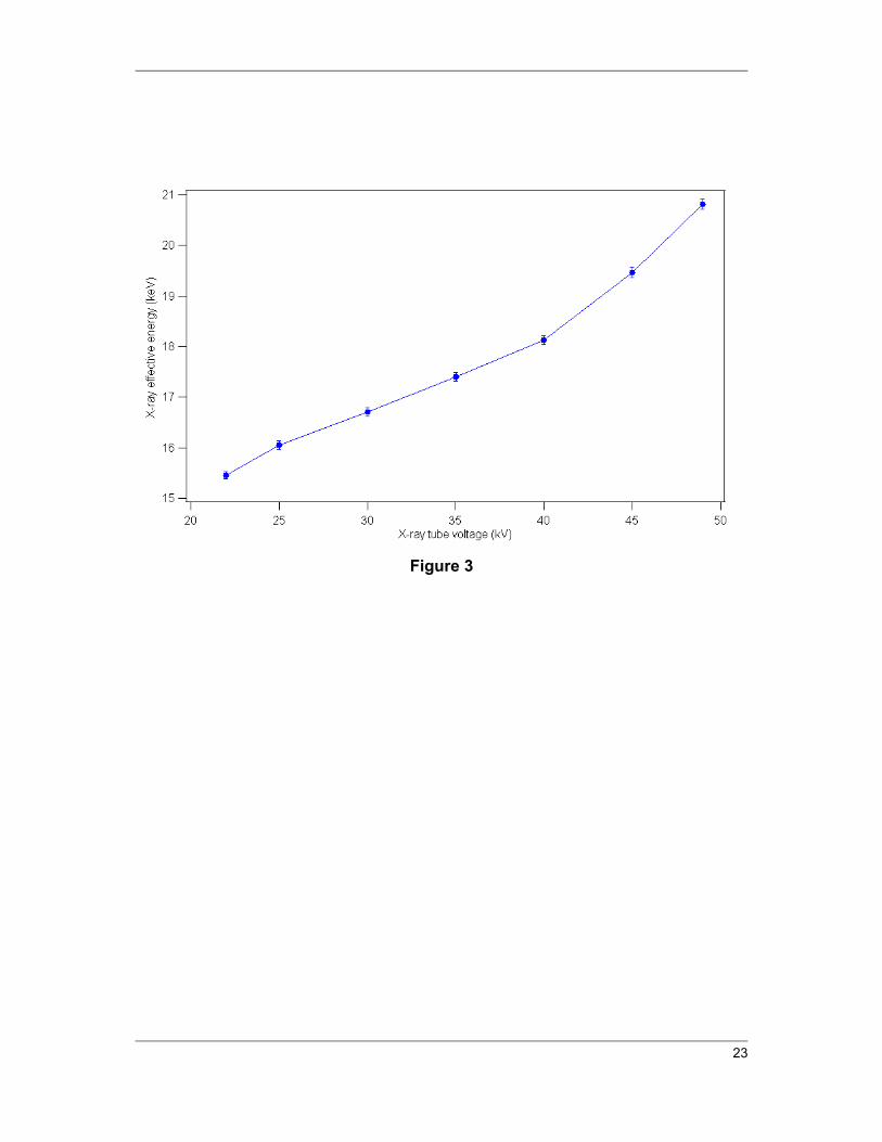
mammography X-ray effective energy operated at an X-ray tube voltage of 22–49 kV (Fig. 3). These
effective energies were determined using half-value layer (HVL) experiments (Suk et al., 2012) on the
mammography unit. With kilovoltage X-rays, determination of the HVL of the X-ray beam can be
used to characterize the effective energy by converting the measured HVL to the linear attenuation
coefficient. The effective energy of a polyenergetic beam is equal to the energy of a monoenergetic
X-ray beam that is attenuated at the same rate as the polyenergetic beam which can be determined
from tabulated data (Berger et al., 2010).
As can be seen from both Figs. 1 and 2, µ increased with an increase of the filler loading within the
PLA matrix for both electrospun n-Bi2O3/PLA and m-Bi2O3/PLA nanofibre mats, except for the 38
wt% Bi2O3 loading where there is a sudden decrease in µ. However, the difference in µ between
electrospun n-Bi2O3/PLA and m- Bi2O3/PLA nanofibre mats becomes higher as the Bi2O3 loading
increased. These findings support the density and porosity results discussed previously, including the
38 wt% of Bi2O3/PLA nanofibre mats which showed low density and high porosity, thus leading to
decreased µ. Meanwhile, a comparison of thin films between m-Bi2O3/PLA and n-Bi2O3/PLA does
not totally support the results found from this study for the electrospun Bi2O3/PLA nanofibre mats.
From Fig. 4, as the X-ray effective energy increased to >17.4 keV (i.e. X-ray tube voltages > 35 kV),
for the same wt% of Bi2O3 filler within this thin film sample, µ for m- Bi2O3/PLA thin film and µ by

10
n- Bi2O3/PLA thin film become comparable. They only show significant differences in µ for lower X-
ray effective energy, <17.4 keV (i.e. X-ray tube voltage 22–35 kV), operated from the mammography
unit.
As in our previous study for the comparison of different sizes of WO3 particles–epoxy composites
(Noor Azman et al., 2013), we also obtain similar results for electrospun Bi2O3/ PLA nanofibre mats
which showed that the attenuation by electrospun n-Bi2O3/PLA nanofibre mats is higher than the
attenuation by electrospun m-Bi2O3/PLA nanofibre mats with the same filler loading in the low-
energy regime (22–35 kV operated from the mammography unit). However, by increasing the X-ray
tube voltage beyond 35 kV (i.e. X-ray effective energy > 17.4 keV), the attenuation by electrospun
n-Bi2O3/PLA nanofibre mats is still higher than the attenuation by electrospun m-Bi2O3/PLA
nanofibre mats. In contrast, in our previous work, the differences in the attenuation by micro-sized
WO3–epoxy composites and nano-sized WO3– epoxy composites become indistinguishable when the
X-ray tube voltage was increased beyond 35 kV (Noor Azman et al., 2013). Only Bi2O3/PLA thin film
has a good agreement with our previous results for X-ray tube voltages greater than 35 kV, which
shows the indistinguishability in attenuation between m-Bi2O3/PLA thin film and n-Bi2O3/PLA thin
film.
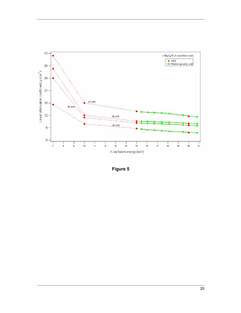
Fig. 5 presents the value of µ for electrospun n-Bi2O3/PLA nanofibre mats for all the X-ray beam
energies generated by XAS and the mammography unit. The results found from XAS were correlated
with those from the mammography unit since the mammography unit produced effective energies of
15–21 keV with the Mo and Rh anode/filter characteristic X-ray energies of 17.5–22.7 keV, while the
X-ray energy used with XAS was ~7–20 keV.
In essence, the total X-ray attenuation by the absorbing material is determined by three energy-
dissipative mechanisms, namely the photoelectric effect, Compton scattering and pair production. Pair
production was not considered in this study because this mechanism will only occur when the photon
energy is beyond 611 keV. In the photoelectric absorption process, a photon undergoes an interaction
with an absorber atom in which the photon completely disappears. In its place, an energetic
photoelectron is ejected from one of the bound shells of the atom. The photoelectric process is the
11
predominant mode of photon interaction at relatively low photon energies and high atomic number Z,
i.e. (Z/E)3. Meanwhile, Compton scattering takes place between the incident photon and one of the
outer-shell electrons of an atom in the absorbing material. The probability of Compton scattering is
almost independent of atomic number Z and X-ray energy E. It is most dominant as the photon energy
increases due to a concomitant decrease in the photoelectric effect.
In addition, the number of Bi particles per gram in both n-Bi2O3/PLA fibre mats and thin films is
higher than their micro-sized counterparts. Hence, the probability of X-rays with lower energies (i.e.
7–20 keV and 22–35 kV) interacting and being absorbed by n-Bi2O3 filler is higher when compared
with their micro-sized counterparts since the photons interact with the absorbing materials mainly by
the photoelectric effect.
As a consequence, electrospun n-Bi2O3/PLA nanofibre mats are superior to their micro-sized
counterparts in terms of X-ray attenuation for all the X-ray beam energies (i.e. 7–20 keV and 22–49
kV generated by XAS and mammography, respectively). In contrast, n-Bi2O3/PLA thin films are a
good X-ray shielding candidate only for the mammography unit at 22–35 kV when compared with m-
Bi2O3/PLA thin films. Both can be chosen as X-ray shielding materials for voltages greater than 35
kV. The observed similarity in the attenuation results for PLA thin films of n-Bi2O3 and m-Bi2O3 at
the X-ray tube voltage of the mammography unit of more than 35 kV may be attributed to: (a) the
decrease of the photoelectric effect, and (b) the domination of the Compton scattering effect when the
photon energy increases. The latter effect results in less interaction and absorption of the photons by
Bi particles of these thin films; thus the X-ray attenuation of the films is similar. In contrast,
electrospun n-Bi2O3/PLA nanofibre mats are superior to their micro-sized counterparts in terms of X-
ray attenuation at the same energy range. The observed large differences in X-ray attenuation of these
fibre mats may be explained by the difference in uniformity of dispersion between nano- and micro-
sized Bi particles within the PLA matrix where large agglomerations tend to occur in the latter, thus
affecting the final density of the composite.
Hence, the electrospun n-Bi2O3/PLA nanofibre mats of all filler loadings (24–38 wt%) are potential
candidates in X-ray shielding for all the incident X-ray energies studied either by XAS (7–20 keV) or

12
mammography (22–49 kV) when compared with their micro-sized counterparts. However, the latter
may still be a suitable candidate for X-ray attenuator of scattered radiation which requires lower
energy. These electrospun Bi2O3/PLA nanofibre mats can be used as a coating material for X-ray
shielding because PLA nanofibres provide many benefits such as higher tenacity, resistance to
degradation and mechanical properties (Farrington et al., 2005; Haroosh et al., 2012). Besides, since
PLA has a higher tenacity, these electrospun Bi2O3/PLA nanofibre mats can be fabricated as gloves to
be worn by radiation workers when holding radioactive materials or waste (non-clinical use), or used
as a liner on examination tables to help attenuate scattered X-rays coming out from patients during
medical diagnosis or therapy (using higher X-ray or γ-ray energies in the MeV range) performed by
specialist radiographers and radiologists (clinical use).
Meanwhile, n-Bi2O3/PLA thin films are good X-ray shielding candidates only for mammography at
25–35 kV, when compared with m-Bi2O3/PLA thin films. Both can be chosen as X-ray shielding
materials for X-ray tube voltages greater than 35 kV.
3.3. Microstructure analyses
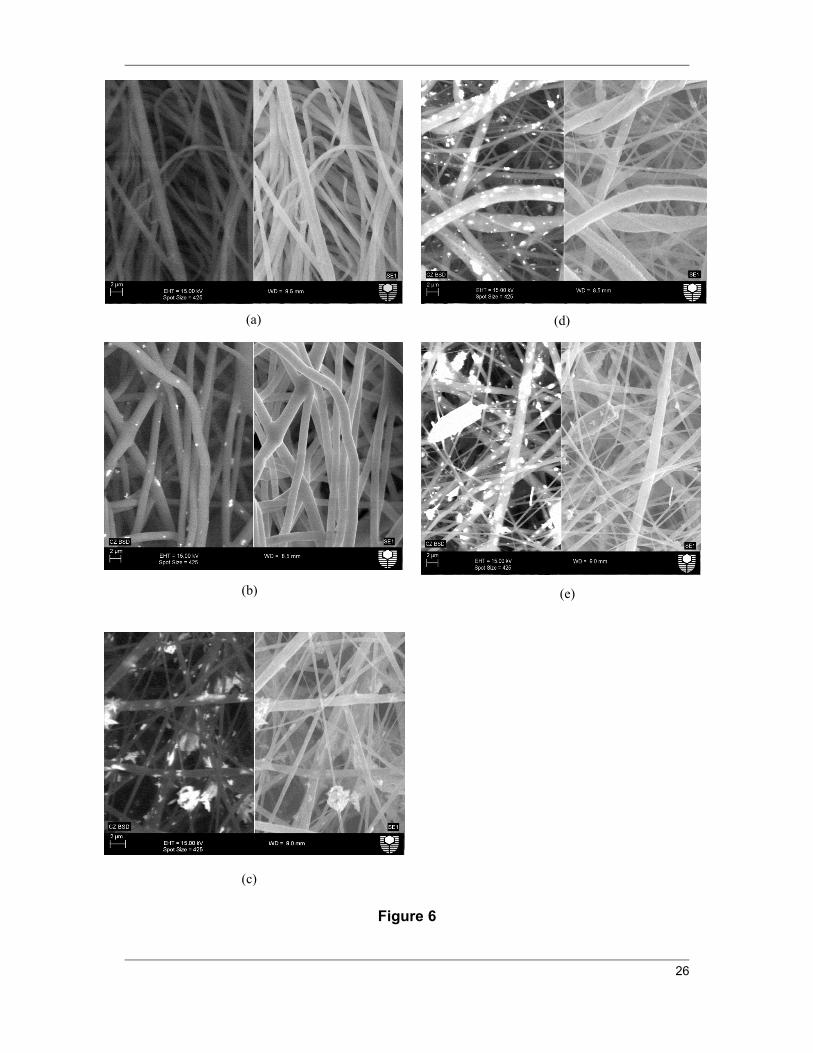
Microstructure analysis of the electrospun nanofibres was performed using both backscattered
electrons and secondary electrons to clearly show the difference between the PLA polymer and the
embedded Bi elements. Fig. 6(a) shows a SEM image of the control electrospun PLA nanofibres
without any Bi2O3 filler. The average diameter of these fibres was 854 ± 35 nm. The average diameter
of PLA nanofibres increased when 24–34 wt% Bi2O3 was added to the PLA solution. For instance,
Fig. 6(b) shows the homogeneous nanofibres of 28 wt% n-Bi2O3 filler with an average diameter of
971 ± 22 nm. Meanwhile, in Fig. 6(c) the average diameter of 28 wt% m-Bi2O3/PLA nanofibres is 911
± 41 nm with a large variation in fibre diameter and particle agglomerations can be observed.
This indicates that, by increasing the solution viscosity while both the conductivity and the surface
tension decreased with the increment of filler (Bi2O3) loadings within the PLA solution, the average
nanofibre diameter was increased. The significant increase in the viscosity of the solution with
increasing filler loadings was due to the increased molecular entanglement which enabled the charged

13
jet to withstand a larger stretching force (from the Coulombic repulsion) resulting in the coarsening of
the nanofibres.
In contrast, a further increase of Bi2O3 loading to 38 wt% caused a decrease in the average diameter to
496 ± 32 nm for n-Bi2O3/PLA nanofibres which have a maximum diameter of 2.06 ± 0.49 mm and a
minimum of 114 ± 2 nm (Fig. 6d). Meanwhile, the average diameter of m-Bi2O3/PLA nanofibres is
406 ± 71 nm with a maximum diameter of 1.13 ± 0.23 mm and a minimum of 111 ± 2 nm (Fig. 6e).
The unexpected decrease in the average fibre diameter may be attributed to the domination of
electrical conductivity when filler loading or viscosity of solution increases. As a result, this leads to
the production of fibres with non-uniform diameters, as well as formation of beads and particle
agglomerations.
Figs. 7(a)–7(c) illustrate the EDS results for the electrospun n-Bi2O3/PLA nanofibre mat with 34 wt%
filler loading which confirms the existence of the Bi element from the filler together with elements C
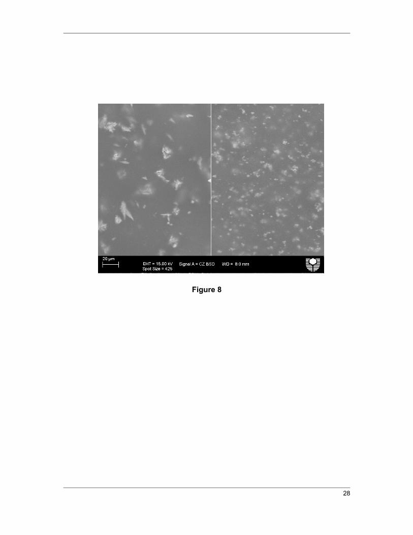
and O from the PLA matrix. SEM images of m-Bi2O3/PLA and n-Bi2O3/PLA thin films with 28 wt%
filler loading are shown in Fig. 8, indicating the presence of agglomerations within the PLA matrix.
4. Conclusions
Electrospun nanofibre mats of n-Bi2O3/PLA and m-Bi2O3/PLA with filler loadings of 24–38 wt%
have been successfully fabricated. From the analyses, the electrospun n-Bi2O3/PLA nanofibre mats of
all filler loadings were found to be superior in attenuating X-rays compared with their micro-sized
counterparts because n-Bi2O3 may provide more uniform materials since the particle size can affect
the microstructure and consequently the density and composition that will then modify the attenuation
coefficient of the composite. However, the electrospun Bi2O3/PLA nanofibre mats with 38 wt%
loading are not recommended for X-ray shielding because of higher porosity compared with the lower
filler loadings. The n-Bi2O3/PLA thin films are good X-ray shielding candidates only for the
mammography unit at 22–35 kV when compared with the m-Bi2O3/PLA thin films. The particle size
effect on X-ray attenuation diminished as the X-ray tube voltage.

14
Acknowledgements Part of this research was undertaken on the XAS beamline at the Australian
Synchrotron, Victoria, Australia. We thank our colleagues Dr. C. Ng and A/Prof. Z. Sun for assistance
with XAS data collection. Also, we would like to thank Carolyn Madeley of Breast Assessment
Centre, Royal Perth Hospital, Western Australia for giving us the opportunity to use the
mammography unit.
References
An, J.-S., Park, J.-S., Kim, J.-R. & Hong, K. S. (2006). Journal of the American Ceramic Society 89, 3658-3661.
Berger, M. J., Hubbell, J. H., Seltzer, S. M., Chang, J., Coursey, J. S., Sukumar, R., Zucker, D. S. & Olsen, K. (2010).
Botelho, M. Z., Künzel, R., Okuno, E., Levenhagen, R. S., Basegio, T. & Bergmann, C. P. (2011). Applied Radiation and Isotopes 69, 527-530.
Brettmann, B. K., Tsang, S., Forward, K. M., Rutledge, G. C., Myerson, A. S. & Trout, B. L. (2012). Langmuir 28, 9714-9721.
Buyuk, B., Tugrul, A. B., Akarsu, A. C. & Addemir, A. O. (2012). J. Nano- and Electronic Physics 4, 01010(01011)-01010(01014).
Chanthima, N., Kaekwkhao, J., Kedkaew, C., Chewpraditkul, W., Pokaipisit, A. & Limsuwan, P. (2011). Progress in Nuclear Sicence and Technology 1, 106-109.
Demir, M. M., Gulgun, M. A., Menceloglu, Y. Z., Erman, B., Abramchuk, S. S., Makhaeva, E. E., Khokhlov, A. R., Matveeva, V. G. & Sulman, M. G. (2004). Macromolecules 37, 1787-1792.
El Haber, F. & Froyer, G. (2008). Journal of the University of Chemical Technology and Metallurgy 43, 283-290.
Faccini, M., Vaquero, C. & Amantia, D. (2012). J. Nanomaterials 2012, 1-9. Farrington, D. W., Lunt, J., Davies, S. & Blackburn, R. S. (2005). Poly (lactic acid) fibers, pp. 191-
220. Cambridge, United Kingdom: Woodhead Publishing Series in Textiles. Granmayeh Rad, A., Abbasi, H. & Afzali, M. H. (2011). Physics Procedia 22, 203-208. Haiwen, X., Kai-Zhong, G., Yiming, S. & Song, X. (2006). Journal of Physics D: Applied Physics 39,
4746. Haroosh, H. J., Chaudhary, D. S. & Dong, Y. (2012). Journal of Applied Polymer Science 124, 3930-
3939. Hu, W., Huang, Z. M. & Liu, X. Y. (2010). Nanotechnology 21, 315104. Huang, S., Kang, X., Cheng, Z., Ma, P., Jia, Y. & Lin, J. (2012). J Colloid Interface Sci 387, 285-291. Huang, X. & El-Sayed, M. A. (2010). Journal of Advanced Research 1, 13-28. Künzel, R. & Okuno, E. (2012). Applied Radiation and Isotopes 70, 781-784. Lee, S. & Obendorf, S. K. (2007). Textile Research Journal 77, 696-702. M.G, L. (2008). Journal of Alloys and Compounds 449, 242-245. Molamma, P. P., Venugopal, J., Casey, K. C. & Ramakrishna, S. (2008). Nanotechnology 19, 455102. Noor Azman, N. Z., Siddiqui, S. A., Hart, R. & Low, I. M. (2013). Applied Radiation and Isotopes 71,
62-67. Patra, C. R., Bhattacharya, R., Mukhopadhyay, D. & Mukherjee, P. (2010). Advanced Drug Delivery
Reviews 62, 346-361. Popov, A. (2009). SPIE Newsroom 24, 1-2. Rajeswari, R., Jayarama Reddy, V., Subramanian, S., Shayanti, M., Radhakrishnan, S. & Seeram, R.
(2012). Nanotechnology 23, 385102. Robert, R. D. (2005).
15
Russo, G. & Lamberti, G. (2011). Journal of Applied Polymer Science 122, 3551-3556. Sahare, P. D., Ranju, R., Numan, S. & Lochab, S. P. (2007). Journal of Physics D: Applied Physics
40, 759. Shanshan, B., Jayaram, S. H. & Cherney, E. A. (2010). Electrical Insulation and Dielectric
Phenomena (CEIDP), 2010 Annual Report Conference on, pp. 1-4. Sill, T. J. & von Recum, H. A. (2008). Biomaterials 29, 1989-2006. Storrie, H. & Mooney, D. J. (2006). Advanced Drug Delivery Reviews 58, 500-514. Suk, C. C., Wei, L. J. & Harun, A. Z. (2012). Malays J Med Sci. 19, 22-28. Yiin-Kuen, F. & Li-Chih, L. (2013). Nanotechnology 24, 055301. Yu, D. G., Shen, X. X., Chris, B. W., Kenneth, W., Zhu, L. M. & Bligh, S. W. A. (2009).
Nanotechnology 20, 055104.

16
Table 1 Prepared electrospun nanofibre mats with different weight fractions of filler (Bi2O3) and
PLA.
Electrospun Bi2O3 PLA nanofibre mat by weight fraction (wt%)
Filler (Bi2O3) PLA
24 76
28 72
34 66
38 62

17
Table 2 Anode/filter combination operated by the mammography machine.
X-ray tube voltage (kV) Anode/filter combination
22
Mo/Moa
25
30
35
Mo/Rhb
40
45
Rh/Rhc
49
a Molybdenum anode/molybdenum filter.
b Molybdenum anode/rhodium filter.
c Rhodium anode/rhodium filter.

18
Table 3 Density of electrospun Bi2O3/PLA nanofibre mats and Bi2O3/PLA thin films.
Filler (Bi2O3) weight
fraction (wt%)
Density (cm3/g)
Theoretical
Electrospun nanofibre mat Thin films
nano micro nano micro
24 1.56 0.27 0.25 1.54 1.50
28 1.63 0.40 0.37 1.59 1.52
34 1.75 0.49 0.45 1.69 1.64
38 1.84 0.30 0.24 1.77 1.72

19
Table 4 Porosity of electrospun Bi2O3/PLA nanofibre mats.
Filler (Bi2O3)
weight fraction
(wt%)
Porosity (%)
Nano-Bi2O3/PLA nanofibre mat Micro-Bi2O3/PLA nanofibre mat
0 88.8 88.8
24 83.0 84.0
28 75.4 77.0
34 72.1 74.3
38 83.6 87.0

20
Figure 1 Linear attenuation coefficient as a function of synchrotron radiation energy operated by
XAS (7 – 20 keV) for all Bi2O3 loading (0 – 38 wt.%) of the electrospun n-Bi2O3/PLA and m-
Bi2O3/PLA nanofibre mats.
Figure 2 Linear attenuation coefficient as a function of effective energy operated by various X-ray
tube voltages of the mammography unit (22-49 kV) for all Bi2O3 loading (0 – 38 wt.%) of the
electrospun n-Bi2O3/PLA and m-Bi2O3/PLA nanofibre mats.
Figure 3 Effective energy as a function of the X-ray tube voltages operated by mammography unit
determined from half value layer measurements.
Figure 4 Linear attenuation coefficient as a function of the effective energy operated by various X-
ray tube voltages of the mammography unit (22-49 kV) for all Bi2O3 loading (0 – 38 wt.%) of the n-
Bi2O3/PLA and m-Bi2O3/PLA thin films.
Figure 5 Comparison of linear attenuation coefficient for the electrospun n-Bi2O3/PLA nanofibre
mats for all the X-ray beam energy generated by XAS unit and mammography unit.
Figure 6 SEM images using for each figure, the backscattered electron technique (left) and the
secondary electron technique (right) for (a) the control electrospun PLA nanofibres without any
particles (0 wt% of Bi2O3); (b) 28 wt% Bi2O3 of electrospun n- Bi2O3/PLA nanofibres; (c) 28 wt%
Bi2O3 of electrospun m-Bi2O3/PLA nanofibres; (d) 38 wt% Bi2O3 of electrospun n-Bi2O3/PLA
nanofibres; and (e) 38 wt% Bi2O3 of electrospun m-Bi2O3/PLA nanofibres.
Figure 7 (a) SEM image used for EDS analyses on 34 wt% Bi2O3 of the electrospun n-Bi2O3/PLA
nanofibres to prove that only Bi particles are detected other than C and O which is the composition of
PLA; EDS analyses for (b) point 1 and; (c) point 2 marked in (a).
Figure 8 SEM images of a thin film of 28 wt% Bi2O3 for m-Bi2O3/PLA on the left (clear
agglomerations can be seen) and n-Bi2O3/PLA on the right.

21
Figure 1

22
Figure 2
23
Figure 3

24
Figure 4
25
Figure 5
26
Figure 6
(a) (d)
(b) (e)
(c)

27
Figure 7
(a)
(b)
(c)
28
Figure 8