characteristics of flows around a rectangular cylinder...
TRANSCRIPT

1
BBAA VI International Colloquium on: Bluff Bodies Aerodynamics & Applications
Milano, Italy, July, 20-24 2008
CHARACTERISTICS OF FLOWS AROUND A RECTANGULAR CYLINDER OF WHICH VIBRATION IS SUPPRESSED BY
PULSATING JETS FROM THE LEADING EDGES
Takashi Nomura∗ and Katsunori Suzuki†
∗Departmento of Civil Engineering, College of Science and Technology, Nihon University 1-8-14, Kanda-Surugadai, Chiyoda-ku, Tokyo 101-8308, Japan
e-mail: [email protected],
† The Zenitaka Corporation 2-11, Nishi-Honmachi 2-chome, Nishi-ku, Osaka 550-0005, Japan
Keywords: Vibration control, Pulsating jet, Rectangular cylinder, Flow visualization.
Abstract. The present paper describes a series of specially arrange wind tunnel experiments in which vortex-induced vibration of a rectangular cylinder of B/D=2 is suppressed by apply-ing pulsating jet flows at the leading edges. The pulsation of the jet flows are generated by feedback from measured time histories of the cylinder displacement. Adequately chosen phase gap between the cylinder motion and the peak of pulsating jet leads to stationary cylinder within several cycles of cylinder vibration. In order to investigate the role of the pulsating jets, the flow velocity around the cylinder is measured by means of hot wire anemometer as well as visualized by green laser sheet. It is found that, when the cylinder vibration is suppressed, the separation shear layer of the suppressed cylinder does not reach clear vortex formation which is not strong enough to shake the cylinder.

Takashi Nomura and Katsunori Suzuki
2
1 INTRODUCTION There are a number of investigations to control flow-induced vibration of structures by
means of active operation to change behavior of separated flows. Among many approaches, some movable structural elements such as rotating circular cylinder or fluttering fin are de-vised near structural edges or corners [1-4]. On the contrary to these mechanical approaches, stimulation of the separation shear layers by sound is also effective to suppress the vortex-induced cylinder [5, 6].
The authors have conducted an experiment to stimulate the flow separation region of rec-tangular cylinder by pulsating jet which is ejected through thin slit along the leading edge [7]. Under adequate phase conditions, this method works successfully to suppress flow-induced vibration of rectangular cylinder of B/D=2.
In the present paper, in order to clarify the mechanism why such method can suppress the vibration, the flows around the cylinder are investigated by means of flow measurement and visualization. Consequently, it is found that the separation shear layers around the cylinder of suppressed vibration are smooth and weak in comparison with those of the fixed cylinder.
2 EXPERIMENTAL APPARATUS
2.1 Wind tunnel and the spring-suspended cylinder Fig. (1) schematically shows the experimental arrangement of the present investigation.
The duct of the wind tunnel has a rectangular cross section of 60cm height and 30cm width. The maximum wind velocity of the present wind tunnel is 10 m/s. A rectangular cylinder of which width/height ratio B/D=2 is suspended by four pairs of vertical coil springs. The mo-tion of the cylinder is measured by two laser linear gauges; one measures the vertical dis-placement of the leading edge of the cylinder while the other does that of the trailing edge. Two computer-controlled, AC servomotor driven wind blowers [8] take a role to inject air-streams into the rectangular cylinder through two tubes. Fig. (2) shows the details of the rec-tangular cylinder. The dimensions of the cylinder are 12cm width, 6cm height and 27cm span length in the axial direction. The mass of the cylinder is 180g and the natural frequency of the vertical translational vibration is 2.89 Hz when no wind is blowing.
Figure 1: The experimental apparatus. Figure 2: The rectangular cylinder specimen.

Takashi Nomura and Katsunori Suzuki
3
2.2 Jet flows to stimulate the leading edges of the cylinder As shown in Fig. (2), a thin straight slit of 0.4cm wide gap is opened along the leading end
of the top surface of the rectangular cylinder and another slit is opened along the leading end of the bottom surface. On one side wall of the cylinder, two tubes from the AC servomotor wind blowers are connected to two vertically aligned circular holes individually. The air stream generated by the AC servomotor wind blower is injected through the circular hole into a narrow duct inside of the cylinder. Traveling through this inside duct, the air stream is forced to change the direction and vertically spout as thin film of jet through the thin slit. As shown in Fig. (2), the internal cross section of the duct is shrinking stepwise. This internal configuration of the duct is determined after attempting several alternative configurations in order to make the jet profile as flat as possible and as strong as possible. Fig. (3) shows the velocity profile of the jet through the slit when the AC servomotor wind blower is driven steadily at the control voltage 8.95V (the maximum control voltage is 10V). The profile is not perfectly flat but the total flow rate is biggest among the attempted internal duct configura-tions. Fig. (4) shows the measured velocity of the jet at the slit point, of which distance from the intake end is 20cm. Also in Fig. (4) plotted are the velocities of the air stream generated by the AC servomotor wind blower without the tube. These velocities increase linearly by changing the voltage of the electric current which controls the rotation of the AC servomotor.
2.3 Target vibration to be suppressed The present rectangular cylinder reveals vertical translational vibration when the approach-
ing wind velocity exceeds 2.0m/s. Fig. (5) shows the vibration amplitudes of the rectangular cylinder at different velocities of the approaching wind. As the wind velocity increases, the frequency of the vibration increases from 2.5Hz to 2.8Hz. No rotational motion is observed.
Figure 3: Profile of jet from the slit at the con-trol voltage 8.95V.
Figure 4: The relation between the blower’s veloc-ity and the jet velocity at the slit point 20cm far from the intake hole.

Takashi Nomura and Katsunori Suzuki
4
2.4 Pulsating jet flows Applying sinusoidal time histories of control voltage to the AC servomotor wind blowers,
pulsating jets are generated through the thin slits. Fig. (6) shows an example of the measured pulsating jets. The time history of the input voltage of this particular case has the central volt-age 6.00V,the half amplitude1.57V and the period 0.38s. This measuring point is the same point as the measuring point of Fig. (4). It can be observed the velocity history of jet is pulsat-ing. Based on this measurement, it is confirmed that there is a time lag of 0.32s between the control voltage and the generated pulsating jet. This quantity is quite important to design feedback algorithms to suppress the vortex-induced vibration. In addition, it has been found that the present experimental apparatus cannot generate pulsating jets of which frequency is higher than 3.0Hz. However, the available frequency range sufficiently covers the frequencies of the target vortex-induced vibration.
3 STIMULATION BY THE STEADY JET Steady jet streams through the two thin slits have been found also effective to suppress the
vortex-induced vibration. Fig. (7) shows time histories of the cylinder displacement; the upper history is the case without jet, and the lower history is the case with steady jet flow are gener-ated through both the upper and lower slits. In this particular case, the velocity of the ap-proaching wind is 3.0m/s and the amplitude of the vibration is 12mm before generating the steady jet. The velocity of the jet is estimated 3.0m/s since the control voltage applied to the AC servomotor is 9.9V. As shown in Fig. (7), after generating the steady jet, the vibration amplitude gradually decreases. It is inferred that the steady jets along the upper and the lower leading edges become a kind of air curtain and disorganize separation shear layers.
Figure 5: The target cylinder vibration.
0
10
20
30
40
50
60
0 1 2 3 4 5
Double amplitude of model ( mm )
Wind Velocity ( m/s )
0
0.2
0.4
0.6
0.8
1.0Non-dimension amplitude
2A/D
5 10 15 20 25 30Reduced Velocity V/fD
0
Figure 6: Measured pulsating jet and the time lag from the control voltage.

Takashi Nomura and Katsunori Suzuki
5
Fig. (8) summarizes the effects of the steady jets for suppression of the cylinder vibra-
tion. The two lines indicate the ratios of reduced amplitude when the approaching wind ve-locities are 2.5m/s and 3.0m/s. The cases of 3.0m/s (the solid line) indicate that stronger steady jet is more effective to suppress the cylinder vibration. On the contrary, the cases of 2.5m/s (the dashed line) indicate that the strength of the steady jet stream is not so essential to suppress the cylinder vibration. For both cases of the approaching wind velocity, the applied voltage of 7.0V has no effect for the suppression.
These results show that jet stream to stimulate the leading edges has some function to change the behavior of the separation shear layers. Probably, formation of vortices in the wake region is disturbed.
4 STIMULATION BY THE PULSATING JET
4.1 Control voltage history to generate pulsating jets In case of pulsating jets, the time histories of control voltage are designed to feedback si-
multaneously measured vertical displacement of the cylinder. The applied time history of the control voltage ( )tV is defined in terms of the following function:
( ) ( ) bTtyatV ++−= θτ (1)
where ( )ty is the cylinder displacement history measured by the laser linear gauge, ( )s32.0=τ is the time lag between the timings of control voltage and generation of the jet
through the slit. The constants a and b are parameters to define the amplitude and the central value of the control voltage histories. T is the measured period of the vortex-induced vibration and θ is a coefficient to adjust the phase of the control voltage. Fig. (9) schematically shows the temporal relation of the cylinder displacement ( )ty , the control voltage ( )tV when 0=θ and generated pulsating jets of four phase delays of 4
32
14
1 ,,,0=θ .
Figure 7: Effect of steady jet. Time histories of the cylinder vibration.
-30-25-20-15-10-505
10
-10-5051015202530
0 5 10 15
Dis
plac
emen
t w
ithou
t jet
(mm
)
Displacem
entw
ith steady jet (mm
)
Time (s)
Figure 8: Summary of the suppressed amplitude ratios by steady jets.

Takashi Nomura and Katsunori Suzuki
6
In the present experiment, the central value of the control voltage is 6.95V (the correspond-
ing jet velocity is 1.49m/s) and the initial amplitude is 2.95V (the corresponding velocity am-plitude is 0.77m/s). As indicated in Eq. (1), the amplitude of the control voltage is proportional to that of the cylinder displacement ( )ty . Four cases of the phase
43
21
41 ,,,0=θ are conducted. In every case, the jet at the upper slit and the jet at the lower
slit keep opposite phase. The velocities of the approaching wind are 2.5m/s, 3.0m/s and 3.5m/s.
Fig. (10) shows the measured displacement history and the control voltage history in the
case that the approaching wind velocity is 3.0m/s and 0=θ . As the vibration is getting sup-pressed, the amplitude of the control voltage is also decreasing. As shown in Fig. (10), even after the cylinder vibration is suppressed, a jet of steady velocity 1.49m/s continues. However, as shown in Fig. (8), even if the steady jet of 1.49m/s (the corresponding control voltage is 6.95V) is applied from the beginning, such a large reduction of vibration as indicated in Fig.
Figure 10: An example of the actual control voltage history which is feed backed from the measured displacement history (the approaching velocity=3.0m/s, θ=0).
Figure 9: Phase relations between the cylinder displacement and the generated pulsating jets.
0 0.19 0.38 0.57 0.76 0.95 1.14
Cylinderdisplacement
y(t)
Jet velocity
Controlvoltage
V(t)
delay of 0.32s
Time (s)
T/4
θ=0 1/4 1/2 3/4
Takashi Nomura and Katsunori Suzuki
7
(10) is not achieved. In addition, the displacement histories of the leading edge and the trail-ing edge completely coincide to each other. It indicates that no rotational motion occurs even if the two jets through the upper and the lower slits always have the opposite phase.
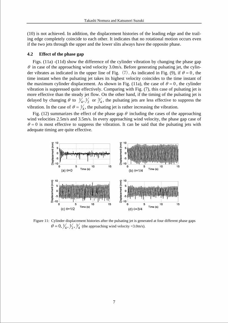
4.2 Effect of the phase gap Figs. (11a) -(11d) show the difference of the cylinder vibration by changing the phase gap
θ in case of the approaching wind velocity 3.0m/s. Before generating pulsating jet, the cylin-der vibrates as indicated in the upper line of Fig. (7). As indicated in Fig. (9), if 0=θ , the time instant when the pulsating jet takes its highest velocity coincides to the time instant of the maximum cylinder displacement. As shown in Fig. (11a), the case of 0=θ , the cylinder vibration is suppressed quite effectively. Comparing with Fig. (7), this case of pulsating jet is more effective than the steady jet flow. On the other hand, if the timing of the pulsating jet is delayed by changing θ to 2
14
1 , or 43 , the pulsating jets are less effective to suppress the
vibration. In the case of 41=θ , the pulsating jet is rather increasing the vibration.
Fig. (12) summarizes the effect of the phase gap θ including the cases of the approaching wind velocities 2.5m/s and 3.5m/s. In every approaching wind velocity, the phase gap case of
0=θ is most effective to suppress the vibration. It can be said that the pulsating jets with adequate timing are quite effective.
Figure 11: Cylinder displacement histories after the pulsating jet is generated at four different phase gaps
43
21
41 ,,,0=θ (the approaching wind velocity =3.0m/s).

Takashi Nomura and Katsunori Suzuki
8
5 MEASUREMENT AND VISUALIZATION OF FLOWS
5.1 Measurement by hot wire anemometer of flows around the cylinder As described above, if the separation shear layer just after the leading edge is stimulated by
pulsating jet, under adequate phase conditions, the vortex-induced vibration can be suppressed. In order to investigate the mechanism of this effect, fluid velocity of the separation shear layer and the wake are measured by hot wire anemometer. Fig. (13) shows the location of the measuring points around the cylinder. These points are aligned on the vertical plane at the center span of the cylinder. The approaching wind velocity is 3.0 m/s. The three measured cases are: the fixed cylinder; the vibrating cylinder without pulsating jet stimulation; and the suppressed cylinder by the pulsating jet of 0=θ . In case of the vibrating cylinder, the veloc-ity at the point No.8, No.9 and No.10 could not be measured since these points are too close to the vibrating cylinder.
Figure 12: Summary of the amplitude ratios.
0
0.2
0.4
0.6
0.8
1
1.2
1.4
-0.25 0 0.25 0.5 0.75 1
2.5m/s3.0m/s3.5m/s
Ampl
itude
ratio
s
Phase gap θ
Figure 13: Location of the points to measure the velocity by hot wire anemometer.

Takashi Nomura and Katsunori Suzuki
9
Fig. (14) and Fig. (15) are the contours of time-averaged stream velocity and the turbulent
intensity. As indicated in Fig. (14), the length of the wake region of the vibrating cylinder is shortest while that of the suppressed cylinder is longer than the others. According to Fig. (15), the flow field around the vibrating cylinder exhibits most strong fluctuation and the location of the maximum fluctuation is closest to the cylinder. The location of the maximum fluctua-tion of the fixed cylinder is relatively far from the cylinder. On the contrary to these two flow fields, the flow field around the suppressed cylinder looks quite smooth and one it is difficult to indicate most strongly fluctuating area. Although the cylinder is not moving in the cases of the fixed cylinder and the suppressed cylinder, the characteristics of the flow fields around these cylinders are quite different.
Figure 14: Distributions of the time-averaged stream velocities (from top: fixed cylinder, vibrating cylinder, cylinder suppressed by jet).
Figure 15: Distributions of the turbulent intensity (from top: fixed cyliner, vibrating cylinder, cylin-der suppressed by jet).
Takashi Nomura and Katsunori Suzuki
10
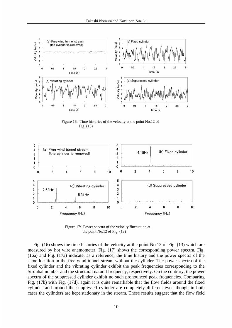
Fig. (16) shows the time histories of the velocity at the point No.12 of Fig. (13) which are
measured by hot wire anemometer. Fig. (17) shows the corresponding power spectra. Fig. (16a) and Fig. (17a) indicate, as a reference, the time history and the power spectra of the same location in the free wind tunnel stream without the cylinder. The power spectra of the fixed cylinder and the vibrating cylinder exhibit the peak frequencies corresponding to the Strouhal number and the structural natural frequency, respectively. On the contrary, the power spectra of the suppressed cylinder exhibit no such pronounced peak frequencies. Comparing Fig. (17b) with Fig. (17d), again it is quite remarkable that the flow fields around the fixed cylinder and around the suppressed cylinder are completely different even though in both cases the cylinders are kept stationary in the stream. These results suggest that the flow field
Figure 17: Power spectra of the velocity fluctuation at the point No.12 of Fig. (13)
Figure 16: Time histories of the velocity at the point No.12 of Fig. (13)

Takashi Nomura and Katsunori Suzuki
11
around the suppressed cylinder do not have vortex shedding strong enough to vibrate the cyl-inder.
5.2 Visualization of the flows Flow visualization by using dry ice mist and green laser sheet are also conducted. Fig.(18)
shows the visualized shear layer around the fixed cylinder and Fig. (19) shows that of the suppressed cylinder. Although vortex formation in the wake can be observed in Fig. (18), it cannot be clearly observed in Fig. (19). This unusual feature of flow is obtained as a result of stimulating the separation region by the pulsating jet, and apparently ineffective to exert shak-ing force for vortex-induced vibration.
6 CONCLUSIONS The present experimental study reveals that pulsating jet flows at the leading edges of a
rectangular cylinder of B/D=2 are effective to suppress the vortex-induced vibration. The first important finding here is that the suppression is effective when the phase of the jet flow is adequately adjusted. The most effective phase is that the jet takes its maximum velocity at the instant when the vibrating cylinder reaches its maximum displacement. At this timing of the maximum displacement, the small eddies begin to develop at the leading edge and it is in-ferred that the pulsating jet is preventing their natural development. At other phases, the vor-tex-induced vibration is not considerably suppressed or even magnified. The most effective pulsating jet is more effective than stimulation by steady jet flows.
The flow measurement and visualization suggest that the separation shear layer of the sup-pressed cylinder does not reach clear vortex formation which is not strong enough to shake the cylinder. This strange situation has been obtained by stimulating the separation region by the pulsating jet and sustained by keeping the jet steadily.
REFERENCES
[1] Y. Kubo. Prospects for the Suppression of Aerodynamic Vibrations of a Long-Span Bridge Using Boundary-Layer Control, Journal of Vibration and Control, 10(9), 1359-1373, 2004.
Figure 19: Visualized shear layer around the cylinder suppressed by jet.
Figure 18: Visualized shear layer around the fixed cylinder.

Takashi Nomura and Katsunori Suzuki
12
[2] S. Suganuma, A. Yoshida, Y. Tamura and V.J. Modi. Wake buffeting control by a prism with rotors or a vibrating plate, Proceedings of the Second World Conference on Structural Control, 1833-1840. 1998,
[3] K. Wilde and Y. Fujino. Aerodynamic Control of Bridge Deck Flutter by Active Sur-faces”, Journal of Engineering Mechanics, American Society of Civil Engineers, 124(7), 718-727, 1998.
[4] K. Wilde, Y. .Fujino and T. Kawakami “Analytical and experimental study on passive aerodynamic control of flutter of bridge deck section”, Journal of Wind Engineering and Industrial Aerodynamics, 80(1-2), 105-119, 1999.
[5] S. Hiejima, T. Nomura, K. Kimura, and Y. Fujino. Numerical study on the suppression of the vortex-induced vibration of a circular cylinder by acoustic excitation. Journal of Wind Engineering and Industrial Aerodynamics, 67 & 68, 325–335, 1997.
[6] S. Hiejima and T. Nomura. Numerical study of the effect of periodic jet excitation on cylinder aerodynamic instability, Wind & Structures, 5 (2-4), 141-150, 2002.
[7] T. Nomura, T. Okada, K. Takagi and K. Suzuki. Vibration control of a rectangular cyl-inder of B/D=2 by pulsating jets from the leading edges, Proceedings of APCWE VI, 220, Seoul, Korea, 2005.
[8] T. Nomura, Y. Suzuki, M. Uemura and N. Kobayashi. Aerodynamic forces on a square cylinder in oscillating flow with mean velocity, Proceedings of APCWE V, 481-484, Kyoto, Japan, 2001.